WO2019058647A1 - All-weather motor - Google Patents
All-weather motor Download PDFInfo
- Publication number
- WO2019058647A1 WO2019058647A1 PCT/JP2018/020968 JP2018020968W WO2019058647A1 WO 2019058647 A1 WO2019058647 A1 WO 2019058647A1 JP 2018020968 W JP2018020968 W JP 2018020968W WO 2019058647 A1 WO2019058647 A1 WO 2019058647A1
- Authority
- WO
- WIPO (PCT)
- Prior art keywords
- motor
- case body
- opening
- axial direction
- filter material
- Prior art date
Links
Images

Classifications
-
- H—ELECTRICITY
- H02—GENERATION; CONVERSION OR DISTRIBUTION OF ELECTRIC POWER
- H02K—DYNAMO-ELECTRIC MACHINES
- H02K1/00—Details of the magnetic circuit
- H02K1/06—Details of the magnetic circuit characterised by the shape, form or construction
- H02K1/22—Rotating parts of the magnetic circuit
- H02K1/27—Rotor cores with permanent magnets
- H02K1/2786—Outer rotors
- H02K1/2787—Outer rotors the magnetisation axis of the magnets being perpendicular to the rotor axis
- H02K1/2789—Outer rotors the magnetisation axis of the magnets being perpendicular to the rotor axis the rotor consisting of two or more circumferentially positioned magnets
- H02K1/2791—Surface mounted magnets; Inset magnets
-
- H—ELECTRICITY
- H02—GENERATION; CONVERSION OR DISTRIBUTION OF ELECTRIC POWER
- H02K—DYNAMO-ELECTRIC MACHINES
- H02K5/00—Casings; Enclosures; Supports
- H02K5/04—Casings or enclosures characterised by the shape, form or construction thereof
- H02K5/10—Casings or enclosures characterised by the shape, form or construction thereof with arrangements for protection from ingress, e.g. water or fingers
-
- H—ELECTRICITY
- H02—GENERATION; CONVERSION OR DISTRIBUTION OF ELECTRIC POWER
- H02K—DYNAMO-ELECTRIC MACHINES
- H02K5/00—Casings; Enclosures; Supports
- H02K5/04—Casings or enclosures characterised by the shape, form or construction thereof
- H02K5/20—Casings or enclosures characterised by the shape, form or construction thereof with channels or ducts for flow of cooling medium
- H02K5/207—Casings or enclosures characterised by the shape, form or construction thereof with channels or ducts for flow of cooling medium with openings in the casing specially adapted for ambient air
-
- H—ELECTRICITY
- H02—GENERATION; CONVERSION OR DISTRIBUTION OF ELECTRIC POWER
- H02K—DYNAMO-ELECTRIC MACHINES
- H02K9/00—Arrangements for cooling or ventilating
- H02K9/02—Arrangements for cooling or ventilating by ambient air flowing through the machine
- H02K9/04—Arrangements for cooling or ventilating by ambient air flowing through the machine having means for generating a flow of cooling medium
- H02K9/06—Arrangements for cooling or ventilating by ambient air flowing through the machine having means for generating a flow of cooling medium with fans or impellers driven by the machine shaft
-
- H—ELECTRICITY
- H02—GENERATION; CONVERSION OR DISTRIBUTION OF ELECTRIC POWER
- H02K—DYNAMO-ELECTRIC MACHINES
- H02K7/00—Arrangements for handling mechanical energy structurally associated with dynamo-electric machines, e.g. structural association with mechanical driving motors or auxiliary dynamo-electric machines
- H02K7/14—Structural association with mechanical loads, e.g. with hand-held machine tools or fans
Definitions
- the present disclosure relates to an all-weather motor used exposed outdoors as a driving source of, for example, a remotely operated unmanned aerial vehicle (commonly called a drone).
- a remotely operated unmanned aerial vehicle commonly called a drone.
- Patent Document 2 Japanese Patent Application Laid-Open No. 2009-290981.
- a motor used as a drive source of a remotely operated unmanned aerial vehicle is often used mainly at high power outdoors.
- the motor is continuously used at a high output, it is necessary to make the opening of the motor case large in order to generate a large amount of heat inside the motor and to increase the heat dissipation.
- this structure can not prevent the entry of foreign matter such as dust and sand from the outside and the entry of water, which may cause a motor lock.
- adopting a fully closed type motor without an opening in the motor case prevents foreign matter and water from entering the motor, but it can not release the heat generated by the motor, and a high output can not be obtained, so flying Performance may be degraded.
- an all-weather motor having a dustproof / drip-proof function that prevents deterioration of motor performance due to heat generation of the motor while preventing foreign matter and water from entering the motor.
- An object of the present invention is to provide a highly durable all-weather motor capable of maintaining the performance of a motor by improving the drip-proof performance.
- a mounting base a bearing housing integrally assembled to the mounting base, a stator having a stator core integrally assembled to the bearing housing, and a rotor magnet supported to be opposed to the stator core And a rotor rotatably supported by the bearing housing via the bearing, the rotor covers the outer peripheral side of the stator and both axial end sides of the bearing housing, and also has one axial end.
- the rotary case body having an intake opening on the side and the exhaust opening on the other end side in the axial direction, and a fin provided on the other end side in the axial direction in the rotary case body, The intake opening and the exhaust opening are each covered with a filter material having a predetermined opening diameter.
- the stator and the rotor that constitute the motor are covered at the axial direction both ends and the outer peripheral surface by the rotating case body, foreign matter and water do not easily enter the motor, and for the intake side opening and exhaust Since the opening is covered with the filter material, the dustproof and dripproof effect is high.
- the rotating case integrated with the rotor rotates, and the fins provided in the rotating case rotate, so that the air is taken in from the intake opening at one axial end side of the rotating case. Hot air generated in the motor can be fed radially outward by fins on the other axial end side and exhausted from the exhaust opening.
- it is possible to provide an all-weather type motor capable of preventing the decrease in motor performance by improving the heat dissipation of the motor and enhancing the dustproof and drip-proof performance to maintain the motor performance.
- the air is taken in in the axial direction through the filter material from the intake side opening portion provided on the one end side in the axial direction of the rotation case body, and the diameter is provided by the fins provided on the inner surface of the other end in the axial direction of the rotation case body It is preferable that the air is discharged toward the outside in the direction and exhausted from the exhaust opening through the filter material.
- the filter material can prevent the entry of foreign matter and water while improving the heat dissipation and maintaining the motor performance.
- the drip-proof performance can be enhanced by the exhaust from the exhaust opening together with the presence of the filter material.
- the filter material has an opening diameter smaller than the gap between the stator pole teeth and the rotor magnet.
- the filter material covering the intake opening be replaceable.
- the filter material covering the air intake opening is easily contaminated because dust and foreign matter are removed when the outside air is taken in, and the filter function is easily deteriorated, which facilitates maintenance work.
- the air is taken in through the intake opening provided axially downward of the rotating case body and exhausted through the exhaust opening provided radially outward on the axial direction.
- air is taken in from the intake opening provided axially downward, and exhausted from the exhaust opening provided radially outward on the axial direction from the intake opening.
- the position at which the intake opening is provided is preferably a curved lower end surface in the case of a bottomed cylindrical body in the case of a bottomed cylindrical body, for example, in consideration of drip-proofness, and the end face does not exist in the rotational case body. In the case, it is desirable to be provided on the axially lower surface.
- an all-weather motor 2 used as a drive source for an unmanned aerial vehicle (so-called drone) will be illustrated and described.
- An unmanned aerial vehicle (not shown) transmits an operation signal by a transmitter by remote control, and flies a propeller driven by a plurality of motor supported by a body frame at high speed to fly.
- a flight controller is provided in the airframe frame, and the motor drive is controlled by the transmission signal received through the receiver.
- a DC brushless motor is used as the all-weather motor 2.
- an outer rotor type motor expected to have a high output is preferably used.
- a propeller 3 is integrally attached to the rotor of the all-weather motor 2 as described later. More specifically, a pedestal plate 5 is fixed by a plurality of screws 6 at the center of the upper end surface of the rotating case 4 constituting the rotor. The tip end of the screw 6 is screwed to the rotating case body 4 and assembled integrally (see FIG. 2).
- a shaft 5 a is provided on the upper surface of the base plate 5 in a protruding manner. The shaft 5 a is inserted into the shaft hole 3 a (see FIG.
- a stop plate 7 is fixed on the propeller 3 in a superimposed manner.
- the retaining plate 7 has the shaft portion 5a inserted into the shaft hole 7a (see FIG. 2), superimposed on the propeller 3, and integrally fixed by a screw 8.
- the mounting base 10 is used, for example, when fixing a DC brushless motor to an airframe frame (not shown) of an unmanned aerial vehicle.
- a screw hole 10a for screwing and fixing to a mounting surface such as an airframe frame is bored.
- the mounting base 10 is provided with a through hole 10 b at the center to reduce the weight.
- One end portion 11 a of the cylindrical bearing housing 11 is integrally fixed by a screw 11 b in a state of being superimposed on the mounting base 10 and standing upright.
- the stator core 12 is integrally assembled to the bearing housing 11 by press-fitting, bonding, screwing, or a combination thereof.
- the stator core 12 may be a laminated core obtained by laminating and pressing electromagnetic steel sheets, an integrated core formed by electric discharge machining or laser cutting of a metal plate, or a core of another form such as a sintered metal core obtained by firing metal powder.
- the stator core 12 has a plurality of pole teeth 12a protruding radially from an annular core back portion.
- a coil 13 is wound around each pole tooth 12a through insulation coating or an insulator.
- the rotating case body 4 constituting the rotor 14 is rotatably supported on both ends in the longitudinal direction of the bearing housing 11 via a first bearing 15 and a second bearing 16.
- the first bearing 15 and the second bearing 16 are fixed to the outer periphery of the bearing housing 11 by, for example, press fitting, bonding, gap fitting, or the like.
- the rotating case body 4 is a stator core having a first case body 4a covering the outer peripheral side and one axial end of the bearing housing 11, and a second case body 4b covering the outer peripheral side of the bearing housing 11 and the other axial end
- the annular back yoke 4c covering the outer peripheral side of 12 is sandwiched and integrally assembled.
- the first case body 4a and the back yoke 4c are adhesively fixed, and the second case body 4b and the back yoke 4c are screwed and fixed by a fixing screw 19 (see FIG. 1).
- the back yoke 4c is made of a magnetic material (iron, magnetic material such as SUS) to form a magnetic path.
- An annular rotor magnet 4d in which N and S poles are alternately magnetized in the circumferential direction, is supported on the inner peripheral surface of the annular back yoke 4c.
- the rotor magnet 4 d is disposed to face the tips of the pole teeth 12 a of the stator core 12.
- intake openings 4e are provided at a plurality of places.
- the stator core 12 and the coil 13 (the stator 9) are cooled by being axially sucked from the intake opening 4e.
- Fins 17 are integrally assembled to the axially inner end surface 4b1 of the second case body 4b by screws 17a.
- the fins 17 are assembled by screwing together the base plate 17b on the axially inner end surface 4b1.
- a plurality of vanes 17c extending in the radial direction are erected on the base plate 17b in the circumferential direction.
- an exhaust opening 4f is provided on a side surface facing the outer peripheral tip end of the wing plate 17c of the second case body 4b.
- the intake opening 4e and the exhaust opening 4f are covered with a breathable water-repellent filter material 18 (for example, a mesh sheet such as nylon 66) having a predetermined opening diameter (see FIG. 3).
- the filter material 18 is fixed to the inner peripheral surface of the first case body 4a and the second case body 4b by adhesion or the like.
- the opening diameter of the filter material 18 (for example, a rectangular hole having a side of 77 ⁇ m) is preferably smaller than the gap (for example, 160 ⁇ m) between the stator pole teeth 12a and the rotor magnet 4d.
- the filter material 18 covering the intake opening 4e may be fixed by adhesion or the like, but it is desirable that the filter material 18 be exchangeably provided, for example, through an attachment (not shown). As a result, the filter material 18 covering the intake side opening 4e is easily contaminated because dust and foreign matter are removed when the outside air is taken in, and the filter function is apt to be deteriorated, which facilitates maintenance work.
- the filter material 18 is not limited to the mesh sheet material and may be a porous sheet material such as a sponge. Further, the material may be either a resin material or a metal material.
- the filter material 18 Since the hot air is discharged radially outward by rotation of the fins 17 and exhausted from the exhaust opening 4f through the filter material 18, the filter material 18 improves the heat dissipation property and maintains the motor performance while the filter material 18 removes foreign matter and water It can also prevent intrusion.
- the air is taken in through the intake opening 4e provided axially downward with the presence of the filter material 18 and exhausted through the exhaust opening 4f provided radially outward on the axial direction therefrom, Water is less likely to enter the opening, and the drip-proof performance can be enhanced.
- both the stator 9 and the rotor 14 constituting the all-weather motor 2 are covered with the rotating case body 4 in the axial direction at both ends and the outer peripheral surface, foreign matter hardly penetrates into the motor 2. Since the opening 4 e and the exhaust opening 4 f are covered with the filter material 18, the dustproof and drip-proof effect is high. Further, when the all-weather motor 2 is started, the rotation case 4 integrated with the rotor 14 is rotated, and the fins 17 provided in the rotation case 4 are rotated. It is possible to take in air from the air intake opening 4e on the side and send out the hot air generated inside the motor radially outward by the fin 17 on the other axial end side and exhaust it from the air discharge opening 4f. As a result, it is possible to provide an all-weather type motor 2 capable of preventing the motor performance from being degraded by enhancing the heat dissipation of the motor and enhancing the dustproof and drip-proof performance to maintain the motor performance.
- the pedestal plate 5 is fixed in advance to the second case body 4b of the rotating case body 4 by a plurality of screws 6 (see FIG. 3). Insert the shaft 5a protruding from the base plate 5 into the shaft hole 3a of the propeller 3 to assemble the propeller 3 on the base plate 5, insert it into the shaft hole 7a and overlap the stop plate 7 on the propeller 3 It is integrally fixed by the screw 8. Further, the filter material 18 is adhered to cover the outer surface side of the intake opening 4e of the first case body 4a and the inner surface side of the exhaust opening 4f of the second case body 4b (see FIG. 4).
- a stator 9 is integrally assembled to a bearing housing 11 screwed to a mounting base 10. Further, the first bearing 15 and the second bearing 16 are respectively assembled to both end portions in the longitudinal direction of the bearing housing 11.
- the first case body 4 a is rotatably supported by the bearing housing 11 via the first bearing 15, and the second case body 4 b is rotatably supported by the bearing housing 11 via the second bearing 16. (See Figure 3).
- the fins 17 are integrally screwed to the axially inner end surface 4b1 of the second case body 4b by screws 17a.
- the back yoke 4c supporting the rotor magnet 4d is assembled by being fitted to the open end of the first case body 4a and the second case body 4b. Then, the first case body 4a and the back yoke 4c are adhesively fixed, and the fixing screw 19 is screwed into the overlapping portion of the second case body 4b and the back yoke 4c, whereby the first case body 4a and the second case The body 4b is assembled integrally via the back yoke 4c.
- the rotating case 4 integrated with the rotor 14 is rotated.
- the fins 17 in the rotating case 4 rotate, so that the hot air generated in the motor is axially sucked from the intake opening 4 e at one axial end of the rotating case 4 at the other axial end.
- the fins 17 can be fed radially outward to exhaust air from the exhaust opening 4f.
- FIG. 5 a modified example of the all-weather type motor 2 is shown in FIG. 5 and FIG.
- the same members as those in the embodiment shown in FIGS. 1 to 4 are denoted by the same reference numerals, and the description will be incorporated, and different configurations will be mainly described.
- the all-weather motor 2 described above is used as a drive source for an unmanned aerial vehicle, and the first case body 4a and the second case body 4b of the rotating case body 4 are arranged with their tops and bottoms facing each other. It is also possible to use the propeller 3 upside down.
- intake openings 4e are provided at a plurality of places.
- the stator core 12 and the coil 13 (the stator 9) are cooled by being axially sucked from the intake opening 4e.
- Fins 17 are integrally assembled to the axially inner end surface 4a2 of the first case body 4a by screws 17a.
- the fins 17 are assembled by screwing the base plate 17b on the axially inner end surface 4a2.
- a plurality of vanes 17c extending in the radial direction are erected on the base plate 17b in the circumferential direction.
- an exhaust opening 4f is provided on the side surface of the first case body 4a that faces the outer peripheral tip end of the wing plate 17c.
- the air taken in in the axial direction from the intake opening 4e is sent out in the circumferential direction and exhausted from the exhaust opening 4f.
- foreign matter such as dust can be prevented from being caught by the gap between the stator pole teeth 12a and the rotor magnet 4d to cause the motor lock, and the waterproof of the intake opening 4e and the exhaust opening 4f A drip-proof function can also be secured.
- the base plate 5 is fixed in advance to the second case body 4 b constituting the rotating case body 4 by a plurality of screws 6. Insert the shaft 5a protruding from the base plate 5 into the shaft hole 3a of the propeller 3 to assemble the propeller 3 on the base plate 5, insert it into the shaft hole 7a and overlap the stop plate 7 on the propeller 3 It is integrally fixed by the screw 8. Further, the filter material 18 is adhered to cover the outer surface side of the intake opening 4e of the second case body 4b and the inner surface side of the exhaust opening 4f of the first case body 4a.
- a stator 9 is integrally assembled to a bearing housing 11 screwed to a mounting base 10. Further, the first bearing 15 and the second bearing 16 are respectively assembled to both end portions in the longitudinal direction of the bearing housing 11.
- the first case body 4 a is rotatably supported by the bearing housing 11 via the first bearing 15, and the second case body 4 b is rotatably supported by the bearing housing 11 via the second bearing 16. .
- the fins 17 are integrally screwed to the axially inner end surface 4a2 of the first case body 4a with screws 17a and assembled. Further, the back yoke 4c supporting the rotor magnet 4d is assembled by being fitted to the open end of the first case body 4a and the second case body 4b. Then, the first case body 4a and the back yoke 4c are adhesively fixed, and the fixing screw 19 (see FIG. 1) is screwed into the overlapping portion of the second case body 4b and the back yoke 4c to form the first case body 4a.
- the second case body 4b is integrally assembled via the back yoke 4c.
- the rotating case 4 integrated with the rotor 14 When the all-weather motor 2 is activated as shown in FIG. 5, the rotating case 4 integrated with the rotor 14 is rotated. At this time, the fins 17 in the rotating case 4 rotate, so that the hot air generated in the motor 2 is axially sucked from the intake opening 4e at one axial end of the rotating case 4 and the other end in the axial direction It is possible to send out radially outward by the side fins 17 and exhaust air from the exhaust opening 4f. Accordingly, it is possible to provide an all-weather motor 2 capable of preventing motor performance deterioration by enhancing the heat dissipation of the motor and maintaining the motor performance by enhancing the dustproof and drip-proof performance to prevent the entry of foreign matter Can.
- the all-weather motor 2 shown in FIG. 2 and the all-weather motor 2 shown in FIG. 5 such that the mounting bases 10 face the upper and lower sides of the body frame of the unmanned aircraft.
- the propellers 3 all-weather type motor 2
- they are driven to rotate in forward and reverse directions, and the motor vibrations acting on the body frame cancel each other in opposite directions. Vibration can be reduced even by doubling. Also, even if the all-weather motor 2 shown in FIGS.
- each rotary case 4 is sucked from the intake opening 4e axially lower to be axially upper Since the air is exhausted from the side exhaust opening 4f, the motor performance can be maintained by enhancing the dustproof and drip-proof performance to prevent the entry of foreign matter and water.
- the all-weather motor 2 described above uses a DC brushless motor, it may be another motor such as a DC brush motor.
- the fins 17 screwed to the rotating case 4 may be formed integrally with the rotating case 4 (the first case 4 a or the second case 4 b).
- the rotary case body 4 is a cylindrical body with a bottom, as described above, the lower end face in the axial direction is preferable in view of drip-proof property, but no end face exists in the rotary case body 4 In the case of a curved surface, it is desirable to be provided on the axially lower surface.
- the filter material 18 may be made of various materials and in various forms such as resin porous materials and metal mesh materials as long as it can ensure water repellency, air permeability and dust resistance. Furthermore, in the embodiment described above, the all-weather motor 2 has been described as a drive source for an unmanned aerial vehicle, but the application is not limited to this, and the drive for other applications used outdoors It can also be applied as a source.
Landscapes
- Engineering & Computer Science (AREA)
- Power Engineering (AREA)
- Motor Or Generator Frames (AREA)
- Motor Or Generator Cooling System (AREA)
Abstract
The present invention addresses the problem of providing a highly durable all-weather motor capable of maintaining motor performance in such a way that the degradation of the motor performance is prevented by enhancing a heat dissipation property and the intrusion of foreign objects is prevented by enhancing dust-proof and drip-proof properties. The problem is solved as followed. A rotor (14) has: a rotating case body (4) covering the outer circumferential side of a stator core (12) and both end sides of a bearing housing (11) in the axial direction, having an intake opening portion (4e) on one end side in the axial direction, and having a discharge opening portion (4f) on the other end side in the axial direction, said intake opening portion (4e) taking in air in the axial direction, said discharge opening portion (4f) discharging air in the radial direction; and a fin (17) provided on the inner surface of the rotating case body (4) at the other end in the axial direction. The intake opening portion (4e) and the discharge opening portion (4f) are each covered with a water-shedding filter material (18) having a predetermined opening size.
Description
本開示は、例えば遠隔操縦される無人航空機(通称ドローン)等の駆動源として屋外で露出した状態で使用される全天候型モータに関する。
The present disclosure relates to an all-weather motor used exposed outdoors as a driving source of, for example, a remotely operated unmanned aerial vehicle (commonly called a drone).
一般にモータは、運転を開始するとコイルの発熱等によりハウジング内に熱が籠りやすくなり、モータの発熱が大きくなるとモータ性能が低下するため、モータ内部を冷却する必要がある。このため、モータハウジングの一端側に放熱ファンを設け、一端側に設けられた空気取り込み孔からを内部空間に空気流を取り込み、モータ内部の熱気をモータハウジングの他端側の排風口より排出するようにして放熱性を高めた開放型のモータが提案されている(特許文献1:特開2017-17983号公報参照)。
これとは対照的にポンプユニットにモータユニットが組み付けられる場合、モータカバー内にモータが収容されると共にモータベースに対してモータカバーが接合されて密閉された全閉型のモータも提案されている(特許文献2:特開2009-290981号公報参照)。 In general, when the motor is started, heat is likely to be dissipated in the housing due to heat generation of the coil and the like, and if the heat generation of the motor is large, the motor performance is degraded, so it is necessary to cool the inside of the motor. For this reason, a heat dissipation fan is provided at one end of the motor housing, and an air flow is taken into the internal space from the air intake hole provided at one end, and the hot air inside the motor is exhausted from the air outlet of the other end of the motor housing. Thus, an open motor with improved heat dissipation has been proposed (see Patent Document 1: JP-A-2017-17983).
In contrast to this, when the motor unit is assembled to the pump unit, a fully closed type motor is also proposed in which the motor is accommodated in the motor cover and the motor cover is joined to the motor base and sealed. (Patent Document 2: Japanese Patent Application Laid-Open No. 2009-290981).
例えば、遠隔操縦される無人航空機(通称ドローン)の駆動源として使用されるモータは、主に屋外で高出力で使用される場合が多い。モータを高出力で使用し続ける場合、モータ内部の発熱が大きく熱放散性を大きくするため、モータケースの開口部を大きくとる必要がある。しかしながら、この構造では外部からの塵埃や砂等の異物や水の侵入を防ぐことができずモータロックを引き起こすおそれがある。
これに対し、モータケースに開口部の無い全閉型のモータを採用すると、モータ内への異物や水の侵入は防げるが、モータの発熱を逃がすことができないため高出力が得られず、飛行性能が低下してしまうおそれがある。
このように、モータ発熱によるモータ性能の低下を防ぐ反面、モータ内に異物や水が侵入するのを防ぐ防塵防滴機能を備えた全天候型モータが必要とされている。 For example, a motor used as a drive source of a remotely operated unmanned aerial vehicle (commonly called drone) is often used mainly at high power outdoors. When the motor is continuously used at a high output, it is necessary to make the opening of the motor case large in order to generate a large amount of heat inside the motor and to increase the heat dissipation. However, this structure can not prevent the entry of foreign matter such as dust and sand from the outside and the entry of water, which may cause a motor lock.
On the other hand, adopting a fully closed type motor without an opening in the motor case prevents foreign matter and water from entering the motor, but it can not release the heat generated by the motor, and a high output can not be obtained, so flying Performance may be degraded.
Thus, there is a need for an all-weather motor having a dustproof / drip-proof function that prevents deterioration of motor performance due to heat generation of the motor while preventing foreign matter and water from entering the motor.
以下に述べるいくつかの実施形態に適用される開示は、上記課題を解決すべくなされたものであり、その目的とするところは、熱放散性を高めることでモータ性能の低下を防ぎ、かつ防塵防滴性能を高めてモータ性能を維持することが可能な耐久性の高い全天候型モータを提供することにある。
The disclosures applied to some embodiments described below have been made to solve the above-mentioned problems, and the object of the disclosure is to improve the heat dissipation property to prevent the deterioration of motor performance and to prevent dust An object of the present invention is to provide a highly durable all-weather motor capable of maintaining the performance of a motor by improving the drip-proof performance.
以下に述べるいくつかの実施形態に適用される開示は、少なくとも以下の構成を備える。
取付ベースと、前記取付ベースに一体に組み付けられた軸受ハウジングと、前記軸受ハウジングに一体に組み付けられた固定子コアを有する固定子と、前記固定子コアに対向して支持された回転子マグネットを有し前記軸受ハウジングに軸受を介して回転可能に支持された回転子と、を備え、前記回転子は、前記固定子の外周側及び前記軸受ハウジングの軸方向両端側を覆うと共に、軸方向一端側に吸気用開口部を有し軸方向他端側に排気用開口部を有する回転ケース体と、前記回転ケース体内に軸方向他端側に設けられたフィンと、を有しており、前記吸気用開口部及び前記排気用開口部は、所定の開口径を有するフィルター材で各々覆われていることを特徴とする。 The disclosure applied to some embodiments described below comprises at least the following configurations.
A mounting base, a bearing housing integrally assembled to the mounting base, a stator having a stator core integrally assembled to the bearing housing, and a rotor magnet supported to be opposed to the stator core And a rotor rotatably supported by the bearing housing via the bearing, the rotor covers the outer peripheral side of the stator and both axial end sides of the bearing housing, and also has one axial end. The rotary case body having an intake opening on the side and the exhaust opening on the other end side in the axial direction, and a fin provided on the other end side in the axial direction in the rotary case body, The intake opening and the exhaust opening are each covered with a filter material having a predetermined opening diameter.
上記構成によれば、モータを構成する固定子及び回転子が回転ケース体に軸方向両端及び外周面を覆われているのでモータ内に異物や水が侵入し難くしかも吸気側開口部及び排気用開口部はフィルター材で覆われているため、防塵防滴効果が高い。
また、モータを起動すると回転子と一体化された回転ケース体が回転し、回転ケース体内に設けられたフィンが回転することで、回転ケース体の軸方向一端側の吸気用開口部より吸気しモータ内で発生した熱気を軸方向他端側のフィンにより径方向外側に送り出して排気用開口部より排気することができる。
これにより、モータの熱放散性を高めることでモータ性能の低下を防ぎ、かつ防塵防滴性能を高めてモータ性能を維持することができる全天候型モータを提供することができる。 According to the above configuration, since the stator and the rotor that constitute the motor are covered at the axial direction both ends and the outer peripheral surface by the rotating case body, foreign matter and water do not easily enter the motor, and for the intake side opening and exhaust Since the opening is covered with the filter material, the dustproof and dripproof effect is high.
In addition, when the motor is started, the rotating case integrated with the rotor rotates, and the fins provided in the rotating case rotate, so that the air is taken in from the intake opening at one axial end side of the rotating case. Hot air generated in the motor can be fed radially outward by fins on the other axial end side and exhausted from the exhaust opening.
As a result, it is possible to provide an all-weather type motor capable of preventing the decrease in motor performance by improving the heat dissipation of the motor and enhancing the dustproof and drip-proof performance to maintain the motor performance.
前記回転ケース体の前記軸方向一端側に設けられた前記吸気側開口部より前記フィルター材を介して軸方向に吸気し、前記回転ケース体の軸方向他端内面に設けられた前記フィンにより径方向外側に向かって送り出して前記フィルター材を介して前記排気用開口部から排気されることが好ましい。
これにより、モータが始動すると、回転ケース体の吸気側開口部よりフィルター材を介して吸気し固定子コア及びコイルを冷却してフィンの回転により熱気を径方向外側に向かって送り出しフィルター材を介して排気用開口部から排気するので、熱放散性を高めてモータ性能を維持しつつフィルター材によって異物や水の侵入も防げる。特に、フィルター材の存在と共に排気用開口部からの排気により防滴性能を高めることができる。 The air is taken in in the axial direction through the filter material from the intake side opening portion provided on the one end side in the axial direction of the rotation case body, and the diameter is provided by the fins provided on the inner surface of the other end in the axial direction of the rotation case body It is preferable that the air is discharged toward the outside in the direction and exhausted from the exhaust opening through the filter material.
Thus, when the motor is started, air is taken in from the intake side opening of the rotating case through the filter material to cool the stator core and the coil, and the hot air is directed radially outward by the rotation of the fins via the filter material. Since the air is exhausted from the exhaust opening, the filter material can prevent the entry of foreign matter and water while improving the heat dissipation and maintaining the motor performance. In particular, the drip-proof performance can be enhanced by the exhaust from the exhaust opening together with the presence of the filter material.
前記フィルター材の開口径は、固定子極歯と前記回転子マグネットの隙間寸法より小さいものが用いられることが望ましい。
これにより、塵埃等の異物が固定子極歯と回転子マグネットとの隙間に挟まってモータロックが生じるのを防ぐことができる。 Preferably, the filter material has an opening diameter smaller than the gap between the stator pole teeth and the rotor magnet.
As a result, it is possible to prevent the motor lock from occurring due to the foreign matter such as dust being caught in the gap between the stator pole teeth and the rotor magnet.
前記吸気用開口部を覆う前記フィルター材は交換可能に設けられていることが望ましい。
これにより吸気用開口部を覆うフィルター材は、外気を吸気する際に塵埃や異物を除去するため汚れ易く、フィルター機能が低下しやすいため、メンテナンス作業がしやすくなる。 It is desirable that the filter material covering the intake opening be replaceable.
As a result, the filter material covering the air intake opening is easily contaminated because dust and foreign matter are removed when the outside air is taken in, and the filter function is easily deteriorated, which facilitates maintenance work.
前記回転ケース体の軸方向下方に設けられた前記吸気用開口部より吸気し、それより軸方向上方の径方向外側に設けられた前記排気用開口部より排気されることが好ましい。
これにより、軸方向下方に設けられた吸気用開口部より吸気し、それより軸方向上方の径方向外側に設けられた排気用開口部より排気されるので、いずれの開口部に対しても水が侵入し難く防滴性能を高めることができる。
尚、吸気用開口部が設けられる位置は、防滴性を考慮すると回転ケース体が例えば有底筒状体の場合には軸方向下端面が好ましく、回転ケース体に端面が存在しない曲面となる場合には、軸方向下方面に設けられることが望ましい。 It is preferable that the air is taken in through the intake opening provided axially downward of the rotating case body and exhausted through the exhaust opening provided radially outward on the axial direction.
As a result, air is taken in from the intake opening provided axially downward, and exhausted from the exhaust opening provided radially outward on the axial direction from the intake opening. Are difficult to intrude, and the drip-proof performance can be enhanced.
The position at which the intake opening is provided is preferably a curved lower end surface in the case of a bottomed cylindrical body in the case of a bottomed cylindrical body, for example, in consideration of drip-proofness, and the end face does not exist in the rotational case body. In the case, it is desirable to be provided on the axially lower surface.
上記構成によれば、熱放散性を高めることでモータ性能の低下を防ぎ、かつ防塵防滴性能を高めてモータ性能を維持することが可能な耐久性の高い全天候型モータを提供することができる。
According to the above-described configuration, it is possible to provide a highly durable all-weather motor capable of preventing motor performance from being degraded and improving dustproof and drip-proof performance by maintaining heat dissipation by maintaining the motor performance. .
以下、全天候型モータの一実施形態について、図1乃至図6に示す添付図面を参照しながら説明する。本実施形態は、無人航空機(所謂ドローン)用の駆動源として用いられる全天候型モータ2を例示して説明する。無人航空機(図示せず)は、遠隔操作により送信機で操作信号を送信し、機体フレームに複数支持されたモータ駆動で回転するプロペラを高速回転させて飛行するようになっている。機体フレームにはフライトコントローラが設けられており、受信機を通じて受信した送信信号によりモータ駆動を制御するようになっている。
Hereinafter, an embodiment of the all weather motor will be described with reference to the attached drawings shown in FIGS. 1 to 6. In the present embodiment, an all-weather motor 2 used as a drive source for an unmanned aerial vehicle (so-called drone) will be illustrated and described. An unmanned aerial vehicle (not shown) transmits an operation signal by a transmitter by remote control, and flies a propeller driven by a plurality of motor supported by a body frame at high speed to fly. A flight controller is provided in the airframe frame, and the motor drive is controlled by the transmission signal received through the receiver.
図1に示すように、全天候型モータ2は、DCブラシレスモータが用いられる。DCブラシレスモータとしては、高出力が期待されるアウターロータ型モータが好適に用いられる。全天候型モータ2の回転子には後述するようにプロペラ3が一体に組み付けられている。詳しくは、回転子を構成する回転ケース体4の上端面中央部に台座板5が複数のねじ6により固定されている。ねじ6の先端部は、回転ケース体4とねじ篏合して一体に組み付けられている(図2参照)。台座板5の上面には軸部5aが突設されている。軸部5aはプロペラ3の軸孔3a(図2参照)に挿通してプロペラ3が台座板5上に組み付けられている。プロペラ3の上には止め板7を重ね合わせて固定されている。止め板7は軸部5aを軸孔7a(図2参照)に挿通させてプロペラ3に重ね合わせ、ねじ8により一体に固定されている。
As shown in FIG. 1, a DC brushless motor is used as the all-weather motor 2. As the DC brushless motor, an outer rotor type motor expected to have a high output is preferably used. A propeller 3 is integrally attached to the rotor of the all-weather motor 2 as described later. More specifically, a pedestal plate 5 is fixed by a plurality of screws 6 at the center of the upper end surface of the rotating case 4 constituting the rotor. The tip end of the screw 6 is screwed to the rotating case body 4 and assembled integrally (see FIG. 2). A shaft 5 a is provided on the upper surface of the base plate 5 in a protruding manner. The shaft 5 a is inserted into the shaft hole 3 a (see FIG. 2) of the propeller 3 so that the propeller 3 is assembled on the pedestal plate 5. A stop plate 7 is fixed on the propeller 3 in a superimposed manner. The retaining plate 7 has the shaft portion 5a inserted into the shaft hole 7a (see FIG. 2), superimposed on the propeller 3, and integrally fixed by a screw 8.
次に、全天候型モータ2の構成について図2を参照して説明する。
固定子9の構成について説明する。取付ベース10は、DCブラシレスモータを例えば無人航空機の機体フレーム(図示せず)に固定する場合に用いられる。取付ベース10には、例えば機体フレーム等の取付面にねじ止め固定するためのねじ孔10aが穿孔されている。取付ベース10は、軽量化を図るため中心部に貫通孔10bが設けられている。筒状をした軸受ハウジング11の一端部11aは、取付ベース10に重ね合わせて起立した状態でねじ11bにより一体に固定されている。 Next, the configuration of the all-weather motor 2 will be described with reference to FIG.
The configuration of thestator 9 will be described. The mounting base 10 is used, for example, when fixing a DC brushless motor to an airframe frame (not shown) of an unmanned aerial vehicle. In the mounting base 10, for example, a screw hole 10a for screwing and fixing to a mounting surface such as an airframe frame is bored. The mounting base 10 is provided with a through hole 10 b at the center to reduce the weight. One end portion 11 a of the cylindrical bearing housing 11 is integrally fixed by a screw 11 b in a state of being superimposed on the mounting base 10 and standing upright.
固定子9の構成について説明する。取付ベース10は、DCブラシレスモータを例えば無人航空機の機体フレーム(図示せず)に固定する場合に用いられる。取付ベース10には、例えば機体フレーム等の取付面にねじ止め固定するためのねじ孔10aが穿孔されている。取付ベース10は、軽量化を図るため中心部に貫通孔10bが設けられている。筒状をした軸受ハウジング11の一端部11aは、取付ベース10に重ね合わせて起立した状態でねじ11bにより一体に固定されている。 Next, the configuration of the all-
The configuration of the
軸受ハウジング11には、固定子コア12が圧入、接着、ねじ止め等或いはこれらの組み合わせにより一体に組み付けられている。固定子コア12は電磁鋼板を積層プレスされた積層コア、金属板を放電加工或いはレーザーカットされた一体型コア、金属粉末を焼成した焼結金属によるコア等他の形態のコアであってもよい。
固定子コア12は、環状のコアバック部から放射状に複数の極歯12aが突設されている。各極歯12aには、絶縁塗装されるかインシュレータを介してコイル13が巻き付けられている。 Thestator core 12 is integrally assembled to the bearing housing 11 by press-fitting, bonding, screwing, or a combination thereof. The stator core 12 may be a laminated core obtained by laminating and pressing electromagnetic steel sheets, an integrated core formed by electric discharge machining or laser cutting of a metal plate, or a core of another form such as a sintered metal core obtained by firing metal powder. .
Thestator core 12 has a plurality of pole teeth 12a protruding radially from an annular core back portion. A coil 13 is wound around each pole tooth 12a through insulation coating or an insulator.
固定子コア12は、環状のコアバック部から放射状に複数の極歯12aが突設されている。各極歯12aには、絶縁塗装されるかインシュレータを介してコイル13が巻き付けられている。 The
The
次に回転子14の構成について説明する。
回転子14を構成する回転ケース体4は、軸受ハウジング11の長手方向両端外周部に第一軸受15,第二軸受16を介して回転可能に支持されている。第一軸受15及び第二軸受16は、軸受ハウジング11の外周に例えば圧入、接着、すきま嵌め等により固定されている。 Next, the configuration of therotor 14 will be described.
Therotating case body 4 constituting the rotor 14 is rotatably supported on both ends in the longitudinal direction of the bearing housing 11 via a first bearing 15 and a second bearing 16. The first bearing 15 and the second bearing 16 are fixed to the outer periphery of the bearing housing 11 by, for example, press fitting, bonding, gap fitting, or the like.
回転子14を構成する回転ケース体4は、軸受ハウジング11の長手方向両端外周部に第一軸受15,第二軸受16を介して回転可能に支持されている。第一軸受15及び第二軸受16は、軸受ハウジング11の外周に例えば圧入、接着、すきま嵌め等により固定されている。 Next, the configuration of the
The
回転ケース体4は、軸受ハウジング11の外周側及び軸方向一端部を覆う第一ケース体4aと、軸受ハウジング11の外周側及び軸方向他端部を覆う第二ケース体4bとで固定子コア12の外周側を覆う環状のバックヨーク4cを挟み込んで一体に組み付けられる。第一ケース体4aとバックヨーク4cは接着固定され、第二ケース体4bとバックヨーク4cは、固定ねじ19(図1参照)によりねじ止め固定されている。
The rotating case body 4 is a stator core having a first case body 4a covering the outer peripheral side and one axial end of the bearing housing 11, and a second case body 4b covering the outer peripheral side of the bearing housing 11 and the other axial end The annular back yoke 4c covering the outer peripheral side of 12 is sandwiched and integrally assembled. The first case body 4a and the back yoke 4c are adhesively fixed, and the second case body 4b and the back yoke 4c are screwed and fixed by a fixing screw 19 (see FIG. 1).
第一ケース体4a及び第二ケース体4bは、軽量化するため、アルミ材等が用いられる。バックヨーク4cは磁路を形成するため磁性材(鉄、SUS等の磁性材)が用いられる。環状のバックヨーク4cの内周面には周方向にN極とS極が交互に着磁された環状の回転子マグネット4dが支持されている。回転子マグネット4dは固定子コア12の極歯12aの歯先と対向配置されている。
An aluminum material or the like is used for the first case body 4 a and the second case body 4 b in order to reduce the weight. The back yoke 4c is made of a magnetic material (iron, magnetic material such as SUS) to form a magnetic path. An annular rotor magnet 4d, in which N and S poles are alternately magnetized in the circumferential direction, is supported on the inner peripheral surface of the annular back yoke 4c. The rotor magnet 4 d is disposed to face the tips of the pole teeth 12 a of the stator core 12.
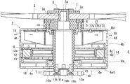
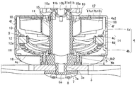
第一ケース体4aの軸方向端面4a1には、吸気用開口部4eが複数箇所に設けられている。この吸気用開口部4eより軸方向に吸気されて固定子コア12及びコイル13(固定子9)を冷却するようになっている。第二ケース体4bの軸方向内端面4b1には、フィン17がねじ17aにより一体に組み付けられている。フィン17は、軸方向内端面4b1にベース板17bを重ねてねじ止めして組み付けられる。ベース板17bには径方向に延設された羽板17cが周方向で複数枚起立形成されている。また、第二ケース体4bの羽板17cの外周側先端部と対向する側面部には、排気用開口部4fが設けられている。フィン17が回転すると吸気用開口部4eより軸方向に吸気された空気を径方向外側に向かって送り出し排気用開口部4fから排気するようになっている。
At the axial end face 4a1 of the first case body 4a, intake openings 4e are provided at a plurality of places. The stator core 12 and the coil 13 (the stator 9) are cooled by being axially sucked from the intake opening 4e. Fins 17 are integrally assembled to the axially inner end surface 4b1 of the second case body 4b by screws 17a. The fins 17 are assembled by screwing together the base plate 17b on the axially inner end surface 4b1. A plurality of vanes 17c extending in the radial direction are erected on the base plate 17b in the circumferential direction. Further, an exhaust opening 4f is provided on a side surface facing the outer peripheral tip end of the wing plate 17c of the second case body 4b. When the fins 17 rotate, the air taken in in the axial direction from the intake opening 4e is sent radially outward and exhausted from the exhaust opening 4f.
上記吸気用開口部4e及び排気用開口部4fは、所定の開口径を有する通気性撥水性を有するフィルター材18(例えばナイロン66等のメッシュシート)により各々覆われている(図3参照)。フィルター材18は、第一ケース体4a,第二ケース体4bの内周面に接着等により固定されている。フィルター材18の開口径(例えば一辺が77μmの矩形孔)は、固定子極歯12aと回転子マグネット4dの隙間(例えば160μm)より小さいものが好適に用いられる。これにより、塵埃等の異物が固定子極歯12aと回転子マグネット4dとの隙間に挟まってモータロックが生じるのを防ぐことができるうえに、吸気用開口部4e及び排気用開口部4fの防水防滴機能も担保することができる。
The intake opening 4e and the exhaust opening 4f are covered with a breathable water-repellent filter material 18 (for example, a mesh sheet such as nylon 66) having a predetermined opening diameter (see FIG. 3). The filter material 18 is fixed to the inner peripheral surface of the first case body 4a and the second case body 4b by adhesion or the like. The opening diameter of the filter material 18 (for example, a rectangular hole having a side of 77 μm) is preferably smaller than the gap (for example, 160 μm) between the stator pole teeth 12a and the rotor magnet 4d. As a result, foreign matter such as dust can be prevented from being caught by the gap between the stator pole teeth 12a and the rotor magnet 4d to cause the motor lock, and the waterproof of the intake opening 4e and the exhaust opening 4f A drip-proof function can also be secured.
尚、吸気用開口部4eを覆うフィルター材18は、接着等で固定されていてもよいが、例えば図示しないアタッチメントを介して交換可能に設けられていることが望ましい。これにより吸気側開口部4eを覆うフィルター材18は、外気を吸気する際に塵埃や異物を除去するため汚れ易く、フィルター機能が低下しやすいため、メンテナンス作業がし易くなる。また、フィルター材18は、メッシュシート材に限らずスポンジ等の多孔質シート材であってもよい。また、材質は樹脂材であっても金属材であっていずれでもよい。
The filter material 18 covering the intake opening 4e may be fixed by adhesion or the like, but it is desirable that the filter material 18 be exchangeably provided, for example, through an attachment (not shown). As a result, the filter material 18 covering the intake side opening 4e is easily contaminated because dust and foreign matter are removed when the outside air is taken in, and the filter function is apt to be deteriorated, which facilitates maintenance work. The filter material 18 is not limited to the mesh sheet material and may be a porous sheet material such as a sponge. Further, the material may be either a resin material or a metal material.
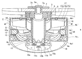
回転子14と共に回転ケース体4が回転すると、吸気側開口部4eより撥水性フィルター材18を介して軸方向に吸気して固定子コア12を経てフィン17により径方向外側に向かって排気用開口部4fを介して排気される。
これにより、全天候型モータ2が始動すると、図2の矢印に示すように、回転ケース体4の吸気側開口部4eよりフィルター材18を介して吸気し固定子コア12のコイル13を冷却してフィン17の回転により熱気を径方向外側に向かって送り出しフィルター材18を介して排気用開口部4fから排気するので、熱放散性を高めてモータ性能を維持しつつフィルター材18によって異物や水の侵入も防げる。特に、フィルター材18の存在と共に軸方向下方に設けられた吸気用開口部4eより吸気し、それより軸方向上方の径方向外側に設けられた排気用開口部4fより排気されるので、いずれの開口部に対しても水が侵入し難く防滴性能を高めることができる。 When therotary case 4 is rotated together with the rotor 14, it is axially sucked from the intake side opening 4e through the water repellent filter material 18, passes through the stator core 12, and is discharged radially outward by the fins 17. Exhausted through the part 4f.
Thereby, when the all-weather type motor 2 starts up, as shown by the arrow in FIG. 2, the air is taken in through the filter material 18 from the intake side opening 4 e of the rotating case 4 to cool the coil 13 of the stator core 12. Since the hot air is discharged radially outward by rotation of the fins 17 and exhausted from the exhaust opening 4f through the filter material 18, the filter material 18 improves the heat dissipation property and maintains the motor performance while the filter material 18 removes foreign matter and water It can also prevent intrusion. In particular, since the air is taken in through the intake opening 4e provided axially downward with the presence of the filter material 18 and exhausted through the exhaust opening 4f provided radially outward on the axial direction therefrom, Water is less likely to enter the opening, and the drip-proof performance can be enhanced.
これにより、全天候型モータ2が始動すると、図2の矢印に示すように、回転ケース体4の吸気側開口部4eよりフィルター材18を介して吸気し固定子コア12のコイル13を冷却してフィン17の回転により熱気を径方向外側に向かって送り出しフィルター材18を介して排気用開口部4fから排気するので、熱放散性を高めてモータ性能を維持しつつフィルター材18によって異物や水の侵入も防げる。特に、フィルター材18の存在と共に軸方向下方に設けられた吸気用開口部4eより吸気し、それより軸方向上方の径方向外側に設けられた排気用開口部4fより排気されるので、いずれの開口部に対しても水が侵入し難く防滴性能を高めることができる。 When the
Thereby, when the all-
上記構成によれば、全天候型モータ2を構成する固定子9及び回転子14が回転ケース体4に軸方向両端及び外周面を覆われているのでモータ2内に異物が侵入し難くしかも吸気側開口部4e及び排気用開口部4fはフィルター材18で覆われているため、防塵防滴効果が高い。
また、全天候型モータ2を起動すると回転子14と一体化された回転ケース体4が回転し、回転ケース体4内に設けられたフィン17が回転することで、回転ケース体4の軸方向一端側の吸気用開口部4eより吸気しモータ内で発生した熱気を軸方向他端側のフィン17により径方向外側に送り出して排気用開口部4fより排気することができる。
これにより、モータの熱放散性を高めることでモータ性能の低下を防ぎ、かつ防塵防滴性能を高めてモータ性能を維持することができる全天候型モータ2を提供することができる。 According to the above configuration, since both thestator 9 and the rotor 14 constituting the all-weather motor 2 are covered with the rotating case body 4 in the axial direction at both ends and the outer peripheral surface, foreign matter hardly penetrates into the motor 2. Since the opening 4 e and the exhaust opening 4 f are covered with the filter material 18, the dustproof and drip-proof effect is high.
Further, when the all-weather motor 2 is started, the rotation case 4 integrated with the rotor 14 is rotated, and the fins 17 provided in the rotation case 4 are rotated. It is possible to take in air from the air intake opening 4e on the side and send out the hot air generated inside the motor radially outward by the fin 17 on the other axial end side and exhaust it from the air discharge opening 4f.
As a result, it is possible to provide an all-weather type motor 2 capable of preventing the motor performance from being degraded by enhancing the heat dissipation of the motor and enhancing the dustproof and drip-proof performance to maintain the motor performance.
また、全天候型モータ2を起動すると回転子14と一体化された回転ケース体4が回転し、回転ケース体4内に設けられたフィン17が回転することで、回転ケース体4の軸方向一端側の吸気用開口部4eより吸気しモータ内で発生した熱気を軸方向他端側のフィン17により径方向外側に送り出して排気用開口部4fより排気することができる。
これにより、モータの熱放散性を高めることでモータ性能の低下を防ぎ、かつ防塵防滴性能を高めてモータ性能を維持することができる全天候型モータ2を提供することができる。 According to the above configuration, since both the
Further, when the all-
As a result, it is possible to provide an all-
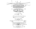
上述した全天候型モータ2を含む無人航空機の組立て構成の一例について図3及び図4を参照して説明する。予め、回転ケース体4の第二ケース体4bに台座板5が複数のねじ6により固定する(図3参照)。台座板5に突設された軸部5aをプロペラ3の軸孔3aに挿通してプロペラ3を台座板5上に組み付け、軸孔7aに挿通して止め板7をプロペラ3上に重ね合わせてねじ8により一体に固定しておく。また、第一ケース体4aの吸気用開口部4eの外面側、第二ケース体4bの排気用開口部4fの内面側を覆ってフィルター材18を各々接着しておく(図4参照)。
An example of an assembly configuration of the unmanned aerial vehicle including the all-weather motor 2 described above will be described with reference to FIGS. 3 and 4. The pedestal plate 5 is fixed in advance to the second case body 4b of the rotating case body 4 by a plurality of screws 6 (see FIG. 3). Insert the shaft 5a protruding from the base plate 5 into the shaft hole 3a of the propeller 3 to assemble the propeller 3 on the base plate 5, insert it into the shaft hole 7a and overlap the stop plate 7 on the propeller 3 It is integrally fixed by the screw 8. Further, the filter material 18 is adhered to cover the outer surface side of the intake opening 4e of the first case body 4a and the inner surface side of the exhaust opening 4f of the second case body 4b (see FIG. 4).
取付ベース10にねじ止めされた軸受ハウジング11には固定子9が一体に組み付けられている。また、軸受ハウジング11の長手方向両端部には第一軸受15及び第二軸受16が各々組み付けられている。第一ケース体4aは第一軸受15を介して軸受ハウジング11に対して回転可能に支持され、第二ケース体4bは第二軸受16を介して軸受ハウジング11に対して回転可能に支持される(図3参照)。
A stator 9 is integrally assembled to a bearing housing 11 screwed to a mounting base 10. Further, the first bearing 15 and the second bearing 16 are respectively assembled to both end portions in the longitudinal direction of the bearing housing 11. The first case body 4 a is rotatably supported by the bearing housing 11 via the first bearing 15, and the second case body 4 b is rotatably supported by the bearing housing 11 via the second bearing 16. (See Figure 3).
図4に示すように、第二ケース体4bの軸方向内端面4b1にフィン17をねじ17aにより一体にねじ止めして組み付ける。また、回転子マグネット4dを支持するバックヨーク4cは、第一ケース体4a及び第二ケース体4bの開口端に各々嵌め合わせて組み付けられる。そして、第一ケース体4aとバックヨーク4cとが接着固定され、第二ケース体4bとバックヨーク4cとの重なり部分に固定ねじ19をねじ篏合させて、第一ケース体4aと第二ケース体4bがバックヨーク4cを介して一体に組み付けられる。
As shown in FIG. 4, the fins 17 are integrally screwed to the axially inner end surface 4b1 of the second case body 4b by screws 17a. Further, the back yoke 4c supporting the rotor magnet 4d is assembled by being fitted to the open end of the first case body 4a and the second case body 4b. Then, the first case body 4a and the back yoke 4c are adhesively fixed, and the fixing screw 19 is screwed into the overlapping portion of the second case body 4b and the back yoke 4c, whereby the first case body 4a and the second case The body 4b is assembled integrally via the back yoke 4c.
図2に示すように全天候型モータ2を起動すると、回転子14と一体化された回転ケース体4が回転する。このとき、回転ケース体4内のフィン17が回転することで、回転ケース体4の軸方向一端側の吸気用開口部4eより軸方向に吸気しモータ内で発生した熱気を軸方向他端側のフィン17により径方向外側に送り出して排気用開口部4fより排気することができる。
As shown in FIG. 2, when the all-weather motor 2 is started, the rotating case 4 integrated with the rotor 14 is rotated. At this time, the fins 17 in the rotating case 4 rotate, so that the hot air generated in the motor is axially sucked from the intake opening 4 e at one axial end of the rotating case 4 at the other axial end. The fins 17 can be fed radially outward to exhaust air from the exhaust opening 4f.
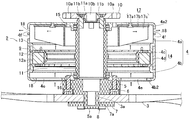
次に上記全天候型モータ2の変形例を図5及び図6に示す。上記図1乃至図4に示す実施形態と同一部材には同一番号を付して説明を援用するものとし、異なる構成を中心に説明する。上述した全天候型モータ2は、無人航空機の駆動源として用いられ、回転ケース体4の第一ケース体4aと第二ケース体4bを天地が逆向きに配置、より具体的には取付ベース10とプロペラ3を天地逆向きにして使用することもできる。
Next, a modified example of the all-weather type motor 2 is shown in FIG. 5 and FIG. The same members as those in the embodiment shown in FIGS. 1 to 4 are denoted by the same reference numerals, and the description will be incorporated, and different configurations will be mainly described. The all-weather motor 2 described above is used as a drive source for an unmanned aerial vehicle, and the first case body 4a and the second case body 4b of the rotating case body 4 are arranged with their tops and bottoms facing each other. It is also possible to use the propeller 3 upside down.
図5において第二ケース体4bの軸方向端面4b2には、吸気用開口部4eが複数箇所に設けられている。この吸気用開口部4eより軸方向に吸気されて固定子コア12及びコイル13(固定子9)を冷却するようになっている。第一ケース体4aの軸方向内端面4a2には、フィン17がねじ17aにより一体に組み付けられている。フィン17は、軸方向内端面4a2にベース板17bを重ねてねじ止めして組み付けられる。ベース板17bには径方向に延設された羽板17cが周方向で複数枚起立形成されている。
また、第一ケース体4aの羽板17cの外周側先端部と対向する側面部には、排気用開口部4fが設けられている。フィン17が回転すると吸気用開口部4eより軸方向に吸気された空気を周方向に向かって送り出し排気用開口部4fから排気するようになっている。
これにより、塵埃等の異物が固定子極歯12aと回転子マグネット4dとの隙間に挟まってモータロックが生じるのを防ぐことができるうえに、吸気用開口部4e及び排気用開口部4fの防水防滴機能も担保することができる。 In FIG. 5, at the axial end face 4b2 of thesecond case body 4b, intake openings 4e are provided at a plurality of places. The stator core 12 and the coil 13 (the stator 9) are cooled by being axially sucked from the intake opening 4e. Fins 17 are integrally assembled to the axially inner end surface 4a2 of the first case body 4a by screws 17a. The fins 17 are assembled by screwing the base plate 17b on the axially inner end surface 4a2. A plurality of vanes 17c extending in the radial direction are erected on the base plate 17b in the circumferential direction.
In addition, anexhaust opening 4f is provided on the side surface of the first case body 4a that faces the outer peripheral tip end of the wing plate 17c. When the fins 17 rotate, the air taken in in the axial direction from the intake opening 4e is sent out in the circumferential direction and exhausted from the exhaust opening 4f.
As a result, foreign matter such as dust can be prevented from being caught by the gap between thestator pole teeth 12a and the rotor magnet 4d to cause the motor lock, and the waterproof of the intake opening 4e and the exhaust opening 4f A drip-proof function can also be secured.
また、第一ケース体4aの羽板17cの外周側先端部と対向する側面部には、排気用開口部4fが設けられている。フィン17が回転すると吸気用開口部4eより軸方向に吸気された空気を周方向に向かって送り出し排気用開口部4fから排気するようになっている。
これにより、塵埃等の異物が固定子極歯12aと回転子マグネット4dとの隙間に挟まってモータロックが生じるのを防ぐことができるうえに、吸気用開口部4e及び排気用開口部4fの防水防滴機能も担保することができる。 In FIG. 5, at the axial end face 4b2 of the
In addition, an
As a result, foreign matter such as dust can be prevented from being caught by the gap between the
上述した全天候型モータ2を含む無人航空機の組立て構成の一例について図6を参照して説明する。予め、回転ケース体4を構成する第二ケース体4bに台座板5が複数のねじ6により固定する。台座板5に突設された軸部5aをプロペラ3の軸孔3aに挿通してプロペラ3を台座板5上に組み付け、軸孔7aに挿通して止め板7をプロペラ3上に重ね合わせてねじ8により一体に固定しておく。また、第二ケース体4bの吸気用開口部4eの外面側、第一ケース体4aの排気用開口部4fの内面側を覆ってフィルター材18を各々接着しておく。
An example of the assembly configuration of the unmanned aerial vehicle including the all-weather motor 2 described above will be described with reference to FIG. The base plate 5 is fixed in advance to the second case body 4 b constituting the rotating case body 4 by a plurality of screws 6. Insert the shaft 5a protruding from the base plate 5 into the shaft hole 3a of the propeller 3 to assemble the propeller 3 on the base plate 5, insert it into the shaft hole 7a and overlap the stop plate 7 on the propeller 3 It is integrally fixed by the screw 8. Further, the filter material 18 is adhered to cover the outer surface side of the intake opening 4e of the second case body 4b and the inner surface side of the exhaust opening 4f of the first case body 4a.
取付ベース10にねじ止めされた軸受ハウジング11には固定子9が一体に組み付けられている。また、軸受ハウジング11の長手方向両端部には第一軸受15及び第二軸受16が各々組み付けられている。第一ケース体4aは第一軸受15を介して軸受ハウジング11に対して回転可能に支持され、第二ケース体4bは第二軸受16を介して軸受ハウジング11に対して回転可能に支持される。この場合、第一軸受15は、シール型ベアリングを用いると水の侵入を防ぐことができ、好適である。
A stator 9 is integrally assembled to a bearing housing 11 screwed to a mounting base 10. Further, the first bearing 15 and the second bearing 16 are respectively assembled to both end portions in the longitudinal direction of the bearing housing 11. The first case body 4 a is rotatably supported by the bearing housing 11 via the first bearing 15, and the second case body 4 b is rotatably supported by the bearing housing 11 via the second bearing 16. . In this case, it is preferable to use a seal type bearing as the first bearing 15 can prevent the entry of water.
第一ケース体4aの軸方向内端面4a2にフィン17をねじ17aにより一体にねじ止めして組み付ける。また、回転子マグネット4dを支持するバックヨーク4cは、第一ケース体4a及び第二ケース体4bの開口端に各々嵌め合わせて組み付けられる。そして、第一ケース体4aとバックヨーク4cとが接着固定され、第二ケース体4bとバックヨーク4cの重なり部分に固定ねじ19(図1参照)をねじ篏合させて、第一ケース体4aと第二ケース体4bがバックヨーク4cを介して一体に組み付けられる。
The fins 17 are integrally screwed to the axially inner end surface 4a2 of the first case body 4a with screws 17a and assembled. Further, the back yoke 4c supporting the rotor magnet 4d is assembled by being fitted to the open end of the first case body 4a and the second case body 4b. Then, the first case body 4a and the back yoke 4c are adhesively fixed, and the fixing screw 19 (see FIG. 1) is screwed into the overlapping portion of the second case body 4b and the back yoke 4c to form the first case body 4a. The second case body 4b is integrally assembled via the back yoke 4c.
図5に示すように全天候型モータ2を起動すると、回転子14と一体化された回転ケース体4が回転する。このとき、回転ケース体4内のフィン17が回転することで、回転ケース体4の軸方向一端側の吸気用開口部4eより軸方向に吸気しモータ2内で発生した熱気を軸方向他端側のフィン17により径方向外側に送り出して排気用開口部4fより排気することができる。
これにより、モータの熱放散性を高めることでモータ性能の低下を防ぎ、かつ防塵防滴性能を高めて異物の侵入を防ぐことでモータ性能を維持することができる全天候型モータ2を提供することができる。 When the all-weather motor 2 is activated as shown in FIG. 5, the rotating case 4 integrated with the rotor 14 is rotated. At this time, the fins 17 in the rotating case 4 rotate, so that the hot air generated in the motor 2 is axially sucked from the intake opening 4e at one axial end of the rotating case 4 and the other end in the axial direction It is possible to send out radially outward by the side fins 17 and exhaust air from the exhaust opening 4f.
Accordingly, it is possible to provide an all-weather motor 2 capable of preventing motor performance deterioration by enhancing the heat dissipation of the motor and maintaining the motor performance by enhancing the dustproof and drip-proof performance to prevent the entry of foreign matter Can.
これにより、モータの熱放散性を高めることでモータ性能の低下を防ぎ、かつ防塵防滴性能を高めて異物の侵入を防ぐことでモータ性能を維持することができる全天候型モータ2を提供することができる。 When the all-
Accordingly, it is possible to provide an all-
また、図2に示す全天候型モータ2と図5に示す全天候型モータ2を無人航空機の機体フレームの上下に取付べース10を対向させて組み付けることもできる。この場合、プロペラ3(全天候型モータ2)の回転方向は互いに逆向きになるので、互いに正逆回転駆動され、機体フレームに作用するモータ振動が互いに逆向きとなって打ち消し合うので、推力を2倍にしても低振動化を図ることができる。また、図2と図5に示す全天候型モータ2を、機体フレームを介して上下に取り付けても、各回転ケース体4には、軸方向下方の吸気用開口部4eより吸気して軸方向上部側方の排気用開口部4fより排気するので、防塵防滴性能を高めて異物や水の侵入を防ぐことでモータ性能を維持することができる。
Further, it is possible to assemble the all-weather motor 2 shown in FIG. 2 and the all-weather motor 2 shown in FIG. 5 such that the mounting bases 10 face the upper and lower sides of the body frame of the unmanned aircraft. In this case, since the propellers 3 (all-weather type motor 2) rotate in opposite directions, they are driven to rotate in forward and reverse directions, and the motor vibrations acting on the body frame cancel each other in opposite directions. Vibration can be reduced even by doubling. Also, even if the all-weather motor 2 shown in FIGS. 2 and 5 is mounted vertically through the machine frame, each rotary case 4 is sucked from the intake opening 4e axially lower to be axially upper Since the air is exhausted from the side exhaust opening 4f, the motor performance can be maintained by enhancing the dustproof and drip-proof performance to prevent the entry of foreign matter and water.
上述した全天候型モータ2はDCブラシレスレスモータを用いたが、DCブラシ付きモータ等他のモータであってもよい。
また、回転ケース体4にねじ止め固定されていたフィン17は、回転ケース体4(第一ケース体4a又は第二ケース体4b)と一体に形成されていても良い。
また、吸気用開口部4eは、上述したように回転ケース体4が有底筒状体の場合には防滴性を考慮すると軸方向下端面が好ましいが、回転ケース体4に端面が存在しない曲面となる場合には、軸方向下方面に設けられることが望ましい。
また、フィルター材18は、撥水性、通気性、防塵性を確保できるものであれば、樹脂製多孔質材、金属メッシュ材等、多様な材質並びに多様な形態のものを用いることができる。
更には、上述した実施形態では、全天候型モータ2は無人航空機用の駆動源として用いた場合について説明したが、用途はこれに限定されるものではなく、屋外で使用される他の用途の駆動源としても適用することができる。
Although the all-weather motor 2 described above uses a DC brushless motor, it may be another motor such as a DC brush motor.
Further, thefins 17 screwed to the rotating case 4 may be formed integrally with the rotating case 4 (the first case 4 a or the second case 4 b).
Further, as described above, when therotary case body 4 is a cylindrical body with a bottom, as described above, the lower end face in the axial direction is preferable in view of drip-proof property, but no end face exists in the rotary case body 4 In the case of a curved surface, it is desirable to be provided on the axially lower surface.
Thefilter material 18 may be made of various materials and in various forms such as resin porous materials and metal mesh materials as long as it can ensure water repellency, air permeability and dust resistance.
Furthermore, in the embodiment described above, the all-weather motor 2 has been described as a drive source for an unmanned aerial vehicle, but the application is not limited to this, and the drive for other applications used outdoors It can also be applied as a source.
また、回転ケース体4にねじ止め固定されていたフィン17は、回転ケース体4(第一ケース体4a又は第二ケース体4b)と一体に形成されていても良い。
また、吸気用開口部4eは、上述したように回転ケース体4が有底筒状体の場合には防滴性を考慮すると軸方向下端面が好ましいが、回転ケース体4に端面が存在しない曲面となる場合には、軸方向下方面に設けられることが望ましい。
また、フィルター材18は、撥水性、通気性、防塵性を確保できるものであれば、樹脂製多孔質材、金属メッシュ材等、多様な材質並びに多様な形態のものを用いることができる。
更には、上述した実施形態では、全天候型モータ2は無人航空機用の駆動源として用いた場合について説明したが、用途はこれに限定されるものではなく、屋外で使用される他の用途の駆動源としても適用することができる。
Although the all-
Further, the
Further, as described above, when the
The
Furthermore, in the embodiment described above, the all-
Claims (5)
- 取付ベースと、
前記取付ベースに一体に組み付けられた軸受ハウジングと、
前記軸受ハウジングに一体に組み付けられた固定子コアを有する固定子と、
前記固定子コアに対向して支持された回転子マグネットを有し前記軸受ハウジングに軸受を介して回転可能に支持された回転子と、を備え、
前記回転子は、前記固定子の外周側及び前記軸受ハウジングの軸方向両端側を覆うと共に、軸方向一端側に吸気用開口部を有し軸方向他端側に排気用開口部を有する回転ケース体と、前記回転ケース体内に軸方向他端側に設けられたフィンと、を有しており、前記吸気用開口部及び前記排気用開口部は、所定の開口径を有するフィルター材で各々覆われていることを特徴とする全天候型モータ。 Mounting base,
A bearing housing integrally assembled to the mounting base;
A stator having a stator core integrally assembled to the bearing housing;
And a rotor rotatably supported by the bearing housing via a bearing and having a rotor magnet supported to face the stator core.
The rotor covers the outer peripheral side of the stator and both axial end sides of the bearing housing, and has an intake opening at one axial end and an exhaust opening at the other axial end. And a fin provided on the other end side in the axial direction in the rotating case, and the intake opening and the exhaust opening are respectively covered with a filter material having a predetermined opening diameter. All-weather motor characterized by being - 前記回転ケース体の前記軸方向一端側に設けられた前記吸気側開口部より前記フィルター材を介して軸方向に吸気し、前記回転ケース体の軸方向他端内面に設けられた前記フィンにより径方向外側に向かって送り出して前記フィルター材を介して前記排気用開口部から排気される請求項1記載の全天候型モータ。 The air is taken in in the axial direction through the filter material from the intake side opening portion provided on the one end side in the axial direction of the rotation case body, and the diameter is provided by the fins provided on the inner surface of the other end in the axial direction of the rotation case body The all-weather motor according to claim 1, wherein the all-weather motor is discharged outward in the direction and exhausted from the exhaust opening through the filter material.
- 前記フィルター材の開口径は、固定子極歯と前記回転子マグネットの隙間寸法より小さいものが用いられる請求項1又は請求項2記載の全天候型モータ。 3. The all-weather motor according to claim 1, wherein an opening diameter of the filter material is smaller than a clearance between stator pole teeth and the rotor magnet.
- 前記吸気用開口部を覆う前記フィルター材は交換可能に設けられている請求項1乃至請求項3のいずれかに記載の全天候型モータ。 The all-weather motor according to any one of claims 1 to 3, wherein the filter material covering the intake opening is exchangeably provided.
- 前記回転ケース体の軸方向下方に設けられた前記吸気用開口部より吸気し、それより軸方向上方の径方向外側に設けられた前記排気用開口部より排気される請求項1乃至請求項4のいずれか1項記載の全天候型モータ。
The air is taken in from the intake opening provided in the axial lower side of the rotating case body, and exhausted from the exhaust opening provided in the radial direction outer side in the axial upper direction therefrom. All-weather motor according to any one of the above.
Priority Applications (3)
| Application Number | Priority Date | Filing Date | Title |
|---|---|---|---|
| US16/605,147 US20210167658A1 (en) | 2017-09-20 | 2018-05-31 | All-weather motor |
| EP18858616.8A EP3605802A4 (en) | 2017-09-20 | 2018-05-31 | All-weather motor |
| CN201880045877.9A CN110892612A (en) | 2017-09-20 | 2018-05-31 | All-weather motor |
Applications Claiming Priority (2)
| Application Number | Priority Date | Filing Date | Title |
|---|---|---|---|
| JP2017180162A JP6644039B2 (en) | 2017-09-20 | 2017-09-20 | All-weather motor |
| JP2017-180162 | 2017-09-20 |
Publications (1)
| Publication Number | Publication Date |
|---|---|
| WO2019058647A1 true WO2019058647A1 (en) | 2019-03-28 |
Family
ID=65810722
Family Applications (1)
| Application Number | Title | Priority Date | Filing Date |
|---|---|---|---|
| PCT/JP2018/020968 WO2019058647A1 (en) | 2017-09-20 | 2018-05-31 | All-weather motor |
Country Status (5)
| Country | Link |
|---|---|
| US (1) | US20210167658A1 (en) |
| EP (1) | EP3605802A4 (en) |
| JP (1) | JP6644039B2 (en) |
| CN (1) | CN110892612A (en) |
| WO (1) | WO2019058647A1 (en) |
Cited By (1)
| Publication number | Priority date | Publication date | Assignee | Title |
|---|---|---|---|---|
| NO20211451A1 (en) * | 2021-12-01 | 2023-06-02 | Alva Ind As | Electric motor with integrated cooling |
Families Citing this family (9)
| Publication number | Priority date | Publication date | Assignee | Title |
|---|---|---|---|---|
| JP7238674B2 (en) * | 2019-07-30 | 2023-03-14 | 株式会社デンソー | thrust generator |
| CN112838719A (en) * | 2020-04-28 | 2021-05-25 | 东莞质研工业设计服务有限公司 | Application method of new energy automobile motor with back flushing self-cleaning function |
| WO2021250793A1 (en) * | 2020-06-09 | 2021-12-16 | 株式会社ナイルワークス | Flight vehicle, flight vehicle system, flight vehicle control method, and manipulator |
| CN112407310B (en) * | 2020-11-03 | 2022-05-20 | 国网浙江省电力有限公司衢州供电公司 | Unmanned aerial vehicle with small wind resistance and strong cruising ability and control method thereof |
| CN112332587A (en) * | 2020-11-04 | 2021-02-05 | 中煤科工集团上海有限公司 | Explosion-proof motor shell suitable for inspection unmanned aerial vehicle, assembly method of explosion-proof motor shell and unmanned aerial vehicle |
| JP2023053770A (en) * | 2021-10-01 | 2023-04-13 | ミネベアミツミ株式会社 | motor |
| US20230246513A1 (en) * | 2022-01-28 | 2023-08-03 | Flir Unmanned Aerial Systems Ulc | Electric motor cooling systems and methods |
| JP2023133000A (en) * | 2022-03-11 | 2023-09-22 | 株式会社デンソー | Magnetic foreign matter removal device, brushless motor, and propulsion device |
| CN117294076B (en) * | 2023-11-27 | 2024-02-20 | 南昌三瑞智能科技股份有限公司 | Motor cooling system and unmanned aerial vehicle power device |
Citations (9)
| Publication number | Priority date | Publication date | Assignee | Title |
|---|---|---|---|---|
| JPS5363610U (en) * | 1976-10-26 | 1978-05-29 | ||
| JPS60186853U (en) * | 1984-05-22 | 1985-12-11 | 日産自動車株式会社 | Motor with dustproof filter |
| JPH05328687A (en) * | 1992-05-20 | 1993-12-10 | Toshiba Corp | Outer-rotor motor |
| JPH0833266A (en) * | 1994-07-15 | 1996-02-02 | Toshiba Corp | Dynamic pressure bearing motor and scanner motor for driving polygon mirror |
| JP2000014086A (en) * | 1998-06-22 | 2000-01-14 | Nissan Motor Co Ltd | Cooling structure for multilayered motor |
| JP2003009487A (en) * | 2001-06-26 | 2003-01-10 | Kokusan Denki Co Ltd | Outer rotor type magnetogenerator with regulator |
| JP2009290981A (en) | 2008-05-29 | 2009-12-10 | Nippon Densan Corp | Waterproofing structure of electric motor |
| JP2017017983A (en) | 2015-07-01 | 2017-01-19 | 周 文三 | Heat dissipation motor |
| JP2017017892A (en) * | 2015-07-02 | 2017-01-19 | 株式会社プロドローン | Motor housing for multicopter and waterproof motor using the same |
Family Cites Families (7)
| Publication number | Priority date | Publication date | Assignee | Title |
|---|---|---|---|---|
| US4766337A (en) * | 1987-05-21 | 1988-08-23 | Magnetek, Inc. | Open drip-proof machinery cooling system using totally enclosed type bearing brackets |
| JPH05344682A (en) * | 1992-06-04 | 1993-12-24 | Toshiba Corp | Outer rotor motor |
| JP2002010574A (en) * | 2000-06-19 | 2002-01-11 | Kokusan Denki Co Ltd | Magnet-type outer-rotor dynamoelectric machine |
| JP4951777B2 (en) * | 2006-06-21 | 2012-06-13 | 並木精密宝石株式会社 | Driving motor for servo unit for radio control |
| CN101951091B (en) * | 2010-09-09 | 2012-04-11 | 中国科学院长春光学精密机械与物理研究所 | Double-rotor multi-pole motor of micro unmanned aerial vehicle |
| ES2773141T3 (en) * | 2014-10-27 | 2020-07-09 | Guangzhou Xaircraft Tech Co Ltd | Rotary-Wing Aircraft and Assembly and Disassembly Structure for Foot and Cell Support of Rotary-Wing Aircraft Aircraft |
| JP2016101008A (en) * | 2014-11-21 | 2016-05-30 | 株式会社東芝 | Rotary electric machine |
-
2017
- 2017-09-20 JP JP2017180162A patent/JP6644039B2/en active Active
-
2018
- 2018-05-31 EP EP18858616.8A patent/EP3605802A4/en not_active Withdrawn
- 2018-05-31 WO PCT/JP2018/020968 patent/WO2019058647A1/en unknown
- 2018-05-31 CN CN201880045877.9A patent/CN110892612A/en active Pending
- 2018-05-31 US US16/605,147 patent/US20210167658A1/en not_active Abandoned
Patent Citations (9)
| Publication number | Priority date | Publication date | Assignee | Title |
|---|---|---|---|---|
| JPS5363610U (en) * | 1976-10-26 | 1978-05-29 | ||
| JPS60186853U (en) * | 1984-05-22 | 1985-12-11 | 日産自動車株式会社 | Motor with dustproof filter |
| JPH05328687A (en) * | 1992-05-20 | 1993-12-10 | Toshiba Corp | Outer-rotor motor |
| JPH0833266A (en) * | 1994-07-15 | 1996-02-02 | Toshiba Corp | Dynamic pressure bearing motor and scanner motor for driving polygon mirror |
| JP2000014086A (en) * | 1998-06-22 | 2000-01-14 | Nissan Motor Co Ltd | Cooling structure for multilayered motor |
| JP2003009487A (en) * | 2001-06-26 | 2003-01-10 | Kokusan Denki Co Ltd | Outer rotor type magnetogenerator with regulator |
| JP2009290981A (en) | 2008-05-29 | 2009-12-10 | Nippon Densan Corp | Waterproofing structure of electric motor |
| JP2017017983A (en) | 2015-07-01 | 2017-01-19 | 周 文三 | Heat dissipation motor |
| JP2017017892A (en) * | 2015-07-02 | 2017-01-19 | 株式会社プロドローン | Motor housing for multicopter and waterproof motor using the same |
Non-Patent Citations (1)
| Title |
|---|
| See also references of EP3605802A4 |
Cited By (2)
| Publication number | Priority date | Publication date | Assignee | Title |
|---|---|---|---|---|
| NO20211451A1 (en) * | 2021-12-01 | 2023-06-02 | Alva Ind As | Electric motor with integrated cooling |
| NO347274B1 (en) * | 2021-12-01 | 2023-08-21 | Alva Ind As | Electric motor with integrated cooling |
Also Published As
| Publication number | Publication date |
|---|---|
| EP3605802A1 (en) | 2020-02-05 |
| US20210167658A1 (en) | 2021-06-03 |
| JP6644039B2 (en) | 2020-02-12 |
| JP2019057977A (en) | 2019-04-11 |
| CN110892612A (en) | 2020-03-17 |
| EP3605802A4 (en) | 2020-04-22 |
Similar Documents
| Publication | Publication Date | Title |
|---|---|---|
| WO2019058647A1 (en) | All-weather motor | |
| JP4291846B2 (en) | Fan motor | |
| US11527930B2 (en) | Motor for drone and drone comprising same | |
| JP6796474B2 (en) | Brushless motor | |
| JP2006217748A (en) | Fan motor | |
| JP2008215330A (en) | Centrifugal fan | |
| JP6843688B2 (en) | Electric blower and vacuum cleaner equipped with it | |
| CN107204675B (en) | Electric power unit | |
| US20190193849A1 (en) | Motor for drone and drone including same | |
| JP4951777B2 (en) | Driving motor for servo unit for radio control | |
| WO2018029741A1 (en) | Outer rotor motor, waterproof ring member, and unmanned aircraft | |
| JP6822565B2 (en) | Electric motor and electric blower | |
| JP2021020634A (en) | Thrust force generating device | |
| US20220181931A1 (en) | Rotor for electric motor | |
| WO2011039974A2 (en) | Electric motor and working machine comprising the same | |
| JP6903036B2 (en) | Electric blower and vacuum cleaner equipped with it | |
| JP6351755B2 (en) | Actuator | |
| KR101970737B1 (en) | Motor | |
| CN219513862U (en) | Outer rotor motor | |
| JP4101607B2 (en) | Bearing with power generation function | |
| JP5375169B2 (en) | Driving motor for servo unit for radio control | |
| JP2005530946A (en) | Power generation unit cooling system | |
| JP2020112144A (en) | Electric blower and vacuum cleaner loaded with it | |
| JP2007028743A (en) | Rotor for commutator motors and power tool equipped with the same | |
| WO2018116579A1 (en) | Centrifugal blower |
Legal Events
| Date | Code | Title | Description |
|---|---|---|---|
| 121 | Ep: the epo has been informed by wipo that ep was designated in this application |
Ref document number: 18858616 Country of ref document: EP Kind code of ref document: A1 |
|
| ENP | Entry into the national phase |
Ref document number: 2018858616 Country of ref document: EP Effective date: 20191022 |
|
| NENP | Non-entry into the national phase |
Ref country code: DE |