WO2019058517A1 - Heat exchanging type ventilation system - Google Patents
Heat exchanging type ventilation system Download PDFInfo
- Publication number
- WO2019058517A1 WO2019058517A1 PCT/JP2017/034337 JP2017034337W WO2019058517A1 WO 2019058517 A1 WO2019058517 A1 WO 2019058517A1 JP 2017034337 W JP2017034337 W JP 2017034337W WO 2019058517 A1 WO2019058517 A1 WO 2019058517A1
- Authority
- WO
- WIPO (PCT)
- Prior art keywords
- air
- heat exchange
- temperature
- air supply
- path
- Prior art date
Links
Images


Classifications
-
- F—MECHANICAL ENGINEERING; LIGHTING; HEATING; WEAPONS; BLASTING
- F24—HEATING; RANGES; VENTILATING
- F24F—AIR-CONDITIONING; AIR-HUMIDIFICATION; VENTILATION; USE OF AIR CURRENTS FOR SCREENING
- F24F12/00—Use of energy recovery systems in air conditioning, ventilation or screening
- F24F12/001—Use of energy recovery systems in air conditioning, ventilation or screening with heat-exchange between supplied and exhausted air
- F24F12/006—Use of energy recovery systems in air conditioning, ventilation or screening with heat-exchange between supplied and exhausted air using an air-to-air heat exchanger
-
- F—MECHANICAL ENGINEERING; LIGHTING; HEATING; WEAPONS; BLASTING
- F24—HEATING; RANGES; VENTILATING
- F24F—AIR-CONDITIONING; AIR-HUMIDIFICATION; VENTILATION; USE OF AIR CURRENTS FOR SCREENING
- F24F11/00—Control or safety arrangements
- F24F11/0001—Control or safety arrangements for ventilation
-
- F—MECHANICAL ENGINEERING; LIGHTING; HEATING; WEAPONS; BLASTING
- F24—HEATING; RANGES; VENTILATING
- F24F—AIR-CONDITIONING; AIR-HUMIDIFICATION; VENTILATION; USE OF AIR CURRENTS FOR SCREENING
- F24F11/00—Control or safety arrangements
- F24F11/50—Control or safety arrangements characterised by user interfaces or communication
- F24F11/61—Control or safety arrangements characterised by user interfaces or communication using timers
-
- F—MECHANICAL ENGINEERING; LIGHTING; HEATING; WEAPONS; BLASTING
- F24—HEATING; RANGES; VENTILATING
- F24F—AIR-CONDITIONING; AIR-HUMIDIFICATION; VENTILATION; USE OF AIR CURRENTS FOR SCREENING
- F24F11/00—Control or safety arrangements
- F24F11/62—Control or safety arrangements characterised by the type of control or by internal processing, e.g. using fuzzy logic, adaptive control or estimation of values
- F24F11/63—Electronic processing
- F24F11/65—Electronic processing for selecting an operating mode
- F24F11/67—Switching between heating and cooling modes
-
- F—MECHANICAL ENGINEERING; LIGHTING; HEATING; WEAPONS; BLASTING
- F24—HEATING; RANGES; VENTILATING
- F24F—AIR-CONDITIONING; AIR-HUMIDIFICATION; VENTILATION; USE OF AIR CURRENTS FOR SCREENING
- F24F11/00—Control or safety arrangements
- F24F11/70—Control systems characterised by their outputs; Constructional details thereof
- F24F11/80—Control systems characterised by their outputs; Constructional details thereof for controlling the temperature of the supplied air
- F24F11/81—Control systems characterised by their outputs; Constructional details thereof for controlling the temperature of the supplied air by controlling the air supply to heat-exchangers or bypass channels
-
- F—MECHANICAL ENGINEERING; LIGHTING; HEATING; WEAPONS; BLASTING
- F24—HEATING; RANGES; VENTILATING
- F24F—AIR-CONDITIONING; AIR-HUMIDIFICATION; VENTILATION; USE OF AIR CURRENTS FOR SCREENING
- F24F13/00—Details common to, or for air-conditioning, air-humidification, ventilation or use of air currents for screening
- F24F13/08—Air-flow control members, e.g. louvres, grilles, flaps or guide plates
- F24F13/10—Air-flow control members, e.g. louvres, grilles, flaps or guide plates movable, e.g. dampers
-
- F—MECHANICAL ENGINEERING; LIGHTING; HEATING; WEAPONS; BLASTING
- F24—HEATING; RANGES; VENTILATING
- F24F—AIR-CONDITIONING; AIR-HUMIDIFICATION; VENTILATION; USE OF AIR CURRENTS FOR SCREENING
- F24F3/00—Air-conditioning systems in which conditioned primary air is supplied from one or more central stations to distributing units in the rooms or spaces where it may receive secondary treatment; Apparatus specially designed for such systems
- F24F3/044—Systems in which all treatment is given in the central station, i.e. all-air systems
-
- F—MECHANICAL ENGINEERING; LIGHTING; HEATING; WEAPONS; BLASTING
- F24—HEATING; RANGES; VENTILATING
- F24F—AIR-CONDITIONING; AIR-HUMIDIFICATION; VENTILATION; USE OF AIR CURRENTS FOR SCREENING
- F24F7/00—Ventilation
- F24F7/04—Ventilation with ducting systems, e.g. by double walls; with natural circulation
- F24F7/06—Ventilation with ducting systems, e.g. by double walls; with natural circulation with forced air circulation, e.g. by fan positioning of a ventilator in or against a conduit
- F24F7/08—Ventilation with ducting systems, e.g. by double walls; with natural circulation with forced air circulation, e.g. by fan positioning of a ventilator in or against a conduit with separate ducts for supplied and exhausted air with provisions for reversal of the input and output systems
-
- F—MECHANICAL ENGINEERING; LIGHTING; HEATING; WEAPONS; BLASTING
- F24—HEATING; RANGES; VENTILATING
- F24F—AIR-CONDITIONING; AIR-HUMIDIFICATION; VENTILATION; USE OF AIR CURRENTS FOR SCREENING
- F24F11/00—Control or safety arrangements
- F24F11/0001—Control or safety arrangements for ventilation
- F24F2011/0002—Control or safety arrangements for ventilation for admittance of outside air
-
- F—MECHANICAL ENGINEERING; LIGHTING; HEATING; WEAPONS; BLASTING
- F24—HEATING; RANGES; VENTILATING
- F24F—AIR-CONDITIONING; AIR-HUMIDIFICATION; VENTILATION; USE OF AIR CURRENTS FOR SCREENING
- F24F12/00—Use of energy recovery systems in air conditioning, ventilation or screening
- F24F12/001—Use of energy recovery systems in air conditioning, ventilation or screening with heat-exchange between supplied and exhausted air
- F24F2012/007—Use of energy recovery systems in air conditioning, ventilation or screening with heat-exchange between supplied and exhausted air using a by-pass for bypassing the heat-exchanger
-
- F—MECHANICAL ENGINEERING; LIGHTING; HEATING; WEAPONS; BLASTING
- F24—HEATING; RANGES; VENTILATING
- F24F—AIR-CONDITIONING; AIR-HUMIDIFICATION; VENTILATION; USE OF AIR CURRENTS FOR SCREENING
- F24F2110/00—Control inputs relating to air properties
- F24F2110/10—Temperature
-
- F—MECHANICAL ENGINEERING; LIGHTING; HEATING; WEAPONS; BLASTING
- F24—HEATING; RANGES; VENTILATING
- F24F—AIR-CONDITIONING; AIR-HUMIDIFICATION; VENTILATION; USE OF AIR CURRENTS FOR SCREENING
- F24F2110/00—Control inputs relating to air properties
- F24F2110/10—Temperature
- F24F2110/12—Temperature of the outside air
-
- Y—GENERAL TAGGING OF NEW TECHNOLOGICAL DEVELOPMENTS; GENERAL TAGGING OF CROSS-SECTIONAL TECHNOLOGIES SPANNING OVER SEVERAL SECTIONS OF THE IPC; TECHNICAL SUBJECTS COVERED BY FORMER USPC CROSS-REFERENCE ART COLLECTIONS [XRACs] AND DIGESTS
- Y02—TECHNOLOGIES OR APPLICATIONS FOR MITIGATION OR ADAPTATION AGAINST CLIMATE CHANGE
- Y02B—CLIMATE CHANGE MITIGATION TECHNOLOGIES RELATED TO BUILDINGS, e.g. HOUSING, HOUSE APPLIANCES OR RELATED END-USER APPLICATIONS
- Y02B30/00—Energy efficient heating, ventilation or air conditioning [HVAC]
- Y02B30/56—Heat recovery units
Definitions
- the present invention relates to a heat exchange ventilation system having a heat exchange ventilator that exchanges heat between an exhaust gas flow for discharging indoor air to the outside of the room and a charge air flow for supplying air to the room outside. is there.
- thermocontrol device for adjusting the temperature of the charge air flow by means of a temperature control device installed in the charge air path.
- Such devices include a separate type in which another device having a temperature control coil is installed on the air supply duct of the heat exchange ventilator, and an integrated type having a temperature control coil inside the heat exchange ventilator. And exist.
- Patent Document 1 discloses a total heat exchange ventilator having an air conditioning coil in the middle of an outdoor air supply passage extending from an outdoor supply port to an indoor supply port inside a casing.
- a heat exchange type ventilator having a temperature control coil for example, when ventilating and heating in the early morning of winter, when both the outdoor air temperature and the indoor air temperature are low, the total heat exchange element is between the outside air and the indoor return air. Even if the temperature is exchanged, the temperature of the air flow after the passage of all the heat exchange elements is low, so even if the temperature is adjusted by the temperature control coil, the air supplied into the room does not rise to a sufficient temperature. The condition may continue to take time to heat up, or the room may be left unheated.
- the temperature of the charge air flow after passing through the temperature adjustment coil may not decrease, and it may take time to cool the room temperature to the target temperature. Or, the room may not be cooled.
- the present invention has been made in view of the above, and includes a heat exchange ventilator and a temperature control coil, and a heat exchange ventilator system capable of efficiently adjusting the temperature of air supplied into a room.
- the purpose is to get.
- a heat exchange type ventilation system comprises a heat exchange type ventilation device, a supply air flow path for supplying outside air to the room, and room air. It is a heat exchange type ventilation system provided with an exhaust air path which exhausts to the outdoors.
- the air supply path in the apparatus which is the air supply path in the heat exchange type ventilator
- the exhaust air path which is the exhaust air path in the heat exchange type ventilator
- the heat exchange type ventilation system is disposed downstream of the heat exchange element in the air supply air path, and is provided with a temperature control coil for heating or cooling air passing through the air supply air path downstream of the heat exchange element;
- An air passage switching damper for returning air to an intermediate position on the upstream side of the temperature adjustment coil in the air supply air passage, an air passage switching damper for switching between the air supply air passage which is an air passage taking in the outside air and the reflux air supply passage;
- Air temperature sensor for detecting the temperature of the air
- return air temperature sensor for detecting the temperature of the air in the room exhausted to the outside, a control unit for controlling the operation of the heat exchange ventilator, the temperature control coil and the air path switching damper And.
- the heat exchange type ventilation system according to the present invention has a heat exchange type ventilation device and a temperature control coil, and has an effect that the temperature of air supplied into the room can be efficiently adjusted.
- the schematic diagram which simplifies and shows the structure of the heat exchange system ventilation system concerning Embodiment 1 of this invention The figure which shows the function structure in connection with control of the heat exchange system ventilation system concerning Embodiment 1 of this invention.
- a flowchart showing an example of a procedure of an air path switching operation during operation of the heat exchange ventilation system according to the first embodiment of the present invention A flowchart showing an example of the procedure of the air path switching operation during operation of the heat exchange ventilation system according to the second embodiment of the present invention
- a flowchart showing an example of a procedure of an air path switching operation during operation of the heat exchange ventilation system in the third embodiment of the present invention A flowchart showing an example of a procedure of an air path switching operation at the time of operation of the heat exchange ventilation system in the fourth embodiment of the present invention
- a flowchart showing an example of the procedure of the air path switching operation during operation of the heat exchange ventilation system according to the fifth embodiment of the present invention The schematic diagram which simplifies and shows the structure of the heat exchange system ventilation system concerning Embodiment 6 of this invention
- FIG. 1 is a schematic diagram which simplifies and shows the structure of the heat exchange system ventilation system 100 concerning Embodiment 1 of this invention.
- FIG. 2 is a diagram showing a functional configuration related to control of the heat exchange ventilation system 100 according to the first embodiment of the present invention.
- the heat exchange type ventilation system 100 is a heat exchange type ventilation system provided with an air supply path 11 for supplying outside air which is outdoor air to the room and an exhaust air path 12 for exhausting indoor air to the outside.
- the heat exchange type ventilation system 100 includes an outside air inlet 1a for taking in outside air, an air supply outlet 1b for supplying outside air to the room, an indoor air inlet 1c for taking in room air, and an exhaust outlet 1d for discharging the room air to the outside.
- the heat exchange type ventilation device 1 is provided with the heat exchange element 2 which is a total heat exchanger disposed in the inside of a housing 1e having the above.
- the heat exchange type ventilation device 1 is a heat exchange type ventilation device for air conditioning which has a heat exchange element 2 in the inside of a housing 1 e.
- the heat exchange type ventilator 1 is installed in a state of being concealed by the ceiling 52.
- the heat exchange type ventilation device 1 includes a control unit 31 attached to the outside of the housing 1 e and a remote controller 32 installed in the room 53.
- the area above the ceiling 51 is the ceiling 52
- the area below the ceiling 51 is the room 53.
- the symbol OA indicates the outdoor air
- the symbol SA indicates the supply air
- the symbol RA indicates the return air
- the symbol EA indicates the exhaust air.
- the air supply path 11 of the heat exchange type ventilation system 100 is an upstream side air supply path 11a which is upstream of the heat exchange type ventilation device 1 and is communicated with the outside, and the air supply path 11 in the heat exchange type ventilation system 1. It is divided into three, i.e., the in-apparatus supply air passage 11b and the downstream side supply air passage 11c which is downstream of the heat exchange ventilator 1 and which communicates with the room.
- the exhaust air passage 12 of the heat exchange type ventilation system 100 is an upstream side of the heat exchange type ventilator 1 and is in communication with the indoor side, and the exhaust air in the heat exchange type ventilator 1 It is divided into three: an in-apparatus exhaust air passage 12b, which is a passage 12, and a downstream-side exhaust air passage 12c which is downstream of the heat exchange ventilator 1 and which communicates with the outside.
- the heat exchange ventilator 1 includes an in-apparatus air supply passage 11b which is an air supply airflow passage 11 in the heat exchange ventilator 1 connected between the outside air suction port 1a and the air supply outlet 1b via the heat exchange element 2; And an in-apparatus exhaust air passage 12b which is an exhaust air passage 12 in the heat exchange ventilator 1 connecting the indoor air suction port 1c and the exhaust discharge port 1d via the heat exchange element 2.
- the in-device supply air passage 11b and the in-device exhaust air passage 12b are air passages independent of each other.
- the in-apparatus supply air path 11b is an air path for supplying the outside air OA into the room, and heat exchange with the outside air heat exchange front air path 11ba formed between the outside air suction port 1a and the heat exchange element 2 It has an air passage 11bb after external heat exchange formed between the element 2 and the air supply / discharge port 1b, and a heat exchange element air supply passage 11bc formed inside the heat exchange element 2.
- the in-apparatus exhaust air path 12b is an air path for exhausting the return air RA, which is room air, to the outside, and the room air heat exchange front wind formed between the room air suction port 1c and the heat exchange element 2
- the in-apparatus supply air passage 11 b and the in-apparatus exhaust air passage 12 b intersect at the heat exchange element 2.
- the air passage 11 bb after the outside air heat exchange and the air passage 12 bb after the indoor air heat exchange are partitioned by the heat exchange element 2.
- the outdoor air heat exchange front air passage 11 ba and the indoor air heat exchange front air passage 12 ba are separated by the heat exchange element 2.
- the outdoor air heat exchange front air passage 11 ba and the indoor air heat exchange after air passage 12 bb are partitioned by a flat partition wall 7.
- the indoor air heat exchange front air passage 12 ba and the outdoor air heat exchange after air passage 11 bb are partitioned by the partition wall 8.
- the heat exchange type ventilation device 1 includes an air supply blower 3 for generating a flow of the air supply flow from the outside air suction port 1a toward the air supply discharge port 1b in the apparatus air supply air passage 11b. Further, the heat exchange type ventilation device 1 is provided with the exhaust blower 4 for generating the flow of the exhaust flow from the indoor air suction port 1c to the exhaust discharge port 1d in the in-device exhaust air passage 12b.
- the air supply blower 3 is disposed in the air passage 11bb after the outside air heat exchange, and internally includes an air supply motor (not shown) for driving the air supply blower 3.
- the exhaust blower 4 is disposed in the air passage 12bb after the indoor air heat exchange, and includes an exhaust motor (not shown) for driving the exhaust blower 4 therein.
- the rotational speeds of the air supply motor and the exhaust motor change in accordance with control by the control unit 31 described later.
- an upstream air supply air passage 11a which is constituted by a duct pipe and is an outside air intake air passage for taking in outside air OA and flowing it to the heat exchange type ventilator 1.
- a downstream side air supply air passage 11c which is a supply air discharge air passage for flowing the air supply flow from the heat exchange type ventilation device 1 into the room, is connected to the air supply discharge port 1b.
- an upstream side exhaust air passage 12 a which is an indoor air suction air passage which is constituted by a duct pipe and takes in the indoor air and flows it to the heat exchange ventilator 1.
- the exhaust gas discharge port 1d is connected to a downstream side exhaust air flow path 12c which is an exhaust gas discharge air path which is constituted by a duct pipe and allows the exhaust gas flow from the heat exchange ventilator 1 to flow to the outside.
- a temperature control coil 21 provided outside the heat exchange ventilator 1 is disposed in the downstream air supply passage 11c.
- the temperature control coil 21 is a heat exchanger capable of heating or cooling the air supply flow passing through the downstream air supply air passage 11c. That is, the temperature control coil 21 is disposed downstream of the heat exchange element 2 in the air supply passage, and heats or cools the air passing through the air supply passage downstream of the heat exchange element 2.
- the operation of the temperature control coil 21 is controlled by the control unit 31 in conjunction with the heat exchange ventilator 1, and the air supply passes through the downstream air supply air passage 11 c so that the room temperature reaches the target temperature set by the user. Adjust the temperature of the air flow.
- the temperature control coil 21 heats the supplied supply air.
- the temperature control coil 21 cools the passing air, when the supplied air supplied from the heat exchange ventilator 1 passes through the temperature control coil 21.
- the symbol OA indicates outside air
- the symbol SA indicates air supply
- the symbol RA indicates return air
- the symbol EA indicates exhaust.
- the outside air OA flows from the outside air suction port 1a into the outside air heat exchange front air passage 11ba from the outside via the upstream air supply air passage 11a communicated with the outside of the building from the outside, and becomes an air supply flow.
- the air flow flowing into the outside air heat exchange front air path 11ba is the heat exchange element 2, the air path 11bb after the outside air heat exchange, the air blower 3 for air supply, the air supply outlet 1b, the downstream air supply air path 11c, and the temperature control coil 21. And, it is blown out into the room through the downstream air supply path 11c.
- the return air RA flows from the indoor air suction port 1c into the indoor air heat exchange front air passage 12ba from the room via the upstream side exhaust air passage 12a communicating with the room and becomes an exhaust flow.
- the exhaust gas flowed into the indoor air heat exchange front air passage 12ba is blown out to the outside as the exhaust air EA through the heat exchange element 2, the air passage 12bb after the indoor air heat exchange, the exhaust blower 4 and the downstream side exhaust air passage 12c. Ru.
- the outside air temperature sensor 5 detects the temperature of outside air at a preset predetermined cycle while the heat exchange type ventilator 1 is turned on, and transmits information on the detected outside air temperature to the control unit 31 described later Do.
- the temperature of the air passing through the room air heat exchange front air path 12ba that is, the temperature of the return air which is the room air
- the temperature of the return air which is the room air is detected in the room air heat exchange front air path 12ba.
- a sensor 6 is arranged. The return air temperature sensor 6 detects the temperature of the room air at a preset cycle while the power of the heat exchange ventilator 1 is in the on state, and sends the detected information of the temperature of the room air to the control unit 31 described later. Send.
- a branch air supply passage 13 which is constituted by a duct pipe and connects the upstream side air supply passage 11a with the room is connected midway of the upstream side air supply passage 11a constituting the outside air intake air passage. That is, the upstream air supply air passage 11a is branched from the midway position of the upstream air supply air passage 11a on the upstream side of the heat exchange ventilator 1 in the air supply air passage 11, and the upstream air supply air passage 11a and the room
- the branch air supply path 13 which connects the two is connected.
- the heat exchange type ventilation system 100 circulates the room air by recirculating the air in the room to the midway position on the upstream side of the temperature control coil 21 in the air supply path, and the air supply path 11 which is an air path for taking in outside air.
- An air passage switching damper is provided to switch between the return air passage, which is an air passage to be driven. That is, in the middle of the upstream air supply air passage 11a, it is disposed at an intermediate position of the upstream air supply air passage 11a on the upstream side of the heat exchange ventilator 1 in the air supply air passage and blocks the branch air supply air passage 13.
- the first air passage which is an air passage that opens the upstream air supply air passage 11a and takes in the outside air, and the upstream air supply passage 11a, blocks the upstream side of the upstream air supply air passage 11a and the downstream air supply passage 13 of the upstream air supply air passage 11a.
- a first air passage switching damper 22 is provided, which is an air passage switching damper for switching between a second air passage which is an air passage for circulating indoor air by communicating the side portion with the branch air supply air passage 13.
- the second air passage is a return air supply air passage.
- the first air passage switching damper 22 is formed of, for example, a plate rotating inside the upstream air supply air passage 11a, and the motor control unit 23 drives the motor 24 under the control of the control unit 31 to inside the upstream air supply air passage 11a.
- the direction of the air flow changes, and the first air passage and the second air passage can be switched.
- the control unit 31 has a function as an operation control unit that controls the operation of the heat exchange ventilator 1, the temperature control coil 21, and the air passage switching damper, transmission of an air passage switching signal, and others in the heat exchange ventilation system 100.
- Has a function as a communication unit that performs information communication with the component units of The control unit 31 instructs the control unit 31 to perform an operation set in advance based on the information instructing the operation of the heat exchange ventilator 1 received by the remote controller 32 and transmitted from the remote controller 32.
- the operation of the heat exchange ventilator 1 is controlled based on The control unit 31 is based on the information instructing the operation of the temperature adjustment coil 21 received by the remote controller 32 and transmitted from the remote controller 32, or based on the information instructing the control unit 31 to perform an operation set in advance.
- control unit 31 receives an operation received from the remote controller 32 and transmitted from the remote controller 32 to instruct an operation of the first air passage switching damper 22 or an operation preset in the control unit 31.
- the operation of the first air path switching damper 22 is controlled based on the instructed information.
- the control unit 31 controls the temperature control coil 21 by the temperature of the outside air detected by the outside air temperature sensor 5 and the return air temperature sensor 6 when operating in the heating operation mode for heating the air or the cooling operation mode for cooling the air.
- the first switching control is performed in which the first air passage switching damper 22 is disposed at a position where the air supply passage 11 is switched to the return air supply passage when the detected temperature of the indoor air satisfies the predetermined temperature condition.
- the direction of the first air passage switching damper 22 closes the branch air supply air passage 13 and from the position where the upstream air supply air passage 11a is opened.
- the upstream supply air path 11a is closed at the same time as closing the upstream side of the upstream supply air path 11a and making the branch air supply path 13 communicate with a portion on the downstream side of the branch air supply path 13.
- the air passage is switched from the first air passage to the second air passage.
- the temperature control coil 21 operates in the heating operation mode, the temperature of the outside air detected by the outside air temperature sensor 5 is equal to or lower than the predetermined first temperature threshold, and is detected by the return air temperature sensor 6.
- the first switching control is performed when the temperature of the indoor air being stored is less than or equal to the predetermined second temperature threshold.
- the predetermined first temperature threshold is the temperature threshold of the outside air temperature sensor 5 for determining whether the control unit 31 performs the first switching control when the temperature adjustment coil 21 is operating in the heating operation mode. It is.
- the predetermined second temperature threshold is the temperature of the return air temperature sensor 6 for determining whether or not the control unit 31 performs the first switching control when the temperature adjustment coil 21 is operated in the heating operation mode. It is a threshold.
- the control unit 31 operates with the temperature adjustment coil 21 in the cooling operation mode, the temperature of the outside air detected by the outside air temperature sensor 5 is equal to or higher than the predetermined third temperature threshold, and is detected by the return air temperature sensor 6
- the first switching control is performed when the temperature of the air in the stored room is equal to or higher than a predetermined fourth temperature threshold.
- the predetermined third temperature threshold is a temperature threshold of the outside air temperature sensor 5 for determining whether the control unit 31 performs the first switching control when the temperature adjustment coil 21 is operated in the cooling operation mode. It is.
- the predetermined fourth temperature threshold is the temperature of the return air temperature sensor 6 for determining whether the control unit 31 performs the first switching control when the temperature adjustment coil 21 is operated in the cooling operation mode. It is a threshold.
- the control unit 31 determines that the temperature difference between the set temperature of the temperature adjustment coil 21 and the temperature of the indoor air detected by the return air temperature sensor 6 is equal to or less than the predetermined temperature difference threshold after performing the first switching control.
- the 2nd switching control which returns the 1st air-path switching damper 22 to the position switched to the air supply path 11 from the branch air supply path 13 which is a recirculation
- the predetermined temperature difference threshold value is a value between the set temperature of the temperature adjustment coil 21 and the temperature of the air in the room for determining whether the control unit 31 performs the second switching control after the first switching control is performed. It is a threshold of temperature difference.
- the first temperature threshold, the second temperature threshold, the third temperature threshold, the fourth temperature threshold, and the temperature difference threshold are stored in the control unit 31 in advance. Further, the first temperature threshold, the second temperature threshold, the third temperature threshold, the fourth temperature threshold, and the temperature difference threshold can be set to arbitrary values by the user operating the remote controller 32.
- the control unit 31 is realized, for example, as a processing circuit of the hardware configuration shown in FIG.
- FIG. 3 is a diagram showing an example of the hardware configuration of the processing circuit according to the first embodiment of the present invention.
- the control unit 31 is realized by the processor 101 executing a program stored in the memory 102.
- a plurality of processors and a plurality of memories may cooperate to realize the above function.
- part of the functions of the control unit 31 may be implemented as an electronic circuit, and the other part may be implemented using the processor 101 and the memory 102.
- the motor control unit 23 may be configured to be realized by the processor 101 executing a program stored in the memory 102 in the same manner.
- a plurality of processors and a plurality of memories may cooperate to realize the function of the motor control unit 23.
- part of the functions of the motor control unit 23 may be implemented as an electronic circuit, and the other part may be realized using the processor 101 and the memory 102.
- the remote controller 32 has, as main functions, a function as an operation unit that receives a setting operation, and a function as a communication unit that communicates with the control unit 31 to transmit and receive information.
- the remote controller 32 receives commands for various controls such as the operation of the heat exchange ventilation system 100.
- the remote controller 32 transmits various commands received from the user to the control unit 31.
- setting values such as the set temperature, the first temperature threshold, the second temperature threshold, the third temperature threshold, the fourth temperature threshold, and the temperature difference threshold of the temperature adjustment coil 21 by the user
- the selected setting value is transmitted to the control unit 31. That is, the first temperature threshold, the second temperature threshold, the third temperature threshold, the fourth temperature threshold, and the temperature difference threshold can be set to arbitrary values by the user operating the remote controller 32.
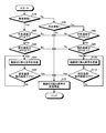
- FIG. 4 is a flow chart showing an example of the procedure of the air path switching operation during operation of the heat exchange ventilation system 100 according to the first embodiment of the present invention.
- step S10 the control unit 31 determines whether the current operation of the temperature control coil 21 is the heating operation.
- the control unit 31 detects the current outside air detected by the outside air temperature sensor 5 in step S20. It is determined whether or not the temperature of is less than 0.degree. In this case, 0 ° C. is a predetermined first temperature threshold.
- the control unit 31 determines the current temperature of the indoor air detected by the return air temperature sensor 6, ie, the indoor temperature in step S30. It is determined whether or not 10 ° C. or less. In this case, 10 ° C. is a predetermined second temperature threshold.
- step S30 If the current indoor temperature is 10 ° C. or lower, that is, if the answer is “Yes” in step S30, the control unit 31 transmits an air passage switching signal instructing switching of the air passage to the first air passage switching damper 22 in step S40. Then, the first switching control is performed to switch from the first air passage to the second air passage.
- the direction of the first air path switching damper 22 changes so as to switch from the first air path to the second air path only while the air path switching signal is being transmitted.
- step S50 the control unit 31 determines whether the temperature difference between the set temperature of the temperature adjustment coil 21 and the current temperature of the indoor air detected by the return air temperature sensor 6 is 3 ° C. or less. That is, it is determined whether or not (the set temperature of the temperature adjustment coil 21-the current indoor temperature ⁇ 3 ° C.).
- step S50 If the temperature difference between the set temperature of the temperature adjustment coil 21 and the current temperature of the indoor air detected by the return air temperature sensor 6 is not 3 ° C. or less, that is, if No in step S50, the process returns to step S40.
- step S70 If the temperature difference between the set temperature of the temperature adjustment coil 21 and the current temperature of the indoor air detected by the return air temperature sensor 6 is 3 ° C. or less, that is, in the case of Yes in step S50, control is performed in step S70.
- the unit 31 stops the transmission of the air passage switching signal, performs the second switching control, switches from the second air passage to the first air passage, and ends the series of air passage switching operations.
- control unit 31 stops the transmission of the air passage switching signal in step S70 and carries out the second switching control, and the first air passage is selected from the second air passage.
- the air path is switched to, and a series of air path switching operations are completed.
- the control unit 31 determines whether the current operation of the temperature adjustment coil 21 is the cooling operation in step S60. judge.
- the control unit 31 detects the current outside air detected by the outside air temperature sensor 5 in step S80. It is determined whether the temperature of is higher than 35.degree. In this case, 35 ° C. is a predetermined third temperature threshold.
- the control unit 31 determines the current temperature of the indoor air detected by the return air temperature sensor 6, ie, the indoor temperature in step S90. It is determined whether or not 30 ° C. or more. In this case, 30 ° C. is a predetermined fourth temperature threshold.
- step S90 the control unit 31 transmits an air passage switching signal to the first air passage switching damper 22 in step S100 to perform the first switching control. Implement and switch from the first air path to the second air path.
- step S110 the control unit 31 determines whether the temperature difference between the set temperature of the temperature adjustment coil 21 and the current temperature of the indoor air detected by the return air temperature sensor 6 is 3 ° C. or less. That is, it is determined whether or not (the set temperature of the temperature adjustment coil 21-the current indoor temperature ⁇ 3 ° C.).
- step S110 If the temperature difference between the set temperature of the temperature adjustment coil 21 and the current temperature of the indoor air detected by the return air temperature sensor 6 is not 3 ° C. or less, that is, if No in step S110, the process returns to step S100.
- step S70 If the temperature difference between the set temperature of the temperature adjustment coil 21 and the current temperature of the indoor air detected by the return air temperature sensor 6 is 3 ° C. or less, that is, in the case of Yes in step S110, control is performed in step S70.
- the unit 31 stops the transmission of the air passage switching signal, performs the second switching control, switches from the second air passage to the first air passage, and ends the series of air passage switching operations.
- control unit 31 stops the transmission of the air passage switching signal in step S70 and carries out the second switching control, and the first air passage from the second air passage.
- the air path is switched to, and a series of air path switching operations are completed.
- the temperature of the outside air and the return air temperature detected by the outside air temperature sensor 5 when the temperature control coil 21 operates in the heating operation mode or the cooling operation mode Control the first switching control of arranging the first air passage switching damper 22 at a position to switch from the air supply passage 11 to the return air passage when the temperature of the indoor air detected by the sensor 6 satisfies the predetermined temperature condition
- the part 31 carries out automatically. For this reason, from the supply air passage 11 that is an air passage that takes in the outside air, the indoor air is recirculated to an intermediate position on the upstream side of the temperature adjustment coil 21 in the supply air passage to circulate the room air.
- the air path can be automatically switched, and room air can be taken into the heat exchange ventilation system 100 instead of the outside air.
- the temperature of the air supplied to the room can be adjusted at a rapid temperature as compared with the case where the outside air is introduced into the heat exchange ventilation system 100, and the room temperature can be rapidly raised.
- the heat exchange type ventilation system 100 has both the outside air temperature and the room temperature low in, for example, the early morning of winter, and even when the temperature of the air passing through the heat exchange type ventilation device 1 is low, the heat exchange type ventilation system 100
- the temperature of the air supplied into the room can be rapidly warmed, and the temperature of the room can be rapidly raised, as compared with the case of being taken into the system.
- the heat exchange type ventilation system 100 realizes indoor air conditioning with only a device having both a ventilation function and a temperature control function. By using the heat exchange type ventilation system 100, a comfortable indoor environment can be realized even when reducing materials to be installed and duct piping and simplifying the air conditioning system to reduce the power consumption. Can.
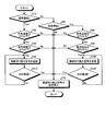
- FIG. 5 is a flowchart showing an example of the procedure of the air path switching operation during operation of the heat exchange ventilation system 100 according to the second embodiment of the present invention.
- the flowchart shown in FIG. 5 is different from the flowchart shown in FIG. 4 in that step S210 is performed instead of step S50 and step S220 is performed instead of step S110.
- step S210 the control unit 31 determines whether 30 minutes have elapsed since the execution of the first switching control in step S40, that is, whether 30 minutes have elapsed after the start of transmission of the air path switching signal.
- step S210 If 30 minutes have not elapsed after the execution of the first switching control, that is, if No in step S210, the process returns to step S40 to continue the first switching control. If 30 minutes have elapsed after the execution of the first switching control, that is, if the result of step S210 is YES, the process proceeds to step S70.
- step S220 the control unit 31 determines whether 30 minutes have elapsed since the execution of the first switching control in step S100, that is, whether 30 minutes have elapsed after the start of transmission of the air path switching signal.
- step S220 If 30 minutes have not elapsed since the execution of the first switching control, that is, if No in step S220, the process returns to step S100 to continue the first switching control. If 30 minutes have elapsed after execution of the first switching control, that is, if the result of step S220 is YES, the process proceeds to step S70.
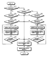
- FIG. 6 is a flow chart showing an example of the procedure of the air path switching operation during operation of the heat exchange ventilation system 100 according to Embodiment 3 of the present invention.
- the flowchart shown in FIG. 6 implements step S310 instead of steps S20 and S30, performs step S320 instead of step S50, performs step S330 instead of steps S80 and S90, and substitutes step S110. Is different from the flowchart shown in FIG. 4 in that step S340 is performed.
- step S310 the control unit 31 determines whether the current time has passed 6 am. If the current time has not passed 6 am, that is, if No in step S310, the process returns to step S310. In addition, when the current time has passed 6 am, that is, in the case of Yes in step S310, the process proceeds to step S40.
- step S320 the control unit 31 determines whether the current time has passed 8:00 am. If the current time has not passed 8:00 am, that is, if No in step S320, the process returns to step S40. In addition, when the current time has passed 8:00 am, that is, in the case of Yes in step S320, the process proceeds to step S70.
- step S330 the control unit 31 determines whether the current time has passed 6 am. If the current time has not passed 6 am, that is, if No in step S330, the process returns to step S330. When the current time passes 6 am, that is, in the case of Yes in step S330, the process proceeds to step S100.
- step S340 the control unit 31 determines whether the current time has passed 8:00 am. If the current time has not passed 8:00 am, that is, if No in step S340, the process returns to step S100. In addition, when the current time has passed 8:00 am, that is, in the case of Yes in step S340, the process proceeds to step S70.
- control unit 31 performs the first switching control when the current time is earlier than the predetermined time and the heat exchange ventilation system 100 is operating, and the current time is Implements the second switching control when the predetermined time has passed.
- the control unit 31 automatically performs the first switching control and the second switching control based on the current time to switch the air path. Also in this case, the same effect as that of the first embodiment can be obtained.
- Such control of the air path is suitable for use in places such as offices and schools where the heat exchange ventilation system 100 is used at a fixed time each day.
- the role of the heat exchange type ventilation system 100 is to the role of the ventilation system according to the user's request. It can be changed to the role of the interior machine.
- the above-mentioned control of the air path plays a dual role of the role of the ventilator and the role of the internal air conditioner in one heat exchange type ventilation system 100 especially when no other internal air conditioner is disposed in the room. Can be useful.
- FIG. 7 is a flow chart showing an example of the procedure of the air channel switching operation during operation of the heat exchange ventilation system 100 according to the fourth embodiment of the present invention.
- the flowchart shown in FIG. 7 differs from the flowchart shown in FIG. 4 in that steps S410, S420 and S430 are performed.
- step S410 after performing the first switching control in step S40, the control unit 31 performs control to increase the air volume of the air supply blower 3 compared with that before performing the first switching control to set the maximum notch.
- step S430 after performing the first switching control in step S100, the control unit 31 performs control to increase the air volume of the air supply blower 3 compared to that before performing the first switching control, and to set the maximum notch.
- step S420 the control unit 31 performs control to restore the air volume of the air supply blower 3 increased in steps S410 and S430 to the state before the first switching control.
- the air volume of the air supply blower 3 can be automatically increased after the execution of the first switching control than before the execution of the first switching control, and the temperature adjustment of the indoor air can be further enhanced. It can be done quickly.
- Embodiment 5 the control unit 31 controls the exhaust blower 4 to stop while the control unit 31 performs the second switching control after the execution of the first switching control after the first switching control, and the exhaust The control to reduce the air volume of the blower 4 for the first switching control than before performing the first switching control, and the case where the air volume of the exhaust blower 4 is switched to any control among the control for continuing the same state as before performing the first switching control explain.
- FIG. 8 is a flow chart showing an example of the procedure of the air path switching operation during operation of the heat exchange ventilation system 100 according to the fifth embodiment of the present invention. The flowchart shown in FIG. 8 differs from the flowchart shown in FIG. 4 in that steps S510, S520 and S530 are performed.
- control unit 31 performs control to stop the exhaust fan 4 according to the air amount instruction information transmitted from the remote controller 32 after execution of the first switching control in step S40, and the air amount of the exhaust fan 4
- the control to be reduced from before the first switching control and the air volume of the exhaust fan 4 are switched to any control among the controls for continuing the same state as before the first switching control.
- the control of the air volume of the exhaust fan 4 can be changed at any timing.
- step S520 the control unit 31 performs control to restore the air volume of the exhaust blower 4 changed in step S510 and step S520 to the state before the execution of the first switching control.
- the air volume of the exhaust blower 4 can be changed to any air volume after the first switching control is performed, and when reducing the air volume, the temperature adjustment of room air can be performed more rapidly It is possible.
- the control for stopping the exhaust blower and the air volume of the exhaust blower after the execution of the first switching control until the second switching control is performed.
- Any one of the control to be reduced compared to that before the switching control and the control for continuing the same state as that before the first switching control, which is determined in advance and set in the control unit 31 It is also possible to implement one control.
- the air volume of the exhaust blower 4 can be changed to any air volume after the first switching control is performed, and when reducing the air volume, it is possible to more rapidly adjust the temperature of the room air is there.
- FIG. 9 is a schematic view showing the structure of a heat exchange ventilation system 200 according to a sixth embodiment of the present invention in a simplified manner.
- the heat exchange type ventilation system 200 according to the sixth embodiment of the present invention is characterized in that the temperature control coil 25 is incorporated on the downstream side of the heat exchange element 2 inside the heat exchange type ventilation device 1. Different from 100.
- the control shown in the above-mentioned Embodiment 1 to Embodiment 5 is possible. An effect similar to that of the replacement ventilation system 100 can be obtained. Further, by incorporating the temperature control coil 25 into the heat exchange ventilator 1 in advance, the arrangement of the duct pipe that constitutes the downstream air supply air passage 11c becomes easy.
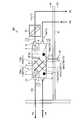
- FIG. 10 is a schematic view showing a configuration of a heat exchange ventilation system 300 according to a seventh embodiment of the present invention in a simplified manner.
- a second air passage switching damper 26 is provided at a part of the partition wall 8 instead of the first air passage switching damper 22.
- the second air passage switching damper 26 is an air passage, which is an air passage for taking in outside air, and an intermediate position on the upstream side of the temperature adjustment coil in the air passage. It is an air passage switching damper that switches between the return air supply air passage to be returned to the
- the partition wall 8 is formed with a bypass opening 8a communicating the region upstream of the air supply blower 3 in the air passage 11bb after the outside air heat exchange with the indoor air heat exchange air passage 12ba.
- a second air passage switching damper 26 which is an opening and closing part for opening and closing the bypass opening 8 a is disposed in the air passage 11 bb after the outside air heat exchange.
- the bypass opening 8a is for the purpose of flowing at least a part of the exhaust gas flowing through the indoor air heat exchange front air passage 12ba to the air passage 11bb after the outside air heat exchange. It is provided between the air passage 12ba.
- the room air heat exchange air passage 12ba and the outside air heat exchange after air passage 11bb are communicated via the bypass opening 8a, and the air heat exchange is also performed. It is possible to close the region adjacent to the heat exchange element 2 in the back air passage 11bb, that is, the space between the heat exchange element 2 and the air supply blower 3 in the air passage 11bb after heat exchange. As a result, the bypass flow of the exhaust flow passing from the indoor air heat exchange front air passage 12ba through the bypass opening 8a flows in the air passage 11bb after the outside air heat exchange. Then, the air flow upstream of the second air passage switching damper 26 in the air supply air passage 11 does not flow downstream of the second air passage switching damper 26.
- the second air passage switching damper 26 separates a portion on the downstream side of the heat exchange element in the air supply passage in the apparatus and a portion on the upstream side of the heat exchange element in the exhaust air passage in the heat exchange ventilator.
- the heat in the third air passage which is an air passage that takes in the outside air by opening the portion downstream of the heat exchange element in the air supply air passage in the heat exchange type ventilation device, and the air supply air passage in the heat exchange type ventilation device
- the upstream side of the exchange element and the downstream side of the heat exchange element in the air supply path in the heat exchange ventilator and the upstream side of the heat exchange element in the exhaust air path in the heat exchange ventilator And an air passage switching damper disposed on the downstream side of the heat exchange element in the air supply passage in the heat exchange type ventilation device, which switches between the air passage and the fourth air passage which circulates the room air.
- the second air passage is a return air supply air passage.
- the heat exchange type ventilation system 300 including the second air path switching damper 26 instead of the first air path switching damper 22 can obtain the same effect as the heat exchange type ventilation system 100.
- the techniques described in the first to sixth embodiments described above can also be applied to the heat exchange type ventilation system 300.
- the bypass flow does not pass through the heat exchange element 2, but since the bypass flow is not the outside air but the room air, the outside air is taken into the heat exchange type ventilation system 300.
- the temperature of the air supplied into the room can be rapidly warmed, and the temperature in the room can be rapidly raised.
- Reference Signs List 1 heat exchange type ventilation device, 1a outside air suction port, 1b air supply discharge port, 1c indoor air suction port, 1d exhaust discharge port, 1e housing, 2 heat exchange element, 3 air supply blower, 4 exhaust air blower, 5 Outside air temperature sensor, 6 return air temperature sensor, 7, 8 partition wall, 8a bypass opening, 11 air supply air path, 11a upstream air supply air path, 11b air supply air path in the device, 11ba outside air heat exchange front air path, 11bb outside air heat After replacement air passage, 11bc heat exchange element air supply air passage, 11c downstream air supply air passage, 12 exhaust air passage, 12a upstream air exhaust passage, 12b exhaust air passage in the device, 12ba indoor air heat exchange front air passage, 12bb indoor Air heat exchange air passage, 12bc heat exchange element exhaust air passage, 12c downstream side exhaust air passage, 13 branch air supply air passage, 21, 25 temperature control coil, 22 first air passage cut off Damper, 23 motor controller, 24 motor, 26 second air path switching damper, 31 controller, 32 remote controller,
Abstract
A heat exchanging type ventilation system (100) comprises: a heat exchanging type ventilation device (1); a temperature regulating coil (21) that is disposed downstream of a heat exchanging element (2) in an air supply channel (11) and that heats or cools air passing through the air supply channel (11) further downstream than the heat exchanging element (2); a return air supply flow channel that causes indoor air to return to an intermediate position upstream of the temperature regulating coil (21) in the air supply channel (11); a channel switching damper that switches between the return air supply flow channel and the air supply channel (11) serving as a channel taking in outdoor air; an outdoor air temperature sensor (5) that detects the temperature of the outdoor air; a return air temperature sensor (6) that detects the temperature of indoor air exhausted to the outdoors; and a control unit (31) that controls the operation of the heat exchanging type ventilation device (1), the temperature regulating coil (21), and the channel switching damper.
Description
本発明は、室内の空気を室外へ排出する排気流と、室外の空気を室内へ給気する給気流との間で熱交換を行う熱交換型換気装置を有する熱交換型換気システムに関するものである。
The present invention relates to a heat exchange ventilation system having a heat exchange ventilator that exchanges heat between an exhaust gas flow for discharging indoor air to the outside of the room and a charge air flow for supplying air to the room outside. is there.
熱交換型換気装置には、室内からの排気流と室外からの給気流とを全熱交換素子で交差させることによって排気流と給気流との間で温度および湿度の交換を行った後に、さらに給気風路に設置された温度調整機器によって給気流の温度を調整する機器が存在する。このような機器には、温度調整コイルを有する別の機器を熱交換型換気装置の給気ダクト上に設置する分離型と、熱交換型換気装置の内部に温度調整コイルを有する一体型のものとが存在する。
In the heat exchange type ventilator, after exchanging the temperature and humidity between the exhaust flow and the charge flow by causing the exhaust flow from the room and the charge flow from the outside to cross at the total heat exchange element, There is a device for adjusting the temperature of the charge air flow by means of a temperature control device installed in the charge air path. Such devices include a separate type in which another device having a temperature control coil is installed on the air supply duct of the heat exchange ventilator, and an integrated type having a temperature control coil inside the heat exchange ventilator. And exist.
特許文献1には、ケーシングの内部における室外供給口から室内供給口に至る室外空気供給通路の途中に空調コイルを備えた全熱交換換気装置が開示されている。
Patent Document 1 discloses a total heat exchange ventilator having an air conditioning coil in the middle of an outdoor air supply passage extending from an outdoor supply port to an indoor supply port inside a casing.
しかしながら、温度調整コイルを有した熱交換型換気装置において、例えば冬季の早朝に換気および暖房を行う際、屋外の気温および室内の気温がともに低い場合、全熱交換素子によって外気と室内還気間で温度交換を行ったとしても、全熱交換素子の通過後の給気流の温度が低いことに起因して、温度調整コイルで温調しても室内への給気風が十分な温度まで上がらない状態が継続して、暖房するために時間がかかる可能性、または室内が暖房されない状態になってしまう可能性がある。
However, in a heat exchange type ventilator having a temperature control coil, for example, when ventilating and heating in the early morning of winter, when both the outdoor air temperature and the indoor air temperature are low, the total heat exchange element is between the outside air and the indoor return air. Even if the temperature is exchanged, the temperature of the air flow after the passage of all the heat exchange elements is low, so even if the temperature is adjusted by the temperature control coil, the air supplied into the room does not rise to a sufficient temperature. The condition may continue to take time to heat up, or the room may be left unheated.
同様に夏季において、室内の温度と外気との温度差が小さいために温度調整コイルを通過後の給気流の温度が低くならず、室内温度を目標温度まで冷房するために時間がかかる可能性、または室内が冷房されない状態になってしまう可能性がある。
Similarly, in summer, since the temperature difference between the room temperature and the outside air is small, the temperature of the charge air flow after passing through the temperature adjustment coil may not decrease, and it may take time to cool the room temperature to the target temperature. Or, the room may not be cooled.
また、早朝などにおける熱交換型換気装置の運転では、在室する人数がさほど多くないことが予想されることから、新鮮な外気取り入れのニーズが高くないと考えられる。このような状況で、例えば冬季の場合、室内がまだ暖められていないにもかかわらず、温度の低い外気を換気によって取り入れることは、空気調和の効率が低いという問題がある。
In addition, in the operation of the heat exchange type ventilation device in the early morning and the like, it is expected that the number of people in the room is not so large, and therefore the need for fresh fresh air intake is not high. In such a situation, for example, in winter, even if the room has not been warmed, it is a problem that the outside air with low temperature is taken in by ventilation, the efficiency of air conditioning is low.
上記の問題は、特に、換気と空気調和とを、熱交換型換気装置と、温度調整コイルとからなるシステムによって単独で行う場合、すなわち温度調整機能を備えた熱交換型換気装置の他に何も内調機を設置しない場合に顕著に生じることになる。
The above-mentioned problems are particularly encountered when performing ventilation and air conditioning independently by a system consisting of a heat exchange ventilator and a temperature control coil, ie, anything other than a heat exchange ventilator with a temperature control function. It will be noticeable if you do not install the internal air conditioner.
本発明は、上記に鑑みてなされたものであって、熱交換型換気装置と温度調整コイルとを備え、室内に給気する空気を効率的に温度調整することができる熱交換型換気システムを得ることを目的とする。
The present invention has been made in view of the above, and includes a heat exchange ventilator and a temperature control coil, and a heat exchange ventilator system capable of efficiently adjusting the temperature of air supplied into a room. The purpose is to get.
上述した課題を解決し、目的を達成するために、本発明にかかる熱交換型換気システムは、熱交換型換気装置と、室外の外気を室内に給気する給気風路と、室内の空気を室外に排気する排気風路とを備えた熱交換型換気システムである。熱交換型換気システムは、熱交換型換気装置内の給気風路である装置内給気風路と、熱交換型換気装置内の排気風路である装置内排気風路と、が独立して内部に形成された筐体と、装置内給気風路に設けられた給気用送風機と、装置内排気風路に設けられた排気用送風機と、筐体の内部に設けられて装置内給気風路を通過する空気と装置内排気風路を通過する空気との間で熱交換させる熱交換素子と、を備えた熱交換型換気装置を備える。熱交換型換気システムは、給気風路における熱交換素子よりも下流側に配置されて、熱交換素子よりも下流側の給気風路を通過する空気を加熱または冷却する温度調整コイルと、室内の空気を給気風路における温度調整コイルよりも上流側の途中位置に還流させる還流給気風路と、外気を取り入れる風路である給気風路と還流給気風路とを切り換える風路切り換えダンパーと、外気の温度を検知する外気温度センサーと、室外に排気する室内の空気の温度を検知する還気温度センサーと、熱交換型換気装置と温度調整コイルと風路切り換えダンパーの動作を制御する制御部と、を備える。
In order to solve the problems described above and achieve the object, a heat exchange type ventilation system according to the present invention comprises a heat exchange type ventilation device, a supply air flow path for supplying outside air to the room, and room air. It is a heat exchange type ventilation system provided with an exhaust air path which exhausts to the outdoors. In the heat exchange type ventilation system, the air supply path in the apparatus, which is the air supply path in the heat exchange type ventilator, and the exhaust air path, which is the exhaust air path in the heat exchange type ventilator, are independent of each other , An air supply fan provided in the apparatus air supply air path, an exhaust air fan provided in the apparatus air exhaust air path, and an apparatus air supply air path provided inside the case A heat exchange element including a heat exchange element for exchanging heat between the air passing through and the air passing through the in-apparatus exhaust air passage. The heat exchange type ventilation system is disposed downstream of the heat exchange element in the air supply air path, and is provided with a temperature control coil for heating or cooling air passing through the air supply air path downstream of the heat exchange element; An air passage switching damper for returning air to an intermediate position on the upstream side of the temperature adjustment coil in the air supply air passage, an air passage switching damper for switching between the air supply air passage which is an air passage taking in the outside air and the reflux air supply passage; Air temperature sensor for detecting the temperature of the air, return air temperature sensor for detecting the temperature of the air in the room exhausted to the outside, a control unit for controlling the operation of the heat exchange ventilator, the temperature control coil and the air path switching damper And.
本発明にかかる熱交換型換気システムは、熱交換型換気装置と温度調整コイルとを備え、室内に給気する空気を効率的に温度調整することができる、という効果を奏する。
The heat exchange type ventilation system according to the present invention has a heat exchange type ventilation device and a temperature control coil, and has an effect that the temperature of air supplied into the room can be efficiently adjusted.
以下に、本発明の実施の形態にかかる熱交換型換気システムを図面に基づいて詳細に説明する。なお、この実施の形態によりこの発明が限定されるものではない。
Hereinafter, a heat exchange type ventilation system according to an embodiment of the present invention will be described in detail based on the drawings. The present invention is not limited by the embodiment.
実施の形態1.
図1は、本発明の実施の形態1にかかる熱交換型換気システム100の構成を簡略化して示す模式図である。図2は、本発明の実施の形態1にかかる熱交換型換気システム100の制御に関わる機能構成を示す図である。Embodiment 1
FIG. 1: is a schematic diagram which simplifies and shows the structure of the heat exchangesystem ventilation system 100 concerning Embodiment 1 of this invention. FIG. 2 is a diagram showing a functional configuration related to control of the heat exchange ventilation system 100 according to the first embodiment of the present invention.
図1は、本発明の実施の形態1にかかる熱交換型換気システム100の構成を簡略化して示す模式図である。図2は、本発明の実施の形態1にかかる熱交換型換気システム100の制御に関わる機能構成を示す図である。
FIG. 1: is a schematic diagram which simplifies and shows the structure of the heat exchange
熱交換型換気システム100は、室外の空気である外気を室内に給気する給気風路11と、室内の空気を室外に排気する排気風路12と、を備えた熱交換型換気システムである。熱交換型換気システム100は、外気を取り込む外気吸込口1a、外気を室内に給気する給気吐出口1b、室内空気を取り込む室内空気吸込口1cおよび室内空気を屋外へ排気する排気吐出口1dを備えた筐体1eの内部に全熱交換器である熱交換素子2が配置された熱交換型換気装置1を有している。熱交換型換気装置1は、筐体1eの内部に熱交換素子2を有する空調用の熱交換型換気装置である。熱交換型換気装置1は、天井裏52に隠蔽された状態で設置されている。また、熱交換型換気装置1は、筐体1eの外部に取り付けられた制御部31と、室内53に設置されたリモートコントローラー32とを備える。図1においては、天井51の上の領域が天井裏52であり、天井51の下の領域が室内53である。
The heat exchange type ventilation system 100 is a heat exchange type ventilation system provided with an air supply path 11 for supplying outside air which is outdoor air to the room and an exhaust air path 12 for exhausting indoor air to the outside. . The heat exchange type ventilation system 100 includes an outside air inlet 1a for taking in outside air, an air supply outlet 1b for supplying outside air to the room, an indoor air inlet 1c for taking in room air, and an exhaust outlet 1d for discharging the room air to the outside. The heat exchange type ventilation device 1 is provided with the heat exchange element 2 which is a total heat exchanger disposed in the inside of a housing 1e having the above. The heat exchange type ventilation device 1 is a heat exchange type ventilation device for air conditioning which has a heat exchange element 2 in the inside of a housing 1 e. The heat exchange type ventilator 1 is installed in a state of being concealed by the ceiling 52. In addition, the heat exchange type ventilation device 1 includes a control unit 31 attached to the outside of the housing 1 e and a remote controller 32 installed in the room 53. In FIG. 1, the area above the ceiling 51 is the ceiling 52, and the area below the ceiling 51 is the room 53.
なお、図1において、符号OAは外気(Outdoor Air)、符号SAは給気(Supply Air)、符号RAは還気(Return Air)、符号EAは排気(Exhaust Air)を示している。
Note that in FIG. 1, the symbol OA indicates the outdoor air, the symbol SA indicates the supply air, the symbol RA indicates the return air, and the symbol EA indicates the exhaust air.
熱交換型換気システム100の給気風路11は、熱交換型換気装置1よりも上流側であって室外に連通する上流側給気風路11aと、熱交換型換気装置1内の給気風路11である装置内給気風路11bと、熱交換型換気装置1よりも下流側であって室内に連通する下流側給気風路11cと、の3つに分けられる。
The air supply path 11 of the heat exchange type ventilation system 100 is an upstream side air supply path 11a which is upstream of the heat exchange type ventilation device 1 and is communicated with the outside, and the air supply path 11 in the heat exchange type ventilation system 1. It is divided into three, i.e., the in-apparatus supply air passage 11b and the downstream side supply air passage 11c which is downstream of the heat exchange ventilator 1 and which communicates with the room.
また、熱交換型換気システム100の排気風路12は、熱交換型換気装置1よりも上流側であって室内に連通する上流側排気風路12aと、熱交換型換気装置1内の排気風路12である装置内排気風路12bと、熱交換型換気装置1よりも下流側であって室外に連通する下流側排気風路12cと、の3つに分けられる。
Further, the exhaust air passage 12 of the heat exchange type ventilation system 100 is an upstream side of the heat exchange type ventilator 1 and is in communication with the indoor side, and the exhaust air in the heat exchange type ventilator 1 It is divided into three: an in-apparatus exhaust air passage 12b, which is a passage 12, and a downstream-side exhaust air passage 12c which is downstream of the heat exchange ventilator 1 and which communicates with the outside.
熱交換型換気装置1は、熱交換素子2を介して外気吸込口1aと給気吐出口1bとを結ぶ熱交換型換気装置1内の給気風路11である装置内給気風路11bと、熱交換素子2を介して室内空気吸込口1cと排気吐出口1dを結ぶ熱交換型換気装置1内の排気風路12である装置内排気風路12bと、を備える。装置内給気風路11bと装置内排気風路12bとは、互いに独立した風路となっている。
The heat exchange ventilator 1 includes an in-apparatus air supply passage 11b which is an air supply airflow passage 11 in the heat exchange ventilator 1 connected between the outside air suction port 1a and the air supply outlet 1b via the heat exchange element 2; And an in-apparatus exhaust air passage 12b which is an exhaust air passage 12 in the heat exchange ventilator 1 connecting the indoor air suction port 1c and the exhaust discharge port 1d via the heat exchange element 2. The in-device supply air passage 11b and the in-device exhaust air passage 12b are air passages independent of each other.
装置内給気風路11bは、外気OAを室内へ給気するための風路であり、外気吸込口1aと熱交換素子2との間に形成された外気熱交換前風路11baと、熱交換素子2と給気吐出口1bとの間に形成された外気熱交換後風路11bbと、熱交換素子2の内部に形成された熱交換素子給気風路11bcと、を有している。
The in-apparatus supply air path 11b is an air path for supplying the outside air OA into the room, and heat exchange with the outside air heat exchange front air path 11ba formed between the outside air suction port 1a and the heat exchange element 2 It has an air passage 11bb after external heat exchange formed between the element 2 and the air supply / discharge port 1b, and a heat exchange element air supply passage 11bc formed inside the heat exchange element 2.
装置内排気風路12bは、室内空気である還気RAを室外へ排気するための風路であり、室内空気吸込口1cと熱交換素子2との間に形成された室内空気熱交換前風路12baと、熱交換素子2と排気吐出口1dとの間に形成された室内空気熱交換後風路12bbと、熱交換素子2の内部に形成された熱交換素子排気風路12bcと、を有している。この構成により、装置内給気風路11bと装置内排気風路12bとは、熱交換素子2において交差している。
The in-apparatus exhaust air path 12b is an air path for exhausting the return air RA, which is room air, to the outside, and the room air heat exchange front wind formed between the room air suction port 1c and the heat exchange element 2 A passage 12ba, an indoor air heat exchange air passage 12bb formed between the heat exchange element 2 and the exhaust outlet 1d, and a heat exchange element exhaust air passage 12bc formed inside the heat exchange element 2; Have. With this configuration, the in-apparatus supply air passage 11 b and the in-apparatus exhaust air passage 12 b intersect at the heat exchange element 2.
外気熱交換後風路11bbと室内空気熱交換後風路12bbとは、熱交換素子2により仕切られている。外気熱交換前風路11baと室内空気熱交換前風路12baとは、熱交換素子2により仕切られている。外気熱交換前風路11baと室内空気熱交換後風路12bbとは、平板状の仕切壁7により区画されている。そして、室内空気熱交換前風路12baと外気熱交換後風路11bbとは、仕切壁8により仕切られている。
The air passage 11 bb after the outside air heat exchange and the air passage 12 bb after the indoor air heat exchange are partitioned by the heat exchange element 2. The outdoor air heat exchange front air passage 11 ba and the indoor air heat exchange front air passage 12 ba are separated by the heat exchange element 2. The outdoor air heat exchange front air passage 11 ba and the indoor air heat exchange after air passage 12 bb are partitioned by a flat partition wall 7. The indoor air heat exchange front air passage 12 ba and the outdoor air heat exchange after air passage 11 bb are partitioned by the partition wall 8.
熱交換型換気装置1は、外気吸込口1aから給気吐出口1bへ向かう給気流の流れを生成する給気用送風機3を装置内給気風路11bに備える。また、熱交換型換気装置1は、室内空気吸込口1cから排気吐出口1dへ向かう排気流の流れを生成する排気用送風機4を装置内排気風路12bに備える。
The heat exchange type ventilation device 1 includes an air supply blower 3 for generating a flow of the air supply flow from the outside air suction port 1a toward the air supply discharge port 1b in the apparatus air supply air passage 11b. Further, the heat exchange type ventilation device 1 is provided with the exhaust blower 4 for generating the flow of the exhaust flow from the indoor air suction port 1c to the exhaust discharge port 1d in the in-device exhaust air passage 12b.
給気用送風機3は、外気熱交換後風路11bb内に配置され、給気用送風機3を駆動するための不図示の給気用モーターを内部に備えている。排気用送風機4は、室内空気熱交換後風路12bb内に配置され、排気用送風機4を駆動するための不図示の排気用モーターを内部に備えている。給気用モーターと排気用モーターとは、後述する制御部31による制御に応じて回転速度が変化する。
The air supply blower 3 is disposed in the air passage 11bb after the outside air heat exchange, and internally includes an air supply motor (not shown) for driving the air supply blower 3. The exhaust blower 4 is disposed in the air passage 12bb after the indoor air heat exchange, and includes an exhaust motor (not shown) for driving the exhaust blower 4 therein. The rotational speeds of the air supply motor and the exhaust motor change in accordance with control by the control unit 31 described later.
外気吸込口1aには、ダクト配管によって構成され、外気OAを取り入れて熱交換型換気装置1に流すための外気取り入れ風路である上流側給気風路11aが接続されている。給気吐出口1bには、ダクト配管によって構成され、熱交換型換気装置1から給気流を室内に流すための給気吐出風路である下流側給気風路11cが接続されている。室内空気吸込口1cには、ダクト配管によって構成され、室内空気を取り入れて熱交換型換気装置1に流すための室内空気吸込風路である上流側排気風路12aが接続されている。排気吐出口1dには、ダクト配管によって構成され、熱交換型換気装置1から排気流を屋外に流すための排気吐出風路である下流側排気風路12cが接続されている。
Connected to the outside air suction port 1a is an upstream air supply air passage 11a which is constituted by a duct pipe and is an outside air intake air passage for taking in outside air OA and flowing it to the heat exchange type ventilator 1. A downstream side air supply air passage 11c, which is a supply air discharge air passage for flowing the air supply flow from the heat exchange type ventilation device 1 into the room, is connected to the air supply discharge port 1b. Connected to the indoor air suction port 1 c is an upstream side exhaust air passage 12 a which is an indoor air suction air passage which is constituted by a duct pipe and takes in the indoor air and flows it to the heat exchange ventilator 1. The exhaust gas discharge port 1d is connected to a downstream side exhaust air flow path 12c which is an exhaust gas discharge air path which is constituted by a duct pipe and allows the exhaust gas flow from the heat exchange ventilator 1 to flow to the outside.
下流側給気風路11cには、熱交換型換気装置1の外部に設けられた温度調整コイル21が配置されている。温度調整コイル21は、下流側給気風路11cを通過する給気流を加熱または冷却することが可能な熱交換器である。すなわち、温度調整コイル21は、給気風路における熱交換素子2よりも下流側に配置されて、熱交換素子2よりも下流側の給気風路を通過する空気を加熱または冷却する。温度調整コイル21は、制御部31によって熱交換型換気装置1と連動して運転が制御され、ユーザーが設定した目標温度に室内温度が到達するように、下流側給気風路11cを通過する給気流の温度を温度調整する。すなわち、温度調整コイル21は、熱交換型換気装置1から供給された給気空気が温度調整コイル21を通過するときに、通過する給気空気を加熱する。また、温度調整コイル21は、熱交換型換気装置1から供給された給気空気が温度調整コイル21を通過するときに、通過する給気空気を冷却する。
A temperature control coil 21 provided outside the heat exchange ventilator 1 is disposed in the downstream air supply passage 11c. The temperature control coil 21 is a heat exchanger capable of heating or cooling the air supply flow passing through the downstream air supply air passage 11c. That is, the temperature control coil 21 is disposed downstream of the heat exchange element 2 in the air supply passage, and heats or cools the air passing through the air supply passage downstream of the heat exchange element 2. The operation of the temperature control coil 21 is controlled by the control unit 31 in conjunction with the heat exchange ventilator 1, and the air supply passes through the downstream air supply air passage 11 c so that the room temperature reaches the target temperature set by the user. Adjust the temperature of the air flow. That is, when the supplied air supplied from the heat exchange ventilator 1 passes through the temperature control coil 21, the temperature control coil 21 heats the supplied supply air. In addition, the temperature control coil 21 cools the passing air, when the supplied air supplied from the heat exchange ventilator 1 passes through the temperature control coil 21.
上述するように、図1において、符号OAは外気、符号SAは給気、符号RAは還気、符号EAは排気を示している。
As described above, in FIG. 1, the symbol OA indicates outside air, the symbol SA indicates air supply, the symbol RA indicates return air, and the symbol EA indicates exhaust.
外気OAは、室外から、建物の外部に連通した上流側給気風路11aを介して、外気吸込口1aから外気熱交換前風路11baへ流入して給気流となる。外気熱交換前風路11baへ流入した給気流は、熱交換素子2、外気熱交換後風路11bb、給気用送風機3、給気吐出口1b、下流側給気風路11c、温度調整コイル21および下流側給気風路11cを経て室内へ吹き出される。
The outside air OA flows from the outside air suction port 1a into the outside air heat exchange front air passage 11ba from the outside via the upstream air supply air passage 11a communicated with the outside of the building from the outside, and becomes an air supply flow. The air flow flowing into the outside air heat exchange front air path 11ba is the heat exchange element 2, the air path 11bb after the outside air heat exchange, the air blower 3 for air supply, the air supply outlet 1b, the downstream air supply air path 11c, and the temperature control coil 21. And, it is blown out into the room through the downstream air supply path 11c.
還気RAは、室内から、室内に連通した上流側排気風路12aを介して、室内空気吸込口1cから室内空気熱交換前風路12baへ流入して排気流となる。室内空気熱交換前風路12baへ流入した排気流は、熱交換素子2、室内空気熱交換後風路12bb、排気用送風機4および下流側排気風路12cを経て排気EAとして、室外へ吹き出される。
The return air RA flows from the indoor air suction port 1c into the indoor air heat exchange front air passage 12ba from the room via the upstream side exhaust air passage 12a communicating with the room and becomes an exhaust flow. The exhaust gas flowed into the indoor air heat exchange front air passage 12ba is blown out to the outside as the exhaust air EA through the heat exchange element 2, the air passage 12bb after the indoor air heat exchange, the exhaust blower 4 and the downstream side exhaust air passage 12c. Ru.
室内空気熱交換前風路12baには、室内空気熱交換前風路12baを通過する空気の温度、すなわち外気の温度を検知する外気温度センサー5が配置されている。外気温度センサー5は、熱交換型換気装置1の電源がオン状態の間、予め設定された既定の周期で外気の温度を検出し、検出した外気の温度の情報を後述する制御部31に送信する。
An outdoor air temperature sensor 5 for detecting the temperature of air passing through the indoor air heat exchange front air passage 12ba, that is, the temperature of the outside air, is disposed in the indoor air heat exchange front air passage 12ba. The outside air temperature sensor 5 detects the temperature of outside air at a preset predetermined cycle while the heat exchange type ventilator 1 is turned on, and transmits information on the detected outside air temperature to the control unit 31 described later Do.
また、室内空気熱交換前風路12baには、室内空気熱交換前風路12baを通過する空気の温度、すなわち室内空気である還気の温度を検知することで室内温度を検知する還気温度センサー6が配置されている。還気温度センサー6は、熱交換型換気装置1の電源がオン状態の間、予め設定された周期で室内空気の温度を検出し、検出した室内空気の温度の情報を後述する制御部31に送信する。
In addition, the temperature of the air passing through the room air heat exchange front air path 12ba, that is, the temperature of the return air which is the room air, is detected in the room air heat exchange front air path 12ba. A sensor 6 is arranged. The return air temperature sensor 6 detects the temperature of the room air at a preset cycle while the power of the heat exchange ventilator 1 is in the on state, and sends the detected information of the temperature of the room air to the control unit 31 described later. Send.
また、外気取り入れ風路を構成する上流側給気風路11aの途中には、ダクト配管によって構成され、上流側給気風路11aと室内とを連通させる分岐給気風路13が接続されている。すなわち、上流側給気風路11aには、給気風路11における熱交換型換気装置1よりも上流側の上流側給気風路11aの途中位置から分岐されて、上流側給気風路11aと室内とを連通させる分岐給気風路13が接続されている。
Further, a branch air supply passage 13 which is constituted by a duct pipe and connects the upstream side air supply passage 11a with the room is connected midway of the upstream side air supply passage 11a constituting the outside air intake air passage. That is, the upstream air supply air passage 11a is branched from the midway position of the upstream air supply air passage 11a on the upstream side of the heat exchange ventilator 1 in the air supply air passage 11, and the upstream air supply air passage 11a and the room The branch air supply path 13 which connects the two is connected.
そして、熱交換型換気システム100は、外気を取り入れる風路である給気風路11と、室内の空気を給気風路における温度調整コイル21よりも上流側の途中位置に還流して室内空気を循環させる風路である還流給気風路と、を切り換える風路切り換えダンパーが設けられている。すなわち、上流側給気風路11aの途中には、給気風路における熱交換型換気装置1よりも上流側の上流側給気風路11aの途中位置に配置されて、分岐給気風路13を塞ぐとともに上流側給気風路11aを開放して外気を取り入れる風路である第1風路と、上流側給気風路11aの上流側を塞ぐとともに上流側給気風路11aの分岐給気風路13よりも下流側の部分と分岐給気風路13とを連通させて室内空気を循環させる風路である第2風路と、を切り換える風路切り換えダンパーである第1風路切り換えダンパー22が設けられている。そして、第2風路が還流給気風路である。
Then, the heat exchange type ventilation system 100 circulates the room air by recirculating the air in the room to the midway position on the upstream side of the temperature control coil 21 in the air supply path, and the air supply path 11 which is an air path for taking in outside air. An air passage switching damper is provided to switch between the return air passage, which is an air passage to be driven. That is, in the middle of the upstream air supply air passage 11a, it is disposed at an intermediate position of the upstream air supply air passage 11a on the upstream side of the heat exchange ventilator 1 in the air supply air passage and blocks the branch air supply air passage 13. The first air passage, which is an air passage that opens the upstream air supply air passage 11a and takes in the outside air, and the upstream air supply passage 11a, blocks the upstream side of the upstream air supply air passage 11a and the downstream air supply passage 13 of the upstream air supply air passage 11a. A first air passage switching damper 22 is provided, which is an air passage switching damper for switching between a second air passage which is an air passage for circulating indoor air by communicating the side portion with the branch air supply air passage 13. The second air passage is a return air supply air passage.
第1風路切り換えダンパー22は、例えば上流側給気風路11aの内部で回転する板からなり、制御部31の制御によってモーター制御部23がモーター24を駆動させることによって上流側給気風路11a内での向きが変化して、第1風路と第2風路とを切り換えることができる。
The first air passage switching damper 22 is formed of, for example, a plate rotating inside the upstream air supply air passage 11a, and the motor control unit 23 drives the motor 24 under the control of the control unit 31 to inside the upstream air supply air passage 11a. The direction of the air flow changes, and the first air passage and the second air passage can be switched.
制御部31は、熱交換型換気装置1と温度調整コイル21と風路切り換えダンパーの動作を制御する動作制御部としての機能と、風路切り換え信号の送信および熱交換型換気システム100内の他の構成部との情報通信を行う通信部としての機能を有する。制御部31は、リモートコントローラー32で受け付けられてリモートコントローラー32から送信された熱交換型換気装置1の動作を指示する情報に基づいて、または制御部31にあらかじめ設定されている動作を指示する情報に基づいて、熱交換型換気装置1の動作を制御する。制御部31は、リモートコントローラー32で受け付けられてリモートコントローラー32から送信された温度調整コイル21の動作を指示する情報に基づいて、または制御部31にあらかじめ設定されている動作を指示する情報に基づいて、温度調整コイル21の動作を制御する。また、制御部31は、リモートコントローラー32で受け付けられてリモートコントローラー32から送信されて第1風路切り換えダンパー22の動作を指示する情報に基づいて、または制御部31にあらかじめ設定されている動作を指示する情報に基づいて、第1風路切り換えダンパー22の動作を制御する。
The control unit 31 has a function as an operation control unit that controls the operation of the heat exchange ventilator 1, the temperature control coil 21, and the air passage switching damper, transmission of an air passage switching signal, and others in the heat exchange ventilation system 100. Has a function as a communication unit that performs information communication with the component units of The control unit 31 instructs the control unit 31 to perform an operation set in advance based on the information instructing the operation of the heat exchange ventilator 1 received by the remote controller 32 and transmitted from the remote controller 32. The operation of the heat exchange ventilator 1 is controlled based on The control unit 31 is based on the information instructing the operation of the temperature adjustment coil 21 received by the remote controller 32 and transmitted from the remote controller 32, or based on the information instructing the control unit 31 to perform an operation set in advance. Thus, the operation of the temperature control coil 21 is controlled. In addition, the control unit 31 receives an operation received from the remote controller 32 and transmitted from the remote controller 32 to instruct an operation of the first air passage switching damper 22 or an operation preset in the control unit 31. The operation of the first air path switching damper 22 is controlled based on the instructed information.
制御部31は、温度調整コイル21が、空気を加熱する暖房運転モードまたは空気を冷却する冷房運転モードで運転する際に、外気温度センサー5によって検知された外気の温度および還気温度センサー6によって検知された室内の空気の温度が既定の温度条件を満たす場合に、給気風路11から還流給気風路に切り換える位置に第1風路切り換えダンパー22を配置する第1切り換え制御を実施する。
The control unit 31 controls the temperature control coil 21 by the temperature of the outside air detected by the outside air temperature sensor 5 and the return air temperature sensor 6 when operating in the heating operation mode for heating the air or the cooling operation mode for cooling the air. The first switching control is performed in which the first air passage switching damper 22 is disposed at a position where the air supply passage 11 is switched to the return air supply passage when the detected temperature of the indoor air satisfies the predetermined temperature condition.
具体的に、本実施の形態1では、第1切り換え制御を実施することによって第1風路切り換えダンパー22の向きが、分岐給気風路13を塞ぐとともに上流側給気風路11aを開放する位置から、上流側給気風路11aの上流側を塞ぐとともに上流側給気風路11aの分岐給気風路13よりも下流側の部分と分岐給気風路13とを連通させる位置に変化する。これにより、第1風路から第2風路に風路が切り換えられる。
Specifically, in the first embodiment, by performing the first switching control, the direction of the first air passage switching damper 22 closes the branch air supply air passage 13 and from the position where the upstream air supply air passage 11a is opened. The upstream supply air path 11a is closed at the same time as closing the upstream side of the upstream supply air path 11a and making the branch air supply path 13 communicate with a portion on the downstream side of the branch air supply path 13. Thus, the air passage is switched from the first air passage to the second air passage.
すなわち、制御部31は、温度調整コイル21が暖房運転モードで運転しており、外気温度センサー5によって検知された外気の温度が既定の第1温度閾値以下であり、還気温度センサー6によって検知された室内の空気の温度が既定の第2温度閾値以下である場合に、第1切り換え制御を実施する。既定の第1温度閾値は、温度調整コイル21が暖房運転モードで運転している場合に、制御部31が第1切り換え制御を実施するか否かを判定するための外気温度センサー5の温度閾値である。既定の第2温度閾値は、温度調整コイル21が暖房運転モードで運転している場合に、制御部31が第1切り換え制御を実施するか否かを判定するための還気温度センサー6の温度閾値である。
That is, in the control unit 31, the temperature control coil 21 operates in the heating operation mode, the temperature of the outside air detected by the outside air temperature sensor 5 is equal to or lower than the predetermined first temperature threshold, and is detected by the return air temperature sensor 6. The first switching control is performed when the temperature of the indoor air being stored is less than or equal to the predetermined second temperature threshold. The predetermined first temperature threshold is the temperature threshold of the outside air temperature sensor 5 for determining whether the control unit 31 performs the first switching control when the temperature adjustment coil 21 is operating in the heating operation mode. It is. The predetermined second temperature threshold is the temperature of the return air temperature sensor 6 for determining whether or not the control unit 31 performs the first switching control when the temperature adjustment coil 21 is operated in the heating operation mode. It is a threshold.
また、制御部31は、温度調整コイル21が冷房運転モードで運転しており、外気温度センサー5によって検知された外気の温度が既定の第3温度閾値以上であり、還気温度センサー6によって検知された室内の空気の温度が既定の第4温度閾値以上である場合に、第1切り換え制御を実施する。既定の第3温度閾値は、温度調整コイル21が冷房運転モードで運転している場合に、制御部31が第1切り換え制御を実施するか否かを判定するための外気温度センサー5の温度閾値である。既定の第4温度閾値は、温度調整コイル21が冷房運転モードで運転している場合に、制御部31が第1切り換え制御を実施するか否かを判定するための還気温度センサー6の温度閾値である。
Further, the control unit 31 operates with the temperature adjustment coil 21 in the cooling operation mode, the temperature of the outside air detected by the outside air temperature sensor 5 is equal to or higher than the predetermined third temperature threshold, and is detected by the return air temperature sensor 6 The first switching control is performed when the temperature of the air in the stored room is equal to or higher than a predetermined fourth temperature threshold. The predetermined third temperature threshold is a temperature threshold of the outside air temperature sensor 5 for determining whether the control unit 31 performs the first switching control when the temperature adjustment coil 21 is operated in the cooling operation mode. It is. The predetermined fourth temperature threshold is the temperature of the return air temperature sensor 6 for determining whether the control unit 31 performs the first switching control when the temperature adjustment coil 21 is operated in the cooling operation mode. It is a threshold.
また、制御部31は、第1切り換え制御の実施後に、温度調整コイル21の設定温度と、還気温度センサー6によって検知された室内の空気の温度との温度差が、既定の温度差閾値以下になった場合に、還流給気風路である分岐給気風路13から給気風路11に切り換える位置に第1風路切り換えダンパー22を戻す第2切り換え制御を実施する。既定の温度差閾値は、第1切り換え制御の実施後に、制御部31が第2切り換え制御を実施するか否かを判定するための、温度調整コイル21の設定温度と室内の空気の温度との温度差の閾値である。
Further, the control unit 31 determines that the temperature difference between the set temperature of the temperature adjustment coil 21 and the temperature of the indoor air detected by the return air temperature sensor 6 is equal to or less than the predetermined temperature difference threshold after performing the first switching control. When it becomes, the 2nd switching control which returns the 1st air-path switching damper 22 to the position switched to the air supply path 11 from the branch air supply path 13 which is a recirculation | reflux supply air path is implemented. The predetermined temperature difference threshold value is a value between the set temperature of the temperature adjustment coil 21 and the temperature of the air in the room for determining whether the control unit 31 performs the second switching control after the first switching control is performed. It is a threshold of temperature difference.
第1温度閾値、第2温度閾値、第3温度閾値、第4温度閾値および温度差閾値は、あらかじめ制御部31に記憶されている。また、第1温度閾値、第2温度閾値、第3温度閾値、第4温度閾値および温度差閾値は、ユーザーがリモートコントローラー32を操作することによって、任意の値に設定可能である。
The first temperature threshold, the second temperature threshold, the third temperature threshold, the fourth temperature threshold, and the temperature difference threshold are stored in the control unit 31 in advance. Further, the first temperature threshold, the second temperature threshold, the third temperature threshold, the fourth temperature threshold, and the temperature difference threshold can be set to arbitrary values by the user operating the remote controller 32.
制御部31は、例えば、図3に示したハードウェア構成の処理回路として実現される。図3は、本発明の実施の形態1における処理回路のハードウェア構成の一例を示す図である。制御部31が図3に示す処理回路により実現される場合、制御部31は、プロセッサ101がメモリ102に記憶されたプログラムを実行することにより、実現される。また、複数のプロセッサおよび複数のメモリが連携して上記機能を実現してもよい。また、制御部31の機能のうちの一部を電子回路として実装し、他の部分をプロセッサ101およびメモリ102を用いて実現するようにしてもよい。
The control unit 31 is realized, for example, as a processing circuit of the hardware configuration shown in FIG. FIG. 3 is a diagram showing an example of the hardware configuration of the processing circuit according to the first embodiment of the present invention. When the control unit 31 is realized by the processing circuit illustrated in FIG. 3, the control unit 31 is realized by the processor 101 executing a program stored in the memory 102. Further, a plurality of processors and a plurality of memories may cooperate to realize the above function. Further, part of the functions of the control unit 31 may be implemented as an electronic circuit, and the other part may be implemented using the processor 101 and the memory 102.
また、モーター制御部23を、同様にプロセッサ101がメモリ102に記憶されたプログラムを実行することにより、実現されるように構成してもよい。また、複数のプロセッサおよび複数のメモリが連携してモーター制御部23の機能を実現してもよい。また、モーター制御部23の機能のうちの一部を電子回路として実装し、他の部分をプロセッサ101およびメモリ102を用いて実現するようにしてもよい。
The motor control unit 23 may be configured to be realized by the processor 101 executing a program stored in the memory 102 in the same manner. In addition, a plurality of processors and a plurality of memories may cooperate to realize the function of the motor control unit 23. Further, part of the functions of the motor control unit 23 may be implemented as an electronic circuit, and the other part may be realized using the processor 101 and the memory 102.
リモートコントローラー32は、主たる機能として、設定操作を受け付ける操作部としての機能と、制御部31との間で通信を行って情報の送受信を行う通信部としての機能とを有する。リモートコントローラー32は、熱交換型換気システム100の動作等の各種制御についての指令を受け付ける。リモートコントローラー32は、ユーザーから受け付けた各種指令を制御部31に送信する。また、リモートコントローラー32は、ユーザーによって温度調整コイル21の設定温度、第1温度閾値、第2温度閾値、第3温度閾値、第4温度閾値および温度差閾値等の設定値が選択されたときには、選択された設定値を制御部31に送信する。すなわち、第1温度閾値、第2温度閾値、第3温度閾値、第4温度閾値および温度差閾値は、ユーザーがリモートコントローラー32を操作することによって、任意の値に設定可能である。
The remote controller 32 has, as main functions, a function as an operation unit that receives a setting operation, and a function as a communication unit that communicates with the control unit 31 to transmit and receive information. The remote controller 32 receives commands for various controls such as the operation of the heat exchange ventilation system 100. The remote controller 32 transmits various commands received from the user to the control unit 31. Further, when the remote controller 32 selects setting values such as the set temperature, the first temperature threshold, the second temperature threshold, the third temperature threshold, the fourth temperature threshold, and the temperature difference threshold of the temperature adjustment coil 21 by the user, The selected setting value is transmitted to the control unit 31. That is, the first temperature threshold, the second temperature threshold, the third temperature threshold, the fourth temperature threshold, and the temperature difference threshold can be set to arbitrary values by the user operating the remote controller 32.
つぎに、熱交換型換気システム100の運転時における第1風路切り換えダンパー22による風路の切り換え動作について説明する。図4は、本発明の実施の形態1にかかる熱交換型換気システム100の運転時における風路の切り換え動作の手順の一例を示すフローチャートである。
Below, the switching operation of the air path by the 1st air path switching damper 22 at the time of driving | operation of the heat exchange type ventilation system 100 is demonstrated. FIG. 4 is a flow chart showing an example of the procedure of the air path switching operation during operation of the heat exchange ventilation system 100 according to the first embodiment of the present invention.
まず、熱交換型換気システム100の電源がオンにされると、ステップS10において制御部31は、温度調整コイル21の現在の運転が暖房運転であるか否かを判定する。
First, when the heat exchange type ventilation system 100 is powered on, in step S10, the control unit 31 determines whether the current operation of the temperature control coil 21 is the heating operation.
例えば現在が冬季であって温度調整コイル21の現在の運転が暖房運転である場合、すなわちステップS10においてYesの場合は、ステップS20において制御部31は、外気温度センサー5によって検知された現在の外気の温度が0℃以下であるか否かを判定する。この場合の0℃は、既定の第1温度閾値である。
For example, if the present operation is winter and the current operation of the temperature adjustment coil 21 is a heating operation, that is, Yes in step S10, the control unit 31 detects the current outside air detected by the outside air temperature sensor 5 in step S20. It is determined whether or not the temperature of is less than 0.degree. In this case, 0 ° C. is a predetermined first temperature threshold.
現在の外気の温度が0℃以下である場合、すなわちステップS20においてYesの場合は、ステップS30において制御部31は、還気温度センサー6によって検知された現在の室内の空気の温度、すなわち室内温度が10℃以下であるか否かを判定する。この場合の10℃は、既定の第2温度閾値である。
If the current outside air temperature is 0 ° C. or lower, that is, Yes in step S20, the control unit 31 determines the current temperature of the indoor air detected by the return air temperature sensor 6, ie, the indoor temperature in step S30. It is determined whether or not 10 ° C. or less. In this case, 10 ° C. is a predetermined second temperature threshold.
現在の室内温度が10℃以下である場合、すなわちステップS30においてYesの場合は、ステップS40において制御部31は、風路の切り換えを指示する風路切り換え信号を第1風路切り換えダンパー22に送信して第1切り換え制御を実施し、第1風路から第2風路に切り換える。第1風路切り換えダンパー22は、風路切り換え信号が送信されている間だけ、第1風路から第2風路に切り換えるように向きが変化する。
If the current indoor temperature is 10 ° C. or lower, that is, if the answer is “Yes” in step S30, the control unit 31 transmits an air passage switching signal instructing switching of the air passage to the first air passage switching damper 22 in step S40. Then, the first switching control is performed to switch from the first air passage to the second air passage. The direction of the first air path switching damper 22 changes so as to switch from the first air path to the second air path only while the air path switching signal is being transmitted.
つぎに、ステップS50において制御部31は、温度調整コイル21の設定温度と、還気温度センサー6によって検知された現在の室内の空気の温度との温度差が3℃以下であるか否か、すなわち(温度調整コイル21の設定温度-現在の室内温度≦3℃)であるか否かを判定する。
Next, in step S50, the control unit 31 determines whether the temperature difference between the set temperature of the temperature adjustment coil 21 and the current temperature of the indoor air detected by the return air temperature sensor 6 is 3 ° C. or less. That is, it is determined whether or not (the set temperature of the temperature adjustment coil 21-the current indoor temperature ≦ 3 ° C.).
温度調整コイル21の設定温度と、還気温度センサー6によって検知された現在の室内の空気の温度との温度差が3℃以下でない場合、すなわちステップS50においてNoの場合は、ステップS40に戻る。
If the temperature difference between the set temperature of the temperature adjustment coil 21 and the current temperature of the indoor air detected by the return air temperature sensor 6 is not 3 ° C. or less, that is, if No in step S50, the process returns to step S40.
温度調整コイル21の設定温度と、還気温度センサー6によって検知された現在の室内の空気の温度との温度差が3℃以下である場合、すなわちステップS50においてYesの場合は、ステップS70において制御部31は、風路切り換え信号の送信を停止して第2切り換え制御を実施し、第2風路から第1風路に切り換え、一連の風路の切り換え動作が終了する。
If the temperature difference between the set temperature of the temperature adjustment coil 21 and the current temperature of the indoor air detected by the return air temperature sensor 6 is 3 ° C. or less, that is, in the case of Yes in step S50, control is performed in step S70. The unit 31 stops the transmission of the air passage switching signal, performs the second switching control, switches from the second air passage to the first air passage, and ends the series of air passage switching operations.
また、ステップS20においてNoの場合およびステップS30においてNoの場合は、ステップS70において制御部31は、風路切り換え信号の送信を停止して第2切り換え制御を実施し、第2風路から第1風路に切り換え、一連の風路の切り換え動作が終了する。
Further, in the case of No in step S20 and in the case of No in step S30, the control unit 31 stops the transmission of the air passage switching signal in step S70 and carries out the second switching control, and the first air passage is selected from the second air passage. The air path is switched to, and a series of air path switching operations are completed.
一方、温度調整コイル21の現在の運転が暖房運転でない場合、すなわちステップS10においてNoの場合は、ステップS60において制御部31は、温度調整コイル21の現在の運転が冷房運転であるか否かを判定する。
On the other hand, when the current operation of the temperature adjustment coil 21 is not the heating operation, that is, No in step S10, the control unit 31 determines whether the current operation of the temperature adjustment coil 21 is the cooling operation in step S60. judge.
例えば現在が夏季であって温度調整コイル21の現在の運転が冷房運転である場合、すなわちステップS60においてYesの場合は、ステップS80において制御部31は、外気温度センサー5によって検知された現在の外気の温度が35℃以上であるか否かを判定する。この場合の35℃は、既定の第3温度閾値である。
For example, if the current operation is summer and the current operation of the temperature adjustment coil 21 is a cooling operation, that is, Yes in step S60, the control unit 31 detects the current outside air detected by the outside air temperature sensor 5 in step S80. It is determined whether the temperature of is higher than 35.degree. In this case, 35 ° C. is a predetermined third temperature threshold.
現在の外気の温度が35℃以上である場合、すなわちステップS80においてYesの場合は、ステップS90において制御部31は、還気温度センサー6によって検知された現在の室内の空気の温度、すなわち室内温度が30℃以上であるか否かを判定する。この場合の30℃は、既定の第4温度閾値である。
If the current outside air temperature is 35 ° C. or higher, that is, Yes in step S80, the control unit 31 determines the current temperature of the indoor air detected by the return air temperature sensor 6, ie, the indoor temperature in step S90. It is determined whether or not 30 ° C. or more. In this case, 30 ° C. is a predetermined fourth temperature threshold.
現在の室内温度が30℃以上である場合、すなわちステップS90においてYesの場合は、ステップS100において制御部31は、風路切り換え信号を第1風路切り換えダンパー22に送信して第1切り換え制御を実施し、第1風路から第2風路に切り換える。
If the current room temperature is 30 ° C. or higher, that is, Yes in step S90, the control unit 31 transmits an air passage switching signal to the first air passage switching damper 22 in step S100 to perform the first switching control. Implement and switch from the first air path to the second air path.
つぎに、ステップS110において制御部31は、温度調整コイル21の設定温度と、還気温度センサー6によって検知された現在の室内の空気の温度との温度差が3℃以下であるか否か、すなわち(温度調整コイル21の設定温度-現在の室内温度≦3℃)であるか否かを判定する。
Next, in step S110, the control unit 31 determines whether the temperature difference between the set temperature of the temperature adjustment coil 21 and the current temperature of the indoor air detected by the return air temperature sensor 6 is 3 ° C. or less. That is, it is determined whether or not (the set temperature of the temperature adjustment coil 21-the current indoor temperature ≦ 3 ° C.).
温度調整コイル21の設定温度と、還気温度センサー6によって検知された現在の室内の空気の温度との温度差が3℃以下でない場合、すなわちステップS110においてNoの場合は、ステップS100に戻る。
If the temperature difference between the set temperature of the temperature adjustment coil 21 and the current temperature of the indoor air detected by the return air temperature sensor 6 is not 3 ° C. or less, that is, if No in step S110, the process returns to step S100.
温度調整コイル21の設定温度と、還気温度センサー6によって検知された現在の室内の空気の温度との温度差が3℃以下である場合、すなわちステップS110においてYesの場合は、ステップS70において制御部31は、風路切り換え信号の送信を停止して第2切り換え制御を実施し、第2風路から第1風路に切り換え、一連の風路の切り換え動作が終了する。
If the temperature difference between the set temperature of the temperature adjustment coil 21 and the current temperature of the indoor air detected by the return air temperature sensor 6 is 3 ° C. or less, that is, in the case of Yes in step S110, control is performed in step S70. The unit 31 stops the transmission of the air passage switching signal, performs the second switching control, switches from the second air passage to the first air passage, and ends the series of air passage switching operations.
また、ステップS80においてNoの場合およびステップS90においてNoの場合は、ステップS70において制御部31は、風路切り換え信号の送信を停止して第2切り換え制御を実施し、第2風路から第1風路に切り換え、一連の風路の切り換え動作が終了する。
Further, in the case of No in step S80 and in the case of No in step S90, the control unit 31 stops the transmission of the air passage switching signal in step S70 and carries out the second switching control, and the first air passage from the second air passage. The air path is switched to, and a series of air path switching operations are completed.
上述した本実施の形態1にかかる熱交換型換気システム100は、温度調整コイル21が暖房運転モードまたは冷房運転モードで運転する際に、外気温度センサー5によって検知された外気の温度および還気温度センサー6によって検知された室内の空気の温度が既定の温度条件を満たす場合に、給気風路11から還流給気風路に切り換える位置に第1風路切り換えダンパー22を配置する第1切り換え制御を制御部31が自動で実施する。このため、外気を取り入れる風路である給気風路11から、室内の空気を給気風路における温度調整コイル21よりも上流側の途中位置に還流して室内空気を循環させる風路である還流給気風路に自動で切り換えることができ、外気ではなく室内空気を熱交換型換気システム100に取り入れることができる。これにより、外気を熱交換型換気システム100に取り入れる場合に比べて、室内に給気する空気の温度を急速に温度調整することができ、室内の温度を急速に上昇させることが可能である。
In the heat exchange type ventilation system 100 according to the first embodiment described above, the temperature of the outside air and the return air temperature detected by the outside air temperature sensor 5 when the temperature control coil 21 operates in the heating operation mode or the cooling operation mode. Control the first switching control of arranging the first air passage switching damper 22 at a position to switch from the air supply passage 11 to the return air passage when the temperature of the indoor air detected by the sensor 6 satisfies the predetermined temperature condition The part 31 carries out automatically. For this reason, from the supply air passage 11 that is an air passage that takes in the outside air, the indoor air is recirculated to an intermediate position on the upstream side of the temperature adjustment coil 21 in the supply air passage to circulate the room air. The air path can be automatically switched, and room air can be taken into the heat exchange ventilation system 100 instead of the outside air. Thus, the temperature of the air supplied to the room can be adjusted at a rapid temperature as compared with the case where the outside air is introduced into the heat exchange ventilation system 100, and the room temperature can be rapidly raised.
熱交換型換気システム100は、例えば冬季の早朝時などにおいて外気温度と室内温度とがともに低く、熱交換型換気装置1を通過した空気の温度が低い場合でも、外気を熱交換型換気システム100に取り入れる場合に比べて、室内に給気する空気の温度を急速に暖めることができ、室内の温度を急速に上昇させることが可能である。
The heat exchange type ventilation system 100 has both the outside air temperature and the room temperature low in, for example, the early morning of winter, and even when the temperature of the air passing through the heat exchange type ventilation device 1 is low, the heat exchange type ventilation system 100 The temperature of the air supplied into the room can be rapidly warmed, and the temperature of the room can be rapidly raised, as compared with the case of being taken into the system.
熱交換型換気システム100は、換気機能と温度調整機能とを兼ね備えた機器のみで室内の空気調和を実現する。熱交換型換気システム100を用いることで、設置する機器およびダクト配管といった資材を減らし、また使用する電力の低減のために空気調和システムの簡略化を図る場合でも、快適な室内環境を実現することができる。
The heat exchange type ventilation system 100 realizes indoor air conditioning with only a device having both a ventilation function and a temperature control function. By using the heat exchange type ventilation system 100, a comfortable indoor environment can be realized even when reducing materials to be installed and duct piping and simplifying the air conditioning system to reduce the power consumption. Can.
実施の形態2.
本実施の形態2では、第1切り換え制御の実施後に既定の時間が経過した場合に、制御部31が第2切り換え制御を実施する場合について説明する。図5は、本発明の実施の形態2における熱交換型換気システム100の運転時における風路の切り換え動作の手順の一例を示すフローチャートである。図5に示すフローチャートは、ステップS50の代わりにステップS210を実施し、ステップS110の代わりにステップS220を実施する点が、図4に示すフローチャートと異なる。 Second Embodiment
In the second embodiment, a case where thecontrol unit 31 implements the second switching control will be described when a predetermined time has elapsed after the execution of the first switching control. FIG. 5 is a flowchart showing an example of the procedure of the air path switching operation during operation of the heat exchange ventilation system 100 according to the second embodiment of the present invention. The flowchart shown in FIG. 5 is different from the flowchart shown in FIG. 4 in that step S210 is performed instead of step S50 and step S220 is performed instead of step S110.
本実施の形態2では、第1切り換え制御の実施後に既定の時間が経過した場合に、制御部31が第2切り換え制御を実施する場合について説明する。図5は、本発明の実施の形態2における熱交換型換気システム100の運転時における風路の切り換え動作の手順の一例を示すフローチャートである。図5に示すフローチャートは、ステップS50の代わりにステップS210を実施し、ステップS110の代わりにステップS220を実施する点が、図4に示すフローチャートと異なる。 Second Embodiment
In the second embodiment, a case where the
ステップS210において制御部31は、ステップS40における第1切り換え制御の実施後に30分が経過したか否か、すなわち風路切り換え信号の送信を開始後に30分が経過したか否かを判定する。
In step S210, the control unit 31 determines whether 30 minutes have elapsed since the execution of the first switching control in step S40, that is, whether 30 minutes have elapsed after the start of transmission of the air path switching signal.
第1切り換え制御の実施後に30分が経過していない場合、すなわちステップS210においてNoの場合は、ステップS40に戻り第1切り換え制御を継続する。また、第1切り換え制御の実施後に30分が経過した場合、すなわちステップS210においてYesの場合は、ステップS70に進む。
If 30 minutes have not elapsed after the execution of the first switching control, that is, if No in step S210, the process returns to step S40 to continue the first switching control. If 30 minutes have elapsed after the execution of the first switching control, that is, if the result of step S210 is YES, the process proceeds to step S70.
ステップS220において制御部31は、ステップS100における第1切り換え制御の実施後に30分が経過したか否か、すなわち風路切り換え信号の送信を開始後に30分が経過したか否かを判定する。
In step S220, the control unit 31 determines whether 30 minutes have elapsed since the execution of the first switching control in step S100, that is, whether 30 minutes have elapsed after the start of transmission of the air path switching signal.
第1切り換え制御の実施後に30分が経過していない場合、すなわちステップS220においてNoの場合は、ステップS100に戻り第1切り換え制御を継続する。また、第1切り換え制御の実施後に30分が経過した場合、すなわちステップS220においてYesの場合は、ステップS70に進む。
If 30 minutes have not elapsed since the execution of the first switching control, that is, if No in step S220, the process returns to step S100 to continue the first switching control. If 30 minutes have elapsed after execution of the first switching control, that is, if the result of step S220 is YES, the process proceeds to step S70.
上述したフローの制御を行う場合も、実施の形態1の場合と同様の効果が得られる。
Also in the case of performing the flow control described above, the same effect as that of the first embodiment can be obtained.
実施の形態3.
本実施の形態3では、制御部31が時刻機能を有し、現在の時刻と既定の時刻とに基づいて制御部が第1切り換え制御と第2切り換え制御とを実施する場合について説明する。図6は、本発明の実施の形態3における熱交換型換気システム100の運転時における風路の切り換え動作の手順の一例を示すフローチャートである。図6に示すフローチャートは、ステップS20およびステップS30の代わりにステップS310を実施し、ステップS50の代わりにステップS320を実施し、ステップS80およびステップS90の代わりにステップS330を実施し、ステップS110の代わりにステップS340を実施する点が、図4に示すフローチャートと異なる。 Third Embodiment
In the third embodiment, a case where thecontrol unit 31 has a time function, and the control unit implements the first switching control and the second switching control based on the current time and the predetermined time will be described. FIG. 6 is a flow chart showing an example of the procedure of the air path switching operation during operation of the heat exchange ventilation system 100 according to Embodiment 3 of the present invention. The flowchart shown in FIG. 6 implements step S310 instead of steps S20 and S30, performs step S320 instead of step S50, performs step S330 instead of steps S80 and S90, and substitutes step S110. Is different from the flowchart shown in FIG. 4 in that step S340 is performed.
本実施の形態3では、制御部31が時刻機能を有し、現在の時刻と既定の時刻とに基づいて制御部が第1切り換え制御と第2切り換え制御とを実施する場合について説明する。図6は、本発明の実施の形態3における熱交換型換気システム100の運転時における風路の切り換え動作の手順の一例を示すフローチャートである。図6に示すフローチャートは、ステップS20およびステップS30の代わりにステップS310を実施し、ステップS50の代わりにステップS320を実施し、ステップS80およびステップS90の代わりにステップS330を実施し、ステップS110の代わりにステップS340を実施する点が、図4に示すフローチャートと異なる。 Third Embodiment
In the third embodiment, a case where the
ステップS310において制御部31は、現在の時刻が午前6時を経過しているか否かを判定する。現在の時刻が午前6時を経過していない場合、すなわちステップS310においてNoの場合は、ステップS310に戻る。また、現在の時刻が午前6時を経過している場合、すなわちステップS310においてYesの場合は、ステップS40に進む。
In step S310, the control unit 31 determines whether the current time has passed 6 am. If the current time has not passed 6 am, that is, if No in step S310, the process returns to step S310. In addition, when the current time has passed 6 am, that is, in the case of Yes in step S310, the process proceeds to step S40.
ステップS320において制御部31は、現在の時刻が午前8時を経過しているか否かを判定する。現在の時刻が午前8時を経過していない場合、すなわちステップS320においてNoの場合は、ステップS40に戻る。また、現在の時刻が午前8時を経過している場合、すなわちステップS320においてYesの場合は、ステップS70に進む。
In step S320, the control unit 31 determines whether the current time has passed 8:00 am. If the current time has not passed 8:00 am, that is, if No in step S320, the process returns to step S40. In addition, when the current time has passed 8:00 am, that is, in the case of Yes in step S320, the process proceeds to step S70.
ステップS330において制御部31は、現在の時刻が午前6時を経過しているか否かを判定する。現在の時刻が午前6時を経過していない場合、すなわちステップS330においてNoの場合は、ステップS330に戻る。また、現在の時刻が午前6時を経過している場合、すなわちステップS330においてYesの場合は、ステップS100に進む。
In step S330, the control unit 31 determines whether the current time has passed 6 am. If the current time has not passed 6 am, that is, if No in step S330, the process returns to step S330. When the current time passes 6 am, that is, in the case of Yes in step S330, the process proceeds to step S100.
ステップS340において制御部31は、現在の時刻が午前8時を経過しているか否かを判定する。現在の時刻が午前8時を経過していない場合、すなわちステップS340においてNoの場合は、ステップS100に戻る。また、現在の時刻が午前8時を経過している場合、すなわちステップS340においてYesの場合は、ステップS70に進む。
In step S340, the control unit 31 determines whether the current time has passed 8:00 am. If the current time has not passed 8:00 am, that is, if No in step S340, the process returns to step S100. In addition, when the current time has passed 8:00 am, that is, in the case of Yes in step S340, the process proceeds to step S70.
すなわち、本実施の形態3では、制御部31は、現在の時刻が既定の時刻よりも前であり熱交換型換気システム100が運転している場合に第1切り換え制御を実施し、現在の時刻が既定の時刻を経過した場合に第2切り換え制御を実施する。
That is, in the third embodiment, the control unit 31 performs the first switching control when the current time is earlier than the predetermined time and the heat exchange ventilation system 100 is operating, and the current time is Implements the second switching control when the predetermined time has passed.
上述したフローの制御を行う場合は、制御部31は、現在の時刻に基づいて第1切り換え制御および第2切り換え制御を自動的に実施して風路を切り換える。この場合も、実施の形態1の場合と同様の効果が得られる。このような風路の制御は、毎日決まった時間に熱交換型換気システム100が利用される、例えば事務所および学校といった場所での利用に好適である。上記の風路の制御によって、早朝時などの室内の換気の必要性が小さく、かつ温度調整のニーズが高いときに、ユーザーの要求に合わせて熱交換型換気システム100の役割を換気装置の役割から内調機の役割に変化させることができる。上記の風路の制御は、特に室内に他の内調機が配置されていない場合に、熱交換型換気システム100一台で換気装置の役割と内調機の役割との二役を担うことができ有用である。
When controlling the flow described above, the control unit 31 automatically performs the first switching control and the second switching control based on the current time to switch the air path. Also in this case, the same effect as that of the first embodiment can be obtained. Such control of the air path is suitable for use in places such as offices and schools where the heat exchange ventilation system 100 is used at a fixed time each day. With the above air path control, when the need for indoor ventilation in the early morning, etc. is small and the need for temperature control is high, the role of the heat exchange type ventilation system 100 is to the role of the ventilation system according to the user's request. It can be changed to the role of the interior machine. The above-mentioned control of the air path plays a dual role of the role of the ventilator and the role of the internal air conditioner in one heat exchange type ventilation system 100 especially when no other internal air conditioner is disposed in the room. Can be useful.
実施の形態4.
本実施の形態4では、制御部31が、第1切り換え制御の実施後に、給気用送風機3の風量を第1切り換え制御の実施前よりも増加させる場合について説明する。図7は、本発明の実施の形態4における熱交換型換気システム100の運転時における風路の切り換え動作の手順の一例を示すフローチャートである。図7に示すフローチャートは、ステップS410、ステップS420およびステップS430を実施する点が、図4に示すフローチャートと異なる。 Fourth Embodiment
In the fourth embodiment, a case will be described in which thecontrol unit 31 increases the air volume of the air supply blower 3 after the execution of the first switching control than before the execution of the first switching control. FIG. 7 is a flow chart showing an example of the procedure of the air channel switching operation during operation of the heat exchange ventilation system 100 according to the fourth embodiment of the present invention. The flowchart shown in FIG. 7 differs from the flowchart shown in FIG. 4 in that steps S410, S420 and S430 are performed.
本実施の形態4では、制御部31が、第1切り換え制御の実施後に、給気用送風機3の風量を第1切り換え制御の実施前よりも増加させる場合について説明する。図7は、本発明の実施の形態4における熱交換型換気システム100の運転時における風路の切り換え動作の手順の一例を示すフローチャートである。図7に示すフローチャートは、ステップS410、ステップS420およびステップS430を実施する点が、図4に示すフローチャートと異なる。 Fourth Embodiment
In the fourth embodiment, a case will be described in which the
ステップS410において制御部31は、ステップS40における第1切り換え制御の実施後に、給気用送風機3の風量を第1切り換え制御の実施前よりも増加させて最大ノッチとする制御を行う。
In step S410, after performing the first switching control in step S40, the control unit 31 performs control to increase the air volume of the air supply blower 3 compared with that before performing the first switching control to set the maximum notch.
ステップS430において制御部31は、ステップS100における第1切り換え制御の実施後に、給気用送風機3の風量を第1切り換え制御の実施前よりも増加させて最大ノッチとする制御を行う。
In step S430, after performing the first switching control in step S100, the control unit 31 performs control to increase the air volume of the air supply blower 3 compared to that before performing the first switching control, and to set the maximum notch.
ステップS420において制御部31は、ステップS410およびステップS430において増加させた給気用送風機3の風量を、第1切り換え制御の実施前の状態に戻す制御を行う。
In step S420, the control unit 31 performs control to restore the air volume of the air supply blower 3 increased in steps S410 and S430 to the state before the first switching control.
上述したフローの制御を行うことにより、第1切り換え制御の実施後に給気用送風機3の風量を第1切り換え制御の実施前よりも自動的に増加させることができ、室内空気の温度調整をより急速に行うことが可能である。
By performing the flow control described above, the air volume of the air supply blower 3 can be automatically increased after the execution of the first switching control than before the execution of the first switching control, and the temperature adjustment of the indoor air can be further enhanced. It can be done quickly.
実施の形態5.
本実施の形態5では、制御部31が、排気用送風機4の風量を、第1切り換え制御の実施後から第2切り換え制御を実施するまでの間に、排気用送風機4を停止させる制御、排気用送風機4の風量を第1切り換え制御の実施前よりも低減させる制御、および排気用送風機4の風量を第1切り換え制御の実施前と同じ状態を継続する制御のうち任意の制御に切り換える場合について説明する。図8は、本発明の実施の形態5における熱交換型換気システム100の運転時における風路の切り換え動作の手順の一例を示すフローチャートである。図8に示すフローチャートは、ステップS510、ステップS520およびステップS530を実施する点が、図4に示すフローチャートと異なる。Embodiment 5
In the fifth embodiment, thecontrol unit 31 controls the exhaust blower 4 to stop while the control unit 31 performs the second switching control after the execution of the first switching control after the first switching control, and the exhaust The control to reduce the air volume of the blower 4 for the first switching control than before performing the first switching control, and the case where the air volume of the exhaust blower 4 is switched to any control among the control for continuing the same state as before performing the first switching control explain. FIG. 8 is a flow chart showing an example of the procedure of the air path switching operation during operation of the heat exchange ventilation system 100 according to the fifth embodiment of the present invention. The flowchart shown in FIG. 8 differs from the flowchart shown in FIG. 4 in that steps S510, S520 and S530 are performed.
本実施の形態5では、制御部31が、排気用送風機4の風量を、第1切り換え制御の実施後から第2切り換え制御を実施するまでの間に、排気用送風機4を停止させる制御、排気用送風機4の風量を第1切り換え制御の実施前よりも低減させる制御、および排気用送風機4の風量を第1切り換え制御の実施前と同じ状態を継続する制御のうち任意の制御に切り換える場合について説明する。図8は、本発明の実施の形態5における熱交換型換気システム100の運転時における風路の切り換え動作の手順の一例を示すフローチャートである。図8に示すフローチャートは、ステップS510、ステップS520およびステップS530を実施する点が、図4に示すフローチャートと異なる。
In the fifth embodiment, the
ステップS510およびステップS530において制御部31は、ステップS40における第1切り換え制御の実施後に、リモートコントローラー32から送信される風量指示情報に従って、排気用送風機4を停止させる制御、排気用送風機4の風量を第1切り換え制御の実施前よりも低減させる制御、および排気用送風機4の風量を第1切り換え制御の実施前と同じ状態を継続する制御のうち任意の制御に切り換えて実施する。また、排気用送風機4の風量の制御は、任意のタイミングで変更可能である。
In steps S510 and S530, the control unit 31 performs control to stop the exhaust fan 4 according to the air amount instruction information transmitted from the remote controller 32 after execution of the first switching control in step S40, and the air amount of the exhaust fan 4 The control to be reduced from before the first switching control and the air volume of the exhaust fan 4 are switched to any control among the controls for continuing the same state as before the first switching control. In addition, the control of the air volume of the exhaust fan 4 can be changed at any timing.
ステップS520において制御部31は、ステップS510およびステップS520において変更した排気用送風機4の風量を、第1切り換え制御の実施前の状態に戻す制御を行う。
In step S520, the control unit 31 performs control to restore the air volume of the exhaust blower 4 changed in step S510 and step S520 to the state before the execution of the first switching control.
上述したフローの制御を行うことにより、第1切り換え制御の実施後に排気用送風機4の風量を任意の風量に変更可能となり、風量を減らす場合には室内空気の温度調整をより急速に行うことが可能である。
By performing the flow control described above, the air volume of the exhaust blower 4 can be changed to any air volume after the first switching control is performed, and when reducing the air volume, the temperature adjustment of room air can be performed more rapidly It is possible.
また、制御部31が、排気用送風機4の風量について、第1切り換え制御の実施後から第2切り換え制御を実施するまでの間に、排気用送風機を停止させる制御、排気用送風機の風量を第1切り換え制御の実施前よりも低減させる制御、および排気用送風機の風量を第1切り換え制御の実施前と同じ状態を継続する制御のうち、あらかじめ決められて制御部31に設定されているいずれか1つの制御を実施することも可能である。
Further, with regard to the air volume of the exhaust blower 4, the control for stopping the exhaust blower and the air volume of the exhaust blower after the execution of the first switching control until the second switching control is performed. (1) Any one of the control to be reduced compared to that before the switching control and the control for continuing the same state as that before the first switching control, which is determined in advance and set in the control unit 31 It is also possible to implement one control.
上記の制御を行うことにより、第1切り換え制御の実施後に排気用送風機4の風量を任意の風量に変更可能となり、風量を減らす場合には室内空気の温度調整をより急速に行うことが可能である。
By performing the above control, the air volume of the exhaust blower 4 can be changed to any air volume after the first switching control is performed, and when reducing the air volume, it is possible to more rapidly adjust the temperature of the room air is there.
実施の形態6.
図9は、本発明の実施の形態6にかかる熱交換型換気システム200の構成を簡略化して示す模式図である。本発明の実施の形態6にかかる熱交換型換気システム200は、温度調整コイル25が熱交換型換気装置1の内部における熱交換素子2の下流側に組み込まれている点が熱交換型換気システム100と異なる。 Sixth Embodiment
FIG. 9 is a schematic view showing the structure of a heatexchange ventilation system 200 according to a sixth embodiment of the present invention in a simplified manner. The heat exchange type ventilation system 200 according to the sixth embodiment of the present invention is characterized in that the temperature control coil 25 is incorporated on the downstream side of the heat exchange element 2 inside the heat exchange type ventilation device 1. Different from 100.
図9は、本発明の実施の形態6にかかる熱交換型換気システム200の構成を簡略化して示す模式図である。本発明の実施の形態6にかかる熱交換型換気システム200は、温度調整コイル25が熱交換型換気装置1の内部における熱交換素子2の下流側に組み込まれている点が熱交換型換気システム100と異なる。 Sixth Embodiment
FIG. 9 is a schematic view showing the structure of a heat
温度調整コイル25が熱交換型換気装置1の内部における熱交換素子2の下流側に組み込まれている場合も、上述した実施の形態1から実施の形態5に示した制御が可能であり、熱交換型換気システム100と同様の効果が得られる。また、温度調整コイル25があらかじめ熱交換型換気装置1の内部に組み込まれることで、下流側給気風路11cを構成するダクト配管の配設が容易になる。
Also in the case where the temperature control coil 25 is incorporated on the downstream side of the heat exchange element 2 in the inside of the heat exchange type ventilator 1, the control shown in the above-mentioned Embodiment 1 to Embodiment 5 is possible. An effect similar to that of the replacement ventilation system 100 can be obtained. Further, by incorporating the temperature control coil 25 into the heat exchange ventilator 1 in advance, the arrangement of the duct pipe that constitutes the downstream air supply air passage 11c becomes easy.
実施の形態7.
図10は、本発明の実施の形態7にかかる熱交換型換気システム300の構成を簡略化して示す模式図である。本発明の実施の形態7にかかる熱交換型換気システム300は、第1風路切り換えダンパー22の代わりに、第2風路切り換えダンパー26が仕切壁8の一部の位置に設けられている点が熱交換型換気システム100と異なる。第2風路切り換えダンパー26は、第1風路切り換えダンパー22と同様に、外気を取り入れる風路である給気風路と、室内の空気を給気風路における温度調整コイルよりも上流側の途中位置に還流させる還流給気風路と、を切り換える風路切り換えダンパーである。Embodiment 7
FIG. 10 is a schematic view showing a configuration of a heatexchange ventilation system 300 according to a seventh embodiment of the present invention in a simplified manner. In the heat exchange type ventilation system 300 according to the seventh embodiment of the present invention, a second air passage switching damper 26 is provided at a part of the partition wall 8 instead of the first air passage switching damper 22. Are different from the heat exchange ventilation system 100. Similar to the first air passage switching damper 22, the second air passage switching damper 26 is an air passage, which is an air passage for taking in outside air, and an intermediate position on the upstream side of the temperature adjustment coil in the air passage. It is an air passage switching damper that switches between the return air supply air passage to be returned to the
図10は、本発明の実施の形態7にかかる熱交換型換気システム300の構成を簡略化して示す模式図である。本発明の実施の形態7にかかる熱交換型換気システム300は、第1風路切り換えダンパー22の代わりに、第2風路切り換えダンパー26が仕切壁8の一部の位置に設けられている点が熱交換型換気システム100と異なる。第2風路切り換えダンパー26は、第1風路切り換えダンパー22と同様に、外気を取り入れる風路である給気風路と、室内の空気を給気風路における温度調整コイルよりも上流側の途中位置に還流させる還流給気風路と、を切り換える風路切り換えダンパーである。
FIG. 10 is a schematic view showing a configuration of a heat
仕切壁8には、外気熱交換後風路11bb内の給気用送風機3の上流となる領域と、室内空気熱交換前風路12baとを連通するバイパス開口8aが形成されている。また、外気熱交換後風路11bbには、バイパス開口8aを開閉する開閉部である第2風路切り換えダンパー26が配置されている。バイパス開口8aは、室内空気熱交換前風路12baを流れる排気流の少なくとも一部を外気熱交換後風路11bbへと流すことを目的として、外気熱交換後風路11bbと室内空気熱交換前風路12baとの間に設けられている。
The partition wall 8 is formed with a bypass opening 8a communicating the region upstream of the air supply blower 3 in the air passage 11bb after the outside air heat exchange with the indoor air heat exchange air passage 12ba. In addition, a second air passage switching damper 26 which is an opening and closing part for opening and closing the bypass opening 8 a is disposed in the air passage 11 bb after the outside air heat exchange. The bypass opening 8a is for the purpose of flowing at least a part of the exhaust gas flowing through the indoor air heat exchange front air passage 12ba to the air passage 11bb after the outside air heat exchange. It is provided between the air passage 12ba.
第2風路切り換えダンパー26によりバイパス開口8aを閉じた場合には、外気熱交換後風路11bbと室内空気熱交換前風路12baとが独立した状態となり、室内空気熱交換前風路12baから外気熱交換後風路11bbへの排気流のバイパス流は発生しない。
When the bypass opening 8a is closed by the second air passage switching damper 26, the air passage 11bb after the outside air heat exchange and the room air heat exchange front air passage 12ba become independent, and from the room air heat exchange front air passage 12ba There is no bypass flow of the exhaust flow to the air passage 11bb after the outside air heat exchange.
一方、第2風路切り換えダンパー26を全開にすることにより、室内空気熱交換前風路12baと外気熱交換後風路11bbとがバイパス開口8aを介して連通した状態となるとともに、外気熱交換後風路11bbにおいて熱交換素子2に隣接する領域、すなわち外気熱交換後風路11bbにおける熱交換素子2と給気用送風機3との間を閉鎖することができる。これにより、外気熱交換後風路11bbには、室内空気熱交換前風路12baからバイパス開口8aを通過する排気流のバイパス流が流れることになる。そして、給気風路11における第2風路切り換えダンパー26よりも上流側の空気流が第2風路切り換えダンパー26よりも下流側に流れなくなる。
On the other hand, by fully opening the second air passage switching damper 26, the room air heat exchange air passage 12ba and the outside air heat exchange after air passage 11bb are communicated via the bypass opening 8a, and the air heat exchange is also performed. It is possible to close the region adjacent to the heat exchange element 2 in the back air passage 11bb, that is, the space between the heat exchange element 2 and the air supply blower 3 in the air passage 11bb after heat exchange. As a result, the bypass flow of the exhaust flow passing from the indoor air heat exchange front air passage 12ba through the bypass opening 8a flows in the air passage 11bb after the outside air heat exchange. Then, the air flow upstream of the second air passage switching damper 26 in the air supply air passage 11 does not flow downstream of the second air passage switching damper 26.
すなわち、第2風路切り換えダンパー26は、装置内給気風路における熱交換素子よりも下流側の部分と熱交換型換気装置内の排気風路における熱交換素子よりも上流側の部分とを仕切るとともに熱交換型換気装置内の給気風路における熱交換素子よりも下流側の部分を開放して外気を取り入れる風路である第3風路と、熱交換型換気装置内の給気風路における熱交換素子よりも上流側を塞ぐとともに熱交換型換気装置内の給気風路における熱交換素子よりも下流側の部分と熱交換型換気装置内の排気風路における熱交換素子よりも上流側の部分とを連通させて室内空気を循環させる風路である第4風路とを切り換える、熱交換型換気装置内の給気風路における熱交換素子よりも下流側に配置された風路切り換えダンパーである。そして、第2風路が還流給気風路である。
That is, the second air passage switching damper 26 separates a portion on the downstream side of the heat exchange element in the air supply passage in the apparatus and a portion on the upstream side of the heat exchange element in the exhaust air passage in the heat exchange ventilator. At the same time, the heat in the third air passage, which is an air passage that takes in the outside air by opening the portion downstream of the heat exchange element in the air supply air passage in the heat exchange type ventilation device, and the air supply air passage in the heat exchange type ventilation device The upstream side of the exchange element and the downstream side of the heat exchange element in the air supply path in the heat exchange ventilator and the upstream side of the heat exchange element in the exhaust air path in the heat exchange ventilator And an air passage switching damper disposed on the downstream side of the heat exchange element in the air supply passage in the heat exchange type ventilation device, which switches between the air passage and the fourth air passage which circulates the room air. . The second air passage is a return air supply air passage.
上記のように第1風路切り換えダンパー22の代わりに第2風路切り換えダンパー26を備える熱交換型換気システム300は、熱交換型換気システム100と同様の効果が得られる。また、熱交換型換気システム300においても上述した実施の形態1から実施の形態6に示した技術が適用可能である。なお、熱交換型換気システム300の場合は、バイパス流は熱交換素子2を通過しないが、バイパス流は外気ではなく、室内空気であるため、外気を熱交換型換気システム300に取り入れる場合に比べて、室内に給気する空気の温度を急速に暖めることができ、室内の温度を急速に上昇させることが可能である。
As described above, the heat exchange type ventilation system 300 including the second air path switching damper 26 instead of the first air path switching damper 22 can obtain the same effect as the heat exchange type ventilation system 100. The techniques described in the first to sixth embodiments described above can also be applied to the heat exchange type ventilation system 300. In the case of the heat exchange type ventilation system 300, the bypass flow does not pass through the heat exchange element 2, but since the bypass flow is not the outside air but the room air, the outside air is taken into the heat exchange type ventilation system 300. Thus, the temperature of the air supplied into the room can be rapidly warmed, and the temperature in the room can be rapidly raised.
以上の実施の形態に示した構成は、本発明の内容の一例を示すものであり、上述した実施の形態の技術同士を組み合わせることも可能であり、上述した実施の形態の技術を別の公知の技術と組み合わせることも可能であるし、本発明の要旨を逸脱しない範囲で、構成の一部を省略、変更することも可能である。
The configurations shown in the above embodiments show an example of the contents of the present invention, and it is possible to combine the techniques of the above-described embodiments, and the techniques of the above-described embodiments can be known separately It is also possible to combine with the technique of (1), or to omit or change part of the configuration without departing from the scope of the present invention.
1 熱交換型換気装置、1a 外気吸込口、1b 給気吐出口、1c 室内空気吸込口、1d 排気吐出口、1e 筐体、2 熱交換素子、3 給気用送風機、4 排気用送風機、5 外気温度センサー、6 還気温度センサー、7,8 仕切壁、8a バイパス開口、11 給気風路、11a 上流側給気風路、11b 装置内給気風路、11ba 外気熱交換前風路、11bb 外気熱交換後風路、11bc 熱交換素子給気風路、11c 下流側給気風路、12 排気風路、12a 上流側排気風路、12b 装置内排気風路、12ba 室内空気熱交換前風路、12bb 室内空気熱交換後風路、12bc 熱交換素子排気風路、12c 下流側排気風路、13 分岐給気風路、21,25 温度調整コイル、22 第1風路切り換えダンパー、23 モーター制御部、24 モーター、26 第2風路切り換えダンパー、31 制御部、32 リモートコントローラー、51 天井、52 天井裏、53 室内、100,200,300 熱交換型換気システム、101 プロセッサ、102 メモリ。
Reference Signs List 1 heat exchange type ventilation device, 1a outside air suction port, 1b air supply discharge port, 1c indoor air suction port, 1d exhaust discharge port, 1e housing, 2 heat exchange element, 3 air supply blower, 4 exhaust air blower, 5 Outside air temperature sensor, 6 return air temperature sensor, 7, 8 partition wall, 8a bypass opening, 11 air supply air path, 11a upstream air supply air path, 11b air supply air path in the device, 11ba outside air heat exchange front air path, 11bb outside air heat After replacement air passage, 11bc heat exchange element air supply air passage, 11c downstream air supply air passage, 12 exhaust air passage, 12a upstream air exhaust passage, 12b exhaust air passage in the device, 12ba indoor air heat exchange front air passage, 12bb indoor Air heat exchange air passage, 12bc heat exchange element exhaust air passage, 12c downstream side exhaust air passage, 13 branch air supply air passage, 21, 25 temperature control coil, 22 first air passage cut off Damper, 23 motor controller, 24 motor, 26 second air path switching damper, 31 controller, 32 remote controller, 51 ceiling, 52 ceiling, 53 indoors, 100, 200, 300 heat exchange ventilation system, 101 processor , 102 memory.
Claims (15)
- 熱交換型換気装置と、室外の外気を室内に給気する給気風路と、室内の空気を室外に排気する排気風路とを備えた熱交換型換気システムであって、
前記熱交換型換気装置内の前記給気風路である装置内給気風路と、前記熱交換型換気装置内の前記排気風路である装置内排気風路と、が独立して内部に形成された筐体と、
前記装置内給気風路に設けられた給気用送風機と、
前記装置内排気風路に設けられた排気用送風機と、
前記筐体の内部に設けられて前記装置内給気風路を通過する空気と前記装置内排気風路を通過する空気との間で熱交換させる熱交換素子と、
を備えた前記熱交換型換気装置と、
前記給気風路における前記熱交換素子よりも下流側に配置されて、前記熱交換素子よりも下流側の前記給気風路を通過する空気を加熱または冷却する温度調整コイルと、
前記室内の空気を前記給気風路における前記温度調整コイルよりも上流側の途中位置に還流させる還流給気風路と、
外気を取り入れる風路である前記給気風路と前記還流給気風路とを切り換える風路切り換えダンパーと、
前記外気の温度を検知する外気温度センサーと、
前記室外に排気する前記室内の空気の温度を検知する還気温度センサーと、
前記熱交換型換気装置と前記温度調整コイルと前記風路切り換えダンパーの動作を制御する制御部と、
を備えることを特徴とする熱交換型換気システム。 A heat exchange type ventilation system comprising a heat exchange type ventilation device, an air supply air path for supplying outdoor air to the room, and an exhaust air path for exhausting indoor air to the room,
The in-apparatus air supply path which is the air supply air path in the heat exchange type ventilator and the in-apparatus exhaust air path which is the exhaust air path in the heat exchange type ventilator are formed independently inside And the case,
A blower for air supply provided in the air flow path in the apparatus;
An exhaust fan provided in an exhaust air passage in the device;
A heat exchange element provided inside the housing for heat exchange between the air passing through the in-apparatus air supply passage and the air passing through the in-device exhaust air passage;
Said heat exchange ventilator with
A temperature control coil disposed downstream of the heat exchange element in the air supply air path and heating or cooling air passing through the air supply air path downstream of the heat exchange element;
A return air supply air path for returning air in the room to an intermediate position upstream of the temperature control coil in the air supply air path;
An air passage switching damper for switching between the air supply air passage, which is an air passage for introducing outside air, and the return air supply air passage,
An outside air temperature sensor that detects the temperature of the outside air;
A return air temperature sensor for detecting the temperature of the room air exhausted to the outside of the room;
A control unit that controls the operation of the heat exchange ventilator, the temperature control coil, and the air path switching damper;
Heat exchange type ventilation system characterized by having. - 前記制御部は、前記温度調整コイルが空気を加熱する暖房運転モードまたは空気を冷却する冷房運転モードの一方であって、前記外気温度センサーによって検知された前記外気の温度および前記還気温度センサーによって検知された前記室内の空気の温度が既定の温度条件を満たす場合に、前記給気風路から前記還流給気風路に切り換える位置に前記風路切り換えダンパーを配置する第1切り換え制御を実施すること、
を特徴とする請求項1に記載の熱交換型換気システム。 The control unit is one of a heating operation mode in which the temperature adjustment coil heats air and a cooling operation mode in which the air is cooled, and the temperature of the outside air detected by the outside air temperature sensor and the return air temperature sensor Implementing a first switching control of arranging the air passage switching damper at a position where the air supply passage is switched to the return air passage when the detected temperature of the indoor air satisfies a predetermined temperature condition;
The heat exchange type ventilation system according to claim 1, characterized in that - 前記制御部は、前記温度調整コイルが空気を加熱する暖房運転モードであり、前記外気温度センサーによって検知された前記外気の温度が既定の第1温度閾値以下であり、前記還気温度センサーによって検知された前記室内の空気の温度が既定の第2温度閾値以下である場合に、前記第1切り換え制御を実施すること、
を特徴とする請求項2に記載の熱交換型換気システム。 The control unit is a heating operation mode in which the temperature adjustment coil heats air, the temperature of the outside air detected by the outside air temperature sensor is equal to or lower than a predetermined first temperature threshold, and detected by the return air temperature sensor Performing the first switching control when the temperature of the indoor air being processed is less than or equal to a predetermined second temperature threshold;
The heat exchange type ventilation system according to claim 2, characterized in that - 前記制御部は、前記温度調整コイルが冷房運転モードであり、前記外気温度センサーによって検知された前記外気の温度が既定の第3温度閾値以上であり、前記還気温度センサーによって検知された前記室内の空気の温度が既定の第4温度閾値以上である場合に、前記第1切り換え制御を実施すること、
を特徴とする請求項2に記載の熱交換型換気システム。 The control unit is configured such that the temperature adjustment coil is in a cooling operation mode, the temperature of the outside air detected by the outside air temperature sensor is equal to or higher than a predetermined third temperature threshold, and the room detected by the return air temperature sensor Performing the first switching control when the temperature of the air of the air conditioner is equal to or higher than a predetermined fourth temperature threshold;
The heat exchange type ventilation system according to claim 2, characterized in that - 第1切り換え制御の実施後に、前記温度調整コイルの設定温度と、前記還気温度センサーによって検知された前記室内の空気の温度との温度差が、既定の温度差閾値以下になった場合に、前記還流給気風路から前記給気風路に切り換える位置に前記風路切り換えダンパーを戻す第2切り換え制御を実施すること、
を特徴とする請求項3または4に記載の熱交換型換気システム。 When the temperature difference between the set temperature of the temperature adjustment coil and the temperature of the air in the room detected by the return air temperature sensor becomes equal to or less than a predetermined temperature difference threshold after execution of the first switching control, Implementing a second switching control for returning the air passage switching damper to a position for switching from the reflux air supply passage to the air supply passage;
The heat exchange type ventilation system according to claim 3 or 4, characterized in that - 前記制御部は、前記第1切り換え制御の実施後に既定の時間が経過した場合に、前記還流給気風路から前記給気風路に切り換える位置に前記風路切り換えダンパーを戻す第2切り換え制御を実施すること、
を特徴とする請求項3または4に記載の熱交換型換気システム。 The control unit performs a second switching control for returning the air passage switching damper to a position for switching from the return air supply passage to the air supply passage when a predetermined time has elapsed after the execution of the first switching control. about,
The heat exchange type ventilation system according to claim 3 or 4, characterized in that - 前記制御部は、前記温度調整コイルが暖房運転モードまたは冷房運転モードの一方であって、現在の時刻と既定の時刻とに基づいて、前記給気風路から前記還流給気風路に切り換える位置に前記風路切り換えダンパーを配置する第1切り換え制御と、前記還流給気風路から前記給気風路に切り換える位置に前記風路切り換えダンパーを戻す第2切り換え制御とを実施すること、
を特徴とする請求項1に記載の熱交換型換気システム。 In the control unit, the temperature adjustment coil is one of a heating operation mode and a cooling operation mode, and is switched to a position where the supply air path is switched to the return air supply path based on a current time and a predetermined time. Implementing a first switching control for arranging an air passage switching damper, and a second switching control for returning the air passage switching damper to a position for switching from the return air supply passage to the air supply passage;
The heat exchange type ventilation system according to claim 1, characterized in that - 前記制御部は、前記熱交換型換気システムが運転している場合に前記第1切り換え制御を実施し、現在の時刻が前記既定の時刻を経過した場合に前記第2切り換え制御を実施すること、
を特徴とする請求項7に記載の熱交換型換気システム。 The control unit performs the first switching control when the heat exchange type ventilation system is operating, and performs the second switching control when the current time passes the predetermined time.
The heat exchange type ventilation system according to claim 7, characterized in that - 前記制御部は、前記第1切り換え制御の実施後に、前記給気用送風機の風量を増加させること、
を特徴とする請求項2から8のいずれか1つに記載の熱交換型換気システム。 The control unit may increase an air volume of the air supply blower after execution of the first switching control,
The heat exchange type ventilation system according to any one of claims 2 to 8, characterized in that - 前記制御部は、前記排気用送風機について、前記第1切り換え制御の実施後から前記第2切り換え制御を実施するまでの間に、前記排気用送風機を停止させる制御、前記排気用送風機の風量を前記第1切り換え制御の実施前よりも低減させる制御、および前記排気用送風機の風量を前記第1切り換え制御の実施前と同じ状態を継続する制御のうち任意の制御に切り換えて実施可能であること、
を特徴とする請求項5から8のいずれか1つに記載の熱交換型換気システム。 The control unit is configured to control the exhaust blower to stop the exhaust blower between the time when the first switching control is performed and the time when the second switching control is performed for the exhaust blower; The control to be reduced from before the implementation of the first switching control, and the air volume of the exhaust fan can be switched to any control among the controls for continuing the same state as before the implementation of the first switching control,
The heat exchange type ventilation system according to any one of claims 5 to 8, characterized in that - 前記制御部は、前記排気用送風機について、前記第1切り換え制御の実施後から前記第2切り換え制御を実施するまでの間に、前記排気用送風機を停止させる制御、前記排気用送風機の風量を前記第1切り換え制御の実施前よりも低減させる制御、および前記排気用送風機の風量を前記第1切り換え制御の実施前と同じ状態を継続する制御のうち、あらかじめ決められたいずれか1つの制御を実施すること、
を特徴とする請求項5から8のいずれか1つに記載の熱交換型換気システム。 The control unit is configured to control the exhaust blower to stop the exhaust blower between the time when the first switching control is performed and the time when the second switching control is performed for the exhaust blower; Of the control to be reduced compared to before the first switching control and the control to continue the same state as before the first switching control, the air volume of the exhaust fan is controlled in any one of the predetermined control To do,
The heat exchange type ventilation system according to any one of claims 5 to 8, characterized in that - 前記温度調整コイルが、前記装置内給気風路における前記熱交換素子よりも下流側に配置されていること、
を特徴とする請求項1から11のいずれか1つに記載の熱交換型換気システム。 The temperature control coil is disposed downstream of the heat exchange element in the air supply passage in the apparatus,
The heat exchange type ventilation system according to any one of claims 1 to 11, characterized in that - 前記温度調整コイルが、前記装置内給気風路よりも下流側の下流側給気風路の途中位置に配置されていること、
を特徴とする請求項1から11のいずれか1つに記載の熱交換型換気システム。 The temperature control coil is disposed at an intermediate position on the downstream side air supply passage downstream of the air supply passage in the apparatus;
The heat exchange type ventilation system according to any one of claims 1 to 11, characterized in that - 前記給気風路における前記熱交換型換気装置よりも上流側の上流側給気風路の途中位置から分岐されて、前記上流側給気風路と室内とを連通させる分岐給気風路を有し、
前記風路切り換えダンパーが、前記分岐給気風路を塞ぐとともに前記上流側給気風路を開放して外気を取り入れる風路である第1風路と、前記上流側給気風路の上流側を塞ぐとともに前記上流側給気風路の前記分岐給気風路よりも下流側の部分と前記分岐給気風路とを連通させて室内空気を循環させる風路である第2風路とを切り換える、前記給気風路における前記熱交換型換気装置よりも上流側の上流側給気風路の途中位置に配置された第1風路切り換えダンパーであり、
前記第2風路が前記還流給気風路であること、
を特徴とする請求項1から11のいずれか1つに記載の熱交換型換気システム。 It has a branch air supply path branched from an intermediate position of the upstream side air supply path upstream of the heat exchange ventilator in the air supply air path, and connecting the upstream side air supply air path to the room.
The air path switching damper closes the branch air supply path and opens the upstream air supply air path to close the first air path, which is an air path that takes in the outside air, and the upstream side of the upstream air supply air path. The air supply path switching the air supply path, which is an air path that circulates indoor air by connecting a portion of the upstream air supply path downstream of the branch air supply path with the branch air supply path. A first air passage switching damper disposed at an intermediate position of the upstream air supply air passage upstream of the heat exchange ventilator in
The second air passage is the reflux air supply passage;
The heat exchange type ventilation system according to any one of claims 1 to 11, characterized in that - 前記風路切り換えダンパーが、前記装置内給気風路における前記熱交換素子よりも下流側の部分と前記熱交換型換気装置内の前記排気風路における前記熱交換素子よりも上流側の部分とを仕切るとともに前記熱交換型換気装置内の前記給気風路における前記熱交換素子よりも下流側の部分を開放して外気を取り入れる風路である第3風路と、前記熱交換型換気装置内の前記給気風路における前記熱交換素子よりも上流側を塞ぐとともに前記熱交換型換気装置内の前記給気風路における前記熱交換素子よりも下流側の部分と前記熱交換型換気装置内の前記排気風路における前記熱交換素子よりも上流側の部分とを連通させて室内空気を循環させる風路である第4風路とを切り換える、前記熱交換型換気装置内の前記給気風路における前記熱交換素子よりも下流側に配置された第2風路切り換えダンパーであり、
前記第4風路が前記還流給気風路であること、
を特徴とする請求項1から11のいずれか1つに記載の熱交換型換気システム。 The air passage switching damper includes a portion downstream of the heat exchange element in the air supply passage in the apparatus and a portion upstream of the heat exchange element in the exhaust air passage in the heat exchange ventilator. A third air passage, which is an air passage that separates the air flow path in the heat exchange type ventilation device and opens the downstream side of the heat exchange element in the air supply air path, and takes in the outside air; The upstream side of the heat exchange element in the air supply path is closed and the downstream side of the heat exchange element in the air supply path in the heat exchange type ventilation system and the exhaust in the heat exchange type ventilation system The heat in the air supply path in the heat exchange type ventilation device, which is switched to a fourth air path which is an air path for circulating indoor air by communicating with a portion upstream of the heat exchange element in the air path. Exchange A second air path switching damper arranged on the downstream side of the child,
The fourth air passage is the reflux air supply passage;
The heat exchange type ventilation system according to any one of claims 1 to 11, characterized in that
Priority Applications (5)
| Application Number | Priority Date | Filing Date | Title |
|---|---|---|---|
| CN201780094238.7A CN111094860A (en) | 2017-09-22 | 2017-09-22 | Heat exchange type ventilation system |
| EP17925615.1A EP3686501B1 (en) | 2017-09-22 | 2017-09-22 | Heat exchanging type ventilation system |
| PCT/JP2017/034337 WO2019058517A1 (en) | 2017-09-22 | 2017-09-22 | Heat exchanging type ventilation system |
| US16/636,951 US20200378645A1 (en) | 2017-09-22 | 2017-09-22 | Heat exchange ventilation system |
| JP2019542920A JP6833050B2 (en) | 2017-09-22 | 2017-09-22 | Heat exchange ventilation system |
Applications Claiming Priority (1)
| Application Number | Priority Date | Filing Date | Title |
|---|---|---|---|
| PCT/JP2017/034337 WO2019058517A1 (en) | 2017-09-22 | 2017-09-22 | Heat exchanging type ventilation system |
Publications (1)
| Publication Number | Publication Date |
|---|---|
| WO2019058517A1 true WO2019058517A1 (en) | 2019-03-28 |
Family
ID=65809583
Family Applications (1)
| Application Number | Title | Priority Date | Filing Date |
|---|---|---|---|
| PCT/JP2017/034337 WO2019058517A1 (en) | 2017-09-22 | 2017-09-22 | Heat exchanging type ventilation system |
Country Status (5)
| Country | Link |
|---|---|
| US (1) | US20200378645A1 (en) |
| EP (1) | EP3686501B1 (en) |
| JP (1) | JP6833050B2 (en) |
| CN (1) | CN111094860A (en) |
| WO (1) | WO2019058517A1 (en) |
Families Citing this family (4)
| Publication number | Priority date | Publication date | Assignee | Title |
|---|---|---|---|---|
| JP6687063B2 (en) * | 2018-07-11 | 2020-04-22 | ダイキン工業株式会社 | Ventilation system |
| JP6753486B1 (en) * | 2019-05-10 | 2020-09-09 | ダイキン工業株式会社 | Air conditioning system |
| EP4036486A1 (en) * | 2021-01-29 | 2022-08-03 | Daikin Industries, Ltd. | Integrated hvac system for a building |
| CN114234308B (en) * | 2021-11-19 | 2023-04-07 | 广东伊斐净化科技有限公司 | Cold-heat compensation split type total heat exchange fresh air conditioning system and control method thereof |
Citations (4)
| Publication number | Priority date | Publication date | Assignee | Title |
|---|---|---|---|---|
| JPH0842893A (en) | 1994-07-29 | 1996-02-16 | Daikin Ind Ltd | Total heat-exchange device |
| JP2005164113A (en) * | 2003-12-02 | 2005-06-23 | Max Co Ltd | Ventilation device |
| JP2006292300A (en) * | 2005-04-12 | 2006-10-26 | Hiromi Komine | Outside air introduction type air conditioner, and air-conditioning system |
| JP2011052904A (en) * | 2009-09-02 | 2011-03-17 | Sharp Corp | Ventilation system |
Family Cites Families (15)
| Publication number | Priority date | Publication date | Assignee | Title |
|---|---|---|---|---|
| DE3047890A1 (en) * | 1980-12-19 | 1982-07-29 | Philips Patentverwaltung Gmbh, 2000 Hamburg | "DEVICE FOR VENTILATING AND HEATING INTERIORS" |
| US4384850A (en) * | 1981-06-17 | 1983-05-24 | Tri-Mark Metal Corporation | Recirculating air heater |
| DE10010832C1 (en) * | 2000-03-09 | 2001-11-22 | Krantz Tkt Gmbh | Device for temperature control and / or ventilation of a room |
| JP4796234B2 (en) * | 2000-04-19 | 2011-10-19 | 株式会社ハーマン | Ventilation equipment |
| JP4656357B2 (en) * | 2001-01-12 | 2011-03-23 | ダイキン工業株式会社 | Air conditioner |
| JP4736305B2 (en) * | 2001-03-30 | 2011-07-27 | ダイキン工業株式会社 | Ventilator and method for manufacturing ventilator |
| MXPA04010273A (en) * | 2003-10-17 | 2005-07-05 | G Attridge Russell Jr | Thermal balance temperature control system. |
| JP4042688B2 (en) * | 2003-12-16 | 2008-02-06 | マックス株式会社 | Bathroom air conditioner |
| JP4565936B2 (en) * | 2004-09-03 | 2010-10-20 | 三洋電機株式会社 | Air conditioner |
| US20060130502A1 (en) * | 2004-12-16 | 2006-06-22 | Wruck Richard A | Virtual controller for mixed air low temperature protection of HVAC systems |
| WO2007069349A1 (en) * | 2005-12-14 | 2007-06-21 | Matsushita Electric Industrial Co., Ltd. | Heat exchange type ventilator |
| JP5061642B2 (en) * | 2007-02-23 | 2012-10-31 | ダイキン工業株式会社 | Air conditioning ventilator |
| KR100907603B1 (en) * | 2007-11-09 | 2009-07-14 | 지에스칼텍스 주식회사 | Ceiling type air conditioner and energy saving air conditioning system |
| US10495341B2 (en) * | 2013-11-26 | 2019-12-03 | Panasonic Intellectual Property Management Co., Ltd. | Supply and exhaust ventilation device |
| US10443882B2 (en) * | 2014-05-14 | 2019-10-15 | Mitsubishi Electric Corporation | Outside-air processing device and air-conditioning apparatus |
-
2017
- 2017-09-22 US US16/636,951 patent/US20200378645A1/en not_active Abandoned
- 2017-09-22 WO PCT/JP2017/034337 patent/WO2019058517A1/en unknown
- 2017-09-22 JP JP2019542920A patent/JP6833050B2/en active Active
- 2017-09-22 EP EP17925615.1A patent/EP3686501B1/en active Active
- 2017-09-22 CN CN201780094238.7A patent/CN111094860A/en not_active Withdrawn
Patent Citations (4)
| Publication number | Priority date | Publication date | Assignee | Title |
|---|---|---|---|---|
| JPH0842893A (en) | 1994-07-29 | 1996-02-16 | Daikin Ind Ltd | Total heat-exchange device |
| JP2005164113A (en) * | 2003-12-02 | 2005-06-23 | Max Co Ltd | Ventilation device |
| JP2006292300A (en) * | 2005-04-12 | 2006-10-26 | Hiromi Komine | Outside air introduction type air conditioner, and air-conditioning system |
| JP2011052904A (en) * | 2009-09-02 | 2011-03-17 | Sharp Corp | Ventilation system |
Non-Patent Citations (1)
| Title |
|---|
| See also references of EP3686501A4 |
Also Published As
| Publication number | Publication date |
|---|---|
| US20200378645A1 (en) | 2020-12-03 |
| EP3686501A4 (en) | 2020-08-26 |
| JP6833050B2 (en) | 2021-02-24 |
| EP3686501B1 (en) | 2023-03-01 |
| EP3686501A1 (en) | 2020-07-29 |
| JPWO2019058517A1 (en) | 2019-12-19 |
| CN111094860A (en) | 2020-05-01 |
Similar Documents
| Publication | Publication Date | Title |
|---|---|---|
| CN110023686B (en) | Heat exchange type ventilator | |
| JP5591329B2 (en) | Ventilation air conditioner and control method thereof | |
| JP6833050B2 (en) | Heat exchange ventilation system | |
| WO2019008694A1 (en) | Air conditioner and air conditioning system | |
| JP4579810B2 (en) | Air conditioning control system | |
| JP2018100791A (en) | Air Conditioning System | |
| CN104515207A (en) | Multi-cross-flow air conditioner and control method thereof | |
| JPH0742990A (en) | Energy saving control of air conditioner in game center | |
| JPH06123473A (en) | Air conditioner | |
| JPH08210690A (en) | Ventilating and air-conditioning device | |
| JP3959181B2 (en) | Heat exchange ventilation system | |
| JP2001108271A (en) | Ventilating device, air conditioning and ventilating system as well as building employing the ventilating device | |
| JPH08200782A (en) | Ventilating air conditioner | |
| JP7251086B2 (en) | air conditioning system | |
| JP3306010B2 (en) | Air conditioning system | |
| US6694769B2 (en) | Ventilation and air heating treatment installation in a building comprising several housing units | |
| JPS62237231A (en) | Air conditioner | |
| JPH0719526A (en) | All air-conditioning system in room and ventilating and air-conditioning unit therefor | |
| JPH0415442A (en) | Air conditioner having ventilation function | |
| JPH09229418A (en) | Ventilation air conditioning system | |
| JPH0642769A (en) | Perimeter-interior system integrated type air conditioner | |
| JPH10238803A (en) | Cooling and heating device | |
| JPH0413038A (en) | Air conditioner | |
| JP2023007909A (en) | Ventilation and air conditioning system | |
| JP2022026924A (en) | Heat exchange type ventilation device |
Legal Events
| Date | Code | Title | Description |
|---|---|---|---|
| 121 | Ep: the epo has been informed by wipo that ep was designated in this application |
Ref document number: 17925615 Country of ref document: EP Kind code of ref document: A1 |
|
| ENP | Entry into the national phase |
Ref document number: 2019542920 Country of ref document: JP Kind code of ref document: A |
|
| NENP | Non-entry into the national phase |
Ref country code: DE |
|
| ENP | Entry into the national phase |
Ref document number: 2017925615 Country of ref document: EP Effective date: 20200422 |