WO2019054319A1 - 電動ベッド - Google Patents
電動ベッド Download PDFInfo
- Publication number
- WO2019054319A1 WO2019054319A1 PCT/JP2018/033397 JP2018033397W WO2019054319A1 WO 2019054319 A1 WO2019054319 A1 WO 2019054319A1 JP 2018033397 W JP2018033397 W JP 2018033397W WO 2019054319 A1 WO2019054319 A1 WO 2019054319A1
- Authority
- WO
- WIPO (PCT)
- Prior art keywords
- angle
- height
- electric bed
- bed
- unit
- Prior art date
- Legal status (The legal status is an assumption and is not a legal conclusion. Google has not performed a legal analysis and makes no representation as to the accuracy of the status listed.)
- Ceased
Links
Images


Classifications
-
- A—HUMAN NECESSITIES
- A47—FURNITURE; DOMESTIC ARTICLES OR APPLIANCES; COFFEE MILLS; SPICE MILLS; SUCTION CLEANERS IN GENERAL
- A47C—CHAIRS; SOFAS; BEDS
- A47C20/00—Head-, foot- or like rests for beds, sofas or the like
- A47C20/08—Head-, foot- or like rests for beds, sofas or the like with means for adjusting two or more rests simultaneously
-
- A—HUMAN NECESSITIES
- A61—MEDICAL OR VETERINARY SCIENCE; HYGIENE
- A61G—TRANSPORT, PERSONAL CONVEYANCES, OR ACCOMMODATION SPECIALLY ADAPTED FOR PATIENTS OR DISABLED PERSONS; OPERATING TABLES OR CHAIRS; CHAIRS FOR DENTISTRY; FUNERAL DEVICES
- A61G7/00—Beds specially adapted for nursing; Devices for lifting patients or disabled persons
- A61G7/002—Beds specially adapted for nursing; Devices for lifting patients or disabled persons having adjustable mattress frame
- A61G7/012—Beds specially adapted for nursing; Devices for lifting patients or disabled persons having adjustable mattress frame raising or lowering of the whole mattress frame
-
- A—HUMAN NECESSITIES
- A61—MEDICAL OR VETERINARY SCIENCE; HYGIENE
- A61G—TRANSPORT, PERSONAL CONVEYANCES, OR ACCOMMODATION SPECIALLY ADAPTED FOR PATIENTS OR DISABLED PERSONS; OPERATING TABLES OR CHAIRS; CHAIRS FOR DENTISTRY; FUNERAL DEVICES
- A61G7/00—Beds specially adapted for nursing; Devices for lifting patients or disabled persons
- A61G7/002—Beds specially adapted for nursing; Devices for lifting patients or disabled persons having adjustable mattress frame
- A61G7/015—Beds specially adapted for nursing; Devices for lifting patients or disabled persons having adjustable mattress frame divided into different adjustable sections, e.g. for Gatch position
-
- A—HUMAN NECESSITIES
- A61—MEDICAL OR VETERINARY SCIENCE; HYGIENE
- A61G—TRANSPORT, PERSONAL CONVEYANCES, OR ACCOMMODATION SPECIALLY ADAPTED FOR PATIENTS OR DISABLED PERSONS; OPERATING TABLES OR CHAIRS; CHAIRS FOR DENTISTRY; FUNERAL DEVICES
- A61G7/00—Beds specially adapted for nursing; Devices for lifting patients or disabled persons
- A61G7/002—Beds specially adapted for nursing; Devices for lifting patients or disabled persons having adjustable mattress frame
- A61G7/018—Control or drive mechanisms
Definitions
- Embodiments of the present invention relate to a motorized bed.
- an electric bed which can change the height and the angle of the backrest.
- the electric bed is operated by an operation unit such as a hand switch.
- Embodiments of the present invention provide a motorized bed that can operate more in line with the user's intention.
- the motorized bed includes a bottom and an operation receiving unit.
- the electric bed is at least partially during the change of the bottom angle. Bottom is higher.
- Embodiments of the present invention can provide a motorized bed that can operate more in line with the user's intention.
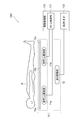
- FIG. 1A and FIG. 1B are schematic perspective views illustrating the motor-driven bed according to the embodiment.
- FIG. 2 is a schematic view illustrating an electric bed according to the embodiment.
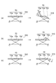
- FIGS. 3A to 3C are schematic views illustrating the operation of the electric bed according to the embodiment.
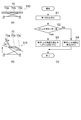
- FIGS. 4A to 4C are a schematic view and a flowchart illustrating the operation of the electric bed according to the embodiment.
- 5 (a) to 5 (c) are a schematic view and a flowchart illustrating the operation of the motor-driven bed according to the embodiment.
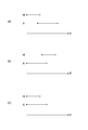
- FIGS. 6A to 6C are time charts illustrating the operation of the electric bed according to the embodiment.
- the electric bed 310 which concerns on embodiment is provided with the operation part 10 and the bottom 70.
- the operation unit 10 can operate the control of the bottom 70.
- the operation unit 10 is, for example, a remote controller of the electric bed 310.
- the operation unit 10 is, for example, a hand switch.
- the operation unit 10 may have various functions such as turning on and off the light, calling on the nurse or the carer, and turning on and off the power.
- the electric bed 310 is used, for example, in a hospital, a care facility, or a home.
- the bottom 70 includes, for example, a back section 70a, an upper leg section 70b, a lower leg section 70c, and the like.
- the angles of the back bottom 70a, the knee bottom 70b, and the leg bottom 70c can be changed.
- the bottom 70 includes a back bottom drive 71 a, a knee bottom drive 71 b, and a height drive 72.
- each of the back bottom drive 71a, the knee bottom drive 71b, and the height drive 72 includes an actuator.
- the back bottom drive unit 71a By driving the back bottom drive unit 71a, the back bottom 70a operates to change the back angle of the user P (person sleeping on the electric bed).
- the knee bottom drive unit 71b By driving the knee bottom drive unit 71b, the knee bottom 70b and the leg bottom 70c are operated, and the angle between these bottoms can be changed. Thereby, the angle of the knee of the user P can be changed.
- the angles between the respective bottoms may change in conjunction with each other.
- the height drive unit 72 By driving the height drive unit 72, the height of the bottom 70 (the distance between the floor surface and the bed surface) can be changed.
- the electric bed 310 includes a drive control unit 120.
- the drive control unit 120 includes a bottom control unit 121 and a height control unit 122.
- the back bottom drive unit 71 a and the knee bottom drive unit 71 b are electrically connected to the bottom control unit 121.
- the operations of the back bottom drive unit 71 a and the knee bottom drive unit 71 b are controlled based on the signal transmitted from the bottom control unit 121.
- the height driver 72 is electrically connected to the height controller 122.
- the operation of the height drive unit 72 is controlled based on the signal transmitted from the height control unit 122.
- the operation unit 10 is electrically connected to the drive control unit 120.
- the operation unit 10 is connected to the drive control unit 120 illustrated in FIG. 2 by the cable 15 illustrated in FIG.
- a control circuit may be provided between the operation unit 10 and the drive control unit 120.
- the operation unit 10 may be connected to the drive control unit 120 by wireless communication means.
- the operation unit 10 includes an operation surface 10a.
- Operation surface 10 a includes an operation receiving unit 20.
- the operation receiving unit 20 can receive the control operation of the bottom 70 of the motorized bed 310.
- the control operation is performed by, for example, an operator (user) of the operation unit 10.
- the operation receiving unit 20 includes a plurality of operation buttons.
- the angle ⁇ 1 of the back bottom 70a with respect to the horizontal surface increases.
- the overall angle of the bottom 70 and the angle between the knee bottom 70b and the leg bottom 70c also change in conjunction.
- the angle ⁇ 1 of the back bottom 70a with respect to the horizontal surface decreases.
- the button 23a for raising the “foot” is pressed, the angle ⁇ 2 of the knee bottom 70b with respect to the horizontal surface increases as shown in FIG. .
- the angle ⁇ 2 of the knee bottom 70b with respect to the horizontal surface decreases.
- a part of the leg bottom 70c is lowered as shown in FIG. The angle ⁇ 3 of the leg bottom 70c with respect to
- the bottom 70 is raised.
- the lowering button 24b for "height” is pressed, the bottom 70 is lowered.
- the angle ⁇ 1 and the angle ⁇ 2 change simultaneously. These changes are made by the action of the bottom 70.
- the above operation is performed while the operation button is kept pressed. This provides a safe operation.
- the operation reception unit 20 in addition to a switch having a mechanical contact, any input device such as an electrostatic type or an optical type (for example, a touch switch or the like) may be used.
- the reception of the operation in the operation reception unit 20 may include a method such as voice recognition.
- the voice generated by the operator for example, the user of the motorized bed 310) may be recognized, and the operation (control) of the motorized bed 310 may be performed based on the operation (control) by the voice.
- the display area 28 may be provided on the operation surface 10a.
- the display area 28 can display, for example, information on the bottom 70 of the motorized bed 310 (such as the angle and height of the bottom 70).
- the display area 28 may display information on the function or the operation state of the operation reception unit 20.
- the operation unit 10 may be provided with a hook 30.
- the hook 30 enables the operation unit 10 to be held by, for example, a side rail of the electric bed 310 or a bed grip.
- the angle of the bottom 70 changes.
- the motorized bed 310 raises the bottom 70 at least in part while the angle of the bottom 70 is changing when the height of the bottom is equal to or less than the first value.
- FIG. 4A, FIG. 4B, FIG. 5A, and FIG. 5B are schematic views illustrating the operation of the motorized bed.
- FIG.4 (c) and FIG.5 (c) are flowcharts which illustrate operation
- the first operation is the pressing of the up button 22a for "head”.
- the operation receiving unit 20 receives the first operation (step S1).
- the drive control unit 120 determines whether the height of the bottom 70 is equal to or less than the first value (step S2).
- the drive control unit 120 drives the back bottom drive unit 71a to increase the angle ⁇ 1 of the back bottom 70a, while the angle ⁇ 1 is increased.
- the height drive unit 72 is driven to raise the bottom 70 (step S3).
- step S3 for example, the bottom 70 moves from the state shown in FIG. 4 (a) to the state shown in FIG. 4 (b). If the height of the bottom 70 exceeds the first value, the drive control unit 120 drives the back bottom drive unit 71a to increase the angle ⁇ 1 of the back bottom 70a (step S4).
- the first operation is pressing the down button 23b on the "leg” with the knee bottom 70b and the leg bottom 70c horizontal.
- the operation reception part 20 receives 1st operation (step S11).
- the drive control unit 120 determines whether the height of the bottom 70 is equal to or less than the first value (step S12).
- the drive control unit 120 drives the knee bottom drive unit 71b to increase the angle ⁇ 3 of the leg bottom 70c, while the angle ⁇ 3 is increased.
- At least a part of the height drive unit 72 is driven to raise the bottom 70 (step S13).
- the bottom 70 moves from the state shown in FIG. 5 (a) to the state shown in FIG. 5 (b). If the height of the bottom 70 exceeds the first value, the drive control unit 120 drives the knee bottom drive unit 71b to increase the angle ⁇ 3 of the leg bottom 70c (step S14).
- the first value is preset, for example, before using the motorized bed 310. For example, when the height of the bottom 70 exceeds the first value, when the angle of the bottom 70 changes, the components included in the electric bed 310 or the components included in the electric bed 310 do not contact with the floor surface. .
- the first value is set to, for example, 10 cm or more and 65 cm or less.
- the electric bed concerning the following reference examples can be considered.
- the angle of the bottom 70 changes after the height of the bottom 70 becomes higher than the first value. That is, the operation of changing the angle of the bottom 70 intended by the user is performed after raising the bottom 70.
- the angle of the bottom 70 changes if the height of the bottom 70 is equal to or less than the first value. At least in part, the bottom 70 is raised. Therefore, the operation of changing the angle of the bottom 70 intended by the user is performed earlier than the motorized bed according to the reference example. According to this embodiment, the motorized bed 310 can be operated more in line with the user's intention.
- FIGS. 6A to 6C schematically show periods in which the height H of the bottom 70 and the angle A of the bottom 70 are changing.
- the angle of the bottom 70 starts to change after the bottom 70 starts to rise. Thereby, the above-mentioned contact at the time of changing the angle of bottom 70 can be avoided more certainly.
- the bottom 70 may start to rise after the angle of the bottom 70 starts to change. As a result, the action intended by the user is performed earlier. It is possible to operate the electric bed 310 more in accordance with the user's intention.
- the bottom 70 may start to rise at the same time as the angle of the bottom 70 starts to change. This makes it possible to operate the electric bed 310 more in line with the user's intention, while more reliably avoiding the above-mentioned contact when changing the angle of the bottom 70.
- the embodiment may include the following configuration (plan).
- (Configuration 1) It has a bottom and an operation reception unit, When the operation receiving unit receives the first operation, the bottom is increased at least in part while the angle of the bottom is changing, when the height of the bottom is equal to or less than a first value.
- Electric bed. (Configuration 2)
- the bottom includes a back bottom, The electric bed according to Configuration 1, wherein an angle of the back bottom with respect to a horizontal surface increases when the operation reception unit receives the first operation.
- (Configuration 3) The bottom includes a leg bottom, The electric bed according to Configuration 1, wherein an angle of the leg bottom with respect to a horizontal surface increases when the operation receiving unit receives the first operation.
Landscapes
- Health & Medical Sciences (AREA)
- Nursing (AREA)
- General Health & Medical Sciences (AREA)
- Life Sciences & Earth Sciences (AREA)
- Animal Behavior & Ethology (AREA)
- Public Health (AREA)
- Veterinary Medicine (AREA)
- Invalid Beds And Related Equipment (AREA)
Applications Claiming Priority (2)
| Application Number | Priority Date | Filing Date | Title |
|---|---|---|---|
| JP2017176960A JP7114233B2 (ja) | 2017-09-14 | 2017-09-14 | 電動ベッド |
| JP2017-176960 | 2017-09-14 |
Publications (1)
| Publication Number | Publication Date |
|---|---|
| WO2019054319A1 true WO2019054319A1 (ja) | 2019-03-21 |
Family
ID=65723664
Family Applications (1)
| Application Number | Title | Priority Date | Filing Date |
|---|---|---|---|
| PCT/JP2018/033397 Ceased WO2019054319A1 (ja) | 2017-09-14 | 2018-09-10 | 電動ベッド |
Country Status (2)
| Country | Link |
|---|---|
| JP (1) | JP7114233B2 (enExample) |
| WO (1) | WO2019054319A1 (enExample) |
Cited By (1)
| Publication number | Priority date | Publication date | Assignee | Title |
|---|---|---|---|---|
| JP2023524007A (ja) * | 2020-04-28 | 2023-06-08 | アヴィアーナ モレキュラー テクノロジーズ,エルエルシー | 感染性疾患を同定するための組成物および表面弾性波をベースとする方法 |
Citations (3)
| Publication number | Priority date | Publication date | Assignee | Title |
|---|---|---|---|---|
| JP2006109930A (ja) * | 2004-10-12 | 2006-04-27 | Iura Co Ltd | ベッド |
| JP2006129953A (ja) * | 2004-11-02 | 2006-05-25 | Paramount Bed Co Ltd | 電動ベッドの動作制御装置 |
| JP2016047087A (ja) * | 2014-08-27 | 2016-04-07 | パラマウントベッド株式会社 | 身体支持装置及びベッド装置 |
Family Cites Families (2)
| Publication number | Priority date | Publication date | Assignee | Title |
|---|---|---|---|---|
| GB2250189B (en) * | 1990-11-28 | 1993-11-24 | Nesbit Evans & Co Ltd | Beds |
| JP2010178783A (ja) | 2009-02-03 | 2010-08-19 | Aisin Seiki Co Ltd | ベッド装置 |
-
2017
- 2017-09-14 JP JP2017176960A patent/JP7114233B2/ja active Active
-
2018
- 2018-09-10 WO PCT/JP2018/033397 patent/WO2019054319A1/ja not_active Ceased
Patent Citations (3)
| Publication number | Priority date | Publication date | Assignee | Title |
|---|---|---|---|---|
| JP2006109930A (ja) * | 2004-10-12 | 2006-04-27 | Iura Co Ltd | ベッド |
| JP2006129953A (ja) * | 2004-11-02 | 2006-05-25 | Paramount Bed Co Ltd | 電動ベッドの動作制御装置 |
| JP2016047087A (ja) * | 2014-08-27 | 2016-04-07 | パラマウントベッド株式会社 | 身体支持装置及びベッド装置 |
Cited By (1)
| Publication number | Priority date | Publication date | Assignee | Title |
|---|---|---|---|---|
| JP2023524007A (ja) * | 2020-04-28 | 2023-06-08 | アヴィアーナ モレキュラー テクノロジーズ,エルエルシー | 感染性疾患を同定するための組成物および表面弾性波をベースとする方法 |
Also Published As
| Publication number | Publication date |
|---|---|
| JP7114233B2 (ja) | 2022-08-08 |
| JP2019051013A (ja) | 2019-04-04 |
Similar Documents
| Publication | Publication Date | Title |
|---|---|---|
| CN110621277B (zh) | 控制装置及电动家具 | |
| US9649234B2 (en) | Separable bed | |
| JP6329945B2 (ja) | ベッド装置 | |
| JP7419419B2 (ja) | 制御装置及び電動家具 | |
| JP2009533115A (ja) | 手術台制御のグループ化ユニットを含む電動手術台の操作装置 | |
| WO2018203476A1 (ja) | 電動家具 | |
| JP2022019820A (ja) | 電動ベッド | |
| WO2019054319A1 (ja) | 電動ベッド | |
| JP2003265540A (ja) | ベッド等のボトム動作切換方法 | |
| JP6886221B2 (ja) | 電動ベッド | |
| JP6800110B2 (ja) | 制御装置および電動家具 | |
| JP6340352B2 (ja) | ベッド装置 | |
| JP5707371B2 (ja) | ベッド装置 | |
| JP2018185991A (ja) | 制御装置及び電動家具 | |
| JP6916359B2 (ja) | 制御装置 | |
| JP6916358B2 (ja) | 制御装置 | |
| JP3001829B2 (ja) | 操作指令停止機能を有するスイッチ手段を備えた電動制御システム | |
| CN110870823A (zh) | 手术台 | |
| JP2020199336A (ja) | 制御装置 | |
| US10021992B2 (en) | Power adjustment and safety systems for power motion furniture | |
| JP2007097618A (ja) | 電位治療器における検電機能付きリモートコントローラ | |
| JP2017038672A (ja) | 操作装置、および、操作装置を備えた椅子体 | |
| KR20250131918A (ko) | 전동식 수술대의 리모트 컨트롤러 및 제어방법 |
Legal Events
| Date | Code | Title | Description |
|---|---|---|---|
| 121 | Ep: the epo has been informed by wipo that ep was designated in this application |
Ref document number: 18856514 Country of ref document: EP Kind code of ref document: A1 |
|
| NENP | Non-entry into the national phase |
Ref country code: DE |
|
| 122 | Ep: pct application non-entry in european phase |
Ref document number: 18856514 Country of ref document: EP Kind code of ref document: A1 |