WO2019049534A1 - 画像処理装置、テレビジョン受像機、画像処理方法、制御プログラム、および記録媒体 - Google Patents
画像処理装置、テレビジョン受像機、画像処理方法、制御プログラム、および記録媒体 Download PDFInfo
- Publication number
- WO2019049534A1 WO2019049534A1 PCT/JP2018/027556 JP2018027556W WO2019049534A1 WO 2019049534 A1 WO2019049534 A1 WO 2019049534A1 JP 2018027556 W JP2018027556 W JP 2018027556W WO 2019049534 A1 WO2019049534 A1 WO 2019049534A1
- Authority
- WO
- WIPO (PCT)
- Prior art keywords
- image signal
- gain
- adjusted
- image
- image processing
- Prior art date
- Legal status (The legal status is an assumption and is not a legal conclusion. Google has not performed a legal analysis and makes no representation as to the accuracy of the status listed.)
- Ceased
Links
Images








Classifications
-
- H—ELECTRICITY
- H04—ELECTRIC COMMUNICATION TECHNIQUE
- H04N—PICTORIAL COMMUNICATION, e.g. TELEVISION
- H04N9/00—Details of colour television systems
- H04N9/64—Circuits for processing colour signals
- H04N9/73—Colour balance circuits, e.g. white balance circuits or colour temperature control
-
- G—PHYSICS
- G02—OPTICS
- G02F—OPTICAL DEVICES OR ARRANGEMENTS FOR THE CONTROL OF LIGHT BY MODIFICATION OF THE OPTICAL PROPERTIES OF THE MEDIA OF THE ELEMENTS INVOLVED THEREIN; NON-LINEAR OPTICS; FREQUENCY-CHANGING OF LIGHT; OPTICAL LOGIC ELEMENTS; OPTICAL ANALOGUE/DIGITAL CONVERTERS
- G02F1/00—Devices or arrangements for the control of the intensity, colour, phase, polarisation or direction of light arriving from an independent light source, e.g. switching, gating or modulating; Non-linear optics
- G02F1/01—Devices or arrangements for the control of the intensity, colour, phase, polarisation or direction of light arriving from an independent light source, e.g. switching, gating or modulating; Non-linear optics for the control of the intensity, phase, polarisation or colour
- G02F1/13—Devices or arrangements for the control of the intensity, colour, phase, polarisation or direction of light arriving from an independent light source, e.g. switching, gating or modulating; Non-linear optics for the control of the intensity, phase, polarisation or colour based on liquid crystals, e.g. single liquid crystal display cells
- G02F1/133—Constructional arrangements; Operation of liquid crystal cells; Circuit arrangements
-
- G—PHYSICS
- G09—EDUCATION; CRYPTOGRAPHY; DISPLAY; ADVERTISING; SEALS
- G09G—ARRANGEMENTS OR CIRCUITS FOR CONTROL OF INDICATING DEVICES USING STATIC MEANS TO PRESENT VARIABLE INFORMATION
- G09G3/00—Control arrangements or circuits, of interest only in connection with visual indicators other than cathode-ray tubes
- G09G3/20—Control arrangements or circuits, of interest only in connection with visual indicators other than cathode-ray tubes for presentation of an assembly of a number of characters, e.g. a page, by composing the assembly by combination of individual elements arranged in a matrix no fixed position being assigned to or needed to be assigned to the individual characters or partial characters
-
- G—PHYSICS
- G09—EDUCATION; CRYPTOGRAPHY; DISPLAY; ADVERTISING; SEALS
- G09G—ARRANGEMENTS OR CIRCUITS FOR CONTROL OF INDICATING DEVICES USING STATIC MEANS TO PRESENT VARIABLE INFORMATION
- G09G3/00—Control arrangements or circuits, of interest only in connection with visual indicators other than cathode-ray tubes
- G09G3/20—Control arrangements or circuits, of interest only in connection with visual indicators other than cathode-ray tubes for presentation of an assembly of a number of characters, e.g. a page, by composing the assembly by combination of individual elements arranged in a matrix no fixed position being assigned to or needed to be assigned to the individual characters or partial characters
- G09G3/34—Control arrangements or circuits, of interest only in connection with visual indicators other than cathode-ray tubes for presentation of an assembly of a number of characters, e.g. a page, by composing the assembly by combination of individual elements arranged in a matrix no fixed position being assigned to or needed to be assigned to the individual characters or partial characters by control of light from an independent source
-
- G—PHYSICS
- G09—EDUCATION; CRYPTOGRAPHY; DISPLAY; ADVERTISING; SEALS
- G09G—ARRANGEMENTS OR CIRCUITS FOR CONTROL OF INDICATING DEVICES USING STATIC MEANS TO PRESENT VARIABLE INFORMATION
- G09G3/00—Control arrangements or circuits, of interest only in connection with visual indicators other than cathode-ray tubes
- G09G3/20—Control arrangements or circuits, of interest only in connection with visual indicators other than cathode-ray tubes for presentation of an assembly of a number of characters, e.g. a page, by composing the assembly by combination of individual elements arranged in a matrix no fixed position being assigned to or needed to be assigned to the individual characters or partial characters
- G09G3/34—Control arrangements or circuits, of interest only in connection with visual indicators other than cathode-ray tubes for presentation of an assembly of a number of characters, e.g. a page, by composing the assembly by combination of individual elements arranged in a matrix no fixed position being assigned to or needed to be assigned to the individual characters or partial characters by control of light from an independent source
- G09G3/36—Control arrangements or circuits, of interest only in connection with visual indicators other than cathode-ray tubes for presentation of an assembly of a number of characters, e.g. a page, by composing the assembly by combination of individual elements arranged in a matrix no fixed position being assigned to or needed to be assigned to the individual characters or partial characters by control of light from an independent source using liquid crystals
Definitions
- the present invention relates to an image processing apparatus for adjusting white balance, a television receiver including the image processing apparatus, an image processing method by the image processing apparatus, a control program for causing a computer to function as the image processing apparatus, and the control
- the present invention relates to a recording medium recording a program.
- an image processing apparatus which performs white balance adjustment on an image displayed on a display device.
- Patent Document 1 describes an image processing apparatus that corrects the color temperature of a white-based video signal having a predetermined or higher luminance and a predetermined or lower saturation.
- Local dimming control is a technology for controlling the brightness of the backlight for each local area of the screen.
- the local dimming control calculates the lighting rate of the backlight in the local area based on the input image, and adjusts and outputs the gradation of the image in the area according to the calculated lighting rate.
- an image including a dark achromatic local region is input.
- a low value such as 10% is set as the lighting rate of the backlight in the local area
- the gradation of the local area in the input image may be changed to near the maximum gradation.
- the high gradation of the area in the input image is not for expressing high luminance but for the purpose of suppressing the power consumption of the backlight and widening the dynamic range of the brightness of the image. .
- the image after the local dimming control is likely to include an area in which the gradation is changed from the image before the control. Therefore, when the white balance is adjusted with respect to an image including an area where the gradation is changed, an image having a sense of incongruity may be obtained.
- the present invention has been made in view of the above problems, and an object thereof is to provide a technique for adjusting white balance more appropriately for an image after local dimming control.
- an image processing apparatus is an image processing apparatus that adjusts white balance, and is an adjusted image signal whose tone has been adjusted according to local dimming control of a backlight.
- a first adjustment unit that generates a first image signal whose white balance is adjusted using a first gain for each of the primary color signals in the above, and the first gain for each of the primary color signals in the adjusted image signal
- a second adjustment unit that generates a second image signal whose white balance has been adjusted using a second gain in which the gain for at least one of the primary color signals is changed to a higher value
- a weighting interpolation unit that outputs an image signal obtained by performing weighting interpolation on the second image signal based on the backlight gradation by the local dimming control; Obtain.
- an image processing method for adjusting white balance, which is an adjusted image signal whose gray level is adjusted according to local dimming control of a backlight.
- FIG. 1 It is a block diagram which shows the principal part structure of the television receiver which concerns on Embodiment 1 of this invention.
- (A), (b) and (c) is a figure which shows an example of the external appearance of the television which concerns on Embodiment 1 of this invention.
- (A) is a graph which shows an example of a gain when not adjusting a white balance.
- (B) is a graph which shows an example of the 1st gain used in Embodiment 1 of the present invention.
- (A), (b) and (c) are each a graph showing an example of the second gain.
- Embodiment 1 of this invention It is a block diagram which shows the structural example of the weighting interpolation part in Embodiment 1 of this invention. It is a graph showing weighting interpolation in Embodiment 1 of the present invention. It is a graph which shows an example of the weighting coefficient calculated based on a backlight gradation in Embodiment 1 of this invention. It is a flowchart which shows the flow of the process which the television which concerns on Embodiment 1 of this invention performs. It is a flowchart which shows the flow of the process which the image processing apparatus in Embodiment 1 of this invention performs. It is a block diagram which shows the principal part structure of the television receiver which concerns on Embodiment 2 of this invention.
- Embodiment 2 of this invention It is a block diagram which shows the structural example of the weighting interpolation part in Embodiment 2 of this invention. It is a graph which shows an example of the weighting coefficient calculated based on the saturation in Embodiment 2 of this invention. It is a flowchart which shows the flow of the process which the image processing apparatus in Embodiment 2 of this invention performs. It is a block diagram which shows the principal part structure of the television receiver which concerns on Embodiment 3 of this invention.
- Embodiment 1 Hereinafter, embodiments of the present invention will be described in detail.
- FIG. 1 is a block diagram showing the main configuration of a television receiver (display device) 1 according to a first embodiment.
- the television receiver 1 (hereinafter, simply referred to as “television 1”) is an apparatus that acquires an image signal and displays an image according to the acquired image signal on a display unit having a backlight.
- the television 1 includes an image signal acquisition unit 10, a display unit 11, a local dimming control unit 12, a first adjustment unit 13, a second adjustment unit 14, a weighting interpolation unit 15, a storage unit 16, and Operation reception unit 17 is included.
- the first adjustment unit 13, the second adjustment unit 14, and the weighting interpolation unit 15 constitute an image processing apparatus 100.
- the image signal acquisition unit 10 is an interface for acquiring an image signal.
- an image signal acquired by the image signal acquisition unit 10 a tuner signal acquired through a tuner, an HDMI signal acquired through HDMI (registered trademark) (High-Definition Multimedia Interface: High-definition Multimedia Interface), Or CVBS (Composite Video, Blanking, and Sync) signals.
- HDMI registered trademark
- CVBS Composite Video, Blanking, and Sync
- the display unit 11 is a display device that displays an image, and is realized by a transmissive screen having a backlight.
- a transmissive screen include, but are not limited to, a liquid crystal panel and an organic electro luminescence (EL) display.
- EL organic electro luminescence
- the white balance of the image displayed by the display unit 11 can be adjusted by adjusting the value of the gain for each primary color.
- the backlight which the display part 11 has consists of several light emission blocks.
- Each light emission block can control the lighting rate individually.
- the lighting rate of the light emitting block corresponds to an example of the backlight gradation in the present invention.
- the light source which comprises each light emission block although LED (light emitting diode) and a cold cathode tube are mentioned, for example, it is not restricted to these.
- the light emission block is disposed on the back side of the local area where the transmissive screen of the display unit 11 is divided.
- the light emission block mainly emits light to the local region at the lighting rate determined by the local dimming control unit 12 described later. With the control of the lighting rate of each light emission block, the gradation (brightness) of the image displayed in the local region corresponding to the light emission block may be adjusted.
- the local dimming control unit 12 calculates the lighting rate of each light emission block of the backlight based on the image signal acquired by the image signal acquisition unit 10. In addition, the local dimming control unit 12 adjusts the gradation of each local region of the image signal based on the calculated lighting rate.
- the image signal whose gradation has been adjusted by the local dimming control unit 12 will also be referred to as adjusted image signals (R, G, B). Details of the local dimming control unit 12 will be described later.
- the first adjustment unit 13 adjusts the white balance using the first gain with respect to each primary color signal in the adjusted image signal (R, G, B) whose gradation is adjusted in accordance with the local dimming control of the backlight. To generate a first image signal.
- Each primary color signal is a signal representing red (R), green (G), and blue (B), respectively.
- the first image signal is an image of chromaticity priority as compared to the second image signal described below. Details of the first adjustment unit 13 will be described later.
- the second adjustment unit 14 adjusts the white balance using the second gain with respect to each primary color signal in the adjusted image signal (R, G, B) whose gradation has been adjusted according to the local dimming control of the backlight.
- the second adjustment unit 14 may generate the second image signal using the second gain when the adjusted image signal (R, G, B) satisfies the high luminance condition. In this case, when the high luminance condition is not satisfied, the second adjustment unit 14 may generate the first image signal using the first gain.
- the second image signal is an image with luminance priority as compared to the above-described first image signal. Details of the second adjustment unit 14 will be described later.
- the weighting interpolation unit 15 performs weighting interpolation on the first image signal (R1, G1, B1) and the second image signal (R2, G2, B2) based on the backlight gradation by the local dimming control.
- an image signal obtained by performing weighted interpolation will also be described as an image signal (R_out1, G_out1, B_out1). Details of the weighting interpolation unit 15 will be described later.
- the storage unit 16 is a device capable of storing data. Specifically, the storage unit 16 stores a first gain, a second gain, and the like used by the first adjustment unit 13 and the second adjustment unit 14 respectively.
- the operation reception unit 17 receives a user's operation and outputs operation information indicating the operation.
- the operation reception unit 17 is realized by an infrared signal light receiving unit that receives an infrared signal transmitted from the remote controller, a switch, a touch pad, and the like.
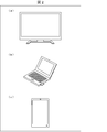
- FIG. 2 is a view showing an example of the appearance of a display device realized as part of the television 1 according to the first embodiment.
- the display device realized as part of the television 1 may be configured by a display device that displays an image signal, as shown in FIG. 2A.
- the display device realized as a part of the television 1 may be configured by a personal computer, as shown in FIG. 2 (b).
- the display device realized as part of the television 1 may be configured by a portable information terminal device as shown in FIG. 2C.
- the appearance of the display device realized as part of the television 1 and the configuration thereof are not limited to this.
- the local dimming control unit 12 can be configured by, for example, functional blocks shown in FIG. In FIG. 3, the local dimming control unit 12 includes a lighting rate calculation unit 121, a distribution characteristic calculation unit 122, and an image tone adjustment unit 123.
- the lighting ratio calculation unit 121 calculates the lighting ratio of each light emission block of the backlight based on the input image signal. For example, the lighting ratio calculation unit 121 may calculate the lighting ratio based on the maximum gradation value in the local region of the image signal corresponding to each light emission block. However, the calculation method of the lighting rate based on the image signal is not limited to this, and various known methods can be applied. In addition, the lighting rate calculation unit 121 outputs the backlight coefficient L based on the lighting rate to the weighting interpolation unit 15.
- the backlight coefficient L may be a numerical value of 0 or more and 1 or less, and the lighting rate may be converted into a numerical value of 0 or more and 1 or less.
- the distribution characteristic calculation unit 122 calculates the distribution characteristic of the brightness by the backlight based on the lighting rate of each light emitting block and the characteristic of the light source of each light emitting block. For example, the distribution characteristic calculation unit 122 calculates the range and the degree to which light leaks from each light emitting block to its neighborhood according to the characteristic of the light source. Then, the distribution characteristic calculation unit 122 can obtain the distribution characteristic of the brightness by the backlight by superposing the range and degree to which light leaks from the other light emission blocks with the lighting rate of each light emission block. is there.
- the image gradation adjustment unit 123 adjusts the gradation of the input image signal based on the distribution characteristic of brightness by the backlight, and outputs an adjusted image signal (R, G, B).
- the adjustment process of gradation may be performed by calculation, table reference, etc., and various known methods can be applied.
- the first gain used by the first adjustment unit 13 will be described.
- the first gain is determined as follows with respect to the gain when the white balance is not adjusted (ie, no adjustment).
- the first gain is set such that the value of the gain for any of at least one of the unadjusted gains is lower than that in the unadjusted case.
- the non-adjustment gain is set, for example, such that the luminance of the image to be displayed becomes the highest when the gradation of the input image signal is the highest gradation value.
- the first gain is determined to be the same as in the case where the gain value for any of the primary color signals is not adjusted, and is set lower than in the case where the gain values for the other two primary color signals are not adjusted. It may be done.
- the first image signal whose white balance has been adjusted using such a first gain represents a chromaticity priority image whose luminance is lowered but whose chromaticity is appropriately adjusted, as compared to the case where no adjustment is made.
- the first image signal is also referred to as (R1, G1, B1).
- the horizontal axis represents the input adjusted image signal (input)
- the vertical axis represents the first image signal (output) output using the gain. ing.
- an unadjusted gain is determined as shown in the graph of FIG. 4 (a).
- the gain of each primary color signal is the same.
- the first gain is determined as shown in FIG. 4B, as an example.
- the gain for green (R) is the same as the unadjusted gain.
- the gains for red (R) and blue (B) are lower than in the unadjusted case.
- the second gain used by the second adjustment unit 14 will be described.
- the second gain is determined with respect to the first gain as follows.
- the second gain is set such that the value of the gain for at least one of the primary colors of the first gain is higher than the first gain.
- the second gain is set such that at least one of the gains for each primary color signal set lower than in the case of no adjustment among the first gains is higher than the first gain. It may be one.
- the second adjustment unit 14 may obtain the second gain by calculation or table reference.
- the second image signal whose white balance has been adjusted using such a second gain has a lower degree of adjustment of the chromaticity as compared to the image represented by the first image signal, but the luminance is high and the luminance priority is high. Represents an image.
- the second image signal is also described as (R2, G2, B2).
- the second gain will be described with reference to FIG. 5 (a) to 5 (c), the horizontal axis represents the input adjusted image signal (input), and the vertical axis represents the second image signal (output) output using the gain. ing.
- the second gain is determined as shown in FIG. 5 (a), (b) or (c).
- the second gain for green (G) is set equal to the first gain. Also, the second gains for red (R) and blue (B) are set higher than the first gain shown by the broken line and lower than in the case of no adjustment.
- the second image signal is an image with luminance priority over the first image signal from the lowest tone value to the highest tone value.
- the condition of being equal to or higher than a predetermined gradation value (L1 for R and L2 for B) is applied as the high luminance condition. Also, the second gain for green (G) is set equal to the first gain.
- the second gain for red (R) is set to the same value as the first gain from the lowest tone value to the tone value L1. Further, the second gain for red (R) is set from the tone value L1 to the maximum tone value, not less than the first gain, and not greater than the case of no adjustment. Further, the second gain for red (R) is set so that the luminance is maximum (the same as in the case of no adjustment) in the case of the maximum gradation value.
- the second gain for blue (B) is set to the same value as the first gain from the lowest tone value to the tone value L2.
- the second gain for blue (B) is set from the tone value L2 to the maximum tone value, not less than the first gain and not greater than the case of no adjustment.
- the second gain for blue (B) is set so that the luminance is maximum (the same as in the case of no adjustment) in the case of the maximum gradation value.
- the second image signal is generated when red (R) of the adjusted image signal is lower than the gradation value L1 and blue (B) is lower than the gradation value L2. Is a color-first image. Further, the second image signal is an image with priority in luminance when red (R) of the adjusted image signal is equal to or greater than the gradation value L1 or blue (B) is equal to or larger than the gradation value L2.
- the condition of being equal to or higher than a predetermined gradation value (L3 for R and L4 for B) is applied as the high luminance condition. Also, the second gain for green (G) is set equal to the first gain.
- the second gain for red (R) is set to the same value as the first gain from the lowest tone value to the tone value L3. Further, the second gain for red (R) is set from the tone value L3 to the maximum tone value, not less than the first gain, and not greater than the case of no adjustment. In addition, the second gain for red (R) is set to a value lower than the maximum luminance (lower value than no adjustment) in the case of the maximum gradation value.
- the second gain for blue (B) is set to the same value as the first gain from the lowest tone value to the tone value L4. Further, the second gain for blue (B) is set from the tone value L4 to the maximum tone value, not less than the first gain, and not greater than the case of no adjustment. In addition, the second gain for blue (B) is set to a value lower than the maximum luminance (lower value than no adjustment) in the case of the maximum gradation value.
- the second image signal is generated when red (R) of the adjusted image signal is lower than the gradation value L1 and blue (B) is lower than the gradation value L2. Is a color-first image. Further, the second image signal is an image with priority in luminance when red (R) of the adjusted image signal is equal to or greater than the gradation value L1 or blue (B) is equal to or larger than the gradation value L2.
- the gradation value L1 and the gradation value L2 may not necessarily be different values, and may be the same.
- the gradation value L3 and the gradation value L4 may not necessarily be different values, and may be the same.
- the weighting interpolation unit 15 is configured by functional blocks shown in FIG. In FIG. 6, the weighting interpolation unit 15 includes a weighting coefficient calculation unit 151 and a weighting unit 152.
- the weighting coefficient calculation unit 151 calculates the weighting coefficient W L based on the backlight coefficient L output from the local dimming control unit 12.
- the weighting factor W L is calculated, for example, by the following equation (1).
- W L f (L) (1)
- the function f is a function that calculates a larger value as the backlight gradation (backlight coefficient L) is higher.
- Weighting section 152 uses the weighting coefficient W L, performs weighting interpolation on the first image signal (R1, G1, B1) and the second image signal (R2, G2, B2).
- the weighting interpolation is performed such that the weighting of the second image signal (R2, G2, B2) is larger as the weighting coefficient W L is larger.
- weighted interpolation for the red (R) primary color signal is performed by the following equation (2).
- R_out1 R1 ⁇ (1-W L ) + R2 ⁇ W L (2)
- the formula which substituted character R in Formula (2) to G or B is applicable also to each primary color signal of green (G) and blue (B).
- x 0 represents the high luminance condition used by the second adjustment unit 14. That is, in this case, the high brightness condition is that the gradation value is x0 or more.
- the weighting interpolation unit 15 outputs the first image signal adjusted by the first adjustment unit 13. Ru. This is because, when the input value is lower than x0, the second adjusting unit 14 also outputs the first image signal adjusted using the second gain which is the same as the first gain.
- the weighted interpolation unit 15 outputs an output value weighted between the first image signal and the second image signal.
- the function f used by the weighting coefficient calculation unit 151 may be a linear function or a non-linear function.
- An example of the non-linear function f is shown in FIG. 8, a non-linear function f, the backlight coefficient L is larger than the range (high luminance region), W L is defined to be closer to 1, the smaller area, as W L becomes closer to 0 It is fixed.
- the weighting interpolation unit 15 can generate an image signal closer to the second image signal with luminance priority as the area where the backlight is brighter Will be output.
- the weighting interpolation unit 15 outputs an image signal closer to the chromaticity-first image signal as the region where the backlight is darker.
- FIG. 9 is a flowchart showing a flow of processing performed by the television 1 according to the first embodiment. The process performed by the television 1 will be described with reference to FIG.
- Step S1 The image signal acquisition unit 10 acquires an image signal.
- the image signal acquisition unit 10 outputs the acquired image signal to the local dimming control unit 12.
- Step S2 The local dimming control unit 12 calculates the lighting rate of each light emission block of the backlight based on the image signal acquired in step S1.
- the local dimming control unit 12 also outputs adjusted image signals (R, G, B) in which the gradation of each local area of the image signal is adjusted based on the calculated lighting rate.
- Step S3 The image processing apparatus 100 receives the backlight coefficient L based on the lighting rate calculated in step S2 and the adjusted image signals (R, G, B), adjusts the white balance, and outputs an image signal. Details of this step will be described later.
- Step S4 The display unit 11 causes each light emission block of the backlight to emit light based on the lighting rate calculated in step S2. Further, the image signal whose white balance has been adjusted in step S3 is displayed on the screen.
- FIG. 10 is a flowchart illustrating the flow of processing performed by the image processing apparatus 100 according to the first embodiment.
- Step S301 The first adjustment unit 13 adjusts the white balance of the adjusted image signal (R, G, B) output in step S 2 using the first gain, and the first image signal (R 1, chromaticity priority) with priority to chromaticity. Generate G1, B1).
- Step S302 The second adjustment unit 14 adjusts the white balance of the adjusted image signal (R, G, B) output in step S 2 using the second gain, and the second image signal (R 2, G 2) with luminance priority , B2).
- Step S303 The weighting coefficient calculation unit 151 calculates the weighting coefficient W L based on the backlight coefficient L corresponding to the lighting rate calculated in step S2.
- Step S304 Weighting unit 5, using the weighting coefficient W L, by performing weighted interpolation with respect to the first image signal (R1, G1, B1) and a second image signal (R2, G2, B2), the image signal (R_out1 , G_out1, B_out1) are generated and output.
- the television 1 according to the present embodiment can more appropriately adjust the white balance with respect to the image after the local dimming control.
- the first adjustment unit 13 generates a first image signal whose white balance has been adjusted using a first gain with respect to the adjusted image signal after the local dimming control. Further, when the adjusted image signal satisfies the high luminance condition, the second adjusting unit 14 generates a second image signal in which the white balance is adjusted using the second gain.
- the second gain is set to a value obtained by changing the gain for at least one of the primary colors of the first gain to a higher value.
- the first image signal becomes a chromaticity-first image as compared to the second image signal.
- the second image signal is an image with luminance priority as compared to the first image signal.
- the weighting interpolation unit 15 outputs, to the first image signal with priority to chromaticity and the second image signal with priority to brightness, the image signal weighted and interpolated based on the backlight gradation determined by the local dimming control. It is from.
- the present embodiment in a local region where local dimming control is performed such that the backlight is dark, an image with priority to chromaticity is displayed even if the gradation value of the adjusted image signal is high. For this reason, the present embodiment reduces unnatural changes in tint due to adjustment of the white balance with respect to the image after local dimming control.
- the function f used by the weighting interpolation unit 15 is not limited to these.
- the weighting interpolation unit 15 performs weighting interpolation using Equation (2).
- the processing of weighting interpolation performed by the weighting interpolation unit 15 is not limited to the processing based on the equation (2).
- dR represents the difference between the first image signal R1 and the second image signal R2 with respect to the input value R of the maximum tone value.
- the weighting interpolation unit 15 may perform weighting interpolation using table reference, various arithmetic operations, arbitrary linear interpolation, or a combination thereof.
- the condition based on the gradation value of the adjusted image signal is used as the high luminance condition used by the second adjusting unit 14 .
- the high brightness condition may be a condition based on the brightness of the adjusted image signal.
- the second adjusting unit may generate a second image signal whose white balance is adjusted using the second gain.
- the high brightness condition may be individually defined for each of the R, G, and B primary color signals.
- the second adjustment unit 14 may store the difference information of the second gain with respect to the first gain, and may obtain the second gain based on the first gain and the difference information. . This reduces the amount of information to be stored to determine the second gain.
- the weighting interpolation unit 25 is replaced with the weighting interpolation unit 15 with respect to the configuration of the television 1 according to the first embodiment shown in FIG. The difference is in the inclusion.
- the first adjustment unit 13, the second adjustment unit 14, and the weighting interpolation unit 25 constitute an image processing apparatus 200.
- the weighting interpolation unit 25 performs backlight gradation by local dimming control on the first image signal (R1, G1, B1) and the second image signal (R2, G2, B2), and the adjusted image signal (R, G). Weighting interpolation is performed based on the saturations of B,. Also, the weighting interpolation unit 25 outputs image signals (R_out2, G_out2, B_out2) obtained as a result of performing the weighting interpolation.
- the weighting interpolation unit 25 can be configured by the functional block shown in FIG. As shown in FIG. 12, the weighting interpolation unit 25 includes a first weighting coefficient calculation unit 251, a second weighting coefficient calculation unit 253, and a weighting unit 252.
- the first weighting coefficient calculation unit 251 is configured in the same manner as the weighting coefficient calculation unit 151 in the first embodiment. That is, the first weighting coefficient calculation unit 251 calculates the weighting coefficient W L based on the backlight coefficient L output from the local dimming control unit 12.
- the second weighting coefficient calculation unit 253 calculates the weighting coefficient W S based on the saturation of the adjusted image signal.
- the weighting factor W S is calculated by the following equation (3).
- W S f S (S) (3)
- the function f s is a function that calculates a larger value as the saturation is lower.
- MIN (R, G, B) represents the minimum value among R, G, B.
- MAX (R, G, B) represents the maximum value among R, G, B.
- Weighting unit 252 by using the weighting coefficient W L and the weighting factor W S, performs weighting interpolation on the first image signal (R1, G1, B1) and the second image signal (R2, G2, B2).
- the weighting factor W used by the weighting interpolation is determined by the following equation (4).
- W W L ⁇ W S (4)
- weighted interpolation is performed, for example, on the primary color signal of red (R) by the following equation (5).
- R_out1 R1 ⁇ (1-W) + R2 ⁇ W (5)
- the equation in which the letter R in the equation (5) is replaced by G or B is also applicable to each of the primary color signals of green (G) and blue (B).
- the function f S used by the second weighting factor calculator 253 may be a linear function or a non-linear function.
- An example of the non-linear function f S is shown in FIG. 13, non-linear function f S is the saturation S is smaller than the range (low saturation region), W S is defined to be close by 1, the larger range, so that W S becomes closer to 0 It is defined in By using the weighting factor W S based on such saturation, the weighting interpolation unit 25 outputs an image signal closer to the luminance priority second image signal as the region with lower saturation is.
- the weighting interpolation unit 25 outputs an image signal closer to the chromaticity-first image signal as the area having higher saturation is. In other words, for example, the weighting interpolation unit 25 outputs an image signal close to the second image signal with luminance priority over the first embodiment if the saturation is low to some extent even in a region where the backlight is relatively dark. Become. In addition, the weighting interpolation unit 25 outputs an image signal close to the first image signal of chromaticity priority as compared with the first embodiment if the saturation is high to some extent even in a region where the backlight is relatively bright.
- FIG. 14 is a flowchart illustrating the flow of processing performed by the image processing apparatus 200 according to the second embodiment.
- the image processing apparatus 200 operates in the same manner as the image processing apparatus 100 in the first embodiment from step S301 to step S302. Thereby, the first image signal (R1, G1, B1) of chromaticity priority and the second image signal (R2, G2, B2) of luminance priority are generated.
- Step S323 The first weighting coefficient calculation unit 251 calculates the weighting coefficient W L based on the backlight coefficient L corresponding to the lighting rate calculated in step S2.
- Step S324 The second weighting coefficient calculation unit 253 calculates the saturation S from the adjusted image signals (R, G, B) output in step S2, and calculates the weighting coefficient W S based on the calculated saturation S.
- Step S325) The weighting interpolation unit 15 generates a first image signal (R1, G1, B1) and a second image signal (R2, G2, B2) using a weighting factor W obtained based on the weighting factor W L and the weighting factor W S. Perform weighted interpolation. Then, the weighting interpolation unit 15 outputs the image signals (R_out2, G_out2, B_out2) obtained by the weighting interpolation.
- the television 2 according to the present embodiment can adjust the white balance more appropriately to the image after the local dimming control.
- the weighting interpolation unit 25 being based on the backlight gradation determined by the local dimming control, the first image signal of chromaticity priority and the second image signal of luminance priority are This is because the image signal weighted and interpolated based on the degree is output.
- the white balance is adjusted in consideration of the backlight gradation, in particular, for a white-based image signal (that is, an image signal with low saturation).
- a white-based image signal that is, an image signal with low saturation.
- the television (display device) 3 is a first adjustment unit instead of the first adjustment unit 13 in the configuration of the television 1 according to the first embodiment shown in FIG. 1 as shown in FIG. 33 differs in that it includes a second adjustment unit 34 in place of the second adjustment unit 14, a weighting interpolation unit 35 in place of the weighting interpolation unit 15, and an operation reception unit 37 in place of the operation reception unit 17.
- the first adjustment unit 33, the second adjustment unit 34, and the weighting interpolation unit 35 constitute an image processing apparatus 300.
- the operation reception unit 37 acquires a first gain based on an input of the user, and stores the first gain in the storage unit 16. In addition, the operation reception unit 37 acquires a high brightness condition based on an input of the user, and stores the high brightness condition in the storage unit 16.
- the information that can be input as the high luminance condition may be, for example, a threshold of gradation for each primary color signal.
- the operation reception unit 37 acquires information indicating on / off of the image with priority to luminance and stores the information in the storage unit 16.
- the first adjustment unit 33 differs from the first adjustment unit 13 in the first embodiment in that the first adjustment unit 33 uses a first gain based on an input of the user as the first gain.
- the other configuration is the same as that of the first adjustment unit 13, and thus the detailed description will be omitted.
- the second adjustment unit 34 is different from the second adjustment unit 14 in the first embodiment in that the second adjustment unit 34 uses a high luminance condition based on an input of the user as the high luminance condition.
- the other configuration is the same as that of the second adjustment unit 14, and thus the detailed description will be omitted.
- the weighting interpolation unit 35 is configured in the same manner as the weighting interpolation unit 15 in the first embodiment and performs weighting interpolation when the information representing ON / OFF of the luminance priority image is set to ON. In addition, the weighting interpolation unit 35 outputs the first image signal without performing the weighting interpolation when the information representing the on / off of the luminance priority image is set to off.
- the adjustment of the white balance on the image after the local dimming control can be performed in accordance with the preference of the user.
- control blocks of the television receivers 1, 2 and 3 are formed in an integrated circuit (IC chip) or the like. It may be realized by the above-described logic circuit (hardware) or software.
- the television receivers 1, 2, and 3 each include a computer that executes instructions of a program that is software that implements each function.
- the computer includes, for example, at least one processor (control device) and at least one computer readable storage medium storing the program. Then, in the computer, the processor reads the program from the recording medium and executes the program to achieve the object of the present invention.
- a CPU Central Processing Unit
- the processor reads the program from the recording medium and executes the program to achieve the object of the present invention.
- a CPU Central Processing Unit
- the processor can be used as the processor.
- a recording medium a tape, a disk, a card, a semiconductor memory, a programmable logic circuit or the like can be used besides “a non-temporary tangible medium”, for example, a ROM (Read Only Memory).
- a RAM Random Access Memory
- the program may be supplied to the computer via any transmission medium (communication network, broadcast wave, etc.) capable of transmitting the program.
- any transmission medium communication network, broadcast wave, etc.
- one aspect of the present invention can also be realized in the form of a data signal embedded in a carrier wave in which the program is embodied by electronic transmission.
- An image processing apparatus (100) is an image processing apparatus that adjusts white balance, and each primary color signal (R) is adjusted in the adjusted image signal whose gradation is adjusted according to local dimming control of the backlight.
- G, B a first adjustment unit (13) that generates a first image signal (R1, G1, B1) whose white balance is adjusted using a first gain, and each of the adjustment image signals
- a second image signal (R2, G2, and so on) whose white balance has been adjusted using a second gain obtained by changing the gain for at least one of the first gains to a higher value with respect to the primary color signal.
- a second adjusting unit (14) for generating B2), the local dimming control for the first image signal (R1, G1, B1) and the second image signal (R2, G2, B2) Image signal by weighting interpolation based on the backlight gradation by (R_out1, G_out1, B_out1) comprises weighting interpolation section for outputting (15) a.
- the image processing apparatus includes the first image signal of chromaticity priority generated by the first adjustment unit and the second image signal of luminance priority generated by the second adjustment unit.
- weighted interpolation in accordance with the backlight gradation by local dimming control is performed. Therefore, the image processing apparatus according to this aspect can adjust the white balance more than chromaticity priority or luminance priority according to the backlight gradation with respect to the image after the local dimming control, and the image is more appropriate. Can be output.
- the weighting interpolation unit in aspect 1 may increase the weighting of the second image signal as the backlight gradation is higher.
- the image processing apparatus displays an image closer to the first image signal with priority to chromaticity as the area where the backlight is darker controlled by the local dimming control. Therefore, the image processing apparatus according to the present aspect adjusts the white balance not with priority to luminance but to chromaticity as long as the backlight is dark, even in a local region changed to high gradation by local dimming control. , Unnatural color change can be suppressed.
- the weighting interpolation unit according to aspect 1 or aspect 2 performs the weighting based on the saturation of the adjusted image signal in addition to being based on the backlight gradation. Interpolation may be performed.
- the image processing apparatus performs the white balance adjustment based on the backlight gradation determined by the local dimming control, based on the saturation of the adjusted image signal. Therefore, the image processing apparatus according to this aspect can output a more appropriate image.
- the weighting interpolation unit in aspect 3 may increase the weighting of the second image signal as the saturation is lower.
- the image processing apparatus performs the white balance adjustment based on the backlight gradation determined by the local dimming control on the adjusted image signal of the white saturation which is lower in saturation. It will be. Therefore, the image processing apparatus according to the present aspect can further suppress unnatural color change in adjusting the white balance to the image after the local dimming control.
- the second adjustment unit according to any one of aspects 1 to 4 is configured to receive the second gain when the adjusted image signal satisfies a predetermined high luminance condition.
- the second image signal adjusted in white balance may be generated to generate the second image signal.
- the image processing apparatus outputs the first image signal of chromaticity priority for an adjusted image signal that does not satisfy the high luminance condition. Further, the image processing apparatus according to the present aspect can adjust the white balance with respect to the chromaticity priority or the luminance priority according to the backlight gradation with respect to the adjusted image signal that satisfies the high luminance condition.
- the second adjustment unit may calculate the second gain based on difference information with respect to the first gain. Good.
- the image processing apparatus can reduce the volume of information to be stored for use in the second adjustment unit.
- the weighting interpolation unit in the case where the information input by the user indicates that the second image signal is to be applied, the weighting interpolation unit according to any one of aspects 1 to 6 is the weighting
- the first image signal may be output when the interpolation is performed and the information input by the user indicates that the second image signal is not applied.
- the image processing apparatus can determine whether or not to apply an image whose white balance has been adjusted with priority to luminance in accordance with the preference of the user.
- the first adjustment unit according to any one of aspects 1 to 7 adjusts the white balance by using information as input by the user as the first gain.
- a first image signal may be generated.
- the image processing apparatus can output an image according to the user's preference when adjusting the white balance with priority to chromaticity according to the backlight gradation.
- the display device (1) according to aspect 9 of the present invention performs the local dimming control on the input image signal to generate the adjusted image signal, and any one of aspect 1 to aspect 8. And an image processing apparatus.
- a television receiver (1) according to aspect 10 of the present invention includes the display device according to aspect 9 above.
- An image processing method is an image processing method for adjusting white balance, comprising: each primary color signal in an adjusted image signal whose gradation has been adjusted according to local dimming control of a backlight; A first adjustment step of generating a first image signal whose white balance is adjusted using a gain of 1, and at least one of the first gains among the first gains for each of the primary colors in the adjusted image signal A second adjustment step of generating a second image signal whose white balance is adjusted using a second gain in which the gain for the pixel is changed to a higher value, and for the first image signal and the second image signal, And an image signal output step of outputting an image signal which has been subjected to weighted interpolation based on the backlight gradation by the local dimming control.
- the image processing method according to this aspect has the same effect as the image processing device according to aspect 1 above.
- the image processing apparatus may be realized by a computer.
- the computer is operated as each unit (software element) included in the image processing apparatus.
- a control program for realizing the image processing apparatus by a computer, and a computer readable recording medium storing the control program fall within the scope of the present invention.
Landscapes
- Engineering & Computer Science (AREA)
- Physics & Mathematics (AREA)
- General Physics & Mathematics (AREA)
- Theoretical Computer Science (AREA)
- Computer Hardware Design (AREA)
- Chemical & Material Sciences (AREA)
- Signal Processing (AREA)
- Multimedia (AREA)
- Crystallography & Structural Chemistry (AREA)
- Nonlinear Science (AREA)
- Mathematical Physics (AREA)
- Optics & Photonics (AREA)
- Liquid Crystal Display Device Control (AREA)
- Control Of Indicators Other Than Cathode Ray Tubes (AREA)
- Processing Of Color Television Signals (AREA)
- Liquid Crystal (AREA)
Abstract
ローカルディミング制御後の画像に対して、より適切にホワイトバランスを調整する技術を提供すること。バックライトのローカルディミング制御に伴い階調が調整された調整画像信号における各原色信号に対して、第1のゲインを用いてホワイトバランスを調整した第1画像信号を生成する第1調整部(13)と、調整画像信号における各原色信号に対して、第1のゲインのうち少なくとも何れかの原色信号に対するゲインをより高い値に変更した第2のゲインを用いて、ホワイトバランスを調整した第2画像信号を生成する第2調整部(14)と、第1画像信号及び第2画像信号に対して、ローカルディミング制御によるバックライト階調に基づき重み付け補間を行った画像信号を出力する重み付け補間部(15)と、を備える。
Description
本発明は、ホワイトバランスを調整する画像処理装置、当該画像処理装置を含むテレビジョン受像機、当該画像処理装置による画像処理方法、当該画像処理装置としてコンピュータを機能させるための制御プログラム、および当該制御プログラムを記録した記録媒体に関する。
一般に、表示装置に表示される画像に対して、ホワイトバランスの調整を行う画像処理装置が知られている。
例えば、特許文献1には、所定以上の輝度で所定以下の彩度を有する白色系の映像信号に対して、その色温度を補正する画像処理装置が記載されている。
しかしながら、上述のような表示装置がローカルディミング制御機能を有する場合、ローカルディミング制御後の画像に対してホワイトバランスを調整すると、調整後の画像に不具合が生じることがある。
その理由について説明する。ローカルディミング制御とは、画面の局所領域ごとにバックライトの明るさを制御する技術である。ローカルディミング制御は、入力される画像に基づいて、局所領域におけるバックライトの点灯率を算出し、算出した点灯率に応じて、当該領域における画像の階調を調整して出力する。
例えば、暗い無彩色の局所領域を含む画像が入力されたとする。この場合、当該局所領域におけるバックライトの点灯率として例えば10%等の低い値が設定された上で、入力画像における当該局所領域の階調が最大階調付近まで変更されることがある。この場合、入力画像において当該領域が高階調であることは、高輝度を表現するためではなく、バックライトの電力消費を低く抑えるとともに画像の明るさのダイナミックレンジを広くすることを目的として行われる。
このように、ローカルディミング制御後の画像は、制御前の画像から階調が変更されている領域を含む可能性が大きい。したがって、階調が変更された領域を含む画像に対してホワイトバランスを調整すると、違和感のある画像が得られる可能性がある。
本発明は、上記の課題に鑑みてなされてものであり、その目的は、ローカルディミング制御後の画像に対して、より適切にホワイトバランスを調整する技術を提供することにある。
上記の課題を解決するために、本発明の一態様に係る画像処理装置は、ホワイトバランスを調整する画像処理装置であって、バックライトのローカルディミング制御に伴い階調が調整された調整画像信号における各原色信号に対して、第1のゲインを用いてホワイトバランスを調整した第1画像信号を生成する第1調整部と、上記調整画像信号における各原色信号に対して、上記第1のゲインのうち、少なくとも何れかの原色信号に対するゲインをより高い値に変更した第2のゲインを用いて、ホワイトバランスを調整した第2画像信号を生成する第2調整部と、上記第1画像信号及び上記第2画像信号に対して、上記ローカルディミング制御によるバックライト階調に基づき重み付け補間を行った画像信号を出力する重み付け補間部と、備える。
上記の課題を解決するために、本発明の一態様に係る画像処理方法は、ホワイトバランスを調整する画像処理方法であって、バックライトのローカルディミング制御に伴い階調が調整された調整画像信号における各原色信号に対して、第1のゲインを用いてホワイトバランスを調整した第1画像信号を生成する第1調整ステップと、上記調整画像信号における各原色信号に対して、上記第1のゲインのうち、少なくとも何れかの原色信号に対するゲインをより高い値に変更した第2のゲインを用いて、ホワイトバランスを調整した第2画像信号を生成する第2調整ステップと、上記第1画像信号及び上記第2画像信号に対して、上記ローカルディミング制御によるバックライト階調に基づき重み付け補間を行った画像信号を出力する画像信号出力ステップと、含む。
本発明の一態様によれば、ローカルディミング制御後の画像に対して、より適切にホワイトバランスを調整することができる。
〔実施形態1〕
以下、本発明の実施形態について、詳細に説明する。
以下、本発明の実施形態について、詳細に説明する。
(テレビジョン受像機1の構成)
図1は、実施形態1に係るテレビジョン受像機(表示装置)1の要部構成を示すブロック図である。テレビジョン受像機1(以下、単に「テレビ1」と称する)は、画像信号を取得し、取得した画像信号に応じた画像を、バックライトを有する表示部に表示する装置である。
図1は、実施形態1に係るテレビジョン受像機(表示装置)1の要部構成を示すブロック図である。テレビジョン受像機1(以下、単に「テレビ1」と称する)は、画像信号を取得し、取得した画像信号に応じた画像を、バックライトを有する表示部に表示する装置である。
テレビ1は、図1に示すように、画像信号取得部10、表示部11、ローカルディミング制御部12、第1調整部13、第2調整部14、重み付け補間部15、記憶部16、および、操作受付部17を含む。なお、第1調整部13、第2調整部14、および、重み付け補間部15は、画像処理装置100を構成する。
画像信号取得部10は、画像信号を取得するインターフェースである。画像信号取得部10が取得する画像信号の例として、チューナを介して取得したチューナ信号、HDMI(登録商標)(High-Definition Multimedia Interface:高精細度マルチメディアインターフェース)を介して取得したHDMI信号、またはCVBS(Composite Video, Blanking, and Sync:コンポジット映像信号)信号などが挙げられる。
表示部11は、画像を表示する表示デバイスであり、バックライトを有する透過型の画面により実現される。そのような透過型の画面の一例としては、液晶パネルや有機EL(Electro luminescence)ディスプレイなどがあるが、これらに限られない。また表示部11が表示する画像のホワイトバランスは、各原色に対するゲインの値を調整することにより、調整可能である。
また、表示部11が有するバックライトは、複数の発光ブロックからなる。各発光ブロックは、個別に点灯率を制御可能となっている。なお、発光ブロックの点灯率は、本発明におけるバックライト階調の一例に相当する。また、各発光ブロックを構成する光源の一例としては、例えば、LED(light emitting diode)や冷陰極管が挙げられるが、これらに限られない。発光ブロックは、表示部11が有する透過型の画面が分割された局所領域の裏側に配置される。発光ブロックは、後述のローカルディミング制御部12により決定された点灯率で、主として局所領域に対して光を照射する。各発光ブロックの点灯率の制御に伴い、当該発光ブロックに対応する局所領域に表示される画像は、階調(輝度)が調整され得る。
ローカルディミング制御部12は、画像信号取得部10によって取得された画像信号に基づいて、バックライトの各発光ブロックの点灯率を算出する。また、ローカルディミング制御部12は、算出した点灯率に基づいて、画像信号の局所領域毎の階調を調整する。ローカルディミング制御部12によって階調が調整された画像信号を、以降、調整画像信号(R,G,B)とも記載する。ローカルディミング制御部12の詳細については後述する。
第1調整部13は、バックライトのローカルディミング制御に伴い階調が調整された調整画像信号(R,G,B)における各原色信号に対して、第1のゲインを用いてホワイトバランスを調整した第1画像信号を生成する。各原色信号とは、赤(R)、緑(G)、および青(B)をそれぞれ表す信号である。第1画像信号は、次に説明する第2画像信号に比べて、色度優先の画像である。第1調整部13の詳細については後述する。
第2調整部14は、バックライトのローカルディミング制御に伴い階調が調整された調整画像信号(R,G,B)における各原色信号に対して、第2のゲインを用いてホワイトバランスを調整した第2画像信号を生成する。なお、第2調整部14は、調整画像信号(R,G,B)が高輝度条件を満たす場合に、第2のゲインを用いて第2画像信号を生成してもよい。この場合、第2調整部14は、高輝度条件を満たさない場合には、第1のゲインを用いて第1画像信号を生成すればよい。第2画像信号は、前述の第1画像信号に比べて、輝度優先の画像である。第2調整部14の詳細については後述する。
重み付け補間部15は、第1画像信号(R1,G1,B1)及び第2画像信号(R2,G2,B2)に対して、ローカルディミング制御によるバックライト階調に基づき重み付け補間を行う。重み付け補間を行って得られる画像信号を、以降、画像信号(R_out1,G_out1,B_out1)とも記載する。重み付け補間部15の詳細については後述する。
記憶部16は、データを格納することができるデバイスである。具体的には、記憶部16には、第1調整部13及び第2調整部14によってそれぞれ用いられる第1のゲインおよび第2のゲイン等が格納されている。
操作受付部17は、ユーザの操作を受け付け、当該操作を示す操作情報を出力する。操作受付部17は、リモートコントローラから送信される赤外線信号を受光する赤外線信号受光部や、スイッチ、タッチパッドなどにより実現される。
(テレビ1の外観)
図2は、実施形態1に係るテレビ1の一部として実現される表示装置の外観の一例を示す図である。テレビ1の一部として実現される表示装置は、図2(a)に外観を示すように、画像信号を表示する表示装置によって構成されていてもよい。また、テレビ1の一部として実現される表示装置は、図2(b)に外観を示すように、パーソナルコンピュータによって構成されていてもよい。また、テレビ1の一部として実現される表示装置は、図2(c)に外観を示すように、携帯型情報端末装置によって構成されていてもよい。ただし、テレビ1の一部として実現される表示装置の外観およびその構成は、これに限定されるものではない。
図2は、実施形態1に係るテレビ1の一部として実現される表示装置の外観の一例を示す図である。テレビ1の一部として実現される表示装置は、図2(a)に外観を示すように、画像信号を表示する表示装置によって構成されていてもよい。また、テレビ1の一部として実現される表示装置は、図2(b)に外観を示すように、パーソナルコンピュータによって構成されていてもよい。また、テレビ1の一部として実現される表示装置は、図2(c)に外観を示すように、携帯型情報端末装置によって構成されていてもよい。ただし、テレビ1の一部として実現される表示装置の外観およびその構成は、これに限定されるものではない。
(ローカルディミング制御部12の詳細)
ローカルディミング制御部12は、例えば、図3に示す機能ブロックによって構成可能である。図3において、ローカルディミング制御部12は、点灯率算出部121と、分布特性算出部122と、画像階調調整部123とを含む。
ローカルディミング制御部12は、例えば、図3に示す機能ブロックによって構成可能である。図3において、ローカルディミング制御部12は、点灯率算出部121と、分布特性算出部122と、画像階調調整部123とを含む。
点灯率算出部121は、入力された画像信号に基づいて、バックライトの各発光ブロックの点灯率を算出する。例えば、点灯率算出部121は、各発光ブロックに対応する画像信号の局所領域における最大階調値に基づいて、点灯率を算出してもよい。ただし、画像信号に基づく点灯率の算出手法は、これに限られず、公知の各種の手法を適用可能である。また、点灯率算出部121は、点灯率に基づくバックライト係数Lを、重み付け補間部15に出力する。なお、バックライト係数Lは、0以上1以下の数値であるものとし、点灯率を0以上1以下の数値に変換したものであってもよい。
分布特性算出部122は、各発光ブロックの点灯率と、各発光ブロックの光源の特性とに基づいて、バックライトによる明るさの分布特性を算出する。例えば、分布特性算出部122は、光源の特性に応じて、各発光ブロックから近隣に対して光が漏れる範囲および程度を算出する。そして、分布特性算出部122は、各発光ブロックの点灯率に対して、他の発光ブロックから光が漏れる範囲および程度を重ね合わせることにより、バックライトによる明るさの分布特性を求めることが可能である。
画像階調調整部123は、バックライトによる明るさの分布特性に基づいて、入力された画像信号の階調を調整し、調整画像信号(R,G,B)を出力する。階調の調整処理は、演算やテーブル参照等により行われてもよく、各種の公知の手法を適用可能である。
(第1調整部13の詳細)
第1調整部13によって用いられる第1のゲインについて説明する。第1のゲインは、ホワイトバランスを調整しない場合(すなわち、無調整)のゲインに対して次のように定められる。例えば、第1のゲインは、無調整のゲインのうち少なくとも何れかの原色信号の何れかに対するゲインの値が、無調整の場合より低く定められる。無調整のゲインは、例えば、入力された画像信号の階調が最高階調値のときに、表示する画像の輝度が最高輝度になるように設定されている。具体的には、第1のゲインは、各原色信号の何れかに対するゲインの値が無調整の場合と同一に定められ、他の2つの原色信号に対するゲインの値が無調整の場合より低く定められていてもよい。
第1調整部13によって用いられる第1のゲインについて説明する。第1のゲインは、ホワイトバランスを調整しない場合(すなわち、無調整)のゲインに対して次のように定められる。例えば、第1のゲインは、無調整のゲインのうち少なくとも何れかの原色信号の何れかに対するゲインの値が、無調整の場合より低く定められる。無調整のゲインは、例えば、入力された画像信号の階調が最高階調値のときに、表示する画像の輝度が最高輝度になるように設定されている。具体的には、第1のゲインは、各原色信号の何れかに対するゲインの値が無調整の場合と同一に定められ、他の2つの原色信号に対するゲインの値が無調整の場合より低く定められていてもよい。
このような第1のゲインを用いてホワイトバランスを調整された第1画像信号は、無調整の場合に比べて、輝度が低下するものの色度が適切に調整された色度優先の画像を表す。以降、第1画像信号を(R1,G1,B1)とも記載する。
第1のゲインについて、図4を参照して説明する。なお、図4(a)および(b)において、横軸は、入力される調整画像信号(input)を示し、縦軸は、当該ゲインを用いて出力される第1画像信号(output)を表している。
例えば、無調整のゲインが、図4(a)のグラフのように定められているとする。なお、図4(a)では、各原色信号のゲインは同一である。このとき、第1のゲインは、一例として、図4(b)に示すように定められる。図4(b)では、緑(R)に対するゲインは、無調整のゲインと同一である。また、赤(R)および青(B)に対するゲインは、無調整の場合より低くなっている。
(第2調整部14の詳細)
第2調整部14によって用いられる第2のゲインについて説明する。第2のゲインは、第1のゲインに対して次のように定められる。第2のゲインは、第1のゲインのうち少なくとも何れかの原色信号に対するゲインの値が、第1のゲインより高く定められる。具体的には、第2のゲインは、第1のゲインのうち、無調整の場合より低く設定されている各原色信号に対するゲインの少なくとも何れかが、第1のゲインより高くなるよう定められたものであってもよい。なお、第2調整部14は、第2のゲインを、演算やテーブル参照により求めればよい。
第2調整部14によって用いられる第2のゲインについて説明する。第2のゲインは、第1のゲインに対して次のように定められる。第2のゲインは、第1のゲインのうち少なくとも何れかの原色信号に対するゲインの値が、第1のゲインより高く定められる。具体的には、第2のゲインは、第1のゲインのうち、無調整の場合より低く設定されている各原色信号に対するゲインの少なくとも何れかが、第1のゲインより高くなるよう定められたものであってもよい。なお、第2調整部14は、第2のゲインを、演算やテーブル参照により求めればよい。
このような第2のゲインを用いてホワイトバランスを調整された第2画像信号は、第1画像信号が表す画像に比べて、色度の調整の程度が低くなるものの、輝度が高い輝度優先の画像を表す。以降、第2画像信号を(R2,G2,B2)とも記載する。
第2のゲインについて、図5を参照して説明する。なお、図5(a)から(c)において、横軸は、入力される調整画像信号(input)を示し、縦軸は、当該ゲインを用いて出力される第2画像信号(output)を表している。
ここで、第1のゲインが図4(b)のように定められているとすると、第2のゲインは、図5(a)、(b)または(c)に示すように定められる。
図5(a)において、緑(G)に対する第2のゲインは、第1のゲインと同一に設定される。また、赤(R)および青(B)に対する第2のゲインは、破線で示した第1のゲインよりも高く、かつ、無調整の場合より低く設定される。このような第2のゲインが用いられた場合、第2画像信号は、最低階調値から最大階調値まで、第1画像信号に比べて輝度優先の画像となる。
図5(b)では、高輝度条件として、所定の階調値(RについてL1、BについてL2)以上であるとの条件が適用されている。また、緑(G)に対する第2のゲインは、第1のゲインと同一に設定される。
また、赤(R)に対する第2のゲインは、最低階調値から階調値L1まで、第1のゲインと同一の値に設定される。また、赤(R)に対する第2のゲインは、階調値L1から最大階調値まで、第1のゲイン以上であり、かつ、無調整の場合以下に設定される。また、赤(R)に対する第2のゲインは、最大階調値の場合に輝度が最大(無調整の場合と同一)になるように設定される。
また、青(B)に対する第2のゲインは、最低階調値から階調値L2まで、第1のゲインと同一の値に設定される。また、青(B)に対する第2のゲインは、階調値L2から最大階調値まで、第1のゲイン以上であり、かつ、無調整の場合以下に設定される。また、青(B)に対する第2のゲインは、最大階調値の場合に輝度が最大(無調整の場合と同一)になるように設定される。
このような第2のゲインが用いられた場合、第2画像信号は、調整画像信号の赤(R)が階調値L1より低く、かつ、青(B)が階調値L2より低い場合には、色度優先の画像となる。また、第2画像信号は、調整画像信号の赤(R)が階調値L1以上、または、青(B)が階調値L2以上である場合には、輝度優先の画像となる。
図5(c)では、高輝度条件として、所定の階調値(RについてL3、BについてL4)以上であるとの条件が適用されている。また、緑(G)に対する第2のゲインは、第1のゲインと同一に設定される。
また、赤(R)に対する第2のゲインは、最低階調値から階調値L3まで、第1のゲインと同一の値に設定される。また、赤(R)に対する第2のゲインは、階調値L3から最大階調値まで、第1のゲイン以上であり、かつ、無調整の場合以下に設定される。また、赤(R)に対する第2のゲインは、最大階調値の場合に輝度が最大より低い値(無調整の場合より低い値)に設定される。
また、青(B)に対する第2のゲインは、最低階調値から階調値L4まで、第1のゲインと同一の値に設定される。また、青(B)に対する第2のゲインは、階調値L4から最大階調値まで、第1のゲイン以上であり、かつ、無調整の場合以下に設定される。また、青(B)に対する第2のゲインは、最大階調値の場合に輝度が最大より低い値(無調整の場合より低い値)に設定される。
このような第2のゲインが用いられた場合、第2画像信号は、調整画像信号の赤(R)が階調値L1より低く、かつ、青(B)が階調値L2より低い場合には、色度優先の画像となる。また、第2画像信号は、調整画像信号の赤(R)が階調値L1以上、または、青(B)が階調値L2以上である場合には、輝度優先の画像となる。
なお、階調値L1および階調値L2は、必ずしも異なる値でなくてもよく、同一であってもよい。同様に、階調値L3および階調値L4は、必ずしも異なる値でなくてもよく、同一であってもよい。
(重み付け補間部15の詳細)
例えば、重み付け補間部15は、図6に示す機能ブロックによって構成される。図6において、重み付け補間部15は、重み付け係数算出部151と、重み付け部152とを含む。
例えば、重み付け補間部15は、図6に示す機能ブロックによって構成される。図6において、重み付け補間部15は、重み付け係数算出部151と、重み付け部152とを含む。
重み付け係数算出部151は、ローカルディミング制御部12から出力されるバックライト係数Lに基づいて、重み付け係数WLを算出する。重み付け係数WLは、例えば、次式(1)によって算出される。
WL=f(L)・・・(1)
ここで、関数fは、バックライト階調(バックライト係数L)がより高いほどより大きい値を算出する関数である。
WL=f(L)・・・(1)
ここで、関数fは、バックライト階調(バックライト係数L)がより高いほどより大きい値を算出する関数である。
重み付け部152は、重み付け係数WLを用いて、第1画像信号(R1,G1,B1)及び第2画像信号(R2,G2,B2)に対して重み付け補間を行う。重み付け補間は、重み付け係数WLが大きいほど、第2画像信号(R2,G2,B2)の重み付けが大きくなるよう行われる。例えば、赤(R)の原色信号に対する重み付け補間は、次式(2)によって行われる。
R_out1=R1×(1-WL)+R2×WL・・・(2)
なお、緑(G)および青(B)の各原色信号に対しても、式(2)における文字RをGまたはBに置き換えた式が適用可能である。
R_out1=R1×(1-WL)+R2×WL・・・(2)
なお、緑(G)および青(B)の各原色信号に対しても、式(2)における文字RをGまたはBに置き換えた式が適用可能である。
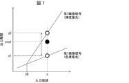
このような重み付け補間による入力値及び出力値の関係を図7に示す。図7において、x0は、第2調整部14によって用いられる高輝度条件を表している。つまり、この場合、高輝度条件は、階調値がx0以上であることである。図7に示すように、入力値(入力される調整画像信号の階調)がx0より低い場合には、重み付け補間部15から、第1調整部13により調整された第1画像信号が出力される。これは、入力値がx0より低い場合には、第2調整部14からも、第1のゲインと同一の第2のゲインを用いて調整した第1画像信号が出力されるからである。また、入力値がx0より高い場合には、第1画像信号及び第2画像信号の間で重み付け補間された出力値が、重み付け補間部15から出力される。
例えば、重み付け係数算出部151が用いる関数fは、線形関数であってもよいし、非線形関数であってもよい。代表的な線形関数fの例は、WL=Lである。また、非線形関数fの一例を、図8に示す。図8において、非線形関数fは、バックライト係数Lがより大きい範囲(高輝度領域)では、WLが1により近くなるように定められ、より小さい領域では、WLが0により近くなるように定められている。このような線形関数fまたは非線形関数fを用いて算出された重み付け係数WLを用いることにより、重み付け補間部15は、バックライトがより明るい領域ほど、輝度優先の第2画像信号により近い画像信号を出力することになる。また、重み付け補間部15は、バックライトがより暗い領域ほど、色度優先の第1画像信号により近い画像信号を出力することになる。
(テレビ1が実行する処理)
図9は、実施形態1に係るテレビ1が実行する処理の流れを示すフローチャートである。テレビ1が実行する処理について、図9を用いて説明する。
図9は、実施形態1に係るテレビ1が実行する処理の流れを示すフローチャートである。テレビ1が実行する処理について、図9を用いて説明する。
(ステップS1)
画像信号取得部10は、画像信号を取得する。画像信号取得部10は、取得した画像信号をローカルディミング制御部12に出力する。
画像信号取得部10は、画像信号を取得する。画像信号取得部10は、取得した画像信号をローカルディミング制御部12に出力する。
(ステップS2)
ローカルディミング制御部12は、ステップS1で取得された画像信号に基づいて、バックライトの各発光ブロックの点灯率を算出する。また、ローカルディミング制御部12は、算出した点灯率に基づいて、画像信号の局所領域毎の階調を調整した調整画像信号(R,G,B)を出力する。
ローカルディミング制御部12は、ステップS1で取得された画像信号に基づいて、バックライトの各発光ブロックの点灯率を算出する。また、ローカルディミング制御部12は、算出した点灯率に基づいて、画像信号の局所領域毎の階調を調整した調整画像信号(R,G,B)を出力する。
(ステップS3)
画像処理装置100は、ステップS2で算出された点灯率に基づくバックライト係数Lと、調整画像信号(R,G,B)とを入力として、ホワイトバランスを調整して画像信号を出力する。このステップの詳細については後述する。
画像処理装置100は、ステップS2で算出された点灯率に基づくバックライト係数Lと、調整画像信号(R,G,B)とを入力として、ホワイトバランスを調整して画像信号を出力する。このステップの詳細については後述する。
(ステップS4)
表示部11は、ステップS2で算出された点灯率に基づきバックライトの各発光ブロックを発光させる。また、ステップS3でホワイトバランスが調整された画像信号を、画面に表示する。
表示部11は、ステップS2で算出された点灯率に基づきバックライトの各発光ブロックを発光させる。また、ステップS3でホワイトバランスが調整された画像信号を、画面に表示する。
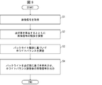
次に、ステップS3における画像処理装置100の処理の詳細について説明する。図10は、実施形態1における画像処理装置100が実行する処理の流れを示すフローチャートである。
(ステップS301)
第1調整部13は、ステップS2で出力される調整画像信号(R,G,B)に対して、第1のゲインを用いてホワイトバランスを調整した色度優先の第1画像信号(R1,G1,B1)を生成する。
第1調整部13は、ステップS2で出力される調整画像信号(R,G,B)に対して、第1のゲインを用いてホワイトバランスを調整した色度優先の第1画像信号(R1,G1,B1)を生成する。
(ステップS302)
第2調整部14は、ステップS2で出力される調整画像信号(R,G,B)に対して、第2のゲインを用いてホワイトバランスを調整した輝度優先の第2画像信号(R2,G2,B2)を生成する。
第2調整部14は、ステップS2で出力される調整画像信号(R,G,B)に対して、第2のゲインを用いてホワイトバランスを調整した輝度優先の第2画像信号(R2,G2,B2)を生成する。
(ステップS303)
重み付け係数算出部151は、ステップS2で算出された点灯率に対応するバックライト係数Lに基づいて、重み付け係数WLを算出する。
重み付け係数算出部151は、ステップS2で算出された点灯率に対応するバックライト係数Lに基づいて、重み付け係数WLを算出する。
(ステップS304)
重み付け部5は、重み付け係数WLを用いて、第1画像信号(R1,G1,B1)および第2画像信号(R2,G2,B2)に対して重み付け補間を行うことにより、画像信号(R_out1,G_out1,B_out1)を生成して出力する。
重み付け部5は、重み付け係数WLを用いて、第1画像信号(R1,G1,B1)および第2画像信号(R2,G2,B2)に対して重み付け補間を行うことにより、画像信号(R_out1,G_out1,B_out1)を生成して出力する。
以上説明したように、本実施形態に係るテレビ1は、ローカルディミング制御後の画像に対して、より適切にホワイトバランスを調整することができる。
その理由について説明する。本実施形態では、第1調整部13が、ローカルディミング制御後の調整画像信号に対して、第1のゲインを用いてホワイトバランスを調整した第1画像信号を生成する。また、第2調整部14が、調整画像信号が高輝度条件を満たす場合に、第2のゲインを用いてホワイトバランスを調整した第2画像信号を生成する。第2のゲインは、第1のゲインのうち少なくとも何れかの原色信号に対するゲインをより高い値に変更した値に設定されている。これにより、第1画像信号は、第2画像信号に比べて、色度優先の画像となる。また、第2画像信号は、第1画像信号に比べて、輝度優先の画像となる。そして、重み付け補間部15が、色度優先の第1画像信号および輝度優先の第2画像信号に対して、ローカルディミング制御により決定されたバックライト階調に基づいて重み付け補間した画像信号を出力するからである。
このように、本実施形態は、バックライトが暗くなるようローカルディミング制御された局所領域では、調整画像信号の階調値が高くても、色度優先の画像を表示することになる。このため、本実施形態は、ローカルディミング制御後の画像に対して、ホワイトバランスの調整による色味の不自然な変化を低減する。
なお、本実施形態において、重み付け補間部15が、バックライト係数Lから重み付け係数WLを算出する関数fとして、線形関数WL=Lまたは図8に示す非線形関数を用いる例について説明した。ただし、重み付け補間部15が用いる関数fは、これらに限定されない。
また、本実施形態において、重み付け補間部15は、式(2)を用いて重み付け補間を行う例について説明した。ただし、重み付け補間部15が行う重み付け補間の処理は、式(2)に基づく処理に限定されない。例えば、重み付け補間部15は、「R_out1=R1+dR×WL」との式を用いて、重み付け補間を行ってもよい。ここで、dRは、最大階調値の入力値Rに対する第1画像信号R1および第2画像信号R2の差分を表す。その他、重み付け補間部15は、テーブル参照、各種の算術演算、任意の線形補間、または、これらの組み合わせを用いて、重み付け補間を行ってもよい。
また、本実施形態において、第2調整部14が用いる高輝度条件として、調整画像信号の階調値に基づく条件を用いる例について説明した。これに限らず、高輝度条件は、調整画像信号の輝度に基づく条件であってもよい。例えば、第2調整部は、調整画像信号の各原色信号の輝度が閾値以上である場合に、第2のゲインを用いてホワイトバランスを調整した第2画像信号を生成してもよい。
また、本実施形態において、高輝度条件は、R、G、Bの各原色信号について個別に定められていてもよい。
また、本実施形態において、第2調整部14が、第2のゲインを、演算やテーブル参照により求める例について説明した。これに限らず、第2調整部14は、第1のゲインに対する第2のゲインの差分情報を記憶しておき、第1のゲイン及び差分情報に基づいて、第2のゲインを求めてもよい。これにより、第2のゲインを求めるために記憶しておくべき情報の容量が削減される。
〔実施形態2〕
本発明の他の実施形態について、以下に説明する。なお、説明の便宜上、上記実施形態にて説明した部材と同じ機能を有する部材については、同じ符号を付記し、その説明を省略する。本実施形態では、重み付け補間部が行う重み付け補間を、バックライト階調に基づくことに加えて、調整画像信号の彩度に基づいて行う例について説明する。
本発明の他の実施形態について、以下に説明する。なお、説明の便宜上、上記実施形態にて説明した部材と同じ機能を有する部材については、同じ符号を付記し、その説明を省略する。本実施形態では、重み付け補間部が行う重み付け補間を、バックライト階調に基づくことに加えて、調整画像信号の彩度に基づいて行う例について説明する。
(テレビ2の構成)
本実施形態に係るテレビ(表示装置)2は、図11に示すように、図1に示した実施形態1に係るテレビ1の構成に対して、重み付け補間部15に替えて重み付け補間部25を含む点が異なる。なお、第1調整部13、第2調整部14および、重み付け補間部25は、画像処理装置200を構成する。
本実施形態に係るテレビ(表示装置)2は、図11に示すように、図1に示した実施形態1に係るテレビ1の構成に対して、重み付け補間部15に替えて重み付け補間部25を含む点が異なる。なお、第1調整部13、第2調整部14および、重み付け補間部25は、画像処理装置200を構成する。
(重み付け補間部25の詳細)
重み付け補間部25は、第1画像信号(R1,G1,B1)及び第2画像信号(R2,G2,B2)に対して、ローカルディミング制御によるバックライト階調と、調整画像信号(R,G,B)の彩度とに基づき重み付け補間を行う。また、重み付け補間部25は、重み付け補間を行った結果得られる画像信号(R_out2,G_out2,B_out2)を出力する。
重み付け補間部25は、第1画像信号(R1,G1,B1)及び第2画像信号(R2,G2,B2)に対して、ローカルディミング制御によるバックライト階調と、調整画像信号(R,G,B)の彩度とに基づき重み付け補間を行う。また、重み付け補間部25は、重み付け補間を行った結果得られる画像信号(R_out2,G_out2,B_out2)を出力する。
例えば、重み付け補間部25は、図12に示す機能ブロックによって構成可能である。図12に示すように、重み付け補間部25は、第1重み付け係数算出部251と、第2重み付け係数算出部253と、重み付け部252と、を含む。
第1重み付け係数算出部251は、実施形態1における重み付け係数算出部151と同様に構成される。すなわち、第1重み付け係数算出部251は、ローカルディミング制御部12から出力されるバックライト係数Lに基づいて、重み付け係数WLを算出する。
第2重み付け係数算出部253は、調整画像信号の彩度に基づいて、重み付け係数WSを算出する。重み付け係数WSは、次式(3)によって算出される。
WS=fS(S)・・・(3)
ここで、関数fSは、彩度がより低いほどより大きい値を算出する関数である。また、Sは、調整画像信号(R,B,G)の彩度を表し、例えば、S=MIN(R,G,B)/MAX(R,G,B)によって算出される。なお、MIN(R,G,B)は、R,G,Bのうち最小値を表す。また、MAX(R,G,B)は、R,G,Bのうち最大値を表す。
WS=fS(S)・・・(3)
ここで、関数fSは、彩度がより低いほどより大きい値を算出する関数である。また、Sは、調整画像信号(R,B,G)の彩度を表し、例えば、S=MIN(R,G,B)/MAX(R,G,B)によって算出される。なお、MIN(R,G,B)は、R,G,Bのうち最小値を表す。また、MAX(R,G,B)は、R,G,Bのうち最大値を表す。
重み付け部252は、重み付け係数WLおよび重み付け係数WSを用いて、第1画像信号(R1,G1,B1)及び第2画像信号(R2,G2,B2)に対して重み付け補間を行う。重み付け補間によって用いられる重み付け係数Wは、次式(4)によって求められる。
W=WL×WS・・・(4)
また、重み付け補間は、例えば、赤(R)の原色信号に対して、次式(5)によって行われる。
R_out1=R1×(1-W)+R2×W・・・(5)
なお、緑(G)および青(B)の各原色信号に対しても、式(5)における文字RをGまたはBに置き換えた式が適用可能である。
W=WL×WS・・・(4)
また、重み付け補間は、例えば、赤(R)の原色信号に対して、次式(5)によって行われる。
R_out1=R1×(1-W)+R2×W・・・(5)
なお、緑(G)および青(B)の各原色信号に対しても、式(5)における文字RをGまたはBに置き換えた式が適用可能である。
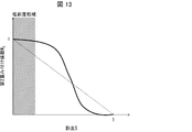
例えば、第2重み付け係数算出部253が用いる関数fSは、線形関数であってもよいし、非線形関数であってもよい。代表的な線形関数fSの例は、WS=1-Sである。また、非線形関数fSの一例を、図13に示す。図13において、非線形関数fSは、彩度Sがより小さい範囲(低彩度領域)では、WSが1により近くなるように定められ、より大きい範囲では、WSが0により近くなるように定められている。このような彩度に基づく重み付け係数WSを用いることにより、重み付け補間部25は、彩度がより低い領域ほど、輝度優先の第2画像信号により近い画像信号を出力することになる。また、重み付け補間部25は、彩度がより高い領域ほど、色度優先の第1画像信号により近い画像信号を出力することになる。換言すると、例えば、重み付け補間部25は、バックライトが比較的暗い領域であっても彩度がある程度低ければ、実施形態1よりも輝度優先の第2画像信号に近い画像信号を出力することになる。また、重み付け補間部25は、バックライトが比較的明るい領域であっても彩度がある程度高ければ、実施形態1よりも色度優先の第1画像信号に近い画像信号を出力することになる。
(テレビ2が実行する処理)
次に、実施形態2に係るテレビ2が実行する処理の流れについて説明する。テレビ2が実行する処理の概要については、図9に示して説明した実施形態1とほぼ同様であるため、説明を省略する。実施形態2では、ステップS3における処理の詳細が異なる。図14は、実施形態2における画像処理装置200が実行する処理の流れを示すフローチャートである。
次に、実施形態2に係るテレビ2が実行する処理の流れについて説明する。テレビ2が実行する処理の概要については、図9に示して説明した実施形態1とほぼ同様であるため、説明を省略する。実施形態2では、ステップS3における処理の詳細が異なる。図14は、実施形態2における画像処理装置200が実行する処理の流れを示すフローチャートである。
画像処理装置200は、ステップS301~S302まで、実施形態1における画像処理装置100と同様に動作する。これにより、色度優先の第1画像信号(R1,G1,B1)および輝度優先の第2画像信号(R2,G2,B2)が生成される。
(ステップS323)
第1重み付け係数算出部251は、ステップS2で算出された点灯率に対応するバックライト係数Lに基づいて、重み付け係数WLを算出する。
第1重み付け係数算出部251は、ステップS2で算出された点灯率に対応するバックライト係数Lに基づいて、重み付け係数WLを算出する。
(ステップS324)
第2重み付け係数算出部253は、ステップS2で出力される調整画像信号(R,G,B)から彩度Sを算出し、算出した彩度Sに基づいて、重み付け係数WSを算出する。
第2重み付け係数算出部253は、ステップS2で出力される調整画像信号(R,G,B)から彩度Sを算出し、算出した彩度Sに基づいて、重み付け係数WSを算出する。
(ステップS325)
重み付け補間部15は、重み付け係数WLおよび重み付け係数WSに基づき得られる重み付け係数Wを用いて、第1画像信号(R1,G1,B1)および第2画像信号(R2,G2,B2)に重み付け補間を行う。そして、重み付け補間部15は、重み付け補間により得られた画像信号(R_out2,G_out2,B_out2)を出力する。
重み付け補間部15は、重み付け係数WLおよび重み付け係数WSに基づき得られる重み付け係数Wを用いて、第1画像信号(R1,G1,B1)および第2画像信号(R2,G2,B2)に重み付け補間を行う。そして、重み付け補間部15は、重み付け補間により得られた画像信号(R_out2,G_out2,B_out2)を出力する。
以上説明したように、本実施形態に係るテレビ2は、ローカルディミング制御後の画像に対して、よりいっそう適切にホワイトバランスを調整することができる。
その理由について説明する。本実施形態では、重み付け補間部25が、色度優先の第1画像信号および輝度優先の第2画像信号に対して、ローカルディミング制御により決定されたバックライト階調に基づくことに加えて、彩度に基づいて重み付け補間した画像信号を出力するからである。
このように、本実施形態は、特に白色系の画像信号(すなわち、低彩度の画像信号)を対象として、バックライト階調を考慮したホワイトバランスを調整する。これにより、本実施形態は、ローカルディミング制御後の画像に対して、ホワイトバランスの調整による色味の不自然な変化をよりいっそう低減する。
〔実施形態3〕
本発明のさらに他の実施形態について、以下に説明する。なお、説明の便宜上、前記実施形態にて説明した部材と同じ機能を有する部材については、同じ符号を付記し、その説明を省略する。実施形態3では、ホワイトバランスの調整に関わる各種のパラメータをユーザが設定する構成について説明する。
本発明のさらに他の実施形態について、以下に説明する。なお、説明の便宜上、前記実施形態にて説明した部材と同じ機能を有する部材については、同じ符号を付記し、その説明を省略する。実施形態3では、ホワイトバランスの調整に関わる各種のパラメータをユーザが設定する構成について説明する。
(テレビ3の構成および処理)
本実施形態に係るテレビ(表示装置)3は、図15に示すように、図1に示した実施形態1に係るテレビ1の構成に対して、第1調整部13に替えて第1調整部33と、第2調整部14に替えて第2調整部34と、重み付け補間部15に替えて重み付け補間部35と、操作受付部17に替えて操作受付部37とを含む点が異なる。なお、第1調整部33、第2調整部34、および、重み付け補間部35は、画像処理装置300を構成する。
本実施形態に係るテレビ(表示装置)3は、図15に示すように、図1に示した実施形態1に係るテレビ1の構成に対して、第1調整部13に替えて第1調整部33と、第2調整部14に替えて第2調整部34と、重み付け補間部15に替えて重み付け補間部35と、操作受付部17に替えて操作受付部37とを含む点が異なる。なお、第1調整部33、第2調整部34、および、重み付け補間部35は、画像処理装置300を構成する。
操作受付部37は、ユーザの入力に基づく第1のゲインを取得し、記憶部16に記憶する。また、操作受付部37は、ユーザの入力に基づく高輝度条件を取得し、記憶部16に記憶する。高輝度条件として入力可能な情報は、例えば、各原色信号に対する階調の閾値であってもよい。また、操作受付部37は、輝度優先の画像のオンオフを表す情報を取得し、記憶部16に記憶する。
第1調整部33は、第1のゲインとして、ユーザの入力に基づく第1のゲインを用いる点が、実施形態1における第1調整部13に対して異なる。その他の構成については第1調整部13と同様であるため、詳細な説明を省略する。
第2調整部34は、高輝度条件として、ユーザの入力に基づく高輝度条件を用いる点が、実施形態1における第2調整部14に対して異なる。その他の構成については第2調整部14と同様であるため、詳細な説明を省略する。
重み付け補間部35は、輝度優先の画像のオンオフを表す情報がオンに設定されている場合、実施形態1における重み付け補間部15と同様に構成されて重み付け補間を行う。また、重み付け補間部35は、輝度優先の画像のオンオフを表す情報がオフに設定されている場合、重み付け補間を行わず、第1画像信号を出力する。
以上のように構成されたテレビ3が実行する処理は、図9~図10に示したフローチャートにおいて、各部がユーザ入力に基づくパラメータを用いて動作することにより説明される。
このように、本実施形態は、ローカルディミング制御後の画像に対するホワイトバランスの調整を、ユーザの好みに合わせて行うことができる。
〔ソフトウェアによる実現例〕
テレビジョン受像機1、2、3の制御ブロック(特に第1調整部13、33、第2調整部14、34および重み付け補間部15、25、35)は、集積回路(ICチップ)等に形成された論理回路(ハードウェア)によって実現してもよいし、ソフトウェアによって実現してもよい。
テレビジョン受像機1、2、3の制御ブロック(特に第1調整部13、33、第2調整部14、34および重み付け補間部15、25、35)は、集積回路(ICチップ)等に形成された論理回路(ハードウェア)によって実現してもよいし、ソフトウェアによって実現してもよい。
後者の場合、テレビジョン受像機1、2、3は、各機能を実現するソフトウェアであるプログラムの命令を実行するコンピュータを備えている。このコンピュータは、例えば少なくとも1つのプロセッサ(制御装置)を備えていると共に、上記プログラムを記憶したコンピュータ読み取り可能な少なくとも1つの記録媒体を備えている。そして、上記コンピュータにおいて、上記プロセッサが上記プログラムを上記記録媒体から読み取って実行することにより、本発明の目的が達成される。上記プロセッサとしては、例えばCPU(Central Processing Unit)を用いることができる。上記記録媒体としては、「一時的でない有形の媒体」、例えば、ROM(Read Only Memory)等の他、テープ、ディスク、カード、半導体メモリ、プログラマブルな論理回路などを用いることができる。また、上記プログラムを展開するRAM(Random Access Memory)などをさらに備えていてもよい。また、上記プログラムは、該プログラムを伝送可能な任意の伝送媒体(通信ネットワークや放送波等)を介して上記コンピュータに供給されてもよい。なお、本発明の一態様は、上記プログラムが電子的な伝送によって具現化された、搬送波に埋め込まれたデータ信号の形態でも実現され得る。
〔まとめ〕
本発明の態様1に係る画像処理装置(100)は、ホワイトバランスを調整する画像処理装置であって、バックライトのローカルディミング制御に伴い階調が調整された調整画像信号における各原色信号(R,G,B)に対して、第1のゲインを用いてホワイトバランスを調整した第1画像信号(R1,G1,B1)を生成する第1調整部(13)と、上記調整画像信号における各原色信号に対して、上記第1のゲインのうち少なくとも何れかの原色信号に対するゲインをより高い値に変更した第2のゲインを用いて、ホワイトバランスを調整した第2画像信号(R2,G2,B2)を生成する第2調整部(14)と、上記第1画像信号(R1,G1,B1)及び上記第2画像信号(R2,G2,B2)に対して、上記ローカルディミング制御によるバックライト階調に基づき重み付け補間を行った画像信号(R_out1,G_out1,B_out1)を出力する重み付け補間部(15)と、を備える。
本発明の態様1に係る画像処理装置(100)は、ホワイトバランスを調整する画像処理装置であって、バックライトのローカルディミング制御に伴い階調が調整された調整画像信号における各原色信号(R,G,B)に対して、第1のゲインを用いてホワイトバランスを調整した第1画像信号(R1,G1,B1)を生成する第1調整部(13)と、上記調整画像信号における各原色信号に対して、上記第1のゲインのうち少なくとも何れかの原色信号に対するゲインをより高い値に変更した第2のゲインを用いて、ホワイトバランスを調整した第2画像信号(R2,G2,B2)を生成する第2調整部(14)と、上記第1画像信号(R1,G1,B1)及び上記第2画像信号(R2,G2,B2)に対して、上記ローカルディミング制御によるバックライト階調に基づき重み付け補間を行った画像信号(R_out1,G_out1,B_out1)を出力する重み付け補間部(15)と、を備える。
上記の構成によれば、本態様に係る画像処理装置は、第1調整部により生成される色度優先の第1画像信号、および、第2調整部により生成される輝度優先の第2画像信号に対して、ローカルディミング制御によるバックライト階調に応じた重み付け補間を行う。そのため、本態様に係る画像処理装置は、ローカルディミング制御後の画像に対して、バックライト階調に応じて色度優先よりまたは輝度優先よりでホワイトバランスを調整することができ、より適切な画像を出力できる。
本発明の態様2に係る画像処理装置において、上記態様1における上記重み付け補間部は、上記バックライト階調が高いほど、上記第2画像信号の重み付けを大きくしてもよい。
上記の構成によれば、本態様に係る画像処理装置は、ローカルディミング制御によりバックライトがより暗く制御された領域ほど、色度優先の第1画像信号により近い画像を表示する。そのため、本態様に係る画像処理装置は、ローカルディミング制御によって高階調に変更された局所領域であっても、バックライトが暗ければ輝度優先ではなく色度優先でホワイトバランスを調整することになり、不自然な色味の変化を抑制できる。
本発明の態様3に係る画像処理装置において、上記態様1または態様2における上記重み付け補間部は、上記バックライト階調に基づくことに加えて、上記調整画像信号の彩度に基づいて、上記重み付け補間を行ってもよい。
上記の構成によれば、本態様に係る画像処理装置は、ローカルディミング制御により決定されたバックライト階調に基づくホワイトバランスの調整を、さらに調整画像信号の彩度に基づいて行う。そのため、本態様に係る画像処理装置は、より適切な画像を出力できる。
本発明の態様4に係る画像処理装置において、上記態様3における上記重み付け補間部は、上記彩度が低いほど、上記第2画像信号の重み付けを大きくしてもよい。
上記の構成によれば、本態様に係る画像処理装置は、ローカルディミング制御により決定されたバックライト階調に基づくホワイトバランスの調整を、より低彩度な白色系の調整画像信号に対して行うことになる。そのため、本態様に係る画像処理装置は、ローカルディミング制御後の画像に対するホワイトバランスの調整において、不自然な色味の変化をさらに抑制できる。
本発明の態様5に係る画像処理装置において、上記態様1から態様4の何れかにおける上記第2調整部は、上記調整画像信号が所定の高輝度条件を満たす場合に、上記第2のゲインを用いてホワイトバランスを調整した上記第2画像信号を生成してもよい。
上記の構成によれば、本態様に係る画像処理装置は、高輝度条件を満たさない調整画像信号については色度優先の第1画像信号を出力する。また、本態様に係る画像処理装置は、高輝度条件を満たす調整画像信号については、バックライト階調に応じて色度優先よりまたは輝度優先よりでホワイトバランスを調整することができる。
本発明の態様6に係る画像処理装置において、上記態様1から態様5の何れかにおける上記第2調整部は、上記第1のゲインに対する差分情報に基づいて上記第2のゲインを算出してもよい。
上記の構成によれば、本態様に係る画像処理装置は、第2調整部で用いるために記憶しておくべき情報の容量を削減することができる。
本発明の態様7に係る画像処理装置において、上記態様1から態様6の何れかにおける上記重み付け補間部は、ユーザにより入力される情報が上記第2画像信号を適用することを表す場合、上記重み付け補間を行い、上記ユーザにより入力される情報が上記第2画像信号を適用しないことを表す場合、上記第1画像信号を出力してもよい。
上記の構成によれば、本態様に係る画像処理装置は、ユーザの好みに応じて、輝度優先よりでホワイトバランスを調整した画像を適用するか否かを決定できる。
本発明の態様8に係る画像処理装置において、上記態様1から態様7の何れかにおける上記第1調整部は、上記第1のゲインとしてユーザにより入力により情報を用いて、ホワイトバランスを調整した上記第1画像信号を生成してもよい。
上記の構成によれば、本態様に係る画像処理装置は、バックライト階調に応じて色度優先よりでホワイトバランスを調整する場合に、ユーザの好みに応じた画像を出力することができる。
本発明の態様9に係る表示装置(1)は、入力される画像信号に対して上記ローカルディミング制御を実行して上記調整画像信号を生成するローカルディミング制御部と、態様1から態様8の何れかに係る画像処理装置と、を含んでいる。
上記の構成によれば、上記態様1から態様8の何れかに係る画像処理装置と同等の効果を奏する表示装置を実現できる。
本発明の態様10に係るテレビジョン受像機(1)は、上記態様9に係る表示装置を含んでいる。
上記の構成によれば、上記態様9の表示装置と同等の効果を奏するテレビジョン受像機を実現できる。
本発明の態様11に係る画像処理方法は、ホワイトバランスを調整する画像処理方法であって、バックライトのローカルディミング制御に伴い階調が調整された調整画像信号における各原色信号に対して、第1のゲインを用いてホワイトバランスを調整した第1画像信号を生成する第1調整ステップと、上記調整画像信号における各原色信号に対して、上記第1のゲインのうち、少なくとも何れかの原色信号に対するゲインをより高い値に変更した第2のゲインを用いて、ホワイトバランスを調整した第2画像信号を生成する第2調整ステップと、上記第1画像信号及び上記第2画像信号に対して、上記ローカルディミング制御によるバックライト階調に基づき重み付け補間を行った画像信号を出力する画像信号出力ステップと、含む。
上記の構成によれば、本態様に係る画像処理方法は、上記態様1に係る画像処理装置と同等の効果を奏する。
本発明の各態様に係る画像処理装置は、コンピュータによって実現してもよい。この場合には、コンピュータを、上記画像処理装置が備える各部(ソフトウェア要素)として動作させる。このように、上記画像処理装置をコンピュータにて実現させる制御プログラム、および、当該制御プログラムを記録したコンピュータ読み取り可能な記録媒体は、本発明の範疇に入る。
本発明は上述した各実施形態に限定されるものではなく、請求項に示した範囲で種々の変更が可能であり、異なる実施形態にそれぞれ開示された技術的手段を適宜組み合わせて得られる実施形態についても本発明の技術的範囲に含まれる。さらに、各実施形態にそれぞれ開示された技術的手段を組み合わせることにより、新しい技術的特徴を形成することができる。
1、2、3 テレビジョン受像機(表示装置)
10 画像信号取得部
11 表示部
12 ローカルディミング制御部
13、33 第1調整部
14、34 第2調整部
15、25、35 重み付け補間部
16 記憶部
17、37 操作受付部
100、200、300 画像処理装置
121 点灯率算出部
122 分布特性算出部
123 画像階調調整部
151 重み付け係数算出部
251 第1重み付け係数算出部
253 第2重み付け係数算出部
10 画像信号取得部
11 表示部
12 ローカルディミング制御部
13、33 第1調整部
14、34 第2調整部
15、25、35 重み付け補間部
16 記憶部
17、37 操作受付部
100、200、300 画像処理装置
121 点灯率算出部
122 分布特性算出部
123 画像階調調整部
151 重み付け係数算出部
251 第1重み付け係数算出部
253 第2重み付け係数算出部
Claims (13)
- ホワイトバランスを調整する画像処理装置であって、
バックライトのローカルディミング制御に伴い階調が調整された調整画像信号における各原色信号に対して、第1のゲインを用いてホワイトバランスを調整した第1画像信号を生成する第1調整部と、
上記調整画像信号における各原色信号に対して、上記第1のゲインのうち少なくとも何れかの原色信号に対するゲインをより高い値に変更した第2のゲインを用いて、ホワイトバランスを調整した第2画像信号を生成する第2調整部と、
上記第1画像信号及び上記第2画像信号に対して、上記ローカルディミング制御によるバックライト階調に基づき重み付け補間を行った画像信号を出力する重み付け補間部と、を備えた画像処理装置。 - 上記重み付け補間部は、上記バックライト階調が高いほど、上記第2画像信号の重み付けを大きくする、
ことを特徴とする請求項1に記載の画像処理装置。 - 上記重み付け補間部は、上記バックライト階調に基づくことに加えて、上記調整画像信号の彩度に基づいて、上記重み付け補間を行う、
ことを特徴とする請求項1または2に記載の画像処理装置。 - 上記重み付け補間部は、上記彩度が低いほど、上記第2画像信号の重み付けを大きくする、
ことを特徴とする請求項3に記載の画像処理装置。 - 上記第2調整部は、上記調整画像信号が所定の高輝度条件を満たす場合に、上記第2のゲインを用いてホワイトバランスを調整した上記第2画像信号を生成する、
ことを特徴とする請求項1から4の何れか1項に記載の画像処理装置。 - 上記第2調整部は、上記第1のゲインに対する差分情報に基づいて上記第2のゲインを算出する、
ことを特徴とする請求項1から5の何れか1項に記載の画像処理装置。 - 上記重み付け補間部は、ユーザにより入力される情報が上記第2画像信号を適用することを表す場合、上記重み付け補間を行い、上記ユーザにより入力される情報が上記第2画像信号を適用しないことを表す場合、上記第1画像信号を出力する、
ことを特徴とする請求項1から6の何れか1項に記載の画像処理装置。 - 上記第1調整部は、上記第1のゲインとしてユーザにより入力される情報を用いて、ホワイトバランスを調整した上記第1画像信号を生成する、
ことを特徴とする請求項1から7の何れか1項に記載の画像処理装置。 - 入力される画像信号に対して上記ローカルディミング制御を実行して上記調整画像信号を生成するローカルディミング制御部と、
請求項1から8の何れか1項に記載の画像処理装置と、
を含む表示装置。 - 請求項9に記載の表示装置を備えていることを特徴とするテレビジョン受像機。
- ホワイトバランスを調整する画像処理方法であって、
バックライトのローカルディミング制御に伴い階調が調整された調整画像信号における各原色信号に対して、第1のゲインを用いてホワイトバランスを調整した第1画像信号を生成する第1調整ステップと、
上記調整画像信号における各原色信号に対して、上記第1のゲインのうち、少なくとも何れかの原色信号に対するゲインをより高い値に変更した第2のゲインを用いて、ホワイトバランスを調整した第2画像信号を生成する第2調整ステップと、
上記第1画像信号及び上記第2画像信号に対して、上記ローカルディミング制御によるバックライト階調に基づき重み付け補間を行った画像信号を出力する画像信号出力ステップと、
を含む画像処理方法。 - 請求項1に記載の画像処理装置としてコンピュータを機能させるための制御プログラムであって、上記第1調整部、上記第2調整部および上記重み付け補間部としてコンピュータを機能させるための制御プログラム。
- 請求項12に記載の制御プログラムを記録したコンピュータ読み取り可能な記録媒体。
Applications Claiming Priority (2)
| Application Number | Priority Date | Filing Date | Title |
|---|---|---|---|
| JP2017-173512 | 2017-09-08 | ||
| JP2017173512A JP6545763B2 (ja) | 2017-09-08 | 2017-09-08 | 画像処理装置、テレビジョン受像機、画像処理方法、制御プログラム、および記録媒体 |
Publications (1)
| Publication Number | Publication Date |
|---|---|
| WO2019049534A1 true WO2019049534A1 (ja) | 2019-03-14 |
Family
ID=65633811
Family Applications (1)
| Application Number | Title | Priority Date | Filing Date |
|---|---|---|---|
| PCT/JP2018/027556 Ceased WO2019049534A1 (ja) | 2017-09-08 | 2018-07-23 | 画像処理装置、テレビジョン受像機、画像処理方法、制御プログラム、および記録媒体 |
Country Status (2)
| Country | Link |
|---|---|
| JP (1) | JP6545763B2 (ja) |
| WO (1) | WO2019049534A1 (ja) |
Cited By (1)
| Publication number | Priority date | Publication date | Assignee | Title |
|---|---|---|---|---|
| CN112785515A (zh) * | 2020-12-30 | 2021-05-11 | 深圳Tcl数字技术有限公司 | 局部调光控制方法、装置、设备及存储介质 |
Citations (7)
| Publication number | Priority date | Publication date | Assignee | Title |
|---|---|---|---|---|
| WO2011004520A1 (ja) * | 2009-07-06 | 2011-01-13 | シャープ株式会社 | 液晶表示装置、及び液晶表示装置の表示制御方法 |
| JP2011250306A (ja) * | 2010-05-28 | 2011-12-08 | Toshiba Corp | 映像信号処理装置及び映像信号処理方法 |
| JP2012044608A (ja) * | 2010-08-23 | 2012-03-01 | Mitsumi Electric Co Ltd | 輝度制御装置及び輝度制御方法 |
| JP2013015630A (ja) * | 2011-07-01 | 2013-01-24 | Hitachi Consumer Electronics Co Ltd | 映像表示装置、映像表示方法及び映像処理装置 |
| JP2013092642A (ja) * | 2011-10-26 | 2013-05-16 | Sharp Corp | 液晶表示装置 |
| WO2013141071A1 (ja) * | 2012-03-22 | 2013-09-26 | 富士フイルム株式会社 | 画像表示装置及び方法 |
| WO2016111362A1 (ja) * | 2015-01-09 | 2016-07-14 | シャープ株式会社 | 液晶表示装置、液晶表示装置の制御方法 |
-
2017
- 2017-09-08 JP JP2017173512A patent/JP6545763B2/ja not_active Expired - Fee Related
-
2018
- 2018-07-23 WO PCT/JP2018/027556 patent/WO2019049534A1/ja not_active Ceased
Patent Citations (7)
| Publication number | Priority date | Publication date | Assignee | Title |
|---|---|---|---|---|
| WO2011004520A1 (ja) * | 2009-07-06 | 2011-01-13 | シャープ株式会社 | 液晶表示装置、及び液晶表示装置の表示制御方法 |
| JP2011250306A (ja) * | 2010-05-28 | 2011-12-08 | Toshiba Corp | 映像信号処理装置及び映像信号処理方法 |
| JP2012044608A (ja) * | 2010-08-23 | 2012-03-01 | Mitsumi Electric Co Ltd | 輝度制御装置及び輝度制御方法 |
| JP2013015630A (ja) * | 2011-07-01 | 2013-01-24 | Hitachi Consumer Electronics Co Ltd | 映像表示装置、映像表示方法及び映像処理装置 |
| JP2013092642A (ja) * | 2011-10-26 | 2013-05-16 | Sharp Corp | 液晶表示装置 |
| WO2013141071A1 (ja) * | 2012-03-22 | 2013-09-26 | 富士フイルム株式会社 | 画像表示装置及び方法 |
| WO2016111362A1 (ja) * | 2015-01-09 | 2016-07-14 | シャープ株式会社 | 液晶表示装置、液晶表示装置の制御方法 |
Cited By (1)
| Publication number | Priority date | Publication date | Assignee | Title |
|---|---|---|---|---|
| CN112785515A (zh) * | 2020-12-30 | 2021-05-11 | 深圳Tcl数字技术有限公司 | 局部调光控制方法、装置、设备及存储介质 |
Also Published As
| Publication number | Publication date |
|---|---|
| JP6545763B2 (ja) | 2019-07-17 |
| JP2019049637A (ja) | 2019-03-28 |
Similar Documents
| Publication | Publication Date | Title |
|---|---|---|
| US10761371B2 (en) | Display device | |
| JP5124050B1 (ja) | 映像表示装置およびテレビ受信装置 | |
| JP6350980B2 (ja) | 制御回路及び当該制御回路を備えた表示装置 | |
| US9654701B2 (en) | Global display management based light modulation | |
| JP6086393B2 (ja) | 制御信号生成回路,映像表示装置,制御信号生成方法,及びそのプログラム | |
| US10347198B2 (en) | Image displaying methods and display devices | |
| JP2007163647A (ja) | 画像表示装置 | |
| JP2007537645A (ja) | カラー画像データの処理方法 | |
| JPWO2012137819A1 (ja) | 表示装置、及び表示方法 | |
| US11024255B2 (en) | Method and apparatus for color calibration for reduced motion-induced color breakup | |
| JP4950846B2 (ja) | カラー画像表示装置及び色変換装置 | |
| US20110096249A1 (en) | Method for processing video data for a liquid crystal display | |
| CN108886609B (zh) | 显示装置、电视接收机、显示方法、控制程序及记录介质 | |
| JP2011242665A (ja) | 画像表示装置 | |
| JP6190482B1 (ja) | 表示制御装置、表示装置、テレビジョン受像機、表示制御装置の制御方法、制御プログラム、及び記録媒体 | |
| JPWO2017126309A1 (ja) | 表示装置、表示方法、制御プログラム、記録媒体、およびテレビジョン受像機 | |
| CN115176469A (zh) | 用于饱和颜色的改进的hdr颜色处理 | |
| JP6545763B2 (ja) | 画像処理装置、テレビジョン受像機、画像処理方法、制御プログラム、および記録媒体 | |
| US8284317B2 (en) | Device and method for color adjustment | |
| CN109427313B (zh) | 显示设备、显示控制方法及计算机可读介质 | |
| JP7324151B2 (ja) | 表示装置 | |
| JP2015111195A (ja) | 映像情報表示装置 | |
| KR20190066110A (ko) | 영상 처리부, 그것을 포함하는 표시 장치, 및 영상 처리 방법 | |
| WO2017163685A1 (ja) | 映像処理装置、表示装置、映像処理方法、制御プログラム、および記録媒体 | |
| JP5203344B2 (ja) | 制御装置およびその制御方法、制御装置に用いられる表示制御装置、電子機器、制御プログラム、並びに該プログラムを記録した記録媒体 |
Legal Events
| Date | Code | Title | Description |
|---|---|---|---|
| 121 | Ep: the epo has been informed by wipo that ep was designated in this application |
Ref document number: 18854090 Country of ref document: EP Kind code of ref document: A1 |
|
| NENP | Non-entry into the national phase |
Ref country code: DE |
|
| 122 | Ep: pct application non-entry in european phase |
Ref document number: 18854090 Country of ref document: EP Kind code of ref document: A1 |