WO2019049372A1 - 変倍光学系、光学装置、および変倍光学系の製造方法 - Google Patents
変倍光学系、光学装置、および変倍光学系の製造方法 Download PDFInfo
- Publication number
- WO2019049372A1 WO2019049372A1 PCT/JP2017/032695 JP2017032695W WO2019049372A1 WO 2019049372 A1 WO2019049372 A1 WO 2019049372A1 JP 2017032695 W JP2017032695 W JP 2017032695W WO 2019049372 A1 WO2019049372 A1 WO 2019049372A1
- Authority
- WO
- WIPO (PCT)
- Prior art keywords
- lens group
- lens
- optical system
- variable magnification
- magnification optical
- Prior art date
- Legal status (The legal status is an assumption and is not a legal conclusion. Google has not performed a legal analysis and makes no representation as to the accuracy of the status listed.)
- Ceased
Links
Images









Classifications
-
- G—PHYSICS
- G02—OPTICS
- G02B—OPTICAL ELEMENTS, SYSTEMS OR APPARATUS
- G02B13/00—Optical objectives specially designed for the purposes specified below
- G02B13/18—Optical objectives specially designed for the purposes specified below with lenses having one or more non-spherical faces, e.g. for reducing geometrical aberration
-
- G—PHYSICS
- G02—OPTICS
- G02B—OPTICAL ELEMENTS, SYSTEMS OR APPARATUS
- G02B15/00—Optical objectives with means for varying the magnification
- G02B15/14—Optical objectives with means for varying the magnification by axial movement of one or more lenses or groups of lenses relative to the image plane for continuously varying the equivalent focal length of the objective
- G02B15/16—Optical objectives with means for varying the magnification by axial movement of one or more lenses or groups of lenses relative to the image plane for continuously varying the equivalent focal length of the objective with interdependent non-linearly related movements between one lens or lens group, and another lens or lens group
- G02B15/20—Optical objectives with means for varying the magnification by axial movement of one or more lenses or groups of lenses relative to the image plane for continuously varying the equivalent focal length of the objective with interdependent non-linearly related movements between one lens or lens group, and another lens or lens group having an additional movable lens or lens group for varying the objective focal length
Definitions
- the present invention relates to a variable magnification optical system, an optical device, and a method of manufacturing the variable magnification optical system.
- variable magnification optical system capable of high-speed focusing suitable for moving image shooting while being compact and compatible with a large image pickup element.
- JP-A-2015-064492 Japanese Patent Application Laid-A-2015-064492.
- correction of various aberrations has not been sufficient.
- the present invention From the object side, in order from the object side, a first lens group having a positive refractive power, a second lens group having a negative refractive power, a third lens group having a positive refractive power, and a subsequent lens group having a positive refractive power Have and At the time of zooming, the distance between the first lens group and the second lens group changes, the distance between the second lens group and the third lens group changes, and the third lens group and the subsequent lens group And the distance between The subsequent lens unit has a focusing lens unit which moves at the time of focusing; It is a variable power optical system that satisfies the following conditional expression.
- ⁇ Fw lateral magnification of the focusing lens group in the wide-angle end state
- BFw back focus of the variable magnification optical system in the wide angle end state
- fw focal length of the variable magnification optical system in the wide angle end state
- the present invention is From the object side, in order from the object side, a first lens group having a positive refractive power, a second lens group having a negative refractive power, a third lens group having a positive refractive power, and a subsequent lens group having a positive refractive power
- a variable magnification optical system having At the time of zooming, the distance between the first lens group and the second lens group changes, the distance between the second lens group and the third lens group changes, and the third lens group and the subsequent lens group Configured to change the distance between The subsequent lens unit is configured to have a focusing lens unit that moves at the time of focusing; This is a manufacturing method of a variable magnification optical system configured to satisfy the following conditional expression.
- ⁇ Fw lateral magnification of the focusing lens group in the wide-angle end state
- BFw back focus of the variable magnification optical system in the wide angle end state
- fw focal length of the variable magnification optical system in the wide angle end state
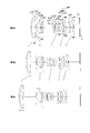
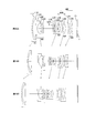
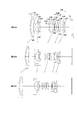
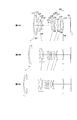
- FIG. 1A, FIG. 1B, and FIG. 1C are cross-sectional views in the wide-angle end state, the intermediate focal length state, and the telephoto end state, respectively, of the variable magnification optical system according to the first example.
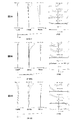
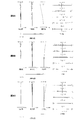
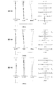
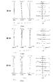
- FIGS. 2A, 2B, and 2C are aberration diagrams at the time of focusing on an infinity object in the wide-angle end state, the intermediate focal length state, and the telephoto end state of the variable magnification optical system according to the first example, respectively.
- FIGS. 3A, 3B, and 3C are various aberration diagrams at the time of focusing on a short distance object in the wide-angle end state, the intermediate focal length state, and the telephoto end state of the variable magnification optical system according to the first example.
- FIG. 1A, FIG. 1B, and FIG. 1C are cross-sectional views in the wide-angle end state, the intermediate focal length state, and the telephoto end state, respectively, of the variable magnification optical system according to the first example.
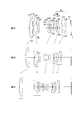
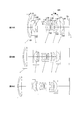
- FIGS. 4A, FIG. 4B, and FIG. 4C are cross-sectional views in the wide-angle end state, the intermediate focal length state, and the telephoto end state, respectively, of the variable magnification optical system according to the second example.
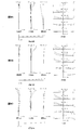
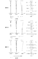
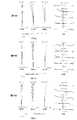
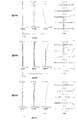
- FIGS. 5A, 5B, and 5C are aberration diagrams at the time of focusing on an infinity object in the wide-angle end state, the intermediate focal length state, and the telephoto end state of the variable magnification optical system according to the second example, respectively.
- FIGS. 6A, 6B, and 6C are various aberration diagrams at the time of focusing on a short distance object in the wide-angle end state, the intermediate focal length state, and the telephoto end state of the variable magnification optical system according to the second example.
- FIGS. 7A, 7B, and 7C are cross-sectional views of the variable magnification optical system according to the third example at the wide-angle end, at an intermediate focal length, and at the telephoto end, respectively.
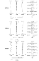
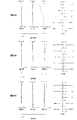
- FIGS. 8A, 8B, and 8C are aberration diagrams at the time of focusing on an infinity object in the wide-angle end state, the intermediate focal length state, and the telephoto end state of the variable magnification optical system according to the third example, respectively.
- FIGS. 9A, 9B, and 9C are various aberration diagrams at the time of focusing on a short distance object in the wide-angle end state, the intermediate focal length state, and the telephoto end state of the variable magnification optical system according to the third example.
- FIGS. 11A, 11B, and 11C are various aberration diagrams at the time of focusing on an infinity object in the wide-angle end state, the intermediate focal length state, and the telephoto end state of the variable magnification optical system according to the fourth example.
- 12A, 12B, and 12C are various aberration diagrams at the time of focusing on a short distance object in the wide-angle end state, the intermediate focal length state, and the telephoto end state of the variable magnification optical system according to the fourth example.
- FIGS. 13A, 13B, and 13C are cross-sectional views of the variable magnification optical system according to the fifth example, at the wide-angle end, at an intermediate focal length, and at the telephoto end.
- FIG. 14A, FIG. 14B, and FIG. 14C are various aberration diagrams at the time of infinity object focusing in the wide-angle end state, the intermediate focal length state, and the telephoto end state of the variable magnification optical system according to the fifth example.
- FIG. 15A, FIG. 15B, and FIG. 15C are various aberration diagrams at the time of focusing on a short distance object in the wide-angle end state, the intermediate focal length state, and the telephoto end state of the variable magnification optical system according to the fifth example.
- FIGS. 17A, 17B, and 17C are aberration diagrams at the time of focusing on an infinity object in the wide-angle end state, the intermediate focal length state, and the telephoto end state of the variable magnification optical system according to the sixth example.
- 18A, 18B, and 18C are various aberration diagrams at the time of focusing on a short distance object in the wide-angle end state, the intermediate focal length state, and the telephoto end state of the variable magnification optical system according to the sixth example.
- FIGS. 19A, 19B, and 19C are cross-sectional views of the zoom optical system according to the seventh embodiment at the wide-angle end, at an intermediate focal length, and at the telephoto end, respectively.
- FIGS. 20A, 20B, and 20C are aberration diagrams at the time of focusing on an infinity object in the wide-angle end state, the intermediate focal length state, and the telephoto end state, respectively, of the zoom optical system according to the seventh example.
- FIGS. 21A, 21B, and 21C are various aberration diagrams at the time of focusing on a short distance object in the wide-angle end state, the intermediate focal length state, and the telephoto end state of the variable magnification optical system according to the seventh example.
- FIGS. 22A, 22B, and 22C are cross-sectional views of the zoom optical system according to the eighth embodiment at the wide-angle end, at an intermediate focal length, and at the telephoto end, respectively.
- FIGS. 23A, 23B, and 23C show various aberrations of the variable magnification optical system of the eighth embodiment at the wide-angle end state, at the intermediate focal length state, and at the telephoto end state when focusing on infinity.
- FIGS. 24A, 24B, and 24C show various aberrations of the variable magnification optical system according to Example 8 at the wide-angle end, at the intermediate focal length, and at the telephoto end when focusing on short-distance objects.
- FIG. 25 is a diagram showing the configuration of a camera provided with a variable magnification optical system.
- FIG. 26 is a flowchart showing an outline of a method of manufacturing a variable magnification optical system.
- variable magnification optical system an optical device, and a method of manufacturing the variable magnification optical system according to the present embodiment will be described.
- variable magnification optical system according to the present embodiment will be described.
- the variable magnification optical system includes, in order from the object side, a first lens group having positive refractive power, a second lens group having negative refractive power, and a third lens group having positive refractive power. And a rear lens group having a positive refractive power, and during zooming from the wide-angle end state to the telephoto end state, the distance between the first lens group and the second lens group changes, and the second lens group The distance between the third lens unit and the third lens unit changes, and the distance between the third lens unit and the subsequent lens unit changes, and the subsequent lens unit focuses on a near distance object from an infinite distance object. It has a moving focusing lens group, and is configured to satisfy the following conditional expressions (1) and (2).
- ⁇ Fw lateral magnification of the focusing lens group in the wide-angle end state
- BFw back focus of the variable magnification optical system in the wide angle end state
- fw focal length of the variable magnification optical system in the wide angle end state
- the subsequent lens group of the variable magnification optical system of this embodiment has at least two lens groups.
- the lens group refers to a portion having at least one lens separated by an air gap.
- the lens component refers to a single lens or a cemented lens formed by cementing two or more lenses.
- the focusing lens unit can be reduced in size and weight, and as a result, focusing can be performed at high speed, and the variable magnification optical system and the lens barrel can be miniaturized.
- Conditional expression (1) defines the lateral magnification of the focusing lens unit in the wide-angle end state.
- the variable magnification optical system according to the present embodiment can reduce the amount of movement of the focusing lens group at the time of focusing, thereby achieving downsizing of the variable magnification optical system. it can.
- conditional expression (1) of the variable magnification optical system of the present embodiment exceeds the upper limit value, the moving amount of the focusing lens unit at the time of focusing becomes large, and downsizing of the variable magnification optical system is difficult It becomes.
- conditional expression (1) of the variable magnification optical system of the present embodiment falls below the lower limit, the sensitivity becomes high and the movement amount of the focusing lens group at focusing becomes small. It will be difficult.
- Conditional expression (2) defines the ratio of the back focus of the variable magnification optical system in the wide angle end state to the focal length of the variable magnification optical system in the wide angle end state.
- conditional expression (2) of the variable magnification optical system of the present embodiment exceeds the upper limit value, the back focus of the variable magnification optical system in the wide angle end state with respect to the focal length of the variable magnification optical system in the wide angle end state. Becomes large, and it becomes difficult to satisfactorily correct various aberrations in the wide-angle end state.
- variable magnification optical system in the wide angle end state with respect to the focal length of the variable magnification optical system in the wide angle end state.
- the back focus decreases, and it becomes difficult to satisfactorily correct various aberrations in the wide-angle end state, particularly coma.
- conditional expression (2) “back focus of the variable magnification optical system in the wide angle end state” indicated by BFw is “back focus of the variable magnification optical system in the state where the total length is shortest”.
- the focal length of the variable magnification optical system in the end state may be set as the “focal length of the variable magnification optical system in the state where the total length is the shortest”. That is, conditional expression (2) may be expressed as follows. (2) 0.100 ⁇ BFs / fs ⁇ 1.00 However, BFs: back focus of the variable magnification optical system in the shortest total length state fs: focal length of the variable magnification optical system in the shortest total length state
- variable magnification optical system can cope with a large image sensor while being small, and variable magnification optical system capable of favorably correcting various aberrations at the time of zooming and focusing. System can be realized.
- variable magnification optical system of the present embodiment has the fourth lens group in which the subsequent lens group has positive refractive power and the fifth lens group having negative refractive power, and the following conditional expression (3) It is desirable to satisfy (3)-3.000 ⁇ f5 / f3 ⁇ -0.500 However, f3: focal length of the third lens group f5: focal length of the fifth lens group
- Conditional expression (3) defines the ratio of the focal length of the third lens unit to the focal length of the fifth lens unit.
- the refractive power of the third lens unit becomes larger than the refractive power of the fifth lens unit, and various values in the wide-angle end state It becomes difficult to satisfactorily correct aberrations, in particular astigmatism.
- the refractive power of the fifth lens group becomes larger than the refractive power of the third lens group, and the telephoto end state It is difficult to satisfactorily correct various aberrations in, in particular, coma.
- variable magnification optical system of the present embodiment it is desirable that the fourth lens group has a focusing lens group.
- the variable magnification optical system according to the present embodiment can reduce the size and weight of the focusing lens unit, and as a result, the variable magnification optical system and the lens barrel can be miniaturized.
- variable magnification optical system of the present embodiment it is desirable that the following conditional expression (4) be satisfied.
- f1 focal length of the first lens group
- f1Rw combined focal length in the wide-angle end state of the lens group disposed on the image plane side of the first lens group
- Conditional expression (4) defines the ratio of the focal length of the first lens group to the combined focal length in the wide-angle end state of the lens group disposed closer to the image plane than the first lens group.
- the refractive power in the wide-angle end state of the lens unit disposed closer to the image plane than the first lens unit increases. It becomes difficult to correct various aberrations in the end state, in particular coma.
- the refractive power of the first lens group becomes large, and various aberrations in the wide-angle end state, in particular coma It becomes difficult to correct.
- variable magnification optical system of the present embodiment it is desirable that the following conditional expression (5) be satisfied.
- nd3fp the refractive index of the lens with the largest refractive index in the third lens group
- Conditional expression (5) defines the refractive index of the lens with the largest refractive power in the third lens group.
- the variable magnification optical system of the present embodiment can satisfactorily correct axial chromatic aberration and spherical aberration by using a glass material with high refractive power that satisfies the conditional expression (5).
- the refractive power of the third lens group increases, and it is difficult to satisfactorily correct axial chromatic aberration and spherical aberration. Become.
- variable magnification optical system of the present embodiment satisfy the following conditional expression (6).
- d d 3 p Abbe number of the lens with the smallest Abbe number in the third lens group
- Conditional expression (6) defines the Abbe number of the lens with the smallest Abbe number in the third lens group.
- the third lens group can have anomalous dispersion, and axial chromatic aberration and spherical aberration are excellent. Can be corrected.
- the third lens group can not have sufficient anomalous dispersion, and axial chromatic aberration and spherical aberration are excellent. It is difficult to make corrections.
- variable magnification optical system of the present embodiment it is desirable that the following conditional expression (7) be satisfied.
- (7) 0.500 ⁇ 1 / ⁇ Rw ⁇ 1.000
- ⁇ Rw Lateral magnification of the lens unit disposed closest to the image plane in the wide-angle end state
- Conditional expression (7) defines the lateral magnification of the lens unit disposed closest to the image plane in the wide-angle end state.
- the corresponding value of the conditional expression (7) of the variable magnification optical system according to the present embodiment exceeds the upper limit, the lateral magnification of the lens unit disposed closest to the image plane in the wide angle end state decreases, and various values in the wide angle end state It becomes difficult to satisfactorily correct aberrations, in particular astigmatism.
- the corresponding value of the conditional expression (7) of the variable magnification optical system of the present embodiment falls below the lower limit, the lateral magnification of the lens unit disposed closest to the image plane in the wide angle end state becomes large. Curvature of field tends to occur, and it becomes difficult to correct various aberrations well.
- variable magnification optical system of this embodiment satisfies the following conditional expression (8).
- (8) 0.500 ⁇ f2 fn / f2 ⁇ 1.100
- f2 fn focal length of the lens component closest to the object in the second lens group
- f2 focal length of the second lens group
- Conditional expression (8) defines the ratio of the focal length of the lens component closest to the object in the second lens group to the focal length of the second lens group.
- conditional expression (8) of the variable magnification optical system according to the present embodiment exceeds the upper limit, the refractive power of the lens component closest to the object in the second lens group decreases, and various aberrations including spherical aberration are caused. It becomes difficult to correct aberrations well.
- conditional expression (8) of the variable magnification optical system of the present embodiment falls below the lower limit value
- the refracting power of the lens component closest to the object in the second lens group becomes large. It becomes difficult to correct various aberrations well.
- variable magnification optical system of this embodiment satisfies the following conditional expression (9). (9) 0.300 ⁇ fF / ft ⁇ 1.400
- fF focal length of the focusing lens unit
- ft focal length of the variable magnification optical system in the telephoto end state
- Conditional expression (9) defines the ratio of the focal length of the focusing lens unit to the focal length of the variable magnification optical system in the telephoto end state.
- the variable magnification optical system according to this embodiment suppresses fluctuations of various aberrations including the spherical aberration at the time of focusing from an infinite distance object to a close distance object, and It is possible to miniaturize the magnification optical system and the lens barrel.
- the refractive power of the focusing lens unit decreases, and various items in focusing from an infinite distance object to a near distance object It becomes difficult to satisfactorily correct aberration fluctuation, particularly spherical aberration fluctuation.
- conditional expression (9) of the variable magnification optical system of the present embodiment falls below the lower limit
- the refractive power of the focusing lens unit becomes large, and focusing from an infinite distance object to a close distance object It becomes difficult to correct well the fluctuations of the various aberrations, in particular the fluctuations of the spherical aberration.
- variable magnification optical system of the present embodiment it is desirable that the following conditional expression (10) be satisfied. (10) 40.00 ° ⁇ w ⁇ 85.00 ° However, ⁇ w: half angle of view of the variable magnification optical system in the wide angle end state
- Conditional expression (10) defines a half angle of view of the variable magnification optical system in the wide-angle end state.
- the variable magnification optical system according to the present embodiment can satisfactorily correct various aberrations such as coma aberration, distortion, and curvature of field while having a wide angle of view. .
- the corresponding value of the conditional expression (10) of the variable magnification optical system according to the present embodiment exceeds the upper limit value, the angle of view becomes too wide, and various aberrations such as coma aberration, distortion, and field curvature are corrected well. Is difficult.
- the angle of view becomes narrow, and it becomes difficult to satisfactorily correct various aberrations.
- the optical device of the present embodiment has the variable magnification optical system having the above-described configuration. As a result, it is possible to realize an optical device that can cope with a large-sized image sensor while being small, and that can properly correct various aberrations at the time of zooming and focusing.
- the method of manufacturing a variable magnification optical system includes, in order from the object side, a first lens group having positive refractive power, a second lens group having negative refractive power, and a third lens group having positive refractive power.
- a manufacturing method of a variable magnification optical system having a lens group and a subsequent lens group having a positive refractive power which comprises changing the first lens group and the second lens at the time of zooming from the wide-angle end state to the telephoto end state.
- the distance between the second lens group and the third lens group changes, and the distance between the second lens group and the third lens group changes, and the distance between the third lens group and the subsequent lens group changes.
- variable power optical system configured such that the group has a focusing lens group that moves at the time of focusing from an infinite distance object to a close distance object, and satisfies the following conditional expressions (1) and (2) Manufacturing method.
- ⁇ Fw lateral magnification of the focusing lens group in the wide-angle end state
- BFw back focus of the variable magnification optical system in the wide angle end state
- fw focal length of the variable magnification optical system in the wide angle end state
- FIGS. 1A, 1B, and 1C are cross-sectional views in a wide-angle end state, an intermediate focal length state, and a telephoto end state, respectively, of a variable magnification optical system according to a first example of the present embodiment.
- Arrows under the respective lens units in FIG. 1A indicate moving directions of the respective lens units during zooming from the wide-angle end state to the intermediate focal length state.
- Arrows under the respective lens units in FIG. 1B indicate movement loci of the respective lens units during zooming from the intermediate focal length state to the telephoto end state.
- variable magnification optical system includes, in order from the object side along the optical axis, a first lens group G1 having a positive refractive power, a second lens group G2 having a negative refractive power, and an aperture stop S. And a third lens group G3 having a positive refractive power and a subsequent lens group GR having a positive refractive power.
- the first lens group G1 is composed of, in order from the object side along the optical axis, a cemented lens of a negative meniscus lens L11 having a convex surface on the object side and a positive meniscus lens L12 having a convex surface on the object side.
- the second lens group G2 includes, in order from the object side along the optical axis, a negative meniscus lens L21 having a convex surface facing the object, a negative biconcave lens L22, and a positive meniscus lens L23 having a convex surface facing the object It consists of
- the negative meniscus lens L21 is a glass mold aspheric lens in which the lens surface on the image plane I side is aspheric.
- the third lens group G3 includes, in order from the object side along the optical axis, a double convex positive lens L31, and a cemented lens of a negative meniscus lens L32 with a convex surface facing the object side and a double convex positive lens L33. And a cemented lens of a biconcave negative lens L34 and a biconvex positive lens L35.
- the biconvex positive lens L31 is a glass mold aspheric lens in which the lens surface on the object side is aspheric.
- the subsequent lens group GR includes, in order from the object side along the optical axis, a fourth lens group G4 having positive refractive power and a fifth lens group G5 having negative refractive power.
- the fourth lens group G4 is composed of, in order from the object side along the optical axis, a negative meniscus lens L41 with a concave surface facing the object side, and a biconvex positive lens L42.
- the biconvex positive lens L42 is a glass mold aspheric lens in which the lens surface on the image plane I side is aspheric.
- the fifth lens group G5 is composed of, in order from the object side along the optical axis, a positive meniscus lens L51 having a concave surface facing the object, and a biconcave negative lens L52.
- the positive meniscus lens L51 is a glass mold aspheric lens in which the lens surface on the image plane I side is aspheric.
- a filter FL such as a low pass filter is disposed between the fifth lens group G5 and the image plane I.
- an imaging device (not shown) composed of a CCD, a CMOS or the like is disposed on the image plane I.
- variable magnification optical system the distance between the first lens group G1 and the second lens group G2, the second lens group G2 and the third lens group G3 during zooming from the wide-angle end state to the telephoto end state.
- the first lens group G1 to the fifth lens group G5 such that the distance between them, the distance between the third lens group G3 and the fourth lens group G4, and the distance between the fourth lens group G4 and the fifth lens group G5 change. All lens groups up to are moved along the optical axis.
- the aperture stop S moves integrally with the third lens group G3 at the time of zooming from the wide-angle end state to the telephoto end state.
- focusing from an infinite distance object to a near distance object is performed by moving the fourth lens unit G4 as the focusing lens unit along the optical axis in the object direction.
- Table 1 below presents values of specifications of the variable magnification optical system according to the present example.
- m is the order of the optical surface counted from the object side
- r is the radius of curvature
- d is the surface distance (distance between the nth surface (n is an integer) and the n + 1th surface)
- nd is the d line
- the refractive index with respect to a wavelength of 587.6 nm) and d d respectively indicate Abbe numbers with respect to the d-line (wavelength of 587.6 nm).
- OP indicates an object plane
- Dn (n is an integer) indicates a variable surface interval
- S indicates an aperture stop
- I indicates an image plane.
- the radius of curvature r ⁇ indicates a plane.
- the description of the refractive index nd 1.00000 of air is omitted.
- the lens surface is an aspheric surface, the surface number is marked with *, and the paraxial radius of curvature is shown in the column of radius of curvature r.
- f focal length
- FNo F number
- ⁇ half angle of view (unit: “°”)
- Y maximum image height
- TL the total length of the variable power optical system according to the present embodiment, ie The distances on the optical axis from 1 plane to the image plane I are shown.
- BF indicates back focus, that is, the distance on the optical axis from the lens surface closest to the image side to the image plane I
- BF air equivalent length indicates the distance on the optical axis from the lens surface closest to the image to the image plane I
- W indicates the wide-angle end state
- M indicates the intermediate focal length state
- T indicates the telephoto end state.
- the starting surface number ST of each lens group and the focal length f are shown.
- [Spherical surface data] shows the aspheric surface coefficient and the conical constant when the shape of the aspheric surface shown in [Surface data] is expressed by the following equation.
- x (h 2 / r) / [1+ ⁇ 1-1 (h / r) 2 ⁇ 1/2 ] + A4h 4 + A6h 6 + A8h 8 + A10h 10
- h is the height in the direction perpendicular to the optical axis
- x is the distance along the optical axis direction from the tangent plane of the apex of the aspheric surface at height h to the aspheric surface
- ⁇ is the conical constant
- A4, A6, A8 and A10 are aspheric coefficients
- r is a paraxial radius of curvature which is a radius of curvature of the reference spherical surface.
- E-n (n is an integer) indicates "x 10- n ", for example, "1.234 E-05" indicates
- Dn (n is an integer) indicates the surface distance between the nth surface and the (n + 1) surface.
- W indicates the wide-angle end state
- M indicates the intermediate focal length state
- T indicates the telephoto end state
- infinity indicates the time of focusing on an infinite distance object
- short distance indicates the time of focusing on a short distance object.
- [Conditional expression corresponding value] indicates the corresponding value of each conditional expression.
- mm is generally used as the unit of focal length f and radius of curvature r described in Table 1 and other lengths.
- the optical system is not limited to this, because the same optical performance can be obtained by proportional enlargement or reduction.
- symbol of Table 1 described above shall be similarly used also in the table
- FIGS. 2A, 2B, and 2C are various aberration diagrams at the time of focusing on an infinity object in the wide-angle end state, the intermediate focal length state, and the telephoto end state of the variable magnification optical system according to the first example, respectively.
- FIGS. 3A, 3B, and 3C are various aberration diagrams at the time of focusing on a short distance object in the wide-angle end state, the intermediate focal length state, and the telephoto end state of the variable magnification optical system according to the first example.
- FNO denotes an F number
- NA denotes a numerical aperture
- A denotes a light beam incident angle, that is, a half angle of view (unit: "°")
- H0 denotes an object height (unit: mm).
- the spherical aberration diagram shows the value of the F number FNO or the numerical aperture NA corresponding to the maximum aperture
- the astigmatism diagram and the distortion diagram show the maximum value of the half angle of view or the object height respectively
- the coma diagram The value of each half angle of view or each object height is shown.
- d indicates the aberration at the d-line (wavelength 587.6 nm)
- g indicates the aberration at the g-line (wavelength 435.8 nm)
- those without d and g indicate the aberration at the d-line.
- a solid line indicates a sagittal image plane
- a broken line indicates a meridional image plane.
- the coma aberration diagram shows coma aberration, that is, lateral aberration at each half angle of view or each object height.
- the same reference numerals as in this example are used also in the aberration charts of the examples which will be described later.
- variable magnification optical system As shown in the respective aberration diagrams, the variable magnification optical system according to the present embodiment has excellent imaging performance by favorably correcting various aberrations from the wide-angle end state to the telephoto end state, and also at the time of focusing on a short distance object. It can be seen that it has excellent imaging performance.
- FIG. 4A, FIG. 4B, and FIG. 4C are cross-sectional views in the wide-angle end state, the intermediate focal length state, and the telephoto end state of the variable magnification optical system according to the second example of the present embodiment.
- Arrows under the respective lens units in FIG. 4A indicate the moving directions of the respective lens units during zooming from the wide-angle end state to the intermediate focal length state.
- Arrows under the respective lens units in FIG. 4B indicate movement loci of the respective lens units during zooming from the intermediate focal length state to the telephoto end state.
- variable magnification optical system includes, in order from the object side along the optical axis, a first lens group G1 having a positive refractive power, a second lens group G2 having a negative refractive power, and an aperture stop S. And a third lens group G3 having a positive refractive power and a subsequent lens group GR having a positive refractive power.
- the first lens group G1 is composed of, in order from the object side along the optical axis, a cemented lens of a negative meniscus lens L11 having a convex surface on the object side and a positive meniscus lens L12 having a convex surface on the object side.
- the second lens group G2 includes, in order from the object side along the optical axis, a negative meniscus lens L21 having a convex surface facing the object, a negative biconcave lens L22, and a positive meniscus lens L23 having a convex surface facing the object It consists of
- the negative meniscus lens L21 is a glass mold aspheric lens in which the lens surface on the image plane I side is aspheric.
- the third lens group G3 includes, in order from the object side along the optical axis, a double convex positive lens L31, and a cemented lens of a negative meniscus lens L32 with a convex surface facing the object side and a double convex positive lens L33. And a cemented lens of a biconcave negative lens L34 and a biconvex positive lens L35.
- the biconvex positive lens L31 is a glass mold aspheric lens in which the lens surface on the object side is aspheric.
- the subsequent lens group GR includes, in order from the object side along the optical axis, a fourth lens group G4 having positive refractive power and a fifth lens group G5 having negative refractive power.
- the fourth lens group G4 is composed of, in order from the object side along the optical axis, a negative meniscus lens L41 with a concave surface facing the object side, and a biconvex positive lens L42.
- the biconvex positive lens L42 is a glass mold aspheric lens in which the lens surface on the image plane I side is aspheric.
- the fifth lens group G5 is composed of, in order from the object side along the optical axis, a positive meniscus lens L51 having a concave surface facing the object, and a biconcave negative lens L52.
- the positive meniscus lens L51 is a glass mold aspheric lens in which the lens surface on the image plane I side is aspheric.
- a filter FL such as a low pass filter is disposed between the fifth lens group G5 and the image plane I.
- an imaging device (not shown) composed of a CCD, a CMOS or the like is disposed on the image plane I.
- variable magnification optical system the distance between the first lens group G1 and the second lens group G2, the second lens group G2 and the third lens group G3 during zooming from the wide-angle end state to the telephoto end state.
- the first lens group G1 to the fifth lens group G5 such that the distance between them, the distance between the third lens group G3 and the fourth lens group G4, and the distance between the fourth lens group G4 and the fifth lens group G5 change. All lens groups up to are moved along the optical axis.
- the aperture stop S moves integrally with the third lens group G3 at the time of zooming from the wide-angle end state to the telephoto end state.
- variable magnification optical system In the variable magnification optical system according to the present embodiment, focusing from an infinite distance object to a near distance object is performed by moving the fourth lens unit G4 as the focusing lens unit along the optical axis in the object direction.
- Table 2 below presents values of specifications of the variable magnification optical system according to the present example.
- FIGS. 5A, 5B, and 5C are various aberration diagrams at the time of focusing on an infinite distance object in the wide-angle end state, the intermediate focal length state, and the telephoto end state of the variable magnification optical system according to the second example.
- 6A, 6B, and 6C are various aberration diagrams at the time of focusing on a short distance object in the wide-angle end state, the intermediate focal length state, and the telephoto end state of the variable magnification optical system according to the second example.
- variable magnification optical system As shown in the respective aberration diagrams, the variable magnification optical system according to the present embodiment has excellent imaging performance by favorably correcting various aberrations from the wide-angle end state to the telephoto end state, and also at the time of focusing on a short distance object. It can be seen that it has excellent imaging performance.
- Third Embodiment 7A, 7B, and 7C are cross-sectional views in the wide-angle end state, the intermediate focal length state, and the telephoto end state, respectively, of the variable magnification optical system according to the third example of the present embodiment.
- Arrows under the respective lens units in FIG. 7A indicate the moving directions of the respective lens units during zooming from the wide-angle end state to the intermediate focal length state.
- Arrows under the respective lens units in FIG. 7B indicate movement loci of the respective lens units during zooming from the intermediate focal length state to the telephoto end state.
- variable magnification optical system includes, in order from the object side along the optical axis, a first lens group G1 having a positive refractive power, a second lens group G2 having a negative refractive power, and an aperture stop S. And a third lens group G3 having a positive refractive power and a subsequent lens group GR having a positive refractive power.
- the first lens group G1 is composed of, in order from the object side along the optical axis, a cemented lens of a negative meniscus lens L11 having a convex surface on the object side and a positive meniscus lens L12 having a convex surface on the object side.
- the second lens group G2 includes, in order from the object side along the optical axis, a negative meniscus lens L21 having a convex surface facing the object, a negative biconcave lens L22, and a positive meniscus lens L23 having a convex surface facing the object It consists of
- the negative meniscus lens L21 is a glass mold aspheric lens in which the lens surface on the image plane I side is aspheric.
- the third lens group G3 includes, in order from the object side along the optical axis, a positive meniscus lens L31 having a convex surface facing the object, a negative meniscus lens L32 having a convex surface facing the object, and a biconvex positive lens L33. And a cemented lens of a biconcave negative lens L34 and a biconvex positive lens L35.
- the positive meniscus lens L31 is a glass mold aspheric lens in which the lens surface on the object side is aspheric.
- the subsequent lens group GR includes, in order from the object side along the optical axis, a fourth lens group G4 having positive refractive power and a fifth lens group G5 having negative refractive power.
- the fourth lens group G4 is composed of, in order from the object side along the optical axis, a negative meniscus lens L41 with a concave surface facing the object side, and a biconvex positive lens L42.
- the biconvex positive lens L42 is a glass mold aspheric lens in which the lens surface on the image plane I side is aspheric.
- the fifth lens group G5 is composed of, in order from the object side along the optical axis, a positive meniscus lens L51 having a concave surface facing the object, and a biconcave negative lens L52.
- the positive meniscus lens L51 is a glass mold aspheric lens in which the lens surface on the image plane I side is aspheric.
- a filter FL such as a low pass filter is disposed between the fifth lens group G5 and the image plane I.
- an imaging device (not shown) composed of a CCD, a CMOS or the like is disposed on the image plane I.
- variable magnification optical system the distance between the first lens group G1 and the second lens group G2, the second lens group G2 and the third lens group G3 during zooming from the wide-angle end state to the telephoto end state.
- the first lens group G1 to the fifth lens group G5 such that the distance between them, the distance between the third lens group G3 and the fourth lens group G4, and the distance between the fourth lens group G4 and the fifth lens group G5 change. All lens groups up to are moved along the optical axis.
- the aperture stop S moves integrally with the third lens group G3 at the time of zooming from the wide-angle end state to the telephoto end state.
- variable magnification optical system In the variable magnification optical system according to the present embodiment, focusing from an infinite distance object to a near distance object is performed by moving the fourth lens unit G4 as the focusing lens unit along the optical axis in the object direction.
- Table 3 presents values of specifications of the variable magnification optical system according to the present example.
- FIGS. 8A, 8B, and 8C are various aberration diagrams at the time of focusing on an infinity object in the wide-angle end state, the intermediate focal length state, and the telephoto end state of the variable magnification optical system according to the third example.
- FIGS. 9A, 9B, and 9C are various aberration diagrams at the time of focusing on a short distance object in the wide-angle end state, the intermediate focal length state, and the telephoto end state of the variable magnification optical system according to the third example.
- variable magnification optical system As shown in the respective aberration diagrams, the variable magnification optical system according to the present embodiment has excellent imaging performance by favorably correcting various aberrations from the wide-angle end state to the telephoto end state, and also at the time of focusing on a short distance object. It can be seen that it has excellent imaging performance.
- Fourth Embodiment 10A, 10B, and 10C are cross-sectional views in the wide-angle end state, the intermediate focal length state, and the telephoto end state, respectively, of a zoom lens according to a fourth example of the present embodiment.
- Arrows under the respective lens units in FIG. 10A indicate moving directions of the respective lens units during zooming from the wide-angle end state to the intermediate focal length state.
- Arrows under the respective lens units in FIG. 10B indicate moving loci of the respective lens units during zooming from the intermediate focal length state to the telephoto end state.
- variable magnification optical system includes, in order from the object side along the optical axis, a first lens group G1 having a positive refractive power, a second lens group G2 having a negative refractive power, and an aperture stop S. And a third lens group G3 having a positive refractive power and a subsequent lens group GR having a positive refractive power.
- the first lens group G1 is composed of, in order from the object side along the optical axis, a cemented lens of a negative meniscus lens L11 having a convex surface on the object side and a positive meniscus lens L12 having a convex surface on the object side.
- the second lens group G2 includes, in order from the object side along the optical axis, a negative meniscus lens L21 having a convex surface facing the object, a negative biconcave lens L22, and a positive meniscus lens L23 having a convex surface facing the object It consists of
- the negative meniscus lens L21 is a glass mold aspheric lens in which the lens surface on the image plane I side is aspheric.
- the third lens group G3 includes, in order from the object side along the optical axis, a positive meniscus lens L31 having a convex surface facing the object, a negative meniscus lens L32 having a convex surface facing the object, and a biconvex positive lens L33. And a cemented lens of a biconcave negative lens L34 and a biconvex positive lens L35.
- the positive meniscus lens L31 is a glass mold aspheric lens in which the lens surface on the object side is aspheric.
- the subsequent lens group GR includes, in order from the object side along the optical axis, a fourth lens group G4 having positive refractive power and a fifth lens group G5 having negative refractive power.
- the fourth lens group G4 is composed of, in order from the object side along the optical axis, a negative meniscus lens L41 with a concave surface facing the object side, and a biconvex positive lens L42.
- the biconvex positive lens L42 is a glass mold aspheric lens in which the lens surface on the image plane I side is aspheric.
- the fifth lens group G5 is composed of, in order from the object side along the optical axis, a positive meniscus lens L51 having a concave surface facing the object, and a biconcave negative lens L52.
- the positive meniscus lens L51 is a glass mold aspheric lens in which the lens surface on the image plane I side is aspheric.
- a filter FL such as a low pass filter is disposed between the fifth lens group G5 and the image plane I.
- an imaging device (not shown) composed of a CCD, a CMOS or the like is disposed on the image plane I.
- variable magnification optical system the distance between the first lens group G1 and the second lens group G2, the second lens group G2 and the third lens group G3 during zooming from the wide-angle end state to the telephoto end state.
- the first lens group G1 to the fifth lens group G5 such that the distance between them, the distance between the third lens group G3 and the fourth lens group G4, and the distance between the fourth lens group G4 and the fifth lens group G5 change. All lens groups up to are moved along the optical axis.
- the aperture stop S moves integrally with the third lens group G3 at the time of zooming from the wide-angle end state to the telephoto end state.
- variable magnification optical system In the variable magnification optical system according to the present embodiment, focusing from an infinite distance object to a near distance object is performed by moving the fourth lens unit G4 as the focusing lens unit along the optical axis in the object direction.
- Table 4 below presents values of specifications of the variable magnification optical system according to the present example.
- 11A, 11B, and 11C are various aberration diagrams at the time of focusing on an infinity object in the wide-angle end state, the intermediate focal length state, and the telephoto end state of the variable magnification optical system according to the fourth example.
- 12A, 12B, and 12C are various aberration diagrams at the time of focusing on a short distance object in the wide-angle end state, the intermediate focal length state, and the telephoto end state of the variable magnification optical system according to the fourth example.
- variable magnification optical system As shown in the respective aberration diagrams, the variable magnification optical system according to the present embodiment has excellent imaging performance by favorably correcting various aberrations from the wide-angle end state to the telephoto end state, and also at the time of focusing on a short distance object. It can be seen that it has excellent imaging performance.
- Fifth Embodiment 13A, 13B, and 13C are cross-sectional views of the variable magnification optical system according to the fifth example of the present embodiment at the wide-angle end, at an intermediate focal length, and at the telephoto end.
- Arrows under the respective lens units in FIG. 13A indicate moving directions of the respective lens units during zooming from the wide-angle end state to the intermediate focal length state.
- Arrows under the respective lens units in FIG. 13B indicate movement loci of the respective lens units during zooming from the intermediate focal length state to the telephoto end state.
- variable magnification optical system includes, in order from the object side along the optical axis, a first lens group G1 having a positive refractive power, a second lens group G2 having a negative refractive power, and an aperture stop S. And a third lens group G3 having a positive refractive power and a subsequent lens group GR having a positive refractive power.
- the first lens group G1 is composed of, in order from the object side along the optical axis, a cemented lens of a negative meniscus lens L11 having a convex surface on the object side and a positive meniscus lens L12 having a convex surface on the object side.
- the second lens group G2 includes, in order from the object side along the optical axis, a negative meniscus lens L21 having a convex surface facing the object, a negative biconcave lens L22, and a positive meniscus lens L23 having a convex surface facing the object It consists of
- the negative meniscus lens L21 is a glass mold aspheric lens in which the lens surface on the object side and the lens surface on the image plane I side are aspheric.
- the third lens group G3 includes, in order from the object side along the optical axis, a positive meniscus lens L31 having a convex surface facing the object, a positive biconvex lens L32, and a negative meniscus lens L33 having a concave surface facing the object And a cemented lens of a biconcave negative lens L34 and a biconvex positive lens L35.
- the positive meniscus lens L31 is a glass mold aspheric lens in which the lens surface on the object side is aspheric.
- the subsequent lens group GR includes, in order from the object side along the optical axis, a fourth lens group G4 having positive refractive power and a fifth lens group G5 having negative refractive power.
- the fourth lens group G4 is composed of, in order from the object side along the optical axis, a negative meniscus lens L41 with a concave surface facing the object side, and a biconvex positive lens L42.
- the biconvex positive lens L42 is a glass mold aspheric lens in which the lens surface on the image plane I side is aspheric.
- the fifth lens group G5 is composed of, in order from the object side along the optical axis, a biconcave negative lens L51, and a positive meniscus lens L52 having a convex surface directed to the object side.
- a filter FL such as a low pass filter is disposed between the fifth lens group G5 and the image plane I.
- an imaging device (not shown) composed of a CCD, a CMOS or the like is disposed on the image plane I.
- variable magnification optical system the distance between the first lens group G1 and the second lens group G2, the second lens group G2 and the third lens group G3 during zooming from the wide-angle end state to the telephoto end state.
- the first lens group G1 to the fifth lens group G5 such that the distance between them, the distance between the third lens group G3 and the fourth lens group G4, and the distance between the fourth lens group G4 and the fifth lens group G5 change. All lens groups up to are moved along the optical axis.
- the aperture stop S moves integrally with the third lens group G3 at the time of zooming from the wide-angle end state to the telephoto end state.
- variable magnification optical system In the variable magnification optical system according to the present embodiment, focusing from an infinite distance object to a near distance object is performed by moving the fourth lens unit G4 as the focusing lens unit along the optical axis in the object direction.
- Table 5 presents values of specifications of the variable magnification optical system according to the present example.
- FIG. 14A, FIG. 14B, and FIG. 14C are various aberration diagrams at the time of infinity object focusing in the wide-angle end state, the intermediate focal length state, and the telephoto end state of the variable magnification optical system according to the fifth example.
- FIG. 15A, FIG. 15B, and FIG. 15C are various aberration diagrams at the time of focusing on a short distance object in the wide-angle end state, the intermediate focal length state, and the telephoto end state of the variable magnification optical system according to the fifth example.
- variable magnification optical system As shown in the respective aberration diagrams, the variable magnification optical system according to the present embodiment has excellent imaging performance by favorably correcting various aberrations from the wide-angle end state to the telephoto end state, and also at the time of focusing on a short distance object. It can be seen that it has excellent imaging performance.
- Sixth Embodiment 16A, 16B, and 16C are cross-sectional views of the variable magnification optical system according to Example 6 of the present embodiment in the wide-angle end state, in the intermediate focal length state, and in the telephoto end state.
- Arrows under the respective lens units in FIG. 16A indicate moving directions of the respective lens units during zooming from the wide-angle end state to the intermediate focal length state.
- Arrows under the respective lens units in FIG. 16B indicate movement loci of the respective lens units during zooming from the intermediate focal length state to the telephoto end state.
- variable magnification optical system includes, in order from the object side along the optical axis, a first lens group G1 having a positive refractive power, a second lens group G2 having a negative refractive power, and an aperture stop S. And a third lens group G3 having a positive refractive power and a subsequent lens group GR having a positive refractive power.
- the first lens group G1 is composed of, in order from the object side along the optical axis, a cemented lens of a negative meniscus lens L11 having a convex surface on the object side and a positive meniscus lens L12 having a convex surface on the object side.
- the second lens group G2 includes, in order from the object side along the optical axis, a negative meniscus lens L21 having a convex surface facing the object, a negative biconcave lens L22, and a positive meniscus lens L23 having a convex surface facing the object It consists of
- the negative meniscus lens L21 is a glass mold aspheric lens in which the lens surface on the image plane I side is aspheric.
- the third lens group G3 includes, in order from the object side along the optical axis, a biconvex positive lens L31, a positive meniscus lens L32 with a concave surface facing the object side, and a negative meniscus lens L33 with a concave surface facing the object side And a cemented lens of a negative meniscus lens L34 having a convex surface on the object side and a positive meniscus lens L35 having a convex surface on the object side.
- the biconvex positive lens L31 is a glass mold aspheric lens in which the lens surface on the object side is aspheric.
- the subsequent lens group GR includes, in order from the object side along the optical axis, a fourth lens group G4 having positive refractive power and a fifth lens group G5 having negative refractive power.
- the fourth lens group G4 is composed of, in order from the object side along the optical axis, a negative meniscus lens L41 with a concave surface facing the object side, and a positive meniscus lens L42 with a concave surface facing the object side.
- the negative meniscus lens L41 is a glass mold aspheric lens in which the lens surface on the object side is aspheric.
- the positive meniscus lens L42 is a glass mold aspheric lens in which the lens surface on the image plane I side is aspheric.
- the fifth lens group G5 is composed of, in order from the object side along the optical axis, a positive meniscus lens L51 having a concave surface facing the object, and a biconcave negative lens L52.
- a filter FL such as a low pass filter is disposed between the fifth lens group G5 and the image plane I.
- an imaging device (not shown) composed of a CCD, a CMOS or the like is disposed on the image plane I.
- variable magnification optical system the distance between the first lens group G1 and the second lens group G2, the second lens group G2 and the third lens group G3 during zooming from the wide-angle end state to the telephoto end state.
- the first lens group G1 to the fifth lens group G5 such that the distance between them, the distance between the third lens group G3 and the fourth lens group G4, and the distance between the fourth lens group G4 and the fifth lens group G5 change. All lens groups up to are moved along the optical axis.
- the aperture stop S moves integrally with the third lens group G3 at the time of zooming from the wide-angle end state to the telephoto end state.
- variable magnification optical system In the variable magnification optical system according to the present embodiment, focusing from an infinite distance object to a near distance object is performed by moving the fourth lens unit G4 as the focusing lens unit along the optical axis in the object direction.
- Table 6 below presents values of specifications of the variable magnification optical system according to the present example.
- FIGS. 17A, 17B, and 17C are various aberration diagrams at the time of focusing on an infinity object in the wide-angle end state, the intermediate focal length state, and the telephoto end state of the variable magnification optical system according to the sixth example.
- 18A, 18B, and 18C are various aberration diagrams at the time of focusing on a short distance object in the wide-angle end state, the intermediate focal length state, and the telephoto end state of the variable magnification optical system according to the sixth example.
- variable magnification optical system As shown in the respective aberration diagrams, the variable magnification optical system according to the present embodiment has excellent imaging performance by favorably correcting various aberrations from the wide-angle end state to the telephoto end state, and also at the time of focusing on a short distance object. It can be seen that it has excellent imaging performance.
- Seventh Embodiment 19A, 19B, and 19C are cross-sectional views in the wide-angle end state, the intermediate focal length state, and the telephoto end state, respectively, of a zoom lens according to a seventh example of the present embodiment.
- Arrows under the respective lens units in FIG. 19A indicate the moving directions of the respective lens units during zooming from the wide-angle end state to the intermediate focal length state.
- Arrows under the respective lens units in FIG. 19B indicate moving loci of the respective lens units during zooming from the intermediate focal length state to the telephoto end state.
- variable magnification optical system includes, in order from the object side along the optical axis, a first lens group G1 having a positive refractive power, a second lens group G2 having a negative refractive power, and an aperture stop S. And a third lens group G3 having a positive refractive power and a subsequent lens group GR having a positive refractive power.
- the first lens group G1 is composed of, in order from the object side along the optical axis, a cemented lens of a negative meniscus lens L11 with a convex surface facing the object side and a biconvex positive lens L12.
- the second lens group G2 includes, in order from the object side along the optical axis, a negative meniscus lens L21 having a convex surface on the object side, a negative meniscus lens L22 having a concave surface on the object side, and a convex surface on the object side It consists of a positive meniscus lens L23.
- the negative meniscus lens L21 is a glass mold aspheric lens in which the lens surface on the object side and the lens surface on the image plane I side are aspheric.
- the third lens group G3 has a positive meniscus lens L31 having a convex surface on the object side, a positive meniscus lens L32 having a convex surface on the object side, and a convex surface on the object side along the optical axis. It consists of a cemented lens of a positive meniscus lens L33 and a negative meniscus lens L34 having a convex surface directed to the object side.
- the positive meniscus lens L31 is a glass mold aspheric lens in which the lens surface on the object side is aspheric.
- the subsequent lens group GR includes, in order from the object side along the optical axis, a fourth lens group G4 having a positive refractive power, a fifth lens group G5 having a negative refractive power, and a sixth lens having a negative refractive power. It is composed of a lens group G6.
- the fourth lens group G4 is composed of a biconvex positive lens L41.
- the biconvex positive lens L41 is a glass mold aspheric lens in which the lens surface on the object side and the lens surface on the image plane I side are aspheric.
- the fifth lens group G5 is composed of a negative meniscus lens L51 having a convex surface facing the object side.
- the negative meniscus lens L51 is a glass mold aspheric lens in which the lens surface on the object side is aspheric.
- the sixth lens group G6 is composed of a negative meniscus lens L61 with a concave surface facing the object side.
- a filter FL such as a low pass filter is disposed between the sixth lens group G6 and the image plane I.
- an imaging device (not shown) composed of a CCD, a CMOS or the like is disposed on the image plane I.
- the distance between the third lens group G3 and the fourth lens group G4, the distance between the fourth lens group G4 and the fifth lens group G5, and the distance between the fifth lens group G5 and the sixth lens group G6 As a result, the first lens group G1, the second lens group G2, the third lens group G3, the fourth lens group G4, and the fifth lens group G5 move along the optical axis.
- the sixth lens group G6 has a fixed position with respect to the image plane I.
- the aperture stop S moves integrally with the third lens group G3 at the time of zooming from the wide-angle end state to the telephoto end state.
- focusing from an infinite distance object to a near distance object is performed by moving the fourth lens unit G4 as the focusing lens unit along the optical axis in the object direction.
- Table 7 below presents values of specifications of the variable magnification optical system according to the present example.
- FIGS. 20A, 20B, and 20C are various aberration diagrams at the time of focusing on an infinity object in the wide-angle end state, the intermediate focal length state, and the telephoto end state of the variable magnification optical system according to the seventh example.
- 21A, 21B, and 21C are various aberration diagrams at the time of focusing on a short distance object in the wide-angle end state, the intermediate focal length state, and the telephoto end state of the variable magnification optical system according to the seventh example.
- variable magnification optical system As shown in the respective aberration diagrams, the variable magnification optical system according to the present embodiment has excellent imaging performance by favorably correcting various aberrations from the wide-angle end state to the telephoto end state, and also at the time of focusing on a short distance object. It can be seen that it has excellent imaging performance.
- FIGS. 22A, 22B, and 22C are cross-sectional views of a variable magnification optical system according to an eighth example of the present embodiment at the wide-angle end, at an intermediate focal length, and at the telephoto end.
- Arrows under the respective lens units in FIG. 22A indicate moving directions of the respective lens units upon zooming from the wide-angle end state to the intermediate focal length state.
- Arrows under the respective lens units in FIG. 22B indicate movement loci of the respective lens units during zooming from the intermediate focal length state to the telephoto end state.
- variable magnification optical system includes, in order from the object side along the optical axis, a first lens group G1 having a positive refractive power, a second lens group G2 having a negative refractive power, and an aperture stop S. And a third lens group G3 having a positive refractive power and a subsequent lens group GR having a positive refractive power.
- the first lens group G1 is composed of, in order from the object side along the optical axis, a cemented lens of a negative meniscus lens L11 with a convex surface facing the object side and a biconvex positive lens L12.
- the second lens group G2 includes, in order from the object side along the optical axis, a negative meniscus lens L21 having a convex surface facing the object, a negative biconcave lens L22, and a positive meniscus lens L23 having a convex surface facing the object It consists of
- the negative meniscus lens L21 is a glass mold aspheric lens in which the lens surface on the image plane I side is aspheric.
- the third lens group G3 includes, in order from the object side along the optical axis, a double convex positive lens L31, and a cemented lens of a negative meniscus lens L32 with a convex surface facing the object side and a double convex positive lens L33. And a cemented lens of a positive meniscus lens L34 having a concave surface facing the object side and a biconcave negative lens L35.
- the biconvex positive lens L31 is a glass mold aspheric lens in which the lens surface on the object side is aspheric.
- the subsequent lens group GR includes, in order from the object side along the optical axis, a fourth lens group G4 having positive refractive power and a fifth lens group G5 having negative refractive power.
- the fourth lens group G4 is composed of, in order from the object side along the optical axis, a positive meniscus lens L41 having a convex surface facing the object, and a biconvex positive lens L42.
- the biconvex positive lens L42 is a glass mold aspheric lens in which the lens surface on the object side and the lens surface on the image plane I side are aspheric.
- the fifth lens group G5 is a cemented lens of a biconvex positive lens L51 and a biconcave negative lens L52 in this order from the object side along the optical axis.
- the biconcave negative lens L52 is a glass mold aspheric lens in which the lens surface on the object side is aspheric.
- a filter FL such as a low pass filter is disposed between the fifth lens group G5 and the image plane I.
- an imaging device (not shown) composed of a CCD, a CMOS or the like is disposed on the image plane I.
- variable magnification optical system the distance between the first lens group G1 and the second lens group G2, the second lens group G2 and the third lens group G3 during zooming from the wide-angle end state to the telephoto end state.
- the first lens group G1 to the fifth lens group G5 such that the distance between them, the distance between the third lens group G3 and the fourth lens group G4, and the distance between the fourth lens group G4 and the fifth lens group G5 change. All lens groups up to are moved along the optical axis.
- the aperture stop S moves integrally with the third lens group G3 at the time of zooming from the wide-angle end state to the telephoto end state.
- variable magnification optical system by moving the positive meniscus lens L41 of the fourth lens group G4 as the focusing lens group along the optical axis in the object direction, focusing from an infinite distance object to a close distance object Do the burning.
- Table 8 below presents values of specifications of the variable magnification optical system according to the present example.
- FIGS. 23A, 23B, and 23C are various aberration diagrams at the time of focusing on an infinity object in the wide-angle end state, the intermediate focal length state, and the telephoto end state of the variable magnification optical system according to the eighth example.
- FIGS. 24A, 24B, and 24C are various aberration diagrams at the time of focusing on a short distance object in the wide-angle end state, the intermediate focal length state, and the telephoto end state of the variable magnification optical system according to the eighth example.
- variable magnification optical system As shown in the respective aberration diagrams, the variable magnification optical system according to the present embodiment has excellent imaging performance by favorably correcting various aberrations from the wide-angle end state to the telephoto end state, and also at the time of focusing on a short distance object. It can be seen that it has excellent imaging performance.
- variable magnification optical system has a variable magnification ratio of about 2 to 10 and a focal length in the wide-angle end state of about 20 to 30 mm in 35 mm conversion.
- the f-number in the wide-angle end state is approximately f / 2.0 to f / 4.5
- the f-number in the telephoto end state is f / 2.0 to f / It is about 6.3.
- each said Example shows one specific example of this embodiment, and this embodiment is not limited to these. The following contents can be adopted appropriately as long as the optical performance of the variable magnification optical system of this embodiment is not impaired.
- variable magnification optical system Although a 5-group configuration or a 6-group configuration is shown as a numerical example of the variable magnification optical system according to the present embodiment, the present embodiment is not limited to this, and the magnification variation of other group configurations (eg, 7 groups etc.)
- An optical system can also be configured.
- a lens or lens group may be added to the most object side or the most image side of the variable magnification optical system of each of the above embodiments.
- a lens or a lens group may be added between the first lens group G1 and the second lens group G2.
- a lens or a lens group may be added between the second lens group G2 and the third lens group G3.
- a lens or a lens group may be added between the third lens group G3 and the subsequent lens group GR.
- the fourth lens group G4 and the fifth lens group G5, or the fourth lens group G4, the fifth lens group G5 and the sixth lens group G6 are shown as lens groups constituting the subsequent lens group GR. However, it is not this limitation.
- one lens group or a part of the lens group is used as the focusing lens group, but two or more lens groups may be used as the focusing lens group.
- Such a focusing lens group can also be applied to auto focusing, and is also suitable for driving by a motor for auto focusing, such as an ultrasonic motor, a stepping motor, a VCM motor or the like.
- variable magnification optical system of each of the above-described embodiments the entire lens group or a part thereof is moved as a vibration reduction group so as to include a component in a direction perpendicular to the optical axis, or It is also possible to adopt a configuration in which vibration isolation is performed by rotational movement (swinging) in the in-plane direction including.
- the lens surface of the lens constituting the variable magnification optical system of each of the above embodiments may be a spherical surface, a flat surface, or an aspheric surface.
- the lens surface is spherical or flat, it is preferable because lens processing and assembly adjustment can be facilitated, and deterioration of optical performance due to lens processing and assembly adjustment errors can be prevented.
- the deterioration of the imaging performance is small.
- the lens surface is aspheric, any of aspheric aspheric surfaces by grinding, a glass mold aspheric surface formed by shaping a glass into aspheric surface shape, or a composite aspheric surface formed by forming a resin on a glass surface into an aspheric surface shape Good.
- the lens surface may be a diffractive surface, and the lens may be a gradient index lens (GRIN lens) or a plastic lens.
- the aperture stop S be disposed between the second lens group G2 and the third lens group G3. May be substituted for that role.
- an antireflective film having high transmittance over a wide wavelength range may be provided on the lens surface of the lens constituting the variable magnification optical system of each of the above embodiments. This can reduce flare and ghost and achieve high contrast and high optical performance.
- FIG. 25 is a view showing the configuration of a camera provided with the variable magnification optical system of the present embodiment.
- the camera 1 is a so-called mirrorless camera of a lens interchangeable type provided with the variable magnification optical system according to the first embodiment as the photographing lens 2.
- the photographing lens 2 In the present camera 1, light from an object (not shown) from the object (not shown) is collected by the photographing lens 2 and passes through an OLPF (Optical Low Pass Filter) (not shown) on the imaging surface of the imaging unit 3 Form an image of the subject. Then, the subject image is photoelectrically converted by the photoelectric conversion element provided in the imaging unit 3 to generate the image of the subject. This image is displayed on an EVF (Electronic view finder) 4 provided in the camera 1. Thereby, the photographer can observe the subject via the EVF 4. When the photographer presses a release button (not shown), the image of the subject generated by the imaging unit 3 is stored in a memory (not shown). In this way, the photographer can shoot a subject with the main camera 1.
- OLPF Optical Low Pass Filter
- variable magnification optical system according to the first embodiment mounted as the photographing lens 2 in the present camera 1 has good optical performance as described above, and is miniaturized. That is, the present camera 1 can be miniaturized, corrects various aberrations well from the wide-angle end state to the telephoto end state, and realizes high optical performance with excellent imaging performance even at close object focusing. can do. Even if a camera mounted with the variable magnification optical system according to the second to eighth embodiments as the photographing lens 2 is configured, the same effect as the camera 1 can be obtained.
- variable magnification optical system according to each of the above embodiments is mounted on a single-lens reflex camera having a quick return mirror and observing a subject by a finder optical system, the same effect as that of the camera 1 can be obtained. it can.
- FIG. 26 is a flowchart showing an outline of a method of manufacturing the variable magnification optical system of the present embodiment.
- the first lens group having positive refractive power, the second lens group having negative refractive power, and the positive refractive power are sequentially arranged from the object side.
- a method of manufacturing a variable magnification optical system having a third lens group having the following formula and a subsequent lens group having a positive refractive power including the following steps S1 to S3.
- Step S1 At the time of zooming from the wide-angle end state to the telephoto end state, the distance between the first lens group and the second lens group changes, and the distance between the second lens group and the third lens group changes And the distance between the third lens unit and the subsequent lens unit is changed.
- ⁇ Fw lateral magnification of the focusing lens group in the wide-angle end state
- BFw back focus of the variable magnification optical system in the wide angle end state
- fw focal length of the variable magnification optical system in the wide angle end state
- variable magnification optical system of the present embodiment it is possible to cope with a large-sized image sensor while being small, and correct various aberrations from the wide-angle end state to the telephoto end state. It is possible to realize a variable power optical system having high optical performance with excellent imaging performance even when focusing on a distance object.
Landscapes
- Physics & Mathematics (AREA)
- General Physics & Mathematics (AREA)
- Optics & Photonics (AREA)
- Nonlinear Science (AREA)
- Lenses (AREA)
Abstract
物体側から順に、正の屈折力を有する第1レンズ群と、負の屈折力を有する第2レンズ群と、正の屈折力を有する第3レンズ群と、正の屈折力を有する後続レンズ群とを有し、広角端状態から望遠端状態への変倍時に、前記第1レンズ群と前記第2レンズ群との間隔が変化し、前記第2レンズ群と前記第3レンズ群との間隔が変化し、前記第3レンズ群と前記後続レンズ群との間隔が変化し、前記後続レンズ群は、無限遠物体から近距離物体への合焦時に移動する合焦レンズ群を有し、所定の条件式を満足することにより、諸収差を良好に補正することができる。
Description
本発明は、変倍光学系、光学装置、および変倍光学系の製造方法に関する。
従来、小型でありながら大型の撮像素子に対応し、動画撮影に適した高速のフォーカシングが可能な変倍光学系が提案されている。例えば、特開2015-064492号公報を参照。しかしながら、従来の変倍光学系は、諸収差の補正が充分ではなかった。
本発明は、
物体側から順に、正の屈折力を有する第1レンズ群と、負の屈折力を有する第2レンズ群と、正の屈折力を有する第3レンズ群と、正の屈折力を有する後続レンズ群とを有し、
変倍時に、前記第1レンズ群と前記第2レンズ群との間隔が変化し、前記第2レンズ群と前記第3レンズ群との間隔が変化し、前記第3レンズ群と前記後続レンズ群との間隔が変化し、
前記後続レンズ群は、合焦時に移動する合焦レンズ群を有し、
以下の条件式を満足する変倍光学系である。
0.040 < βFw < 0.800
0.100 <BFw/fw < 1.00
但し、
βFw:広角端状態における前記合焦レンズ群の横倍率
BFw:広角端状態における前記変倍光学系のバックフォーカス
fw:広角端状態における前記変倍光学系の焦点距離
物体側から順に、正の屈折力を有する第1レンズ群と、負の屈折力を有する第2レンズ群と、正の屈折力を有する第3レンズ群と、正の屈折力を有する後続レンズ群とを有し、
変倍時に、前記第1レンズ群と前記第2レンズ群との間隔が変化し、前記第2レンズ群と前記第3レンズ群との間隔が変化し、前記第3レンズ群と前記後続レンズ群との間隔が変化し、
前記後続レンズ群は、合焦時に移動する合焦レンズ群を有し、
以下の条件式を満足する変倍光学系である。
0.040 < βFw < 0.800
0.100 <BFw/fw < 1.00
但し、
βFw:広角端状態における前記合焦レンズ群の横倍率
BFw:広角端状態における前記変倍光学系のバックフォーカス
fw:広角端状態における前記変倍光学系の焦点距離
また、本発明は、
物体側から順に、正の屈折力を有する第1レンズ群と、負の屈折力を有する第2レンズ群と、正の屈折力を有する第3レンズ群と、正の屈折力を有する後続レンズ群とを有する変倍光学系の製造方法であって、
変倍時に、前記第1レンズ群と前記第2レンズ群との間隔が変化し、前記第2レンズ群と前記第3レンズ群との間隔が変化し、前記第3レンズ群と前記後続レンズ群との間隔が変化するように構成し、
前記後続レンズ群が、合焦時に移動する合焦レンズ群を有するように構成し、
以下の条件式を満足するように構成する変倍光学系の製造方法である。
0.040 < βFw < 0.800
0.100 <BFw/fw < 1.00
但し、
βFw:広角端状態における前記合焦レンズ群の横倍率
BFw:広角端状態における前記変倍光学系のバックフォーカス
fw:広角端状態における前記変倍光学系の焦点距離
物体側から順に、正の屈折力を有する第1レンズ群と、負の屈折力を有する第2レンズ群と、正の屈折力を有する第3レンズ群と、正の屈折力を有する後続レンズ群とを有する変倍光学系の製造方法であって、
変倍時に、前記第1レンズ群と前記第2レンズ群との間隔が変化し、前記第2レンズ群と前記第3レンズ群との間隔が変化し、前記第3レンズ群と前記後続レンズ群との間隔が変化するように構成し、
前記後続レンズ群が、合焦時に移動する合焦レンズ群を有するように構成し、
以下の条件式を満足するように構成する変倍光学系の製造方法である。
0.040 < βFw < 0.800
0.100 <BFw/fw < 1.00
但し、
βFw:広角端状態における前記合焦レンズ群の横倍率
BFw:広角端状態における前記変倍光学系のバックフォーカス
fw:広角端状態における前記変倍光学系の焦点距離
以下、本実施形態に係る変倍光学系、光学装置および変倍光学系の製造方法について説明する。まず、本実施形態に係る変倍光学系を説明する。
本実施形態に係る変倍光学系は、物体側から順に、正の屈折力を有する第1レンズ群と、負の屈折力を有する第2レンズ群と、正の屈折力を有する第3レンズ群と、正の屈折力を有する後続レンズ群とを有し、広角端状態から望遠端状態への変倍時に、前記第1レンズ群と前記第2レンズ群との間隔が変化し、前記第2レンズ群と前記第3レンズ群との間隔が変化し、前記第3レンズ群と前記後続レンズ群との間隔が変化し、前記後続レンズ群は、無限遠物体から近距離物体への合焦時に移動する合焦レンズ群を有し、以下の条件式(1)および(2)を満足するように構成されている。
(1)0.040 < βFw < 0.800
(2)0.100 <BFw/fw < 1.00
但し、
βFw:広角端状態における前記合焦レンズ群の横倍率
BFw:広角端状態における前記変倍光学系のバックフォーカス
fw:広角端状態における前記変倍光学系の焦点距離
(1)0.040 < βFw < 0.800
(2)0.100 <BFw/fw < 1.00
但し、
βFw:広角端状態における前記合焦レンズ群の横倍率
BFw:広角端状態における前記変倍光学系のバックフォーカス
fw:広角端状態における前記変倍光学系の焦点距離
本実施形態の変倍光学系の後続レンズ群は、少なくとも2つのレンズ群を有している。なお、本実施形態においてレンズ群とは、空気間隔で分離された、少なくとも1枚のレンズを有する部分をいう。また、本実施形態においてレンズ成分とは、単レンズのこと、または2枚以上のレンズを接合してなる接合レンズのことをいう。
本実施形態の変倍光学系は、広角端状態から望遠端状態への変倍時に、各レンズ群同士の間隔を変化させることによって、変倍時の良好な収差補正を図ることができる。また、後続レンズ群に合焦レンズ群を配置することにより、合焦レンズ群を小型軽量化でき、その結果、高速でのフォーカシングが可能になると共に、変倍光学系および鏡筒の小型化を図ることができる。
本実施形態の変倍光学系は、広角端状態から望遠端状態への変倍時に、各レンズ群同士の間隔を変化させることによって、変倍時の良好な収差補正を図ることができる。また、後続レンズ群に合焦レンズ群を配置することにより、合焦レンズ群を小型軽量化でき、その結果、高速でのフォーカシングが可能になると共に、変倍光学系および鏡筒の小型化を図ることができる。
条件式(1)は、広角端状態における合焦レンズ群の横倍率を規定するものである。本実施形態の変倍光学系は、条件式(1)を満足することにより、合焦時の合焦レンズ群の移動量を小さくすることができ、変倍光学系の小型化を図ることができる。
本実施形態の変倍光学系の条件式(1)の対応値が上限値を上回ると、合焦時の合焦レンズ群の移動量が大きくなってしまい、変倍光学系の小型化が困難となる。なお、本実施形態の効果をより確実にするために、条件式(1)の上限値を0.770にすることが好ましい。また、本実施形態の効果をさらに確実にするために、条件式(1)の上限値を0.750、さらに0.730にすることが好ましい。
一方、本実施形態の変倍光学系の条件式(1)の対応値が下限値を下回ると、感度が高くなり、合焦時の合焦レンズ群の移動量が小さくなるため、フォーカス制御が困難となる。なお、本実施形態の効果をより確実にするために、条件式(1)の下限値を0.200にすることが好ましい。また、本実施形態の効果をさらに確実にするために、条件式(1)の下限値を0.300、さらに0.400にすることが好ましい。
条件式(2)は、広角端状態における変倍光学系のバックフォーカスと、広角端状態における変倍光学系の焦点距離との比を規定するものである。本実施形態の変倍光学系は、条件式(2)を満足することにより、広角端状態におけるコマ収差をはじめとする諸収差を良好に補正することができる。なお、バックフォーカスとは最も像側のレンズ面から像面までの光軸上の距離である。
本実施形態の変倍光学系の条件式(2)の対応値が上限値を上回ると、広角端状態における変倍光学系の焦点距離に対して、広角端状態における変倍光学系のバックフォーカスが大きくなり、広角端状態における諸収差を良好に補正することが困難となる。なお、本実施形態の効果をより確実にするために、条件式(2)の上限値を0.91にすることが好ましい。また、本実施形態の効果をさらに確実にするために、条件式(2)の上限値を0.85、さらに0.80にすることが好ましい。
一方、本実施形態の変倍光学系の条件式(2)の対応値が下限値を下回ると、広角端状態における変倍光学系の焦点距離に対して、広角端状態における変倍光学系のバックフォーカスが小さくなり、広角端状態における諸収差、特にコマ収差を良好に補正することが困難となる。なお、本実施形態の効果をより確実にするために、条件式(2)の下限値を0.300にすることが好ましい。また、本実施形態の効果をさらに確実にするために、条件式(2)の下限値を0.400、さらに0.500にすることが好ましい。
なお、条件式(2)において、BFwが示す「広角端状態における前記変倍光学系のバックフォーカス」を「全長が最も短い状態における前記変倍光学系のバックフォーカス」とし、fwが示す「広角端状態における前記変倍光学系の焦点距離」を「全長が最も短い状態における前記変倍光学系の焦点距離」としても良い。すなわち条件式(2)は、次のように表しても良い。
(2)0.100 <BFs/fs < 1.00
但し、
BFs:全長が最も短い状態における前記変倍光学系のバックフォーカス
fs:全長が最も短い状態における前記変倍光学系の焦点距離
(2)0.100 <BFs/fs < 1.00
但し、
BFs:全長が最も短い状態における前記変倍光学系のバックフォーカス
fs:全長が最も短い状態における前記変倍光学系の焦点距離
以上の構成により、本実施形態の変倍光学系は、小型でありながら大型の撮像素子に対応することができ、変倍時および合焦時に諸収差を良好に補正することができる変倍光学系を実現することができる。
また、本実施形態の変倍光学系は、後続レンズ群が正の屈折力を有する第4レンズ群と、負の屈折力を有する第5レンズ群とを有し、以下の条件式(3)を満足することが望ましい。
(3)-3.000 < f5/f3 < -0.500
但し、
f3:前記第3レンズ群の焦点距離
f5:前記第5レンズ群の焦点距離
(3)-3.000 < f5/f3 < -0.500
但し、
f3:前記第3レンズ群の焦点距離
f5:前記第5レンズ群の焦点距離
条件式(3)は、第3レンズ群の焦点距離と第5レンズ群の焦点距離との比を規定するものである。本実施形態の変倍光学系は、条件式(3)を満足することにより、第3レンズ群と第5レンズ群とのパワー比を適正範囲に保つことができ、非点収差およびコマ収差を良好に補正することができる。
本実施形態の変倍光学系の条件式(3)の対応値が上限値を上回ると、第5レンズ群の屈折力に対して第3レンズ群の屈折力が大きくなり、広角端状態における諸収差、特に非点収差を良好に補正することが困難となる。なお、本実施形態の効果をより確実にするために、条件式(3)の上限値を-0.800にすることが好ましい。また、本実施形態の効果をさらに確実にするために、条件式(3)の上限値を-1.000、さらに-1.100にすることが好ましい。
一方、本実施形態の変倍光学系の条件式(3)の対応値が下限値を下回ると、第3レンズ群の屈折力に対して第5レンズ群の屈折力が大きくなり、望遠端状態における諸収差、特にコマ収差を良好に補正することが困難となる。なお、本実施形態の効果をより確実にするために、条件式(3)の下限値を-2.500にすることが好ましい。また、本実施形態の効果をさらに確実にするために、条件式(3)の下限値を-2.000、さらに-1.400にすることが好ましい。
また、本実施形態の変倍光学系は、第4レンズ群が合焦レンズ群を有することが望ましい。本実施形態に係る変倍光学系は、この構成により、合焦レンズ群を小型軽量化でき、その結果、変倍光学系及び鏡筒の小型化を図ることができる。
また、本実施形態の変倍光学系は、以下の条件式(4)を満足することが望ましい。
(4)4.000 < f1/f1Rw < 9.000
但し、
f1:前記第1レンズ群の焦点距離
f1Rw:前記第1レンズ群より像面側に配置されたレンズ群の広角端状態における合成焦点距離
(4)4.000 < f1/f1Rw < 9.000
但し、
f1:前記第1レンズ群の焦点距離
f1Rw:前記第1レンズ群より像面側に配置されたレンズ群の広角端状態における合成焦点距離
条件式(4)は、第1レンズ群の焦点距離と、第1レンズ群より像面側に配置されたレンズ群の広角端状態における合成焦点距離との比を規定するものである。本実施形態の変倍光学系は、条件式(4)を満足することにより、広角端状態におけるコマ収差をはじめとする諸収差を良好に補正することができる。さらに、条件式(4)を満足することにより、広角端状態から望遠端状態への変倍の際、球面収差をはじめとする諸収差の変動を抑えることができる。
本実施形態の変倍光学系の条件式(4)の対応値が上限値を上回ると、第1レンズ群より像面側に配置されたレンズ群の広角端状態における屈折力が大きくなり、広角端状態における諸収差、特にコマ収差を良好に補正することが困難となる。また、広角端状態から望遠端状態への変倍の際、球面収差をはじめとする諸収差の変動を抑えることが困難となる。なお、本実施形態の効果をより確実にするために、条件式(4)の上限値を8.500にすることが好ましい。また、本実施形態の効果をさらに確実にするために、条件式(4)の上限値を8.000、さらに6.500にすることが好ましい。
一方、本実施形態の変倍光学系の条件式(4)の対応値が下限値を下回ると、第1レンズ群の屈折力が大きくなり、広角端状態における諸収差、特にコマ収差を良好に補正することが困難となる。また、広角端状態から望遠端状態への変倍の際、球面収差をはじめとする諸収差の変動を抑えることが困難となる。なお、本実施形態の効果をより確実にするために、条件式(4)の下限値を5.000にすることが好ましい。また、本実施形態の効果をさらに確実にするために、条件式(4)の下限値を5.100、さらに5.200にすることが好ましい。
また、本実施形態の変倍光学系は、以下の条件式(5)を満足することが望ましい。
(5)nd3fp < 1.800
但し、
nd3fp:前記第3レンズ群内の最も屈折率の大きいレンズの屈折率
(5)nd3fp < 1.800
但し、
nd3fp:前記第3レンズ群内の最も屈折率の大きいレンズの屈折率
条件式(5)は、第3レンズ群内の最も屈折力が大きいレンズの屈折率を規定するものである。本実施形態の変倍光学系は、条件式(5)を満足する屈折力の高い硝子材料を用いることにより、軸上色収差と球面収差を良好に補正することができる。
本実施形態の変倍光学系の条件式(5)の対応値が上限値を上回ると、第3レンズ群の屈折力が増大し、軸上色収差と球面収差を良好に補正することが困難となる。なお、本実施形態の効果をより確実にするために、条件式(5)の上限値を1.750にすることが好ましい。また、本実施形態の効果をさらに確実にするために、条件式(5)の上限値を1.700、さらに1.650にすることが好ましい。
また、本実施形態の変倍光学系は、以下の条件式(6)を満足することが望ましい。
(6)50.000 < νd3p
但し、
νd3p:前記第3レンズ群内の最もアッベ数が小さいレンズのアッベ数
(6)50.000 < νd3p
但し、
νd3p:前記第3レンズ群内の最もアッベ数が小さいレンズのアッベ数
条件式(6)は、第3レンズ群内の最もアッベ数が小さいレンズのアッベ数を規定するものである。本実施形態の変倍光学系は、条件式(6)を満足する低分散の硝子材料を用いることにより第3レンズ群に異常分散性を持たせることができ、軸上色収差と球面収差を良好に補正することができる。
本実施形態の変倍光学系の条件式(6)の対応値が下限値を下回ると、第3レンズ群に充分な異常分散性を持たせることができず、軸上色収差と球面収差を良好に補正することが困難となる。なお、本実施形態の効果をより確実にするために、条件式(6)の下限値を55.000にすることが好ましい。また、本実施形態の効果をさらに確実にするために、条件式(6)の下限値を58.000、さらに60.000にすることが好ましい。
また、本実施形態の変倍光学系は、以下の条件式(7)を満足することが望ましい。
(7)0.500 < 1/βRw < 1.000
但し、
βRw:広角端状態における最も像面側に配置されたレンズ群の横倍率
(7)0.500 < 1/βRw < 1.000
但し、
βRw:広角端状態における最も像面側に配置されたレンズ群の横倍率
条件式(7)は、広角端状態における最も像面側に配置されたレンズ群の横倍率を規定するものである。本実施形態の変倍光学系は、条件式(7)を満足することにより、広角端状態における、非点収差をはじめとする諸収差を良好に補正することができる。
本実施形態の変倍光学系の条件式(7)の対応値が上限値を上回ると、広角端状態における最も像面側に配置されたレンズ群の横倍率が小さくなり、広角端状態における諸収差、特に非点収差を良好に補正することが困難となる。なお、本実施形態の効果をより確実にするために、条件式(7)の上限値を0.950にすることが好ましい。また、本実施形態の効果をさらに確実にするために、条件式(7)の上限値を0.900、さらに0.850にすることが好ましい。
一方、本実施形態の変倍光学系の条件式(7)の対応値が下限値を下回ると、広角端状態における最も像面側に配置されたレンズ群の横倍率が大きくなり、広角端状態において像面湾曲が発生しやすくなり、また諸収差を良好に補正することが困難となる。なお、本実施形態の効果をより確実にするために、条件式(7)の下限値を0.550にすることが好ましい。また、本実施形態の効果をさらに確実にするために、条件式(7)の下限値を0.600、さらに0.650にすることが好ましい。
また、本実施形の変倍光学系は、以下の条件式(8)を満足することが望ましい。
(8)0.500 < f2fn/f2 < 1.100
但し、
f2fn:前記第2レンズ群内の最も物体側のレンズ成分の焦点距離
f2:前記第2レンズ群の焦点距離
(8)0.500 < f2fn/f2 < 1.100
但し、
f2fn:前記第2レンズ群内の最も物体側のレンズ成分の焦点距離
f2:前記第2レンズ群の焦点距離
条件式(8)は、第2レンズ群内の最も物体側のレンズ成分の焦点距離と、第2レンズ群の焦点距離との比を規定するものである。本実施形態の変倍光学系は、条件式(8)を満足することにより、第2レンズ群内の最も物体側のレンズ成分のパワーを適正に配置することができ、球面収差をはじめとする諸収差を良好に補正することができる。
本実施形態の変倍光学系の条件式(8)の対応値が上限値を上回ると、第2レンズ群内の最も物体側のレンズ成分の屈折力が小さくなり、球面収差をはじめとする諸収差を良好に補正することが困難となる。なお、本実施形態の効果をより確実にするために、条件式(8)の上限値を1.000にすることが好ましい。また、本実施形態の効果をさらに確実にするために、条件式(8)の上限値を0.900、さらに0.850にすることが好ましい。
一方、本実施形態の変倍光学系の条件式(8)の対応値が下限値を下回ると、第2レンズ群内の最も物体側のレンズ成分の屈折力が大きくなり、球面収差をはじめとする諸収差を良好に補正することが困難となる。なお、本実施形態の効果をより確実にするために、条件式(8)の下限値を0.600にすることが好ましい。また、本実施形態の効果をさらに確実にするために、条件式(8)の下限値を0.650、さらに0.700にすることが好ましい。
また、本実施形の変倍光学系は、以下の条件式(9)を満足することが望ましい。
(9)0.300 < fF/ft < 1.400
但し、
fF:前記合焦レンズ群の焦点距離
ft:望遠端状態における前記変倍光学系の焦点距離
(9)0.300 < fF/ft < 1.400
但し、
fF:前記合焦レンズ群の焦点距離
ft:望遠端状態における前記変倍光学系の焦点距離
条件式(9)は、合焦レンズ群の焦点距離と、望遠端状態における変倍光学系の焦点距離との比を規定するものである。本実施形態の変倍光学系は、条件式(9)を満足することにより、無限遠物体から近距離物体への合焦の際の球面収差をはじめとする諸収差の変動を抑えるとともに、変倍光学系および鏡筒の小型化を図ることができる。
本実施形態の変倍光学系の条件式(9)の対応値が上限値を上回ると、合焦レンズ群の屈折力が小さくなり、無限遠物体から近距離物体への合焦の際の諸収差の変動、特に球面収差の変動を良好に補正することが困難となる。なお、本実施形態の効果をより確実にするために、条件式(9)の上限値を1.000にすることが好ましい。また、本実施形態の効果をさらに確実にするために、条件式(9)の上限値を0.900、さらに0.850にすることが好ましい。
一方、本実施形態の変倍光学系の条件式(9)の対応値が下限値を下回ると、合焦レンズ群の屈折力が大きくなり、無限遠物体から近距離物体への合焦の際の諸収差の変動、特に球面収差の変動を良好に補正することが困難となる。なお、本実施形態の効果をより確実にするために、条件式(9)の下限値を0.500にすることが好ましい。また、本実施形態の効果をさらに確実にするために、条件式(9)の下限値を0.600、さらに0.700にすることが好ましい。
また、本実施形態の変倍光学系は、以下の条件式(10)を満足することが望ましい。
(10)40.00° < ωw < 85.00°
但し、
ωw:広角端状態における前記変倍光学系の半画角
(10)40.00° < ωw < 85.00°
但し、
ωw:広角端状態における前記変倍光学系の半画角
条件式(10)は、広角端状態における変倍光学系の半画角を規定するものである。本実施形態の変倍光学系は、条件式(10)を満足することにより、広い画角を有しつつ、コマ収差、歪曲収差、像面湾曲等の諸収差を良好に補正することができる。
本実施形態の変倍光学系の条件式(10)の対応値が上限値を上回ると、画角が広くなりすぎ、コマ収差、歪曲収差、像面湾曲等の諸収差を良好に補正することが困難となる。なお、本実施形態の効果をより確実にするために、条件式(10)の上限値を84.00°にすることが好ましい。また、本実施形態の効果をさらに確実にするために、条件式(10)の上限値を83.00°、さらに82.00°にすることが好ましい。
一方、本実施形態の変倍光学系の条件式(10)の対応値が下限値を下回ると、画角が狭くなり、諸収差を良好に補正することが困難となる。なお、本実施形態の効果をより確実にするために、条件式(10)の下限値を41.00°にすることが好ましい。また、本実施形態の効果をさらに確実にするために、条件式(10)の下限値を42.00°、さらに43.00°にすることが好ましい。
本実施形態の光学装置は、上述した構成の変倍光学系を有する。これにより、小型でありながら大型の撮像素子に対応することができ、変倍時および合焦時に諸収差を良好に補正することができる光学装置を実現することができる。
本実施形態の変倍光学系の製造方法は、物体側から順に、正の屈折力を有する第1レンズ群と、負の屈折力を有する第2レンズ群と、正の屈折力を有する第3レンズ群と、正の屈折力を有する後続レンズ群とを有する変倍光学系の製造方法であって、広角端状態から望遠端状態への変倍時に、前記第1レンズ群と前記第2レンズ群との間隔が変化し、前記第2レンズ群と前記第3レンズ群との間隔が変化し、前記第3レンズ群と前記後続レンズ群との間隔が変化するように構成し、前記後続レンズ群が、無限遠物体から近距離物体への合焦時に移動する合焦レンズ群を有するように構成し、以下の条件式(1)および(2)を満足するように構成する変倍光学系の製造方法である。これにより、小型でありながら大型の撮像素子に対応することができ、変倍時および合焦時に諸収差を良好に補正することができる変倍光学系を製造することができる。
(1)0.040 < βFw < 0.800
(2)0.100 <BFw/fw < 1.00
但し、
βFw:広角端状態における前記合焦レンズ群の横倍率
BFw:広角端状態における前記変倍光学系のバックフォーカス
fw:広角端状態における前記変倍光学系の焦点距離
(1)0.040 < βFw < 0.800
(2)0.100 <BFw/fw < 1.00
但し、
βFw:広角端状態における前記合焦レンズ群の横倍率
BFw:広角端状態における前記変倍光学系のバックフォーカス
fw:広角端状態における前記変倍光学系の焦点距離
以下、本実施形態の数値実施例に係る変倍光学系を添付図面に基づいて説明する。
(第1実施例)
図1A、図1B、および図1Cはそれぞれ、本実施形態の第1実施例に係る変倍光学系の広角端状態、中間焦点距離状態、および望遠端状態における断面図である。図1A中の各レンズ群の下の矢印は、広角端状態から中間焦点距離状態への変倍の際の各レンズ群の移動方向を示している。図1B中の各レンズ群の下の矢印は、中間焦点距離状態から望遠端状態への変倍の際の各レンズ群の移動軌跡を示している。
(第1実施例)
図1A、図1B、および図1Cはそれぞれ、本実施形態の第1実施例に係る変倍光学系の広角端状態、中間焦点距離状態、および望遠端状態における断面図である。図1A中の各レンズ群の下の矢印は、広角端状態から中間焦点距離状態への変倍の際の各レンズ群の移動方向を示している。図1B中の各レンズ群の下の矢印は、中間焦点距離状態から望遠端状態への変倍の際の各レンズ群の移動軌跡を示している。
本実施例に係る変倍光学系は、光軸に沿って物体側から順に、正の屈折力を有する第1レンズ群G1と、負の屈折力を有する第2レンズ群G2と、開口絞りSと、正の屈折力を有する第3レンズ群G3と、正の屈折力を有する後続レンズ群GRとから構成されている。
第1レンズ群G1は、光軸に沿って物体側から順に、物体側に凸面を向けた負メニスカスレンズL11と物体側に凸面を向けた正メニスカスレンズL12との接合レンズからなる。
第2レンズ群G2は、光軸に沿って物体側から順に、物体側に凸面を向けた負メニスカスレンズL21と、両凹形状の負レンズL22と、物体側に凸面を向けた正メニスカスレンズL23とからなる。負メニスカスレンズL21は、像面I側のレンズ面を非球面としたガラスモールド非球面レンズである。
第3レンズ群G3は、光軸に沿って物体側から順に、両凸形状の正レンズL31と、物体側に凸面を向けた負メニスカスレンズL32と両凸形状の正レンズL33との接合レンズと、両凹形状の負レンズL34と両凸形状の正レンズL35との接合レンズとからなる。両凸形状の正レンズL31は、物体側のレンズ面を非球面としたガラスモールド非球面レンズである。
第2レンズ群G2は、光軸に沿って物体側から順に、物体側に凸面を向けた負メニスカスレンズL21と、両凹形状の負レンズL22と、物体側に凸面を向けた正メニスカスレンズL23とからなる。負メニスカスレンズL21は、像面I側のレンズ面を非球面としたガラスモールド非球面レンズである。
第3レンズ群G3は、光軸に沿って物体側から順に、両凸形状の正レンズL31と、物体側に凸面を向けた負メニスカスレンズL32と両凸形状の正レンズL33との接合レンズと、両凹形状の負レンズL34と両凸形状の正レンズL35との接合レンズとからなる。両凸形状の正レンズL31は、物体側のレンズ面を非球面としたガラスモールド非球面レンズである。
後続レンズ群GRは、光軸に沿って物体側から順に、正の屈折力を有する第4レンズ群G4と、負の屈折力を有する第5レンズ群G5とから構成されている。
第4レンズ群G4は、光軸に沿って物体側から順に、物体側に凹面を向けた負メニスカスレンズL41と、両凸形状の正レンズL42とからなる。両凸形状の正レンズL42は、像面I側のレンズ面を非球面としたガラスモールド非球面レンズである。
第5レンズ群G5は、光軸に沿って物体側から順に、物体側に凹面を向けた正メニスカスレンズL51と、両凹形状の負レンズL52とからなる。正メニスカスレンズL51は、像面I側のレンズ面を非球面としたガラスモールド非球面レンズである。
第4レンズ群G4は、光軸に沿って物体側から順に、物体側に凹面を向けた負メニスカスレンズL41と、両凸形状の正レンズL42とからなる。両凸形状の正レンズL42は、像面I側のレンズ面を非球面としたガラスモールド非球面レンズである。
第5レンズ群G5は、光軸に沿って物体側から順に、物体側に凹面を向けた正メニスカスレンズL51と、両凹形状の負レンズL52とからなる。正メニスカスレンズL51は、像面I側のレンズ面を非球面としたガラスモールド非球面レンズである。
第5レンズ群G5と像面Iとの間には、ローパスフィルタ等のフィルタFLが配置されている。
像面I上には、CCDやCMOS等から構成された撮像素子(図示省略)が配置されている。
像面I上には、CCDやCMOS等から構成された撮像素子(図示省略)が配置されている。
本実施例に係る変倍光学系は、広角端状態から望遠端状態への変倍時に、第1レンズ群G1と第2レンズ群G2との間隔、第2レンズ群G2と第3レンズ群G3との間隔、第3レンズ群G3と第4レンズ群G4との間隔および第4レンズ群G4と第5レンズ群G5との間隔が変化するように、第1レンズ群G1から第5レンズ群G5までの全てのレンズ群が光軸に沿って移動する。また、開口絞りSは、広角端状態から望遠端状態への変倍時に第3レンズ群G3と一体に移動する。
本実施例に係る変倍光学系では、合焦レンズ群として第4レンズ群G4を光軸に沿って物体方向へ移動させることにより、無限遠物体から近距離物体への合焦を行う。
本実施例に係る変倍光学系では、合焦レンズ群として第4レンズ群G4を光軸に沿って物体方向へ移動させることにより、無限遠物体から近距離物体への合焦を行う。
以下の表1に、本実施例に係る変倍光学系の諸元の値を掲げる。
[面データ]において、mは物体側から数えた光学面の順番、rは曲率半径、dは面間隔(第n面(nは整数)と第n+1面との間隔)、ndはd線(波長587.6nm)に対する屈折率、νdはd線(波長587.6nm)に対するアッベ数をそれぞれ示している。また、OPは物体面、Dn(nは整数)は可変の面間隔、Sは開口絞り、Iは像面をそれぞれ示している。なお、曲率半径r=∞は平面を示している。空気の屈折率nd=1.00000の記載は省略している。また、レンズ面が非球面である場合には面番号に*印を付して曲率半径rの欄には近軸曲率半径を示している。
[面データ]において、mは物体側から数えた光学面の順番、rは曲率半径、dは面間隔(第n面(nは整数)と第n+1面との間隔)、ndはd線(波長587.6nm)に対する屈折率、νdはd線(波長587.6nm)に対するアッベ数をそれぞれ示している。また、OPは物体面、Dn(nは整数)は可変の面間隔、Sは開口絞り、Iは像面をそれぞれ示している。なお、曲率半径r=∞は平面を示している。空気の屈折率nd=1.00000の記載は省略している。また、レンズ面が非球面である場合には面番号に*印を付して曲率半径rの欄には近軸曲率半径を示している。
[各種データ]において、fは焦点距離、FNoはFナンバー、ωは半画角(単位は「°」)、Yは最大像高、TLは本実施例に係る変倍光学系の全長すなわち第1面から像面Iまでの光軸上の距離をそれぞれ示す。BFはバックフォーカスすなわち最も像側のレンズ面から像面Iまでの光軸上の距離を示し、BF(空気換算長)は最も像側のレンズ面から像面Iまでの光軸上の距離を、フィルタ等の光学ブロックを光路中から除去した状態で測ったときの値である。なお、Wは広角端状態、Mは中間焦点距離状態、Tは望遠端状態をそれぞれ示す。
[レンズ群データ]には、各レンズ群の始面番号STと焦点距離fを示す。
[レンズ群データ]には、各レンズ群の始面番号STと焦点距離fを示す。
[非球面データ]には、[面データ]に示した非球面について、その形状を次式で表した場合の非球面係数及び円錐定数を示す。
x=(h2/r)/[1+{1-κ(h/r)2}1/2]
+A4h4+A6h6+A8h8+A10h10
ここで、hを光軸に垂直な方向の高さ、xを高さhにおける非球面の頂点の接平面から当該非球面までの光軸方向に沿った距離であるサグ量、κを円錐定数、A4,A6,A8,A10を非球面係数、rを基準球面の曲率半径である近軸曲率半径とする。なお、「E-n」(nは整数)は「×10-n」を示し、例えば「1.234E-05」は「1.234×10⁻⁵」を示す。2次の非球面係数A2は0であり、記載を省略している。
x=(h2/r)/[1+{1-κ(h/r)2}1/2]
+A4h4+A6h6+A8h8+A10h10
ここで、hを光軸に垂直な方向の高さ、xを高さhにおける非球面の頂点の接平面から当該非球面までの光軸方向に沿った距離であるサグ量、κを円錐定数、A4,A6,A8,A10を非球面係数、rを基準球面の曲率半径である近軸曲率半径とする。なお、「E-n」(nは整数)は「×10-n」を示し、例えば「1.234E-05」は「1.234×10⁻⁵」を示す。2次の非球面係数A2は0であり、記載を省略している。
[可変間隔データ]において、Dn(nは整数)は第n面と第(n+1)面との面間隔をそれぞれ示す。また、Wは広角端状態、Mは中間焦点距離状態、Tは望遠端状態、無限遠は無限遠物体への合焦時、近距離は近距離物体への合焦時をそれぞれ示す。
[条件式対応値]には、各条件式の対応値をそれぞれ示す。
[条件式対応値]には、各条件式の対応値をそれぞれ示す。
ここで、表1に記載されている焦点距離fや曲率半径r、およびその他長さの単位は一般に「mm」が使われる。しかしながら光学系は、比例拡大または比例縮小しても同等の光学性能が得られるため、これに限られるものではない。
なお、以上に述べた表1の符号は、後述する各実施例の表においても同様に用いるものとする。
なお、以上に述べた表1の符号は、後述する各実施例の表においても同様に用いるものとする。
(表1)第1実施例
[面データ]
m r d nd νd
OP ∞
1 73.00000 2.150 1.84666 23.8
2 47.49515 8.600 1.75500 52.3
3 417.04330 D3
4 400.00000 1.800 1.74353 49.5
* 5 17.04241 8.087
6 -181.13172 1.350 1.75500 52.3
7 49.98466 2.108
8 37.80684 3.693 2.00069 25.5
9 235.22758 D9
10(S) ∞ 1.500
*11 25.88353 4.048 1.55332 71.7
12 -254.63176 0.800
13 52.19394 1.000 1.83481 42.7
14 26.38369 3.546 1.61800 63.3
15 -150.00000 3.743
16 -33.68615 1.000 1.81600 46.6
17 17.28639 6.494 1.59319 67.9
18 -23.04098 D18
19 -22.45485 1.000 1.80100 34.9
20 -41.05177 0.103
21 59.92172 6.115 1.59201 67.0
*22 -26.25646 D22
23 -40.60645 3.489 1.58913 61.2
*24 -24.00000 5.786
25 -24.36536 1.500 1.61800 63.3
26 107.45414 D26 1
27 ∞ 1.600 1.51680 64.1
28 ∞ D28
I ∞
[各種データ]
変倍比:2.75
W M T
f 24.72 46.31 67.91
FNo 4.00 4.00 4.00
ω 43.3 24.0 16.7
Y 21.70 21.70 21.70
TL 121.583 134.978 151.029
BF 15.558 28.486 36.144
BF(空気換算長) 15.013 27.941 35.599
[レンズ群データ]
レンズ群 ST f
第1レンズ群 1 125.09
第2レンズ群 4 -28.96
第3レンズ群 10 39.65
第4レンズ群 19 56.05
第5レンズ群 23 -51.52
[非球面データ]
面 κ A4 A6 A8 A10
5 0.00000e+00 2.11342e-05 4.21453e-08 -3.77216e-11 4.44697e-13
11 1.00000e+00 -5.01541e-06 1.10914e-09 4.72876e-11 -3.55280e-13
22 1.00000e+00 1.52181e-05 -2.09730e-08 -1.77284e-11 -1.36838e-13
24 1.00000e+00 3.09258e-06 3.56902e-08 -3.36788e-11 3.80333e-13
[可変間隔データ]
W M T W M T
無限遠 無限遠 無限遠 近距離 近距離 近距離
D3 1.600 17.195 31.254 1.600 17.195 31.254
D9 23.690 8.562 2.895 23.690 8.562 2.895
D18 4.579 8.446 10.823 2.148 3.205 2.313
D22 8.245 4.378 2.000 10.675 9.619 10.510
D26 13.858 26.785 34.444 13.858 26.785 34.444
D28 0.100 0.101 0.101 0.100 0.101 0.101
[条件式対応値]
(1)βFw=0.5234
(2)BFw/fw=0.6901
(3)f5/f3=-1.2993
(4)f1/f1Rw=5.7747
(5)nd3fp=1.5533
(6)νd3p=71.6835
(7)1/βRw=0.7853
(8)f2fn/f2=0.8285
(9)fF/ft=0.8254
(10)ωw=43.3420°
[面データ]
m r d nd νd
OP ∞
1 73.00000 2.150 1.84666 23.8
2 47.49515 8.600 1.75500 52.3
3 417.04330 D3
4 400.00000 1.800 1.74353 49.5
* 5 17.04241 8.087
6 -181.13172 1.350 1.75500 52.3
7 49.98466 2.108
8 37.80684 3.693 2.00069 25.5
9 235.22758 D9
10(S) ∞ 1.500
*11 25.88353 4.048 1.55332 71.7
12 -254.63176 0.800
13 52.19394 1.000 1.83481 42.7
14 26.38369 3.546 1.61800 63.3
15 -150.00000 3.743
16 -33.68615 1.000 1.81600 46.6
17 17.28639 6.494 1.59319 67.9
18 -23.04098 D18
19 -22.45485 1.000 1.80100 34.9
20 -41.05177 0.103
21 59.92172 6.115 1.59201 67.0
*22 -26.25646 D22
23 -40.60645 3.489 1.58913 61.2
*24 -24.00000 5.786
25 -24.36536 1.500 1.61800 63.3
26 107.45414 D26 1
27 ∞ 1.600 1.51680 64.1
28 ∞ D28
I ∞
[各種データ]
変倍比:2.75
W M T
f 24.72 46.31 67.91
FNo 4.00 4.00 4.00
ω 43.3 24.0 16.7
Y 21.70 21.70 21.70
TL 121.583 134.978 151.029
BF 15.558 28.486 36.144
BF(空気換算長) 15.013 27.941 35.599
[レンズ群データ]
レンズ群 ST f
第1レンズ群 1 125.09
第2レンズ群 4 -28.96
第3レンズ群 10 39.65
第4レンズ群 19 56.05
第5レンズ群 23 -51.52
[非球面データ]
面 κ A4 A6 A8 A10
5 0.00000e+00 2.11342e-05 4.21453e-08 -3.77216e-11 4.44697e-13
11 1.00000e+00 -5.01541e-06 1.10914e-09 4.72876e-11 -3.55280e-13
22 1.00000e+00 1.52181e-05 -2.09730e-08 -1.77284e-11 -1.36838e-13
24 1.00000e+00 3.09258e-06 3.56902e-08 -3.36788e-11 3.80333e-13
[可変間隔データ]
W M T W M T
無限遠 無限遠 無限遠 近距離 近距離 近距離
D3 1.600 17.195 31.254 1.600 17.195 31.254
D9 23.690 8.562 2.895 23.690 8.562 2.895
D18 4.579 8.446 10.823 2.148 3.205 2.313
D22 8.245 4.378 2.000 10.675 9.619 10.510
D26 13.858 26.785 34.444 13.858 26.785 34.444
D28 0.100 0.101 0.101 0.100 0.101 0.101
[条件式対応値]
(1)βFw=0.5234
(2)BFw/fw=0.6901
(3)f5/f3=-1.2993
(4)f1/f1Rw=5.7747
(5)nd3fp=1.5533
(6)νd3p=71.6835
(7)1/βRw=0.7853
(8)f2fn/f2=0.8285
(9)fF/ft=0.8254
(10)ωw=43.3420°
図2A、図2B、および図2Cはそれぞれ、第1実施例に係る変倍光学系の広角端状態、中間焦点距離状態、望遠端状態における無限遠物体合焦時の諸収差図である。
図3A、図3B、および図3Cはそれぞれ、第1実施例に係る変倍光学系の広角端状態、中間焦点距離状態、望遠端状態における近距離物体合焦時の諸収差図である。
図3A、図3B、および図3Cはそれぞれ、第1実施例に係る変倍光学系の広角端状態、中間焦点距離状態、望遠端状態における近距離物体合焦時の諸収差図である。
各収差図において、FNOはFナンバー、NAは開口数、Aは光線入射角即ち半画角(単位は「°」)、H0は物体高(単位:mm)をそれぞれ示す。詳しくは、球面収差図では最大口径に対応するFナンバーFNOまたは開口数NAの値を示し、非点収差図および歪曲収差図では半画角または物体高の最大値をそれぞれ示し、コマ収差図では各半画角または各物体高の値を示す。dはd線(波長587.6nm)、gはg線(波長435.8nm)における収差をそれぞれ示し、d、gの記載のないものはd線における収差を示す。非点収差図において、実線はサジタル像面、破線はメリディオナル像面をそれぞれ示す。コマ収差図は、各半画角または各物体高におけるコマ収差すなわち横収差を示す。なお、後述する各実施例の収差図においても、本実施例と同様の符号を用いる。
各収差図より、本実施例に係る変倍光学系は、広角端状態から望遠端状態にわたって諸収差を良好に補正し優れた結像性能を有しており、さらに近距離物体合焦時にも優れた結像性能を有していることがわかる。
(第2実施例)
図4A、図4B、および図4Cはそれぞれ、本実施形態の第2実施例に係る変倍光学系の広角端状態、中間焦点距離状態、および望遠端状態における断面図である。図4A中の各レンズ群の下の矢印は、広角端状態から中間焦点距離状態への変倍の際の各レンズ群の移動方向を示している。図4B中の各レンズ群の下の矢印は、中間焦点距離状態から望遠端状態への変倍の際の各レンズ群の移動軌跡を示している。
図4A、図4B、および図4Cはそれぞれ、本実施形態の第2実施例に係る変倍光学系の広角端状態、中間焦点距離状態、および望遠端状態における断面図である。図4A中の各レンズ群の下の矢印は、広角端状態から中間焦点距離状態への変倍の際の各レンズ群の移動方向を示している。図4B中の各レンズ群の下の矢印は、中間焦点距離状態から望遠端状態への変倍の際の各レンズ群の移動軌跡を示している。
本実施例に係る変倍光学系は、光軸に沿って物体側から順に、正の屈折力を有する第1レンズ群G1と、負の屈折力を有する第2レンズ群G2と、開口絞りSと、正の屈折力を有する第3レンズ群G3と、正の屈折力を有する後続レンズ群GRとから構成されている。
第1レンズ群G1は、光軸に沿って物体側から順に、物体側に凸面を向けた負メニスカスレンズL11と物体側に凸面を向けた正メニスカスレンズL12との接合レンズからなる。
第2レンズ群G2は、光軸に沿って物体側から順に、物体側に凸面を向けた負メニスカスレンズL21と、両凹形状の負レンズL22と、物体側に凸面を向けた正メニスカスレンズL23とからなる。負メニスカスレンズL21は、像面I側のレンズ面を非球面としたガラスモールド非球面レンズである。
第3レンズ群G3は、光軸に沿って物体側から順に、両凸形状の正レンズL31と、物体側に凸面を向けた負メニスカスレンズL32と両凸形状の正レンズL33との接合レンズと、両凹形状の負レンズL34と両凸形状の正レンズL35との接合レンズとからなる。両凸形状の正レンズL31は、物体側のレンズ面を非球面としたガラスモールド非球面レンズである。
第2レンズ群G2は、光軸に沿って物体側から順に、物体側に凸面を向けた負メニスカスレンズL21と、両凹形状の負レンズL22と、物体側に凸面を向けた正メニスカスレンズL23とからなる。負メニスカスレンズL21は、像面I側のレンズ面を非球面としたガラスモールド非球面レンズである。
第3レンズ群G3は、光軸に沿って物体側から順に、両凸形状の正レンズL31と、物体側に凸面を向けた負メニスカスレンズL32と両凸形状の正レンズL33との接合レンズと、両凹形状の負レンズL34と両凸形状の正レンズL35との接合レンズとからなる。両凸形状の正レンズL31は、物体側のレンズ面を非球面としたガラスモールド非球面レンズである。
後続レンズ群GRは、光軸に沿って物体側から順に、正の屈折力を有する第4レンズ群G4と、負の屈折力を有する第5レンズ群G5とから構成されている。
第4レンズ群G4は、光軸に沿って物体側から順に、物体側に凹面を向けた負メニスカスレンズL41と、両凸形状の正レンズL42とからなる。両凸形状の正レンズL42は、像面I側のレンズ面を非球面としたガラスモールド非球面レンズである。
第5レンズ群G5は、光軸に沿って物体側から順に、物体側に凹面を向けた正メニスカスレンズL51と、両凹形状の負レンズL52とからなる。正メニスカスレンズL51は、像面I側のレンズ面を非球面としたガラスモールド非球面レンズである。
第4レンズ群G4は、光軸に沿って物体側から順に、物体側に凹面を向けた負メニスカスレンズL41と、両凸形状の正レンズL42とからなる。両凸形状の正レンズL42は、像面I側のレンズ面を非球面としたガラスモールド非球面レンズである。
第5レンズ群G5は、光軸に沿って物体側から順に、物体側に凹面を向けた正メニスカスレンズL51と、両凹形状の負レンズL52とからなる。正メニスカスレンズL51は、像面I側のレンズ面を非球面としたガラスモールド非球面レンズである。
第5レンズ群G5と像面Iとの間には、ローパスフィルタ等のフィルタFLが配置されている。
像面I上には、CCDやCMOS等から構成された撮像素子(図示省略)が配置されている。
像面I上には、CCDやCMOS等から構成された撮像素子(図示省略)が配置されている。
本実施例に係る変倍光学系は、広角端状態から望遠端状態への変倍時に、第1レンズ群G1と第2レンズ群G2との間隔、第2レンズ群G2と第3レンズ群G3との間隔、第3レンズ群G3と第4レンズ群G4との間隔および第4レンズ群G4と第5レンズ群G5との間隔が変化するように、第1レンズ群G1から第5レンズ群G5までの全てのレンズ群が光軸に沿って移動する。また、開口絞りSは、広角端状態から望遠端状態への変倍時に第3レンズ群G3と一体に移動する。
本実施例に係る変倍光学系では、合焦レンズ群として第4レンズ群G4を光軸に沿って物体方向へ移動させることにより、無限遠物体から近距離物体への合焦を行う。
以下の表2に、本実施例に係る変倍光学系の諸元の値を掲げる。
本実施例に係る変倍光学系では、合焦レンズ群として第4レンズ群G4を光軸に沿って物体方向へ移動させることにより、無限遠物体から近距離物体への合焦を行う。
以下の表2に、本実施例に係る変倍光学系の諸元の値を掲げる。
(表2)第2実施例
[面データ]
m r d nd νd
OP ∞
1 71.32483 2.150 1.84666 23.8
2 47.40907 8.400 1.75500 52.3
3 322.63295 D3
4 400.00000 1.800 1.74353 49.5
* 5 16.36859 9.475
6 -167.05753 2.029 1.75500 52.3
7 52.89355 0.797
8 36.08835 4.010 2.00069 25.5
9 256.44936 D9
10(S) ∞ 1.500
*11 25.91417 3.857 1.55332 71.7
12 -275.22572 1.078
13 51.71743 1.000 1.83481 42.7
14 21.38295 4.402 1.61800 63.3
15 -80.10599 3.539
16 -29.70942 1.000 1.81600 46.6
17 18.35723 5.582 1.59349 67.0
18 -21.31475 D18
19 -21.98830 1.000 1.74950 35.2
20 -53.12352 0.100
21 62.90338 5.816 1.62263 58.2
*22 -25.22856 D22
23 -35.90246 3.521 1.62263 58.2
*24 -23.00000 6.177
25 -23.30716 1.500 1.61800 63.3
26 150.39447 D26
27 ∞ 1.600 1.51680 64.1
28 ∞ D28
I ∞
[各種データ]
変倍比: 2.75
W M T
f 24.72 46.31 67.90
FNo 4.00 4.00 4.00
ω 43.6 24.3 16.8
Y 21.70 21.70 21.70
TL 122.013 134.611 152.248
BF 15.085 29.244 35.661
BF(空気換算長) 14.540 28.699 35.116
[レンズ群データ]
レンズ群 ST f
第1レンズ群 1 128.74
第2レンズ群 4 -28.81
第3レンズ群 10 38.09
第4レンズ群 19 60.73
第5レンズ群 23 -52.48
[非球面データ]
面 κ A4 A6 A8 A10
5 0.00000e+00 2.31089e-05 3.91931e-08 8.80919e-12 3.83889e-13
11 1.00000e+00 -6.11034e-06 4.65530e-09 -7.97458e-11 3.48297e-13
22 1.00000e+00 1.49147e-05 -1.52664e-08 -4.38703e-11 -3.36461e-14
24 1.00000e+00 3.38657e-06 2.78770e-08 3.43065e-11 1.67177e-13
[可変間隔データ]
W M T W M T
無限遠 無限遠 無限遠 近距離 近距離 近距離
D3 1.607 15.176 31.798 1.607 15.176 31.798
D9 23.402 8.272 2.870 23.402 8.272 2.870
D18 4.665 9.193 11.184 2.019 3.622 2.045
D22 8.519 3.992 2.000 11.165 9.562 11.139
D26 13.385 27.544 33.962 13.385 27.544 33.962
D28 0.100 0.099 0.099 0.099 0.099 0.099
[条件式対応値]
(1)βFw=0.5717
(2)BFw/fw=0.6709
(3)f5/f3=-1.3777
(4)f1/f1Rw=5.9279
(5)nd3fp=1.5533
(6)νd3p=71.6835
(7)1/βRw=0.7923
(8)f2fn/f2=0.7983
(9)fF/ft=0.8944
(10)ωw=43.6046°
[面データ]
m r d nd νd
OP ∞
1 71.32483 2.150 1.84666 23.8
2 47.40907 8.400 1.75500 52.3
3 322.63295 D3
4 400.00000 1.800 1.74353 49.5
* 5 16.36859 9.475
6 -167.05753 2.029 1.75500 52.3
7 52.89355 0.797
8 36.08835 4.010 2.00069 25.5
9 256.44936 D9
10(S) ∞ 1.500
*11 25.91417 3.857 1.55332 71.7
12 -275.22572 1.078
13 51.71743 1.000 1.83481 42.7
14 21.38295 4.402 1.61800 63.3
15 -80.10599 3.539
16 -29.70942 1.000 1.81600 46.6
17 18.35723 5.582 1.59349 67.0
18 -21.31475 D18
19 -21.98830 1.000 1.74950 35.2
20 -53.12352 0.100
21 62.90338 5.816 1.62263 58.2
*22 -25.22856 D22
23 -35.90246 3.521 1.62263 58.2
*24 -23.00000 6.177
25 -23.30716 1.500 1.61800 63.3
26 150.39447 D26
27 ∞ 1.600 1.51680 64.1
28 ∞ D28
I ∞
[各種データ]
変倍比: 2.75
W M T
f 24.72 46.31 67.90
FNo 4.00 4.00 4.00
ω 43.6 24.3 16.8
Y 21.70 21.70 21.70
TL 122.013 134.611 152.248
BF 15.085 29.244 35.661
BF(空気換算長) 14.540 28.699 35.116
[レンズ群データ]
レンズ群 ST f
第1レンズ群 1 128.74
第2レンズ群 4 -28.81
第3レンズ群 10 38.09
第4レンズ群 19 60.73
第5レンズ群 23 -52.48
[非球面データ]
面 κ A4 A6 A8 A10
5 0.00000e+00 2.31089e-05 3.91931e-08 8.80919e-12 3.83889e-13
11 1.00000e+00 -6.11034e-06 4.65530e-09 -7.97458e-11 3.48297e-13
22 1.00000e+00 1.49147e-05 -1.52664e-08 -4.38703e-11 -3.36461e-14
24 1.00000e+00 3.38657e-06 2.78770e-08 3.43065e-11 1.67177e-13
[可変間隔データ]
W M T W M T
無限遠 無限遠 無限遠 近距離 近距離 近距離
D3 1.607 15.176 31.798 1.607 15.176 31.798
D9 23.402 8.272 2.870 23.402 8.272 2.870
D18 4.665 9.193 11.184 2.019 3.622 2.045
D22 8.519 3.992 2.000 11.165 9.562 11.139
D26 13.385 27.544 33.962 13.385 27.544 33.962
D28 0.100 0.099 0.099 0.099 0.099 0.099
[条件式対応値]
(1)βFw=0.5717
(2)BFw/fw=0.6709
(3)f5/f3=-1.3777
(4)f1/f1Rw=5.9279
(5)nd3fp=1.5533
(6)νd3p=71.6835
(7)1/βRw=0.7923
(8)f2fn/f2=0.7983
(9)fF/ft=0.8944
(10)ωw=43.6046°
図5A、図5B、および図5Cはそれぞれ、第2実施例に係る変倍光学系の広角端状態、中間焦点距離状態、望遠端状態における無限遠物体合焦時の諸収差図である。
図6A、図6B、および図6Cはそれぞれ、第2実施例に係る変倍光学系の広角端状態、中間焦点距離状態、望遠端状態における近距離物体合焦時の諸収差図である。
図6A、図6B、および図6Cはそれぞれ、第2実施例に係る変倍光学系の広角端状態、中間焦点距離状態、望遠端状態における近距離物体合焦時の諸収差図である。
各収差図より、本実施例に係る変倍光学系は、広角端状態から望遠端状態にわたって諸収差を良好に補正し優れた結像性能を有しており、さらに近距離物体合焦時にも優れた結像性能を有していることがわかる。
(第3実施例)
図7A、図7B、および図7Cはそれぞれ、本実施形態の第3実施例に係る変倍光学系の広角端状態、中間焦点距離状態、および望遠端状態における断面図である。図7A中の各レンズ群の下の矢印は、広角端状態から中間焦点距離状態への変倍の際の各レンズ群の移動方向を示している。図7B中の各レンズ群の下の矢印は、中間焦点距離状態から望遠端状態への変倍の際の各レンズ群の移動軌跡を示している。
図7A、図7B、および図7Cはそれぞれ、本実施形態の第3実施例に係る変倍光学系の広角端状態、中間焦点距離状態、および望遠端状態における断面図である。図7A中の各レンズ群の下の矢印は、広角端状態から中間焦点距離状態への変倍の際の各レンズ群の移動方向を示している。図7B中の各レンズ群の下の矢印は、中間焦点距離状態から望遠端状態への変倍の際の各レンズ群の移動軌跡を示している。
本実施例に係る変倍光学系は、光軸に沿って物体側から順に、正の屈折力を有する第1レンズ群G1と、負の屈折力を有する第2レンズ群G2と、開口絞りSと、正の屈折力を有する第3レンズ群G3と、正の屈折力を有する後続レンズ群GRとから構成されている。
第1レンズ群G1は、光軸に沿って物体側から順に、物体側に凸面を向けた負メニスカスレンズL11と物体側に凸面を向けた正メニスカスレンズL12との接合レンズからなる。
第2レンズ群G2は、光軸に沿って物体側から順に、物体側に凸面を向けた負メニスカスレンズL21と、両凹形状の負レンズL22と、物体側に凸面を向けた正メニスカスレンズL23とからなる。負メニスカスレンズL21は、像面I側のレンズ面を非球面としたガラスモールド非球面レンズである。
第3レンズ群G3は、光軸に沿って物体側から順に、物体側に凸面を向けた正メニスカスレンズL31と、物体側に凸面を向けた負メニスカスレンズL32と両凸形状の正レンズL33との接合レンズと、両凹形状の負レンズL34と両凸形状の正レンズL35との接合レンズとからなる。正メニスカスレンズL31は、物体側のレンズ面を非球面としたガラスモールド非球面レンズである。
第2レンズ群G2は、光軸に沿って物体側から順に、物体側に凸面を向けた負メニスカスレンズL21と、両凹形状の負レンズL22と、物体側に凸面を向けた正メニスカスレンズL23とからなる。負メニスカスレンズL21は、像面I側のレンズ面を非球面としたガラスモールド非球面レンズである。
第3レンズ群G3は、光軸に沿って物体側から順に、物体側に凸面を向けた正メニスカスレンズL31と、物体側に凸面を向けた負メニスカスレンズL32と両凸形状の正レンズL33との接合レンズと、両凹形状の負レンズL34と両凸形状の正レンズL35との接合レンズとからなる。正メニスカスレンズL31は、物体側のレンズ面を非球面としたガラスモールド非球面レンズである。
後続レンズ群GRは、光軸に沿って物体側から順に、正の屈折力を有する第4レンズ群G4と、負の屈折力を有する第5レンズ群G5とから構成されている。
第4レンズ群G4は、光軸に沿って物体側から順に、物体側に凹面を向けた負メニスカスレンズL41と、両凸形状の正レンズL42とからなる。両凸形状の正レンズL42は、像面I側のレンズ面を非球面としたガラスモールド非球面レンズである。
第5レンズ群G5は、光軸に沿って物体側から順に、物体側に凹面を向けた正メニスカスレンズL51と、両凹形状の負レンズL52とからなる。正メニスカスレンズL51は、像面I側のレンズ面を非球面としたガラスモールド非球面レンズである。
第4レンズ群G4は、光軸に沿って物体側から順に、物体側に凹面を向けた負メニスカスレンズL41と、両凸形状の正レンズL42とからなる。両凸形状の正レンズL42は、像面I側のレンズ面を非球面としたガラスモールド非球面レンズである。
第5レンズ群G5は、光軸に沿って物体側から順に、物体側に凹面を向けた正メニスカスレンズL51と、両凹形状の負レンズL52とからなる。正メニスカスレンズL51は、像面I側のレンズ面を非球面としたガラスモールド非球面レンズである。
第5レンズ群G5と像面Iとの間には、ローパスフィルタ等のフィルタFLが配置されている。
像面I上には、CCDやCMOS等から構成された撮像素子(図示省略)が配置されている。
像面I上には、CCDやCMOS等から構成された撮像素子(図示省略)が配置されている。
本実施例に係る変倍光学系は、広角端状態から望遠端状態への変倍時に、第1レンズ群G1と第2レンズ群G2との間隔、第2レンズ群G2と第3レンズ群G3との間隔、第3レンズ群G3と第4レンズ群G4との間隔および第4レンズ群G4と第5レンズ群G5との間隔が変化するように、第1レンズ群G1から第5レンズ群G5までの全てのレンズ群が光軸に沿って移動する。また、開口絞りSは、広角端状態から望遠端状態への変倍時に第3レンズ群G3と一体に移動する。
本実施例に係る変倍光学系では、合焦レンズ群として第4レンズ群G4を光軸に沿って物体方向へ移動させることにより、無限遠物体から近距離物体への合焦を行う。
以下の表3に、本実施例に係る変倍光学系の諸元の値を掲げる。
本実施例に係る変倍光学系では、合焦レンズ群として第4レンズ群G4を光軸に沿って物体方向へ移動させることにより、無限遠物体から近距離物体への合焦を行う。
以下の表3に、本実施例に係る変倍光学系の諸元の値を掲げる。
(表3)第3実施例
[面データ]
m r d nd νd
OP ∞
1 77.74447 2.150 1.84666 23.8
2 53.55851 8.020 1.72916 54.6
3 478.39025 D3
4 1000.00000 2.000 1.74250 49.4
* 5 17.13499 9.008
6 -103.78967 1.500 1.75500 52.3
7 80.88445 0.942
8 41.82797 3.959 2.00069 25.5
9 874.65992 D9
10(S) ∞ 1.500
*11 25.63046 3.669 1.55332 71.7
12 649.10845 0.500
13 43.22955 1.000 1.83481 42.7
14 18.28418 4.715 1.61800 63.3
15 -90.27190 4.286
16 -32.75074 1.000 1.81600 46.6
17 18.81533 5.331 1.59349 67.0
18 -22.38426 D18
19 -20.95545 1.000 1.80610 33.3
20 -38.43736 0.450
21 70.13258 6.000 1.62263 58.2
*22 -25.20560 D22
23 -28.47777 3.307 1.69350 53.3
*24 -21.27208 6.193
25 -24.27627 1.500 1.61881 63.9
26 106.34326 D26
27 ∞ 1.600 1.51680 64.1
28 ∞ D28
I ∞
[各種データ]
変倍比: 2.75
W M T
f 24.72 46.31 67.90
FNo 4.00 4.28 4.00
ω 43.9 24.1 16.6
Y 21.70 21.70 21.70
TL 121.939 132.931 151.948
BF 14.546 28.656 35.001
BF(空気換算長) 14.000 28.111 34.456
[レンズ群データ]
レンズ群 ST f
第1レンズ群 1 137.34
第2レンズ群 4 -31.18
第3レンズ群 10 38.77
第4レンズ群 19 54.86
第5レンズ群 23 -47.21
[非球面データ]
面 κ A4 A6 A8 A10
5 0.00000e+00 2.00686e-05 2.97810e-08 2.98043e-11 1.72509e-13
11 1.00000e+00 -5.31955e-06 1.45892e-09 2.19477e-11 -2.48946e-13
22 1.00000e+00 1.44228e-05 -1.30721e-08 5.35466e-12 -2.19209e-13
24 1.00000e+00 5.35295e-06 2.89950e-08 -2.95842e-11 3.75280e-13
[可変間隔データ]
W M T W M T
無限遠 無限遠 無限遠 近距離 近距離 近距離
D3 1.704 15.094 33.353 1.704 15.094 33.353
D9 24.986 8.476 2.890 24.986 8.476 2.890
D18 4.613 8.792 10.677 2.183 3.795 2.527
D22 8.064 3.886 2.000 10.494 8.882 10.150
D26 12.846 26.958 33.303 12.846 26.958 33.303
D28 0.100 0.099 0.098 0.099 0.098 0.098
[条件式対応値]
(1)βFw=0.5546
(2)BFw/fw=0.6491
(3)f5/f3=-1.2178
(4)f1/f1Rw=6.2478
(5)nd3fp=1.5533
(6)νd3p=71.6835
(7)1/βRw=0.7706
(8)f2fn/f2=0.7537
(9)fF/ft=0.8080
(10)ωw=43.9044°
[面データ]
m r d nd νd
OP ∞
1 77.74447 2.150 1.84666 23.8
2 53.55851 8.020 1.72916 54.6
3 478.39025 D3
4 1000.00000 2.000 1.74250 49.4
* 5 17.13499 9.008
6 -103.78967 1.500 1.75500 52.3
7 80.88445 0.942
8 41.82797 3.959 2.00069 25.5
9 874.65992 D9
10(S) ∞ 1.500
*11 25.63046 3.669 1.55332 71.7
12 649.10845 0.500
13 43.22955 1.000 1.83481 42.7
14 18.28418 4.715 1.61800 63.3
15 -90.27190 4.286
16 -32.75074 1.000 1.81600 46.6
17 18.81533 5.331 1.59349 67.0
18 -22.38426 D18
19 -20.95545 1.000 1.80610 33.3
20 -38.43736 0.450
21 70.13258 6.000 1.62263 58.2
*22 -25.20560 D22
23 -28.47777 3.307 1.69350 53.3
*24 -21.27208 6.193
25 -24.27627 1.500 1.61881 63.9
26 106.34326 D26
27 ∞ 1.600 1.51680 64.1
28 ∞ D28
I ∞
[各種データ]
変倍比: 2.75
W M T
f 24.72 46.31 67.90
FNo 4.00 4.28 4.00
ω 43.9 24.1 16.6
Y 21.70 21.70 21.70
TL 121.939 132.931 151.948
BF 14.546 28.656 35.001
BF(空気換算長) 14.000 28.111 34.456
[レンズ群データ]
レンズ群 ST f
第1レンズ群 1 137.34
第2レンズ群 4 -31.18
第3レンズ群 10 38.77
第4レンズ群 19 54.86
第5レンズ群 23 -47.21
[非球面データ]
面 κ A4 A6 A8 A10
5 0.00000e+00 2.00686e-05 2.97810e-08 2.98043e-11 1.72509e-13
11 1.00000e+00 -5.31955e-06 1.45892e-09 2.19477e-11 -2.48946e-13
22 1.00000e+00 1.44228e-05 -1.30721e-08 5.35466e-12 -2.19209e-13
24 1.00000e+00 5.35295e-06 2.89950e-08 -2.95842e-11 3.75280e-13
[可変間隔データ]
W M T W M T
無限遠 無限遠 無限遠 近距離 近距離 近距離
D3 1.704 15.094 33.353 1.704 15.094 33.353
D9 24.986 8.476 2.890 24.986 8.476 2.890
D18 4.613 8.792 10.677 2.183 3.795 2.527
D22 8.064 3.886 2.000 10.494 8.882 10.150
D26 12.846 26.958 33.303 12.846 26.958 33.303
D28 0.100 0.099 0.098 0.099 0.098 0.098
[条件式対応値]
(1)βFw=0.5546
(2)BFw/fw=0.6491
(3)f5/f3=-1.2178
(4)f1/f1Rw=6.2478
(5)nd3fp=1.5533
(6)νd3p=71.6835
(7)1/βRw=0.7706
(8)f2fn/f2=0.7537
(9)fF/ft=0.8080
(10)ωw=43.9044°
図8A、図8B、および図8Cはそれぞれ、第3実施例に係る変倍光学系の広角端状態、中間焦点距離状態、望遠端状態における無限遠物体合焦時の諸収差図である。
図9A、図9B、および図9Cはそれぞれ、第3実施例に係る変倍光学系の広角端状態、中間焦点距離状態、望遠端状態における近距離物体合焦時の諸収差図である。
図9A、図9B、および図9Cはそれぞれ、第3実施例に係る変倍光学系の広角端状態、中間焦点距離状態、望遠端状態における近距離物体合焦時の諸収差図である。
各収差図より、本実施例に係る変倍光学系は、広角端状態から望遠端状態にわたって諸収差を良好に補正し優れた結像性能を有しており、さらに近距離物体合焦時にも優れた結像性能を有していることがわかる。
(第4実施例)
図10A、図10B、および図10Cはそれぞれ、本実施形態の第4実施例に係る変倍光学系の広角端状態、中間焦点距離状態、および望遠端状態における断面図である。図10A中の各レンズ群の下の矢印は、広角端状態から中間焦点距離状態への変倍の際の各レンズ群の移動方向を示している。図10B中の各レンズ群の下の矢印は、中間焦点距離状態から望遠端状態への変倍の際の各レンズ群の移動軌跡を示している。
図10A、図10B、および図10Cはそれぞれ、本実施形態の第4実施例に係る変倍光学系の広角端状態、中間焦点距離状態、および望遠端状態における断面図である。図10A中の各レンズ群の下の矢印は、広角端状態から中間焦点距離状態への変倍の際の各レンズ群の移動方向を示している。図10B中の各レンズ群の下の矢印は、中間焦点距離状態から望遠端状態への変倍の際の各レンズ群の移動軌跡を示している。
本実施例に係る変倍光学系は、光軸に沿って物体側から順に、正の屈折力を有する第1レンズ群G1と、負の屈折力を有する第2レンズ群G2と、開口絞りSと、正の屈折力を有する第3レンズ群G3と、正の屈折力を有する後続レンズ群GRとから構成されている。
第1レンズ群G1は、光軸に沿って物体側から順に、物体側に凸面を向けた負メニスカスレンズL11と物体側に凸面を向けた正メニスカスレンズL12との接合レンズからなる。
第2レンズ群G2は、光軸に沿って物体側から順に、物体側に凸面を向けた負メニスカスレンズL21と、両凹形状の負レンズL22と、物体側に凸面を向けた正メニスカスレンズL23とからなる。負メニスカスレンズL21は、像面I側のレンズ面を非球面としたガラスモールド非球面レンズである。
第3レンズ群G3は、光軸に沿って物体側から順に、物体側に凸面を向けた正メニスカスレンズL31と、物体側に凸面を向けた負メニスカスレンズL32と両凸形状の正レンズL33との接合レンズと、両凹形状の負レンズL34と両凸形状の正レンズL35との接合レンズとからなる。正メニスカスレンズL31は、物体側のレンズ面を非球面としたガラスモールド非球面レンズである。
第2レンズ群G2は、光軸に沿って物体側から順に、物体側に凸面を向けた負メニスカスレンズL21と、両凹形状の負レンズL22と、物体側に凸面を向けた正メニスカスレンズL23とからなる。負メニスカスレンズL21は、像面I側のレンズ面を非球面としたガラスモールド非球面レンズである。
第3レンズ群G3は、光軸に沿って物体側から順に、物体側に凸面を向けた正メニスカスレンズL31と、物体側に凸面を向けた負メニスカスレンズL32と両凸形状の正レンズL33との接合レンズと、両凹形状の負レンズL34と両凸形状の正レンズL35との接合レンズとからなる。正メニスカスレンズL31は、物体側のレンズ面を非球面としたガラスモールド非球面レンズである。
後続レンズ群GRは、光軸に沿って物体側から順に、正の屈折力を有する第4レンズ群G4と、負の屈折力を有する第5レンズ群G5とから構成されている。
第4レンズ群G4は、光軸に沿って物体側から順に、物体側に凹面を向けた負メニスカスレンズL41と、両凸形状の正レンズL42とからなる。両凸形状の正レンズL42は、像面I側のレンズ面を非球面としたガラスモールド非球面レンズである。
第5レンズ群G5は、光軸に沿って物体側から順に、物体側に凹面を向けた正メニスカスレンズL51と、両凹形状の負レンズL52とからなる。正メニスカスレンズL51は、像面I側のレンズ面を非球面としたガラスモールド非球面レンズである。
第4レンズ群G4は、光軸に沿って物体側から順に、物体側に凹面を向けた負メニスカスレンズL41と、両凸形状の正レンズL42とからなる。両凸形状の正レンズL42は、像面I側のレンズ面を非球面としたガラスモールド非球面レンズである。
第5レンズ群G5は、光軸に沿って物体側から順に、物体側に凹面を向けた正メニスカスレンズL51と、両凹形状の負レンズL52とからなる。正メニスカスレンズL51は、像面I側のレンズ面を非球面としたガラスモールド非球面レンズである。
第5レンズ群G5と像面Iとの間には、ローパスフィルタ等のフィルタFLが配置されている。
像面I上には、CCDやCMOS等から構成された撮像素子(図示省略)が配置されている。
像面I上には、CCDやCMOS等から構成された撮像素子(図示省略)が配置されている。
本実施例に係る変倍光学系は、広角端状態から望遠端状態への変倍時に、第1レンズ群G1と第2レンズ群G2との間隔、第2レンズ群G2と第3レンズ群G3との間隔、第3レンズ群G3と第4レンズ群G4との間隔および第4レンズ群G4と第5レンズ群G5との間隔が変化するように、第1レンズ群G1から第5レンズ群G5までの全てのレンズ群が光軸に沿って移動する。また、開口絞りSは、広角端状態から望遠端状態への変倍時に第3レンズ群G3と一体に移動する。
本実施例に係る変倍光学系では、合焦レンズ群として第4レンズ群G4を光軸に沿って物体方向へ移動させることにより、無限遠物体から近距離物体への合焦を行う。
以下の表4に、本実施例に係る変倍光学系の諸元の値を掲げる。
本実施例に係る変倍光学系では、合焦レンズ群として第4レンズ群G4を光軸に沿って物体方向へ移動させることにより、無限遠物体から近距離物体への合焦を行う。
以下の表4に、本実施例に係る変倍光学系の諸元の値を掲げる。
(表4)第4実施例
[面データ]
m r d nd νd
OP ∞
1 76.69882 2.150 1.84666 23.8
2 49.37863 8.183 1.75500 52.3
3 439.48582 D3
4 1000.00000 2.000 1.74250 49.4
* 5 17.13499 9.947
6 -92.86562 1.500 1.75500 52.3
7 89.43926 1.284
8 45.22218 3.631 2.00069 25.5
9 1279.93050 D9
10(S) ∞ 1.500
*11 25.91677 3.597 1.55332 71.7
12 261.64746 0.300
13 38.95443 1.000 1.83481 42.7
14 23.18065 4.122 1.61800 63.3
15 -155.71305 4.035
16 -65.68195 1.000 1.83481 42.7
17 15.75952 5.135 1.61800 63.3
18 -32.57355 D18
19 -20.56363 2.000 1.80100 34.9
20 -34.41474 1.000
21 89.46436 6.000 1.59201 67.0
*22 -24.96683 D22
23 -34.33374 3.425 1.55332 71.7
*24 -23.28316 4.520
25 -24.47581 1.500 1.61881 63.9
26 132.00709 D26
27 ∞ 1.500 1.51680 64.1
28 ∞ D28
I ∞
[各種データ]
変倍比: 2.75
W M T
f 24.72 46.31 67.90
FNo 4.00 4.18 4.00
ω 43.6 23.8 16.5
Y 21.70 21.70 21.70
TL 121.051 133.285 149.815
BF 14.060 26.434 33.679
BF(空気換算長) 13.549 25.923 33.168
[レンズ群データ]
レンズ群 ST f
第1レンズ群 1 131.85
第2レンズ群 4 -29.95
第3レンズ群 10 35.73
第4レンズ群 19 55.25
第5レンズ群 23 -46.59
[非球面データ]
面 κ A4 A6 A8 A10
5 0.00000e+00 1.93492e-05 2.97056e-08 3.40451e-11 1.36704e-13
11 1.00000e+00 -5.53738e-06 5.67727e-10 5.02317e-11 -4.30689e-13
22 1.00000e+00 1.49131e-05 -1.16787e-08 1.79818e-12 -2.00447e-13
24 1.00000e+00 3.34976e-06 2.85281e-08 -3.37056e-11 3.81301e-13
[可変間隔データ]
W M T W M T
無限遠 無限遠 無限遠 近距離 近距離 近距離
D3 1.800 17.426 32.352 1.800 17.426 32.352
D9 23.692 7.926 2.285 23.692 7.926 2.285
D18 5.643 9.324 11.669 2.987 3.852 2.996
D22 8.025 4.345 2.000 10.681 9.817 10.673
D26 12.460 24.834 32.078 12.460 24.834 32.078
D28 0.100 0.101 0.101 0.100 0.101 0.101
[条件式対応値]
(1)βFw=0.6214
(2)BFw/fw=0.6294
(3)f5/f3=-1.3040
(4)f1/f1Rw=6.0287
(5)nd3fp=1.5533
(6)νd3p=71.6835
(7)1/βRw=0.7672
(8)f2fn/f2=0.7846
(9)fF/ft=0.8135
(10)ωw=43.5536°
[面データ]
m r d nd νd
OP ∞
1 76.69882 2.150 1.84666 23.8
2 49.37863 8.183 1.75500 52.3
3 439.48582 D3
4 1000.00000 2.000 1.74250 49.4
* 5 17.13499 9.947
6 -92.86562 1.500 1.75500 52.3
7 89.43926 1.284
8 45.22218 3.631 2.00069 25.5
9 1279.93050 D9
10(S) ∞ 1.500
*11 25.91677 3.597 1.55332 71.7
12 261.64746 0.300
13 38.95443 1.000 1.83481 42.7
14 23.18065 4.122 1.61800 63.3
15 -155.71305 4.035
16 -65.68195 1.000 1.83481 42.7
17 15.75952 5.135 1.61800 63.3
18 -32.57355 D18
19 -20.56363 2.000 1.80100 34.9
20 -34.41474 1.000
21 89.46436 6.000 1.59201 67.0
*22 -24.96683 D22
23 -34.33374 3.425 1.55332 71.7
*24 -23.28316 4.520
25 -24.47581 1.500 1.61881 63.9
26 132.00709 D26
27 ∞ 1.500 1.51680 64.1
28 ∞ D28
I ∞
[各種データ]
変倍比: 2.75
W M T
f 24.72 46.31 67.90
FNo 4.00 4.18 4.00
ω 43.6 23.8 16.5
Y 21.70 21.70 21.70
TL 121.051 133.285 149.815
BF 14.060 26.434 33.679
BF(空気換算長) 13.549 25.923 33.168
[レンズ群データ]
レンズ群 ST f
第1レンズ群 1 131.85
第2レンズ群 4 -29.95
第3レンズ群 10 35.73
第4レンズ群 19 55.25
第5レンズ群 23 -46.59
[非球面データ]
面 κ A4 A6 A8 A10
5 0.00000e+00 1.93492e-05 2.97056e-08 3.40451e-11 1.36704e-13
11 1.00000e+00 -5.53738e-06 5.67727e-10 5.02317e-11 -4.30689e-13
22 1.00000e+00 1.49131e-05 -1.16787e-08 1.79818e-12 -2.00447e-13
24 1.00000e+00 3.34976e-06 2.85281e-08 -3.37056e-11 3.81301e-13
[可変間隔データ]
W M T W M T
無限遠 無限遠 無限遠 近距離 近距離 近距離
D3 1.800 17.426 32.352 1.800 17.426 32.352
D9 23.692 7.926 2.285 23.692 7.926 2.285
D18 5.643 9.324 11.669 2.987 3.852 2.996
D22 8.025 4.345 2.000 10.681 9.817 10.673
D26 12.460 24.834 32.078 12.460 24.834 32.078
D28 0.100 0.101 0.101 0.100 0.101 0.101
[条件式対応値]
(1)βFw=0.6214
(2)BFw/fw=0.6294
(3)f5/f3=-1.3040
(4)f1/f1Rw=6.0287
(5)nd3fp=1.5533
(6)νd3p=71.6835
(7)1/βRw=0.7672
(8)f2fn/f2=0.7846
(9)fF/ft=0.8135
(10)ωw=43.5536°
図11A、図11B、および図11Cはそれぞれ、第4実施例に係る変倍光学系の広角端状態、中間焦点距離状態、望遠端状態における無限遠物体合焦時の諸収差図である。
図12A、図12B、および図12Cはそれぞれ、第4実施例に係る変倍光学系の広角端状態、中間焦点距離状態、望遠端状態における近距離物体合焦時の諸収差図である。
図12A、図12B、および図12Cはそれぞれ、第4実施例に係る変倍光学系の広角端状態、中間焦点距離状態、望遠端状態における近距離物体合焦時の諸収差図である。
各収差図より、本実施例に係る変倍光学系は、広角端状態から望遠端状態にわたって諸収差を良好に補正し優れた結像性能を有しており、さらに近距離物体合焦時にも優れた結像性能を有していることがわかる。
(第5実施例)
図13A、図13B、および図13Cはそれぞれ、本実施形態の第5実施例に係る変倍光学系の広角端状態、中間焦点距離状態、および望遠端状態における断面図である。図13A中の各レンズ群の下の矢印は、広角端状態から中間焦点距離状態への変倍の際の各レンズ群の移動方向を示している。図13B中の各レンズ群の下の矢印は、中間焦点距離状態から望遠端状態への変倍の際の各レンズ群の移動軌跡を示している。
図13A、図13B、および図13Cはそれぞれ、本実施形態の第5実施例に係る変倍光学系の広角端状態、中間焦点距離状態、および望遠端状態における断面図である。図13A中の各レンズ群の下の矢印は、広角端状態から中間焦点距離状態への変倍の際の各レンズ群の移動方向を示している。図13B中の各レンズ群の下の矢印は、中間焦点距離状態から望遠端状態への変倍の際の各レンズ群の移動軌跡を示している。
本実施例に係る変倍光学系は、光軸に沿って物体側から順に、正の屈折力を有する第1レンズ群G1と、負の屈折力を有する第2レンズ群G2と、開口絞りSと、正の屈折力を有する第3レンズ群G3と、正の屈折力を有する後続レンズ群GRとから構成されている。
第1レンズ群G1は、光軸に沿って物体側から順に、物体側に凸面を向けた負メニスカスレンズL11と物体側に凸面を向けた正メニスカスレンズL12との接合レンズからなる。
第2レンズ群G2は、光軸に沿って物体側から順に、物体側に凸面を向けた負メニスカスレンズL21と、両凹形状の負レンズL22と、物体側に凸面を向けた正メニスカスレンズL23とからなる。負メニスカスレンズL21は、物体側のレンズ面および像面I側のレンズ面を非球面としたガラスモールド非球面レンズである。
第3レンズ群G3は、光軸に沿って物体側から順に、物体側に凸面を向けた正メニスカスレンズL31と、両凸形状の正レンズL32と物体側に凹面を向けた負メニスカスレンズL33との接合レンズと、両凹形状の負レンズL34と両凸形状の正レンズL35との接合レンズとからなる。正メニスカスレンズL31は、物体側のレンズ面を非球面としたガラスモールド非球面レンズである。
第2レンズ群G2は、光軸に沿って物体側から順に、物体側に凸面を向けた負メニスカスレンズL21と、両凹形状の負レンズL22と、物体側に凸面を向けた正メニスカスレンズL23とからなる。負メニスカスレンズL21は、物体側のレンズ面および像面I側のレンズ面を非球面としたガラスモールド非球面レンズである。
第3レンズ群G3は、光軸に沿って物体側から順に、物体側に凸面を向けた正メニスカスレンズL31と、両凸形状の正レンズL32と物体側に凹面を向けた負メニスカスレンズL33との接合レンズと、両凹形状の負レンズL34と両凸形状の正レンズL35との接合レンズとからなる。正メニスカスレンズL31は、物体側のレンズ面を非球面としたガラスモールド非球面レンズである。
後続レンズ群GRは、光軸に沿って物体側から順に、正の屈折力を有する第4レンズ群G4と、負の屈折力を有する第5レンズ群G5とから構成されている。
第4レンズ群G4は、光軸に沿って物体側から順に、物体側に凹面を向けた負メニスカスレンズL41と、両凸形状の正レンズL42とからなる。両凸形状の正レンズL42は、像面I側のレンズ面を非球面としたガラスモールド非球面レンズである。
第5レンズ群G5は、光軸に沿って物体側から順に、両凹形状の負レンズL51と、物体側に凸面を向けた正メニスカスレンズL52とからなる。
第4レンズ群G4は、光軸に沿って物体側から順に、物体側に凹面を向けた負メニスカスレンズL41と、両凸形状の正レンズL42とからなる。両凸形状の正レンズL42は、像面I側のレンズ面を非球面としたガラスモールド非球面レンズである。
第5レンズ群G5は、光軸に沿って物体側から順に、両凹形状の負レンズL51と、物体側に凸面を向けた正メニスカスレンズL52とからなる。
第5レンズ群G5と像面Iとの間には、ローパスフィルタ等のフィルタFLが配置されている。
像面I上には、CCDやCMOS等から構成された撮像素子(図示省略)が配置されている。
像面I上には、CCDやCMOS等から構成された撮像素子(図示省略)が配置されている。
本実施例に係る変倍光学系は、広角端状態から望遠端状態への変倍時に、第1レンズ群G1と第2レンズ群G2との間隔、第2レンズ群G2と第3レンズ群G3との間隔、第3レンズ群G3と第4レンズ群G4との間隔および第4レンズ群G4と第5レンズ群G5との間隔が変化するように、第1レンズ群G1から第5レンズ群G5までの全てのレンズ群が光軸に沿って移動する。また、開口絞りSは、広角端状態から望遠端状態への変倍時に第3レンズ群G3と一体に移動する。
本実施例に係る変倍光学系では、合焦レンズ群として第4レンズ群G4を光軸に沿って物体方向へ移動させることにより、無限遠物体から近距離物体への合焦を行う。
以下の表5に、本実施例に係る変倍光学系の諸元の値を掲げる。
本実施例に係る変倍光学系では、合焦レンズ群として第4レンズ群G4を光軸に沿って物体方向へ移動させることにより、無限遠物体から近距離物体への合焦を行う。
以下の表5に、本実施例に係る変倍光学系の諸元の値を掲げる。
(表5)第5実施例
[面データ]
m r d nd νd
OP ∞
1 78.28661 2.200 1.94595 18.0
2 55.12139 7.465 1.83481 42.7
3 416.58751 D3
* 4 600.00000 2.000 1.74330 49.3
* 5 14.79065 9.268
6 -80.00000 1.500 1.49782 82.6
7 112.11004 0.150
8 35.97822 3.589 2.00069 25.5
9 115.26124 D9
10(S) ∞ 1.500
*11 22.34807 3.756 1.61881 63.9
12 215.30357 4.534
13 116.19602 4.736 1.61800 63.3
14 -16.99559 1.000 1.61266 44.5
15 -42.70583 0.150
16 -3080.10830 1.000 1.83481 42.7
17 14.42589 4.664 1.49782 82.6
18 -73.51276 D18
19 -32.33307 1.000 1.80100 34.9
20 -94.44385 0.415
21 34.51492 5.500 1.69350 53.2
*22 -39.28206 D22
23 -146.73735 1.500 1.59319 67.9
24 27.39699 2.426
25 58.23961 2.594 1.69895 30.1
26 100.00000 D26
27 ∞ 1.500 1.51680 64.1
28 ∞ D28
I ∞
[各種データ]
変倍比: 2.75
W M T
f 24.71 46.30 67.86
FNo 4.00 4.16 4.00
ω 43.3 23.8 16.5
Y 21.70 21.70 21.70
TL 117.744 130.814 147.913
BF 19.640 33.380 41.487
BF(空気換算長) 19.129 32.869 40.976
[レンズ群データ]
レンズ群 ST f
第1レンズ群 1 121.95
第2レンズ群 4 -27.81
第3レンズ群 10 36.02
第4レンズ群 19 45.26
第5レンズ群 23 -48.61
[非球面データ]
面 κ A4 A6 A8 A10
4 1.00000e+00 1.94041e-06 -1.27348e-08 2.13014e-11 -1.37676e-14
5 0.00000e+00 2.59781e-05 6.01951e-08 -1.23842e-10 2.09998e-13
11 1.00000e+00 -1.43227e-05 1.69157e-08 -3.97283e-10 1.27743e-12
22 1.00000e+00 1.66914e-05 -1.21729e-08 -1.24851e-12 9.57183e-15
[可変間隔データ]
W M T W M T
無限遠 無限遠 無限遠 近距離 近距離 近距離
D3 2.000 16.993 31.289 2.000 16.993 31.289
D9 24.595 8.932 3.628 24.595 8.932 3.628
D18 4.555 7.160 9.062 2.811 3.351 2.811
D22 6.007 3.402 1.500 7.751 7.211 7.751
D26 18.040 31.781 39.888 18.040 31.781 39.888
D28 0.100 0.100 0.100 0.100 0.099 0.100
[条件式対応値]
(1)βFw=0.5108
(2)BFw/fw=0.8998
(3)f5/f3=-1.3496
(4)f1/f1Rw=5.6533
(5)nd3fp=1.6188
(6)νd3p=63.8544
(7)1/βRw=0.6758
(8)f2fn/f2=0.7346
(9)fF/ft=0.6668
(10)ωw=43.2711°
[面データ]
m r d nd νd
OP ∞
1 78.28661 2.200 1.94595 18.0
2 55.12139 7.465 1.83481 42.7
3 416.58751 D3
* 4 600.00000 2.000 1.74330 49.3
* 5 14.79065 9.268
6 -80.00000 1.500 1.49782 82.6
7 112.11004 0.150
8 35.97822 3.589 2.00069 25.5
9 115.26124 D9
10(S) ∞ 1.500
*11 22.34807 3.756 1.61881 63.9
12 215.30357 4.534
13 116.19602 4.736 1.61800 63.3
14 -16.99559 1.000 1.61266 44.5
15 -42.70583 0.150
16 -3080.10830 1.000 1.83481 42.7
17 14.42589 4.664 1.49782 82.6
18 -73.51276 D18
19 -32.33307 1.000 1.80100 34.9
20 -94.44385 0.415
21 34.51492 5.500 1.69350 53.2
*22 -39.28206 D22
23 -146.73735 1.500 1.59319 67.9
24 27.39699 2.426
25 58.23961 2.594 1.69895 30.1
26 100.00000 D26
27 ∞ 1.500 1.51680 64.1
28 ∞ D28
I ∞
[各種データ]
変倍比: 2.75
W M T
f 24.71 46.30 67.86
FNo 4.00 4.16 4.00
ω 43.3 23.8 16.5
Y 21.70 21.70 21.70
TL 117.744 130.814 147.913
BF 19.640 33.380 41.487
BF(空気換算長) 19.129 32.869 40.976
[レンズ群データ]
レンズ群 ST f
第1レンズ群 1 121.95
第2レンズ群 4 -27.81
第3レンズ群 10 36.02
第4レンズ群 19 45.26
第5レンズ群 23 -48.61
[非球面データ]
面 κ A4 A6 A8 A10
4 1.00000e+00 1.94041e-06 -1.27348e-08 2.13014e-11 -1.37676e-14
5 0.00000e+00 2.59781e-05 6.01951e-08 -1.23842e-10 2.09998e-13
11 1.00000e+00 -1.43227e-05 1.69157e-08 -3.97283e-10 1.27743e-12
22 1.00000e+00 1.66914e-05 -1.21729e-08 -1.24851e-12 9.57183e-15
[可変間隔データ]
W M T W M T
無限遠 無限遠 無限遠 近距離 近距離 近距離
D3 2.000 16.993 31.289 2.000 16.993 31.289
D9 24.595 8.932 3.628 24.595 8.932 3.628
D18 4.555 7.160 9.062 2.811 3.351 2.811
D22 6.007 3.402 1.500 7.751 7.211 7.751
D26 18.040 31.781 39.888 18.040 31.781 39.888
D28 0.100 0.100 0.100 0.100 0.099 0.100
[条件式対応値]
(1)βFw=0.5108
(2)BFw/fw=0.8998
(3)f5/f3=-1.3496
(4)f1/f1Rw=5.6533
(5)nd3fp=1.6188
(6)νd3p=63.8544
(7)1/βRw=0.6758
(8)f2fn/f2=0.7346
(9)fF/ft=0.6668
(10)ωw=43.2711°
図14A、図14B、および図14Cはそれぞれ、第5実施例に係る変倍光学系の広角端状態、中間焦点距離状態、望遠端状態における無限遠物体合焦時の諸収差図である。
図15A、図15B、および図15Cはそれぞれ、第5実施例に係る変倍光学系の広角端状態、中間焦点距離状態、望遠端状態における近距離物体合焦時の諸収差図である。
図15A、図15B、および図15Cはそれぞれ、第5実施例に係る変倍光学系の広角端状態、中間焦点距離状態、望遠端状態における近距離物体合焦時の諸収差図である。
各収差図より、本実施例に係る変倍光学系は、広角端状態から望遠端状態にわたって諸収差を良好に補正し優れた結像性能を有しており、さらに近距離物体合焦時にも優れた結像性能を有していることがわかる。
(第6実施例)
図16A、図16B、および図16Cはそれぞれ、本実施形態の第6実施例に係る変倍光学系の広角端状態、中間焦点距離状態、および望遠端状態における断面図である。図16A中の各レンズ群の下の矢印は、広角端状態から中間焦点距離状態への変倍の際の各レンズ群の移動方向を示している。図16B中の各レンズ群の下の矢印は、中間焦点距離状態から望遠端状態への変倍の際の各レンズ群の移動軌跡を示している。
図16A、図16B、および図16Cはそれぞれ、本実施形態の第6実施例に係る変倍光学系の広角端状態、中間焦点距離状態、および望遠端状態における断面図である。図16A中の各レンズ群の下の矢印は、広角端状態から中間焦点距離状態への変倍の際の各レンズ群の移動方向を示している。図16B中の各レンズ群の下の矢印は、中間焦点距離状態から望遠端状態への変倍の際の各レンズ群の移動軌跡を示している。
本実施例に係る変倍光学系は、光軸に沿って物体側から順に、正の屈折力を有する第1レンズ群G1と、負の屈折力を有する第2レンズ群G2と、開口絞りSと、正の屈折力を有する第3レンズ群G3と、正の屈折力を有する後続レンズ群GRとから構成されている。
第1レンズ群G1は、光軸に沿って物体側から順に、物体側に凸面を向けた負メニスカスレンズL11と物体側に凸面を向けた正メニスカスレンズL12との接合レンズからなる。
第2レンズ群G2は、光軸に沿って物体側から順に、物体側に凸面を向けた負メニスカスレンズL21と、両凹形状の負レンズL22と、物体側に凸面を向けた正メニスカスレンズL23とからなる。負メニスカスレンズL21は、像面I側のレンズ面を非球面としたガラスモールド非球面レンズである。
第3レンズ群G3は、光軸に沿って物体側から順に、両凸形状の正レンズL31と、物体側に凹面を向けた正メニスカスレンズL32と物体側に凹面を向けた負メニスカスレンズL33との接合レンズと、物体側に凸面を向けた負メニスカスレンズL34と物体側に凸面を向けた正メニスカスレンズL35との接合レンズとからなる。両凸形状の正レンズL31は、物体側のレンズ面を非球面としたガラスモールド非球面レンズである。
第2レンズ群G2は、光軸に沿って物体側から順に、物体側に凸面を向けた負メニスカスレンズL21と、両凹形状の負レンズL22と、物体側に凸面を向けた正メニスカスレンズL23とからなる。負メニスカスレンズL21は、像面I側のレンズ面を非球面としたガラスモールド非球面レンズである。
第3レンズ群G3は、光軸に沿って物体側から順に、両凸形状の正レンズL31と、物体側に凹面を向けた正メニスカスレンズL32と物体側に凹面を向けた負メニスカスレンズL33との接合レンズと、物体側に凸面を向けた負メニスカスレンズL34と物体側に凸面を向けた正メニスカスレンズL35との接合レンズとからなる。両凸形状の正レンズL31は、物体側のレンズ面を非球面としたガラスモールド非球面レンズである。
後続レンズ群GRは、光軸に沿って物体側から順に、正の屈折力を有する第4レンズ群G4と、負の屈折力を有する第5レンズ群G5とから構成されている。
第4レンズ群G4は、光軸に沿って物体側から順に、物体側に凹面を向けた負メニスカスレンズL41と、物体側に凹面を向けた正メニスカスレンズL42とからなる。負メニスカスレンズL41は、物体側のレンズ面を非球面としたガラスモールド非球面レンズである。正メニスカスレンズL42は、像面I側のレンズ面を非球面としたガラスモールド非球面レンズである。
第5レンズ群G5は、光軸に沿って物体側から順に、物体側に凹面を向けた正メニスカスレンズL51と、両凹形状の負レンズL52とからなる。
第4レンズ群G4は、光軸に沿って物体側から順に、物体側に凹面を向けた負メニスカスレンズL41と、物体側に凹面を向けた正メニスカスレンズL42とからなる。負メニスカスレンズL41は、物体側のレンズ面を非球面としたガラスモールド非球面レンズである。正メニスカスレンズL42は、像面I側のレンズ面を非球面としたガラスモールド非球面レンズである。
第5レンズ群G5は、光軸に沿って物体側から順に、物体側に凹面を向けた正メニスカスレンズL51と、両凹形状の負レンズL52とからなる。
第5レンズ群G5と像面Iとの間には、ローパスフィルタ等のフィルタFLが配置されている。
像面I上には、CCDやCMOS等から構成された撮像素子(図示省略)が配置されている。
像面I上には、CCDやCMOS等から構成された撮像素子(図示省略)が配置されている。
本実施例に係る変倍光学系は、広角端状態から望遠端状態への変倍時に、第1レンズ群G1と第2レンズ群G2との間隔、第2レンズ群G2と第3レンズ群G3との間隔、第3レンズ群G3と第4レンズ群G4との間隔および第4レンズ群G4と第5レンズ群G5との間隔が変化するように、第1レンズ群G1から第5レンズ群G5までの全てのレンズ群が光軸に沿って移動する。また、開口絞りSは、広角端状態から望遠端状態への変倍時に第3レンズ群G3と一体に移動する。
本実施例に係る変倍光学系では、合焦レンズ群として第4レンズ群G4を光軸に沿って物体方向へ移動させることにより、無限遠物体から近距離物体への合焦を行う。
以下の表6に、本実施例に係る変倍光学系の諸元の値を掲げる。
本実施例に係る変倍光学系では、合焦レンズ群として第4レンズ群G4を光軸に沿って物体方向へ移動させることにより、無限遠物体から近距離物体への合焦を行う。
以下の表6に、本実施例に係る変倍光学系の諸元の値を掲げる。
(表6)第6実施例
[面データ]
m r d nd νd
OP ∞
1 60.32635 2.039 1.80809 22.7
2 41.97920 8.268 1.75500 52.3
3 207.34902 D3
4 1000.00000 2.000 1.82886 42.3
* 5 15.73567 8.461
6 -59.96573 1.500 1.49782 82.6
7 49.78382 0.150
8 35.18437 4.075 1.98917 26.2
9 1619.58040 D9
10(S) ∞ 1.500
*11 25.50000 4.170 1.55332 71.7
12 -65.45591 3.367
13 -32.91804 3.671 1.83645 42.6
14 -14.77178 1.500 1.94754 27.1
15 -26.35178 0.150
16 26.26299 1.500 1.99662 26.6
17 13.56251 3.695 1.64836 33.2
18 37.92217 D18
*19 -45.13942 1.500 1.58313 59.4
20 -55.10622 4.314
21 -45.22291 5.000 1.55332 71.7
*22 -17.65257 D22
23 -60.30075 8.069 1.65648 32.5
24 -15.50000 1.500 1.75698 36.7
25 290.03399 D25
26 ∞ 1.500 1.51680 64.1
27 ∞ D27
I ∞
[各種データ]
変倍比: 2.75
W M T
f 24.72 46.31 67.90
FNo 4.00 4.09 4.00
ω 44.7 24.0 16.7
Y 21.70 21.70 21.70
TL 116.526 128.486 142.973
BF 14.627 25.478 33.218
BF(空気換算長) 14.116 24.967 32.707
[レンズ群データ]
レンズ群 ST f
第1レンズ群 1 114.00
第2レンズ群 4 -26.90
第3レンズ群 10 31.86
第4レンズ群 19 53.18
第5レンズ群 23 -48.77
[非球面データ]
面 κ A4 A6 A8 A10
5 0.00000e+00 2.28397e-05 5.52091e-08 -3.85159e-11 3.96575e-13
11 1.00000e+00 -1.02420e-05 -5.12185e-09 -2.80701e-11 -2.18997e-13
19 1.00000e+00 -3.49441e-05 -2.07361e-07 1.87328e-09 -1.70790e-11
22 1.00000e+00 7.10600e-06 -6.76172e-08 4.93526e-10 -2.53168e-12
[可変間隔データ]
W M T W M T
無限遠 無限遠 無限遠 近距離 近距離 近距離
D3 2.000 17.776 29.427 2.000 17.776 29.427
D9 21.834 7.167 2.262 21.834 7.167 2.262
D18 4.820 7.522 10.636 2.245 2.026 1.830
D22 6.816 4.114 1.000 9.392 9.610 9.806
D25 13.027 23.878 31.619 13.027 23.878 31.619
D27 0.100 0.100 0.100 0.100 0.100 0.100
[条件式対応値]
(1)βFw=0.6567
(2)BFw/fw=0.6524
(3)f5/f3=-1.5310
(4)f1/f1Rw=5.3365
(5)nd3fp=1.5533
(6)νd3p=71.6835
(7)1/βRw=0.7366
(8)f2fn/f2=0.7177
(9)fF/ft=0.7832
(10)ωw=°44.7194
[面データ]
m r d nd νd
OP ∞
1 60.32635 2.039 1.80809 22.7
2 41.97920 8.268 1.75500 52.3
3 207.34902 D3
4 1000.00000 2.000 1.82886 42.3
* 5 15.73567 8.461
6 -59.96573 1.500 1.49782 82.6
7 49.78382 0.150
8 35.18437 4.075 1.98917 26.2
9 1619.58040 D9
10(S) ∞ 1.500
*11 25.50000 4.170 1.55332 71.7
12 -65.45591 3.367
13 -32.91804 3.671 1.83645 42.6
14 -14.77178 1.500 1.94754 27.1
15 -26.35178 0.150
16 26.26299 1.500 1.99662 26.6
17 13.56251 3.695 1.64836 33.2
18 37.92217 D18
*19 -45.13942 1.500 1.58313 59.4
20 -55.10622 4.314
21 -45.22291 5.000 1.55332 71.7
*22 -17.65257 D22
23 -60.30075 8.069 1.65648 32.5
24 -15.50000 1.500 1.75698 36.7
25 290.03399 D25
26 ∞ 1.500 1.51680 64.1
27 ∞ D27
I ∞
[各種データ]
変倍比: 2.75
W M T
f 24.72 46.31 67.90
FNo 4.00 4.09 4.00
ω 44.7 24.0 16.7
Y 21.70 21.70 21.70
TL 116.526 128.486 142.973
BF 14.627 25.478 33.218
BF(空気換算長) 14.116 24.967 32.707
[レンズ群データ]
レンズ群 ST f
第1レンズ群 1 114.00
第2レンズ群 4 -26.90
第3レンズ群 10 31.86
第4レンズ群 19 53.18
第5レンズ群 23 -48.77
[非球面データ]
面 κ A4 A6 A8 A10
5 0.00000e+00 2.28397e-05 5.52091e-08 -3.85159e-11 3.96575e-13
11 1.00000e+00 -1.02420e-05 -5.12185e-09 -2.80701e-11 -2.18997e-13
19 1.00000e+00 -3.49441e-05 -2.07361e-07 1.87328e-09 -1.70790e-11
22 1.00000e+00 7.10600e-06 -6.76172e-08 4.93526e-10 -2.53168e-12
[可変間隔データ]
W M T W M T
無限遠 無限遠 無限遠 近距離 近距離 近距離
D3 2.000 17.776 29.427 2.000 17.776 29.427
D9 21.834 7.167 2.262 21.834 7.167 2.262
D18 4.820 7.522 10.636 2.245 2.026 1.830
D22 6.816 4.114 1.000 9.392 9.610 9.806
D25 13.027 23.878 31.619 13.027 23.878 31.619
D27 0.100 0.100 0.100 0.100 0.100 0.100
[条件式対応値]
(1)βFw=0.6567
(2)BFw/fw=0.6524
(3)f5/f3=-1.5310
(4)f1/f1Rw=5.3365
(5)nd3fp=1.5533
(6)νd3p=71.6835
(7)1/βRw=0.7366
(8)f2fn/f2=0.7177
(9)fF/ft=0.7832
(10)ωw=°44.7194
図17A、図17B、および図17Cはそれぞれ、第6実施例に係る変倍光学系の広角端状態、中間焦点距離状態、望遠端状態における無限遠物体合焦時の諸収差図である。
図18A、図18B、および図18Cはそれぞれ、第6実施例に係る変倍光学系の広角端状態、中間焦点距離状態、望遠端状態における近距離物体合焦時の諸収差図である。
図18A、図18B、および図18Cはそれぞれ、第6実施例に係る変倍光学系の広角端状態、中間焦点距離状態、望遠端状態における近距離物体合焦時の諸収差図である。
各収差図より、本実施例に係る変倍光学系は、広角端状態から望遠端状態にわたって諸収差を良好に補正し優れた結像性能を有しており、さらに近距離物体合焦時にも優れた結像性能を有していることがわかる。
(第7実施例)
図19A、図19B、および図19Cはそれぞれ、本実施形態の第7実施例に係る変倍光学系の広角端状態、中間焦点距離状態、および望遠端状態における断面図である。図19A中の各レンズ群の下の矢印は、広角端状態から中間焦点距離状態への変倍の際の各レンズ群の移動方向を示している。図19B中の各レンズ群の下の矢印は、中間焦点距離状態から望遠端状態への変倍の際の各レンズ群の移動軌跡を示している。
図19A、図19B、および図19Cはそれぞれ、本実施形態の第7実施例に係る変倍光学系の広角端状態、中間焦点距離状態、および望遠端状態における断面図である。図19A中の各レンズ群の下の矢印は、広角端状態から中間焦点距離状態への変倍の際の各レンズ群の移動方向を示している。図19B中の各レンズ群の下の矢印は、中間焦点距離状態から望遠端状態への変倍の際の各レンズ群の移動軌跡を示している。
本実施例に係る変倍光学系は、光軸に沿って物体側から順に、正の屈折力を有する第1レンズ群G1と、負の屈折力を有する第2レンズ群G2と、開口絞りSと、正の屈折力を有する第3レンズ群G3と、正の屈折力を有する後続レンズ群GRとから構成されている。
第1レンズ群G1は、光軸に沿って物体側から順に、物体側に凸面を向けた負メニスカスレンズL11と両凸形状の正レンズL12との接合レンズからなる。
第2レンズ群G2は、光軸に沿って物体側から順に、物体側に凸面を向けた負メニスカスレンズL21と、物体側に凹面を向けた負メニスカスレンズL22と、物体側に凸面を向けた正メニスカスレンズL23とからなる。負メニスカスレンズL21は、物体側のレンズ面および像面I側のレンズ面を非球面としたガラスモールド非球面レンズである。
第3レンズ群G3は、光軸に沿って物体側から順に、物体側に凸面を向けた正メニスカスレンズL31と、物体側に凸面を向けた正メニスカスレンズL32と、物体側に凸面を向けた正メニスカスレンズL33と物体側に凸面を向けた負メニスカスレンズL34との接合レンズとからなる。正メニスカスレンズL31は、物体側のレンズ面を非球面としたガラスモールド非球面レンズである。
第2レンズ群G2は、光軸に沿って物体側から順に、物体側に凸面を向けた負メニスカスレンズL21と、物体側に凹面を向けた負メニスカスレンズL22と、物体側に凸面を向けた正メニスカスレンズL23とからなる。負メニスカスレンズL21は、物体側のレンズ面および像面I側のレンズ面を非球面としたガラスモールド非球面レンズである。
第3レンズ群G3は、光軸に沿って物体側から順に、物体側に凸面を向けた正メニスカスレンズL31と、物体側に凸面を向けた正メニスカスレンズL32と、物体側に凸面を向けた正メニスカスレンズL33と物体側に凸面を向けた負メニスカスレンズL34との接合レンズとからなる。正メニスカスレンズL31は、物体側のレンズ面を非球面としたガラスモールド非球面レンズである。
後続レンズ群GRは、光軸に沿って物体側から順に、正の屈折力を有する第4レンズ群G4と、負の屈折力を有する第5レンズ群G5と、負の屈折力を有する第6レンズ群G6とから構成されている。
第4レンズ群G4は、両凸形状の正レンズL41からなる。両凸形状の正レンズL41は、物体側のレンズ面および像面I側のレンズ面を非球面としたガラスモールド非球面レンズである。
第5レンズ群G5は、物体側に凸面を向けた負メニスカスレンズL51からなる。負メニスカスレンズL51は、物体側のレンズ面を非球面としたガラスモールド非球面レンズである。
第6レンズ群G6は、物体側に凹面を向けた負メニスカスレンズL61からなる。
第4レンズ群G4は、両凸形状の正レンズL41からなる。両凸形状の正レンズL41は、物体側のレンズ面および像面I側のレンズ面を非球面としたガラスモールド非球面レンズである。
第5レンズ群G5は、物体側に凸面を向けた負メニスカスレンズL51からなる。負メニスカスレンズL51は、物体側のレンズ面を非球面としたガラスモールド非球面レンズである。
第6レンズ群G6は、物体側に凹面を向けた負メニスカスレンズL61からなる。
第6レンズ群G6と像面Iとの間には、ローパスフィルタ等のフィルタFLが配置されている。
像面I上には、CCDやCMOS等から構成された撮像素子(図示省略)が配置されている。
像面I上には、CCDやCMOS等から構成された撮像素子(図示省略)が配置されている。
本実施例に係る変倍光学系は、広角端状態から望遠端状態への変倍時に、第1レンズ群G1と第2レンズ群G2との間隔、第2レンズ群G2と第3レンズ群G3との間隔、第3レンズ群G3と第4レンズ群G4との間隔、第4レンズ群G4と第5レンズ群G5との間隔および第5レンズ群G5と第6レンズ群G6との間隔が変化するように、第1レンズ群G1、第2レンズ群G2、第3レンズ群G3、第4レンズ群G4および第5レンズ群G5が光軸に沿って移動する。なおこの時、第6レンズ群G6は、像面Iに対して位置が固定である。また、開口絞りSは、広角端状態から望遠端状態への変倍時に第3レンズ群G3と一体に移動する。
本実施例に係る変倍光学系では、合焦レンズ群として第4レンズ群G4を光軸に沿って物体方向へ移動させることにより、無限遠物体から近距離物体への合焦を行う。
以下の表7に、本実施例に係る変倍光学系の諸元の値を掲げる。
本実施例に係る変倍光学系では、合焦レンズ群として第4レンズ群G4を光軸に沿って物体方向へ移動させることにより、無限遠物体から近距離物体への合焦を行う。
以下の表7に、本実施例に係る変倍光学系の諸元の値を掲げる。
(表7)第7実施例
[面データ]
m r d nd νd
OP ∞
1 101.78373 2.263 1.84666 23.8
2 64.09488 8.457 1.75500 52.3
3 -4649.78570 D3
* 4 338.09183 2.000 1.85135 40.1
* 5 17.62582 9.239
6 -31.88780 1.500 1.49782 82.6
7 -480.92591 0.150
8 48.76651 3.362 2.00069 25.5
9 1462.00720 D9
10(S) ∞ 1.500
*11 40.00000 3.061 1.49710 81.5
12 746.47149 0.150
13 56.62003 3.000 1.85896 22.7
14 1991.68980 0.150
15 22.31377 3.732 1.49782 82.6
16 102.88645 1.500 1.85896 22.7
17 20.13958 D17
*18 25.58334 5.130 1.49710 81.5
*19 -26.20789 D19
*20 44.84857 1.500 1.74330 49.3
21 19.56479 D21
22 -58.99276 0.839 1.61800 63.3
23 -84.99207 21.000
24 0.00000 1.500 1.51680 64.1
25 0.00000 D25
I ∞
[各種データ]
変倍比: 2.75
W M T
f 24.72 46.32 67.90
FNo 4.02 4.01 4.02
ω 43.5 23.3 16.4
Y 21.70 21.70 21.70
TL 115.000 129.999 145.678
BF 22.601 22.601 22.602
BF(空気換算長) 22.090 22.090 22.091
[レンズ群データ]
レンズ群 ST f
第1レンズ群 1 141.68
第2レンズ群 4 -27.31
第3レンズ群 10 59.45
第4レンズ群 18 26.93
第5レンズ群 20 -47.90
第6レンズ群 22 -315.95
[非球面データ]
面 κ A4 A6 A8 A10
4 1.00000e+00 1.12967e-05 -4.46018e-08 1.00140e-10 -1.05741e-13
5 0.00000e+00 3.44021e-05 7.39481e-08 -2.03619e-10 1.51680e-12
11 1.00000e+00 -6.99848e-06 -1.23976e-08 1.83746e-10 -4.96062e-13
18 1.00000e+00 -1.46574e-05 2.12049e-07 -8.82713e-10 -5.22530e-12
19 1.00000e+00 2.32857e-05 1.32158e-07 -5.88648e-10 -6.83977e-12
20 1.00000e+00 4.54779e-06 -1.12679e-08 -3.81570e-10 0.00000e+00
[可変間隔データ]
W M T W M T
無限遠 無限遠 無限遠 近距離 近距離 近距離
D3 2.000 22.166 34.570 2.000 22.166 34.570
D9 24.510 8.331 2.222 24.510 8.331 2.222
D17 5.931 5.867 5.409 4.929 3.275 0.788
D19 4.569 3.472 1.944 5.571 6.063 6.565
D21 7.856 20.029 31.398 7.856 20.029 31.398
D25 0.101 0.101 0.102 0.101 0.101 0.103
[条件式対応値]
(1)βFw=0.0452
(2)BFw/fw=0.9668
(3)f5/f3=-0.8058
(4)f1/f1Rw=6.3640
(5)nd3fp=1.4971
(6)νd3p=81.5584
(7)1/βRw=0.9286
(8)f2fn/f2=0.8021
(9)fF/ft=0.3965
(10)ωw=43.4833°
[面データ]
m r d nd νd
OP ∞
1 101.78373 2.263 1.84666 23.8
2 64.09488 8.457 1.75500 52.3
3 -4649.78570 D3
* 4 338.09183 2.000 1.85135 40.1
* 5 17.62582 9.239
6 -31.88780 1.500 1.49782 82.6
7 -480.92591 0.150
8 48.76651 3.362 2.00069 25.5
9 1462.00720 D9
10(S) ∞ 1.500
*11 40.00000 3.061 1.49710 81.5
12 746.47149 0.150
13 56.62003 3.000 1.85896 22.7
14 1991.68980 0.150
15 22.31377 3.732 1.49782 82.6
16 102.88645 1.500 1.85896 22.7
17 20.13958 D17
*18 25.58334 5.130 1.49710 81.5
*19 -26.20789 D19
*20 44.84857 1.500 1.74330 49.3
21 19.56479 D21
22 -58.99276 0.839 1.61800 63.3
23 -84.99207 21.000
24 0.00000 1.500 1.51680 64.1
25 0.00000 D25
I ∞
[各種データ]
変倍比: 2.75
W M T
f 24.72 46.32 67.90
FNo 4.02 4.01 4.02
ω 43.5 23.3 16.4
Y 21.70 21.70 21.70
TL 115.000 129.999 145.678
BF 22.601 22.601 22.602
BF(空気換算長) 22.090 22.090 22.091
[レンズ群データ]
レンズ群 ST f
第1レンズ群 1 141.68
第2レンズ群 4 -27.31
第3レンズ群 10 59.45
第4レンズ群 18 26.93
第5レンズ群 20 -47.90
第6レンズ群 22 -315.95
[非球面データ]
面 κ A4 A6 A8 A10
4 1.00000e+00 1.12967e-05 -4.46018e-08 1.00140e-10 -1.05741e-13
5 0.00000e+00 3.44021e-05 7.39481e-08 -2.03619e-10 1.51680e-12
11 1.00000e+00 -6.99848e-06 -1.23976e-08 1.83746e-10 -4.96062e-13
18 1.00000e+00 -1.46574e-05 2.12049e-07 -8.82713e-10 -5.22530e-12
19 1.00000e+00 2.32857e-05 1.32158e-07 -5.88648e-10 -6.83977e-12
20 1.00000e+00 4.54779e-06 -1.12679e-08 -3.81570e-10 0.00000e+00
[可変間隔データ]
W M T W M T
無限遠 無限遠 無限遠 近距離 近距離 近距離
D3 2.000 22.166 34.570 2.000 22.166 34.570
D9 24.510 8.331 2.222 24.510 8.331 2.222
D17 5.931 5.867 5.409 4.929 3.275 0.788
D19 4.569 3.472 1.944 5.571 6.063 6.565
D21 7.856 20.029 31.398 7.856 20.029 31.398
D25 0.101 0.101 0.102 0.101 0.101 0.103
[条件式対応値]
(1)βFw=0.0452
(2)BFw/fw=0.9668
(3)f5/f3=-0.8058
(4)f1/f1Rw=6.3640
(5)nd3fp=1.4971
(6)νd3p=81.5584
(7)1/βRw=0.9286
(8)f2fn/f2=0.8021
(9)fF/ft=0.3965
(10)ωw=43.4833°
図20A、図20B、および図20Cはそれぞれ、第7実施例に係る変倍光学系の広角端状態、中間焦点距離状態、望遠端状態における無限遠物体合焦時の諸収差図である。
図21A、図21B、および図21Cはそれぞれ、第7実施例に係る変倍光学系の広角端状態、中間焦点距離状態、望遠端状態における近距離物体合焦時の諸収差図である。
図21A、図21B、および図21Cはそれぞれ、第7実施例に係る変倍光学系の広角端状態、中間焦点距離状態、望遠端状態における近距離物体合焦時の諸収差図である。
各収差図より、本実施例に係る変倍光学系は、広角端状態から望遠端状態にわたって諸収差を良好に補正し優れた結像性能を有しており、さらに近距離物体合焦時にも優れた結像性能を有していることがわかる。
(第8実施例)
図22A、図22B、および図22Cはそれぞれ、本実施形態の第8実施例に係る変倍光学系の広角端状態、中間焦点距離状態、および望遠端状態における断面図である。図22A中の各レンズ群の下の矢印は、広角端状態から中間焦点距離状態への変倍の際の各レンズ群の移動方向を示している。図22B中の各レンズ群の下の矢印は、中間焦点距離状態から望遠端状態への変倍の際の各レンズ群の移動軌跡を示している。
図22A、図22B、および図22Cはそれぞれ、本実施形態の第8実施例に係る変倍光学系の広角端状態、中間焦点距離状態、および望遠端状態における断面図である。図22A中の各レンズ群の下の矢印は、広角端状態から中間焦点距離状態への変倍の際の各レンズ群の移動方向を示している。図22B中の各レンズ群の下の矢印は、中間焦点距離状態から望遠端状態への変倍の際の各レンズ群の移動軌跡を示している。
本実施例に係る変倍光学系は、光軸に沿って物体側から順に、正の屈折力を有する第1レンズ群G1と、負の屈折力を有する第2レンズ群G2と、開口絞りSと、正の屈折力を有する第3レンズ群G3と、正の屈折力を有する後続レンズ群GRとから構成されている。
第1レンズ群G1は、光軸に沿って物体側から順に、物体側に凸面を向けた負メニスカスレンズL11と両凸形状の正レンズL12との接合レンズからなる。
第2レンズ群G2は、光軸に沿って物体側から順に、物体側に凸面を向けた負メニスカスレンズL21と、両凹形状の負レンズL22と、物体側に凸面を向けた正メニスカスレンズL23とからなる。負メニスカスレンズL21は、像面I側のレンズ面を非球面としたガラスモールド非球面レンズである。
第3レンズ群G3は、光軸に沿って物体側から順に、両凸形状の正レンズL31と、物体側に凸面を向けた負メニスカスレンズL32と両凸形状の正レンズL33との接合レンズと、物体側に凹面を向けた正メニスカスレンズL34と両凹形状の負レンズL35との接合レンズとからなる。両凸形状の正レンズL31は、物体側のレンズ面を非球面としたガラスモールド非球面レンズである。
第2レンズ群G2は、光軸に沿って物体側から順に、物体側に凸面を向けた負メニスカスレンズL21と、両凹形状の負レンズL22と、物体側に凸面を向けた正メニスカスレンズL23とからなる。負メニスカスレンズL21は、像面I側のレンズ面を非球面としたガラスモールド非球面レンズである。
第3レンズ群G3は、光軸に沿って物体側から順に、両凸形状の正レンズL31と、物体側に凸面を向けた負メニスカスレンズL32と両凸形状の正レンズL33との接合レンズと、物体側に凹面を向けた正メニスカスレンズL34と両凹形状の負レンズL35との接合レンズとからなる。両凸形状の正レンズL31は、物体側のレンズ面を非球面としたガラスモールド非球面レンズである。
後続レンズ群GRは、光軸に沿って物体側から順に、正の屈折力を有する第4レンズ群G4と、負の屈折力を有する第5レンズ群G5とから構成されている。
第4レンズ群G4は、光軸に沿って物体側から順に、物体側に凸面を向けた正メニスカスレンズL41と、両凸形状の正レンズL42とからなる。両凸形状の正レンズL42は、物体側のレンズ面および像面I側のレンズ面を非球面としたガラスモールド非球面レンズである。
第5レンズ群G5は、光軸に沿って物体側から順に、両凸形状の正レンズL51と両凹形状の負レンズL52との接合レンズからなる。両凹形状の負レンズL52は、物体側のレンズ面を非球面としたガラスモールド非球面レンズである。
第4レンズ群G4は、光軸に沿って物体側から順に、物体側に凸面を向けた正メニスカスレンズL41と、両凸形状の正レンズL42とからなる。両凸形状の正レンズL42は、物体側のレンズ面および像面I側のレンズ面を非球面としたガラスモールド非球面レンズである。
第5レンズ群G5は、光軸に沿って物体側から順に、両凸形状の正レンズL51と両凹形状の負レンズL52との接合レンズからなる。両凹形状の負レンズL52は、物体側のレンズ面を非球面としたガラスモールド非球面レンズである。
第5レンズ群G5と像面Iとの間には、ローパスフィルタ等のフィルタFLが配置されている。
像面I上には、CCDやCMOS等から構成された撮像素子(図示省略)が配置されている。
像面I上には、CCDやCMOS等から構成された撮像素子(図示省略)が配置されている。
本実施例に係る変倍光学系は、広角端状態から望遠端状態への変倍時に、第1レンズ群G1と第2レンズ群G2との間隔、第2レンズ群G2と第3レンズ群G3との間隔、第3レンズ群G3と第4レンズ群G4との間隔および第4レンズ群G4と第5レンズ群G5との間隔が変化するように、第1レンズ群G1から第5レンズ群G5までの全てのレンズ群が光軸に沿って移動する。また、開口絞りSは、広角端状態から望遠端状態への変倍時に第3レンズ群G3と一体に移動する。
本実施例に係る変倍光学系では、合焦レンズ群として第4レンズ群G4の正メニスカスレンズL41を光軸に沿って物体方向へ移動させることにより、無限遠物体から近距離物体への合焦を行う。
以下の表8に、本実施例に係る変倍光学系の諸元の値を掲げる。
本実施例に係る変倍光学系では、合焦レンズ群として第4レンズ群G4の正メニスカスレンズL41を光軸に沿って物体方向へ移動させることにより、無限遠物体から近距離物体への合焦を行う。
以下の表8に、本実施例に係る変倍光学系の諸元の値を掲げる。
(表8)第8実施例
[面データ]
m r d nd νd
OP ∞
1 116.51174 2.150 1.84666 23.8
2 68.14169 8.500 1.75500 52.3
3 -1607.21650 D3
4 643.64333 2.000 1.85135 40.1
* 5 22.47852 12.291
6 -49.00635 1.500 1.49782 82.6
7 35.41428 0.100
8 32.93414 4.000 2.00069 25.5
9 134.12564 D9
10(S) ∞ 1.500
*11 23.68026 5.000 1.55332 71.7
12 -51.23473 1.136
13 87.42815 1.000 1.97484 25.9
14 48.00600 5.000 1.61800 63.3
15 -93.41134 1.653
16 -27.67767 4.500 1.61800 63.3
17 -14.25207 1.000 1.63137 35.1
18 3549.62960 D18
19 34.01132 1.500 1.83858 33.3
20 52.01107 6.500
*21 505.55440 4.000 1.59201 67.0
*22 -61.72425 D22
23 106.95458 10.000 1.51680 64.1
24 -20.00000 1.500 1.74330 49.3
*25 144.50680 D25
26 ∞ 1.500 1.51680 64.1
27 ∞ D27
I ∞
[各種データ]
変倍比: 2.75
W M T
f 24.72 46.31 67.89
FNo 4.00 4.00 4.00
ω 44.9 23.8 16.5
Y 21.70 21.70 21.70
TL 121.839 134.775 154.929
BF 14.062 27.994 39.252
BF(空気換算長) 13.551 27.483 38.741
[レンズ群データ]
レンズ群 ST f
第1レンズ群 1 156.61
第2レンズ群 4 -26.22
第3レンズ群 10 38.65
第4レンズ群 19 53.93
第5レンズ群 23 -89.77
[非球面データ]
面 κ A4 A6 A8 A10
5 0.00000e+00 1.29856e-05 3.72807e-08 -9.91643e-11 5.62653e-13
11 1.00000e+00 -6.13337e-06 1.52342e-08 -1.33494e-10 5.07280e-13
21 1.00000e+00 -1.56957e-05 -4.44053e-08 -8.01823e-10 -6.52474e-14
22 1.00000e+00 6.23173e-06 -4.75716e-08 -5.19265e-10 -1.02402e-13
25 1.00000e+00 1.25490e-06 3.00760e-08 -1.22687e-10 3.40306e-13
[可変間隔データ]
W M T W M T
無限遠 無限遠 無限遠 近距離 近距離 近距離
D3 2.000 19.945 36.744 2.000 19.945 36.744
D9 20.989 5.771 1.000 20.989 5.771 1.000
D18 4.914 2.181 2.103 4.914 2.181 2.103
D22 5.044 4.055 1.000 6.288 6.671 5.279
D25 12.462 26.394 37.651 12.462 26.394 37.651
D27 0.100 0.100 0.101 0.100 0.100 0.101
[条件式対応値]
(1)βFw=0.7271
(2)BFw/fw=0.6275
(3)f5/f3=-2.3229
(4)f1/f1Rw=8.1273
(5)nd3fp=1.5533
(6)νd3p=71.6835
(7)1/βRw=0.8894
(8)f2fn/f2=1.0450
(9)fF/ft=1.3722
(10)ωw=45.6019°
[面データ]
m r d nd νd
OP ∞
1 116.51174 2.150 1.84666 23.8
2 68.14169 8.500 1.75500 52.3
3 -1607.21650 D3
4 643.64333 2.000 1.85135 40.1
* 5 22.47852 12.291
6 -49.00635 1.500 1.49782 82.6
7 35.41428 0.100
8 32.93414 4.000 2.00069 25.5
9 134.12564 D9
10(S) ∞ 1.500
*11 23.68026 5.000 1.55332 71.7
12 -51.23473 1.136
13 87.42815 1.000 1.97484 25.9
14 48.00600 5.000 1.61800 63.3
15 -93.41134 1.653
16 -27.67767 4.500 1.61800 63.3
17 -14.25207 1.000 1.63137 35.1
18 3549.62960 D18
19 34.01132 1.500 1.83858 33.3
20 52.01107 6.500
*21 505.55440 4.000 1.59201 67.0
*22 -61.72425 D22
23 106.95458 10.000 1.51680 64.1
24 -20.00000 1.500 1.74330 49.3
*25 144.50680 D25
26 ∞ 1.500 1.51680 64.1
27 ∞ D27
I ∞
[各種データ]
変倍比: 2.75
W M T
f 24.72 46.31 67.89
FNo 4.00 4.00 4.00
ω 44.9 23.8 16.5
Y 21.70 21.70 21.70
TL 121.839 134.775 154.929
BF 14.062 27.994 39.252
BF(空気換算長) 13.551 27.483 38.741
[レンズ群データ]
レンズ群 ST f
第1レンズ群 1 156.61
第2レンズ群 4 -26.22
第3レンズ群 10 38.65
第4レンズ群 19 53.93
第5レンズ群 23 -89.77
[非球面データ]
面 κ A4 A6 A8 A10
5 0.00000e+00 1.29856e-05 3.72807e-08 -9.91643e-11 5.62653e-13
11 1.00000e+00 -6.13337e-06 1.52342e-08 -1.33494e-10 5.07280e-13
21 1.00000e+00 -1.56957e-05 -4.44053e-08 -8.01823e-10 -6.52474e-14
22 1.00000e+00 6.23173e-06 -4.75716e-08 -5.19265e-10 -1.02402e-13
25 1.00000e+00 1.25490e-06 3.00760e-08 -1.22687e-10 3.40306e-13
[可変間隔データ]
W M T W M T
無限遠 無限遠 無限遠 近距離 近距離 近距離
D3 2.000 19.945 36.744 2.000 19.945 36.744
D9 20.989 5.771 1.000 20.989 5.771 1.000
D18 4.914 2.181 2.103 4.914 2.181 2.103
D22 5.044 4.055 1.000 6.288 6.671 5.279
D25 12.462 26.394 37.651 12.462 26.394 37.651
D27 0.100 0.100 0.101 0.100 0.100 0.101
[条件式対応値]
(1)βFw=0.7271
(2)BFw/fw=0.6275
(3)f5/f3=-2.3229
(4)f1/f1Rw=8.1273
(5)nd3fp=1.5533
(6)νd3p=71.6835
(7)1/βRw=0.8894
(8)f2fn/f2=1.0450
(9)fF/ft=1.3722
(10)ωw=45.6019°
図23A、図23B、および図23Cはそれぞれ、第8実施例に係る変倍光学系の広角端状態、中間焦点距離状態、望遠端状態における無限遠物体合焦時の諸収差図である。
図24A、図24B、および図24Cはそれぞれ、第8実施例に係る変倍光学系の広角端状態、中間焦点距離状態、望遠端状態における近距離物体合焦時の諸収差図である。
図24A、図24B、および図24Cはそれぞれ、第8実施例に係る変倍光学系の広角端状態、中間焦点距離状態、望遠端状態における近距離物体合焦時の諸収差図である。
各収差図より、本実施例に係る変倍光学系は、広角端状態から望遠端状態にわたって諸収差を良好に補正し優れた結像性能を有しており、さらに近距離物体合焦時にも優れた結像性能を有していることがわかる。
上記各実施例によれば、小型でありながら大型の撮像素子に対応することができ、広角端状態から望遠端状態にわたって諸収差を良好に補正し、さらに近距離物体合焦時にも優れた結像性能を有する変倍光学系を実現することができる。
なお、本実施形態に係る変倍光学系は、変倍比が2~10倍程度であり、広角端状態における焦点距離が35mm換算で20~30mm程度である。また、本実施形態に係る変倍光学系は、広角端状態におけるFナンバーがf/2.0~f/4.5程度であり、望遠端状態におけるFナンバーがf/2.0~f/6.3程度である。
また、上記各実施例は本実施形態の一具体例を示しているものであり、本実施形態はこれらに限定されるものではない。以下の内容は、本実施形態の変倍光学系の光学性能を損なわない範囲で適宜採用することが可能である。
また、上記各実施例は本実施形態の一具体例を示しているものであり、本実施形態はこれらに限定されるものではない。以下の内容は、本実施形態の変倍光学系の光学性能を損なわない範囲で適宜採用することが可能である。
本実施形態の変倍光学系の数値実施例として5群構成または6群構成のものを示したが、本実施形態はこれに限られず、その他の群構成(例えば、7群等)の変倍光学系を構成することもできる。具体的には、上記各実施例の変倍光学系の最も物体側や最も像側にレンズ又はレンズ群を追加した構成でも構わない。或いは、第1レンズ群G1と第2レンズ群G2との間にレンズ又はレンズ群を追加しても良い。或いは、第2レンズ群G2と第3レンズ群G3との間にレンズ又はレンズ群を追加しても良い。或いは、第3レンズ群G3と後続レンズ群GRとの間にレンズ又はレンズ群を追加しても良い。
また、上記各実施例では、後続レンズ群GRを構成するレンズ群として第4レンズ群G4および第5レンズ群G5、又は第4レンズ群G4、第5レンズ群G5および第6レンズ群G6を示したが、この限りではない。
また、上記各実施例では、1つのレンズ群又はレンズ群の一部を合焦レンズ群としたが、2つ以上のレンズ群を合焦レンズ群としても良い。斯かる合焦レンズ群は、オートフォーカスに適用することも可能であり、オートフォーカス用のモータ、例えば超音波モータ、ステッピングモータ、VCMモータ等による駆動にも適している。
また、上記各実施例の変倍光学系において、いずれかのレンズ群全体又はその一部を、防振群として光軸に対して垂直な方向の成分を含むように移動させ、又は光軸を含む面内方向へ回転移動(揺動)させることにより、防振を行う構成とすることもできる。
また、上記各実施例の変倍光学系を構成するレンズのレンズ面は、球面又は平面としてもよく、或いは非球面としてもよい。レンズ面が球面又は平面の場合、レンズ加工及び組立調整が容易になり、レンズ加工及び組立調整の誤差による光学性能の劣化を防ぐことができるため好ましい。また、像面がずれた場合でも描写性能の劣化が少ないため好ましい。レンズ面が非球面の場合、研削加工による非球面、ガラスを型で非球面形状に成型したガラスモールド非球面、又はガラス表面に設けた樹脂を非球面形状に形成した複合型非球面のいずれでもよい。また、レンズ面は回折面としてもよく、レンズを屈折率分布型レンズ(GRINレンズ)或いはプラスチックレンズとしてもよい。
また、上記各実施例の変倍光学系において、開口絞りSは第2レンズ群G2と第3レンズ群G3との間に配置されることが好ましいが、開口絞りとして部材を設けずにレンズ枠でその役割を代用する構成としてもよい。
また、上記各実施例の変倍光学系を構成するレンズのレンズ面に、広い波長域で高い透過率を有する反射防止膜を施してもよい。これにより、フレアやゴーストを軽減し、高コントラストの高い光学性能を達成することができる。
次に、本実施形態の変倍光学系を備えたカメラを図25に基づいて説明する。
図25は本実施形態の変倍光学系を備えたカメラの構成を示す図である。
図25に示すようにカメラ1は、撮影レンズ2として上記第1実施例に係る変倍光学系を備えたレンズ交換式の所謂ミラーレスカメラである。
図25は本実施形態の変倍光学系を備えたカメラの構成を示す図である。
図25に示すようにカメラ1は、撮影レンズ2として上記第1実施例に係る変倍光学系を備えたレンズ交換式の所謂ミラーレスカメラである。
本カメラ1において、不図示の物体(被写体)からの光は、撮影レンズ2で集光されて、不図示のOLPF(Optical low pass filter:光学ローパスフィルタ)を介して撮像部3の撮像面上に被写体像を形成する。そして、撮像部3に設けられた光電変換素子によって被写体像が光電変換されて被写体の画像が生成される。この画像は、カメラ1に設けられたEVF(Electronic view finder:電子ビューファインダ)4に表示される。これにより撮影者は、EVF4を介して被写体を観察することができる。
また、撮影者によって不図示のレリーズボタンが押されると、撮像部3で生成された被写体の画像が不図示のメモリに記憶される。このようにして、撮影者は本カメラ1による被写体の撮影を行うことができる。
また、撮影者によって不図示のレリーズボタンが押されると、撮像部3で生成された被写体の画像が不図示のメモリに記憶される。このようにして、撮影者は本カメラ1による被写体の撮影を行うことができる。
ここで、本カメラ1に撮影レンズ2として搭載した上記第1実施例に係る変倍光学系は、上述のように良好な光学性能を備え、小型化が図られている。すなわち本カメラ1は、小型化が可能であるとともに、広角端状態から望遠端状態にわたって諸収差を良好に補正し、さらに近距離物体合焦時にも優れた結像性能を有する高い光学性能を実現することができる。なお、上記第2~第8実施例に係る変倍光学系を撮影レンズ2として搭載したカメラを構成しても、上記カメラ1と同様の効果を奏することができる。また、クイックリターンミラーを有し、ファインダ光学系によって被写体を観察する一眼レフタイプのカメラに上記各実施例に係る変倍光学系を搭載した場合でも、上記カメラ1と同様の効果を奏することができる。
次に、本実施形態の変倍光学系の製造方法の概略を図26に基づいて説明する。
図26は本実施形態の変倍光学系の製造方法の概略を示すフロー図である。
図26は本実施形態の変倍光学系の製造方法の概略を示すフロー図である。
図26に示す本実施形態の変倍光学系の製造方法は、物体側から順に、正の屈折力を有する第1レンズ群と、負の屈折力を有する第2レンズ群と、正の屈折力を有する第3レンズ群と、正の屈折力を有する後続レンズ群とを有する変倍光学系の製造方法であって、以下のステップS1~S3を含むものである。
ステップS1:広角端状態から望遠端状態への変倍時に、前記第1レンズ群と前記第2レンズ群との間隔が変化し、前記第2レンズ群と前記第3レンズ群との間隔が変化し、前記第3レンズ群と前記後続レンズ群との間隔が変化するように構成する。
ステップS2:前記後続レンズ群が、無限遠物体から近距離物体への合焦時に移動する合焦レンズ群を有するように構成する。
ステップS3:前記変倍光学系が以下の条件式(1)および(2)を満足するようにする。
(1)0.040 < βFw < 0.800
(2)0.100 <BFw/fw < 1.00
但し、
βFw:広角端状態における前記合焦レンズ群の横倍率
BFw:広角端状態における前記変倍光学系のバックフォーカス
fw:広角端状態における前記変倍光学系の焦点距離
ステップS2:前記後続レンズ群が、無限遠物体から近距離物体への合焦時に移動する合焦レンズ群を有するように構成する。
ステップS3:前記変倍光学系が以下の条件式(1)および(2)を満足するようにする。
(1)0.040 < βFw < 0.800
(2)0.100 <BFw/fw < 1.00
但し、
βFw:広角端状態における前記合焦レンズ群の横倍率
BFw:広角端状態における前記変倍光学系のバックフォーカス
fw:広角端状態における前記変倍光学系の焦点距離
斯かる本実施形態の変倍光学系の製造方法によれば、小型でありながら大型の撮像素子に対応することができ、広角端状態から望遠端状態にわたって諸収差を良好に補正し、さらに近距離物体合焦時にも優れた結像性能を備えた高い光学性能を有する変倍光学系を実現することができる。
G1 第1レンズ群
G2 第2レンズ群
G3 第3レンズ群
G4 第4レンズ群
G5 第5レンズ群
G6 第6レンズ群
GR 後続レンズ群
S 開口絞り
I 像面
G2 第2レンズ群
G3 第3レンズ群
G4 第4レンズ群
G5 第5レンズ群
G6 第6レンズ群
GR 後続レンズ群
S 開口絞り
I 像面
Claims (12)
- 物体側から順に、正の屈折力を有する第1レンズ群と、負の屈折力を有する第2レンズ群と、正の屈折力を有する第3レンズ群と、正の屈折力を有する後続レンズ群とを有し、
変倍時に、前記第1レンズ群と前記第2レンズ群との間隔が変化し、前記第2レンズ群と前記第3レンズ群との間隔が変化し、前記第3レンズ群と前記後続レンズ群との間隔が変化し、
前記後続レンズ群は、合焦時に移動する合焦レンズ群を有し、
以下の条件式を満足する変倍光学系。
0.040 < βFw < 0.800
0.100 <BFw/fw < 1.00
但し、
βFw:広角端状態における前記合焦レンズ群の横倍率
BFw:広角端状態における前記変倍光学系のバックフォーカス
fw:広角端状態における前記変倍光学系の焦点距離 - 前記後続レンズ群は、正の屈折力を有する第4レンズ群と、負の屈折力を有する第5レンズ群とを有し、
以下の条件式を満足する請求項1に記載の変倍光学系。
-3.000 < f5/f3 < -0.500
但し、
f3:前記第3レンズ群の焦点距離
f5:前記第5レンズ群の焦点距離 - 前記第4レンズ群は、前記合焦レンズ群を有する請求項2に記載の変倍光学系。
- 以下の条件式を満足する請求項1から3の何れか一項に記載の変倍光学系。
4.000 < f1/f1Rw < 9.000
但し、
f1:前記第1レンズ群の焦点距離
f1Rw:前記第1レンズ群より像面側に配置されたレンズ群の広角端状態における合成焦点距離 - 以下の条件式を満足する請求項1から4の何れか一項に記載の変倍光学系。
nd3fp < 1.800
但し、
nd3fp:前記第3レンズ群内の最も屈折率の大きいレンズの屈折率 - 以下の条件式を満足する請求項1から5の何れか一項に記載の変倍光学系。
50.000 < νd3p
但し、
νd3p:前記第3レンズ群内の最もアッベ数が小さいレンズのアッベ数 - 以下の条件式を満足する請求項1から6の何れか一項に記載の変倍光学系。
0.500 < 1/βRw < 1.000
但し、
βRw:広角端状態における最も像面側に配置されたレンズ群の横倍率 - 以下の条件式を満足する請求項1から7の何れか一項に記載の変倍光学系。
0.500 < f2fn/f2 < 1.100
但し、
f2fn:前記第2レンズ群内の最も物体側のレンズ成分の焦点距離
f2:前記第2レンズ群の焦点距離 - 以下の条件式を満足する請求項1から8の何れか一項に記載の変倍光学系。
0.300 < fF/ft < 1.400
但し、
fF:前記合焦レンズ群の焦点距離
ft:望遠端状態における前記変倍光学系の焦点距離 - 以下の条件式を満足する請求項1から9の何れか一項に記載の変倍光学系。
40.00° < ωw < 85.00°
但し、
ωw:広角端状態における前記変倍光学系の半画角 - 請求項1から10の何れか一項に記載の変倍光学系を有する光学装置。
- 物体側から順に、正の屈折力を有する第1レンズ群と、負の屈折力を有する第2レンズ群と、正の屈折力を有する第3レンズ群と、正の屈折力を有する後続レンズ群とを有する変倍光学系の製造方法であって、
変倍時に、前記第1レンズ群と前記第2レンズ群との間隔が変化し、前記第2レンズ群と前記第3レンズ群との間隔が変化し、前記第3レンズ群と前記後続レンズ群との間隔が変化するように構成し、
前記後続レンズ群が、合焦時に移動する合焦レンズ群を有するように構成し、
以下の条件式を満足するように構成する変倍光学系の製造方法。
0.040 < βFw < 0.800
0.100 <BFw/fw < 1.00
但し、
βFw:広角端状態における前記合焦レンズ群の横倍率
BFw:広角端状態における前記変倍光学系のバックフォーカス
fw:広角端状態における前記変倍光学系の焦点距離
Priority Applications (3)
| Application Number | Priority Date | Filing Date | Title |
|---|---|---|---|
| JP2019540732A JP6988900B2 (ja) | 2017-09-11 | 2017-09-11 | 変倍光学系、光学装置、および変倍光学系の製造方法 |
| PCT/JP2017/032695 WO2019049372A1 (ja) | 2017-09-11 | 2017-09-11 | 変倍光学系、光学装置、および変倍光学系の製造方法 |
| JP2021189286A JP2022024121A (ja) | 2017-09-11 | 2021-11-22 | 変倍光学系、光学装置、および変倍光学系の製造方法 |
Applications Claiming Priority (1)
| Application Number | Priority Date | Filing Date | Title |
|---|---|---|---|
| PCT/JP2017/032695 WO2019049372A1 (ja) | 2017-09-11 | 2017-09-11 | 変倍光学系、光学装置、および変倍光学系の製造方法 |
Publications (1)
| Publication Number | Publication Date |
|---|---|
| WO2019049372A1 true WO2019049372A1 (ja) | 2019-03-14 |
Family
ID=65634914
Family Applications (1)
| Application Number | Title | Priority Date | Filing Date |
|---|---|---|---|
| PCT/JP2017/032695 Ceased WO2019049372A1 (ja) | 2017-09-11 | 2017-09-11 | 変倍光学系、光学装置、および変倍光学系の製造方法 |
Country Status (2)
| Country | Link |
|---|---|
| JP (2) | JP6988900B2 (ja) |
| WO (1) | WO2019049372A1 (ja) |
Citations (8)
| Publication number | Priority date | Publication date | Assignee | Title |
|---|---|---|---|---|
| JP2011022191A (ja) * | 2009-07-13 | 2011-02-03 | Sony Corp | ズームレンズ及び撮像装置 |
| JP2011070220A (ja) * | 2010-12-20 | 2011-04-07 | Fujifilm Corp | 防振機能付き変倍光学系および該変倍光学系を搭載した撮像装置 |
| JP2011099925A (ja) * | 2009-11-04 | 2011-05-19 | Nikon Corp | 変倍光学系、光学装置、変倍光学系の製造方法 |
| JP2011107188A (ja) * | 2009-11-12 | 2011-06-02 | Olympus Imaging Corp | 結像光学系及びそれを有する電子撮像装置 |
| JP2011128445A (ja) * | 2009-12-18 | 2011-06-30 | Sony Corp | ズームレンズ及び撮像装置 |
| JP2011237832A (ja) * | 2011-08-25 | 2011-11-24 | Nikon Corp | ズームレンズ、撮像装置 |
| JP2012042512A (ja) * | 2010-08-12 | 2012-03-01 | Olympus Imaging Corp | 撮像装置 |
| JP2012078788A (ja) * | 2010-09-10 | 2012-04-19 | Tamron Co Ltd | ズームレンズ |
Family Cites Families (7)
| Publication number | Priority date | Publication date | Assignee | Title |
|---|---|---|---|---|
| JP3196283B2 (ja) * | 1992-02-13 | 2001-08-06 | ミノルタ株式会社 | ズームレンズ装置 |
| KR100301874B1 (en) * | 1993-07-12 | 2002-06-24 | Nikon Corp | Zoom lens |
| US8339713B2 (en) * | 2009-11-04 | 2012-12-25 | Nikon Corporation | Zoom optical system, optical apparatus and method for manufacturing zoom optical system |
| US8432464B2 (en) * | 2010-08-12 | 2013-04-30 | Olympus Imaging Corp. | Zoom lens system for image pickup apparatus |
| WO2014077120A1 (ja) * | 2012-11-14 | 2014-05-22 | 株式会社ニコン | 変倍光学系、光学装置、変倍光学系の製造方法 |
| CN105143949B (zh) * | 2013-03-27 | 2017-10-27 | 富士胶片株式会社 | 变焦透镜以及拍摄装置 |
| JP2016156942A (ja) * | 2015-02-24 | 2016-09-01 | 株式会社ニコン | ズームレンズ、光学機器及びズームレンズの製造方法 |
-
2017
- 2017-09-11 JP JP2019540732A patent/JP6988900B2/ja active Active
- 2017-09-11 WO PCT/JP2017/032695 patent/WO2019049372A1/ja not_active Ceased
-
2021
- 2021-11-22 JP JP2021189286A patent/JP2022024121A/ja active Pending
Patent Citations (8)
| Publication number | Priority date | Publication date | Assignee | Title |
|---|---|---|---|---|
| JP2011022191A (ja) * | 2009-07-13 | 2011-02-03 | Sony Corp | ズームレンズ及び撮像装置 |
| JP2011099925A (ja) * | 2009-11-04 | 2011-05-19 | Nikon Corp | 変倍光学系、光学装置、変倍光学系の製造方法 |
| JP2011107188A (ja) * | 2009-11-12 | 2011-06-02 | Olympus Imaging Corp | 結像光学系及びそれを有する電子撮像装置 |
| JP2011128445A (ja) * | 2009-12-18 | 2011-06-30 | Sony Corp | ズームレンズ及び撮像装置 |
| JP2012042512A (ja) * | 2010-08-12 | 2012-03-01 | Olympus Imaging Corp | 撮像装置 |
| JP2012078788A (ja) * | 2010-09-10 | 2012-04-19 | Tamron Co Ltd | ズームレンズ |
| JP2011070220A (ja) * | 2010-12-20 | 2011-04-07 | Fujifilm Corp | 防振機能付き変倍光学系および該変倍光学系を搭載した撮像装置 |
| JP2011237832A (ja) * | 2011-08-25 | 2011-11-24 | Nikon Corp | ズームレンズ、撮像装置 |
Also Published As
| Publication number | Publication date |
|---|---|
| JP6988900B2 (ja) | 2022-01-05 |
| JPWO2019049372A1 (ja) | 2020-10-01 |
| JP2022024121A (ja) | 2022-02-08 |
Similar Documents
| Publication | Publication Date | Title |
|---|---|---|
| JP7447976B2 (ja) | 変倍光学系、光学装置 | |
| CN110573924B (zh) | 变倍光学系统、光学装置和制造变倍光学系统的方法 | |
| CN110520777B (zh) | 变倍光学系统、光学装置和制造变倍光学系统的方法 | |
| WO2019097669A1 (ja) | 変倍光学系、光学装置、変倍光学系の製造方法 | |
| JP2023093687A (ja) | 変倍光学系、光学装置、および変倍光学系の製造方法 | |
| JP7088195B2 (ja) | 変倍光学系、光学装置、および変倍光学系の製造方法 | |
| CN110494786B (zh) | 变倍光学系统、光学装置和制造变倍光学系统的方法 | |
| CN110546544B (zh) | 变倍光学系统、光学装置和制造变倍光学系统的方法 | |
| JP5906759B2 (ja) | ズームレンズ、光学機器及びズームレンズの製造方法 | |
| JP6268697B2 (ja) | 変倍光学系、光学装置、変倍光学系の製造方法 | |
| JP7237286B2 (ja) | 変倍光学系、光学装置、および変倍光学系の製造方法 | |
| JP6988900B2 (ja) | 変倍光学系、光学装置、および変倍光学系の製造方法 | |
| JP7480877B2 (ja) | 変倍光学系、光学装置、および変倍光学系の製造方法 | |
| WO2014065266A1 (ja) | 変倍光学系、光学装置、変倍光学系の製造方法 | |
| JP6424414B2 (ja) | 変倍光学系、光学装置 | |
| JP7088196B2 (ja) | 変倍光学系、光学装置、および変倍光学系の製造方法 | |
| JP6031942B2 (ja) | 変倍光学系、光学装置、変倍光学系の製造方法 |
Legal Events
| Date | Code | Title | Description |
|---|---|---|---|
| 121 | Ep: the epo has been informed by wipo that ep was designated in this application |
Ref document number: 17924049 Country of ref document: EP Kind code of ref document: A1 |
|
| ENP | Entry into the national phase |
Ref document number: 2019540732 Country of ref document: JP Kind code of ref document: A |
|
| NENP | Non-entry into the national phase |
Ref country code: DE |
|
| 122 | Ep: pct application non-entry in european phase |
Ref document number: 17924049 Country of ref document: EP Kind code of ref document: A1 |