WO2019044934A1 - Single-focus imaging optical system, lens unit, and imaging device - Google Patents
Single-focus imaging optical system, lens unit, and imaging device Download PDFInfo
- Publication number
- WO2019044934A1 WO2019044934A1 PCT/JP2018/032035 JP2018032035W WO2019044934A1 WO 2019044934 A1 WO2019044934 A1 WO 2019044934A1 JP 2018032035 W JP2018032035 W JP 2018032035W WO 2019044934 A1 WO2019044934 A1 WO 2019044934A1
- Authority
- WO
- WIPO (PCT)
- Prior art keywords
- lens
- optical system
- imaging optical
- focus imaging
- single focus
- Prior art date
Links
Images


Classifications
-
- G—PHYSICS
- G02—OPTICS
- G02B—OPTICAL ELEMENTS, SYSTEMS OR APPARATUS
- G02B13/00—Optical objectives specially designed for the purposes specified below
- G02B13/04—Reversed telephoto objectives
-
- G—PHYSICS
- G02—OPTICS
- G02B—OPTICAL ELEMENTS, SYSTEMS OR APPARATUS
- G02B13/00—Optical objectives specially designed for the purposes specified below
- G02B13/18—Optical objectives specially designed for the purposes specified below with lenses having one or more non-spherical faces, e.g. for reducing geometrical aberration
Definitions
- the present invention relates to a wide-angle single-focus imaging optical system, a lens unit, and an imaging apparatus, and more particularly to a single-focus imaging optical system having an angle of view of 180 ° or more.
- the present invention has been made in view of the above background art, and an object of the present invention is to provide a single-focus imaging optical system having a small size and high optical performance while having a wide angle of view.
- Another object of the present invention is to provide a lens unit and an imaging apparatus provided with the single focus imaging optical system.
- the single-focus imaging optical system reflecting one aspect of the present invention includes, in order from the object side, a first lens having negative refractive power, and a first lens having a biconcave shape. 2 lens, a biconvex third lens, an aperture stop, a fourth lens having a positive refractive power, a negative fifth lens having a convex object side surface in the near-axis region, and a positive refractive power It substantially consists of the sixth lens.
- a lens unit reflecting one aspect of the present invention includes the above-described single focus imaging optical system and a lens barrel that holds the single focus imaging optical system.
- an imaging apparatus reflecting one aspect of the present invention includes the above-described single focus imaging optical system, and an imaging element for detecting an image obtained from the single focus imaging optical system. Equipped with
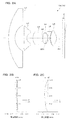
- FIG. 2A is a cross-sectional view of the single-focus imaging optical system of Example 1.
- FIGS. 2B and 2C are longitudinal aberration diagrams of Example 1.
- FIG. 3A is a cross-sectional view of the single focus imaging optical system of Example 2
- FIGS. 3B and 3C are longitudinal aberration diagrams of Example 2.
- FIG. 4A is a cross-sectional view of the single focus imaging optical system of Example 3
- FIGS. 4B and 4C are longitudinal aberration diagrams of Example 3.
- FIG. FIG. 5A is a cross-sectional view of the single focus imaging optical system of Example 4, and FIGS. 5B and 5C are longitudinal aberration diagrams of Example 4.
- FIG. 6A is a cross-sectional view of the single-focus imaging optical system of Example 5, and FIGS. 6B and 6C are longitudinal aberration diagrams of Example 5.
- FIG. 7A is a cross-sectional view of the single-focus imaging optical system of Example 6, and FIGS. 7B and 7C are longitudinal aberration diagrams of Example 6.
- FIG. 8A is a cross-sectional view of the single focus imaging optical system of Example 7, and FIGS. 8B and 8C are longitudinal aberration diagrams of Example 7.
- FIG. 9A is a cross-sectional view of the single focus imaging optical system of Example 8, and FIGS. 9B and 9C are longitudinal aberration diagrams of Example 8.
- FIG. 10A is a cross-sectional view of the single-focus imaging optical system of Example 9, and FIGS. 10B and 10C are longitudinal aberration diagrams of Example 9.
- FIG. 10A is a cross-sectional view of the single-focus imaging optical system of Example 9 and FIGS. 10B and 10C are longitudinal aberration diagrams of Example 9.
- FIG. 1 is a view showing an imaging device 100 according to an embodiment of the present invention.
- the imaging device 100 includes a camera module 30 for forming an image signal, and a processing unit 60 that causes the camera module 30 to operate to exhibit a function as the imaging device 100.
- the camera module 30 includes a lens unit 40 having a single focus imaging optical system 10 therein, and a sensor unit 50 for converting an object image formed by the single focus imaging optical system 10 into an image signal.
- the camera module 30 incorporates the single focus imaging optical system 10 described in detail below, and a wide angle of view can be secured, and the imaging device 100 having a small size and high optical performance can be provided.
- the lens unit 40 includes a single focus imaging optical system 10 which is a wide-angle optical system, and a lens barrel 41 to which the single focus imaging optical system 10 is assembled.
- the single-focus imaging optical system 10 includes first to sixth lenses L1 to L6, which will be described in detail later, and the first to third lenses L1 to L3 forming the front group on the object side with the diaphragm ST interposed therebetween. And the fourth to sixth lenses L4 to L6 constituting the rear group on the image side.
- the lens barrel 41 is formed of metal, resin, a mixture of resin and glass fiber, or the like, and the single focus imaging optical system 10 is housed and held inside.
- the lens barrel 41 is formed of a mixture of metal and resin with glass fiber, the lens barrel 41 is less likely to expand than the resin, and the single focus imaging optical system 10 can be stably fixed.
- the lens barrel 41 has an opening OP1 through which a ray bundle from the object side is made incident.
- the first to sixth lenses L1 to L6 constituting the single-focus imaging optical system 10 are held directly or indirectly on the inner surface side of the lens barrel 41 at their flange portions or outer peripheral portions, and in the optical axis AX direction And the position perpendicular to the optical axis AX.
- the sensor unit 50 includes a solid-state imaging device 51 that photoelectrically converts an object image formed by the single-focus imaging optical system 10, a substrate 52 supporting the solid-state imaging device 51 from behind and provided with wiring, peripheral circuits, and the like. And a sensor holder 53 for holding the solid-state imaging device 51 via the substrate 52.
- the solid-state imaging device 51 is, for example, a CMOS type image sensor.
- the substrate 52 includes wires for operating the solid-state imaging device 51, peripheral circuits, and the like.
- the sensor holder 53 is formed of a resin or other material, and supports the parallel flat plate F so as to face the solid-state image sensor 51 as well as positioning the solid-state image sensor 51 with respect to the optical axis AX.
- the lens barrel 41 of the lens unit 40 is fixed in a state of being positioned so as to be fitted to the sensor holder 53.
- the solid-state imaging device (imaging device) 51 includes a photoelectric conversion unit 51a having an imaging surface I, and a signal processing circuit (not shown) is formed around the photoelectric conversion unit 51a.
- the solid-state imaging device 51 is not limited to the above-described CMOS-type image sensor, and may be one to which a CCD or the like is applied.
- the parallel flat plate F disposed between the single focus imaging optical system 10 and the solid state imaging device 51 is an optical low pass filter, a seal glass of the solid state imaging device, an IR cut filter, a wavelength selection filter, or the like.
- the processing unit 60 includes a drive unit 61, an input unit 62, a storage unit 63, a display unit 64, and a control unit 68.
- the drive unit 61 operates the solid-state imaging device 51 by receiving supply of a digital control signal or the like from the control unit 68.
- the drive unit 61 receives YUV and other digital pixel signals as image data from the solid-state imaging device 51 and transfers the digital pixel signals to the control unit 68.
- the input unit 62 is a unit for receiving a user's operation or a command from an external device
- the storage unit 63 is a unit for storing information necessary for the operation of the imaging device 100, image data acquired by the camera module 30, etc.
- the display unit 64 is a portion that displays information to be presented to the user, a photographed image, and the like.
- the control unit 68 integrally controls the operations of the drive unit 61, the input unit 62, the storage unit 63, and the like, and can perform various image processing on image data obtained by the camera module 30, for example. Such image data can be output to an external circuit.
- the details of the single-focus imaging optical system 10 according to the embodiment will be described below with reference to FIG.
- the single-focus imaging optical system 10 illustrated in FIG. 1 has the same configuration as the single-focus imaging optical system 10A of Example 1 described later.
- the illustrated single-focus imaging optical system 10 is a wide-angle lens for forming an object image on the imaging surface I of the solid-state imaging device 51, and is a first lens L1 having negative refractive power in order from the object side.
- the first lens L1 is a spherical type lens formed of glass and composed of a spherical surface
- the fourth lens L4 is an aspheric type lens formed of glass and composed of an aspheric surface.
- the second, third, fifth and sixth lenses L2, L3, L5 and L6 are respectively made of plastic and have at least one aspheric shape.
- the single-focus imaging optical system 10 is a wide-angle lens having an angle of view of 180 ° or more, and can be reduced in the diameter of the front lens by adopting a retrofocus type preceded by a negative lens. A back focus sufficient to install sealing glass or the like of the imaging element 51 can be secured.
- the negative lens into a two-lens configuration of the first and second lenses L1 and L2, it is possible to divide negative power and to improve the performance and reduce the error sensitivity more than when one negative lens is provided. .
- the third lens L3 biconvex shape a sufficient positive power is secured, and in the lens group before the stop ST, the aberration generated in the negative lens of the first lens L1 and the second lens L2 is cancelled.
- the fourth lens L4, the fifth lens L5, and the sixth lens L6 are arranged to be a positive / negative positive power arrangement, so-called triplets can be obtained, and aberration correction in the lens group behind the aperture stop ST becomes good. Furthermore, if the object side surface S51 of the fifth lens L5 is a convex surface in the paraxial region, the principal point interval between the fourth lens L4 and the fifth lens L5 increases, and the fourth and fifth lenses L4 and L5 have the same power. However, since the combined power of the fourth lens L4 and the fifth lens L5 can be made stronger than when the principal point interval is narrow, aberration and error sensitivity generated in each of the fourth and fifth lenses L4 and L5 are suppressed.
- the single-focus imaging optical system 10 can be miniaturized.
- the fourth and fifth lenses L4 and L5, the fifth and sixth lenses L5 and L6, and the like may be cemented to each other in order to suppress chromatic aberration, spherical aberration, and error sensitivity.
- the single-focus imaging optical system 10 satisfies the following conditional expression (1). 0.1 ⁇ (d34 / f) / (tan (w / 2)) ⁇ 0.8 (1)
- the value d34 is the distance between the third lens L3 and the fourth lens L4
- the value f is the focal length of the entire system
- the value w is the maximum half angle of view.
- the single-focus imaging optical system 10 satisfies the following conditional expression (2). -3 ⁇ f2 / f ⁇ -1 (2)
- the value f2 is the focal length of the second lens L2.
- the refractive power of the second lens L2 does not become too strong, and the performance variation due to the astigmatism and the manufacturing error generated here can be suppressed. it can.
- the value f2 / f of the conditional expression (2) is set below the upper limit or more, the refractive power of the second lens L2 does not become too weak, and the optical system can be kept compact.
- the single focus imaging optical system 10 satisfies the following conditional expression (3). 3 ⁇ f3 / f ⁇ 6 (3)
- the value f3 is the focal length of the third lens L3.
- the refractive power of the third lens L3 does not become too strong, and the performance variation due to the spherical aberration and coma aberration generated here and the manufacturing error is suppressed. be able to.
- the refractive power of the third lens L3 does not become too weak, and the optical system can be kept compact.
- the single focus imaging optical system 10 satisfies the following conditional expression (4). -3 ⁇ f5 / f ⁇ -1 (4)
- the value f5 is the focal length of the fifth lens.
- the refractive power of the fifth lens L5 does not become too strong, and suppressing the performance variation due to the astigmatism and the manufacturing error generated here. it can.
- the refractive power of the fifth lens L5 does not become too weak, and the optical system can be kept compact.
- the single focus imaging optical system 10 satisfies the following conditional expression (5). 2 ⁇ f1 / f2 ⁇ 5.5 (5)
- the refractive power of the first lens L1 does not become too strong relative to the second lens L2, and the burden on the first lens L1 can be relatively reduced. Astigmatism and error sensitivity generated in the first lens L1 can be suppressed.
- the refractive power of the second lens L2 does not become too strong relative to the first lens L1, and the load on the second lens L2 is relatively reduced. As a result, it is possible to suppress astigmatism and error sensitivity generated in the second lens L2.
- the single focus imaging optical system 10 satisfies the following conditional expression (6). ⁇ 8 ⁇ f1 / f ⁇ ⁇ 5 (6)
- the refractive power of the first lens L1 does not become too strong, and the performance variation due to the astigmatism and the manufacturing error generated here can be suppressed. it can.
- the refractive power of the first lens L1 does not become too weak and the diameter of the front lens does not become too large. can do.
- the single focus imaging optical system 10 satisfies the following conditional expression (7). 1.5 ⁇ f4 / f ⁇ 3 (7)
- the value f4 is the focal length of the fourth lens L4.
- the refractive power of the fourth lens L4 does not become too strong, and the performance variation due to the spherical aberration and coma aberration generated here and the manufacturing error is suppressed. be able to.
- the refractive power of the fourth lens L4 does not become too weak, and the optical system can be kept compact.
- the single-focus imaging optical system 10 satisfies the following conditional expression (8). ⁇ 0.4 ⁇ f ⁇ ⁇ (1 / fplk) ⁇ ⁇ 0.2 (8)
- the value fplk is the focal length of the k-th plastic lens from the object side.
- the distance from the lens to the focal point does not become too short when changing, and the distance from the lens to the focal point does not become too long when the temperature changes to the low temperature side.
- the value f ⁇ ⁇ (1 / fplk) in the conditional expression (8) is set to the upper limit or less, the sum of the focal lengths of the plastic lenses does not become too small to the negative value side.
- the distance from the lens to the focal point does not become too long when changed, and the distance from the lens to the focal point does not become too short when the temperature changes to the low temperature side.
- plasticizing the lenses L2, L3, L5, and L6 reduces the weight of the optical system, and adds an aspheric surface by injection molding or the like to increase the shape freedom more than at a spherical surface, and correct aberrations well.
- the single focus imaging optical system 10 satisfies the following conditional expression (9).
- the value LL4 is the Abbe number of the fourth lens L4.
- the single focus imaging optical system 10 satisfies the following conditional expression (10). 1.8 ⁇ nL1 (10)
- the value nL1 is the refractive index of the first lens L1.
- the radius of curvature can be relaxed even if the first lens L1 has the same power, and astigmatism and the like generated on this surface can be reduced. Further, even if the power of the first lens L1 is increased to reduce the diameter of the front lens, aberrations are relatively unlikely to occur, and both downsizing and high performance of the optical system can be achieved.
- the single-focus imaging optical system 10 may further include another optical element (for example, a lens, a filter member, and the like) that does not substantially have a refractive power.
- another optical element for example, a lens, a filter member, and the like
- the single focus imaging optical system 10 of the present embodiment is premised to be used for a fixed focus camera module 30 or an imaging apparatus 100 having no focus function. That is, the lens barrel 41 is not provided with the movable mechanism of the lens.
- the parallel flat plate F is not essential.
- the filter for wavelength selection not have a separately disposed structure but its function be imparted to the lens.
- infrared cut coating may be performed on the surface of one or more lenses.
- security cameras such as surveillance cameras, door phone cameras, authentication cameras or lenses for marketing cameras, lenses for in-vehicle cameras mounted on automobiles or other moving objects
- medical Examples include endoscopes, healthcare measurements, industrial endoscopes and other medical or industrial optical lenses.
- the single-focus imaging optical system 10 or the imaging apparatus 100 may be applied to applications other than these where wide angle is required.
- the surface described with “*” after each surface number is a surface having an aspheric shape, and the shape of the aspheric surface has the vertex of the surface as the origin and the X axis in the optical axis direction.
- the height in the direction perpendicular to the optical axis is denoted by h in the following "Equation 1".
- Ai i-th order aspheric coefficient
- R radius of curvature
- K conical constant
- Example 1 The entire specifications of the single-focus imaging optical system of Example 1 are shown in Table 1 below. [Table 1] f (mm) 1.28 Fno 2.0 w (°) 110.0 ymax (mm) 2.64 TL (mm) 17.28 BF (mm) 2.41
- the data of the lens surface of the single focus imaging optical system of Example 1 is shown in Table 2 below.
- the surface number is represented by “Surf. N”
- the aperture stop is represented by “ST”
- infinity is represented by “INF”.
- Image represents the imaging plane I of the imaging device (or the imaging plane of the single focus imaging optical system).
- the aspherical coefficients of the lens surface of the single focus imaging optical system of Example 1 are shown in Table 3 below. In the following it (including lens data in Tables), and represents an exponent of 10 (for example, 2.5 ⁇ 10 -02) with E (e.g. 2.5E-02).
- FIG. 2A is a cross-sectional view of the single-focus imaging optical system 10A of Example 1 and the like.
- the single-focus imaging optical system 10A includes, in order from the object side, the negative first lens L1, the negative second lens L2, the positive third lens L3, the stop (or aperture stop) ST, and the positive third It consists essentially of a four lens L4, a negative fifth lens L5, and a positive sixth lens L6.
- the first and fourth lenses L1 and L4 are made of glass
- the second, third, fifth and sixth lenses L2, L3, L5 and L6 are made of plastic.
- a parallel plate (filter) F of an appropriate thickness is disposed between the sixth lens L6 and the solid-state imaging device 51.
- the parallel flat plate (filter) F is a parallel flat plate on which an optical low pass filter, an IR cut filter, a seal glass of the solid-state imaging device 51, and the like are assumed.
- Reference symbol I indicates an imaging surface which is a projection surface of the solid-state imaging device 51.
- symbol F and I it is the same also in the subsequent Example.
- FIGS. 2B and 2C show longitudinal aberration diagrams (spherical aberration and astigmatism) of the single-focus imaging optical system 10A of Example 1.
- a solid line represents a sagittal image plane, and a dotted line represents a meridional image plane.
- the amount of focus movement (normal temperature) of the plastic lens (specifically, the second, third, fifth, and sixth lenses L2, L3, L5, L6) due to temperature change
- the movement amount when changing from (25 ° C.) to 105 ° C. is ⁇ 0.012 mm.
- Example 2 Table 4 below shows the overall specifications of the single-focus imaging optical system of Example 2. [Table 4] f (mm) 1.29 Fno 2.0 w (°) 110.0 ymax (mm) 2.63 TL (mm) 17.08 BF (mm) 2.41
- FIG. 3A is a cross-sectional view of the single-focus imaging optical system 10B and the like of the second embodiment.
- the single-focus imaging optical system 10B includes, in order from the object side, a negative first lens L1, a negative second lens L2, a positive third lens L3, a stop (or an aperture stop) ST, and a positive third It consists essentially of a four lens L4, a negative fifth lens L5, and a positive sixth lens L6.
- the first and fourth lenses L1 and L4 are made of glass
- the second, third, fifth and sixth lenses L2, L3, L5 and L6 are made of plastic.
- a parallel flat plate F of an appropriate thickness is disposed between the sixth lens L6 and the solid-state imaging device 51.
- FIGS. 3B and 3C show longitudinal aberration diagrams (spherical aberration and astigmatism) of the single-focus imaging optical system 10B of Example 2.
- FIG. 3A shows longitudinal aberration diagrams (spherical aberration and astigmatism) of the single-focus imaging optical system 10B of Example 2.
- the amount of focus movement (normal temperature) of the plastic lens (specifically, the second, third, fifth, and sixth lenses L2, L3, L5, L6) due to temperature change
- the movement amount when changing from (25 ° C.) to 105 ° C. is ⁇ 0.012 mm.
- Table 7 shows the overall specifications of the single-focus imaging optical system of Example 3. [Table 7] f (mm) 1.29 Fno 2.0 w (°) 110.0 ymax (mm) 2.64 TL (mm) 16.86 BF (mm) 2.30
- FIG. 4A is a cross-sectional view of the single-focus imaging optical system 10C of Example 3 and the like.
- the single-focus imaging optical system 10C includes, in order from the object side, a negative first lens L1, a negative second lens L2, a positive third lens L3, a stop (or an aperture stop) ST, and a positive third It consists essentially of a four lens L4, a negative fifth lens L5, and a positive sixth lens L6.
- the first and fourth lenses L1 and L4 are made of glass
- the second, third, fifth and sixth lenses L2, L3, L5 and L6 are made of plastic.
- a parallel flat plate F of an appropriate thickness is disposed between the sixth lens L6 and the solid-state imaging device 51.
- FIGS. 4B and 4C show longitudinal aberration diagrams (spherical aberration and astigmatism) of the single-focus imaging optical system 10C of Example 3.
- FIG. 4B and 4C show longitudinal aberration diagrams (spherical aberration and astigmatism) of the single-focus imaging optical system 10C of Example 3.
- the amount of focus movement (normal temperature) due to the temperature change of the plastic lenses (specifically, the second, third, fifth, and sixth lenses L2, L3, L5, L6)
- the movement amount when changing from (25 ° C.) to 105 ° C. is ⁇ 0.012 mm.
- Example 4 The entire specifications of the single-focus imaging optical system of Example 4 are shown in Table 10 below. [Table 10] f (mm) 1.29 Fno 2.0 w (°) 110.0 ymax (mm) 2.64 TL (mm) 16.83 BF (mm) 2.26
- FIG. 5A is a cross-sectional view of the single focus imaging optical system 10D and the like of the fourth embodiment.
- the single-focus imaging optical system 10D includes, in order from the object side, a negative first lens L1, a negative second lens L2, a positive third lens L3, a stop (or an aperture stop) ST, and a positive third It consists essentially of a four lens L4, a negative fifth lens L5, and a positive sixth lens L6.
- the first and fourth lenses L1 and L4 are made of glass
- the second, third, fifth and sixth lenses L2, L3, L5 and L6 are made of plastic.
- a parallel flat plate F of an appropriate thickness is disposed between the sixth lens L6 and the solid-state imaging device 51.
- FIG. 5B and 5C show longitudinal aberration diagrams (spherical aberration and astigmatism) of the single-focus imaging optical system 10D of Example 4.
- FIG. 5B and 5C show longitudinal aberration diagrams (spherical aberration and astigmatism) of the single-focus imaging optical system 10D of Example 4.
- the amount of focus movement (normal temperature) of the plastic lens (specifically, the second, third, fifth, and sixth lenses L2, L3, L5, L6) due to temperature change
- the movement amount when changing from (25 ° C.) to 105 ° C. is ⁇ 0.012 mm.
- Example 5 The entire specifications of the single-focus imaging optical system of Example 5 are shown in Table 13 below. [Table 13] f (mm) 1.36 Fno 2.0 w (°) 110.0 ymax (mm) 2.64 TL (mm) 19.93 BF (mm) 2.59
- FIG. 6A is a cross-sectional view of the single-focus imaging optical system 10E and the like of the fifth embodiment.
- the single-focus imaging optical system 10E includes, in order from the object side, a negative first lens L1, a negative second lens L2, a positive third lens L3, a stop (or an aperture stop) ST, and a positive third It consists essentially of a four lens L4, a negative fifth lens L5, and a positive sixth lens L6.
- the first and fourth lenses L1 and L4 are made of glass
- the second, third, fifth and sixth lenses L2, L3, L5 and L6 are made of plastic.
- a parallel flat plate F of an appropriate thickness is disposed between the sixth lens L6 and the solid-state imaging device 51.
- FIG. 6B and 6C show longitudinal aberration diagrams (spherical aberration and astigmatism) of the single-focus imaging optical system 10E of Example 5.
- FIG. 6B and 6C show longitudinal aberration diagrams (spherical aberration and astigmatism) of the single-focus imaging optical system 10E of Example 5.
- the amount of focus movement (normal temperature) of the plastic lens (specifically, the second, third, fifth, and sixth lenses L2, L3, L5, L6) due to temperature change
- the movement amount when changing from (25 ° C.) to 105 ° C. is 0.009 mm.
- Example 6 The entire specifications of the single-focus imaging optical system of Example 6 are shown in Table 16 below. [Table 16] f (mm) 1.27 Fno 2.0 w (°) 110.0 ymax (mm) 2.64 TL (mm) 16.00 BF (mm) 2.07
- FIG. 7A is a cross-sectional view of the single-focus imaging optical system 10F and the like of the sixth embodiment.
- the single-focus imaging optical system 10F includes, in order from the object side, a negative first lens L1, a negative second lens L2, a positive third lens L3, a stop (or an aperture stop) ST, and a positive third It consists essentially of a four lens L4, a negative fifth lens L5, and a positive sixth lens L6.
- the first and fourth lenses L1 and L4 are made of glass
- the second, third, fifth and sixth lenses L2, L3, L5 and L6 are made of plastic.
- a parallel flat plate F of an appropriate thickness is disposed between the sixth lens L6 and the solid-state imaging device 51.
- FIGS. 7B and 7C show longitudinal aberration diagrams (spherical aberration and astigmatism) of the single-focus imaging optical system 10F of Example 6.
- FIG. 7B and 7C show longitudinal aberration diagrams (spherical aberration and astigmatism) of the single-focus imaging optical system 10F of Example 6.
- the amount of focus movement (normal temperature) of the plastic lenses (specifically, the second, third, fifth, and sixth lenses L2, L3, L5, L6) due to temperature change
- the movement amount when changing from (25 ° C.) to 105 ° C. is ⁇ 0.009 mm.
- Example 7 Table 19 below shows the overall specifications of the single-focus imaging optical system of Example 7. [Table 19] f (mm) 1.07 Fno 2.0 w (°) 110.0 ymax (mm) 2.64 TL (mm) 16.13 BF (mm) 2.06
- FIG. 8A is a cross-sectional view of a single focus imaging optical system 10G and the like according to a seventh example.
- the single-focus imaging optical system 10G includes, in order from the object side, a negative first lens L1, a negative second lens L2, a positive third lens L3, a stop (or an aperture stop) ST, and a positive third It consists essentially of a four lens L4, a negative fifth lens L5, and a positive sixth lens L6.
- the first and fourth lenses L1 and L4 are made of glass
- the second, third, fifth and sixth lenses L2, L3, L5 and L6 are made of plastic.
- a parallel flat plate F of an appropriate thickness is disposed between the sixth lens L6 and the solid-state imaging device 51.
- FIG. 8B and 8C show longitudinal aberration diagrams (spherical aberration and astigmatism) of the single-focus imaging optical system 10G of Example 7.
- FIG. 8B and 8C show longitudinal aberration diagrams (spherical aberration and astigmatism) of the single-focus imaging optical system 10G of Example 7.
- the amount of focus movement (normal temperature) of the plastic lenses (specifically, the second, third, fifth, and sixth lenses L2, L3, L5, L6) due to the temperature change
- the movement amount when changing from (25 ° C.) to 105 ° C. is ⁇ 0.009 mm.
- Example 8 Table 22 below shows the overall specifications of the single-focus imaging optical system of Example 8. [Table 22] f (mm) 1.24 Fno 2.0 w (°) 110.0 ymax (mm) 2.65 TL (mm) 16.56 BF (mm) 2.13
- FIG. 9A is a cross-sectional view of a single focus imaging optical system 10H and the like according to an eighth embodiment.
- the single-focus imaging optical system 10H includes, in order from the object side, a negative first lens L1, a negative second lens L2, a positive third lens L3, a stop (or an aperture stop) ST, and a positive third It consists essentially of a four lens L4, a negative fifth lens L5, and a positive sixth lens L6.
- the first and fourth lenses L1 and L4 are made of glass
- the second, third, fifth and sixth lenses L2, L3, L5 and L6 are made of plastic.
- a parallel flat plate F of an appropriate thickness is disposed between the sixth lens L6 and the solid-state imaging device 51.
- FIG. 9B and 9C show longitudinal aberration diagrams (spherical aberration and astigmatism) of the single-focus imaging optical system 10H of Example 8.
- FIG. 9B and 9C show longitudinal aberration diagrams (spherical aberration and astigmatism) of the single-focus imaging optical system 10H of Example 8.
- the amount of focus movement (normal temperature) of the plastic lenses (specifically, the second, third, fifth, and sixth lenses L2, L3, L5, L6) due to the temperature change
- the movement amount when changing from (25 ° C.) to 105 ° C. is ⁇ 0.010 mm.
- Table 25 below shows the overall specifications of the single-focus imaging optical system of Example 9. [Table 25] f (mm) 1.33 Fno 2.0 w (°) 110.0 ymax (mm) 2.65 TL (mm) 15.98 BF (mm) 2.16
- FIG. 10A is a cross-sectional view of a single focus imaging optical system 10I and the like according to a ninth example.
- the single-focus imaging optical system 10I includes, in order from the object side, a negative first lens L1, a negative second lens L2, a positive third lens L3, a stop (or an aperture stop) ST, and a positive third It consists essentially of a four lens L4, a negative fifth lens L5, and a positive sixth lens L6.
- the first and fourth lenses L1 and L4 are made of glass
- the second, third, fifth and sixth lenses L2, L3, L5 and L6 are made of plastic.
- a parallel flat plate F of an appropriate thickness is disposed between the sixth lens L6 and the solid-state imaging device 51.
- FIG. 10B and 10C show longitudinal aberration diagrams (spherical aberration and astigmatism) of the single-focus imaging optical system 10I of Example 9.
- FIG. 10B and 10C show longitudinal aberration diagrams (spherical aberration and astigmatism) of the single-focus imaging optical system 10I of Example 9.
- the amount of focus movement normal temperature due to temperature change of the plastic lenses (specifically, the second, third, fifth, and sixth lenses L2, L3, L5, L6)
- the movement amount when changing from (25 ° C.) to 105 ° C. is ⁇ 0.012 mm.
- Table 28 summarizes the values of Examples 1 to 9 corresponding to the conditional expressions (1) to (10) for reference. [Table 28]
- the single-focus imaging optical system according to the embodiment has been described above, but the single-focus imaging optical system according to the present invention is not limited to the above-described one.
- a lens or the like having substantially no refractive power can be added between the first to sixth lenses L1 to L6, or the image side or the object side thereof.
- the filter that is a parallel flat plate is divided into two It is also possible to take a configuration such as giving the role of
Abstract
Provided is a single-focus imaging optical system that is small-sized and has high optical performance despite having a wide angle of view. A single-focus imaging optical system 10 essentially comprises, in order from an object side, a first lens L1 having a negative refractive power, a biconcave second lens L2, a biconvex third lens L3, a diaphragm ST, a fourth lens L4 having a positive refractive power, a negative fifth lens L5 in which the object-side surface thereof is convex in the paraxial region, and a sixth lens L6 having a positive refractive power.
Description
本発明は、広角の単焦点撮像光学系、レンズユニット、及び撮像装置に関し、特に180°以上の画角を有する単焦点撮像光学系等に関する。
The present invention relates to a wide-angle single-focus imaging optical system, a lens unit, and an imaging apparatus, and more particularly to a single-focus imaging optical system having an angle of view of 180 ° or more.
近年、車載用の撮像光学系では、180°以上の画角を有し、小型かつ解像度の高いものが要望されている。この種の撮像光学系として、物体側から順に、負レンズ、負レンズ、正レンズ、正レンズ、負レンズ、及び正レンズを配置した6枚構成で、第3レンズの像側の面を平面又は凹面としたものが公知となっている(例えば、特許文献1参照)。
In recent years, in the on-vehicle imaging optical system, it is required to have a small size and high resolution with an angle of view of 180 ° or more. As an imaging optical system of this type, in a six-lens configuration in which a negative lens, a negative lens, a positive lens, a positive lens, a negative lens, and a positive lens are arranged in order from the object side. One having a concave surface is known (see, for example, Patent Document 1).
しかし、特許文献1の撮像光学系では、広い画角を確保できているが、光学全長が長い、サジタル像面湾曲が大きい、周辺光量比が低い等、光学系の大きさや光学性能の観点で上記要望を十分満たしているとは言えなかった。
However, in the imaging optical system of Patent Document 1, a wide angle of view can be secured, but the total optical length is long, the sagittal field curvature is large, the peripheral light amount ratio is low, etc. It could not be said that the above requirements were sufficiently met.
本発明は、上記背景技術に鑑みてなされたものであり、広い画角を有しつつも小型で高い光学性能を有する単焦点撮像光学系を提供することを目的とする。
The present invention has been made in view of the above background art, and an object of the present invention is to provide a single-focus imaging optical system having a small size and high optical performance while having a wide angle of view.
また、本発明は、上記単焦点撮像光学系を備えたレンズユニット及び撮像装置を提供することを目的とする。
Another object of the present invention is to provide a lens unit and an imaging apparatus provided with the single focus imaging optical system.
上記した目的のうち少なくとも一つを実現するために、本発明の一側面を反映した単焦点撮像光学系は、物体側から順に、負の屈折力を有する第1レンズと、両凹形状の第2レンズと、両凸形状の第3レンズと、絞りと、正の屈折力を有する第4レンズと、近軸領域で物体側面が凸面である負の第5レンズと、正の屈折力を有する第6レンズとから実質的になる。
In order to achieve at least one of the above objects, the single-focus imaging optical system reflecting one aspect of the present invention includes, in order from the object side, a first lens having negative refractive power, and a first lens having a biconcave shape. 2 lens, a biconvex third lens, an aperture stop, a fourth lens having a positive refractive power, a negative fifth lens having a convex object side surface in the near-axis region, and a positive refractive power It substantially consists of the sixth lens.
上記した目的のうち少なくとも一つを実現するために、本発明の一側面を反映したレンズユニットは、上述の単焦点撮像光学系と、単焦点撮像光学系を保持する鏡筒とを備える。
In order to realize at least one of the above objects, a lens unit reflecting one aspect of the present invention includes the above-described single focus imaging optical system and a lens barrel that holds the single focus imaging optical system.
上記した目的のうち少なくとも一つを実現するために、本発明の一側面を反映した撮像装置は、上述の単焦点撮像光学系と、単焦点撮像光学系から得られる像を検出する撮像素子とを備える。
In order to realize at least one of the above objects, an imaging apparatus reflecting one aspect of the present invention includes the above-described single focus imaging optical system, and an imaging element for detecting an image obtained from the single focus imaging optical system. Equipped with
図1は、本発明の一実施形態に係る撮像装置100を示す図である。撮像装置100は、画像信号を形成するためのカメラモジュール30と、カメラモジュール30を動作させることにより撮像装置100としての機能を発揮させる処理部60とを備える。
FIG. 1 is a view showing an imaging device 100 according to an embodiment of the present invention. The imaging device 100 includes a camera module 30 for forming an image signal, and a processing unit 60 that causes the camera module 30 to operate to exhibit a function as the imaging device 100.
カメラモジュール30は、単焦点撮像光学系10を内蔵するレンズユニット40と、単焦点撮像光学系10によって形成された被写体像を画像信号に変換するセンサー部50とを備える。カメラモジュール30は、以下に詳述する単焦点撮像光学系10を組み込んでおり、広い画角が確保され、小型で高い光学性能を有する撮像装置100を提供することができる。
The camera module 30 includes a lens unit 40 having a single focus imaging optical system 10 therein, and a sensor unit 50 for converting an object image formed by the single focus imaging optical system 10 into an image signal. The camera module 30 incorporates the single focus imaging optical system 10 described in detail below, and a wide angle of view can be secured, and the imaging device 100 having a small size and high optical performance can be provided.
レンズユニット40は、広角光学系である単焦点撮像光学系10と、単焦点撮像光学系10を組み付けた鏡筒41とを備える。
The lens unit 40 includes a single focus imaging optical system 10 which is a wide-angle optical system, and a lens barrel 41 to which the single focus imaging optical system 10 is assembled.
単焦点撮像光学系10は、後に詳述するが、第1~第6レンズL1~L6を備え、絞りSTを挟んで、物体側に前群を構成する第1~第3レンズL1~L3を有し、像側に後群を構成する第4~第6レンズL4~L6を有する。
The single-focus imaging optical system 10 includes first to sixth lenses L1 to L6, which will be described in detail later, and the first to third lenses L1 to L3 forming the front group on the object side with the diaphragm ST interposed therebetween. And the fourth to sixth lenses L4 to L6 constituting the rear group on the image side.
鏡筒41は、金属、樹脂、樹脂にグラスファイバーを混合したもの等で形成され、単焦点撮像光学系10を内部に収納し保持している。鏡筒41を金属、樹脂にグラスファイバーを混合したもので形成する場合、樹脂よりも膨張しにくく、単焦点撮像光学系10を安定して固定することができる。鏡筒41は、物体側からの光線束を入射させる開口OP1を有する。
The lens barrel 41 is formed of metal, resin, a mixture of resin and glass fiber, or the like, and the single focus imaging optical system 10 is housed and held inside. When the lens barrel 41 is formed of a mixture of metal and resin with glass fiber, the lens barrel 41 is less likely to expand than the resin, and the single focus imaging optical system 10 can be stably fixed. The lens barrel 41 has an opening OP1 through which a ray bundle from the object side is made incident.
単焦点撮像光学系10を構成する第1~第6レンズL1~L6は、それらのフランジ部若しくは外周部において鏡筒41の内面側に直接的又は間接的に保持されており、光軸AX方向及び光軸AXに垂直な方向に関しての位置決めがなされている。
The first to sixth lenses L1 to L6 constituting the single-focus imaging optical system 10 are held directly or indirectly on the inner surface side of the lens barrel 41 at their flange portions or outer peripheral portions, and in the optical axis AX direction And the position perpendicular to the optical axis AX.
センサー部50は、単焦点撮像光学系10によって形成された被写体像を光電変換する固体撮像素子51と、この固体撮像素子51を背後から支持するとともに配線、周辺回路等を設けた基板52と、基板52を介して固体撮像素子51を保持するセンサーホルダー53とを備える。固体撮像素子51は、例えばCMOS型のイメージセンサーである。基板52は、固体撮像素子51を動作させるための配線、周辺回路等を備える。センサーホルダー53は、樹脂その他の材料で形成され、固体撮像素子51を光軸AX対して位置決めするだけでなく、固体撮像素子51に対向するように平行平板Fを支持している。レンズユニット40の鏡筒41はセンサーホルダー53に嵌合するように位置決めされた状態で固定されている。
The sensor unit 50 includes a solid-state imaging device 51 that photoelectrically converts an object image formed by the single-focus imaging optical system 10, a substrate 52 supporting the solid-state imaging device 51 from behind and provided with wiring, peripheral circuits, and the like. And a sensor holder 53 for holding the solid-state imaging device 51 via the substrate 52. The solid-state imaging device 51 is, for example, a CMOS type image sensor. The substrate 52 includes wires for operating the solid-state imaging device 51, peripheral circuits, and the like. The sensor holder 53 is formed of a resin or other material, and supports the parallel flat plate F so as to face the solid-state image sensor 51 as well as positioning the solid-state image sensor 51 with respect to the optical axis AX. The lens barrel 41 of the lens unit 40 is fixed in a state of being positioned so as to be fitted to the sensor holder 53.
固体撮像素子(撮像素子)51は、撮像面Iを有する光電変換部51aを備え、その周囲には、不図示の信号処理回路が形成されている。なお、固体撮像素子51は、上述のCMOS型のイメージセンサーに限るものでなく、CCDその他を適用したものであってもよい。
The solid-state imaging device (imaging device) 51 includes a photoelectric conversion unit 51a having an imaging surface I, and a signal processing circuit (not shown) is formed around the photoelectric conversion unit 51a. The solid-state imaging device 51 is not limited to the above-described CMOS-type image sensor, and may be one to which a CCD or the like is applied.
単焦点撮像光学系10と固体撮像素子51との間に配置された平行平板Fは、光学的ローパスフィルター、固体撮像素子のシールガラス、IRカットフィルター、波長選択フィルター等である。
The parallel flat plate F disposed between the single focus imaging optical system 10 and the solid state imaging device 51 is an optical low pass filter, a seal glass of the solid state imaging device, an IR cut filter, a wavelength selection filter, or the like.
処理部60は、駆動部61と、入力部62と、記憶部63と、表示部64と、制御部68とを備える。駆動部61は、制御部68からデジタル制御信号等の供給を受けることによって、固体撮像素子51を動作させている。駆動部61は、固体撮像素子51から画像データとしてYUVその他のデジタル画素信号を受け取って制御部68に転送する。入力部62は、ユーザーの操作或いは外部装置からのコマンドを受け付ける部分であり、記憶部63は、撮像装置100の動作に必要な情報、カメラモジュール30によって取得した画像データ等を保管する部分であり、表示部64は、ユーザーに提示すべき情報、撮影した画像等を表示する部分である。制御部68は、駆動部61、入力部62、記憶部63等の動作を統括的に制御しており、例えばカメラモジュール30によって得た画像データに対して種々の画像処理を行うことができ、かかる画像データを外部回路へ出力することができる。
The processing unit 60 includes a drive unit 61, an input unit 62, a storage unit 63, a display unit 64, and a control unit 68. The drive unit 61 operates the solid-state imaging device 51 by receiving supply of a digital control signal or the like from the control unit 68. The drive unit 61 receives YUV and other digital pixel signals as image data from the solid-state imaging device 51 and transfers the digital pixel signals to the control unit 68. The input unit 62 is a unit for receiving a user's operation or a command from an external device, and the storage unit 63 is a unit for storing information necessary for the operation of the imaging device 100, image data acquired by the camera module 30, etc. The display unit 64 is a portion that displays information to be presented to the user, a photographed image, and the like. The control unit 68 integrally controls the operations of the drive unit 61, the input unit 62, the storage unit 63, and the like, and can perform various image processing on image data obtained by the camera module 30, for example. Such image data can be output to an external circuit.
以下、図1を参照して、実施形態の単焦点撮像光学系10の詳細について説明する。なお、図1で例示した単焦点撮像光学系10は、後述する実施例1の単焦点撮像光学系10Aと同一の構成となっている。
The details of the single-focus imaging optical system 10 according to the embodiment will be described below with reference to FIG. The single-focus imaging optical system 10 illustrated in FIG. 1 has the same configuration as the single-focus imaging optical system 10A of Example 1 described later.
図示の単焦点撮像光学系10は、固体撮像素子51の撮像面Iに被写体像を結像させる広角レンズであって、物体側からの順で、負の屈折力を有する第1レンズL1、両凹形状の第2レンズL2、両凸形状の第3レンズL3、絞りST、正の屈折力を有する第4レンズL4、近軸領域で物体側面が凸面である負の第5レンズL5、及び正の屈折力を有する第6レンズL6からなる。ここで、第1レンズL1は、ガラスで形成され、球面で構成される球面タイプのレンズであり、第4レンズL4は、ガラスで形成され、非球面で構成される非球面タイプのレンズである。第2、第3、第5、及び第6レンズL2,L3,L5,L6は、プラスチックでそれぞれ形成され、少なくとも1つの非球面形状をそれぞれ有する。
The illustrated single-focus imaging optical system 10 is a wide-angle lens for forming an object image on the imaging surface I of the solid-state imaging device 51, and is a first lens L1 having negative refractive power in order from the object side. A concave second lens L2, a biconvex third lens L3, an aperture stop ST, a fourth lens L4 having a positive refractive power, a negative fifth lens L5 having a convex object side surface in the near-axis region, and a positive lens And a sixth lens L6 having a refractive power of Here, the first lens L1 is a spherical type lens formed of glass and composed of a spherical surface, and the fourth lens L4 is an aspheric type lens formed of glass and composed of an aspheric surface. . The second, third, fifth and sixth lenses L2, L3, L5 and L6 are respectively made of plastic and have at least one aspheric shape.
この単焦点撮像光学系10は、180°以上の画角を有する広角レンズであり、負レンズ先行のレトロフォーカス型とすることにより前玉径を小さくでき、各種フィルターとして機能する平行平板F、固体撮像素子51の封止ガラス等を設置するのに十分なバックフォーカスを確保できる。また、負レンズを第1及び第2レンズL1,L2の2枚構成とすることで、負のパワーを分割し、負レンズが1枚のときよりも性能向上及び誤差感度低減を図ることができる。また、第3レンズL3を両凸形状とすることで十分な正パワーを確保し、絞りSTより前のレンズ群において、第1レンズL1や第2レンズL2の負レンズで発生する収差を打消し良好な光学性能を確保できる。さらに、第4レンズL4、第5レンズL5、及び第6レンズL6を正負正のパワー配置とすることで、いわゆるトリプレットとなり、絞りSTより後ろのレンズ群での収差補正が良好となる。さらに、第5レンズL5の物体側面S51が近軸領域で凸面であると、第4レンズL4と第5レンズL5との主点間隔は広がり、第4及び第5レンズL4,L5がそれぞれ同じパワーでも、第4レンズL4と第5レンズL5との合成パワーを主点間隔が狭いときよりも強めることができるため、第4及び第5レンズL4,L5のそれぞれで発生する収差や誤差感度を抑制しながら単焦点撮像光学系10を小型化することができる。なお、色収差、球面収差や誤差感度抑制のため、第4及び第5レンズL4,L5や、第5及び第6レンズL5,L6等を互いに接合してもよい。
The single-focus imaging optical system 10 is a wide-angle lens having an angle of view of 180 ° or more, and can be reduced in the diameter of the front lens by adopting a retrofocus type preceded by a negative lens. A back focus sufficient to install sealing glass or the like of the imaging element 51 can be secured. In addition, by making the negative lens into a two-lens configuration of the first and second lenses L1 and L2, it is possible to divide negative power and to improve the performance and reduce the error sensitivity more than when one negative lens is provided. . Also, by making the third lens L3 biconvex shape, a sufficient positive power is secured, and in the lens group before the stop ST, the aberration generated in the negative lens of the first lens L1 and the second lens L2 is cancelled. Good optical performance can be secured. Further, by arranging the fourth lens L4, the fifth lens L5, and the sixth lens L6 to be a positive / negative positive power arrangement, so-called triplets can be obtained, and aberration correction in the lens group behind the aperture stop ST becomes good. Furthermore, if the object side surface S51 of the fifth lens L5 is a convex surface in the paraxial region, the principal point interval between the fourth lens L4 and the fifth lens L5 increases, and the fourth and fifth lenses L4 and L5 have the same power. However, since the combined power of the fourth lens L4 and the fifth lens L5 can be made stronger than when the principal point interval is narrow, aberration and error sensitivity generated in each of the fourth and fifth lenses L4 and L5 are suppressed. Thus, the single-focus imaging optical system 10 can be miniaturized. The fourth and fifth lenses L4 and L5, the fifth and sixth lenses L5 and L6, and the like may be cemented to each other in order to suppress chromatic aberration, spherical aberration, and error sensitivity.
単焦点撮像光学系10は、以下の条件式(1)を満たす。
0.1<(d34/f)/(tan(w/2))<0.8 … (1)
ここで、値d34は第3レンズL3と第4レンズL4との間隔であり、値fは全系の焦点距離であり、値wは最大半画角である。 The single-focus imagingoptical system 10 satisfies the following conditional expression (1).
0.1 <(d34 / f) / (tan (w / 2)) <0.8 (1)
Here, the value d34 is the distance between the third lens L3 and the fourth lens L4, the value f is the focal length of the entire system, and the value w is the maximum half angle of view.
0.1<(d34/f)/(tan(w/2))<0.8 … (1)
ここで、値d34は第3レンズL3と第4レンズL4との間隔であり、値fは全系の焦点距離であり、値wは最大半画角である。 The single-focus imaging
0.1 <(d34 / f) / (tan (w / 2)) <0.8 (1)
Here, the value d34 is the distance between the third lens L3 and the fourth lens L4, the value f is the focal length of the entire system, and the value w is the maximum half angle of view.
上記条件式(1)の値(d34/f)/(tan(w/2))が下限を上回ることで、第3レンズL3と第4レンズL4との間隔が狭くなりすぎず、干渉を防げたり、両レンズの誤差感度を抑制したりすることができる。一方、上記条件式の値(d34/f)/(tan(w/2))が上限を下回ることで光学系の大型化を防ぐことができる。
When the value (d34 / f) / (tan (w / 2)) of the conditional expression (1) exceeds the lower limit, the distance between the third lens L3 and the fourth lens L4 does not become too narrow and interference is prevented. And the error sensitivity of both lenses can be suppressed. On the other hand, when the value (d34 / f) / (tan (w / 2)) of the above conditional expression falls below the upper limit, the enlargement of the optical system can be prevented.
単焦点撮像光学系10は、以下の条件式(2)を満たす。
-3≦f2/f≦-1 … (2)
ここで、値f2は第2レンズL2の焦点距離である。 The single-focus imagingoptical system 10 satisfies the following conditional expression (2).
-3 ≦ f2 / f ≦ -1 (2)
Here, the value f2 is the focal length of the second lens L2.
-3≦f2/f≦-1 … (2)
ここで、値f2は第2レンズL2の焦点距離である。 The single-focus imaging
-3 ≦ f2 / f ≦ -1 (2)
Here, the value f2 is the focal length of the second lens L2.
上記条件式(2)の値f2/fを上限以下とすることで、第2レンズL2の屈折力が強くなりすぎず、ここで発生する非点収差や、製造誤差による性能変動を抑えることができる。一方、上記条件式(2)の値f2/fを下限以上とすることで、第2レンズL2の屈折力が弱くなりすぎず、光学系を小型に維持することができる。
By setting the value f2 / f of the conditional expression (2) below the upper limit, the refractive power of the second lens L2 does not become too strong, and the performance variation due to the astigmatism and the manufacturing error generated here can be suppressed. it can. On the other hand, by setting the value f2 / f of the conditional expression (2) to the lower limit or more, the refractive power of the second lens L2 does not become too weak, and the optical system can be kept compact.
単焦点撮像光学系10は、以下の条件式(3)を満たす。
3≦f3/f≦6 … (3)
ここで、値f3は第3レンズL3の焦点距離である。 The single focus imagingoptical system 10 satisfies the following conditional expression (3).
3 ≦ f3 / f ≦ 6 (3)
Here, the value f3 is the focal length of the third lens L3.
3≦f3/f≦6 … (3)
ここで、値f3は第3レンズL3の焦点距離である。 The single focus imaging
3 ≦ f3 / f ≦ 6 (3)
Here, the value f3 is the focal length of the third lens L3.
上記条件式(3)の値f3/fを下限以上とすることで、第3レンズL3の屈折力が強くなりすぎず、ここで発生する球面収差及びコマ収差や、製造誤差による性能変動を抑えることができる。一方、上記条件式(3)の値f3/fを上限以下とすることで、第3レンズL3の屈折力が弱くなりすぎず、光学系を小型に維持することができる。
By setting the value f3 / f of the conditional expression (3) to the lower limit or more, the refractive power of the third lens L3 does not become too strong, and the performance variation due to the spherical aberration and coma aberration generated here and the manufacturing error is suppressed. be able to. On the other hand, by setting the value f3 / f of the conditional expression (3) below the upper limit, the refractive power of the third lens L3 does not become too weak, and the optical system can be kept compact.
単焦点撮像光学系10は、以下の条件式(4)を満たす。
-3≦f5/f≦-1 … (4)
ここで、値f5は第5レンズの焦点距離である。 The single focus imagingoptical system 10 satisfies the following conditional expression (4).
-3 ≦ f5 / f ≦ -1 (4)
Here, the value f5 is the focal length of the fifth lens.
-3≦f5/f≦-1 … (4)
ここで、値f5は第5レンズの焦点距離である。 The single focus imaging
-3 ≦ f5 / f ≦ -1 (4)
Here, the value f5 is the focal length of the fifth lens.
上記条件式(4)の値f5/fを上限以下とすることで、第5レンズL5の屈折力が強くなりすぎず、ここで発生する非点収差や、製造誤差による性能変動を抑えることができる。一方、上記条件式(4)の値f5/fを下限以上とすることで、第5レンズL5の屈折力が弱くなりすぎず、光学系を小型に維持することができる。
By making the value f5 / f of the conditional expression (4) not more than the upper limit, the refractive power of the fifth lens L5 does not become too strong, and suppressing the performance variation due to the astigmatism and the manufacturing error generated here. it can. On the other hand, by setting the value f5 / f of the conditional expression (4) to the lower limit or more, the refractive power of the fifth lens L5 does not become too weak, and the optical system can be kept compact.
単焦点撮像光学系10は、以下の条件式(5)を満たす。
2≦f1/f2≦5.5 … (5) The single focus imagingoptical system 10 satisfies the following conditional expression (5).
2 ≦ f1 / f2 ≦ 5.5 (5)
2≦f1/f2≦5.5 … (5) The single focus imaging
2 ≦ f1 / f2 ≦ 5.5 (5)
上記条件式(5)の値f1/f2を下限以上とすることで、第1レンズL1の屈折力が第2レンズL2に対し強くなりすぎず、第1レンズL1の負担を比較的減らせるため、第1レンズL1で発生する非点収差や誤差感度を抑制できる。一方、上記条件式(5)の値f1/f2を上限以下とすることで、第2レンズL2の屈折力が第1レンズL1に対し強くなりすぎず、第2レンズL2の負担を比較的減らすことができるため、この第2レンズL2で発生する非点収差や誤差感度を抑制できる。
By setting the value f1 / f2 of the conditional expression (5) above the lower limit, the refractive power of the first lens L1 does not become too strong relative to the second lens L2, and the burden on the first lens L1 can be relatively reduced. Astigmatism and error sensitivity generated in the first lens L1 can be suppressed. On the other hand, by setting the value f1 / f2 of the conditional expression (5) below the upper limit, the refractive power of the second lens L2 does not become too strong relative to the first lens L1, and the load on the second lens L2 is relatively reduced. As a result, it is possible to suppress astigmatism and error sensitivity generated in the second lens L2.
単焦点撮像光学系10は、以下の条件式(6)を満たす。
-8≦f1/f≦-5 … (6) The single focus imagingoptical system 10 satisfies the following conditional expression (6).
−8 ≦ f1 / f ≦ −5 (6)
-8≦f1/f≦-5 … (6) The single focus imaging
−8 ≦ f1 / f ≦ −5 (6)
上記条件式(6)の値f1/fを上限以下とすることで、第1レンズL1の屈折力が強くなりすぎず、ここで発生する非点収差や、製造誤差による性能変動を抑えることができる。一方、上記条件式(6)の値f1/fを下限以上とすることで、第1レンズL1の屈折力が弱くなりすぎず、前玉径が大きくなりすぎず、ひいては光学系を小型に維持することができる。
By making the value f1 / f of the conditional expression (6) not more than the upper limit, the refractive power of the first lens L1 does not become too strong, and the performance variation due to the astigmatism and the manufacturing error generated here can be suppressed. it can. On the other hand, by setting the value f1 / f of the conditional expression (6) to the lower limit or more, the refractive power of the first lens L1 does not become too weak and the diameter of the front lens does not become too large. can do.
単焦点撮像光学系10は、以下の条件式(7)を満たす。
1.5≦f4/f≦3 … (7)
ここで、値f4は第4レンズL4の焦点距離である。 The single focus imagingoptical system 10 satisfies the following conditional expression (7).
1.5 ≦ f4 / f ≦ 3 (7)
Here, the value f4 is the focal length of the fourth lens L4.
1.5≦f4/f≦3 … (7)
ここで、値f4は第4レンズL4の焦点距離である。 The single focus imaging
1.5 ≦ f4 / f ≦ 3 (7)
Here, the value f4 is the focal length of the fourth lens L4.
上記条件式(7)の値f4/fを下限以上とすることで、第4レンズL4の屈折力が強くなりすぎず、ここで発生する球面収差及びコマ収差や、製造誤差による性能変動を抑えることができる。一方、上記条件式(7)の値f4/fを上限以下とすることで、第4レンズL4の屈折力が弱くなりすぎず、光学系を小型に維持することができる。
By setting the value f4 / f of the conditional expression (7) to the lower limit or more, the refractive power of the fourth lens L4 does not become too strong, and the performance variation due to the spherical aberration and coma aberration generated here and the manufacturing error is suppressed. be able to. On the other hand, by setting the value f4 / f of the conditional expression (7) below the upper limit, the refractive power of the fourth lens L4 does not become too weak, and the optical system can be kept compact.
単焦点撮像光学系10は、以下の条件式(8)を満たす。
-0.4≦f×Σ(1/fplk)≦-0.2 … (8)
ここで、値fplkは物体側からk番目のプラスチックレンズの焦点距離である。 The single-focus imagingoptical system 10 satisfies the following conditional expression (8).
−0.4 ≦ f × Σ (1 / fplk) ≦ −0.2 (8)
Here, the value fplk is the focal length of the k-th plastic lens from the object side.
-0.4≦f×Σ(1/fplk)≦-0.2 … (8)
ここで、値fplkは物体側からk番目のプラスチックレンズの焦点距離である。 The single-focus imaging
−0.4 ≦ f × Σ (1 / fplk) ≦ −0.2 (8)
Here, the value fplk is the focal length of the k-th plastic lens from the object side.
上記のように、第2レンズL2、第3レンズL3、第5レンズL5、及び第6レンズL6をプラスチックレンズとすることにより、絞りの前後において正及び負のパワーのプラスチックレンズを1組ずつ配置でき、温度変化時のピント移動や収差変動を抑えることができる。ここで、第2レンズL2はk=1、第3レンズL3はk=2、第5レンズL5はk=3、第6レンズL6はk=4である。また、上記条件式(8)の値f×Σ(1/fplk)を下限以上とすることで、プラスチックレンズの焦点距離の和が負の値側に大きくなりすぎないので、温度が高温側に変化したときのレンズから焦点までの距離が短くなりすぎなくてすみ、温度が低温側に変化したときのレンズから焦点までの距離が長くなりすぎなくてすむ。一方、上記条件式(8)の値f×Σ(1/fplk)を上限以下とすることで、プラスチックレンズの焦点距離の和が負の値側に小さくなりすぎないので、温度が高温側に変化したときのレンズから焦点までの距離が長くなりすぎなくてすみ、温度が低温側に変化したときのレンズから焦点までの距離が短くなりすぎなくてすむ。また、レンズL2,L3,L5,L6をプラスチック化することで光学系を軽量化したり、射出成形等により非球面を付加することで球面時よりも形状自由度が増し、収差を良好に補正したりすることができる。
As described above, by using the second lens L2, the third lens L3, the fifth lens L5, and the sixth lens L6 as the plastic lenses, one set of plastic lenses of positive and negative power is disposed before and after the stop. It is possible to suppress the focus movement and the aberration fluctuation at the time of temperature change. Here, the second lens L2 is k = 1, the third lens L3 is k = 2, the fifth lens L5 is k = 3, and the sixth lens L6 is k = 4. Further, by setting the value f × Σ (1 / fplk) of the conditional expression (8) to the lower limit or more, the sum of the focal lengths of the plastic lens does not become too large to the negative value side. The distance from the lens to the focal point does not become too short when changing, and the distance from the lens to the focal point does not become too long when the temperature changes to the low temperature side. On the other hand, by setting the value f × Σ (1 / fplk) in the conditional expression (8) to the upper limit or less, the sum of the focal lengths of the plastic lenses does not become too small to the negative value side. The distance from the lens to the focal point does not become too long when changed, and the distance from the lens to the focal point does not become too short when the temperature changes to the low temperature side. In addition, plasticizing the lenses L2, L3, L5, and L6 reduces the weight of the optical system, and adds an aspheric surface by injection molding or the like to increase the shape freedom more than at a spherical surface, and correct aberrations well. Can be
単焦点撮像光学系10は、以下の条件式(9)を満たす。
νL4≧65 … (9)
ここで、値νL4は第4レンズL4のアッベ数である。 The single focus imagingoptical system 10 satisfies the following conditional expression (9).
L L 4 65 65 (9)
Here, the value LL4 is the Abbe number of the fourth lens L4.
νL4≧65 … (9)
ここで、値νL4は第4レンズL4のアッベ数である。 The single focus imaging
L L 4 65 65 (9)
Here, the value LL4 is the Abbe number of the fourth lens L4.
上記条件式(9)を満たすことで、第4レンズL4で発生する色収差を小さく抑えることができる。なお、値νL4については、
νL4≧70
にすれば効果が高まり、
νL4≧75
にすればさらに効果が高まる。 By satisfying the conditional expression (9), it is possible to suppress the chromatic aberration generated by the fourth lens L4 to a small value. Note that for the value LL4,
L L 4 70 70
If you make it effective,
L L 4 75 75
The effect will be further enhanced if you
単焦点撮像光学系10は、以下の条件式(10)を満たす。
1.8≦nL1 … (10)
ここで、値nL1は第1レンズL1の屈折率である。 The single focus imagingoptical system 10 satisfies the following conditional expression (10).
1.8 ≦ nL1 (10)
Here, the value nL1 is the refractive index of the first lens L1.
1.8≦nL1 … (10)
ここで、値nL1は第1レンズL1の屈折率である。 The single focus imaging
1.8 ≦ nL1 (10)
Here, the value nL1 is the refractive index of the first lens L1.
上記条件式(10)を満たすことで、第1レンズL1が同じパワーでも曲率半径を緩くすることができ、この面で発生する非点収差等を小さく抑えることができる。また、前玉小径化のために第1レンズL1のパワーを強くしても比較的収差が発生しにくく、光学系の小型化と高性能化とを両立できる。
By satisfying the conditional expression (10), the radius of curvature can be relaxed even if the first lens L1 has the same power, and astigmatism and the like generated on this surface can be reduced. Further, even if the power of the first lens L1 is increased to reduce the diameter of the front lens, aberrations are relatively unlikely to occur, and both downsizing and high performance of the optical system can be achieved.
なお、単焦点撮像光学系10は、実質的に屈折力を有しないその他の光学素子(例えばレンズ、フィルター部材等)をさらに有するものであってもよい。
The single-focus imaging optical system 10 may further include another optical element (for example, a lens, a filter member, and the like) that does not substantially have a refractive power.
本実施形態の単焦点撮像光学系10は、フォーカス機能のない固定焦点用のカメラモジュール30又は撮像装置100に用いることを前提としている。つまり、鏡筒41には、レンズの可動機構を設けていない。
The single focus imaging optical system 10 of the present embodiment is premised to be used for a fixed focus camera module 30 or an imaging apparatus 100 having no focus function. That is, the lens barrel 41 is not provided with the movable mechanism of the lens.
平行平板Fは、必須のものではなく、例えば波長選択用のフィルターは、別体として配置する構造とせずその機能をレンズに付与することが望ましい。例えば、赤外カットフィルターの場合、赤外カットコートを1枚又は複数枚のレンズ表面上に実施してもよい。
The parallel flat plate F is not essential. For example, it is desirable that the filter for wavelength selection not have a separately disposed structure but its function be imparted to the lens. For example, in the case of an infrared cut filter, infrared cut coating may be performed on the surface of one or more lenses.
単焦点撮像光学系10又は撮像装置100の用途としては、監視カメラ、ドアホンカメラ、認証用カメラなどのセキュリティカメラ又はマーケティングカメラ用レンズ、自動車やその他移動体に搭載される車載カメラ用レンズ、医用内視鏡やヘルスケア測定、工業内視鏡その他の医療又は産業光学用レンズ等が挙げられる。なお、これら以外にも広角化が求められる用途に対して、上記単焦点撮像光学系10又は撮像装置100を応用しても、もちろん構わない。
As applications of the single focus imaging optical system 10 or the imaging apparatus 100, security cameras such as surveillance cameras, door phone cameras, authentication cameras or lenses for marketing cameras, lenses for in-vehicle cameras mounted on automobiles or other moving objects, medical Examples include endoscopes, healthcare measurements, industrial endoscopes and other medical or industrial optical lenses. Of course, the single-focus imaging optical system 10 or the imaging apparatus 100 may be applied to applications other than these where wide angle is required.
〔実施例〕
以下、本発明に係る単焦点撮像光学系の実施例を示す。各実施例に使用する記号は下記の通りである。なお、長さに関するものの単位は特に示さない場合mmであり、角度の単位は°(度)である。
Fno :F値
w :最大半画角
R :曲率半径
d :軸上面間隔
nd :レンズ材料のd線に対する屈折率
νd :レンズ材料のアッベ数
ymax:最大像高
TL :光学全長
BF :最終面から後側焦点までの距離 〔Example〕
Hereinafter, examples of the single-focus imaging optical system according to the present invention will be described. The symbols used in each example are as follows. In addition, the unit of the thing regarding length is mm when not shown in particular, and the unit of an angle is degree (degree).
Fno: F-number w: Maximum half angle of view R: Curvature radius d: Axial surface distance nd: Refractive index dd for d-line of lens material: Abbe number ymax of lens material: Maximum image height TL: Optical total length BF: From final surface Distance to back focus
各実施例において、各面番号の後に「*」が記載されている面が非球面形状を有する面であり、非球面の形状は、面の頂点を原点とし、光軸方向にX軸をとり、光軸と垂直方向の高さをhとして以下の「数1」で表す。

ただし、
Ai:i次の非球面係数
R :曲率半径
K :円錐定数 In each embodiment, the surface described with “*” after each surface number is a surface having an aspheric shape, and the shape of the aspheric surface has the vertex of the surface as the origin and the X axis in the optical axis direction. The height in the direction perpendicular to the optical axis is denoted by h in the following "Equation 1".
However,
Ai: i-th order aspheric coefficient R: radius of curvature K: conical constant
Ai:i次の非球面係数
R :曲率半径
K :円錐定数 In each embodiment, the surface described with “*” after each surface number is a surface having an aspheric shape, and the shape of the aspheric surface has the vertex of the surface as the origin and the X axis in the optical axis direction. The height in the direction perpendicular to the optical axis is denoted by h in the following "
Ai: i-th order aspheric coefficient R: radius of curvature K: conical constant
(実施例1)
実施例1の単焦点撮像光学系の全体諸元を以下の表1に示す。
〔表1〕
f(mm) 1.28
Fno 2.0
w(°) 110.0
ymax(mm) 2.64
TL(mm) 17.28
BF(mm) 2.41 Example 1
The entire specifications of the single-focus imaging optical system of Example 1 are shown in Table 1 below.
[Table 1]
f (mm) 1.28
Fno 2.0
w (°) 110.0
ymax (mm) 2.64
TL (mm) 17.28
BF (mm) 2.41
実施例1の単焦点撮像光学系のレンズ面のデータを以下の表2に示す。なお、以下の表1等において、面番号を「Surf. N」で表し、開口絞りを「ST」で表し、無限大を「INF」で表している。また、「image」は撮像素子の撮像面I(又は単焦点撮像光学系の結像面)を表している。
〔表2〕
Surf.N R(mm) d(mm) nd νd
1 14.948 1.95 1.80422 46.5
2 4.478 2.84
3* -15.768 0.80 1.54537 56.1
4* 1.522 1.86
5* 3.579 2.70 1.63414 23.8
6* -91.690 0.10
7(ST) INF 0.19
8* 3.991 1.56 1.49707 81.5
9* -1.771 0.10
10* 83.435 0.50 1.63414 23.8
11* 1.661 0.21
12* 4.703 1.83 1.54537 56.1
13* -2.402 1.75
14 INF 0.70 1.51680 64.2
15 INF 0.19
image INF The data of the lens surface of the single focus imaging optical system of Example 1 is shown in Table 2 below. In the following Table 1 and the like, the surface number is represented by “Surf. N”, the aperture stop is represented by “ST”, and infinity is represented by “INF”. “Image” represents the imaging plane I of the imaging device (or the imaging plane of the single focus imaging optical system).
[Table 2]
Surf.N R (mm) d (mm) nd d d
1 14.4.948 1.95 1.80422 46.5
2 4.478 2.84
3 * -15.768 0.80 1.54537 56.1
4 * 1.522 1.86
5 * 3.579 2.70 1.63414 23.8
6 * -91.690 0.10
7 (ST) INF 0.19
8 * 3.991 1.56 1.49707 81.5
9 * -1.771 0.10
10 * 83.435 0.50 1.63414 23.8
11 * 1.661 0.21
12 * 4.703 1.83 1.54537 56.1
13 *-2.402 1.75
14 INF 0.70 1.51680 64.2
15 INF 0.19
image INF
実施例1の単焦点撮像光学系のレンズ面の非球面係数を以下の表3に示す。なお、これ以降(表のレンズデータを含む)において、10のべき乗数(たとえば2.5×10-02)をE(たとえば2.5E-02)を用いて表すものとする。
〔表3〕
第3面
K=8.177, A3=2.9122E-03, A4=6.8859E-03, A5=1.2882E-04,
A6=-1.4675E-03, A7=5.4797E-06, A8=3.7579E-04, A10=-1.1690E-04,
A12=2.5813E-05, A14=-3.5407E-06, A16=2.8986E-07, A18=-1.3003E-08,
A20=2.4619E-10
第4面
K=-0.618, A3=-1.8403E-02, A4=2.7319E-02, A5=-1.7877E-02,
A6=6.8163E-02, A7=1.4196E-03, A8=-1.4395E-01, A10=1.7561E-01,
A12=-1.2736E-01, A14=5.6561E-02, A16=-1.5128E-02, A18=2.2408E-03,
A20=-1.4118E-04
第5面
K=-1.339, A3=5.6058E-03, A4=-8.3782E-03, A5=7.4303E-03,
A6=5.0572E-03, A7=-4.3043E-03, A8=-6.8056E-04, A10=1.1515E-03,
A12=-2.6825E-04, A14=2.4781E-05, A16=0.0000E+00, A18=0.0000E+00,
20=0.0000E+00
第6面
K=50.000, A3=1.1601E-02, A4=-4.2851E-02, A5=3.9594E-02,
A6=9.3009E-03, A7=-3.0137E-02, A8=1.5370E-02, A10=4.0880E-03,
A12=-3.7404E-03, A14=1.9481E-03, A16=0.0000E+00, A18=0.0000E+00,
A20=0.0000E+00
第8面
K=1.566, A3=0.0000E+00, A4=-2.5562E-02, A5=0.0000E+00,
A6=5.1635E-03, A7=0.0000E+00, A8=1.8542E-03, A10=6.4855E-04,
A12=0.0000E+00, A14=0.0000E+00, A16=0.0000E+00, A18=0.0000E+00,
A20=0.0000E+00
第9面
K=-1.279, A3=0.0000E+00, A4=-3.5301E-02, A5=0.0000E+00,
A6=4.7025E-02, A7=0.0000E+00, A8=-2.9033E-02, A10=7.2750E-03,
A12=0.0000E+00, A14=0.0000E+00, A16=0.0000E+00, A18=0.0000E+00,
A20=0.0000E+00
第10面
K=-50.000, A3=8.2491E-03, A4=-1.7870E-01, A5=-3.1470E-02,
A6=1.4931E-01, A7=4.5245E-03, A8=-7.4142E-02, A10=2.1139E-02,
A12=-2.4474E-03, A14=0.0000E+00, A16=0.0000E+00, A18=0.0000E+00,
A20=0.0000E+00
第11面
K=-5.043, A3=5.7907E-03, A4=-3.5754E-02, A5=-7.1703E-03,
A6=2.3103E-02, A7=9.6540E-04, A8=-5.9669E-03, A10=1.3702E-04,
A12=2.4155E-04, A14=-3.7281E-05, A16=0.0000E+00, A18=0.0000E+00,
A20=0.0000E+00
第12面
K=2.031, A3=-1.4788E-03, A4=2.6926E-02, A5=8.8579E-04,
A6=-2.7672E-02, A7=-1.7193E-04, A8=1.2452E-02, A10=-3.0937E-03,
A12=4.0798E-04, A14=-2.1747E-05, A16=0.0000E+00, A18=0.0000E+00,
A20=0.0000E+00
第13面
K=-1.597, A3=1.2010E-02, A4=-1.8975E-02, A5=3.3317E-03,
A6=1.8603E-03, A7=-7.8071E-04, A8=1.4932E-03, A10=-8.8219E-04,
A12=2.4340E-04, A14=-2.1285E-05, A16=0.0000E+00, A18=0.0000E+00,
A20=0.0000E+00 The aspherical coefficients of the lens surface of the single focus imaging optical system of Example 1 are shown in Table 3 below. In the following it (including lens data in Tables), and represents an exponent of 10 (for example, 2.5 × 10 -02) with E (e.g. 2.5E-02).
[Table 3]
Third side
K = 8.177, A3 = 2.9122 E-03, A4 = 6.8859 E-03, A5 = 1.2882 E-04,
A6 = -1.4675E-03, A7 = 5.4797E-06, A8 = 3.7579E-04, A10 = -1.1690E-04,
A12 = 2.5813E-05, A14 = -3.5407E-06, A16 = 2.8986E-07, A18 = -1.3003E-08,
A20 = 2.4619 E-10
Fourth side
K = -0.618, A3 = -1.8403E-02, A4 = 2.7319E-02, A5 = -1.7877E-02,
A6 = 6.8163 E-02, A7 = 1.4196 E-03, A8 =-1.4395 E-01, A10 = 1.7561 E-01,
A12 = -1.2736E-01, A14 = 5.6561E-02, A16 = -1.5128E-02, A18 = 2.2408E-03,
A20 = -1.4118E-04
Fifth side
K = -1.339, A3 = 5.058E-03, A4 = -8.3782E-03, A5 = 7.4303E-03,
A6 = 5.0572E-03, A7 = -4.3043E-03, A8 = -6.8005E-04, A10 = 1.1515E-03,
A12 = -2.6825E-04, A14 = 2.4781E-05, A16 = 0.0000E + 00, A18 = 0.0000E + 00,
20 = 0.0000 E + 00
Sixth face
K = 50.000, A3 = 1.1601 E-02, A4 = -4.2851 E-02, A5 = 3.9594 E-02,
A6 = 9.3009 E-03, A7 = -3.0137 E-02, A8 = 1.5370 E-02, A10 = 4.0880 E-03,
A12 = -3.7404 E-03, A14 = 1.9481 E-03, A16 = 0.0000 E + 00, A18 = 0.0000 E + 00,
A20 = 0.0000E + 00
Eighth side
K = 1.566, A3 = 0.0000E + 00, A4 = -2.5562E-02, A5 = 0.0000E + 00,
A6 = 5.1635E-03, A7 = 0.0000E + 00, A8 = 1.8542E-03, A10 = 6.4855E-04,
A12 = 0.0000E + 00, A14 = 0.0000E + 00, A16 = 0.0000E + 00, A18 = 0.0000E + 00,
A20 = 0.0000E + 00
9th surface
K = -1.279, A3 = 0.0000E + 00, A4 = -3.5301E-02, A5 = 0.0000E + 00,
A6 = 4.7025E-02, A7 = 0.0000E + 00, A8 = −2.9033E-02, A10 = 7.2750E-03,
A12 = 0.0000E + 00, A14 = 0.0000E + 00, A16 = 0.0000E + 00, A18 = 0.0000E + 00,
A20 = 0.0000E + 00
Face 10
K = -50.000, A3 = 8.2491E-03, A4 = -1.7870E-01, A5 = -3.1470E-02,
A6 = 1.4931 E-01, A7 = 4.5245 E-03, A8 =-7.4142 E-02, A10 = 2.1139 E-02,
A12 = -2.4474E-03, A14 = 0.0000E + 00, A16 = 0.0000E + 00, A18 = 0.0000E + 00,
A20 = 0.0000E + 00
11th
K = -5.043, A3 = 5.7907 E-03, A4 =-3.5754 E-02, A5 =-7.1703 E-03,
A6 = 2.3103E-02, A7 = 9.6540E-04, A8 = -5.9669E-03, A10 = 1.3702E-04,
A12 = 2.4155E-04, A14 = -3.7281E-05, A16 = 0.0000E + 00, A18 = 0.0000E + 00,
A20 = 0.0000E + 00
12th
K = 2.031, A3 = -1.4788E-03, A4 = 2.6926E-02, A5 = 8.8579E-04,
A6 = -2.7672E-02, A7 = -1.7193E-04, A8 = 1.2452 E-02, A10 = -3.0937E-03,
A12 = 4.0798E-04, A14 = -2.1747E-05, A16 = 0.0000E + 00, A18 = 0.0000E + 00,
A20 = 0.0000E + 00
13th surface
K = -1.597, A3 = 1. 2010 E-02, A4 =-1.8975 E-02, A5 = 3.3317 E-03,
A6 = 1.8603 E-03, A7 = -7.8071 E-04, A8 = 1.4932 E-03, A10 =-8.8219 E-04,
A12 = 2.4340E-04, A14 = -2.1285E-05, A16 = 0.0000E + 00, A18 = 0.0000E + 00,
A20 = 0.0000E + 00
〔表3〕
第3面
K=8.177, A3=2.9122E-03, A4=6.8859E-03, A5=1.2882E-04,
A6=-1.4675E-03, A7=5.4797E-06, A8=3.7579E-04, A10=-1.1690E-04,
A12=2.5813E-05, A14=-3.5407E-06, A16=2.8986E-07, A18=-1.3003E-08,
A20=2.4619E-10
第4面
K=-0.618, A3=-1.8403E-02, A4=2.7319E-02, A5=-1.7877E-02,
A6=6.8163E-02, A7=1.4196E-03, A8=-1.4395E-01, A10=1.7561E-01,
A12=-1.2736E-01, A14=5.6561E-02, A16=-1.5128E-02, A18=2.2408E-03,
A20=-1.4118E-04
第5面
K=-1.339, A3=5.6058E-03, A4=-8.3782E-03, A5=7.4303E-03,
A6=5.0572E-03, A7=-4.3043E-03, A8=-6.8056E-04, A10=1.1515E-03,
A12=-2.6825E-04, A14=2.4781E-05, A16=0.0000E+00, A18=0.0000E+00,
20=0.0000E+00
第6面
K=50.000, A3=1.1601E-02, A4=-4.2851E-02, A5=3.9594E-02,
A6=9.3009E-03, A7=-3.0137E-02, A8=1.5370E-02, A10=4.0880E-03,
A12=-3.7404E-03, A14=1.9481E-03, A16=0.0000E+00, A18=0.0000E+00,
A20=0.0000E+00
第8面
K=1.566, A3=0.0000E+00, A4=-2.5562E-02, A5=0.0000E+00,
A6=5.1635E-03, A7=0.0000E+00, A8=1.8542E-03, A10=6.4855E-04,
A12=0.0000E+00, A14=0.0000E+00, A16=0.0000E+00, A18=0.0000E+00,
A20=0.0000E+00
第9面
K=-1.279, A3=0.0000E+00, A4=-3.5301E-02, A5=0.0000E+00,
A6=4.7025E-02, A7=0.0000E+00, A8=-2.9033E-02, A10=7.2750E-03,
A12=0.0000E+00, A14=0.0000E+00, A16=0.0000E+00, A18=0.0000E+00,
A20=0.0000E+00
第10面
K=-50.000, A3=8.2491E-03, A4=-1.7870E-01, A5=-3.1470E-02,
A6=1.4931E-01, A7=4.5245E-03, A8=-7.4142E-02, A10=2.1139E-02,
A12=-2.4474E-03, A14=0.0000E+00, A16=0.0000E+00, A18=0.0000E+00,
A20=0.0000E+00
第11面
K=-5.043, A3=5.7907E-03, A4=-3.5754E-02, A5=-7.1703E-03,
A6=2.3103E-02, A7=9.6540E-04, A8=-5.9669E-03, A10=1.3702E-04,
A12=2.4155E-04, A14=-3.7281E-05, A16=0.0000E+00, A18=0.0000E+00,
A20=0.0000E+00
第12面
K=2.031, A3=-1.4788E-03, A4=2.6926E-02, A5=8.8579E-04,
A6=-2.7672E-02, A7=-1.7193E-04, A8=1.2452E-02, A10=-3.0937E-03,
A12=4.0798E-04, A14=-2.1747E-05, A16=0.0000E+00, A18=0.0000E+00,
A20=0.0000E+00
第13面
K=-1.597, A3=1.2010E-02, A4=-1.8975E-02, A5=3.3317E-03,
A6=1.8603E-03, A7=-7.8071E-04, A8=1.4932E-03, A10=-8.8219E-04,
A12=2.4340E-04, A14=-2.1285E-05, A16=0.0000E+00, A18=0.0000E+00,
A20=0.0000E+00 The aspherical coefficients of the lens surface of the single focus imaging optical system of Example 1 are shown in Table 3 below. In the following it (including lens data in Tables), and represents an exponent of 10 (for example, 2.5 × 10 -02) with E (e.g. 2.5E-02).
[Table 3]
Third side
K = 8.177, A3 = 2.9122 E-03, A4 = 6.8859 E-03, A5 = 1.2882 E-04,
A6 = -1.4675E-03, A7 = 5.4797E-06, A8 = 3.7579E-04, A10 = -1.1690E-04,
A12 = 2.5813E-05, A14 = -3.5407E-06, A16 = 2.8986E-07, A18 = -1.3003E-08,
A20 = 2.4619 E-10
Fourth side
K = -0.618, A3 = -1.8403E-02, A4 = 2.7319E-02, A5 = -1.7877E-02,
A6 = 6.8163 E-02, A7 = 1.4196 E-03, A8 =-1.4395 E-01, A10 = 1.7561 E-01,
A12 = -1.2736E-01, A14 = 5.6561E-02, A16 = -1.5128E-02, A18 = 2.2408E-03,
A20 = -1.4118E-04
Fifth side
K = -1.339, A3 = 5.058E-03, A4 = -8.3782E-03, A5 = 7.4303E-03,
A6 = 5.0572E-03, A7 = -4.3043E-03, A8 = -6.8005E-04, A10 = 1.1515E-03,
A12 = -2.6825E-04, A14 = 2.4781E-05, A16 = 0.0000E + 00, A18 = 0.0000E + 00,
20 = 0.0000 E + 00
Sixth face
K = 50.000, A3 = 1.1601 E-02, A4 = -4.2851 E-02, A5 = 3.9594 E-02,
A6 = 9.3009 E-03, A7 = -3.0137 E-02, A8 = 1.5370 E-02, A10 = 4.0880 E-03,
A12 = -3.7404 E-03, A14 = 1.9481 E-03, A16 = 0.0000 E + 00, A18 = 0.0000 E + 00,
A20 = 0.0000E + 00
Eighth side
K = 1.566, A3 = 0.0000E + 00, A4 = -2.5562E-02, A5 = 0.0000E + 00,
A6 = 5.1635E-03, A7 = 0.0000E + 00, A8 = 1.8542E-03, A10 = 6.4855E-04,
A12 = 0.0000E + 00, A14 = 0.0000E + 00, A16 = 0.0000E + 00, A18 = 0.0000E + 00,
A20 = 0.0000E + 00
9th surface
K = -1.279, A3 = 0.0000E + 00, A4 = -3.5301E-02, A5 = 0.0000E + 00,
A6 = 4.7025E-02, A7 = 0.0000E + 00, A8 = −2.9033E-02, A10 = 7.2750E-03,
A12 = 0.0000E + 00, A14 = 0.0000E + 00, A16 = 0.0000E + 00, A18 = 0.0000E + 00,
A20 = 0.0000E + 00
K = -50.000, A3 = 8.2491E-03, A4 = -1.7870E-01, A5 = -3.1470E-02,
A6 = 1.4931 E-01, A7 = 4.5245 E-03, A8 =-7.4142 E-02, A10 = 2.1139 E-02,
A12 = -2.4474E-03, A14 = 0.0000E + 00, A16 = 0.0000E + 00, A18 = 0.0000E + 00,
A20 = 0.0000E + 00
11th
K = -5.043, A3 = 5.7907 E-03, A4 =-3.5754 E-02, A5 =-7.1703 E-03,
A6 = 2.3103E-02, A7 = 9.6540E-04, A8 = -5.9669E-03, A10 = 1.3702E-04,
A12 = 2.4155E-04, A14 = -3.7281E-05, A16 = 0.0000E + 00, A18 = 0.0000E + 00,
A20 = 0.0000E + 00
12th
K = 2.031, A3 = -1.4788E-03, A4 = 2.6926E-02, A5 = 8.8579E-04,
A6 = -2.7672E-02, A7 = -1.7193E-04, A8 = 1.2452 E-02, A10 = -3.0937E-03,
A12 = 4.0798E-04, A14 = -2.1747E-05, A16 = 0.0000E + 00, A18 = 0.0000E + 00,
A20 = 0.0000E + 00
13th surface
K = -1.597, A3 = 1. 2010 E-02, A4 =-1.8975 E-02, A5 = 3.3317 E-03,
A6 = 1.8603 E-03, A7 = -7.8071 E-04, A8 = 1.4932 E-03, A10 =-8.8219 E-04,
A12 = 2.4340E-04, A14 = -2.1285E-05, A16 = 0.0000E + 00, A18 = 0.0000E + 00,
A20 = 0.0000E + 00
図2Aは、実施例1の単焦点撮像光学系10A等の断面図である。具体的には、単焦点撮像光学系10Aは、物体側から順に、負の第1レンズL1、負の第2レンズL2、正の第3レンズL3、絞り(又は開口絞り)ST、正の第4レンズL4、負の第5レンズL5、及び正の第6レンズL6から実質的になる。ここで、第1及び第4レンズL1,L4は、ガラスで形成され、第2、第3、第5、及び第6レンズL2,L3,L5,L6は、プラスチックで形成されている。第6レンズL6と固体撮像素子51との間には、適当な厚さの平行平板(フィルター)Fが配置されている。平行平板(フィルター)Fは、光学的ローパスフィルター、IRカットフィルター、固体撮像素子51のシールガラス等を想定した平行平板である。符号Iは、固体撮像素子51の被投影面である撮像面を示す。なお、符号F,Iについては、以降の実施例でも同様である。
FIG. 2A is a cross-sectional view of the single-focus imaging optical system 10A of Example 1 and the like. Specifically, the single-focus imaging optical system 10A includes, in order from the object side, the negative first lens L1, the negative second lens L2, the positive third lens L3, the stop (or aperture stop) ST, and the positive third It consists essentially of a four lens L4, a negative fifth lens L5, and a positive sixth lens L6. Here, the first and fourth lenses L1 and L4 are made of glass, and the second, third, fifth and sixth lenses L2, L3, L5 and L6 are made of plastic. Between the sixth lens L6 and the solid-state imaging device 51, a parallel plate (filter) F of an appropriate thickness is disposed. The parallel flat plate (filter) F is a parallel flat plate on which an optical low pass filter, an IR cut filter, a seal glass of the solid-state imaging device 51, and the like are assumed. Reference symbol I indicates an imaging surface which is a projection surface of the solid-state imaging device 51. In addition, about the code | symbol F and I, it is the same also in the subsequent Example.
図2B及び2Cは、実施例1の単焦点撮像光学系10Aの縦収差図(球面収差及び非点収差)を示している。上記球面収差図において、「F2.0」はF値を表す。上記非点収差図では、実線がサジタル像面を表し、点線がメリジオナル像面を表す。
FIGS. 2B and 2C show longitudinal aberration diagrams (spherical aberration and astigmatism) of the single-focus imaging optical system 10A of Example 1. FIG. In the above spherical aberration diagram, "F2.0" represents an F value. In the above astigmatism diagrams, a solid line represents a sagittal image plane, and a dotted line represents a meridional image plane.
実施例1の単焦点撮像光学系10Aにおいて、プラスチックレンズ(具体的には、第2、第3、第5、及び第6レンズL2,L3,L5,L6)の温度変化によるピント移動量(常温(25℃)から105℃に変化したときの移動量)は、-0.012mmである。
In the single-focus imaging optical system 10A of Example 1, the amount of focus movement (normal temperature) of the plastic lens (specifically, the second, third, fifth, and sixth lenses L2, L3, L5, L6) due to temperature change The movement amount when changing from (25 ° C.) to 105 ° C. is −0.012 mm.
(実施例2)
実施例2の単焦点撮像光学系の全体諸元を以下の表4に示す。
〔表4〕
f(mm) 1.29
Fno 2.0
w(°) 110.0
ymax(mm) 2.63
TL(mm) 17.08
BF(mm) 2.41 (Example 2)
Table 4 below shows the overall specifications of the single-focus imaging optical system of Example 2.
[Table 4]
f (mm) 1.29
Fno 2.0
w (°) 110.0
ymax (mm) 2.63
TL (mm) 17.08
BF (mm) 2.41
実施例2の単焦点撮像光学系のレンズ面のデータを以下の表5に示す。
〔表5〕
Surf.N R(mm) d(mm) nd νd
1 13.676 1.52 1.80422 46.5
2 4.215 3.15
3* -14.962 0.72 1.54537 56.1
4* 1.562 1.52
5* 4.199 1.83 1.63414 23.8
6* -14.009 1.07
7(ST) INF 0.31
8* 3.425 1.49 1.49707 81.5
9* -2.071 0.10
10* 14.034 0.50 1.63414 23.8
11* 1.532 0.22
12* 4.648 1.99 1.54537 56.1
13* -2.386 1.80
14 INF 0.70 1.51680 64.2
15 INF 0.16
image INF The data of the lens surface of the single focus imaging optical system of Example 2 is shown in Table 5 below.
[Table 5]
Surf.N R (mm) d (mm) nd d d
1 13.676 1.52 1.80422 46.5
2 4.215 3.15
3 * -14.962 0.72 1.54537 56.1
4 * 1.562 1.52
5 * 4.199 1.83 1.63414 23.8
6 * -14.009 1.07
7 (ST) INF 0.31
8 * 3.425 1.49 1.49707 81.5
9 * -2.071 0.10
10 * 14.034 0.50 1.63414 23.8
11 * 1.532 0.22
12 * 4.648 1.99 1.54537 56.1
13 * -2.386 1.80
14 INF 0.70 1.51680 64.2
15 INF 0.16
image INF
実施例2の単焦点撮像光学系のレンズ面の非球面係数を以下の表6に示す。
〔表6〕
第3面
K=7.566, A3=2.4059E-03, A4=6.7886E-03, A5=1.5876E-04,
A6=-1.4531E-03, A7=1.0861E-05, A8=3.7756E-04, A10=-1.1694E-04,
A12=2.5800E-05, A14=-3.5419E-06, A16=2.8990E-07, A18=-1.3000E-08,
A20=2.4614E-10
第4面
K=-0.636, A3=-1.7963E-02, A4=2.6297E-02, A5=-2.2119E-02,
A6=6.7525E-02, A7=2.3796E-03, A8=-1.4308E-01, A10=1.7545E-01,
A12=-1.2752E-01, A14=5.6559E-02, A16=-1.5110E-02, A18=2.2467E-03,
A20=-1.4344E-04
第5面
K=-6.071, A3=1.1727E-02, A4=-1.7362E-02, A5=8.1756E-03,
A6=6.3251E-03, A7=-5.2786E-03, A8=-1.8255E-03, A10=1.1291E-03,
A12=-7.9217E-05, A14=-1.6051E-05, A16=0.0000E+00, A18=0.0000E+00,
A20=0.0000E+00
第6面
K=50.000, A3=1.4495E-02, A4=-3.7973E-02, A5=2.0198E-02,
A6=6.2818E-03, A7=-2.4038E-02, A8=1.6241E-02, A10=-3.5043E-03,
A12=7.4491E-04, A14=-7.9312E-05, A16=0.0000E+00, A18=0.0000E+00,
A20=0.0000E+00
第8面
K=2.735, A3=0.0000E+00, A4=-1.6443E-02, A5=0.0000E+00,
A6=-3.5398E-03, A7=0.0000E+00, A8=1.9832E-04, A10=-5.3842E-05,
A12=0.0000E+00, A14=0.0000E+00, A16=0.0000E+00, A18=0.0000E+00,
A20=0.0000E+00
第9面
K=-2.435, A3=0.0000E+00, A4=-2.7758E-02, A5=0.0000E+00,
A6=4.2115E-02, A7=0.0000E+00, A8=-2.6062E-02, A10=5.9446E-03,
A12=0.0000E+00, A14=0.0000E+00, A16=0.0000E+00, A18=0.0000E+00,
A20=0.0000E+00
第10面
K=46.757, A3=3.2300E-03, A4=-1.7990E-01, A5=-2.7138E-02,
A6=1.4965E-01, A7=3.2825E-03, A8=-7.5182E-02, A10=2.1153E-02,
A12=-2.2887E-03, A14=0.0000E+00, A16=0.0000E+00, A18=0.0000E+00,
A20=0.0000E+00
第11面
K=-5.011, A3=5.2164E-03, A4=-3.5735E-02, A5=-6.9588E-03,
A6=2.3178E-02, A7=9.2811E-04, A8=-6.0244E-03, A10=1.3699E-04,
A12=2.5233E-04, A14=-3.8502E-05, A16=0.0000E+00, A18=0.0000E+00,
A20=0.0000E+00
第12面
K=2.133, A3=-1.7423E-03, A4=2.6953E-02, A5=1.0065E-03,
A6=-2.7602E-02, A7=-1.4967E-04, A8=1.2445E-02, A10=-3.1059E-03,
A12=4.0522E-04, A14-2.1178E-05, A16=0.0000E+00, A18=0.0000E+00,
A20=0.0000E+00
第13面
K=-1.436, A3=1.6256E-02, A4=-1.9462E-02, A5=3.3046E-03,
A6=1.8950E-03, A7=-7.8831E-04, A8=1.4717E-03, A10=-8.9090E-04,
A12=2.4211E-04, A14=-2.1108E-05, A16=0.0000E+00, A18=0.0000E+00,
A20=0.0000E+00 The aspheric coefficients of the lens surface of the single focus imaging optical system of Example 2 are shown in Table 6 below.
[Table 6]
Third side
K = 7.566, A3 = 2.4059E-03, A4 = 6.7886E-03, A5 = 1.5876E-04,
A6 = -1.4531 E-03, A7 = 1.0861 E-05, A8 = 3.7756 E-04, A10 = -1.1694 E-04,
A12 = 2.5800E-05, A14 = -3.5419E-06, A16 = 2.8990E-07, A18 = -1.3000E-08,
A20 = 2.4614 E-10
Fourth side
K = −0.636, A3 = −1.7963E-02, A4 = 2.6297E-02, A5 = −2.2119E-02,
A6 = 6.7525E-02, A7 = 2.3796E-03, A8 = -1.4308E-01, A10 = 1.7545E-01,
A12 = -1.2752E-01, A14 = 5.6559E-02, A16 = -1.5110E-02, A18 = 2.2467E-03,
A20 = -1.4344E-04
Fifth side
K = -6.071, A3 = 1.1727E-02, A4 = -1.7362E-02, A5 = 8.1756E-03,
A6 = 6.3251E-03, A7 = -5.2786E-03, A8 = -1.8255E-03, A10 = 1.291E-03,
A12 = -7.9217E-05, A14 = -1.6051E-05, A16 = 0.0000E + 00, A18 = 0.0000E + 00,
A20 = 0.0000E + 00
Sixth face
K = 50.000, A3 = 1.4495E-02, A4 = -3.7973E-02, A5 = 2.0198E-02,
A6 = 6.2818 E-03, A7 =-2.4038 E-02, A8 = 1.6241 E-02, A10 =-3.5043 E-03,
A12 = 7.4491E-04, A14 = -7.9312E-05, A16 = 0.0000E + 00, A18 = 0.0000E + 00,
A20 = 0.0000E + 00
Eighth side
K = 2.735, A3 = 0.0000E + 00, A4 = -1.6443E-02, A5 = 0.0000E + 00,
A6 = -3.5398E-03, A7 = 0.0000E + 00, A8 = 1.982E-04, A10 = -5.3842E-05,
A12 = 0.0000E + 00, A14 = 0.0000E + 00, A16 = 0.0000E + 00, A18 = 0.0000E + 00,
A20 = 0.0000E + 00
9th surface
K = -2.435, A3 = 0.0000E + 00, A4 = -2.7758E-02, A5 = 0.0000E + 00,
A6 = 4.2115E-02, A7 = 0.0000E + 00, A8 = -2.6062E-02, A10 = 5.9446E-03,
A12 = 0.0000E + 00, A14 = 0.0000E + 00, A16 = 0.0000E + 00, A18 = 0.0000E + 00,
A20 = 0.0000E + 00
Face 10
K = 46.757, A3 = 3.2300E-03, A4 = -1.7990E-01, A5 = -2.7138E-02,
A6 = 1.4965 E-01, A7 = 3.2825 E-03, A8 = -7.5182 E-02, A10 = 2.1153 E-02,
A12 = -2.2887E-03, A14 = 0.0000E + 00, A16 = 0.0000E + 00, A18 = 0.0000E + 00,
A20 = 0.0000E + 00
11th
K = −5.011, A3 = 5.2164 E-03, A4 = −3.5735 E-02, A5 = −6.988 E-03,
A6 = 2.3178 E-02, A7 = 9.2811 E-04, A8 = -6.0244 E-03, A10 = 1.3699 E-04,
A12 = 2.5233E-04, A14 = -3.8502E-05, A16 = 0.0000E + 00, A18 = 0.0000E + 00,
A20 = 0.0000E + 00
12th
K = 2.133, A3 = -1.7423E-03, A4 = 2.6953E-02, A5 = 1.0065E-03,
A6 = -2.7602E-02, A7 = -1.4967E-04, A8 = 1.2445E-02, A10 = -3.1059E-03,
A12 = 4.0522E-04, A14-2.1178E-05, A16 = 0.0000E + 00, A18 = 0.0000E + 00,
A20 = 0.0000E + 00
13th surface
K = -1.436, A3 = 1.6256E-02, A4 = -1.9462E-02, A5 = 3.3046E-03,
A6 = 1.8950 E-03, A7 = -7.8831 E-04, A8 = 1.4717 E-03, A10 = -8.9090 E-04,
A12 = 2.4211E-04, A14 = -2.1108E-05, A16 = 0.0000E + 00, A18 = 0.0000E + 00,
A20 = 0.0000E + 00
〔表6〕
第3面
K=7.566, A3=2.4059E-03, A4=6.7886E-03, A5=1.5876E-04,
A6=-1.4531E-03, A7=1.0861E-05, A8=3.7756E-04, A10=-1.1694E-04,
A12=2.5800E-05, A14=-3.5419E-06, A16=2.8990E-07, A18=-1.3000E-08,
A20=2.4614E-10
第4面
K=-0.636, A3=-1.7963E-02, A4=2.6297E-02, A5=-2.2119E-02,
A6=6.7525E-02, A7=2.3796E-03, A8=-1.4308E-01, A10=1.7545E-01,
A12=-1.2752E-01, A14=5.6559E-02, A16=-1.5110E-02, A18=2.2467E-03,
A20=-1.4344E-04
第5面
K=-6.071, A3=1.1727E-02, A4=-1.7362E-02, A5=8.1756E-03,
A6=6.3251E-03, A7=-5.2786E-03, A8=-1.8255E-03, A10=1.1291E-03,
A12=-7.9217E-05, A14=-1.6051E-05, A16=0.0000E+00, A18=0.0000E+00,
A20=0.0000E+00
第6面
K=50.000, A3=1.4495E-02, A4=-3.7973E-02, A5=2.0198E-02,
A6=6.2818E-03, A7=-2.4038E-02, A8=1.6241E-02, A10=-3.5043E-03,
A12=7.4491E-04, A14=-7.9312E-05, A16=0.0000E+00, A18=0.0000E+00,
A20=0.0000E+00
第8面
K=2.735, A3=0.0000E+00, A4=-1.6443E-02, A5=0.0000E+00,
A6=-3.5398E-03, A7=0.0000E+00, A8=1.9832E-04, A10=-5.3842E-05,
A12=0.0000E+00, A14=0.0000E+00, A16=0.0000E+00, A18=0.0000E+00,
A20=0.0000E+00
第9面
K=-2.435, A3=0.0000E+00, A4=-2.7758E-02, A5=0.0000E+00,
A6=4.2115E-02, A7=0.0000E+00, A8=-2.6062E-02, A10=5.9446E-03,
A12=0.0000E+00, A14=0.0000E+00, A16=0.0000E+00, A18=0.0000E+00,
A20=0.0000E+00
第10面
K=46.757, A3=3.2300E-03, A4=-1.7990E-01, A5=-2.7138E-02,
A6=1.4965E-01, A7=3.2825E-03, A8=-7.5182E-02, A10=2.1153E-02,
A12=-2.2887E-03, A14=0.0000E+00, A16=0.0000E+00, A18=0.0000E+00,
A20=0.0000E+00
第11面
K=-5.011, A3=5.2164E-03, A4=-3.5735E-02, A5=-6.9588E-03,
A6=2.3178E-02, A7=9.2811E-04, A8=-6.0244E-03, A10=1.3699E-04,
A12=2.5233E-04, A14=-3.8502E-05, A16=0.0000E+00, A18=0.0000E+00,
A20=0.0000E+00
第12面
K=2.133, A3=-1.7423E-03, A4=2.6953E-02, A5=1.0065E-03,
A6=-2.7602E-02, A7=-1.4967E-04, A8=1.2445E-02, A10=-3.1059E-03,
A12=4.0522E-04, A14-2.1178E-05, A16=0.0000E+00, A18=0.0000E+00,
A20=0.0000E+00
第13面
K=-1.436, A3=1.6256E-02, A4=-1.9462E-02, A5=3.3046E-03,
A6=1.8950E-03, A7=-7.8831E-04, A8=1.4717E-03, A10=-8.9090E-04,
A12=2.4211E-04, A14=-2.1108E-05, A16=0.0000E+00, A18=0.0000E+00,
A20=0.0000E+00 The aspheric coefficients of the lens surface of the single focus imaging optical system of Example 2 are shown in Table 6 below.
[Table 6]
Third side
K = 7.566, A3 = 2.4059E-03, A4 = 6.7886E-03, A5 = 1.5876E-04,
A6 = -1.4531 E-03, A7 = 1.0861 E-05, A8 = 3.7756 E-04, A10 = -1.1694 E-04,
A12 = 2.5800E-05, A14 = -3.5419E-06, A16 = 2.8990E-07, A18 = -1.3000E-08,
A20 = 2.4614 E-10
Fourth side
K = −0.636, A3 = −1.7963E-02, A4 = 2.6297E-02, A5 = −2.2119E-02,
A6 = 6.7525E-02, A7 = 2.3796E-03, A8 = -1.4308E-01, A10 = 1.7545E-01,
A12 = -1.2752E-01, A14 = 5.6559E-02, A16 = -1.5110E-02, A18 = 2.2467E-03,
A20 = -1.4344E-04
Fifth side
K = -6.071, A3 = 1.1727E-02, A4 = -1.7362E-02, A5 = 8.1756E-03,
A6 = 6.3251E-03, A7 = -5.2786E-03, A8 = -1.8255E-03, A10 = 1.291E-03,
A12 = -7.9217E-05, A14 = -1.6051E-05, A16 = 0.0000E + 00, A18 = 0.0000E + 00,
A20 = 0.0000E + 00
Sixth face
K = 50.000, A3 = 1.4495E-02, A4 = -3.7973E-02, A5 = 2.0198E-02,
A6 = 6.2818 E-03, A7 =-2.4038 E-02, A8 = 1.6241 E-02, A10 =-3.5043 E-03,
A12 = 7.4491E-04, A14 = -7.9312E-05, A16 = 0.0000E + 00, A18 = 0.0000E + 00,
A20 = 0.0000E + 00
Eighth side
K = 2.735, A3 = 0.0000E + 00, A4 = -1.6443E-02, A5 = 0.0000E + 00,
A6 = -3.5398E-03, A7 = 0.0000E + 00, A8 = 1.982E-04, A10 = -5.3842E-05,
A12 = 0.0000E + 00, A14 = 0.0000E + 00, A16 = 0.0000E + 00, A18 = 0.0000E + 00,
A20 = 0.0000E + 00
9th surface
K = -2.435, A3 = 0.0000E + 00, A4 = -2.7758E-02, A5 = 0.0000E + 00,
A6 = 4.2115E-02, A7 = 0.0000E + 00, A8 = -2.6062E-02, A10 = 5.9446E-03,
A12 = 0.0000E + 00, A14 = 0.0000E + 00, A16 = 0.0000E + 00, A18 = 0.0000E + 00,
A20 = 0.0000E + 00
K = 46.757, A3 = 3.2300E-03, A4 = -1.7990E-01, A5 = -2.7138E-02,
A6 = 1.4965 E-01, A7 = 3.2825 E-03, A8 = -7.5182 E-02, A10 = 2.1153 E-02,
A12 = -2.2887E-03, A14 = 0.0000E + 00, A16 = 0.0000E + 00, A18 = 0.0000E + 00,
A20 = 0.0000E + 00
11th
K = −5.011, A3 = 5.2164 E-03, A4 = −3.5735 E-02, A5 = −6.988 E-03,
A6 = 2.3178 E-02, A7 = 9.2811 E-04, A8 = -6.0244 E-03, A10 = 1.3699 E-04,
A12 = 2.5233E-04, A14 = -3.8502E-05, A16 = 0.0000E + 00, A18 = 0.0000E + 00,
A20 = 0.0000E + 00
12th
K = 2.133, A3 = -1.7423E-03, A4 = 2.6953E-02, A5 = 1.0065E-03,
A6 = -2.7602E-02, A7 = -1.4967E-04, A8 = 1.2445E-02, A10 = -3.1059E-03,
A12 = 4.0522E-04, A14-2.1178E-05, A16 = 0.0000E + 00, A18 = 0.0000E + 00,
A20 = 0.0000E + 00
13th surface
K = -1.436, A3 = 1.6256E-02, A4 = -1.9462E-02, A5 = 3.3046E-03,
A6 = 1.8950 E-03, A7 = -7.8831 E-04, A8 = 1.4717 E-03, A10 = -8.9090 E-04,
A12 = 2.4211E-04, A14 = -2.1108E-05, A16 = 0.0000E + 00, A18 = 0.0000E + 00,
A20 = 0.0000E + 00
図3Aは、実施例2の単焦点撮像光学系10B等の断面図である。具体的には、単焦点撮像光学系10Bは、物体側から順に、負の第1レンズL1、負の第2レンズL2、正の第3レンズL3、絞り(又は開口絞り)ST、正の第4レンズL4、負の第5レンズL5、及び正の第6レンズL6から実質的になる。ここで、第1及び第4レンズL1,L4は、ガラスで形成され、第2、第3、第5、及び第6レンズL2,L3,L5,L6は、プラスチックで形成されている。第6レンズL6と固体撮像素子51との間には、適当な厚さの平行平板Fが配置されている。
FIG. 3A is a cross-sectional view of the single-focus imaging optical system 10B and the like of the second embodiment. Specifically, the single-focus imaging optical system 10B includes, in order from the object side, a negative first lens L1, a negative second lens L2, a positive third lens L3, a stop (or an aperture stop) ST, and a positive third It consists essentially of a four lens L4, a negative fifth lens L5, and a positive sixth lens L6. Here, the first and fourth lenses L1 and L4 are made of glass, and the second, third, fifth and sixth lenses L2, L3, L5 and L6 are made of plastic. Between the sixth lens L6 and the solid-state imaging device 51, a parallel flat plate F of an appropriate thickness is disposed.
図3B及び3Cは、実施例2の単焦点撮像光学系10Bの縦収差図(球面収差及び非点収差)を示している。
FIGS. 3B and 3C show longitudinal aberration diagrams (spherical aberration and astigmatism) of the single-focus imaging optical system 10B of Example 2. FIG.
実施例2の単焦点撮像光学系10Bにおいて、プラスチックレンズ(具体的には、第2、第3、第5、及び第6レンズL2,L3,L5,L6)の温度変化によるピント移動量(常温(25℃)から105℃に変化したときの移動量)は、-0.012mmである。
In the single-focus imaging optical system 10B of Example 2, the amount of focus movement (normal temperature) of the plastic lens (specifically, the second, third, fifth, and sixth lenses L2, L3, L5, L6) due to temperature change The movement amount when changing from (25 ° C.) to 105 ° C. is −0.012 mm.
(実施例3)
実施例3の単焦点撮像光学系の全体諸元を以下の表7に示す。
〔表7〕
f(mm) 1.29
Fno 2.0
w(°) 110.0
ymax(mm) 2.64
TL(mm) 16.86
BF(mm) 2.30 (Example 3)
Table 7 below shows the overall specifications of the single-focus imaging optical system of Example 3.
[Table 7]
f (mm) 1.29
Fno 2.0
w (°) 110.0
ymax (mm) 2.64
TL (mm) 16.86
BF (mm) 2.30
実施例3の単焦点撮像光学系のレンズ面のデータを以下の表8に示す。
〔表8〕
Surf.N R(mm) d(mm) nd νd
1 14.663 1.89 1.80422 46.5
2 4.505 2.87
3* -14.840 0.72 1.54537 56.1
4* 1.486 1.43
5* 3.585 2.70 1.63414 23.8
6* -18.621 0.32
7(ST) INF 0.19
8* 4.679 1.54 1.49707 81.5
9* -1.915 0.10
10* 64.813 0.50 1.63414 23.8
11* 1.658 0.20
12* 4.717 1.86 1.54537 56.1
13* -2.290 1.66
14 INF 0.70 1.51680 64.2
15 INF 0.18
image INF Data of the lens surface of the single focus imaging optical system of Example 3 is shown in Table 8 below.
[Table 8]
Surf.N R (mm) d (mm) nd d d
1 14.663 1.89 1.80422 46.5
2 4.505 2.87
3 * -14.840 0.72 1.54537 56.1
4 * 1.486 1.43
5 * 3.585 2.70 1.63414 23.8
6 * -18.621 0.32
7 (ST) INF 0.19
8 * 4.679 1.54 1.49707 81.5
9 *-1.915 0.10
10 * 64.813 0.50 1.63414 23.8
11 * 1.658 0.20
12 * 4.717 1.86 1.54537 56.1
13 *-2.290 1.66
14 INF 0.70 1.51680 64.2
15 INF 0.18
image INF
実施例3の単焦点撮像光学系のレンズ面の非球面係数を以下の表9に示す。
〔表9〕
第3面
K=7.594, A3=2.1971E-03, A4=6.8202E-03, A5=1.5609E-04,
A6=-1.4519E-03, A7=1.1047E-05, A8=3.7732E-04, A10=-1.1694E-04,
A12=2.5796E-05, A14=-3.5415E-06, A16=2.8988E-07, A18=-1.2996E-08,
A20=2.4596E-10
第4面
K=-0.633, A3=-1.6093E-02, A4=2.5740E-02, A5=-2.1820E-02,
A6=6.7827E-02, A7=2.3139E-03, A8=-1.4322E-01, A10=1.7541E-01,
A12=-1.2750E-01, A14=5.6569E-02, A16=-1.5110E-02, A18=2.2451E-03,
A20=-1.4329E-04
第5面
K=-3.180, A3=9.8086E-03, A4=-1.3714E-02, A5=9.1916E-03,
A6=5.9973E-03, A7=-5.1223E-03, A8=-1.5073E-03, A10=1.1719E-03,
A12=-1.2353E-04, A14=-9.5201E-06, A16=0.0000E+00, A18=0.0000E+00,
A20=0.0000E+00
第6面
K=50.000, A3=1.2089E-02, A4=-4.5584E-02, A5=2.8040E-02,
A6=7.3616E-03, A7=-2.6162E-02, A8=1.5622E-02, A10=-3.3147E-03,
A12=1.7671E-03, A14=-5.5140E-04, A16=0.0000E+00, A18=0.0000E+00,
A20=0.0000E+00
第8面
K=-0.869, A3=0.0000E+00, A4=-2.4364E-02, A5=0.0000E+00,
A6=1.1239E-03, A7=0.0000E+00, A8=-5.2247E-03, A10=1.8589E-03,
A12=0.0000E+00, A14=0.0000E+00, A16=0.0000E+00, A18=0.0000E+00,
A20=0.0000E+00
第9面
K=-1.459, A3=0.0000E+00, A4=-3.9516E-02, A5=0.0000E+00,
A6=4.1884E-02, A7=0.0000E+00, A8=-2.6548E-02, A10=5.8226E-03,
A12=0.0000E+00, A14=0.0000E+00, A16=0.0000E+00, A18=0.0000E+00,
A20=0.0000E+00
第10面
K=50.000, A3=4.5611E-03, A4=-1.8509E-01, A5=-2.8912E-02,
A6=1.4998E-01, A7=3.8652E-03, A8=-7.4621E-02, A10=2.1403E-02,
A12=-2.3352E-03, A14=0.0000E+00, A16=0.0000E+00, A18=0.0000E+00,
A20=0.0000E+00
第11面
K=-5.031, A3=2.0367E-03, A4=-3.6268E-02, A5=-7.1188E-03,
A6=2.3226E-02, A7=1.0057E-03, A8=-5.9646E-03, A10=1.4466E-04,
A12=2.4795E-04, A14=-3.9311E-05, A16=0.0000E+00, A18=0.0000E+00,
A20=0.0000E+00
第12面
K=2.124, A3=-2.6877E-03, A4=2.6488E-02, A5=9.5379E-04,
A6=-2.7549E-02, A7=-9.8604E-05, A8=1.2480E-02, A10=-3.0961E-03,
A12=4.0643E-04, A14=-2.1539E-05, A16=0.0000E+00, A18=0.0000E+00,
A20=0.0000E+00
第13面
K=-1.458, A3=1.2938E-02, A4=-1.9467E-02, A5=3.2776E-03,
A6=1.9054E-03, A7=-7.5042E-04, A8=1.5131E-03, A10=-8.7550E-04,
A12=2.4485E-04, A14=-2.1154E-05, A16=0.0000E+00, A18=0.0000E+00,
A20=0.0000E+00 The aspheric coefficients of the lens surface of the single-focus imaging optical system of Example 3 are shown in Table 9 below.
[Table 9]
Third side
K = 7.594, A3 = 2. 1971 E-03, A4 = 6.8202 E-03, A5 = 1.5609 E-04,
A6 = -1.4519E-03, A7 = 1.1047E-05, A8 = 3.7732E-04, A10 =-1.1694E-04,
A12 = 2.5796E-05, A14 = -3.5415E-06, A16 = 2.8988E-07, A18 = -1.2996E-08,
A20 = 2.4596 E-10
Fourth side
K = -0.633, A3 = -1.6093E-02, A4 = 2.5740E-02, A5 = -2.1820E-02,
A6 = 6.7827 E-02, A7 = 2.3139 E-03, A8 =-1.4322 E-01, A10 = 1.7541 E-01,
A12 = -1.2750E-01, A14 = 5.6569E-02, A16 = -1.5110E-02, A18 = 2.2451E-03,
A20 = -1.4329E-04
Fifth side
K = -3.180, A3 = 9.8086E-03, A4 = -1.3714E-02, A5 = 9.1916E-03,
A6 = 5.9973E-03, A7 = -5.1223E-03, A8 = -1.5073E-03, A10 = 1.1719E-03,
A12 = -1.2353E-04, A14 = -9.5201E-06, A16 = 0.0000E + 00, A18 = 0.0000E + 00,
A20 = 0.0000E + 00
Sixth face
K = 50.000, A3 = 1.2089E-02, A4 = -4.5584E-02, A5 = 2.8040E-02,
A6 = 7.3616E-03, A7 = -2.6162E-02, A8 = 1.5622E-02, A10 = -3.3147E-03,
A12 = 1.7671E-03, A14 = -5.5140E-04, A16 = 0.0000E + 00, A18 = 0.0000E + 00,
A20 = 0.0000E + 00
Eighth side
K = -0.869, A3 = 0.0000E + 00, A4 = -2.4364E-02, A5 = 0.0000E + 00,
A6 = 1.1239 E-03, A7 = 0.0000 E + 00, A8 = -5.2247 E-03, A10 = 1.8589 E-03,
A12 = 0.0000E + 00, A14 = 0.0000E + 00, A16 = 0.0000E + 00, A18 = 0.0000E + 00,
A20 = 0.0000E + 00
9th surface
K = -1.459, A3 = 0.0000 E + 00, A4 =-3.9516 E-02, A5 = 0.0000 E + 00,
A6 = 4.1884 E-02, A7 = 0.0000 E + 00, A8 = -2.6548 E-02, A10 = 5.8226 E-03,
A12 = 0.0000E + 00, A14 = 0.0000E + 00, A16 = 0.0000E + 00, A18 = 0.0000E + 00,
A20 = 0.0000E + 00
Face 10
K = 50.000, A3 = 4.5611 E-03, A4 = -1.8509 E-01, A5 =-2.8912 E-02,
A6 = 1.4998E-01, A7 = 3.8652E-03, A8 = -7.4621E-02, A10 = 2.1403E-02,
A12 = -2.3352 E-03, A14 = 0.0000 E + 00, A16 = 0.0000 E + 00, A18 = 0.0000 E + 00,
A20 = 0.0000E + 00
11th
K = -5.031, A3 = 2.0367E-03, A4 = -3.6268E-02, A5 = -7.1188E-03,
A6 = 2.3226E-02, A7 = 1.0057E-03, A8 = -5.9646E-03, A10 = 1.4466E-04,
A12 = 2.4795E-04, A14 = -3.9311E-05, A16 = 0.0000E + 00, A18 = 0.0000E + 00,
A20 = 0.0000E + 00
12th
K = 2.124, A3 = -2.6877 E-03, A4 = 2.6488 E-02, A5 = 9.5379 E-04,
A6 = -2.7549E-02, A7 = -9.8604E-05, A8 = 1.2480E-02, A10 = -3.0961E-03,
A12 = 4.0643E-04, A14 = -2.1539E-05, A16 = 0.0000E + 00, A18 = 0.0000E + 00,
A20 = 0.0000E + 00
13th surface
K = -1.458, A3 = 1.2938E-02, A4 = -1.9467E-02, A5 = 3. 2776E-03,
A6 = 1.9054E-03, A7 = -7.5042E-04, A8 = 1.5131E-03, A10 = -8.7550E-04,
A12 = 2.4485E-04, A14 = -2.1154E-05, A16 = 0.0000E + 00, A18 = 0.0000E + 00,
A20 = 0.0000E + 00
〔表9〕
第3面
K=7.594, A3=2.1971E-03, A4=6.8202E-03, A5=1.5609E-04,
A6=-1.4519E-03, A7=1.1047E-05, A8=3.7732E-04, A10=-1.1694E-04,
A12=2.5796E-05, A14=-3.5415E-06, A16=2.8988E-07, A18=-1.2996E-08,
A20=2.4596E-10
第4面
K=-0.633, A3=-1.6093E-02, A4=2.5740E-02, A5=-2.1820E-02,
A6=6.7827E-02, A7=2.3139E-03, A8=-1.4322E-01, A10=1.7541E-01,
A12=-1.2750E-01, A14=5.6569E-02, A16=-1.5110E-02, A18=2.2451E-03,
A20=-1.4329E-04
第5面
K=-3.180, A3=9.8086E-03, A4=-1.3714E-02, A5=9.1916E-03,
A6=5.9973E-03, A7=-5.1223E-03, A8=-1.5073E-03, A10=1.1719E-03,
A12=-1.2353E-04, A14=-9.5201E-06, A16=0.0000E+00, A18=0.0000E+00,
A20=0.0000E+00
第6面
K=50.000, A3=1.2089E-02, A4=-4.5584E-02, A5=2.8040E-02,
A6=7.3616E-03, A7=-2.6162E-02, A8=1.5622E-02, A10=-3.3147E-03,
A12=1.7671E-03, A14=-5.5140E-04, A16=0.0000E+00, A18=0.0000E+00,
A20=0.0000E+00
第8面
K=-0.869, A3=0.0000E+00, A4=-2.4364E-02, A5=0.0000E+00,
A6=1.1239E-03, A7=0.0000E+00, A8=-5.2247E-03, A10=1.8589E-03,
A12=0.0000E+00, A14=0.0000E+00, A16=0.0000E+00, A18=0.0000E+00,
A20=0.0000E+00
第9面
K=-1.459, A3=0.0000E+00, A4=-3.9516E-02, A5=0.0000E+00,
A6=4.1884E-02, A7=0.0000E+00, A8=-2.6548E-02, A10=5.8226E-03,
A12=0.0000E+00, A14=0.0000E+00, A16=0.0000E+00, A18=0.0000E+00,
A20=0.0000E+00
第10面
K=50.000, A3=4.5611E-03, A4=-1.8509E-01, A5=-2.8912E-02,
A6=1.4998E-01, A7=3.8652E-03, A8=-7.4621E-02, A10=2.1403E-02,
A12=-2.3352E-03, A14=0.0000E+00, A16=0.0000E+00, A18=0.0000E+00,
A20=0.0000E+00
第11面
K=-5.031, A3=2.0367E-03, A4=-3.6268E-02, A5=-7.1188E-03,
A6=2.3226E-02, A7=1.0057E-03, A8=-5.9646E-03, A10=1.4466E-04,
A12=2.4795E-04, A14=-3.9311E-05, A16=0.0000E+00, A18=0.0000E+00,
A20=0.0000E+00
第12面
K=2.124, A3=-2.6877E-03, A4=2.6488E-02, A5=9.5379E-04,
A6=-2.7549E-02, A7=-9.8604E-05, A8=1.2480E-02, A10=-3.0961E-03,
A12=4.0643E-04, A14=-2.1539E-05, A16=0.0000E+00, A18=0.0000E+00,
A20=0.0000E+00
第13面
K=-1.458, A3=1.2938E-02, A4=-1.9467E-02, A5=3.2776E-03,
A6=1.9054E-03, A7=-7.5042E-04, A8=1.5131E-03, A10=-8.7550E-04,
A12=2.4485E-04, A14=-2.1154E-05, A16=0.0000E+00, A18=0.0000E+00,
A20=0.0000E+00 The aspheric coefficients of the lens surface of the single-focus imaging optical system of Example 3 are shown in Table 9 below.
[Table 9]
Third side
K = 7.594, A3 = 2. 1971 E-03, A4 = 6.8202 E-03, A5 = 1.5609 E-04,
A6 = -1.4519E-03, A7 = 1.1047E-05, A8 = 3.7732E-04, A10 =-1.1694E-04,
A12 = 2.5796E-05, A14 = -3.5415E-06, A16 = 2.8988E-07, A18 = -1.2996E-08,
A20 = 2.4596 E-10
Fourth side
K = -0.633, A3 = -1.6093E-02, A4 = 2.5740E-02, A5 = -2.1820E-02,
A6 = 6.7827 E-02, A7 = 2.3139 E-03, A8 =-1.4322 E-01, A10 = 1.7541 E-01,
A12 = -1.2750E-01, A14 = 5.6569E-02, A16 = -1.5110E-02, A18 = 2.2451E-03,
A20 = -1.4329E-04
Fifth side
K = -3.180, A3 = 9.8086E-03, A4 = -1.3714E-02, A5 = 9.1916E-03,
A6 = 5.9973E-03, A7 = -5.1223E-03, A8 = -1.5073E-03, A10 = 1.1719E-03,
A12 = -1.2353E-04, A14 = -9.5201E-06, A16 = 0.0000E + 00, A18 = 0.0000E + 00,
A20 = 0.0000E + 00
Sixth face
K = 50.000, A3 = 1.2089E-02, A4 = -4.5584E-02, A5 = 2.8040E-02,
A6 = 7.3616E-03, A7 = -2.6162E-02, A8 = 1.5622E-02, A10 = -3.3147E-03,
A12 = 1.7671E-03, A14 = -5.5140E-04, A16 = 0.0000E + 00, A18 = 0.0000E + 00,
A20 = 0.0000E + 00
Eighth side
K = -0.869, A3 = 0.0000E + 00, A4 = -2.4364E-02, A5 = 0.0000E + 00,
A6 = 1.1239 E-03, A7 = 0.0000 E + 00, A8 = -5.2247 E-03, A10 = 1.8589 E-03,
A12 = 0.0000E + 00, A14 = 0.0000E + 00, A16 = 0.0000E + 00, A18 = 0.0000E + 00,
A20 = 0.0000E + 00
9th surface
K = -1.459, A3 = 0.0000 E + 00, A4 =-3.9516 E-02, A5 = 0.0000 E + 00,
A6 = 4.1884 E-02, A7 = 0.0000 E + 00, A8 = -2.6548 E-02, A10 = 5.8226 E-03,
A12 = 0.0000E + 00, A14 = 0.0000E + 00, A16 = 0.0000E + 00, A18 = 0.0000E + 00,
A20 = 0.0000E + 00
K = 50.000, A3 = 4.5611 E-03, A4 = -1.8509 E-01, A5 =-2.8912 E-02,
A6 = 1.4998E-01, A7 = 3.8652E-03, A8 = -7.4621E-02, A10 = 2.1403E-02,
A12 = -2.3352 E-03, A14 = 0.0000 E + 00, A16 = 0.0000 E + 00, A18 = 0.0000 E + 00,
A20 = 0.0000E + 00
11th
K = -5.031, A3 = 2.0367E-03, A4 = -3.6268E-02, A5 = -7.1188E-03,
A6 = 2.3226E-02, A7 = 1.0057E-03, A8 = -5.9646E-03, A10 = 1.4466E-04,
A12 = 2.4795E-04, A14 = -3.9311E-05, A16 = 0.0000E + 00, A18 = 0.0000E + 00,
A20 = 0.0000E + 00
12th
K = 2.124, A3 = -2.6877 E-03, A4 = 2.6488 E-02, A5 = 9.5379 E-04,
A6 = -2.7549E-02, A7 = -9.8604E-05, A8 = 1.2480E-02, A10 = -3.0961E-03,
A12 = 4.0643E-04, A14 = -2.1539E-05, A16 = 0.0000E + 00, A18 = 0.0000E + 00,
A20 = 0.0000E + 00
13th surface
K = -1.458, A3 = 1.2938E-02, A4 = -1.9467E-02, A5 = 3. 2776E-03,
A6 = 1.9054E-03, A7 = -7.5042E-04, A8 = 1.5131E-03, A10 = -8.7550E-04,
A12 = 2.4485E-04, A14 = -2.1154E-05, A16 = 0.0000E + 00, A18 = 0.0000E + 00,
A20 = 0.0000E + 00
図4Aは、実施例3の単焦点撮像光学系10C等の断面図である。具体的には、単焦点撮像光学系10Cは、物体側から順に、負の第1レンズL1、負の第2レンズL2、正の第3レンズL3、絞り(又は開口絞り)ST、正の第4レンズL4、負の第5レンズL5、及び正の第6レンズL6から実質的になる。ここで、第1及び第4レンズL1,L4は、ガラスで形成され、第2、第3、第5、及び第6レンズL2,L3,L5,L6は、プラスチックで形成されている。第6レンズL6と固体撮像素子51との間には、適当な厚さの平行平板Fが配置されている。
FIG. 4A is a cross-sectional view of the single-focus imaging optical system 10C of Example 3 and the like. Specifically, the single-focus imaging optical system 10C includes, in order from the object side, a negative first lens L1, a negative second lens L2, a positive third lens L3, a stop (or an aperture stop) ST, and a positive third It consists essentially of a four lens L4, a negative fifth lens L5, and a positive sixth lens L6. Here, the first and fourth lenses L1 and L4 are made of glass, and the second, third, fifth and sixth lenses L2, L3, L5 and L6 are made of plastic. Between the sixth lens L6 and the solid-state imaging device 51, a parallel flat plate F of an appropriate thickness is disposed.
図4B及び4Cは、実施例3の単焦点撮像光学系10Cの縦収差図(球面収差及び非点収差)を示している。
FIGS. 4B and 4C show longitudinal aberration diagrams (spherical aberration and astigmatism) of the single-focus imaging optical system 10C of Example 3. FIG.
実施例3の単焦点撮像光学系10Cにおいて、プラスチックレンズ(具体的には、第2、第3、第5、及び第6レンズL2,L3,L5,L6)の温度変化によるピント移動量(常温(25℃)から105℃に変化したときの移動量)は、-0.012mmである。
In the single-focus imaging optical system 10C of Example 3, the amount of focus movement (normal temperature) due to the temperature change of the plastic lenses (specifically, the second, third, fifth, and sixth lenses L2, L3, L5, L6) The movement amount when changing from (25 ° C.) to 105 ° C. is −0.012 mm.
(実施例4)
実施例4の単焦点撮像光学系の全体諸元を以下の表10に示す。
〔表10〕
f(mm) 1.29
Fno 2.0
w(°) 110.0
ymax(mm) 2.64
TL(mm) 16.83
BF(mm) 2.26 (Example 4)
The entire specifications of the single-focus imaging optical system of Example 4 are shown in Table 10 below.
[Table 10]
f (mm) 1.29
Fno 2.0
w (°) 110.0
ymax (mm) 2.64
TL (mm) 16.83
BF (mm) 2.26
実施例4の単焦点撮像光学系のレンズ面のデータを以下の表11に示す。
〔表11〕
Surf.N R(mm) d(mm) nd νd
1 14.657 1.89 1.80422 46.5
2 4.507 2.87
3* -14.852 0.72 1.54537 56.1
4* 1.486 1.43
5* 3.553 2.69 1.63414 23.8
6* -19.085 0.31
7(ST) INF 0.19
8* 4.755 1.56 1.49707 81.5
9* -2.075 0.10
10* 74.903 0.50 1.63414 23.8
11* 1.660 0.20
12* 4.719 1.85 1.54537 56.1
13* -2.276 1.63
14 INF 0.70 1.51680 64.2
15 INF 0.16
image INF The data of the lens surface of the single focus imaging optical system of Example 4 is shown in Table 11 below.
[Table 11]
Surf.N R (mm) d (mm) nd d d
1 14.657 1.89 1.80422 46.5
2 4.507 2.87
3 * -14.852 0.72 1.54537 56.1
4 * 1.486 1.43
5 * 3.553 2.69 1.63414 23.8
6 * -19.085 0.31
7 (ST) INF 0.19
8 * 4.755 1.56 1.49707 81.5
9 * -2.075 0.10
10 * 74.903 0.50 1.63414 23.8
11 * 1.660 0.20
12 * 4.719 1.85 1.54537 56.1
13 *-2.276 1.63
14 INF 0.70 1.51680 64.2
15 INF 0.16
image INF
実施例4の単焦点撮像光学系のレンズ面の非球面係数を以下の表12に示す。
〔表12〕
第3面
K=7.569, A3=2.2076E-03, A4=6.8225E-03, A5=1.5660E-04,
A6=-1.4518E-03, A7=1.1071E-05, A8=3.7732E-04, A10=-1.1694E-04,
A12=2.5796E-05, A14=-3.5415E-06, A16=2.8988E-07, A18=-1.2996E-08,
A20=2.4597E-10
第4面
K=-0.632, A3=-1.5977E-02, A4=2.5841E-02, A5=-2.1768E-02,
A6=6.7851E-02, A7=2.3251E-03, A8=-1.4322E-01, A10=1.7541E-01,
A12=-1.2750E-01, A14=5.6569E-02, A16=-1.5110E-02, A18=2.2451E-03,
A20=-1.4330E-04
第5面
K=-3.192, A3=9.7628E-03, A4=-1.3750E-02, A5=9.1553E-03,
A6=5.9684E-03, A7=-5.1419E-03, A8=-1.5193E-03, A10=1.1679E-03,
A12=-1.2491E-04, A14=-1.0061E-05, A16=0.0000E+00, A18=0.0000E+00,
A20=0.0000E+00
第6面
K=50.000, A3=1.2670E-02, A4=-4.6119E-02, A5=2.7324E-02,
A6=6.8200E-03, A7=-2.6430E-02, A8=1.5607E-02, A10=-3.0660E-03,
A12=1.9365E-03, A14=-6.5841E-04, A16=0.0000E+00, A18=0.0000E+00,
A20=0.0000E+00
第8面
K=-0.324, A3=0.0000E+00, A4=-2.3699E-02, A5=0.0000E+00,
A6=1.8906E-03, A7=0.0000E+00, A8=-4.9243E-03, A10=1.6463E-03,
A12=0.0000E+00, A14=0.0000E+00, A16=0.0000E+00, A18=0.0000E+00,
A20=0.0000E+00
第9面
K=-1.487, A3=0.0000E+00, A4=-3.9228E-02, A5=0.0000E+00,
A6=4.1926E-02, A7=0.0000E+00, A8=-2.6513E-02, A10=5.8457E-03,
A12=0.0000E+00, A14=0.0000E+00, A16=0.0000E+00, A18=0.0000E+00,
A20=0.0000E+00
第10面
K=-0.272, A3=3.5746E-03, A4=-1.8542E-01, A5=-2.9014E-02,
A6=1.4994E-01, A7=3.8404E-03, A8=-7.4640E-02, A10=2.1391E-02,
A12=-2.3400E-03, A14=0.0000E+00, A16=0.0000E+00, A18=0.0000E+00,
A20=0.0000E+00
第11面
K=-4.999, A3=2.1857E-03, A4=-3.6230E-02, A5=-7.1083E-03,
A6=2.3230E-02, A7=1.0081E-03, A8=-5.9632E-03, A10=1.4502E-04,
A12=2.4795E-04, A14=-3.9367E-05, A16=0.0000E+00, A18=0.0000E+00,
A20=0.0000E+00
第12面
K=2.124, A3=-2.7572E-03, A4=2.6476E-02, A5=9.5377E-04,
A6=-2.7547E-02, A7=-9.7711E-05, A8=1.2480E-02, A10=-3.0960E-03,
A12=4.0649E-04, A14=-2.1514E-05, A16=0.0000E+00, A18=0.0000E+00,
A20=0.0000E+00
第13面
K=-1.470, A3=1.3169E-02, A4=-1.9395E-02, A5=3.3022E-03,
A6=1.9137E-03, A7=-7.4771E-04, A8=1.5139E-03, A10=-8.7547E-04,
A12=2.4483E-04, A14=-2.1162E-05, A16=0.0000E+00, A18=0.0000E+00,
A20=0.0000E+00 The aspheric coefficients of the lens surface of the single focus imaging optical system of Example 4 are shown in Table 12 below.
[Table 12]
Third side
K = 7.569, A3 = 2.2076 E-03, A4 = 6.8225 E-03, A5 = 1.5660 E-04,
A6 = -1.4518E-03, A7 = 1.1071E-05, A8 = 3.732 E-04, A10 = -1.1694 E-04,
A12 = 2.5796E-05, A14 = -3.5415E-06, A16 = 2.8988E-07, A18 = -1.2996E-08,
A20 = 2.4597 E-10
Fourth side
K = -0.632, A3 = -1.5977E-02, A4 = 2.5841E-02, A5 = -2.1768E-02,
A6 = 6.7851 E-02, A7 = 2.3251 E-03, A8 =-1.4322 E-01, A10 = 1.7541 E-01,
A12 = -1.2750E-01, A14 = 5.6569E-02, A16 = -1.5110E-02, A18 = 2.2451E-03,
A20 = -1.4330E-04
Fifth side
K = -3.192, A3 = 9.7628E-03, A4 = -1.3750E-02, A5 = 9.1553E-03,
A6 = 5.9684E-03, A7 = -5.1419E-03, A8 = -1.5193E-03, A10 = 1.1679E-03,
A12 = -1.2491E-04, A14 = -1.0061E-05, A16 = 0.0000E + 00, A18 = 0.0000E + 00,
A20 = 0.0000E + 00
Sixth face
K = 50.000, A3 = 1.2670E-02, A4 = -4.6119E-02, A5 = 2.7324E-02,
A6 = 6.8200E-03, A7 = -2.6430E-02, A8 = 1.5607E-02, A10 = -3.0660E-03,
A12 = 1.9365E-03, A14 = -6.5841E-04, A16 = 0.0000E + 00, A18 = 0.0000E + 00,
A20 = 0.0000E + 00
Eighth side
K = −0.324, A3 = 0.0000E + 00, A4 = −2.3699E-02, A5 = 0.0000E + 00,
A6 = 1.8906E-03, A7 = 0.0000E + 00, A8 = -4.9243E-03, A10 = 1.6463E-03,
A12 = 0.0000E + 00, A14 = 0.0000E + 00, A16 = 0.0000E + 00, A18 = 0.0000E + 00,
A20 = 0.0000E + 00
9th surface
K = -1.487, A3 = 0.0000E + 00, A4 = -3.9228E-02, A5 = 0.0000E + 00,
A6 = 4.1926E-02, A7 = 0.0000E + 00, A8 = -2.6513E-02, A10 = 5.8457E-03,
A12 = 0.0000E + 00, A14 = 0.0000E + 00, A16 = 0.0000E + 00, A18 = 0.0000E + 00,
A20 = 0.0000E + 00
Face 10
K = -0.272, A3 = 3.5746E-03, A4 = -1.8542E-01, A5 =-2.9014E-02,
A6 = 1.4994E-01, A7 = 3.8404E-03, A8 = -7.4640E-02, A10 = 2.1391 E-02,
A12 = -2.3400E-03, A14 = 0.0000E + 00, A16 = 0.0000E + 00, A18 = 0.0000E + 00,
A20 = 0.0000E + 00
11th
K = -4.999, A3 = 2.1857 E-03, A4 = -3.6230 E-02, A5 =-7.1083 E-03,
A6 = 2.3230 E-02, A7 = 1.0081 E-03, A8 = -5.9632 E-03, A10 = 1.4502 E-04,
A12 = 2.4795E-04, A14 = -3.9367E-05, A16 = 0.0000E + 00, A18 = 0.0000E + 00,
A20 = 0.0000E + 00
12th
K = 2.124, A3 = -2.7572 E-03, A4 = 2.6476 E-02, A5 = 9.5377 E-04,
A6 = -2.7547 E-02, A7 = -9.7711 E-05, A8 = 1.2480 E-02, A10 = -3.0960 E-03,
A12 = 4.0649E-04, A14 = -2.1514E-05, A16 = 0.0000E + 00, A18 = 0.0000E + 00,
A20 = 0.0000E + 00
13th surface
K = -1.470, A3 = 1.3169E-02, A4 = -1.9395E-02, A5 = 3.3022E-03,
A6 = 1.9137E-03, A7 = -7.4771E-04, A8 = 1.5139E-03, A10 = -8.7547E-04,
A12 = 2.4483 E-04, A14 = -2.1162 E-05, A16 = 0.0000 E + 00, A18 = 0.0000 E + 00,
A20 = 0.0000E + 00
〔表12〕
第3面
K=7.569, A3=2.2076E-03, A4=6.8225E-03, A5=1.5660E-04,
A6=-1.4518E-03, A7=1.1071E-05, A8=3.7732E-04, A10=-1.1694E-04,
A12=2.5796E-05, A14=-3.5415E-06, A16=2.8988E-07, A18=-1.2996E-08,
A20=2.4597E-10
第4面
K=-0.632, A3=-1.5977E-02, A4=2.5841E-02, A5=-2.1768E-02,
A6=6.7851E-02, A7=2.3251E-03, A8=-1.4322E-01, A10=1.7541E-01,
A12=-1.2750E-01, A14=5.6569E-02, A16=-1.5110E-02, A18=2.2451E-03,
A20=-1.4330E-04
第5面
K=-3.192, A3=9.7628E-03, A4=-1.3750E-02, A5=9.1553E-03,
A6=5.9684E-03, A7=-5.1419E-03, A8=-1.5193E-03, A10=1.1679E-03,
A12=-1.2491E-04, A14=-1.0061E-05, A16=0.0000E+00, A18=0.0000E+00,
A20=0.0000E+00
第6面
K=50.000, A3=1.2670E-02, A4=-4.6119E-02, A5=2.7324E-02,
A6=6.8200E-03, A7=-2.6430E-02, A8=1.5607E-02, A10=-3.0660E-03,
A12=1.9365E-03, A14=-6.5841E-04, A16=0.0000E+00, A18=0.0000E+00,
A20=0.0000E+00
第8面
K=-0.324, A3=0.0000E+00, A4=-2.3699E-02, A5=0.0000E+00,
A6=1.8906E-03, A7=0.0000E+00, A8=-4.9243E-03, A10=1.6463E-03,
A12=0.0000E+00, A14=0.0000E+00, A16=0.0000E+00, A18=0.0000E+00,
A20=0.0000E+00
第9面
K=-1.487, A3=0.0000E+00, A4=-3.9228E-02, A5=0.0000E+00,
A6=4.1926E-02, A7=0.0000E+00, A8=-2.6513E-02, A10=5.8457E-03,
A12=0.0000E+00, A14=0.0000E+00, A16=0.0000E+00, A18=0.0000E+00,
A20=0.0000E+00
第10面
K=-0.272, A3=3.5746E-03, A4=-1.8542E-01, A5=-2.9014E-02,
A6=1.4994E-01, A7=3.8404E-03, A8=-7.4640E-02, A10=2.1391E-02,
A12=-2.3400E-03, A14=0.0000E+00, A16=0.0000E+00, A18=0.0000E+00,
A20=0.0000E+00
第11面
K=-4.999, A3=2.1857E-03, A4=-3.6230E-02, A5=-7.1083E-03,
A6=2.3230E-02, A7=1.0081E-03, A8=-5.9632E-03, A10=1.4502E-04,
A12=2.4795E-04, A14=-3.9367E-05, A16=0.0000E+00, A18=0.0000E+00,
A20=0.0000E+00
第12面
K=2.124, A3=-2.7572E-03, A4=2.6476E-02, A5=9.5377E-04,
A6=-2.7547E-02, A7=-9.7711E-05, A8=1.2480E-02, A10=-3.0960E-03,
A12=4.0649E-04, A14=-2.1514E-05, A16=0.0000E+00, A18=0.0000E+00,
A20=0.0000E+00
第13面
K=-1.470, A3=1.3169E-02, A4=-1.9395E-02, A5=3.3022E-03,
A6=1.9137E-03, A7=-7.4771E-04, A8=1.5139E-03, A10=-8.7547E-04,
A12=2.4483E-04, A14=-2.1162E-05, A16=0.0000E+00, A18=0.0000E+00,
A20=0.0000E+00 The aspheric coefficients of the lens surface of the single focus imaging optical system of Example 4 are shown in Table 12 below.
[Table 12]
Third side
K = 7.569, A3 = 2.2076 E-03, A4 = 6.8225 E-03, A5 = 1.5660 E-04,
A6 = -1.4518E-03, A7 = 1.1071E-05, A8 = 3.732 E-04, A10 = -1.1694 E-04,
A12 = 2.5796E-05, A14 = -3.5415E-06, A16 = 2.8988E-07, A18 = -1.2996E-08,
A20 = 2.4597 E-10
Fourth side
K = -0.632, A3 = -1.5977E-02, A4 = 2.5841E-02, A5 = -2.1768E-02,
A6 = 6.7851 E-02, A7 = 2.3251 E-03, A8 =-1.4322 E-01, A10 = 1.7541 E-01,
A12 = -1.2750E-01, A14 = 5.6569E-02, A16 = -1.5110E-02, A18 = 2.2451E-03,
A20 = -1.4330E-04
Fifth side
K = -3.192, A3 = 9.7628E-03, A4 = -1.3750E-02, A5 = 9.1553E-03,
A6 = 5.9684E-03, A7 = -5.1419E-03, A8 = -1.5193E-03, A10 = 1.1679E-03,
A12 = -1.2491E-04, A14 = -1.0061E-05, A16 = 0.0000E + 00, A18 = 0.0000E + 00,
A20 = 0.0000E + 00
Sixth face
K = 50.000, A3 = 1.2670E-02, A4 = -4.6119E-02, A5 = 2.7324E-02,
A6 = 6.8200E-03, A7 = -2.6430E-02, A8 = 1.5607E-02, A10 = -3.0660E-03,
A12 = 1.9365E-03, A14 = -6.5841E-04, A16 = 0.0000E + 00, A18 = 0.0000E + 00,
A20 = 0.0000E + 00
Eighth side
K = −0.324, A3 = 0.0000E + 00, A4 = −2.3699E-02, A5 = 0.0000E + 00,
A6 = 1.8906E-03, A7 = 0.0000E + 00, A8 = -4.9243E-03, A10 = 1.6463E-03,
A12 = 0.0000E + 00, A14 = 0.0000E + 00, A16 = 0.0000E + 00, A18 = 0.0000E + 00,
A20 = 0.0000E + 00
9th surface
K = -1.487, A3 = 0.0000E + 00, A4 = -3.9228E-02, A5 = 0.0000E + 00,
A6 = 4.1926E-02, A7 = 0.0000E + 00, A8 = -2.6513E-02, A10 = 5.8457E-03,
A12 = 0.0000E + 00, A14 = 0.0000E + 00, A16 = 0.0000E + 00, A18 = 0.0000E + 00,
A20 = 0.0000E + 00
K = -0.272, A3 = 3.5746E-03, A4 = -1.8542E-01, A5 =-2.9014E-02,
A6 = 1.4994E-01, A7 = 3.8404E-03, A8 = -7.4640E-02, A10 = 2.1391 E-02,
A12 = -2.3400E-03, A14 = 0.0000E + 00, A16 = 0.0000E + 00, A18 = 0.0000E + 00,
A20 = 0.0000E + 00
11th
K = -4.999, A3 = 2.1857 E-03, A4 = -3.6230 E-02, A5 =-7.1083 E-03,
A6 = 2.3230 E-02, A7 = 1.0081 E-03, A8 = -5.9632 E-03, A10 = 1.4502 E-04,
A12 = 2.4795E-04, A14 = -3.9367E-05, A16 = 0.0000E + 00, A18 = 0.0000E + 00,
A20 = 0.0000E + 00
12th
K = 2.124, A3 = -2.7572 E-03, A4 = 2.6476 E-02, A5 = 9.5377 E-04,
A6 = -2.7547 E-02, A7 = -9.7711 E-05, A8 = 1.2480 E-02, A10 = -3.0960 E-03,
A12 = 4.0649E-04, A14 = -2.1514E-05, A16 = 0.0000E + 00, A18 = 0.0000E + 00,
A20 = 0.0000E + 00
13th surface
K = -1.470, A3 = 1.3169E-02, A4 = -1.9395E-02, A5 = 3.3022E-03,
A6 = 1.9137E-03, A7 = -7.4771E-04, A8 = 1.5139E-03, A10 = -8.7547E-04,
A12 = 2.4483 E-04, A14 = -2.1162 E-05, A16 = 0.0000 E + 00, A18 = 0.0000 E + 00,
A20 = 0.0000E + 00
図5Aは、実施例4の単焦点撮像光学系10D等の断面図である。具体的には、単焦点撮像光学系10Dは、物体側から順に、負の第1レンズL1、負の第2レンズL2、正の第3レンズL3、絞り(又は開口絞り)ST、正の第4レンズL4、負の第5レンズL5、及び正の第6レンズL6から実質的になる。ここで、第1及び第4レンズL1,L4は、ガラスで形成され、第2、第3、第5、及び第6レンズL2,L3,L5,L6は、プラスチックで形成されている。第6レンズL6と固体撮像素子51との間には、適当な厚さの平行平板Fが配置されている。
FIG. 5A is a cross-sectional view of the single focus imaging optical system 10D and the like of the fourth embodiment. Specifically, the single-focus imaging optical system 10D includes, in order from the object side, a negative first lens L1, a negative second lens L2, a positive third lens L3, a stop (or an aperture stop) ST, and a positive third It consists essentially of a four lens L4, a negative fifth lens L5, and a positive sixth lens L6. Here, the first and fourth lenses L1 and L4 are made of glass, and the second, third, fifth and sixth lenses L2, L3, L5 and L6 are made of plastic. Between the sixth lens L6 and the solid-state imaging device 51, a parallel flat plate F of an appropriate thickness is disposed.
図5B及び5Cは、実施例4の単焦点撮像光学系10Dの縦収差図(球面収差及び非点収差)を示している。
5B and 5C show longitudinal aberration diagrams (spherical aberration and astigmatism) of the single-focus imaging optical system 10D of Example 4. FIG.
実施例4の単焦点撮像光学系10Dにおいて、プラスチックレンズ(具体的には、第2、第3、第5、及び第6レンズL2,L3,L5,L6)の温度変化によるピント移動量(常温(25℃)から105℃に変化したときの移動量)は、-0.012mmである。
In the single-focus imaging optical system 10D of the fourth embodiment, the amount of focus movement (normal temperature) of the plastic lens (specifically, the second, third, fifth, and sixth lenses L2, L3, L5, L6) due to temperature change The movement amount when changing from (25 ° C.) to 105 ° C. is −0.012 mm.
(実施例5)
実施例5の単焦点撮像光学系の全体諸元を以下の表13に示す。
〔表13〕
f(mm) 1.36
Fno 2.0
w(°) 110.0
ymax(mm) 2.64
TL(mm) 19.93
BF(mm) 2.59 (Example 5)
The entire specifications of the single-focus imaging optical system of Example 5 are shown in Table 13 below.
[Table 13]
f (mm) 1.36
Fno 2.0
w (°) 110.0
ymax (mm) 2.64
TL (mm) 19.93
BF (mm) 2.59
実施例5の単焦点撮像光学系のレンズ面のデータを以下の表14に示す。
〔表14〕
Surf.N R(mm) d(mm) nd νd
1 13.641 1.27 2.00100 29.1
2 4.441 3.23
3* -12.988 1.08 1.54438 55.9
4* 1.795 1.36
5* 3.018 4.70 1.63469 23.9
6* -14.499 0.17
7(ST) INF 0.33
8* 33.773 1.60 1.49710 81.6
9* -1.826 0.20
10* 17.013 0.59 1.63469 23.9
11* 1.718 0.22
12* 4.624 2.34 1.54438 55.9
13* -2.431 2.01
14 INF 0.70 1.51680 64.2
15 INF 0.12
image INF Data of the lens surface of the single focus imaging optical system of Example 5 are shown in Table 14 below.
[Table 14]
Surf.N R (mm) d (mm) nd d d
1 13.641 1.27 2.00100 29.1
2 4.441 3.23
3 * -12.988 1.08 1.54438 55.9
4 * 1.795 1.36
5 * 3.018 4.70 1.63469 23.9
6 *-14.499 0.17
7 (ST) INF 0.33
8 * 33.773 1.60 1.49710 81.6
9 * -1.826 0.20
10 * 17.013 0.59 1.63469 23.9
11 * 1.718 0.22
12 * 4.624 2.34 1.54438 55.9
13 *-2.431 2.01
14 INF 0.70 1.51680 64.2
15 INF 0.12
image INF
実施例5の単焦点撮像光学系のレンズ面の非球面係数を以下の表15に示す。
〔表15〕
第3面
K=9.411, A3=0.0000E+00, A4=-2.0521E-02, A5=0.0000E+00,
A6=1.2479E-02, A7=0.0000E+00, A8=-3.7741E-03, A10=7.2014E-04,
A12=-9.0731E-05, A14=7.5339E-06, A16=-3.9609E-07, A18=1.1935E-08,
A20=-1.5674E-10
第4面
K=-1.485, A3=0.0000E+00, A4=-2.3021E-02, A5=0.0000E+00,
A6=1.9503E-02, A7=0.0000E+00, A8=8.3480E-04, A10=-4.9068E-03,
A12=2.4011E-03, A14=-6.1203E-04, A16=9.0950E-05, A18=-7.4581E-06,
A20=2.6142E-07
第5面
K=-1.450, A3=0.0000E+00, A4=-1.0160E-03, A5=0.0000E+00,
A6=4.0835E-03, A7=0.0000E+00, A8=-1.2125E-03, A10=2.0421E-04,
A12=-1.6490E-05, A14=5.0560E-07, A16=0.0000E+00, A18=0.0000E+00,
A20=0.0000E+00
第6面
K=-19.954, A3=0.0000E+00, A4=1.7114E-02, A5=0.0000E+00,
A6=-6.2859E-03, A7=0.0000E+00, A8=1.6752E-02, A10=-1.3667E-02,
A12=5.8355E-03, A14=-5.4258E-04, A16=0.0000E+00, A18=0.0000E+00,
A20=0.0000E+00
第8面
K=35.954, A3=0.0000E+00, A4=8.4661E-04, A5=0.0000E+00,
A6=-3.2797E-03, A7=0.0000E+00, A8=4.6050E-03, A10=-6.5564E-04,
A12=0.0000E+00, A14=0.0000E+00, A16=0.0000E+00, A18=0.0000E+00,
A20=0.0000E+00
第9面
K=-0.485, A3=0.0000E+00, A4=-1.3434E-02, A5=0.0000E+00,
A6=3.4984E-02, A7=0.0000E+00, A8=-1.6539E-02, A10=2.9138E-03,
A12=0.0000E+00, A14=0.0000E+00, A16=0.0000E+00, A18=0.0000E+00,
A20=0.0000E+00
第10面
K=-1.579, A3=0.0000E+00, A4=-1.3202E-01, A5=0.0000E+00,
A6=8.0986E-02, A7=0.0000E+00, A8=-2.8289E-02, A10=4.2125E-03,
A12=-1.6899E-04, A14=0.0000E+00, A16=0.0000E+00, A18=0.0000E+00,
A20=0.0000E+00
第11面
K=-3.272, A3=0.0000E+00, A4=-4.2411E-02, A5=0.0000E+00,
A6=1.7833E-02, A7=0.0000E+00, A8=-2.5238E-03, A10=-6.2600E-04,
A12=2.2990E-04, A14=-2.1021E-05, A16=0.0000E+00, A18=0.0000E+00,
A20=0.0000E+00
第12面
K=1.767, A3=0.0000E+00, A4=3.2863E-02, A5=0.0000E+00,
A6=-3.2693E-02, A7=0.0000E+00, A8=1.4089E-02, A10=-3.3373E-03,
A12=4.2143E-04, A14=-2.2024E-05, A16=0.0000E+00, A18=0.0000E+00,
A20=0.0000E+00
第13面
K=-7.853, 0A3=.0000E+00, A4=-5.0370E-02, A5=0.0000E+00,
A6=1.9921E-02, A7=0.0000E+00, A8=-6.0639E-03, A10=1.2533E-03,
A12=-1.6018E-04, A14=1.1544E-05, A16=0.0000E+00, A18=0.0000E+00,
A20=0.0000E+00 The aspheric coefficients of the lens surface of the single focus imaging optical system of Example 5 are shown in Table 15 below.
[Table 15]
Third side
K = 9.411, A3 = 0.0000E + 00, A4 = -2.0521E-02, A5 = 0.0000E + 00,
A6 = 1.2479E-02, A7 = 0.0000E + 00, A8 = -3.7741E-03, A10 = 7.2014E-04,
A12 = -9.0731E-05, A14 = 7.5339E-06, A16 = -3.9609E-07, A18 = 1.1935E-08,
A20 = -1.5674E-10
Fourth side
K = -1.485, A3 = 0.0000E + 00, A4 = -2.2031E-02, A5 = 0.0000E + 00,
A6 = 1.9503 E-02, A7 = 0.0000 E + 00, A8 = 8.3480 E-04, A10 =-4.9068 E-03,
A12 = 2.4011E-03, A14 = -6.1203E-04, A16 = 9.0950E-05, A18 = -7.4581E-06,
A20 = 2.6142 E-07
Fifth side
K = -1.450, A3 = 0.0000E + 00, A4 = -1.0160E-03, A5 = 0.0000E + 00,
A6 = 4.0835E-03, A7 = 0.0000E + 00, A8 = -1.2125E-03, A10 = 2.0421E-04,
A12 = -1.6490E-05, A14 = 5.0560E-07, A16 = 0.0000E + 00, A18 = 0.0000E + 00,
A20 = 0.0000E + 00
Sixth face
K = −1.9.954, A3 = 0.0000E + 00, A4 = 1.7114E-02, A5 = 0.0000E + 00,
A6 = -6.2859E-03, A7 = 0.0000E + 00, A8 = 1.6752E-02, A10 = -1.3667E-02,
A12 = 5.8355E-03, A14 = -5.4258E-04, A16 = 0.0000E + 00, A18 = 0.0000E + 00,
A20 = 0.0000E + 00
Eighth side
K = 35.954, A3 = 0.0000E + 00, A4 = 8.4661E-04, A5 = 0.0000E + 00,
A6 = -3.2797E-03, A7 = 0.0000E + 00, A8 = 4.6050E-03, A10 = -6.5564E-04,
A12 = 0.0000E + 00, A14 = 0.0000E + 00, A16 = 0.0000E + 00, A18 = 0.0000E + 00,
A20 = 0.0000E + 00
9th surface
K = -0.485, A3 = 0.0000E + 00, A4 = -1.3434E-02, A5 = 0.0000E + 00,
A6 = 3.4984E-02, A7 = 0.0000E + 00, A8 = -1.6539E-02, A10 = 2.9138E-03,
A12 = 0.0000E + 00, A14 = 0.0000E + 00, A16 = 0.0000E + 00, A18 = 0.0000E + 00,
A20 = 0.0000E + 00
Face 10
K = -1.579, A3 = 0.0000E + 00, A4 = -1.3202E-01, A5 = 0.0000E + 00,
A6 = 8.098 E-02, A7 = 0.0000 E + 00, A8 = -2.8289 E-02, A10 = 4.2125 E-03,
A12 = -1.6899E-04, A14 = 0.0000E + 00, A16 = 0.0000E + 00, A18 = 0.0000E + 00,
A20 = 0.0000E + 00
11th
K = -3.272, A3 = 0.0000E + 00, A4 = -4.2411E-02, A5 = 0.0000E + 00,
A6 = 1.7833E-02, A7 = 0.0000E + 00, A8 = -2.5238E-03, A10 = -6.2600E-04,
A12 = 2.2990 E-04, A14 =-2. 1021 E-05, A16 = 0.0000 E + 00, A18 = 0.0000 E + 00,
A20 = 0.0000E + 00
12th
K = 1.767, A3 = 0.0000E + 00, A4 = 3.2863E-02, A5 = 0.0000E + 00,
A6 = -3.2693E-02, A7 = 0.0000E + 00, A8 = 1.4089E-02, A10 = -3.3373E-03,
A12 = 4.2143E-04, A14 = -2.2204E-05, A16 = 0.0000E + 00, A18 = 0.0000E + 00,
A20 = 0.0000E + 00
13th surface
K = -7.853, 0A3 = .0000E + 00, A4 = -5.0370E-02, A5 = 0.0000E + 00,
A6 = 1.9921 E-02, A7 = 0.0000 E + 00, A8 =-6.0639 E-03, A10 = 1.2533 E-03,
A12 = -1.6018E-04, A14 = 1.1544E-05, A16 = 0.0000E + 00, A18 = 0.0000E + 00,
A20 = 0.0000E + 00
〔表15〕
第3面
K=9.411, A3=0.0000E+00, A4=-2.0521E-02, A5=0.0000E+00,
A6=1.2479E-02, A7=0.0000E+00, A8=-3.7741E-03, A10=7.2014E-04,
A12=-9.0731E-05, A14=7.5339E-06, A16=-3.9609E-07, A18=1.1935E-08,
A20=-1.5674E-10
第4面
K=-1.485, A3=0.0000E+00, A4=-2.3021E-02, A5=0.0000E+00,
A6=1.9503E-02, A7=0.0000E+00, A8=8.3480E-04, A10=-4.9068E-03,
A12=2.4011E-03, A14=-6.1203E-04, A16=9.0950E-05, A18=-7.4581E-06,
A20=2.6142E-07
第5面
K=-1.450, A3=0.0000E+00, A4=-1.0160E-03, A5=0.0000E+00,
A6=4.0835E-03, A7=0.0000E+00, A8=-1.2125E-03, A10=2.0421E-04,
A12=-1.6490E-05, A14=5.0560E-07, A16=0.0000E+00, A18=0.0000E+00,
A20=0.0000E+00
第6面
K=-19.954, A3=0.0000E+00, A4=1.7114E-02, A5=0.0000E+00,
A6=-6.2859E-03, A7=0.0000E+00, A8=1.6752E-02, A10=-1.3667E-02,
A12=5.8355E-03, A14=-5.4258E-04, A16=0.0000E+00, A18=0.0000E+00,
A20=0.0000E+00
第8面
K=35.954, A3=0.0000E+00, A4=8.4661E-04, A5=0.0000E+00,
A6=-3.2797E-03, A7=0.0000E+00, A8=4.6050E-03, A10=-6.5564E-04,
A12=0.0000E+00, A14=0.0000E+00, A16=0.0000E+00, A18=0.0000E+00,
A20=0.0000E+00
第9面
K=-0.485, A3=0.0000E+00, A4=-1.3434E-02, A5=0.0000E+00,
A6=3.4984E-02, A7=0.0000E+00, A8=-1.6539E-02, A10=2.9138E-03,
A12=0.0000E+00, A14=0.0000E+00, A16=0.0000E+00, A18=0.0000E+00,
A20=0.0000E+00
第10面
K=-1.579, A3=0.0000E+00, A4=-1.3202E-01, A5=0.0000E+00,
A6=8.0986E-02, A7=0.0000E+00, A8=-2.8289E-02, A10=4.2125E-03,
A12=-1.6899E-04, A14=0.0000E+00, A16=0.0000E+00, A18=0.0000E+00,
A20=0.0000E+00
第11面
K=-3.272, A3=0.0000E+00, A4=-4.2411E-02, A5=0.0000E+00,
A6=1.7833E-02, A7=0.0000E+00, A8=-2.5238E-03, A10=-6.2600E-04,
A12=2.2990E-04, A14=-2.1021E-05, A16=0.0000E+00, A18=0.0000E+00,
A20=0.0000E+00
第12面
K=1.767, A3=0.0000E+00, A4=3.2863E-02, A5=0.0000E+00,
A6=-3.2693E-02, A7=0.0000E+00, A8=1.4089E-02, A10=-3.3373E-03,
A12=4.2143E-04, A14=-2.2024E-05, A16=0.0000E+00, A18=0.0000E+00,
A20=0.0000E+00
第13面
K=-7.853, 0A3=.0000E+00, A4=-5.0370E-02, A5=0.0000E+00,
A6=1.9921E-02, A7=0.0000E+00, A8=-6.0639E-03, A10=1.2533E-03,
A12=-1.6018E-04, A14=1.1544E-05, A16=0.0000E+00, A18=0.0000E+00,
A20=0.0000E+00 The aspheric coefficients of the lens surface of the single focus imaging optical system of Example 5 are shown in Table 15 below.
[Table 15]
Third side
K = 9.411, A3 = 0.0000E + 00, A4 = -2.0521E-02, A5 = 0.0000E + 00,
A6 = 1.2479E-02, A7 = 0.0000E + 00, A8 = -3.7741E-03, A10 = 7.2014E-04,
A12 = -9.0731E-05, A14 = 7.5339E-06, A16 = -3.9609E-07, A18 = 1.1935E-08,
A20 = -1.5674E-10
Fourth side
K = -1.485, A3 = 0.0000E + 00, A4 = -2.2031E-02, A5 = 0.0000E + 00,
A6 = 1.9503 E-02, A7 = 0.0000 E + 00, A8 = 8.3480 E-04, A10 =-4.9068 E-03,
A12 = 2.4011E-03, A14 = -6.1203E-04, A16 = 9.0950E-05, A18 = -7.4581E-06,
A20 = 2.6142 E-07
Fifth side
K = -1.450, A3 = 0.0000E + 00, A4 = -1.0160E-03, A5 = 0.0000E + 00,
A6 = 4.0835E-03, A7 = 0.0000E + 00, A8 = -1.2125E-03, A10 = 2.0421E-04,
A12 = -1.6490E-05, A14 = 5.0560E-07, A16 = 0.0000E + 00, A18 = 0.0000E + 00,
A20 = 0.0000E + 00
Sixth face
K = −1.9.954, A3 = 0.0000E + 00, A4 = 1.7114E-02, A5 = 0.0000E + 00,
A6 = -6.2859E-03, A7 = 0.0000E + 00, A8 = 1.6752E-02, A10 = -1.3667E-02,
A12 = 5.8355E-03, A14 = -5.4258E-04, A16 = 0.0000E + 00, A18 = 0.0000E + 00,
A20 = 0.0000E + 00
Eighth side
K = 35.954, A3 = 0.0000E + 00, A4 = 8.4661E-04, A5 = 0.0000E + 00,
A6 = -3.2797E-03, A7 = 0.0000E + 00, A8 = 4.6050E-03, A10 = -6.5564E-04,
A12 = 0.0000E + 00, A14 = 0.0000E + 00, A16 = 0.0000E + 00, A18 = 0.0000E + 00,
A20 = 0.0000E + 00
9th surface
K = -0.485, A3 = 0.0000E + 00, A4 = -1.3434E-02, A5 = 0.0000E + 00,
A6 = 3.4984E-02, A7 = 0.0000E + 00, A8 = -1.6539E-02, A10 = 2.9138E-03,
A12 = 0.0000E + 00, A14 = 0.0000E + 00, A16 = 0.0000E + 00, A18 = 0.0000E + 00,
A20 = 0.0000E + 00
K = -1.579, A3 = 0.0000E + 00, A4 = -1.3202E-01, A5 = 0.0000E + 00,
A6 = 8.098 E-02, A7 = 0.0000 E + 00, A8 = -2.8289 E-02, A10 = 4.2125 E-03,
A12 = -1.6899E-04, A14 = 0.0000E + 00, A16 = 0.0000E + 00, A18 = 0.0000E + 00,
A20 = 0.0000E + 00
11th
K = -3.272, A3 = 0.0000E + 00, A4 = -4.2411E-02, A5 = 0.0000E + 00,
A6 = 1.7833E-02, A7 = 0.0000E + 00, A8 = -2.5238E-03, A10 = -6.2600E-04,
A12 = 2.2990 E-04, A14 =-2. 1021 E-05, A16 = 0.0000 E + 00, A18 = 0.0000 E + 00,
A20 = 0.0000E + 00
12th
K = 1.767, A3 = 0.0000E + 00, A4 = 3.2863E-02, A5 = 0.0000E + 00,
A6 = -3.2693E-02, A7 = 0.0000E + 00, A8 = 1.4089E-02, A10 = -3.3373E-03,
A12 = 4.2143E-04, A14 = -2.2204E-05, A16 = 0.0000E + 00, A18 = 0.0000E + 00,
A20 = 0.0000E + 00
13th surface
K = -7.853, 0A3 = .0000E + 00, A4 = -5.0370E-02, A5 = 0.0000E + 00,
A6 = 1.9921 E-02, A7 = 0.0000 E + 00, A8 =-6.0639 E-03, A10 = 1.2533 E-03,
A12 = -1.6018E-04, A14 = 1.1544E-05, A16 = 0.0000E + 00, A18 = 0.0000E + 00,
A20 = 0.0000E + 00
図6Aは、実施例5の単焦点撮像光学系10E等の断面図である。具体的には、単焦点撮像光学系10Eは、物体側から順に、負の第1レンズL1、負の第2レンズL2、正の第3レンズL3、絞り(又は開口絞り)ST、正の第4レンズL4、負の第5レンズL5、及び正の第6レンズL6から実質的になる。ここで、第1及び第4レンズL1,L4は、ガラスで形成され、第2、第3、第5、及び第6レンズL2,L3,L5,L6は、プラスチックで形成されている。第6レンズL6と固体撮像素子51との間には、適当な厚さの平行平板Fが配置されている。
FIG. 6A is a cross-sectional view of the single-focus imaging optical system 10E and the like of the fifth embodiment. Specifically, the single-focus imaging optical system 10E includes, in order from the object side, a negative first lens L1, a negative second lens L2, a positive third lens L3, a stop (or an aperture stop) ST, and a positive third It consists essentially of a four lens L4, a negative fifth lens L5, and a positive sixth lens L6. Here, the first and fourth lenses L1 and L4 are made of glass, and the second, third, fifth and sixth lenses L2, L3, L5 and L6 are made of plastic. Between the sixth lens L6 and the solid-state imaging device 51, a parallel flat plate F of an appropriate thickness is disposed.
図6B及び6Cは、実施例5の単焦点撮像光学系10Eの縦収差図(球面収差及び非点収差)を示している。
6B and 6C show longitudinal aberration diagrams (spherical aberration and astigmatism) of the single-focus imaging optical system 10E of Example 5. FIG.
実施例5の単焦点撮像光学系10Eにおいて、プラスチックレンズ(具体的には、第2、第3、第5、及び第6レンズL2,L3,L5,L6)の温度変化によるピント移動量(常温(25℃)から105℃に変化したときの移動量)は、0.009mmである。
In the single-focus imaging optical system 10E of Example 5, the amount of focus movement (normal temperature) of the plastic lens (specifically, the second, third, fifth, and sixth lenses L2, L3, L5, L6) due to temperature change The movement amount when changing from (25 ° C.) to 105 ° C. is 0.009 mm.
(実施例6)
実施例6の単焦点撮像光学系の全体諸元を以下の表16に示す。
〔表16〕
f(mm) 1.27
Fno 2.0
w(°) 110.0
ymax(mm) 2.64
TL(mm) 16.00
BF(mm) 2.07 (Example 6)
The entire specifications of the single-focus imaging optical system of Example 6 are shown in Table 16 below.
[Table 16]
f (mm) 1.27
Fno 2.0
w (°) 110.0
ymax (mm) 2.64
TL (mm) 16.00
BF (mm) 2.07
実施例6の単焦点撮像光学系のレンズ面のデータを以下の表17に示す。
〔表17〕
Surf.N R(mm) d(mm) nd νd
1 14.150 1.40 1.80422 46.5
2 4.102 2.65
3* -13.284 0.82 1.54537 56.1
4* 1.482 1.28
5* 3.410 2.70 1.63414 23.8
6* -11.084 0.29
7(ST) INF 0.25
8* 4.230 1.53 1.49707 81.5
9* -1.750 0.10
10* 11.666 0.53 1.63414 23.8
11* 1.445 0.22
12* 4.636 1.92 1.54537 56.1
13* -2.257 1.43
14 INF 0.70 1.51680 64.2
15 INF 0.18
image INF The data of the lens surface of the single focus imaging optical system of Example 6 is shown in Table 17 below.
[Table 17]
Surf.N R (mm) d (mm) nd d d
1 14.150 1.40 1.80422 46.5
2 4.102 2.65
3 * -13.284 0.82 1.54537 56.1
4 * 1.482 1.28
5 * 3.410 2.70 1.63414 23.8
6 * -11.084 0.29
7 (ST) INF 0.25
8 * 4.230 1.53 1.49707 81.5
9 *-1.750 0.10
10 * 11.666 0.53 1.63414 23.8
11 * 1.445 0.22
12 * 4.636 1.92 1.54537 56.1
13 *-2.257 1.43
14 INF 0.70 1.51680 64.2
15 INF 0.18
image INF
実施例6の単焦点撮像光学系のレンズ面の非球面係数を以下の表18に示す。
〔表18〕
第3面
K=6.579, A3=6.4975E-04, A4=6.7423E-03, A5=2.2214E-04,
A6=-1.4220E-03, A7=1.9470E-05, A8=3.7876E-04, A10=-1.1713E-04,
A12=2.5771E-05, A14=-3.5424E-06, A16=2.9004E-07, A18=-1.2980E-08,
A20=2.4437E-10
第4面
K=-0.670, A3=-1.5731E-02, A4=1.9560E-02, A5=-2.0805E-02,
A6=6.9759E-02, A7=3.1993E-03, A8=-1.4333E-01, A10=1.7498E-01,
A12=-1.2757E-01, A14=5.6619E-02, A16=-1.5082E-02, A18=2.2492E-03,
A20=-1.4727E-04
第5面
K=-6.494, A3=1.6669E-02, A4=-1.2493E-02, A5=1.2528E-02,
A6=7.5195E-03, A7=-6.1190E-03, A8=-2.7179E-03, A10=1.2896E-03,
A12=1.6865E-04, A14=-8.2402E-05, A16=0.0000E+00, A18=0.0000E+00,
A20=0.0000E+00
第6面
K=50.000, A3=1.0915E-02, A4=-3.5326E-02, A5=3.2086E-02,
A6=9.0935E-03, A7=-3.0279E-02, A8=1.0125E-02, A10=7.9541E-03,
A12=-4.9947E-03, A14=9.3447E-04, A16=0.0000E+00, A18=0.0000E+00,
A20=0.0000E+00
第8面
K=2.858, A3=0.0000E+00, A4=-1.6199E-02, A5=0.0000E+00,
A6=-6.5537E-03, A7=0.0000E+00, A8=2.8076E-03, A10=-6.5350E-04,
A12=0.0000E+00, A14=0.0000E+00, A16=0.0000E+00, A18=0.0000E+00,
A20=0.0000E+00
第9面
K=-2.419, A3=0.0000E+00, A4=-3.5022E-02, A5=0.0000E+00,
A6=3.9984E-02, A7=0.0000E+00, A8=-2.4908E-02, A10=5.6758E-03,
A12=0.0000E+00, A14=0.0000E+00, A16=0.0000E+00, A18=0.0000E+00,
A20=0.0000E+00
第10面
K=45.051, A3=-6.6149E-03, A4=-1.8398E-01, A5=-2.6159E-02,
A6=1.5133E-01, A7=4.4296E-03, A8=-7.4396E-02, A10=2.1255E-02,
A12=-2.5019E-03, A14=0.0000E+00, A16=0.0000E+00, A18=0.0000E+00,
A20=0.0000E+00
第11面
K=-5.266, A3=1.1979E-03, A4=-3.6641E-02, A5=-6.7638E-03,
A6=2.3594E-02, A7=1.2222E-03, A8=-5.8581E-03, A10=1.7421E-04,
A12=2.5236E-04, A14=-4.4786E-05, A16=0.0000E+00, A18=0.0000E+00,
A20=0.0000E+00
第12面
K=2.195, A3=-3.7655E-03, A4=2.6364E-02, A5=1.0950E-03,
A6=-2.7424E-02, A7=-3.7578E-05, A8=1.2497E-02, A10=-3.1019E-03,
A12=4.0391E-04, A14=-2.1616E-05, A16=0.0000E+00, A18=0.0000E+00,
A20=0.0000E+00
第13面
K=-1.594, A3=1.8128E-02, A4=-1.8119E-02, A5=3.9880E-03,
A6=2.1913E-03, A7=-6.9970E-04, A8=1.4922E-03, A10=-8.9053E-04,
A12=2.4217E-04, A14=-2.1167E-05, A16=0.0000E+00, A18=0.0000E+00,
A20=0.0000E+00 The aspheric coefficients of the lens surface of the single focus imaging optical system of Example 6 are shown in Table 18 below.
[Table 18]
Third side
K = 6. 579, A3 = 6.4975E-04, A4 = 6.7423 E-03, A5 = 2.2214 E-04,
A6 = -1.4220E-03, A7 = 1.9470E-05, A8 = 3.7876E-04, A10 = -1.1713E-04,
A12 = 2.5771E-05, A14 = -3.5424E-06, A16 = 2.9004E-07, A18 = -1.2980E-08,
A20 = 2.4437E-10
Fourth side
K = -0.670, A3 = -1.5731E-02, A4 = 1.9560E-02, A5 = -2.0805E-02,
A6 = 6.9759 E-02, A7 = 3. 1993 E-03, A8 = -1.4333 E-01, A10 = 1.7498 E-01,
A12 = -1.2757E-01, A14 = 5.6619E-02, A16 = -1.5082E-02, A18 = 2.2492E-03,
A20 = -1.4727E-04
Fifth side
K = -6.494, A3 = 1.6669E-02, A4 = -1.2493E-02, A5 = 1.528E-02,
A6 = 7.5195E-03, A7 = -6.1190E-03, A8 = -2.7179E-03, A10 = 1.2896E-03,
A12 = 1.6865 E-04, A14 = -8.2402 E-05, A16 = 0.0000 E + 00, A18 = 0.0000 E + 00,
A20 = 0.0000E + 00
Sixth face
K = 50.000, A3 = 1.0915E-02, A4 = -3.5326E-02, A5 = 3.2086E-02,
A6 = 9.0935 E-03, A7 = -3.0279 E-02, A8 = 1.0125 E-02, A10 = 7.9541 E-03,
A12 = -4.9947E-03, A14 = 9.3447E-04, A16 = 0.0000E + 00, A18 = 0.0000E + 00,
A20 = 0.0000E + 00
Eighth side
K = 2.858, A3 = 0.0000E + 00, A4 = -1.6199E-02, A5 = 0.0000E + 00,
A6 = -6.5537E-03, A7 = 0.0000E + 00, A8 = 2.8076E-03, A10 = -6.5350E-04,
A12 = 0.0000E + 00, A14 = 0.0000E + 00, A16 = 0.0000E + 00, A18 = 0.0000E + 00,
A20 = 0.0000E + 00
9th surface
K = -2.419, A3 = 0.0000 E + 00, A4 =-3.5022 E-02, A5 = 0.0000 E + 00,
A6 = 3.9984E-02, A7 = 0.0000E + 00, A8 = -2.4908E-02, A10 = 5.6758E-03,
A12 = 0.0000E + 00, A14 = 0.0000E + 00, A16 = 0.0000E + 00, A18 = 0.0000E + 00,
A20 = 0.0000E + 00
Face 10
K = 45.051, A3 = -6.6149 E-03, A4 = -1.8398 E-01, A5 =-2.6159 E-02,
A6 = 1.5133E-01, A7 = 4.4296E-03, A8 = -7.4396E-02, A10 = 2.1255E-02,
A12 = -2.5019E-03, A14 = 0.0000E + 00, A16 = 0.0000E + 00, A18 = 0.0000E + 00,
A20 = 0.0000E + 00
11th
K = -5.266, A3 = 1. 1979 E-03, A4 = -3.6641 E-02, A5 = -6.7638 E-03,
A6 = 2.3594 E-02, A7 = 1.2222 E-03, A8 = -5.8581 E-03, A10 = 1.421 E-04,
A12 = 2.5236E-04, A14 = -4.4786E-05, A16 = 0.0000E + 00, A18 = 0.0000E + 00,
A20 = 0.0000E + 00
12th
K = 2.195, A3 = -3.7655E-03, A4 = 2.6364E-02, A5 = 1.0950E-03,
A6 = -2.7424E-02, A7 = -3.7578E-05, A8 = 1.2497E-02, A10 = -3.1019E-03,
A12 = 4.0391E-04, A14 = -2.1616E-05, A16 = 0.0000E + 00, A18 = 0.0000E + 00,
A20 = 0.0000E + 00
13th surface
K = -1.594, A3 = 1.8128E-02, A4 = -1.8119E-02, A5 = 3.9880E-03,
A6 = 2.913 E-03, A7 = -6.9970 E-04, A8 = 1.4922 E-03, A10 = -8.9053 E-04,
A12 = 2.4217E-04, A14 = -2.1167E-05, A16 = 0.0000E + 00, A18 = 0.0000E + 00,
A20 = 0.0000E + 00
〔表18〕
第3面
K=6.579, A3=6.4975E-04, A4=6.7423E-03, A5=2.2214E-04,
A6=-1.4220E-03, A7=1.9470E-05, A8=3.7876E-04, A10=-1.1713E-04,
A12=2.5771E-05, A14=-3.5424E-06, A16=2.9004E-07, A18=-1.2980E-08,
A20=2.4437E-10
第4面
K=-0.670, A3=-1.5731E-02, A4=1.9560E-02, A5=-2.0805E-02,
A6=6.9759E-02, A7=3.1993E-03, A8=-1.4333E-01, A10=1.7498E-01,
A12=-1.2757E-01, A14=5.6619E-02, A16=-1.5082E-02, A18=2.2492E-03,
A20=-1.4727E-04
第5面
K=-6.494, A3=1.6669E-02, A4=-1.2493E-02, A5=1.2528E-02,
A6=7.5195E-03, A7=-6.1190E-03, A8=-2.7179E-03, A10=1.2896E-03,
A12=1.6865E-04, A14=-8.2402E-05, A16=0.0000E+00, A18=0.0000E+00,
A20=0.0000E+00
第6面
K=50.000, A3=1.0915E-02, A4=-3.5326E-02, A5=3.2086E-02,
A6=9.0935E-03, A7=-3.0279E-02, A8=1.0125E-02, A10=7.9541E-03,
A12=-4.9947E-03, A14=9.3447E-04, A16=0.0000E+00, A18=0.0000E+00,
A20=0.0000E+00
第8面
K=2.858, A3=0.0000E+00, A4=-1.6199E-02, A5=0.0000E+00,
A6=-6.5537E-03, A7=0.0000E+00, A8=2.8076E-03, A10=-6.5350E-04,
A12=0.0000E+00, A14=0.0000E+00, A16=0.0000E+00, A18=0.0000E+00,
A20=0.0000E+00
第9面
K=-2.419, A3=0.0000E+00, A4=-3.5022E-02, A5=0.0000E+00,
A6=3.9984E-02, A7=0.0000E+00, A8=-2.4908E-02, A10=5.6758E-03,
A12=0.0000E+00, A14=0.0000E+00, A16=0.0000E+00, A18=0.0000E+00,
A20=0.0000E+00
第10面
K=45.051, A3=-6.6149E-03, A4=-1.8398E-01, A5=-2.6159E-02,
A6=1.5133E-01, A7=4.4296E-03, A8=-7.4396E-02, A10=2.1255E-02,
A12=-2.5019E-03, A14=0.0000E+00, A16=0.0000E+00, A18=0.0000E+00,
A20=0.0000E+00
第11面
K=-5.266, A3=1.1979E-03, A4=-3.6641E-02, A5=-6.7638E-03,
A6=2.3594E-02, A7=1.2222E-03, A8=-5.8581E-03, A10=1.7421E-04,
A12=2.5236E-04, A14=-4.4786E-05, A16=0.0000E+00, A18=0.0000E+00,
A20=0.0000E+00
第12面
K=2.195, A3=-3.7655E-03, A4=2.6364E-02, A5=1.0950E-03,
A6=-2.7424E-02, A7=-3.7578E-05, A8=1.2497E-02, A10=-3.1019E-03,
A12=4.0391E-04, A14=-2.1616E-05, A16=0.0000E+00, A18=0.0000E+00,
A20=0.0000E+00
第13面
K=-1.594, A3=1.8128E-02, A4=-1.8119E-02, A5=3.9880E-03,
A6=2.1913E-03, A7=-6.9970E-04, A8=1.4922E-03, A10=-8.9053E-04,
A12=2.4217E-04, A14=-2.1167E-05, A16=0.0000E+00, A18=0.0000E+00,
A20=0.0000E+00 The aspheric coefficients of the lens surface of the single focus imaging optical system of Example 6 are shown in Table 18 below.
[Table 18]
Third side
K = 6. 579, A3 = 6.4975E-04, A4 = 6.7423 E-03, A5 = 2.2214 E-04,
A6 = -1.4220E-03, A7 = 1.9470E-05, A8 = 3.7876E-04, A10 = -1.1713E-04,
A12 = 2.5771E-05, A14 = -3.5424E-06, A16 = 2.9004E-07, A18 = -1.2980E-08,
A20 = 2.4437E-10
Fourth side
K = -0.670, A3 = -1.5731E-02, A4 = 1.9560E-02, A5 = -2.0805E-02,
A6 = 6.9759 E-02, A7 = 3. 1993 E-03, A8 = -1.4333 E-01, A10 = 1.7498 E-01,
A12 = -1.2757E-01, A14 = 5.6619E-02, A16 = -1.5082E-02, A18 = 2.2492E-03,
A20 = -1.4727E-04
Fifth side
K = -6.494, A3 = 1.6669E-02, A4 = -1.2493E-02, A5 = 1.528E-02,
A6 = 7.5195E-03, A7 = -6.1190E-03, A8 = -2.7179E-03, A10 = 1.2896E-03,
A12 = 1.6865 E-04, A14 = -8.2402 E-05, A16 = 0.0000 E + 00, A18 = 0.0000 E + 00,
A20 = 0.0000E + 00
Sixth face
K = 50.000, A3 = 1.0915E-02, A4 = -3.5326E-02, A5 = 3.2086E-02,
A6 = 9.0935 E-03, A7 = -3.0279 E-02, A8 = 1.0125 E-02, A10 = 7.9541 E-03,
A12 = -4.9947E-03, A14 = 9.3447E-04, A16 = 0.0000E + 00, A18 = 0.0000E + 00,
A20 = 0.0000E + 00
Eighth side
K = 2.858, A3 = 0.0000E + 00, A4 = -1.6199E-02, A5 = 0.0000E + 00,
A6 = -6.5537E-03, A7 = 0.0000E + 00, A8 = 2.8076E-03, A10 = -6.5350E-04,
A12 = 0.0000E + 00, A14 = 0.0000E + 00, A16 = 0.0000E + 00, A18 = 0.0000E + 00,
A20 = 0.0000E + 00
9th surface
K = -2.419, A3 = 0.0000 E + 00, A4 =-3.5022 E-02, A5 = 0.0000 E + 00,
A6 = 3.9984E-02, A7 = 0.0000E + 00, A8 = -2.4908E-02, A10 = 5.6758E-03,
A12 = 0.0000E + 00, A14 = 0.0000E + 00, A16 = 0.0000E + 00, A18 = 0.0000E + 00,
A20 = 0.0000E + 00
K = 45.051, A3 = -6.6149 E-03, A4 = -1.8398 E-01, A5 =-2.6159 E-02,
A6 = 1.5133E-01, A7 = 4.4296E-03, A8 = -7.4396E-02, A10 = 2.1255E-02,
A12 = -2.5019E-03, A14 = 0.0000E + 00, A16 = 0.0000E + 00, A18 = 0.0000E + 00,
A20 = 0.0000E + 00
11th
K = -5.266, A3 = 1. 1979 E-03, A4 = -3.6641 E-02, A5 = -6.7638 E-03,
A6 = 2.3594 E-02, A7 = 1.2222 E-03, A8 = -5.8581 E-03, A10 = 1.421 E-04,
A12 = 2.5236E-04, A14 = -4.4786E-05, A16 = 0.0000E + 00, A18 = 0.0000E + 00,
A20 = 0.0000E + 00
12th
K = 2.195, A3 = -3.7655E-03, A4 = 2.6364E-02, A5 = 1.0950E-03,
A6 = -2.7424E-02, A7 = -3.7578E-05, A8 = 1.2497E-02, A10 = -3.1019E-03,
A12 = 4.0391E-04, A14 = -2.1616E-05, A16 = 0.0000E + 00, A18 = 0.0000E + 00,
A20 = 0.0000E + 00
13th surface
K = -1.594, A3 = 1.8128E-02, A4 = -1.8119E-02, A5 = 3.9880E-03,
A6 = 2.913 E-03, A7 = -6.9970 E-04, A8 = 1.4922 E-03, A10 = -8.9053 E-04,
A12 = 2.4217E-04, A14 = -2.1167E-05, A16 = 0.0000E + 00, A18 = 0.0000E + 00,
A20 = 0.0000E + 00
図7Aは、実施例6の単焦点撮像光学系10F等の断面図である。具体的には、単焦点撮像光学系10Fは、物体側から順に、負の第1レンズL1、負の第2レンズL2、正の第3レンズL3、絞り(又は開口絞り)ST、正の第4レンズL4、負の第5レンズL5、及び正の第6レンズL6から実質的になる。ここで、第1及び第4レンズL1,L4は、ガラスで形成され、第2、第3、第5、及び第6レンズL2,L3,L5,L6は、プラスチックで形成されている。第6レンズL6と固体撮像素子51との間には、適当な厚さの平行平板Fが配置されている。
FIG. 7A is a cross-sectional view of the single-focus imaging optical system 10F and the like of the sixth embodiment. Specifically, the single-focus imaging optical system 10F includes, in order from the object side, a negative first lens L1, a negative second lens L2, a positive third lens L3, a stop (or an aperture stop) ST, and a positive third It consists essentially of a four lens L4, a negative fifth lens L5, and a positive sixth lens L6. Here, the first and fourth lenses L1 and L4 are made of glass, and the second, third, fifth and sixth lenses L2, L3, L5 and L6 are made of plastic. Between the sixth lens L6 and the solid-state imaging device 51, a parallel flat plate F of an appropriate thickness is disposed.
図7B及び7Cは、実施例6の単焦点撮像光学系10Fの縦収差図(球面収差及び非点収差)を示している。
FIGS. 7B and 7C show longitudinal aberration diagrams (spherical aberration and astigmatism) of the single-focus imaging optical system 10F of Example 6. FIG.
実施例6の単焦点撮像光学系10Fにおいて、プラスチックレンズ(具体的には、第2、第3、第5、及び第6レンズL2,L3,L5,L6)の温度変化によるピント移動量(常温(25℃)から105℃に変化したときの移動量)は、-0.009mmである。
In the single-focus imaging optical system 10F of Example 6, the amount of focus movement (normal temperature) of the plastic lenses (specifically, the second, third, fifth, and sixth lenses L2, L3, L5, L6) due to temperature change The movement amount when changing from (25 ° C.) to 105 ° C. is −0.009 mm.
(実施例7)
実施例7の単焦点撮像光学系の全体諸元を以下の表19に示す。
〔表19〕
f(mm) 1.07
Fno 2.0
w(°) 110.0
ymax(mm) 2.64
TL(mm) 16.13
BF(mm) 2.06 (Example 7)
Table 19 below shows the overall specifications of the single-focus imaging optical system of Example 7.
[Table 19]
f (mm) 1.07
Fno 2.0
w (°) 110.0
ymax (mm) 2.64
TL (mm) 16.13
BF (mm) 2.06
実施例7の単焦点撮像光学系のレンズ面のデータを以下の表20に示す。
〔表20〕
Surf.N R(mm) d(mm) nd νd
1 14.125 1.42 1.80422 46.5
2 4.144 2.69
3* -13.595 1.01 1.54537 56.1
4* 1.640 1.31
5* 4.216 2.70 1.63414 23.8
6* -27.384 0.16
7(ST) INF 0.19
8* 4.608 1.61 1.49707 81.5
9* -1.583 0.10
10* 11.574 0.51 1.63414 23.8
11* 1.456 0.22
12* 4.561 1.92 1.54537 56.1
13* -1.771 1.45
14 INF 0.70 1.51680 64.2
15 INF 0.15
image INF The data of the lens surface of the single focus imaging optical system of Example 7 are shown in Table 20 below.
[Table 20]
Surf.N R (mm) d (mm) nd d d
1 14.125 1.42 1.80422 46.5
2 4.144 2.69
3 *-13.595 1.01 1.54537 56.1
4 * 1.640 1.31
5 * 4.216 2.70 1.63414 23.8
6 *-27.384 0.16
7 (ST) INF 0.19
8 * 4.608 1.61 1.49707 81.5
9 *-1.583 0.10
10 * 11.574 0.51 1.63414 23.8
11 * 1.456 0.22
12 * 4.561 1.92 1.54537 56.1
13 * -1.771 1.45
14 INF 0.70 1.51680 64.2
15 INF 0.15
image INF
実施例7の単焦点撮像光学系のレンズ面のデータを以下の表21に示す。
〔表21〕
第3面
K=7.158, A3=7.3834E-04, A4=6.7154E-03, A5=2.0025E-04,
A6=-1.4309E-03, A7=1.6688E-05, A8=3.7828E-04, A10=-1.1705E-04,
A12=2.5776E-05, A14=-3.5417E-06, A16=2.9006E-07, A18=-1.2982E-08,
A20=2.4376E-10
第4面
K=-0.689, A3=-2.4056E-02, A4=1.7165E-02, A5=-2.1175E-02,
A6=6.9920E-02, A7=3.4129E-03, A8=-1.4319E-01, A10=1.7501E-01,
A12=-1.2757E-01, A14=5.6617E-02, A16=-1.5083E-02, A18=2.2492E-03,
A20=-1.4706E-04
第5面
K=-7.053, A3=1.6840E-02, A4=-1.2165E-02, A5=1.3055E-02,
A6=8.1724E-03, A7=-5.5198E-03, A8=-2.2639E-03, A10=1.4295E-03,
A12=1.7306E-04, A14=-1.0871E-04, A16=0.0000E+00, A18=0.0000E+00,
A20=0.0000E+00
第6面
K=50.000, A3=1.5247E-02, A4=-2.9329E-02, A5=3.8947E-02,
A6=1.4564E-02, A7=-2.5513E-02, A8=2.8903E-03, A10=6.4435E-03,
A12=6.7087E-03, A14=-1.3860E-02, A16=0.0000E+00, A18=0.0000E+00,
A20=0.0000E+00
第8面
K=6.087, A3=0.0000E+00, A4=-1.5232E-02, A5=0.0000E+00,
A6=-9.0436E-03, A7=0.0000E+00, A8=9.5526E-03, A10=-2.4041E-03,
A12=0.0000E+00, A14=0.0000E+00, A16=0.0000E+00, A18=0.0000E+00,
A20=0.0000E+00
第9面
K=-1.982, A3=0.0000E+00, A4=-3.9632E-02, A5=0.0000E+00,
A6=3.2304E-02, A7=0.0000E+00, A8=-2.4628E-02, A10=6.7747E-03,
A12=0.0000E+00, A14=0.0000E+00, A16=0.0000E+00, A18=0.0000E+00,
A20=0.0000E+00
第10面
K=49.657, A3=-8.2791E-03, A4=-1.8283E-01, A5=-2.5925E-02,
A6=1.5079E-01, A7=5.0445E-03, A8=-7.4581E-02, A10=2.0868E-02,
A12=-2.3734E-03, A14=0.0000E+00, A16=0.0000E+00, A18=0.0000E+00,
A20=0.0000E+00
第11面
K=-5.465, A3=3.3463E-03, A4=-3.5408E-02, A5=-6.0857E-03,
A6=2.3687E-02, A7=1.0441E-03, A8=-5.9928E-03, A10=1.6147E-04,
A12=2.6892E-04, A14=-4.3189E-05, A16=0.0000E+00, A18=0.0000E+00,
A20=0.0000E+00
第12面
K=2.539, A3=-1.9652E-03, A4=2.7659E-02, A5=1.4953E-03,
A6=-2.7396E-02, A7=-3.1694E-04, A8=1.2428E-02, A10=-3.1115E-03,
A12=4.0456E-04, A14=-2.0988E-05, A16=0.0000E+00, A18=0.0000E+00,
A20=0.0000E+00
第13面
K=-1.702, A3=2.4906E-02, A4=-1.7199E-02, A5=4.5703E-03,
A6=2.5241E-03, A7=-5.3121E-04, A8=1.5726E-03, A10=-8.7597E-04,
A12=2.4187E-04, A14=-2.3913E-05, A16=0.0000E+00, A18=0.0000E+00,
A20=0.0000E+00 The data of the lens surface of the single focus imaging optical system of Example 7 are shown in Table 21 below.
[Table 21]
Third side
K = 7.158, A3 = 7.3834E-04, A4 = 6.7154E-03, A5 = 2.0025E-04,
A6 = -1.4309E-03, A7 = 1.6688E-05, A8 = 3.7828E-04, A10 = -1.1705E-04,
A12 = 2.5776E-05, A14 = -3.5417E-06, A16 = 2.9006E-07, A18 = -1.2982E-08,
A20 = 2.4376 E-10
Fourth side
K = -0.689, A3 = -2.4056E-02, A4 = 1.7165E-02, A5 = -2.1175E-02,
A6 = 6.9920E-02, A7 = 3.4129E-03, A8 = -1.4319E-01, A10 = 1.7501E-01,
A12 = -1.2757E-01, A14 = 5.6617E-02, A16 = -1.5083E-02, A18 = 2.2492E-03,
A20 = -1.4706E-04
Fifth side
K = -7.053, A3 = 1.6840E-02, A4 = -1.2165E-02, A5 = 1.3055E-02,
A6 = 8.1724E-03, A7 = -5.5198E-03, A8 =-2.2639E-03, A10 = 1.4295E-03,
A12 = 1.7306E-04, A14 = -1.0871E-04, A16 = 0.0000E + 00, A18 = 0.0000E + 00,
A20 = 0.0000E + 00
Sixth face
K = 50.000, A3 = 1.5247E-02, A4 = -2.9329E-02, A5 = 3.8947E-02,
A6 = 1.4564E-02, A7 = -2.5513E-02, A8 = 2.8903E-03, A10 = 6.4435E-03,
A12 = 6.7087E-03, A14 = -1.3860E-02, A16 = 0.0000E + 00, A18 = 0.0000E + 00,
A20 = 0.0000E + 00
Eighth side
K = 6.087, A3 = 0.0000E + 00, A4 = -1.5232E-02, A5 = 0.0000E + 00,
A6 = -9.0436E-03, A7 = 0.0000E + 00, A8 = 9.5526E-03, A10 = -2.4041E-03,
A12 = 0.0000E + 00, A14 = 0.0000E + 00, A16 = 0.0000E + 00, A18 = 0.0000E + 00,
A20 = 0.0000E + 00
9th surface
K = -1.982, A3 = 0.0000E + 00, A4 = -3.9632E-02, A5 = 0.0000E + 00,
A6 = 3.2304 E-02, A7 = 0.0000 E + 00, A8 =-2.4628 E-02, A10 = 6.7747 E-03,
A12 = 0.0000E + 00, A14 = 0.0000E + 00, A16 = 0.0000E + 00, A18 = 0.0000E + 00,
A20 = 0.0000E + 00
Face 10
K = 49.657, A3 = -8.2791E-03, A4 = -1.8283E-01, A5 = -2.5925E-02,
A6 = 1.5079E-01, A7 = 5.0445E-03, A8 = -7.4581E-02, A10 = 2.0868E-02,
A12 = -2.3734E-03, A14 = 0.0000E + 00, A16 = 0.0000E + 00, A18 = 0.0000E + 00,
A20 = 0.0000E + 00
11th
K = -5.465, A3 = 3.3463 E-03, A4 = -3.5408 E-02, A5 = -6.0857 E-03,
A6 = 2.3687E-02, A7 = 1.0441E-03, A8 = -5.9928E-03, A10 = 1.6147E-04,
A12 = 2.6892E-04, A14 = -4.3189E-05, A16 = 0.0000E + 00, A18 = 0.0000E + 00,
A20 = 0.0000E + 00
12th
K = 2.539, A3 = -1.9652E-03, A4 = 2.7659E-02, A5 = 1.4953E-03,
A6 = -2.7396E-02, A7 = -3.1694E-04, A8 = 1.2428E-02, A10 = -3.1115E-03,
A12 = 4.0456E-04, A14 = -2.0988E-05, A16 = 0.0000E + 00, A18 = 0.0000E + 00,
A20 = 0.0000E + 00
13th surface
K = -1.702, A3 = 2.4906E-02, A4 = -1.7199E-02, A5 = 4.5703E-03,
A6 = 2.5241 E-03, A7 = -5.3121 E-04, A8 = 1.5726 E-03, A10 =-8.7 597 E-04,
A12 = 2.4187E-04, A14 = -2.3913E-05, A16 = 0.0000E + 00, A18 = 0.0000E + 00,
A20 = 0.0000E + 00
〔表21〕
第3面
K=7.158, A3=7.3834E-04, A4=6.7154E-03, A5=2.0025E-04,
A6=-1.4309E-03, A7=1.6688E-05, A8=3.7828E-04, A10=-1.1705E-04,
A12=2.5776E-05, A14=-3.5417E-06, A16=2.9006E-07, A18=-1.2982E-08,
A20=2.4376E-10
第4面
K=-0.689, A3=-2.4056E-02, A4=1.7165E-02, A5=-2.1175E-02,
A6=6.9920E-02, A7=3.4129E-03, A8=-1.4319E-01, A10=1.7501E-01,
A12=-1.2757E-01, A14=5.6617E-02, A16=-1.5083E-02, A18=2.2492E-03,
A20=-1.4706E-04
第5面
K=-7.053, A3=1.6840E-02, A4=-1.2165E-02, A5=1.3055E-02,
A6=8.1724E-03, A7=-5.5198E-03, A8=-2.2639E-03, A10=1.4295E-03,
A12=1.7306E-04, A14=-1.0871E-04, A16=0.0000E+00, A18=0.0000E+00,
A20=0.0000E+00
第6面
K=50.000, A3=1.5247E-02, A4=-2.9329E-02, A5=3.8947E-02,
A6=1.4564E-02, A7=-2.5513E-02, A8=2.8903E-03, A10=6.4435E-03,
A12=6.7087E-03, A14=-1.3860E-02, A16=0.0000E+00, A18=0.0000E+00,
A20=0.0000E+00
第8面
K=6.087, A3=0.0000E+00, A4=-1.5232E-02, A5=0.0000E+00,
A6=-9.0436E-03, A7=0.0000E+00, A8=9.5526E-03, A10=-2.4041E-03,
A12=0.0000E+00, A14=0.0000E+00, A16=0.0000E+00, A18=0.0000E+00,
A20=0.0000E+00
第9面
K=-1.982, A3=0.0000E+00, A4=-3.9632E-02, A5=0.0000E+00,
A6=3.2304E-02, A7=0.0000E+00, A8=-2.4628E-02, A10=6.7747E-03,
A12=0.0000E+00, A14=0.0000E+00, A16=0.0000E+00, A18=0.0000E+00,
A20=0.0000E+00
第10面
K=49.657, A3=-8.2791E-03, A4=-1.8283E-01, A5=-2.5925E-02,
A6=1.5079E-01, A7=5.0445E-03, A8=-7.4581E-02, A10=2.0868E-02,
A12=-2.3734E-03, A14=0.0000E+00, A16=0.0000E+00, A18=0.0000E+00,
A20=0.0000E+00
第11面
K=-5.465, A3=3.3463E-03, A4=-3.5408E-02, A5=-6.0857E-03,
A6=2.3687E-02, A7=1.0441E-03, A8=-5.9928E-03, A10=1.6147E-04,
A12=2.6892E-04, A14=-4.3189E-05, A16=0.0000E+00, A18=0.0000E+00,
A20=0.0000E+00
第12面
K=2.539, A3=-1.9652E-03, A4=2.7659E-02, A5=1.4953E-03,
A6=-2.7396E-02, A7=-3.1694E-04, A8=1.2428E-02, A10=-3.1115E-03,
A12=4.0456E-04, A14=-2.0988E-05, A16=0.0000E+00, A18=0.0000E+00,
A20=0.0000E+00
第13面
K=-1.702, A3=2.4906E-02, A4=-1.7199E-02, A5=4.5703E-03,
A6=2.5241E-03, A7=-5.3121E-04, A8=1.5726E-03, A10=-8.7597E-04,
A12=2.4187E-04, A14=-2.3913E-05, A16=0.0000E+00, A18=0.0000E+00,
A20=0.0000E+00 The data of the lens surface of the single focus imaging optical system of Example 7 are shown in Table 21 below.
[Table 21]
Third side
K = 7.158, A3 = 7.3834E-04, A4 = 6.7154E-03, A5 = 2.0025E-04,
A6 = -1.4309E-03, A7 = 1.6688E-05, A8 = 3.7828E-04, A10 = -1.1705E-04,
A12 = 2.5776E-05, A14 = -3.5417E-06, A16 = 2.9006E-07, A18 = -1.2982E-08,
A20 = 2.4376 E-10
Fourth side
K = -0.689, A3 = -2.4056E-02, A4 = 1.7165E-02, A5 = -2.1175E-02,
A6 = 6.9920E-02, A7 = 3.4129E-03, A8 = -1.4319E-01, A10 = 1.7501E-01,
A12 = -1.2757E-01, A14 = 5.6617E-02, A16 = -1.5083E-02, A18 = 2.2492E-03,
A20 = -1.4706E-04
Fifth side
K = -7.053, A3 = 1.6840E-02, A4 = -1.2165E-02, A5 = 1.3055E-02,
A6 = 8.1724E-03, A7 = -5.5198E-03, A8 =-2.2639E-03, A10 = 1.4295E-03,
A12 = 1.7306E-04, A14 = -1.0871E-04, A16 = 0.0000E + 00, A18 = 0.0000E + 00,
A20 = 0.0000E + 00
Sixth face
K = 50.000, A3 = 1.5247E-02, A4 = -2.9329E-02, A5 = 3.8947E-02,
A6 = 1.4564E-02, A7 = -2.5513E-02, A8 = 2.8903E-03, A10 = 6.4435E-03,
A12 = 6.7087E-03, A14 = -1.3860E-02, A16 = 0.0000E + 00, A18 = 0.0000E + 00,
A20 = 0.0000E + 00
Eighth side
K = 6.087, A3 = 0.0000E + 00, A4 = -1.5232E-02, A5 = 0.0000E + 00,
A6 = -9.0436E-03, A7 = 0.0000E + 00, A8 = 9.5526E-03, A10 = -2.4041E-03,
A12 = 0.0000E + 00, A14 = 0.0000E + 00, A16 = 0.0000E + 00, A18 = 0.0000E + 00,
A20 = 0.0000E + 00
9th surface
K = -1.982, A3 = 0.0000E + 00, A4 = -3.9632E-02, A5 = 0.0000E + 00,
A6 = 3.2304 E-02, A7 = 0.0000 E + 00, A8 =-2.4628 E-02, A10 = 6.7747 E-03,
A12 = 0.0000E + 00, A14 = 0.0000E + 00, A16 = 0.0000E + 00, A18 = 0.0000E + 00,
A20 = 0.0000E + 00
K = 49.657, A3 = -8.2791E-03, A4 = -1.8283E-01, A5 = -2.5925E-02,
A6 = 1.5079E-01, A7 = 5.0445E-03, A8 = -7.4581E-02, A10 = 2.0868E-02,
A12 = -2.3734E-03, A14 = 0.0000E + 00, A16 = 0.0000E + 00, A18 = 0.0000E + 00,
A20 = 0.0000E + 00
11th
K = -5.465, A3 = 3.3463 E-03, A4 = -3.5408 E-02, A5 = -6.0857 E-03,
A6 = 2.3687E-02, A7 = 1.0441E-03, A8 = -5.9928E-03, A10 = 1.6147E-04,
A12 = 2.6892E-04, A14 = -4.3189E-05, A16 = 0.0000E + 00, A18 = 0.0000E + 00,
A20 = 0.0000E + 00
12th
K = 2.539, A3 = -1.9652E-03, A4 = 2.7659E-02, A5 = 1.4953E-03,
A6 = -2.7396E-02, A7 = -3.1694E-04, A8 = 1.2428E-02, A10 = -3.1115E-03,
A12 = 4.0456E-04, A14 = -2.0988E-05, A16 = 0.0000E + 00, A18 = 0.0000E + 00,
A20 = 0.0000E + 00
13th surface
K = -1.702, A3 = 2.4906E-02, A4 = -1.7199E-02, A5 = 4.5703E-03,
A6 = 2.5241 E-03, A7 = -5.3121 E-04, A8 = 1.5726 E-03, A10 =-8.7 597 E-04,
A12 = 2.4187E-04, A14 = -2.3913E-05, A16 = 0.0000E + 00, A18 = 0.0000E + 00,
A20 = 0.0000E + 00
図8Aは、実施例7の単焦点撮像光学系10G等の断面図である。具体的には、単焦点撮像光学系10Gは、物体側から順に、負の第1レンズL1、負の第2レンズL2、正の第3レンズL3、絞り(又は開口絞り)ST、正の第4レンズL4、負の第5レンズL5、及び正の第6レンズL6から実質的になる。ここで、第1及び第4レンズL1,L4は、ガラスで形成され、第2、第3、第5、及び第6レンズL2,L3,L5,L6は、プラスチックで形成されている。第6レンズL6と固体撮像素子51との間には、適当な厚さの平行平板Fが配置されている。
FIG. 8A is a cross-sectional view of a single focus imaging optical system 10G and the like according to a seventh example. Specifically, the single-focus imaging optical system 10G includes, in order from the object side, a negative first lens L1, a negative second lens L2, a positive third lens L3, a stop (or an aperture stop) ST, and a positive third It consists essentially of a four lens L4, a negative fifth lens L5, and a positive sixth lens L6. Here, the first and fourth lenses L1 and L4 are made of glass, and the second, third, fifth and sixth lenses L2, L3, L5 and L6 are made of plastic. Between the sixth lens L6 and the solid-state imaging device 51, a parallel flat plate F of an appropriate thickness is disposed.
図8B及び8Cは、実施例7の単焦点撮像光学系10Gの縦収差図(球面収差及び非点収差)を示している。
8B and 8C show longitudinal aberration diagrams (spherical aberration and astigmatism) of the single-focus imaging optical system 10G of Example 7. FIG.
実施例7の単焦点撮像光学系10Gにおいて、プラスチックレンズ(具体的には、第2、第3、第5、及び第6レンズL2,L3,L5,L6)の温度変化によるピント移動量(常温(25℃)から105℃に変化したときの移動量)は、-0.009mmである。
In the single-focus imaging optical system 10G of Example 7, the amount of focus movement (normal temperature) of the plastic lenses (specifically, the second, third, fifth, and sixth lenses L2, L3, L5, L6) due to the temperature change The movement amount when changing from (25 ° C.) to 105 ° C. is −0.009 mm.
(実施例8)
実施例8の単焦点撮像光学系の全体諸元を以下の表22に示す。
〔表22〕
f(mm) 1.24
Fno 2.0
w(°) 110.0
ymax(mm) 2.65
TL(mm) 16.56
BF(mm) 2.13 (Example 8)
Table 22 below shows the overall specifications of the single-focus imaging optical system of Example 8.
[Table 22]
f (mm) 1.24
Fno 2.0
w (°) 110.0
ymax (mm) 2.65
TL (mm) 16.56
BF (mm) 2.13
実施例8の単焦点撮像光学系のレンズ面のデータを以下の表23に示す。
〔表23〕
Surf.N R(mm) d(mm) nd νd
1 13.418 1.32 1.80422 46.5
2 4.702 3.19
3* -12.487 0.72 1.54537 56.1
4* 1.162 1.32
5* 2.749 2.70 1.63414 23.8
6* -100.000 0.17
7(ST) INF 0.19
8* 3.798 1.65 1.49707 81.5
9* -1.816 0.10
10* 20.577 0.50 1.63414 23.8
11* 1.784 0.19
12* 4.634 2.15 1.54537 56.1
13* -2.444 1.44
14 INF 0.70 1.51680 64.2
15 INF 0.23
image INF Data of the lens surface of the single focus imaging optical system of Example 8 are shown in Table 23 below.
[Table 23]
Surf.N R (mm) d (mm) nd d d
1 13.418 1.32 1.80422 46.5
2 4.702 3.19
3 * -12.487 0.72 1.54537 56.1
4 * 1.162 1.32
5 * 2.749 2.70 1.63414 23.8
6 * -100.000 0.17
7 (ST) INF 0.19
8 * 3.798 1.65 1.49707 81.5
9 *-1.816 0.10
10 * 20.577 0.50 1.63414 23.8
11 * 1.784 0.19
12 * 4.634 2.15 1.54537 56.1
13 *-2.444 1.44
14 INF 0.70 1.51680 64.2
15 INF 0.23
image INF
実施例8の単焦点撮像光学系のレンズ面のデータを以下の表24に示す。
〔表24〕
第3面
K=7.017, A3=5.7919E-04, A4=6.7082E-03, A5=2.1047E-04,
A6=-1.4269E-03, A7=1.7778E-05, A8=3.7834E-04, A10=-1.1698E-04,
A12=2.5788E-05, A14=-3.5416E-06, A16=2.8993E-07, A18=-1.3000E-08,
A20=2.4611E-10
第4面
K=-0.713, A3=-3.5889E-02, A4=1.4728E-02, A5=-2.3360E-02,
A6=6.8572E-02, A7=2.6735E-03, A8=-1.4350E-01, A10=1.7502E-01,
A12=-1.2755E-01, A14=5.6620E-02, A16=-1.5084E-02, A18=2.2485E-03,
A20=-1.4695E-04
第5面
K=-3.774, A3=1.0295E-02, A4=-9.7277E-03, A5=1.3521E-02,
A6=7.2958E-03, A7=-6.0377E-03, A8=-2.4540E-03, A10=1.3919E-03,
A12=1.3304E-04, A14=-7.5736E-05, A16=0.0000E+00, A18=0.0000E+00,
A20=0.0000E+00
第6面
K=50.000, A3=1.1510E-02, A4=-3.4966E-02, A5=3.6406E-02,
A6=1.3446E-02, A7=-2.9067E-02, A8=6.3956E-03, A10=3.6388E-03,
A12=8.2252E-03, A14=-5.5157E-03, A16=0.0000E+00, A18=0.0000E+00,
A20=0.0000E+00
第8面
K=3.959, A3=0.0000E+00, A4=-1.4884E-02, A5=0.0000E+00,
A6=1.8110E-03, A7=0.0000E+00, A8=2.3045E-03, A10=-1.1241E-03,
A12=0.0000E+00, A14=0.0000E+00, A16=0.0000E+00, A18=0.0000E+00,
A20=0.0000E+00
第9面
K=-1.398, A3=0.0000E+00, A4=-4.2153E-02, A5=0.0000E+00,
A6=4.4877E-02, A7=0.0000E+00, A8=-2.5818E-02, A10=6.2878E-03,
A12=0.0000E+00, A14=0.0000E+00, A16=0.0000E+00, A18=0.0000E+00,
A20=0.0000E+00
第10面
K=7.820, A3=1.2785E-02, A4=-1.8787E-01, A5=-3.2084E-02,
A6=1.4737E-01, A7=1.9645E-03, A8=-7.5871E-02, A10=2.1014E-02,
A12=-2.0402E-03, A14=0.0000E+00, A16=0.0000E+00, A18=0.0000E+00,
A20=0.0000E+00
第11面
K=-4.916, A3=8.4659E-05, A4=-3.6431E-02, A5=-7.2906E-03,
A6=2.3027E-02, A7=9.0030E-04, A8=-5.9835E-03, A10=1.4559E-04,
A12=2.4641E-04, A14=-3.8138E-05, A16=0.0000E+00, A18=0.0000E+00,
A20=0.0000E+00
第12面
K=2.018, A3=-2.3330E-03, A4=2.6362E-02, A5=9.9768E-04,
A6=-2.7589E-02, A7=-1.7034E-04, A8=1.2436E-02, A10=-3.0927E-03,
A12=4.1095E-04, A14=-2.2867E-05, A16=0.0000E+00, A18=0.0000E+00,
A20=0.0000E+00
第13面
K=-1.594, A3=1.2997E-02, A4=-1.8900E-02, A5=3.1613E-03,
A6=1.7400E-03, A7=-8.7963E-04, A8=1.4297E-03, A10=-8.9773E-04,
A12=2.4196E-04, A14=-2.0355E-05, A16=0.0000E+00, A18=0.0000E+00,
A20=0.0000E+00 The data of the lens surface of the single focus imaging optical system of Example 8 are shown in Table 24 below.
[Table 24]
Third side
K = 7.017, A3 = 5.7919 E-04, A4 = 6.7082 E-03, A5 = 2. 1047 E-04,
A6 = -1.4269E-03, A7 = 1.7778E-05, A8 = 3.7834E-04, A10 = -1.1698E-04,
A12 = 2.5788E-05, A14 = -3.5416E-06, A16 = 2.8993E-07, A18 = -1.3000E-08,
A20 = 2.4611 E-10
Fourth side
K = -0.713, A3 = -3.5889E-02, A4 = 1.4728 E-02, A5 = -2.3360E-02,
A6 = 6.8572E-02, A7 = 2.6735E-03, A8 = -1.4350E-01, A10 = 1.7502E-01,
A12 = -1.2755E-01, A14 = 5.6620E-02, A16 = -1.5084E-02, A18 = 2.2485E-03,
A20 = -1.4695E-04
Fifth side
K = -3.774, A3 = 1.0295E-02, A4 = -9.7277E-03, A5 = 1.3521E-02,
A6 = 7.2958 E-03, A7 = -6.0377 E-03, A8 =-2.4540 E-03, A10 = 1.3919 E-03,
A12 = 1.3304E-04, A14 = -7.5736E-05, A16 = 0.0000E + 00, A18 = 0.0000E + 00,
A20 = 0.0000E + 00
Sixth face
K = 50.000, A3 = 1.1510E-02, A4 = -3.4966E-02, A5 = 3.6406E-02,
A6 = 1.3446E-02, A7 = -2.9067E-02, A8 = 6.3956E-03, A10 = 3.6388E-03,
A12 = 8.2252E-03, A14 = -5.5157E-03, A16 = 0.0000E + 00, A18 = 0.0000E + 00,
A20 = 0.0000E + 00
Eighth side
K = 3.959, A3 = 0.0000E + 00, A4 = -1.4884E-02, A5 = 0.0000E + 00,
A6 = 1.8110E-03, A7 = 0.0000E + 00, A8 = 2.3045E-03, A10 = -1.1241E-03,
A12 = 0.0000E + 00, A14 = 0.0000E + 00, A16 = 0.0000E + 00, A18 = 0.0000E + 00,
A20 = 0.0000E + 00
9th surface
K = −1.398, A3 = 0.0000E + 00, A4 = −4.2153E-02, A5 = 0.0000E + 00,
A6 = 4.4877E-02, A7 = 0.0000E + 00, A8 = -2.5818E-02, A10 = 6.2878E-03,
A12 = 0.0000E + 00, A14 = 0.0000E + 00, A16 = 0.0000E + 00, A18 = 0.0000E + 00,
A20 = 0.0000E + 00
Face 10
K = 7.820, A3 = 1.2785 E-02, A4 =-1.8787 E-01, A5 =-3.2084 E-02,
A6 = 1.4737 E-01, A7 = 1.9645 E-03, A8 = -7.5871 E-02, A10 = 2.1014 E-02,
A12 = -2.0402E-03, A14 = 0.0000E + 00, A16 = 0.0000E + 00, A18 = 0.0000E + 00,
A20 = 0.0000E + 00
11th
K = -4.916, A3 = 8.4659E-05, A4 = -3.6431 E-02, A5 = -7.2906E-03,
A6 = 2.3027E-02, A7 = 9.0030E-04, A8 = -5.9835E-03, A10 = 1.4559E-04,
A12 = 2.4641E-04, A14 = -3.8138E-05, A16 = 0.0000E + 00, A18 = 0.0000E + 00,
A20 = 0.0000E + 00
12th
K = 2.018, A3 = -2.3330 E-03, A4 = 2.6362 E-02, A5 = 9.9768 E-04,
A6 = -2.7589E-02, A7 = -1.7034E-04, A8 = 1.2436E-02, A10 = -3.0927E-03,
A12 = 4.1095E-04, A14 = -2.2867E-05, A16 = 0.0000E + 00, A18 = 0.0000E + 00,
A20 = 0.0000E + 00
13th surface
K = -1.594, A3 = 1.2997E-02, A4 = -1.8900E-02, A5 = 3.1613E-03,
A6 = 1.7400E-03, A7 = -8.7963E-04, A8 = 1.4297E-03, A10 = -8.9773E-04,
A12 = 2.4196E-04, A14 = -2.0355E-05, A16 = 0.0000E + 00, A18 = 0.0000E + 00,
A20 = 0.0000E + 00
〔表24〕
第3面
K=7.017, A3=5.7919E-04, A4=6.7082E-03, A5=2.1047E-04,
A6=-1.4269E-03, A7=1.7778E-05, A8=3.7834E-04, A10=-1.1698E-04,
A12=2.5788E-05, A14=-3.5416E-06, A16=2.8993E-07, A18=-1.3000E-08,
A20=2.4611E-10
第4面
K=-0.713, A3=-3.5889E-02, A4=1.4728E-02, A5=-2.3360E-02,
A6=6.8572E-02, A7=2.6735E-03, A8=-1.4350E-01, A10=1.7502E-01,
A12=-1.2755E-01, A14=5.6620E-02, A16=-1.5084E-02, A18=2.2485E-03,
A20=-1.4695E-04
第5面
K=-3.774, A3=1.0295E-02, A4=-9.7277E-03, A5=1.3521E-02,
A6=7.2958E-03, A7=-6.0377E-03, A8=-2.4540E-03, A10=1.3919E-03,
A12=1.3304E-04, A14=-7.5736E-05, A16=0.0000E+00, A18=0.0000E+00,
A20=0.0000E+00
第6面
K=50.000, A3=1.1510E-02, A4=-3.4966E-02, A5=3.6406E-02,
A6=1.3446E-02, A7=-2.9067E-02, A8=6.3956E-03, A10=3.6388E-03,
A12=8.2252E-03, A14=-5.5157E-03, A16=0.0000E+00, A18=0.0000E+00,
A20=0.0000E+00
第8面
K=3.959, A3=0.0000E+00, A4=-1.4884E-02, A5=0.0000E+00,
A6=1.8110E-03, A7=0.0000E+00, A8=2.3045E-03, A10=-1.1241E-03,
A12=0.0000E+00, A14=0.0000E+00, A16=0.0000E+00, A18=0.0000E+00,
A20=0.0000E+00
第9面
K=-1.398, A3=0.0000E+00, A4=-4.2153E-02, A5=0.0000E+00,
A6=4.4877E-02, A7=0.0000E+00, A8=-2.5818E-02, A10=6.2878E-03,
A12=0.0000E+00, A14=0.0000E+00, A16=0.0000E+00, A18=0.0000E+00,
A20=0.0000E+00
第10面
K=7.820, A3=1.2785E-02, A4=-1.8787E-01, A5=-3.2084E-02,
A6=1.4737E-01, A7=1.9645E-03, A8=-7.5871E-02, A10=2.1014E-02,
A12=-2.0402E-03, A14=0.0000E+00, A16=0.0000E+00, A18=0.0000E+00,
A20=0.0000E+00
第11面
K=-4.916, A3=8.4659E-05, A4=-3.6431E-02, A5=-7.2906E-03,
A6=2.3027E-02, A7=9.0030E-04, A8=-5.9835E-03, A10=1.4559E-04,
A12=2.4641E-04, A14=-3.8138E-05, A16=0.0000E+00, A18=0.0000E+00,
A20=0.0000E+00
第12面
K=2.018, A3=-2.3330E-03, A4=2.6362E-02, A5=9.9768E-04,
A6=-2.7589E-02, A7=-1.7034E-04, A8=1.2436E-02, A10=-3.0927E-03,
A12=4.1095E-04, A14=-2.2867E-05, A16=0.0000E+00, A18=0.0000E+00,
A20=0.0000E+00
第13面
K=-1.594, A3=1.2997E-02, A4=-1.8900E-02, A5=3.1613E-03,
A6=1.7400E-03, A7=-8.7963E-04, A8=1.4297E-03, A10=-8.9773E-04,
A12=2.4196E-04, A14=-2.0355E-05, A16=0.0000E+00, A18=0.0000E+00,
A20=0.0000E+00 The data of the lens surface of the single focus imaging optical system of Example 8 are shown in Table 24 below.
[Table 24]
Third side
K = 7.017, A3 = 5.7919 E-04, A4 = 6.7082 E-03, A5 = 2. 1047 E-04,
A6 = -1.4269E-03, A7 = 1.7778E-05, A8 = 3.7834E-04, A10 = -1.1698E-04,
A12 = 2.5788E-05, A14 = -3.5416E-06, A16 = 2.8993E-07, A18 = -1.3000E-08,
A20 = 2.4611 E-10
Fourth side
K = -0.713, A3 = -3.5889E-02, A4 = 1.4728 E-02, A5 = -2.3360E-02,
A6 = 6.8572E-02, A7 = 2.6735E-03, A8 = -1.4350E-01, A10 = 1.7502E-01,
A12 = -1.2755E-01, A14 = 5.6620E-02, A16 = -1.5084E-02, A18 = 2.2485E-03,
A20 = -1.4695E-04
Fifth side
K = -3.774, A3 = 1.0295E-02, A4 = -9.7277E-03, A5 = 1.3521E-02,
A6 = 7.2958 E-03, A7 = -6.0377 E-03, A8 =-2.4540 E-03, A10 = 1.3919 E-03,
A12 = 1.3304E-04, A14 = -7.5736E-05, A16 = 0.0000E + 00, A18 = 0.0000E + 00,
A20 = 0.0000E + 00
Sixth face
K = 50.000, A3 = 1.1510E-02, A4 = -3.4966E-02, A5 = 3.6406E-02,
A6 = 1.3446E-02, A7 = -2.9067E-02, A8 = 6.3956E-03, A10 = 3.6388E-03,
A12 = 8.2252E-03, A14 = -5.5157E-03, A16 = 0.0000E + 00, A18 = 0.0000E + 00,
A20 = 0.0000E + 00
Eighth side
K = 3.959, A3 = 0.0000E + 00, A4 = -1.4884E-02, A5 = 0.0000E + 00,
A6 = 1.8110E-03, A7 = 0.0000E + 00, A8 = 2.3045E-03, A10 = -1.1241E-03,
A12 = 0.0000E + 00, A14 = 0.0000E + 00, A16 = 0.0000E + 00, A18 = 0.0000E + 00,
A20 = 0.0000E + 00
9th surface
K = −1.398, A3 = 0.0000E + 00, A4 = −4.2153E-02, A5 = 0.0000E + 00,
A6 = 4.4877E-02, A7 = 0.0000E + 00, A8 = -2.5818E-02, A10 = 6.2878E-03,
A12 = 0.0000E + 00, A14 = 0.0000E + 00, A16 = 0.0000E + 00, A18 = 0.0000E + 00,
A20 = 0.0000E + 00
K = 7.820, A3 = 1.2785 E-02, A4 =-1.8787 E-01, A5 =-3.2084 E-02,
A6 = 1.4737 E-01, A7 = 1.9645 E-03, A8 = -7.5871 E-02, A10 = 2.1014 E-02,
A12 = -2.0402E-03, A14 = 0.0000E + 00, A16 = 0.0000E + 00, A18 = 0.0000E + 00,
A20 = 0.0000E + 00
11th
K = -4.916, A3 = 8.4659E-05, A4 = -3.6431 E-02, A5 = -7.2906E-03,
A6 = 2.3027E-02, A7 = 9.0030E-04, A8 = -5.9835E-03, A10 = 1.4559E-04,
A12 = 2.4641E-04, A14 = -3.8138E-05, A16 = 0.0000E + 00, A18 = 0.0000E + 00,
A20 = 0.0000E + 00
12th
K = 2.018, A3 = -2.3330 E-03, A4 = 2.6362 E-02, A5 = 9.9768 E-04,
A6 = -2.7589E-02, A7 = -1.7034E-04, A8 = 1.2436E-02, A10 = -3.0927E-03,
A12 = 4.1095E-04, A14 = -2.2867E-05, A16 = 0.0000E + 00, A18 = 0.0000E + 00,
A20 = 0.0000E + 00
13th surface
K = -1.594, A3 = 1.2997E-02, A4 = -1.8900E-02, A5 = 3.1613E-03,
A6 = 1.7400E-03, A7 = -8.7963E-04, A8 = 1.4297E-03, A10 = -8.9773E-04,
A12 = 2.4196E-04, A14 = -2.0355E-05, A16 = 0.0000E + 00, A18 = 0.0000E + 00,
A20 = 0.0000E + 00
図9Aは、実施例8の単焦点撮像光学系10H等の断面図である。具体的には、単焦点撮像光学系10Hは、物体側から順に、負の第1レンズL1、負の第2レンズL2、正の第3レンズL3、絞り(又は開口絞り)ST、正の第4レンズL4、負の第5レンズL5、及び正の第6レンズL6から実質的になる。ここで、第1及び第4レンズL1,L4は、ガラスで形成され、第2、第3、第5、及び第6レンズL2,L3,L5,L6は、プラスチックで形成されている。第6レンズL6と固体撮像素子51との間には、適当な厚さの平行平板Fが配置されている。
FIG. 9A is a cross-sectional view of a single focus imaging optical system 10H and the like according to an eighth embodiment. Specifically, the single-focus imaging optical system 10H includes, in order from the object side, a negative first lens L1, a negative second lens L2, a positive third lens L3, a stop (or an aperture stop) ST, and a positive third It consists essentially of a four lens L4, a negative fifth lens L5, and a positive sixth lens L6. Here, the first and fourth lenses L1 and L4 are made of glass, and the second, third, fifth and sixth lenses L2, L3, L5 and L6 are made of plastic. Between the sixth lens L6 and the solid-state imaging device 51, a parallel flat plate F of an appropriate thickness is disposed.
図9B及び9Cは、実施例8の単焦点撮像光学系10Hの縦収差図(球面収差及び非点収差)を示している。
9B and 9C show longitudinal aberration diagrams (spherical aberration and astigmatism) of the single-focus imaging optical system 10H of Example 8. FIG.
実施例8の単焦点撮像光学系10Hにおいて、プラスチックレンズ(具体的には、第2、第3、第5、及び第6レンズL2,L3,L5,L6)の温度変化によるピント移動量(常温(25℃)から105℃に変化したときの移動量)は、-0.010mmである。
In the single-focus imaging optical system 10H of Example 8, the amount of focus movement (normal temperature) of the plastic lenses (specifically, the second, third, fifth, and sixth lenses L2, L3, L5, L6) due to the temperature change The movement amount when changing from (25 ° C.) to 105 ° C. is −0.010 mm.
(実施例9)
実施例9の単焦点撮像光学系の全体諸元を以下の表25に示す。
〔表25〕
f(mm) 1.33
Fno 2.0
w(°) 110.0
ymax(mm) 2.65
TL(mm) 15.98
BF(mm) 2.16 (Example 9)
Table 25 below shows the overall specifications of the single-focus imaging optical system of Example 9.
[Table 25]
f (mm) 1.33
Fno 2.0
w (°) 110.0
ymax (mm) 2.65
TL (mm) 15.98
BF (mm) 2.16
実施例9の単焦点撮像光学系のレンズ面のデータを以下の表26に示す。
〔表26〕
Surf.N R(mm) d(mm) nd νd
1 14.041 1.40 1.80422 46.5
2 4.133 2.68
3* -13.451 0.72 1.54537 56.1
4* 1.563 1.36
5* 3.498 2.70 1.63414 23.8
6* -9.793 0.24
7(ST) INF 0.19
8* 4.602 1.51 1.49707 81.5
9* -1.611 0.10
10* 18.420 0.50 1.63414 23.8
11* 1.358 0.23
12* 4.622 1.94 1.54537 56.1
13* -2.200 1.49
14 INF 0.70 1.51680 64.2
15 INF 0.21
image INF Data of the lens surface of the single focus imaging optical system of Example 9 are shown in Table 26 below.
[Table 26]
Surf.N R (mm) d (mm) nd d d
1 14.041 1.40 1.80422 46.5
2 4.133 2.68
3 * -13.451 0.72 1.54537 56.1
4 * 1.563 1.36
5 * 3.498 2.70 1.63414 23.8
6 * -9.793 0.24
7 (ST) INF 0.19
8 * 4.602 1.51 1.49707 81.5
9 * -1.611 0.10
10 * 18.420 0.50 1.63414 23.8
11 * 1.358 0.23
12 * 4.622 1.94 1.54537 56.1
13 *-2.200 1.49
14 INF 0.70 1.51680 64.2
15 INF 0.21
image INF
実施例9の単焦点撮像光学系のレンズ面のデータを以下の表27に示す。
〔表27〕
第3面
K=6.221, A3=7.3013E-04, A4=6.7925E-03, A5=2.3405E-04,
A6=-1.4211E-03, A7=1.9111E-05, A8=3.7838E-04, A10=-1.1718E-04,
A12=2.5769E-05, A14=-3.5421E-06, A16=2.9008E-07, A18=-1.2979E-08,
A20=2.4388E-10
第4面
K=-0.658, A3=-5.2209E-03, A4=2.0854E-02, A5=-2.0642E-02,
A6=6.9791E-02, A7=3.1455E-03, A8=-1.4333E-01, A10=1.7499E-01,
A12=-1.2758E-01, A14=5.6613E-02, A16=-1.5085E-02, A18=2.2487E-03,
A20=-1.4685E-04
第5面
K=-5.620, A3=1.5442E-02, A4=-1.2406E-02, A5=1.1971E-02,
A6=7.0014E-03, A7=-6.3827E-03, A8=-2.7543E-03, A10=1.3501E-03,
A12=1.7973E-04, A14=-9.3478E-05, A16=0.0000E+00, A18=0.0000E+00,
A20=0.0000E+00
第6面
K=50.000, A3=1.0652E-02, A4=-3.4728E-02, A5=3.2590E-02,
A6=9.5929E-03, A7=-2.9992E-02, A8=1.0113E-02, A10=7.6351E-03,
A12=-4.7981E-03, A14=1.2353E-03, A16=0.0000E+00, A18=0.0000E+00,
A20=0.0000E+00
第8面
K=3.488, A3=0.0000E+00, A4=-1.5265E-02, A5=0.0000E+00,
A6=-4.9879E-03, A7=0.0000E+00, A8=1.5319E-03, A10=-5.6578E-04,
A12=0.0000E+00, A14=0.0000E+00, A16=0.0000E+00, A18=0.0000E+00,
A20=0.0000E+00
第9面
K=-2.914, A3=0.0000E+00, A4=-3.3676E-02, A5=0.0000E+00,
A6=3.7133E-02, A7=0.0000E+00, A8=-2.5632E-02, A10=6.2236E-03,
A12=0.0000E+00, A14=0.0000E+00, A16=0.0000E+00, A18=0.0000E+00,
A20=0.0000E+00
第10面
K=19.602, A3=-5.9653E-03, A4=-1.8697E-01, A5=-2.6983E-02,
A6=1.5132E-01, A7=4.5507E-03, A8=-7.4239E-02, A10=2.1448E-02,
A12=-2.4078E-03, A14=0.0000E+00, A16=0.0000E+00, A18=0.0000E+00,
A20=0.0000E+00
第11面
K=-5.322, A3=-2.0360E-04, A4=-3.7114E-02, A5=-6.9115E-03,
A6=2.3592E-02, A7=1.2559E-03, A8=-5.8416E-03, A10=1.6498E-04,
A12=2.4463E-04, A14=-4.1757E-05, A16=0.0000E+00, A18=0.0000E+00,
A20=0.0000E+00
第12面
K=2.101, A3=-4.1546E-03, A4=2.6090E-02, A5=1.0482E-03,
A6=-2.7428E-02, A7=-4.9701E-05, A8=1.2484E-02, A10=-3.1061E-03,
A12=4.0373E-04, A14=-2.1326E-05, A16=0.0000E+00, A18=0.0000E+00,
A20=0.0000E+00
第13面
K=-1.415, A3=1.2862E-02, A4=-1.9037E-02, A5=3.7960E-03,
A6=2.1670E-03, A7=-6.8386E-04, A8=1.5108E-03, A10=-8.8421E-04,
A12=2.4270E-04, A14=-2.1598E-05, A16=0.0000E+00, A18=0.0000E+00,
A20=0.0000E+00 Data of the lens surface of the single focus imaging optical system of Example 9 is shown in Table 27 below.
[Table 27]
Third side
K = 6.221, A3 = 7.3013E-04, A4 = 6.7925 E-03, A5 = 2.3405 E-04,
A6 = -1.4211E-03, A7 = 1.9111E-05, A8 = 3.7838E-04, A10 = -1.1718E-04,
A12 = 2.5769E-05, A14 = -3.5421E-06, A16 = 2.9008E-07, A18 = -1.2979E-08,
A20 = 2.4388 E-10
Fourth side
K = -0.658, A3 = -5.2209E-03, A4 = 2.0854E-02, A5 = -2.0642E-02,
A6 = 6.9791 E-02, A7 = 3.1455 E-03, A8 = -1.4333 E-01, A10 = 1.7499 E-01,
A12 = -1.2758 E-01, A14 = 5.6613 E-02, A16 = -1.5085 E-02, A18 = 2.2487 E-03,
A20 = -1.4685E-04
Fifth side
K = -5.620, A3 = 1.5442 E-02, A4 = -1.2406 E-02, A5 = 1.1971 E-02,
A6 = 7.0014E-03, A7 = -6.3827E-03, A8 = -2.7543E-03, A10 = 1.3501E-03,
A12 = 1.7973E-04, A14 = -9.3478E-05, A16 = 0.0000E + 00, A18 = 0.0000E + 00,
A20 = 0.0000E + 00
Sixth face
K = 50.000, A3 = 1.0652E-02, A4 = -3.4728E-02, A5 = 3.2590E-02,
A6 = 9.5929E-03, A7 = -2.9992E-02, A8 = 1.0113E-02, A10 = 7.6351E-03,
A12 = -4.7981 E-03, A14 = 1.2353 E-03, A16 = 0.0000 E + 00, A18 = 0.0000 E + 00,
A20 = 0.0000E + 00
Eighth side
K = 3.488, A3 = 0.0000E + 00, A4 = -1.5265E-02, A5 = 0.0000E + 00,
A6 = -4.9879E-03, A7 = 0.0000E + 00, A8 = 1.5319E-03, A10 = -5.6578E-04,
A12 = 0.0000E + 00, A14 = 0.0000E + 00, A16 = 0.0000E + 00, A18 = 0.0000E + 00,
A20 = 0.0000E + 00
9th surface
K = -2.914, A3 = 0.0000E + 00, A4 = -3.3676E-02, A5 = 0.0000E + 00,
A6 = 3.7133E-02, A7 = 0.0000E + 00, A8 = -2.5632E-02, A10 = 6.2236E-03,
A12 = 0.0000E + 00, A14 = 0.0000E + 00, A16 = 0.0000E + 00, A18 = 0.0000E + 00,
A20 = 0.0000E + 00
Face 10
K = 19.602, A3 = -5.9653 E-03, A4 = -1.8697 E-01, A5 = -2.6983 E-02,
A6 = 1.5132E-01, A7 = 4.5507E-03, A8 = -7.4239E-02, A10 = 2.1448E-02,
A12 = -2.4078E-03, A14 = 0.0000E + 00, A16 = 0.0000E + 00, A18 = 0.0000E + 00,
A20 = 0.0000E + 00
11th
K = -5.322, A3 = -2.0360E-04, A4 = -3.7114E-02, A5 = -6.9115E-03,
A6 = 2.3592 E-02, A7 = 1.2559 E-03, A8 = -5.8416 E-03, A10 = 1.6498 E-04,
A12 = 2.4463 E-04, A14 = -4.1757 E-05, A16 = 0.0000 E + 00, A18 = 0.0000 E + 00,
A20 = 0.0000E + 00
12th
K = 2.101, A3 = -4.1546E-03, A4 = 2.690E-02, A5 = 1.0482E-03,
A6 = -2.7428E-02, A7 = -4.9701E-05, A8 = 1.2484E-02, A10 = -3.1061E-03,
A12 = 4.0373E-04, A14 = -2.1326E-05, A16 = 0.0000E + 00, A18 = 0.0000E + 00,
A20 = 0.0000E + 00
13th surface
K = -1.415, A3 = 1.2862 E-02, A4 = -1.9037 E-02, A5 = 3.7960 E-03,
A6 = 2.1670E-03, A7 = -6.8386E-04, A8 = 1.5108E-03, A10 = -8.8421E-04,
A12 = 2.4270E-04, A14 = -2.1598E-05, A16 = 0.0000E + 00, A18 = 0.0000E + 00,
A20 = 0.0000E + 00
〔表27〕
第3面
K=6.221, A3=7.3013E-04, A4=6.7925E-03, A5=2.3405E-04,
A6=-1.4211E-03, A7=1.9111E-05, A8=3.7838E-04, A10=-1.1718E-04,
A12=2.5769E-05, A14=-3.5421E-06, A16=2.9008E-07, A18=-1.2979E-08,
A20=2.4388E-10
第4面
K=-0.658, A3=-5.2209E-03, A4=2.0854E-02, A5=-2.0642E-02,
A6=6.9791E-02, A7=3.1455E-03, A8=-1.4333E-01, A10=1.7499E-01,
A12=-1.2758E-01, A14=5.6613E-02, A16=-1.5085E-02, A18=2.2487E-03,
A20=-1.4685E-04
第5面
K=-5.620, A3=1.5442E-02, A4=-1.2406E-02, A5=1.1971E-02,
A6=7.0014E-03, A7=-6.3827E-03, A8=-2.7543E-03, A10=1.3501E-03,
A12=1.7973E-04, A14=-9.3478E-05, A16=0.0000E+00, A18=0.0000E+00,
A20=0.0000E+00
第6面
K=50.000, A3=1.0652E-02, A4=-3.4728E-02, A5=3.2590E-02,
A6=9.5929E-03, A7=-2.9992E-02, A8=1.0113E-02, A10=7.6351E-03,
A12=-4.7981E-03, A14=1.2353E-03, A16=0.0000E+00, A18=0.0000E+00,
A20=0.0000E+00
第8面
K=3.488, A3=0.0000E+00, A4=-1.5265E-02, A5=0.0000E+00,
A6=-4.9879E-03, A7=0.0000E+00, A8=1.5319E-03, A10=-5.6578E-04,
A12=0.0000E+00, A14=0.0000E+00, A16=0.0000E+00, A18=0.0000E+00,
A20=0.0000E+00
第9面
K=-2.914, A3=0.0000E+00, A4=-3.3676E-02, A5=0.0000E+00,
A6=3.7133E-02, A7=0.0000E+00, A8=-2.5632E-02, A10=6.2236E-03,
A12=0.0000E+00, A14=0.0000E+00, A16=0.0000E+00, A18=0.0000E+00,
A20=0.0000E+00
第10面
K=19.602, A3=-5.9653E-03, A4=-1.8697E-01, A5=-2.6983E-02,
A6=1.5132E-01, A7=4.5507E-03, A8=-7.4239E-02, A10=2.1448E-02,
A12=-2.4078E-03, A14=0.0000E+00, A16=0.0000E+00, A18=0.0000E+00,
A20=0.0000E+00
第11面
K=-5.322, A3=-2.0360E-04, A4=-3.7114E-02, A5=-6.9115E-03,
A6=2.3592E-02, A7=1.2559E-03, A8=-5.8416E-03, A10=1.6498E-04,
A12=2.4463E-04, A14=-4.1757E-05, A16=0.0000E+00, A18=0.0000E+00,
A20=0.0000E+00
第12面
K=2.101, A3=-4.1546E-03, A4=2.6090E-02, A5=1.0482E-03,
A6=-2.7428E-02, A7=-4.9701E-05, A8=1.2484E-02, A10=-3.1061E-03,
A12=4.0373E-04, A14=-2.1326E-05, A16=0.0000E+00, A18=0.0000E+00,
A20=0.0000E+00
第13面
K=-1.415, A3=1.2862E-02, A4=-1.9037E-02, A5=3.7960E-03,
A6=2.1670E-03, A7=-6.8386E-04, A8=1.5108E-03, A10=-8.8421E-04,
A12=2.4270E-04, A14=-2.1598E-05, A16=0.0000E+00, A18=0.0000E+00,
A20=0.0000E+00 Data of the lens surface of the single focus imaging optical system of Example 9 is shown in Table 27 below.
[Table 27]
Third side
K = 6.221, A3 = 7.3013E-04, A4 = 6.7925 E-03, A5 = 2.3405 E-04,
A6 = -1.4211E-03, A7 = 1.9111E-05, A8 = 3.7838E-04, A10 = -1.1718E-04,
A12 = 2.5769E-05, A14 = -3.5421E-06, A16 = 2.9008E-07, A18 = -1.2979E-08,
A20 = 2.4388 E-10
Fourth side
K = -0.658, A3 = -5.2209E-03, A4 = 2.0854E-02, A5 = -2.0642E-02,
A6 = 6.9791 E-02, A7 = 3.1455 E-03, A8 = -1.4333 E-01, A10 = 1.7499 E-01,
A12 = -1.2758 E-01, A14 = 5.6613 E-02, A16 = -1.5085 E-02, A18 = 2.2487 E-03,
A20 = -1.4685E-04
Fifth side
K = -5.620, A3 = 1.5442 E-02, A4 = -1.2406 E-02, A5 = 1.1971 E-02,
A6 = 7.0014E-03, A7 = -6.3827E-03, A8 = -2.7543E-03, A10 = 1.3501E-03,
A12 = 1.7973E-04, A14 = -9.3478E-05, A16 = 0.0000E + 00, A18 = 0.0000E + 00,
A20 = 0.0000E + 00
Sixth face
K = 50.000, A3 = 1.0652E-02, A4 = -3.4728E-02, A5 = 3.2590E-02,
A6 = 9.5929E-03, A7 = -2.9992E-02, A8 = 1.0113E-02, A10 = 7.6351E-03,
A12 = -4.7981 E-03, A14 = 1.2353 E-03, A16 = 0.0000 E + 00, A18 = 0.0000 E + 00,
A20 = 0.0000E + 00
Eighth side
K = 3.488, A3 = 0.0000E + 00, A4 = -1.5265E-02, A5 = 0.0000E + 00,
A6 = -4.9879E-03, A7 = 0.0000E + 00, A8 = 1.5319E-03, A10 = -5.6578E-04,
A12 = 0.0000E + 00, A14 = 0.0000E + 00, A16 = 0.0000E + 00, A18 = 0.0000E + 00,
A20 = 0.0000E + 00
9th surface
K = -2.914, A3 = 0.0000E + 00, A4 = -3.3676E-02, A5 = 0.0000E + 00,
A6 = 3.7133E-02, A7 = 0.0000E + 00, A8 = -2.5632E-02, A10 = 6.2236E-03,
A12 = 0.0000E + 00, A14 = 0.0000E + 00, A16 = 0.0000E + 00, A18 = 0.0000E + 00,
A20 = 0.0000E + 00
K = 19.602, A3 = -5.9653 E-03, A4 = -1.8697 E-01, A5 = -2.6983 E-02,
A6 = 1.5132E-01, A7 = 4.5507E-03, A8 = -7.4239E-02, A10 = 2.1448E-02,
A12 = -2.4078E-03, A14 = 0.0000E + 00, A16 = 0.0000E + 00, A18 = 0.0000E + 00,
A20 = 0.0000E + 00
11th
K = -5.322, A3 = -2.0360E-04, A4 = -3.7114E-02, A5 = -6.9115E-03,
A6 = 2.3592 E-02, A7 = 1.2559 E-03, A8 = -5.8416 E-03, A10 = 1.6498 E-04,
A12 = 2.4463 E-04, A14 = -4.1757 E-05, A16 = 0.0000 E + 00, A18 = 0.0000 E + 00,
A20 = 0.0000E + 00
12th
K = 2.101, A3 = -4.1546E-03, A4 = 2.690E-02, A5 = 1.0482E-03,
A6 = -2.7428E-02, A7 = -4.9701E-05, A8 = 1.2484E-02, A10 = -3.1061E-03,
A12 = 4.0373E-04, A14 = -2.1326E-05, A16 = 0.0000E + 00, A18 = 0.0000E + 00,
A20 = 0.0000E + 00
13th surface
K = -1.415, A3 = 1.2862 E-02, A4 = -1.9037 E-02, A5 = 3.7960 E-03,
A6 = 2.1670E-03, A7 = -6.8386E-04, A8 = 1.5108E-03, A10 = -8.8421E-04,
A12 = 2.4270E-04, A14 = -2.1598E-05, A16 = 0.0000E + 00, A18 = 0.0000E + 00,
A20 = 0.0000E + 00
図10Aは、実施例9の単焦点撮像光学系10I等の断面図である。具体的には、単焦点撮像光学系10Iは、物体側から順に、負の第1レンズL1、負の第2レンズL2、正の第3レンズL3、絞り(又は開口絞り)ST、正の第4レンズL4、負の第5レンズL5、及び正の第6レンズL6から実質的になる。ここで、第1及び第4レンズL1,L4は、ガラスで形成され、第2、第3、第5、及び第6レンズL2,L3,L5,L6は、プラスチックで形成されている。第6レンズL6と固体撮像素子51との間には、適当な厚さの平行平板Fが配置されている。
FIG. 10A is a cross-sectional view of a single focus imaging optical system 10I and the like according to a ninth example. Specifically, the single-focus imaging optical system 10I includes, in order from the object side, a negative first lens L1, a negative second lens L2, a positive third lens L3, a stop (or an aperture stop) ST, and a positive third It consists essentially of a four lens L4, a negative fifth lens L5, and a positive sixth lens L6. Here, the first and fourth lenses L1 and L4 are made of glass, and the second, third, fifth and sixth lenses L2, L3, L5 and L6 are made of plastic. Between the sixth lens L6 and the solid-state imaging device 51, a parallel flat plate F of an appropriate thickness is disposed.
図10B及び10Cは、実施例9の単焦点撮像光学系10Iの縦収差図(球面収差及び非点収差)を示している。
10B and 10C show longitudinal aberration diagrams (spherical aberration and astigmatism) of the single-focus imaging optical system 10I of Example 9. FIG.
実施例9の単焦点撮像光学系10Iにおいて、プラスチックレンズ(具体的には、第2、第3、第5、及び第6レンズL2,L3,L5,L6)の温度変化によるピント移動量(常温(25℃)から105℃に変化したときの移動量)は、-0.012mmである。
In the single-focus imaging optical system 10I of Example 9, the amount of focus movement (normal temperature due to temperature change of the plastic lenses (specifically, the second, third, fifth, and sixth lenses L2, L3, L5, L6) The movement amount when changing from (25 ° C.) to 105 ° C. is −0.012 mm.
以下の表28は、参考のため、各条件式(1)~(10)に対応する各実施例1~9の値をまとめたものである。
〔表28〕
 Table 28 below summarizes the values of Examples 1 to 9 corresponding to the conditional expressions (1) to (10) for reference.
[Table 28]
〔表28〕
[Table 28]
以上、実施形態に係る単焦点撮像光学系について説明したが、本発明に係る単焦点撮像光学系は、上記例示のものには限られない。例えば、上記実施形態において、第1~第6レンズL1~L6の間、又はその像側若しくは物体側には、実質的に屈折力を有しないレンズ等を追加することができる。
The single-focus imaging optical system according to the embodiment has been described above, but the single-focus imaging optical system according to the present invention is not limited to the above-described one. For example, in the above embodiment, a lens or the like having substantially no refractive power can be added between the first to sixth lenses L1 to L6, or the image side or the object side thereof.
また、上記実施形態において、平行平板Fについては、車載カメラや監視カメラ等の用途における可視光又は近赤外光での撮像の際に、平行平板であるフィルターを2枚に分割してそれぞれ別の役割を持たせる等の構成をとることもできる。
Further, in the above embodiment, with regard to the parallel flat plate F, when imaging with visible light or near-infrared light in applications such as a car-mounted camera or a surveillance camera, the filter that is a parallel flat plate is divided into two It is also possible to take a configuration such as giving the role of
Claims (14)
- 物体側から順に、
負の屈折力を有する第1レンズと、
両凹形状の第2レンズと、
両凸形状の第3レンズと、
絞りと、
正の屈折力を有する第4レンズと、
近軸領域で物体側面が凸面である負の第5レンズと、
正の屈折力を有する第6レンズと、
から実質的になる、単焦点撮像光学系。 From the object side,
A first lens having negative refractive power;
A biconcave second lens,
A biconvex third lens,
With the aperture,
A fourth lens having a positive refractive power,
A negative fifth lens having a convex object side surface in a paraxial region,
A sixth lens having positive refractive power;
A single focus imaging optical system consisting essentially of: - 以下の条件式を満足する請求項1に記載の単焦点撮像光学系。
0.1<(d34/f)/(tan(w/2))<0.8 … (1)
d34:前記第3レンズと前記第4レンズとの間隔
f:全系の焦点距離
w:最大半画角 The single focus imaging optical system according to claim 1, which satisfies the following conditional expression.
0.1 <(d34 / f) / (tan (w / 2)) <0.8 (1)
d34: distance f between the third lens and the fourth lens f: focal length of the whole system w: maximum half angle of view - 以下の条件式を満足する請求項1及び2のいずれか一項に記載の単焦点撮像光学系。
-3≦f2/f≦-1 … (2)
f2:前記第2レンズの焦点距離
f:全系の焦点距離 The single focus imaging optical system according to any one of claims 1 and 2, which satisfies the following conditional expression.
-3 ≦ f2 / f ≦ -1 (2)
f2: focal length of the second lens f: focal length of the whole system - 以下の条件式を満足する請求項1~3のいずれか一項に記載の単焦点撮像光学系。
3≦f3/f≦6 … (3)
f3:前記第3レンズの焦点距離
f:全系の焦点距離 The single focus imaging optical system according to any one of claims 1 to 3, which satisfies the following conditional expression.
3 ≦ f3 / f ≦ 6 (3)
f3: focal length of the third lens f: focal length of the whole system - 以下の条件式を満足する請求項1~4のいずれか一項に記載の単焦点撮像光学系。
-3≦f5/f≦-1 … (4)
f5:前記第5レンズの焦点距離
f:全系の焦点距離 The single focus imaging optical system according to any one of claims 1 to 4, which satisfies the following conditional expression.
-3 ≦ f5 / f ≦ -1 (4)
f5: focal length of the fifth lens f: focal length of the whole system - 以下の条件式を満足する請求項1~5のいずれか一項に記載の単焦点撮像光学系。
2≦f1/f2≦5.5 … (5)
f1:前記第1レンズの焦点距離
f2:前記第2レンズの焦点距離 The single focus imaging optical system according to any one of claims 1 to 5, which satisfies the following conditional expression.
2 ≦ f1 / f2 ≦ 5.5 (5)
f1: focal length of the first lens f2: focal length of the second lens - 以下の条件式を満足する請求項1~6のいずれか一項に記載の単焦点撮像光学系。
-8≦f1/f≦-5 … (6)
f1:前記第1レンズの焦点距離
f:全系の焦点距離 The single focus imaging optical system according to any one of claims 1 to 6, which satisfies the following conditional expression.
−8 ≦ f1 / f ≦ −5 (6)
f1: focal length of the first lens f: focal length of the whole system - 以下の条件式を満足する請求項1~7のいずれか一項に記載の単焦点撮像光学系。
1.5≦f4/f≦3 … (7)
f4:前記第4レンズの焦点距離
f:全系の焦点距離 The single focus imaging optical system according to any one of claims 1 to 7, which satisfies the following conditional expression.
1.5 ≦ f4 / f ≦ 3 (7)
f4: focal length of the fourth lens f: focal length of the whole system - 前記第2、第3、第5、及び第6レンズはプラスチックより構成され、以下の条件式を満たす請求項1~8のいずれか一項に記載の単焦点撮像光学系。
-0.4≦f×Σ(1/fplk)≦-0.2 … (8)
fplk:物体側からk番目のプラスチックレンズの焦点距離
f:全系の焦点距離 The single focus imaging optical system according to any one of claims 1 to 8, wherein the second, third, fifth and sixth lenses are made of plastic and satisfy the following conditional expression.
−0.4 ≦ f × Σ (1 / fplk) ≦ −0.2 (8)
fplk: focal length f of the k-th plastic lens from the object side f: focal length of the entire system - 以下の条件式を満足する請求項1~9のいずれか一項に記載の単焦点撮像光学系。
νL4≧65 … (9)
νL4:前記第4レンズのアッベ数 The single focus imaging optical system according to any one of claims 1 to 9, which satisfies the following conditional expression.
L L 4 65 65 (9)
L L4: Abbe number of the fourth lens - 以下の条件式を満足する請求項1~10のいずれか一項に記載の単焦点撮像光学系。
1.8≦nL1 … (10)
nL1:前記第1レンズの屈折率 The single focus imaging optical system according to any one of claims 1 to 10, which satisfies the following conditional expression.
1.8 ≦ nL1 (10)
nL1: refractive index of the first lens - 請求項1~11のいずれか一項に記載の単焦点撮像光学系と、
前記単焦点撮像光学系を保持する鏡筒と、
を備えるレンズユニット。 A single focus imaging optical system according to any one of claims 1 to 11,
A lens barrel that holds the single focus imaging optical system;
A lens unit provided with - 請求項1~11のいずれか一項に記載の単焦点撮像光学系と、
前記単焦点撮像光学系から得られる像を検出する撮像素子と、
を備える撮像装置。 A single focus imaging optical system according to any one of claims 1 to 11,
An imaging device for detecting an image obtained from the single focus imaging optical system;
An imaging device comprising: - 前記単焦点撮像光学系を保持する鏡筒を備える請求項13に記載の撮像装置。 The imaging device according to claim 13, comprising a lens barrel that holds the single focus imaging optical system.
Priority Applications (2)
| Application Number | Priority Date | Filing Date | Title |
|---|---|---|---|
| CN201880055253.5A CN111033348B (en) | 2017-08-30 | 2018-08-29 | Single-focus imaging optical system, lens unit, and imaging device |
| JP2019539600A JP7045002B2 (en) | 2017-08-30 | 2018-08-29 | Single focus imaging optical system, lens unit, and imaging device |
Applications Claiming Priority (2)
| Application Number | Priority Date | Filing Date | Title |
|---|---|---|---|
| JP2017165207 | 2017-08-30 | ||
| JP2017-165207 | 2017-08-30 |
Publications (1)
| Publication Number | Publication Date |
|---|---|
| WO2019044934A1 true WO2019044934A1 (en) | 2019-03-07 |
Family
ID=65525718
Family Applications (1)
| Application Number | Title | Priority Date | Filing Date |
|---|---|---|---|
| PCT/JP2018/032035 WO2019044934A1 (en) | 2017-08-30 | 2018-08-29 | Single-focus imaging optical system, lens unit, and imaging device |
Country Status (3)
| Country | Link |
|---|---|
| JP (1) | JP7045002B2 (en) |
| CN (1) | CN111033348B (en) |
| WO (1) | WO2019044934A1 (en) |
Cited By (3)
| Publication number | Priority date | Publication date | Assignee | Title |
|---|---|---|---|---|
| CN110161662A (en) * | 2019-07-16 | 2019-08-23 | 江西联创电子有限公司 | The imaging device of wide-angle lens and the application wide-angle lens |
| CN110764226A (en) * | 2019-10-29 | 2020-02-07 | 华中科技大学 | Large-view-field micro microscope objective |
| JP2021096283A (en) * | 2019-12-13 | 2021-06-24 | 日本電産サンキョー株式会社 | Lens system |
Families Citing this family (1)
| Publication number | Priority date | Publication date | Assignee | Title |
|---|---|---|---|---|
| CN111880302B (en) * | 2020-06-28 | 2021-06-11 | 浙江大学 | Medical endoscopic optical zoom lens with high magnification and wide angle |
Citations (6)
| Publication number | Priority date | Publication date | Assignee | Title |
|---|---|---|---|---|
| JPS61123810A (en) * | 1984-11-21 | 1986-06-11 | Konishiroku Photo Ind Co Ltd | Very-wide-angle lens |
| JP2004245982A (en) * | 2003-02-13 | 2004-09-02 | Minolta Co Ltd | Imaging lens device and electronic equipment equipped with the same |
| JP2006251437A (en) * | 2005-03-11 | 2006-09-21 | Fujinon Corp | Variable power optical system |
| JP2008257109A (en) * | 2007-04-09 | 2008-10-23 | Fujinon Corp | Objective lens for endoscope, and endoscope |
| JP2009092798A (en) * | 2007-10-05 | 2009-04-30 | Fujinon Corp | Imaging lens and imaging device |
| JP2017156570A (en) * | 2016-03-02 | 2017-09-07 | 株式会社リコー | Imaging lens, camera device, and sensing device |
Family Cites Families (1)
| Publication number | Priority date | Publication date | Assignee | Title |
|---|---|---|---|---|
| JP4999078B2 (en) * | 2007-04-09 | 2012-08-15 | 富士フイルム株式会社 | Endoscope objective lens and endoscope |
-
2018
- 2018-08-29 JP JP2019539600A patent/JP7045002B2/en active Active
- 2018-08-29 WO PCT/JP2018/032035 patent/WO2019044934A1/en active Application Filing
- 2018-08-29 CN CN201880055253.5A patent/CN111033348B/en active Active
Patent Citations (6)
| Publication number | Priority date | Publication date | Assignee | Title |
|---|---|---|---|---|
| JPS61123810A (en) * | 1984-11-21 | 1986-06-11 | Konishiroku Photo Ind Co Ltd | Very-wide-angle lens |
| JP2004245982A (en) * | 2003-02-13 | 2004-09-02 | Minolta Co Ltd | Imaging lens device and electronic equipment equipped with the same |
| JP2006251437A (en) * | 2005-03-11 | 2006-09-21 | Fujinon Corp | Variable power optical system |
| JP2008257109A (en) * | 2007-04-09 | 2008-10-23 | Fujinon Corp | Objective lens for endoscope, and endoscope |
| JP2009092798A (en) * | 2007-10-05 | 2009-04-30 | Fujinon Corp | Imaging lens and imaging device |
| JP2017156570A (en) * | 2016-03-02 | 2017-09-07 | 株式会社リコー | Imaging lens, camera device, and sensing device |
Cited By (3)
| Publication number | Priority date | Publication date | Assignee | Title |
|---|---|---|---|---|
| CN110161662A (en) * | 2019-07-16 | 2019-08-23 | 江西联创电子有限公司 | The imaging device of wide-angle lens and the application wide-angle lens |
| CN110764226A (en) * | 2019-10-29 | 2020-02-07 | 华中科技大学 | Large-view-field micro microscope objective |
| JP2021096283A (en) * | 2019-12-13 | 2021-06-24 | 日本電産サンキョー株式会社 | Lens system |
Also Published As
| Publication number | Publication date |
|---|---|
| CN111033348B (en) | 2022-03-01 |
| CN111033348A (en) | 2020-04-17 |
| JPWO2019044934A1 (en) | 2020-10-01 |
| JP7045002B2 (en) | 2022-03-31 |
Similar Documents
| Publication | Publication Date | Title |
|---|---|---|
| JP6845484B2 (en) | Imaging optical system, lens unit and imaging device | |
| JP6836211B2 (en) | Imaging optical system, lens unit, and imaging device | |
| JP4947700B2 (en) | Wide-angle imaging lens, imaging device, and camera module | |
| US8203796B2 (en) | Image pickup optical system and image pickup apparatus using the same | |
| JP6836142B2 (en) | Imaging optical system and imaging device | |
| JP5427077B2 (en) | Imaging optical system and imaging apparatus using the same | |
| JP6047701B2 (en) | Imaging lens | |
| JP2011232772A (en) | Imaging lens, imaging apparatus and mobile tarminal | |
| JP5501839B2 (en) | Imaging optical system and imaging apparatus using the same | |
| JP6985647B2 (en) | Optical system, lens unit, and image pickup device | |
| JP7045002B2 (en) | Single focus imaging optical system, lens unit, and imaging device | |
| CN111045191B (en) | Optical system, lens unit, and imaging device | |
| CN110297319B (en) | Wide-angle lens, lens unit, and imaging device | |
| JP5353879B2 (en) | Imaging lens, imaging device, and portable terminal | |
| WO2013099213A1 (en) | Imaging lens and imaging device | |
| JP5424815B2 (en) | Imaging optical system and imaging apparatus having the same | |
| JP6721865B2 (en) | Imaging lens, lens unit, and imaging device | |
| US7532416B2 (en) | Imaging lens, imaging unit and optical device | |
| JP2019124744A (en) | Image capturing optical system and image capturing device | |
| CN110709748B (en) | Zoom lens and imaging device | |
| CN114839748B (en) | Optical system, image capturing module and terminal | |
| CN116224552A (en) | Photographing optical system, lens unit, and photographing apparatus |
Legal Events
| Date | Code | Title | Description |
|---|---|---|---|
| 121 | Ep: the epo has been informed by wipo that ep was designated in this application |
Ref document number: 18851345 Country of ref document: EP Kind code of ref document: A1 |
|
| ENP | Entry into the national phase |
Ref document number: 2019539600 Country of ref document: JP Kind code of ref document: A |
|
| NENP | Non-entry into the national phase |
Ref country code: DE |
|
| 122 | Ep: pct application non-entry in european phase |
Ref document number: 18851345 Country of ref document: EP Kind code of ref document: A1 |