WO2019044876A1 - バイタルサイン測定装置 - Google Patents
バイタルサイン測定装置 Download PDFInfo
- Publication number
- WO2019044876A1 WO2019044876A1 PCT/JP2018/031884 JP2018031884W WO2019044876A1 WO 2019044876 A1 WO2019044876 A1 WO 2019044876A1 JP 2018031884 W JP2018031884 W JP 2018031884W WO 2019044876 A1 WO2019044876 A1 WO 2019044876A1
- Authority
- WO
- WIPO (PCT)
- Prior art keywords
- subject
- electrocardiogram
- cuff
- electrodes
- blood pressure
- Prior art date
- Legal status (The legal status is an assumption and is not a legal conclusion. Google has not performed a legal analysis and makes no representation as to the accuracy of the status listed.)
- Ceased
Links
Images

Classifications
-
- A—HUMAN NECESSITIES
- A61—MEDICAL OR VETERINARY SCIENCE; HYGIENE
- A61B—DIAGNOSIS; SURGERY; IDENTIFICATION
- A61B5/00—Measuring for diagnostic purposes; Identification of persons
- A61B5/02—Detecting, measuring or recording for evaluating the cardiovascular system, e.g. pulse, heart rate, blood pressure or blood flow
- A61B5/021—Measuring pressure in heart or blood vessels
- A61B5/02141—Details of apparatus construction, e.g. pump units or housings therefor, cuff pressurising systems, arrangements of fluid conduits or circuits
-
- A—HUMAN NECESSITIES
- A61—MEDICAL OR VETERINARY SCIENCE; HYGIENE
- A61B—DIAGNOSIS; SURGERY; IDENTIFICATION
- A61B5/00—Measuring for diagnostic purposes; Identification of persons
- A61B5/02—Detecting, measuring or recording for evaluating the cardiovascular system, e.g. pulse, heart rate, blood pressure or blood flow
- A61B5/021—Measuring pressure in heart or blood vessels
- A61B5/022—Measuring pressure in heart or blood vessels by applying pressure to close blood vessels, e.g. against the skin; Ophthalmodynamometers
-
- A—HUMAN NECESSITIES
- A61—MEDICAL OR VETERINARY SCIENCE; HYGIENE
- A61B—DIAGNOSIS; SURGERY; IDENTIFICATION
- A61B5/00—Measuring for diagnostic purposes; Identification of persons
- A61B5/01—Measuring temperature of body parts ; Diagnostic temperature sensing, e.g. for malignant or inflamed tissue
-
- A—HUMAN NECESSITIES
- A61—MEDICAL OR VETERINARY SCIENCE; HYGIENE
- A61B—DIAGNOSIS; SURGERY; IDENTIFICATION
- A61B5/00—Measuring for diagnostic purposes; Identification of persons
- A61B5/02—Detecting, measuring or recording for evaluating the cardiovascular system, e.g. pulse, heart rate, blood pressure or blood flow
- A61B5/021—Measuring pressure in heart or blood vessels
- A61B5/022—Measuring pressure in heart or blood vessels by applying pressure to close blood vessels, e.g. against the skin; Ophthalmodynamometers
- A61B5/02225—Measuring pressure in heart or blood vessels by applying pressure to close blood vessels, e.g. against the skin; Ophthalmodynamometers using the oscillometric method
-
- A—HUMAN NECESSITIES
- A61—MEDICAL OR VETERINARY SCIENCE; HYGIENE
- A61B—DIAGNOSIS; SURGERY; IDENTIFICATION
- A61B5/00—Measuring for diagnostic purposes; Identification of persons
- A61B5/02—Detecting, measuring or recording for evaluating the cardiovascular system, e.g. pulse, heart rate, blood pressure or blood flow
- A61B5/021—Measuring pressure in heart or blood vessels
- A61B5/022—Measuring pressure in heart or blood vessels by applying pressure to close blood vessels, e.g. against the skin; Ophthalmodynamometers
- A61B5/0225—Measuring pressure in heart or blood vessels by applying pressure to close blood vessels, e.g. against the skin; Ophthalmodynamometers the pressure being controlled by electric signals, e.g. derived from Korotkoff sounds
- A61B5/02255—Measuring pressure in heart or blood vessels by applying pressure to close blood vessels, e.g. against the skin; Ophthalmodynamometers the pressure being controlled by electric signals, e.g. derived from Korotkoff sounds the pressure being controlled by plethysmographic signals, e.g. derived from optical sensors
-
- A—HUMAN NECESSITIES
- A61—MEDICAL OR VETERINARY SCIENCE; HYGIENE
- A61B—DIAGNOSIS; SURGERY; IDENTIFICATION
- A61B5/00—Measuring for diagnostic purposes; Identification of persons
- A61B5/08—Measuring devices for evaluating the respiratory organs
-
- A—HUMAN NECESSITIES
- A61—MEDICAL OR VETERINARY SCIENCE; HYGIENE
- A61B—DIAGNOSIS; SURGERY; IDENTIFICATION
- A61B5/00—Measuring for diagnostic purposes; Identification of persons
- A61B5/145—Measuring characteristics of blood in vivo, e.g. gas concentration or pH-value ; Measuring characteristics of body fluids or tissues, e.g. interstitial fluid or cerebral tissue
- A61B5/1455—Measuring characteristics of blood in vivo, e.g. gas concentration or pH-value ; Measuring characteristics of body fluids or tissues, e.g. interstitial fluid or cerebral tissue using optical sensors, e.g. spectral photometrical oximeters
- A61B5/14551—Measuring characteristics of blood in vivo, e.g. gas concentration or pH-value ; Measuring characteristics of body fluids or tissues, e.g. interstitial fluid or cerebral tissue using optical sensors, e.g. spectral photometrical oximeters for measuring blood gases
-
- A—HUMAN NECESSITIES
- A61—MEDICAL OR VETERINARY SCIENCE; HYGIENE
- A61B—DIAGNOSIS; SURGERY; IDENTIFICATION
- A61B5/00—Measuring for diagnostic purposes; Identification of persons
- A61B5/24—Detecting, measuring or recording bioelectric or biomagnetic signals of the body or parts thereof
- A61B5/25—Bioelectric electrodes therefor
- A61B5/279—Bioelectric electrodes therefor specially adapted for particular uses
- A61B5/28—Bioelectric electrodes therefor specially adapted for particular uses for electrocardiography [ECG]
- A61B5/282—Holders for multiple electrodes
-
- A—HUMAN NECESSITIES
- A61—MEDICAL OR VETERINARY SCIENCE; HYGIENE
- A61B—DIAGNOSIS; SURGERY; IDENTIFICATION
- A61B5/00—Measuring for diagnostic purposes; Identification of persons
- A61B5/24—Detecting, measuring or recording bioelectric or biomagnetic signals of the body or parts thereof
- A61B5/316—Modalities, i.e. specific diagnostic methods
-
- A—HUMAN NECESSITIES
- A61—MEDICAL OR VETERINARY SCIENCE; HYGIENE
- A61B—DIAGNOSIS; SURGERY; IDENTIFICATION
- A61B5/00—Measuring for diagnostic purposes; Identification of persons
- A61B5/02—Detecting, measuring or recording for evaluating the cardiovascular system, e.g. pulse, heart rate, blood pressure or blood flow
- A61B5/021—Measuring pressure in heart or blood vessels
- A61B5/022—Measuring pressure in heart or blood vessels by applying pressure to close blood vessels, e.g. against the skin; Ophthalmodynamometers
- A61B5/02233—Occluders specially adapted therefor
- A61B5/02241—Occluders specially adapted therefor of small dimensions, e.g. adapted to fingers
-
- A—HUMAN NECESSITIES
- A61—MEDICAL OR VETERINARY SCIENCE; HYGIENE
- A61B—DIAGNOSIS; SURGERY; IDENTIFICATION
- A61B5/00—Measuring for diagnostic purposes; Identification of persons
- A61B5/68—Arrangements of detecting, measuring or recording means, e.g. sensors, in relation to patient
- A61B5/6801—Arrangements of detecting, measuring or recording means, e.g. sensors, in relation to patient specially adapted to be attached to or worn on the body surface
- A61B5/6813—Specially adapted to be attached to a specific body part
- A61B5/6823—Trunk, e.g., chest, back, abdomen, hip
-
- A—HUMAN NECESSITIES
- A61—MEDICAL OR VETERINARY SCIENCE; HYGIENE
- A61B—DIAGNOSIS; SURGERY; IDENTIFICATION
- A61B5/00—Measuring for diagnostic purposes; Identification of persons
- A61B5/68—Arrangements of detecting, measuring or recording means, e.g. sensors, in relation to patient
- A61B5/6801—Arrangements of detecting, measuring or recording means, e.g. sensors, in relation to patient specially adapted to be attached to or worn on the body surface
- A61B5/6813—Specially adapted to be attached to a specific body part
- A61B5/6824—Arm or wrist
-
- A—HUMAN NECESSITIES
- A61—MEDICAL OR VETERINARY SCIENCE; HYGIENE
- A61B—DIAGNOSIS; SURGERY; IDENTIFICATION
- A61B5/00—Measuring for diagnostic purposes; Identification of persons
- A61B5/68—Arrangements of detecting, measuring or recording means, e.g. sensors, in relation to patient
- A61B5/6801—Arrangements of detecting, measuring or recording means, e.g. sensors, in relation to patient specially adapted to be attached to or worn on the body surface
- A61B5/6813—Specially adapted to be attached to a specific body part
- A61B5/6825—Hand
- A61B5/6826—Finger
-
- A—HUMAN NECESSITIES
- A61—MEDICAL OR VETERINARY SCIENCE; HYGIENE
- A61B—DIAGNOSIS; SURGERY; IDENTIFICATION
- A61B5/00—Measuring for diagnostic purposes; Identification of persons
- A61B5/68—Arrangements of detecting, measuring or recording means, e.g. sensors, in relation to patient
- A61B5/6801—Arrangements of detecting, measuring or recording means, e.g. sensors, in relation to patient specially adapted to be attached to or worn on the body surface
- A61B5/683—Means for maintaining contact with the body
- A61B5/6831—Straps, bands or harnesses
Definitions
- the present invention relates to a vital sign measurement device for simultaneously measuring a blood pressure of a subject and a vital sign including an electrocardiogram.
- Patent Document 1 discloses a remote diagnostic apparatus capable of simultaneously measuring vital signs including blood pressure and an electrocardiogram.
- an electrode for measuring an electrocardiogram and a device for measuring blood pressure and heart rate are mounted on a grab member suitable for wearing on a human hand, and the grab member is placed on the chest of a subject Thus, these biological signals can be detected.
- the grab type diagnostic device disclosed in Patent Document 1 can only separate the size of the palm even if the distance between the electrodes is at the maximum, so the potential difference between the electrodes becomes small and the electrocardiogram waveform is There is a problem that it can not measure correctly.
- the electrode for electrocardiographic measurement must be in contact with the skin of the subject, the device of Patent Document 1 designed on the premise that the glove member is applied to the chest, the chest of the subject during use There is also a concern that the need for exposure may limit the available environment.
- an object of the present invention is to make it possible to easily and accurately acquire an electrocardiogram waveform in a device that simultaneously measures blood pressure and vital signs such as an electrocardiogram.
- the inventor of the present invention has intensively studied the solution to the problem of the above-mentioned conventional invention and, as a result, provided a cuff for blood pressure measurement and a biosignal sensor for other vital signs measurement, and at least one electrode for electrocardiogram measurement. Attaching to the cuff and attaching other electrodes to the biosignal sensor enables simultaneous measurement of at least three types of vital signs including blood pressure and electrocardiogram, and in addition, it is easy to take a distance between the electrodes, and thus the electrocardiogram waveform We have found that it is possible to measure accurately. Then, the present inventors considered that the problems of the prior art could be solved based on the above findings, and completed the present invention. Specifically, the present invention has the following configuration.
- the present invention relates to a vital sign measurement apparatus.
- the vital sign measurement device includes a blood pressure measurement cuff, one or more biological signal sensors, a plurality of electrodes for electrocardiogram measurement, and an apparatus main body connected to these.
- the device body measures the blood pressure of the subject by pressurizing and depressurizing the cuff pressure in the cuff. Further, the device body measures the blood pressure of the subject and vital signs other than the electrocardiogram based on the biological signal detected by the biological signal sensor.
- Vital signs other than blood pressure and electrocardiogram include various vital signs such as pulse, blood oxygen saturation, heart rate, body temperature, heart sounds, brain waves, respiratory sounds, and respiration rates.
- the device main body measures the electrocardiogram of the subject based on the body potentials detected by the plurality of electrodes. Then, at least one of the plurality of electrodes is provided on the cuff (a portion in contact with the skin of the subject), and at least one other of the plurality of electrodes is a portion in contact with the skin of the subject Provided in).
- the electrocardiogram can be measured accurately.
- the cuff is generally wound around one arm of the subject.
- the subject can operate the biological signal sensor with the other arm while attaching the cuff to one arm.
- the measuring device can be easily used on its own.
- I-lead can be detected by detecting the body potential of the arm attached with the cuff and the arm holding the biosignal sensor with the electrodes, there is a sufficient potential difference, which is useful for detection of arrhythmia. .
- blood pressure and other vital signs can be measured simultaneously with the electrocardiogram.
- the biosignal sensor preferably includes a probe for a pulse oximeter.
- the probe irradiates light to a living tissue having a blood flow of a subject to detect light information of transmitted light or reflected light.
- the device body measures at least one of the blood oxygen saturation level and the pulse rate of the subject based on the light information detected by the probe. According to such a configuration, in addition to blood pressure and an electrocardiogram, blood oxygen saturation and pulse can be measured simultaneously.
- the biosignal sensor may further include a thermometer. According to this, in addition to the blood pressure, the electrocardiogram, the blood oxygen saturation, and the pulse, the temperature of the subject can be measured at the same time.
- the biosignal sensor preferably further includes a chest piece for a digital stethoscope.
- the chestpiece is equipped with a microphone that converts the heart sound of the subject into an electrical signal. According to such a configuration, in addition to the blood pressure, the electrocardiogram, the blood oxygen saturation, and the pulse, it is possible to simultaneously measure the heart sound and breathing sound of the subject.
- any one of the plurality of electrodes is provided in a portion of the probe in contact with the skin of the subject, and the other of the plurality of electrodes is in contact with the skin of the chestpiece subject It is preferable to be provided in a part.
- the body potential of the subject is three points by the first electrode provided on the cuff, the second electrode provided on the probe, and the third electrode provided on the chest piece
- the accuracy of the electrocardiogram is improved because For example, in addition to the bipolar induction between the first electrode and the second electrode, measuring the bipolar induction between the first electrode and the third electrode and between the second electrode and the third electrode It becomes possible.
- the probe and the chest piece each provided with an electrode, may be detachably combined.
- the subject fits the finger on the probe and presses the finger against the chest to acquire heart sounds etc.
- This makes it easy to operate each device.
- the chestpiece can be removed when auscultation such as heart sounds is not necessary, or when the subject can not lift the chestpiece to his or her chest due to physical reasons such as paralysis or contracture.
- the assistant can press the chest piece against the chest of the subject while wearing a pulse oximeter on the finger of the subject.
- the probe and the chestpiece can be detached and used according to the usage scene.
- the apparatus main body extracts the pulse wave of the subject from the electrocardiogram, and in the process of depressurizing the cuff pressure in the cuff and then reducing the pressure, the highest blood pressure of the subject at the timing corresponding to the pulse wave. And diastolic blood pressure are preferably measured.
- the automatic sphygmomanometer uses the oscillometric method to measure the systolic and diastolic blood pressure of the subject, but when the subject has hypotension or arrhythmia, it is difficult to detect the pulse wave It may become impossible to measure blood pressure.
- the device body extracts the systolic and / or diastolic time zone of the subject's heart from the electrocardiogram, and extracts the time zone extracted from the heart sound signal acquired by the microphone (systolic and diastolic phase). It may be determined whether or not cardiac noise is present in the heart sound during diastole. According to such a configuration, it is possible to automatically obtain approximately systolic or diastolic cardiac noise of the heart which occurs in diseases such as aortic valve stenosis and aortic regurgitation. Also, by determining whether the systole or diastole is in reference to the electrocardiogram data, cardiac noise can be determined accurately and automatically.
- the device body distinguishes the systole and diastolic time zones of the subject's heart from the electrocardiogram, and the difference in the blood pressure of the subject during systole and diastole (ie, "pulse pressure”).
- Pulse pressure means the difference between systolic and diastolic blood pressure. If cardiac murmur is noted during systole, you may be suspected of suffering from aortic valve stenosis. In this disease, as the symptoms get worse, cardiac noise during systole increases, but when it progresses further, cardiac noise during systole tends to be weaker.
- an electrocardiogram waveform can be acquired easily and accurately in a device that simultaneously measures blood pressure and vital signs such as an electrocardiogram.
- FIG. 1 is a schematic view showing a state of use of a vital sign measurement apparatus according to a first embodiment of the present invention.
- FIG. 2 is a block diagram showing a configuration example of the vital sign measurement apparatus.
- FIG. 3 schematically shows an example of automatic detection of cardiac noise.
- FIG. 4 shows an example of an automatic diagnosis flow of aortic valve stenosis.
- FIG. 5 shows an example of an automatic diagnosis flow of aortic valve insufficiency.
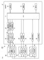
- FIG. 1 schematically shows a use state of the vital signs measurement apparatus 100 according to the first embodiment.
- FIG. 2 has shown the structural example of the vital sign measuring apparatus 100 shown in FIG.
- the vital sign measurement device 100 includes a device body 10, a cuff 20 for measuring blood pressure, a probe 30 for a pulse oximeter, and a chest piece 40 for a digital stethoscope.
- one or more electrodes 51, 52, 53, 54 for electrocardiogram measurement are attached to the cuff 20, the probe 30, and the chestpiece 40, respectively. Therefore, the vital sign measurement apparatus 100 according to the present embodiment can simultaneously measure vital signs such as blood pressure, blood oxygen saturation, pulse, heart sound, respiratory sound and electrocardiogram waveform of the subject.
- the apparatus body 10 has a CPU (central processing unit) 11, a storage unit 12, a display unit 13, and an operation unit 14 as basic functional blocks.
- the CPU 11 reads out the program stored in the storage unit 12 and controls the other elements according to this program and executes predetermined operations to control the entire vital sign measurement apparatus 100.
- the storage function of the storage unit 12 can be realized by non-volatile memory such as HDD and SDD, for example.
- the storage unit 12 may have a function as a memory for writing or reading progress of arithmetic processing by the CPU 11 or the like.
- the memory function of the storage unit 12 can be realized by a volatile memory such as a RAM or a DRAM.
- the display unit 13 is a display device such as a liquid crystal display or an organic EL display.
- the operation unit 14 includes input devices such as a mouse, a keyboard, a touch panel, and a microphone, and receives operation information by a person.
- the display unit 14 may be integrated with the operation unit 15 to constitute a touch panel display.
- the cuff 20 having the air bag 21 and the CPU 11, the pressure sensor 22, the oscillation circuit 23, the pump 24, the pump drive circuit 25, the exhaust valve 26, the valve drive circuit 27, and the air hose
- a sphygmomanometer is constituted by 28 and.
- the cuff 20 is a belt-like member used by being wound around a blood pressure measurement site of a subject, for example, an upper arm, and an air bladder 21 is provided inside thereof.
- the air bladder 21 is in communication with the pressure sensor 22, the pump 24 and the exhaust valve 26 via an air hose 28.
- the air bladder 21 is expanded by air being sent from the pump 24 into the internal space thereof, and is contracted by the air in the internal space being exhausted through the exhaust valve 26.
- the air pressure (cuff pressure) inside the air bladder 21 of the cuff 20 is detected by the pressure sensor 22.
- the pressure sensor 22 is, for example, a pressure-electric converter using a semiconductor pressure sensor, and is provided on the air hose 28.
- the pressure sensor 22 converts the air pressure (cuff pressure) of the air bladder 21 of the cuff 20 into an electrical signal, and the capacitance value changes with the cuff pressure.
- the oscillation circuit 23 outputs a signal (pressure signal) of an oscillation frequency corresponding to the capacitance value of the pressure sensor 22 to the CPU 11.
- the CPU 11 generates cuff pressure data based on the signal obtained from the oscillation circuit 23.
- the cuff pressure data indicates a cuff pressure waveform, and a pulse wave component or the like, which is a signal component representing a subject's pulse wave, is superimposed on the cuff pressure waveform at the time of blood pressure measurement.
- the CPU 100 Based on the cuff pressure data, the CPU 100 measures the lowest blood pressure and the highest blood pressure of the subject.
- the pump 24 increases the cuff pressure by supplying air to the air bladder 21 of the cuff 20 through the air hose 28.
- the pump drive circuit 25 outputs a drive signal to the pump 24 in accordance with a control signal from the CPU 11 to drive and control the pump 24, and starts and stops the supply of air from the pump 24 to the cuff 20.
- the exhaust valve 26 is, for example, an electromagnetic valve and is provided on the air hose 28.
- the exhaust valve 26 blocks the exhaust from the air bladder 21 of the cuff 20 when the valve is closed, while exhausting the air in the air bladder 21 of the cuff 20 through the air hose 28 when the valve is open.
- the valve drive circuit 27 controls the drive of the exhaust valve 26 in accordance with the control signal from the CPU 11, and adjusts the opening degree of the exhaust valve 26.
- the CPU 11 may generate control signals for the pump drive circuit 25 and the valve drive circuit 27 so as to measure the blood pressure by a general oscillometric method, and process the cuff pressure data obtained by the pressure sensor 22. Specifically, the CPU 11 sends air to the cuff 20, pressurizes the cuff pressure to press the blood vessel of the subject, and stops the blood flow. Thereafter, when the cuff pressure is gradually reduced, the pressure of the blood exceeds the pressure of the cuff, and from this time, the blood starts to flow intermittently in accordance with the heart beat (pulse).
- the vibration of the blood vessel wall synchronized with the pulse (pulse) of the heart is regarded as the fluctuation of the cuff pressure (pressure pulse wave).
- the CPU 11 measures the blood pressure value of the subject by measuring the variation amount of the cuff pressure at the timing coincident with the heartbeat of the heart.
- the cuff pressure when the pulse wave rapidly increases is referred to as "the highest blood pressure”
- the cuff pressure when the pulse wave rapidly decreases is referred to as the "minimum blood pressure”.
- a pulse oximeter is constituted by the probe 30 having the light emitting element 31 and the light receiving element 32, the CPU 11, the light emitting circuit 33 and the light receiving circuit 34 provided in the apparatus main body 10.
- Pulse oximeters use the principle that the light absorption characteristics of HbO 2 (hemoglobin containing oxygen) and Hb (hemoglobin not containing oxygen) in blood hemoglobin differ depending on the wavelength of light, and the probe or finger tip or ear
- the blood oxygen saturation SpO 2 is noninvasively measured by irradiating the living tissue with blood flow with light and detecting the light transmitted or reflected in the living tissue.
- the pulse oximeter it is possible to measure the subject's pulse simultaneously.
- the probe 30 includes a light emitting element 31 and a light receiving element 32, and these elements 31 and 32 are provided in a finger sack or the like attached to a finger tip or the like of a subject.
- An example of the light emitting element 31 is a light emitting diode.
- the light emitting element 31 is provided with at least two types, for example, one emitting red light and one emitting infrared light.
- the two light emitting elements 31 are alternately driven by the light emitting circuit 33 in the apparatus main body 10 at a predetermined cycle.
- a light receiving element 32 is disposed at a position facing the light emitting element 31 in the probe 30.
- An example of the light receiving element 32 is a silicon photodiode.
- the light receiving element 32 photoelectrically converts the light transmitted through the living tissue, and inputs an optical signal to the light receiving circuit 34 in the apparatus main body 10.
- the light receiving circuit 34 amplifies the light signal obtained from the light receiving element 32 and inputs it to the CPU 11.
- the CPU 11 controls the red light and the infrared light based on the changed AC component of the red light, the changed AC component of the infrared light, the unchanged DC component of the red light, and the unchanged DC component of the infrared light.
- the ratio of change ratio to light is determined, and the value of blood oxygen saturation (SpO 2 value) stored in advance in the storage unit 12 in accordance with the characteristics of the light emitting element 31 such as wavelength and half width linked to the ratio Read out. In this way, the blood oxygen saturation of the subject is measured.
- the CPU 11 can also measure the pulse rate per unit time of the subject based on the information such as the intensity change of the light signal.
- a digital stethoscope is constituted by the chest piece 40 having the microphone 41, the CPU 11 and the sound processing circuit 42 provided in the device main body 10.
- the chest piece 40 has a surface directly in contact with the measurement site (mainly the chest) of the subject, and has a structure for collecting heart sounds and breathing sounds.
- the chest piece 40 incorporates a microphone 41.
- the microphone 41 converts the sound (vibration) collected by the chest piece 40 into an acoustic signal (vibration signal) which is an electrical signal, and outputs this to the sound processing circuit 42 in the apparatus main body 10.
- the acoustic processing circuit 42 amplifies the acoustic signal, converts the analog signal into a digital signal, and performs filtering processing to correct the acoustic characteristic (frequency characteristic and phase characteristic) of the digitized acoustic signal. , Output to the CPU 11.
- the CPU 11 performs processing to determine whether or not the heart sound of the subject contains noise based on the acoustic signal obtained from the acoustic processing circuit 42, for example.
- a plurality of electrodes 51, 52, 53, 54 provided on each of the cuff 20, the probe 30, and the chest piece 40, and the CPU 11 and the electrocardiogram processing circuit 55 provided in the device body 10 The count is configured.
- the electrocardiograph measures an electrocardiogram recording the flow of electricity in the heart of a subject.
- the plurality of electrodes include, for example, a first electrocardiographic electrode 51, an indifferent electrode 52, a second electrocardiographic electrode 53, and a third electrocardiographic electrode 54.
- the first electrocardiogram electrode 51 and the indifferent electrode 52 are provided in a portion of the cuff 20 in contact with the skin of the subject.
- the second electrocardiogram electrode 53 is provided on a portion of the probe 30 in contact with the skin of the subject.
- the third electrode 40 is provided on a portion of the chestpiece 40 in contact with the skin of the subject.
- At least one electrocardiogram electrode 51 is provided on the cuff 20, and another electrocardiogram electrode 53 or 54 is provided on the other biomedical signal sensor (probe 30 or chest piece 40) to measure an electrocardiogram. is there.
- the cuff 20 is provided with the first electrocardiographic electrode 51 and the indifferent electrode 52, and the probe 30 is provided with the second electrocardiographic electrode 53, the third electrocardiographic electrode 54 of the chest piece 40 is omitted. It is also possible.
- the first to third electrocardiogram electrodes 51, 53, 54 are in contact with the measurement site of the human body and function as electrodes for detecting the body potential of the measurement site. Based on the electrocardiographic potentials obtained from the plurality of electrocardiogram electrodes 51, 53, 54, the potential difference at the measurement site can be derived.
- the indifferent electrode 52 functions as an electrode for removing extraneous noise induced in phase to the plurality of electrocardiogram electrodes 51, 53, 54.
- Each of the electrodes 51 to 54 is connected to an electrocardiogram processing circuit 55 in the apparatus main body 10.
- the electrocardiogram processing circuit 55 receives potential changes (body potential) derived from the respective electrocardiogram electrodes 51, 53, 54 and the indifferent electrode 52.
- the electrocardiogram processing circuit 55 differentially amplifies the body potential derived by each of the electrocardiogram electrodes 51, 53, 54, and removes extraneous noise by the potential derived from the indifferent electrode 52, thereby amplifying the amplified electrocardiogram signal ( Create an electrocardiogram waveform).
- the ECG signal may be generated by a bipolar induction method in which an electrocardiogram is generated with one pair of two electrodes, or three electrodes including an indifferent electrode are used. It may be a unipolar lead method of creating an electrocardiogram between the separated electrodes.
- the amplified electrocardiogram signal is input to the CPU 11.
- the CPU 11 analog-digital converts the electrocardiogram signal input from the electrocardiogram processing circuit 55, performs data compression and other signal processing on the electrocardiogram signal as necessary, and stores the processed electrocardiogram signal Record at 12.
- At least one electrocardiographic electrode 51 is provided on the cuff 20, and another electrocardiographic electrode paired with this is provided on another biosignal sensor.
- the first electrocardiographic electrode 51 and the probe 30 provided on the cuff 20 An electrocardiogram signal can be created based on the potential difference of the second electrocardiogram electrode 53 provided on the According to such a configuration, the distance between the first electrocardiogram electrode 51 and the second electrocardiogram electrode 53 can be sufficiently long, so that the accuracy of the electrocardiogram signal can be improved.
- I induction can be observed, which is also useful for detection of arrhythmia.
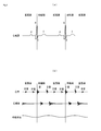
- FIG. 3 shows an example of an electrocardiogram obtained based on the electrodes 51-54.
- the electrocardiogram includes P wave, Q wave, R wave, S wave and T wave, and the period from the peak of R wave to the end of T wave is the systole of the heart and the other period is the expansion of the heart It becomes a period.
- FIG. 3 (b) shows an example of sounds around the heart detected by the microphone 41.
- a heart sound is a sound generated along with the beating of the heart and generates I sound, II sound, III sound, and IV sound. Of these sounds, sound I occurs immediately after the onset of systole of the heart, and sound II occurs at the boundary between systole and diastole.
- Heart noise is a sound that occurs with the heartbeat but does not occur in a normal heart. Breathing sound is a normal sound produced by internal activity such as breathing, apart from the heart. Since the microphone 41 converts sounds in which heart sounds, heart noises, breathing sounds and the like overlap into electric signals, the sound signals received by the CPU 11 include those in which sounds around the heart are overlapped in multiple layers.
- the CPU 11 extracts the systole of the heart based on the electrocardiogram signal acquired from each of the electrodes 51-54. Specifically, R wave and T wave are extracted from the electrocardiogram shown in FIG. 3A, and the period from the peak of R wave to the end of T wave is defined as systole. However, since the II sound is generated at the end of the T wave, it is preferable to set the time from the end of the T wave to the end of the systole so that the II sound is not included. Then, the CPU 11 determines whether or not there is cardiac noise in the extracted systole.
- the CPU 11 detects whether there is a sound with an amplitude exceeding a predetermined threshold from 0.3 seconds after the onset of systole to the end of the systole.
- the threshold value can be appropriately set, such as obtained from the amplitude of the I sound, or using an absolute value obtained in an experiment or the like.
- the reason for determining from 0.3 seconds after the onset of systole is to exclude time until the I sound is sufficiently large as the sound at the beginning of the systole, so that it will be sufficiently small. Since this time is influenced by the pulse rate, it is not limited to 0.3 seconds, and may be changed as appropriate, and may be varied according to the pulse rate.
- the CPU 11 records the generation timing within the systole. Then, the CPU 11 determines that there is a cardiac noise if there is a sound exceeding the threshold at the same timing at all times after performing detection in consecutive (for example, 10 times) systole cycles.
- the determination based on a plurality of systoles is to eliminate the influence of noise such as respiratory sound, and the influence of respiratory sound can be eliminated by measuring, for example, about 10 times from the timing of respiration. The number of times is not limited to 10 and may be changed as appropriate.
- the criterion that there is a sound that exceeds the threshold in all 10 systoles is also an example. Judgment condition is also suitably changed such that it is determined that there is cardiac noise even if it exceeds the threshold of less than 10 times. be able to.
- an electrocardiogram signal measured by an electrocardiograph can be used to increase the accuracy of blood pressure measurement by the sphygmomanometer.
- the CPU 11 receives an electrocardiogram signal generated based on the body potential difference detected by each of the electrodes 51 to 54. Then, the pulse wave of the subject is extracted from the electrocardiogram signal. Specifically, the systole of the heart (the period from the peak of the R wave to the end of the T wave is the systole of the heart: see FIG. 3A) is extracted.
- the CPU 11 controls the pump 24 to pressurize the cuff pressure in the cuff and then depressurizes the exhaust valve 26 to measure the systolic and diastolic blood pressure of the subject in the process from pressurization to depressurization.
- the cardiac systole is not The blood pressure may be minimized at the timing of These systolic and diastolic timings other than the systole of the heart do not accurately indicate the blood pressure value of the subject.
- the CPU 11 ignores (cancels) the systolic blood pressure and the diastolic blood pressure at timings other than the cardiac systole, and measures the systolic blood pressure and the diastolic blood pressure detected within the systolic period of the heart.
- it becomes possible to improve the accuracy of the automatic blood pressure monitor by accurately grasping the timing of the pulse wave of the subject from the electrocardiogram and acquiring the systolic blood pressure and the diastolic blood pressure at the timing coincident with the pulsation. .
- the probe 30 and the chestpiece 40 when adopted as biological signal sensors for measuring vital signs, it is preferable that the probe 30 and the chestpiece 40 have a mechanism which can be detachably combined.
- the probe 30 and the chest piece 40 may be combined by a physical structure such as fitting to one and the other, or may be combined by magnetic force by attaching permanent magnets to both. Good. In this way, for example, as shown in FIG. 1, it becomes easy to hold the probe 30 and the chest piece 40 with one hand. Also, the probe 30 and the chestpiece 40 can be separated and used according to the usage scene.
- thermometer (not shown) for measuring a subject's body temperature instead of this or together with this May be adopted.
- one or more electrodes for electrocardiogram measurement are provided at a portion of the thermometer that comes in contact with the skin of the subject.
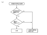
- FIG. 4 shows an example of an automatic diagnosis flow of aortic valve stenosis.
- the CPU of the device main body 10 distinguishes the systole and diastole time zones of the subject's heart from the electrocardiogram, and obtains the difference in the blood pressure of the subject in the systole and diastole (that is, "pulse pressure") .
- pulse pressure the difference in the blood pressure of the subject in the systole and diastole.
- cardiac murmur is observed during systole, it is highly suspected of suffering from aortic valve stenosis. In this disease, as the symptoms get worse, cardiac noise during systole increases, but when it progresses further, cardiac noise during systole tends to be weaker.
- patients suffering from late-stage aortic stenosis tend to have lower pulse pressure. Therefore, by measuring pulse pressure simultaneously with cardiac noise during systole, even severe aor
- the systolic noise when the systolic noise is below a certain threshold and the pulse pressure is above a certain threshold, it is diagnosed as normal. On the other hand, if the systolic noise exceeds a certain threshold, it is diagnosed as having suspicion of aortic valve stenosis. In addition, even if the systolic noise is below a certain threshold, if the pulse pressure does not reach a certain threshold, it is diagnosed that aortic valve stenosis is suspected.
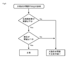
- FIG. 5 shows an example of an automatic diagnosis flow of aortic valve insufficiency.
- the CPU of the device main body 10 distinguishes the systole and diastole time zones of the subject's heart from the electrocardiogram, and obtains the difference in the blood pressure of the subject in the systole and diastole (that is, "pulse pressure") . If cardiac murmur is noted during diastole, you are more likely to have aortic regurgitation. In this disease, the cardiac noise in diastole increases as the symptoms get worse, but when it progresses further, the cardiac noise in diastole tends to be rather weak.
- the diastolic noise when the diastolic noise is less than a certain threshold and the pulse pressure is less than a certain threshold, it is diagnosed as normal. On the other hand, if diastolic noise exceeds a certain threshold, it is diagnosed as having aortic valve insufficiency. Also, even if the diastolic noise is below a certain threshold, if the pulse pressure exceeds a certain threshold, it is diagnosed as having a suspected aortic valve insufficiency.
- the threshold of systolic noise and the threshold of pulse pressure may be adjusted as appropriate.
Landscapes
- Health & Medical Sciences (AREA)
- Life Sciences & Earth Sciences (AREA)
- Physics & Mathematics (AREA)
- General Health & Medical Sciences (AREA)
- Veterinary Medicine (AREA)
- Engineering & Computer Science (AREA)
- Biomedical Technology (AREA)
- Heart & Thoracic Surgery (AREA)
- Medical Informatics (AREA)
- Molecular Biology (AREA)
- Surgery (AREA)
- Animal Behavior & Ethology (AREA)
- Biophysics (AREA)
- Public Health (AREA)
- Pathology (AREA)
- Cardiology (AREA)
- Vascular Medicine (AREA)
- Physiology (AREA)
- Ophthalmology & Optometry (AREA)
- Pulmonology (AREA)
- Spectroscopy & Molecular Physics (AREA)
- Optics & Photonics (AREA)
- Measuring Pulse, Heart Rate, Blood Pressure Or Blood Flow (AREA)
- Measurement Of The Respiration, Hearing Ability, Form, And Blood Characteristics Of Living Organisms (AREA)
- Measurement And Recording Of Electrical Phenomena And Electrical Characteristics Of The Living Body (AREA)
Priority Applications (2)
| Application Number | Priority Date | Filing Date | Title |
|---|---|---|---|
| US16/616,492 US20200297225A1 (en) | 2017-08-29 | 2018-08-29 | Vital sign measurement device |
| CN201880026776.7A CN112040851A (zh) | 2017-08-29 | 2018-08-29 | 生命体征测量装置 |
Applications Claiming Priority (2)
| Application Number | Priority Date | Filing Date | Title |
|---|---|---|---|
| JP2017163947A JP6535060B2 (ja) | 2017-08-29 | 2017-08-29 | バイタルサイン測定装置 |
| JP2017-163947 | 2017-08-29 |
Publications (1)
| Publication Number | Publication Date |
|---|---|
| WO2019044876A1 true WO2019044876A1 (ja) | 2019-03-07 |
Family
ID=65527494
Family Applications (1)
| Application Number | Title | Priority Date | Filing Date |
|---|---|---|---|
| PCT/JP2018/031884 Ceased WO2019044876A1 (ja) | 2017-08-29 | 2018-08-29 | バイタルサイン測定装置 |
Country Status (4)
| Country | Link |
|---|---|
| US (1) | US20200297225A1 (https=) |
| JP (1) | JP6535060B2 (https=) |
| CN (1) | CN112040851A (https=) |
| WO (1) | WO2019044876A1 (https=) |
Cited By (2)
| Publication number | Priority date | Publication date | Assignee | Title |
|---|---|---|---|---|
| CN110384496A (zh) * | 2019-07-24 | 2019-10-29 | 刘阳 | 一种可穿戴多参测量仪 |
| WO2024117133A1 (ja) * | 2022-12-01 | 2024-06-06 | テルモ株式会社 | バイタル測定装置、バイタル測定方法、及びバイタル測定システム |
Citations (9)
| Publication number | Priority date | Publication date | Assignee | Title |
|---|---|---|---|---|
| JPS63252136A (ja) * | 1987-04-10 | 1988-10-19 | 武内 克郎 | 心雑音自動診断装置 |
| JPH07163528A (ja) * | 1992-01-29 | 1995-06-27 | Hewlett Packard Co <Hp> | 生命徴候情報を収集し、監視する方法とそのシステム |
| JP2000237149A (ja) * | 1999-02-25 | 2000-09-05 | Matsushita Electric Works Ltd | 健康測定機器 |
| JP2002000576A (ja) * | 2000-06-22 | 2002-01-08 | Omron Corp | 生体情報計測センサ |
| JP2003024310A (ja) * | 2001-07-11 | 2003-01-28 | Seiko Epson Corp | 無酸素性作業閾値検出装置 |
| JP2005168600A (ja) * | 2003-12-08 | 2005-06-30 | Nippon Koden Corp | バイタルテレメータ |
| JP2005523066A (ja) * | 2002-04-19 | 2005-08-04 | コーリンメディカルテクノロジー株式会社 | 末梢部位の心音信号の記録のための方法と装置 |
| US20110208015A1 (en) * | 2009-07-20 | 2011-08-25 | Masimo Corporation | Wireless patient monitoring system |
| JP2015511840A (ja) * | 2012-02-09 | 2015-04-23 | マシモ コーポレーションMasimo Corporation | ワイヤレス患者監視デバイス |
Family Cites Families (3)
| Publication number | Priority date | Publication date | Assignee | Title |
|---|---|---|---|---|
| US20040267145A1 (en) * | 1999-07-21 | 2004-12-30 | Daniel David | Physiological measuring system comprising a garment in the form of a sleeve or glove and sensing apparatus incorporated in the garment |
| KR101040598B1 (ko) * | 2008-07-07 | 2011-06-10 | 주식회사 바이오넷 | 벨트형 센서와 커프를 이용한 혈압 측정장치 |
| US9408542B1 (en) * | 2010-07-22 | 2016-08-09 | Masimo Corporation | Non-invasive blood pressure measurement system |
-
2017
- 2017-08-29 JP JP2017163947A patent/JP6535060B2/ja active Active
-
2018
- 2018-08-29 US US16/616,492 patent/US20200297225A1/en not_active Abandoned
- 2018-08-29 WO PCT/JP2018/031884 patent/WO2019044876A1/ja not_active Ceased
- 2018-08-29 CN CN201880026776.7A patent/CN112040851A/zh active Pending
Patent Citations (9)
| Publication number | Priority date | Publication date | Assignee | Title |
|---|---|---|---|---|
| JPS63252136A (ja) * | 1987-04-10 | 1988-10-19 | 武内 克郎 | 心雑音自動診断装置 |
| JPH07163528A (ja) * | 1992-01-29 | 1995-06-27 | Hewlett Packard Co <Hp> | 生命徴候情報を収集し、監視する方法とそのシステム |
| JP2000237149A (ja) * | 1999-02-25 | 2000-09-05 | Matsushita Electric Works Ltd | 健康測定機器 |
| JP2002000576A (ja) * | 2000-06-22 | 2002-01-08 | Omron Corp | 生体情報計測センサ |
| JP2003024310A (ja) * | 2001-07-11 | 2003-01-28 | Seiko Epson Corp | 無酸素性作業閾値検出装置 |
| JP2005523066A (ja) * | 2002-04-19 | 2005-08-04 | コーリンメディカルテクノロジー株式会社 | 末梢部位の心音信号の記録のための方法と装置 |
| JP2005168600A (ja) * | 2003-12-08 | 2005-06-30 | Nippon Koden Corp | バイタルテレメータ |
| US20110208015A1 (en) * | 2009-07-20 | 2011-08-25 | Masimo Corporation | Wireless patient monitoring system |
| JP2015511840A (ja) * | 2012-02-09 | 2015-04-23 | マシモ コーポレーションMasimo Corporation | ワイヤレス患者監視デバイス |
Cited By (3)
| Publication number | Priority date | Publication date | Assignee | Title |
|---|---|---|---|---|
| CN110384496A (zh) * | 2019-07-24 | 2019-10-29 | 刘阳 | 一种可穿戴多参测量仪 |
| CN110384496B (zh) * | 2019-07-24 | 2021-10-08 | 湖南可孚芯驰医疗科技有限公司 | 一种可穿戴多参测量仪 |
| WO2024117133A1 (ja) * | 2022-12-01 | 2024-06-06 | テルモ株式会社 | バイタル測定装置、バイタル測定方法、及びバイタル測定システム |
Also Published As
| Publication number | Publication date |
|---|---|
| CN112040851A (zh) | 2020-12-04 |
| JP6535060B2 (ja) | 2019-06-26 |
| JP2019037686A (ja) | 2019-03-14 |
| US20200297225A1 (en) | 2020-09-24 |
Similar Documents
| Publication | Publication Date | Title |
|---|---|---|
| US20210030372A1 (en) | Methods to estimate the blood pressure and the arterial stiffness based on photoplethysmographic (ppg) signals | |
| CN101264011B (zh) | 无箍带无侵入地测量腕部血压的方法和装置 | |
| Shriram et al. | Continuous cuffless blood pressure monitoring based on PTT | |
| Chen et al. | Noninvasive monitoring of blood pressure using optical Ballistocardiography and Photoplethysmograph approaches | |
| WO2018113442A1 (zh) | 一种基于脉搏波传导的连续动态血压监测装置和方法 | |
| US20140378849A1 (en) | Method and apparatus to monitor physiologic and biometric parameters using a non-invasive set of transducers | |
| CN105708431A (zh) | 血压实时测量装置及测量方法 | |
| EA013620B1 (ru) | Мобильный диагностический прибор | |
| Tavakolian et al. | Improvement of ballistocardiogram processing by inclusion of respiration information | |
| Das et al. | Noninvasive accelerometric approach for cuffless continuous blood pressure measurement | |
| US9161699B2 (en) | Device for the non-invasive determination of arterial blood pressure | |
| Taha et al. | A review on non-invasive hypertension monitoring system by using photoplethysmography method | |
| JP2024516573A (ja) | 生理学パラメータ検知システム及び方法 | |
| JP6535060B2 (ja) | バイタルサイン測定装置 | |
| CN106073735A (zh) | 一种用于连续检测人体血压的集成电路结构 | |
| CN111345791A (zh) | 一种脉搏波测量装置 | |
| GB2520487A (en) | Blood-flow sensor apparatus | |
| Hoseinzadeh et al. | Design and Implementation of a blood pressure device with high sampling frequency to analyze cardiovascular diseases in LabVIEW | |
| Wu et al. | Automatic estimation of respiratory rate from pulse transit time in normal subjects at rest | |
| JP7670536B2 (ja) | 脈波解析装置、脈波解析方法、および脈波解析プログラム | |
| Alam et al. | Portable photoplethysmogram acquisition and analysis instrument | |
| JP2019037686A5 (https=) | ||
| CN223586208U (zh) | 非接触式智能监护牙椅 | |
| Choudhary et al. | Vibrocarotidography: A novel measurement technique to quantify pulsations at common carotid arteries | |
| Jayasree et al. | Design and development of a simple hardware setup for sensing blood volume pulse and a PIC microcontroller based heart rate meter |
Legal Events
| Date | Code | Title | Description |
|---|---|---|---|
| 121 | Ep: the epo has been informed by wipo that ep was designated in this application |
Ref document number: 18850464 Country of ref document: EP Kind code of ref document: A1 |
|
| DPE1 | Request for preliminary examination filed after expiration of 19th month from priority date (pct application filed from 20040101) | ||
| NENP | Non-entry into the national phase |
Ref country code: DE |
|
| 122 | Ep: pct application non-entry in european phase |
Ref document number: 18850464 Country of ref document: EP Kind code of ref document: A1 |