WO2019044594A1 - Photoacoustic image generation device and image acquisition method - Google Patents
Photoacoustic image generation device and image acquisition method Download PDFInfo
- Publication number
- WO2019044594A1 WO2019044594A1 PCT/JP2018/030838 JP2018030838W WO2019044594A1 WO 2019044594 A1 WO2019044594 A1 WO 2019044594A1 JP 2018030838 W JP2018030838 W JP 2018030838W WO 2019044594 A1 WO2019044594 A1 WO 2019044594A1
- Authority
- WO
- WIPO (PCT)
- Prior art keywords
- photoacoustic
- excitation light
- image
- photoacoustic image
- subject
- Prior art date
Links
Images

Classifications
-
- A—HUMAN NECESSITIES
- A61—MEDICAL OR VETERINARY SCIENCE; HYGIENE
- A61B—DIAGNOSIS; SURGERY; IDENTIFICATION
- A61B8/00—Diagnosis using ultrasonic, sonic or infrasonic waves
- A61B8/13—Tomography
Definitions
- the present invention generates a photoacoustic image based on a signal obtained by detecting a photoacoustic wave generated from the inside of a subject by receiving excitation light emitted toward the subject from a light source.
- the present invention relates to an apparatus and an image acquisition method in a photoacoustic image generation apparatus.
- pulsed light having a certain appropriate wavelength for example, wavelength band of visible light, near infrared light or mid-infrared light
- the photoacoustic wave which is an elastic wave generated as a result of absorption of light energy, is detected to quantitatively measure the concentration of the absorbing substance.
- Absorbent substances in a subject are, for example, blood vessels, glucose and hemoglobin contained in blood, and the like.
- a technology for detecting such photoacoustic waves and generating a photoacoustic image based on the detection signal is called photoacoustic imaging (PAI) or photoacoustic tomography (PAT). ing.
- PAI photoacoustic imaging
- PAT photoacoustic tomography
- Patent Documents 1 and 2 show an apparatus for performing photoacoustic imaging to generate a photoacoustic image.
- This type of photoacoustic image generating apparatus is often configured to be able to generate a so-called reflected ultrasonic image.
- an apparatus for generating a reflected ultrasound image is a subject based on a signal obtained by detecting a reflected acoustic wave that an acoustic wave (mostly an ultrasonic wave) emitted toward a subject is reflected in the subject. Generate a tomographic image etc. inside the sample.
- a photoacoustic image generating apparatus generally emits excitation light such as laser light toward a subject, and detects a photoacoustic wave generated from a portion that has absorbed the excitation light, based on a signal obtained. A photoacoustic image showing an internal tissue or the like of a subject is generated.
- the photoacoustic wave can be efficiently received by the ultrasonic probe by optimizing the pulse width of the excitation light for generating the photoacoustic wave according to the ultrasonic probe. It is disclosed that
- An object of the present invention is to provide a photoacoustic image generation device in which the visible depth in a photoacoustic image is improved and an image acquisition method in the photoacoustic image generation device.
- the photoacoustic image generating apparatus is based on a signal obtained by detecting photoacoustic waves generated from the inside of the subject by receiving excitation light emitted from the light source toward the subject by the acoustic wave detection unit.
- the photoacoustic image generation apparatus including the photoacoustic image generation unit that generates the photoacoustic image, the light source is determined based on the reception frequency characteristic of the acoustic wave detection unit and the attenuation characteristic of the photoacoustic wave in the object.
- a control unit that performs control to adjust the excitation light generation condition based on the pulse width of the excitation light generated in
- the control unit stores a plurality of excitation light generation conditions having different frequency characteristics of the photoacoustic wave generated in the subject, and among the plurality of excitation light generation conditions stored.
- the light source may be controlled based on the excitation light generation condition selected from the above.
- control unit stores a plurality of excitation light generation conditions for each type of acoustic wave detection means having different reception frequency characteristics, and the excitation light selected by the user from among the plurality of stored excitation light generation conditions
- the light source may be controlled based on the generation condition.
- the control unit may adjust the excitation light generation condition based on the image depth of the photoacoustic image.
- control unit may adjust the excitation light generation condition based on the focal depth of the photoacoustic image.
- the photoacoustic image generation unit may perform correction processing on the photoacoustic image based on the excitation light generation condition.
- the image acquisition method is a method for detecting an optical signal generated from the inside of a subject by receiving excitation light emitted toward the subject from a light source by means of an acoustic wave detection unit.
- An image acquisition method in a photoacoustic image generation apparatus comprising a photoacoustic image generation unit for generating an acoustic image, wherein a reception frequency characteristic of the acoustic wave detection unit and an attenuation characteristic of the photoacoustic wave in the object are Based on the control, control is performed to adjust the excitation light generation condition based on the pulse width of the excitation light generated in the light source.
- the light source may be controlled based on the light generation condition.
- a plurality of excitation light generation conditions are stored for each type of reception frequency characteristics of the acoustic wave detection means different, and based on the excitation light generation conditions selected by the user from among the plurality of stored excitation light generation conditions.
- the light source may be controlled.
- the excitation light generation condition may be adjusted based on the image depth of the photoacoustic image.
- the excitation light generation condition may be adjusted based on the focal depth of the photoacoustic image.
- correction process may be performed on the photoacoustic image based on the excitation light generation condition.
- the excitation light generated in the light source is generated based on the reception frequency characteristic of the acoustic wave detecting means and the attenuation characteristic of the photoacoustic wave in the object. Since the control for adjusting the excitation light generation condition based on the pulse width of the pulse is performed, the reception efficiency of the photoacoustic wave in the acoustic wave detection means can be improved, and as a result, the visible depth in the photoacoustic image Can be improved.
- a block diagram showing a schematic configuration of a photoacoustic image generation apparatus according to an embodiment of the present invention Graph showing spectrum of photoacoustic wave
- FIG. 1 is a schematic view showing the overall configuration of a photoacoustic image generation apparatus 10 according to an embodiment of the present invention.
- the shape of the ultrasonic probe (hereinafter simply referred to as a probe) 11 is schematically shown.
- the photoacoustic image generation apparatus 10 of this example has a function of generating a photoacoustic image based on a photoacoustic wave detection signal, and as schematically shown in FIG. 1, the probe 11, the ultrasound unit 12, The laser unit 13, the image display unit 14, and the input unit 15 are provided.
- those components will be sequentially described.
- the probe 11 as an acoustic wave detection means has a function of emitting excitation light and an ultrasonic wave toward the subject M which is a living body, for example, and a function of detecting the acoustic wave U propagating in the subject M. That is, the probe 11 performs emission (transmission) of ultrasonic waves (acoustic waves) to the subject M and detection (reception) of reflected ultrasonic waves (reflection acoustic waves) reflected back from the subject M. it can.
- acoustic wave as used herein is a term including ultrasonic waves and photoacoustic waves.
- ultrasonic wave means an elastic wave transmitted by the probe 11 and its reflected wave (reflected ultrasonic wave)
- photoacoustic wave is an elasticity emitted by the absorber 65 absorbing the excitation light. Means a wave.
- the acoustic wave emitted by the probe 11 is not limited to the ultrasonic wave, and the acoustic wave of the audio frequency may be used as long as an appropriate frequency is selected according to the test object, the measurement condition, etc. .
- the absorber 65 in the subject M for example, blood vessels, glucose and hemoglobin contained in blood, and the like, and further metal members and the like can be mentioned.
- probes 11 corresponding to sector scanning, linear scanning and convex scanning are prepared, and an appropriate probe is selected and used from among them depending on the imaging site. Further, the probe 11 is connected to an optical fiber 60 as a connection unit for guiding a laser beam L, which is excitation light emitted from a laser unit 13 described later, to the light emitting unit 40.
- the probe 11 includes a transducer array 20 which is an acoustic wave detector, and a total of two light emitting portions 40 disposed one on each side of the transducer array 20 with the transducer array 20 interposed therebetween. And a case 50 in which the transducer array 20, the two light emitting units 40, and the like are accommodated.
- the transducer array 20 also functions as an ultrasonic transmission element.
- the transducer array 20 is connected to an ultrasonic transmission control circuit 35, a receiving circuit 21 and the like via a wire not shown.
- the transducer array 20 is formed by arranging a plurality of acoustic transducers (ultrasonic transducers), which are electroacoustic transducers, in one-dimensional direction.
- the acoustic wave vibrator is a piezoelectric element made of, for example, piezoelectric ceramic.
- the acoustic wave vibrator may be a piezoelectric element made of a polymer film such as polyvinylidene fluoride (PVDF).
- PVDF polyvinylidene fluoride
- the acoustic wave transducer has a function of converting the received acoustic wave U into an electrical signal.
- the transducer array 20 may include an acoustic lens.
- the transducer array 20 in the present embodiment is formed by arranging a plurality of acoustic wave transducers one-dimensionally in parallel, but a vibration in which a plurality of acoustic wave transducers are arranged two-dimensionally.
- a child array may be used.
- the acoustic wave transducer also has a function of transmitting an ultrasonic wave as described above. That is, when an alternating voltage is applied to the acoustic wave transducer, the acoustic wave transducer generates an ultrasonic wave of a frequency corresponding to the frequency of the alternating voltage.
- the transmission and reception of ultrasonic waves may be separated from each other. That is, for example, ultrasonic waves may be transmitted from a position different from that of the probe 11, and the reflected ultrasonic waves to the transmitted ultrasonic waves may be received by the probe 11.
- the light emitting unit 40 is a portion that emits the laser light L guided by the optical fiber 60 toward the subject M.
- the light emitting unit 40 is constituted by the tip of the optical fiber 60, that is, the end far from the laser unit 13 which is the light source of the excitation light.
- two light emitting portions 40 are disposed on both sides, for example, in the elevation direction of the transducer array 20 with the transducer array 20 interposed therebetween.
- the elevation direction is a direction parallel to the detection surface of the transducer array 20 at right angles to the alignment direction when a plurality of acoustic wave transducers are arranged in one dimension.
- the light emitting portion may be configured of a light guide plate and a diffusion plate optically coupled to the tip of the optical fiber 60.
- a light guide plate can be made of, for example, an acrylic plate or a quartz plate.
- the diffusion plate a lens diffusion plate in which microlenses are randomly disposed on the substrate can be used.
- a quartz plate in which diffusion particles are dispersed can be used.
- a holographic diffusion plate may be used, or an engineering diffusion plate may be used.
- the laser unit 13 as a light source includes, for example, a flash lamp pumped Q-switched solid-state laser such as a Q-switched alexandrite laser, and generates laser light L as pumped light.
- the laser unit 13 is configured to output a laser beam L in response to a trigger signal from the control unit 30 of the ultrasonic unit 12.
- the wavelength of the laser beam L is appropriately selected according to the light absorption characteristic of the absorber 65 in the subject M to be measured.
- the wavelength is preferably a wavelength belonging to the near infrared wavelength range.
- the near infrared wavelength range means a wavelength range of approximately 700 to 2500 nm (nanometers).
- the wavelength of the laser light L is of course not limited to this.
- the laser light L may be of a single wavelength or may include multiple wavelengths such as 750 nm (nanometers) and 800 nm (nanometers). When the laser beam L includes a plurality of wavelengths, the light of these wavelengths may be emitted simultaneously or may be emitted while switching alternately.
- the laser unit 13 can also output YAG (Yttrium Aluminum Garnet: Yttrium Aluminum Garnet) -SHG (Second Harmonic Generation), which can output laser light in the near-infrared wavelength region as well as the alexandrite laser described above.
- Second harmonic generation)-OPO (Optical Parametric Osillation) laser or Ti-Sapphire (titanium-sapphire) laser can also be used.
- the laser unit 13 can also be configured using a LD (Laser Diode) or an LED (Light Emitting Diode). Since the present invention improves the reception efficiency of photoacoustic waves, the light source can be a low power LD or LED instead of a high power individual laser. In addition, in order to generate excitation light of an arbitrary waveform as described later, LD or LED is generally preferable to a solid laser.
- LD Laser Diode
- LED Light Emitting Diode
- the optical fiber 60 guides the laser light L emitted from the laser unit 13 to the two light emitting portions 40.
- the optical fiber 60 is not particularly limited, and a known fiber such as a quartz fiber can be used.
- a known fiber such as a quartz fiber can be used.
- one thick optical fiber may be used, or a bundle fiber in which a plurality of optical fibers are bundled may be used.
- the bundle fiber is disposed such that the laser beam L is incident from the light incident end face of the combined fiber portion, and the fiber portion branched into two of the bundle fiber Each tip constitutes the light emitting unit 40 as described above.
- the ultrasound unit 12 includes a reception circuit 21, a reception memory 22, an image generation unit 26, an image output unit 27, a control unit 30, and a transmission control circuit 35.
- the image generation unit 26 includes a data separation unit 23, a photoacoustic image generation unit 24, and an ultrasound image generation unit 25.
- the control unit 30 controls the laser unit 13 as the light source to adjust the excitation light generation condition based on the pulse width of the laser light L generated in the laser unit 13 based on the reception frequency characteristic of the probe 11 And other functions.
- the ultrasound unit 12 typically includes a processor, a memory, a bus, and the like.
- programs relating to photoacoustic image generation processing, ultrasound image generation processing, control processing for the laser unit 13, and the like are incorporated in a memory (not shown).
- the program is operated by the control unit 30 configured by a processor to realize the function of each unit. That is, these units are configured by a memory and a processor in which a program is incorporated.
- the hardware configuration of the ultrasound unit 12 is not particularly limited, and a plurality of integrated circuits (ICs), processors, application specific integrated circuits (ASICs), field-programmable gate arrays (FPGAs), memories, etc. It can be realized by appropriately combining
- the receiving circuit 21 receives the detection signal output from the probe 11, and stores the received detection signal in the receiving memory 22.
- the receiving circuit 21 typically includes a low noise amplifier, a variable gain amplifier, a low pass filter, and an analog to digital converter.
- the detection signal of the probe 11 is amplified by a low noise amplifier, then gain adjusted according to the depth by a variable gain amplifier, high frequency components are cut by a low pass filter, and then converted to digital signals by an AD converter It is stored in the memory 22.
- the receiving circuit 21 is configured of, for example, one IC.
- the probe 11 outputs a detection signal of the photoacoustic wave and a detection signal of the reflected ultrasonic wave
- the reception memory 22 stores detection signals (sampling data) of the photoacoustic wave and the reflected ultrasonic wave subjected to AD conversion.
- the data separation unit 23 reads the detection signal of the photoacoustic wave from the reception memory 22 and transmits the detection signal to the photoacoustic image generation unit 24. Further, the detection signal of the reflected ultrasound is read from the reception memory 22 and transmitted to the ultrasound image generation unit 25.
- the photoacoustic image generation unit 24 generates a photoacoustic image based on the detection signal of the photoacoustic wave detected by the probe 11.
- the photoacoustic image generation process includes, for example, image reconstruction such as phase matching addition, detection, logarithmic conversion, and the like.
- the ultrasound image generation unit 25 generates an ultrasound image based on the detection signal of the reflected ultrasound detected by the probe 11.
- the ultrasonic image generation process also includes image reconstruction such as phase matching addition, detection, logarithmic conversion, and the like.
- the image output unit 27 outputs the photoacoustic image and / or the ultrasound image to an image display unit 14 such as a display device.
- the control unit 30 controls each unit in the ultrasonic unit 12.
- the control unit 30 transmits a trigger signal to the laser unit 13 based on excitation light generation conditions described later, and causes the laser unit 13 to emit the laser light L.
- a sampling trigger signal is transmitted to the receiving circuit 21 to control the sampling start timing of the photoacoustic wave and the like.
- the sampling data received by the receiving circuit 21 is stored in the receiving memory 22.
- the photoacoustic image generation unit 24 receives the sampling data of the detection signal of the photoacoustic wave via the data separation unit 23, and detects it at a predetermined detection frequency to generate a photoacoustic image.
- the photoacoustic image generated by the photoacoustic image generation unit 24 is input to the image output unit 27.
- the control unit 30 transmits an ultrasonic wave transmission trigger signal indicating that the ultrasonic wave transmission is instructed to the transmission control circuit 35.
- the transmission control circuit 35 causes the probe 11 to transmit an ultrasonic wave when receiving the ultrasonic wave transmission trigger signal.
- the probe 11 scans the reception area of the piezoelectric element group while shifting, for example, one line at a time under the control of the control unit 30, and detects a reflected ultrasonic wave.
- the control unit 30 transmits a sampling trigger signal to the receiving circuit 21 in accordance with the timing of ultrasonic wave transmission, and starts sampling of reflected ultrasonic waves.
- the sampling data received by the receiving circuit 21 is stored in the receiving memory 22.
- the ultrasonic image generation unit 25 receives sampling data of a detection signal of ultrasonic waves through the data separation unit 23, detects the data at a predetermined detection frequency, and generates an ultrasonic image.
- the ultrasound image generated by the ultrasound image generation unit 25 is input to the image output unit 27.
- the control unit 30 controls the laser unit 13 (light source) based on the reception frequency characteristic of the probe 11 (acoustic wave detection means) and the attenuation characteristic of the photoacoustic wave in the subject M. Control is performed to adjust the excitation light generation condition based on the pulse width of the laser light L (excitation light) generated in the laser unit 13.
- a center frequency is considered as a frequency characteristic here, it is good also as other frequency characteristics, such as peak frequency.
- Ultrasonic waves have different attenuation rates depending on the type of tissue of a subject. Specifically, the attenuation is low in tissues containing a large amount of water, whereas the attenuation is large in tissues containing a large amount of calcium or fat. Further, even in the same tissue, the longer the ultrasonic wave (photoacoustic wave) transmission distance (the deeper the observation target depth), the larger the attenuation. Therefore, when adjusting the excitation light generation condition based on the attenuation characteristic of the photoacoustic wave in the subject M, the excitation light generation condition is adjusted based on both the type of the tissue of the subject M and the depth of the observation target. The excitation light generation conditions may be adjusted based on either one. Here, the case of adjusting the excitation light generation condition based on only the depth of the observation target will be described.
- pulse width t LP 77 ns (nanoseconds) of the laser light L
- FIG. 2 which is a graph showing the spectrum of the photoacoustic wave
- the center frequency of the photoacoustic wave immediately before 11 changes from 6.5 MHz (megahertz) to a lower center frequency.
- the reception frequency band of the probe 11 is a band having a width of 70% to 100% with respect to the center frequency
- the frequency of acoustic waves that can be received by the probe 11 with a center frequency of 6.5 MHz (megahertz) is 3.. It is considered to be about 2 to 9.8 MHz (megahertz). Therefore, in the present embodiment, in consideration of attenuation in the subject M, the center frequency of the photoacoustic wave immediately before the probe 11 is a frequency that can be received by the probe 11 having a center frequency of 6.5 MHz (megahertz).
- the excitation light generation conditions are adjusted so as to include a large number of signals of a component of 3.2 to 9.8 MHz (megahertz).
- FIG. 3 which is a graph showing the spectrum of the photoacoustic wave
- the pulse width t LP of the laser light L is set to 62.5 ns (nanoseconds)
- the pulse width t LP of the laser light L is 77 ns
- the frequency of acoustic waves that can be received by the probe 11 with a center frequency of 6.5 MHz (megahertz) can include many signals of components of 3.2 to 9.8 MHz (megahertz) .
- the receiving efficiency of the photoacoustic wave in the probe 11 can be raised.
- the excitation light is such that the center frequency of the sensitivity of the probe 11 and the center frequency of the photoacoustic wave generated in the subject M become close.
- how much the pulse width of the laser light L should be shortened may be adjusted based on the attenuation characteristics of the photoacoustic wave in the subject M, and more specifically, the photoacoustic wave in the subject M
- the pulse width of the laser beam L may be made shorter as the attenuation of the laser beam L increases (the depth of the observation target in the above example increases).
- a plurality for example, main observation targets for each type of the probe 11 as a table in the ultrasonic unit 12 in advance. It is desirable to be stored for shallow location, intermediate location, deep location, etc.) so that the user can select them.
- the excitation light generation condition is automatically switched according to the photoacoustic image or the image depth (maximum depth in the image) or the focal depth (depth of the observation object) of the ultrasonic image to be synthesized with the photoacoustic image. You may do so.
- the excitation light generation condition may be automatically switched according to the type of tissue of the subject M.
- the number of pulses of the laser light L is not limited to one, and may be two or more.
- the photoacoustic image generation unit 24 to correct the object position in the photoacoustic image according to the excitation light generation condition.
- the center frequency of the photoacoustic wave immediately before the probe 11 and the center frequency in the sensitivity of the probe 11 do not necessarily have to coincide with each other.
- the center frequency of the photoacoustic wave may be set at an arbitrary position in the frequency band in the sensitivity of the probe 11 from the requirement of the image quality and the like.
- the photoacoustic measuring device of the present invention is not limited only to the above-mentioned embodiment, and various corrections and changes from the composition of the above-mentioned embodiment Those applied are also included in the scope of the present invention.
Abstract
Provided are a photoacoustic image generation device in which visible depth in a photoacoustic image is enhanced, and an image acquisition method for a photoacoustic image generation device. A control unit 30 of a photoacoustic image generation device performs control for adjusting, in a light source, an excitation light generation condition based on the pulse width of excitation light generated in the light source, on the basis of a reception frequency characteristic of an acoustic wave detection means and an attenuation characteristic of a photoacoustic wave in a subject.
Description
本発明は、光源から被検体に向けて出射された励起光を受けることにより被検体内から発生した光音響波を検出して得られた信号に基づいて光音響画像を生成する光音響画像生成装置、および光音響画像生成装置における画像取得方法に関する。
The present invention generates a photoacoustic image based on a signal obtained by detecting a photoacoustic wave generated from the inside of a subject by receiving excitation light emitted toward the subject from a light source. The present invention relates to an apparatus and an image acquisition method in a photoacoustic image generation apparatus.
近年、光音響効果を利用した非侵襲の計測法が注目されている。この計測法は、ある適宜の波長(例えば、可視光、近赤外光または中間赤外光の波長帯域)を有するパルス光を被検体に向けて出射し、被検体内の吸収物質がこのパルス光のエネルギーを吸収した結果生じる弾性波である光音響波を検出して、その吸収物質の濃度を定量的に計測するものである。被検体内の吸収物質とは、例えば血管や、血液中に含まれるグルコースおよびヘモグロビンなどである。また、このような光音響波を検出しその検出信号に基づいて光音響画像を生成する技術は、光音響イメージング(PAI:Photo Acoustic Imaging)あるいは光音響トモグラフィー(PAT:Photo Acoustic Tomography)と呼ばれている。
In recent years, non-invasive measurement methods using photoacoustic effects have attracted attention. In this measurement method, pulsed light having a certain appropriate wavelength (for example, wavelength band of visible light, near infrared light or mid-infrared light) is emitted toward the subject, and the absorbing material in the subject is the pulse. The photoacoustic wave, which is an elastic wave generated as a result of absorption of light energy, is detected to quantitatively measure the concentration of the absorbing substance. Absorbent substances in a subject are, for example, blood vessels, glucose and hemoglobin contained in blood, and the like. In addition, a technology for detecting such photoacoustic waves and generating a photoacoustic image based on the detection signal is called photoacoustic imaging (PAI) or photoacoustic tomography (PAT). ing.
例えば特許文献1および2には、光音響イメージングを行って光音響画像を生成する装置が示されている。この種の光音響画像生成装置は、いわゆる反射超音波画像も生成可能に構成されることが多い。
For example, Patent Documents 1 and 2 show an apparatus for performing photoacoustic imaging to generate a photoacoustic image. This type of photoacoustic image generating apparatus is often configured to be able to generate a so-called reflected ultrasonic image.
反射超音波画像を生成する装置は一般に、被検体に向けて出射された音響波(多くは超音波)が被検体内で反射した反射音響波を検出して得られた信号に基づいて、被検体の内部の断層画像などを生成する。
In general, an apparatus for generating a reflected ultrasound image is a subject based on a signal obtained by detecting a reflected acoustic wave that an acoustic wave (mostly an ultrasonic wave) emitted toward a subject is reflected in the subject. Generate a tomographic image etc. inside the sample.
一方、光音響画像生成装置は一般に、被検体に向けてレーザ光などの励起光を出射し、この励起光を吸収した部位から発生した光音響波を検出して得られた信号に基づいて、被検体の内部組織などを示す光音響画像を生成する。
On the other hand, a photoacoustic image generating apparatus generally emits excitation light such as laser light toward a subject, and detects a photoacoustic wave generated from a portion that has absorbed the excitation light, based on a signal obtained. A photoacoustic image showing an internal tissue or the like of a subject is generated.
上記のような光音響イメージングにおいて、光音響画像における視認可能深さを向上させるためには、発生した光音響波を検出する超音波プローブの受信効率を向上させることが考えられる。
In the photoacoustic imaging as described above, in order to improve the visible depth in the photoacoustic image, it is conceivable to improve the reception efficiency of the ultrasonic probe that detects the generated photoacoustic wave.
この点について、特許文献1および2ともに、光音響波を発生させるための励起光のパルス幅を超音波プローブに応じて最適化することで、光音響波を超音波プローブにおいて効率よく受信できるようにすることが開示されている。
In this regard, in both Patent Documents 1 and 2, the photoacoustic wave can be efficiently received by the ultrasonic probe by optimizing the pulse width of the excitation light for generating the photoacoustic wave according to the ultrasonic probe. It is disclosed that
しかしながら、特許文献1および2の方法で、被検体内で発生させる光音響波の周波数特性を超音波プローブに応じて最適化したとしても、実際には、被検体内で発生した光音響波は被検体中で減衰する(特に高周波成分ほど多く減衰する)ため、超音波プローブ直前での光音響波の周波数特性は、最適化した特性から変化してしまい、超音波プローブの受信効率が低下するという問題がある。
However, even if the frequency characteristics of the photoacoustic wave generated in the subject are optimized according to the ultrasonic probe by the methods of Patent Documents 1 and 2, in fact, the photoacoustic wave generated in the subject is Because it attenuates in the subject (in particular, it attenuates as the high frequency components increase), the frequency characteristics of the photoacoustic wave immediately before the ultrasonic probe changes from the optimized characteristics, and the reception efficiency of the ultrasonic probe decreases. There is a problem of
本発明は、上記事情に鑑み、光音響画像における視認可能深さを向上させた光音響画像生成装置、および光音響画像生成装置における画像取得方法を提供することを目的とするものである。
An object of the present invention is to provide a photoacoustic image generation device in which the visible depth in a photoacoustic image is improved and an image acquisition method in the photoacoustic image generation device.
本発明の光音響画像生成装置は、光源から被検体に向けて出射された励起光を受けることにより被検体内から発生した光音響波を音響波検出手段により検出して得られた信号に基づいて光音響画像を生成する光音響画像生成部を備える光音響画像生成装置において、光源に対して、音響波検出手段の受信周波数特性および被検体内における光音響波の減衰特性に基づいて、光源において発生させる励起光のパルス幅に基づいた励起光発生条件を調整する制御を行う制御部を備える。
The photoacoustic image generating apparatus according to the present invention is based on a signal obtained by detecting photoacoustic waves generated from the inside of the subject by receiving excitation light emitted from the light source toward the subject by the acoustic wave detection unit. In the photoacoustic image generation apparatus including the photoacoustic image generation unit that generates the photoacoustic image, the light source is determined based on the reception frequency characteristic of the acoustic wave detection unit and the attenuation characteristic of the photoacoustic wave in the object. And a control unit that performs control to adjust the excitation light generation condition based on the pulse width of the excitation light generated in
本発明の光音響画像生成装置において、制御部は、被検体内において発生する光音響波の周波数特性が異なる複数の励起光発生条件を記憶し、記憶している複数の励起光発生条件の中から選択された励起光発生条件に基づいて光源を制御するものとしてもよい。
In the photoacoustic image generation apparatus of the present invention, the control unit stores a plurality of excitation light generation conditions having different frequency characteristics of the photoacoustic wave generated in the subject, and among the plurality of excitation light generation conditions stored. The light source may be controlled based on the excitation light generation condition selected from the above.
この場合、制御部は、音響波検出手段の受信周波数特性が異なる種類毎に複数の励起光発生条件を記憶し、記憶している複数の励起光発生条件の中からユーザに選択された励起光発生条件に基づいて光源を制御するものとしてもよい。
In this case, the control unit stores a plurality of excitation light generation conditions for each type of acoustic wave detection means having different reception frequency characteristics, and the excitation light selected by the user from among the plurality of stored excitation light generation conditions The light source may be controlled based on the generation condition.
また、制御部は、光音響画像の画像深さに基づいて、励起光発生条件を調整するものとしてもよい。
The control unit may adjust the excitation light generation condition based on the image depth of the photoacoustic image.
また、制御部は、光音響画像の焦点深さに基づいて、励起光発生条件を調整するものとしてもよい。
In addition, the control unit may adjust the excitation light generation condition based on the focal depth of the photoacoustic image.
また、光音響画像生成部は、励起光発生条件に基づいて、光音響画像に対して補正処理を施すものとしてもよい。
The photoacoustic image generation unit may perform correction processing on the photoacoustic image based on the excitation light generation condition.
本発明の画像取得方法は、光源から被検体に向けて出射された励起光を受けることにより被検体内から発生した光音響波を音響波検出手段により検出して得られた信号に基づいて光音響画像を生成する光音響画像生成部を備える光音響画像生成装置における画像取得方法であって、光源に対して、音響波検出手段の受信周波数特性および被検体内における光音響波の減衰特性に基づいて、光源において発生させる励起光のパルス幅に基づいた励起光発生条件を調整する制御を行う。
The image acquisition method according to the present invention is a method for detecting an optical signal generated from the inside of a subject by receiving excitation light emitted toward the subject from a light source by means of an acoustic wave detection unit. An image acquisition method in a photoacoustic image generation apparatus comprising a photoacoustic image generation unit for generating an acoustic image, wherein a reception frequency characteristic of the acoustic wave detection unit and an attenuation characteristic of the photoacoustic wave in the object are Based on the control, control is performed to adjust the excitation light generation condition based on the pulse width of the excitation light generated in the light source.
本発明の画像取得方法においては、被検体内において発生する光音響波の周波数特性が異なる複数の励起光発生条件を記憶し、記憶している複数の励起光発生条件の中から選択された励起光発生条件に基づいて光源を制御するようにしてもよい。
According to the image acquisition method of the present invention, an excitation selected from among a plurality of excitation light generation conditions storing and storing a plurality of excitation light generation conditions having different frequency characteristics of the photoacoustic wave generated in the object The light source may be controlled based on the light generation condition.
この場合、音響波検出手段の受信周波数特性が異なる種類毎に複数の励起光発生条件を記憶し、記憶している複数の励起光発生条件の中からユーザに選択された励起光発生条件に基づいて光源を制御するようにしてもよい。
In this case, a plurality of excitation light generation conditions are stored for each type of reception frequency characteristics of the acoustic wave detection means different, and based on the excitation light generation conditions selected by the user from among the plurality of stored excitation light generation conditions. The light source may be controlled.
また、光音響画像の画像深さに基づいて、励起光発生条件を調整するようにしてもよい。
Further, the excitation light generation condition may be adjusted based on the image depth of the photoacoustic image.
また、光音響画像の焦点深さに基づいて、励起光発生条件を調整するようにしてもよい。
Further, the excitation light generation condition may be adjusted based on the focal depth of the photoacoustic image.
また、励起光発生条件に基づいて、光音響画像に対して補正処理を施すようにしてもよい。
Further, the correction process may be performed on the photoacoustic image based on the excitation light generation condition.
本発明の光音響画像生成装置および画像取得方法によれば、光源に対して、音響波検出手段の受信周波数特性および被検体内における光音響波の減衰特性に基づいて、光源において発生させる励起光のパルス幅に基づいた励起光発生条件を調整する制御を行うようにしたので、音響波検出手段における光音響波の受信効率を向上させることができ、その結果、光音響画像における視認可能深さを向上させることができる。
According to the photoacoustic image generating apparatus and the image acquiring method of the present invention, the excitation light generated in the light source is generated based on the reception frequency characteristic of the acoustic wave detecting means and the attenuation characteristic of the photoacoustic wave in the object. Since the control for adjusting the excitation light generation condition based on the pulse width of the pulse is performed, the reception efficiency of the photoacoustic wave in the acoustic wave detection means can be improved, and as a result, the visible depth in the photoacoustic image Can be improved.
以下、図面を参照して、本発明の実施形態について詳しく説明する。図1は、本発明の一実施形態の光音響画像生成装置10の全体構成を示す概略図である。なお図1において、超音波プローブ(以下、単にプローブという)11の形状は概略的に示してある。本例の光音響画像生成装置10は、光音響波検出信号に基づいて光音響画像を生成する機能を有するものであり、図1に概略的に示すように、プローブ11、超音波ユニット12、レーザユニット13、画像表示部14、および入力部15などを備えている。以下、それらの構成要素について順次説明する。
Hereinafter, embodiments of the present invention will be described in detail with reference to the drawings. FIG. 1 is a schematic view showing the overall configuration of a photoacoustic image generation apparatus 10 according to an embodiment of the present invention. In FIG. 1, the shape of the ultrasonic probe (hereinafter simply referred to as a probe) 11 is schematically shown. The photoacoustic image generation apparatus 10 of this example has a function of generating a photoacoustic image based on a photoacoustic wave detection signal, and as schematically shown in FIG. 1, the probe 11, the ultrasound unit 12, The laser unit 13, the image display unit 14, and the input unit 15 are provided. Hereinafter, those components will be sequentially described.
音響波検出手段としてのプローブ11は、例えば生体である被検体Mに向けて励起光および超音波を出射する機能と、被検体M内を伝搬する音響波Uを検出する機能とを有する。すなわちプローブ11は、被検体Mに対する超音波(音響波)の出射(送信)、および被検体Mで反射して戻って来た反射超音波(反射音響波)の検出(受信)を行うことができる。
The probe 11 as an acoustic wave detection means has a function of emitting excitation light and an ultrasonic wave toward the subject M which is a living body, for example, and a function of detecting the acoustic wave U propagating in the subject M. That is, the probe 11 performs emission (transmission) of ultrasonic waves (acoustic waves) to the subject M and detection (reception) of reflected ultrasonic waves (reflection acoustic waves) reflected back from the subject M. it can.
本明細書において「音響波」とは、超音波および光音響波を含む用語である。ここで、「超音波」とはプローブ11により送信された弾性波およびその反射波(反射超音波)を意味し、「光音響波」とは吸収体65が励起光を吸収することにより発する弾性波を意味する。また、プローブ11が発する音響波は超音波に限定されるものでは無く、被検対象や測定条件などに応じて適切な周波数を選択してさえいれば、可聴周波数の音響波を用いてもよい。なお被検体M内の吸収体65としては、例えば血管や、血液中に含まれるグルコースおよびヘモグロビンなど、さらには金属部材などが挙げられる。
The term "acoustic wave" as used herein is a term including ultrasonic waves and photoacoustic waves. Here, "ultrasonic wave" means an elastic wave transmitted by the probe 11 and its reflected wave (reflected ultrasonic wave), and "photoacoustic wave" is an elasticity emitted by the absorber 65 absorbing the excitation light. Means a wave. Further, the acoustic wave emitted by the probe 11 is not limited to the ultrasonic wave, and the acoustic wave of the audio frequency may be used as long as an appropriate frequency is selected according to the test object, the measurement condition, etc. . As the absorber 65 in the subject M, for example, blood vessels, glucose and hemoglobin contained in blood, and the like, and further metal members and the like can be mentioned.
プローブ11は一般に、セクタ走査対応のもの、リニア走査対応のもの、コンベックス走査対応のものなどが用意され、それらの中から適宜のものが撮像部位に応じて選択使用される。またプローブ11には、後述するレーザユニット13から発せられた励起光であるレーザ光Lを、光出射部40まで導光させる接続部としての光ファイバ60が接続されている。
Generally, probes 11 corresponding to sector scanning, linear scanning and convex scanning are prepared, and an appropriate probe is selected and used from among them depending on the imaging site. Further, the probe 11 is connected to an optical fiber 60 as a connection unit for guiding a laser beam L, which is excitation light emitted from a laser unit 13 described later, to the light emitting unit 40.
プローブ11は、音響波検出器である振動子アレイ20と、この振動子アレイ20を間に置いて、振動子アレイ20の両側に各々1つずつ配設された合計2つの光出射部40と、振動子アレイ20および2つの光出射部40などを内部に収容した筐体50とを備えている。
The probe 11 includes a transducer array 20 which is an acoustic wave detector, and a total of two light emitting portions 40 disposed one on each side of the transducer array 20 with the transducer array 20 interposed therebetween. And a case 50 in which the transducer array 20, the two light emitting units 40, and the like are accommodated.
本実施形態において振動子アレイ20は、超音波送信素子としても機能する。振動子アレイ20は、図示外の配線を介して、超音波の送信制御回路35および受信回路21などと接続されている。
In the present embodiment, the transducer array 20 also functions as an ultrasonic transmission element. The transducer array 20 is connected to an ultrasonic transmission control circuit 35, a receiving circuit 21 and the like via a wire not shown.
振動子アレイ20は、電気音響変換素子である音響波振動子(超音波振動子)が複数、一次元方向に並設されてなるものである。音響波振動子は、例えば圧電セラミクスから構成された圧電素子である。また音響波振動子は、ポリフッ化ビニリデン(PVDF)のような高分子フィルムから構成された圧電素子であってもよい。音響波振動子は、受信した音響波Uを電気信号に変換する機能を有している。なお、振動子アレイ20は音響レンズを含んでもよい。
The transducer array 20 is formed by arranging a plurality of acoustic transducers (ultrasonic transducers), which are electroacoustic transducers, in one-dimensional direction. The acoustic wave vibrator is a piezoelectric element made of, for example, piezoelectric ceramic. The acoustic wave vibrator may be a piezoelectric element made of a polymer film such as polyvinylidene fluoride (PVDF). The acoustic wave transducer has a function of converting the received acoustic wave U into an electrical signal. The transducer array 20 may include an acoustic lens.
本実施形態における振動子アレイ20は、上述の通り、複数の音響波振動子が一次元に並設されてなるものであるが、複数の音響波振動子が二次元に並設されてなる振動子アレイが用いられてもよい。
As described above, the transducer array 20 in the present embodiment is formed by arranging a plurality of acoustic wave transducers one-dimensionally in parallel, but a vibration in which a plurality of acoustic wave transducers are arranged two-dimensionally. A child array may be used.
上記音響波振動子は、上述した通り超音波を送信する機能も有する。すなわち、この音響波振動子に交番電圧が印加されると、音響波振動子は交番電圧の周波数に対応した周波数の超音波を発生させる。なお、超音波の送信と受信は互いに分離させてもよい。つまり、例えばプローブ11とは異なる位置から超音波の送信を行い、その送信された超音波に対する反射超音波をプローブ11で受信するようにしてもよい。
The acoustic wave transducer also has a function of transmitting an ultrasonic wave as described above. That is, when an alternating voltage is applied to the acoustic wave transducer, the acoustic wave transducer generates an ultrasonic wave of a frequency corresponding to the frequency of the alternating voltage. The transmission and reception of ultrasonic waves may be separated from each other. That is, for example, ultrasonic waves may be transmitted from a position different from that of the probe 11, and the reflected ultrasonic waves to the transmitted ultrasonic waves may be received by the probe 11.
光出射部40は、光ファイバ60によって導光されたレーザ光Lを被検体Mに向けて出射させる部分である。本実施形態において光出射部40は、光ファイバ60の先端部、つまり励起光の光源であるレーザユニット13から遠い方の端部によって構成されている。図1に示されるように、本実施形態では2つの光出射部40が、振動子アレイ20を間に置いて、振動子アレイ20の例えばエレベーション方向の両側に配置されている。このエレベーション方向とは、複数の音響波振動子が一次元に並設された場合、その並び方向に対して直角で、振動子アレイ20の検出面に平行な方向である。
The light emitting unit 40 is a portion that emits the laser light L guided by the optical fiber 60 toward the subject M. In the present embodiment, the light emitting unit 40 is constituted by the tip of the optical fiber 60, that is, the end far from the laser unit 13 which is the light source of the excitation light. As shown in FIG. 1, in the present embodiment, two light emitting portions 40 are disposed on both sides, for example, in the elevation direction of the transducer array 20 with the transducer array 20 interposed therebetween. The elevation direction is a direction parallel to the detection surface of the transducer array 20 at right angles to the alignment direction when a plurality of acoustic wave transducers are arranged in one dimension.
なお光出射部は、光ファイバ60の先端に光学的に結合させた導光板および拡散板から構成されてもよい。そのような導光板は、例えばアクリル板や石英板から構成することができる。また拡散板としては、マイクロレンズが基板上にランダムに配置されているレンズ拡散板を使用することができる。また、例えば拡散微粒子が分散された石英板などを使用することができる。さらにレンズ拡散板としてはホログラフィカル拡散板を用いてもよいし、エンジニアリング拡散板を用いてもよい。
The light emitting portion may be configured of a light guide plate and a diffusion plate optically coupled to the tip of the optical fiber 60. Such a light guide plate can be made of, for example, an acrylic plate or a quartz plate. Further, as the diffusion plate, a lens diffusion plate in which microlenses are randomly disposed on the substrate can be used. Further, for example, a quartz plate in which diffusion particles are dispersed can be used. Furthermore, as the lens diffusion plate, a holographic diffusion plate may be used, or an engineering diffusion plate may be used.
光源としてのレーザユニット13は、例えばQスイッチアレキサンドライトレーザなどのフラッシュランプ励起Qスイッチ固体レーザを有し、励起光としてのレーザ光Lを発生させる。レーザユニット13は、超音波ユニット12の制御部30からのトリガ信号を受けてレーザ光Lを出力するように構成されている。
The laser unit 13 as a light source includes, for example, a flash lamp pumped Q-switched solid-state laser such as a Q-switched alexandrite laser, and generates laser light L as pumped light. The laser unit 13 is configured to output a laser beam L in response to a trigger signal from the control unit 30 of the ultrasonic unit 12.
レーザ光Lの波長は、計測の対象となる被検体M内の吸収体65の光吸収特性に応じて適宜選択される。例えば計測対象が生体内のヘモグロビンである場合、つまり血管を撮像する場合、一般にその波長は、近赤外波長域に属する波長であることが好ましい。近赤外波長域とはおよそ700~2500nm(ナノメートル)の波長域を意味する。しかし、レーザ光Lの波長は当然これに限られるものではない。またレーザ光Lは、単波長のものでもよいし、例えば750nm(ナノメートル)および800nm(ナノメートル)などの複数波長を含むものでもよい。レーザ光Lが複数の波長を含む場合、これらの波長の光は、同時に出射されてもよいし、交互に切り替えながら出射されてもよい。
The wavelength of the laser beam L is appropriately selected according to the light absorption characteristic of the absorber 65 in the subject M to be measured. For example, when the measurement target is hemoglobin in a living body, that is, when imaging a blood vessel, in general, the wavelength is preferably a wavelength belonging to the near infrared wavelength range. The near infrared wavelength range means a wavelength range of approximately 700 to 2500 nm (nanometers). However, the wavelength of the laser light L is of course not limited to this. The laser light L may be of a single wavelength or may include multiple wavelengths such as 750 nm (nanometers) and 800 nm (nanometers). When the laser beam L includes a plurality of wavelengths, the light of these wavelengths may be emitted simultaneously or may be emitted while switching alternately.
なおレーザユニット13は、上に述べたアレキサンドライトレーザの他、同様に近赤外波長域のレーザ光を出力可能なYAG(Yttrium Aluminum Garnet:イットリウム・アルミニウム・ガーネット)-SHG(Second Harmonic Generation:第二次高調波発生)-OPO(Optical Parametric Osillation:光パラメトリック発振)レーザ、あるいはTi-Sapphire(チタン-サファイア)レーザなどを用いて構成することもできる。
The laser unit 13 can also output YAG (Yttrium Aluminum Garnet: Yttrium Aluminum Garnet) -SHG (Second Harmonic Generation), which can output laser light in the near-infrared wavelength region as well as the alexandrite laser described above. Second harmonic generation)-OPO (Optical Parametric Osillation) laser or Ti-Sapphire (titanium-sapphire) laser can also be used.
また、レーザユニット13は、LD(Laser Diode)またはLED(Light Emitting Diode)を用いて構成することもできる。本発明は光音響波の受信効率を向上させるものであるため、光源について、大出力である個体レーザの代わりに、より低出力であるLDまたはLEDとすることもできる。また、後述のように任意の波形の励起光を発生させるためには、一般的に個体レーザよりもLDまたはLEDの方が好適である。
The laser unit 13 can also be configured using a LD (Laser Diode) or an LED (Light Emitting Diode). Since the present invention improves the reception efficiency of photoacoustic waves, the light source can be a low power LD or LED instead of a high power individual laser. In addition, in order to generate excitation light of an arbitrary waveform as described later, LD or LED is generally preferable to a solid laser.
光ファイバ60は、レーザユニット13から出射されたレーザ光Lを、2つの光出射部40まで導く。光ファイバ60は特に限定されず、石英ファイバなどの公知のものを使用することができる。例えば1本の太い光ファイバが用いられてもよいし、あるいは複数の光ファイバが束ねられてなるバンドルファイバが用いられてもよい。一例としてバンドルファイバが用いられる場合、1つにまとめられたファイバ部分の光入射端面から上記レーザ光Lが入射するようにバンドルファイバが配置され、そしてバンドルファイバの2つに分岐されたファイバ部分の各先端部が前述した通り光出射部40を構成する。
The optical fiber 60 guides the laser light L emitted from the laser unit 13 to the two light emitting portions 40. The optical fiber 60 is not particularly limited, and a known fiber such as a quartz fiber can be used. For example, one thick optical fiber may be used, or a bundle fiber in which a plurality of optical fibers are bundled may be used. When a bundle fiber is used as an example, the bundle fiber is disposed such that the laser beam L is incident from the light incident end face of the combined fiber portion, and the fiber portion branched into two of the bundle fiber Each tip constitutes the light emitting unit 40 as described above.
超音波ユニット12は、受信回路21、受信メモリ22、画像生成部26、画像出力部27、制御部30、および送信制御回路35を有する。画像生成部26は、データ分離部23、光音響画像生成部24、および超音波画像生成部25から構成される。制御部30は、光源としてのレーザユニット13に対して、プローブ11の受信周波数特性に基づいて、レーザユニット13において発生させるレーザ光Lのパルス幅に基づいた励起光発生条件を調整する制御を行うなどの機能を備える。超音波ユニット12は、典型的にはプロセッサ、メモリ、およびバスなどを有する。超音波ユニット12においては、光音響画像生成処理、超音波画像生成処理、およびレーザユニット13に対する制御処理などに関するプログラムが不図示のメモリに組み込まれている。プロセッサによって構成される制御部30によってそのプログラムが動作することで、各部の機能が実現する。すなわち、これらの各部は、プログラムが組み込まれたメモリとプロセッサにより構成されている。
The ultrasound unit 12 includes a reception circuit 21, a reception memory 22, an image generation unit 26, an image output unit 27, a control unit 30, and a transmission control circuit 35. The image generation unit 26 includes a data separation unit 23, a photoacoustic image generation unit 24, and an ultrasound image generation unit 25. The control unit 30 controls the laser unit 13 as the light source to adjust the excitation light generation condition based on the pulse width of the laser light L generated in the laser unit 13 based on the reception frequency characteristic of the probe 11 And other functions. The ultrasound unit 12 typically includes a processor, a memory, a bus, and the like. In the ultrasound unit 12, programs relating to photoacoustic image generation processing, ultrasound image generation processing, control processing for the laser unit 13, and the like are incorporated in a memory (not shown). The program is operated by the control unit 30 configured by a processor to realize the function of each unit. That is, these units are configured by a memory and a processor in which a program is incorporated.
なお、超音波ユニット12のハードウェアの構成は特に限定されるものではなく、複数のIC(Integrated Circuit)、プロセッサ、ASIC(Application Specific Integrated Circuit)、FPGA(Field-Programmable Gate Array)、およびメモリなどを適宜組み合わせることによって実現することができる。
The hardware configuration of the ultrasound unit 12 is not particularly limited, and a plurality of integrated circuits (ICs), processors, application specific integrated circuits (ASICs), field-programmable gate arrays (FPGAs), memories, etc. It can be realized by appropriately combining
受信回路21は、プローブ11が出力する検出信号を受信し、受信した検出信号を受信メモリ22に格納する。受信回路21は、典型的には、低ノイズアンプ、可変ゲインアンプ、ローパスフィルタ、およびAD変換器(Analog to Digital Convertor)を含む。プローブ11の検出信号は、低ノイズアンプで増幅された後に、可変ゲインアンプで深度に応じたゲイン調整がなされ、ローパスフィルタで高周波成分がカットされた後にAD変換器でデジタル信号に変換され、受信メモリ22に格納される。受信回路21は、例えば1つのICで構成される。
The receiving circuit 21 receives the detection signal output from the probe 11, and stores the received detection signal in the receiving memory 22. The receiving circuit 21 typically includes a low noise amplifier, a variable gain amplifier, a low pass filter, and an analog to digital converter. The detection signal of the probe 11 is amplified by a low noise amplifier, then gain adjusted according to the depth by a variable gain amplifier, high frequency components are cut by a low pass filter, and then converted to digital signals by an AD converter It is stored in the memory 22. The receiving circuit 21 is configured of, for example, one IC.
プローブ11は、光音響波の検出信号と反射超音波の検出信号とを出力し、受信メモリ22には、AD変換された光音響波および反射超音波の検出信号(サンプリングデータ)が格納される。データ分離部23は、受信メモリ22から光音響波の検出信号を読み出し、光音響画像生成部24に送信する。また、受信メモリ22から反射超音波の検出信号を読み出し、超音波画像生成部25に送信する。
The probe 11 outputs a detection signal of the photoacoustic wave and a detection signal of the reflected ultrasonic wave, and the reception memory 22 stores detection signals (sampling data) of the photoacoustic wave and the reflected ultrasonic wave subjected to AD conversion. . The data separation unit 23 reads the detection signal of the photoacoustic wave from the reception memory 22 and transmits the detection signal to the photoacoustic image generation unit 24. Further, the detection signal of the reflected ultrasound is read from the reception memory 22 and transmitted to the ultrasound image generation unit 25.
光音響画像生成部24は、プローブ11で検出された光音響波の検出信号に基づいて光音響画像を生成する。光音響画像の生成処理は、例えば位相整合加算などの画像再構成、検波および対数変換などを含む。超音波画像生成部25は、プローブ11で検出された反射超音波の検出信号に基づいて超音波画像を生成する。超音波画像の生成処理も、位相整合加算などの画像再構成、検波および対数変換などを含む。画像出力部27は、光音響画像および/または超音波画像を、ディスプレイ装置などの画像表示部14に出力する。
The photoacoustic image generation unit 24 generates a photoacoustic image based on the detection signal of the photoacoustic wave detected by the probe 11. The photoacoustic image generation process includes, for example, image reconstruction such as phase matching addition, detection, logarithmic conversion, and the like. The ultrasound image generation unit 25 generates an ultrasound image based on the detection signal of the reflected ultrasound detected by the probe 11. The ultrasonic image generation process also includes image reconstruction such as phase matching addition, detection, logarithmic conversion, and the like. The image output unit 27 outputs the photoacoustic image and / or the ultrasound image to an image display unit 14 such as a display device.
制御部30は、超音波ユニット12内の各部を制御する。制御部30は、光音響画像を取得する場合は、レーザユニット13に後述の励起光発生条件に基づいてトリガ信号を送信し、レーザユニット13からレーザ光Lを出射させる。また、レーザ光Lの出射に合わせて、受信回路21にサンプリングトリガ信号を送信し、光音響波のサンプリング開始タイミングなどを制御する。受信回路21によって受信されたサンプリングデータは、受信メモリ22に格納される。
The control unit 30 controls each unit in the ultrasonic unit 12. When acquiring the photoacoustic image, the control unit 30 transmits a trigger signal to the laser unit 13 based on excitation light generation conditions described later, and causes the laser unit 13 to emit the laser light L. Also, according to the emission of the laser light L, a sampling trigger signal is transmitted to the receiving circuit 21 to control the sampling start timing of the photoacoustic wave and the like. The sampling data received by the receiving circuit 21 is stored in the receiving memory 22.
光音響画像生成部24は、データ分離部23を介して光音響波の検出信号のサンプリングデータを受信し、所定の検波周波数で検波して光音響画像を生成する。光音響画像生成部24が生成した光音響画像は、画像出力部27に入力される。
The photoacoustic image generation unit 24 receives the sampling data of the detection signal of the photoacoustic wave via the data separation unit 23, and detects it at a predetermined detection frequency to generate a photoacoustic image. The photoacoustic image generated by the photoacoustic image generation unit 24 is input to the image output unit 27.
また、制御部30は、超音波画像を取得する場合は、送信制御回路35に超音波送信を指示する旨の超音波送信トリガ信号を送信する。送信制御回路35は、超音波送信トリガ信号を受けると、プローブ11から超音波を送信させる。プローブ11は、超音波画像を取得する場合には、制御部30による制御によって、例えば圧電素子群の受信領域を一ラインずつずらしながら走査して反射超音波の検出を行う。制御部30は、超音波送信のタイミングに合わせて受信回路21にサンプリングトリガ信号を送信し、反射超音波のサンプリングを開始させる。受信回路21によって受信されたサンプリングデータは、受信メモリ22に格納される。
In addition, when acquiring an ultrasonic image, the control unit 30 transmits an ultrasonic wave transmission trigger signal indicating that the ultrasonic wave transmission is instructed to the transmission control circuit 35. The transmission control circuit 35 causes the probe 11 to transmit an ultrasonic wave when receiving the ultrasonic wave transmission trigger signal. In the case of acquiring an ultrasonic image, the probe 11 scans the reception area of the piezoelectric element group while shifting, for example, one line at a time under the control of the control unit 30, and detects a reflected ultrasonic wave. The control unit 30 transmits a sampling trigger signal to the receiving circuit 21 in accordance with the timing of ultrasonic wave transmission, and starts sampling of reflected ultrasonic waves. The sampling data received by the receiving circuit 21 is stored in the receiving memory 22.
超音波画像生成部25は、データ分離部23を介して超音波の検出信号のサンプリングデータを受信し、所定の検波周波数で検波して超音波画像を生成する。超音波画像生成部25が生成した超音波画像は、画像出力部27に入力される。
The ultrasonic image generation unit 25 receives sampling data of a detection signal of ultrasonic waves through the data separation unit 23, detects the data at a predetermined detection frequency, and generates an ultrasonic image. The ultrasound image generated by the ultrasound image generation unit 25 is input to the image output unit 27.
ここで、本実施形態の光音響画像生成装置10における光音響画像の取得方法について詳細に説明する。光音響画像取得時において、制御部30は、レーザユニット13(光源)に対して、プローブ11(音響波検出手段)の受信周波数特性および被検体M内における光音響波の減衰特性に基づいて、レーザユニット13において発生させるレーザ光L(励起光)のパルス幅に基づいた励起光発生条件を調整する制御を行う。なお、ここでは周波数特性として中心周波数を考えるが、ピーク周波数など、他の周波数特性としてもよい。
Here, the method of acquiring the photoacoustic image in the photoacoustic image generation apparatus 10 according to the present embodiment will be described in detail. At the time of photoacoustic image acquisition, the control unit 30 controls the laser unit 13 (light source) based on the reception frequency characteristic of the probe 11 (acoustic wave detection means) and the attenuation characteristic of the photoacoustic wave in the subject M. Control is performed to adjust the excitation light generation condition based on the pulse width of the laser light L (excitation light) generated in the laser unit 13. In addition, although a center frequency is considered as a frequency characteristic here, it is good also as other frequency characteristics, such as peak frequency.
超音波(光音響波)は、被検体の組織の種類によって減衰率が異なる。具体的には、水分を多く含む組織では減衰が少なく、逆にカルシウムまたは脂肪などを多く含む組織では減衰が大きくなる。また、同じ組織内であっても超音波(光音響波)の伝達距離が長くなる程(観察対象の深さが深くなる程)、減衰が大きくなる。従って、被検体M内における光音響波の減衰特性に基づいて励起光発生条件を調整する場合、被検体Mの組織の種類と観察対象の深さの両方に基づいて励起光発生条件を調整してもよいし、いずれか一方に基づいて励起光発生条件を調整してもよい。ここでは、観察対象の深さのみに基づいて励起光発生条件を調整する場合について説明する。
Ultrasonic waves (photoacoustic waves) have different attenuation rates depending on the type of tissue of a subject. Specifically, the attenuation is low in tissues containing a large amount of water, whereas the attenuation is large in tissues containing a large amount of calcium or fat. Further, even in the same tissue, the longer the ultrasonic wave (photoacoustic wave) transmission distance (the deeper the observation target depth), the larger the attenuation. Therefore, when adjusting the excitation light generation condition based on the attenuation characteristic of the photoacoustic wave in the subject M, the excitation light generation condition is adjusted based on both the type of the tissue of the subject M and the depth of the observation target. The excitation light generation conditions may be adjusted based on either one. Here, the case of adjusting the excitation light generation condition based on only the depth of the observation target will be described.
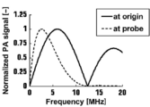
例えば、プローブ11の感度の中心周波数が6.5MHz(メガヘルツ)で、主要な観察対象の深さが4cm(センチメートル)の場合を考える。従来、被検体M内で発生する光音響波の中心周波数が6.5MHz(メガヘルツ)となるような励起光発生条件(レーザ光Lのパルス幅tLP=77ns(ナノ秒))を設定するのが一般的であったが、発生した光音響波は被検体M中で減衰する(特に高周波成分ほど多く減衰する)ため、光音響波のスペクトルを示すグラフである図2に示すように、プローブ11直前での光音響波の中心周波数は6.5MHz(メガヘルツ)からより低い中心周波数に変化してしまう。
For example, consider the case where the center frequency of the sensitivity of the probe 11 is 6.5 MHz (megahertz) and the depth of the main observation target is 4 cm (centimeter). Conventionally, an excitation light generation condition (pulse width t LP = 77 ns (nanoseconds) of the laser light L) is set such that the center frequency of the photoacoustic wave generated in the subject M is 6.5 MHz (megahertz). However, since the generated photoacoustic wave is attenuated in the subject M (in particular, it attenuates as the high frequency component increases), as shown in FIG. 2, which is a graph showing the spectrum of the photoacoustic wave, The center frequency of the photoacoustic wave immediately before 11 changes from 6.5 MHz (megahertz) to a lower center frequency.
一般にプローブ11の受信周波数帯域は、中心周波数に対して70%~100%の幅を持つ帯域であるため、中心周波数6.5MHz(メガヘルツ)のプローブ11で受信可能な音響波の周波数は3.2~9.8MHz(メガヘルツ)程度と考えられる。そのため、本実施形態においては、被検体M中での減衰を考慮して、プローブ11直前での光音響波の中心周波数が、中心周波数6.5MHz(メガヘルツ)のプローブ11で受信可能な周波数である3.2~9.8MHz(メガヘルツ)の成分の信号を多く含むように励起光発生条件を調整する。
Generally, since the reception frequency band of the probe 11 is a band having a width of 70% to 100% with respect to the center frequency, the frequency of acoustic waves that can be received by the probe 11 with a center frequency of 6.5 MHz (megahertz) is 3.. It is considered to be about 2 to 9.8 MHz (megahertz). Therefore, in the present embodiment, in consideration of attenuation in the subject M, the center frequency of the photoacoustic wave immediately before the probe 11 is a frequency that can be received by the probe 11 having a center frequency of 6.5 MHz (megahertz). The excitation light generation conditions are adjusted so as to include a large number of signals of a component of 3.2 to 9.8 MHz (megahertz).
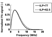
例えば、光音響波のスペクトルを示すグラフである図3に示すように、レーザ光Lのパルス幅tLP=62.5ns(ナノ秒)に設定すると、レーザ光Lのパルス幅tLP=77ns(ナノ秒)の場合と比較して、中心周波数6.5MHz(メガヘルツ)のプローブ11で受信可能な音響波の周波数は3.2~9.8MHz(メガヘルツ)の成分の信号を多く含むことができる。これにより、プローブ11における光音響波の受信効率を高めることができる。
For example, as shown in FIG. 3 which is a graph showing the spectrum of the photoacoustic wave, when the pulse width t LP of the laser light L is set to 62.5 ns (nanoseconds), the pulse width t LP of the laser light L is 77 ns ( Compared to the case of nanoseconds, the frequency of acoustic waves that can be received by the probe 11 with a center frequency of 6.5 MHz (megahertz) can include many signals of components of 3.2 to 9.8 MHz (megahertz) . Thereby, the receiving efficiency of the photoacoustic wave in the probe 11 can be raised.
このように、被検体M内における光音響波の減衰特性を考慮せずに、プローブ11の感度の中心周波数と被検体M内で発生する光音響波の中心周波数とが近くなるように励起光発生条件を設定したときのレーザ光Lのパルス幅よりも、励起光発生条件におけるレーザ光Lのパルス幅を短くすることで、プローブ11で受信可能な周波数帯域の成分の信号をより多く発生させることもできる。ここで、レーザ光Lのパルス幅をどの程度短くするかについては、被検体M内における光音響波の減衰特性に基づいて調整すればよく、具体的には、被検体M内における光音響波の減衰が大きい程(上記例では観察対象の深さが深くなる程)、レーザ光Lのパルス幅をより短くすればよい。
Thus, without considering the attenuation characteristic of the photoacoustic wave in the subject M, the excitation light is such that the center frequency of the sensitivity of the probe 11 and the center frequency of the photoacoustic wave generated in the subject M become close. By making the pulse width of the laser light L under the excitation light generation condition shorter than the pulse width of the laser light L when the generation condition is set, the signal of the component of the frequency band receivable by the probe 11 is generated more It can also be done. Here, how much the pulse width of the laser light L should be shortened may be adjusted based on the attenuation characteristics of the photoacoustic wave in the subject M, and more specifically, the photoacoustic wave in the subject M The pulse width of the laser beam L may be made shorter as the attenuation of the laser beam L increases (the depth of the observation target in the above example increases).
なお、プローブ11で受信可能な周波数帯域の成分の信号が多くなるような励起光発生条件のパターンについて、超音波ユニット12内部にあらかじめテーブルとしてプローブ11の種類毎に複数(例えば主要な観察対象が浅い場所に位置する場合用、中間の場所に位置する場合用、深い場所に位置する場合用など)記憶されていて、ユーザがそれらを選択できるようにしておくことが望ましい。
As for the pattern of the excitation light generation condition in which the signal of the component of the frequency band receivable by the probe 11 increases, a plurality (for example, main observation targets) for each type of the probe 11 as a table in the ultrasonic unit 12 in advance. It is desirable to be stored for shallow location, intermediate location, deep location, etc.) so that the user can select them.
このとき、光音響波の検波条件もそれぞれのモードに応じて最適化されていることが望ましい。また、光音響画像、または光音響画像と合成する超音波画像の画像深さ(画像における最大深さ)や焦点深さ(観察対象の深さ)に応じて、励起光発生条件が自動で切り替わるようにしてもよい。さらに、被検体Mの組織の種類に応じて励起光発生条件が自動で切り替わるようにしてもよい。
At this time, it is desirable that the detection conditions of the photoacoustic wave be optimized in accordance with each mode. In addition, the excitation light generation condition is automatically switched according to the photoacoustic image or the image depth (maximum depth in the image) or the focal depth (depth of the observation object) of the ultrasonic image to be synthesized with the photoacoustic image. You may do so. Furthermore, the excitation light generation condition may be automatically switched according to the type of tissue of the subject M.
また、レーザ光Lのパルス数は単発に限らず、2以上の複数としてもよい。
Further, the number of pulses of the laser light L is not limited to one, and may be two or more.
また、例えば、レーザ光Lのパルス数が増えた場合に、光音響画像中の物体位置が深い方向にずれるなど、励起光発生条件が変化することで、光音響画像中の物体位置が変化してしまう。そのため、光音響画像生成部24において、励起光発生条件に応じて、光音響画像中の物体位置を補正することが望ましい。
Also, for example, when the number of pulses of the laser light L increases, the object position in the photoacoustic image changes, such as the object position in the photoacoustic image shifts in a deep direction, and the excitation light generation condition changes. It will Therefore, it is desirable for the photoacoustic image generation unit 24 to correct the object position in the photoacoustic image according to the excitation light generation condition.
また、プローブ11直前での光音響波の中心周波数とプローブ11の感度における中心周波数を必ずしも一致させる必要はない。例えば、画質などの要請からプローブ11の感度における周波数帯域内の任意の箇所に光音響波の中心周波数を設定してもよい。
In addition, the center frequency of the photoacoustic wave immediately before the probe 11 and the center frequency in the sensitivity of the probe 11 do not necessarily have to coincide with each other. For example, the center frequency of the photoacoustic wave may be set at an arbitrary position in the frequency band in the sensitivity of the probe 11 from the requirement of the image quality and the like.
以上、本発明をその好適な実施形態に基づいて説明したが、本発明の光音響計測装置は、上記実施形態にのみ限定されるものではなく、上記実施形態の構成から種々の修正及び変更を施したものも、本発明の範囲に含まれる。
As mentioned above, although the present invention was explained based on the suitable embodiment, the photoacoustic measuring device of the present invention is not limited only to the above-mentioned embodiment, and various corrections and changes from the composition of the above-mentioned embodiment Those applied are also included in the scope of the present invention.
Claims (12)
- 光源から被検体に向けて出射された励起光を受けることにより前記被検体内から発生した光音響波を音響波検出手段により検出して得られた信号に基づいて光音響画像を生成する光音響画像生成部を備える光音響画像生成装置において、
前記光源に対して、前記音響波検出手段の受信周波数特性および前記被検体内における光音響波の減衰特性に基づいて、前記光源において発生させる励起光のパルス幅に基づいた励起光発生条件を調整する制御を行う制御部を備える光音響画像生成装置。 A photoacoustic image generating photoacoustic image based on a signal obtained by detecting a photoacoustic wave generated from the inside of the subject by an acoustic wave detection unit by receiving excitation light emitted toward the subject from a light source In a photoacoustic image generation apparatus including an image generation unit,
For the light source, based on the reception frequency characteristic of the acoustic wave detection means and the attenuation characteristic of the photoacoustic wave in the subject, adjust the excitation light generation condition based on the pulse width of the excitation light generated in the light source The photoacoustic image generating apparatus provided with the control part which performs control. - 前記制御部は、前記被検体内において発生する光音響波の周波数特性が異なる複数の前記励起光発生条件を記憶し、記憶している複数の前記励起光発生条件の中から選択された前記励起光発生条件に基づいて前記光源を制御する
請求項1記載の光音響画像生成装置。 The control unit stores a plurality of excitation light generation conditions having different frequency characteristics of photoacoustic waves generated in the subject, and the excitation selected from among the plurality of the excitation light generation conditions stored. The photoacoustic image generation apparatus according to claim 1, wherein the light source is controlled based on a light generation condition. - 前記制御部は、前記音響波検出手段の受信周波数特性が異なる種類毎に複数の前記励起光発生条件を記憶し、記憶している複数の前記励起光発生条件の中からユーザに選択された前記励起光発生条件に基づいて前記光源を制御する
請求項2記載の光音響画像生成装置。 The control unit stores a plurality of excitation light generation conditions for each type in which the reception frequency characteristics of the acoustic wave detection means are different, and the control unit is selected by the user from among the plurality of excitation light generation conditions stored. The photoacoustic image generation apparatus according to claim 2, wherein the light source is controlled based on excitation light generation conditions. - 前記制御部は、前記光音響画像の画像深さに基づいて、前記励起光発生条件を調整する
請求項1から3のいずれか1項記載の光音響画像生成装置。 The photoacoustic image generation apparatus according to any one of claims 1 to 3, wherein the control unit adjusts the excitation light generation condition based on an image depth of the photoacoustic image. - 前記制御部は、前記光音響画像の焦点深さに基づいて、前記励起光発生条件を調整する
請求項1から3のいずれか1項記載の光音響画像生成装置。 The photoacoustic image generation apparatus according to any one of claims 1 to 3, wherein the control unit adjusts the excitation light generation condition based on a focal depth of the photoacoustic image. - 前記光音響画像生成部は、前記励起光発生条件に基づいて、前記光音響画像に対して補正処理を施す
請求項1から5のいずれか1項記載の光音響画像生成装置。 The photoacoustic image generation apparatus according to any one of claims 1 to 5, wherein the photoacoustic image generation unit performs a correction process on the photoacoustic image based on the excitation light generation condition. - 光源から被検体に向けて出射された励起光を受けることにより前記被検体内から発生した光音響波を音響波検出手段により検出して得られた信号に基づいて光音響画像を生成する光音響画像生成部を備える光音響画像生成装置における画像取得方法であって、
前記光源に対して、前記音響波検出手段の受信周波数特性および前記被検体内における光音響波の減衰特性に基づいて、前記光源において発生させる励起光のパルス幅に基づいた励起光発生条件を調整する制御を行う画像取得方法。 A photoacoustic image generating photoacoustic image based on a signal obtained by detecting a photoacoustic wave generated from the inside of the subject by an acoustic wave detection unit by receiving excitation light emitted toward the subject from a light source An image acquisition method in a photoacoustic image generation apparatus comprising an image generation unit, comprising:
For the light source, based on the reception frequency characteristic of the acoustic wave detection means and the attenuation characteristic of the photoacoustic wave in the subject, adjust the excitation light generation condition based on the pulse width of the excitation light generated in the light source Image acquisition method to control the - 前記被検体内において発生する光音響波の周波数特性が異なる複数の前記励起光発生条件を記憶し、記憶している複数の前記励起光発生条件の中から選択された前記励起光発生条件に基づいて前記光源を制御する
請求項7記載の画像取得方法。 Based on the excitation light generation condition selected from among the plurality of excitation light generation conditions stored and stored a plurality of excitation light generation conditions having different frequency characteristics of the photoacoustic wave generated in the subject The image acquisition method according to claim 7, wherein the light source is controlled. - 前記音響波検出手段の受信周波数特性が異なる種類毎に複数の前記励起光発生条件を記憶し、記憶している複数の前記励起光発生条件の中からユーザに選択された前記励起光発生条件に基づいて前記光源を制御する
請求項8記載の画像取得方法。 A plurality of the excitation light generation conditions are stored for each type in which the reception frequency characteristics of the acoustic wave detection means are different, and the excitation light generation condition selected by the user from among the stored plurality of excitation light generation conditions is stored. The image acquisition method according to claim 8, wherein the light source is controlled based on the image. - 前記光音響画像の画像深さに基づいて、前記励起光発生条件を調整する
請求項7から9のいずれか1項記載の画像取得方法。 The image acquisition method according to any one of claims 7 to 9, wherein the excitation light generation condition is adjusted based on an image depth of the photoacoustic image. - 前記光音響画像の焦点深さに基づいて、前記励起光発生条件を調整する
請求項7から9のいずれか1項記載の画像取得方法。 The image acquisition method according to any one of claims 7 to 9, wherein the excitation light generation condition is adjusted based on the focal depth of the photoacoustic image. - 前記励起光発生条件に基づいて、前記光音響画像に対して補正処理を施す
請求項7から11のいずれか1項記載の画像取得方法。 The image acquisition method according to any one of claims 7 to 11, wherein the correction process is performed on the photoacoustic image based on the excitation light generation condition.
Applications Claiming Priority (2)
| Application Number | Priority Date | Filing Date | Title |
|---|---|---|---|
| JP2017164588 | 2017-08-29 | ||
| JP2017-164588 | 2017-08-29 |
Publications (1)
| Publication Number | Publication Date |
|---|---|
| WO2019044594A1 true WO2019044594A1 (en) | 2019-03-07 |
Family
ID=65525345
Family Applications (1)
| Application Number | Title | Priority Date | Filing Date |
|---|---|---|---|
| PCT/JP2018/030838 WO2019044594A1 (en) | 2017-08-29 | 2018-08-21 | Photoacoustic image generation device and image acquisition method |
Country Status (1)
| Country | Link |
|---|---|
| WO (1) | WO2019044594A1 (en) |
Cited By (1)
| Publication number | Priority date | Publication date | Assignee | Title |
|---|---|---|---|---|
| WO2021048951A1 (en) * | 2019-09-11 | 2021-03-18 | 日本電信電話株式会社 | Photoacoustic probe |
Citations (3)
| Publication number | Priority date | Publication date | Assignee | Title |
|---|---|---|---|---|
| JP2016047077A (en) * | 2014-08-27 | 2016-04-07 | プレキシオン株式会社 | Photoacoustic imaging apparatus |
| JP2016047232A (en) * | 2014-08-27 | 2016-04-07 | プレキシオン株式会社 | Photoacoustic imaging apparatus |
| JP2017035407A (en) * | 2015-08-14 | 2017-02-16 | セイコーエプソン株式会社 | Photoacoustic sensor and electronic apparatus |
-
2018
- 2018-08-21 WO PCT/JP2018/030838 patent/WO2019044594A1/en active Application Filing
Patent Citations (3)
| Publication number | Priority date | Publication date | Assignee | Title |
|---|---|---|---|---|
| JP2016047077A (en) * | 2014-08-27 | 2016-04-07 | プレキシオン株式会社 | Photoacoustic imaging apparatus |
| JP2016047232A (en) * | 2014-08-27 | 2016-04-07 | プレキシオン株式会社 | Photoacoustic imaging apparatus |
| JP2017035407A (en) * | 2015-08-14 | 2017-02-16 | セイコーエプソン株式会社 | Photoacoustic sensor and electronic apparatus |
Cited By (1)
| Publication number | Priority date | Publication date | Assignee | Title |
|---|---|---|---|---|
| WO2021048951A1 (en) * | 2019-09-11 | 2021-03-18 | 日本電信電話株式会社 | Photoacoustic probe |
Similar Documents
| Publication | Publication Date | Title |
|---|---|---|
| CN102596049B (en) | Photo-acoustic device | |
| JP5275830B2 (en) | Optical ultrasonic tomographic imaging apparatus and optical ultrasonic tomographic imaging method | |
| US10098547B2 (en) | Photoacoustic measurement device, photoacoustic measurement method, and probe contact determination method | |
| US9995717B2 (en) | Object information acquiring apparatus and object information acquiring method | |
| WO2012077356A1 (en) | Probe for photoacoustic inspection, and photoacoustic inspection device | |
| JP2010125260A (en) | Biological testing apparatus | |
| EP2706905B1 (en) | Subject information obtaining apparatus and subject information obtaining method | |
| JP2011120796A (en) | Photoacoustic apparatus and method for controlling the same | |
| JP6049215B2 (en) | Photoacoustic measurement apparatus, signal processing apparatus and signal processing method used therefor | |
| US11119199B2 (en) | Acoustic wave image generation apparatus and acoustic wave image generation method | |
| WO2011152747A1 (en) | Photoacoustic material analysis | |
| US11399719B2 (en) | Probe for photoacoustic measurement and photoacoustic measurement apparatus including same | |
| CN104856728A (en) | Photoacoustic device | |
| JP2015126900A (en) | Photoacoustic apparatus | |
| WO2019044594A1 (en) | Photoacoustic image generation device and image acquisition method | |
| US20200187784A1 (en) | Photoacoustic image generation apparatus and image acquisition method | |
| JP6482686B2 (en) | Photoacoustic image generation system, apparatus, and method | |
| JP2014184025A (en) | Photoacoustic measuring device, probe, acoustic matching member, photoacoustic measuring method and contact determination method of probe | |
| JP2016073887A (en) | Biological examination apparatus | |
| JP5868458B2 (en) | measuring device | |
| WO2018235781A1 (en) | Acoustic wave image generation device and optoacoustic image analysis method | |
| JP2014138883A (en) | Biological examination apparatus | |
| WO2019044212A1 (en) | Photoacoustic image generation device and image acquisition method | |
| JP2018111050A (en) | Photoacoustic apparatus | |
| JP2017192841A (en) | Biological examination apparatus |
Legal Events
| Date | Code | Title | Description |
|---|---|---|---|
| 121 | Ep: the epo has been informed by wipo that ep was designated in this application |
Ref document number: 18849548 Country of ref document: EP Kind code of ref document: A1 |
|
| NENP | Non-entry into the national phase |
Ref country code: DE |
|
| 122 | Ep: pct application non-entry in european phase |
Ref document number: 18849548 Country of ref document: EP Kind code of ref document: A1 |
|
| NENP | Non-entry into the national phase |
Ref country code: JP |