WO2019044207A1 - 低周波治療器、および治療システム - Google Patents
低周波治療器、および治療システム Download PDFInfo
- Publication number
- WO2019044207A1 WO2019044207A1 PCT/JP2018/026459 JP2018026459W WO2019044207A1 WO 2019044207 A1 WO2019044207 A1 WO 2019044207A1 JP 2018026459 W JP2018026459 W JP 2018026459W WO 2019044207 A1 WO2019044207 A1 WO 2019044207A1
- Authority
- WO
- WIPO (PCT)
- Prior art keywords
- low frequency
- frequency treatment
- treatment device
- threshold
- treatment
- Prior art date
- Legal status (The legal status is an assumption and is not a legal conclusion. Google has not performed a legal analysis and makes no representation as to the accuracy of the status listed.)
- Ceased
Links
Images









Classifications
-
- A—HUMAN NECESSITIES
- A61—MEDICAL OR VETERINARY SCIENCE; HYGIENE
- A61N—ELECTROTHERAPY; MAGNETOTHERAPY; RADIATION THERAPY; ULTRASOUND THERAPY
- A61N1/00—Electrotherapy; Circuits therefor
- A61N1/02—Details
- A61N1/08—Arrangements or circuits for monitoring, protecting, controlling or indicating
-
- A—HUMAN NECESSITIES
- A61—MEDICAL OR VETERINARY SCIENCE; HYGIENE
- A61N—ELECTROTHERAPY; MAGNETOTHERAPY; RADIATION THERAPY; ULTRASOUND THERAPY
- A61N1/00—Electrotherapy; Circuits therefor
- A61N1/18—Applying electric currents by contact electrodes
- A61N1/32—Applying electric currents by contact electrodes alternating or intermittent currents
- A61N1/36—Applying electric currents by contact electrodes alternating or intermittent currents for stimulation
- A61N1/36014—External stimulators, e.g. with patch electrodes
- A61N1/36021—External stimulators, e.g. with patch electrodes for treatment of pain
-
- A—HUMAN NECESSITIES
- A61—MEDICAL OR VETERINARY SCIENCE; HYGIENE
- A61N—ELECTROTHERAPY; MAGNETOTHERAPY; RADIATION THERAPY; ULTRASOUND THERAPY
- A61N1/00—Electrotherapy; Circuits therefor
- A61N1/40—Applying electric fields by inductive or capacitive coupling ; Applying radio-frequency signals
- A61N1/403—Applying electric fields by inductive or capacitive coupling ; Applying radio-frequency signals for thermotherapy, e.g. hyperthermia
-
- A—HUMAN NECESSITIES
- A61—MEDICAL OR VETERINARY SCIENCE; HYGIENE
- A61F—FILTERS IMPLANTABLE INTO BLOOD VESSELS; PROSTHESES; DEVICES PROVIDING PATENCY TO, OR PREVENTING COLLAPSING OF, TUBULAR STRUCTURES OF THE BODY, e.g. STENTS; ORTHOPAEDIC, NURSING OR CONTRACEPTIVE DEVICES; FOMENTATION; TREATMENT OR PROTECTION OF EYES OR EARS; BANDAGES, DRESSINGS OR ABSORBENT PADS; FIRST-AID KITS
- A61F7/00—Heating or cooling appliances for medical or therapeutic treatment of the human body
- A61F7/007—Heating or cooling appliances for medical or therapeutic treatment of the human body characterised by electric heating
- A61F2007/0071—Heating or cooling appliances for medical or therapeutic treatment of the human body characterised by electric heating using a resistor, e.g. near the spot to be heated
-
- A—HUMAN NECESSITIES
- A61—MEDICAL OR VETERINARY SCIENCE; HYGIENE
- A61F—FILTERS IMPLANTABLE INTO BLOOD VESSELS; PROSTHESES; DEVICES PROVIDING PATENCY TO, OR PREVENTING COLLAPSING OF, TUBULAR STRUCTURES OF THE BODY, e.g. STENTS; ORTHOPAEDIC, NURSING OR CONTRACEPTIVE DEVICES; FOMENTATION; TREATMENT OR PROTECTION OF EYES OR EARS; BANDAGES, DRESSINGS OR ABSORBENT PADS; FIRST-AID KITS
- A61F7/00—Heating or cooling appliances for medical or therapeutic treatment of the human body
- A61F2007/0093—Heating or cooling appliances for medical or therapeutic treatment of the human body programmed
-
- A—HUMAN NECESSITIES
- A61—MEDICAL OR VETERINARY SCIENCE; HYGIENE
- A61F—FILTERS IMPLANTABLE INTO BLOOD VESSELS; PROSTHESES; DEVICES PROVIDING PATENCY TO, OR PREVENTING COLLAPSING OF, TUBULAR STRUCTURES OF THE BODY, e.g. STENTS; ORTHOPAEDIC, NURSING OR CONTRACEPTIVE DEVICES; FOMENTATION; TREATMENT OR PROTECTION OF EYES OR EARS; BANDAGES, DRESSINGS OR ABSORBENT PADS; FIRST-AID KITS
- A61F7/00—Heating or cooling appliances for medical or therapeutic treatment of the human body
- A61F2007/0094—Heating or cooling appliances for medical or therapeutic treatment of the human body using a remote control
-
- A—HUMAN NECESSITIES
- A61—MEDICAL OR VETERINARY SCIENCE; HYGIENE
- A61F—FILTERS IMPLANTABLE INTO BLOOD VESSELS; PROSTHESES; DEVICES PROVIDING PATENCY TO, OR PREVENTING COLLAPSING OF, TUBULAR STRUCTURES OF THE BODY, e.g. STENTS; ORTHOPAEDIC, NURSING OR CONTRACEPTIVE DEVICES; FOMENTATION; TREATMENT OR PROTECTION OF EYES OR EARS; BANDAGES, DRESSINGS OR ABSORBENT PADS; FIRST-AID KITS
- A61F7/00—Heating or cooling appliances for medical or therapeutic treatment of the human body
- A61F2007/0095—Heating or cooling appliances for medical or therapeutic treatment of the human body with a temperature indicator
- A61F2007/0096—Heating or cooling appliances for medical or therapeutic treatment of the human body with a temperature indicator with a thermometer
-
- A—HUMAN NECESSITIES
- A61—MEDICAL OR VETERINARY SCIENCE; HYGIENE
- A61F—FILTERS IMPLANTABLE INTO BLOOD VESSELS; PROSTHESES; DEVICES PROVIDING PATENCY TO, OR PREVENTING COLLAPSING OF, TUBULAR STRUCTURES OF THE BODY, e.g. STENTS; ORTHOPAEDIC, NURSING OR CONTRACEPTIVE DEVICES; FOMENTATION; TREATMENT OR PROTECTION OF EYES OR EARS; BANDAGES, DRESSINGS OR ABSORBENT PADS; FIRST-AID KITS
- A61F7/00—Heating or cooling appliances for medical or therapeutic treatment of the human body
- A61F7/007—Heating or cooling appliances for medical or therapeutic treatment of the human body characterised by electric heating
-
- A—HUMAN NECESSITIES
- A61—MEDICAL OR VETERINARY SCIENCE; HYGIENE
- A61N—ELECTROTHERAPY; MAGNETOTHERAPY; RADIATION THERAPY; ULTRASOUND THERAPY
- A61N1/00—Electrotherapy; Circuits therefor
- A61N1/02—Details
- A61N1/025—Digital circuitry features of electrotherapy devices, e.g. memory, clocks, processors
-
- A—HUMAN NECESSITIES
- A61—MEDICAL OR VETERINARY SCIENCE; HYGIENE
- A61N—ELECTROTHERAPY; MAGNETOTHERAPY; RADIATION THERAPY; ULTRASOUND THERAPY
- A61N1/00—Electrotherapy; Circuits therefor
- A61N1/02—Details
- A61N1/04—Electrodes
- A61N1/0404—Electrodes for external use
- A61N1/0472—Structure-related aspects
- A61N1/0492—Patch electrodes
-
- A—HUMAN NECESSITIES
- A61—MEDICAL OR VETERINARY SCIENCE; HYGIENE
- A61N—ELECTROTHERAPY; MAGNETOTHERAPY; RADIATION THERAPY; ULTRASOUND THERAPY
- A61N1/00—Electrotherapy; Circuits therefor
- A61N1/18—Applying electric currents by contact electrodes
- A61N1/32—Applying electric currents by contact electrodes alternating or intermittent currents
- A61N1/36—Applying electric currents by contact electrodes alternating or intermittent currents for stimulation
- A61N1/36014—External stimulators, e.g. with patch electrodes
- A61N1/3603—Control systems
- A61N1/36034—Control systems specified by the stimulation parameters
Definitions
- the present disclosure relates to low frequency therapy devices and treatment systems.
- a low frequency treatment device configured to apply an electrical stimulation to a region of the user's body by outputting a low frequency pulse to the region of the user through the electrode pad.
- Patent Document 1 discloses a low frequency treatment device in which a user can set an output intensity.
- a low frequency treatment device is disclosed that improves the convenience of the user.
- a treatment system is disclosed that improves user convenience.
- the low frequency treatment device is a parameter that causes an increase in the pain of the user's body, and an acquisition unit that acquires a weather parameter related to weather, a treatment unit that performs low frequency treatment, a weather parameter, And a controller configured to adjust the intensity of the low frequency treatment based on a predetermined threshold value.
- the acquisition unit acquires barometric pressure or air temperature as a meteorological parameter at the position of the low frequency treatment device, and the adjustment unit determines that the air temperature or barometric pressure acquired by the acquisition unit is lower than the first threshold If so, adjust to strengthen the intensity of the low frequency treatment.
- the adjustment unit includes a generation unit that generates a therapeutic current, and executes a process of increasing the amplitude of the therapeutic current waveform as a process of enhancing the strength of the low frequency treatment.
- the treatment unit is capable of performing thermal treatment
- the adjustment unit enhances the strength of the thermal treatment when it is determined that the temperature or pressure acquired by the acquisition unit is lower than the first threshold. To adjust.
- a notification is given that the user refrains from going out when the temperature or pressure is lower than the first threshold. 1 further comprising a notification unit.
- the information processing apparatus further comprises position information receiving means for receiving the input of the position information, and the obtaining unit obtains and obtains the atmospheric pressure or the temperature as the weather parameter at the position indicated by the position information received by the position information receiving means.
- the system further includes a second notification unit that notifies that the user's body pain may increase if it is determined that the temperature or pressure acquired by the unit is lower than the first threshold.
- the acquisition unit acquires the atmospheric pressure or the temperature as the weather parameter at the position of the low frequency treatment device, the second threshold is larger than the first threshold, and the adjustment unit is the temperature acquired by the acquisition unit Alternatively, if it is determined that the barometric pressure is higher than the second threshold value, the intensity of the low frequency treatment is adjusted to be reduced.
- the treatment unit can perform the thermal treatment, and the adjusting unit weakens the intensity of the thermal treatment when it is determined that the temperature or pressure acquired by the acquiring unit is higher than the second threshold. To adjust.
- a certain phase based on the weather parameter and the threshold, accept the mode to be set from the user among the first mode to adjust the intensity of low frequency treatment and the second mode not to adjust intensity of low frequency treatment It further comprises a department.
- a treatment system is a treatment system including a low frequency treatment device for performing low frequency treatment and a notification device capable of communicating with the low frequency treatment device, wherein the barometric pressure or the temperature at the position of the low frequency treatment device. And the notification device refrains from going out at a time when the air temperature or the air pressure becomes lower than the threshold when it is determined that the air temperature or the air pressure acquired by the acquisition unit becomes lower than the threshold. To notify.
- FIG. 1 is a view showing a schematic configuration of a treatment system 1; It is a figure which shows an example of a table. It is a figure which shows the external appearance of the low frequency treatment device 200.
- FIG. FIG. 2 schematically shows an internal configuration of a low frequency treatment device 200. It is a figure which shows the parameter etc. of a treatment waveform.
- FIG. 2 is a diagram showing an example of a functional configuration of a processor 210. It is a figure which shows a 2nd notification part. It is a figure which shows the flowchart of a low frequency treatment device. It is a figure which shows an example of a table. It is a figure which shows the flowchart of a low frequency treatment device. It is a figure which shows an example of a table.
- FIG. 2 is a diagram showing a schematic configuration of a treatment system 2. It is a figure which shows an example of a table. It is a figure which shows the flowchart of a low frequency treatment device. It is a figure which shows a 3rd notification part. It is a figure which shows the flowchart of a low frequency treatment device.
- FIG. 2 is a diagram showing a schematic configuration of a treatment system 3. It is a figure which shows the external appearance of the low frequency treatment device 20.
- FIG. It is a figure which shows a 1st reception part. It is a figure which shows a 2nd reception part. It is a figure which shows a 3rd reception part. It is a figure which shows a 4th notification part. It is a figure which shows the flowchart of a low frequency treatment device.
- FIG. 1 is a view showing a schematic configuration of a treatment system 1 according to the first embodiment.
- the treatment system 1 includes a low frequency treatment device 200, a weather server 30 and a network 41.
- the network 41 includes various networks such as the Internet and a mobile terminal communication network in order to connect the low frequency treatment device 200 and the weather server 30 to each other.
- the weather server 30 comprises a table 32.
- the table 32 defines information in which position information and barometric pressure information indicating a barometric pressure at a position identified from the position information are associated.
- FIG. 2 shows an example of the table 32.
- the position information in the example of FIG. 2 includes the longitude X and the latitude Y, and the unit of the air pressure is “hectopascal (hPa)”.
- Z1 (hPa) is associated with the position information having the longitude X1 and the latitude Y1 as the atmospheric pressure. This indicates that the atmospheric pressure at the position where the longitude X1 and the latitude Y1 are is Z1 (hPa).
- the weather server 30 updates the barometric pressure information of each position defined in the table 32 to the latest barometric pressure information every predetermined time (for example, one hour).
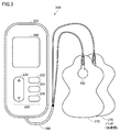
- FIG. 3 is a diagram illustrating an example of the appearance of the low frequency treatment device 200 according to the first embodiment.
- low frequency treatment device 200 according to the first embodiment electrically connects main body portion 205, a pair of pads 270 for attaching to a treatment site of a user, and main body portion 205 and pad 270. And a code 280 for the purpose.
- Pad 270 is an example of a “therapeutic unit” configured to contact a body part.
- the low frequency treatment device 200 is a wired type, and performs treatment such as loosening the shoulder of the user by supplying a low frequency pulse current.
- the frequency of the low frequency pulse current is 1 Hz to 1200 Hz.
- the low frequency treatment device 200 may be configured to use a pulse current of another frequency band.
- the pad 270 has a sheet-like shape and is attached to the body of the user. On one surface (surface not in contact with the body) of the pad 270, a plug corresponding to an electrode (not shown) formed on the other surface (surface in contact with the body) is provided.
- the electrode is formed of, for example, a conductive gel-like material or the like.
- the main body unit 205 is provided with an operation interface 230 composed of various buttons and a display 260.
- the operation interface 230 includes a power button 232 for switching on / off the power, a mode selection button 234 for selecting a treatment mode, a treatment start button 236, and the intensity of the electrical stimulation (hereinafter referred to as “electric stimulation And an adjustment button 238 for adjusting the intensity.
- the operation interface 230 is not limited to the above configuration, and may be any configuration that can realize various operations by the user.
- the operation interface 230 may be configured by, for example, other buttons, dials, switches, and the like.
- the display 260 displays the intensity of electrical stimulation, the remaining time of treatment, the treatment mode, the wearing condition of the pad 270, etc., and various messages.
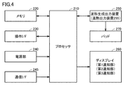
- FIG. 4 is a block diagram showing an example of a hardware configuration of the low frequency treatment device 200 according to the first embodiment.
- the low frequency therapy device 200 includes a processor 210, a memory 220, an operation interface 230, a power supply unit 240, a communication interface 245, a waveform generation and output device 250, and a display 260.
- the processor 210 is typically an arithmetic processing unit such as a central processing unit (CPU) or a multi processing unit (MPU).
- the processor 210 functions as a control unit that controls the operation of each unit of the low frequency therapy device 200 by reading and executing the program stored in the memory 220.
- the processor 210 implements each of the processes (steps) of the low frequency therapy device 200 described later by executing the program.
- the memory 220 is realized by a random access memory (RAM), a read-only memory (ROM), a flash memory, or the like.
- the memory 220 stores programs executed by the processor 210, data used by the processor 210, and the like.
- the operation interface 230 receives an operation input to the low frequency treatment device 200, and includes various buttons as described above. When the user operates the various buttons, a signal of the operation is input to the processor 210.
- the power supply unit 240 supplies power to each component of the low frequency treatment device 200.
- a power supply for example, an alkaline dry battery is used, and the power supply unit 240 stabilizes the battery voltage and generates a drive voltage to be supplied to each component.
- the processor 210 performs transmission and reception of various information with an external device, for example, the weather server 30, via the communication interface 245 and the network 41.
- the waveform generation output device 250 outputs a current (hereinafter also referred to as “treatment current”) flowing to the treatment site on the user's body through the pad 270.
- the waveform generation and output device 250 includes a booster circuit, a voltage adjustment circuit, an output circuit, a current detection circuit, and the like.
- the booster circuit boosts the power supply voltage to a predetermined voltage.
- the voltage adjustment circuit adjusts the voltage boosted by the booster circuit to a voltage corresponding to the electric stimulation intensity set by the user.
- adjustment of electrical stimulation can be set in a predetermined number of steps (for example, ten steps) by the adjustment button 238.
- the processor 210 receives the setting input of the electrical stimulation intensity via the adjustment button 238, and instructs the waveform generation and output device 250 (voltage adjustment circuit) to adjust to a voltage corresponding to the received electrical stimulation intensity.
- the output circuit generates a treatment waveform (pulse waveform) according to the treatment mode based on the voltage adjusted by the voltage adjustment circuit, and outputs the treatment waveform to (the electrode of) the pad 270 via the code 280.
- a control signal corresponding to the operation content is input from the processor 210 to the output circuit.
- Ru The output circuit outputs a treatment waveform according to the control signal.
- the low frequency treatment device 200 a plurality of treatment modes are prepared in advance.
- the treatment mode "Momi”, “Tataki”, “Push” mode and the like can be mentioned.
- the output circuit can generate an electrical stimulus corresponding to various modes such as "buzz”, “striking”, and “pushing” by changing a pulse waveform (including pulse width, pulse interval, output polarity) and the like.
- the electrical stimulation intensity can be adjusted by changing the amplitude of the pulse.
- known waveforms can be used.
- the treatment waveform may be not a pulse waveform but an AC waveform.
- the display 260 is configured by, for example, an LCD (Liquid Crystal Display), and displays various information according to an instruction from the processor 210.
- LCD Liquid Crystal Display
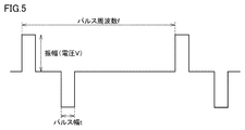
- FIG. 5 is a diagram illustrating an example of the therapeutic current output from the low frequency treatment device 200.
- the treatment waveform of the present embodiment will be described with reference to FIG.
- the parameters of the treatment waveform include the amplitude (voltage V), the pulse width t, and the pulse frequency f.
- the processor 210 can change the treatment for the user (changes the electrical stimulation intensity) by changing at least one of these three parameters.
- FIG. 6 is a diagram illustrating an example of a functional configuration of the processor 210.
- the functions of the processor 210 will be described using FIG.
- the acquisition unit 302 acquires weather parameters of a place where the low frequency treatment device 200 is located. Weather parameters result from an increase in user's body pain. Generally, for users with stiff shoulders and joint pain (hereinafter referred to as "body pain"), when the barometric pressure at the position where the user is present falls, the pain in the body becomes stronger (increases). Tend. In view of this tendency, in the present embodiment, the meteorological parameter is assumed to be atmospheric pressure. As described above, in the first embodiment, the acquisition unit 302 functions as an atmospheric pressure acquisition unit that acquires the atmospheric pressure.
- the acquisition unit 302 acquires position information indicating the position of the low frequency treatment device 200.
- the acquisition unit 302 acquires the position information using, for example, a GPS function (Global Positioning System).
- the acquisition unit 302 transmits the position information to the weather server 30 via the communication interface 245 and the network 41.
- the weather server 30 receives the position information
- the weather server 30 is the position information defined in the table 32, and the same position as the atmospheric pressure corresponding to the position information closest to the received position information or the received position information Extract the barometric pressure corresponding to the information.
- the weather server 30 transmits the extracted air pressure to the low frequency treatment device 200 as air pressure information.
- the acquisition unit 302 acquires the transmitted barometric pressure information via the network 41 and the communication interface 245.
- the acquisition unit 302 transmits pressure information to the determination unit 304.
- an atmospheric pressure threshold is stored in the memory 220.
- the pressure threshold is predetermined.
- the determination unit 304 determines whether the atmospheric pressure indicated by the atmospheric pressure information transmitted from the acquisition unit 302 is lower than the atmospheric pressure threshold stored in the memory 220. As described above, since the determination unit 304 determines the magnitude of the air pressure acquired by the acquisition unit 302, the determination unit 304 functions as an air pressure determination unit.
- the determination unit 304 outputs the determination result to the adjustment unit 306. If the adjustment unit 306 analyzes the judgment result and the air pressure acquired by the acquisition unit 302 is lower than the air pressure threshold, the adjustment unit 306 increases the strength of the low frequency treatment. , Adjust the intensity of the low frequency treatment.
- the adjustment unit 306 outputs an increase signal to the waveform generation and output device 250.
- the increase signal is a signal for increasing the intensity (eg, electrical stimulation intensity) of low frequency treatment by the pad 270.
- the waveform generation and output device 250 changes the treatment waveform (hereinafter referred to as “increased treatment waveform”) to increase the intensity of the low frequency treatment by the pad 270.
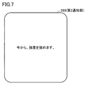
- FIG. 7 is a diagram showing an example of information to change to the augmentation treatment waveform.
- the characters “I will strengthen the strength from now” are notified as “information to change to the augmentation treatment waveform”.
- the process of displaying such characters is also referred to as "increase notification”.
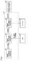
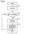
- FIG. 8 is a flowchart of the low frequency treatment device 200.
- the flowchart of the low frequency treatment device 200 will be described with reference to FIG.
- the flowchart of FIG. 8 and a flowchart to be described later are started when the low frequency treatment device 200 is powered on.
- step S102 the acquisition unit 302 acquires, from the weather server 30, the pressure at or near the location where the low frequency treatment device 200 is located.
- step S104 the determination unit 304 determines whether the air pressure acquired by the acquisition unit 302 is lower than the air pressure threshold. If it is determined that the atmospheric pressure acquired by the acquiring unit 302 is equal to or higher than the atmospheric pressure threshold (NO in step S104), the process ends. When it is determined that the atmospheric pressure acquired by the acquiring unit 302 is lower than the atmospheric pressure threshold (YES in step S104), the process proceeds to step S106.
- step S106 the adjustment unit 306 causes the display 260 to execute an increase notification (see FIG. 7).
- the processor 210 proceeds to step S108.
- step S108 the adjustment unit 306 changes the treatment waveform to the augmentation treatment waveform to strengthen the strength of the low frequency treatment.
- the second and subsequent processes in FIG. 8 are executed every predetermined time (for example, one minute). Further, if the process of step S108 is performed even once, the process of FIG. 8 is not performed. For example, when the process of step S108 is performed, an adjusted flag indicating that the adjustment of the low frequency treatment has been performed is stored in the predetermined area.
- the predetermined area is, for example, a RAM in the memory 220. If this adjusted flag is stored, the process of FIG. 8 is not performed.
- the adjusted flag is erased, for example, when the low frequency treatment device 200 is powered off.
- the low frequency treatment device 200 of the present embodiment increases the strength of the low frequency treatment when the air pressure at the location where the low frequency treatment device 200 is located becomes lower than the air pressure threshold.
- the user who is performing low frequency treatment by the low frequency treatment device 200 does not have to increase the strength of the low frequency treatment even if the barometric pressure becomes lower than the barometric pressure threshold, and the low frequency treatment device 200
- the strength of the low frequency treatment the convenience of the user can be enhanced.
- the low frequency treatment device 200 executes a process of increasing the amplitude of the waveform of the treatment current as a process of enhancing the strength of the low frequency treatment. The reason is that changing a parameter other than the amplitude may cause the user to feel uncomfortable. By increasing the amplitude value, the low frequency treatment device 200 can strengthen the strength of the low frequency treatment while making it difficult for the user to feel discomfort.
- an increase notification is performed before the low frequency treatment is strengthened.
- the increase notification can allow the user to recognize in advance that the strength of the low frequency treatment is intensified. Therefore, it is possible to prevent the strength of the low frequency treatment from increasing for the user.
- the low frequency treatment device 200 of the second embodiment can execute thermal treatment in addition to low frequency treatment.
- the user can select one of the low frequency treatment mode and the thermal treatment mode by operating the operation interface 230, for example.
- a heating member is embedded inside the pad of the second embodiment.
- the heating member is, for example, a coil that emits heat.
- the temperature is exemplified as the meteorological parameter resulting from the increase in the pain of the user's body.
- the weather server 30 includes the table 34 (see FIG. 1) in which the position information and the temperature information of the position specified from the position information are associated.
- FIG. 9 shows an example of the table 34.
- times is matched as temperature with the positional information used as longitude X1 and latitude Y1. This indicates that the temperature at the position where the longitude X1 and the latitude Y1 are is W1 degrees.
- the weather server 30 updates the temperature information defined in the table 34 to the latest temperature information every predetermined time (for example, one hour).
- the acquisition unit 302 acquires the temperature (temperature) of the place where the low frequency treatment device 200 is located. As described above, in the second embodiment, the acquisition unit 302 functions as a temperature acquisition unit that acquires the temperature. In the present embodiment, the acquisition unit 302 acquires position information indicating the position of the low frequency treatment device 200. The acquisition unit 302 acquires the position information using, for example, a GPS function (Global Positioning System). The acquisition unit 302 transmits the position information to the weather server 30 via the communication interface 245 and the network 41.
- GPS function Global Positioning System
- the weather server 30 When the weather server 30 receives the position information, the weather server 30 is the position information defined in the table 34, and the same position as the air temperature corresponding to the position information closest to the received position information, or the received position information Extract the temperature corresponding to the information.
- the weather server 30 transmits the extracted air temperature to the low frequency treatment device 200 as air temperature information.
- the acquisition unit 302 acquires the transmitted temperature information via the network 41 and the communication interface 245.
- the acquisition unit 302 transmits temperature information to the determination unit 304.
- a temperature threshold is stored in the memory 220. This temperature threshold is predetermined.
- the determination unit 304 determines whether the air temperature indicated by the air temperature information transmitted from the acquisition unit 302 is lower than the air temperature threshold stored in the memory 220. As described above, the determination unit 304 functions as a temperature determination unit because the determination unit 304 determines whether the temperature acquired by the acquisition unit 302 is large or small.
- the determination unit 304 outputs the determination result to the adjustment unit 306.
- the adjustment unit 306 analyzes the determination result and outputs an increase signal to the waveform generation and output device 250 when the temperature acquired by the acquisition unit 302 is lower than the air temperature threshold.
- the increase signal is a signal for increasing the strength of the thermal treatment by the pad 270.
- the thermal output device 255 raises the temperature of the pad 270 by increasing the temperature of the coil in the pad 270.
- a method of increasing the temperature of the coil for example, a method of increasing the temperature of the coil may be used by increasing the current supplied to the coil.
- the display 260 displays information to the effect that the temperature of the pad 270 is increased.
- the information indicating that the temperature of the pad 270 is to be increased characters such as “I will raise the temperature from now” are displayed.
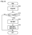
- FIG. 10 is a flowchart of the low frequency treatment device 200. The flowchart of the low frequency treatment device 200 will be described with reference to FIG.
- step S202 the acquisition unit 302 acquires the temperature of the place where the low frequency treatment device 200 is located from the weather server 30.
- step S204 the determination unit 304 determines whether the temperature acquired by the acquisition unit 302 is lower than the air temperature threshold.
- a process is complete finished when it is judged that the air temperature which the acquisition part 302 acquired is more than an air temperature threshold value (it is NO at step S204).
- the process proceeds to step S206.
- step S206 the adjustment unit 306 causes the display 260 to execute an increase notification (notice of information to increase the temperature of the pad 270).
- step S206 ends, the process of the processor 210 proceeds to step S208.
- step S208 the adjustment unit 306 enhances the strength of the thermal treatment, that is, raises the temperature of the pad 270.
- the processing of FIG. 10 after the second time is executed every predetermined time (for example, one minute). Further, if the process of step S208 is performed even once, the process of FIG. 10 is not performed. For example, when the process of step S208 is performed, an adjusted flag indicating that the adjustment of the thermal treatment has been performed is stored in the predetermined area.
- the predetermined area is, for example, a RAM in the memory 220. If this adjusted flag is stored, the process of FIG. 10 is not executed.
- the adjusted flag is erased, for example, when the low frequency treatment device 200 is powered off.
- the low frequency treatment device 200 of the second embodiment can increase the strength of the thermal treatment when the temperature of the place where the low frequency treatment device 200 is located becomes lower than the air temperature threshold. As a result, the user who is performing thermal treatment with the low frequency treatment device 200 does not have to increase the strength of the thermal treatment even if the air temperature becomes lower than the air temperature threshold, and the low frequency treatment device 200 is the thermal treatment. Can enhance the convenience of the user.
- the increase notification is executed before the strength of the thermal treatment is increased.
- the notification of the increase can allow the user to recognize in advance that the strength of the thermal treatment is intensified. Therefore, it is possible to prevent the user from unintentionally increasing the intensity of the thermal treatment.
- the third embodiment will be described.
- the display 260 is notified that the user will not go outside when the air pressure becomes lower than the air pressure threshold.
- the weather server 30 has a table 36 in which position information, a plurality of time zones in the position information, and an air pressure in the time zone are associated.
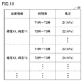
- FIG. 11 shows an example of the table 36.
- the position information in the example of FIG. 2 includes longitude X and latitude Y.
- the time zone is obtained by dividing a predetermined period in units of predetermined time (for example, one hour).
- the predetermined period may be, for example, any period, but is, for example, a period in which the user is predicted to go out.
- the period in which the user is expected to go out is, for example, a period from 6 am to 12 am
- Z1 (hPa) is associated in the time zone from T1 to T2 (time interval is one hour) in the position information having longitude X1 and latitude Y1, and T2 to T3.
- Z1 (hPa) is associated in the time zone up to time (time interval is one hour).
- Z3 (hPa) is associated in the time zone from T1 to T2 (time interval is one hour)
- T2 to T3 time
- Z4 (hPa) is associated with the interval.
- the barometric pressure is also defined for other times.
- the time zone and the barometric pressure are prescribed also about other position information.
- the table 36 of FIG. 11 predicts the barometric pressure in each time zone of one day.
- the weather server 30 constructs the table 36 of FIG. 11 by acquiring weather prediction data from a predetermined facility (for example, the Japan Meteorological Agency) at a predetermined time of day (for example, 1 o'clock in the middle of the night).
- a predetermined facility for example, the Japan Meteorological Agency
- a predetermined time of day for example, 1 o'clock in the middle of the night.
- FIG. 12 is a diagram showing a flowchart of the low frequency treatment device 200 of the third embodiment. The flowchart of the low frequency treatment device 200 will be described with reference to FIG.
- the low frequency treatment device 200 When the low frequency treatment device 200 is powered on, the low frequency treatment device 200 transmits position information.
- the weather server 30 receives the position information, it corresponds to the position information defined in the table 36, which is the position information closest to the received position information (or the same position information as the received position information). Time zone and barometric pressure are extracted.
- the weather server 30 transmits the time zone and the barometric pressure to the low frequency treatment device 200.
- the processor 210 obtains the transmitted time zone and the barometric pressure.
- the processor 210 determines whether or not there is an atmospheric pressure that is equal to or lower than the atmospheric pressure threshold in the acquired atmospheric pressure. Here, if it is determined that an atmospheric pressure which is equal to or lower than the atmospheric pressure threshold exists in the acquired atmospheric pressure, it means that a time zone which is equal to or lower than the atmospheric pressure threshold exists on the day when the process of FIG. 12 is performed.
- Step S304 processing of processor 210 progresses to Step S306. On the other hand, if it is determined NO in step S304, the processing of the processor 210 ends.
- step S306 the time of the start of the time zone corresponding to the barometric pressure which is equal to or lower than the barometric pressure threshold is extracted, and the time X from the current time to the extracted time (the time when the barometric pressure becomes the barometric pressure threshold) is calculated.
- the processor 210 calculates the time X, it causes the display 260 to notify the information that "they will not go out after X hours".
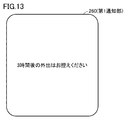
- the display 260 as the first notification unit, notifies that the user will not go out at a time when the air pressure becomes lower than the air pressure threshold when it is determined that the air pressure becomes lower (in the future) than the air pressure threshold. .
- FIG. 13 shows an example of notification on the display 260 when the calculated time is “3 hours”. The user can recognize that the atmospheric pressure reaches the atmospheric pressure threshold after 3 hours and that it is better to refrain from going out after 3 hours.
- the low frequency treatment device 200 prevents the pain of the user's body from intensifying while the user is out when the pressure reaches the pressure threshold by notifying as shown in FIG. 13 as much as possible. it can.
- the notification is not limited to that shown in FIG. 13, but may be a notification including a time zone.
- the notification may be "Please refrain from going out from 1 pm to 3 pm".
- the low frequency treatment device 200 acquires the time zone and the atmospheric pressure transmitted from the meteorological server 30 in step S302, and whether or not the atmospheric pressure obtained in step S304 is lower than the atmospheric pressure threshold.
- the weather server 30 may execute the determination of step S304. That is, the low frequency treatment device 200 transmits the atmospheric pressure threshold to the weather server 30 in addition to the position information.
- the weather server 30 receives the position information and the barometric pressure threshold, the weather server 30 determines whether or not there is a barometric pressure threshold corresponding to the position information, that is, the weather server 30 executes a determination process corresponding to step S304.
- the weather server 30 determines that there is an atmospheric pressure threshold value corresponding to the position information
- the time zone corresponding to the atmospheric pressure threshold value is transmitted. Thereafter, the low frequency treatment device 200 performs the process of step S306.
- the weather server 30 determines that the atmospheric pressure threshold value corresponding to the position information does not exist
- the weather server 30 transmits information to the effect that the weather server 30 does not exist to the low frequency therapy device 200.
- the low frequency treatment device 200 receives the information, the low frequency treatment device 200 does not execute the process of step S306. Even if it is a treatment system which employ
- the fourth embodiment will be described.
- the concept described in the third embodiment is replaced with "air pressure" to "air temperature". That is, in the fourth embodiment, when the low frequency treatment device 200 determines that the air temperature becomes lower than the air temperature threshold in the future, the display 260 is notified that the user refrains from going out when the air temperature becomes lower than the air temperature threshold. .
- the display 260 prevents the user from going out at a time when the air temperature becomes lower than the air temperature threshold when it is determined that the air temperature becomes lower (in the future) than the air temperature threshold. Notice.
- FIG. 13 shows an example of notification on the display 260 when the calculated time is “3 hours”. The user can recognize that the air temperature reaches the air temperature threshold three hours later and that it is better to refrain from going out three hours later.
- the low frequency treatment device 200 prevents the pain of the user's body from increasing while the user is out when the temperature reaches the temperature threshold by notifying as shown in FIG. 13. it can.
- the treatment facility is, for example, a facility that treats the user's body pain.
- FIG. 14 is a diagram showing a schematic configuration of a treatment system 2 according to the fifth embodiment. Comparing FIG. 14 with FIG. 1, FIG. 14 differs from FIG. 1 in that the facility server 40 is further provided.
- the facility server 40 includes a table 42.
- the table 42 defines position information and information in which a treatment facility specified from the position information is associated.
- FIG. 15 shows an example of the table 42.
- the position information in the example of FIG. 15 includes longitude and latitude.
- the position information, the treatment information indicating the treatment facility existing at the position indicated by the position information, and the treatment contents that can be performed by the treatment facility are associated.
- the CC shop of BB city in AA prefecture, and the CC shop can carry out low frequency treatment and thermal treatment as treatment contents It is shown.
- FIG. 16 is a diagram showing a flowchart of the low frequency treatment device 200 of the fifth embodiment.
- the flowchart of the low frequency treatment device 200 will be described with reference to FIG. Step S402 and step S404 are the same as step S102 and step S104 of FIG. If YES is determined in step S404, that is, if it is determined that the air pressure is lower than the air pressure threshold, the process of the processor 210 proceeds to step S406.
- the processor 210 transmits, to the facility server 40, position information of the low frequency treatment device 200 including the processor 210 and processing information indicating processing contents that can be executed by the low frequency treatment device 200.
- the facility server 40 is a treatment facility within a predetermined distance from the transmitted position information, and is further referred to as a treatment facility capable of treating a treatment that can not be performed by the low frequency treatment device 200 (hereinafter referred to as “notification target treatment facility”). ) To determine if it exists.
- the predetermined distance is a predetermined distance, and in a certain phase, for example, a distance a user with pain in the body can move without putting a burden on the body.
- a treatment facility capable of treating a treatment that the low frequency treatment device 200 can not execute means, for example, “the low frequency treatment device 200 can not be performed when the low frequency treatment device 200 can not perform a thermal treatment.
- the "treatment” is, for example, "thermal treatment”.
- the facility server 40 transmits, to the low frequency treatment device 200, facility information indicating the name, the location, and the like of the notification target treatment facility.
- the facility server 40 transmits, to the low frequency therapy device 200, information indicating that the notification target treatment facility does not exist.
- the low frequency treatment device 200 determines YES in step S406 by receiving the facility information. In addition, the low frequency treatment device 200 determines NO in step S406 by receiving information indicating that there is no notification target treatment facility. When the determination in step S406 is NO, the processing in FIG. 16 is ended. When it is judged as YES by step S406, it progresses to step S408.
- step S408 under the control of the processor 210, the display 260 notifies, as a third notification unit, the treatment facilities around the place where the low frequency treatment device 200 is located.
- the notification is performed based on the facility information received by the low frequency treatment device 200.
- FIG. 17 shows an example of the notification. In the example of FIG. 17, the characters “The heat treatment is possible at BB treatment center CC treatment shop AA. Now with 30% discount!” Are displayed on the display 260.
- the second and subsequent processes of FIG. 16 are executed every predetermined time (for example, one minute). Further, if the process of step S408 is performed even once, the process of FIG. 16 is not performed. For example, when the process of step S408 is executed, a notified flag indicating that the treatment facility has been notified is stored in the predetermined area.
- the predetermined area is, for example, a RAM in the memory 220. If this notified flag is stored, the process of FIG. 16 is not executed.
- the notified flag is cleared, for example, when the low frequency treatment device is powered off.
- the low-frequency treatment device 200 can notify the user of the treatment at the treatment facility by performing the notification as shown in FIG. Also, the user can recognize the treatment facilities around the location where the low frequency treatment device 200 owned by the user is located. Furthermore, the notification shown in FIG. 17 allows the user to recognize a treatment facility that can carry out treatment that the low frequency treatment device 200 possessed by the user can not execute. Further, as shown in FIG. 17, information in which the treatment fee is discounted is notified. Therefore, the user can recognize that treatment can be received at the discounted treatment fee.
- the display 260 may be notified of the notification target treatment facility, and the treatment content that can not be performed by the low frequency treatment device 200 and the treatment fee may not be notified.
- the low-frequency treatment device 200 possessed by the user itself is used in the treatment facility rather than the low-frequency treatment.
- Low frequency therapy may be desired by the user.
- the user is made to recognize the notification-targeted treatment facility by notifying the display 260 of the notification target treatment facility.
- the treatment at the notified treatment facility may be promoted to the user.
- the user can recognize that he can receive low frequency treatment at the treatment facility.
- steps S402 and S404 of FIG. 16 are used in steps S402 and S404 of FIG. 16 as a modification of the fifth embodiment
- the air temperature and the atmospheric temperature threshold may be used in steps S402 and S404. . That is, steps S402 and S404 may be substituted for steps S202 and S204 of FIG. Even in the case of a treatment system adopting such a configuration, the same effects as in the fifth embodiment can be obtained.
- the pressure threshold used is described as one.
- the atmospheric pressure threshold used is the first atmospheric pressure threshold and the second atmospheric pressure threshold, that is, the atmospheric pressure threshold used is two. Further, it is assumed that the second atmospheric pressure threshold> the first atmospheric pressure threshold.
- the atmospheric pressure threshold (refer to step S104 in FIG. 8) described in the first embodiment is referred to as “first atmospheric pressure threshold”, and further including the second atmospheric pressure threshold.
- first atmospheric pressure threshold the atmospheric pressure threshold
- second atmospheric pressure threshold the atmospheric pressure threshold
- the strength of the low frequency treatment is increased.
- the user who is performing low frequency treatment with the low frequency treatment device 200 needs to strengthen the strength of the low frequency treatment even if the barometric pressure becomes lower than the barometric pressure threshold. Since the low frequency treatment device 200 enhances the strength of the low frequency treatment, the convenience of the user can be enhanced.
- the strength of the low frequency treatment is decreased. Thereby, the power consumption of the low frequency treatment device can be reduced.
- FIG. 18 is a flowchart of the sixth embodiment.
- the determination unit 304 determines whether the atmospheric pressure acquired by the acquisition unit 302 is lower than the first atmospheric pressure threshold. If it is determined that the atmospheric pressure acquired by the acquiring unit 302 is lower than the first atmospheric pressure threshold (YES in step S104), the process of the processor 210 proceeds to step S106. On the other hand, when it is determined that the atmospheric pressure acquired by the acquisition unit 302 is not lower than the first atmospheric pressure threshold (NO in step S104), the process of the processor 210 proceeds to step S502.
- step S502 the determination unit 304 determines whether the atmospheric pressure acquired by the acquisition unit 302 is higher than a second atmospheric pressure threshold. If it is determined that the atmospheric pressure acquired by the acquiring unit 302 is higher than the second atmospheric pressure threshold (YES in step S502), the process proceeds to step S504. If NO in step S502, the process ends.
- step S504 the adjustment unit 306 causes the display 260 to execute a decrease notification (not particularly shown).
- the decrease notification is a notification to weaken the intensity of the low frequency treatment.
- the decrease notification is, for example, a notification such as "We will weaken the strength from now.”
- step S506 the adjustment unit 306 executes processing to weaken the intensity of the low frequency treatment.
- the process is, for example, a process of transmitting a decrease signal to the waveform generation and output device 250.
- the reduction signal is a signal for reducing the intensity (e.g., electrical stimulation intensity) of the low frequency treatment by the pad 270.
- the waveform generation and output device 250 receives at least one of the three parameters (amplitude (voltage V), pulse width t, and pulse frequency f) by receiving the decrease signal. Reduce the intensity of stimulation.
- the second and subsequent processes of FIG. 18 are executed every predetermined time (for example, one minute).
- the low frequency treatment device of the sixth embodiment adjusts the intensity of the low frequency treatment based on the weather parameter (pressure) and a predetermined threshold value. For example, when it is determined that the barometric pressure acquired by the barometric pressure acquiring unit is higher than the second barometric pressure threshold by executing steps S502 to S506, the low frequency therapeutic device of the sixth embodiment performs the low frequency treatment. Reduce the intensity of treatment. Thereby, the power consumption of the low frequency treatment device can be reduced. Furthermore, since the processes in steps S104 to S108 are performed, the effects described in the first embodiment are also achieved.
- a decrease notification is performed before reducing the intensity of the low frequency treatment.
- the reduction notification can allow the user to recognize in advance that the intensity of the low frequency treatment is weakened. Therefore, it is possible to prevent the intensity of the low frequency treatment from being weakened for the user.
- steps S104 to S108 may not be performed in FIG. That is, after the process of step S102, the process proceeds to step S502. According to such a configuration, the processing load can be alleviated in that the processing of steps S104 to S108 is not performed.
- the atmospheric pressure is used as the meteorological parameter.
- the air temperature is used as the weather parameter.
- the first atmospheric pressure threshold in FIG. 18 is substituted for the first air temperature threshold
- the second atmospheric pressure threshold is substituted for the second air temperature threshold.
- the treatment for which the intensity is adjusted is described as “low frequency treatment”.
- treatment of a subject whose intensity is to be adjusted may be "thermal treatment”.
- FIG. 19 is a diagram showing a schematic configuration of a treatment system 3 of the seventh embodiment.
- the treatment system 3 includes a terminal device 10 used by a user, a low frequency treatment device 20, a weather server 30, and networks 41 and 43.
- the barometric pressure and the temperature are collectively referred to as a weather parameter.
- the atmospheric pressure threshold and the air temperature threshold are collectively referred to as a threshold. “Weather parameter is lower than the threshold” includes the concept “air pressure is lower than the air pressure threshold” and the concept “air temperature is lower than the air temperature threshold”.
- the terminal device 10 is an example of the “information processing device”.
- the terminal device 10 is, for example, a smartphone provided with a touch panel.
- the terminal device 10 may be another type of terminal device such as a foldable mobile phone, a tablet terminal device, a personal computer (PC), a personal data assistance (PDA) or the like.
- the terminal device 10 also has a touch panel 158 capable of displaying various information and receiving input from the user.
- the touch panel 158 has the function of the display 260 described in FIG. 3 and the function of the operation interface 230.
- the network 43 employs a short distance wireless communication method, and typically, BLE (Bluetooth (registered trademark) low energy) is employed.
- BLE Bluetooth (registered trademark) low energy
- the network 43 is not limited to this, and a wired communication method may be adopted, or another wireless communication method such as a wireless LAN (local area network) may be adopted.
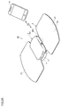
- FIG. 20 is a diagram illustrating the appearance of the low frequency treatment device 20 according to the first embodiment in association with the terminal device 10.
- the low frequency treatment device 20 includes a pad 2, a holder 7, and a main body 4.
- the low frequency treatment device 20 is a so-called cordless type and is controlled according to control information received from the terminal device 10.
- the pad 2 is an example of a “therapeutic unit” configured to be in contact with a part of the body.
- the pad 2 has a sheet-like shape, and is attached so as to contact a site of the user's body, more specifically, a site to be treated.
- a conductive layer 2 a is provided on the surface (lower surface) facing the body among the outer surfaces of the pads 2.
- the pad 2 is attached on the user's skin using a conductive gel or the like, and the user is supplied with a pulse current of a frequency according to the treatment program through the conductive layer 2a.
- the pad 2 has an attachment portion (not shown) and a treatment portion 2Y.
- the mounting portion is held by the holder 7.
- the holder 7 is positioned and arranged at the mounting portion.
- the treatment portion 2Y is provided on the left and right sides of the attachment portion, and the conductive layer 2a is exposed on the surface of the treatment portion 2Y facing the body.
- the conductive layer 2 a is also exposed on the surface facing the main body 4, and the exposed portion constitutes an electrode.
- the main body 4 includes a case 4a having a substantially rectangular parallelepiped shape as an exterior body.
- An engaging portion 5 is formed between the case 4 a and the holder 7, and the main body 4 (the case 4 a) is detachably attached to the holder 7 by the engaging portion 5.
- the main body 4 is provided with a switch 48S operated by the user to control the low frequency treatment device 20. Further, the main body 4 supplies a low frequency pulse current to the conductive layer 2 a of the pad 2 in a state of being attached to the holder 7.
- the main body 4 incorporates a substrate and an electric circuit and the like mounted on the substrate.
- the terminal device 10 determines whether or not the weather parameter is lower than a threshold, and an acquisition unit that acquires the weather parameter of the place where the low frequency therapy device 200 (or the terminal device 10) is located.
- a determination unit may be provided. In such a treatment system 3, at least one of the aforementioned technical ideas may be applied.
- At least one piece of information described in FIG. 7, FIG. 13, and FIG. 17 may be notified to the touch panel 158 of the terminal device 10. For example, when it is determined that the weather parameter is lower than the threshold, the touch panel 158 of the terminal device 10 notifies that the user will not go out when the weather parameter becomes lower than the threshold (the information illustrated in FIG. 13). You may
- a cordless type low frequency treatment device can also be adopted.
- the above-described acquisition unit, adjustment unit, and notification unit are not necessarily included in the above-described devices.
- Other devices may be provided as long as the embodiment described above can be implemented.
- the acquisition unit may not be included in the low frequency treatment device but may be included in the terminal device.
- the user may select the first mode and the second mode.
- the first mode is a mode in which the intensity of the low frequency treatment is adjusted based on the weather parameter and the threshold. That is, the first mode is a mode in which the strength of the low frequency treatment is enhanced when it is determined that the atmospheric pressure as the weather parameter is smaller than the first atmospheric pressure threshold.
- the second mode is a mode in which the intensity of the low frequency treatment is not adjusted regardless of the weather parameter and the threshold (regardless of the magnitude of the weather parameter and the threshold). That is, the second mode is a mode in which the intensity of the low frequency treatment is not changed (maintained) even when it is determined that the atmospheric pressure as the weather parameter is smaller than the first atmospheric pressure threshold.
- FIG. 21 is an example of a selection screen for accepting the selection of the mode.
- the selection screen is displayed on the display 260.
- the first mode and the second mode are displayed. The user can decide on any of these modes by moving the cursor.
- the first mode when it is determined that the atmospheric pressure as the weather parameter is smaller than the first atmospheric pressure threshold, it is displayed that the mode is to strengthen the strength of the low frequency treatment. .
- the second mode even in the case where it is determined that the atmospheric pressure as the meteorological parameter is smaller than the first atmospheric pressure threshold, the matter which is the mode not changing (maintaining) the intensity of low frequency treatment It is illustrated.
- the user who desires to intensify the low frequency treatment may automatically select the first mode. If it is determined that the weather parameter is lower than the threshold value, a user who does not want to strengthen the low frequency treatment automatically may select the second mode.
- the user's convenience can be further enhanced by the user being able to select the mode.
- the first mode is a mode in which the intensity of the low frequency treatment is enhanced when it is determined that the atmospheric pressure as the meteorological parameter is smaller than the first atmospheric pressure threshold, and the atmospheric pressure is the second If it is determined that the pressure is greater than the barometric pressure threshold, the mode may be one that weakens the intensity of the low frequency treatment.
- the second mode is a mode in which the intensity of the low frequency treatment is not changed (maintained) even when the atmospheric pressure as the weather parameter is determined to be smaller than the first atmospheric pressure threshold, and the atmospheric pressure is the second Even if it is determined that the pressure is greater than the barometric pressure threshold, the mode of maintaining (changing) the intensity of the low frequency treatment may be used.
- the first mode is a mode in which the intensity of the low frequency treatment is maintained even when the atmospheric pressure as the weather parameter is determined to be smaller than the first atmospheric pressure threshold, while the atmospheric pressure is higher than the second atmospheric pressure threshold. If it is determined to be large, the mode may be set to reduce the intensity of low frequency treatment. That is, the first mode may be a mode in which the intensity of the low frequency treatment is adjusted based on the weather parameter and the threshold.
- the pressure threshold and the temperature threshold are both predetermined.
- the user may set at least one of the barometric pressure threshold and the temperature threshold. This setting can be accepted as a second accepting unit from operation interface 230 or touch panel 158, for example.
- a user who recognizes a barometric pressure at which his / her body pain increases may be set as the barometric pressure threshold.
- a user who recognizes the temperature at which his or her body pain increases may set the temperature as a temperature threshold.
- FIG. 22 is an example of an input screen for inputting a threshold.
- the input screen is displayed on the display 260.
- the user can set at least one of the barometric pressure threshold and the temperature threshold, so that at least one of the low frequency treatment intensity and the thermal treatment intensity at a timing appropriate for the user. Can be strengthened. Thus, the convenience of the user can be further enhanced.
- the user may set at least one of the first atmospheric pressure threshold, the second atmospheric pressure threshold, the first air temperature threshold, and the second air temperature threshold.
- FIG. 23 is an example of a selection screen for accepting selection of a target of “strengthening”.
- the selection screen is displayed on the display 260. Further, in the example of FIG. 23, it is possible to input the degree of strengthening (a value to be multiplied by the selected parameter (gain value)) for the selected parameter.
- At least one of the three parameters (amplitude, pulse width, and pulse frequency) described in FIG. 5 may be selectable as the parameter to enhance the change to the treatment waveform.
- a user who does not want to feel discomfort when strengthening the strength of low frequency treatment may select the amplitude as a parameter to strengthen.
- a user who wants to feel different from the feeling of low frequency treatment before the increase in intensity of low frequency treatment selects at least one of pulse width and pulse frequency as an enhancement parameter. do it.
- This setting can be received, for example, from the operation interface 230 or the touch panel 158 as a third receiving unit.
- the value (gain value) to be multiplied by the selected parameter may be settable by the user.
- the user may set the gain value, and the low frequency treatment device 200 may increase the intensity of at least one of the low frequency treatment and the thermal treatment based on the set gain value.
- This setting can be received from, for example, operation interface 230 or touch panel 158.
- the user may set either one of the “strengthening target” and the “level of strengthening”. Also, as a modification, the user may set at least one of the “target of weakening strength” and the “degree of weakening”. That is, the input of the low frequency treatment intensity adjusted by the adjustment unit may be received.
- a specific member may be used for the treatment section of the low frequency treatment device.
- this specific member it is possible to generate heat (perform thermal treatment) or absorb heat (perform cooling treatment) by changing the polarity of the current or changing the magnitude of the current.
- the specific member is typically a Peltier element.
- thermal treatment and cooling treatment can be selectively performed by changing the polarity of the current or changing the magnitude of the current. Cooling treatment is generally considered to be effective against acute pain (eg, bruising etc.).
- the low frequency treatment device of this modification executes a process for cooling the specific member.
- the process for cooling the specific member is, for example, at least one process of the process of changing the polarity of the current and the process of changing the magnitude of the current.
- the low frequency treatment device of this modification when the temperature decreases, the specific member also cools, which may make it impossible to perform the treatment (for example, thermal treatment) intended by the user. Then, the low frequency treatment device of this modification performs processing for warming the specific member.
- the process for cooling the specific member is, for example, at least one process of the process of changing the polarity of the current and the process of changing the magnitude of the current.
- the low frequency treatment device 200 performs low frequency treatment
- thermal treatment can also be performed.
- it may be a thermal treatment device capable of performing thermal treatment without performing low frequency treatment.
- the concept described in the second embodiment may be applied to the thermal treatment device.
- the strength of the low frequency treatment device is strengthened when it is determined that the barometric pressure becomes smaller than the barometric pressure threshold. However, if it is determined that the air temperature has become smaller than the air temperature threshold, the intensity of the low frequency treatment may be increased. Further, in the second embodiment, it has been described that the strength of the thermal therapy device is strengthened when it is determined that the air temperature has become smaller than the air temperature threshold. However, if it is determined that the air pressure has become smaller than the air pressure threshold, the strength of the thermal treatment may be increased.
- the atmospheric pressure and the air temperature are exemplified as the meteorological parameters resulting from the increase in the pain of the user's body, but other parameters may be used.
- the low frequency therapy device 200 or the terminal device 10 has been described as acquiring weather parameters from the weather server.
- the low frequency treatment device 200 or the terminal device 10 may include a parameter detection unit (sensor), and the parameter detection unit may detect a weather parameter, and the acquisition unit may acquire the detected weather parameter.
- the treatment system can make the weather server 30 unnecessary.
- the notification in FIG. 7, FIG. 13, FIG. 17, etc. has been described as being displayed on the display 260 or the like.
- the notification may be voice notification.
- the notification may be a combination of display on the display 260 or the like and audio notification.
- FIG. 24 is a diagram for explaining the present modification. Further, it is assumed that the system configuration example of the present modification is as shown in FIG.
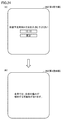
- the characters "Please input estimated arrival time and destination" are displayed on the display 260. Further, in the example of FIG. 24, the user can input the destination (the position (location) where the user is moving) and the estimated arrival time to the position of the moving destination as the fourth reception unit from the display 260. It has become. In the example of FIG. 24 (A), “13:15” is input as the estimated arrival time, and “Tokyo” is input as the destination (location (location) to move).
- a display screen as shown in FIG. 24B is displayed on the display 260 as a fourth notification unit.
- the characters “The pain in the body may increase in Tokyo” are displayed.
- the low frequency treatment device of this modification notifies that the user's body pain may increase at the input position and time.
- FIG. 25 is a diagram showing a flowchart of the low frequency treatment device of the present modification.
- the low frequency treatment device transmits position information (for example, longitude and latitude) indicating the input position and time information indicating the input time to the weather server.
- position information for example, longitude and latitude
- time information is time information indicating 13:15.
- the weather server transmits the barometric pressure corresponding to the position information and the time information transmitted from the low frequency treatment device to the low frequency treatment device.
- the weather server holds a table in which position information and time information are associated with atmospheric pressure.
- the weather server refers to the table to extract the air pressure corresponding to the position information and time information transmitted from the low frequency treatment device, and transmits the extracted air pressure to the low frequency treatment device.
- step S602 the low frequency treatment device acquires the transmitted pressure, that is, the pressure corresponding to the input position and the input time.
- step S604 the low frequency treatment device determines whether the acquired atmospheric pressure is lower than the atmospheric pressure threshold (corresponding to the first atmospheric pressure threshold described above).
- step S604 when it is determined as YES, in step S606, it is displayed that "a pain in the body may increase at the input position".
- the display is, for example, a display shown in FIG.
- the low frequency treatment device adopting this modification, it is notified that there is a possibility that the pain in the body may increase at the position and time inputted by the user. Therefore, at the destination of the user, the user can recognize whether or not the pain in the body may increase.
- step S104 if it is determined YES in step S104, that is, if it is determined that the barometric pressure is smaller than the first barometric pressure threshold, it is assumed that the strength of the low frequency treatment is strengthened. explained. In this way, if it is determined that the barometric pressure is greater than the first barometric pressure threshold while the intensity of the low frequency treatment is intensified, the intensity of the low frequency treatment is weakened (e.g. It may be possible to return.
- the pain of the user's body generally increases, but when the barometric pressure becomes larger than the first barometric pressure threshold, Generally, the user's body pain is reduced. Therefore, by reducing the intensity of the low frequency treatment, the power consumption of the low frequency treatment device can be reduced without making the user feel dissatisfied.
Landscapes
- Health & Medical Sciences (AREA)
- Life Sciences & Earth Sciences (AREA)
- Radiology & Medical Imaging (AREA)
- Engineering & Computer Science (AREA)
- Biomedical Technology (AREA)
- Nuclear Medicine, Radiotherapy & Molecular Imaging (AREA)
- Animal Behavior & Ethology (AREA)
- General Health & Medical Sciences (AREA)
- Public Health (AREA)
- Veterinary Medicine (AREA)
- Heart & Thoracic Surgery (AREA)
- Neurology (AREA)
- Pain & Pain Management (AREA)
- Biophysics (AREA)
- Electrotherapy Devices (AREA)
Abstract
ユーザの利便性を向上させる低周波治療器および治療システムを提供する。 取得部が、低周波治療器が位置する場所の気圧を取得し(ステップS102)、判断部が、気圧が閾値よりも低いか否かを判断し(ステップS104)と、治療部は、気圧が閾値よりも低いと判断された場合に、低周波治療の強度を強める(ステップS108)。
Description
本開示は、低周波治療器、および治療システムに関する。
低周波治療器として、電極パッドを通してユーザの身体部位に対して低周波パルスを出力することで電気刺激を当該部位に与えるように構成された低周波治療器が知られている。例えば、特許文献1では、ユーザが出力強度を設定できる低周波治療器が開示されている。
特許文献1の低周波治療器では、気象の変化により、ユーザの体の痛みが強まったとしても、ユーザ自身で出力強度を調整する必要があることから、ユーザの利便性が欠落しているものであった。
本開示は、上記のような実情に鑑みてなされたものであって、ある局面において、ユーザの利便性を向上させる低周波治療器が開示される。別の局面において、ユーザの利便性を向上させる治療システムが開示される。
この開示にかかる低周波治療器は、ユーザの体の痛みの増加の原因となるパラメータであって、気象に関する気象パラメータを取得する取得部と、低周波治療を行う治療部と、気象パラメータと、予め定められた閾値とに基づいて、低周波治療の強度を調整する調整部とを備える。
ある局面において、取得部は、低周波治療器の位置での気象パラメータとしての気圧または気温を取得し、調整部は、取得部により取得された気温または気圧が第1閾値よりも低いと判断した場合に、低周波治療の強度を強めるように調整する。
ある局面において、調整部は、治療用電流を生成する生成部を含み、低周波治療の強度を強める処理として、治療用電流の波形の振幅を増加させる処理を実行する。
ある局面において、治療部は、温熱治療を行うことが可能であり、調整部は、取得部により取得された気温または気圧が第1閾値よりも低いと判断した場合に、温熱治療の強度を強めるように調整する。
ある局面において、取得部により取得された気温または気圧が第1閾値よりも低くなると判断された場合に、該気温または該気圧が第1閾値よりも低くなる時期に外出を控える旨を通知する第1通知部をさらに備える。
ある局面において、位置情報の入力を受付ける位置情報受付手段をさらに備え、取得部は、位置情報受付手段が入力を受付けた位置情報が示す位置での気象パラメータとしての気圧または気温を取得し、取得部により取得された気温または気圧が第1閾値よりも低いと判断された場合に、ユーザの身体の痛みが増加する可能性があることを通知する第2通知部をさらに備える。
ある局面において、取得部は、低周波治療器の位置での気象パラメータとしての気圧または気温を取得し、第2閾値は、第1閾値よりも大きく、調整部は、取得部により取得された気温または気圧が第2閾値よりも高いと判断した場合に、低周波治療の強度を弱めるように調整する。
ある局面において、治療部は、温熱治療を行うことが可能であり、調整部は、取得部により取得された気温または気圧が第2閾値よりも高いと判断した場合に、温熱治療の強度を弱めるように調整する。
ある局面において、気象パラメータと、閾値とに基づいて、低周波治療の強度を調整する第1モードと、低周波治療の強度を調整しない第2モードとのうち、設定するモードをユーザから受付ける受付部をさらに備える。
この開示にかかる治療システムは、低周波治療を行う低周波治療器と、該低周波治療器と通信可能な通知装置とを含む治療システムであって、低周波治療器の位置での気圧または気温を取得する取得部を備え、通知装置は、取得部により取得された気温または気圧が閾値よりも低くなると判断された場合に、該気温または該気圧が閾値よりも低くなる時期に外出を控える旨を通知する。
この開示によれば、ユーザの利便性を向上させる低周波治療器、治療システムを提供することができる。
実施形態について、以下、図面を参照しながら説明する。同一の部品および相当部品には同一の参照番号を付し、重複する説明は繰り返さない場合がある。
[実施形態1]
<システム構成>
図1は、実施形態1に従う治療システム1の概略的な構成を示す図である。図1を参照して、治療システム1は、低周波治療器200、気象サーバ30およびネットワーク41を含む。ネットワーク41は、低周波治療器200と、気象サーバ30とを互いに接続するために、インターネット、移動体端末通信網などの各種ネットワークを含む。
<システム構成>
図1は、実施形態1に従う治療システム1の概略的な構成を示す図である。図1を参照して、治療システム1は、低周波治療器200、気象サーバ30およびネットワーク41を含む。ネットワーク41は、低周波治療器200と、気象サーバ30とを互いに接続するために、インターネット、移動体端末通信網などの各種ネットワークを含む。
気象サーバ30は、テーブル32を備える。テーブル32は、位置情報と、該位置情報から特定される位置の気圧を示す気圧情報とが対応付けられた情報が規定されている。図2は、該テーブル32の一例を示したものである。図2の例での位置情報は、経度Xと緯度Yとを含み、気圧の単位を「ヘクトパスカル(hPa)」とする。図2の例では、経度X1、緯度Y1となる位置情報には、気圧としてZ1(hPa)が対応付けられている。これは、経度X1、緯度Y1となる位置の気圧は、Z1(hPa)であることを示している。気象サーバ30は所定時間(たとえば、1時間)毎に、テーブル32で規定されている各位置の気圧情報を最新の気圧情報に更新する。
<低周波治療器200の構成>
図3は、実施形態1に従う低周波治療器200の外観の一例を表す図である。図3を参照して、実施形態1に従う低周波治療器200は、本体部205と、ユーザの治療部位に貼り付けるための一対のパッド270と、本体部205とパッド270とを電気的に接続するためのコード280とを含む。パッド270は、身体の部位に接触されるように構成される「治療部」の一実施例である。低周波治療器200は、有線タイプであり、低周波パルス電流を供給することで、ユーザの肩凝りをほぐす等の治療を行う。例えば、低周波パルス電流の周波数は、1Hz~1200Hzである。ただし、低周波治療器200は、これ以外の周波数帯のパルス電流を用いる構成であってもよい。
図3は、実施形態1に従う低周波治療器200の外観の一例を表す図である。図3を参照して、実施形態1に従う低周波治療器200は、本体部205と、ユーザの治療部位に貼り付けるための一対のパッド270と、本体部205とパッド270とを電気的に接続するためのコード280とを含む。パッド270は、身体の部位に接触されるように構成される「治療部」の一実施例である。低周波治療器200は、有線タイプであり、低周波パルス電流を供給することで、ユーザの肩凝りをほぐす等の治療を行う。例えば、低周波パルス電流の周波数は、1Hz~1200Hzである。ただし、低周波治療器200は、これ以外の周波数帯のパルス電流を用いる構成であってもよい。
パッド270は、シート状の形状を有し、ユーザの身体に取り付けられる。パッド270の一方の面(身体と接触しない面)には、他方の面(身体と接触する面)に形成されている電極(図示しない)に対応したプラグが設けられている。電極は、例えば、導電性のゲル状材料等により形成される。コード280のプラグ282とパッド270側のプラグとを接続し、コード280を本体部205のジャックに差し込むことにより、本体部205とパッド270とが接続される。なお、一方のパッド270に形成されている電極の極性がプラスの場合、他方のパッド270に形成されている電極の極性はマイナスとなる。
本体部205には、各種ボタンで構成される操作インターフェイス230と、ディスプレイ260とが設けられている。操作インターフェイス230は、電源のオン/オフを切り替えるための電源ボタン232と、治療モードの選択を行うためのモード選択ボタン234と、治療開始ボタン236と、電気刺激の強さ(以下、「電気刺激強度」とも称する。)の調整を行うための調整ボタン238とを含む。なお、操作インターフェイス230は、上記構成に限られず、ユーザによる各種操作を実現できる構成であればよい。操作インターフェイス230は、例えば、その他のボタン、ダイヤルやスイッチ等により構成されていてもよい。
ディスプレイ260には、電気刺激強度、治療の残り時間、治療モード、パッド270の装着状態等が表示されたり、各種メッセージが表示されたりする。
<ハードウェア構成>
図4は、実施形態1に従う低周波治療器200のハードウェア構成の一例を表すブロック図である。図4を参照して、低周波治療器200は、プロセッサ210と、メモリ220と、操作インターフェイス230と、電源部240と、通信インターフェイス245と、波形生成出力装置250と、ディスプレイ260とを含む。
図4は、実施形態1に従う低周波治療器200のハードウェア構成の一例を表すブロック図である。図4を参照して、低周波治療器200は、プロセッサ210と、メモリ220と、操作インターフェイス230と、電源部240と、通信インターフェイス245と、波形生成出力装置250と、ディスプレイ260とを含む。
プロセッサ210は、典型的には、CPU(Central Processing Unit)やMPU(Multi Processing Unit)といった演算処理部である。プロセッサ210は、メモリ220に記憶されたプログラムを読み出して実行することで、低周波治療器200の各部の動作を制御する制御部として機能する。プロセッサ210は、当該プログラムを実行することによって、後述する低周波治療器200の処理(ステップ)の各々を実現する。
メモリ220は、RAM(Random Access Memory)、ROM(Read-Only Memory)、フラッシュメモリなどによって実現される。メモリ220は、プロセッサ210によって実行されるプログラム、またはプロセッサ210によって用いられるデータなどを記憶する。
操作インターフェイス230は、低周波治療器200に対する操作入力を受け付け、上述したような各種ボタンより構成される。ユーザによって、各種ボタンが操作されると、当該操作による信号がプロセッサ210に入力される。
電源部240は、低周波治療器200の各構成要素に電力を供給する。電源としては、例えば、アルカリ乾電池が用いられ、電源部240は、電池電圧を安定化して各構成要素に供給する駆動電圧を生成する。
プロセッサ210は、通信インターフェイス245およびネットワーク41を経由して、外部装置、たとえば、気象サーバ30と種々の情報の送受信を実行する。波形生成出力装置250は、パッド270を介してユーザの身体の治療部位に流れる電流(以下、「治療電流」とも称する。)を出力する。波形生成出力装置250は、昇圧回路、電圧調整回路、出力回路、電流検出回路等を含む。
昇圧回路は、電源電圧を所定の電圧に昇圧する。電圧調整回路は、昇圧回路により昇圧された電圧を、ユーザにより設定された電気刺激強度に対応する電圧に調整する。具体的には、低周波治療器200では、調整ボタン238により所定数の段階(例えば、10段階)で、電気刺激の調整が設定可能である。プロセッサ210は、調整ボタン238を介して電気刺激強度の設定入力を受け付け、当該受け付けた電気刺激強度に対応する電圧に調整するように波形生成出力装置250(電圧調整回路)に指示する。
出力回路は、電圧調整回路により調整された電圧に基づいて、治療モードに応じた治療波形(パルス波形)を生成し、当該治療波形をコード280を介してパッド270(の電極)に出力する。具体的には、操作インターフェイス230を介して、ユーザにより、治療モードの切替、電気刺激強度の変更等の操作が行われると、その操作内容に応じた制御信号がプロセッサ210から出力回路に入力される。出力回路は、当該制御信号に従う治療波形を出力する。
低周波治療器200には、複数の治療モードが予め用意されている。例えば、治療モードとしては、「もみ」、「たたき」、「押し」モード等が挙げられる。
出力回路は、パルスの波形(パルス幅、パルス間隔、出力極性を含む)等を変化させることにより、「もみ」、「たたき」、「押し」といった様々なモードに対応する電気刺激を生成できる。また、パルスの振幅を変化させることにより、電気刺激強度を調整することができる。具体的な治療波形については、公知の波形を利用することができる。なお、治療波形は、パルス波形ではなく交流波形であってもよい。
ディスプレイ260は、例えば、LCD(liquid crystal display)で構成されており、プロセッサ210からの指示に従って各種情報を表示する。
<治療用電流>
図5は、低周波治療器200が出力する治療用電流の一例を表す図である。図5を参照して、本実施形態の治療波形を説明する。図5に示すように、治療波形のパラメータは、振幅(電圧V)と、パルス幅tと、パルス周波数fとを含む。プロセッサ210は、これら3つのパラメータのうち少なくとも1つのパラメータを変更することにより、ユーザに対する治療を変更することができる(電気刺激強度を変更することができる)。
図5は、低周波治療器200が出力する治療用電流の一例を表す図である。図5を参照して、本実施形態の治療波形を説明する。図5に示すように、治療波形のパラメータは、振幅(電圧V)と、パルス幅tと、パルス周波数fとを含む。プロセッサ210は、これら3つのパラメータのうち少なくとも1つのパラメータを変更することにより、ユーザに対する治療を変更することができる(電気刺激強度を変更することができる)。
<低周波治療器200の処理>
図6は、プロセッサ210の機能構成例を表す図である。図6を用いて、プロセッサ210の機能を説明する。取得部302は、低周波治療器200が位置する場所の気象パラメータを取得する。気象パラメータは、ユーザの体の痛みの増加に起因する。一般的に、肩こりや関節の痛みなど(以下、「体の痛み」という。)を持つユーザにとって、該ユーザが存在する位置での気圧が下ると、該体の痛みが強くなる(増加する)傾向がある。この傾向を鑑みて、本実施形態では、気象パラメータを気圧とする。このように、本実施形態1では、取得部302は、気圧を取得する気圧取得部として機能する。本実施形態では、取得部302は、低周波治療器200の位置を示す位置情報を取得する。該取得部302は、たとえば、GPS機能(Global Positioning System)を用いて、該位置情報を取得する。取得部302は、該位置情報を通信インターフェイス245およびネットワーク41を経由して、気象サーバ30に対して送信する。気象サーバ30は、該位置情報を受信すると、テーブル32で規定されている位置情報であって、該受信した位置情報と最も近い位置情報に対応する気圧、または該受信した位置情報と同一の位置情報に対応する気圧を抽出する。気象サーバ30は、該抽出した気圧を気圧情報として、低周波治療器200に対して送信する。取得部302は、ネットワーク41と通信インターフェイス245とを経由して、該送信された気圧情報を取得する。
図6は、プロセッサ210の機能構成例を表す図である。図6を用いて、プロセッサ210の機能を説明する。取得部302は、低周波治療器200が位置する場所の気象パラメータを取得する。気象パラメータは、ユーザの体の痛みの増加に起因する。一般的に、肩こりや関節の痛みなど(以下、「体の痛み」という。)を持つユーザにとって、該ユーザが存在する位置での気圧が下ると、該体の痛みが強くなる(増加する)傾向がある。この傾向を鑑みて、本実施形態では、気象パラメータを気圧とする。このように、本実施形態1では、取得部302は、気圧を取得する気圧取得部として機能する。本実施形態では、取得部302は、低周波治療器200の位置を示す位置情報を取得する。該取得部302は、たとえば、GPS機能(Global Positioning System)を用いて、該位置情報を取得する。取得部302は、該位置情報を通信インターフェイス245およびネットワーク41を経由して、気象サーバ30に対して送信する。気象サーバ30は、該位置情報を受信すると、テーブル32で規定されている位置情報であって、該受信した位置情報と最も近い位置情報に対応する気圧、または該受信した位置情報と同一の位置情報に対応する気圧を抽出する。気象サーバ30は、該抽出した気圧を気圧情報として、低周波治療器200に対して送信する。取得部302は、ネットワーク41と通信インターフェイス245とを経由して、該送信された気圧情報を取得する。
取得部302は、気圧情報を判断部304に対して送信する。また、メモリ220には、気圧閾値が記憶されている。本実施形態では、該気圧閾値は、予め定められている。判断部304は、取得部302から送信された気圧情報が示す気圧が、メモリ220に記憶されている気圧閾値よりも低いか否かを判断する。このように、判断部304は、取得部302が取得した気圧の大小を判断することから、気圧判断部として機能する。
判断部304は、調整部306に対して、判断結果を出力する。調整部306は、該判断結果を解析して、取得部302が取得した気圧が、気圧閾値よりも低い旨の結果である場合には、調整部306は、低周波治療の強度を強めるように、該低周波治療の強度を調整する。本実施形態では、調整部306は、波形生成出力装置250に対して増大信号を出力する。該増大信号は、パッド270による低周波治療の強度(たとえば、電気刺激強度)を増大させるための信号である。増大信号を出力することにより、波形生成出力装置250は、パッド270による低周波治療の強度を増大させるような治療波形(以下、「増大治療波形」という。)に変更する。
また、波形生成出力装置250が増大治療波形に変更するときには、ディスプレイ260に、増大治療波形に変更する旨の情報を表示する。図7は、増大治療波形に変更する旨の情報の一例を示した図である。図7の例では、第2通知部として「増大治療波形に変更する旨の情報」として、「今から、強度を強めます」という文字を通知する。以下では、このような文字を表示する処理を「増大通知」ともいう。
図8は、低周波治療器200のフローチャートを表す図である。図8を用いて、低周波治療器200のフローチャートを説明する。図8のフローチャート、および後述するフローチャートは、低周波治療器200の電源がONされたときに開始される。
まず、ステップS102において、取得部302は、低周波治療器200が位置する場所、または該場所の近傍の気圧を、気象サーバ30から取得する。
次に、ステップS104において、判断部304は、取得部302が取得した気圧が、気圧閾値よりも低いか否かを判断する。取得部302が取得した気圧が、気圧閾値以上であると判断した場合には(ステップS104でNO)、処理を終了する。また、取得部302が取得した気圧が、気圧閾値より低いと判断した場合には(ステップS104でYES)、ステップS106に進む。
ステップS106において、調整部306は、ディスプレイ260に対して増大通知(図7参照)を実行させる。プロセッサ210は、ステップS106の処理が終了すると、ステップS108に進む。
ステップS108において、調整部306が増大治療波形に変更することにより、低周波治療の強度を強める。
また、2回目以降の図8の処理は、所定時間(たとえば、1分)ごとに実行される。また、ステップS108の処理が1回でも実行された場合には、図8の処理は実行されなくなる。たとえば、ステップS108の処理が実行された場合には、低周波治療の調整が実行されたこと示す調整済フラグが所定領域に格納される。所定領域とは、たとえば、メモリ220内のRAMである。この調整済フラグが格納されている場合には、図8の処理は実行されない。この調整済フラグは、たとえば、低周波治療器200の電源がオフされた場合に、消去される。
次に、本実施形態の低周波治療器200が奏する効果について説明する。一般的に、体の痛みを持つユーザにとって、該ユーザが存在する位置での気圧が下ると、該体の痛みが強くなる傾向がある。この傾向を鑑みて、本実施形態の低周波治療器200は、該低周波治療器200が位置する場所の気圧が、気圧閾値よりも低くなったときに、低周波治療の強度を増大させることができる。これにより、低周波治療器200による低周波治療を行っているユーザは、気圧が気圧閾値よりも低くなったとしても、ユーザが低周波治療の強度を強める必要がなく、低周波治療器200が低周波治療の強度を強めることから、ユーザの利便性を高めることができる。
また、増大治療波形への変更については、図5で説明した3つのパラメータ(振幅、パルス幅、およびパルス周波数)のうち少なくとも1つを変更する。また、低周波治療器200が、低周波治療の強度を強める処理として、治療用電流の波形の振幅を増加させる処理を実行することが好ましい。理由は、振幅とは別のパラメータを変更すると、ユーザに違和感を感じさせる場合があるからである。低周波治療器200が、振幅の値を増加させることにより、ユーザに違和感を感じさせ難くしつつ、低周波治療の強度を強めることができる。
また、図8のステップS106で説明したように、低周波治療の強度を強める前に、増大通知が実行される。該増大通知により、低周波治療の強度が強まることをユーザに事前に認識させることができる。したがって、ユーザにとって不意に低周波治療の強度が強まってしまうことを防止できる。
[実施形態2]
ユーザによっては、痛みのある箇所に、低周波治療を施すよりも温熱治療を施した方が痛みが和らぐユーザがいる。そこで、実施形態2の低周波治療器200は、低周波治療の他に温熱治療も実行可能であるとする。ユーザは、たとえば、操作インターフェイス230への操作により、低周波治療モードと温熱治療モードとのうちのいずれか一方のモードを選択できる。また、実施形態2のパッドの内部には、温熱部材が埋め込まれている。温熱部材とは、たとえば、熱を発するコイルである。
ユーザによっては、痛みのある箇所に、低周波治療を施すよりも温熱治療を施した方が痛みが和らぐユーザがいる。そこで、実施形態2の低周波治療器200は、低周波治療の他に温熱治療も実行可能であるとする。ユーザは、たとえば、操作インターフェイス230への操作により、低周波治療モードと温熱治療モードとのうちのいずれか一方のモードを選択できる。また、実施形態2のパッドの内部には、温熱部材が埋め込まれている。温熱部材とは、たとえば、熱を発するコイルである。
また、実施形態2では、ユーザの体の痛みの増加に起因する気象パラメータとして、温度を例示する。実施形態2では、気象サーバ30は、位置情報と、該位置情報から特定される位置の気温情報とを対応付けられたテーブル34(図1参照)を備える。図9は、該テーブル34の一例を示したものである。図9の例では、経度X1、緯度Y1となる位置情報には、気温としてW1度が対応付けられている。これは、経度X1、緯度Y1となる位置の気温は、W1度であることを示している。気象サーバ30は所定時間(たとえば、1時間)毎に、テーブル34で規定されている気温情報を最新の気温情報に更新する。
図6を用いて、実施形態2の低周波治療器200のプロセッサ210の機能構成例を説明する。取得部302は、低周波治療器200が位置する場所の気温(温度)を取得する。このように、本実施形態2では、取得部302は、気温を取得する気温取得部として機能する。本実施形態では、取得部302は、低周波治療器200の位置を示す位置情報を取得する。該取得部302は、たとえば、GPS機能(Global Positioning System)を用いて、該位置情報を取得する。取得部302は、該位置情報を通信インターフェイス245およびネットワーク41とを経由して、気象サーバ30に対して送信する。気象サーバ30は、該位置情報を受信すると、テーブル34で規定されている位置情報であって、該受信した位置情報と最も近い位置情報に対応する気温、または該受信した位置情報と同一の位置情報に対応する気温を抽出する。気象サーバ30は、該抽出した気温を気温情報として低周波治療器200に対して送信する。取得部302は、ネットワーク41と通信インターフェイス245とを経由して、該送信された気温情報を取得する。
取得部302は、気温情報を判断部304に対して送信する。また、メモリ220には、気温閾値が記憶されている。この気温閾値は予め定められている。判断部304は、取得部302から送信された気温情報が示す気温が、メモリ220に記憶されている気温閾値よりも低いか否かを判断する。このように、判断部304は、取得部302が取得した気温の大小を判断することから、気温判断部として機能する。
判断部304は、調整部306に対して、判断結果を出力する。調整部306は、該判断結果を解析して、取得部302が取得した気温が、気温閾値よりも低い旨の結果である場合には、波形生成出力装置250に対して増大信号を出力する。該増大信号は、パッド270による温熱治療の強度を増大させるための信号である。増大信号を出力することにより、温熱出力装置255は、パッド270内のコイルの温度を増加させることにより、パッド270の温度を高める。コイルの温度を増加させる手法として、たとえば、コイルに流す電流を増加させることにより、コイルの温度を高める手法を用いればよい。
また、温熱出力装置255がパッド270の温度を増加させるときには、ディスプレイ260に、パッド270の温度を増加させる旨の情報を表示する。特に図示しないが、パッド270の温度を増加させる旨の情報として、「今から、温度を高めます」という文字が表示される。
図10は、低周波治療器200のフローチャートを表す図である。図10を用いて、低周波治療器200のフローチャートを説明する。
まず、ステップS202において、取得部302は、低周波治療器200が位置する場所の気温を、気象サーバ30から取得する。
次に、ステップS204において、判断部304は、取得部302が取得した気温が、気温閾値よりも低いか否かを判断する。取得部302が取得した気温が、気温閾値以上であると判断した場合には(ステップS204でNO)、処理を終了する。また、取得部302が取得した気温が、気温閾値より低いと判断した場合には(ステップS204でYES)、ステップS206に進む。
ステップS206において、調整部306は、ディスプレイ260に増大通知(パッド270の温度を増加させる旨の情報の通知)を実行させる。ステップS206の処理が終了すると、プロセッサ210の処理は、ステップS208に進む。
ステップS208において、調整部306は、温熱治療の強度を強める、つまり、パッド270の温度を高める。
また、2回目以降の図10の処理は、所定時間(たとえば、1分)ごとに実行される。また、ステップS208の処理が1回でも実行された場合には、図10の処理は実行されなくなる。たとえば、ステップS208の処理が実行された場合には、温熱治療の調整が実行されたこと示す調整済フラグが所定領域に格納される。所定領域とは、たとえば、メモリ220内のRAMである。この調整済フラグが格納されている場合には、図10の処理は実行されない。この調整済フラグは、たとえば、低周波治療器200の電源がオフされた場合に、消去される。
次に、本実施形態2の低周波治療器200が奏する効果について説明する。本実施形態2の低周波治療器200は、該低周波治療器200が位置する場所の気温が、気温閾値よりも低くなったときに、温熱治療の強度を増大させることができる。これにより、低周波治療器200による温熱治療を行っているユーザは、気温が気温閾値よりも低くなったとしても、ユーザが温熱治療の強度を強める必要がなく、低周波治療器200が温熱治療の強度を強めることから、ユーザの利便性を高めることができる。
また、図10のステップS206で説明したように、温熱治療の強度を強める前に、増大通知が実行される。該増大通知により、温熱治療の強度が強まることをユーザに事前に認識させることができる。したがって、ユーザにとって不意に温熱治療の強度が強まってしまうことを防止できる。
[実施形態3]
次に、実施形態3について説明する。実施形態3では、低周波治療器200が、気圧が気圧閾値よりも将来的に低くなると判断した場合に、気圧が気圧閾値よりも低くなる時期に外出を控える旨をディスプレイ260に通知させる。
次に、実施形態3について説明する。実施形態3では、低周波治療器200が、気圧が気圧閾値よりも将来的に低くなると判断した場合に、気圧が気圧閾値よりも低くなる時期に外出を控える旨をディスプレイ260に通知させる。
また、本実施形態3では、気象サーバ30は、位置情報と、該位置情報における複数の時間帯と、該時間帯での気圧とが対応付けられたテーブル36を有する。図11は、該テーブル36の一例を示したものである。図2の例での位置情報は、経度Xと緯度Yとを含む。また、時間帯は、所定期間を所定時間(たとえば1時間)単位で分割したものである。所定期間とは、たとえば、如何なる期間であってもよいが、たとえば、ユーザが外出すると予測される期間とする。ユーザが外出すると予測される期間とは、たとえば、朝6時~深夜12時までの期間とする。
図11の例では、経度X1、緯度Y1となる位置情報において、T1時~T2時までの時間帯(時間間隔は1時間)では、Z1(hPa)が対応付けられており、T2時~T3時(時間間隔は1時間)までの時間帯では、Z1(hPa)が対応付けられている。同様に、経度X2、緯度Y2となる位置情報において、T1時~T2時までの時間帯(時間間隔は1時間)では、Z3(hPa)が対応付けられており、T2時~T3時(時間間隔は1時間)までの時間帯では、Z4(hPa)が対応付けられている。また、各位置情報については、他の時間についても気圧が規定されている。また、他の位置情報についても時間帯、および気圧が規定されている。
図11のテーブル36は、1日の各時間帯での気圧を予測しているものである。気象サーバ30は、1日のうちの所定時刻(たとえば、夜中1時)に、所定施設(たとえば、気象庁)から天気予測データを取得することにより、図11のテーブル36を構築する。
図12は、本実施形態3の低周波治療器200のフローチャートを表す図である。図12を用いて、低周波治療器200のフローチャートを説明する。
低周波治療器200の電源がONにされると、低周波治療器200は、位置情報を送信する。気象サーバ30は、該位置情報を受信すると、テーブル36で規定されている位置情報であって、該受信した位置情報と最も近い位置情報(または該受信した位置情報と同一の位置情報)に対応する時間帯と、気圧とを抽出する。
気象サーバ30は、該時間帯と、気圧とを低周波治療器200に対して送信する。ステップS302において、プロセッサ210は、該送信された時間帯と、気圧とを取得する。次に、プロセッサ210は、該取得した気圧に、気圧閾値以下となる気圧が存在するか否かを判断する。ここで、該取得した気圧に、気圧閾値以下となる気圧が存在すると判断されるということは、図12の処理を実行した当日に、気圧閾値以下となる時間帯が存在するということである。
ステップS304においてYESと判断された場合には、プロセッサ210の処理は、ステップS306に進む。一方、ステップS304において、NOと判断された場合には、プロセッサ210の処理は終了する。
ステップS306においては、気圧閾値以下となる気圧に対応する時間帯の始まりの時刻を抽出し、現在の時刻から、該抽出した時刻(気圧が気圧閾値となる時刻)までの時間Xを算出する。プロセッサ210は、該時間Xを算出すると、「X時間後には外出を控える」旨の情報をディスプレイ260に通知させる。このように、ディスプレイ260は、第1通知部として、気圧が気圧閾値よりも(将来的に)低くなると判断された場合に、気圧が気圧閾値よりも低くなる時期に外出を控える旨を通知する。
該通知により、ユーザは、X時間後に気圧が気圧閾値に到達する旨、およびX時間後の外出を控えた方がよい旨を認識することができる。図13は、算出された時間が「3時間」である場合における、ディスプレイ260での通知例を示したものである。ユーザは、3時間後に気圧が気圧閾値に到達する旨、および3時間後の外出を控えた方がよい旨を認識することができる。
このように、低周波治療器200は、図13のような通知することで、気圧が気圧閾値に到達することにより、ユーザの外出中に該ユーザの体の痛みが強まってしまうことを極力防止できる。また、該通知は、図13に示すものに限られず、時間帯を含めた通知としてもよい。たとえば、「午後1時~午後3時までは外出を控えてください」といった通知であってもよい。
次に、本実施形態3の変形例を説明する。図12の説明では、低周波治療器200は、ステップS302において、気象サーバ30から送信された時間帯と気圧を取得し、ステップS304において取得した気圧に気圧閾値以下の気圧が存在するか否かを判断するとして説明した。しかしながら、気象サーバ30が、ステップS304の判断を実行するようにしてもよい。つまり、低周波治療器200は、位置情報の他に、気圧閾値を気象サーバ30に送信する。気象サーバ30は、該位置情報と気圧閾値を受信すると、該位置情報に対応する気圧閾値が存在するか否かを判断する、つまり、気象サーバ30がステップS304に対応する判断処理を実行する。気象サーバ30が該位置情報に対応する気圧閾値が存在すると判断した場合には、該気圧閾値に対応する時間帯を送信する。その後、低周波治療器200は、ステップS306の処理を実行する。また、気象サーバ30が該位置情報に対応する気圧閾値が存在しないと判断した場合には、気象サーバ30は、該存在しない旨の情報を低周波治療器200に対して送信する。低周波治療器200は、該情報を受信した場合には、ステップS306の処理を実行しない。このような変形例を採用した治療システムであっても、本実施形態3と同様の効果を奏する。
[実施形態4]
次に、実施形態4について説明する。実施形態4は、実施形態3で説明した思想を「気圧」から「気温」に代替させたものである。つまり、実施形態4では、低周波治療器200が、気温が気温閾値よりも将来的に低くなると判断した場合に、気温が気温閾値よりも低くなる時期に外出を控える旨をディスプレイ260に通知させる。
次に、実施形態4について説明する。実施形態4は、実施形態3で説明した思想を「気圧」から「気温」に代替させたものである。つまり、実施形態4では、低周波治療器200が、気温が気温閾値よりも将来的に低くなると判断した場合に、気温が気温閾値よりも低くなる時期に外出を控える旨をディスプレイ260に通知させる。
つまり、この実施形態4では、たとえば、図11のテーブル36の「気圧」が「気温」に代替され、図12の「気圧」が「気温」に代替される。また、「気圧閾値」が「気温閾値」に代替される。
この実施形態4では、ディスプレイ260は、第1通知部として、気温が気温閾値よりも(将来的に)低くなると判断された場合に、気温が気温閾値よりも低くなる時期に外出を控える旨を通知する。
該通知により、ユーザは、X時間後に気温が気温閾値に到達する旨、およびX時間後の外出を控えた方がよい旨を認識することができる。図13は、算出された時間が「3時間」である場合における、ディスプレイ260での通知例を示したものである。ユーザは、3時間後に気温が気温閾値に到達する旨、および3時間後の外出を控えた方がよい旨を認識することができる。
このように、低周波治療器200は、図13のような通知することで、気温が気温閾値に到達することにより、ユーザの外出中に該ユーザの体の痛みが強まってしまうことを極力防止できる。
[実施形態5]
次に、実施形態5について説明する。実施形態5では、気圧が気圧閾値よりも低いと判断された場合に、低周波治療器200が位置する場所の周辺の治療施設を通知するものである。治療施設とは、たとえば、ユーザの体の痛みを治療する施設である。
次に、実施形態5について説明する。実施形態5では、気圧が気圧閾値よりも低いと判断された場合に、低周波治療器200が位置する場所の周辺の治療施設を通知するものである。治療施設とは、たとえば、ユーザの体の痛みを治療する施設である。
図14は、実施形態5に従う治療システム2の概略的な構成を示す図である。図14を図1と比較すると、図14は、施設サーバ40をさらに備える点で、図1とは異なる。施設サーバ40は、テーブル42を備える。テーブル42は、位置情報と、該位置情報から特定される治療施設とが対応付けられた情報が規定されている。
図15は、テーブル42の一例を示したものである。図15の例での位置情報は、経度と緯度とを含む。図15の例では、該位置情報と、該位置情報が示す位置に存在する治療施設を示す治療情報と、該治療施設が実施可能な治療内容とが対応付けられている。たとえば、経度X11および緯度Y11の位置には、AA県BB市の治療施設CC店が存在しており、該CC店は、治療内容として、低周波治療と温熱治療とが実施可能であることが示されている。
図16は、実施形態5の低周波治療器200のフローチャートを表す図である。図16を用いて、低周波治療器200のフローチャートを説明する。ステップS402とステップS404とは、図8のステップS102とステップS104と同一である。ステップS404でYESと判断されたとき、つまり、気圧が気圧閾値よりも低いと判断されたときには、プロセッサ210の処理は、ステップS406に進む。
ステップS406においては、プロセッサ210は、該プロセッサ210を備える低周波治療器200の位置情報と、該低周波治療器200が実行可能な処理内容を示す処理情報とを施設サーバ40に対して送信する。施設サーバ40は、該送信された位置情報から所定距離以内の治療施設であって、さらに、該低周波治療器200が実行できない治療を治療可能な治療施設(以下、「通知対象治療施設」という。)が存在するか否かを判断する。ここで、所定距離とは、予め定めらせれた距離であり、ある局面において、たとえば、体の痛みを持ったユーザが体に負担をかけることなく移動できる距離であるとする。また、「該低周波治療器200が実行できない治療を治療可能な治療施設」とは、たとえば、低周波治療器200が温熱治療を実行できない場合には、「該低周波治療器200が実行できない治療」とは、たとえば、「温熱治療」である。
施設サーバ40は、通知対象治療施設が存在すると判断した場合には、通知対象治療施設の名称、場所などを示す施設情報を、低周波治療器200に対して送信する。一方、施設サーバ40は、通知対象治療施設が存在しないと判断した場合には、該通知対象治療施設が存在しない旨を示す情報を低周波治療器200に対して送信する。
低周波治療器200は、施設情報を受信することにより、ステップS406ではYESと判断する。また、低周波治療器200は、通知対象治療施設が存在しない旨を示す情報を受信することにより、ステップS406ではNOと判断する。ステップS406でNOと判断されることにより、図16の処理を終了する。ステップS406でYESと判断されることにより、ステップS408に進む。
ステップS408においては、プロセッサ210の制御のもと、ディスプレイ260は、第3通知部として、低周波治療器200が位置する場所の周辺の治療施設を通知する。該通知は、低周波治療器200が受信した施設情報に基づいて実行される。図17は、該通知の一例を示したものである。図17の例では、「AA県BB市CC治療店で温熱治療が可能です。ただいま30%引き!」という文字がディスプレイ260に表示される。
また、2回目以降の図16の処理は、所定時間(たとえば、1分)ごとに実行される。また、ステップS408の処理が1回でも実行された場合には、図16の処理は実行されなくなる。たとえば、ステップS408の処理が実行された場合には、治療施設が通知されたことを示す通知済フラグが所定領域に格納される。所定領域とは、たとえば、メモリ220内のRAMである。この通知済フラグが格納されている場合には、図16の処理は実行されない。この通知済フラグは、たとえば、低周波治療器の電源がオフされた場合に、消去される。
このように、低周波治療器200は、図17のような通知を行うことにより、治療施設は、該治療施設での治療をユーザに促すことができる。また、ユーザは、該ユーザが保有している低周波治療器200が位置する場所の周辺の治療施設を認識することができる。さらに、図17の通知では、該ユーザが保有している低周波治療器200が実行することができない治療を実行可能な治療施設を該ユーザは認識することができる。また、図17に示すように、治療料金が割引されている情報が通知されている。したがって、ユーザは、該割引された治療料金で治療を受けることができる旨を認識することができる。
また、本実施形態5の変形例として、ディスプレイ260に通知対象治療施設を通知し、低周波治療器200が実行できない治療内容、および治療料金を通知しないようにしてもよい。この場合には、たとえば、気圧が気圧閾値よりも低くなって、ユーザの体の痛みが強まるとされたときに、該ユーザ自身が保有する低周波治療器200による低周波治療よりも治療施設で低周波治療を、該ユーザが望む場合がある。この場合には、ディスプレイ260に通知対象治療施設を通知し、低周波治療器200が実行できない治療内容、および治療料金を通知しないようにしたとしても、通知対象治療施設をユーザに認識させることにより、該通知対象治療施設での治療を該ユーザに促進させることができる。これとともに、ユーザは、治療施設での低周波治療を受けることができることを認識できる。
また、本実施形態5の変形例として、図16のステップS402およびステップS404では、気圧および気圧閾値を用いるとして説明したが、ステップS402およびステップS404では、気温および気温閾値を用いるようにしてもよい。つまり、ステップS402およびステップS404が、図10のステップS202およびステップS204に代替されるようにしてもよい。このような構成を採用している治療システムであっても、本実施形態5と同様の効果を奏する。
[実施形態6]
実施形態1では、用いられた気圧閾値は、1つであるとして説明した。本実施形態6では、用いる気圧閾値は、第1気圧閾値と、第2気圧閾値である、つまり、用いる気圧閾値は2つであるとして説明する。また、第2気圧閾値>第1気圧閾値であるとする。
実施形態1では、用いられた気圧閾値は、1つであるとして説明した。本実施形態6では、用いる気圧閾値は、第1気圧閾値と、第2気圧閾値である、つまり、用いる気圧閾値は2つであるとして説明する。また、第2気圧閾値>第1気圧閾値であるとする。
本実施形態6では、実施形態1で説明した気圧閾値(図8のステップS104参照)を「第1気圧閾値」とし、さらに、第2気圧閾値をも含めて説明する。本実施形態6では、図6を用いて、プロセッサ210の機能構成例を説明する。
本実施形態6では、気圧取得部が取得した気圧が、第1気圧閾値よりも低いと判断された場合には、低周波治療の強度を増大させる。これにより、実施形態1でも説明したように、低周波治療器200による低周波治療を行っているユーザは、気圧が気圧閾値よりも低くなったとしても、ユーザが低周波治療の強度を強める必要がなく、低周波治療器200が低周波治療の強度を強めることから、ユーザの利便性を高めることができる。
一方、気圧取得部が取得した気圧が、第2気圧閾値よりも高いと判断された場合には、低周波治療の強度を減少させる。これにより、低周波治療器の消費電力を低減できる。
図18は、本実施形態6のフローチャートを示す図である。ステップS104では、判断部304は、取得部302が取得した気圧が、第1気圧閾値よりも低いか否かを判断する。取得部302が取得した気圧が、第1気圧閾値よりも低いと判断された場合には(ステップS104においてYES)、プロセッサ210の処理は、ステップS106に進む。一方、取得部302が取得した気圧が、第1気圧閾値よりも低くないと判断された場合には(ステップS104においてNO)、プロセッサ210の処理は、ステップS502に進む。
ステップS502では、判断部304は、取得部302が取得した気圧が、第2気圧閾値よりも高いか否かを判断する。取得部302が取得した気圧が、第2気圧閾値よりも高いと判断された場合には(ステップS502のYES)、ステップS504に進む。ステップS502でNOと判断された場合には、処理を終了する。ステップS504において、調整部306は、ディスプレイ260に対して減少通知(特に図示せず)を実行させる。ここで、減少通知とは、低周波治療の強度を弱める旨の通知である。減少通知とは、たとえば、「今から、強度を弱めます。」といった通知を行うことである。
ステップS504の処理が終了すると、プロセッサ210の処理は、ステップS506に進む。ステップS506では、調整部306は、低周波治療の強度を弱める処理を実行する。該処理とは、たとえば、減少信号を波形生成出力装置250に対して送信する処理である。該減少信号は、パッド270による低周波治療の強度(たとえば、電気刺激強度)を減少させるための信号である。波形生成出力装置250は、該減少信号を受信することにより、3つのパラメータ(振幅(電圧V)と、パルス幅tと、パルス周波数f)とのうち少なくとも1のパラメータを変更することにより、電気刺激強度を弱める。また、2回目以降の図18の処理は、所定時間(たとえば、1分)ごとに実行される。
本実施形態6の低周波治療器は、気象パラメータ(気圧)と、予め定められた閾値とに基づいて、低周波治療の強度を調整する。たとえば、本実施形態6の低周波治療器は、ステップS502~ステップS506の実行することにより、気圧取得部が取得した気圧が、第2気圧閾値よりも高いと判断された場合には、低周波治療の強度を減少させる。これにより、低周波治療器の消費電力を低減できる。さらに、ステップS104~ステップS108の処理を実行することから、実施形態1で説明した効果も奏する。
また、図18のステップS504で説明したように、低周波治療の強度を弱める前に、減少通知が実行される。該減少通知により、低周波治療の強度が弱まることをユーザに事前に認識させることができる。したがって、ユーザにとって不意に低周波治療の強度が弱まってしまうことを防止できる。
また、本実施形態6の変形例として、図18において、ステップS104~ステップS108の処理を実行しないようにしてもよい。つまり、ステップS102の処理の後に、ステップS502に移行することになる。このような構成によれば、ステップS104~ステップS108の処理を実行しない点で処理負担を軽減できる。
また、本実施形態6では、気象パラメータとして、気圧を用いる例を説明した。しかしながら、本実施形態6の変形例では、気象パラメータとして、気温を用いる。このような変形例では、図18の第1気圧閾値が第1気温閾値に代替され、第2気圧閾値が第2気温閾値に代替される。このような変形例であっても、本実施形態6と同様の効果を奏する。
また、本実施形態6では、強度を調整する対象の治療を「低周波治療」として説明した。しかしながら、強度を調整する対象の治療を「温熱治療」としてもよい。
[実施形態7]
次に、実施形態7を説明する。前述の実施形態では、低周波治療器200は、有線タイプであるとして説明した。本実施形態7の低周波治療器は無線タイプであるとする。図19は、本実施形態7の治療システム3の概略的な構成を示す図である。図19を参照して、治療システム3は、ユーザが使用する端末装置10、低周波治療器20、気象サーバ30およびネットワーク41,43を含む。また、本実施形態7では、気圧と気温とをまとめて気象パラメータともいう。また、気圧閾値と気温閾値とをまとめて閾値ともいう。「気象パラメータが閾値よりも低い」とは、「気圧が気圧閾値よりも低い」という概念と、「気温が気温閾値よりも低い」という概念とを含む。
次に、実施形態7を説明する。前述の実施形態では、低周波治療器200は、有線タイプであるとして説明した。本実施形態7の低周波治療器は無線タイプであるとする。図19は、本実施形態7の治療システム3の概略的な構成を示す図である。図19を参照して、治療システム3は、ユーザが使用する端末装置10、低周波治療器20、気象サーバ30およびネットワーク41,43を含む。また、本実施形態7では、気圧と気温とをまとめて気象パラメータともいう。また、気圧閾値と気温閾値とをまとめて閾値ともいう。「気象パラメータが閾値よりも低い」とは、「気圧が気圧閾値よりも低い」という概念と、「気温が気温閾値よりも低い」という概念とを含む。
端末装置10は、「情報処理装置」の一例である。端末装置10は、たとえば、タッチパネルを備えるスマートフォンである。なお、端末装置10は、折り畳み式携帯電話、タブレット端末装置、PC(personal computer)、PDA(Personal Data Assistance)などのような他のタイプの端末装置であってもよい。また、端末装置10は、種々の情報を表示可能であるとともに、ユーザからの入力を受付けるタッチパネル158を有する。タッチパネル158は、図3で説明したディスプレイ260の機能と、操作インターフェイス230の機能とを有する。
ネットワーク43は、端末装置10と低周波治療器20を接続するために、近距離無線通信方式を採用しており、典型的には、BLE(Bluetooth(登録商標) low energy)が採用される。ただし、ネットワーク43は、これに限られず、有線通信方式を採用してもよいし、無線LAN(local area network)などのその他の無線通信方式を採用してもよい。
図20は、実施の形態1にかかる低周波治療器20の外観を端末装置10と関連付けて示す図である。図2を参照して、低周波治療器20は、パッド2、ホルダ7、および本体部4を備える。低周波治療器20は、いわゆるコードレスタイプであり、端末装置10から受信する制御情報に従い制御される。
パッド2は、身体の部位に接触されるように構成される「治療部」の一実施例である。パッド2はシート状の形状を有し、使用者の身体の部位、より特定的には治療すべき部位などに接触するように取り付けられる。パッド2の外表面のうち、身体に対向する表面(下面)には、導電層2aが設けられる。パッド2は、導電性のゲルなどを使用してユーザの皮膚上に貼り付けられ、導電層2aを通してユーザに治療プログラムに応じた周波数のパルス電流が供給される。
パッド2は、取付部(図示せず)および治療部2Yを有する。取付部は、ホルダ7によって保持される。取付部には、ホルダ7が位置決めされて配置される。治療部2Yは、取付部の左右両外側に設けられ、治療部2Yの身体に対向する表面には導電層2aが露出している。導電層2aは、本体部4に対向する表面にも露出しており、この露出部分が電極を構成する。
図20に示すように、本体部4は、略直方体の形状を有するケース4aを外装体として含んでいる。ケース4aとホルダ7との間には、係合部5が形成されており、本体部4(ケース4a)は、係合部5により、ホルダ7に着脱可能に取り付けられる。本体部4には、低周波治療器20を制御するためにユーザが操作するスイッチ48Sが設けられる。また、本体部4は、ホルダ7に取り付けられた状態で、パッド2の導電層2aに低周波パルス電流を供給する。具体的には、本体部4は、基板および当該基板の上に実装された電気回路などを内蔵する。
このような治療システム3において、端末装置10が、低周波治療器200(または端末装置10)が位置する場所の気象パラメータを取得する取得部と、気象パラメータが閾値よりも低いか否かを判断する判断部とを備えるようにしてもよい。このような治療システム3において、前述の技術思想のうちの少なくとも1つを適用するようにしてもよい。
また、図7、図13、および図17などで説明した情報のうち少なくとも1つの情報を端末装置10のタッチパネル158に通知させるようにしてもよい。たとえば、端末装置10のタッチパネル158は、気象パラメータが閾値よりも低くなると判断された場合に、気象パラメータが閾値よりも低くなる時期に外出を控える旨(図13に示した情報)を通知するようにしてもよい。
このように、本実施形態7では、コードレスタイプの低周波治療器を採用することもできる。なお、図1および図19で説明した治療システム含まれる複数の装置(低周波治療器、端末装置)において、前述した取得部、調整部、通知部は、前述した装置が備えるものではなくてもよく、前述の実施形態を実施できるのであれば、他の装置が備えるようにしてもよい。たとえば、取得部は、低周波治療器が備えるものではなく、端末装置が備えるようにしてもよい。
[その他の実施形態]
(1) また、前述の治療システムにおいては、第1モードと第2モードとをユーザが選択可能であるようにしてもよい。第1モードは、気象パラメータと、閾値とに基づいて、低周波治療の強度を調整するモードである。つまり、第1モードは、気象パラメータとしての気圧が、第1気圧閾値よりも小さいと判断された場合には、低周波治療の強度を強めるモードである。
(1) また、前述の治療システムにおいては、第1モードと第2モードとをユーザが選択可能であるようにしてもよい。第1モードは、気象パラメータと、閾値とに基づいて、低周波治療の強度を調整するモードである。つまり、第1モードは、気象パラメータとしての気圧が、第1気圧閾値よりも小さいと判断された場合には、低周波治療の強度を強めるモードである。
第2モードは、気象パラメータと、閾値とに関わらず(気象パラメータと、閾値の大小に関わらず)、低周波治療の強度を調整しないモードである。つまり、第2モードは、気象パラメータとしての気圧が、第1気圧閾値よりも小さいと判断された場合でも、低周波治療の強度を変更しない(維持する)モードである。
図21は、該モードの選択を受付ける選択画面の一例である。該選択画面はディスプレイ260に表示される。図21の例では、第1モードと、第2モードとが表示されている。ユーザは、カーソルを合わせることでこれらのモードのうちいずれかのモードに決定可能となる。なお、図21では第1モードの説明として、気象パラメータとしての気圧が、第1気圧閾値よりも小さいと判断された場合には、低周波治療の強度を強めるモードである旨が表示されている。また、図21では第2モードの説明として、気象パラメータとしての気圧が、第1気圧閾値よりも小さいと判断された場合でも、低周波治療の強度を変更しない(維持する)モードである事項を例示している。
気象パラメータが閾値よりも低いと判断された場合に、自動的に、低周波治療の強度を強まることを望むユーザは、第1モードを選択すればよい。気象パラメータが閾値よりも低いと判断された場合に、自動的に、低周波治療の強度を強まることを望まないユーザは、第2モードを選択すればよい。
このように、ユーザがモードを選択できることにより、ユーザの利便性をさらに高めることができる。
なお、変形例として、第1モードは、気象パラメータとしての気圧が、第1気圧閾値よりも小さいと判断された場合には、低周波治療の強度を強めるモードであるとともに、気圧が、第2気圧閾値よりも大きいと判断された場合には、低周波治療の強度を弱めるモードであるとしてもよい。また、第2モードは、気象パラメータとしての気圧が、第1気圧閾値よりも小さいと判断された場合でも、低周波治療の強度を変更しない(維持する)モードであるとともに、気圧が、第2気圧閾値よりも大きいと判断された場合でも、低周波治療の強度を変更しない(維持する)モードとしてもよい。
また、第1モードは、気象パラメータとしての気圧が、第1気圧閾値よりも小さいと判断された場合でも、低周波治療の強度を維持するモードである一方、気圧が、第2気圧閾値よりも大きいと判断された場合には、低周波治療の強度を弱めるモードとしてもよい。つまり、第1モードは、気象パラメータと、閾値とに基づいて、低周波治療の強度を調整するモードであるとしてもよい。
(2) 前述の実施形態は、気圧閾値および気温閾値はいずれも予め定められているものであるとして説明した。しかしながら、前述の治療システムにおいては、気圧閾値および気温閾値のうちの少なくとも一方をユーザが設定可能としてもよい。この設定は、たとえば、操作インターフェイス230またはタッチパネル158から第2受付部として受付可能とされる。
たとえば、自分の体の痛みが強まる気圧を認識しているユーザは、該気圧を気圧閾値として設定するようにすればよい。また、自分の体の痛みが強まる気温を認識しているユーザは、該気温を気温閾値として設定するようにすればよい。
図22は、閾値を入力する入力画面の一例である。該入力画面はディスプレイ260に表示される。このような構成によれば、ユーザが、気圧閾値および気温閾値のうちの少なくとも一方を設定可能となることから、ユーザにとって適切なタイミングで低周波治療の強度、および温熱治療の強度のうち少なくとも1を強めることができる。よって、ユーザの利便性をさらに高めることができる。
なお、変形例として、第1気圧閾値、第2気圧閾値、第1気温閾値、および第2気温閾値のうち少なくとも1つをユーザが設定可能としてもよい。
(3) また、前述の治療システムにおいては、図8のステップS108および図10のステップS208のうちの少なくとも1の「強める強度」の対象をユーザが設定可能としてもよい。図23は、「強める強度」の対象の選択を受付ける選択画面の一例である。該選択画面はディスプレイ260に表示される。また、図23の例では、該選択されたパラメータについて、強める度合(選択したパラメータに対して乗算される値(ゲイン値))も入力可能となっている。
たとえば、治療波形への変更については、図5で説明した3つのパラメータ(振幅、パルス幅、およびパルス周波数)のうち少なくとも1つのパラメータを、強めるパラメータとして選択可能としてもよい。たとえば、低周波治療の強度を強めるときに、違和感を感じたくないユーザは、強めるパラメータとして、振幅を選択すればよい。一方、低周波治療の強度を強めるときに、該強度を強める前の低周波治療の感触と異なる感触を感じたいユーザは、強めるパラメータとして、パルス幅、およびパルス周波数のうちの少なくとも1つを選択すればよい。このように、強めるパラメータとしてユーザが選択可能とすることにより、ユーザの利便性をさらに向上させる。この設定は、たとえば、第3受付部として操作インターフェイス230またはタッチパネル158から受付可能とされる。
さらに、該選択したパラメータに対して乗算される値(ゲイン値)を、ユーザが設定可能としてもよい。たとえば、ユーザがゲイン値を設定可能であり、低周波治療器200は、該設定されたゲイン値に基づいて、低周波治療および温熱治療のうちの少なくとも1の強度を強めるようにしてもよい。この設定は、たとえば、操作インターフェイス230またはタッチパネル158から受付可能とされる。
このような構成によれば、ユーザが、ユーザ好みの強度を設定できることにより、ユーザの利便性をさらに高めることができる。
なお、変形例として、「強める強度の対象」と、「強める度合」とのうちのいずれか一方をユーザが設定可能としてもよい。また、変形例として、「弱める強度の対象」と、「弱める度合」とのうち少なくとも1つをユーザが設定可能としてもよい。つまり、調整部により調整される低周波治療の強度の入力を受付けるようにしてもよい。
[変形例]
(1) また、低周波治療器の治療部について、特定部材を用いるようにしてもよい。この特定部材とは、電流の極性を変えることまたは電流の大きさを変えることで、熱を発したり(温熱治療を実行したり)、熱を吸収したり(冷却治療を実行したり)することができる部材である。特定部材とは、典型的には、ペルチェ素子である。この特定部材を治療部に用いることにより、電流の極性を変えることまたは電流の大きさを変えることで、温熱治療および冷却治療を選択的に実行することができる。冷却治療とは、一般的に、急性の痛み(たとえば、打撲など)に対して効果があるとされている。
(1) また、低周波治療器の治療部について、特定部材を用いるようにしてもよい。この特定部材とは、電流の極性を変えることまたは電流の大きさを変えることで、熱を発したり(温熱治療を実行したり)、熱を吸収したり(冷却治療を実行したり)することができる部材である。特定部材とは、典型的には、ペルチェ素子である。この特定部材を治療部に用いることにより、電流の極性を変えることまたは電流の大きさを変えることで、温熱治療および冷却治療を選択的に実行することができる。冷却治療とは、一般的に、急性の痛み(たとえば、打撲など)に対して効果があるとされている。
このような特定部材を用いた低周波治療器において、温度が上がると、特定部材も温まることから、ユーザが意図している治療(たとえば、冷却治療)が出来なくなる場合がある。そこで、本変形例の低周波治療器は、該特定部材を冷却するための処理を実行する。該特定部材を冷却するための処理とは、たとえば、電流の極性を変える処理、および電流の大きさを変える処理のうち少なくとも1の処理である。
また、特定部材を用いた低周波治療器において、温度が下がると、特定部材も冷えることから、ユーザが意図している治療(たとえば、温熱治療)が出来なくなる場合がある。そこで、本変形例の低周波治療器は、該特定部材を暖めるための処理を実行する。該特定部材を冷却するための処理とは、たとえば、電流の極性を変える処理、および電流の大きさを変える処理のうち少なくとも1の処理である。
このような構成によれば、特定部材を用いた低周波治療器において、温度の変化により、ユーザが意図している治療ができなくなる場合であっても、該ユーザが意図している治療を維持することができる。
(2) 本実施形態では、低周波治療器200が、低周波治療を実行するという前提で、温熱治療も実行可能であるとして説明した。しかしながら、低周波治療を実行せずに、温熱治療を実行可能な温熱治療器としてもよい。たとえば、実施形態2で説明した思想を該温熱治療器に適用するようにしてもよい。
(3) 実施形態1では、気圧が気圧閾値よりも小さくなったと判断された場合に、低周波治療器の強度を強めるとして説明した。しかしながら、気温が気温閾値よりも小さくなったと判断された場合に、低周波治療の強度を強めるとしてもよい。また、実施形態2では、気温が気温閾値よりも小さくなったと判断された場合に、温熱療器の強度を強めるとして説明した。しかしながら、気圧が気圧閾値よりも小さくなったと判断された場合に、温熱治療の強度を強めるとしてもよい。
また、前述の説明では、ユーザの体の痛みの増加に起因する気象パラメータとして、気圧および気温を例示したが、他のパラメータを用いるようにしてもよい。
(4) 前述では、低周波治療器200または端末装置10が、気象サーバから気象パラメータを取得するとして説明した。しかしながら、低周波治療器200または端末装置10がパラメータ検知部(センサ)を備え、該パラメータ検知部が気象パラメータを検知し、取得部が該検知された気象パラメータを取得するようにしてもよい。このような構成であれば、治療システムは、気象サーバ30を不要とすることができる。
(5) 前述では、図7、図13、図17などの通知は、ディスプレイ260などに表示するとして説明した。しかしながら、該通知は、音声通知としてもよい。また、該通知はディスプレイ260などでの表示と、音声通知とを組み合わせたものであってもよい。
(6) また、低周波治療器または端末装置に対して、ユーザが移動する場所(位置)を入力可能とし、該移動先の位置において、たとえば、ユーザの身体の痛みが増加する可能性があることを通知するようにしてもよい。図24は、本変形例を説明するための図である。また、本変形例のシステム構成例は、図1に示すものであるとする。
図24の例では、ディスプレイ260に、「到着予定時刻と行先を入力してください」という文字が表示される。また、図24の例では、ディスプレイ260から、第4受付部として、ユーザは、行先(ユーザの移動先である位置(場所))と、該移動先の位置への到着予定時刻を入力可能となっている。図24(A)の例では、到着予定時刻として、「13:15」が入力され、行先(移動する位置(場所))として「東京」が入力されている。
図24(A)のような入力が実行された場合には、図24(B)のような表示画面が、ディスプレイ260に第4通知部として、表示される。図24(B)の例では、「東京では、体の痛みが増加する可能性があります。」という文字が表示されている。このように、本変形例の低周波治療器は、入力された位置および時刻において、ユーザの身体の痛みが増加する可能性があることを通知する。
図25は、本変形例の低周波治療器のフローチャートを表す図である。低周波治療器は、入力された位置を示す位置情報(たとえば、経度および緯度)および入力された時刻を示す時刻情報を気象サーバに対して送信する。図24の例では、該位置情報は、東京を示す位置情報であり、時刻情報は、13:15を示す時刻情報である。気象サーバは、低周波治療器から送信された位置情報および時刻情報に対応する気圧を低周波治療器に対して送信する。気象サーバは、位置情報および時刻情報と、気圧とが対応付けられたテーブルを保持している。気象サーバは、該テーブルを参照することにより、低周波治療器から送信された位置情報および時刻情報に対応する気圧を抽出し、該抽出した気圧を低周波治療器に対して送信する。
ステップS602において、低周波治療器は、該送信された気圧、つまり、入力された位置および入力された時刻に対応する気圧を取得する。次に、ステップS604において、低周波治療器は、取得した気圧が気圧閾値(上記の第1気圧閾値に対応)よりも低いか否かを判断する。ステップS604において、YESと判断された場合には、ステップS606において、「入力された位置で身体の痛みが増加する可能性がある」旨を表示する。該表示とは、たとえば、図24(B)に示す表示である。
この本変形例を採用した低周波治療器であれば、ユーザにより入力された位置および時刻において、身体の痛みが増加する可能性がある旨を通知する。したがって、ユーザの移動先において、該ユーザは身体の痛みが増加する可能性があるか否かを認識することができる。
(7) 図6の例では、判断部の機能と調整部の機能とが別箇に記載されているが、たとえば、調整部の機能に、判断部の機能が含まれるようにしてもよい。
(8) また、図8および図18の例では、ステップS104においてYESと判断された場合、つまり、気圧が第1気圧閾値よりも小さいと判断された場合に、低周波治療の強度を強めるとして説明した。このように、低周波治療の強度を強めている状態において、気圧が第1気圧閾値よりも大きいと判断された場合には、低周波治療の強度を弱める(たとえば、強度を強める前の強度に戻す)ようにしてもよい。これにより、気圧が第1気圧閾値よりも小さいと判断された場合には、一般的に、ユーザの身体の痛みは増加するが、該気圧が第1気圧閾値よりも大きくなった場合には、一般的に、ユーザの身体の痛みは低減する。したがって、低周波治療の強度を弱めることにより、ユーザに不満を感じさせることなく、かつ低周波治療器の消費電力を低減できる。
今回開示された実施形態はすべての点で例示であって制限的なものではないと考えられるべきである。本発明の範囲は、上記した説明ではなく、請求の範囲によって示され、請求の範囲と均等の意味および範囲内でのすべての変更が含まれることが意図される。
10 端末装置、30 気象サーバ、40 施設サーバ、200 低周波治療器、302 取得部、304 判断部。
Claims (10)
- ユーザの体の痛みの増加の原因となるパラメータであって、気象に関する気象パラメータを取得する取得部と、
低周波治療を行う治療部と、
前記気象パラメータと、予め定められた閾値とに基づいて、前記低周波治療の強度を調整する調整部とを備える、低周波治療器。 - 前記取得部は、前記低周波治療器の位置での前記気象パラメータとしての気圧または気温を取得し、
前記調整部は、前記取得部により取得された前記気温または前記気圧が第1閾値よりも低いと判断した場合に、前記低周波治療の強度を強めるように調整する、請求項1に記載の低周波治療器。 - 前記調整部は、
治療用電流を生成する生成部を含み、
前記低周波治療の強度を強める処理として、前記治療用電流の波形の振幅を増加させる処理を実行する、請求項2に記載の低周波治療器。 - 前記治療部は、温熱治療を行うことが可能であり、
前記調整部は、前記取得部により取得された前記気温または前記気圧が前記第1閾値よりも低いと判断した場合に、前記温熱治療の強度を強めるように調整する、請求項2または請求項3に記載の低周波治療器。 - 前記取得部により取得された前記気温または前記気圧が前記第1閾値よりも低くなると判断された場合に、該気温または該気圧が前記第1閾値よりも低くなる時期に外出を控える旨を通知する第1通知部をさらに備える、請求項2~請求項4いずれか1項に記載の低周波治療器。
- 位置情報の入力を受付ける位置情報受付手段をさらに備え、
前記取得部は、前記位置情報受付手段が入力を受付けた前記位置情報が示す位置での前記気象パラメータとしての気圧または気温を取得し、
前記取得部により取得された前記気温または前記気圧が前記第1閾値よりも低いと判断された場合に、ユーザの身体の痛みが増加する可能性があることを通知する第2通知部をさらに備える、請求項2~請求項5いずれか1項に記載の低周波治療器。 - 前記取得部は、前記低周波治療器の位置での前記気象パラメータとしての気圧または気温を取得し、
第2閾値は、前記第1閾値よりも大きく、
前記調整部は、前記取得部により取得された前記気温または前記気圧が前記第2閾値よりも高いと判断した場合に、前記低周波治療の強度を弱めるように調整する、請求項1~請求項6いずれか1項に記載の低周波治療器。 - 前記治療部は、温熱治療を行うことが可能であり、
前記調整部は、前記取得部により取得された前記気温または前記気圧が前記第2閾値よりも高いと判断した場合に、前記温熱治療の強度を弱めるように調整する、請求項7に記載の低周波治療器。 - 前記気象パラメータと、前記閾値とに基づいて、前記低周波治療の強度を調整する第1モードと、前記低周波治療の強度を調整しない第2モードとのうち、設定するモードをユーザから受付ける受付部をさらに備える、請求項1~請求項8いずれか1項に記載の低周波治療器。
- 低周波治療を行う低周波治療器と、該低周波治療器と通信可能な通知装置とを含む治療システムであって、
前記低周波治療器の位置での気圧または気温を取得する取得部を備え、
前記通知装置は、前記取得部により取得された前記気温または前記気圧が閾値よりも低くなると判断された場合に、該気温または該気圧が前記閾値よりも低くなる時期に外出を控える旨を通知する、治療システム。
Priority Applications (3)
| Application Number | Priority Date | Filing Date | Title |
|---|---|---|---|
| DE112018003390.2T DE112018003390T5 (de) | 2017-08-30 | 2018-07-13 | Niederfrequente Behandlungsvorrichtung und Behandlungssystem |
| CN201880045406.8A CN110913945B (zh) | 2017-08-30 | 2018-07-13 | 低频治疗仪 |
| US16/775,549 US11260223B2 (en) | 2017-08-30 | 2020-01-29 | Low-frequency treatment device and treatment system |
Applications Claiming Priority (2)
| Application Number | Priority Date | Filing Date | Title |
|---|---|---|---|
| JP2017-165056 | 2017-08-30 | ||
| JP2017165056A JP6900842B2 (ja) | 2017-08-30 | 2017-08-30 | 低周波治療器 |
Related Child Applications (1)
| Application Number | Title | Priority Date | Filing Date |
|---|---|---|---|
| US16/775,549 Continuation US11260223B2 (en) | 2017-08-30 | 2020-01-29 | Low-frequency treatment device and treatment system |
Publications (1)
| Publication Number | Publication Date |
|---|---|
| WO2019044207A1 true WO2019044207A1 (ja) | 2019-03-07 |
Family
ID=65525314
Family Applications (1)
| Application Number | Title | Priority Date | Filing Date |
|---|---|---|---|
| PCT/JP2018/026459 Ceased WO2019044207A1 (ja) | 2017-08-30 | 2018-07-13 | 低周波治療器、および治療システム |
Country Status (5)
| Country | Link |
|---|---|
| US (1) | US11260223B2 (ja) |
| JP (1) | JP6900842B2 (ja) |
| CN (1) | CN110913945B (ja) |
| DE (1) | DE112018003390T5 (ja) |
| WO (1) | WO2019044207A1 (ja) |
Citations (3)
| Publication number | Priority date | Publication date | Assignee | Title |
|---|---|---|---|---|
| JP2004173800A (ja) * | 2002-11-26 | 2004-06-24 | Omron Healthcare Co Ltd | 電気温熱式治療器 |
| US20160228640A1 (en) * | 2015-02-05 | 2016-08-11 | Mc10, Inc. | Method and system for interacting with an environment |
| JP2018038814A (ja) * | 2016-09-01 | 2018-03-15 | パスカル・ユニバース株式会社 | 治療器 |
Family Cites Families (10)
| Publication number | Priority date | Publication date | Assignee | Title |
|---|---|---|---|---|
| JP4208988B2 (ja) * | 1998-02-05 | 2009-01-14 | 株式会社日本メディックス | 干渉低周波治療器 |
| JP2005065745A (ja) * | 2003-08-27 | 2005-03-17 | Kyushu Hitachi Maxell Ltd | 低周波治療器 |
| JP2005152412A (ja) | 2003-11-27 | 2005-06-16 | Og Giken Co Ltd | シーケンス式低周波治療器 |
| CN1846806A (zh) * | 2005-04-12 | 2006-10-18 | 生物波公司 | 电疗方法和设备 |
| CN100534547C (zh) * | 2005-10-28 | 2009-09-02 | 上海塔瑞莎健康科技有限公司 | 一种促进神经恢复和肌肉运动的低频治疗装置 |
| CN102821814B (zh) * | 2009-12-23 | 2015-07-15 | 赛博恩特医疗器械公司 | 用于治疗慢性炎症的神经刺激设备和系统 |
| JP2015000298A (ja) * | 2013-06-18 | 2015-01-05 | パナソニック株式会社 | 低周波治療器 |
| JP6268608B2 (ja) * | 2014-12-05 | 2018-01-31 | パナソニックIpマネジメント株式会社 | 低周波治療器およびそのパッド |
| US20170259072A1 (en) * | 2016-03-14 | 2017-09-14 | Qualcomm Incorporated | System architecture for medical implant |
| US11058877B2 (en) * | 2017-05-30 | 2021-07-13 | Neurometrix, Inc. | Apparatus and method for the automated control of transcutaneous electrical nerve stimulation based on current and forecasted weather conditions |
-
2017
- 2017-08-30 JP JP2017165056A patent/JP6900842B2/ja active Active
-
2018
- 2018-07-13 DE DE112018003390.2T patent/DE112018003390T5/de not_active Ceased
- 2018-07-13 CN CN201880045406.8A patent/CN110913945B/zh active Active
- 2018-07-13 WO PCT/JP2018/026459 patent/WO2019044207A1/ja not_active Ceased
-
2020
- 2020-01-29 US US16/775,549 patent/US11260223B2/en active Active
Patent Citations (3)
| Publication number | Priority date | Publication date | Assignee | Title |
|---|---|---|---|---|
| JP2004173800A (ja) * | 2002-11-26 | 2004-06-24 | Omron Healthcare Co Ltd | 電気温熱式治療器 |
| US20160228640A1 (en) * | 2015-02-05 | 2016-08-11 | Mc10, Inc. | Method and system for interacting with an environment |
| JP2018038814A (ja) * | 2016-09-01 | 2018-03-15 | パスカル・ユニバース株式会社 | 治療器 |
Also Published As
| Publication number | Publication date |
|---|---|
| JP2019041827A (ja) | 2019-03-22 |
| US20200238079A1 (en) | 2020-07-30 |
| CN110913945A (zh) | 2020-03-24 |
| US11260223B2 (en) | 2022-03-01 |
| DE112018003390T5 (de) | 2020-03-12 |
| CN110913945B (zh) | 2024-08-23 |
| JP6900842B2 (ja) | 2021-07-07 |
Similar Documents
| Publication | Publication Date | Title |
|---|---|---|
| US10269223B2 (en) | Haptic communication apparatus and method | |
| CN112057739B (zh) | 脉冲输出控制方法、装置、电子设备及计算机存储介质 | |
| US9454915B2 (en) | Electro tactile communication apparatus, method, and computer program product | |
| WO2021244137A1 (zh) | 脉冲电流输出控制方法、按摩设备、电子设备及存储介质 | |
| WO2021258812A1 (zh) | 档位切换方法、电子设备及计算机可读存储介质 | |
| CN110139691B (zh) | 电治疗仪、电治疗系统和存储介质 | |
| JP6733514B2 (ja) | 電気治療器、および治療システム | |
| CN111093756A (zh) | 电位治疗器和电位治疗系统 | |
| WO2019012891A1 (ja) | 電気治療器、電子機器および端末装置 | |
| CN112773997B (zh) | 智能睡眠唤醒方法及智能穿戴设备 | |
| CN112657059A (zh) | 按摩设备控制方法、相关装置及计算机存储介质 | |
| WO2019087823A1 (ja) | 電気治療器、制御方法、および治療システム | |
| TWI353859B (en) | A low frequency therapy equipment and control meth | |
| JP6900842B2 (ja) | 低周波治療器 | |
| US9283138B1 (en) | Communication techniques and devices for massage therapy | |
| CN112754892A (zh) | 可穿戴的按摩设备的控制方法以及相关设备 | |
| CN105091900B (zh) | 一种降低思维负荷的人体自动导航系统及方法 | |
| JP2018149163A5 (ja) | ||
| JP4555388B1 (ja) | 電位治療装置 | |
| US20200230409A1 (en) | Low-frequency treatment device | |
| CN111905256B (zh) | 颈部按摩仪及其行进行时间提醒的方法 | |
| CN112932955A (zh) | 艾灸控制方法、艾灸控制系统及可读存储介质 | |
| KR101556193B1 (ko) | 피부 자극용 스마트폰 케이스 | |
| CN120176689A (zh) | 导航方法、可穿戴设备、计算机程序产品及可读存储介质 | |
| CN119836311A (zh) | 低频治疗仪、控制方法以及控制程序 |
Legal Events
| Date | Code | Title | Description |
|---|---|---|---|
| 121 | Ep: the epo has been informed by wipo that ep was designated in this application |
Ref document number: 18850430 Country of ref document: EP Kind code of ref document: A1 |
|
| 122 | Ep: pct application non-entry in european phase |
Ref document number: 18850430 Country of ref document: EP Kind code of ref document: A1 |