WO2019034372A1 - A heat pump dishwasher and method for preventing refrigerant flooding - Google Patents
A heat pump dishwasher and method for preventing refrigerant flooding Download PDFInfo
- Publication number
- WO2019034372A1 WO2019034372A1 PCT/EP2018/069762 EP2018069762W WO2019034372A1 WO 2019034372 A1 WO2019034372 A1 WO 2019034372A1 EP 2018069762 W EP2018069762 W EP 2018069762W WO 2019034372 A1 WO2019034372 A1 WO 2019034372A1
- Authority
- WO
- WIPO (PCT)
- Prior art keywords
- compressor
- temperature
- evaporator
- return tube
- pressure
- Prior art date
- Legal status (The legal status is an assumption and is not a legal conclusion. Google has not performed a legal analysis and makes no representation as to the accuracy of the status listed.)
- Ceased
Links
Images

Classifications
-
- A—HUMAN NECESSITIES
- A47—FURNITURE; DOMESTIC ARTICLES OR APPLIANCES; COFFEE MILLS; SPICE MILLS; SUCTION CLEANERS IN GENERAL
- A47L—DOMESTIC WASHING OR CLEANING; SUCTION CLEANERS IN GENERAL
- A47L15/00—Washing or rinsing machines for crockery or tableware
- A47L15/42—Details
- A47L15/4285—Water-heater arrangements
-
- A—HUMAN NECESSITIES
- A47—FURNITURE; DOMESTIC ARTICLES OR APPLIANCES; COFFEE MILLS; SPICE MILLS; SUCTION CLEANERS IN GENERAL
- A47L—DOMESTIC WASHING OR CLEANING; SUCTION CLEANERS IN GENERAL
- A47L15/00—Washing or rinsing machines for crockery or tableware
- A47L15/42—Details
- A47L15/4291—Recovery arrangements, e.g. for the recovery of energy or water
-
- A—HUMAN NECESSITIES
- A47—FURNITURE; DOMESTIC ARTICLES OR APPLIANCES; COFFEE MILLS; SPICE MILLS; SUCTION CLEANERS IN GENERAL
- A47L—DOMESTIC WASHING OR CLEANING; SUCTION CLEANERS IN GENERAL
- A47L2401/00—Automatic detection in controlling methods of washing or rinsing machines for crockery or tableware, e.g. information provided by sensors entered into controlling devices
- A47L2401/18—Air temperature
-
- A—HUMAN NECESSITIES
- A47—FURNITURE; DOMESTIC ARTICLES OR APPLIANCES; COFFEE MILLS; SPICE MILLS; SUCTION CLEANERS IN GENERAL
- A47L—DOMESTIC WASHING OR CLEANING; SUCTION CLEANERS IN GENERAL
- A47L2401/00—Automatic detection in controlling methods of washing or rinsing machines for crockery or tableware, e.g. information provided by sensors entered into controlling devices
- A47L2401/34—Other automatic detections
-
- A—HUMAN NECESSITIES
- A47—FURNITURE; DOMESTIC ARTICLES OR APPLIANCES; COFFEE MILLS; SPICE MILLS; SUCTION CLEANERS IN GENERAL
- A47L—DOMESTIC WASHING OR CLEANING; SUCTION CLEANERS IN GENERAL
- A47L2501/00—Output in controlling method of washing or rinsing machines for crockery or tableware, i.e. quantities or components controlled, or actions performed by the controlling device executing the controlling method
- A47L2501/05—Drain or recirculation pump, e.g. regulation of the pump rotational speed or flow direction
-
- A—HUMAN NECESSITIES
- A47—FURNITURE; DOMESTIC ARTICLES OR APPLIANCES; COFFEE MILLS; SPICE MILLS; SUCTION CLEANERS IN GENERAL
- A47L—DOMESTIC WASHING OR CLEANING; SUCTION CLEANERS IN GENERAL
- A47L2501/00—Output in controlling method of washing or rinsing machines for crockery or tableware, i.e. quantities or components controlled, or actions performed by the controlling device executing the controlling method
- A47L2501/11—Air heaters
-
- A—HUMAN NECESSITIES
- A47—FURNITURE; DOMESTIC ARTICLES OR APPLIANCES; COFFEE MILLS; SPICE MILLS; SUCTION CLEANERS IN GENERAL
- A47L—DOMESTIC WASHING OR CLEANING; SUCTION CLEANERS IN GENERAL
- A47L2501/00—Output in controlling method of washing or rinsing machines for crockery or tableware, i.e. quantities or components controlled, or actions performed by the controlling device executing the controlling method
- A47L2501/12—Air blowers
-
- A—HUMAN NECESSITIES
- A47—FURNITURE; DOMESTIC ARTICLES OR APPLIANCES; COFFEE MILLS; SPICE MILLS; SUCTION CLEANERS IN GENERAL
- A47L—DOMESTIC WASHING OR CLEANING; SUCTION CLEANERS IN GENERAL
- A47L2501/00—Output in controlling method of washing or rinsing machines for crockery or tableware, i.e. quantities or components controlled, or actions performed by the controlling device executing the controlling method
- A47L2501/36—Other output
-
- Y—GENERAL TAGGING OF NEW TECHNOLOGICAL DEVELOPMENTS; GENERAL TAGGING OF CROSS-SECTIONAL TECHNOLOGIES SPANNING OVER SEVERAL SECTIONS OF THE IPC; TECHNICAL SUBJECTS COVERED BY FORMER USPC CROSS-REFERENCE ART COLLECTIONS [XRACs] AND DIGESTS
- Y02—TECHNOLOGIES OR APPLICATIONS FOR MITIGATION OR ADAPTATION AGAINST CLIMATE CHANGE
- Y02B—CLIMATE CHANGE MITIGATION TECHNOLOGIES RELATED TO BUILDINGS, e.g. HOUSING, HOUSE APPLIANCES OR RELATED END-USER APPLICATIONS
- Y02B30/00—Energy efficient heating, ventilation or air conditioning [HVAC]
- Y02B30/52—Heat recovery pumps, i.e. heat pump based systems or units able to transfer the thermal energy from one area of the premises or part of the facilities to a different one, improving the overall efficiency
Definitions
- the present invention relates to a heat pump dishwasher providing the heating of the wash water and to a method for preventing refrigerant flooding.
- the heat pump system in the heat pump dishwashers is composed of a compressor that pressurizes the refrigerant and provides the circulation thereof, flow tubes wherein the refrigerant circulates, a condenser, an evaporator, and an expansion element.
- the washing program in the heat pump dishwashers is generally composed of the steps of main washing, cold rinsing, hot rinsing and drying. In these steps, the water is heated by the heater in the conventional dishwashers, and is heated by the condenser, that is the "hot" component of the heat pump system, in the heat pump dishwashers.
- the compressor compressing and pressurizing the refrigerant, the refrigerant gains high pressure and high temperature.
- the refrigerant reaching the condenser after leaving the compressor gives off heat to the outer environment, thus the temperature thereof starts decreasing and the refrigerant condenses.
- the gas at low temperature and high pressure is passed through the throttle valve and the pressure thereof is decreased, and the gas liquefies. Afterwards, the refrigerant at low temperature and low pressure draws heat from the environment while passing through evaporator and changes from the liquid phase into gas phase and vaporizes. Then, the refrigerant reaches the compressor and this cycle is repeated. In the dishwashers, the water is heated with the heat emitted by the condenser.
- the amount of refrigerant used in the heat pump heating cycle is one of the important parameters that affect the cost/performance of the system.
- the difference between the temperature of evaporation and condensation depending on the changing ambient conditions affects the temperature and dryness level of the refrigerant at the outlet of the evaporator. Since the refrigerant that reaches the compressor in two phases (liquid + gas), the performance and lifespan of the compressor is affected. In long periods of operation, irreversible damages may occur.
- the refrigerant leaving the evaporator in the liquid + gas phase without completely evaporating (without completely shifting to the gas phase) is called refrigerant (liquid) flooding.
- the refrigerant liquid flooding.
- the cylinder head in the compressor and the gasket acting as the sealing element in the cylinder may be damaged and break to pieces.
- the refrigerant it is critical for the refrigerant to enter the compressor in the gas phase. Moreover, when the refrigerant entering the compressor in the liquid phase mixes with the oil, the viscosity of the oil perceptibly decreases, thus increasing the risk of the wearing down of the compressor bearings.
- the reason of the refrigerant flooding is that the refrigerant in the cycle does not sufficiently evaporate in the evaporator due to changes in the pressure-temperature relation of the refrigerant, and remains in the liquid phase. Therefore, the refrigerant must completely evaporate before reaching the compressor.
- the aim of the present invention is the realization of a heat pump dishwasher wherein the problem of refrigerant flooding is eliminated.
- the dishwasher realized in order to attain the aim of the present invention comprises a heat pump system that is composed of a compressor, a condenser, an evaporator, refrigerant flow tubes and an expansion element that together perform the refrigerant cycle.
- the condenser acts as a heater, and the washing water is heated by the condenser placed into a sump.
- the control unit decides that the refrigerant coming from the evaporator to the compressor has not completely changed from the liquid phase into vapor phase and increases the compressor speed and/or the evaporator fan speed.
- an electric heater disposed in front of the evaporator fan is activated.
- control unit decreases the speed of the circulation pump so as to decrease the flow rate of the water heated by the condenser, thus enabling both the condenser and the evaporator to be operated at low capacity.
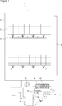
- Figure 1 - is the schematic view of a heat pump dishwasher.
- Figure 2 - is the schematic view of a heat pump system in an embodiment of the present invention.
- the dishwasher (1) comprises a tub (2) wherein the processes of washing, rinsing and drying are performed; at least one rack (3) wherein the items to be washed are placed; at least one spray arm (4) and a circulation pump (5) that provide the delivery of the washing water onto the items to be washed; a drying duct (6) that takes the humid air in the tub (2) out of the tub (2) after the washing process and thus that enables the items washed to be dried, and a heat pump system (7) that is disposed at the lower part of the tub (2) and that provides the heating of the washing water.
- the heat pump system (7) comprises a compressor (8); a condenser (10) that emanates heat by condensing the refrigerant pressurized by the compressor (8) and that is used for heating the washing water by being disposed in a sump (9) wherein the washing water is collected; an evaporator (11) that evaporates the refrigerant so as to draw heat from the outer environment and to transfer the same to the condenser (10); at least one evaporator fan (12) that provides the heat transfer by blowing the outer environment air onto the evaporator (11); an expansion element (13), for example a capillary tube or an expansion valve, that provides the expansion of the refrigerant flowing from the condenser (10) to the evaporator (11), and a return tube (14) that forms the part of the refrigerant flow tubes between the evaporator (11) and the compressor (8); the compressor (8), the condenser (10) the evaporator (11), the evaporator fan (12), the expansion element (13) and
- the condenser (10) of the heat pump system (7) is used for heating the washing water collected in the sump (9), and the evaporator (11) performs the task of completing the refrigerant cycle so as to carry out the function of the condenser (10).
- the heat transfer required for the refrigerant passing through the evaporator (11) to reach the evaporation temperature is realized by the evaporator fans (12).
- the heat pump system (7) is used only for the condenser (10) to heat the washing water, and the evaporator (11) is not required to dry (cool and condense) the washing environment in the tub (2). Since the heat pump system (7) is positioned outside the drying duct (6), the heat pump system (7) has only the "water heating" function, not the function of drying the air in the tub (2).
- the dishwasher (1) of the present invention comprises
- control unit (17) that enables the compressor (9) (the electric motor of the compressor (9)) and the evaporator fan (12) (the electric motor of the evaporator fan (12)) to be operated at variable rotational speed (variable speed, variable capacity, ...), and
- the temperature sensor (15) measures the temperature of the return tube (14) between the evaporator (11) and the compressor (8) while the pressure sensor (16) measures the pressure created by the refrigerant in the return tube (14) (the return tube (14) pressure).
- the capacity of the compressor (8) also increases, and on the other hand, the capacity of the condenser (10) and hence of the evaporator (11) is decreased to balance the heat pump system (7).
- the refrigerant is enabled to quickly change into the vapor phase.
- the refrigerant is enabled to enter from the return tube (14) into the compressor (8) completely in the vapor phase, thus preventing the problem of refrigerant flooding.
- the control unit (17) increases the evaporator fan (12) speed, the evaporator (11) is enabled to draw more heat from the outer environment and to operate at low capacity, thus decreasing the load of the evaporator (11). Consequently, in the evaporator (11), the refrigerant changes to the vapor phase more easily and the problem of refrigerant flooding is prevented.
- the dishwasher (1) comprises a heater (18) that is disposed in front of the evaporator fan (12), that is activated when the temperature of the outer environment falls below a predetermined limit value, for example 21°C, so as to increase the temperature of the air blown from the evaporator fan (12) towards the evaporator (11) and hence the amount of heat drawn by the evaporator (11) from the outer environment, and that enables the refrigerant circulating in the evaporator (11) to more quickly change to the vapor phase so as to prevent the problem of refrigerant flooding (Figure 2).
- a predetermined limit value for example 21°C
- the dishwasher (1) comprises a variable-speed circulation pump (5), and if the problem of refrigerant flooding is detected according to the data received from the temperature sensor (15) and the pressure sensor (16), the control unit (17) decreases the speed of the circulation pump (5) so as to decrease the flow rate of the water heated by the condenser (10), thus enabling the condenser (10) to be operated at low capacity.
- the evaporator (11) is also enabled to be operated at low capacity.
- the refrigerant passing through the evaporator (11) quickly change to the vapor phase and the problem of refrigerant flooding is prevented.
- the method for preventing refrigerant flooding executed by the control unit (17) comprises the steps of
- the method for preventing refrigerant flooding executed by the control unit (17) comprises the steps of
- the method for preventing refrigerant flooding executed by the control unit (17) comprises the steps of
- the refrigerant is enabled to enter the compressor (8) always in the vapor (gas) phase, and the problem of refrigerant flooding, known as the entry of refrigerant in the liquid phase into the compressor (8), is prevented.
- the mixing of the refrigerant with the oil in the compressor (8) is prevented, the viscosity of the oil is maintained, and thus, the movable components in the compressor (8) that are required to be lubricated are prevented from wearing down and being damaged.
- the compressor (8) provides the desired performance in different operating conditions.
Landscapes
- Cleaning By Liquid Or Steam (AREA)
- Washing And Drying Of Tableware (AREA)
Abstract
The present invention relates to a dishwasher (1) comprising a tub (2) wherein the processes of washing, rinsing and drying are performed; at least one rack (3) wherein the items to be washed are placed; at least one spray arm (4) and a circulation pump (5) that provide the delivery of the washing water onto the items to be washed; a drying duct (6) that takes the humid air in the tub (2) out of the tub (2) after the washing process and thus that enables the items washed to be dried, and a heat pump system (7) that is disposed at the lower part of the tub (2) and that provides the heating of the washing water, the present invention further relating to a method for preventing refrigerant flooding.
Description
The present invention relates to a heat pump dishwasher providing the heating of the wash water and to a method for preventing refrigerant flooding.
The heat pump system in the heat pump dishwashers is composed of a compressor that pressurizes the refrigerant and provides the circulation thereof, flow tubes wherein the refrigerant circulates, a condenser, an evaporator, and an expansion element. Like in the conventional dishwashers, the washing program in the heat pump dishwashers is generally composed of the steps of main washing, cold rinsing, hot rinsing and drying. In these steps, the water is heated by the heater in the conventional dishwashers, and is heated by the condenser, that is the "hot" component of the heat pump system, in the heat pump dishwashers. In the heat pump dishwashers, with the compressor compressing and pressurizing the refrigerant, the refrigerant gains high pressure and high temperature. The refrigerant reaching the condenser after leaving the compressor gives off heat to the outer environment, thus the temperature thereof starts decreasing and the refrigerant condenses. The gas at low temperature and high pressure is passed through the throttle valve and the pressure thereof is decreased, and the gas liquefies. Afterwards, the refrigerant at low temperature and low pressure draws heat from the environment while passing through evaporator and changes from the liquid phase into gas phase and vaporizes. Then, the refrigerant reaches the compressor and this cycle is repeated. In the dishwashers, the water is heated with the heat emitted by the condenser. The amount of refrigerant used in the heat pump heating cycle is one of the important parameters that affect the cost/performance of the system. The difference between the temperature of evaporation and condensation depending on the changing ambient conditions affects the temperature and dryness level of the refrigerant at the outlet of the evaporator. Since the refrigerant that reaches the compressor in two phases (liquid + gas), the performance and lifespan of the compressor is affected. In long periods of operation, irreversible damages may occur. The refrigerant leaving the evaporator in the liquid + gas phase without completely evaporating (without completely shifting to the gas phase) is called refrigerant (liquid) flooding. In case the refrigerant is sucked by the compressor in the liquid phase, the cylinder head in the compressor and the gasket acting as the sealing element in the cylinder may be damaged and break to pieces. Therefore, it is critical for the refrigerant to enter the compressor in the gas phase. Moreover, when the refrigerant entering the compressor in the liquid phase mixes with the oil, the viscosity of the oil perceptibly decreases, thus increasing the risk of the wearing down of the compressor bearings. The reason of the refrigerant flooding is that the refrigerant in the cycle does not sufficiently evaporate in the evaporator due to changes in the pressure-temperature relation of the refrigerant, and remains in the liquid phase. Therefore, the refrigerant must completely evaporate before reaching the compressor.
In the state of the art Patent Application No. US2015354879 (A1), a method for preventing refrigerant flooding in a cooling unit is disclosed.
In the state of the art Patent Application No. US2016076542 (A1), a start-up method applied in a compressor wherein refrigerant migration is detected is disclosed.
In the state of the art Patent Application No. WO2006088717 (A2), a method for preventing refrigerant flooding that may occur in the compressor in a heat pump used in cooling systems is disclosed.
In the state of the art Patent No. EP2921098 (B1), a dishwasher is disclosed, wherein the heat pump system is used in the drying process.
The aim of the present invention is the realization of a heat pump dishwasher wherein the problem of refrigerant flooding is eliminated.
The dishwasher realized in order to attain the aim of the present invention comprises a heat pump system that is composed of a compressor, a condenser, an evaporator, refrigerant flow tubes and an expansion element that together perform the refrigerant cycle. The condenser acts as a heater, and the washing water is heated by the condenser placed into a sump.
In the dishwasher of the present invention, if the temperature or pressure of the compressor return tube in the heat pump system is higher than the predetermined threshold values according to the data received from a temperature sensor and a pressure sensor, the control unit decides that the refrigerant coming from the evaporator to the compressor has not completely changed from the liquid phase into vapor phase and increases the compressor speed and/or the evaporator fan speed. Thus, the problem of refrigerant flooding described as the entry of refrigerant in liquid phase into the compressor is eliminated.
In an embodiment of the present invention, if the outer environment temperature falls below a predetermined limit value, for example 21°C, an electric heater disposed in front of the evaporator fan is activated.
In another embodiment of the present invention, if the problem of refrigerant flooding is detected, the control unit decreases the speed of the circulation pump so as to decrease the flow rate of the water heated by the condenser, thus enabling both the condenser and the evaporator to be operated at low capacity.
The heat pump dishwasher realized in order to attain the aim of the present invention is illustrated in the attached figures, where:
Figure 1 - is the schematic view of a heat pump dishwasher.
Figure 2 - is the schematic view of a heat pump system in an embodiment of the present invention.
The elements illustrated in the figures are numbered as follows:
- Dishwasher
- Tub
- Rack
- Spray arm
- Circulation pump
- Drying duct
- Heat pump system
- Compressor
- Sump
- Condenser
- Evaporator
- Evaporator fan
- Expansion element
- Return tube
- Temperature sensor
- Pressure sensor
- Control unit
- Heater
The dishwasher (1) comprises a tub (2) wherein the processes of washing, rinsing and drying are performed; at least one rack (3) wherein the items to be washed are placed; at least one spray arm (4) and a circulation pump (5) that provide the delivery of the washing water onto the items to be washed; a drying duct (6) that takes the humid air in the tub (2) out of the tub (2) after the washing process and thus that enables the items washed to be dried, and a heat pump system (7) that is disposed at the lower part of the tub (2) and that provides the heating of the washing water.
The heat pump system (7) comprises a compressor (8); a condenser (10) that emanates heat by condensing the refrigerant pressurized by the compressor (8) and that is used for heating the washing water by being disposed in a sump (9) wherein the washing water is collected; an evaporator (11) that evaporates the refrigerant so as to draw heat from the outer environment and to transfer the same to the condenser (10); at least one evaporator fan (12) that provides the heat transfer by blowing the outer environment air onto the evaporator (11); an expansion element (13), for example a capillary tube or an expansion valve, that provides the expansion of the refrigerant flowing from the condenser (10) to the evaporator (11), and a return tube (14) that forms the part of the refrigerant flow tubes between the evaporator (11) and the compressor (8); the compressor (8), the condenser (10) the evaporator (11), the evaporator fan (12), the expansion element (13) and the return tube (14) all performing the refrigerant cycle.
Contrary to state of the art embodiments, the condenser (10) of the heat pump system (7) is used for heating the washing water collected in the sump (9), and the evaporator (11) performs the task of completing the refrigerant cycle so as to carry out the function of the condenser (10). The heat transfer required for the refrigerant passing through the evaporator (11) to reach the evaporation temperature is realized by the evaporator fans (12). The heat pump system (7) is used only for the condenser (10) to heat the washing water, and the evaporator (11) is not required to dry (cool and condense) the washing environment in the tub (2). Since the heat pump system (7) is positioned outside the drying duct (6), the heat pump system (7) has only the "water heating" function, not the function of drying the air in the tub (2).
The dishwasher (1) of the present invention comprises
- a temperature sensor (15) and a pressure sensor (16) that are disposed into the heat pump system (7), and
- a control unit (17) that enables the compressor (9) (the electric motor of the compressor (9)) and the evaporator fan (12) (the electric motor of the evaporator fan (12)) to be operated at variable rotational speed (variable speed, variable capacity, ...), and
- that decides that the refrigerant coming from the evaporator (11) to the compressor (8) has not completely changed from the liquid phase into vapor phase if the temperature or pressure values detected in the heat pump system (7) are higher than the predetermined threshold values according to the data received from the temperature sensor (15) and the pressure sensor (16), and that increases the compressor (8) speed and/or the evaporator fan speed (12) (Figure 1, 2).
In an embodiment of the present invention, the temperature sensor (15) measures the temperature of the return tube (14) between the evaporator (11) and the compressor (8) while the pressure sensor (16) measures the pressure created by the refrigerant in the return tube (14) (the return tube (14) pressure).
When the compressor (8) speed is increased by the control unit (17), the capacity of the compressor (8) also increases, and on the other hand, the capacity of the condenser (10) and hence of the evaporator (11) is decreased to balance the heat pump system (7). In the evaporator (11) with decreased capacity and hence decreased load, the refrigerant is enabled to quickly change into the vapor phase. The refrigerant is enabled to enter from the return tube (14) into the compressor (8) completely in the vapor phase, thus preventing the problem of refrigerant flooding.
When the control unit (17) increases the evaporator fan (12) speed, the evaporator (11) is enabled to draw more heat from the outer environment and to operate at low capacity, thus decreasing the load of the evaporator (11). Consequently, in the evaporator (11), the refrigerant changes to the vapor phase more easily and the problem of refrigerant flooding is prevented.
In an embodiment of the present invention, the dishwasher (1) comprises a heater (18) that is disposed in front of the evaporator fan (12), that is activated when the temperature of the outer environment falls below a predetermined limit value, for example 21°C, so as to increase the temperature of the air blown from the evaporator fan (12) towards the evaporator (11) and hence the amount of heat drawn by the evaporator (11) from the outer environment, and that enables the refrigerant circulating in the evaporator (11) to more quickly change to the vapor phase so as to prevent the problem of refrigerant flooding (Figure 2).
In an embodiment of the present invention, the dishwasher (1) comprises a variable-speed circulation pump (5), and if the problem of refrigerant flooding is detected according to the data received from the temperature sensor (15) and the pressure sensor (16), the control unit (17) decreases the speed of the circulation pump (5) so as to decrease the flow rate of the water heated by the condenser (10), thus enabling the condenser (10) to be operated at low capacity. Depending on the decreasing of the condenser (10) capacity, the evaporator (11) is also enabled to be operated at low capacity. Thus, the refrigerant passing through the evaporator (11) quickly change to the vapor phase and the problem of refrigerant flooding is prevented.
In an embodiment of the present invention, the method for preventing refrigerant flooding executed by the control unit (17) comprises the steps of
- operating the compressor (8),
- measuring the temperature of the return tube (14) by means of the temperature sensor (15),
- measuring the pressure of the return tube (14) by means of the pressure sensor (16), and
- gradually increasing the compressor (8) speed if the temperature or pressure of the return tube (14) is higher than the threshold values.
In an embodiment of the present invention, the method for preventing refrigerant flooding executed by the control unit (17) comprises the steps of
- operating the compressor (8),
- measuring the temperature of the return tube (14) by means of the temperature sensor (15),
- measuring the pressure of the return tube (14) by means of the pressure sensor (16), and
- gradually increasing the evaporator fan (12) speed if the temperature or pressure of the return tube (14) is higher than the threshold values.
In an embodiment of the present invention, the method for preventing refrigerant flooding executed by the control unit (17) comprises the steps of
- operating the compressor (8),
- measuring the temperature of the return tube (14) by means of the temperature sensor (15),
- measuring the pressure of the return tube (14) by means of the pressure sensor (16), and
- gradually increasing both the compressor (8) speed and the evaporator fan (12) speed if the temperature or pressure of the return tube (14) is higher than the threshold values.
In the heat pump dishwasher (1) of the present invention, the refrigerant is enabled to enter the compressor (8) always in the vapor (gas) phase, and the problem of refrigerant flooding, known as the entry of refrigerant in the liquid phase into the compressor (8), is prevented. The mixing of the refrigerant with the oil in the compressor (8) is prevented, the viscosity of the oil is maintained, and thus, the movable components in the compressor (8) that are required to be lubricated are prevented from wearing down and being damaged. The compressor (8) provides the desired performance in different operating conditions.
Claims (7)
- A dishwasher (1) comprising a tub (2), a drying duct (6) that enables the washed items to be dried, and a heat pump system (7) that is disposed at the lower part of the tub (2) and that has a compressor (8), a condenser (10), an evaporator (11), at least one evaporator fan (12), an expansion element (13) and a return tube (14) forming the part of the refrigerant flow tubes between the evaporator (11) and the compressor (8), characterized by- a temperature sensor (15) and a pressure sensor (16) that are disposed into the heat pump system (7), and- that enables the compressor (8) and the evaporator (12) to be operated at variable speeds, and that increases the compressor (8) speed and/or the evaporator fan speed (12) if the temperature or pressure values detected in the heat pump system (7) are higher than the predetermined threshold values according to the data received from the temperature sensor (15) and the pressure sensor (16).
- A dishwasher (1) as in Claim 1, characterized by a temperature sensor (15) that measures the temperature of the return tube (14) between the evaporator (11) and the compressor (8) and a pressure sensor (16) that measures the return tube (14) pressure.
- A dishwasher (1) as in Claim 1 or 2, characterized by a heater (18) that is disposed in front of the evaporator fan (12) and that is activated when the temperature of the outer environment falls below a predetermined limit value so as to increase the amount of heat drawn by the evaporator (11) from the outer environment.
- A dishwasher (1) as in Claim 1 or 2, characterized by a variable-speed circulation pump (5), and the control unit (17) that, if the problem of refrigerant flooding is detected according to the data received from the temperature sensor (15) and the pressure sensor (16), decreases the speed of the circulation pump (5) so as to enable the evaporator (11) to be operated at low capacity.
- A method for preventing refrigerant flooding executed by the control unit (17) for a dishwasher (1) as in Claim 1, comprising the steps of:- operating the compressor (8),- measuring the temperature of the return tube (14) by means of the temperature sensor (15),- measuring the pressure of the return tube (14) by means of the pressure sensor (16), and- gradually increasing the compressor (8) speed if the temperature or pressure of the return tube (14) is higher than the threshold values.
- A method for preventing refrigerant flooding executed by the control unit (17) for a dishwasher (1) as in Claim 1, comprising the steps of:- operating the compressor (8),- measuring the temperature of the return tube (14) by means of the temperature sensor (15),- measuring the pressure of the return tube (14) by means of the pressure sensor (16), and- gradually increasing the evaporator fan (12) speed if the temperature or pressure of the return tube (14) is higher than the threshold values.
- A method for preventing refrigerant flooding executed by the control unit (17) for a dishwasher (1) as in Claim 1, comprising the steps of:- operating the compressor (8),- measuring the temperature of the return tube (14) by means of the temperature sensor (15),- measuring the pressure of the return tube (14) by means of the pressure sensor (16), and- gradually increasing both the compressor (8) speed and the evaporator fan (12) speed if the temperature or pressure of the return tube (14) is higher than the threshold values.
Applications Claiming Priority (2)
| Application Number | Priority Date | Filing Date | Title |
|---|---|---|---|
| TR2017/12350A TR201712350A1 (en) | 2017-08-18 | 2017-08-18 | DISHWASHER WITH HEAT PUMP AND COOLANT OVERFLOW PREVENTION METHOD |
| TRA2017/12350 | 2017-08-18 |
Publications (1)
| Publication Number | Publication Date |
|---|---|
| WO2019034372A1 true WO2019034372A1 (en) | 2019-02-21 |
Family
ID=62981240
Family Applications (1)
| Application Number | Title | Priority Date | Filing Date |
|---|---|---|---|
| PCT/EP2018/069762 Ceased WO2019034372A1 (en) | 2017-08-18 | 2018-07-20 | A heat pump dishwasher and method for preventing refrigerant flooding |
Country Status (2)
| Country | Link |
|---|---|
| TR (1) | TR201712350A1 (en) |
| WO (1) | WO2019034372A1 (en) |
Citations (12)
| Publication number | Priority date | Publication date | Assignee | Title |
|---|---|---|---|---|
| FR2304314A1 (en) * | 1975-03-20 | 1976-10-15 | Stierlen Maquet Ag | Space-saving heat recycling system for industrial dishwashers - has compact housing containing heat pump and accessories mounted on machine |
| WO2006088717A2 (en) | 2005-02-16 | 2006-08-24 | Carrier Corporation | Prevention of flooded starts in heat pumps |
| EP2527520A1 (en) * | 2011-05-26 | 2012-11-28 | Electrolux Home Products Corporation N.V. | Articles treatment apparatus having heat pump system with safety element |
| WO2014094854A1 (en) * | 2012-12-20 | 2014-06-26 | Electrolux Home Products Corporation N. V. | Household appliance and method of operating a household appliance |
| WO2015090409A1 (en) * | 2013-12-19 | 2015-06-25 | Electrolux Appliances Aktiebolag | Dishwasher comprising heat pump system |
| WO2015101864A1 (en) * | 2013-12-30 | 2015-07-09 | Indesit Company S.P.A. | Household drying appliance |
| WO2015185086A1 (en) * | 2014-06-02 | 2015-12-10 | Electrolux Appliances Aktiebolag | Domestic appliance |
| US20150354879A1 (en) | 2012-12-27 | 2015-12-10 | Thermo King Corporation | Method of reducing liquid flooding in a transport refrigeration unit |
| US20160076542A1 (en) | 2013-04-12 | 2016-03-17 | Emerson Climate Technologies, Inc. | Compressor with flooded start control |
| WO2016091329A1 (en) * | 2014-12-12 | 2016-06-16 | Electrolux Appliances Aktiebolag | Heat pump arranged in a domestic appliance for heating water |
| CN106852673A (en) * | 2015-12-08 | 2017-06-16 | 杭州三花家电热管理系统有限公司 | Heat-pump-type dish-washing machine |
| EP2921098B1 (en) | 2014-03-17 | 2017-06-28 | Samsung Electronics Co., Ltd. | Dihwasher having drying apparatus |
-
2017
- 2017-08-18 TR TR2017/12350A patent/TR201712350A1/en unknown
-
2018
- 2018-07-20 WO PCT/EP2018/069762 patent/WO2019034372A1/en not_active Ceased
Patent Citations (12)
| Publication number | Priority date | Publication date | Assignee | Title |
|---|---|---|---|---|
| FR2304314A1 (en) * | 1975-03-20 | 1976-10-15 | Stierlen Maquet Ag | Space-saving heat recycling system for industrial dishwashers - has compact housing containing heat pump and accessories mounted on machine |
| WO2006088717A2 (en) | 2005-02-16 | 2006-08-24 | Carrier Corporation | Prevention of flooded starts in heat pumps |
| EP2527520A1 (en) * | 2011-05-26 | 2012-11-28 | Electrolux Home Products Corporation N.V. | Articles treatment apparatus having heat pump system with safety element |
| WO2014094854A1 (en) * | 2012-12-20 | 2014-06-26 | Electrolux Home Products Corporation N. V. | Household appliance and method of operating a household appliance |
| US20150354879A1 (en) | 2012-12-27 | 2015-12-10 | Thermo King Corporation | Method of reducing liquid flooding in a transport refrigeration unit |
| US20160076542A1 (en) | 2013-04-12 | 2016-03-17 | Emerson Climate Technologies, Inc. | Compressor with flooded start control |
| WO2015090409A1 (en) * | 2013-12-19 | 2015-06-25 | Electrolux Appliances Aktiebolag | Dishwasher comprising heat pump system |
| WO2015101864A1 (en) * | 2013-12-30 | 2015-07-09 | Indesit Company S.P.A. | Household drying appliance |
| EP2921098B1 (en) | 2014-03-17 | 2017-06-28 | Samsung Electronics Co., Ltd. | Dihwasher having drying apparatus |
| WO2015185086A1 (en) * | 2014-06-02 | 2015-12-10 | Electrolux Appliances Aktiebolag | Domestic appliance |
| WO2016091329A1 (en) * | 2014-12-12 | 2016-06-16 | Electrolux Appliances Aktiebolag | Heat pump arranged in a domestic appliance for heating water |
| CN106852673A (en) * | 2015-12-08 | 2017-06-16 | 杭州三花家电热管理系统有限公司 | Heat-pump-type dish-washing machine |
Also Published As
| Publication number | Publication date |
|---|---|
| TR201712350A1 (en) | 2019-03-21 |
Similar Documents
| Publication | Publication Date | Title |
|---|---|---|
| US8387273B2 (en) | Heat-pump clothes drying machine | |
| CN102112678B (en) | Condensation dryer with a heat pump and recognition of an impermissible operating state and method for the operation thereof | |
| CN102656314B (en) | Comprise the household electrical appliance of expansion system | |
| EP4140385B1 (en) | Washing appliance | |
| US10724169B2 (en) | Laundry treatment apparatus and method for operating a laundry treatment apparatus | |
| EP2385169A1 (en) | A laundry machine with heat pump system and a method for operating the laundry machine | |
| KR102364677B1 (en) | Control Method for Laundry Treating Apparatus | |
| US11060236B2 (en) | Dryer appliance and method of operating the same based on the relative humidity of drum exit air | |
| US11142863B2 (en) | Controlling refrigerant and air mass flow rate based on moisture extraction rate in a dryer appliance | |
| EP2519686A1 (en) | Heat pump laundry dryer | |
| WO2013045363A1 (en) | Heat pump laundry dryer | |
| JP2018102992A (en) | Refrigeration cycle equipment | |
| EP3256635A1 (en) | Clothes dryer and method for operating a clothes dryer | |
| EP3668365B1 (en) | A heat pump type dishwasher in which refrigerant flooding is prevented | |
| JP2017205651A (en) | Washing and drying machine | |
| WO2013075997A1 (en) | A laundry dryer with a heat pump system | |
| WO2019034372A1 (en) | A heat pump dishwasher and method for preventing refrigerant flooding | |
| EP2976454A1 (en) | Appliance for drying laundry | |
| EP3533920B1 (en) | Clothes drying apparatus with heat pump | |
| JP2016202776A (en) | Washing and drying machine | |
| EP3115500A1 (en) | Household appliance for drying articles | |
| EP2690380A1 (en) | Apparatus including a heat pump and method to operate an apparatus including the heat pump | |
| EP3731717B1 (en) | A heat pump dishwasher with decreased water consumption | |
| CN104508398B (en) | Electrical equipment including heat pump | |
| US20240271355A1 (en) | Laundry treatment appliance including a variable speed blower fan and method of operating the same |
Legal Events
| Date | Code | Title | Description |
|---|---|---|---|
| 121 | Ep: the epo has been informed by wipo that ep was designated in this application |
Ref document number: 18743500 Country of ref document: EP Kind code of ref document: A1 |
|
| NENP | Non-entry into the national phase |
Ref country code: DE |
|
| 122 | Ep: pct application non-entry in european phase |
Ref document number: 18743500 Country of ref document: EP Kind code of ref document: A1 |