JP2017205651A - Washing and drying machine - Google Patents
Washing and drying machine Download PDFInfo
- Publication number
- JP2017205651A JP2017205651A JP2017169103A JP2017169103A JP2017205651A JP 2017205651 A JP2017205651 A JP 2017205651A JP 2017169103 A JP2017169103 A JP 2017169103A JP 2017169103 A JP2017169103 A JP 2017169103A JP 2017205651 A JP2017205651 A JP 2017205651A
- Authority
- JP
- Japan
- Prior art keywords
- washing
- air
- cooling unit
- heat pump
- evaporator
- Prior art date
- Legal status (The legal status is an assumption and is not a legal conclusion. Google has not performed a legal analysis and makes no representation as to the accuracy of the status listed.)
- Granted
Links
- 238000001035 drying Methods 0.000 title claims abstract description 79
- 238000005406 washing Methods 0.000 title claims abstract description 51
- 238000001816 cooling Methods 0.000 claims abstract description 104
- 239000003507 refrigerant Substances 0.000 claims abstract description 86
- 238000010981 drying operation Methods 0.000 claims abstract description 46
- 230000006837 decompression Effects 0.000 claims abstract description 12
- 238000011144 upstream manufacturing Methods 0.000 claims abstract description 6
- XLYOFNOQVPJJNP-UHFFFAOYSA-N water Substances O XLYOFNOQVPJJNP-UHFFFAOYSA-N 0.000 claims description 44
- 230000005484 gravity Effects 0.000 claims description 3
- 230000000694 effects Effects 0.000 description 18
- 238000010586 diagram Methods 0.000 description 13
- 238000001704 evaporation Methods 0.000 description 11
- 230000008020 evaporation Effects 0.000 description 11
- 238000009423 ventilation Methods 0.000 description 8
- 238000007664 blowing Methods 0.000 description 7
- 230000007423 decrease Effects 0.000 description 7
- 238000000034 method Methods 0.000 description 7
- 238000005057 refrigeration Methods 0.000 description 7
- 238000012546 transfer Methods 0.000 description 7
- 230000018044 dehydration Effects 0.000 description 6
- 238000006297 dehydration reaction Methods 0.000 description 6
- 238000005338 heat storage Methods 0.000 description 6
- 239000011232 storage material Substances 0.000 description 6
- 238000009833 condensation Methods 0.000 description 5
- 230000005494 condensation Effects 0.000 description 5
- 238000007791 dehumidification Methods 0.000 description 5
- 239000003599 detergent Substances 0.000 description 5
- 239000006096 absorbing agent Substances 0.000 description 4
- 238000009825 accumulation Methods 0.000 description 4
- 238000004140 cleaning Methods 0.000 description 4
- 238000010438 heat treatment Methods 0.000 description 4
- 239000002826 coolant Substances 0.000 description 3
- 230000008021 deposition Effects 0.000 description 3
- 238000007599 discharging Methods 0.000 description 3
- 239000012530 fluid Substances 0.000 description 3
- 239000007788 liquid Substances 0.000 description 3
- 239000008399 tap water Substances 0.000 description 3
- 235000020679 tap water Nutrition 0.000 description 3
- AZDRQVAHHNSJOQ-UHFFFAOYSA-N alumane Chemical class [AlH3] AZDRQVAHHNSJOQ-UHFFFAOYSA-N 0.000 description 2
- XAGFODPZIPBFFR-UHFFFAOYSA-N aluminium Chemical compound [Al] XAGFODPZIPBFFR-UHFFFAOYSA-N 0.000 description 2
- 229910052782 aluminium Inorganic materials 0.000 description 2
- 238000005520 cutting process Methods 0.000 description 2
- 239000007791 liquid phase Substances 0.000 description 2
- 230000005855 radiation Effects 0.000 description 2
- 238000004381 surface treatment Methods 0.000 description 2
- 239000000725 suspension Substances 0.000 description 2
- 238000010257 thawing Methods 0.000 description 2
- CDOOAUSHHFGWSA-OWOJBTEDSA-N (e)-1,3,3,3-tetrafluoroprop-1-ene Chemical compound F\C=C\C(F)(F)F CDOOAUSHHFGWSA-OWOJBTEDSA-N 0.000 description 1
- FXRLMCRCYDHQFW-UHFFFAOYSA-N 2,3,3,3-tetrafluoropropene Chemical compound FC(=C)C(F)(F)F FXRLMCRCYDHQFW-UHFFFAOYSA-N 0.000 description 1
- 238000013019 agitation Methods 0.000 description 1
- 230000005540 biological transmission Effects 0.000 description 1
- 238000005219 brazing Methods 0.000 description 1
- 238000005260 corrosion Methods 0.000 description 1
- 230000007797 corrosion Effects 0.000 description 1
- 238000005265 energy consumption Methods 0.000 description 1
- 239000012535 impurity Substances 0.000 description 1
- 238000005461 lubrication Methods 0.000 description 1
- 238000012423 maintenance Methods 0.000 description 1
- 239000000463 material Substances 0.000 description 1
- 239000000155 melt Substances 0.000 description 1
- 150000007524 organic acids Chemical class 0.000 description 1
- 239000012071 phase Substances 0.000 description 1
- 238000012545 processing Methods 0.000 description 1
- 230000001737 promoting effect Effects 0.000 description 1
- 239000011347 resin Substances 0.000 description 1
- 229920005989 resin Polymers 0.000 description 1
- 238000012552 review Methods 0.000 description 1
- 238000004904 shortening Methods 0.000 description 1
- 239000011550 stock solution Substances 0.000 description 1
- 238000003860 storage Methods 0.000 description 1
- 239000008400 supply water Substances 0.000 description 1
- 230000037303 wrinkles Effects 0.000 description 1
Images


Abstract
Description
本発明は、乾燥熱源にヒートポンプを搭載した洗濯乾燥機に関する。 The present invention relates to a washing / drying machine having a heat pump mounted on a drying heat source.
洗濯乾燥機は、洗濯から乾燥までを一つの回転槽内で行うものである。ドラム式洗濯乾燥機において、回転槽であるドラムは水平或いは略水平に傾斜して配置された軸周りに回転可能に設置され、ドラムの回転によって、洗い、すすぎ、脱水、乾燥の一連の工程を行うものである。 The washing / drying machine performs washing to drying in one rotating tub. In a drum-type washing and drying machine, a drum as a rotary tub is installed to be rotatable around an axis that is horizontally or substantially inclined, and a series of steps of washing, rinsing, dewatering, and drying are performed by rotating the drum. Is what you do.
乾燥運転時の熱源としては、ヒートポンプ装置を用いた乾燥方式、ヒータによる乾燥方式が使用されている。水分を含んだ衣類を乾燥させるには、湿度が高い空気をドラム内から除去し、除湿及び加熱した空気をドラム内に送り込む乾燥サイクルを連続して行うことが必要である。 As a heat source during the drying operation, a drying method using a heat pump device or a drying method using a heater is used. In order to dry moisture-containing clothing, it is necessary to continuously perform a drying cycle in which high-humidity air is removed from the drum and dehumidified and heated air is fed into the drum.
乾燥熱源としてヒートポンプ装置を用いた洗濯乾燥機においては、圧縮機、循環空気の加熱を行う熱交換器(凝縮器)、減圧手段、循環空気の除湿を行う熱交換器(蒸発器)を配管で順次接続した冷凍サイクルと乾燥用空気を循環させる送風装置を備えている。冷凍サイクルは、圧縮機により高温高圧に圧縮した冷媒を加熱用の熱交換器(凝縮器)に送って空気を加熱し、除湿用の熱交換器(蒸発器)によって空気を除湿して低温低圧となった冷媒を圧縮機に循環させ、再度圧縮するサイクルを繰り返し、送風手段はドラム内の衣類から水分を奪って多湿となった空気を蒸発器によって除湿し凝縮器により加熱して、低湿の空気として再びドラム内に吹き込むことで衣類の乾燥を行っている。 In a washing and drying machine using a heat pump device as a drying heat source, a compressor, a heat exchanger (condenser) for heating the circulating air, a decompression means, and a heat exchanger (evaporator) for dehumidifying the circulating air are connected by piping. A refrigeration cycle sequentially connected and a blower for circulating the drying air are provided. In the refrigeration cycle, the refrigerant compressed to high temperature and high pressure by the compressor is sent to the heat exchanger (condenser) for heating to heat the air, and the air is dehumidified by the heat exchanger for dehumidification (evaporator) to low temperature and low pressure The refrigerant thus obtained is circulated through the compressor and compressed again, and the air blowing means dehumidifies the moisture from the clothes in the drum and dehumidifies the air with an evaporator and heats it with a condenser to reduce the humidity. The clothes are dried by blowing them again into the drum as air.
また、乾燥工程では、空気は衣類から蒸発した水分とともに、衣類から発生したリント (糸くず)を随伴して流動する。比較的大きなリントは循環風路内に設置したフィルタで捕集されるが、フィルタの目よりも細かいリントはフィルタを通過して、ヒートポンプ装置の熱交換器に付着して風路を閉塞させ、風量低下や熱抵抗増大により空気への交換熱量が低下し、乾燥性能の低下の原因となることが分かっている。 In the drying process, air flows along with moisture evaporated from the clothing, and lint generated from the clothing. Relatively large lint is collected by a filter installed in the circulation air passage, but lint finer than the filter eyes passes through the filter, adheres to the heat exchanger of the heat pump device, closes the air passage, It has been found that the amount of heat exchanged into the air is reduced due to a decrease in air volume and an increase in thermal resistance, which causes a decrease in drying performance.
上記のような本技術分野の洗濯乾燥機の背景技術の一例として、特許文献1がある。この特許文献1で示された洗濯乾燥機は、筐体内に弾性支持された水槽と、水槽内に回転可能に設けられ衣類を収納する回転槽と、圧縮機と圧縮された冷媒の熱を放熱する放熱器と高圧の冷媒の圧力を減圧するための絞り手段と減圧されて低圧となった冷媒が周囲から熱を奪う吸熱器とを冷媒が循環するように管路で連結したヒートポンプ装置と送風手段によって前記放熱器で加熱した空気を前記回転槽内へ供給する給気口ホースと送風手段によって前記回転槽内へ供給された空気を前記水槽外へ排出する排気口ホースとを具備し、前記ヒートポンプ装置を構成する熱交換器である放熱器と吸熱器を洗浄する手段を有するものである。これにより、送風回路内に洗濯水の原液や有機酸やリントが浸入しても熱交換器の洗浄手段を有することにより、熱交換器への腐食の影響や風回路として風量低下や熱交換性能低下を受けにくくしているので、ヒートポンプ装置の信頼性、耐久性を向上させ、優れた乾燥性能を保持することが出来るものである、と記載されている。
There exists
上記の従来技術の特許文献1では、風路内の吸熱器(蒸発器)と放熱器(凝縮器)の間に、吸熱器や放熱器に洗浄水を噴出させる洗浄手段を設け、給水弁から給水ホースを介して水道水を供給、あるいは専用のタンクから洗浄水を供給して、熱交換器に付着したリントの洗浄を行っているが、熱交換器前面へのリントの付着を抑止することは考慮されていない。
In
そこで、本発明は、乾燥熱源としてヒートポンプ装置を搭載した洗濯乾燥機において、リントによる熱交換器の閉塞を抑制して、ヒートポンプ装置の信頼性および乾燥性能を向上することを課題とする。 Therefore, an object of the present invention is to improve the reliability and drying performance of a heat pump device by suppressing clogging of the heat exchanger due to lint in a washing dryer equipped with a heat pump device as a drying heat source.
上記の課題を解決するために、本発明の洗濯乾燥機は、回転ドラムと、該回転ドラムを内包する外槽と、ヒートポンプ装置と、フィルタと、送風ファン、及びこれらを接続する循環風路を備えた洗濯乾燥機において、前記ヒートポンプ装置は、圧縮機と、冷媒の熱を空気に放熱する凝縮器と、減圧手段と、空気から吸熱する蒸発器とを順次接続した冷媒回路で構成され、
前記ヒートポンプ装置の蒸発器上流に乾燥運転時の循環空気の露点温度よりも低い温度となる冷却部を設けことを特徴とする。
In order to solve the above problems, a washing and drying machine according to the present invention includes a rotating drum, an outer tub containing the rotating drum, a heat pump device, a filter, a blower fan, and a circulation air path connecting them. In the washing and drying machine provided, the heat pump device is configured by a refrigerant circuit in which a compressor, a condenser that radiates heat of the refrigerant to the air, a decompression unit, and an evaporator that absorbs heat from the air are sequentially connected.
A cooling unit having a temperature lower than the dew point temperature of the circulating air during the drying operation is provided upstream of the evaporator of the heat pump device.
本発明によれば、外槽からフィルタを経て乾燥熱源であるヒートポンプ装置へ至る風路の蒸発器の上流に、乾燥運転時の循環空気の露点温度よりも低い温度となる冷却部を配置している。このような構成とすることで、循環空気に随伴したリントは冷却部上で循環空気中の水分の結露とともに捕集されるため、蒸発器の前面へのリントの付着を抑制することが可能となる。この結果、蒸発器前面でのリント堆積による閉塞や通風抵抗の増加を防ぐことで、ヒートポンプ装置の信頼性を向上することが可能となる。また、乾燥運転中の風量が確保できるため、消費電力低減及び、除湿性能を良好とすることによる乾燥性能向上を両立した洗濯乾燥機を提供することができる。 According to the present invention, a cooling unit having a temperature lower than the dew point temperature of the circulating air during the drying operation is arranged upstream of the evaporator of the air passage from the outer tank to the heat pump device that is the drying heat source through the filter. Yes. By adopting such a configuration, lint accompanying the circulating air is collected along with condensation of moisture in the circulating air on the cooling unit, so that it is possible to suppress adhesion of lint to the front surface of the evaporator. Become. As a result, it is possible to improve the reliability of the heat pump device by preventing the blockage due to lint deposition on the front surface of the evaporator and the increase in ventilation resistance. Moreover, since the air volume during the drying operation can be ensured, it is possible to provide a washing and drying machine that achieves both reduced power consumption and improved drying performance by improving the dehumidifying performance.
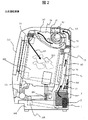
以下、本発明に係る実施例1について説明する。図1は本実施例の洗濯乾燥機20の筺体の一部を切断して内部構造を示す斜視図、図2は本実施例の洗濯乾燥機20の内部構造を示す側面図、図3は本実施例の洗濯乾燥機20の内部構造を示す背面図、図4は本実施例の洗濯乾燥機20のヒートポンプ装置の構成を示す模式図、図5はー般的な洗濯乾燥機のヒートポンプ装置の構成を示す模式図である。 Example 1 according to the present invention will be described below. FIG. 1 is a perspective view showing an internal structure by cutting a part of the casing of the washing / drying machine 20 of this embodiment, FIG. 2 is a side view showing the internal structure of the washing / drying machine 20 of this embodiment, and FIG. 4 is a rear view showing the internal structure of the washing / drying machine 20 according to the embodiment, FIG. 4 is a schematic view showing the configuration of the heat pump apparatus of the washing / drying machine 20 according to this embodiment, and FIG. 5 shows the heat pump apparatus of a general washing / drying machine. It is a schematic diagram which shows a structure.
本実施の形態例の洗濯乾燥機20において、外槽101は洗濯乾燥機筺体100のベース105上にサスペンション104により弾性支持されている。外槽101の内側には前面が開放され、回転自在に軸支持された回転ドラム103が配置され、回転ドラム103は外槽101の背面に設けられた駆動モータ107の駆動力により回転する。洗濯乾燥機20の前面側には開口部106が形成され、開口部106を開閉するドア111が設けられている。ユーザは、開口部106から、衣類200を回転ドラム103内部に投入し、洗濯乾燥が終了した衣類200をとりだすことが出来る。
In the washing / drying machine 20 of the present embodiment, the
外槽101の上部には、洗濯乾燥機20の前面から見て左側前方に洗剤投入手段108が設けられ、左側後方には、給水ユニット112が設置されている。また、外槽101上部には乾燥手段の構成要素であるリントフィルタ90、送風ファン8が設置されている。送風ファン8は、遠心式の多翼ファンないしはターボ送風機である。
また、外槽101を構成する外槽前面カバー102の右側上部には、回転ドラム103内への循環空気の吹出口14が設置されている。
In the upper part of the
In addition, an
外槽101の背面部には、循環空気を回転ドラム103から排出する排出口15を備え、排出口15は排気ダクト73によりフィルタケース91に接続されている。外槽101とダクト等の接続は、運転時の振動の伝達を抑制するためにゴム製のジャバラ等を介して接続している。
The rear surface of the
次にヒートポンプ装置1の構成と動作について説明する。図3は本実施例の洗濯乾燥機20の内部構造を示す背面図で、ヒートポンプ装置1の冷媒回路16の構成と循環風路の構成を示している。図4に示すように、ヒートポンプ装置1は、圧縮機2と、空気への放熱用熱交換器(凝縮器3)、減圧装置5(膨張弁等)と、空気の除湿用熱交換器(蒸発器4)とを備え、これらの機器を冷媒配管6により順次接続してなる冷媒回路16を、樹脂製のケーシング18内に収納したものである。冷媒は図中R1で示した矢印の方向に、圧縮機2、凝縮器3、減圧装置5、蒸発器4の順に流れ、再度圧縮機に戻る。
Next, the configuration and operation of the
ヒートポンプ装置1を構成する蒸発器4、凝縮器3は空気と熱交換を行うため、一般的に積層したアルミフィンに伝熱管を貫通するように取り付けたクロスフィンチューブ式の熱交換器が用いられることが多い。以降、凝縮器と蒸発器を合わせて熱交換器と呼ぶ。
Since the evaporator 4 and the
ヒートポンプ装置1のケーシング18は、下部ケーシング(図示せず)と上部ケーシング(図示せず)に分離可能な構成である。熱交換器(蒸発器4、凝縮器3)は側面側に流れる空気を阻害するように、上部ケーシングと下部ケーシングの間に挟み込むように設置され、空気の循環風路を形成する。
The
圧縮機2は防振ゴム等を介して、下部ケーシングに設置される。冷媒配管6は、圧縮機2の回転振動の伝搬により破断することを防ぐため、蛇行した状態で放熱用の凝縮器3と除湿用の蒸発器4のそれぞれと接続されている。
The
圧縮機2は、制御が可能な圧縮機を用い、例としては、ピストン式、ロータリー式、スクロール式等を用いることができる。インバータ制御により、低速から高速まで回転速度が可変である。
As the
また、冷媒が液相で圧縮機2に戻ると、圧縮機2の摺動面での潤滑不良により信頼性を低下させることがある。これを抑止するために、冷媒の吸入側にアキュムレータ(図示せず)を設けるとよい。
Further, when the refrigerant returns to the
圧縮機2から吐出された高温高圧のガス冷媒は、凝縮器3へ流入し、循環空気に放熱することにより凝縮して液化する。液化した冷媒は、所定の開度に調整された膨張弁(減圧装置5)により減圧され、低温低圧の気液二相状態となり、蒸発器4へ流入する。そして循環空気から吸熱することにより蒸発して気化する。気化した冷媒は、圧縮機2に吸入され、圧縮機2により再び圧縮され高温高圧のガス冷媒となる。このようにしてヒートポンプ装置1が形成される。
前記冷媒回路16内には冷媒が封入され、冷媒として例えば、HFC単一冷媒、HFC混合冷媒、HFO‐1234yf、HFO‐1234ze、自然冷媒(例えばCO2冷媒)等を用いることができる。
The high-temperature and high-pressure gas refrigerant discharged from the
A refrigerant is sealed in the
ヒートポンプ装置1は、外槽101の下部、洗濯乾燥機筺体100の後方のベース105上に設置してある。循環空気は回転ドラム103から排出口15を経て排出され、リントフィルタ90通過後、外槽101上部から下部に向かって入口側流路70を経由してヒートポンプ装置1に流入する。ヒートポンプ装置1において除湿及び加熱された循環空気は、外槽101下部から上部に向かって循環空気が流れる出口側流路71から、送風ファン入口ダクト72を通り、送風ファン8に接続され、外槽101の前面上部に設けた吹出し口14により回転ドラム103内に吹き込まれる。
The
ヒートポンプ装置1を構成する蒸発器4は回転ドラム103内の衣類200から蒸発した水分を含んだ高湿の空気を除湿し、凝縮器3では蒸発器4で吸熱した熱量と圧縮機2の熱量を循環空気に放熱する。一般的にフィンチューブ式熱交換は積層したアルミフィンの表面にスリットを切り起こすことや、折り目を加工すること、フィンピッチを詰めること等で伝熱面積を増加させ、空気流に対する前縁効果により伝熱性能を向上させている。また、アルミフィンの表面には親水性処理等の表面処理が施され、フィン表面に結露した水分を流し落としやすくする構成となっている。
The evaporator 4 constituting the
乾燥運転時には蒸発器4は循環空気の露点温度以下となるように制御されるため、蒸発器4を構成するフィンの表面には、循環空気中の水分が結露して付着する。 During the drying operation, the evaporator 4 is controlled so as to be equal to or lower than the dew point temperature of the circulating air. Therefore, moisture in the circulating air is condensed and attached to the surfaces of the fins constituting the evaporator 4.
この結露した除湿水が蒸発器4の下部に流れ落ちずにフィンのスリット間やフィンとフィンの間に保持された状態、すなわち水切り性が不良であると、循環空気にとって通風抵抗となり、ファンの動力を増大させることや、水膜が熱抵抗となり、伝熱性能を低下させる懸念がある。ここで、通風抵抗とは、熱交換器(蒸発器4、凝縮器3)の前後に圧力計を設け、熱交換器(蒸発器4、凝縮器3)を通過する空気の圧力差を測定したものである。 If the condensed dehumidified water does not flow down to the lower part of the evaporator 4 and is held between the fin slits or between the fins, that is, if the drainage is poor, ventilation resistance is generated for the circulating air, and the fan power There is a concern that the water film becomes a thermal resistance and the heat transfer performance is lowered. Here, the ventilation resistance is a pressure gauge provided before and after the heat exchanger (evaporator 4 and condenser 3), and the pressure difference of the air passing through the heat exchanger (evaporator 4 and condenser 3) is measured. Is.
図3で示すように循環空気は外槽101背面の排出口15から排出され、排気ダクト73を経由してリントフィルタ90に至る。リントフィルタ90では、洗濯乾燥時に衣類200から発生した糸屑(リント)がリントフィルタ90のメッシュに捕集される。しかし、すべてのリントをリントフィルタ90において取り除くことは困難であり、フィルタメッシュをすり抜けた細かいリントは、入口側流路70を通って、ヒートポンプ装置1に到達し、風路の上流にある蒸発器4の前面、あるいはフィン間に付着する可能性がある。蒸発器4に付着したリントが堆積していくと、熱交換器(蒸発器4、凝縮器3)へ流れる空気流を阻害するため、所定の交換熱量が得られないことによる性能低下や、風路の圧力損失が増大するために風量が低下して乾燥時間が長くなるため消費電力が増大する等の課題がある。
As shown in FIG. 3, the circulating air is discharged from the
そこで、本実施例のヒートポンプ装置1の蒸発器4の上流側に乾燥運転時の循環空気の露点温度よりも低い温度となる冷却部17を設ける構造とした。
Therefore, a structure is provided in which a
冷却部17の温度は循環空気の露点温度よりも低く設定されているため、循環空気中の水分は冷却部17表面で水滴状、あるいは液膜状に結露する。循環空気とともに流れてきた細かいリントは、冷却部17表面上の水滴あるいは液膜と接触して捕集されるため、蒸発器4へ流れ込むことを抑制される。
Since the temperature of the cooling
上述の構成により、循環空気に随伴して流れるリントを冷却部17上で捕集して熱交換器(蒸発器4、凝縮器3)への流入を抑制することが出来るため、蒸発器4前面及びフィン間へのリントの堆積を防ぐことができる。したがってフィンの閉塞による循環風量の低下や、風量を維持するためのファン入力の増加を抑制し、さらに、乾燥運転時間の増加を抑制することができるため、乾燥運転時の消費電力量の増大を抑えて、省エネルギー化を図る効果を得ることができる。
With the above-described configuration, the lint flowing along with the circulating air can be collected on the
冷却部17への冷熱の供給は、ヒートポンプ装置1の冷媒回路16を冷却部17設置箇所まで配設することで行われる。冷媒配管6が冷却部17として機能する場合を除き、冷媒配管6からの冷熱を冷却部17に効率よく伝えるためには、冷媒配管6と伝熱面を熱的に接触させる必要がある。熱的に接触させる方法としては、冷却部17と冷媒配管6をロウ付けする方法や、冷却部17と冷媒配管6との間に熱伝導性の高い材料を充填して接触熱抵抗を低減させる方法などが挙げられるが方法を限定するものではない。
The supply of cold heat to the
また、冷却部17の表面は、表面に結露した水滴によりリントを捕集するものであるため、水滴を保持しやすい構造が望ましい。例えば、表面に親水性処理を施すことで冷却部17表面に液滴を生成しやすくなる。このような構成とすることで、リントを捕集した液滴が一定の大きさ以上に成長した場合、自重で流下し冷却部17表面からリントを含んだ水滴は除去されて、排出されることになる。
Moreover, since the surface of the cooling
また冷却部17の構造の別の例として、冷却部17の冷媒配管6の周囲に潜熱蓄熱材(図示せず)を配置し、冷媒配管、潜熱蓄熱材及び冷却部17は熱的に接触している構成とする。このように、潜熱蓄熱材から、冷却部17へ冷熱が供給される構成とすることで、冷媒配管6から冷却部17への冷熱の供給が停止した場合でも、ヒートポンプ装置1の運転中に潜熱蓄熱材に蓄熱された冷熱により、冷却部17は一定時間低温を保つことが可能となる。
As another example of the structure of the cooling
また、冷却部17の表面温度を蒸発器4の冷媒温度よりも低く設定する、例えば0℃以下に制御することで、冷却部17の表面に霜、氷を生成することが可能である。
Moreover, frost and ice can be generated on the surface of the cooling
このような構成にすると、循環空気中のリントは霜(氷)と接触して捕集され、霜(氷)はリントを閉じ込めた状態で成長するため、捕集されたリントが循環空気中に流れ出すことを防ぐことが出来る。 With this configuration, lint in the circulating air is collected in contact with the frost (ice), and the frost (ice) grows in a state where the lint is confined, so that the collected lint is in the circulating air. It can be prevented from flowing out.
また、リントを含んだ霜(氷)は、ヒートポンプ装置1の運転を停止し、冷却部17への冷熱供給が終了すれば、融解して自重で流下し、蒸発器4の除湿水と同様に排水部18aから排出される。
Further, the frost (ice) containing lint melts and flows down by its own weight when the operation of the
さらに冷却部17に給水ユニット112から冷却部17への給水手段(図示せず)を設けることで冷却部17表面に霜(氷)を生成することが可能となり、冷却部17上で効果的にリントを捕捉することが出来る。
Furthermore, by providing water supply means (not shown) from the
また、給水ユニット112から冷却部17への給水により、冷却部17上に付着したリントを水により洗い流すことが可能となる。冷却部17から除去されたリントは、蒸発器4の除湿水と同様に除湿水の排出手段18aにより、ヒートポンプ装置1のケーシング18から排出されるため、蒸発器4の前面に付着するリントの量を抑制することが出来る。給水手段112から冷却部17に給水される流体は、水道水や、洗剤等を溶解した水等、表面に付着したリントを洗い流す用途に適したものであればよい。
In addition, by supplying water from the
図6から図9は、冷却部17を設けた本発明の一実施形態例のヒートポンプ装置の冷媒回路を示す模式図である。
6 to 9 are schematic views showing a refrigerant circuit of a heat pump device according to an embodiment of the present invention in which a
図6において冷却部17へ至る冷媒回路は、凝縮器3を経て蒸発器4へ流れる経路と、冷却部17に流れる経路の2方向に分岐して流れた後に合流する。膨張弁5aを経由して蒸発器4へ流れた冷媒はバルブV1を通過し、膨張弁5bを経由して冷却部17へ流れた冷媒はバルブV2を通過する構成となっている。冷却部17と、蒸発器4はそれぞれ膨張弁(5a、5b)とバルブ(V1、V2)によって仕切られているため、冷却部17、蒸発器4を併用すること、あるいはどちらか一方を使用することが出来るため、必要に応じて運転パターンを変更可能となる。
In FIG. 6, the refrigerant circuit that reaches the cooling
例えば、冷却部17と蒸発器4を併用した場合は、冷却部17でリントを捕集しながら、蒸発器4において、循環空気の除湿を行うことが出来る。
For example, when the cooling
また、前述した実施の形態のように、冷却部17に配置した潜熱蓄熱材に蓄冷する場合は、蒸発器4を用いずに冷却部17のみを使用しても良い。
Further, as in the above-described embodiment, in the case where the latent heat storage material disposed in the
さらに、膨張弁(5a、5b)とバルブ(V1、V2)の開閉操作により、使用しない側の冷媒配管に一時的に冷媒を貯留しておくことも可能である。 Further, the refrigerant can be temporarily stored in the refrigerant pipe on the unused side by opening / closing the expansion valves (5a, 5b) and the valves (V1, V2).
また、図7の冷媒回路は、冷却部17を通過後に蒸発器4に至る冷媒の経路と、冷却部17をバイパスする冷媒の経路に切り替えることが出来る。このような構成とすることで、前述した実施例のように冷却部17に配置した潜熱蓄熱材に蓄冷した後に、冷却部17を切り離して除湿を行う運転が可能となる。
In addition, the refrigerant circuit of FIG. 7 can be switched between a refrigerant path that reaches the evaporator 4 after passing through the
図8の冷媒回路は、冷却部17を蒸発器4の後流に配置している。このような構成にすることで、冷媒は同一の流量で蒸発器4に続いて冷却部17を流れるため、冷媒の圧力損失の増加により蒸発圧力が低下して蒸発温度が低下する。これにより、冷却部17の冷媒温度を蒸発器4の冷媒温度よりも低くして運転することができる。
In the refrigerant circuit of FIG. 8, the cooling
さらに、図9の冷媒回路は、蒸発器4a、冷却部17、蒸発器4bの順に配置した例である。このような構成にすることで、冷媒は同一の流量で蒸発器4aに続いて冷却部17を流れるため、冷媒の圧力損失の増加により蒸発圧力が低下して蒸発温度が低下する。これにより、冷却部17の冷媒温度を蒸発器4aの冷媒温度よりも低くした運転が可能となる。さらに蒸発器4bにより循環空気と熱交換を行うことにより、圧縮機2の入口で、冷媒の過熱度を増加させて、圧縮機2に冷媒が液相で流入することを防ぎ、圧縮機2を保護することが可能となる。
Furthermore, the refrigerant circuit of FIG. 9 is an example in which the evaporator 4a, the cooling
上述の構成により、冷却部17でのリントの除去と循環空気の除湿を効果的に行うことが可能となり、熱交換器(蒸発器4、凝縮器3)へのリント堆積を防ぐことによるファン動力の増加を抑制し、乾燥運転時の省エネルギー化を図ることが出来る。
With the above-described configuration, it is possible to effectively remove lint in the
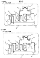
図10には本発明の一実施形態例のヒートポンプ装置の冷媒回路を模式的に示している。図10aは乾燥運転時の冷媒の流れを示し、図10bは四方弁30により冷媒回路を切り替えた場合の冷媒の流れを示している。
FIG. 10 schematically shows a refrigerant circuit of a heat pump device according to an embodiment of the present invention. FIG. 10 a shows the refrigerant flow during the drying operation, and FIG. 10 b shows the refrigerant flow when the refrigerant circuit is switched by the four-
図10bに示した除霜運転の冷媒回路は、圧縮機2、四方弁30を通過後に、冷却部17、蒸発器4の二方向に分岐後、合流して凝縮器3、四方弁30を通過して圧縮機2に戻る構成となっている。四方弁30により冷媒の流れは逆になっているため、冷却部17及び蒸発器4には高温高圧のガス冷媒が流入して凝縮器として機能する。このため、冷却部17上の生成された霜や氷は融解し、蒸発器4表面の水滴は乾燥する。この除霜運転を行うことで、乾燥運転終了時の冷却部17、蒸発器4は乾燥した状態となり、伝熱面に残留した水滴や不純物による臭い発生を抑制する効果を得る。
The refrigerant circuit for the defrosting operation shown in FIG. 10 b passes through the
また図10は、一例として図6に示した冷媒回路に四方弁30を設置した構成となっているが、構造を限定するものではなく、例えば図7から図9の冷媒回路に四方弁30を配置した構成であってもよく、同様の効果を得ることが出来る。
FIG. 10 shows a configuration in which the four-
前述のように回転ドラム103から排出された循環空気は、乾燥の進行に伴い、衣類200から発生したリントを随伴して流れている。ヒートポンプ装置1に用いられているフィンチューブ式熱交換器は、アルミニウム製フィンを多数積層した構造となっているため、リントが蒸発器4の前面やフィン間に堆積すると、循環空気の風路抵抗となり、交換熱量が減少する恐れがある。即ち、リントフィルタ90でのリントの効果的な捕捉はヒートポンプ装置1にとって重要である。しかしながら、リントフィルタ90においてリントを捕集するためにフィルタメッシュを細かくしすぎれば、リントフィルタ90の閉塞により風路抵抗が増大し、ファンの動力が増大し、省エネルギー性が低下する場合や、循環空気量が減少する懸念がある。
As described above, the circulating air discharged from the
上述のような課題を解決するために、本実施例の洗濯乾燥機20は排気ダクト73に冷却部17を設置する構成とした。このような構成とすることで、回転ドラム103から排気された循環空気は、冷却部17上で結露して、随伴してきたリントを結露水に残してリントフィルタ90に流入する。従ってリントフィルタ90に流入するリントの量を抑制するためリント堆積による通風抵抗増加を防ぐことが可能となり、ファンの消費電力量の増加を抑制可能である。
In order to solve the above-described problems, the washing / drying machine 20 of the present embodiment is configured to install the
さらに、外槽101上部に設けられた給水ユニット112から入口側流路70への給水手段(図示せず)を設けておけば、冷却部17に付着したリントを水により洗い流すことが可能となる。
Furthermore, if water supply means (not shown) from the
また、冷却部17に給水ユニット112から給水することで、冷却部17表面に霜(氷)を生成することが可能となり、冷却部17上で効果的にリントを捕捉することが出来る。
In addition, by supplying water from the
上述の構成により、循環空気に随伴して流れるリントを冷却部17上で捕集して熱交換器(蒸発器4.凝縮器3)への流入を抑制することが出来るため、蒸発器4前面及びフィン間へのリントの堆積を防ぐことができる。したがってファン入力の増加を抑制することができ、乾燥運転時の消費電力量の増大を抑えて、省エネルギー化を図る効果を得ることができる。
With the above-described configuration, the lint flowing along with the circulating air can be collected on the
ヒートポンプ装置1の入口側流路70の内表面に表面処理を施し、フィルタメッシュを通過したリントが入口側流路70の内表面に付着しやすい構成とし、さらに外槽101上部に設けられた給水ユニット112から入口側流路70への給水手段(図示せず)を設けておけば、入口側流路70内表面に付着したリントを水により洗い流すことが可能となる。
A surface treatment is applied to the inner surface of the inlet-
さらに、上述の給水手段は冷却部17へ給水することが可能であるため、冷却部17に付着したリントを効果的に洗い流すことが可能である。
Furthermore, since the above-mentioned water supply means can supply water to the
入口側流路70の内面から除去されたリントは、蒸発器4の除湿水とともにドレンの排出手段(図示せず)により、ヒートポンプ装置1のケーシング18から排出されるため、蒸発器4の前面に付着するリントの量を抑制することが出来る。また、給水手段112から入口側流路70に給水される流体は、水道水や、洗剤等を溶解した水等、入口側流路70の内表面に付着したリントを洗い流す用途に適したものであればよい。
The lint removed from the inner surface of the inlet-
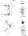
図11は本発明の一実施形態例に係わる洗濯乾燥機の冷却部と風路の構成を示す模式図を示している。 FIG. 11: has shown the schematic diagram which shows the structure of the cooling part and air path of the washing-drying machine concerning one example of embodiment of this invention.
図11aは、冷却部17を排気ダクト73に設置した例を示している。図中冷却部17は循環空気が外槽101から排出された直後の曲がり部と、リントフィルタ90へ向かう曲がり部に設置されている。このような構成にすることで、循環空気は曲がり部により流れ方向が変わるために冷却部17に接触しやすくなる。また、冷却部17で結露した水分及びリントは、排気ダクト73内を重力により流下して、外槽101に流れ込み、排水ホース110から排出される。
FIG. 11 a shows an example in which the
上記の構成により、冷却部17でのリントの除去と循環空気の除湿を効果的に行うことが可能となり、リントの堆積によるリントフィルタ90の通風抵抗の上昇を抑制して循環風量の低下を抑制できるため、乾燥運転時間が増加することによる消費電力量の増大を抑制することが可能となる。
With the above configuration, it is possible to effectively remove lint and dehumidify the circulating air in the
図11bは、冷却部17をヒートポンプ装置1の入口部に設置した例を示している。図中冷却部17は、入口側流路70からヒートポンプ装置1へ向かう循環風路の曲がり部に設置されている。このような構成とすることで循環空気は曲がり部により流れ方向が変わるために冷却部17に接触しやすくなる、また、冷却部17で結露した水分及びリントは、重力により流下してヒートポンプ装置1のケーシング18に流れ込み、排水部18aから排出される。
FIG. 11 b shows an example in which the
図11cから図11dは、冷却部17を入口側流路70に設置した例を示している。図中、冷却部17は、入口側流路70の長手方向の略中心部に配置されている。
FIGS. 11 c to 11 d show an example in which the
図11cにおいて冷却部17は、ねじりテープ状の形状で入口側流路70に設置されているため、循環空気は冷却部17の表面に沿って旋回を伴って流れ、冷却部17の表面で結露し、リントは液滴に捕集される。結露した水分とリントは、冷却部17に沿って流れ、入口側流路70の内面を流下してヒートポンプ装置1のケーシング18に流れ込み、排水部18aから排出される。
In FIG. 11 c, since the cooling
図11dにおいて冷却部17は、放射状に形成されている。循環空気は冷却部17で分割された流路を通過するため、冷却部17の表面で結露し、リントは液滴に捕集される。結露した水分とリントは、冷却部17に沿って流れ、入口側流路70の内面を流下してヒートポンプ装置1のケーシング18に流れ込み、排水部18aから排出される。
In FIG. 11d, the cooling
上記の構成により、冷却部17でのリントの除去と循環空気の除湿を効果的に行うことが可能となり、ヒートポンプ装置1へのリントの流入を抑制し、蒸発器4の前面でのリント堆積による通風抵抗の増大を抑制することが出来る。したがって、乾燥運転時の風量低下や、風量維持に起因する消費電力量の増大を防ぐことができるため、省エネルギー化を図る効果を得る。
With the above configuration, it is possible to effectively remove the lint in the
本実施例の洗濯乾燥機20は、制御装置13を備えている。制御装置13は、少なくとも洗濯運転、乾燥運転、あるいは洗濯乾燥運転の開始時に回転ドラム103内に投入された衣類200の容量のセンシングを行い、判定値に基づいて、投入する洗剤量、運転時間を決定し、表示部に表示するが、運転途中においても、再度容量のセンシングを行うことで、運転時間の見直しを行い、衣類の容量に応じた最適な運転時間と運転工程を選択し、乾燥消費電力量の増大を抑制することが可能となる。
The washing / drying machine 20 of this embodiment includes a
さらに、ヒートポンプ装置1は、熱交換器(凝縮器3、蒸発器4)を流れる冷媒温度を検出するセンサを備えている。図3には冷媒配管6に温度センサT1、T2、T3を設置した一例を示している。通常、冷凍サイクルにおいては運転状態を把握するために、冷媒配管6や熱交換器(凝縮器3、蒸発器4)に圧力センサや温度センサを設置している。一例として、センサ類は圧縮機2の吸込側、吐出側、熱交換器(蒸発器4、凝縮器3)の出入口、膨張弁(減圧装置5)前などに設置され、検出量により冷凍サイクルの状態を表すモリエル線図を推定し、冷凍サイクルの制御が行われている。本実施例の冷媒回路16では温度センサで冷凍サイクルの性能を推定しているが、圧力センサを取り付けた構成としてもよい。圧力データを制御装置13で利用することが出来れば、冷凍サイクルの成績係数(COP)が最適となるように制御可能となり、乾燥運転時の消費電力量を低減することが可能となる。
Furthermore, the
また、乾燥運転時の循環空気は、回転ドラム103から排出され、リントフィルタを90通過後、ヒートポンプ装置1により、除湿・加熱されて送風ファン8により再び回転ドラム103内に吹きこまれる。本実施例の洗濯乾燥機20は、上記の循環空気の状態をモニターするために、温度及び湿度センサ(図示せず)を備えている。乾燥運転時に回転ドラム103への吹出口14、回転ドラム103からの排出口15での温度及び湿度データを把握することにより、衣類200からの水分の概略の蒸発量を推定し、衣類200の乾燥状態を推測することで、乾燥運転時間を最適に設定することが可能となる。このため、乾燥運転時の消費電力量を抑え、省エネルギー化を得ることができる。
The circulating air during the drying operation is discharged from the
循環空気の温湿度データからは、循環空気の露点温度を算出することができる。ヒートポンプ装置1の冷凍サイクルの運転条件として、循環空気のヒートポンプ入口での露点温度を把握することが出来れば、蒸発器4を流れる冷媒温度が循環空気の露点温度以下となるように制御することで、除湿性能を向上させることが出来る。冷却部17の温度は蒸発器4の冷媒温度よりも低くする制御を行うことで、循環空気に随伴されて流れるリントを冷却部17で捕集することが可能となる。
From the temperature and humidity data of the circulating air, the dew point temperature of the circulating air can be calculated. As an operating condition of the refrigeration cycle of the
また、制御装置13は、衣類200の容量に基づいて決定された運転工程により、ヒートポンプ装置1の膨張弁5の開度、圧縮機2の回転速度、送風ファン8の回転速度を制御する。乾燥運転時に衣類200から蒸発させるべき水分量は、衣類200の種類及びその重量と、脱水後の衣類の重量から推定される。推定された水分を衣類200から蒸発させるために、ヒートポンプ装置1の凝縮温度、及び蒸発温度及び冷媒の循環量を最適に制御する必要がある。
Further, the
通常、凝縮温度は回転ドラム103内へ吹き込む空気温度よりも高く設定し、蒸発温度は回転ドラム103から吹出された空気の露点温度以下に設定する。この時、蒸発温度を低くしすぎると、空気の除湿は促進されるが、循環空気が必要以上に冷却され、凝縮器3での加熱量が不足する場合がある。このような場合、冷媒循環量を増加させて凝縮温度を高くすることで対応可能な場合があるが、同時に圧縮機2の消費電力が増加するため、乾燥の消費電力量が増加し、乾燥効率は低下することになる。
Usually, the condensing temperature is set higher than the temperature of air blown into the
上述のように乾燥運転時の消費電力量を低減するには、ヒートポンプ装置1において消費電力量の多くを占める圧縮機2の消費電力量と、送風ファン8の消費電力量を低減することが有効であり、乾燥運転時間の最適化を図ることで、乾燥運転時の消費電力量を抑え、省エネルギー化を図る効果を得ることができる。
In order to reduce the power consumption during the drying operation as described above, it is effective to reduce the power consumption of the
さらに、図1から図3に示しているように、送風ファン8から回転ドラム103への吹出口14への風路の長さを短くする構成とすることで、吹出口14から、高速、高風量の空気を衣類に吹き付けることが可能となり、乾燥運転時に高い仕上がり性を得る効果がある。
Further, as shown in FIGS. 1 to 3, the length of the air path from the
加えて、送風ファン8により昇圧された速い流速の空気が流れる風路を構成する吹出しダクト74から吹出口14までを短い風路にでき、圧力損失の増加を抑制可能である。このため、送風ファンモータ81の消費電力を低くできるので、乾燥運転時の消費電量を抑えた高い省エネルギー性を有することが可能である。
In addition, it is possible to make a short air path from the
ここで、吹出口14の位置は必ずしも前面側の上部でなくても良い。例えば、吹出口14を回転ドラム103の背面側に設けた場合には、吐出口14の面積を大きくし易いので、大風量での乾燥により乾燥性能を高めることが可能となる。また、回転ドラム103を斜めに配置する洗濯乾燥機の場合、衣類200は回転ドラム103の後方に集まり易いので、吐出口14を背面側にすることにより、衣類の撹拌(入れ替わり)を促進する効果も得られる。ただし、吹出口14を背面側に設けた場合、スリット状やメッシュ状のカバー等を設置する必要があるため、吐出空気の抵抗になって衣類200に直接当たり難くなるので、衣類200に直接高速の風を吹き付けることを重視する場合は、吐出口14を前面側に設ける方式の方が望ましい。
Here, the position of the
乾燥運転の初期に送風ファン8のみを運転して空気を循環することは、脱水後に回転ドラム103内壁面に張り付いた状態や、絡まった状態の衣類200同士をほぐす効果があり、乾燥用の循環空気が衣類200に当たりやすくなるため乾燥効率が向上する。このように、乾燥運転が効率よく行われることで、乾燥運転時の消費電力量の増大を抑え、省エネルギー化を図る効果を得ることができる。
In the initial stage of the drying operation, operating only the
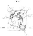
図12は、本実施例の洗濯乾燥機の循環風路の構成を示す模式図である。図中、循環空気をヒートポンプ装置1を経由して回転ドラム103へ戻すE循環風路75を実線で示し、循環空気をヒートポンプ装置1をバイパスして回転ドラム103へ戻すF循環風路76を破線で示している。一点鎖線で囲われた枠内は、洗濯乾燥機本体100の内部を模式的に示したもので、左側が洗濯乾燥機筺体の前面側に相当し、右側が背面側に相当する。
FIG. 12 is a schematic diagram showing the configuration of the circulation air path of the washing and drying machine of the present embodiment. In the figure, the E circulating air passage 75 for returning the circulating air to the
上述のように2系統の循環風路を備えた構成とすることで、ヒートポンプ装置1を用いた乾燥運転に加えて、ヒートポンプ装置1をバイパスしたF循環風路76を用いた空気の循環運転が可能となる。
As described above, with the configuration including the two circulation air passages, in addition to the drying operation using the
運転パターンの一例として、乾燥運転開始前に、所定の時間F循環風路76を用いた循環運転を行うことを想定する。F循環風路76のみを用いる循環運転では、ヒートポンプ装置1を経由するE循環風路75と比較して風路の圧力損失が小さいため、風量を上げた運転が可能となる。風量を上げて循環運転を継続していくと、送風ファンモータ81の発熱が空気に伝わり、循環空気温度は徐々に上昇していく傾向にある。
As an example of the operation pattern, it is assumed that the circulation operation using the F
脱水終了時にF循環風路76のみを用いた運転を行うことにより、脱水により回転ドラム103内面に張り付いた衣類200をほぐす効果や、衣類200の温度を上昇させる効果がある。前述の効果により、E循環風路75を用いた乾燥運転時に衣類200からの水分の蒸発が促進され、乾燥効率を向上させることが可能となる。このため、乾燥消費電力量の増加を抑えた省エネルギー化を図る効果と、高速、高風量の空気を衣類に吹き付けることによる乾燥運転時の高い仕上がり性を得る効果がある。
By performing the operation using only the F
また、図12においてE循環風路75、およびF循環風路76は独立した風路として示されているが、構造を限定するものではなく、回転ドラム103からリントフィルタ90までの風路や、送風ファン8から回転ドラム103までの風路を共通化した構成としてもよい。風路を共通化した場合には、別途風路の閉め切り手段(図示せず)及び開放手段(図示せず)が必要となるが、風路構成をコンパクトに出来る。
In addition, in FIG. 12, the E circulation air passage 75 and the F
また、上述のように循環空気を、ヒートポンプ装置1をバイパスして送風ファン8に吸引される空気流と、ヒートポンプ装置1を経由して除湿及び加熱された後に送風ファン8に吸引される2つの空気流に分岐するような構成とした場合、二つの風路のうち、ヒートポンプ装置1を経由する風路の方が熱交換器(蒸発器4、凝縮器3)を通過するために、空気の通風抵抗が大となる。このため、循環空気は、ヒートポンプ装置1をバイパスする流路に多く流れることになる。
Further, as described above, the circulating air is bypassed by the
乾燥運転開始時には、ヒートポンプ装置1の立ち上がり特性が乾燥運転効率に影響を与えるため、圧縮機2の起動時は送風ファン8の風量を絞った運転をすることがある。上述のようにヒートポンプ装置1をバイパスする風路を設けることで、送風ファン8の運転状態を一定のままヒートポンプ装置1へ流れる風量を絞ることが可能となり、暖機運転と同様の効果を得ることが出来る。
At the start of the drying operation, the startup characteristic of the
このように、ヒートポンプ装置1の運転立ち上がりを早くすることにより、乾燥運転時間を最適に制御可能となり、乾燥運転時の消費電力量の増大を抑え、省エネルギー化を図る効果を得ることができる。
Thus, by making the operation start of the
また、ヒートポンプ装置1をバイパスして流れる風路構成にすると、循環空気に含まれたリントを、リントフィルタ90において効率良く捕集することが可能となる。従って、乾燥運転中にリントが大量に発生する工程で排気ダクト73に配置した冷却部17を利用することで、循環空気中のリントは、リントフィルタ90に流入する前に冷却部17上で捕集される。
In addition, when the air path configuration bypassing the
このような構成にすることで、リントフィルタ90が閉塞して通風抵抗が増加するまでの時間を長くすることが可能となり、乾燥運転中のファン動力の低減につながるため、乾燥時の省エネルギー化に効果がある。
By adopting such a configuration, it becomes possible to lengthen the time until the
また、ユーザの選択により、衣類200を短時間で乾燥させるコースを選ぶことが可能である。上記のコースでは、循環空気の回転ドラム103への吹込み温度を高く設定するために圧縮機の回転速度を増加させることや、脱水運転中にヒートポンプ装置1を暖機運転することが行われる。このような運転を行うと、圧縮機2の入力が増大する可能性があるが、回転ドラム103とヒートポンプ装置1を循環している循環空気の温湿度の変化から、衣類200の乾燥状態を推定することにより、乾燥運転時間を決定し、消費電力量の大幅な増大や、衣類200への過大な加熱を抑制することが可能となる。上述の構成により、省エネルギー化を図った乾燥運転を実現することができる。
Further, it is possible to select a course for drying the
また、脱水運転時には、衣類200から脱水された水分と回転ドラム103内の高湿の空気は排水ホース110から洗濯乾燥機20外部へ排出される。この時ヒートポンプ装置1を運転することにより、高湿の空気を冷却部17上で結露させて排出することが可能となる。
Further, during the dehydration operation, the moisture dehydrated from the
上述のような運転より、乾燥運転時の循環空気から効率よく水分を除去することが可能となり、乾燥運転時の時間短縮と消費電力量の大幅な増大を抑える効果を得ることができる。 From the above operation, moisture can be efficiently removed from the circulating air during the drying operation, and the effect of shortening the time during the drying operation and suppressing a significant increase in power consumption can be obtained.
また、循環空気の吹出口14を外槽前面カバー102に設け、循環空気の排出口15を、外槽101の背面部のいずれも回転ドラム103の回転軸よりも上方に設け、さらに排出口15の位置を、吹出口14の位置に対して回転ドラム103の回転中心軸に近い位置とする構成とする。
In addition, a circulating
このような構成とすれば、吹出口14から回転ドラム103内へ流れる空気流は、洗濯乾燥機20の前面から見て左斜め下方に向かって吹出される。循環空気の排出口15をその対角となる背面側に設けることで、吹き込まれた空気が排出口15へショートカットして流れることは抑制される。上記の構成により、回転ドラム103内の衣類200に高速高圧空気を吹き付けることにより、乾燥時にしわの少ない、高い乾燥仕上り性を実現することが可能となる。また、衣類200と乾燥空気が直接当たりやすくなると、衣類200からの水分の蒸発が促進される。排出口15からは衣類200から蒸発した水分を含んだ空気をヒートポンプ装置1に導入しやすくなるため、乾燥効率を向上させた運転が可能となる。したがって、乾燥運転時の消費電力量を抑えて省エネルギー化を図れる。
With such a configuration, the airflow flowing from the
上記各実施例においては、適用装置として、ドラム式洗濯乾燥機を例として説明したが、乾燥方式にヒートポンプ装置を用いた縦型の洗濯乾燥機についても適用可能である。また、乾燥機能のみを有する乾燥機についても適用可能である。 In each of the above-described embodiments, the drum-type washing / drying machine has been described as an example of the application apparatus. It can also be applied to a dryer having only a drying function.
1…ヒートポンプ装置、
2…圧縮機、
3…凝縮器、
4…蒸発器、
4a…蒸発器、4b…蒸発器、
5…減圧装置、
5a…減圧装置、5b…減圧装置、
6…冷媒配管、
70…入口側流路
71…出口側流路、
72…送風ファン入口ダクト、
73…排気ダクト、
74…吹出しダクト、
75…E循環風路
76…F循環風路
8…送風ファン、
81…送風ファンモータ、
90…リントフィルタ、
91…フィルタケース、
10…風路の分岐部
11…伝熱管、
12…フィン、
13…制御装置、
14…吹出口、
15…排出口、
16…冷媒回路
17…冷却部
18…ケーシング
18a…排水部
20…洗濯乾燥機、
30…四方弁
100…洗濯乾燥機筺体、
101…外槽、
102…外槽前面カバー、
103…回転ドラム
104…サスペンション、
105…ベース、
106…開口部、
107…駆動モータ、
108…洗剤投入手段、
109…排水弁、
110…排水ホース、
111…ドア、
112…給水ユニット、
200…衣類、
T1、T2、T3…温度センサ
V1、V2…バルブ
1 ... heat pump device,
2 ... Compressor,
3 ... Condenser,
4 ... Evaporator,
4a ... evaporator, 4b ... evaporator,
5 ... decompression device,
5a ... decompression device, 5b ... decompression device,
6 ... refrigerant piping,
70: Inlet side channel 71: Outlet side channel,
72 ... Blower inlet duct,
73 ... exhaust duct,
74 ... Blowout duct,
75 ... E
81 ... Blower fan motor,
90 ... Lint filter,
91 ... Filter case,
10 ... Branch part of the air passage 11 ... Heat transfer tube,
12 ... Fins,
13 ... Control device,
14 ... Blowout outlet,
15 ... discharge port,
16 ...
30 ... Four-
101 ... Outer tank,
102 ... outer tank front cover,
103 ...
105 ... Base,
106 ... opening,
107: Drive motor,
108: Detergent charging means,
109 ... Drain valve,
110 ... Drain hose,
111 ... door,
112 ... water supply unit,
200 ... clothes,
T1, T2, T3 ... Temperature sensors V1, V2 ... Valves
Claims (5)
前記ヒートポンプ装置は、圧縮機と、冷媒の熱を空気に放熱する凝縮器と、減圧手段と、空気から吸熱する蒸発器と、を順次接続した冷媒回路で構成され、
前記蒸発器の上流に乾燥運転時の循環空気の露点温度よりも低い温度となる冷却部を設けたことを特徴とする洗濯乾燥機。 In a washing and drying machine provided with a rotating drum, an outer tub enclosing the rotating drum, a heat pump device, a filter, a blower fan, and a circulation air passage connecting them,
The heat pump device is composed of a refrigerant circuit in which a compressor, a condenser that radiates heat of the refrigerant to the air, a decompression unit, and an evaporator that absorbs heat from the air are sequentially connected.
A washing and drying machine, wherein a cooling unit having a temperature lower than a dew point temperature of circulating air during a drying operation is provided upstream of the evaporator.
前記冷却部は、前記外槽から前記フィルタに至る経路と前記フィルタから前記蒸発器へ至る経路の両方あるいは一方に配置されたことを特徴とする洗濯乾燥機。 In the washing and drying machine according to claim 1,
The washing / drying machine according to claim 1, wherein the cooling unit is disposed in one or both of a path from the outer tub to the filter and a path from the filter to the evaporator.
前記冷却部の表面温度が前記蒸発器の表面温度よりも低くなることを特徴とする洗濯乾燥機。 In the washer / dryer according to claim 1,
The washing / drying machine, wherein a surface temperature of the cooling unit is lower than a surface temperature of the evaporator.
前記ヒートポンプ装置は、前記圧縮機と複数の熱交換器と、前記冷却部と、複数の減圧手段と複数のバルブを備え、冷却部と前記熱交換器を切り替え可能な冷媒回路を構成したことを特徴とする洗濯乾燥機。 In the washing and drying machine according to claim 1 to 3,
The heat pump device includes the compressor, a plurality of heat exchangers, the cooling unit, a plurality of decompression means, and a plurality of valves, and constitutes a refrigerant circuit capable of switching between the cooling unit and the heat exchanger. Features a washing dryer.
前記冷却部は、結露水が重力で流下可能な状態で配置したことを特徴とする洗濯乾燥機。 In the washing and drying machine according to claim 1 to 4,
The washing / drying machine is characterized in that the cooling unit is arranged in a state where condensed water can flow down due to gravity.
Priority Applications (1)
| Application Number | Priority Date | Filing Date | Title |
|---|---|---|---|
| JP2017169103A JP6321870B2 (en) | 2017-09-04 | 2017-09-04 | Refrigeration cycle equipment |
Applications Claiming Priority (1)
| Application Number | Priority Date | Filing Date | Title |
|---|---|---|---|
| JP2017169103A JP6321870B2 (en) | 2017-09-04 | 2017-09-04 | Refrigeration cycle equipment |
Related Parent Applications (1)
| Application Number | Title | Priority Date | Filing Date |
|---|---|---|---|
| JP2015090986A Division JP6518498B2 (en) | 2015-04-28 | 2015-04-28 | Washing and drying machine |
Related Child Applications (1)
| Application Number | Title | Priority Date | Filing Date |
|---|---|---|---|
| JP2018071838A Division JP2018102992A (en) | 2018-04-03 | 2018-04-03 | Refrigeration cycle equipment |
Publications (3)
| Publication Number | Publication Date |
|---|---|
| JP2017205651A true JP2017205651A (en) | 2017-11-24 |
| JP2017205651A5 JP2017205651A5 (en) | 2018-01-11 |
| JP6321870B2 JP6321870B2 (en) | 2018-05-09 |
Family
ID=60414557
Family Applications (1)
| Application Number | Title | Priority Date | Filing Date |
|---|---|---|---|
| JP2017169103A Active JP6321870B2 (en) | 2017-09-04 | 2017-09-04 | Refrigeration cycle equipment |
Country Status (1)
| Country | Link |
|---|---|
| JP (1) | JP6321870B2 (en) |
Families Citing this family (1)
| Publication number | Priority date | Publication date | Assignee | Title |
|---|---|---|---|---|
| JP2018102992A (en) * | 2018-04-03 | 2018-07-05 | 日立ジョンソンコントロールズ空調株式会社 | Refrigeration cycle equipment |
Citations (9)
| Publication number | Priority date | Publication date | Assignee | Title |
|---|---|---|---|---|
| JP2007531552A (en) * | 2003-09-29 | 2007-11-08 | セルフ プロペルド リサーチ アンド デヴェロプメント スペシャリスツ、エルエルシー | Heat pump clothes dryer |
| JP2009235338A (en) * | 2008-03-28 | 2009-10-15 | Mitsubishi Electric Corp | Coating composition, heat exchanger, air conditioner |
| WO2010027001A1 (en) * | 2008-09-04 | 2010-03-11 | 富士フイルム株式会社 | Method for producing hydrophilic member and hydrophilic member |
| JP2011115432A (en) * | 2009-12-04 | 2011-06-16 | Panasonic Corp | Clothes dryer |
| US20110277334A1 (en) * | 2010-04-28 | 2011-11-17 | Lee Yongju | Cloth treating apparatus |
| US20130008049A1 (en) * | 2011-07-07 | 2013-01-10 | General Electric Company | Device and method for heat pump based clothes dryer |
| JP2013081640A (en) * | 2011-10-11 | 2013-05-09 | Panasonic Corp | Clothes dryer |
| JP2014008485A (en) * | 2012-07-02 | 2014-01-20 | Tosei Corp | Liquid filter unit, drier and air conditioner |
| JP2014087549A (en) * | 2012-10-31 | 2014-05-15 | Toshiba Corp | Clothes dryer |
-
2017
- 2017-09-04 JP JP2017169103A patent/JP6321870B2/en active Active
Patent Citations (9)
| Publication number | Priority date | Publication date | Assignee | Title |
|---|---|---|---|---|
| JP2007531552A (en) * | 2003-09-29 | 2007-11-08 | セルフ プロペルド リサーチ アンド デヴェロプメント スペシャリスツ、エルエルシー | Heat pump clothes dryer |
| JP2009235338A (en) * | 2008-03-28 | 2009-10-15 | Mitsubishi Electric Corp | Coating composition, heat exchanger, air conditioner |
| WO2010027001A1 (en) * | 2008-09-04 | 2010-03-11 | 富士フイルム株式会社 | Method for producing hydrophilic member and hydrophilic member |
| JP2011115432A (en) * | 2009-12-04 | 2011-06-16 | Panasonic Corp | Clothes dryer |
| US20110277334A1 (en) * | 2010-04-28 | 2011-11-17 | Lee Yongju | Cloth treating apparatus |
| US20130008049A1 (en) * | 2011-07-07 | 2013-01-10 | General Electric Company | Device and method for heat pump based clothes dryer |
| JP2013081640A (en) * | 2011-10-11 | 2013-05-09 | Panasonic Corp | Clothes dryer |
| JP2014008485A (en) * | 2012-07-02 | 2014-01-20 | Tosei Corp | Liquid filter unit, drier and air conditioner |
| JP2014087549A (en) * | 2012-10-31 | 2014-05-15 | Toshiba Corp | Clothes dryer |
Also Published As
| Publication number | Publication date |
|---|---|
| JP6321870B2 (en) | 2018-05-09 |
Similar Documents
| Publication | Publication Date | Title |
|---|---|---|
| JP2018102992A (en) | Refrigeration cycle equipment | |
| CN103774402B (en) | Washing machine | |
| US9212450B2 (en) | Condensation dryer comprising a heat pump and method for operating the same | |
| US8490437B2 (en) | Drum type washing-drying machine | |
| CN106968079B (en) | Washer-dryer with cooling water circuit | |
| EP1961853A1 (en) | Clothes dryer | |
| US20050204755A1 (en) | Drying apparatus | |
| US9146056B2 (en) | Laundry treating apparatus having expansion valve which is variable according to the driving mode | |
| JP2007175528A (en) | Washing and drying machine | |
| JP2008048810A (en) | Clothes dryer | |
| JP2008067742A (en) | Clothes dryer | |
| WO2018123845A1 (en) | Clothes drying machine | |
| JP2009195364A (en) | Clothes dryer | |
| JP5121659B2 (en) | Washing and drying machine | |
| JP2006087484A (en) | Washing/drying machine | |
| JP2011087623A (en) | Clothes dryer | |
| JP2007143712A (en) | Washing/drying machine | |
| JP2009195362A (en) | Clothes dryer | |
| CN105189850B (en) | Drying machine | |
| JP6321870B2 (en) | Refrigeration cycle equipment | |
| JP6518498B2 (en) | Washing and drying machine | |
| JP2004089413A (en) | Clothes dryer | |
| JP2016123770A (en) | Washing and drying machine | |
| JP2007300945A (en) | Clothes drier | |
| JP6092004B2 (en) | Clothes dryer |
Legal Events
| Date | Code | Title | Description |
|---|---|---|---|
| A521 | Request for written amendment filed |
Free format text: JAPANESE INTERMEDIATE CODE: A523 Effective date: 20170906 |
|
| A711 | Notification of change in applicant |
Free format text: JAPANESE INTERMEDIATE CODE: A711 Effective date: 20171006 |
|
| RD02 | Notification of acceptance of power of attorney |
Free format text: JAPANESE INTERMEDIATE CODE: A7422 Effective date: 20171006 |
|
| A521 | Request for written amendment filed |
Free format text: JAPANESE INTERMEDIATE CODE: A821 Effective date: 20171006 |
|
| A521 | Request for written amendment filed |
Free format text: JAPANESE INTERMEDIATE CODE: A523 Effective date: 20171108 |
|
| A621 | Written request for application examination |
Free format text: JAPANESE INTERMEDIATE CODE: A621 Effective date: 20171108 |
|
| A871 | Explanation of circumstances concerning accelerated examination |
Free format text: JAPANESE INTERMEDIATE CODE: A871 Effective date: 20171108 |
|
| A975 | Report on accelerated examination |
Free format text: JAPANESE INTERMEDIATE CODE: A971005 Effective date: 20171205 |
|
| A131 | Notification of reasons for refusal |
Free format text: JAPANESE INTERMEDIATE CODE: A131 Effective date: 20171212 |
|
| A521 | Request for written amendment filed |
Free format text: JAPANESE INTERMEDIATE CODE: A523 Effective date: 20180213 |
|
| TRDD | Decision of grant or rejection written | ||
| A01 | Written decision to grant a patent or to grant a registration (utility model) |
Free format text: JAPANESE INTERMEDIATE CODE: A01 Effective date: 20180306 |
|
| A61 | First payment of annual fees (during grant procedure) |
Free format text: JAPANESE INTERMEDIATE CODE: A61 Effective date: 20180405 |
|
| R150 | Certificate of patent or registration of utility model |
Ref document number: 6321870 Country of ref document: JP Free format text: JAPANESE INTERMEDIATE CODE: R150 |
|
| R250 | Receipt of annual fees |
Free format text: JAPANESE INTERMEDIATE CODE: R250 |
|
| R250 | Receipt of annual fees |
Free format text: JAPANESE INTERMEDIATE CODE: R250 |
|
| R250 | Receipt of annual fees |
Free format text: JAPANESE INTERMEDIATE CODE: R250 |