EP2527520A1 - Articles treatment apparatus having heat pump system with safety element - Google Patents
Articles treatment apparatus having heat pump system with safety element Download PDFInfo
- Publication number
- EP2527520A1 EP2527520A1 EP11167563A EP11167563A EP2527520A1 EP 2527520 A1 EP2527520 A1 EP 2527520A1 EP 11167563 A EP11167563 A EP 11167563A EP 11167563 A EP11167563 A EP 11167563A EP 2527520 A1 EP2527520 A1 EP 2527520A1
- Authority
- EP
- European Patent Office
- Prior art keywords
- refrigerant
- heat pump
- pressure
- pump system
- loop
- Prior art date
- Legal status (The legal status is an assumption and is not a legal conclusion. Google has not performed a legal analysis and makes no representation as to the accuracy of the status listed.)
- Granted
Links
Images


Classifications
-
- D—TEXTILES; PAPER
- D06—TREATMENT OF TEXTILES OR THE LIKE; LAUNDERING; FLEXIBLE MATERIALS NOT OTHERWISE PROVIDED FOR
- D06F—LAUNDERING, DRYING, IRONING, PRESSING OR FOLDING TEXTILE ARTICLES
- D06F58/00—Domestic laundry dryers
- D06F58/20—General details of domestic laundry dryers
- D06F58/206—Heat pump arrangements
Definitions
- the invention relates to an articles treatment apparatus, in particular to a laundry treatment apparatus, a dryer, a washing machine or a washing machine having drying function, the apparatus comprising a heat pump system.
- the heat pump system is operating with the refrigerant being cycled in a totally supercritical state or a transcritical state.
- EP 2 060 671 B 1 suggests a tumble dryer having a heat pump system in which the refrigerant is cycled through the refrigerant loop in the gaseous state.
- the tumble dryer of WO 2008/105232 A1 has a heat pump system using CO 2 as refrigerant.
- a CO 2 leak detector is provided which monitors presence of abnormal CO 2 levels in the process air, which might unintentionally leak out of the CO 2 refrigerant loop of the heat pump system.
- CO 2 is detected, the closed process air cycle is opened by sucking ambient air through the drum and exhausting process air between the gas cooler and the gas heater of the heat pump system.
- WO 2008/105233 A1 provides a similar tumble dryer in which upon detecting a leak the loading door for loading laundry into the drum is safety locked.
- a method of operating an articles treatment apparatus having a heat pump system with a refrigerant loop is provided.
- the articles treatment apparatus may be a washing machine, a washing machine having drying function, a tumble dryer, a cabinet dryer or a dishwasher.
- the heat pump system comprises a refrigerant loop in which the refrigerant is circulated by the pumping activity of a compressor.
- the high pressure refrigerant that was pumped by the compressor is flowing into a second heat exchanger for cooling the refrigerant, which means that the heat of the high pressure refrigerant is transferred from the refrigerant to another medium.
- the medium is the processing air for drying the laundry.
- the heat is transferred to the washing liquor or liquid.
- the refrigerant cooled in the second heat exchanger is leaving the second heat exchanger and is flowing to a refrigerant expansion device in which the pressure of the refrigerant is significantly reduced.
- the expanded and low-pressure refrigerant that has passed the refrigerant expansion device flows into a first heat exchanger for heating/evaporating the refrigerant.
- the heating of the refrigerant is made by transferring heat from a medium surrounding or flowing through the first heat exchanger to the refrigerant.
- the medium transferring heat to the refrigerant in the first heat exchanger is the processing air.
- the processing air is also the medium that receives heat in the second heat exchanger.
- the medium for heating the refrigerant in the first heat exchanger is for example ambient air that is flown from outside through the first heat exchanger and then the cold ambient air is exhausted to the outside environment of the articles treatment apparatus.
- the condition of the refrigerant in the refrigerant loop is detected, preferably using a refrigerant condition detector providing a refrigerant condition signal and/or a switching signal in dependency of the refrigerant condition.
- the operation mode of the heat pump system is modified.
- Modification of the operation mode of the heat pump system also means a modification of the operation mode of the articles treatment apparatus. Modification of the operation mode of the articles treatment apparatus does not necessarily result in a modification that is observable by the user of the articles treatment apparatus or result in a significant change of the running articles treatment program.
- the running articles treatment program is modified, the user is informed of a service requirement and/or the articles treatment apparatus is set to stand-by or permanent operation stop.
- the pressure of the refrigerant in the refrigerant loop is reduced.
- the refrigerant pressure is detected directly (detecting the refrigerant pressure by a pressure detector) and/or indirectly (detecting the refrigerant temperature and/or an operation condition of the compressor) in a predefined section of the refrigerant loop.
- the refrigerant pressure is expected to be the highest, namely in the section between the outlet or outlet side of the compressor and the inlet or inlet side of the second heat exchanger.
- the refrigerant pressure to be reduced by modifying the operation mode of the heat pump system is in the high pressure side or branch of the refrigerant loop, more specifically in the section between the outlet or outlet side of the compressor and the inlet or inlet side of the second heat exchanger.
- the operation mode of the heat pump system is modified when the refrigerant condition indicates an abnormal state of operation or the approach thereto. In the abnormal state the refrigerant condition and/or the temporal gradient of the refrigerant condition is outside the condition bandwidth (temperature and/or pressure) in which the refrigerant exists during normal operation of the articles treatment apparatus.
- the abnormal state is the overpressure state of the refrigerant that is detected as mentioned above.
- the overpressure state of the refrigerant is detected using pressure and/or temperature detection of the refrigerant - preferably in the high pressure side of the heat pump system.
- the overpressure state of the heat pump system is present when a predefined overpressure level of the refrigerant is reached or exceeded in the high pressure branch of the refrigerant loop.
- the refrigerant used in the refrigerant loop is CO 2 .
- the heat pump system is operated such that the refrigerant is above the critical pressure (beyond the critical point such that the refrigerant is in the fluid or supercritical phase) at least in the high pressure side or branch of the refrigerant loop.
- the medium that is exchanging heat at or in the first and second heat exchanger is not necessarily used for articles treatment.
- the medium is air or water that is heated/cooled by the medium.
- the home appliance is a cooling apparatus like a refrigerator, a freezer or an air conditioner.
- the home appliance in its application for treating articles is for example a laundry treatment apparatus like a washing machine, a dryer-washer or a dryer.
- the articles treating home appliance is a dishwasher.
- the medium is air and the first heat exchanger for cooling the medium is at the same time adapted to dehumidify the air flown through or over the first heat exchanger.
- a refrigerant condition detector is configured to detect an abnormal state or condition of the refrigerant in the refrigerant loop.
- the abnormal state or condition is an overpressure state, in particular an overpressure state of the refrigerant in the section of the refrigerant loop which is located between the compressor outlet or outlet side and the inlet or inlet side of the refrigerant expansion device ("the high pressure branch" of the refrigerant loop).
- the safety unit is adapted to detect the refrigerant overpressure state in the section of the refrigerant loop between the compressor outlet or outlet side and the inlet or inlet side of the second heat exchanger.
- an overpressure state also means a temperature of the refrigerant in a predefined range
- detecting the temperature is an equivalent means for indirectly detecting an overpressure state, i.e. an abnormal state.
- the refrigerant release detector is used to detect release of refrigerant at a predefined position, for example through an overpressure valve which is part of the heat pump system, and if under normal operation condition no refrigerant is released at this position, the refrigerant release detector may be alternatively or additionally used to detect the abnormal state.
- the abnormal state refrigerant condition detection using for example refrigerant temperature, refrigerant pressure and/or refrigerant release can be combined in any combination.
- a double check of conditions for determining the abnormal state can be used in that on the one hand the abnormal state is detected based on the pressure and on the other hand the occurrence of the abnormal state is double checked using the temperature.
- the operation mode of the heat pump system is modified.
- the modification can be made on a sub-controller level or can be made on a controlled level executed by a controller or controller sub-unit of the articles treatment apparatus or heat pump system.
- Modification of the operation mode of the heat pump system can be executed by one or any arbitrary combination of the following:
- the operation mode of the articles treatment apparatus as such can be modified.
- the article treatment apparatus can change from the user selected program to a security program in which the treatment process is finished, but e.g. with a reduced efficiency as compared to the previously selected program.
- the operation mode of the compressor is changed.
- the opening state of the refrigerant expansion valve and/or a pressure release valve is modified.
- the operation mode of an air blower is modified.
- the air blower may for example be a blower that is conveying the processing air or ambient air.
- the conveyance rate can be increased or maximized.
- the blower is an ambient air blower that sucks in ambient air from outside the articles treatment apparatus.
- the ambient air conveyed by the blower is used in the normal operation state or steady state to remove heat from the refrigerant loop.
- the ambient air is flown through or over the compressor and/or an auxiliary heat exchanger (auxiliary condenser).
- the modification of the operation mode of the articles treatment apparatus may be a switching off of the article treatment apparatus, setting it to a stand-by mode until the abnormal state is overcome (which for example may be detected via the state of the detector signal for the refrigerant condition detector), or the stand-by mode is activated for a predetermined time period.
- the operation mode of the articles treatment apparatus may be changed to a secured operation mode in which the heat pump system is operated under a predetermined maximum load. If for example the ambient condition or the ambient temperature is high and the heat pump system came to the abnormal state due to the high ambient temperature, then the secured operation mode may provide a slowed down process where the heat pump system may securely operate even under high ambient temperature condition.
- the predetermined maximum load (preferably the time-averaged maximum load) is for example up to 95%, 90%, 85% or 80% of the nominal operation power for the executed process.
- the compressor is operated with such reduced maximum or nominal power. This means for example an extended processing time as compared to the normal processing under moderate ambient conditions.
- the operation mode of the heat pump system in particular of individual components of the heat pump system, is modified in dependency of the signal state of the signal provided by the refrigerant release detector and/or in dependency of a signal provided by a refrigerant condition detector.
- the modification of the operation mode may include one or more of following:
- the operation mode of the articles treatment apparatus is changed for example in that the program that was executed before the abnormal state (here: the refrigerant release) occurred, e.g. is changed to a secured operation mode of the articles treatment apparatus.
- the maximum nominal power of the articles treatment apparatus or the heat pump system (in particular of the compressor) is reduced to below 95%, 90%, 85% or 80% of the nominal maximum power.
- the operation mode of the compressor is modified for example by reducing its pumping rate, reducing the on/off duty ratio when the compressor is intermittently operated, or the compressor is stopped for a predetermined period.
- the opening state of a refrigerant release device is modified, for example the opening cross section is opened in dependency of the signal strength of the signal from the refrigerant release detector and/or the refrigerant condition detector.
- the refrigerant release device is preferably fluidly connected to the refrigerant loop in a section between the outlet or outlet side of the compressor and the inlet or inlet side of the second heat exchanger (i.e. a section where the refrigerant expansion device is not connected).
- the opening state of the refrigerant expansion device is modified such that more refrigerant is expanded from the high pressure branch to the low pressure branch as would be the case if no refrigerant would be released.
- the operation mode of an air blower is modified. For example the conveyance power of the blower is increased or the blower is set to maximum blowing power.
- the air blower is for example a process air blower in a dryer , cabinet dryer or washing machine having dryer function or the blower is an ambient air blower that sucks ambient air into the articles treatment apparatus and exhausts the air to the outside of the apparatus again.
- the modified operation mode of the compressor may include one or more of the following, in particular any combination of the following:
- the power supply to the compressor can be interrupted for at least a period of time, the operation speed or pumping rate of the compressor can be reduced, for example for the rest of the running process or for a predefined period or time or until a returned to normal state (the current condition is for example indicated by one or more refrigerant condition detectors).
- the compressor can be set to a stand-by mode (which means a stand-by mode for the heat pump system in general) until the state of the detector signal or switch signal of the refrigerant condition detector has returned to normal state (abnormal state is overcome).
- the compressor is intermittently switched on or off or the off/on duty cycle of operation periods for the compressor is increased.
- Modification of the opening state of the pressure release valve may include one or more of the following or any combination thereof:
- the pressure release device e.g. valve
- the pressure release device is opened for a predefined period to release some refrigerant, preferably to release refrigerant from the high pressure branch of the refrigerant loop.
- the opening period of the pressure release device is adapted in dependency of the detector signal. If for example a moderate overpressure state (abnormal state) is indicated, the pressure release device may be opened for a short period, while, if a high overpressure state is indicated, the pressure release device is opened for an extended period. Alternatively the pressure release device is opened as long as the detector signal (including the switching state of the detector indicates the abnormal state of the refrigerant).
- Modification of the opening state of the refrigerant expansion device may be performed the same way as the pressure release device, wherein releasing refrigerant from the high pressure branch to the low pressure branch of the refrigerant loop is made by partially or fully opening the refrigerant expansion device, if it is a controllable or/and adjustable refrigerant expansion device, or a bypass valve bypassing the refrigerant expansion device is opened.
- the air blower upon detecting the abnormal state, the air blower can be activated, its flow rate can be increased in dependency of the detector signal or as long as the abnormal state is detected via the detector signal of a or the refrigerant condition detector.
- the air blower may be the blower for circulating the process air in a dryer or dryer cabinet or washing machine having dryer function, the blower can be an ambient air blower that is blowing the air to the second heat exchanger, the compressor and/or an auxiliary heat exchanger.
- the refrigerant expansion valve and/or the pressure release valve are opened.
- the refrigerant expansion valve and/or the pressure release valve are normally open valves (which open upon removing the power supply therefrom), the refrigerant can flow through the expansion valve and/or pressure release valve when the power supply thereto is cut off to reduce the refrigerant pressure, e.g. at the high pressure branch of the refrigerant loop.
- the pressure release from the high pressure branch of the refrigerant loop can be made by releasing refrigerant to the low pressure branch of the refrigerant loop, to a refrigerant reservoir unit that is connected to the refrigerant loop (but not part of the active refrigerant loop), and/or refrigerant may be released to the outside of the refrigerant loop, in particular to the ambient and/or inner environment of the articles treatment apparatus.
- the textiles treatment apparatus for returning from the abnormal state to the normal or steady state, is operated as follows:
- the refrigerant pressure is detected and in case of an overpressure state (which is detected for example using the pressure and/or temperature sensor and by evaluating it by the controller), moderate countermeasures are executed under the control of the controller to overcome the overpressure state (like reducing the pumping rate of the compressor or temporally stopping the compressor and/or further opening the expansion device).
- an overpressure state which is detected for example using the pressure and/or temperature sensor and by evaluating it by the controller
- moderate countermeasures are executed under the control of the controller to overcome the overpressure state (like reducing the pumping rate of the compressor or temporally stopping the compressor and/or further opening the expansion device).
- a more significant change in the operation mode of the articles treatment apparatus e.g. in its pump system
- the normal operation state is the operation state of the heat pump system after the warm-up period.
- the refrigerant in the high pressure and/or low pressure branches of the refrigerant loop has a reached a set value for the refrigerant temperature and/or pressure or is within a target range around the set value for the refrigerant temperature and/or pressure.
- the heat deposited by the compressor in the refrigerant loop is removed by a heat sink being in heat transfer connection with the refrigerant loop.
- a blower is provided which in the normal state or steady state blows ambient air over the compressor and/or over an auxiliary heat exchanger that is included in the refrigerant loop.
- the refrigerant condition detector provides a detector signal that may be used by other components and/or a control unit of the heat pump system or articles treatment apparatus to modify or change a state of the heat pump system as such or a component thereof.
- the refrigerant condition detector may operate as a switch, for example as a pressure switch that is switching at a predefined pressure level.
- the refrigerant condition detector provides a signal to a controller of the articles treatment apparatus or the controller of the heat pump system or a dedicated controller for monitoring the signal of the refrigerant condition detector, which evaluates or processes the detector signal and provides a decision on the presence or absence of an abnormal state.
- a state of a switch can be changed - either by the detector directly or via one of the previously mentioned controllers, and initiated by the switching state of the switch one or more components of the articles treatment apparatus and/or the heat pump system (e.g. the refrigerant expansion device, the compressor, a blower) are switched off or are opened (e.g. the expansion device).
- the evaluation or processing of the detector signal in the controller of the treatment apparatus, the heat pump system or the dedicated controller results in a change of the operation control process of one or more components of the articles treatment apparatus or heat pump system (change of operation of the component see below).
- the controller of the heat pump system or the articles treatment apparatus receives at the same time a switching signal from the refrigerant condition detector and/or detects a change in the state of a component of the heat pump system using another sensor or detector. If for example the power supply to the compressor is switched off by the refrigerant pressure detector or by its dedicated sub-level controller or control electronics, then a signal from the detector supplied to the heat pump system controller or articles treatment apparatus controller may indicate non-operation of the compressor.
- the operation mode of the heat pump system is modified in dependency of the refrigerant condition indicated by the detector signal or switching signal of the refrigerant condition detector.
- the modification can be made on a sub-controller level or can be made on a controlled level executed by a controller or controller sub-unit of the articles treatment apparatus or heat pump system.
- a safety unit comprising or being a or the refrigerant condition detector is arranged at or in fluid connection with the refrigerant loop.
- the refrigerant condition detector is for example a refrigerant pressure detector, a refrigerant temperature detector and/or a refrigerant release detector.
- the pressure detector is preferably in fluid connection to the refrigerant loop so that a pressure at a predefined location of the refrigerant loop can be detected.
- the refrigerant temperature detector may be arranged in thermal contact with the piping system connecting the above mentioned components of the heat pump system, the temperature detector may be in fluid contact with the refrigerant in the refrigerant loop or may be arranged in thermal contact with the refrigerant that is guided through the first heat exchanger, the second heat exchanger, the refrigerant expansion device or the compressor.
- the refrigerant release detector may be a mechanically switched detector, a flow detector and/or a flow rate detector or any other detector detecting the release of refrigerant, for example the release of refrigerant through a valve or refrigerant release device that is normally not open.
- the safety unit (preferably being or comprising a refrigerant condition detector) comprises a safety circuit which receives the signal from the refrigerant condition detector and processes it. Processing can include to determine whether a predefined threshold has been reached or exceeded. Alternatively or additionally processing results for example in a proportional reaction in response to the strength, intensity and/or amplitude of the signal from the refrigerant condition detector and initiates a modification of the operation state of the articles treatment apparatus, the heat pump system and/or individual components of the heat pump system.
- a dedicated safety circuit (the sub-controller unit) may be an analog circuit, a digital circuit or a hybrid circuit. Additionally or alternatively the safety circuit is embedded in a controller of the articles treatment apparatus, for example in the main control unit of the articles treatment apparatus or a controller of the heat pump system.
- valve e.g. refrigerant expansion valve or pressure release valve
- 'valve' is generally an example for 'device' (e.g. refrigerant expansion device or pressure release device).
- the refrigerant release device is not the refrigerant expansion device and/or the refrigerant release device is provided in addition to the refrigerant expansion device and its function.
- overpressure level may relate to an absolute overpressure value, which means that it is the pressure of the refrigerant at the inlet of the refrigerant release device measured against the ambient or an absolute pressure level.
- overpressure level may relate to a pressure difference between the inlet and outlet of the refrigerant release device.
- the heat pump system is operating under a transcritical or totally supercritical thermodynamic cycling mode.
- the refrigerant in the high pressure side of the heat pump system is existing in the supercritical phase as soon as the heat pump system has reached the normal operation conditions (the steady-state).
- refrigerant CO 2 gas is used.
- the articles treatment apparatus further comprises a or the refrigerant release device which is in fluid connection to a high pressure side or branch of the refrigerant loop.
- the high pressure side or high pressure branch of the refrigerant loop is the section of the refrigerant loop between the outlet or outlet side of the compressor and the inlet or inlet side of the refrigerant expansion device.
- the fluid connection of the refrigerant release device is made between the outlet of the compressor and the inlet of the second heat exchanger.
- the refrigerant release device is adapted to release refrigerant from the refrigerant loop through an outlet of the release device.
- refrigerant release device pressure or refrigerant is removed from the high pressure branch.
- Release of refrigerant through the release device may be initiated preferably automatically and/or in a controlled manner.
- the release of the refrigerant is stopped by the release device automatically and/or in a controlled manner.
- the refrigerant release device operates under the control of a controller of the articles treatment apparatus and/or the heat pump system such that the refrigerant release device is a controlled device and can be opened and/or closed in a controlled manner.
- the refrigerant release device is an automatically opening (and preferably an automatically closing) release device that releases a refrigerant when reaching or exceeding a predefined pressure level of the refrigerant.
- the controllable release device may be a valve driven by a solenoid, a motor or another actuator which provides actuation of the valve to open (and preferably to close).
- the actuated opening can be implemented in an adjustable opening or a proportional opening control that means that the cross section of opening is adjustable to predefined degree, or the opening and closing is made in a binary manner (i.e. completely opening and closing the release cross section).
- an automatically opening pressure release device may be provided which cross section is opened proportionally to the overpressure applied at its inlet or which can be opened completely when the overpressure level has been achieved or exceeded.
- the refrigerant release device is an overpressure release device, in particular an overpressure release device having an elastic and/or spring-biased element for opening at or above a predefined overpressure level and preferably for closing the release device in a biased manner at or below the predefined overpressure level or at or below a second overpressure level.
- opening of the refrigerant release device is made at a first overpressure level and the release device is closed when undershooting the first overpressure level.
- the release device may open at a first overpressure level and may close at a second overpressure level which is for example lower than the first overpressure level (operation in a hysteresis mode).
- the opening and closing with or without hysteresis may be implemented in the controlled release device using a controller or control electronics, or may be implemented for the automatically operating release device.
- the automatically operating refrigerant release device may be driven by an elastic or spring-biased element which opens at or above a predefined overpressure level and closes if the predefined overpressure level or a second predefined overpressure level is undershot.
- the control of the controllable refrigerant release device may be implemented via a controller of the articles treatment apparatus and/or the heat pump system, by a dedicated control electronics that is dedicated to detect an overpressure or abnormal state of the refrigerant within the refrigerant loop and which reacts thereon to open the control release device.
- a pressure sensor may be connected to a switch which switching state is changed when at the predefined overpressure level or when exceeding and the switch signal is directly fed from the pressure sensor to the release device to change the opening state of the release device.
- a current switch connected to the pressure detector is switched and power is supplied to the actuator of the release device which opens under the actuation of the powered actuator.
- an analog pressure signal is fed to a dedicated pressure level monitor electronic which sends a power signal to the actuator of the release device upon detecting via the analog pressure signal that an overpressure level has been reached or exceeded.
- the overpressure or abnormal state of the heat pump system is monitored by the controller of the heat pump system which can evaluate the pressure signal of a pressure detector or the temperature signal of a temperature detector in a more complex manner to determine whether an overpressure or abnormal state has occurred and can then control the release device to open.
- the control under the heat pump system and/or articles treatment apparatus can be combined with a lower level operation of the release device (simple switching electronic or dedicated pressure monitoring electronic) to have a redundant structure for opening the refrigerant release device.
- the outlet of the refrigerant release device is connected to the low pressure branch of the refrigerant loop.
- the low pressure branch of the refrigerant loop is the section of the refrigerant loop between the outlet or outlet side of the refrigerant expansion device and the inlet or inlet side of the compressor.
- the outlet is connected to the section of the refrigerant loop between the outlet or outlet side of the first heat exchanger and the inlet or inlet side of the compressor.
- the refrigerant expansion device is bypassed by an overpressure bypass forming the refrigerant release device.
- refrigerant is released from the high pressure branch between the second heat exchanger and the expansion device to the low pressure branch between the outlet of the expansion device and the inlet of the first heat exchanger.
- the refrigerant expansion device itself is or is implementing the refrigerant release device or part thereof.
- the refrigerant expansion device is or is implementing an overpressure valve opening when reaching or exceeding a predefined overpressure level or is or is implementing a controllable valve that is (further) opened in case an abnormal state or overpressure state is detected.
- the outlet of the release device is connected to a container such that the refrigerant released through the release device is fed into the container, preferably to be stored in the container.
- Releasing the refrigerant into the container avoids a release of the refrigerant for example into the environment or to the outside of the refrigerant loop or heat pump system.
- the release of the refrigerant into the container removes a portion of the refrigerant from the refrigerant loop such that the overall amount of refrigerant in the loop and thus the overall pressure in the refrigerant loop is reduced which is convenient for easily removing the overpressure state.
- the refrigerant collected in the container can be re-fed into the refrigerant loop.
- the amount of refrigerant previously released from the refrigerant loop into the container during the abnormal or overpressure state is re-fed to the refrigerant loop and the original operation conditions can be re-established.
- re-feeding from the container to the refrigerant loop is made when the pressure in the container is higher than the refrigerant in the loop.
- the refrigerant may be re-fed to the refrigerant loop at any position in the refrigerant loop, but preferably the refrigerant is re-fed to the loop between the outlet or outlet side of the first heat exchanger and the inlet or inlet side of the compressor or between the outlet or outlet side of the compressor and the inlet of the second heat exchanger.
- the container refrigerant release device when the refrigerant is re-fed through the container refrigerant release device into the low pressure side or branch of the loop, the container refrigerant release device is automatically opened or opened in a controlled manner during an initial start phase of starting the heat pump system when the pressure in the low pressure branch of the loop is low. Thereby, most of the previously released refrigerant is recycled into the refrigerant loop.
- the container refrigerant release device is the refrigerant release device which is operated under the control of a controller (of the articles treatment apparatus or the heat pump system) and the control provides that the release device is operating as overpressure release device during an overpressure or abnormal state and is operated as a container refrigerant release device as soon as the overpressure state is overcome and a pressure drop between the container and a feeding point in the refrigerant loop is detected or is expected under the corresponding operation conditions of the heat pump system.
- a controller of the articles treatment apparatus or the heat pump system
- the container is connected via a first pressure release device to the high pressure branch of the refrigerant loop and is adapted to controllably or automatically release refrigerant in an abnormal or overpressure state
- a second pressure release device fluidly connects the container to the refrigerant loop for controllably or automatically releasing the refrigerant from the container to the refrigerant loop when there is pressure drop from the container to the feeding point in the refrigerant loop or when there is a convenient operation condition of the heat pump system for releasing the refrigerant from the container into the refrigerant loop.
- the refrigerant release device may be a no-return or single-path safety device that opens at a predetermined minimum pressure that is not closing again as soon as the predefined minimum pressure has been overshot.
- the release device is a single-occasion security device that results in a service requirement for the heat pump system.
- a no-return safety device is applied for a high predefined overpressure level which is higher than for example a first overpressure level where a non-destructive overpressure device is activated.
- the refrigerant release device is an automatic and self-closing release device that opens at a predetermined first pressure and closes at a predetermined second pressure, wherein the first and second pressures may be same or different (hysteresis).
- a refrigerant release detector is assigned to the refrigerant release device, preferably is coupled or in fluid connection with the release device.
- the refrigerant release detector is adapted to detect a state of the release device, preferably the state where the release device releases refrigerant.
- the release detector is for example an anemometer or a flow meter that detects refrigerant flow through the refrigerant release detector, or is a switch or other mechanical sensor that is detecting an opening of the release device. If for example the release device is a valve, the detector detects that the valve head is moved away from the valve seat.
- the release device and/or a refrigerant release detector provides a signal indicating the refrigerant release and/or indicating a signal in dependency of the refrigerant release flow rate and/or in dependency of the refrigerant amount released.
- This signal can be used for controlling components of the articles treatment or the heat pump system.
- the signal can be used and processed by a control unit of the articles treatment apparatus or heat pump system to modify the operation state of the heat pump system in dependency of the signal detected, in particular to take control activities for overcoming a overpressure or abnormal state, if this is detected on the basis of the signal from the pressure release device or the detector assigned thereto.
- a refrigerant release detector is adapted to provide a detector signal.
- a detector signal For example it provides an analog signal wherein the strength, intensity and/or amplitude of the signal depends on the amount or flow rate of the refrigerant being released.
- the detector signal is a digital signal or binary signal that indicates the two states 'release' or 'non-release' of refrigerant.
- the refrigerant release detector provides a switching signal wherein it is operating as a switch; for example for switching an operation state of a component in the articles treatment apparatus or the heat pump system.
- the pressure release from the high pressure branch of the refrigerant loop can be made by releasing refrigerant to the low pressure branch of the refrigerant loop, to a refrigerant reservoir unit that is connected to the refrigerant loop (but not part of the active refrigerant loop), and/or refrigerant may be released to the outside of the refrigerant loop, in particular to the ambient and/or inner environment of the articles treatment apparatus.
- Fig. 1 depicts in a schematic presentation a home appliance 2 which in this embodiment is a tumble dryer, especially a heat pump tumble dryer.
- the tumble dryer comprises a heat pump system 4, including: a first heat exchanger device 10 acting as gas heater, a second heat exchanger 12 acting as gas cooler, a compressor 14 and an expansion device 16.
- the heat pump system forms a refrigerant loop 6 through which - in normal operation - the refrigerant is circulated by the compressor 14 as indicated by arrow B.
- the expansion device 16 is a controllable valve that operates under the control of a control unit 30 to adapt the flow resistance for the refrigerant in dependency of operating states of the heat pump system.
- the expansion device 16 can be a capillary tube, a valve with fixed expansion cross-section, a throttle valve with variable cross section that automatically adapts the expansion cross-section in dependency of the refrigerant pressure (e.g. by elastic or spring biasing), a semiautomatic throttle valve in which the expansion cross-section is adapted in dependency of the temperature of the refrigerant (e.g. by actuation of a thermostat and/or where the temperature of the refrigerant is taken between the gas cooler and the gas heater, the gas heater and the compressor, or the compressor and the gas cooler), or the like.
- the process air flow within the home appliance 2 is guided through a compartment 18 of the home appliance 2, i.e. through a compartment 18 for receiving articles to be treated, e.g. a drum 18.
- the articles to be treated are textiles, laundry, clothes, shoes, dishes or the like. In the embodiment of Figs. 1 and 5 these are textiles, laundry, clothes.
- the process air flow is indicated by arrows A in Fig. 1 and is driven by a blower 19. Outside the compartment 18 the process air A is guided through an air channel 20.
- the air exiting the compartment 18 (here drum) through outlet 24 is filtered by fluff filters 22 arranged in or at the channel 20, flows through the first heat exchanger 10, through the second heat exchanger 12 and is guided back through an or a plurality of openings in the compartment into the compartment 18.
- fluff filters 22 arranged in or at the channel 20
- the first heat exchanger 10 transfers heat from the process air to the refrigerant.
- humidity from the process air condenses at the first heat exchanger 10 is collected there and the collected condensate is drained to a condensate collector 26.
- the process air cooled and dehumidified when passing the first heat exchanger passes then through the second heat exchanger 12 where heat is transferred from the refrigerant to the process air.
- the process air is sucked from exchanger 12 by the blower 19 and driven into the compartment where it heats up the articles and receives the humidity therefrom.
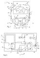
- Fig. 2 shows in schematic representation more details of the heat pump system 4.
- the heat pump system 4 is controlled by a heat pump controller 32 which in turn is part of the control unit 30 of the home appliance 2.
- the expansion device 16 is a controllable valve in which the flow resistance for the refrigerant can be controlled by an actuator (motor, solenoid or the like) via an adjustable flow cross-section.
- the heat pump controller 32 controls a power converter 15 which is supplying electrical power to the compressor 14 and is monitoring it.
- the power converter 15 is connected to a power source 15a like the home power grid and converts it into electrical signals convenient for the motor of the compressor.
- the power converter 15 includes a heat and over current sensor for motor protection. Control and monitoring signals are sent between the converter 15 and the controller 32.
- the heat pump system 4 or the refrigerant loop 6 can be considered as having two branches.
- the first branch is the high pressure side which is the loop part from the exit of the compressor 14 through exchanger 12 to the input of the expansion device 16 (more precisely to its reduced cross-section).
- the second branch is the low pressure side which is the loop part from the exit of the expansion device 16 (more precisely from its reduced cross-section) through the first heat exchanger 10 to the input of the compressor 14.
- the temperature of the refrigerant in the heat pump system 4 is increasing. With increasing refrigerant temperature the pressures in the two branches is increasing too, while a pressure difference is maintained between the high pressure branch and the low pressure branch. If for example CO 2 is used as refrigerant, the equilibrated pressure (high and low pressure branch have same pressure) under ambient conditions (temperature in range 15 to 35°C) of the refrigerant is in the range 40 to 65 bar. In steady-state operation the CO 2 pressure in the high pressure branch may go up to 120 bar and the overpressure value may be set to 140 bar.
- the flow cross-section of the expansion device 16 is reduced to accelerate the pressure and temperature build-up at the high pressure side of the heat pump system 4.
- the cross-section of expansion device 16 is enlarged under the control of heat pump controller 32.
- any other heat sink can be connected to the refrigerant loop 6.
- the steady state is then the state achieved after the warm-up period in which the power deposited by the compressor in the refrigerant loop (and the heat-connected processing air loop) is removed by the ambient air ventilated by the blower 17.
- the term 'steady state' means here the heat pump system 4 has achieved its nominal operation condition where the pressure and temperature of the refrigerant have achieved their set values. Normally the heat transfer efficiency of the heat pump system 4 is at its maximum in steady state.
- the 'steady state' also allows variations in refrigerant pressure and temperature within a given target range.
- heat can be removed from the refrigerant loop 6 (from the heat pump system 4) by a heat sink connected to the refrigerant loop 6 to take away heat from the refrigerant.
- a heat sink connected to the refrigerant loop 6 to take away heat from the refrigerant.
- an auxiliary heat exchanger (condenser; not shown) can be connected in the refrigerant loop 6 and heat is removed via an ambient air flow through or across the auxiliary heat exchanger for cooling the refrigerant. As described above heat removal is activated according to the conditions or requirements of the steady state.
- the set values for refrigerant temperature and pressure may be varied over time.
- the humidity of the articles to be dried changes over time such that normally the process air temperature of the process air flowing out of the laundry compartment 18 increases when the operation conditions of the heat pump system 4 are maintained.
- the temperature of the refrigerant in the gas cooler 12 can be reduced - and thus heat transfer to the process air that is to be blown into the laundry compartment 18.
- Reduction of refrigerant temperature in the gas cooler can for example be achieved by reducing the refrigerant pressure in the gas cooler (accompanied by reduction of pressure difference in the two branches).
- the 'steady state' is not necessarily invariant over time - rather it means that the current given set values (e.g. for refrigerant pressure and/or temperature) are achieved within the given target range.
- the change of 'steady state' over time can become necessary when the washing liquid is gradually heated up and the operation cycle of the refrigerant needs to be adjusted to improve efficiency of heat exchange in dependency of the changing washing liquid temperature.
- the heat pump system 4 of the present invention operates with refrigerant cycles that are in the transcritical range (transcritical thermodynamic cycle) as shown in Fig. 6a or in the supercritical range (totally supercritical cycle) as shown in Fig. 6b .
- transcritical cycle the compression (#1 > #2) transforms the refrigerant parameters so that they lie in the supercritical fluid range beyond the critical point CP.
- expansion (#3 > #4) the refrigerant parameters return to the liquid and vapor phase.
- the refrigerant parameters In the totally supercritical cycle the refrigerant parameters always lie in the supercritical fluid range beyond the critical point CP.
- CO 2 is used as refrigerant which has a critical point CP at the critical pressure of 73.8 bar and critical temperature of 31.0 °C.
- the pressure in the high pressure branch may be pumped with up to 120 bar by the compressor 14 in normal operation.
- the compressor 14 may charge the high pressure branch with 140 bar or more.
- a sudden and unintentional or uncontrolled refrigerant release at this pressure to the outside of the heat pump system 4 may have adverse effects to the home appliance (e.g. dryer 2 or washing machine 70) or may result in discomfort for the user.
- the home appliance e.g. dryer 2 or washing machine 70
- the following safety measures are implemented in the home appliance and by the operation method thereof:
- safety means and measures a) to f) can be provided in the heat pump system 4 individually or can be combined in any arbitrary combination. This means that while all elements are shown in Fig. 2 or Fig. 5 only one or some or all may be implemented in the heat pump system 4 to be used for the home appliance. Some combinations are preferred ones. For example a bypass arrangement 46 would not be used with an adjustable expansion device 16 (as the one shown), while it advantageously could be used, if the expansion device 16 is invariant like a capillary tube.
- a bypass arrangement 46 would not be used with an adjustable expansion device 16 (as the one shown), while it advantageously could be used, if the expansion device 16 is invariant like a capillary tube.
- a pressure sensor 34 is connected to the high pressure branch of the heat pump system 4.
- a temperature sensor 44 is in thermal contact with the refrigerant at the high pressure branch. As normally the pressure in the system 4 increases with temperature, the temperature is an indirect indication for the pressure in the system - at least under defined operation conditions of system 4.
- the pressure sensor 34 and/or temperature sensor 44 are connected in the section of the high pressure branch which is between the outlet or outlet side of the compressor 14 and the inlet or inlet side of the second heat exchanger 12.
- the detection of overpressure and/or over-temperature can also be denoted as excess temperature
- excess temperature is more reliable as compared to the detection at a downstream section of the high pressure branch where a temperature or pressure drop within the loop may happen, in particular a drop within the gas cooler 12.
- the signal(s) from sensor 34 and/or 44 is fed to the heat pump controller 32.
- the signal(s) are processed to detect the abnormal state.
- the signals are also processed in the controller 32 to monitor the normal state and/or warm-up phase conditions or other less safety-relevant conditions of the heat pump system 4.
- a less safety-relevant condition exists for example, if refrigerant pressure and/or temperature are below a minimum pressure and/or temperature value before starting the heat pump system 4, during its warm-up phase or during the steady state.
- the insufficiency value(s) indicate for example insufficient refrigerant for properly operating system 4.
- the heat pump controller 32 controls the expansion device 16 (in case of a controllable, adjustable expansion device like the controllable valve depicted as 16) to open partially or fully.
- the expansion device 16 By opening the expansion device 16 partially or fully, flow resistance is reduced (e.g. by opening the restricting cross-section) and the pressure drop from the high pressure to the low pressure branch is reduced.
- normal operation mode e.g. steady state operation
- Other control routines for operating the home appliance, in particular the heat pump system 4, after detection of the abnormal state are described below.
- Resuming normal operation mode when option a) is implemented normally includes partially or further closing the adjustable expansion device 16 to provide higher flow resistance again (e.g. to a value or degree as it was before detection of the abnormal state.
- a bypass arrangement 46 is provided through which refrigerant flows after opening the bypass line upon detecting an abnormal state.
- the bypass arrangement comprises a controllable valve that is opened under the control of the heat pump controller 32.
- the bypass arrangement 46 is for example provided, if the expansion device 16 has a fixed flow resistance, as for example a capillary tube. Or if even under the fully opened state the refrigerant flow through the expansion device is too low under the abnormal condition.
- a controllable and adjustable expansion device 16 may be combined with the bypass arrangement 46 and both are opened by the heat pump controller 32 when the abnormal state is detected. Or valve 16 is opened at a first excess level of the refrigerant overpressure and/or temperature and the valve in the bypass arrangement 46 is opened at a higher second excess level of the refrigerant overpressure and/or temperature.
- the expansion device 16 may be a controlled valve that may be controlled in a proportional way, i.e. the higher the pressure above the overpressure set value (as detected e.g. by sensor 34), the more the cross-section of the valve is opened. In this way a minimum equilibration between the high and low pressure branch is achieved in dependency of the severity of the overpressure state.
- the overpressure value is undershoot, i.e. the normal operation condition is re-established, pressure equilibration is stopped by further closing expansion device 16, resulting in a minimized loss of the operation efficiency of the heat pump system.
- a pressure sensor 34a is provided for detecting an overpressure state of the refrigerant.
- the pressure sensor 34a includes a pressure switch 34b which directly or via a relay 34c switches off the power supply 15a providing power to the power converter 15.
- the relay feeds a status signal to the converter 15 which upon a change in the state of the status signal (i.e. the overpressure state is indicated) sets the compressor 14 into a standby (off-) state or reduces its compression capacity, e.g. by lowering the rotation speed of the compressor.
- the abnormal state is detected by pressure sensor 34 and/or temperature sensor 44.
- the heat pump controller 32 evaluates the signal(s) from sensor 34 and/or 44 and in case of an excess temperature/or pressure of the refrigerant, the controller 32 controls compressor 14 by switching it off or by reducing its pumping rate. For example by reducing the rotational speed of the compressor.
- temporally switching off the compressor or reducing its pumping rate may also be used during the normal operation modes (warm-up phase, steady state) so as to keep set values for temperature and/or pressure in the given target range around the set value(s).
- Switching off of the compressor can be achieved by switching off the compressor only, by switching off the heat pump system 4 as a whole, or even by switching off the home appliance 2, 70 as whole.
- the start of the home appliance, the heat pump system 4, or the compressor 14 may be delayed by a minimum shut-down time which is sufficient that safe operation conditions for restarting the system are re-established.
- the minimum shut-down period is for example such that by heat dissipation or heat and/or pressure equilibration within the heat pump system conditions for a moderate operation cycle are established.
- the compressor may be restarted or normal pump rate may be resumed when the detection and evaluation of temperature and/or pressure of the refrigerant (by controller 32) results in reestablishment of normal operation conditions.
- Relief valve 36 provides a fluid connection between the high pressure branch and the low pressure branch of the refrigerant loop 6. In particular it provides a fluid connection (when opened) between the outlet and inlet of compressor 14.
- the relief valve 36 is operating automatically which means that it opens when an overpressure level is achieved or exceeded.
- valve 36 is an elastically or spring-biased one-way overpressure valve which opens when the excess pressure is achieved or exceeded and closes when the overpressure value is undershoot.
- the relief valve 36 is a controlled valve which opens and closes under the control of the heat pump controller 32. Opening and closing operation of such a controllable valve is then controlled by the controller 32 in response to detecting the abnormal state or detecting the return to the normal state as described before for option a).
- a release sensor 38 is assigned to the valve 36 to detect whether the valve 36 has been opened or is opened.
- the abnormal state is detected, i.e. here the overpressure state in the high pressure branch of the heat pump system 4 is detected.
- the pressure sensor 34 and/or the temperature sensor 44 are not required and can be omitted, or the signal (as) of sensor 34 and/or 44 is not required for detecting the abnormal state via evaluating the signal(s) by controller 32.
- valve 36 When valve 36 opens, the refrigerant flows from the high pressure to the low pressure branch and the abnormal state should be overcome after a while by pressure release from the high pressure branch.
- the controller 32 may take additional actions to overcome the abnormal state, for example by executing steps according to one or more of the other options a), b) or e).
- the controller 32 initiates the following control actions.
- the unidirectional exhaust valve 40 is connected to the high pressure branch of the refrigerant loop 6.
- the valve 40 is connected between the outlet or outlet side of the compressor and the inlet or inlet side of gas cooler 12, more preferably it is connected close to the compressor 14.
- valve 40 is an automatic overpressure release valve which for example has an elastic or spring-biased element that prevents refrigerant escape up to a set level of overpressure and which releases the refrigerant in case the overpressure level is achieved or exceeded.
- the overpressure release valve automatically closes when the overpressure level is undershooting.
- the exhaust valve 40 has an exhaust port or has an exhaust pipe with an exhaust port.
- the exhaust port is arranged such that in case of refrigerant release the refrigerant is set free at a location where neither the home appliance, nor the articles to be treated therein, nor a user, nor the surroundings of the home appliance is harmed.
- the exhaust port is arranged within the body of the home appliance and directs the released refrigerant to a free space within the body.
- the free space between the inner wall of a body and the outer wall of a tub or drum.
- the refrigerant is discharged inside the cabinet of the machine, in particular between the drum and the side walls, in order to avoid damages and to have a containing space in which it can expand without additional issues. More specifically it is preferable that the refrigerant (e.g. CO 2 ) is discharged in almost vertical upward direction (to exploit the space available up to the machine top) in particularly between the drum and the side walls or the refrigerant is discharged in direction to the side walls as these usually are made of steel and thus are more robust and tough.
- the refrigerant e.g. CO 2
- the refrigerant is discharged in almost vertical upward direction (to exploit the space available up to the machine top) in particularly between the drum and the side walls or the refrigerant is discharged in direction to the side walls as these usually are made of steel and thus are more robust and tough.
- valve 40 may also be a controllable and/or adjustable valve that is opened and closed for example under the control of heat pump controller 32.
- the abnormal state can be detected via pressure sensor 34 and/or temperature sensor 44.
- the valve can be opened for a predefined period to release some amount of refrigerant and it can be checked whether thereby the overpressure and/over temperature state is removed. If not removed, the temporal opening can be repeated in this way.
- an exhaust detector 42 which detects opening of the valve and/or releasing of the refrigerant.
- Exhaust detector 42 may provide the same functionality as the release sensor 38.
- the opening of the valve 40 may be detected by a mechanical contact, a reed sensor or any other sensor that detects the mechanical opening.
- the exhaust detector 42 also the release sensor 38
- a refrigerant detector may be provided for or at the exhaust valve 40, which is sensitive for the refrigerant, for example a gas sensor that detects the refrigerant gas.
- a CO 2 detector is provided as sensor when the refrigerant is CO 2 .
- the heat pump controller 32 detects and records the duration of opening the valve (either opening under the control of the controller 32 or detecting the opening via detector 42) and records the duration and/or numbers of openings.
- the number of openings and/or the total duration of opening exceeds a predefined value(s)
- an indication is given to the user that maintenance or service of the home appliance is required.
- the operation of the home appliance is stopped and a mandatory service or maintenance is indicated to the user.
- overpressure threshold e.g. of the automatically opening valve 40
- over temperature threshold in case of detecting the overpressure and/or over temperature state
- the pressure threshold for opening relief valve 36 is lower than the pressure threshold for opening exhaust valve 40.
- relief valve 36 opens at or over an overpressure pressure threshold of 130 bar (or e.g. 140 bar), while exhaust valve 40 opens at or over an overpressure threshold of 140 bar (or e.g. 150 bar).
- Option e) provides measures and methods for temporally removing a portion of the refrigerant from the active refrigerant loop 6 and to refeed or recycle the removed refrigerant at a later time back into the refrigerant loop 6.
- FIG. 3 A first and simple embodiment of the reservoir unit 50 is shown in Fig. 3 where a reservoir 52 for storing some amount of refrigerant is fluidly connected to the high pressure branch of the refrigerant loop 6.
- the fluid connection between the reservoir 52 and the high pressure branch may be opened and closed via a controlled valve 51 which is controllably opened and closed under the control of heat pump controller 32.
- the fluid connection is preferably made between the outlet or outlet side of compressor 14 and inlet or inlet side of gas cooler 12, more preferably the valve 51 is connected to the high pressure branch close to compressor 14.
- the volume of reservoir 52 depends on the design of heat pump system 4 and its operation conditions. For example the higher the density in the refrigerant circuit or loop 6 the smaller is the volume required in the reservoir. Also if more refrigerant amount is used in the loop 6, the volume is higher. On the other hand, the volume can be lower, if for example the refrigerant condenses after being released into reservoir 52. In a small volume requirement the reservoir 52 may just be a pipe as e.g. used for connecting the elements of the heat pump system and has a predefined length, for example 10 cm, 20 cm 30 cm or 60 cm. On the other hand, if more inner volume is required in the reservoir 52, the reservoir volume may be up to 100 ml, 200 ml, 300 or 500 ml.
- the reservoir or at least a portion of the reservoir is located at a 'cold' region of the home appliance.
- the reservoir 52 may be completely or partially located in an inner space of the home appliance, i.e. within its housing, but outside the air channel and the articles storing compartment.
- the heat exchange between reservoir and ambient air may be passive by convection or may be active in that the reservoir is at least partially located in a flow channel where ambient air is vented through the home appliance (in the washing machine as shown in Fig. 5 the reservoir may be at least partially arranged in one of air channels 20a, 20b).
- controlled valve 51 is temporally opened to release some amount from the high pressure branch of loop 6 into the reservoir 52.
- the abnormal state is detected by the controller 32 for example by detecting an overpressure and/or over temperature of a predefined value(s). Detection of overpressure is made for example by pressure sensor 34 and detection of over temperature is made for example by temperature sensor 44.
- valve 51 can be opened under the control of the controller 32 until the abnormal state is overcome.
- valve 51 is opened for a predefined duration and it is monitored by controller 32 over a period whether the abnormal state is removed or the pressure and/or temperature are lowering towards the preset values. Temporarily opening for the predefined period can be repeated after a predefined waiting time, until the abnormal state has been overcome. By this releasing of refrigerant from loop 6, some refrigerant amount is collected in reservoir 52.
- valve 51 can be opened via controller 32 as soon as the system 4 is stopped or after a predefined duration time (for example 5 minutes, 10 minutes, 15 minutes, 20 minutes or 30 minutes) after stopping the system 4.
- a predefined duration time for example 5 minutes, 10 minutes, 15 minutes, 20 minutes or 30 minutes
- valve 51 is opened when a predefined temperature and/or pressure value is reached or undershot.
- valve 51 may be maintained until the heat pump system 4 is started next time (in this case preferably a normally open valve is used which has to be actively closed under the control of controller 32). Or valve 51 is opened for a predetermined duration, or until a predefined second value of temperature and/or pressure has been reached or undershoot.
- the pressure in reservoir 52 drives some refrigerant amount into the loop 6 such that the refrigerant previously stored in reservoir 52 is refed into loop 6. Thereby the original amount or essentially the original amount of refrigerant in loop 6 is re-established and the temporal release of refrigerant into reservoir 52 does not permanently change the internal condition of heat pump system 4.
- Fig. 4a shows another embodiment for the design of the reservoir unit 50.
- the reservoir 52 is fluidly connected to the high pressure branch of the loop 6 via an exhaust relief valve 54.
- the connection to loop 6 is preferably made between the outlet or outlet side of compressor 14 and inlet or inlet side of gas cooler 12. More preferably the connection is made close to the compressor outlet.
- an automatic pressure release valve is used (which is e.g. elastically or spring-biased) which opens at a predefined overpressure threshold.
- valve 54 may be a controlled or adjustable valve as described before for the alternatives of valves 40 and 36.
- reservoir 52 is additionally fluidly connected via a controlled or adjustable back flow valve 56 to the low pressure branch of loop 6.
- the fluid connection is made between the inlet or inlet side of compressor 14 and outlet or outlet side of gas heater 10.
- the back flow valve 56 is opened or closed under the control of heat pump controller 32.
- valve 54 If an abnormal state (overpressure and/or over temperature of the refrigerant) is detected by controller 32 (e.g. via sensor 34/44) or when the overpressure threshold has been exceeded in case of the automatically operating valve 54, some amount of refrigerant is fed into the reservoir 52 through opened valve 54.
- the arrangement and/or volume of reservoir 52 may be the same as mentioned before in connection with the embodiment shown in Fig. 3 .
- valve 54 is a controlled valve controlled by controller 32, the operation of opening and closing during the abnormal state may be the same as described in the embodiment shown in Fig. 3 .
- valve 56 is opened such that by the suction force of compressor 14 at the low pressure branch, the refrigerant stored in the reservoir 52 is sucked out and refed to the refrigerant loop 6.
- valve 54 is closed-independent whether valve 54 is a controlled valve or an automatic overpressure valve.
- Opening of back flow valve 56 is made for a predetermined period after starting the compressor 14 or via monitoring the temperature and/or pressure by controller 32 (for example via sensors 34 and/or 44). After the predefined opening period has lapsed or the temperature and/or pressure exceed a predefined value(s), valve 56 is closed. Thereafter reservoir 52 is available for receiving a refrigerant amount in case of an abnormal state and as described above.
- Fig. 4b shows another embodiment of the reservoir unit 50.
- the reservoir 52 is fluidly connected to the high pressure branch of loop 6 via the exhaust release valve 54 as described before. Design and alternatives for valves 54 and reservoir 52 are described as before. Deviating from the embodiment shown in Fig. 4a , in Fig. 4b the reservoir 52 is fluidly connected to the high pressure branch of loop 6 via an inlet relief valve 58. Instead of connecting the inlet relief valve 58 to the high pressure branch, it alternatively can be connected to the low pressure branch for feeding the refrigerant back to the low pressure branch as described before for backflow valve 56.
- Valve 58 is an automatically operating overpressure release valve which opens when a predefined value of pressure difference exists between reservoir 52 and loop 6.
- the pressure difference value is 5 bar (or 10 bar, 15 bar, 20 bar or 30 bar). If the pressure in reservoir 52 is higher by more than 5 bar (or the respective difference value) as compared to the pressure in the high pressure branch of loop 6, then refrigerant is released into the high pressure branch (correspondingly applicable to the low pressure branch if valve 58 is connected to the low pressure branch).
- the inlet relief valve 58 operates on a pressure difference (i.e. a relative pressure difference), while the previously described valve(s) 36, 40 and/or 54 preferably operate on the basis of an absolute overpressure value (if automatic valves are used; absolute value with regard to the ambient pressure).
- the embodiment of Fig. 4b has the advantage that no active controllable elements are required for the reservoir unit 15, if automatic valves 54, 58 are used.
- Re-feeding of refrigerant into loop 6 is made as follows: By collecting refrigerant due to high pressure release in the abnormal state and depending on the amount of refrigerant collected in the reservoir in this way, the pressure in reservoir 52 may exceed the pressure in the high pressure branch of loop 6 after the heat pump system 4 has been stopped and completely or partially cooled down to ambient temperature (see also equilibrium between the branches as described before). Then, as soon as the pressure in loop 6 is lower than the pressure in reservoir 52 minus the pressure difference value, valve 58 opens as long as the pressure difference is exceeded and feeds back refrigerant into the loop 6.
- a release sensor 55 is associated and arranged at or in the exhaust release valve 54 to detect refrigerant release into reservoir 52.
- the controller 32 monitors the state of release sensor 55.
- the release sensor 55 is activated by opening and closing of valve 54 in a mechanical way (mechanical switch) or by a reed sensor or any other sensor for detecting the actuation of the valve.
- release sensor 55 can detect refrigerant flow in the fluid connection between loop 6 and reservoir 52.
- the controller 32 records the number and/or duration of opening of valve 54. If a first number of openings and/or a first predefined total duration of opening is achieved (during one drying or washing process for example), then the controller 32 indicates to a user that service or maintenance of the home appliance is required. Preferably if the controller 32 records a second number of openings and/or a second predefined total duration of opening durations, the heat pump system 4 is stopped and it is indicated to the user that mandatory service or maintenance is necessary.
- a backflow sensor 57 is provided. Alerting the user and/or shutting down the heat pump system 4 maybe made has described before in connection with the release sensor 55 using a first number and a second number of openings and/or opening total durations.
- the equilibrated base pressure at ambient temperature is around 40 to 55 bar in the high and low pressure branch. If refrigerant was released into reservoir 52, the pressure is higher than this base pressure. Thus there is a pressure difference between the pressure in the reservoir 52 and the high or low pressure branch of loop when the heat pump system 4 was switched off for a while. Thus refrigerant from the reservoir is returned to the loop when passively or actively open the valves as described before. The pressure difference between cold heat pump system and reservoir is even higher, when the reservoir 52 is connected via vale 56 to the low pressure branch after starting the compressor operation.
- Option f) as a safety configuration provides a pressure switch 80 which is in fluid connection with the high pressure branch of loop 6.
- the fluid connection of switch 80 is to the section of the high pressure branch between the outlet or outlet side of compressor 14 and the inlet or inlet side of heat exchanger 12. More preferably switch 80 is connected close to the compressor outlet.
- the switch opens directly or via a relay 84 the electrical contact(s) of a power line 82. Via power line 82 the electrical power is supplied to the compressor 14 and the interruption of the power supply results in a stop of the compressor. After stopping compressor 14 refrigerant pressure and temperature begins to decrease, including the equilibration process of pressure between the high and low pressure branches through the expansion device 16. Alternatively the compressor 14 is operated via a power converter like the power converter 15 described in connection with Fig. 2 . Stopping the compressor 14 or reducing its compression rate may be provided as described above in view of pressure sensor 34 and pressure switch 34b.
- the interruption signal from pressure switch 80 is preferably fed to the controller 32 which sets the status of the heat pump system 4 to a standby state upon receipt of the interruption signal.
- the controller 32 sets the status of the heat pump system 4 to a standby state upon receipt of the interruption signal.
- one or more of valves 16, 36 and/or 46 can be opened (preferably to maximum) to accelerate pressure equilibration between the two branches.
- the controller 32 When the pressure is decreased below the pre-defined overpressure value of switch 80, the power is connected again to the compressor 14 (through relay 84 if used) and the compressor resumes compression.
- the re-connect signal is fed to the controller 32 which sets the status of the heat pump system 4 to 'operating'.
- the controller which also controls operation of the compressor 14 sets the operation of the compressor 14 to 'off' upon receipt of the interrupt signal from switch 80.
- the controller 32 first checks the current interrupt conditions of the heat pump system 4 - for example by evaluating the temperature and/or pressure signal(s) from sensors 34, 44. If the evaluation results in that acceptable re-starting conditions are present, operation of the compressor 14 is enabled. If the evaluation has the result that the condition is not convenient for restart (temperature and/or pressure above recommended starting conditions), the controller delays restart until convenient conditions are achieved.
- option f) is preferably combined with option e) (or one of the other options) in a way that the other options (except d)) have a lower overpressure set value as compared to the overpressure set value of the pressure switch 80.
- option e) or one of the other options in a way that the other options (except d)) have a lower overpressure set value as compared to the overpressure set value of the pressure switch 80.
- pressure switch 80 or its associated relay 84 interrupt power supply to the home appliance in total, to the control unit 30 and/or to other electrically powered or operated elements.
- opening of one or more of (controllable) valves 16, 36, 40, 46 and 54 can be effected by the pressure sensor 80 or its relay 84 by energizing or deenergizing the valve - depending on whether opening is achieved by energizing or deenergizing.
- Pressure reduction in the high pressure branch of loop 6 is described above in connection with the corresponding valve16, 36, 40, 46 and/or 54.
- pressure switch 80 or its associated relay 84 may be used to open valve 51 or 54 of the reservoir unit 50 in the overpressure state, and to close the valve 51 or 54 as soon as the overpressure state is overcome.
- the signal from switch 80 or relay 84 can be monitored by controller 32 and/or the signal from release sensor 55 is monitored.
- the refrigerant collected in reservoir 52 can be feed back by the automatic operation of valve 56 or 58 (if automatic overpressure valve) as described before, or under the controlled operation of valve 51, 56 or 58 (if controllable valve) via controller 32.
- valve 51 may be operated as unidirectional valve that is provided only for refrigerant release, but is not controlled to open for returning the refrigerant.
- reservoir 52 prevents release of refrigerant to the environment in contrast to the effect of operation of valve 40.
- valve 51 may be activated by switch 80 or relay 84 exclusively or it may be operated in the way as described for valve 40.
- Controlling operation of the heat pump system 4 by heat pump controller 32 may be executed in an intermediate level between controlling the operation of system 4 under normal operation conditions (warm-up phase, steady-state operation and optionally cool-down phase) and under the abnormal state condition where one of the above options a) to f) are applied or come in action.
- controller 32 monitors whether pressure and/or temperature (e.g. via sensor 34 and/or 44) are within a given target range under the running operation conditions (warm-up phase, steady-state operation and optionally cool-down phase). If activity is required, compressor 14 can be temporally be switched off, pump rate of compressor can be reduced or expansion device 16 can be opened.
- the controller 32 can take one or more of the following actions:
- the controller 32 may control the blower 19 for conveying the process air or the ambient air to blow with maximum or increased power to remove heat from the first and second heat exchanger 10, 12 ( Fig. 1 ) or the first heat exchanger 10 ( Fig. 5 ). Thereby the refrigerant is cooled faster and pressure decreases faster.
- a cooling fan for cooling the compressor and/or an auxiliary heat exchanger (not shown) added in the refrigerant loop 6 may be activated or set to maximum conveying rate of conveying ambient air, so as to cool the compressor and/or auxiliary heat exchanger and thereby the refrigerant by heat exchange with ambient air.
- release sensor 38, the exhaust detector 42, the release sensor 55 and/or the backflow sensor 57 detect the refrigerant release by the flow of refrigerant through the assigned valve, these can be provided as anemometer or flux meter arranged preferably in the exhaust line of the assigned or respective valve. In this way the amount of released refrigerant can be directly determined by measurement.
- the controller 32 can then determine on the basis of the amount of released refrigerant, whether resuming or continuing the process (e.g. drying or washing) is possible, whether resuming or restart of the process can be made only after cooling down the refrigerant (equilibration in the branches or approaching to equilibration), or whether a permanent shut-down of operation until service is required.
- continuation of the running process may be terminated due to insufficient refrigerant in the loop 6, but restart of the terminated process from the beginning or from the last reasonable intermediate step may be effected after most of the refrigerant is re-fed from reservoir 52 into loop 6.
- Re-feeding is performed in one of the ways as described above in connection with Figs. 3 , 4a and 4b .
- valves 36, 40, 46 and 54 are(are) provided as automatic overpressure release valve
- detection of the abnormal state can be made by the controller 32 in addition or alternatively to monitoring the signals of release sensors 38, 42 and/or 55 by monitoring the refrigerant pressure and/or temperature. This can be made for example by pressure sensor 34 or temperature sensor 44.
- a sudden drop in pressure and/or temperature in an operation phase where normally no significant change is expected (is expected for example after starting the compressor), indicates occurrence of the abnormal state.
- the counter measures for reestablishing the normal state and/or the measures for resuming normal operation as described above are applied.
- Fig. 5 shows the schematic construction of a washing machine 70 using the heat pump system 4 as described before.
- a drum 72 is provided in a tub 74.
- the tub has a sump 76 to which the inlet port(s) of a draining circuit and optionally a recirculation circuit is(are) connected.
- the second heat exchanger 12 gas cooler
- the second heat exchanger 12 maybe arranged in a recirculation circuit of the washing machine which is used to circulate the washing liquor within the tub 74. For example washing liquor is sucked into the circulation circuit at a port in the sump 76 and is sprayed into the inside of drum 72.
- the second heat exchanger 12 is arranged in the channel connecting the inlet and outlet port of the circulation circuit.
- the second heat exchanger 12 deposits the heat from the refrigerant into washing liquor and the heat transfer to the refrigerant is made in the first heat exchanger (gas heater) via heat exchange with ambient air and/or any other cooling source (heat sink).
- An air inlet channel 20a is provided which guides ambient air to and through the exchanger 10 and an air outlet channel 20b is provided which guides the ambient air cooled down at exchanger 10 to the outside of the washing machine body.
- a blower 19 for ambient air is provided in the outlet channel 20b.
- blower 19 may also be arranged in the air inlet channel 20a.
- the operation of the heat pump system 4 is identical to the operation and arrangement as described before in connection with Figures 1 to 4b .
- the heat pump system 4 pumps the heat from the ambient air to the washing liquor to be used for the washing processes.
- a condensate collector (not shown) is arranged at the first heat exchanger 10 to collect the condensed water that is extracted from the ambient air.
- the condensed water maybe pumped into the tub 74 to be used in the washing process or can be pumped out through the draining circuit of the washing machine (not shown).
- the elements and/or the control method for the heat pump system 4 are adapted to reduce the pressure of the refrigerant in case of an abnormal state, in particular to reduce the pressure at the high pressure branch of the home appliance (e.g. 2, 70).
- the heat pump system 4 has an abnormal state and pressure reduction is initiated, for example by the above described embodiments of the heat pump system designs and/or operating methods.
- handling of the abnormal state may be performed or executed by the controller 32 or control unit 30 preferably in a gradual manner.
- an alarm is indicated to the user informing that a temporal interruption or standby is in progress.
- This alarm level can be accompanied by an indication that service or inspection of the home appliance is required, but that it can be further operated after the interruption or standby.
- the heat pump system may permanently be shut off and an alarm is indicated to the user that operation of the home appliance is prevented and service is mandatory.
- the reason for the abnormal state may be an internal or an external one and may be temporal or permanent.
- a temporal external reason is for example a high external (ambient air) temperature which drives heat pump system 4 out of optimum operation condition and finally drives the system 4 to the abnormal state in the course of drying/washing operation. In this case a temporal interruption or standby with respective indication to the user is a sufficient measure.
- a temporal internal reason may be that the expansion valve 16 is clogged by a small contamination which is removed by opening the valve cross section.
- the severity of the abnormal state is evaluated by the controller 32 using the history of the abnormal state or of several records of abnormal states. Depending thereon, the conclusion could be that in general the home appliance may be operated or has to be permanently shut-off.
- a temporal standby of the heat pump system 4 or the reduction of operation efficiency of the heat pump system 4 only results in an extension or slow down of an operation process (e.g. longer drying or washing times) without any harm to or degradation in the heat pump system as such.
- the occurrence, presence and/or overcoming an abnormal state may be detected and/or monitored by detecting the pressure and/or temperature of the refrigerant at the low pressure branch of the heat pump system 4. If for example refrigerant pressure is detected in both branches, an equilibration or approach to equilibration after an abnormal state can be detected using the pressure difference between both branches.
- reservoir unit 50 is used as reservoir not only receiving refrigerant under abnormal state condition, but also receiving excess amount of refrigerant that is fed to the refrigerant loop 6 for use in the warm-up phase and is stored in reservoir 52 when approaching the steady-state operation and when operating in steady-state.
- the excess refrigerant amount from reservoir 52 is available in the loop 6 by the re-feeding methods described above in connection with Figs. 3 , 4a and 4b .
- the equilibrated pressure in loop 4 under ambient conditions is 40 to 55 bar.
- the pressure under equilibrated ambient conditions would be more than 60 bar, preferably more than 65, 70, 75 or 80 bar.
- an 'intentional' abnormal state is achieved in which the excess amount results in an overpressure state at the high pressure side.
- the excess amount of refrigerant is gradually released into the reservoir 52 to overcome the 'intentional' abnormal state (overpressure) in the ways as described above for the true abnormal state.
- the refrigerant amount in loop 6 is adjusted to the nominal refrigerant amount until the system 4 works in steady-state with steady-state conditions, including the nominal refrigerant amount.
Abstract
Description
- The invention relates to an articles treatment apparatus, in particular to a laundry treatment apparatus, a dryer, a washing machine or a washing machine having drying function, the apparatus comprising a heat pump system. Preferably the heat pump system is operating with the refrigerant being cycled in a totally supercritical state or a transcritical state.
-
EP 2 060 671B 1 - The tumble dryer of
WO 2008/105232 A1 has a heat pump system using CO2 as refrigerant. In the drying or process air cycle a CO2 leak detector is provided which monitors presence of abnormal CO2 levels in the process air, which might unintentionally leak out of the CO2 refrigerant loop of the heat pump system. When CO2 is detected, the closed process air cycle is opened by sucking ambient air through the drum and exhausting process air between the gas cooler and the gas heater of the heat pump system.WO 2008/105233 A1 provides a similar tumble dryer in which upon detecting a leak the loading door for loading laundry into the drum is safety locked. - It is an object of the invention to provide a method of operating an articles treatment apparatus having a heat pump system and an articles treatment apparatus in which an excess or overpressure state of the refrigerant in the heat pump system is avoided or removed.
- The invention is defined in
claims - According to claim 1 a method of operating an articles treatment apparatus having a heat pump system with a refrigerant loop is provided. The articles treatment apparatus may be a washing machine, a washing machine having drying function, a tumble dryer, a cabinet dryer or a dishwasher. The heat pump system comprises a refrigerant loop in which the refrigerant is circulated by the pumping activity of a compressor. The high pressure refrigerant that was pumped by the compressor is flowing into a second heat exchanger for cooling the refrigerant, which means that the heat of the high pressure refrigerant is transferred from the refrigerant to another medium. In case the articles treatment apparatus is a cabinet dryer, a tumble dryer or washing machine, where the pump system is used for the drying function, the medium is the processing air for drying the laundry. In case the articles treatment apparatus is a dishwasher or washing machine, the heat is transferred to the washing liquor or liquid.
- The refrigerant cooled in the second heat exchanger is leaving the second heat exchanger and is flowing to a refrigerant expansion device in which the pressure of the refrigerant is significantly reduced. The expanded and low-pressure refrigerant that has passed the refrigerant expansion device flows into a first heat exchanger for heating/evaporating the refrigerant. The heating of the refrigerant is made by transferring heat from a medium surrounding or flowing through the first heat exchanger to the refrigerant. Preferably, in a cabinet dryer, a tumble dryer or a washing machine having dryer function the medium transferring heat to the refrigerant in the first heat exchanger is the processing air. In this case, preferably the processing air is also the medium that receives heat in the second heat exchanger. In case of a washing machine or dishwasher the medium for heating the refrigerant in the first heat exchanger is for example ambient air that is flown from outside through the first heat exchanger and then the cold ambient air is exhausted to the outside environment of the articles treatment apparatus.
- According to the method, the condition of the refrigerant in the refrigerant loop is detected, preferably using a refrigerant condition detector providing a refrigerant condition signal and/or a switching signal in dependency of the refrigerant condition. In dependency of the refrigerant condition the operation mode of the heat pump system is modified. Modification of the operation mode of the heat pump system also means a modification of the operation mode of the articles treatment apparatus. Modification of the operation mode of the articles treatment apparatus does not necessarily result in a modification that is observable by the user of the articles treatment apparatus or result in a significant change of the running articles treatment program. However in an embodiment and depending on the refrigerant condition reaching or exceeding a predefined condition level or condition range, the running articles treatment program is modified, the user is informed of a service requirement and/or the articles treatment apparatus is set to stand-by or permanent operation stop.
- By modifying the operation mode of the heat pump system the pressure of the refrigerant in the refrigerant loop is reduced. Preferably the refrigerant pressure is detected directly (detecting the refrigerant pressure by a pressure detector) and/or indirectly (detecting the refrigerant temperature and/or an operation condition of the compressor) in a predefined section of the refrigerant loop. For example in the high pressure side or branch of the refrigerant loop, more specifically there where the refrigerant pressure is expected to be the highest, namely in the section between the outlet or outlet side of the compressor and the inlet or inlet side of the second heat exchanger. Preferably or additionally the refrigerant pressure to be reduced by modifying the operation mode of the heat pump system is in the high pressure side or branch of the refrigerant loop, more specifically in the section between the outlet or outlet side of the compressor and the inlet or inlet side of the second heat exchanger. Additionally or alternatively to the above modification for reducing the refrigerant pressure the operation mode of the heat pump system is modified when the refrigerant condition indicates an abnormal state of operation or the approach thereto. In the abnormal state the refrigerant condition and/or the temporal gradient of the refrigerant condition is outside the condition bandwidth (temperature and/or pressure) in which the refrigerant exists during normal operation of the articles treatment apparatus.
- By modifying the operation mode of the heat pump system damage to and/or a malfunction of the articles treatment apparatus is avoided, in particular by reducing the refrigerant pressure in the refrigerant loop.
- In a preferred embodiment the abnormal state is the overpressure state of the refrigerant that is detected as mentioned above. I.e. preferably the overpressure state of the refrigerant is detected using pressure and/or temperature detection of the refrigerant - preferably in the high pressure side of the heat pump system. In an embodiment the overpressure state of the heat pump system is present when a predefined overpressure level of the refrigerant is reached or exceeded in the high pressure branch of the refrigerant loop.
- Preferably the refrigerant used in the refrigerant loop is CO2. Alternatively or additionally the heat pump system is operated such that the refrigerant is above the critical pressure (beyond the critical point such that the refrigerant is in the fluid or supercritical phase) at least in the high pressure side or branch of the refrigerant loop.
- The invention is not only limited to articles treatment apparatus but is fully applicable for household appliance not necessarily treating articles. This means that the invention and all embodiments set out in the dependent claims and the description is also implemented by:
- A home appliance, in particular a dryer, washing machine, washer-dryer, dishwasher, cooling apparatus, refrigerator, freezer or air conditioner, having a heat pump system, the heat pump system having a refrigerant loop comprising:
- a first heat exchanger for heating a refrigerant and in particular for cooling a medium,
- a second heat exchanger for cooling the refrigerant and heating the medium,
- a refrigerant expansion device arranged in the refrigerant loop between the second heat exchanger and the first heat exchanger,
- a compressor arranged in the refrigerant loop between the first heat exchanger and the second heat exchanger, and
- a control unit adapted
- to detect a condition of the refrigerant in the refrigerant loop, and
- to modify the operation mode of the heat pump system in dependency of the detected refrigerant condition in the refrigerant loop,
- Further the method is also implemented by:
- A method of operating a home appliance, in particular a dryer, washing machine, washer-dryer, dishwasher, cooling apparatus, refrigerator, freezer or air conditioner, comprising a heat pump system, the heat pump system having a refrigerant loop comprising:
- a first heat exchanger for heating a refrigerant and in particular for cooling a medium,
- a second heat exchanger for cooling the refrigerant and heating a medium,
- a refrigerant expansion device arranged in the refrigerant loop between the second heat exchanger and the first heat exchanger, and
- a compressor arranged between the first heat exchanger and the second heat exchanger,
detecting a condition of the refrigerant in the refrigerant loop, and
modifying the operation mode of the heat pump system in dependency of the detected refrigerant condition,
wherein the modification of the operation mode of the heat pump system is adapted to reduce the refrigerant pressure in at least a part of the high pressure side of the refrigerant loop, when the condition detected is a refrigerant overpressure state or an approach to a refrigerant overpressure state in the refrigerant loop. - Thus not necessarily an article treatment chamber is required and consequently not necessarily articles to be treated are required in the home appliance or method of operating the home appliance. The medium that is exchanging heat at or in the first and second heat exchanger is not necessarily used for articles treatment. For example the medium is air or water that is heated/cooled by the medium. For example the home appliance is a cooling apparatus like a refrigerator, a freezer or an air conditioner. The home appliance in its application for treating articles is for example a laundry treatment apparatus like a washing machine, a dryer-washer or a dryer. Or the articles treating home appliance is a dishwasher.
- In the preferred embodiment the medium is air and the first heat exchanger for cooling the medium is at the same time adapted to dehumidify the air flown through or over the first heat exchanger.
- According to a preferred embodiment a refrigerant condition detector is configured to detect an abnormal state or condition of the refrigerant in the refrigerant loop. In the preferred embodiment the abnormal state or condition is an overpressure state, in particular an overpressure state of the refrigerant in the section of the refrigerant loop which is located between the compressor outlet or outlet side and the inlet or inlet side of the refrigerant expansion device ("the high pressure branch" of the refrigerant loop). More preferably the safety unit is adapted to detect the refrigerant overpressure state in the section of the refrigerant loop between the compressor outlet or outlet side and the inlet or inlet side of the second heat exchanger.
- As under predefined conditions an overpressure state also means a temperature of the refrigerant in a predefined range, detecting the temperature ("the over or excess temperature") is an equivalent means for indirectly detecting an overpressure state, i.e. an abnormal state. Further, if the refrigerant release detector is used to detect release of refrigerant at a predefined position, for example through an overpressure valve which is part of the heat pump system, and if under normal operation condition no refrigerant is released at this position, the refrigerant release detector may be alternatively or additionally used to detect the abnormal state.
- The abnormal state refrigerant condition detection using for example refrigerant temperature, refrigerant pressure and/or refrigerant release can be combined in any combination. For example a double check of conditions for determining the abnormal state can be used in that on the one hand the abnormal state is detected based on the pressure and on the other hand the occurrence of the abnormal state is double checked using the temperature.
- Preferably, in dependency of the refrigerant condition as indicated by a or the detector signal or switching signal of a refrigerant condition detector the operation mode of the heat pump system is modified. The modification can be made on a sub-controller level or can be made on a controlled level executed by a controller or controller sub-unit of the articles treatment apparatus or heat pump system.
- Modification of the operation mode of the heat pump system can be executed by one or any arbitrary combination of the following: The operation mode of the articles treatment apparatus as such can be modified. For example the article treatment apparatus can change from the user selected program to a security program in which the treatment process is finished, but e.g. with a reduced efficiency as compared to the previously selected program. Alternatively or additionally the operation mode of the compressor is changed. Alternatively or additionally the opening state of the refrigerant expansion valve and/or a pressure release valve is modified. Alternatively or additionally the operation mode of an air blower is modified. The air blower may for example be a blower that is conveying the processing air or ambient air. If for example ambient air is used to cool the second heat exchanger and/or the compressor and/or an auxiliary heat exchanger, the conveyance rate can be increased or maximized. In an embodiment the blower is an ambient air blower that sucks in ambient air from outside the articles treatment apparatus. Preferably the ambient air conveyed by the blower is used in the normal operation state or steady state to remove heat from the refrigerant loop. Preferably the ambient air is flown through or over the compressor and/or an auxiliary heat exchanger (auxiliary condenser).
- The modification of the operation mode of the articles treatment apparatus may be a switching off of the article treatment apparatus, setting it to a stand-by mode until the abnormal state is overcome (which for example may be detected via the state of the detector signal for the refrigerant condition detector), or the stand-by mode is activated for a predetermined time period. Alternatively or additionally the operation mode of the articles treatment apparatus may be changed to a secured operation mode in which the heat pump system is operated under a predetermined maximum load. If for example the ambient condition or the ambient temperature is high and the heat pump system came to the abnormal state due to the high ambient temperature, then the secured operation mode may provide a slowed down process where the heat pump system may securely operate even under high ambient temperature condition. The predetermined maximum load (preferably the time-averaged maximum load) is for example up to 95%, 90%, 85% or 80% of the nominal operation power for the executed process. For example the compressor is operated with such reduced maximum or nominal power. This means for example an extended processing time as compared to the normal processing under moderate ambient conditions.
- In an embodiment the operation mode of the heat pump system, in particular of individual components of the heat pump system, is modified in dependency of the signal state of the signal provided by the refrigerant release detector and/or in dependency of a signal provided by a refrigerant condition detector. The modification of the operation mode may include one or more of following: The operation mode of the articles treatment apparatus is changed for example in that the program that was executed before the abnormal state (here: the refrigerant release) occurred, e.g. is changed to a secured operation mode of the articles treatment apparatus. For example the maximum nominal power of the articles treatment apparatus or the heat pump system (in particular of the compressor) is reduced to below 95%, 90%, 85% or 80% of the nominal maximum power. Or the operation mode of the compressor is modified for example by reducing its pumping rate, reducing the on/off duty ratio when the compressor is intermittently operated, or the compressor is stopped for a predetermined period. Or the opening state of a refrigerant release device is modified, for example the opening cross section is opened in dependency of the signal strength of the signal from the refrigerant release detector and/or the refrigerant condition detector. The refrigerant release device is preferably fluidly connected to the refrigerant loop in a section between the outlet or outlet side of the compressor and the inlet or inlet side of the second heat exchanger (i.e. a section where the refrigerant expansion device is not connected). Alternatively or additionally the opening state of the refrigerant expansion device is modified such that more refrigerant is expanded from the high pressure branch to the low pressure branch as would be the case if no refrigerant would be released. Or in case of refrigerant release as indicated by the refrigerant release detector, the operation mode of an air blower is modified. For example the conveyance power of the blower is increased or the blower is set to maximum blowing power. The air blower is for example a process air blower in a dryer , cabinet dryer or washing machine having dryer function or the blower is an ambient air blower that sucks ambient air into the articles treatment apparatus and exhausts the air to the outside of the apparatus again.
- The modified operation mode of the compressor may include one or more of the following, in particular any combination of the following: The power supply to the compressor can be interrupted for at least a period of time, the operation speed or pumping rate of the compressor can be reduced, for example for the rest of the running process or for a predefined period or time or until a returned to normal state (the current condition is for example indicated by one or more refrigerant condition detectors). Or the compressor can be set to a stand-by mode (which means a stand-by mode for the heat pump system in general) until the state of the detector signal or switch signal of the refrigerant condition detector has returned to normal state (abnormal state is overcome). Or the compressor is intermittently switched on or off or the off/on duty cycle of operation periods for the compressor is increased.
- Modification of the opening state of the pressure release valve may include one or more of the following or any combination thereof: The pressure release device (e.g. valve) is opened for a predefined period to release some refrigerant, preferably to release refrigerant from the high pressure branch of the refrigerant loop. Or the opening period of the pressure release device is adapted in dependency of the detector signal. If for example a moderate overpressure state (abnormal state) is indicated, the pressure release device may be opened for a short period, while, if a high overpressure state is indicated, the pressure release device is opened for an extended period. Alternatively the pressure release device is opened as long as the detector signal (including the switching state of the detector indicates the abnormal state of the refrigerant). Modification of the opening state of the refrigerant expansion device may be performed the same way as the pressure release device, wherein releasing refrigerant from the high pressure branch to the low pressure branch of the refrigerant loop is made by partially or fully opening the refrigerant expansion device, if it is a controllable or/and adjustable refrigerant expansion device, or a bypass valve bypassing the refrigerant expansion device is opened.
- If an air blower is used in the articles treatment apparatus, upon detecting the abnormal state, the air blower can be activated, its flow rate can be increased in dependency of the detector signal or as long as the abnormal state is detected via the detector signal of a or the refrigerant condition detector. As mentioned above, the air blower may be the blower for circulating the process air in a dryer or dryer cabinet or washing machine having dryer function, the blower can be an ambient air blower that is blowing the air to the second heat exchanger, the compressor and/or an auxiliary heat exchanger.
- When the abnormal state is detected by a or the refrigerant condition detector and/or by evaluating or processing the detector signal from the refrigerant condition detector, the refrigerant expansion valve and/or the pressure release valve are opened. For example if the refrigerant expansion valve and/or the pressure release valve are normally open valves (which open upon removing the power supply therefrom), the refrigerant can flow through the expansion valve and/or pressure release valve when the power supply thereto is cut off to reduce the refrigerant pressure, e.g. at the high pressure branch of the refrigerant loop.
- Generally the pressure release from the high pressure branch of the refrigerant loop can be made by releasing refrigerant to the low pressure branch of the refrigerant loop, to a refrigerant reservoir unit that is connected to the refrigerant loop (but not part of the active refrigerant loop), and/or refrigerant may be released to the outside of the refrigerant loop, in particular to the ambient and/or inner environment of the articles treatment apparatus.
- In an embodiment, for returning from the abnormal state to the normal or steady state, the textiles treatment apparatus is operated as follows: The refrigerant pressure is detected and in case of an overpressure state (which is detected for example using the pressure and/or temperature sensor and by evaluating it by the controller), moderate countermeasures are executed under the control of the controller to overcome the overpressure state (like reducing the pumping rate of the compressor or temporally stopping the compressor and/or further opening the expansion device). On the other hand, when detecting refrigerant release by the refrigerant release detector a more significant change in the operation mode of the articles treatment apparatus (e.g. in its pump system) is executed, like stopping the compressor permanently or over an extended period.
- Preferably the normal operation state is the operation state of the heat pump system after the warm-up period. I.e. the refrigerant in the high pressure and/or low pressure branches of the refrigerant loop has a reached a set value for the refrigerant temperature and/or pressure or is within a target range around the set value for the refrigerant temperature and/or pressure. In this normal or steady operation state preferably the heat deposited by the compressor in the refrigerant loop is removed by a heat sink being in heat transfer connection with the refrigerant loop.
- Preferably a blower is provided which in the normal state or steady state blows ambient air over the compressor and/or over an auxiliary heat exchanger that is included in the refrigerant loop.
- According to an embodiment the refrigerant condition detector provides a detector signal that may be used by other components and/or a control unit of the heat pump system or articles treatment apparatus to modify or change a state of the heat pump system as such or a component thereof. The refrigerant condition detector may operate as a switch, for example as a pressure switch that is switching at a predefined pressure level. Or the refrigerant condition detector provides a signal to a controller of the articles treatment apparatus or the controller of the heat pump system or a dedicated controller for monitoring the signal of the refrigerant condition detector, which evaluates or processes the detector signal and provides a decision on the presence or absence of an abnormal state. In response to the refrigerant condition detector signal a state of a switch can be changed - either by the detector directly or via one of the previously mentioned controllers, and initiated by the switching state of the switch one or more components of the articles treatment apparatus and/or the heat pump system (e.g. the refrigerant expansion device, the compressor, a blower) are switched off or are opened (e.g. the expansion device). Or the evaluation or processing of the detector signal in the controller of the treatment apparatus, the heat pump system or the dedicated controller results in a change of the operation control process of one or more components of the articles treatment apparatus or heat pump system (change of operation of the component see below).
- In case the detector signal of the refrigerant condition detector is acting via a sub-controller level onto one of the components of the articles treatment apparatus, for example if the compressor is switched off by the switching signal of a pressure detector, then preferably the controller of the heat pump system or the articles treatment apparatus receives at the same time a switching signal from the refrigerant condition detector and/or detects a change in the state of a component of the heat pump system using another sensor or detector. If for example the power supply to the compressor is switched off by the refrigerant pressure detector or by its dedicated sub-level controller or control electronics, then a signal from the detector supplied to the heat pump system controller or articles treatment apparatus controller may indicate non-operation of the compressor.
- Preferably, the operation mode of the heat pump system is modified in dependency of the refrigerant condition indicated by the detector signal or switching signal of the refrigerant condition detector. For example (see above) the modification can be made on a sub-controller level or can be made on a controlled level executed by a controller or controller sub-unit of the articles treatment apparatus or heat pump system.
- According to an embodiment a safety unit comprising or being a or the refrigerant condition detector is arranged at or in fluid connection with the refrigerant loop. The refrigerant condition detector is for example a refrigerant pressure detector, a refrigerant temperature detector and/or a refrigerant release detector. The pressure detector is preferably in fluid connection to the refrigerant loop so that a pressure at a predefined location of the refrigerant loop can be detected. If on the other hand the temperature of the refrigerant is to be detected at a predefined position of the refrigerant loop, the refrigerant temperature detector may be arranged in thermal contact with the piping system connecting the above mentioned components of the heat pump system, the temperature detector may be in fluid contact with the refrigerant in the refrigerant loop or may be arranged in thermal contact with the refrigerant that is guided through the first heat exchanger, the second heat exchanger, the refrigerant expansion device or the compressor. The refrigerant release detector may be a mechanically switched detector, a flow detector and/or a flow rate detector or any other detector detecting the release of refrigerant, for example the release of refrigerant through a valve or refrigerant release device that is normally not open.
- In an embodiment the safety unit (preferably being or comprising a refrigerant condition detector) comprises a safety circuit which receives the signal from the refrigerant condition detector and processes it. Processing can include to determine whether a predefined threshold has been reached or exceeded. Alternatively or additionally processing results for example in a proportional reaction in response to the strength, intensity and/or amplitude of the signal from the refrigerant condition detector and initiates a modification of the operation state of the articles treatment apparatus, the heat pump system and/or individual components of the heat pump system. A dedicated safety circuit (the sub-controller unit) may be an analog circuit, a digital circuit or a hybrid circuit. Additionally or alternatively the safety circuit is embedded in a controller of the articles treatment apparatus, for example in the main control unit of the articles treatment apparatus or a controller of the heat pump system.
- Herein, if reference is made to valve (e.g. refrigerant expansion valve or pressure release valve) it is to be understood that 'valve' is generally an example for 'device' (e.g. refrigerant expansion device or pressure release device). In an embodiment, the refrigerant release device is not the refrigerant expansion device and/or the refrigerant release device is provided in addition to the refrigerant expansion device and its function.
- Above and in the following the terms "overpressure level" may relate to an absolute overpressure value, which means that it is the pressure of the refrigerant at the inlet of the refrigerant release device measured against the ambient or an absolute pressure level. Or the term "overpressure level" may relate to a pressure difference between the inlet and outlet of the refrigerant release device.
- In a preferred operation mode, the heat pump system is operating under a transcritical or totally supercritical thermodynamic cycling mode. In particular, the refrigerant in the high pressure side of the heat pump system is existing in the supercritical phase as soon as the heat pump system has reached the normal operation conditions (the steady-state). Preferably, as refrigerant CO2 gas is used.
- Preferably the articles treatment apparatus further comprises a or the refrigerant release device which is in fluid connection to a high pressure side or branch of the refrigerant loop. The high pressure side or high pressure branch of the refrigerant loop is the section of the refrigerant loop between the outlet or outlet side of the compressor and the inlet or inlet side of the refrigerant expansion device. Preferably, the fluid connection of the refrigerant release device is made between the outlet of the compressor and the inlet of the second heat exchanger. The refrigerant release device is adapted to release refrigerant from the refrigerant loop through an outlet of the release device. Thereby, preferably in an abnormal state or overpressure state of the heat pump system, by releasing refrigerant through the refrigerant release device pressure or refrigerant is removed from the high pressure branch. Release of refrigerant through the release device may be initiated preferably automatically and/or in a controlled manner. Preferably, the release of the refrigerant is stopped by the release device automatically and/or in a controlled manner.
- In one embodiment the refrigerant release device operates under the control of a controller of the articles treatment apparatus and/or the heat pump system such that the refrigerant release device is a controlled device and can be opened and/or closed in a controlled manner. In another embodiment the refrigerant release device is an automatically opening (and preferably an automatically closing) release device that releases a refrigerant when reaching or exceeding a predefined pressure level of the refrigerant. The controllable release device may be a valve driven by a solenoid, a motor or another actuator which provides actuation of the valve to open (and preferably to close). The actuated opening can be implemented in an adjustable opening or a proportional opening control that means that the cross section of opening is adjustable to predefined degree, or the opening and closing is made in a binary manner (i.e. completely opening and closing the release cross section). Also, in the embodiment of the automatic release device an automatically opening pressure release device may be provided which cross section is opened proportionally to the overpressure applied at its inlet or which can be opened completely when the overpressure level has been achieved or exceeded.
- Preferably the refrigerant release device is an overpressure release device, in particular an overpressure release device having an elastic and/or spring-biased element for opening at or above a predefined overpressure level and preferably for closing the release device in a biased manner at or below the predefined overpressure level or at or below a second overpressure level.
- In an embodiment opening of the refrigerant release device is made at a first overpressure level and the release device is closed when undershooting the first overpressure level. Alternatively, the release device may open at a first overpressure level and may close at a second overpressure level which is for example lower than the first overpressure level (operation in a hysteresis mode). The opening and closing with or without hysteresis may be implemented in the controlled release device using a controller or control electronics, or may be implemented for the automatically operating release device.
- The automatically operating refrigerant release device may be driven by an elastic or spring-biased element which opens at or above a predefined overpressure level and closes if the predefined overpressure level or a second predefined overpressure level is undershot.
- The control of the controllable refrigerant release device may be implemented via a controller of the articles treatment apparatus and/or the heat pump system, by a dedicated control electronics that is dedicated to detect an overpressure or abnormal state of the refrigerant within the refrigerant loop and which reacts thereon to open the control release device. For example, a pressure sensor may be connected to a switch which switching state is changed when at the predefined overpressure level or when exceeding and the switch signal is directly fed from the pressure sensor to the release device to change the opening state of the release device. For example, when the predefined overpressure level is reached, a current switch connected to the pressure detector is switched and power is supplied to the actuator of the release device which opens under the actuation of the powered actuator. Or an analog pressure signal is fed to a dedicated pressure level monitor electronic which sends a power signal to the actuator of the release device upon detecting via the analog pressure signal that an overpressure level has been reached or exceeded. Preferably, the overpressure or abnormal state of the heat pump system is monitored by the controller of the heat pump system which can evaluate the pressure signal of a pressure detector or the temperature signal of a temperature detector in a more complex manner to determine whether an overpressure or abnormal state has occurred and can then control the release device to open. Alternatively, the control under the heat pump system and/or articles treatment apparatus can be combined with a lower level operation of the release device (simple switching electronic or dedicated pressure monitoring electronic) to have a redundant structure for opening the refrigerant release device.
- In one embodiment the outlet of the refrigerant release device is connected to the low pressure branch of the refrigerant loop. The low pressure branch of the refrigerant loop is the section of the refrigerant loop between the outlet or outlet side of the refrigerant expansion device and the inlet or inlet side of the compressor. Preferably, the outlet is connected to the section of the refrigerant loop between the outlet or outlet side of the first heat exchanger and the inlet or inlet side of the compressor. According to an embodiment the refrigerant expansion device is bypassed by an overpressure bypass forming the refrigerant release device. Thus, in case of an abnormal state or overpressure state refrigerant is released from the high pressure branch between the second heat exchanger and the expansion device to the low pressure branch between the outlet of the expansion device and the inlet of the first heat exchanger. Alternatively or additionally, the refrigerant expansion device itself is or is implementing the refrigerant release device or part thereof. Preferably, the refrigerant expansion device is or is implementing an overpressure valve opening when reaching or exceeding a predefined overpressure level or is or is implementing a controllable valve that is (further) opened in case an abnormal state or overpressure state is detected.
- According to a preferred embodiment, the outlet of the release device is connected to a container such that the refrigerant released through the release device is fed into the container, preferably to be stored in the container. Releasing the refrigerant into the container avoids a release of the refrigerant for example into the environment or to the outside of the refrigerant loop or heat pump system. Further, the release of the refrigerant into the container removes a portion of the refrigerant from the refrigerant loop such that the overall amount of refrigerant in the loop and thus the overall pressure in the refrigerant loop is reduced which is convenient for easily removing the overpressure state.
- More preferably, if the container is fluidly connected by a container refrigerant release device to the refrigerant loop, the refrigerant collected in the container can be re-fed into the refrigerant loop. Thereby, the amount of refrigerant previously released from the refrigerant loop into the container during the abnormal or overpressure state is re-fed to the refrigerant loop and the original operation conditions can be re-established. Preferably, re-feeding from the container to the refrigerant loop is made when the pressure in the container is higher than the refrigerant in the loop. The refrigerant may be re-fed to the refrigerant loop at any position in the refrigerant loop, but preferably the refrigerant is re-fed to the loop between the outlet or outlet side of the first heat exchanger and the inlet or inlet side of the compressor or between the outlet or outlet side of the compressor and the inlet of the second heat exchanger. In particular, when the refrigerant is re-fed through the container refrigerant release device into the low pressure side or branch of the loop, the container refrigerant release device is automatically opened or opened in a controlled manner during an initial start phase of starting the heat pump system when the pressure in the low pressure branch of the loop is low. Thereby, most of the previously released refrigerant is recycled into the refrigerant loop.
- Alternatively, the container refrigerant release device is the refrigerant release device which is operated under the control of a controller (of the articles treatment apparatus or the heat pump system) and the control provides that the release device is operating as overpressure release device during an overpressure or abnormal state and is operated as a container refrigerant release device as soon as the overpressure state is overcome and a pressure drop between the container and a feeding point in the refrigerant loop is detected or is expected under the corresponding operation conditions of the heat pump system.
- In one embodiment, the container is connected via a first pressure release device to the high pressure branch of the refrigerant loop and is adapted to controllably or automatically release refrigerant in an abnormal or overpressure state, and a second pressure release device fluidly connects the container to the refrigerant loop for controllably or automatically releasing the refrigerant from the container to the refrigerant loop when there is pressure drop from the container to the feeding point in the refrigerant loop or when there is a convenient operation condition of the heat pump system for releasing the refrigerant from the container into the refrigerant loop.
- The refrigerant release device may be a no-return or single-path safety device that opens at a predetermined minimum pressure that is not closing again as soon as the predefined minimum pressure has been overshot. In this case, the release device is a single-occasion security device that results in a service requirement for the heat pump system. For example, such a no-return safety device is applied for a high predefined overpressure level which is higher than for example a first overpressure level where a non-destructive overpressure device is activated. Alternatively, the refrigerant release device is an automatic and self-closing release device that opens at a predetermined first pressure and closes at a predetermined second pressure, wherein the first and second pressures may be same or different (hysteresis).
- Preferably, a refrigerant release detector is assigned to the refrigerant release device, preferably is coupled or in fluid connection with the release device. The refrigerant release detector is adapted to detect a state of the release device, preferably the state where the release device releases refrigerant. The release detector is for example an anemometer or a flow meter that detects refrigerant flow through the refrigerant release detector, or is a switch or other mechanical sensor that is detecting an opening of the release device. If for example the release device is a valve, the detector detects that the valve head is moved away from the valve seat.
- Preferably, the release device and/or a refrigerant release detector provides a signal indicating the refrigerant release and/or indicating a signal in dependency of the refrigerant release flow rate and/or in dependency of the refrigerant amount released. This signal can be used for controlling components of the articles treatment or the heat pump system. Or the signal can be used and processed by a control unit of the articles treatment apparatus or heat pump system to modify the operation state of the heat pump system in dependency of the signal detected, in particular to take control activities for overcoming a overpressure or abnormal state, if this is detected on the basis of the signal from the pressure release device or the detector assigned thereto.
- In an embodiment a refrigerant release detector is adapted to provide a detector signal. For example it provides an analog signal wherein the strength, intensity and/or amplitude of the signal depends on the amount or flow rate of the refrigerant being released. Alternatively the detector signal is a digital signal or binary signal that indicates the two states 'release' or 'non-release' of refrigerant. In another embodiment the refrigerant release detector provides a switching signal wherein it is operating as a switch; for example for switching an operation state of a component in the articles treatment apparatus or the heat pump system.
- Generally the pressure release from the high pressure branch of the refrigerant loop can be made by releasing refrigerant to the low pressure branch of the refrigerant loop, to a refrigerant reservoir unit that is connected to the refrigerant loop (but not part of the active refrigerant loop), and/or refrigerant may be released to the outside of the refrigerant loop, in particular to the ambient and/or inner environment of the articles treatment apparatus. Reference is made in detail to preferred embodiments of the invention, examples of which are illustrated in the accompanying figures, which show:
- Fig. 1
- a schematic view of a dryer with a heat pump system;
- Fig. 2
- a more detailed schematic view of components of the heat pump system;
- Fig. 3
- a more detailed schematic view of a reservoir unit of the heat pump system;
- Fig. 4a
- a more detailed schematic view of another embodiment of the reservoir unit for the heat pump system;
- Fig. 4b
- a more detailed schematic view of yet another embodiment of the reservoir unit for the heat pump system;
- Fig. 5
- a schematic view of a washing machine using the heat pump system, and
- Figs. 6a, 6b
- transcritical and supercritical refrigerant cycling processes.
-
Fig. 1 depicts in a schematic presentation ahome appliance 2 which in this embodiment is a tumble dryer, especially a heat pump tumble dryer. The tumble dryer comprises aheat pump system 4, including: a firstheat exchanger device 10 acting as gas heater, asecond heat exchanger 12 acting as gas cooler, acompressor 14 and anexpansion device 16. Together with the refrigerant pipe connecting the components of theheat pump system 4 in series, the heat pump system forms arefrigerant loop 6 through which - in normal operation - the refrigerant is circulated by thecompressor 14 as indicated by arrow B. - In the embodiment of
Fig. 2 theexpansion device 16 is a controllable valve that operates under the control of acontrol unit 30 to adapt the flow resistance for the refrigerant in dependency of operating states of the heat pump system. In alternative embodiments theexpansion device 16 can be a capillary tube, a valve with fixed expansion cross-section, a throttle valve with variable cross section that automatically adapts the expansion cross-section in dependency of the refrigerant pressure (e.g. by elastic or spring biasing), a semiautomatic throttle valve in which the expansion cross-section is adapted in dependency of the temperature of the refrigerant (e.g. by actuation of a thermostat and/or where the temperature of the refrigerant is taken between the gas cooler and the gas heater, the gas heater and the compressor, or the compressor and the gas cooler), or the like. - The process air flow within the
home appliance 2 is guided through acompartment 18 of thehome appliance 2, i.e. through acompartment 18 for receiving articles to be treated, e.g. adrum 18. The articles to be treated are textiles, laundry, clothes, shoes, dishes or the like. In the embodiment ofFigs. 1 and 5 these are textiles, laundry, clothes. The process air flow is indicated by arrows A inFig. 1 and is driven by ablower 19. Outside thecompartment 18 the process air A is guided through anair channel 20. The air exiting the compartment 18 (here drum) throughoutlet 24 is filtered byfluff filters 22 arranged in or at thechannel 20, flows through thefirst heat exchanger 10, through thesecond heat exchanger 12 and is guided back through an or a plurality of openings in the compartment into thecompartment 18. Thus a closed process air loop is formed. - When the
heat pump system 4 is operating in the equilibrium or a normal mode (after the warm-up period after starting theheat pump system 4 from low refrigerant pressure and low temperature state), thefirst heat exchanger 10 transfers heat from the process air to the refrigerant. By cooling the process air to lower temperatures, humidity from the process air condenses at thefirst heat exchanger 10, is collected there and the collected condensate is drained to acondensate collector 26. The process air cooled and dehumidified when passing the first heat exchanger passes then through thesecond heat exchanger 12 where heat is transferred from the refrigerant to the process air. The process air is sucked fromexchanger 12 by theblower 19 and driven into the compartment where it heats up the articles and receives the humidity therefrom. -
Fig. 2 shows in schematic representation more details of theheat pump system 4. Theheat pump system 4 is controlled by aheat pump controller 32 which in turn is part of thecontrol unit 30 of thehome appliance 2. As mentioned above, here theexpansion device 16 is a controllable valve in which the flow resistance for the refrigerant can be controlled by an actuator (motor, solenoid or the like) via an adjustable flow cross-section. Theheat pump controller 32 controls apower converter 15 which is supplying electrical power to thecompressor 14 and is monitoring it. Thepower converter 15 is connected to apower source 15a like the home power grid and converts it into electrical signals convenient for the motor of the compressor. At the same time thepower converter 15 includes a heat and over current sensor for motor protection. Control and monitoring signals are sent between theconverter 15 and thecontroller 32. - The
heat pump system 4 or therefrigerant loop 6 can be considered as having two branches. The first branch is the high pressure side which is the loop part from the exit of thecompressor 14 throughexchanger 12 to the input of the expansion device 16 (more precisely to its reduced cross-section). The second branch is the low pressure side which is the loop part from the exit of the expansion device 16 (more precisely from its reduced cross-section) through thefirst heat exchanger 10 to the input of thecompressor 14. When theheat pump system 4 is off and temperature is reduced to or towards ambient temperature, the pressure throughout therefrigerant loop 6 is equalized, also in both branches. When the compressor is started, the pressure in the high pressure branch is going up and the pressure in the low pressure branch is going down to a minimum. After compressor start the temperature of the refrigerant in theheat pump system 4 is increasing. With increasing refrigerant temperature the pressures in the two branches is increasing too, while a pressure difference is maintained between the high pressure branch and the low pressure branch. If for example CO2 is used as refrigerant, the equilibrated pressure (high and low pressure branch have same pressure) under ambient conditions (temperature inrange 15 to 35°C) of the refrigerant is in therange 40 to 65 bar. In steady-state operation the CO2 pressure in the high pressure branch may go up to 120 bar and the overpressure value may be set to 140 bar. - In the start-up or warm-up phase of the
heat pump system 4, i.e. when the refrigerant pressure and the refrigerant temperature is low at the high pressure side, the flow cross-section of theexpansion device 16 is reduced to accelerate the pressure and temperature build-up at the high pressure side of theheat pump system 4. When the steady state is achieved or when approaching it, the cross-section ofexpansion device 16 is enlarged under the control ofheat pump controller 32. By enlarging the cross-section the flow resistance for the refrigerant is reduced and the pressure and/or temperature increase of the refrigerant in the high-pressure branch of therefrigerant loop 6 is slowed down and finally stopped to achieve steady state. - Ideally all power input to the compressor is transformed to heat and work deposited in the refrigerant by pumping activity of the compressor resulting in the increase of temperature and pressure in the refrigerant at the high pressure side of the
refrigerant loop 6. Further ideally no heat is lost from the refrigerant loop and the process air loop (including the heat deposited in the humidity of the laundry and the laundry to be dried) so that these two loops preserve the energy input via the compressor. As refrigerant pressure and/or temperature would permanently increase during compressor operation under ideal conditions, no steady state would be achieved. Thus 'steady state' is effected via a controlled change in the heat pump system, under the control of theheat pump controller 32. In the present embodiment ablower 17 is activated to blowambient air flow 17a to thecompressor 14. Theblower 17 is activated when theheat pump controller 32 detects optimum or close optimum operation conditions for the heat pump system 4 (predefined temperature and/or pressure or temperature and/or pressure ranges of the refrigerant). - Instead or additionally to cooling of the
compressor 14 by ambient air blown fromblower 17, an auxiliary heat exchanger connected to therefrigerant loop 6 or any other heat exchanger means for removing heat from therefrigerant loop 6. Alternatively or additionally to the ambient air any other heat sink can be connected to therefrigerant loop 6. The steady state is then the state achieved after the warm-up period in which the power deposited by the compressor in the refrigerant loop (and the heat-connected processing air loop) is removed by the ambient air ventilated by theblower 17. Thus the term 'steady state' means here theheat pump system 4 has achieved its nominal operation condition where the pressure and temperature of the refrigerant have achieved their set values. Normally the heat transfer efficiency of theheat pump system 4 is at its maximum in steady state. The 'steady state' also allows variations in refrigerant pressure and temperature within a given target range. - Instead or in addition to providing the
blower 17 for cooling thecompressor 14 by ambient air, heat can be removed from the refrigerant loop 6 (from the heat pump system 4) by a heat sink connected to therefrigerant loop 6 to take away heat from the refrigerant. For example an auxiliary heat exchanger (condenser; not shown) can be connected in therefrigerant loop 6 and heat is removed via an ambient air flow through or across the auxiliary heat exchanger for cooling the refrigerant. As described above heat removal is activated according to the conditions or requirements of the steady state. - Under the control of the
heat pump controller 32, the set values for refrigerant temperature and pressure may be varied over time. In thedryer 2, in a washing machine having drying function, or a dryer cabinet or apparatus, the humidity of the articles to be dried changes over time such that normally the process air temperature of the process air flowing out of thelaundry compartment 18 increases when the operation conditions of theheat pump system 4 are maintained. To avoid this process air temperature increase over time, the temperature of the refrigerant in thegas cooler 12 can be reduced - and thus heat transfer to the process air that is to be blown into thelaundry compartment 18. Reduction of refrigerant temperature in the gas cooler can for example be achieved by reducing the refrigerant pressure in the gas cooler (accompanied by reduction of pressure difference in the two branches). This means that the 'steady state' is not necessarily invariant over time - rather it means that the current given set values (e.g. for refrigerant pressure and/or temperature) are achieved within the given target range. In the application of theheat pump system 4 composed according to the invention herein to a washing machine (seeFig. 5 below) for heating washing liquid, the change of 'steady state' over time can become necessary when the washing liquid is gradually heated up and the operation cycle of the refrigerant needs to be adjusted to improve efficiency of heat exchange in dependency of the changing washing liquid temperature. - An abnormal operation state happens, when refrigerant pressure and/or temperature runs out of the given target range. Preferably the
heat pump system 4 of the present invention operates with refrigerant cycles that are in the transcritical range (transcritical thermodynamic cycle) as shown inFig. 6a or in the supercritical range (totally supercritical cycle) as shown inFig. 6b . In the transcritical cycle the compression (#1 > #2) transforms the refrigerant parameters so that they lie in the supercritical fluid range beyond the critical point CP. By expansion (#3 > #4) the refrigerant parameters return to the liquid and vapor phase. In the totally supercritical cycle the refrigerant parameters always lie in the supercritical fluid range beyond the critical point CP. In both cases the respective cycle is established when the steady state has been achieved after warm-up phase when starting from ambient conditions. Preferably CO2 is used as refrigerant which has a critical point CP at the critical pressure of 73.8 bar and critical temperature of 31.0 °C. - In particular when operating the
heat pump system 4 in the transcritical or totally supercritical refrigerant cycle and using CO2, the pressure in the high pressure branch may be pumped with up to 120 bar by thecompressor 14 in normal operation. Under abnormal conditions, thecompressor 14 may charge the high pressure branch with 140 bar or more. A sudden and unintentional or uncontrolled refrigerant release at this pressure to the outside of theheat pump system 4 may have adverse effects to the home appliance (e.g. dryer 2 or washing machine 70) or may result in discomfort for the user. To avoid uncontrolled refrigerant release, the following safety measures are implemented in the home appliance and by the operation method thereof: - a) The temperature and/or pressure at the high pressure branch of the
refrigerant loop 6 is detected or sensed and when a critical value is reached or exceeded, theexpansion device 16 is opened or bypassed by abypass arrangement 46. - b) The temperature and/or pressure at the high pressure branch of the
refrigerant loop 6 is detected or sensed and when a critical value is reached or exceeded, the pumping rate of thecompressor 14 is reduced or it is switched off. - c) A
relief valve 36 is provided connecting the high pressure branch to the low pressure branch. When a critical pressure level is reached or exceeded, thevalve 36 opens to release refrigerant from the high pressure to the low pressure branch. - d) An
exhaust valve 40 is provided at the high pressure branch. When a critical pressure level is reached or exceeded, the valve opens and refrigerant is exhausted at a predefined position out of therefrigerant loop 6. - e) A
reservoir unit 50 is provided which temporarily receives refrigerant from therefrigerant loop 6 in an abnormal (overpressure/over-temperature) state and returns the refrigerant into therefrigerant loop 6 at a later time. - f) A
pressure switch 80 is provided in fluid connection to the high pressure branch, wherein the electrical contacts of the switch open or close thepower line connection 82 to thecompressor 16. - g) Implementing safeguard by monitoring and control activity of the
heat pump controller 32. - These safety means and measures a) to f) can be provided in the
heat pump system 4 individually or can be combined in any arbitrary combination. This means that while all elements are shown inFig. 2 orFig. 5 only one or some or all may be implemented in theheat pump system 4 to be used for the home appliance. Some combinations are preferred ones. For example abypass arrangement 46 would not be used with an adjustable expansion device 16 (as the one shown), while it advantageously could be used, if theexpansion device 16 is invariant like a capillary tube. The above safety means and measures are now explained in more detail: - For detecting an abnormal state, a
pressure sensor 34 is connected to the high pressure branch of theheat pump system 4. Alternatively or additionally for detecting the abnormal state, atemperature sensor 44 is in thermal contact with the refrigerant at the high pressure branch. As normally the pressure in thesystem 4 increases with temperature, the temperature is an indirect indication for the pressure in the system - at least under defined operation conditions ofsystem 4. - Preferably the
pressure sensor 34 and/ortemperature sensor 44 are connected in the section of the high pressure branch which is between the outlet or outlet side of thecompressor 14 and the inlet or inlet side of thesecond heat exchanger 12. The reason is that in this section the detection of overpressure and/or over-temperature (can also be denoted as excess temperature) is more reliable as compared to the detection at a downstream section of the high pressure branch where a temperature or pressure drop within the loop may happen, in particular a drop within thegas cooler 12. - The signal(s) from
sensor 34 and/or 44 is fed to theheat pump controller 32. Here the signal(s) are processed to detect the abnormal state. Preferably the signals are also processed in thecontroller 32 to monitor the normal state and/or warm-up phase conditions or other less safety-relevant conditions of theheat pump system 4. A less safety-relevant condition exists for example, if refrigerant pressure and/or temperature are below a minimum pressure and/or temperature value before starting theheat pump system 4, during its warm-up phase or during the steady state. The insufficiency value(s) indicate for example insufficient refrigerant for properly operatingsystem 4. - If an abnormal state is detected on the basis of an refrigerant overpressure and/or temperature by the
heat pump controller 32, theheat pump controller 32 controls the expansion device 16 (in case of a controllable, adjustable expansion device like the controllable valve depicted as 16) to open partially or fully. By opening theexpansion device 16 partially or fully, flow resistance is reduced (e.g. by opening the restricting cross-section) and the pressure drop from the high pressure to the low pressure branch is reduced. - When the
heat pump controller 32 detects via sensor(s) 34 and/or 44 that the refrigerant overpressure and/or temperature state is overcome, normal operation mode (e.g. steady state operation) can be resumed. Other control routines for operating the home appliance, in particular theheat pump system 4, after detection of the abnormal state are described below. Resuming normal operation mode when option a) is implemented normally includes partially or further closing theadjustable expansion device 16 to provide higher flow resistance again (e.g. to a value or degree as it was before detection of the abnormal state. - Alternatively or additionally a
bypass arrangement 46 is provided through which refrigerant flows after opening the bypass line upon detecting an abnormal state. For example the bypass arrangement comprises a controllable valve that is opened under the control of theheat pump controller 32. Thebypass arrangement 46 is for example provided, if theexpansion device 16 has a fixed flow resistance, as for example a capillary tube. Or if even under the fully opened state the refrigerant flow through the expansion device is too low under the abnormal condition. In an embodiment a controllable andadjustable expansion device 16 may be combined with thebypass arrangement 46 and both are opened by theheat pump controller 32 when the abnormal state is detected. Orvalve 16 is opened at a first excess level of the refrigerant overpressure and/or temperature and the valve in thebypass arrangement 46 is opened at a higher second excess level of the refrigerant overpressure and/or temperature. - In an embodiment the
expansion device 16 may be a controlled valve that may be controlled in a proportional way, i.e. the higher the pressure above the overpressure set value (as detected e.g. by sensor 34), the more the cross-section of the valve is opened. In this way a minimum equilibration between the high and low pressure branch is achieved in dependency of the severity of the overpressure state. When the overpressure value is undershoot, i.e. the normal operation condition is re-established, pressure equilibration is stopped by further closingexpansion device 16, resulting in a minimized loss of the operation efficiency of the heat pump system. - Alternatively to the
pressure sensor 34 or additionally to pressuresensor 34, a pressure sensor 34a is provided for detecting an overpressure state of the refrigerant. The pressure sensor 34a includes a pressure switch 34b which directly or via arelay 34c switches off thepower supply 15a providing power to thepower converter 15. Alternatively the relay feeds a status signal to theconverter 15 which upon a change in the state of the status signal (i.e. the overpressure state is indicated) sets thecompressor 14 into a standby (off-) state or reduces its compression capacity, e.g. by lowering the rotation speed of the compressor. - As in option a) the abnormal state is detected by
pressure sensor 34 and/ortemperature sensor 44. Theheat pump controller 32 evaluates the signal(s) fromsensor 34 and/or 44 and in case of an excess temperature/or pressure of the refrigerant, thecontroller 32controls compressor 14 by switching it off or by reducing its pumping rate. For example by reducing the rotational speed of the compressor. Of course, temporally switching off the compressor or reducing its pumping rate may also be used during the normal operation modes (warm-up phase, steady state) so as to keep set values for temperature and/or pressure in the given target range around the set value(s). However in case of detecting the excess temperature and pressure (abnormal state), the time of switching off the compressor, the duration of reducing the pumping rate of the compressor and/or the degree of the reduction of the pumping rate is higher than during the normal operation mode of theheat pump system 4. By reducing the pumping rate or switching the compressor off, the abnormal state is overcome as the pressure difference between the high pressure branch and the low pressure branch is reduced due to the refrigerant flow through theexpansion device 16. Switching off the compressor or reducing its pumping rate can be combined with opening theexpansion device 16 and/or thebypass arrangement 46 as described before under option a). - Switching off of the compressor can be achieved by switching off the compressor only, by switching off the
heat pump system 4 as a whole, or even by switching off thehome appliance heat pump system 4, or thecompressor 14 may be delayed by a minimum shut-down time which is sufficient that safe operation conditions for restarting the system are re-established. The minimum shut-down period is for example such that by heat dissipation or heat and/or pressure equilibration within the heat pump system conditions for a moderate operation cycle are established. Alternatively or additionally the compressor may be restarted or normal pump rate may be resumed when the detection and evaluation of temperature and/or pressure of the refrigerant (by controller 32) results in reestablishment of normal operation conditions. -
Relief valve 36 provides a fluid connection between the high pressure branch and the low pressure branch of therefrigerant loop 6. In particular it provides a fluid connection (when opened) between the outlet and inlet ofcompressor 14. Preferably therelief valve 36 is operating automatically which means that it opens when an overpressure level is achieved or exceeded. Preferablyvalve 36 is an elastically or spring-biased one-way overpressure valve which opens when the excess pressure is achieved or exceeded and closes when the overpressure value is undershoot. Alternatively therelief valve 36 is a controlled valve which opens and closes under the control of theheat pump controller 32. Opening and closing operation of such a controllable valve is then controlled by thecontroller 32 in response to detecting the abnormal state or detecting the return to the normal state as described before for option a). - In case the
relief valve 36 is an automatically operating overpressure relief valve, preferably arelease sensor 38 is assigned to thevalve 36 to detect whether thevalve 36 has been opened or is opened. By providing therelease sensor 38, the abnormal state is detected, i.e. here the overpressure state in the high pressure branch of theheat pump system 4 is detected. In this case optionally thepressure sensor 34 and/or thetemperature sensor 44 are not required and can be omitted, or the signal (as) ofsensor 34 and/or 44 is not required for detecting the abnormal state via evaluating the signal(s) bycontroller 32. - When
valve 36 opens, the refrigerant flows from the high pressure to the low pressure branch and the abnormal state should be overcome after a while by pressure release from the high pressure branch. In addition to the automatic or controlled opening ofvalve 36, if the abnormal state is detected via sensor(s) 34, 44 and/or 38, thecontroller 32 may take additional actions to overcome the abnormal state, for example by executing steps according to one or more of the other options a), b) or e). - Optionally the pressure release through
relief valve 36 is monitored byrelease sensor 38 and in dependency of the duration of the release as indicated bysensor 38, thecontroller 32 initiates the following control actions. - If for example the intervals between opening of
relief valve 36 are long (for example more than 5 minutes, 10 minutes, 15 minutes or 20 minutes) and/or the duration of uninterrupted opening of therelief valve 36 is short (for example shorter than 1 minute, 40 seconds, 30 seconds, 20 seconds or 10 seconds), the controller can judge that the abnormal state handling or occurrence in theheat pump system 4 is in safe limits and no action is required, i.e. normal operation can be resumed and continued after the abnormal state and no service and/or alarm to the user is required. - If the accumulated number of openings, the frequency of openings and/or the duration of opening exceeds first predefined limit(s), then the controller can judge that maintenance is required and indicate a respective warning to the user, for example by an optical or acoustical signal. However
controller 32 allows continued operation of the home appliance. - In case the uninterrupted opening time of
valve 36 exceeds a second predefined limit and/or the accumulated number of interruptions, frequency of openings of the valve 36 (e.g. time intervals between openings is less than 10 min, 5 min, 3 min, 2 min or 1 min), or the accumulated duration of opening exceeds a second predefined limit(s), then thecontroller 32 can shut down theheat pump system 4 and give a respective alarm signal to the user that service and maintenance is mandatory before restarting operation of the home appliance. - The
unidirectional exhaust valve 40 is connected to the high pressure branch of therefrigerant loop 6. Preferably thevalve 40 is connected between the outlet or outlet side of the compressor and the inlet or inlet side ofgas cooler 12, more preferably it is connected close to thecompressor 14. Preferablyvalve 40 is an automatic overpressure release valve which for example has an elastic or spring-biased element that prevents refrigerant escape up to a set level of overpressure and which releases the refrigerant in case the overpressure level is achieved or exceeded. Preferably the overpressure release valve automatically closes when the overpressure level is undershooting. - The
exhaust valve 40 has an exhaust port or has an exhaust pipe with an exhaust port. The exhaust port is arranged such that in case of refrigerant release the refrigerant is set free at a location where neither the home appliance, nor the articles to be treated therein, nor a user, nor the surroundings of the home appliance is harmed. For example the exhaust port is arranged within the body of the home appliance and directs the released refrigerant to a free space within the body. For example the free space between the inner wall of a body and the outer wall of a tub or drum. By expanding the released refrigerant into a free space an immediate pressure drop is accompanied by a temperature drop due to the expansion. Preferably the refrigerant is discharged inside the cabinet of the machine, in particular between the drum and the side walls, in order to avoid damages and to have a containing space in which it can expand without additional issues. More specifically it is preferable that the refrigerant (e.g. CO2) is discharged in almost vertical upward direction (to exploit the space available up to the machine top) in particularly between the drum and the side walls or the refrigerant is discharged in direction to the side walls as these usually are made of steel and thus are more robust and tough. - Instead of an automatic exhaust valve (which is for example elastically or spring-biased)
valve 40 may also be a controllable and/or adjustable valve that is opened and closed for example under the control ofheat pump controller 32. In this case the abnormal state can be detected viapressure sensor 34 and/ortemperature sensor 44. By the controlled opening and closing of controlled oradjustable valve 40, refrigerant can be released until it is detected that the abnormal state (overpressure and/or over temperature) is removed. Or the valve can be opened for a predefined period to release some amount of refrigerant and it can be checked whether thereby the overpressure and/over temperature state is removed. If not removed, the temporal opening can be repeated in this way. - In case the automatically opening
valve 40 is used, preferably anexhaust detector 42 is provided which detects opening of the valve and/or releasing of the refrigerant.Exhaust detector 42 may provide the same functionality as therelease sensor 38. The opening of thevalve 40 may be detected by a mechanical contact, a reed sensor or any other sensor that detects the mechanical opening. Alternatively the exhaust detector 42 (also the release sensor 38) may be a flow detector which detects a flow in the line towards or out of the exhaust valve 40 (or the relief valve 36). Further alternatively a refrigerant detector may be provided for or at theexhaust valve 40, which is sensitive for the refrigerant, for example a gas sensor that detects the refrigerant gas. For example a CO2 detector is provided as sensor when the refrigerant is CO2. - In case of exhausting refrigerant through
exhaust valve 40, refrigerant amount is lost from therefrigerant loop 6. Thus preferably theheat pump controller 32 detects and records the duration of opening the valve (either opening under the control of thecontroller 32 or detecting the opening via detector 42) and records the duration and/or numbers of openings. Preferably, if the number of openings and/or the total duration of opening exceeds a predefined value(s), then an indication is given to the user that maintenance or service of the home appliance is required. Further preferably, if the number of openings and/or the total duration of opening exceeds a second value(s), then the operation of the home appliance is stopped and a mandatory service or maintenance is indicated to the user. - It is obvious that the other options are preferred over option d) by which refrigerant is lost from the
refrigerant loop 6. However, releasing the refrigerant viaexhaust valve 40 may be provided as additional safeguard combined with one or more of the other options. A preferred combination is when the overpressure threshold (e.g. of the automatically opening valve 40) and/or the over temperature threshold (in case of detecting the overpressure and/or over temperature state) for actuatingvalve 40 is set to be higher than the temperature and/or pressure threshold(s) for actuating the other options. For example the pressure threshold for openingrelief valve 36 is lower than the pressure threshold for openingexhaust valve 40. Forexample relief valve 36 opens at or over an overpressure pressure threshold of 130 bar (or e.g. 140 bar), whileexhaust valve 40 opens at or over an overpressure threshold of 140 bar (or e.g. 150 bar). - Option e) provides measures and methods for temporally removing a portion of the refrigerant from the active
refrigerant loop 6 and to refeed or recycle the removed refrigerant at a later time back into therefrigerant loop 6. - A first and simple embodiment of the
reservoir unit 50 is shown inFig. 3 where areservoir 52 for storing some amount of refrigerant is fluidly connected to the high pressure branch of therefrigerant loop 6. The fluid connection between thereservoir 52 and the high pressure branch may be opened and closed via a controlledvalve 51 which is controllably opened and closed under the control ofheat pump controller 32. The fluid connection is preferably made between the outlet or outlet side ofcompressor 14 and inlet or inlet side ofgas cooler 12, more preferably thevalve 51 is connected to the high pressure branch close tocompressor 14. - The volume of
reservoir 52 depends on the design ofheat pump system 4 and its operation conditions. For example the higher the density in the refrigerant circuit orloop 6 the smaller is the volume required in the reservoir. Also if more refrigerant amount is used in theloop 6, the volume is higher. On the other hand, the volume can be lower, if for example the refrigerant condenses after being released intoreservoir 52. In a small volume requirement thereservoir 52 may just be a pipe as e.g. used for connecting the elements of the heat pump system and has a predefined length, for example 10 cm, 20cm 30 cm or 60 cm. On the other hand, if more inner volume is required in thereservoir 52, the reservoir volume may be up to 100 ml, 200 ml, 300 or 500 ml. - Preferably the reservoir or at least a portion of the reservoir is located at a 'cold' region of the home appliance. For example the
reservoir 52 may be completely or partially located in an inner space of the home appliance, i.e. within its housing, but outside the air channel and the articles storing compartment. The heat exchange between reservoir and ambient air may be passive by convection or may be active in that the reservoir is at least partially located in a flow channel where ambient air is vented through the home appliance (in the washing machine as shown inFig. 5 the reservoir may be at least partially arranged in one ofair channels - During operation of the
heat pump system 4, if thecontroller 32 detects an abnormal state, controlledvalve 51 is temporally opened to release some amount from the high pressure branch ofloop 6 into thereservoir 52. The abnormal state is detected by thecontroller 32 for example by detecting an overpressure and/or over temperature of a predefined value(s). Detection of overpressure is made for example bypressure sensor 34 and detection of over temperature is made for example bytemperature sensor 44. When the overpressure state is detected,valve 51 can be opened under the control of thecontroller 32 until the abnormal state is overcome. Alternativelyvalve 51 is opened for a predefined duration and it is monitored bycontroller 32 over a period whether the abnormal state is removed or the pressure and/or temperature are lowering towards the preset values. Temporarily opening for the predefined period can be repeated after a predefined waiting time, until the abnormal state has been overcome. By this releasing of refrigerant fromloop 6, some refrigerant amount is collected inreservoir 52. - When the
heat pump system 4 is stopped in scheduled manner (for example when a drying operation has been finished in a dryer or the washing water was heated in a washing machine) refrigerant temperature and pressure equilibrate between the high pressure and the low pressure branch of thesystem 4 and gradually the pressure and the temperature cool down. If the time between drying processes or washing processes is long enough, the refrigerant assumes ambient condition (for example room temperature) and the pressure then depends on the ambient temperature. This means that the pressure in the high pressure branch reduces after stoppingheat pump system 4. - In the embodiment of
Fig. 3 valve 51 can be opened viacontroller 32 as soon as thesystem 4 is stopped or after a predefined duration time (for example 5 minutes, 10 minutes, 15 minutes, 20 minutes or 30 minutes) after stopping thesystem 4. Alternatively refrigerant pressure and/or temperature is detected andvalve 51 is opened when a predefined temperature and/or pressure value is reached or undershot. - After stopping
system 4, opening ofvalve 51 may be maintained until theheat pump system 4 is started next time (in this case preferably a normally open valve is used which has to be actively closed under the control of controller 32). Orvalve 51 is opened for a predetermined duration, or until a predefined second value of temperature and/or pressure has been reached or undershoot. By openingvalve 51 after stoppingsystem 4, and if the amount of refrigerant inreservoir 52 results in a higher pressure than in the cooled-down high pressure branch ofloop 6, the pressure inreservoir 52 drives some refrigerant amount into theloop 6 such that the refrigerant previously stored inreservoir 52 is refed intoloop 6. Thereby the original amount or essentially the original amount of refrigerant inloop 6 is re-established and the temporal release of refrigerant intoreservoir 52 does not permanently change the internal condition ofheat pump system 4. -
Fig. 4a shows another embodiment for the design of thereservoir unit 50. In this design and method thereservoir 52 is fluidly connected to the high pressure branch of theloop 6 via anexhaust relief valve 54. The connection toloop 6 is preferably made between the outlet or outlet side ofcompressor 14 and inlet or inlet side ofgas cooler 12. More preferably the connection is made close to the compressor outlet. Preferably an automatic pressure release valve is used (which is e.g. elastically or spring-biased) which opens at a predefined overpressure threshold. Alternativelyvalve 54 may be a controlled or adjustable valve as described before for the alternatives ofvalves - In
Fig. 4a reservoir 52 is additionally fluidly connected via a controlled or adjustableback flow valve 56 to the low pressure branch ofloop 6. Preferably the fluid connection is made between the inlet or inlet side ofcompressor 14 and outlet or outlet side ofgas heater 10. Theback flow valve 56 is opened or closed under the control ofheat pump controller 32. - If an abnormal state (overpressure and/or over temperature of the refrigerant) is detected by controller 32 (e.g. via
sensor 34/44) or when the overpressure threshold has been exceeded in case of the automatically operatingvalve 54, some amount of refrigerant is fed into thereservoir 52 through openedvalve 54. The arrangement and/or volume ofreservoir 52 may be the same as mentioned before in connection with the embodiment shown inFig. 3 . In case thevalve 54 is a controlled valve controlled bycontroller 32, the operation of opening and closing during the abnormal state may be the same as described in the embodiment shown inFig. 3 . - A preferred operation of
back flow valve 56 is described now. When the operation ofheat pump system 4 is started from a virgin cold condition or when at leastheat system 4 has cooled down for a while after the last operation, after starting thecompressor 14, the pressure in the low pressure branch ofloop 6 goes down due to sucking operation ofcompressor 14. During this start-up phase and as long as the pressure and temperatures in the high pressure and low pressure branch ofloop 6 did not already go up,valve 56 is opened such that by the suction force ofcompressor 14 at the low pressure branch, the refrigerant stored in thereservoir 52 is sucked out and refed to therefrigerant loop 6. In this start upphase valve 54 is closed-independent whethervalve 54 is a controlled valve or an automatic overpressure valve. Opening ofback flow valve 56 is made for a predetermined period after starting thecompressor 14 or via monitoring the temperature and/or pressure by controller 32 (for example viasensors 34 and/or 44). After the predefined opening period has lapsed or the temperature and/or pressure exceed a predefined value(s),valve 56 is closed. Thereafterreservoir 52 is available for receiving a refrigerant amount in case of an abnormal state and as described above. -
Fig. 4b shows another embodiment of thereservoir unit 50. Thereservoir 52 is fluidly connected to the high pressure branch ofloop 6 via theexhaust release valve 54 as described before. Design and alternatives forvalves 54 andreservoir 52 are described as before. Deviating from the embodiment shown inFig. 4a , inFig. 4b thereservoir 52 is fluidly connected to the high pressure branch ofloop 6 via aninlet relief valve 58. Instead of connecting theinlet relief valve 58 to the high pressure branch, it alternatively can be connected to the low pressure branch for feeding the refrigerant back to the low pressure branch as described before forbackflow valve 56.Valve 58 is an automatically operating overpressure release valve which opens when a predefined value of pressure difference exists betweenreservoir 52 andloop 6. For example the pressure difference value is 5 bar (or 10 bar, 15 bar, 20 bar or 30 bar). If the pressure inreservoir 52 is higher by more than 5 bar (or the respective difference value) as compared to the pressure in the high pressure branch ofloop 6, then refrigerant is released into the high pressure branch (correspondingly applicable to the low pressure branch ifvalve 58 is connected to the low pressure branch). Preferably theinlet relief valve 58 operates on a pressure difference (i.e. a relative pressure difference), while the previously described valve(s) 36, 40 and/or 54 preferably operate on the basis of an absolute overpressure value (if automatic valves are used; absolute value with regard to the ambient pressure). The embodiment ofFig. 4b has the advantage that no active controllable elements are required for thereservoir unit 15, ifautomatic valves - Re-feeding of refrigerant into
loop 6 is made as follows: By collecting refrigerant due to high pressure release in the abnormal state and depending on the amount of refrigerant collected in the reservoir in this way, the pressure inreservoir 52 may exceed the pressure in the high pressure branch ofloop 6 after theheat pump system 4 has been stopped and completely or partially cooled down to ambient temperature (see also equilibrium between the branches as described before). Then, as soon as the pressure inloop 6 is lower than the pressure inreservoir 52 minus the pressure difference value,valve 58 opens as long as the pressure difference is exceeded and feeds back refrigerant into theloop 6. - Preferably in the embodiments of
Fig. 4a and 4b arelease sensor 55 is associated and arranged at or in theexhaust release valve 54 to detect refrigerant release intoreservoir 52. As described before in connection withrelease sensor 38, thecontroller 32 monitors the state ofrelease sensor 55. Therelease sensor 55 is activated by opening and closing ofvalve 54 in a mechanical way (mechanical switch) or by a reed sensor or any other sensor for detecting the actuation of the valve. Alternatively releasesensor 55 can detect refrigerant flow in the fluid connection betweenloop 6 andreservoir 52. - The
controller 32 records the number and/or duration of opening ofvalve 54. If a first number of openings and/or a first predefined total duration of opening is achieved (during one drying or washing process for example), then thecontroller 32 indicates to a user that service or maintenance of the home appliance is required. Preferably if thecontroller 32 records a second number of openings and/or a second predefined total duration of opening durations, theheat pump system 4 is stopped and it is indicated to the user that mandatory service or maintenance is necessary. - Alternatively or additionally to release
sensor 55, abackflow sensor 57 is provided. Alerting the user and/or shutting down theheat pump system 4 maybe made has described before in connection with therelease sensor 55 using a first number and a second number of openings and/or opening total durations. - Using CO2 as refrigerant, the equilibrated base pressure at ambient temperature is around 40 to 55 bar in the high and low pressure branch. If refrigerant was released into
reservoir 52, the pressure is higher than this base pressure. Thus there is a pressure difference between the pressure in thereservoir 52 and the high or low pressure branch of loop when theheat pump system 4 was switched off for a while. Thus refrigerant from the reservoir is returned to the loop when passively or actively open the valves as described before. The pressure difference between cold heat pump system and reservoir is even higher, when thereservoir 52 is connected viavale 56 to the low pressure branch after starting the compressor operation. - Option f) as a safety configuration provides a
pressure switch 80 which is in fluid connection with the high pressure branch ofloop 6. Preferably the fluid connection ofswitch 80 is to the section of the high pressure branch between the outlet or outlet side ofcompressor 14 and the inlet or inlet side ofheat exchanger 12. More preferably switch 80 is connected close to the compressor outlet. - If a pre-defined overpressure value is reached or exceeded, the switch opens directly or via a
relay 84 the electrical contact(s) of apower line 82. Viapower line 82 the electrical power is supplied to thecompressor 14 and the interruption of the power supply results in a stop of the compressor. After stoppingcompressor 14 refrigerant pressure and temperature begins to decrease, including the equilibration process of pressure between the high and low pressure branches through theexpansion device 16. Alternatively thecompressor 14 is operated via a power converter like thepower converter 15 described in connection withFig. 2 . Stopping thecompressor 14 or reducing its compression rate may be provided as described above in view ofpressure sensor 34 and pressure switch 34b. - The interruption signal from
pressure switch 80 is preferably fed to thecontroller 32 which sets the status of theheat pump system 4 to a standby state upon receipt of the interruption signal. In addition to setting thesystem 4 to standby or as part of the standby state, one or more ofvalves - When the pressure is decreased below the pre-defined overpressure value of
switch 80, the power is connected again to the compressor 14 (throughrelay 84 if used) and the compressor resumes compression. The re-connect signal is fed to thecontroller 32 which sets the status of theheat pump system 4 to 'operating'. Alternatively the controller, which also controls operation of thecompressor 14 sets the operation of thecompressor 14 to 'off' upon receipt of the interrupt signal fromswitch 80. When theswitch 80 sends the re-connect signal, thecontroller 32 first checks the current interrupt conditions of the heat pump system 4 - for example by evaluating the temperature and/or pressure signal(s) fromsensors compressor 14 is enabled. If the evaluation has the result that the condition is not convenient for restart (temperature and/or pressure above recommended starting conditions), the controller delays restart until convenient conditions are achieved. - Optimization of safety design is achieved, if for example option f) is preferably combined with option e) (or one of the other options) in a way that the other options (except d)) have a lower overpressure set value as compared to the overpressure set value of the
pressure switch 80. Thus if the overpressure exceeded the lower overpressure set value and is between the lower and the higher overpressure set value, the abnormal state can be overcome by a nearly normal or close to normal operation mode of theheat pump system 4 as described above. Only if the higher overpressure set value of thepressure switch 80 is exceeded, a real 'system-halt' ofsystem 4 is forcibly effected. - Alternatively pressure switch 80 or its associated
relay 84 interrupt power supply to the home appliance in total, to thecontrol unit 30 and/or to other electrically powered or operated elements. For example opening of one or more of (controllable)valves pressure sensor 80 or itsrelay 84 by energizing or deenergizing the valve - depending on whether opening is achieved by energizing or deenergizing. Pressure reduction in the high pressure branch ofloop 6 is described above in connection with the corresponding valve16, 36, 40, 46 and/or 54. - In an alternative or additional design,
pressure switch 80 or its associatedrelay 84 may be used to openvalve reservoir unit 50 in the overpressure state, and to close thevalve switch 80 orrelay 84 can be monitored bycontroller 32 and/or the signal fromrelease sensor 55 is monitored. When cooling down theheat pump system 4 after operation, the refrigerant collected inreservoir 52 can be feed back by the automatic operation ofvalve 56 or 58 (if automatic overpressure valve) as described before, or under the controlled operation ofvalve controller 32. - In the embodiment of
Fig. 3 valve 51 may be operated as unidirectional valve that is provided only for refrigerant release, but is not controlled to open for returning the refrigerant. In thiscase reservoir 52 prevents release of refrigerant to the environment in contrast to the effect of operation ofvalve 40. In such a configuration and operation mode,valve 51 may be activated byswitch 80 orrelay 84 exclusively or it may be operated in the way as described forvalve 40. - Controlling operation of the
heat pump system 4 byheat pump controller 32 may be executed in an intermediate level between controlling the operation ofsystem 4 under normal operation conditions (warm-up phase, steady-state operation and optionally cool-down phase) and under the abnormal state condition where one of the above options a) to f) are applied or come in action. - In the normal operation the
controller 32 monitors whether pressure and/or temperature (e.g. viasensor 34 and/or 44) are within a given target range under the running operation conditions (warm-up phase, steady-state operation and optionally cool-down phase). If activity is required,compressor 14 can be temporally be switched off, pump rate of compressor can be reduced orexpansion device 16 can be opened. - When the
controller 32 detects that the pressure and/or temperature are still within the given target range, but there is an abnormal temporal gradient (in particular an abnormal increase in pressure and/or temperature at the high pressure branch of loop 6), then thecontroller 32 can take one or more of the following actions: - reducing the pumping rate of
compressor 16 to a value lower than in normal operation control activity, - opening
expansion device 16 to a larger extend as it would be the case under normal control operation. - In addition to one or more of the above options a) to g) for overcoming the abnormal state, the
controller 32 may control theblower 19 for conveying the process air or the ambient air to blow with maximum or increased power to remove heat from the first andsecond heat exchanger 10, 12 (Fig. 1 ) or the first heat exchanger 10 (Fig. 5 ). Thereby the refrigerant is cooled faster and pressure decreases faster. Additionally or alternatively a cooling fan for cooling the compressor and/or an auxiliary heat exchanger (not shown) added in therefrigerant loop 6 may be activated or set to maximum conveying rate of conveying ambient air, so as to cool the compressor and/or auxiliary heat exchanger and thereby the refrigerant by heat exchange with ambient air. - In case the
release sensor 38, theexhaust detector 42, therelease sensor 55 and/or thebackflow sensor 57 detect the refrigerant release by the flow of refrigerant through the assigned valve, these can be provided as anemometer or flux meter arranged preferably in the exhaust line of the assigned or respective valve. In this way the amount of released refrigerant can be directly determined by measurement. Thecontroller 32 can then determine on the basis of the amount of released refrigerant, whether resuming or continuing the process (e.g. drying or washing) is possible, whether resuming or restart of the process can be made only after cooling down the refrigerant (equilibration in the branches or approaching to equilibration), or whether a permanent shut-down of operation until service is required. - In particular when providing the
reservoir unit 50 and in case of releasing high amounts of refrigerant to thereservoir 52, continuation of the running process may be terminated due to insufficient refrigerant in theloop 6, but restart of the terminated process from the beginning or from the last reasonable intermediate step may be effected after most of the refrigerant is re-fed fromreservoir 52 intoloop 6. Re-feeding is performed in one of the ways as described above in connection withFigs. 3 ,4a and 4b . - Regarding options a), c) d) and e), if one or more of
valves controller 32 in addition or alternatively to monitoring the signals ofrelease sensors pressure sensor 34 ortemperature sensor 44. A sudden drop in pressure and/or temperature in an operation phase, where normally no significant change is expected (is expected for example after starting the compressor), indicates occurrence of the abnormal state. In response to this indirect observation of the abnormal state, the counter measures for reestablishing the normal state and/or the measures for resuming normal operation as described above are applied. -
Fig. 5 shows the schematic construction of awashing machine 70 using theheat pump system 4 as described before. Deviating from the example dryer machine as shown inFig. 1 , in the washing machine 70 adrum 72 is provided in atub 74. The tub has asump 76 to which the inlet port(s) of a draining circuit and optionally a recirculation circuit is(are) connected. In the shown embodiment the second heat exchanger 12 (gas cooler) is arranged in the sump for heating up the washing liquor by exchanging heat. Alternatively (not shown) thesecond heat exchanger 12 maybe arranged in a recirculation circuit of the washing machine which is used to circulate the washing liquor within thetub 74. For example washing liquor is sucked into the circulation circuit at a port in thesump 76 and is sprayed into the inside ofdrum 72. In the channel connecting the inlet and outlet port of the circulation circuit thesecond heat exchanger 12 is arranged. - The
second heat exchanger 12 deposits the heat from the refrigerant into washing liquor and the heat transfer to the refrigerant is made in the first heat exchanger (gas heater) via heat exchange with ambient air and/or any other cooling source (heat sink). Anair inlet channel 20a is provided which guides ambient air to and through theexchanger 10 and anair outlet channel 20b is provided which guides the ambient air cooled down atexchanger 10 to the outside of the washing machine body. In the shown embodiment ablower 19 for ambient air is provided in theoutlet channel 20b. Alternativelyblower 19 may also be arranged in theair inlet channel 20a. - The operation of the
heat pump system 4 is identical to the operation and arrangement as described before in connection withFigures 1 to 4b . In thewashing machine 70 theheat pump system 4 pumps the heat from the ambient air to the washing liquor to be used for the washing processes. A condensate collector (not shown) is arranged at thefirst heat exchanger 10 to collect the condensed water that is extracted from the ambient air. The condensed water maybe pumped into thetub 74 to be used in the washing process or can be pumped out through the draining circuit of the washing machine (not shown). - Summarizing, the elements and/or the control method for the
heat pump system 4 are adapted to reduce the pressure of the refrigerant in case of an abnormal state, in particular to reduce the pressure at the high pressure branch of the home appliance (e.g. 2, 70). In particular, if a pre-defined pressure set-point is reached or exceeded (which may be detected by monitoring the refrigerant pressure and/or temperature), theheat pump system 4 has an abnormal state and pressure reduction is initiated, for example by the above described embodiments of the heat pump system designs and/or operating methods. - Also summarizing and as repeatedly described above, handling of the abnormal state may be performed or executed by the
controller 32 orcontrol unit 30 preferably in a gradual manner. Is the abnormal state in a moderate category and can be overcome by the countermeasures described above, an alarm is indicated to the user informing that a temporal interruption or standby is in progress. This alarm level can be accompanied by an indication that service or inspection of the home appliance is required, but that it can be further operated after the interruption or standby. - If the abnormal state happens repeatedly, with a long duration, with a frequency higher than a preset value and/or to a degree that is critical for the
heat pump system 4, the heat pump system may permanently be shut off and an alarm is indicated to the user that operation of the home appliance is prevented and service is mandatory. - It is to be noted that the reason for the abnormal state may be an internal or an external one and may be temporal or permanent. A temporal external reason is for example a high external (ambient air) temperature which drives
heat pump system 4 out of optimum operation condition and finally drives thesystem 4 to the abnormal state in the course of drying/washing operation. In this case a temporal interruption or standby with respective indication to the user is a sufficient measure. A temporal internal reason may be that theexpansion valve 16 is clogged by a small contamination which is removed by opening the valve cross section. - If the reason causing the abnormal state is a permanent one (for example too high ambient temperature is permanently given in the surroundings of the home appliance), the severity of the abnormal state is evaluated by the
controller 32 using the history of the abnormal state or of several records of abnormal states. Depending thereon, the conclusion could be that in general the home appliance may be operated or has to be permanently shut-off. In the example of permanent reason of abnormal state where continued or repeated use may be allowed is that a temporal standby of theheat pump system 4 or the reduction of operation efficiency of theheat pump system 4 only results in an extension or slow down of an operation process (e.g. longer drying or washing times) without any harm to or degradation in the heat pump system as such. - In addition to the above or alternatively, the occurrence, presence and/or overcoming an abnormal state may be detected and/or monitored by detecting the pressure and/or temperature of the refrigerant at the low pressure branch of the
heat pump system 4. If for example refrigerant pressure is detected in both branches, an equilibration or approach to equilibration after an abnormal state can be detected using the pressure difference between both branches. - In the start-up or warm-up phase of the
heat pump system 4 it is preferred to generate high pressure in the high pressure branch by the pumping activity of thecompressor 14. However, high pressure generation in the warm-up phase before reaching the steady-state of operation is limited by the lower initial refrigerant temperature. As mentioned before, pressure and temperature rise during the warm-up phase in the high as well in the low pressure branch. The reduced ability to generate high pressure in the high pressure branch during warm-up results in an extended warm-up period before reaching optimum operating conditions ofsystem 4 and in consequence in extended total drying or washing durations. - In an alternative or additional embodiment,
reservoir unit 50 is used as reservoir not only receiving refrigerant under abnormal state condition, but also receiving excess amount of refrigerant that is fed to therefrigerant loop 6 for use in the warm-up phase and is stored inreservoir 52 when approaching the steady-state operation and when operating in steady-state. - When the heat pump system has equilibrated to ambient condition or is at low temperature (after an extended period of non-operation), the excess refrigerant amount from
reservoir 52 is available in theloop 6 by the re-feeding methods described above in connection withFigs. 3 ,4a and 4b . Using for example CO2 as refrigerant and when no excess refrigerant amount is used, the equilibrated pressure inloop 4 under ambient conditions (temperature around 24°C or in the range 14-35°C) is 40 to 55 bar. With the excess amount in the loop, the pressure under equilibrated ambient conditions would be more than 60 bar, preferably more than 65, 70, 75 or 80 bar. - Then in the warm-up phase more refrigerant is available in the loop as would be required or appropriate under nominal and optimum steady-state operation (using the 'nominal' amount of refrigerant). With the excess amount of refrigerant, build-up of the high pressure state is faster than if the nominal amount of refrigerant is used. Faster pressure build-up results in faster temperature build-up and eventually in arrival to the steady-state faster as if the nominal refrigerant amount would have been used.
- When approaching, reaching or exceeding the optimum pressure conditions for the steady-state operation, due to the excess refrigerant amount, an 'intentional' abnormal state is achieved in which the excess amount results in an overpressure state at the high pressure side. In this 'intentional' abnormal state, the excess amount of refrigerant is gradually released into the
reservoir 52 to overcome the 'intentional' abnormal state (overpressure) in the ways as described above for the true abnormal state. Thereby the refrigerant amount inloop 6 is adjusted to the nominal refrigerant amount until thesystem 4 works in steady-state with steady-state conditions, including the nominal refrigerant amount. -
- 2
- tumble dryer (home appliance)
- 4
- heat pump system
- 6
- refrigerant loop
- 10
- first heat exchanger (gas heater)
- 12
- second heat exchanger (gas cooler)
- 14
- compressor
- 15
- power converter
- 15a
- cooling air flow
- 16
- expansion device
- 17
- blower
- 17a
- cooling air flow
- 18
- drum (laundry compartment)
- 19
- blower
- 20
- air channel
- 20a
- air inlet channel
- 20b
- air outlet channel
- 22
- fluff filter
- 24
- outlet
- 26
- condensate collector
- 30
- control unit
- 32
- heat pump controller
- 34
- pressure sensor
- 34a
- pressure sensor
- 34b
- pressure switch
- 34c
- relay
- 36
- relief valve
- 38
- release sensor
- 40
- exhaust valve
- 42
- exhaust detector
- 44
- temperature sensor
- 46
- bypass arrangement
- 50
- reservoir unit
- 51
- controlled valve
- 52
- reservoir
- 54
- exhaust release valve
- 55
- release sensor
- 56
- backflow valve
- 57
- backflow sensor
- 58
- inlet relief valve
- 70
- washing machine
- 72
- drum
- 74
- tub
- 76
- sump
- 80
- pressure switch
- 82
- power line
- 84
- relay
- A
- air flow
- B
- refrigerant flow
Claims (18)
- Method of operating an articles treatment apparatus (2, 70), in particular laundry dryer, comprising a heat pump system (4), the heat pump system having a refrigerant loop (6) comprising:an articles treatment chamber (18) for treating articles using a medium,a first heat exchanger (10) for heating a refrigerant,a second heat exchanger (12) for cooling the refrigerant and heating the medium,a refrigerant expansion device (16) arranged in the refrigerant loop (6) between the second heat exchanger (12) and the first heat exchanger (10), anda compressor (14) arranged between the first heat exchanger (10) and the second heat exchanger (12),wherein the method comprises:detecting a condition of the refrigerant in the refrigerant loop (6), andmodifying the operation mode of the heat pump system (4) in dependency of the detected refrigerant condition,wherein the modification of the operation mode of the heat pump system (4) is adapted to reduce the refrigerant pressure in at least a part of the high pressure side of the refrigerant loop (6), when the condition detected is a refrigerant overpressure state or an approach to a refrigerant overpressure state in the refrigerant loop (6).
- Method according to claim 1, wherein the refrigerant condition in the refrigerant loop (6) is detected using one or more of the following parameters:the temperature or a temperature difference of the refrigerant in the refrigerant loop (6),the temperature of the refrigerant at the high pressure side of the refrigerant loop (6),the pressure or a pressure difference of the refrigerant in the refrigerant loop (6),the pressure of the refrigerant at the high pressure side of the refrigerant loop (6),an operation parameter of the compressor (14), andthe temperature and/or the power consumption of the compressor.
- Method according to claim 1 or 2, wherein the overpressure state is detected by one or more of the following:the temperature, a temperature difference or temporal temperature gradient of the refrigerant in the refrigerant loop (6) exceeding a predetermined threshold,the pressure, a pressure difference or a temporal pressure gradient of the refrigerant in the refrigerant loop (6) exceeding a predetermined threshold,an operation parameter or a temporal gradient of an operation parameter of the compressor (14), andthe temperature and/or the power consumption of the compressor exceeding a predetermined threshold.
- Method according to any of the previous claims, wherein the operation mode of the heat pump system (4) is modified by one or more of the following:the operation mode of the articles treatment apparatus (2, 70) is modified,the operation mode of the compressor (14) is modified,the opening state of a temporary pressure release device (36, 40, 46, 51, 54) is modified,the opening state of the refrigerant expansion device (16) is modified, andthe operation mode of an air blower (19) is modified, wherein the air blower is a treatment medium air blower (19) or an ambient air blower (17) or an auxiliary condenser cooling blower or a compressor cooling blower (17).
- Method according to claim 4, wherein the modification of the operation mode of the articles treatment apparatus (2, 70) is one or more of the following:switching off the power supply to the articles treatment apparatus (2, 70),setting the articles treatment apparatus to a standby mode until the refrigerant condition in the refrigerant loop (6) is changed or is returned to normal operation conditions, andsetting the articles treatment apparatus (2, 70) to a standby mode for at least a period of time.
- Method according to claim 4 or 5, wherein the modification of the operation mode of the compressor (14) is one or more of the following:switching off the power supply to the compressor (14), for at least a period of time,reducing the operation speed or flow rate of the compressor (14),setting the compressor (14) to a standby mode until the refrigerant condition in the refrigerant loop (6) is changed or is returned to normal operation conditions,setting the compressor (14) to a standby mode for at least a period of time, andswitching the compressor (14) on and off intermittently and/or increasing the off/on duty cycle rate for the compressor.
- Method according to claim 4, 5 or 6, wherein the modification of the opening state of the pressure release device (36, 40, 46, 51, 54) is one or more of the following:opening the pressure release device for a predefined period,opening the pressure release device for a period in dependency of a refrigerant pressure and/or temperature detector signal, andopening the pressure release device as long as a refrigerant pressure and/or temperature detector signal or the switching state of the detector signal indicates the overpressure state.
- Method according to any of the previous claims 4 to 7, wherein the modification of the opening state of the refrigerant expansion device (16) is one or more of the following:opening the refrigerant expansion device for a predefined period,opening the refrigerant expansion device for a period in dependency of the refrigerant condition in the refrigerant loop (6),opening the refrigerant expansion device proportionally with a detector signal detecting the refrigerant condition in the refrigerant loop (6), andopening the refrigerant expansion device as long as the detector signal detecting the refrigerant condition in the refrigerant loop (6) or the switching state of a refrigerant condition detector (34, 34a, 38, 42, 44, 55; 80, 84) indicates an overpressure state.
- Method according to any of the previous claims 4 to 8, wherein the modification of the operation mode of the air blower (19) is one or more of the following:the air blower is activated,the flow rate of the air blower is increased,the flow rate of the air blower is increased in dependency of a signal of a refrigerant condition detector (34, 34a, 38, 42, 44, 55; 80, 84) detecting the refrigerant condition in the refrigerant loop (6),the flow rate of the air blower is increased as long as the detector signal of a refrigerant condition detector (34, 34a, 38, 42, 44, 55; 80, 84) detecting the refrigerant condition or its switching state indicates the overpressure state of the refrigerant condition.
- Method according to any of the previous claims,
wherein the heat pump system (4) comprises a refrigerant release device (36, 40, 46, 51, 54) adapted to temporally release refrigerant from the refrigerant loop (6) and/or wherein the heat pump system (4) comprises a refrigerant release device (36, 40, 46, 51, 54) adapted to release the refrigerant from the high pressure side to the low pressure side of the refrigerant loop (6) or into a refrigerant container (52); and
wherein the method modifies or additionally modifies the operation mode of the heat pump system (4) by temporally opening the refrigerant release device. - Method according to any of the previous claims, wherein, when an overpressure state of the refrigerant condition in the refrigerant loop (6) is detected, the articles treatment apparatus indicates the overpressure state by an indication signal and/or a sound signal and/or an optical signal and/or a communication signal transmitted via a communication channel or via Internet to another device.
- Method according to any of the previous claims, wherein in the overpressure state the refrigerant in the refrigerant loop (6) has or exceeds a first predefined overpressure level and the method is further adapted to open a refrigerant release device (40, 51, 54) releasing refrigerant to the outside of the refrigerant loop or to the ambient environment, if the refrigerant in the refrigerant loop (6) reaches or exceeds a second predefined overpressure level which is higher than the first predefined overpressure level.
- Method according to any of the previous claims, wherein after occurrence of an overpressure state, when the refrigerant condition detected by a refrigerant condition detector (34, 34a, 38, 42, 44, 55; 80, 84) indicates a normal state (in particular overcoming the overpressure state), the operation of the heat pump system (4) returns to a normal operation mode and/or the operation mode active at a time before the overpressure state happened.
- Method according to any of the previous claims, wherein
if the added number of occurrences of the overpressure state and/or the accumulated durations of the overpressure state exceeds a predefined first value(s), the controller (30, 32) of the articles treatment apparatus (2, 70) informs of the requirement of service and/or sets the articles treatment apparatus to a temporary stand-by state, and/or
if the added number of occurrences of the overpressure state and/or the accumulated durations of the overpressure state exceeds a predefined second value(s), the controller (30, 32) of the articles treatment apparatus informs of the requirement of mandatory service and/or sets the articles treatment apparatus to a permanent stand-by or off state. - Method according to any of the previous claims, wherein after an overpressure state, when the or a refrigerant condition detector indicates no overpressure state, the operation of the articles treatment apparatus (2, 70) returns to a normal operation mode and/or an operation mode active at a time before the overpressure state happened.
- Articles treatment apparatus (2, 70) comprising a heat pump system (4), the heat pump system (4) having a refrigerant loop (6) comprising:an articles treatment chamber (18) for treating articles using a medium,a first heat exchanger (10) for heating a refrigerant,a second heat exchanger (12) for cooling the refrigerant and heating the medium,a refrigerant expansion device (16) arranged in the refrigerant loop (6) between the second heat exchanger (12) and the first heat exchanger (10),a compressor (14) arranged in the refrigerant loop (6) between the first heat exchanger (10) and the second heat exchanger (12), anda control unit (30, 32) adaptedto detect a condition of the refrigerant in the refrigerant loop (6), andto modify the operation mode of the heat pump system in dependency of the detected refrigerant condition in the refrigerant loop (6),wherein in particular the control unit is adapted to implement the operation method according to any of the previous claims.
- Method according to any of the previous claims 1 to 15 or articles treatment apparatus according to claim 16, wherein
the refrigerant is CO2 and/or
the heat pump system (4) is operated such that, at least in the high pressure side or branch of the refrigerant loop, the refrigerant is above the critical pressure or beyond the critical point such that the refrigerant is in the fluid or supercritical phase. - Method according to any of the previous claims 1 to 15 or claim 17 or articles treatment apparatus according to claim 16 or 17, wherein the first heat exchanger (10) is adapted for cooling the medium.
Priority Applications (1)
| Application Number | Priority Date | Filing Date | Title |
|---|---|---|---|
| EP11167563.3A EP2527520B1 (en) | 2011-05-26 | 2011-05-26 | Articles treatment apparatus having heat pump system with safety element |
Applications Claiming Priority (1)
| Application Number | Priority Date | Filing Date | Title |
|---|---|---|---|
| EP11167563.3A EP2527520B1 (en) | 2011-05-26 | 2011-05-26 | Articles treatment apparatus having heat pump system with safety element |
Publications (2)
| Publication Number | Publication Date |
|---|---|
| EP2527520A1 true EP2527520A1 (en) | 2012-11-28 |
| EP2527520B1 EP2527520B1 (en) | 2018-12-26 |
Family
ID=44675954
Family Applications (1)
| Application Number | Title | Priority Date | Filing Date |
|---|---|---|---|
| EP11167563.3A Active EP2527520B1 (en) | 2011-05-26 | 2011-05-26 | Articles treatment apparatus having heat pump system with safety element |
Country Status (1)
| Country | Link |
|---|---|
| EP (1) | EP2527520B1 (en) |
Cited By (7)
| Publication number | Priority date | Publication date | Assignee | Title |
|---|---|---|---|---|
| EP2745760A1 (en) * | 2012-12-20 | 2014-06-25 | Electrolux Home Products Corporation N.V. | Laundry or tableware treating appliance having a heat pump system exploiting a reduced amount of refrigerant |
| EP2843124A1 (en) * | 2013-08-28 | 2015-03-04 | Electrolux Appliances Aktiebolag | Apparatus and method of operating a cooling fan in a heat-pump laundry treatment apparatus |
| EP2843118A1 (en) * | 2013-08-28 | 2015-03-04 | Electrolux Appliances Aktiebolag | Heat-pump laundry treatment apparatus and method of operating a compressor |
| DE102015203682A1 (en) * | 2015-03-02 | 2016-09-08 | BSH Hausgeräte GmbH | Dryer with a heat pump with variable refrigerant mass and method for its operation |
| WO2019034372A1 (en) * | 2017-08-18 | 2019-02-21 | Arcelik Anonim Sirketi | A heat pump dishwasher and method for preventing refrigerant flooding |
| JPWO2020054470A1 (en) * | 2018-09-11 | 2021-08-30 | ダイキン工業株式会社 | Magnetic refrigeration equipment |
| EP3896214A1 (en) * | 2020-04-17 | 2021-10-20 | BSH Hausgeräte GmbH | Home appliance dryer comprising a heat pump circuit having a compressor, and method of operating such home appliance dryer |
Citations (5)
| Publication number | Priority date | Publication date | Assignee | Title |
|---|---|---|---|---|
| US3224214A (en) * | 1963-03-07 | 1965-12-21 | Air Conditioning Corp | Heat pump apparatus and method |
| EP1493860A2 (en) * | 2003-06-30 | 2005-01-05 | SANYO ELECTRIC Co., Ltd. | Dryer |
| WO2008105233A1 (en) | 2007-02-28 | 2008-09-04 | Sanyo Electric Co., Ltd. | Dryer |
| WO2008105232A1 (en) | 2007-02-28 | 2008-09-04 | Sanyo Electric Co., Ltd. | Drying tumbler |
| EP2060671A1 (en) * | 2007-11-19 | 2009-05-20 | Electrolux Home Products Corporation N.V. | Home laundry drier |
-
2011
- 2011-05-26 EP EP11167563.3A patent/EP2527520B1/en active Active
Patent Citations (6)
| Publication number | Priority date | Publication date | Assignee | Title |
|---|---|---|---|---|
| US3224214A (en) * | 1963-03-07 | 1965-12-21 | Air Conditioning Corp | Heat pump apparatus and method |
| EP1493860A2 (en) * | 2003-06-30 | 2005-01-05 | SANYO ELECTRIC Co., Ltd. | Dryer |
| WO2008105233A1 (en) | 2007-02-28 | 2008-09-04 | Sanyo Electric Co., Ltd. | Dryer |
| WO2008105232A1 (en) | 2007-02-28 | 2008-09-04 | Sanyo Electric Co., Ltd. | Drying tumbler |
| EP2060671A1 (en) * | 2007-11-19 | 2009-05-20 | Electrolux Home Products Corporation N.V. | Home laundry drier |
| EP2060671B1 (en) | 2007-11-19 | 2010-06-30 | Electrolux Home Products Corporation N.V. | Home laundry drier |
Cited By (7)
| Publication number | Priority date | Publication date | Assignee | Title |
|---|---|---|---|---|
| EP2745760A1 (en) * | 2012-12-20 | 2014-06-25 | Electrolux Home Products Corporation N.V. | Laundry or tableware treating appliance having a heat pump system exploiting a reduced amount of refrigerant |
| EP2843124A1 (en) * | 2013-08-28 | 2015-03-04 | Electrolux Appliances Aktiebolag | Apparatus and method of operating a cooling fan in a heat-pump laundry treatment apparatus |
| EP2843118A1 (en) * | 2013-08-28 | 2015-03-04 | Electrolux Appliances Aktiebolag | Heat-pump laundry treatment apparatus and method of operating a compressor |
| DE102015203682A1 (en) * | 2015-03-02 | 2016-09-08 | BSH Hausgeräte GmbH | Dryer with a heat pump with variable refrigerant mass and method for its operation |
| WO2019034372A1 (en) * | 2017-08-18 | 2019-02-21 | Arcelik Anonim Sirketi | A heat pump dishwasher and method for preventing refrigerant flooding |
| JPWO2020054470A1 (en) * | 2018-09-11 | 2021-08-30 | ダイキン工業株式会社 | Magnetic refrigeration equipment |
| EP3896214A1 (en) * | 2020-04-17 | 2021-10-20 | BSH Hausgeräte GmbH | Home appliance dryer comprising a heat pump circuit having a compressor, and method of operating such home appliance dryer |
Also Published As
| Publication number | Publication date |
|---|---|
| EP2527520B1 (en) | 2018-12-26 |
Similar Documents
| Publication | Publication Date | Title |
|---|---|---|
| EP2527520B1 (en) | Articles treatment apparatus having heat pump system with safety element | |
| EP2920355B1 (en) | Heat pump laundry treatment apparatus and method of operating a heat pump laundry treatment apparatus | |
| EP2920353B1 (en) | Method for operating a laundry treatment apparatus and laundry treatment apparatus | |
| KR101467770B1 (en) | Controlling method of Cloth treating apparatus | |
| EP2811064B1 (en) | Laundry treatment apparatus with temperature dependent control | |
| JP5095295B2 (en) | Water heater | |
| EP2867400B1 (en) | A laundry or tableware treating machine | |
| EP2920357B1 (en) | Heat pump laundry treatment apparatus and method of operating a heat pump laundry treatment apparatus | |
| JP6486197B2 (en) | Clothes dryer | |
| EP2527518B1 (en) | Laundry treatment apparatus having heat pump system with safety element | |
| EP3124689B1 (en) | Method of operating a heat-pump dryer | |
| EP2843118B1 (en) | Heat-pump laundry treatment apparatus and method of operating a compressor | |
| EP3124690A1 (en) | Method of operating a heat-pump dryer | |
| EP2527519B1 (en) | Articles treatment apparatus having heat pump system with safety element | |
| EP2843124B1 (en) | Apparatus and method of operating a cooling fan in a heat-pump laundry treatment apparatus | |
| AU2016204988B2 (en) | Drying Method for Washer Dryer with Siphon Filling | |
| JP4454558B2 (en) | Checking method for preventing overheating of solvent in dry cleaner and dry cleaner | |
| CN115698417A (en) | Method for operating a laundry dryer equipped with a heat pump system and laundry dryer implementing said method |
Legal Events
| Date | Code | Title | Description |
|---|---|---|---|
| PUAI | Public reference made under article 153(3) epc to a published international application that has entered the european phase |
Free format text: ORIGINAL CODE: 0009012 |
|
| AK | Designated contracting states |
Kind code of ref document: A1 Designated state(s): AL AT BE BG CH CY CZ DE DK EE ES FI FR GB GR HR HU IE IS IT LI LT LU LV MC MK MT NL NO PL PT RO RS SE SI SK SM TR |
|
| AX | Request for extension of the european patent |
Extension state: BA ME |
|
| 17P | Request for examination filed |
Effective date: 20130528 |
|
| RBV | Designated contracting states (corrected) |
Designated state(s): AL AT BE BG CH CY CZ DE DK EE ES FI FR GB GR HR HU IE IS IT LI LT LU LV MC MK MT NL NO PL PT RO RS SE SI SK SM TR |
|
| GRAP | Despatch of communication of intention to grant a patent |
Free format text: ORIGINAL CODE: EPIDOSNIGR1 |
|
| STAA | Information on the status of an ep patent application or granted ep patent |
Free format text: STATUS: GRANT OF PATENT IS INTENDED |
|
| INTG | Intention to grant announced |
Effective date: 20180716 |
|
| GRAS | Grant fee paid |
Free format text: ORIGINAL CODE: EPIDOSNIGR3 |
|
| GRAA | (expected) grant |
Free format text: ORIGINAL CODE: 0009210 |
|
| STAA | Information on the status of an ep patent application or granted ep patent |
Free format text: STATUS: THE PATENT HAS BEEN GRANTED |
|
| AK | Designated contracting states |
Kind code of ref document: B1 Designated state(s): AL AT BE BG CH CY CZ DE DK EE ES FI FR GB GR HR HU IE IS IT LI LT LU LV MC MK MT NL NO PL PT RO RS SE SI SK SM TR |
|
| REG | Reference to a national code |
Ref country code: GB Ref legal event code: FG4D |
|
| REG | Reference to a national code |
Ref country code: CH Ref legal event code: EP |
|
| REG | Reference to a national code |
Ref country code: AT Ref legal event code: REF Ref document number: 1081568 Country of ref document: AT Kind code of ref document: T Effective date: 20190115 |
|
| REG | Reference to a national code |
Ref country code: DE Ref legal event code: R096 Ref document number: 602011055066 Country of ref document: DE |
|
| REG | Reference to a national code |
Ref country code: IE Ref legal event code: FG4D |
|
| PG25 | Lapsed in a contracting state [announced via postgrant information from national office to epo] |
Ref country code: NO Free format text: LAPSE BECAUSE OF FAILURE TO SUBMIT A TRANSLATION OF THE DESCRIPTION OR TO PAY THE FEE WITHIN THE PRESCRIBED TIME-LIMIT Effective date: 20190326 Ref country code: BG Free format text: LAPSE BECAUSE OF FAILURE TO SUBMIT A TRANSLATION OF THE DESCRIPTION OR TO PAY THE FEE WITHIN THE PRESCRIBED TIME-LIMIT Effective date: 20190326 Ref country code: LT Free format text: LAPSE BECAUSE OF FAILURE TO SUBMIT A TRANSLATION OF THE DESCRIPTION OR TO PAY THE FEE WITHIN THE PRESCRIBED TIME-LIMIT Effective date: 20181226 Ref country code: FI Free format text: LAPSE BECAUSE OF FAILURE TO SUBMIT A TRANSLATION OF THE DESCRIPTION OR TO PAY THE FEE WITHIN THE PRESCRIBED TIME-LIMIT Effective date: 20181226 Ref country code: LV Free format text: LAPSE BECAUSE OF FAILURE TO SUBMIT A TRANSLATION OF THE DESCRIPTION OR TO PAY THE FEE WITHIN THE PRESCRIBED TIME-LIMIT Effective date: 20181226 Ref country code: HR Free format text: LAPSE BECAUSE OF FAILURE TO SUBMIT A TRANSLATION OF THE DESCRIPTION OR TO PAY THE FEE WITHIN THE PRESCRIBED TIME-LIMIT Effective date: 20181226 |
|
| REG | Reference to a national code |
Ref country code: NL Ref legal event code: MP Effective date: 20181226 |
|
| REG | Reference to a national code |
Ref country code: LT Ref legal event code: MG4D |
|
| PG25 | Lapsed in a contracting state [announced via postgrant information from national office to epo] |
Ref country code: AL Free format text: LAPSE BECAUSE OF FAILURE TO SUBMIT A TRANSLATION OF THE DESCRIPTION OR TO PAY THE FEE WITHIN THE PRESCRIBED TIME-LIMIT Effective date: 20181226 Ref country code: SE Free format text: LAPSE BECAUSE OF FAILURE TO SUBMIT A TRANSLATION OF THE DESCRIPTION OR TO PAY THE FEE WITHIN THE PRESCRIBED TIME-LIMIT Effective date: 20181226 Ref country code: RS Free format text: LAPSE BECAUSE OF FAILURE TO SUBMIT A TRANSLATION OF THE DESCRIPTION OR TO PAY THE FEE WITHIN THE PRESCRIBED TIME-LIMIT Effective date: 20181226 Ref country code: GR Free format text: LAPSE BECAUSE OF FAILURE TO SUBMIT A TRANSLATION OF THE DESCRIPTION OR TO PAY THE FEE WITHIN THE PRESCRIBED TIME-LIMIT Effective date: 20190327 |
|
| REG | Reference to a national code |
Ref country code: AT Ref legal event code: MK05 Ref document number: 1081568 Country of ref document: AT Kind code of ref document: T Effective date: 20181226 |
|
| PG25 | Lapsed in a contracting state [announced via postgrant information from national office to epo] |
Ref country code: NL Free format text: LAPSE BECAUSE OF FAILURE TO SUBMIT A TRANSLATION OF THE DESCRIPTION OR TO PAY THE FEE WITHIN THE PRESCRIBED TIME-LIMIT Effective date: 20181226 |
|
| PG25 | Lapsed in a contracting state [announced via postgrant information from national office to epo] |
Ref country code: PL Free format text: LAPSE BECAUSE OF FAILURE TO SUBMIT A TRANSLATION OF THE DESCRIPTION OR TO PAY THE FEE WITHIN THE PRESCRIBED TIME-LIMIT Effective date: 20181226 Ref country code: ES Free format text: LAPSE BECAUSE OF FAILURE TO SUBMIT A TRANSLATION OF THE DESCRIPTION OR TO PAY THE FEE WITHIN THE PRESCRIBED TIME-LIMIT Effective date: 20181226 Ref country code: CZ Free format text: LAPSE BECAUSE OF FAILURE TO SUBMIT A TRANSLATION OF THE DESCRIPTION OR TO PAY THE FEE WITHIN THE PRESCRIBED TIME-LIMIT Effective date: 20181226 Ref country code: PT Free format text: LAPSE BECAUSE OF FAILURE TO SUBMIT A TRANSLATION OF THE DESCRIPTION OR TO PAY THE FEE WITHIN THE PRESCRIBED TIME-LIMIT Effective date: 20190426 Ref country code: IT Free format text: LAPSE BECAUSE OF FAILURE TO SUBMIT A TRANSLATION OF THE DESCRIPTION OR TO PAY THE FEE WITHIN THE PRESCRIBED TIME-LIMIT Effective date: 20181226 |
|
| PG25 | Lapsed in a contracting state [announced via postgrant information from national office to epo] |
Ref country code: EE Free format text: LAPSE BECAUSE OF FAILURE TO SUBMIT A TRANSLATION OF THE DESCRIPTION OR TO PAY THE FEE WITHIN THE PRESCRIBED TIME-LIMIT Effective date: 20181226 Ref country code: SM Free format text: LAPSE BECAUSE OF FAILURE TO SUBMIT A TRANSLATION OF THE DESCRIPTION OR TO PAY THE FEE WITHIN THE PRESCRIBED TIME-LIMIT Effective date: 20181226 Ref country code: SK Free format text: LAPSE BECAUSE OF FAILURE TO SUBMIT A TRANSLATION OF THE DESCRIPTION OR TO PAY THE FEE WITHIN THE PRESCRIBED TIME-LIMIT Effective date: 20181226 Ref country code: RO Free format text: LAPSE BECAUSE OF FAILURE TO SUBMIT A TRANSLATION OF THE DESCRIPTION OR TO PAY THE FEE WITHIN THE PRESCRIBED TIME-LIMIT Effective date: 20181226 Ref country code: IS Free format text: LAPSE BECAUSE OF FAILURE TO SUBMIT A TRANSLATION OF THE DESCRIPTION OR TO PAY THE FEE WITHIN THE PRESCRIBED TIME-LIMIT Effective date: 20190426 |
|
| REG | Reference to a national code |
Ref country code: DE Ref legal event code: R097 Ref document number: 602011055066 Country of ref document: DE |
|
| PG25 | Lapsed in a contracting state [announced via postgrant information from national office to epo] |
Ref country code: AT Free format text: LAPSE BECAUSE OF FAILURE TO SUBMIT A TRANSLATION OF THE DESCRIPTION OR TO PAY THE FEE WITHIN THE PRESCRIBED TIME-LIMIT Effective date: 20181226 Ref country code: DK Free format text: LAPSE BECAUSE OF FAILURE TO SUBMIT A TRANSLATION OF THE DESCRIPTION OR TO PAY THE FEE WITHIN THE PRESCRIBED TIME-LIMIT Effective date: 20181226 |
|
| PLBE | No opposition filed within time limit |
Free format text: ORIGINAL CODE: 0009261 |
|
| STAA | Information on the status of an ep patent application or granted ep patent |
Free format text: STATUS: NO OPPOSITION FILED WITHIN TIME LIMIT |
|
| 26N | No opposition filed |
Effective date: 20190927 |
|
| REG | Reference to a national code |
Ref country code: CH Ref legal event code: PL |
|
| GBPC | Gb: european patent ceased through non-payment of renewal fee |
Effective date: 20190526 |
|
| PG25 | Lapsed in a contracting state [announced via postgrant information from national office to epo] |
Ref country code: CH Free format text: LAPSE BECAUSE OF NON-PAYMENT OF DUE FEES Effective date: 20190531 Ref country code: LI Free format text: LAPSE BECAUSE OF NON-PAYMENT OF DUE FEES Effective date: 20190531 Ref country code: MC Free format text: LAPSE BECAUSE OF FAILURE TO SUBMIT A TRANSLATION OF THE DESCRIPTION OR TO PAY THE FEE WITHIN THE PRESCRIBED TIME-LIMIT Effective date: 20181226 |
|
| REG | Reference to a national code |
Ref country code: BE Ref legal event code: MM Effective date: 20190531 |
|
| PG25 | Lapsed in a contracting state [announced via postgrant information from national office to epo] |
Ref country code: LU Free format text: LAPSE BECAUSE OF NON-PAYMENT OF DUE FEES Effective date: 20190526 Ref country code: SI Free format text: LAPSE BECAUSE OF FAILURE TO SUBMIT A TRANSLATION OF THE DESCRIPTION OR TO PAY THE FEE WITHIN THE PRESCRIBED TIME-LIMIT Effective date: 20181226 |
|
| PG25 | Lapsed in a contracting state [announced via postgrant information from national office to epo] |
Ref country code: TR Free format text: LAPSE BECAUSE OF FAILURE TO SUBMIT A TRANSLATION OF THE DESCRIPTION OR TO PAY THE FEE WITHIN THE PRESCRIBED TIME-LIMIT Effective date: 20181226 |
|
| PG25 | Lapsed in a contracting state [announced via postgrant information from national office to epo] |
Ref country code: IE Free format text: LAPSE BECAUSE OF NON-PAYMENT OF DUE FEES Effective date: 20190526 Ref country code: GB Free format text: LAPSE BECAUSE OF NON-PAYMENT OF DUE FEES Effective date: 20190526 |
|
| PG25 | Lapsed in a contracting state [announced via postgrant information from national office to epo] |
Ref country code: BE Free format text: LAPSE BECAUSE OF NON-PAYMENT OF DUE FEES Effective date: 20190531 |
|
| PG25 | Lapsed in a contracting state [announced via postgrant information from national office to epo] |
Ref country code: FR Free format text: LAPSE BECAUSE OF NON-PAYMENT OF DUE FEES Effective date: 20190531 |
|
| PG25 | Lapsed in a contracting state [announced via postgrant information from national office to epo] |
Ref country code: CY Free format text: LAPSE BECAUSE OF FAILURE TO SUBMIT A TRANSLATION OF THE DESCRIPTION OR TO PAY THE FEE WITHIN THE PRESCRIBED TIME-LIMIT Effective date: 20181226 |
|
| PG25 | Lapsed in a contracting state [announced via postgrant information from national office to epo] |
Ref country code: MT Free format text: LAPSE BECAUSE OF FAILURE TO SUBMIT A TRANSLATION OF THE DESCRIPTION OR TO PAY THE FEE WITHIN THE PRESCRIBED TIME-LIMIT Effective date: 20181226 Ref country code: HU Free format text: LAPSE BECAUSE OF FAILURE TO SUBMIT A TRANSLATION OF THE DESCRIPTION OR TO PAY THE FEE WITHIN THE PRESCRIBED TIME-LIMIT; INVALID AB INITIO Effective date: 20110526 |
|
| PG25 | Lapsed in a contracting state [announced via postgrant information from national office to epo] |
Ref country code: MK Free format text: LAPSE BECAUSE OF FAILURE TO SUBMIT A TRANSLATION OF THE DESCRIPTION OR TO PAY THE FEE WITHIN THE PRESCRIBED TIME-LIMIT Effective date: 20181226 |
|
| PGFP | Annual fee paid to national office [announced via postgrant information from national office to epo] |
Ref country code: DE Payment date: 20230530 Year of fee payment: 13 |
|
| P01 | Opt-out of the competence of the unified patent court (upc) registered |
Effective date: 20230625 |