WO2019031476A1 - Container - Google Patents
Container Download PDFInfo
- Publication number
- WO2019031476A1 WO2019031476A1 PCT/JP2018/029525 JP2018029525W WO2019031476A1 WO 2019031476 A1 WO2019031476 A1 WO 2019031476A1 JP 2018029525 W JP2018029525 W JP 2018029525W WO 2019031476 A1 WO2019031476 A1 WO 2019031476A1
- Authority
- WO
- WIPO (PCT)
- Prior art keywords
- side plates
- container
- belt
- handle
- holding portion
- Prior art date
Links
Images


Classifications
-
- B—PERFORMING OPERATIONS; TRANSPORTING
- B65—CONVEYING; PACKING; STORING; HANDLING THIN OR FILAMENTARY MATERIAL
- B65D—CONTAINERS FOR STORAGE OR TRANSPORT OF ARTICLES OR MATERIALS, e.g. BAGS, BARRELS, BOTTLES, BOXES, CANS, CARTONS, CRATES, DRUMS, JARS, TANKS, HOPPERS, FORWARDING CONTAINERS; ACCESSORIES, CLOSURES, OR FITTINGS THEREFOR; PACKAGING ELEMENTS; PACKAGES
- B65D25/00—Details of other kinds or types of rigid or semi-rigid containers
- B65D25/28—Handles
Definitions
- the present invention relates to a container provided with a handle.
- Patent Document 1 shows a container (touring box) including a rectangular bottom portion, front and rear, left and right side wall portions corresponding to each side of the bottom portion, and a lid portion, and the outside of the left and right side wall portions Are disclosed in which a handle is provided.
- Patent Document 1 when the container is lifted, a large load is applied to the root (the attachment portion of the handle and the side wall) of the handle and the handle may come off, or the handle and the side wall are attached There was a possibility that the part might be damaged.
- This invention is made in view of such a situation, and provides the container which can reduce the load applied to the root of a handle.
- the container further includes a bottom wall, a side wall, and a container having a handle, the belt being wound around the lower surface of the bottom wall, and the side wall includes a holding portion for passing the belt.
- a container is provided, the handle being connected to a belt pulled out of the holder on the upper side of the holder.
- the load of the container is distributed to the bottom of the container, since the handle is attached to the belt and the belt is configured to be wound around the lower surface of the bottom wall of the container to hold the container bottom. It will be applied to the belt, making it possible to reduce the load on the base of the hand.
- the holding part comprises left and right holding parts
- the holding hand comprises left and right holding hands
- the left and right holding hands are respectively pulled out from the left and right holding parts
- the left and right holding portions are provided to face each other on the side wall.
- one end of the belt is pulled out of the left holding portion and the other end is pulled out of the right holding portion.
- the belt includes front and back belts
- the holding unit includes a front holding unit and a rear holding unit
- the front and rear belts are respectively pulled out from the front holding unit and the rear holding unit
- the front end and the rear end of the handle are connected to the front and rear belts, respectively.
- the bottom wall includes a substantially rectangular bottom plate
- the side walls include left and right side plates connected to one opposite side of the bottom plate, and front and rear side plates connected to the other opposite side of the bottom plate.
- the holding portion is provided on each of the left and right side plates.
- the left and right side plates and the front and rear side plates are respectively connected to the bottom plate so as to be able to stand upright.
- the belt is configured to be connected to the handle in a state of being pulled out from the holding portion by a predetermined length when the left and right side plates rise.
- the lid which closes the accommodation space formed of the bottom wall and the side wall, and the bottom wall, the side wall and the lid are formed of a foamed resin.
- FIG. 4A is a front view of the lid 10 of the container as viewed from the short side
- FIG. 4B is a front view of the container body 20 as viewed from the left and right side plates 50.
- FIG. 10A to 10C are explanatory views showing an operation of folding the left and right side plates 50 of the container of FIG. 11A to 11D are schematic views showing the bottom plate 30 and the left and right side plates 50 of the container 1 according to the modification of the present invention, respectively.
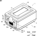
- the container 1 of this embodiment has a rectangular parallelepiped container body 20 having a bottom wall 3 and a side wall 4 as shown in FIGS. 1 and 2, and a lid 10 for closing the accommodation space S (see FIG. 2) of the container body 20. And Further, as shown in FIGS. 2 and 3, the container 1 has a pair of left and right handles 80 (left and right handles in the claims) disposed at opposite positions of the side walls, and the pair of handles And 80 two front and rear belts 90 (front and back belts in the claims).
- the direction of the side wall 4 provided with the handle 80 is the left-right direction
- the direction of the side wall 4 without the handle 80 is the front-back direction
- the side of the accommodation space S is the inside (inward direction)
- the opposite side is Outside (outside).
- the container 1 of this embodiment is a foldable container in which each side wall 4 is connected to the bottom wall 3 in a fallable manner.
- the container 1 of this embodiment is comprised as a cold storage container (or heat retention container) which maintains the temperature of a thing to be stored. Therefore, each member of the lid 10 and the container body 20 is preferably made of foamed resin, and a heat insulating material may be provided on the inner surface of the container or the like.
- the inner surface of the container made of a foamed resin
- the outer surface of the container made of a foamed resin it is possible to improve the impact resistance in addition to the improvement of the heat insulation (cooling and heat retention). It is also possible to partially provide a foamed resin for each member.
- the lid 10 is a member having a rectangular planar shape and a predetermined thickness, as shown in FIGS. 1 and 4A.
- a rectangular annular annular convex portion 11 in which the central portion is recessed is formed, and at the central portion of each short side of the lid 10, a fastening member 12 for fastening the lid 10 and the container body 20 is attached There is.
- the lower surface of the lid 10 is formed with a downwardly projecting lower convex portion 15 having a contour smaller than the contour of the lid 10.
- the container body 20 includes a bottom plate 30 having a rectangular planar shape that constitutes the bottom wall 3, and a pair of left and right side plates 50 and a pair of front and rear side plates 60 that constitute the side wall 4.
- the left and right side plates 50 have the same configuration on the left and right
- the front and rear side plates 60 have the same configuration on the front and rear.
- the width in the front-rear direction of the left and right side plates 50 is shorter than the width in the left-right direction of the front and rear side plates 60.
- the left and right side plates 50 and the front and rear side plates 60 are connected to the bottom plate 30 so as to be upright and fall over, and are foldable.
- the bottom plate 30 has a bottom portion 31 having a rectangular planar shape, and a pair of opposing left and right side peripheral wall portions 33 and a pair of front and rear side peripheral wall portions 34 rising from the periphery of the top surface of the bottom portion 31.
- Connecting members 40 are provided at both ends of the left and right side peripheral wall portions 33 for connecting the left and right side plates 50 so as to be able to stand upright and fall over, and the front and rear side plates 60 can be erected freely over the width near both ends of each front and rear side peripheral wall portion 33
- a connecting member 41 is provided for connecting to the
- the configuration of the connecting member 40 and the connecting member 41 and the configuration of the engaging portion between the peripheral wall portions 33 and 34 and the side plates 50 and 60 may be any known configuration, and the detailed description thereof will be omitted.
- the height of the left and right side peripheral wall portions 33 is lower than that of the front and rear side peripheral wall portions 34.
- a locking portion 33a is formed for locking the locking member 12 of the lid 10 when folded.
- simple structures such as a velcro, a magnet, concavo-convex latching, concavo-convex fitting, can be used.
- the bottom plate 30 is formed on the lower surface thereof in the vicinity of the connection portion of the long side and the short side, and a pair of front and rear convex portions 35a extending in the longitudinal direction near the front and rear side peripheral wall portion 33. It has four corner projections 35b and a central projection 35c formed in the central portion.
- the containers 1 are stacked by the front and rear convex portions 35a, the corner projections 35b, and the central convex portion 35c, they are stacked by fitting with the concave annular convex portion 11 of the central portion formed on the upper surface of the lid 10. The containers 1 are stabilized with each other.
- both grooves 36 extending to both ends in the longitudinal direction are formed on the lower surface of the bottom plate 30, and a belt 90 described later is accommodated in the grooves 36.
- the groove 36 may not have a depth at which the belt 90 is completely accommodated.
- both ends of the groove 36 are notches 36a inclined in the direction of the left and right side peripheral wall portions 33, and a rod-like holding portion 37 for passing and holding the belt 90 is stretched over the notches 36a.
- a concave portion 38 is formed in which a fingertip can be inserted when carrying the container 1 in a folded state (see FIG. 3).
- the left and right side plates 50 are members having a substantially rectangular planar shape, and are configured to be able to be folded in the inward direction of the container 1 by the connecting member 40.
- the width in a front view of the left and right side plates 50 is smaller than the width of the left and right side peripheral wall portion 33 of the bottom plate 30 by about twice the thickness of the front and rear side plates 60. This is to avoid interference between the side plates at the time of folding by the thickness of each of the left and right side plates 50 and the front and rear side plates 60.
- an inner end surface 52 one step lower than the end surface 51 is formed inside the upper end surface 51 of the left and right side plates 50 so as to fit with the lower convex portion 15 of the lid 10.
- the recessed part 57 is formed in the both ends of the right and left side plate 50, and it comes to engage with the convex part 67 of the overhang part 63 of the front and back side plate 60 mentioned later. ing. When the left and right side plates 50 are folded, the left and right side plates 50 do not interfere with the connecting member 41 (see FIGS. 2 and 7).
- FIGS. 6A and 6B On the outer surface of the left and right side plates 50, as shown in FIGS. 6A and 6B, two grooves extending upward from the lower end so as to be continuous with the grooves 36 and the notches 36a of the bottom plate 30 53 are formed. Further, a concave portion 54 deeper than the groove 53 is formed at the upper end of the groove 53 at a substantially intermediate position between the central portion in the height direction and the upper end (but not penetrating into the container). A rod-like holding portion 55 for passing and holding the belt 90 is bridged. A locking portion 56 for locking the locking member 12 of the lid 10 is formed at a central portion near the upper end of the outer surface of the left and right side plates 50. As a structure of the latching
- locking part 56 simple structures, such as a velcro, a magnet, concavo-convex latching, concavo-convex fitting, can be used.
- the front and rear side plates 60 are members having a substantially rectangular planar shape, and are configured to be able to be folded in the inward direction of the container 1 by the connecting member 41.
- the width in the left-right direction of the front and rear side plates 60 is equal to the length of the front and rear side peripheral wall portion 34 of the bottom plate 30.
- An inner end surface 62 lower than the end surface 61 is formed on the inside of the upper end surface 61 of the front and rear side plates 60 so as to be fitted to the lower convex portion 15 of the lid 10. As shown in FIG.
- the height of the upper end surface 61 is the same as the height of the upper end surface 51 of the left and right side plates 50
- the height of the inner end surface 62 is the same as the height of the inner end surface 52 of the left and right side plates 50.
- an overhanging portion 63 slightly overhanging along the left and right side peripheral wall portions 33 of the bottom plate 30 is formed at both ends of the front and rear side plates 60.
- a convex portion 67 is formed on part of the end face.
- the left and right side plates 50 and the front and rear side plates 60 are erected, the end face of the projecting portion 63 and the end face of the left and right side plate 50 are engaged, and the convex portion 67 of the overhanging portion 63 and the concave portion 57 of the left and right side plate 50 are engaged.
- the left and right side plates 50 and the front and back side plates 60 are fixed at the corner of the container body 20 in the vicinity of the position where the concave portion 57 and the convex portion 67 are formed.
- the lock mechanism 100 is formed.
- the belt 90 is a belt-like member made of a material (cloth, rubber, cord, etc.) having a strength capable of supporting the container 1 together with the contents, and as shown in FIG. 2 and FIG. It is routed from the outer surface through the lower surface of the bottom plate 30 to the outer surfaces of the other left and right side plates 50.
- two belts 90 are arranged side by side in the front-rear direction, and are accommodated in the groove 53 and the groove 36 on the lower surface of the bottom plate 30 and the outer surface of the left and right side plates 50, respectively. As shown in FIGS.
- one end and the other end of the two belts 90 pass through the holding portions 37 on the lower surface of the bottom plate 30, respectively, and then upward from the holding portions 55 provided on the left and right side plates 50. And each connected to the end of the handle 80.
- the belt 90 is connected to the handle 80 in a state of being pulled out from the holding portion 55 by a predetermined length.
- the predetermined length of the belt 90 pulled out from the holding portion 55 is half or more of the thickness of the left and right side plates 50. The predetermined length is appropriately set from the thickness of the left and right side plates 50 and the configuration of the connecting member 40 (the position of the rotation shaft, etc.).
- the handle 80 is for carrying the container 1 in the assembled state, and is disposed outside the left and right side plates 50 as shown in FIG.
- the handle 80 is formed by bending a material having the same width as the belt 90 in half along the longitudinal direction (see FIG. 6B), and the belt has two ends (front end and rear end). It is connected with 90.
- the handle 80 of the cloth material is not limited to being folded in two, and may be folded in three, for example.
- a cover can be attached to the handle 80.
- the handle 80 may be made of a material different from the belt 90.
- the handle 80 indirectly supports the load of the container 1 via the belt 90.
- the handle 80 is directly attached to the side wall (the left and right side plates 50 and the like)
- the base portion of the handle 80 is broken, and the load on the container 1 can be reduced.
- the bottom of the container 1 is supported by the two belts, it is also possible to improve the stability when lifted.
- the thickness of the band 90 is drawn thicker than the actual thickness for the sake of clarity.
- the belt 90 wound around the lower surface of the bottom plate 30, the left and right side peripheral wall portions 33, and the outer surfaces of the left and right side plates 50 may be stretched, and the left and right side plates 50 may not be completely overturned.
- the belt 90 of the present embodiment is connected to the handle 80 in a state of being pulled out from the holding portion 55 by a predetermined length (see the symbol d in FIG. 10A) when the left and right side plates 50 stand. Therefore, along with the rotation of the left and right side plates 50, the belt 90 pulled out from the holding portion 55 is pulled back, and increases between the upper outer end P1 of the left and right side peripheral wall 33 and the lower outer end P2 of the left and right side plates 50. By compensating for the distance, the left and right side plates 50 can be completely turned over.
- the front and rear side plates 60 are turned with respect to the bottom plate 30 (the connecting member 41) to be turned over.
- the left and right side plates 50 and the handle 80 are covered by the front and rear side plates 60.
- the lid 10 is placed on the folded front and rear side plates 60, and the fastening member 12 is engaged with the engaging portions 33a of the left and right side peripheral wall portions 33 to complete the folding operation (see FIG. 9). ).
- the lid 10 is first removed, and the front and rear side plates 60 are erected, and then the left and right side plates 50 are erected. And complete the container 1.
- this embodiment can also be implemented in the following modes.
- the pair of handles 80 disposed outside of the two opposite left and right side plates 50 are connected by the belt 90 passing through the lower surface of the bottom plate 30, but the belt 90 is one handle It does not have to be continuous on the lower surface of the bottom plate 30 from the side of 80 to the side of the other handle 80. That is, as shown in the developed view of FIG. 11A, the end of the belt 90 not connected to the handle 80 may be fixed by the fixing member 39 provided on the lower surface of the bottom plate 30.
- two belts 90 are provided, and one end and the other end of the handle 80 are connected to the two belts 90. However, as shown in FIG.
- the container 1 was a rectangular solid thing, it can also be set as other shapes, such as a column shape.
- the right and left grips 80 are provided, but it is also possible to provide only one grip 80 and directly support the container without providing a grip on one side.
- the handle 80 is provided in the direction of the left and right side plates 50, but may be provided in the direction of the front and rear side plates 60.
Abstract
Provided is a container configured so that a load acting on the base of a handle can be reduced. This container provided with a bottom wall, side walls, and a handle is further provided with a belt which is extended from the lower surface of the bottom wall. A side wall is provided with a holding section through which the belt is passed. The handle is connected, above the holding section, to the belt extended out of the holding section.
Description
本発明は、持ち手を備えた容器に関する。
The present invention relates to a container provided with a handle.
従来、商品の輸送等に用いられる容器であって、持ち上げて運搬しやすいよう容器側面に持ち手を備えた容器が知られている。例えば、特許文献1には、矩形の底面部と、底面部の各辺に対応した前後左右の側壁部と、蓋部とを備えた容器(通い箱)であって、左右の側壁部の外側に持ち手が設けられたものが開示されている。
2. Description of the Related Art Conventionally, there is known a container used for transportation of goods and the like, which is provided with a handle on the side of the container so as to be easily lifted and transported. For example, Patent Document 1 shows a container (touring box) including a rectangular bottom portion, front and rear, left and right side wall portions corresponding to each side of the bottom portion, and a lid portion, and the outside of the left and right side wall portions Are disclosed in which a handle is provided.
しかしながら、特許文献1の構成では、容器を持ち上げた際に持ち手の根本(持ち手と側壁部の取付部分)に大きな負荷がかかり、持ち手が外れてしまったり、持ち手と側壁部の取付部分が破損してしまうおそれがあった。
However, in the configuration of Patent Document 1, when the container is lifted, a large load is applied to the root (the attachment portion of the handle and the side wall) of the handle and the handle may come off, or the handle and the side wall are attached There was a possibility that the part might be damaged.
本発明はこのような事情に鑑みてなされたものであり、持ち手の根本にかかる負荷を軽減することの可能な容器を提供するものである。
This invention is made in view of such a situation, and provides the container which can reduce the load applied to the root of a handle.
本発明によれば、底壁、側壁、及び持ち手を備えた容器であって、前記底壁の下面から取り回されるベルトをさらに備え、前記側壁には、前記ベルトを通過させる保持部が設けられており、前記持ち手は、前記保持部の上側において当該保持部から引き出されたベルトと接続されている、容器が提供される。
According to the present invention, the container further includes a bottom wall, a side wall, and a container having a handle, the belt being wound around the lower surface of the bottom wall, and the side wall includes a holding portion for passing the belt. A container is provided, the handle being connected to a belt pulled out of the holder on the upper side of the holder.
本発明によれば、持ち手がベルトに取り付けられ、ベルトが容器の底壁の下面から取り回されて容器底部を保持するよう構成されているため、容器の荷重が容器底部に取り回されたベルトにかかることになり、持ち手の根元にかかる負荷を軽減することが可能となっている。
According to the invention, the load of the container is distributed to the bottom of the container, since the handle is attached to the belt and the belt is configured to be wound around the lower surface of the bottom wall of the container to hold the container bottom. It will be applied to the belt, making it possible to reduce the load on the base of the hand.
以下、本発明の種々の実施形態を例示する。以下に示す実施形態は互いに組み合わせ可能である。
Hereinafter, various embodiments of the present invention will be illustrated. The embodiments shown below can be combined with one another.
好ましくは、前記保持部は、左及び右保持部を備え、前記持ち手は、左及び右持ち手を備え、前記左及び右持ち手は、それぞれ、前記左及び右保持部から引き出され、前記左及び右保持部は、前記側壁において、対向するように設けられる。
Preferably, the holding part comprises left and right holding parts, the holding hand comprises left and right holding hands, and the left and right holding hands are respectively pulled out from the left and right holding parts, The left and right holding portions are provided to face each other on the side wall.
好ましくは、前記ベルトは、一端が左保持部から引き出され、他端が右保持部から引き出される。
Preferably, one end of the belt is pulled out of the left holding portion and the other end is pulled out of the right holding portion.
好ましくは、前記ベルトは、前及び後ベルトを備え、前記保持部は、前保持部及び後保持部を備え、前記前及び後ベルトは、それぞれ、前保持部及び後保持部から引き出され、前記持ち手の前端及び後端は、それぞれ、前記前及び後ベルトと接続されている。
Preferably, the belt includes front and back belts, the holding unit includes a front holding unit and a rear holding unit, and the front and rear belts are respectively pulled out from the front holding unit and the rear holding unit, The front end and the rear end of the handle are connected to the front and rear belts, respectively.
好ましくは、前記底壁は、略矩形の底板を備え、前記側壁は、前記底板の一方の対向する辺に連結された左右側板と、前記底板の他方の対向する辺に連結された前後側板とを備え、前記左右側板のそれぞれに前記保持部が設けられる。
Preferably, the bottom wall includes a substantially rectangular bottom plate, and the side walls include left and right side plates connected to one opposite side of the bottom plate, and front and rear side plates connected to the other opposite side of the bottom plate. And the holding portion is provided on each of the left and right side plates.
好ましくは、前記左右側板と前記前後側板は、それぞれ前記底板に対し起立転倒自在に連結される。
Preferably, the left and right side plates and the front and rear side plates are respectively connected to the bottom plate so as to be able to stand upright.
好ましくは、前記ベルトは、前記左右側板の起立時に、前記保持部から所定の長さ引き出された状態で前記持ち手と接続されるよう構成されている。
Preferably, the belt is configured to be connected to the handle in a state of being pulled out from the holding portion by a predetermined length when the left and right side plates rise.
好ましくは、前記底壁及び前記側壁により形成される収容空間を閉じる蓋を有しており、前記底壁、側壁及び蓋は発泡樹脂により形成される。
Preferably, it has a lid which closes the accommodation space formed of the bottom wall and the side wall, and the bottom wall, the side wall and the lid are formed of a foamed resin.
以下、本発明の実施の形態について、図面を参照しながら詳細に説明する。
Hereinafter, embodiments of the present invention will be described in detail with reference to the drawings.
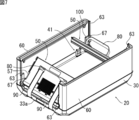
本実施形態の容器1は、図1及び図2に示すように、底壁3及び側壁4を有する直方体形状の容器本体20と、容器本体20の収容空間S(図2参照)を閉じる蓋10とを備える。また、容器1は、図2及び図3に示すように、側壁の対向する位置に配置される左右一対の持ち手80(特許請求の範囲における左及び右持ち手)と、この一対の持ち手80を接続する前後2本のベルト90(特許請求の範囲における前ベルト及び後ベルト)とを備えている。以降の説明において、持ち手80が設けられた側壁4の方向を左右方向、持ち手80のない側壁4の方向を前後方向とし、収容空間Sの側を内側(内方向)、その反対側を外側(外方向)とする。なお、本実施形態の容器1は、底壁3に対して各側壁4が転倒自在に連結された折り畳み式の容器となっている。また、本実施形態の容器1は、収容物の温度を保つ保冷容器(又は保温容器)として構成される。そのため、蓋10及び容器本体20の各部材は、発泡樹脂製とすることが好ましく、さらに容器内面等に断熱材を設けても良い。容器内面を発泡樹脂製とすることで、断熱性(保冷、保温)の向上に加え、内容物が容器とぶつかる際のクッション性を向上させることが可能となる。また、容器外面を発泡樹脂製とすることで、断熱性(保冷、保温)の向上に加えて、耐衝撃性を向上させることが可能となる。また、各部材について発泡樹脂を部分的に設けることも可能である。
The container 1 of this embodiment has a rectangular parallelepiped container body 20 having a bottom wall 3 and a side wall 4 as shown in FIGS. 1 and 2, and a lid 10 for closing the accommodation space S (see FIG. 2) of the container body 20. And Further, as shown in FIGS. 2 and 3, the container 1 has a pair of left and right handles 80 (left and right handles in the claims) disposed at opposite positions of the side walls, and the pair of handles And 80 two front and rear belts 90 (front and back belts in the claims). In the following description, the direction of the side wall 4 provided with the handle 80 is the left-right direction, the direction of the side wall 4 without the handle 80 is the front-back direction, the side of the accommodation space S is the inside (inward direction), and the opposite side is Outside (outside). In addition, the container 1 of this embodiment is a foldable container in which each side wall 4 is connected to the bottom wall 3 in a fallable manner. Moreover, the container 1 of this embodiment is comprised as a cold storage container (or heat retention container) which maintains the temperature of a thing to be stored. Therefore, each member of the lid 10 and the container body 20 is preferably made of foamed resin, and a heat insulating material may be provided on the inner surface of the container or the like. By making the inner surface of the container made of a foamed resin, it is possible to improve the cushioning property when the contents collide with the container, in addition to the improvement of the heat insulation (cooling and heat retention). Further, by making the outer surface of the container made of a foamed resin, it is possible to improve the impact resistance in addition to the improvement of the heat insulation (cooling and heat retention). It is also possible to partially provide a foamed resin for each member.
蓋10は、図1及び図4Aに示すように、平面形状が長方形で、所定の厚さを有する部材である。蓋10の上面には、中央部分が凹んだ矩形環状の環状凸部11が形成され、蓋10の各短辺の中央部分には、蓋10と容器本体20を留める留め部材12が取り付けられている。また、図4Aに示すように、蓋10の下面には、蓋10の輪郭よりも一回り小さい輪郭の、下方に突出する下凸部15が形成されている。
The lid 10 is a member having a rectangular planar shape and a predetermined thickness, as shown in FIGS. 1 and 4A. On the upper surface of the lid 10, a rectangular annular annular convex portion 11 in which the central portion is recessed is formed, and at the central portion of each short side of the lid 10, a fastening member 12 for fastening the lid 10 and the container body 20 is attached There is. Further, as shown in FIG. 4A, the lower surface of the lid 10 is formed with a downwardly projecting lower convex portion 15 having a contour smaller than the contour of the lid 10.
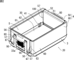
容器本体20は、図2に示すように、底壁3を構成する平面形状が長方形の底板30と、側壁4を構成する、一対の左右側板50及び一対の前後側板60と、を備える。ここで、左右側板50は左右で同一の構成であり、前後側板60は、前後で同一の構成である。なお、本実施形態において、左右側板50の前後方向の幅は、前後側板60の左右方向の幅よりも短くなっている。また、左右側板50及び前後側板60は、底板30に対し起立転倒自在に連結され、折り畳み可能となっている。
As shown in FIG. 2, the container body 20 includes a bottom plate 30 having a rectangular planar shape that constitutes the bottom wall 3, and a pair of left and right side plates 50 and a pair of front and rear side plates 60 that constitute the side wall 4. Here, the left and right side plates 50 have the same configuration on the left and right, and the front and rear side plates 60 have the same configuration on the front and rear. In the present embodiment, the width in the front-rear direction of the left and right side plates 50 is shorter than the width in the left-right direction of the front and rear side plates 60. Further, the left and right side plates 50 and the front and rear side plates 60 are connected to the bottom plate 30 so as to be upright and fall over, and are foldable.
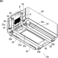
底板30は、図5に示すように、平面形状が長方形の底部31と、底部31上面の周囲から立ち上がった対向する一対の左右側周壁部33及び一対の前後側周壁部34とを有する。各左右側周壁部33の両端部には、左右側板50を起立転倒自在に連結する連結部材40が設けられ、各前後側周壁部33の両端部近傍幅には、前後側板60を起立転倒自在に連結する連結部材41が設けられている。連結部材40及び連結部材41の構成、また周壁部33,34と側板50,60との係合部分の構成については、既知である任意の構成とすることができ、その詳細な説明は省略する。また、左右側周壁部33の高さは、前後側周壁部34よりもが低くなっている。これは、容器本体20を折り畳む際に、先に左右側板50を折り畳み、折り畳まれた左右側板50の上に前後側板60を折り畳むためである(図7参照)。なお、左右側周壁部33の外面中央部分には、折り畳んだ際に蓋10の留め部材12を係止する係止部33aが形成されている。係止部33aの構成としては、マジックテープや磁石、凹凸係止、凹凸嵌合などの簡易な構成を用いることができる。
As shown in FIG. 5, the bottom plate 30 has a bottom portion 31 having a rectangular planar shape, and a pair of opposing left and right side peripheral wall portions 33 and a pair of front and rear side peripheral wall portions 34 rising from the periphery of the top surface of the bottom portion 31. Connecting members 40 are provided at both ends of the left and right side peripheral wall portions 33 for connecting the left and right side plates 50 so as to be able to stand upright and fall over, and the front and rear side plates 60 can be erected freely over the width near both ends of each front and rear side peripheral wall portion 33 A connecting member 41 is provided for connecting to the The configuration of the connecting member 40 and the connecting member 41 and the configuration of the engaging portion between the peripheral wall portions 33 and 34 and the side plates 50 and 60 may be any known configuration, and the detailed description thereof will be omitted. . Further, the height of the left and right side peripheral wall portions 33 is lower than that of the front and rear side peripheral wall portions 34. This is because when folding the container main body 20, the left and right side plates 50 are first folded, and the front and rear side plates 60 are folded on the folded left and right side plates 50 (see FIG. 7). At the center of the outer surface of the left and right side peripheral wall portion 33, a locking portion 33a is formed for locking the locking member 12 of the lid 10 when folded. As a structure of the latching | locking part 33a, simple structures, such as a velcro, a magnet, concavo-convex latching, concavo-convex fitting, can be used.
また、底板30は、図3に示すように、その下面に、前後側周壁部33の近傍において長手方向に延びる一対の前後凸部35aと、長辺と短辺の接続部近傍に形成される4つの隅部突起35bと、中央部分に形成される中央凸部35cとを備える。これら前後凸部35a、隅部突起35b、中央凸部35cにより、容器1を積み重ねる際に、蓋10の上面に形成された中央部分の凹んだ環状凸部11と嵌り合うことで、積み重ねられた容器1同士が安定するようになっている。
Further, as shown in FIG. 3, the bottom plate 30 is formed on the lower surface thereof in the vicinity of the connection portion of the long side and the short side, and a pair of front and rear convex portions 35a extending in the longitudinal direction near the front and rear side peripheral wall portion 33. It has four corner projections 35b and a central projection 35c formed in the central portion. When the containers 1 are stacked by the front and rear convex portions 35a, the corner projections 35b, and the central convex portion 35c, they are stacked by fitting with the concave annular convex portion 11 of the central portion formed on the upper surface of the lid 10. The containers 1 are stabilized with each other.
加えて、底板30の下面には、図6Aに示すように、長手方向に亘って両端まで延びる2本の溝36が形成され、この溝36に後述するベルト90が収容されるようになっている。ベルト90を収容する溝36を備えていることにより、容器1を床面に載置した際のベルト90への負荷を低減してベルト90の傷みを抑制することができ、また、容器1を安定して床面に載置することができる。なお、溝36は、ベルト90が完全に収容される深さとしなくてもよい。また、溝36の両端部は、左右側周壁部33方向に傾斜する切り欠き36aとなっており、切り欠き36aにはベルト90を通過させて保持する棒状の保持部37が架け渡されている。さらに、底板30下面の左右側周壁部33との境界付近中央部には、容器1を折り畳んだ状態で持ち運ぶ際に指先を入れることのできる凹部38が形成されている(図3参照)。
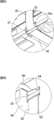
In addition, as shown in FIG. 6A, two grooves 36 extending to both ends in the longitudinal direction are formed on the lower surface of the bottom plate 30, and a belt 90 described later is accommodated in the grooves 36. There is. By providing the groove 36 for accommodating the belt 90, it is possible to reduce the load on the belt 90 when the container 1 is placed on the floor surface and to suppress the damage of the belt 90. It can be stably placed on the floor. The groove 36 may not have a depth at which the belt 90 is completely accommodated. Further, both ends of the groove 36 are notches 36a inclined in the direction of the left and right side peripheral wall portions 33, and a rod-like holding portion 37 for passing and holding the belt 90 is stretched over the notches 36a. . Furthermore, at the central portion near the boundary with the left and right side peripheral wall portion 33 on the bottom surface of the bottom plate 30, a concave portion 38 is formed in which a fingertip can be inserted when carrying the container 1 in a folded state (see FIG. 3).
左右側板50は、図2~図4に示すように、平面形状が略長方形の部材であり、連結部材40により容器1の内側方向に折り畳むことができるよう構成される。左右側板50の正面視における幅は、底板30の左右側周壁部33の幅よりも、前後側板60の厚さの2倍程度短くなっている。これは、左右側板50と前後側板60それぞれの厚さにより、折り畳み時にこれら側板同士の干渉を避けるためである。また、図2に示すように、左右側板50の上端面51の内側には、蓋10の下凸部15と嵌り合うよう、同端面51よりも一段低い内側端面52が形成されている。加えて、図2及び図4B等に示すように、左右側板50の両端部には凹部57が形成されており、後述する前後側板60の張り出し部63の凸部67と係合するようになっている。なお、この凹部57により、左右側板50を折り畳んだ際に、左右側板50と連結部材41が干渉しないようになっている(図2及び図7参照)。
The left and right side plates 50, as shown in FIGS. 2 to 4, are members having a substantially rectangular planar shape, and are configured to be able to be folded in the inward direction of the container 1 by the connecting member 40. The width in a front view of the left and right side plates 50 is smaller than the width of the left and right side peripheral wall portion 33 of the bottom plate 30 by about twice the thickness of the front and rear side plates 60. This is to avoid interference between the side plates at the time of folding by the thickness of each of the left and right side plates 50 and the front and rear side plates 60. Further, as shown in FIG. 2, an inner end surface 52 one step lower than the end surface 51 is formed inside the upper end surface 51 of the left and right side plates 50 so as to fit with the lower convex portion 15 of the lid 10. In addition, as shown in FIG. 2 and FIG. 4B etc., the recessed part 57 is formed in the both ends of the right and left side plate 50, and it comes to engage with the convex part 67 of the overhang part 63 of the front and back side plate 60 mentioned later. ing. When the left and right side plates 50 are folded, the left and right side plates 50 do not interfere with the connecting member 41 (see FIGS. 2 and 7).
左右側板50の外面には、図6A及び図6Bに示すように、底板30の溝36及び切り欠き36aと連続するよう下端から上方向に向かって延び、ベルト90が収容される2本の溝53が形成されている。また、溝53の上端であって高さ方向の中央部と上端との略中間位置には、溝53よりも深い凹部54が形成され(ただし容器内部には貫通しない)、凹部54には、ベルト90を通過させて保持する棒状の保持部55が架け渡されている。なお、左右側板50の外面上端近傍の中央部分には、蓋10の留め部材12を係止する係止部56が形成されている。係止部56の構成としては、マジックテープや磁石、凹凸係止、凹凸嵌合などの簡易な構成を用いることができる。
On the outer surface of the left and right side plates 50, as shown in FIGS. 6A and 6B, two grooves extending upward from the lower end so as to be continuous with the grooves 36 and the notches 36a of the bottom plate 30 53 are formed. Further, a concave portion 54 deeper than the groove 53 is formed at the upper end of the groove 53 at a substantially intermediate position between the central portion in the height direction and the upper end (but not penetrating into the container). A rod-like holding portion 55 for passing and holding the belt 90 is bridged. A locking portion 56 for locking the locking member 12 of the lid 10 is formed at a central portion near the upper end of the outer surface of the left and right side plates 50. As a structure of the latching | locking part 56, simple structures, such as a velcro, a magnet, concavo-convex latching, concavo-convex fitting, can be used.
前後側板60は、平面形状が略長方形の部材であり、連結部材41により容器1の内側方向に折り畳むことができるよう構成される。前後側板60の左右方向の幅は、底板30の前後側周壁部34の長さと等しい。前後側板60の上端面61の内側には、蓋10の下凸部15と嵌り合うよう、同端面61よりも低い内側端面62が形成されている。図2に示すように、上端面61の高さは、左右側板50の上端面51の高さと同じであり、内側端面62の高さは、左右側板50の内側端面52の高さと同じである。また、図2及び図7等に示すように、前後側板60の両側端部には、底板30の左右側周壁部33に沿ってやや張り出した張り出し部63が形成されており、張り出し部63の端面の一部には凸部67が形成されている。そして、左右側板50及び前後側板60の起立時には、張り出し部63の端面と左右側板50の端面とが係合し、張り出し部63の凸部67と左右側板50の凹部57とが係合するよう構成される。また、詳細な説明は省略するが、容器本体20には、これら凹部57及び凸部67の形成された位置の近傍に、起立した左右側板50と前後側板60とを容器本体20の隅で固定するロック機構100が形成されている。
The front and rear side plates 60 are members having a substantially rectangular planar shape, and are configured to be able to be folded in the inward direction of the container 1 by the connecting member 41. The width in the left-right direction of the front and rear side plates 60 is equal to the length of the front and rear side peripheral wall portion 34 of the bottom plate 30. An inner end surface 62 lower than the end surface 61 is formed on the inside of the upper end surface 61 of the front and rear side plates 60 so as to be fitted to the lower convex portion 15 of the lid 10. As shown in FIG. 2, the height of the upper end surface 61 is the same as the height of the upper end surface 51 of the left and right side plates 50, and the height of the inner end surface 62 is the same as the height of the inner end surface 52 of the left and right side plates 50. . Further, as shown in FIG. 2 and FIG. 7 etc., an overhanging portion 63 slightly overhanging along the left and right side peripheral wall portions 33 of the bottom plate 30 is formed at both ends of the front and rear side plates 60. A convex portion 67 is formed on part of the end face. Then, when the left and right side plates 50 and the front and rear side plates 60 are erected, the end face of the projecting portion 63 and the end face of the left and right side plate 50 are engaged, and the convex portion 67 of the overhanging portion 63 and the concave portion 57 of the left and right side plate 50 are engaged. Configured Although detailed description is omitted, the left and right side plates 50 and the front and back side plates 60 are fixed at the corner of the container body 20 in the vicinity of the position where the concave portion 57 and the convex portion 67 are formed. The lock mechanism 100 is formed.
ベルト90は、容器1を収容物とともに支持できる強度を備えた素材(布、ゴム、ひも、など)からなる帯状の部材であり、図2及び図3に示すように、一方の左右側板50の外面から底板30の下面を通って他方の左右側板50の外面まで取り回されている。本実施形態では、ベルト90は前後方向に2本並ぶよう配置されており、底板30の下面及び左右側板50の外面において、それぞれ溝53及び溝36に収容されている。2本のベルト90の一端及び他端は、図6A及び図6Bに示すように、それぞれ底板30の下面において保持部37を通されたあと、左右側板50に設けられた保持部55から上方向に引き出され、それぞれ持ち手80の端部に接続される。なお、ベルト90は、左右側板50の起立時に、保持部55から所定の長さだけ引き出された状態で持ち手80と接続される長さとされる。本実施形態において、保持部55から引き出されるベルト90の所定の長さは、左右側板50の厚みの半分以上とされる。この所定の長さは、左右側板50の厚みと連結部材40の構成(回転軸の位置等)から適宜設定される。
The belt 90 is a belt-like member made of a material (cloth, rubber, cord, etc.) having a strength capable of supporting the container 1 together with the contents, and as shown in FIG. 2 and FIG. It is routed from the outer surface through the lower surface of the bottom plate 30 to the outer surfaces of the other left and right side plates 50. In the present embodiment, two belts 90 are arranged side by side in the front-rear direction, and are accommodated in the groove 53 and the groove 36 on the lower surface of the bottom plate 30 and the outer surface of the left and right side plates 50, respectively. As shown in FIGS. 6A and 6B, one end and the other end of the two belts 90 pass through the holding portions 37 on the lower surface of the bottom plate 30, respectively, and then upward from the holding portions 55 provided on the left and right side plates 50. And each connected to the end of the handle 80. When the left and right side plates 50 are erected, the belt 90 is connected to the handle 80 in a state of being pulled out from the holding portion 55 by a predetermined length. In the present embodiment, the predetermined length of the belt 90 pulled out from the holding portion 55 is half or more of the thickness of the left and right side plates 50. The predetermined length is appropriately set from the thickness of the left and right side plates 50 and the configuration of the connecting member 40 (the position of the rotation shaft, etc.).
持ち手80は、組み立てた状態の容器1を持ち運ぶためのものであり、図1等に示すように、左右側板50の外側に配置される。本実施形態において、持ち手80はベルト90と同一幅の素材を長手方向に沿って半分に折り曲げて形成されたものであり(図6B参照)、両端(前端及び後端)が2本のベルト90と接続されている。言い換えると、2つの保持部55から引き出された2本のベルト90が、持ち手80により接続されていると言え、これにより、ベルト90が保持部55から抜けて外れてしまうことが防止されている。なお、布素材の持ち手80は2つ折りに限定されず、3つ折りなど、折り曲げ方を変更しても良い。また、持ち手80には、カバーを取り付けることも可能である。さらに、持ち手80を、ベルト90と別の素材で構成しても良い。
The handle 80 is for carrying the container 1 in the assembled state, and is disposed outside the left and right side plates 50 as shown in FIG. In the present embodiment, the handle 80 is formed by bending a material having the same width as the belt 90 in half along the longitudinal direction (see FIG. 6B), and the belt has two ends (front end and rear end). It is connected with 90. In other words, it can be said that the two belts 90 pulled out from the two holding parts 55 are connected by the handle 80, thereby preventing the belt 90 from coming off the holding parts 55 and coming off There is. In addition, the handle 80 of the cloth material is not limited to being folded in two, and may be folded in three, for example. In addition, a cover can be attached to the handle 80. Furthermore, the handle 80 may be made of a material different from the belt 90.
以上のように、本実施形態の容器1は、持ち上げられた際に、持ち手80が容器1の荷重をベルト90を介して間接的に支持することになるため、持ち手80が容器1の側壁(左右側板50等)に直接取り付けられる構成と比較して、持ち手80の付け根部分が破損するおそれがなく、容器1への負荷を低減することが可能になっている。また、2本のベルトにより容器1の底部を支持することになるため、持ち上げた際の安定性を向上させることも可能となっている。
As described above, when the container 1 of the present embodiment is lifted, the handle 80 indirectly supports the load of the container 1 via the belt 90. As compared with the configuration in which the handle 80 is directly attached to the side wall (the left and right side plates 50 and the like), there is no possibility that the base portion of the handle 80 is broken, and the load on the container 1 can be reduced. Further, since the bottom of the container 1 is supported by the two belts, it is also possible to improve the stability when lifted.
次に、図7~図10Cを参照して、容器1の折り畳み及び組み立ての動作について説明する。なお、図10A~図10Cにおいては、わかりやすくするために、バンド90の厚みを実際よりも厚く描いている。
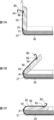
The operation of folding and assembling the container 1 will now be described with reference to FIGS. 7 to 10C. 10A to 10C, the thickness of the band 90 is drawn thicker than the actual thickness for the sake of clarity.
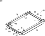
容器1を折り畳む際は、蓋10を外した状態で、図7に示すように、まず、ロック機構100による左右側板50と前後側板60の固定を解除し、左右側板50を底板30(連結部材40)に対して回動させて転倒させる。このとき、左右側板50の回動に伴って、ほとんど当接していた底板30の左右側周壁部33の上端外側P1と左右側板50の下端外側P2(図10A参照)との間の距離が、徐々に離れていくことになる(図10B及び図10C参照)。そのため、底板30の下面、左右側周壁部33及び左右側板50の外面に取り回されたベルト90が張ってしまい、左右側板50を完全に転倒させられないおそれがある。しかしながら、本実施形態のベルト90は、左右側板50の起立時に、保持部55から所定の長さ(図10Aの符号d参照)だけ引き出された状態で持ち手80と接続されている。したがって、左右側板50の回動に伴って、保持部55から引き出されていたベルト90が引き戻されて、左右側周壁部33の上端外側P1と左右側板50の下端外側P2との間の増加した距離分を補うことで、左右側板50を完全に転倒させることができるようになっている。
When the container 1 is folded, with the lid 10 removed, as shown in FIG. 7, first, the fixation of the left and right side plates 50 and the front and back side plates 60 by the lock mechanism 100 is released, and the left and right side plates 50 40) Rotate it over and turn over. At this time, with the rotation of the left and right side plates 50, the distance between the upper outer end P1 of the left and right side peripheral wall portion 33 of the bottom plate 30 and the lower outer end P2 of the left and right side plates 50 (see FIG. 10A) It will be gradually separated (see FIGS. 10B and 10C). Therefore, the belt 90 wound around the lower surface of the bottom plate 30, the left and right side peripheral wall portions 33, and the outer surfaces of the left and right side plates 50 may be stretched, and the left and right side plates 50 may not be completely overturned. However, the belt 90 of the present embodiment is connected to the handle 80 in a state of being pulled out from the holding portion 55 by a predetermined length (see the symbol d in FIG. 10A) when the left and right side plates 50 stand. Therefore, along with the rotation of the left and right side plates 50, the belt 90 pulled out from the holding portion 55 is pulled back, and increases between the upper outer end P1 of the left and right side peripheral wall 33 and the lower outer end P2 of the left and right side plates 50. By compensating for the distance, the left and right side plates 50 can be completely turned over.
上記のようにして左右側板50を完全に転倒させた後、次に、前後側板60を底板30(連結部材41)に対して回動させて転倒させる。このとき、図8に示すように、左右側板50及び持ち手80は前後側板60により覆われることになる。そして、最後に、蓋10を折り畳んだ前後側板60の上に載置し、留め部材12を左右側周壁部33の係止部33aに係止することで、折り畳み動作が完了する(図9参照)。
After the left and right side plates 50 are completely turned over as described above, next, the front and rear side plates 60 are turned with respect to the bottom plate 30 (the connecting member 41) to be turned over. At this time, as shown in FIG. 8, the left and right side plates 50 and the handle 80 are covered by the front and rear side plates 60. Finally, the lid 10 is placed on the folded front and rear side plates 60, and the fastening member 12 is engaged with the engaging portions 33a of the left and right side peripheral wall portions 33 to complete the folding operation (see FIG. 9). ).
一方、容器1を組み立て時は、上記とは逆に、まず蓋10を外し、前後側板60を起立させた後、左右側板50を起立させ、ロック機構100により左右側板50及び前後側板60を固定して、容器1を完成させる。
On the other hand, when the container 1 is assembled, the lid 10 is first removed, and the front and rear side plates 60 are erected, and then the left and right side plates 50 are erected. And complete the container 1.
なお、本実施形態は、以下の態様でも実施可能である。
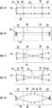
・上記実施形態では、向かい合う2つの左右側板50の外方に配置される一対の持ち手80が底板30の下面を通るベルト90により接続される構成であったが、ベルト90は一方の持ち手80の側から他方の持ち手80の側まで底板30の下面において連続していなくても良い。すなわち、図11Aの展開図に示すように、ベルト90の持ち手80と接続されない側の端部を、底板30の下面に設けられた固定部材39により固定する構成とすることも可能である。
・また、上記実施形態では、ベルト90は2本設けられ、これら2本のベルト90に持ち手80の一端及び他端がそれぞれ接続される構成であったが、図11Bに示すように、ベルト90を1本とし、ベルト90の端部を環状の持ち手80と接続するような構成とすることも可能である。なお、ベルト90の数を3本以上とすることも可能である。
・加えて、図11C及び図11Dに示すように、2本のベルト90を交差させて配置することも可能である。
・さらに、図11Eに示すように、1つの持ち手80に2つのベルト90を接続し、2つのベルト90の他端をそれぞれ底板30の下面に設けられた固定部材39により固定する構成とすることも可能である。
・上記実施形態では、容器1は直方体形状のものであったが、円柱形等、他の形状とすることもできる。
・上記実施形態では、持ち手80は左右一対設けられていたが、持ち手80を1つだけ設け、一方側には持ち手を設けず容器を直接支える構成とすることも可能である。
・上記に示した形態のうち、1本のベルト90を左右の持ち手80に接続させる形態(図3、図11B、図11Cの形態)においては、ベルト90が左右にずれることを防ぐため、底板30の下面(溝38)にベルトのずれを防止するズレ防止部を設けることが好適である。
・上記実施形態では、持ち手80を左右側板50の方向に設けていたが、前後側板60の方向に設けても良い。 In addition, this embodiment can also be implemented in the following modes.
In the above embodiment, the pair ofhandles 80 disposed outside of the two opposite left and right side plates 50 are connected by the belt 90 passing through the lower surface of the bottom plate 30, but the belt 90 is one handle It does not have to be continuous on the lower surface of the bottom plate 30 from the side of 80 to the side of the other handle 80. That is, as shown in the developed view of FIG. 11A, the end of the belt 90 not connected to the handle 80 may be fixed by the fixing member 39 provided on the lower surface of the bottom plate 30.
In the above embodiment, twobelts 90 are provided, and one end and the other end of the handle 80 are connected to the two belts 90. However, as shown in FIG. It is also possible to use one 90 and connect the end of the belt 90 with the annular handle 80. The number of belts 90 may be three or more.
In addition, as shown in FIGS. 11C and 11D, it is also possible to arrange twobelts 90 crossing each other.
Further, as shown in FIG. 11E, twobelts 90 are connected to one handle 80, and the other ends of the two belts 90 are fixed by fixing members 39 provided on the lower surface of the bottom plate 30, respectively. It is also possible.
-In the said embodiment, although thecontainer 1 was a rectangular solid thing, it can also be set as other shapes, such as a column shape.
In the embodiment described above, the right and leftgrips 80 are provided, but it is also possible to provide only one grip 80 and directly support the container without providing a grip on one side.
-In the form (one of FIG. 3, FIG. 11B and FIG. 11C) in which onebelt 90 is connected to the left and right grips 80 among the forms shown above, in order to prevent the belt 90 from shifting to the left and right, It is preferable to provide a displacement preventing portion on the lower surface (groove 38) of the bottom plate 30 for preventing displacement of the belt.
In the above embodiment, thehandle 80 is provided in the direction of the left and right side plates 50, but may be provided in the direction of the front and rear side plates 60.
・上記実施形態では、向かい合う2つの左右側板50の外方に配置される一対の持ち手80が底板30の下面を通るベルト90により接続される構成であったが、ベルト90は一方の持ち手80の側から他方の持ち手80の側まで底板30の下面において連続していなくても良い。すなわち、図11Aの展開図に示すように、ベルト90の持ち手80と接続されない側の端部を、底板30の下面に設けられた固定部材39により固定する構成とすることも可能である。
・また、上記実施形態では、ベルト90は2本設けられ、これら2本のベルト90に持ち手80の一端及び他端がそれぞれ接続される構成であったが、図11Bに示すように、ベルト90を1本とし、ベルト90の端部を環状の持ち手80と接続するような構成とすることも可能である。なお、ベルト90の数を3本以上とすることも可能である。
・加えて、図11C及び図11Dに示すように、2本のベルト90を交差させて配置することも可能である。
・さらに、図11Eに示すように、1つの持ち手80に2つのベルト90を接続し、2つのベルト90の他端をそれぞれ底板30の下面に設けられた固定部材39により固定する構成とすることも可能である。
・上記実施形態では、容器1は直方体形状のものであったが、円柱形等、他の形状とすることもできる。
・上記実施形態では、持ち手80は左右一対設けられていたが、持ち手80を1つだけ設け、一方側には持ち手を設けず容器を直接支える構成とすることも可能である。
・上記に示した形態のうち、1本のベルト90を左右の持ち手80に接続させる形態(図3、図11B、図11Cの形態)においては、ベルト90が左右にずれることを防ぐため、底板30の下面(溝38)にベルトのずれを防止するズレ防止部を設けることが好適である。
・上記実施形態では、持ち手80を左右側板50の方向に設けていたが、前後側板60の方向に設けても良い。 In addition, this embodiment can also be implemented in the following modes.
In the above embodiment, the pair of
In the above embodiment, two
In addition, as shown in FIGS. 11C and 11D, it is also possible to arrange two
Further, as shown in FIG. 11E, two
-In the said embodiment, although the
In the embodiment described above, the right and left
-In the form (one of FIG. 3, FIG. 11B and FIG. 11C) in which one
In the above embodiment, the
1:容器、3:底壁、4:側壁、10:蓋、11:環状凸部、12:留め部材、15:下凸部、20:容器本体、30:底板、31:底部、33:前後側周壁部、33a:係止部、34:左右側周壁部、35a:前後凸部、35b:隅部突起、35c:中央凸部、36,53:溝、36a:切り欠き、37,55:保持部、38,54,57:凹部、39:固定部材、40,41:連結部材、50:左右側板、51:上端面、52:内側端面、56:係止部、60:前後側板、61:上端面、62:内側端面、63:張り出し部、67:凸部、80:持ち手、90:ベルト、100:ロック機構、P1:上端外側、P2:下端外側、S:収容空間
1: container, 3: bottom wall, 4: side wall, 10: lid, 11: annular convex portion, 12: fastening member, 15: lower convex portion, 20: container main body, 30: bottom plate, 31: bottom, 33: front and rear Side peripheral wall portion 33a: Locking portion 34: Left and right side peripheral wall portions 35a: Front and rear convex portions 35b: Corner projection 35c: Central convex portion 36, 53: Groove 36a: Notched 37, 55: Holding part, 38, 54, 57: Recess, 39: Fixing member, 40, 41: Connecting member, 50: Left and right side plates, 51: Upper end face, 52: Inner end face, 56: Locking part, 60: Front and back side plate, 61 : Upper end face, 62: inner end face, 63: projecting portion, 67: convex portion, 80: handle, 90: belt, 100: locking mechanism, P1: upper end outside, P2: lower end outside, S: accommodation space
Claims (8)
- 底壁、側壁、及び持ち手を備えた容器であって、
前記底壁の下面から取り回されるベルトをさらに備え、
前記側壁には、前記ベルトを通過させる保持部が設けられており、
前記持ち手は、前記保持部の上側において当該保持部から引き出されたベルトと接続されている、容器。 A container having a bottom wall, a side wall, and a handle,
The belt further comprises a belt routed from the lower surface of the bottom wall,
The side wall is provided with a holding portion for passing the belt.
The container, wherein the handle is connected to a belt pulled out from the holding portion on the upper side of the holding portion. - 前記保持部は、左及び右保持部を備え、
前記持ち手は、左及び右持ち手を備え、
前記左及び右持ち手は、それぞれ、前記左及び右保持部から引き出され、
前記左及び右保持部は、前記側壁において、対向するように設けられる、請求項1に記載の容器。 The holding unit includes left and right holding units.
The handle comprises a left and a right handle,
The left and right handles are pulled out from the left and right holders, respectively
The container according to claim 1, wherein the left and right holding portions are provided to face each other on the side wall. - 前記ベルトは、一端が左保持部から引き出され、他端が右保持部から引き出される、請求項2に記載の容器。 The container according to claim 2, wherein the belt is pulled out from the left holding portion at one end and from the right holding portion at the other end.
- 前記ベルトは、前及び後ベルトを備え、
前記保持部は、前保持部及び後保持部を備え、
前記前及び後ベルトは、それぞれ、前保持部及び後保持部から引き出され、
前記持ち手の前端及び後端は、それぞれ、前記前及び後ベルトと接続されている、請求項1~請求項3のいずれかに記載の容器。 The belts include front and back belts.
The holding unit includes a front holding unit and a rear holding unit.
The front and rear belts are respectively pulled out from the front holding portion and the rear holding portion,
The container according to any one of claims 1 to 3, wherein the front end and the rear end of the handle are connected to the front and rear belts, respectively. - 前記底壁は、略矩形の底板を備え、
前記側壁は、前記底板の一方の対向する辺に連結された左右側板と、前記底板の他方の対向する辺に連結された前後側板とを備え、
前記左右側板のそれぞれに前記保持部が設けられる、請求項1~請求項4のいずれかに記載の容器。 The bottom wall comprises a substantially rectangular bottom plate,
The side wall includes left and right side plates connected to one opposing side of the bottom plate, and front and rear side plates connected to the other opposing side of the bottom plate.
The container according to any one of claims 1 to 4, wherein the holding portion is provided on each of the left and right side plates. - 前記左右側板と前記前後側板は、それぞれ前記底板に対し起立転倒自在に連結される、請求項5に記載の容器。 The container according to claim 5, wherein the left and right side plates and the front and rear side plates are respectively connected to the bottom plate so as to be upright and fall over.
- 前記ベルトは、前記左右側板の起立時に、前記保持部から所定の長さ引き出された状態で前記持ち手と接続されるよう構成されている、請求項6に記載の容器。 The container according to claim 6, wherein the belt is configured to be connected to the handle in a state of being pulled out from the holding portion by a predetermined length when the left and right side plates rise.
- 前記底壁及び前記側壁により形成される収容空間を閉じる蓋を有しており、前記底壁、側壁及び蓋は発泡樹脂により形成される、請求項1~請求項7のいずれかに記載の容器。 The container according to any one of claims 1 to 7, further comprising: a lid for closing the storage space formed by the bottom wall and the side wall, wherein the bottom wall, the side wall and the lid are formed of a foamed resin. .
Applications Claiming Priority (2)
| Application Number | Priority Date | Filing Date | Title |
|---|---|---|---|
| JP2017155589A JP6889370B2 (en) | 2017-08-10 | 2017-08-10 | container |
| JP2017-155589 | 2017-08-10 |
Publications (1)
| Publication Number | Publication Date |
|---|---|
| WO2019031476A1 true WO2019031476A1 (en) | 2019-02-14 |
Family
ID=65272014
Family Applications (1)
| Application Number | Title | Priority Date | Filing Date |
|---|---|---|---|
| PCT/JP2018/029525 WO2019031476A1 (en) | 2017-08-10 | 2018-08-07 | Container |
Country Status (2)
| Country | Link |
|---|---|
| JP (1) | JP6889370B2 (en) |
| WO (1) | WO2019031476A1 (en) |
Families Citing this family (1)
| Publication number | Priority date | Publication date | Assignee | Title |
|---|---|---|---|---|
| US20220143252A1 (en) | 2019-02-27 | 2022-05-12 | Canon Kabushiki Kaisha | Management system for managing sterilization process record, information processing apparatus, management method, and computer-readable storage medium |
Citations (7)
| Publication number | Priority date | Publication date | Assignee | Title |
|---|---|---|---|---|
| JPS5186330U (en) * | 1974-12-27 | 1976-07-10 | ||
| JPS642788U (en) * | 1987-06-25 | 1989-01-10 | ||
| JPH0542144U (en) * | 1991-06-26 | 1993-06-08 | 鐘淵化学工業株式会社 | Insulated container with hand strap |
| JPH11263346A (en) * | 1998-03-18 | 1999-09-28 | Daiko Shiki:Kk | Hanging box for transportation |
| JP2001322637A (en) * | 2000-05-16 | 2001-11-20 | Sanko Co Ltd | Collapsible container |
| JP2002104426A (en) * | 2000-09-27 | 2002-04-10 | Kanegafuchi Chem Ind Co Ltd | Container with hand bascket string |
| US7815024B1 (en) * | 2007-04-02 | 2010-10-19 | Quimpo Wilfredo B | Collapsible balikbayan box apparatus |
-
2017
- 2017-08-10 JP JP2017155589A patent/JP6889370B2/en active Active
-
2018
- 2018-08-07 WO PCT/JP2018/029525 patent/WO2019031476A1/en active Application Filing
Patent Citations (7)
| Publication number | Priority date | Publication date | Assignee | Title |
|---|---|---|---|---|
| JPS5186330U (en) * | 1974-12-27 | 1976-07-10 | ||
| JPS642788U (en) * | 1987-06-25 | 1989-01-10 | ||
| JPH0542144U (en) * | 1991-06-26 | 1993-06-08 | 鐘淵化学工業株式会社 | Insulated container with hand strap |
| JPH11263346A (en) * | 1998-03-18 | 1999-09-28 | Daiko Shiki:Kk | Hanging box for transportation |
| JP2001322637A (en) * | 2000-05-16 | 2001-11-20 | Sanko Co Ltd | Collapsible container |
| JP2002104426A (en) * | 2000-09-27 | 2002-04-10 | Kanegafuchi Chem Ind Co Ltd | Container with hand bascket string |
| US7815024B1 (en) * | 2007-04-02 | 2010-10-19 | Quimpo Wilfredo B | Collapsible balikbayan box apparatus |
Also Published As
| Publication number | Publication date |
|---|---|
| JP2019034745A (en) | 2019-03-07 |
| JP6889370B2 (en) | 2021-06-18 |
Similar Documents
| Publication | Publication Date | Title |
|---|---|---|
| JP2012502256A (en) | Stackable portable cooler box system | |
| WO2019031476A1 (en) | Container | |
| KR20090006516A (en) | Transfering box of folding type | |
| JP2002087483A (en) | Multistage egg holder | |
| JP2012025434A (en) | Corrugated fiberboard box | |
| JP2004123165A (en) | Partition member and box for packaging | |
| KR100687922B1 (en) | Packing box | |
| KR101572778B1 (en) | A folding box | |
| KR101490849B1 (en) | Folding container | |
| KR20090007636U (en) | folding type basket convenient for carriage and storage | |
| KR20210081468A (en) | Food Package Having Multi-Purpose Storage Space | |
| JP2019111919A (en) | Vehicle cargo floor box | |
| JP3091128B2 (en) | Storage case | |
| KR101718430B1 (en) | Packing Box | |
| JP3059067U (en) | Assembled paper box with lid for bottle | |
| JP5711053B2 (en) | Box container | |
| KR101330655B1 (en) | Foldable box of particle foam plastic material having high self-standing and high airtight | |
| JP6778925B2 (en) | Packaging structure of handle for building door | |
| KR102161496B1 (en) | Folding Type Storage Box For Multi-purpose | |
| KR20230126426A (en) | Folding Box | |
| JP2003291964A (en) | Foldable container | |
| JP2002112842A (en) | Housing case | |
| KR200395620Y1 (en) | Packing box | |
| JP2001048177A (en) | Multiple stacking tray | |
| JPH11198936A (en) | Pallet for transportation |
Legal Events
| Date | Code | Title | Description |
|---|---|---|---|
| 121 | Ep: the epo has been informed by wipo that ep was designated in this application |
Ref document number: 18845105 Country of ref document: EP Kind code of ref document: A1 |
|
| NENP | Non-entry into the national phase |
Ref country code: DE |
|
| 122 | Ep: pct application non-entry in european phase |
Ref document number: 18845105 Country of ref document: EP Kind code of ref document: A1 |