WO2019031450A1 - Outdoor unit for refrigeration device - Google Patents
Outdoor unit for refrigeration device Download PDFInfo
- Publication number
- WO2019031450A1 WO2019031450A1 PCT/JP2018/029405 JP2018029405W WO2019031450A1 WO 2019031450 A1 WO2019031450 A1 WO 2019031450A1 JP 2018029405 W JP2018029405 W JP 2018029405W WO 2019031450 A1 WO2019031450 A1 WO 2019031450A1
- Authority
- WO
- WIPO (PCT)
- Prior art keywords
- wiring
- outdoor unit
- hole
- electrical component
- component box
- Prior art date
Links
Images


Classifications
-
- F—MECHANICAL ENGINEERING; LIGHTING; HEATING; WEAPONS; BLASTING
- F24—HEATING; RANGES; VENTILATING
- F24F—AIR-CONDITIONING; AIR-HUMIDIFICATION; VENTILATION; USE OF AIR CURRENTS FOR SCREENING
- F24F1/00—Room units for air-conditioning, e.g. separate or self-contained units or units receiving primary air from a central station
- F24F1/06—Separate outdoor units, e.g. outdoor unit to be linked to a separate room comprising a compressor and a heat exchanger
- F24F1/20—Electric components for separate outdoor units
- F24F1/22—Arrangement or mounting thereof
-
- F—MECHANICAL ENGINEERING; LIGHTING; HEATING; WEAPONS; BLASTING
- F24—HEATING; RANGES; VENTILATING
- F24F—AIR-CONDITIONING; AIR-HUMIDIFICATION; VENTILATION; USE OF AIR CURRENTS FOR SCREENING
- F24F13/00—Details common to, or for air-conditioning, air-humidification, ventilation or use of air currents for screening
- F24F13/20—Casings or covers
Definitions
- the present invention relates to an outdoor unit of a refrigeration system.
- a compressor in an outdoor unit of a refrigeration apparatus, a compressor is generally disposed on a bottom plate of a casing, and electrical components for supplying power to the compressor are generally accommodated in an electrical component box disposed in the casing.
- the electric wiring electric power supply line
- the dimension in the longitudinal direction is shortened to reduce costs, suppress noise, or facilitate wiring management. It is conceivable to pull the wiring from the side into an electrical item box that accommodates such electrical components.
- Patent Document 1 Japanese Patent Laid-Open No. 2008-144982
- a power supply line is inserted from the side portion of the electric component box into the electric component box I'm drawn.
- a wiring for supplying power serving as a power source of a device (for example, an actuator or heater such as a compressor) and a device (for example, a sensor or microcomputer) Wiring (weak electrical wiring) for sending control signals transmitted / received between).
- a low voltage wiring is supplied with a voltage or current having a smaller value than that of a high voltage wiring, and when the low voltage wiring and the high voltage wiring are close to each other, noise may occur in the low voltage wiring. For this reason, in order to suppress the reduction in reliability, it is usual that the low voltage wiring and the high voltage wiring are separately drawn into the electric component box.
- the subject of this invention is providing the outdoor unit of the freezing apparatus which suppresses a reliability fall and suppresses a cost increase.
- An outdoor unit of a refrigeration apparatus includes a casing, an electrical component, an electrical component box, a first wire, a second wire, and a cover portion.
- the casing accommodates a plurality of devices.
- the electrical component includes a first electrical component and a second electrical component.
- the electrical component box is disposed in the casing.
- the electrical component box accommodates the electrical components.
- the first wiring is supplied with voltage or current between the first electrical component and any device.
- the second wiring is supplied, between the second electrical component and any other device, with a voltage or current of a smaller value than that supplied to the first wiring.
- the cover portion suppresses the infiltration of the liquid into the electrical component box.
- a first opening and a second opening are formed laterally in the electrical component box.
- the first opening is an opening for drawing in the first wiring.
- the second opening is an opening for drawing in the second wiring.
- the cover portion is disposed on the outer surface of the electrical component box around the first opening and the second opening. The cover portion covers the upper side and the side of both the first opening and the second opening.
- the cover portion for suppressing the infiltration of the liquid into the electric component box is a first opening for pulling in the first wiring and an outer surface of the electric component box. (2) It is disposed around the second opening for drawing in wiring, and covers the upper side and the side of both the first opening and the second opening.
- the first opening for drawing in the first wiring and the second opening for drawing the second wiring are covered by the common cover portion while the first wiring and the second wiring are divided and drawn into the electric component box. While the number of parts is reduced, it is possible to simply and accurately suppress the infiltration of the liquid into the electric component box. Therefore, the increase in cost is suppressed in preventing the infiltration of the liquid into the electric component box while the decrease in the reliability is suppressed.
- the “first wiring” is a wiring (so-called high-power wiring) for supplying power, which is a power source of an apparatus (for example, an actuator such as a motor or a heater).
- the “second wire” is a wire (so-called weak electrical wire) mainly for transmitting a control signal transmitted / received between devices (for example, a sensor or a microcomputer), and within a predetermined distance (for example, 3 cm) to the first wire. Noise is apt to be generated particularly by proximity.
- the values of the voltage and current supplied to each of the “first wiring” and the “second wiring” are appropriately selected according to the design specification and the installation environment. For example, a voltage (or current related thereto) of 50 V or more is supplied to the “first wiring”. Also, for example, a voltage (or current related thereto) of 15 V or less is supplied to the “second wire”.
- a plurality of devices in this case are devices constituting a refrigeration system, and any of “a plurality of devices” may be, for example, a compressor, a fan, a motorized valve, a solenoid valve, a heater, a temperature sensor, or a pressure sensor. Or all included.
- the outdoor unit of the refrigeration apparatus according to the second aspect of the present invention is an outdoor unit of the refrigeration apparatus according to the first aspect, and the apparatus includes a fan.
- the fan generates an air flow.
- An outlet is formed in the casing.
- the outlet is an opening for blowing an air flow upward.
- the air flow is a flow of air flowing from the lower side to the upper side in the casing and flowing out of the air outlet.
- the outdoor unit provided with the outlet for blowing out the air flow in the upper direction i.e., the entry of liquid into the casing through the outlet is particularly concerned Also in the outdoor unit, the entry of the liquid into the electric component box is suppressed while the cost is suppressed.
- An outdoor unit of a refrigeration apparatus is an outdoor unit of a refrigerant refrigeration apparatus according to the first aspect or the second aspect, and a partition part is disposed in the electric component box or the cover part. The partition part partitions the first wiring and the second wiring drawn into the first opening and the second opening.
- the outdoor unit of the refrigeration apparatus according to the fourth aspect of the present invention is an outdoor unit of the refrigeration apparatus according to any one of the first to third aspects, and includes a substrate.
- the substrate is mounted with electrical components.
- the first opening and the second opening are disposed at a height position lower than the upper end of the substrate and higher than the lower end.
- the first opening and the second opening are disposed at a height position lower than the upper end of the substrate and higher than the lower end.
- the first opening and the second opening may be disposed close to each other.
- the cover portion easily covers both the first opening and the second opening, which promotes cost reduction.
- An outdoor unit of a refrigeration apparatus is an outdoor unit of the refrigeration apparatus according to any one of the first to fourth aspects, and a wiring through hole is formed in the electric component box.
- the wiring through hole doubles as both the first opening and the second opening.
- the first wiring and the second wiring are separated and drawn into the electric component box through the wiring through holes.
- the cover portion is disposed around the wiring through hole. The cover portion covers the upper side and the side of the wiring through hole.
- the first wiring and the second wiring are separated and drawn into the electric component box through the wiring through hole serving as both the first opening and the second opening.
- An outdoor unit of a refrigeration apparatus is an outdoor unit of the refrigeration apparatus according to any one of the first to fifth aspects, wherein the first wiring drawn into the first opening, and the second opening The number of second wires drawn in is 15 or more.
- the number of electric wires drawn into the electric component box is large, and there is a particular concern about cost reduction with regard to reliability degradation due to noise and suppression of liquid intrusion.
- the decrease in reliability is suppressed and the increase in cost is suppressed in preventing the liquid from entering the electric component box.
- An outdoor unit of a refrigeration apparatus is an outdoor unit of a refrigeration apparatus according to any one of the first to sixth aspects, wherein the cover portion is formed with a lower opening opened downward. .
- the first wiring and the second wiring are drawn into the cover portion and the electric component box through the lower opening. As a result, it is possible to simply configure the cover portion for liquid penetration to the first opening and the second opening.
- An outdoor unit of a refrigeration apparatus is an outdoor unit of a refrigeration apparatus according to any one of the first to seventh aspects, wherein the cover portion is a first cover member and a second cover member. And. The second cover member is located above the first cover member. The second cover member covers the first cover member from above. This further suppresses the infiltration of the liquid into the electrical component box.
- the first opening for drawing the first wiring and the second opening for the second wiring drawing By covering the opening with the common cover portion, it is possible to simply and accurately suppress the infiltration of the liquid into the electric component box while reducing the number of parts. Therefore, the increase in cost is suppressed in preventing the infiltration of the liquid into the electric component box while the decrease in the reliability is suppressed.
- the outdoor unit provided with the outlet for blowing out the air flow in the upper direction i.e., the entry of liquid into the casing through the outlet is particularly concerned Also in the outdoor unit, the entry of the liquid into the electric component box is suppressed while the cost is suppressed.
- the decrease in reliability is further suppressed.
- the number of electric wires drawn into the electric component box is large, and there is a particular concern about cost reduction with regard to reliability degradation due to noise and suppression of liquid intrusion.
- the decrease in reliability is suppressed and the increase in cost is suppressed in preventing the liquid from entering the electric component box.
- the entry of liquid into the electrical component box is further suppressed.
- FIG. 1 A schematic block diagram of the air conditioning system which has the outdoor unit which concerns on one Embodiment of this invention.
- FIG. 10 is a rear view of the electrical component box shown in FIG. 9;
- FIG. 10 is a right side view of the electrical component box shown in FIG. 9;
- the front view of the electrical component box in the state which removed the vertical board (control board) (A part of the low electric wiring and the high electric wiring is omitted).
- the front perspective view of the electrical component box shown by FIG. The front perspective view of a main body frame.
- the front perspective view of the main body frame seen from the direction different from FIG.
- the perspective view of a top cover The perspective view of the top cover seen from the direction different from FIG.
- FIG. 20 is a perspective view of the first side cover as viewed from a direction different from FIG.
- FIG. 19 The perspective view of the 1st side cover seen from the right direction.
- An enlarged view of part A of FIG. 11 The perspective view which looked at the state shown by FIG. 23 from the back side.
- An outdoor unit 10 according to an embodiment of the present invention is applied to an air conditioning system 100 (refrigerating apparatus).
- FIG. 1 is a schematic configuration diagram of an air conditioning system 100 having an outdoor unit 10 according to an embodiment of the present invention.
- the air conditioning system 100 is a system that performs air conditioning such as cooling or heating of a target space (air-conditioned space such as a living space or storage) by a vapor compression refrigeration cycle.
- the air conditioning system 100 mainly includes an outdoor unit 10, a plurality of (two in this case) indoor units 30 (30a, 30b), a liquid side communication pipe L1, and a gas side communication pipe G1.
- a refrigerant circuit RC is configured by connecting the outdoor unit 10 and the indoor unit 30 via the liquid side communication pipe L1 and the gas side communication pipe G1.
- a refrigeration cycle is performed in which the refrigerant is compressed, cooled or condensed, decompressed, heated or evaporated, and then compressed again.
- the outdoor unit 10 is installed in the outdoor space.
- the outdoor space is a space outside the target space where air conditioning is performed, and is, for example, the outdoors such as the roof of a building, an underground space, or the like.
- the outdoor unit 10 is connected to each indoor unit 30 via the liquid side communication pipe L1 and the gas side communication pipe G1, and constitutes a part of the refrigerant circuit RC (the outdoor side circuit RC1).
- the outdoor unit 10 mainly includes an accumulator 11, a compressor 12, an oil separator 13, a four-way switching valve 14, an outdoor heat exchanger 15, an outdoor expansion valve 16 and the like as devices constituting the outdoor circuit RC1. There is. These devices (11-16) are connected by a refrigerant pipe.
- the accumulator 11 is a container that stores refrigerant and separates gas and liquid in order to suppress excessive suction of liquid refrigerant into the compressor 12.
- the compressor 12 is a device for compressing the low pressure refrigerant in the refrigeration cycle to a high pressure.
- the compressor 12 has a closed structure in which a rotary or scroll positive displacement compression element is rotationally driven by the compressor motor M12.
- the compressor motor M12 can control the operating frequency by means of an inverter, whereby capacity control of the compressor 12 is possible.
- the outdoor unit controller 20 controls the on / off and operating capacity of the compressor 12.
- the oil separator 13 is a container that separates refrigeration oil compatible with the refrigerant discharged from the compressor 12 and returns it to the compressor 12.
- the four-way switching valve 14 is a flow passage switching valve for switching the flow of the refrigerant in the refrigerant circuit RC.
- the outdoor heat exchanger 15 is a heat exchanger that functions as a refrigerant condenser (or a radiator) or an evaporator.
- the outdoor expansion valve 16 is a motor-operated valve capable of controlling the opening degree, and decompresses or adjusts the flow rate of the inflowing refrigerant according to the opening degree.
- the outdoor unit 10 also includes an outdoor fan 18 (corresponding to a "fan” recited in the claims) that generates the outdoor air flow AF.
- the outdoor air flow AF (corresponding to “air flow” in the claims) is a flow of air flowing from the outside of the outdoor unit 10 into the outdoor unit 10 and passing through the outdoor heat exchanger 15.
- the outdoor air flow AF is a cooling source or a heating source of the refrigerant flowing through the outdoor heat exchanger 15.
- the outdoor fan 18 includes an outdoor fan motor M18 and is driven in conjunction with the outdoor fan motor M18.
- the outdoor unit control unit 20 appropriately controls the start / stop and the number of rotations of the outdoor fan 18.
- a plurality of outdoor side sensors 19 for detecting the state (mainly pressure or temperature) of the refrigerant in the refrigerant circuit RC are disposed.
- the outdoor side sensor 19 is a pressure sensor, or a temperature sensor such as a thermistor or a thermocouple.
- the outdoor side sensor 19 includes, for example, a suction pressure sensor that detects a suction pressure that is the pressure of the refrigerant on the suction side of the compressor 12, and a discharge pressure sensor that detects a discharge pressure that is the pressure of the refrigerant on the discharge side of the compressor 12.
- the outdoor unit 10 also includes an outdoor unit control unit 20 that controls the operation and state of each device included in the outdoor unit 10.
- the outdoor unit control unit 20 includes a microcomputer having a CPU, a memory, and the like, and various electric components (for example, a capacitor, a semiconductor element, a coil component, and the like).
- the outdoor unit control unit 20 is electrically connected to the devices (12, 14, 16, 18, etc.) included in the outdoor unit 10 and the outdoor side sensor 19, and performs signal input / output with each other. Further, the outdoor unit control unit 20 transmits and receives control signals and the like to and from the indoor unit control unit 35 of each indoor unit 30 and a remote controller (not shown).
- the outdoor unit control unit 20 is housed in an electrical component box 50 described later.
- the indoor unit 30 is installed indoors (a room, a space above the ceiling, etc.), and constitutes a part of the refrigerant circuit RC (the indoor side circuit RC2).
- the indoor unit 30 mainly includes an indoor expansion valve 31, an indoor heat exchanger 32, and the like as devices constituting the indoor side circuit RC2.
- the indoor expansion valve 31 is a motor-operated valve capable of controlling the opening degree, and decompresses or adjusts the flow rate of the inflowing refrigerant according to the opening degree.
- the indoor heat exchanger 32 is a heat exchanger that functions as an evaporator or a condenser (or a radiator) of the refrigerant.
- the indoor unit 30 has an indoor fan 33 for sucking in the air in the target space, passing it through the indoor heat exchanger 32, and exchanging heat with the refrigerant, and then sending it to the target space again.
- the indoor fan 33 includes an indoor fan motor which is a drive source.
- the indoor fan 33 generates an indoor air flow when driven.
- the indoor air flow is a flow of air that flows from the target space into the indoor unit 30, passes through the indoor heat exchanger 32, and is blown out to the target space.
- the indoor air flow is a heat source or a cooling source of the refrigerant flowing through the indoor heat exchanger 32, and exchanges heat with the refrigerant in the indoor heat exchanger 32 when passing through the indoor heat exchanger 32.
- the indoor unit 30 includes an indoor unit control unit 35 that controls the operation and state of the devices (35 and the like) included in the indoor unit 30.
- the indoor unit control unit 35 includes a microcomputer including a CPU, a memory, and the like, and various electric components.
- liquid side communication pipe L1 and the gas side communication pipe G1 are refrigerant communication pipes that connect the outdoor unit 10 and the indoor units 30, and are constructed on site.
- the pipe lengths and pipe diameters of the liquid side communication pipe L1 and the gas side communication pipe G1 are appropriately selected according to the design specifications and the installation environment.
- the air conditioning system 100 mainly performs forward cycle operation and reverse cycle operation.
- the low pressure in the refrigeration cycle here is the pressure (suction pressure) of the refrigerant sucked into the compressor 12, and the high pressure in the refrigeration cycle is the pressure (discharge pressure) of the refrigerant discharged from the compressor 12.
- the gas refrigerant that has flowed into the outdoor heat exchanger 15 exchanges heat with the outdoor air flow AF sent by the outdoor fan 18 in the outdoor heat exchanger 15, dissipates heat and condenses.
- the refrigerant flowing out of the outdoor heat exchanger 15 passes through the outdoor expansion valve 16 and is reduced in pressure or flow rate according to the degree of opening of the outdoor expansion valve 16, and then flows out from the outdoor circuit RC1.
- the refrigerant flowing out of the outdoor circuit RC1 flows through the liquid side communication pipe L1 into the indoor circuit RC2 of the indoor unit 30 in operation.
- the refrigerant flowing into the indoor circuit RC2 of the indoor unit 30 in operation flows into the indoor expansion valve 31, and is decompressed to a low pressure in the refrigeration cycle according to the opening degree of the indoor expansion valve 31, and then indoor heat exchange Flow into the vessel 32.
- the refrigerant flowing into the indoor heat exchanger 32 exchanges heat with the indoor air flow sent by the indoor fan 33, evaporates, becomes a gas refrigerant, and flows out from the indoor heat exchanger 32.
- the gas refrigerant flowing out of the indoor heat exchanger 32 flows out of the indoor circuit RC2.
- the refrigerant which has flowed out of the indoor side circuit RC2 flows into the outdoor side circuit RC1 through the gas side communication pipe G1.
- the refrigerant flowing into the outdoor circuit RC1 flows into the accumulator 11.
- the refrigerant that has flowed into the accumulator 11 is temporarily stored, and then drawn into the compressor 12 again.
- the refrigerant flowing into the indoor circuit RC2 flows into the indoor heat exchanger 32, exchanges heat with the indoor air flow sent by the indoor fan 33, and condenses.
- the refrigerant flowing out of the indoor heat exchanger 32 flows into the indoor expansion valve 31, is decompressed to a low pressure in the refrigeration cycle according to the opening degree of the indoor expansion valve 31, and then flows out from the indoor side circuit RC2.
- the refrigerant which has flowed out of the indoor side circuit RC2 flows into the outdoor side circuit RC1 through the liquid side communication pipe L1.
- the refrigerant flowing into the outdoor circuit RC1 flows into the liquid side inlet / outlet of the outdoor heat exchanger 15.
- the refrigerant flowing into the outdoor heat exchanger 15 exchanges heat with the outdoor air flow AF sent by the outdoor fan 18 in the outdoor heat exchanger 15 and evaporates.
- the refrigerant that has flowed out from the gas side inlet / outlet of the outdoor heat exchanger 15 flows into the accumulator 11.
- the refrigerant that has flowed into the accumulator 11 is temporarily stored, and then drawn into the compressor 12 again.
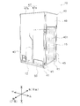
- FIG. 2 is a perspective view of the outdoor unit 10 as viewed from the front side.
- FIG. 3 is a perspective view of the outdoor unit 10 as viewed from the rear side.
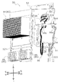
- FIG. 4 is a schematic exploded view of the outdoor unit 10.
- Outdoor unit casing 40 The outdoor unit 10 has an outdoor unit casing 40 which constitutes an outer shell and accommodates the respective devices (11, 12, 13, 14, 15, 16, 20, etc.).
- the outdoor unit casing 40 (corresponding to the “casing” recited in the claims) is formed in a substantially rectangular parallelepiped shape by assembling a plurality of sheet metal members. Most of the left side surface, the right side surface, and the back surface of the outdoor unit casing 40 are openings, and the opening functions as an intake port 401 for sucking the outdoor air flow AF.
- the outdoor unit casing 40 mainly includes a pair of mounting legs 41, a bottom frame 43, a plurality of (here, four) columns 45, a front panel 47, and a fan module 49.
- the mounting leg 41 is a sheet metal member that extends in the left-right direction and supports the bottom frame 43 from below.
- a mounting leg 41 is disposed near the front end and near the rear end.
- the bottom frame 43 is a sheet metal member that constitutes the bottom of the outdoor unit casing 40.
- the bottom frame 43 is disposed on the pair of mounting legs 41.
- the bottom frame 43 has a substantially rectangular shape in plan view.
- the columns 45 extend vertically from the corner portions of the bottom frame 43.
- the pillars 45 extend vertically from each of the four corner portions of the bottom frame 43.
- the front panel 47 is a sheet metal member that constitutes a front portion of the outdoor unit casing 40. More specifically, the front panel 47 includes a first front panel 47a and a second front panel 47b. The first front panel 47 a constitutes a front left portion of the outdoor unit casing 40. The second front panel 47 b constitutes a front right side portion of the outdoor unit casing 40. The first front panel 47 a and the second front panel 47 b are individually fixed to the support 45 by being fastened with screws after being positioned in the outdoor unit casing 40.
- the fan modules 49 are attached near the upper ends of the columns 45.
- the fan module 49 constitutes a portion of the front, rear, left and right sides of the outdoor unit casing 40 above the columns 45 and a top surface of the outdoor unit casing 40.
- the fan module 49 includes the outdoor fan 18 and a bell mouth 491 (see FIG. 7). More specifically, the fan module 49 is an assembly in which the outdoor fan 18 and the bell mouth 491 are accommodated in a substantially rectangular box-like body whose upper and lower surfaces are open.
- the outdoor fan 18 is disposed in a posture in which the rotation axis extends in the vertical direction.
- the upper surface portion of the fan module 49 is open and functions as an outlet 402 for blowing the outdoor air flow AF from the outdoor unit casing 40.
- the outlet 402 is provided with a grid-like grill 492.
- FIG. 2-4 shows an example in which the outdoor unit 10 has one fan module 49
- the outdoor unit 10 may have a plurality of fan modules 49.
- two fan modules 49 may be provided as in the outdoor unit 10 'shown in FIG. 5.
- two fan modules 49 are shown arranged side by side.
- the outdoor unit 10 ' has an outdoor unit casing 40' having a size larger than that of the outdoor unit 10 having one fan module 49, and has a front panel 47 one on each side.
- illustration is omitted, in outdoor unit 10 ', the size of outdoor heat exchanger 15 is larger than outdoor unit 10 according to the size of outdoor unit casing 40'.
- FIG. 6 is a view schematically showing the arrangement of equipment arranged on the bottom frame 43 and the flow direction of the outdoor air flow AF. As shown in FIG. 6, on the bottom frame 43, various devices including the accumulator 11, the compressor 12, the oil separator 13, and the outdoor heat exchanger 15 are disposed at predetermined positions. Further, on the bottom frame 43, an electrical component box 50 for housing the outdoor unit control unit 20 is disposed.
- the outdoor heat exchanger 15 has a heat exchange surface 151 (see FIG. 4) disposed along the left side surface, the right side surface, and the back surface of the outdoor unit casing 40.
- the heat exchange surface 151 has substantially the same height as the intake port 401.
- Most of the back surface, the left side surface, and the right side surface of the outdoor unit casing 40 are the intake port 401, and the heat exchange surface 151 of the outdoor heat exchanger 15 is exposed from the intake port 401.
- the back surface, the left side surface and the right side surface of the outdoor unit casing 40 are substantially formed by the heat exchange surface 151 of the outdoor heat exchanger 15.
- the outdoor heat exchanger 15 has three heat exchange surfaces 151, and in relation to this, it has curved portions on the left and right in a plan view and exhibits a substantially U shape (opened in the front direction) There is.
- the accumulator 11 is disposed on the right front of the compressor 12 at the left front of the curved portion on the right side of the outdoor heat exchanger 15.
- the compressor 12 is disposed on the left front of the accumulator 11 on the left side of the right end of the outdoor heat exchanger 15.
- the compressor 12 is located on the front right side of the outdoor unit casing 40.
- the compressor 12 is located below the fan module 49 (outdoor fan 18). In other words, the outdoor fan 18 is disposed at a height position higher than that of the compressor 12.
- the oil separator 13 is disposed on the left side of the accumulator 11.
- the electrical component box 50 (corresponding to an “electrical component box” recited in the claims) is disposed on the right side of the left end of the outdoor heat exchanger 15 on the left side of the compressor 12 (FIGS. 2 and 4) See -6).
- the electrical component box 50 is located on the front left side of the outdoor unit casing 40.
- FIG. 7 is an enlarged view of the front side of the outdoor unit 10 with the first front panel 47a removed. As shown in FIG. 7, the electrical component box 50 is exposed to the front side when the first front panel 47 a is removed. Thus, the electrical component box 50 can be accessed simply by removing the first front panel 47a without removing the second front panel 47b.
- the electrical component box 50 has a front cover 51 that constitutes a front portion. Details of the electrical component box 50 will be described later.
- FIG. 8 is a view schematically showing the flow of the outdoor air flow AF in the outdoor unit casing 40.
- the outdoor air flow AF flows into the outdoor unit casing 40 from the air inlet 401 formed on the left side, right side and back of the outdoor unit casing 40, and the outdoor heat exchanger After passing through the heat exchange surface 151 (heat exchange surface 151), the air flows mainly from the lower side to the upper side and flows out from the air outlet 402. That is, the outdoor air flow AF flows in the horizontal direction into the outdoor unit casing 40 via the air inlet 401, passes through the outdoor heat exchanger 15, and then turns upward to the air outlet 402. It flows from the bottom to the top.
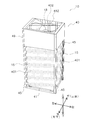
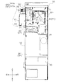
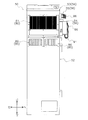
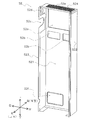
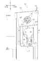
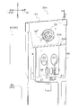
- FIG. 9 is a front view of the electric component box 50 (with the front cover 51 removed).
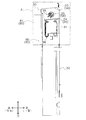
- FIG. 10 is a rear view of the electrical component box 50 shown in FIG.
- FIG. 11 is a right side view of the electrical component box 50 shown in FIG.
- the electrical component box 50 has a width direction (here, left and right direction) and a depth direction (here, front and rear direction) It is a substantially rectangular metal box made of metal having a larger dimension in the height direction (vertical direction) than the dimension.
- Various electric components E1 including light electric components 90 and high electric components 95 described later
- constituting the outdoor unit control unit 20 are accommodated in a space in the electric component box 50 (hereinafter referred to as "internal space SP"). There is.
- the internal space SP includes a lower space SP1 and an upper space SP2 located above the lower space SP1.
- the lower space SP1 and the upper space SP2 communicate without being divided, and there is no clear boundary between them.
- the lower space SP1 is a space that occupies a predetermined height dimension (approximately two thirds of the height dimension of the internal space SP) from the lower end (bottom surface portion of the electrical component box 50) of the internal space SP.
- the electric component E1 such as the terminal block 60 and the reactor 61 is disposed.
- the upper space SP2 is a space occupying from the upper end of the lower space SP1 to the upper end of the internal space SP (the top surface portion of the electrical component box 50).
- a vertical plate 501 that divides the upper space SP2 into two spaces in the depth direction (front and back) is disposed.
- the vertical plate 501 is a sheet metal extending in the vertical direction.
- the vertical plate 501 divides the upper space SP2 into a front upper space SP2a and a rear upper space SP2b located on the back side of the front upper space SP2a.
- the front upper space SP2a and the rear upper space SP2b are arranged in the depth direction of the electric component box 50.
- control boards 71 In the front upper space SP2a, a plurality (two in this case) of control boards 71 (claims in the claims) on which electric components E1 such as a microcomputer including a CPU, various memories, etc. and a communication module are mounted. Equivalent) is housed.
- Each control board 71 is fixed to the front surface portion of the vertical plate 501.
- Each control board 71 is fixed in a posture in which the main surface faces in the front direction (that is, a posture in which the thickness direction extends in the front-rear direction).
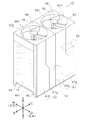
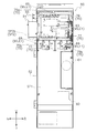
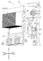
- FIG. 12 is a front view of the electrical component box 50 with the vertical plate 501 (control board 71) removed (the low voltage wiring and high voltage wiring are partially omitted in FIG. 12).
- FIG. 13 is a front perspective view of the electrical component box 50 shown in FIG.
- the rear upper space SP2b accommodates a substrate unit 75 (corresponding to a "substrate” recited in the claims) on which various electrical components E1 for controlling the drive state of the actuator disposed in the outdoor unit 10 are mounted. It is done.
- the board unit 75 includes an electric component mounting portion 75a for controlling a compressor on which an electric component E1 (hereinafter, referred to as “electric component 63 for controlling a compressor”) for inverter controlling the compressor 12 is mounted.
- a fan control electrical component mounting portion 75b on which an electrical component E1 (hereinafter, referred to as "fan control electrical component 66") for controlling a driving state of the fan 18 is mounted.
- the compressor control electrical component 63 is mounted on a compressor control board 76 which is a part of the board unit 75. That is, in the present embodiment, the compressor control electrical component mounting portion 75 a is disposed on the compressor control board 76. Further, the fan control electrical component 66 is mounted on a fan control board 77 which is a part of the board unit 75. That is, in the present embodiment, the fan control electrical component mounting portion 75 b is disposed on the fan control board 77.
- the compressor control electrical component 63 is, for example, a smoothing capacitor or a diode bridge mounted on the front main surface of the compressor control board 76.
- the compressor control electrical component 63 includes various electrical components E1 (for example, power devices including switching elements such as IGBTs) that constitute an inverter. More specifically, in the compressor control board 76 (electric component mounting portion 75a for compressor control), a power module 65 in which a plurality of (six) power devices are integrally formed is mounted.
- the power module 65 is mounted on the rear main surface of the compressor control board 76.
- the power module 65 generates a particularly large amount of heat when energized, as compared with the other electric components E1.
- the power module 65 is, for example, an IPM including a plurality of power devices.
- the power module 65 is disposed at a height higher than the fan control electrical component 66.
- the fan control electrical component 66 is, for example, a switch such as a capacitor, a diode, and a relay.
- a switch such as a capacitor, a diode, and a relay.
- FIGS. 12 and 13 assuming that two outdoor fans 18 are arranged in the outdoor unit 10 (for example, the outdoor unit 10 ′ shown in FIG. 5), the outdoor fans 18 correspond to one-on-one.
- Two fan control boards 77 (fan control electrical component mounting portions 75b) are arranged side by side in the rear upper space SP2b.
- a first cooling unit 80 for cooling the compressor control electrical component 63 (mainly the power module 65) mounted on the compressor control board 76 is provided on the back side of the compressor control board 76. Is located in The first cooling unit 80 is thermally connected to the power module 65 in the installed state.
- the first cooling unit 80 includes a plurality of first cooling unit fins 81 that exchange heat with the outdoor air flow AF. The first cooling unit fins 81 are located on the flow path of the outdoor air flow AF in the installed state.
- a second cooling unit 85 for cooling the fan control electrical component 66 mounted on the fan control board 77 is disposed. More specifically, the second cooling units 85 equal in number (here two) to the fan control boards 77 are disposed in the rear upper space SP2b. The second cooling unit 85 is in one-to-one correspondence with any one of the fan control boards 77 and is disposed on the back side of the corresponding fan control board 77. The second cooling unit 85 is thermally connected to the fan control electrical component 66 in the installed state.
- the second cooling unit 85 has a plurality of second cooling unit fins 86 that exchange heat with the outdoor air flow AF. The second cooling unit fins 86 are located on the flow path of the outdoor air flow AF in the installed state.
- the electric component E1 mounted on the control substrate 71 is referred to as “weak electric component 90” (corresponding to “second electric component” in the claims), and is mounted on the substrate unit 75.
- the electrical component E1 is referred to as a "strong electrical component 95" (corresponding to a "first electrical component” recited in the claims).
- a plurality of electrical wires are drawn into the electrical component box 50.
- a wiring (hereinafter, “weak electrical wiring 91”) that connects the weak electrical component 90 and a device (for example, each outdoor side sensor 19 etc.) corresponding to the weak electrical component 90 Is called).
- a wiring (hereinafter referred to as “a wiring that connects the high electric component 95 and an apparatus corresponding to the high electric component 95 (for example, the compressor 12 or the outdoor fan 18)) (Referred to as a heavy electric wire 96 ").
- the low-voltage wire 91 (corresponding to “second wire” in the claims) is a wire mainly for sending control signals transmitted and received between devices (for example, a sensor or a microcomputer).
- the low voltage wiring 91 is supplied with a voltage (or a current related thereto) between the low voltage component 90 and the corresponding device.
- the heavy electric wire 96 (corresponding to the “first wire” in the claims) is a wire mainly for supplying power to become operation energy of the device (for example, an actuator such as a motor or a heater).
- the heavy electric wire 96 is supplied with a voltage (or a current related thereto) between the high electric component 95 and the corresponding device.
- the values of the voltage and current supplied to the low power wiring 91 are smaller than the values of the voltage and current supplied to the high power wiring 96.
- the values of the voltage and current supplied to the low voltage wiring 91 and the high voltage wiring 96 are appropriately selected according to the design specifications and the installation environment, but here the voltage of 15 V or less is applied to the low voltage wiring 91 (or related thereto Current) is supplied, and the high power wire 96 is supplied with a voltage of 50 V or more (or a current related thereto).
- the electrical component box 50 has a front cover 51 (see FIG. 7) and a main body frame 52 (see FIG. 14-15) as constituent members.
- Front cover 51 is a substantially rectangular plate-like member that constitutes the front portion of the electrical component box 50.
- the front cover 51 has the same width and height as the width and height of the electrical component box 50.
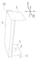
- FIG. 14 is a front perspective view of the main body frame 52.
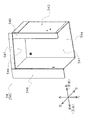
- FIG. 15 is a front perspective view of the main body frame 52 viewed from a direction different from that of FIG.
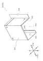
- FIG. 16 is a top view of the electric component box 50 (with the top cover 53 removed).
- the main body frame 52 is a metal casing that constitutes the main body portion of the electrical component box 50.
- the main body frame 52 includes a back surface portion 521 constituting the back surface portion of the electric component box 50, a left side surface portion 522 constituting the left side surface portion of the electric component box 50, and a right surface portion 523 constituting the right side surface portion of the electric component box 50. And a top surface portion 524 that constitutes the top surface portion of the electrical component box 50.
- the back surface portion 521 has a substantially rectangular shape having substantially the same size as the front surface cover 51.
- the left side surface 522 has a substantially rectangular shape, and extends forward from the left end of the back surface 521.
- the right side surface portion 523 has a substantially rectangular shape and extends forward from the right end portion of the back surface portion 521.
- the top surface portion 524 has a substantially rectangular shape, and is connected to upper end portions of the back surface portion 521, the left side surface portion 522, and the right side surface portion 523. Lower end portions of the back surface portion 521, the left side surface portion 522, and the right side surface portion 523 are horizontally bent and extend along the bottom frame 43 so that the main body frame 52 can be inverted on the bottom frame 43 of the outdoor unit casing 40. There is.
- a plurality of holes are formed in the main body frame 52 (rear surface 521). Specifically, the main body frame 52 is formed with a first hole 52a for exposing the radiation fin (the first cooling unit fin 81) included in the first cooling unit 80 to the blowing space S1.
- the first holes 52 a are formed at positions corresponding to the installation positions of the first cooling unit 80 and the compressor control board 76.
- a second hole 52b for exposing the radiation fin (second cooling unit fin 86) included in the second cooling unit 85 to the blowing space S1 is a second cooling unit
- the same number (here two) is formed as 85.
- the second holes 52 b are in one-to-one correspondence with any of the second cooling units 85, and expose the radiation fins included in the corresponding second cooling units 85.
- the second hole 52 b is formed below the first hole 52 a at a position corresponding to the installation position of the corresponding second cooling unit 85 and the fan control board 77.
- a third hole 52c for drawing the low voltage wiring 91 and the high voltage wiring 96 into the electric component box 50 into the electric component box 50 (refer to “wiring in claim (Corresponding to the through hole) is formed.
- the third hole 52c is formed by cutting out a portion of the right side surface portion 523 in a substantially U shape or a substantially C shape at a position corresponding to the upper space SP2.
- the third holes 52c are disposed at a height position lower than the upper end of the substrate unit 75 (more specifically, the compressor control board 76) and at a height position higher than the lower end. The details of the third holes 52c and the lead-in mode of the wiring will be described later.
- a fourth hole 52d for drawing the strong electric wire 96 (particularly, a power line connected to the compressor 12) into the electric component box 50 is formed.
- the fourth hole 52d is formed by punching a part of the right side surface portion 523 in a substantially O-shape above the third hole 52c.
- the strong electric wires 96 drawn into the electric component box 50 through the fourth holes 52 d are three electric wires for supplying a voltage of three phases 200 V to the compressor 12.
- a plurality of fifth holes 52e that function as "exhaust ports” for discharging the air in the electrical component box 50 are formed.
- the fifth hole 52 e is a slit extending in the left-right direction.
- a plurality of fifth holes 52e aligned in the depth direction (front-rear direction) are formed in two rows in the width direction (left-right direction) (see FIG. 16).
- the fifth hole 52e is at a height position lower than the outdoor fan 18, and the radiation fin of the first cooling unit 80 (first cooling unit fin described later 81) It is located at a higher height position.
- Each fifth hole 52e is subjected to burring, and the edge portion (edge portion 52e1) of each fifth hole 52e rises upward (see FIG. 16). Even when the liquid adheres to the upper surface of the top surface 524, the edge 52e1 suppresses the flow of the liquid into the internal space SP via the fifth hole 52e.
- a sixth hole 52f for the serviceman to access the compressor 12 at the time of maintenance or the like is formed in the vicinity of the lower end.
- Cover unit 56 A cover unit 56 (corresponding to a “cover portion” recited in the claims) is disposed on the outer surface of the electrical component box 50 to suppress the infiltration of liquid into the internal space SP.
- the first side cover 54 that suppresses the inflow of liquid from the space 52 c to the inner space SP, and the second side cover 55 that suppresses the inflow of liquid from the fourth hole 52 d to the inner space SP are included.
- FIG. 17 is a perspective view of the top cover 53.
- FIG. FIG. 18 is a perspective view of the top cover 53 as viewed from a direction different from that of FIG.
- the liquid flows into the internal space SP through the fifth hole 52 e formed in the top surface portion 524 of the electrical component box 50.
- the upper end portion of the main body frame 52 is a sheet metal member that covers from above.
- the top cover 53 is spaced above the fifth hole 52e.
- the top cover 53 has an upper cover portion 531, a left side cover portion 532, a right side cover portion 533, and a collar portion 534.
- the upper cover portion 531 is a portion covering the top surface portion 524 (fifth hole 52 e) of the main body frame 52 from above.
- the upper cover portion 531 has a substantially rectangular shape in a plan view, and has a larger area than the top surface portion 524 of the main body frame 52.
- the left side cover portion 532 covers a portion near the upper end of the left side surface portion 522 of the main body frame 52 from the outside.
- the left side cover portion 532 is a portion extending downward from the left end portion of the upper cover portion 531.
- the right side cover portion 533 covers a portion near the upper end of the right side surface portion 523 of the main body frame 52 from the outside.
- the right side cover portion 533 is a portion extending downward from the right end portion of the upper cover portion 531.
- the right side cover portion 533 is formed with an opening 53a at a position overlapping the fourth hole 52d.
- the flange portion 534 is a plate-like portion extending continuously from the lower end portion of the right side cover portion 533 toward the right direction.
- the flange portion 534 is located above the third hole 52 c and the first side cover 54, and covers the periphery of the third hole 52 c and the first side cover 54 from above along with the right side cover portion 533.
- the collar portion 534 covers the contact portion between the first side cover 54 and the electric component box 50 (right side portion 523) together with the right side cover portion 533 from above. Thereby, even if a gap is formed between the first side surface cover 54 and the electrical component box 50 (right side surface 523), the liquid may infiltrate the electrical component box 50 through the gap. Be suppressed.
- the ridge portion 534 is inclined along the inclination angle of the upper portion 544 of the first side cover 54 so as to form a downward slope toward the rear.
- FIG. 19 is a perspective view of the first side cover 54.
- FIG. FIG. 20 is a perspective view of the first side cover 54 viewed from a direction different from that of FIG.
- FIG. 21 is a perspective view of the first side cover 54 as viewed from the right.
- FIG. 22 is a perspective view of the first side cover 54 as viewed from the left.
- the liquid flows into the internal space SP through the third hole 52 c formed in the right side surface 523 of the main body frame 52.
- the sheet metal member is disposed around (above and to the side of) the third hole 52c and covers the third hole 52c from the outside (from the above and from the side).
- the first side cover 54 has a right side 541, a front side 542, a rear side 543, an upper portion 544, a rear side bending portion 545, a front side bending portion 546, and an upper side bending portion 547. ing.
- the right side portion 541 is a portion covering the third hole 52c from the right side.
- the right side portion 541 has a substantially rectangular shape.
- the front side portion 542 is a portion that covers the third hole 52c from the front.
- the front side 542 has a substantially rectangular shape.
- the rear side 543 is a portion that covers the third hole 52c from the rear.
- the rear side 543 has a substantially rectangular shape.
- the upper portion 544 is a portion covering the third hole 52c from above.
- the upper portion 544 has a substantially rectangular shape.
- the rear bent portion 545 is a substantially rectangular portion in which the left end portion of the rear side portion 543 is bent at a substantially right angle.
- the rear bent portion 545 extends from the left end of the rear side 543 in the front direction.
- the rear bent portion 545 contacts the outer surface of the right side surface portion 523 of the electric component box 50 on the left main surface in the installed state.
- the rear bent portion 545 has a seal member 57 (see FIG. 25) attached on the left side surface to prevent a gap from being formed between the rear side bent portion 545 and the right side surface portion 523 of the electric component box 50 in the installed state. Will be attached.
- the front bending portion 546 is a substantially rectangular portion obtained by bending the left end of the front portion 542 at a substantially right angle.
- the front bending portion 546 extends from the left end of the front portion 542 in the front direction.
- the front bending portion 546 abuts on the outer surface of the right side surface portion 523 of the electric component box 50 on the left main surface in the installed state.
- the sealing member 58 (see FIG. 25) is attached on the left surface.
- the upper bending portion 547 is a substantially rectangular portion obtained by bending the left end portion of the upper portion 544 substantially at a right angle.
- the upper bent portion 547 extends upward from the left end of the upper portion 544.
- the upper bent portion 547 abuts the inner surface of the right side surface portion 523 of the electric component box 50 on the main surface on the right side in the installed state. That is, the upper bending portion 547 is located in the electric component box 50 (internal space SP) in the installed state.
- the upper bent portion 547 is attached with a seal member (not shown) on the right side surface in order to prevent a gap from being formed between the upper side bent portion 547 and the right side surface portion 523 of the electric component box 50.
- the first side cover 54 is open at the bottom thereof. That is, the first side cover 54 is formed with an open portion 54 a that opens downward.
- the open portion 54a functions as a "lower opening” for passing the electrical wiring (the weak electrical interconnection 91 and the strong electrical interconnection 96) drawn into the internal space SP through the third hole 52c. That is, the weak electric wire 91 and the strong electric wire 96 are drawn into the first side cover 54 and the inner space SP via the open portion 54a.
- the first side cover 54 is inserted into the third hole 52c in a posture in which the upper bent portion 547 abuts against the inner surface side of the upper edge of the third hole 52c via the seal member, and then the back side bent portion 545 and The front bent portion 546 is screwed and fixed to the right side surface portion 523 of the main body frame 52 so as to be located outside the front end and the rear end of the third hole 52c.
- FIG. 23 is an enlarged view of a portion A of FIG. FIG. 23 shows that the upper portion 544 is inclined at an angle corresponding to the angle ⁇ 1 with respect to the horizontal line h1 in the installed state of the first side cover 54.
- the angle ⁇ 1 can be set appropriately according to the design specification and the installation environment, but is set to 15 degrees here.
- Second side cover 55 The second side surface cover 55 prevents the liquid from flowing into the internal space SP through the fourth hole 52d formed in the right side surface portion 523 of the main body frame 52, from the outside of the fourth hole 52d of the main body frame 52. Cover (from above and from the side).
- the second side cover 55 is a commonly used general-purpose product.
- the second side cover 55 is formed with a plurality of openings (three in this case) for passing power lines (high electric wires 96) connected to the compressor 12.
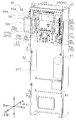
- FIG. 24 is a perspective view of the state shown in FIG. 23 as viewed from the back side.
- FIG. 25 is a view in which the first side cover 54 is omitted in the state shown in FIG.
- FIG. 26 is a perspective view of the state shown in FIG. 25 as viewed from the rear side.
- FIG. 23-26 a state is shown in which the weak electric wire 91 and the strong electric wire 96 are drawn into the electric component box 50 through the third hole 52c, and the strong electric wire 96 is drawn through the fourth hole 52d. There is.
- the weak electrical wire 91 drawn into the electrical component box 50 is a weak electrical wire group in which a large number of weak electrical wires 91 are bundled.
- the number of strong electric wires 96 drawn into the electric component box 50 through the third holes 52c is a large number (here, 36), and is bundled by a binding band or the like. That is, the high power wiring 96 drawn into the electric component box 50 is a high power wiring group in which a large number of high power wirings 96 are bundled.
- the low voltage wiring 91 is close to the high voltage wiring 96 by a predetermined distance (for example, 3 cm) or more, noise is likely to occur.
- a predetermined distance for example, 3 cm
- the low electric wire 91 and the high electric wire 96 are separately drawn separately into the third hole 52c, and both have reliability regarding noise. Secured distance apart.
- a plurality of members are disposed in order to promote the attraction of the low voltage wiring 91 and the high voltage wiring 96 in such a manner.
- a partition 98 for suppressing the proximity of the low voltage wiring 91 and the high voltage wiring 96 drawn into the third hole 52c is disposed in the electrical component box 50 (right side surface 523).
- the partition portion 98 has a partition plate 981 whose thickness direction is the front-rear direction and which extends along the vertical direction and the left-right direction.
- the partition part 98 partitions the low electric wire 91 and the high electric wire 96 by the partition plate 981 concerned, and prevents both from approaching.
- first clamp 99a for bundling a plurality of weak electrical wires 91 and fixing them at a distance from the heavy electrical wires 96 and the second clamp 99b for bundling and fixing a plurality of heavy electrical wires 96 are the right side portion of the first side cover 54. It is arranged in the front and back in the vicinity of the upper end of 541.
- the third hole 52c is conceptually, as shown in FIGS. 25 and 26, a strong electric wire through hole H1 for drawing in the strong electric wire 96 (corresponding to the "first opening” recited in the claims). It can be interpreted that the weak electric wire through hole H2 (corresponding to the “second opening” recited in the claims) for drawing the weak electric wire 91 is continuously configured.
- FIG. 25 and FIG. 26 it is shown that the strong electric wiring through hole H1 and the low electric wiring through hole H2 are adjacent to each other in the front and rear with the two-dotted chain line D1 interposed therebetween.
- the electrical component box 50 is formed with two openings (a high electric wire through hole H1 and a low electric wire through hole H2) on the side. That is, the third hole 52c can be interpreted as a "wiring through hole” formed by combining two openings (the high electric wiring through hole H1 and the low electric wiring through hole H2). That is, in the present embodiment, the third hole 52c doubles as both the strong electric wire through hole H1 and the weak electric wire through hole H2.
- the first side surface cover 54 is disposed in common to the high electric wiring through hole H1 and the low electric wiring through hole H2, and the cost is suppressed in relation to this.
- Characteristics (7-1) Conventionally, in an outdoor unit of a refrigeration apparatus, a compressor is generally disposed on a bottom plate of a casing, and electrical components for supplying power to the compressor are generally accommodated in an electrical component box disposed in the casing. In order to reduce costs, reduce noise, or facilitate wiring management, the dimensions in the longitudinal direction are shortened with regard to the electrical wiring (power supply line) connecting the compressor and the electric component that supplies power to the compressor. In some cases, the wiring is drawn from the side to an electrical component box that accommodates such electrical components.
- the wiring (high power wiring) for supplying power serving as a power source of the device (for example, an actuator or heater such as a compressor) and the device (for example a sensor or microcomputer) Wiring (weak electrical wiring) for sending control signals transmitted / received between them) exists, and there is concern that noise may occur in the weak electrical wiring when the weak electrical wiring and the heavy electrical wiring are close to each other. For this reason, in order to suppress the reduction in reliability, it is usual that the low voltage wiring and the high voltage wiring are separately drawn into the electric component box.
- the cover unit 56 for suppressing the infiltration of the liquid into the electrical component box 50 has a strong electric wire through hole H1 for pulling in the strong electrical wiring 96 on the outer surface of the electrical component box 50. It is disposed around the low electric wiring through hole H2 for drawing in the wiring 91, and covers the upper side and the side of both the high electric wiring through hole H1 and the low electric wiring through hole H2.
- a cover unit in which the high power wiring through hole H1 for pulling the high power wiring 96 and the low power wiring through hole H2 for the low power wiring 91 are common while the high power wiring 96 and the low power wiring 91 are divided and drawn into the electrical component box 50.
- Covering with 56 makes it possible to easily and accurately suppress the infiltration of the liquid into the electrical component box 50 while reducing the number of parts. Therefore, in order to prevent the infiltration of the liquid into the inside of the electrical component box 50 while suppressing the decrease in reliability, the increase in cost is suppressed.
- the outdoor unit casing 40 is formed with the outlet 402 for blowing out the outdoor air flow AF upward, and the outdoor fan 18 is disposed from below in the outdoor unit casing 40.
- An outdoor air flow AF flowing upward and flowing out of the air outlet 402 is generated.
- the outlet 402 for blowing out the outdoor air flow AF is thus formed in the upward direction (that is, there is a particular concern that the liquid may enter the outdoor unit casing 40 via the outlet 402). Also in the above, the entry of the liquid into the electrical component box 50 is suppressed while the cost is suppressed.
- the partition portion 98 is disposed in the electrical component box 50 or the cover unit 56, and the partition portion 98 is a strong electric wire drawn into the strong electric wire through hole H1 and the low electric wire through hole H2.
- 96 and the low voltage wiring 91 are partitioned.
- the strong electric wires 96 drawn into the strong electric wire through holes H1 and the weak electric wires 91 drawn into the weak electric wire through holes H2 are prevented from coming close to each other.
- the generation of noise due to proximity to the high voltage wiring 96 is suppressed.
- the high power wiring through hole H1 and the low power wiring through hole H2 are disposed at a height position lower than the upper end of the substrate unit 75 and higher than the lower end. In relation to this, the high electric wiring through hole H1 and the low electric wiring through hole H2 are disposed close to each other. As a result, the cover unit 56 easily covers both the high electric wiring through hole H1 and the low electric wiring through hole H2, thereby promoting cost reduction.
- the high power wiring 96 and the low power wiring 91 are separated through the third hole 52c (wiring through hole) serving as both the high power wiring through hole H1 and the low power wiring through hole H2. It has been drawn into the item box 50. As a result, both the lead-in portions of the high-power lines 96 and the low-power lines 91 can be easily covered by the common cover unit 56, and cost reduction is promoted.
- the number of strong electric wires 96 drawn into the strong electric wire through holes H1 is 15 or more
- the number of weak electric wires 91 drawn into the weak electric wire through holes H2 is 15 or more.
- the first side cover 54 (cover unit 56) is provided with a "lower opening” (open portion 54a) opened downward, and the strong electric wire 96 and the weak electric wire 91 are , And is drawn into the first side cover 54 and the electrical component box 50 through the “lower opening”.
- a "lower opening” open portion 54a
- the strong electric wire 96 and the weak electric wire 91 are , And is drawn into the first side cover 54 and the electrical component box 50 through the “lower opening”.
- the cover unit 56 includes the first side cover 54 and the top cover 53, and the top cover 53 (the collar portion 534) is positioned above the first side cover 54.
- the side cover 54 is covered from above. Thereby, the entry of the liquid into the electrical component box 50 is more reliably suppressed.
- the high power wiring through hole H1 and the low power wiring through hole H2 may be separately formed so as to be clearly separated. Even in such a case, as long as the heavy electric wire through hole H1 and the low electric wire through hole H2 are covered from the outside on the upper side and the side by the common cover unit 56, the same function and effect as the above embodiment can be realized.
- the strong electric wire through holes H1 and the low electric wire through holes H2 do not necessarily have to be aligned along the horizontal direction, and may be aligned along the vertical direction. In such a case, by enlarging the dimension in the height direction of the first side cover 54, the upper side and the side of both the high electric wiring through hole H1 and the low electric wiring through hole H2 are covered from the outside with one first side cover 54. You may do so.
- the partitioning portion 98 has a partitioning plate 981 in which the thickness direction is the front-rear direction and extends along the vertical direction and the left-right direction, and partitioning between the low voltage wiring 91 and the high voltage wiring 96 And, it was suppressing that both sides approach.
- the configuration of the partitioning portion 98 is not particularly limited as long as it is possible to keep the distance between the weak electrical interconnection 91 and the strong electrical interconnection 96 drawn into the third hole 52c low enough that noise does not easily occur in the weak electrical interconnection 91. .
- a portion “98” that functions as a “partition” at the edge of the third hole 52c by the formation aspect of the third hole 52c formed in the main body frame 52. '' May be provided.
- the main body frame 52 is punched out so as to be partially left at the central portion of the third hole 52c, so that a partition 98 'is provided between the high electric wiring through hole H1 and the low electric wiring through hole H2.
- a state where the third hole 52c is formed is shown.
- the partition portion is formed as shown in FIG. 28, the strong electric wire through hole H1 and the weak electric wire through hole H2 are partially divided in the third hole 52c although they are in communication.
- Example 3 The said embodiment demonstrated the case where the partition part 98 which divides the weak electric wire 91 and the strong electric wire 96 drawn in to the 3rd hole 52c is arrange
- the partitioning portion 98 does not necessarily have to be disposed in the electrical component box 50.
- the partition 98 may be disposed inside the first side cover 54.
- the dividing section 98 is not necessarily required. Omission is possible.
- the high electric wiring through hole H1 and the low electric wiring through hole H2 are disposed at a height lower than the upper end of the substrate unit 75 and higher than the lower end. From this point of view, according to the above aspect, the strong electric wiring through hole H1 and the low electric wiring through hole H2 are disposed close to each other so that the cover unit 56 easily covers both the high electric wiring through hole H1 and the low electric wiring through hole H2. It is preferable that the high power wiring through hole H1 and the low power wiring through hole H2 be disposed.
- the high power wiring through hole H1 and the low power wiring through hole H2 are covered from the outside and above with the common cover unit 56, the high power wiring through hole H1 and the low power wiring through hole H2 are disposed in such a manner. It does not have to be done. That is, the strong electric wiring through hole H1 and the low electric wiring through hole H2 may be disposed at a height position higher than the upper end of the substrate unit 75, as long as no contradiction occurs in the adoption effect described in (7-1) above. , And may be disposed at a height position lower than the lower end of the substrate unit 75.
- the high electric wire 96 extending from the compressor 12 is independently drawn into the electrical component box 50 through the opening (the fourth hole 52 d) different from the other high electric wires 96.
- the present invention is not necessarily limited thereto, and the strong electric wire 96 extending from the compressor 12 is also drawn into the electric component box 50 through the third hole 52c (high electric wire through hole H1) together with the other high electric wire 96. You may do so.
- the low voltage component 90 and the high voltage component 95 are mounted on different substrates.
- the present invention is not necessarily limited thereto, and the low voltage component 90 and the high voltage component 95 may be mounted on the same substrate as long as the reliability is ensured.
- the low-power components 90 mounted on the control board 71 may be mounted on the compressor control board 76 or the fan control board 77.
- the flange portion 534 located above the first side surface cover 54 and suppressing the liquid infiltration into the internal space SP via the third hole 52 c is provided as a part of the top surface cover 53.
- the flange portion 534 is not necessarily included in the top cover 53, and may be provided in another member or may be provided as an independent member.
- the second side cover 55 for suppressing the liquid infiltration from the fourth hole 52d is disposed.
- the second side cover 55 may be omitted as appropriate if it is not necessarily required from the viewpoint of reliability.
- both the third hole 52 c and the fourth hole 52 d can be obtained with only one first side cover 54.
- the upper side and the lateral side of the may be covered from the outside.
- the top cover 53 is disposed above the electrical component box 50 to suppress the infiltration of liquid into the electrical component box 50 mainly through the third hole 52c and the fifth hole 52e. From this point of view, according to the viewpoint of more reliably suppressing the infiltration of the liquid into the electric component box 50 through the third hole 52c and the fifth hole 52e, the top cover 53 is configured in the aspect in the above embodiment. It is preferred to be arranged. However, the top cover 53 is not necessarily required as long as the reliability with respect to the infiltration of the liquid into the electric component box 50 is secured, and the top cover 53 may be omitted as appropriate.
- the outdoor unit 10 has the air outlet 402 formed on the top surface, and the outdoor air flow AF mainly flows from the lower side to the upper side in the outdoor unit casing 40 and is blown upward from the air outlet 402 It is a so-called upper blowing type outdoor unit configured to However, it is not necessarily limited to this, and the outdoor unit 10 may adopt other types.
- the outdoor unit 10 may be a so-called side-blowing type outdoor unit in which the outlet 402 is formed in the front portion and the outdoor air flow AF is blown out from the outlet 402 in the horizontal direction.
- the outdoor fan 18 may be installed in such a posture that the generated outdoor air flow AF mainly flows in the horizontal direction in the outdoor unit casing 40 (the posture in which the rotation axis extends in the horizontal direction). .
- the substrate unit 75 includes the compressor control substrate 76 and the fan control substrate 77, and the compressor control electrical component mounting portion 75a is disposed on the compressor control substrate 76 and the fan control electrical component mounting portion 75b.
- the compressor control electrical component 63 is mounted on the compressor control board 76
- the fan control electrical component 66 is mounted on the fan control board 77
- the compressor control electrical component 63 and the fan control It was mounted on a substrate different from the electrical component 66.
- the present invention is not necessarily limited thereto, and the compressor control electrical component 63 and the fan control electrical component 66 may be mounted on the same substrate (that is, the compressor control electrical component mounting portion 75a and the fan control electrical component The mounting portion 75b may be disposed on the same substrate). That is, the substrate unit 75 does not necessarily have to have a plurality of substrates.
- the configuration mode of the refrigerant circuit RC in the above embodiment is not necessarily limited to the mode shown in FIG. 1, and can be appropriately changed according to the design specification and the installation environment.
- the accumulator 11 and the outdoor expansion valve 16 can be appropriately omitted.
- a device for example, a receiver or the like may be newly added to the refrigerant circuit RC.
- Example 16 The present invention has been applied to the air conditioning system 100 in the above embodiment. However, the present invention is not limited to this, and the present invention is also applicable to other refrigeration systems having a refrigerant circuit (for example, a water heater, a heat pump chiller, etc.).
- a refrigerant circuit for example, a water heater, a heat pump chiller, etc.
- the present invention can be indoors in the outdoor unit of the refrigeration system.
Abstract
Provided is an outdoor unit for a refrigeration device in which reductions in reliability and increases in cost are suppressed. This outdoor unit (10) comprises an outdoor unit casing (40), electrical components (E1) including a strong electrical component (95) and a weak electrical component (90), an electrical component box (50) disposed within the outdoor unit casing (40), a strong electrical wiring (96) by which a voltage or a current is supplied between the strong electrical component (95) and a corresponding device, a weak electrical wiring (91) by which a voltage or a current having a lower value than that in the strong electrical wiring is supplied between the weak electrical component (90) and a corresponding device, and a cover unit (56) that suppresses the infiltration of fluids into the electrical component box (50). A strong electrical wiring through-hole (H1) for leading in the strong electrical wiring (96) and a weak electrical wiring through-hole (H2) for leading in the weak electrical wiring (91) are formed in a side section of the electrical component box (50). The cover unit (56) (first side-surface cover (54)) is disposed in the vicinity of the strong electrical wiring through-hole (H1) and the weak electrical wiring through-hole (H2) in the outer surface of the electrical component box (50) and covers both an upper section and the side section.
Description
本発明は、冷凍装置の室外ユニットに関する。
The present invention relates to an outdoor unit of a refrigeration system.
従来、冷凍装置の室外ユニットでは、圧縮機がケーシングの底板上に配置され、圧縮機に電力供給を行う電気部品についてはケーシング内に配置される電気部品ボックスに収容されるのが一般的である。ここで、圧縮機に電力供給を行う電気部品と圧縮機間を結ぶ電気配線(電力供給線)に関して、長手方向の寸法を短くしてコスト抑制、ノイズ抑制又は配線取り回しの容易化を図るために、係る電気部品を収容する電気品ボックスへその側部から配線を引き込むことが考えられる。例えば、特許文献1(特開2008-144982号公報)では、圧縮機がケーシングの底板上に配置される冷凍装置の室外ユニットにおいて、電力供給線が電気部品ボックスの側部から電気部品ボックス内に引き込まれている。
Conventionally, in an outdoor unit of a refrigeration apparatus, a compressor is generally disposed on a bottom plate of a casing, and electrical components for supplying power to the compressor are generally accommodated in an electrical component box disposed in the casing. . Here, with regard to the electric wiring (electric power supply line) connecting the electric component for supplying electric power to the compressor and the electric compressor, the dimension in the longitudinal direction is shortened to reduce costs, suppress noise, or facilitate wiring management. It is conceivable to pull the wiring from the side into an electrical item box that accommodates such electrical components. For example, in Patent Document 1 (Japanese Patent Laid-Open No. 2008-144982), in an outdoor unit of a refrigeration apparatus in which a compressor is disposed on a bottom plate of a casing, a power supply line is inserted from the side portion of the electric component box into the electric component box I'm drawn.
ここで、電気部品ボックスに引き込まれる電気配線については、機器(例えば圧縮機等のアクチュエータやヒータ)の動力源となる電力供給を行うための配線(強電配線)と、機器(例えばセンサやマイクロコンピュータ)間で送受信される制御信号を送るための配線(弱電配線)が存在する。弱電配線は強電配線より値が小さい電圧又は電流を供給されることが一般的であり、弱電配線と強電配線とが近接する場合には弱電配線においてノイズが生じることが懸念される。このため、信頼性低下を抑制するために、弱電配線と強電配線とは分けて電気部品ボックスへ引き込まれるのが通常である。
Here, with regard to the electrical wiring drawn into the electrical component box, a wiring (high-power wiring) for supplying power serving as a power source of a device (for example, an actuator or heater such as a compressor) and a device (for example, a sensor or microcomputer) Wiring (weak electrical wiring) for sending control signals transmitted / received between). In general, a low voltage wiring is supplied with a voltage or current having a smaller value than that of a high voltage wiring, and when the low voltage wiring and the high voltage wiring are close to each other, noise may occur in the low voltage wiring. For this reason, in order to suppress the reduction in reliability, it is usual that the low voltage wiring and the high voltage wiring are separately drawn into the electric component box.
一方で、冷凍装置の室外ユニットでは、電気部品ボックス内への液体の浸入を防止するための対策が必要となるが、強電配線用の配線の引き込み部分、及び弱電配線用の配線の引き込み部分のそれぞれに対して係る対策を個別に行う場合には、コスト増大が懸念される。
On the other hand, in the outdoor unit of the refrigeration system, it is necessary to take measures to prevent the liquid from entering the electric component box, but the lead-in part of the wiring for heavy electric wiring and the lead-in part of the wiring for weak electric wiring When taking measures individually for each, there is a concern that costs will increase.
そこで本発明の課題は、信頼性低下を抑制するとともにコスト増大を抑制する冷凍装置の室外ユニットを提供することである。
Then, the subject of this invention is providing the outdoor unit of the freezing apparatus which suppresses a reliability fall and suppresses a cost increase.
本発明の第1観点に係る冷凍装置の室外ユニットは、ケーシングと、電気部品と、電気部品ボックスと、第1配線と、第2配線と、カバー部と、を備える。ケーシングは、複数の機器を収容する。電気部品は、第1電気部品と、第2電気部品と、を含む。電気部品ボックスは、ケーシング内に配置される。電気部品ボックスは、電気部品を収容する。第1配線は、第1電気部品といずれかの機器との間で、電圧又は電流を供給される。第2配線は、第2電気部品と他のいずれかの機器との間で、第1配線に供給されるよりも小さい値の電圧又は電流を供給される。カバー部は、電気部品ボックス内への液体の浸入を抑制する。電気部品ボックスには、第1開口と、第2開口と、が側方に形成される。第1開口は、第1配線を引き込むための開口である。第2開口は、第2配線を引き込むための開口である。カバー部は、電気部品ボックスの外面において、第1開口及び第2開口の周囲に配置される。カバー部は、第1開口及び第2開口双方の上方及び側方を覆う。
An outdoor unit of a refrigeration apparatus according to a first aspect of the present invention includes a casing, an electrical component, an electrical component box, a first wire, a second wire, and a cover portion. The casing accommodates a plurality of devices. The electrical component includes a first electrical component and a second electrical component. The electrical component box is disposed in the casing. The electrical component box accommodates the electrical components. The first wiring is supplied with voltage or current between the first electrical component and any device. The second wiring is supplied, between the second electrical component and any other device, with a voltage or current of a smaller value than that supplied to the first wiring. The cover portion suppresses the infiltration of the liquid into the electrical component box. A first opening and a second opening are formed laterally in the electrical component box. The first opening is an opening for drawing in the first wiring. The second opening is an opening for drawing in the second wiring. The cover portion is disposed on the outer surface of the electrical component box around the first opening and the second opening. The cover portion covers the upper side and the side of both the first opening and the second opening.
本発明の第1観点に係る冷凍装置の室外ユニットでは、電気部品ボックス内への液体の浸入を抑制するカバー部は、電気部品ボックスの外面において、第1配線を引き込むための第1開口及び第2配線を引き込むための第2開口の周囲に配置され、第1開口及び第2開口双方の上方及び側方を覆う。これにより、第1配線及び第2配線を分けて電気部品ボックスへ引き込みつつ、第1配線引き込み用の第1開口及び第2配線引き込み用の第2開口が共通のカバー部で覆われることで、部品点数が削減されつつ、電気部品ボックス内への液体の浸入を簡易且つ的確に抑制することが可能となる。よって、信頼性低下が抑制されつつ、電気部品ボックス内への液体の浸入を防止するうえでコスト増大が抑制される。
In the outdoor unit of the refrigeration apparatus according to the first aspect of the present invention, the cover portion for suppressing the infiltration of the liquid into the electric component box is a first opening for pulling in the first wiring and an outer surface of the electric component box. (2) It is disposed around the second opening for drawing in wiring, and covers the upper side and the side of both the first opening and the second opening. Thus, the first opening for drawing in the first wiring and the second opening for drawing the second wiring are covered by the common cover portion while the first wiring and the second wiring are divided and drawn into the electric component box. While the number of parts is reduced, it is possible to simply and accurately suppress the infiltration of the liquid into the electric component box. Therefore, the increase in cost is suppressed in preventing the infiltration of the liquid into the electric component box while the decrease in the reliability is suppressed.
なお、ここでの「第1配線」は、主として、機器(例えばモータ等のアクチュエータやヒータ)の動力源となる電力供給を行うための配線(いわゆる強電配線)である。また、「第2配線」は、主として、機器(例えばセンサやマイクロコンピュータ)間で送受信される制御信号を送るための配線(いわゆる弱電配線)であり、第1配線に所定距離(例えば3cm)以内で近接することでノイズが特に生じやすい配線である。「第1配線」及び「第2配線」のそれぞれに供給される電圧及び電流の値は、設計仕様や設置環境に応じて適宜選定される。例えば、「第1配線」には50V以上の電圧(またはそれに関する電流)が供給される。また、例えば「第2配線」には15V以下の電圧(またはそれに関する電流)が供給される。
Here, the “first wiring” is a wiring (so-called high-power wiring) for supplying power, which is a power source of an apparatus (for example, an actuator such as a motor or a heater). The “second wire” is a wire (so-called weak electrical wire) mainly for transmitting a control signal transmitted / received between devices (for example, a sensor or a microcomputer), and within a predetermined distance (for example, 3 cm) to the first wire. Noise is apt to be generated particularly by proximity. The values of the voltage and current supplied to each of the “first wiring” and the “second wiring” are appropriately selected according to the design specification and the installation environment. For example, a voltage (or current related thereto) of 50 V or more is supplied to the “first wiring”. Also, for example, a voltage (or current related thereto) of 15 V or less is supplied to the “second wire”.
また、ここでの「複数の機器」は冷凍装置を構成する機器であり、「複数の機器」には、例えば、圧縮機、ファン、電動弁、電磁弁、ヒータ、温度センサ及び圧力センサのいずれか/全てが含まれる。
Moreover, "a plurality of devices" in this case are devices constituting a refrigeration system, and any of "a plurality of devices" may be, for example, a compressor, a fan, a motorized valve, a solenoid valve, a heater, a temperature sensor, or a pressure sensor. Or all included.
本発明の第2観点に係る冷凍装置の室外ユニットは、第1観点に係る冷凍装置の室外ユニットであって、機器には、ファンが含まれる。ファンは、空気流を生成する。ケーシングには、吹出口が形成される。吹出口は、上方向に空気流を吹き出すための開口である。空気流は、ケーシング内において下方から上方へ向かって流れ吹出口から流出する空気の流れである。
The outdoor unit of the refrigeration apparatus according to the second aspect of the present invention is an outdoor unit of the refrigeration apparatus according to the first aspect, and the apparatus includes a fan. The fan generates an air flow. An outlet is formed in the casing. The outlet is an opening for blowing an air flow upward. The air flow is a flow of air flowing from the lower side to the upper side in the casing and flowing out of the air outlet.
本発明の第2観点に係る冷凍装置の室外ユニットでは、上方向に空気流を吹き出すための吹出口を形成された室外ユニット(すなわち吹出口を介してケーシングへの液体の浸入が特に懸念される室外ユニット)においても、コストが抑制されつつ電気部品ボックスへの液体の浸入が抑制される。
In the outdoor unit of the refrigeration apparatus according to the second aspect of the present invention, the outdoor unit provided with the outlet for blowing out the air flow in the upper direction (i.e., the entry of liquid into the casing through the outlet is particularly concerned Also in the outdoor unit, the entry of the liquid into the electric component box is suppressed while the cost is suppressed.
本発明の第3観点に係る冷凍装置の室外ユニットは、第1観点又は第2観点に係る冷媒冷凍装置の室外ユニットであって、電気部品ボックス又はカバー部には、仕切部が配置される。仕切部は、第1開口及び第2開口に引き込まれる第1配線及び第2配線を仕切る。
An outdoor unit of a refrigeration apparatus according to a third aspect of the present invention is an outdoor unit of a refrigerant refrigeration apparatus according to the first aspect or the second aspect, and a partition part is disposed in the electric component box or the cover part. The partition part partitions the first wiring and the second wiring drawn into the first opening and the second opening.
これにより、第1開口に引き込まれる第1配線、及び第2開口に引き込まれる第2配線に関し、両者が近接することが抑制される。その結果、第2配線において、第1配線に近接することによるノイズの発生が抑制される。よって、信頼性低下がさらに抑制される。
As a result, with respect to the first wiring drawn into the first opening and the second wiring drawn into the second opening, the proximity of both is suppressed. As a result, in the second wiring, generation of noise due to proximity to the first wiring is suppressed. Therefore, the decrease in reliability is further suppressed.
本発明の第4観点に係る冷凍装置の室外ユニットは、第1観点から第3観点のいずれかに係る冷凍装置の室外ユニットであって、基板を備える。基板は、電気部品を実装される。第1開口及び第2開口は、基板の上端よりも低い高さ位置であって下端よりも高い高さ位置に配置される。
The outdoor unit of the refrigeration apparatus according to the fourth aspect of the present invention is an outdoor unit of the refrigeration apparatus according to any one of the first to third aspects, and includes a substrate. The substrate is mounted with electrical components. The first opening and the second opening are disposed at a height position lower than the upper end of the substrate and higher than the lower end.
本発明の第4観点に係る冷凍装置の室外ユニットでは、第1開口及び第2開口は、基板の上端よりも低い高さ位置であって下端よりも高い高さ位置に配置されることで、第1開口及び第2開口が近接配置されうる。その結果、カバー部が第1開口及び第2開口の双方を覆いやすくなり、コスト抑制が促進される。
In the outdoor unit of the refrigeration apparatus according to the fourth aspect of the present invention, the first opening and the second opening are disposed at a height position lower than the upper end of the substrate and higher than the lower end. The first opening and the second opening may be disposed close to each other. As a result, the cover portion easily covers both the first opening and the second opening, which promotes cost reduction.
本発明の第5観点に係る冷凍装置の室外ユニットは、第1観点から第4観点のいずれかに係る冷凍装置の室外ユニットであって、電気部品ボックスには、配線通し穴が形成される。配線通し穴は、第1開口及び第2開口の双方を兼ねる。第1配線及び第2配線は、配線通し穴を介して、分かれて電気部品ボックス内に引き込まれる。カバー部は、配線通し穴の周囲に配置される。カバー部は、配線通し穴の上方及び側方を覆う。
An outdoor unit of a refrigeration apparatus according to a fifth aspect of the present invention is an outdoor unit of the refrigeration apparatus according to any one of the first to fourth aspects, and a wiring through hole is formed in the electric component box. The wiring through hole doubles as both the first opening and the second opening. The first wiring and the second wiring are separated and drawn into the electric component box through the wiring through holes. The cover portion is disposed around the wiring through hole. The cover portion covers the upper side and the side of the wiring through hole.
本発明の第5観点に係る冷凍装置の室外ユニットでは、第1配線及び第2配線は、第1開口及び第2開口の双方を兼ねる配線通し穴を介して、分かれて電気部品ボックス内に引き込まれる。これにより、第1配線及び第2配線の引き込み部分の双方をカバー部によって覆いやすくなり、コスト抑制がさらに促進される。
In the outdoor unit of the refrigeration apparatus according to the fifth aspect of the present invention, the first wiring and the second wiring are separated and drawn into the electric component box through the wiring through hole serving as both the first opening and the second opening. Be As a result, both of the first wiring and the lead-in portion of the second wiring can be easily covered by the cover portion, and cost reduction is further promoted.
本発明の第6観点に係る冷凍装置の室外ユニットは、第1観点から第5観点のいずれかに係る冷凍装置の室外ユニットであって、第1開口に引き込まれる第1配線、及び第2開口に引き込まれる第2配線は、それぞれ15本以上である。
An outdoor unit of a refrigeration apparatus according to a sixth aspect of the present invention is an outdoor unit of the refrigeration apparatus according to any one of the first to fifth aspects, wherein the first wiring drawn into the first opening, and the second opening The number of second wires drawn in is 15 or more.
本発明の第6観点に係る冷凍装置の室外ユニットでは、電気部品ボックス内に引き込まれる電気配線の数が多く、ノイズに因る信頼性低下や、液体浸入抑制に関してコスト増大が特に懸念される場合でも、信頼性低下が抑制されるとともに電気部品ボックス内への液体の浸入を防止するうえでコスト増大が抑制される。
In the outdoor unit of the refrigeration apparatus according to the sixth aspect of the present invention, the number of electric wires drawn into the electric component box is large, and there is a particular concern about cost reduction with regard to reliability degradation due to noise and suppression of liquid intrusion. However, the decrease in reliability is suppressed and the increase in cost is suppressed in preventing the liquid from entering the electric component box.
本発明の第7観点に係る冷凍装置の室外ユニットは、第1観点から第6観点のいずれかに係る冷凍装置の室外ユニットであって、カバー部は、下方に開放する下開口を形成される。第1配線及び第2配線は、下開口を介して、カバー部及び電気部品ボックス内に引き込まれる。これにより、第1開口及び第2開口への液体浸入用のカバー部を簡易に構成することが可能となる。
An outdoor unit of a refrigeration apparatus according to a seventh aspect of the present invention is an outdoor unit of a refrigeration apparatus according to any one of the first to sixth aspects, wherein the cover portion is formed with a lower opening opened downward. . The first wiring and the second wiring are drawn into the cover portion and the electric component box through the lower opening. As a result, it is possible to simply configure the cover portion for liquid penetration to the first opening and the second opening.
本発明の第8観点に係る冷凍装置の室外ユニットは、第1観点から第7観点のいずれかに係る冷凍装置の室外ユニットであって、カバー部は、第1カバー部材と、第2カバー部材と、を含む。第2カバー部材は、第1カバー部材の上方に位置する。第2カバー部材は、第1カバー部材を上方から覆う。これにより、電気部品ボックス内への液体の浸入がさらに抑制される。
An outdoor unit of a refrigeration apparatus according to an eighth aspect of the present invention is an outdoor unit of a refrigeration apparatus according to any one of the first to seventh aspects, wherein the cover portion is a first cover member and a second cover member. And. The second cover member is located above the first cover member. The second cover member covers the first cover member from above. This further suppresses the infiltration of the liquid into the electrical component box.
本発明の第1観点に係る冷凍装置の室外ユニットでは、第1配線及び第2配線を分けて電気部品ボックスへ引き込みつつ、第1配線引き込み用の第1開口及び第2配線引き込み用の第2開口が共通のカバー部で覆われることで、部品点数を削減しつつ、電気部品ボックス内への液体の浸入を簡易且つ的確に抑制することが可能となる。よって、信頼性低下が抑制されつつ、電気部品ボックス内への液体の浸入を防止するうえでコスト増大が抑制される。
In the outdoor unit of the refrigeration apparatus according to the first aspect of the present invention, while the first wiring and the second wiring are divided and drawn into the electric component box, the first opening for drawing the first wiring and the second opening for the second wiring drawing By covering the opening with the common cover portion, it is possible to simply and accurately suppress the infiltration of the liquid into the electric component box while reducing the number of parts. Therefore, the increase in cost is suppressed in preventing the infiltration of the liquid into the electric component box while the decrease in the reliability is suppressed.
本発明の第2観点に係る冷凍装置の室外ユニットでは、上方向に空気流を吹き出すための吹出口を形成された室外ユニット(すなわち吹出口を介してケーシングへの液体の浸入が特に懸念される室外ユニット)においても、コストが抑制されつつ電気部品ボックスへの液体の浸入が抑制される。
In the outdoor unit of the refrigeration apparatus according to the second aspect of the present invention, the outdoor unit provided with the outlet for blowing out the air flow in the upper direction (i.e., the entry of liquid into the casing through the outlet is particularly concerned Also in the outdoor unit, the entry of the liquid into the electric component box is suppressed while the cost is suppressed.
本発明の第3観点に係る冷凍装置の室外ユニットでは、信頼性低下がさらに抑制される。
In the outdoor unit of the refrigeration apparatus according to the third aspect of the present invention, the decrease in reliability is further suppressed.
本発明の第4観点に係る冷凍装置の室外ユニットでは、コスト抑制が促進される。
In the outdoor unit of the refrigeration apparatus according to the fourth aspect of the present invention, cost reduction is promoted.
本発明の第5観点に係る冷凍装置の室外ユニットでは、コスト抑制がさらに促進される。
In the outdoor unit of the refrigeration apparatus according to the fifth aspect of the present invention, cost reduction is further promoted.
本発明の第6観点に係る冷凍装置の室外ユニットでは、電気部品ボックス内に引き込まれる電気配線の数が多く、ノイズに因る信頼性低下や、液体浸入抑制に関してコスト増大が特に懸念される場合でも、信頼性低下が抑制されるとともに電気部品ボックス内への液体の浸入を防止するうえでコスト増大が抑制される。
In the outdoor unit of the refrigeration apparatus according to the sixth aspect of the present invention, the number of electric wires drawn into the electric component box is large, and there is a particular concern about cost reduction with regard to reliability degradation due to noise and suppression of liquid intrusion. However, the decrease in reliability is suppressed and the increase in cost is suppressed in preventing the liquid from entering the electric component box.
本発明の第7観点に係る冷凍装置の室外ユニットでは、第1開口及び第2開口への液体浸入用のカバー部を簡易に構成することが可能となる。
In the outdoor unit of the refrigeration apparatus according to the seventh aspect of the present invention, it is possible to simplify the cover portion for liquid infiltration to the first opening and the second opening.
本発明の第8観点に係る冷凍装置の室外ユニットでは、電気部品ボックス内への液体の浸入がさらに抑制される。
In the outdoor unit of the refrigeration apparatus according to the eighth aspect of the present invention, the entry of liquid into the electrical component box is further suppressed.
以下、図面を参照しながら、本発明の一実施形態に係る室外ユニット10について説明する。なお、以下の実施形態は、本発明の具体例であって、本発明の技術的範囲を限定するものではなく、発明の要旨を逸脱しない範囲で適宜変更が可能である。また、以下の説明において、「上」、「下」、「左」、「右」、「前」、「後」、「前面」、「背面」は、特にことわりのない限り、図2―28に示される方向を意味している(但し、以下の実施例における左右及び/又は前後については適宜反転させてもよい)。
Hereinafter, the outdoor unit 10 which concerns on one Embodiment of this invention is demonstrated, referring drawings. The following embodiments are specific examples of the present invention and do not limit the technical scope of the present invention, and various modifications can be made without departing from the scope of the present invention. Also, in the following description, “upper”, “lower”, “left”, “right”, “front”, “rear”, “front”, and “back” refer to FIG. 2-28 unless otherwise specified. It means that the direction shown in (However, the left and right and / or back and forth in the following embodiments may be reversed as appropriate).
本発明の一実施形態に係る室外ユニット10は、空調システム100(冷凍装置)に適用されている。
An outdoor unit 10 according to an embodiment of the present invention is applied to an air conditioning system 100 (refrigerating apparatus).
(1)空調システム100
図1は、本発明の一実施形態に係る室外ユニット10を有する空調システム100の概略構成図である。空調システム100は、蒸気圧縮式の冷凍サイクルによって、対象空間(居住空間や貯蔵庫内等の被空調空間)の冷却又は加熱等の空調を行うシステムである。空調システム100は、主として、室外ユニット10と、複数(ここでは2台)の室内ユニット30(30a、30b)と、液側連絡配管L1及びガス側連絡配管G1と、を有している。 (1)Air conditioning system 100
FIG. 1 is a schematic configuration diagram of anair conditioning system 100 having an outdoor unit 10 according to an embodiment of the present invention. The air conditioning system 100 is a system that performs air conditioning such as cooling or heating of a target space (air-conditioned space such as a living space or storage) by a vapor compression refrigeration cycle. The air conditioning system 100 mainly includes an outdoor unit 10, a plurality of (two in this case) indoor units 30 (30a, 30b), a liquid side communication pipe L1, and a gas side communication pipe G1.
図1は、本発明の一実施形態に係る室外ユニット10を有する空調システム100の概略構成図である。空調システム100は、蒸気圧縮式の冷凍サイクルによって、対象空間(居住空間や貯蔵庫内等の被空調空間)の冷却又は加熱等の空調を行うシステムである。空調システム100は、主として、室外ユニット10と、複数(ここでは2台)の室内ユニット30(30a、30b)と、液側連絡配管L1及びガス側連絡配管G1と、を有している。 (1)
FIG. 1 is a schematic configuration diagram of an
空調システム100では、室外ユニット10と室内ユニット30とが、液側連絡配管L1及びガス側連絡配管G1を介して接続されることで、冷媒回路RCが構成されている。空調システム100では、冷媒回路RC内において、冷媒が、圧縮され、冷却又は凝縮され、減圧され、加熱又は蒸発された後に、再び圧縮される、という冷凍サイクルが行われる。
In the air conditioning system 100, a refrigerant circuit RC is configured by connecting the outdoor unit 10 and the indoor unit 30 via the liquid side communication pipe L1 and the gas side communication pipe G1. In the air conditioning system 100, in the refrigerant circuit RC, a refrigeration cycle is performed in which the refrigerant is compressed, cooled or condensed, decompressed, heated or evaporated, and then compressed again.
(1-1)室外ユニット10
室外ユニット10は、室外空間に設置される。室外空間は、空気調和が行われる対象空間外の空間であり、例えば建物の屋上等の屋外や、地下空間等である。室外ユニット10は、液側連絡配管L1及びガス側連絡配管G1を介して各室内ユニット30と接続されており、冷媒回路RCの一部(室外側回路RC1)を構成している。室外ユニット10は、室外側回路RC1を構成する機器として、主としてアキュームレータ11、圧縮機12、油分離器13、四路切換弁14、室外熱交換器15、及び室外膨張弁16等を有している。これらの機器(11-16)は、冷媒配管によって接続されている。 (1-1)Outdoor unit 10
Theoutdoor unit 10 is installed in the outdoor space. The outdoor space is a space outside the target space where air conditioning is performed, and is, for example, the outdoors such as the roof of a building, an underground space, or the like. The outdoor unit 10 is connected to each indoor unit 30 via the liquid side communication pipe L1 and the gas side communication pipe G1, and constitutes a part of the refrigerant circuit RC (the outdoor side circuit RC1). The outdoor unit 10 mainly includes an accumulator 11, a compressor 12, an oil separator 13, a four-way switching valve 14, an outdoor heat exchanger 15, an outdoor expansion valve 16 and the like as devices constituting the outdoor circuit RC1. There is. These devices (11-16) are connected by a refrigerant pipe.
室外ユニット10は、室外空間に設置される。室外空間は、空気調和が行われる対象空間外の空間であり、例えば建物の屋上等の屋外や、地下空間等である。室外ユニット10は、液側連絡配管L1及びガス側連絡配管G1を介して各室内ユニット30と接続されており、冷媒回路RCの一部(室外側回路RC1)を構成している。室外ユニット10は、室外側回路RC1を構成する機器として、主としてアキュームレータ11、圧縮機12、油分離器13、四路切換弁14、室外熱交換器15、及び室外膨張弁16等を有している。これらの機器(11-16)は、冷媒配管によって接続されている。 (1-1)
The
アキュームレータ11は、圧縮機12に液冷媒が過度に吸入されることを抑制すべく、冷媒を貯留して気液分離する容器である。
The accumulator 11 is a container that stores refrigerant and separates gas and liquid in order to suppress excessive suction of liquid refrigerant into the compressor 12.
圧縮機12は、冷凍サイクルにおける低圧の冷媒を高圧になるまで圧縮する機器である。本実施形態では、圧縮機12は、ロータリ式やスクロール式等の容積式の圧縮要素が圧縮機モータM12によって回転駆動される密閉式構造を有している。また、ここでは、圧縮機モータM12は、インバータにより運転周波数の制御が可能であり、これにより、圧縮機12の容量制御が可能になっている。圧縮機12の発停並びに運転容量は、室外ユニット制御部20によって制御される。
The compressor 12 is a device for compressing the low pressure refrigerant in the refrigeration cycle to a high pressure. In the present embodiment, the compressor 12 has a closed structure in which a rotary or scroll positive displacement compression element is rotationally driven by the compressor motor M12. Furthermore, here, the compressor motor M12 can control the operating frequency by means of an inverter, whereby capacity control of the compressor 12 is possible. The outdoor unit controller 20 controls the on / off and operating capacity of the compressor 12.
油分離器13は、圧縮機12から吐出される冷媒に相溶した冷凍機油を分離して圧縮機12へ戻す容器である。
The oil separator 13 is a container that separates refrigeration oil compatible with the refrigerant discharged from the compressor 12 and returns it to the compressor 12.
四路切換弁14は、冷媒回路RCにおける冷媒の流れを切り換えるための流路切換弁である。
The four-way switching valve 14 is a flow passage switching valve for switching the flow of the refrigerant in the refrigerant circuit RC.
室外熱交換器15は、冷媒の凝縮器(又は放熱器)又は蒸発器として機能する熱交換器である。
The outdoor heat exchanger 15 is a heat exchanger that functions as a refrigerant condenser (or a radiator) or an evaporator.
室外膨張弁16は、開度制御が可能な電動弁であり、開度に応じて流入する冷媒を減圧する又は流量調節する。
The outdoor expansion valve 16 is a motor-operated valve capable of controlling the opening degree, and decompresses or adjusts the flow rate of the inflowing refrigerant according to the opening degree.
また、室外ユニット10は、室外空気流AFを生成する室外ファン18(特許請求の範囲記載の「ファン」に相当)を有している。室外空気流AF(特許請求の範囲記載の「空気流」に相当)は、室外ユニット10外から室外ユニット10内へ流入して室外熱交換器15を通過する空気の流れである。室外空気流AFは、室外熱交換器15を流れる冷媒の冷却源又は加熱源であり、室外熱交換器15を通過する際に室外熱交換器15内の冷媒と熱交換を行う。室外ファン18は、室外ファンモータM18を含み、室外ファンモータM18に連動して駆動する。室外ファン18の発停及び回転数は、室外ユニット制御部20によって適宜制御される。
The outdoor unit 10 also includes an outdoor fan 18 (corresponding to a "fan" recited in the claims) that generates the outdoor air flow AF. The outdoor air flow AF (corresponding to “air flow” in the claims) is a flow of air flowing from the outside of the outdoor unit 10 into the outdoor unit 10 and passing through the outdoor heat exchanger 15. The outdoor air flow AF is a cooling source or a heating source of the refrigerant flowing through the outdoor heat exchanger 15. When passing through the outdoor heat exchanger 15, the outdoor air flow AF exchanges heat with the refrigerant in the outdoor heat exchanger 15. The outdoor fan 18 includes an outdoor fan motor M18 and is driven in conjunction with the outdoor fan motor M18. The outdoor unit control unit 20 appropriately controls the start / stop and the number of rotations of the outdoor fan 18.
また、室外ユニット10には、冷媒回路RC内の冷媒の状態(主に圧力又は温度)を検出するための複数の室外側センサ19が配置されている。室外側センサ19は、圧力センサや、サーミスタ又は熱電対等の温度センサである。室外側センサ19には、例えば、圧縮機12の吸入側における冷媒の圧力である吸入圧力を検出する吸入圧力センサ、圧縮機12の吐出側における冷媒の圧力である吐出圧力を検出する吐出圧力センサ、及び室外熱交換器15における冷媒の温度を検出する温度センサ等が含まれる。
Further, in the outdoor unit 10, a plurality of outdoor side sensors 19 for detecting the state (mainly pressure or temperature) of the refrigerant in the refrigerant circuit RC are disposed. The outdoor side sensor 19 is a pressure sensor, or a temperature sensor such as a thermistor or a thermocouple. The outdoor side sensor 19 includes, for example, a suction pressure sensor that detects a suction pressure that is the pressure of the refrigerant on the suction side of the compressor 12, and a discharge pressure sensor that detects a discharge pressure that is the pressure of the refrigerant on the discharge side of the compressor 12. , And a temperature sensor for detecting the temperature of the refrigerant in the outdoor heat exchanger 15.
また、室外ユニット10は、室外ユニット10に含まれる各機器の動作・状態を制御する室外ユニット制御部20を有している。室外ユニット制御部20は、CPUやメモリ等を有するマイクロコンピュータや、各種電気部品(例えばコンデンサ、半導体素子及びコイル部品等)を含んでいる。室外ユニット制御部20は、室外ユニット10に含まれる各機器(12、14、16、18等)や室外側センサ19と電気的に接続されており、互いに信号の入出力を行う。また、室外ユニット制御部20は、各室内ユニット30の室内ユニット制御部35やリモコン(図示省略)と制御信号等の送受信を行う。室外ユニット制御部20は、後述の電装品箱50に収容されている。
The outdoor unit 10 also includes an outdoor unit control unit 20 that controls the operation and state of each device included in the outdoor unit 10. The outdoor unit control unit 20 includes a microcomputer having a CPU, a memory, and the like, and various electric components (for example, a capacitor, a semiconductor element, a coil component, and the like). The outdoor unit control unit 20 is electrically connected to the devices (12, 14, 16, 18, etc.) included in the outdoor unit 10 and the outdoor side sensor 19, and performs signal input / output with each other. Further, the outdoor unit control unit 20 transmits and receives control signals and the like to and from the indoor unit control unit 35 of each indoor unit 30 and a remote controller (not shown). The outdoor unit control unit 20 is housed in an electrical component box 50 described later.
室外ユニット10の構造の詳細については、後述する。
Details of the structure of the outdoor unit 10 will be described later.
(1-2)室内ユニット30
室内ユニット30は、室内(居室や天井裏空間等)に設置されており、冷媒回路RCの一部(室内側回路RC2)を構成している。室内ユニット30は、室内側回路RC2を構成する機器として、主として、室内膨張弁31及び室内熱交換器32等を有している。 (1-2)Indoor unit 30
Theindoor unit 30 is installed indoors (a room, a space above the ceiling, etc.), and constitutes a part of the refrigerant circuit RC (the indoor side circuit RC2). The indoor unit 30 mainly includes an indoor expansion valve 31, an indoor heat exchanger 32, and the like as devices constituting the indoor side circuit RC2.
室内ユニット30は、室内(居室や天井裏空間等)に設置されており、冷媒回路RCの一部(室内側回路RC2)を構成している。室内ユニット30は、室内側回路RC2を構成する機器として、主として、室内膨張弁31及び室内熱交換器32等を有している。 (1-2)
The
室内膨張弁31は、開度制御が可能な電動弁であり、開度に応じて流入する冷媒を減圧する又は流量調節する。
The indoor expansion valve 31 is a motor-operated valve capable of controlling the opening degree, and decompresses or adjusts the flow rate of the inflowing refrigerant according to the opening degree.
室内熱交換器32は、冷媒の蒸発器又は凝縮器(又は放熱器)として機能する熱交換器である。
The indoor heat exchanger 32 is a heat exchanger that functions as an evaporator or a condenser (or a radiator) of the refrigerant.
また、室内ユニット30は、対象空間内の空気を吸入し、室内熱交換器32を通過させ冷媒と熱交換させた後に、対象空間に再び送るための室内ファン33を有している。室内ファン33は、駆動源である室内ファンモータを含む。室内ファン33は、駆動時に、室内空気流を生成する。室内空気流は、対象空間から室内ユニット30内へ流入して室内熱交換器32を通過して対象空間へ吹き出される空気の流れである。室内空気流は、室内熱交換器32を流れる冷媒の加熱源又は冷却源であり、室内熱交換器32を通過する際に室内熱交換器32内の冷媒と熱交換を行う。
Further, the indoor unit 30 has an indoor fan 33 for sucking in the air in the target space, passing it through the indoor heat exchanger 32, and exchanging heat with the refrigerant, and then sending it to the target space again. The indoor fan 33 includes an indoor fan motor which is a drive source. The indoor fan 33 generates an indoor air flow when driven. The indoor air flow is a flow of air that flows from the target space into the indoor unit 30, passes through the indoor heat exchanger 32, and is blown out to the target space. The indoor air flow is a heat source or a cooling source of the refrigerant flowing through the indoor heat exchanger 32, and exchanges heat with the refrigerant in the indoor heat exchanger 32 when passing through the indoor heat exchanger 32.
また、室内ユニット30は、室内ユニット30に含まれる機器(35等)の動作・状態を制御する室内ユニット制御部35を有している。室内ユニット制御部35は、CPUやメモリ等を含むマイクロコンピュータや、各種電気部品を有している。
Further, the indoor unit 30 includes an indoor unit control unit 35 that controls the operation and state of the devices (35 and the like) included in the indoor unit 30. The indoor unit control unit 35 includes a microcomputer including a CPU, a memory, and the like, and various electric components.
(1-3)液側連絡配管L1、ガス側連絡配管G1
液側連絡配管L1及びガス側連絡配管G1は、室外ユニット10及び各室内ユニット30を接続する冷媒連絡配管であり、現地にて施工される。液側連絡配管L1及びガス側連絡配管G1の配管長や配管径については、設計仕様や設置環境に応じて適宜選定される。 (1-3) Liquid side communication piping L1, gas side communication piping G1
The liquid side communication pipe L1 and the gas side communication pipe G1 are refrigerant communication pipes that connect theoutdoor unit 10 and the indoor units 30, and are constructed on site. The pipe lengths and pipe diameters of the liquid side communication pipe L1 and the gas side communication pipe G1 are appropriately selected according to the design specifications and the installation environment.
液側連絡配管L1及びガス側連絡配管G1は、室外ユニット10及び各室内ユニット30を接続する冷媒連絡配管であり、現地にて施工される。液側連絡配管L1及びガス側連絡配管G1の配管長や配管径については、設計仕様や設置環境に応じて適宜選定される。 (1-3) Liquid side communication piping L1, gas side communication piping G1
The liquid side communication pipe L1 and the gas side communication pipe G1 are refrigerant communication pipes that connect the
(2)冷媒回路RCにおける冷媒の流れ
以下、冷媒回路RCにおける冷媒の流れについて説明する。空調システム100では、主として、正サイクル運転と逆サイクル運転が行われる。ここでの冷凍サイクルにおける低圧は、圧縮機12の吸入される冷媒の圧力(吸入圧力)であり、冷凍サイクルにおける高圧は、圧縮機12から吐出される冷媒の圧力(吐出圧力)である。 (2) Flow of Refrigerant in Refrigerant Circuit RC Hereinafter, the flow of refrigerant in the refrigerant circuit RC will be described. Theair conditioning system 100 mainly performs forward cycle operation and reverse cycle operation. The low pressure in the refrigeration cycle here is the pressure (suction pressure) of the refrigerant sucked into the compressor 12, and the high pressure in the refrigeration cycle is the pressure (discharge pressure) of the refrigerant discharged from the compressor 12.
以下、冷媒回路RCにおける冷媒の流れについて説明する。空調システム100では、主として、正サイクル運転と逆サイクル運転が行われる。ここでの冷凍サイクルにおける低圧は、圧縮機12の吸入される冷媒の圧力(吸入圧力)であり、冷凍サイクルにおける高圧は、圧縮機12から吐出される冷媒の圧力(吐出圧力)である。 (2) Flow of Refrigerant in Refrigerant Circuit RC Hereinafter, the flow of refrigerant in the refrigerant circuit RC will be described. The
(2-1)正サイクル運転時の冷媒の流れ
正サイクル運転(冷房運転等)時には、四路切換弁14が正サイクル状態(図1の四路切換弁14の実線で示される状態)に制御される。正サイクル運転が開始されると、室外側回路RC1内において、冷媒が圧縮機12に吸入されて圧縮された後に吐出される。圧縮機12では、運転中の室内ユニット30で要求される熱負荷に応じた容量制御が行われる。具体的には、吸入圧力の目標値が室内ユニット30で要求される熱負荷に応じて設定され、吸入圧力が目標値になるように圧縮機12の運転周波数が制御される。圧縮機12から吐出されたガス冷媒は、室外熱交換器15に流入する。 (2-1) Flow of refrigerant during forward cycle operation During forward cycle operation (cooling operation, etc.), the four-way switching valve 14 is controlled to be in the forward cycle state (state shown by the solid line of the four-way switching valve 14 in FIG. 1). Be done. When the forward cycle operation is started, the refrigerant is sucked into the compressor 12 and compressed and then discharged in the outdoor circuit RC1. In the compressor 12, capacity control is performed according to the heat load required of the indoor unit 30 in operation. Specifically, the target value of the suction pressure is set according to the heat load required of the indoor unit 30, and the operating frequency of the compressor 12 is controlled so that the suction pressure becomes the target value. The gas refrigerant discharged from the compressor 12 flows into the outdoor heat exchanger 15.
正サイクル運転(冷房運転等)時には、四路切換弁14が正サイクル状態(図1の四路切換弁14の実線で示される状態)に制御される。正サイクル運転が開始されると、室外側回路RC1内において、冷媒が圧縮機12に吸入されて圧縮された後に吐出される。圧縮機12では、運転中の室内ユニット30で要求される熱負荷に応じた容量制御が行われる。具体的には、吸入圧力の目標値が室内ユニット30で要求される熱負荷に応じて設定され、吸入圧力が目標値になるように圧縮機12の運転周波数が制御される。圧縮機12から吐出されたガス冷媒は、室外熱交換器15に流入する。 (2-1) Flow of refrigerant during forward cycle operation During forward cycle operation (cooling operation, etc.), the four-
室外熱交換器15に流入したガス冷媒は、室外熱交換器15において、室外ファン18によって送られる室外空気流AFと熱交換を行って放熱して凝縮する。室外熱交換器15から流出した冷媒は、室外膨張弁16を通過して室外膨張弁16の開度に応じて減圧又は流量調整された後、室外側回路RC1から流出する。室外側回路RC1から流出した冷媒は、液側連絡配管L1を経て運転中の室内ユニット30の室内側回路RC2に流入する。
The gas refrigerant that has flowed into the outdoor heat exchanger 15 exchanges heat with the outdoor air flow AF sent by the outdoor fan 18 in the outdoor heat exchanger 15, dissipates heat and condenses. The refrigerant flowing out of the outdoor heat exchanger 15 passes through the outdoor expansion valve 16 and is reduced in pressure or flow rate according to the degree of opening of the outdoor expansion valve 16, and then flows out from the outdoor circuit RC1. The refrigerant flowing out of the outdoor circuit RC1 flows through the liquid side communication pipe L1 into the indoor circuit RC2 of the indoor unit 30 in operation.
運転中の室内ユニット30の室内側回路RC2に流入した冷媒は、室内膨張弁31に流入し、室内膨張弁31の開度に応じて冷凍サイクルにおける低圧になるまで減圧された後、室内熱交換器32に流入する。室内熱交換器32に流入した冷媒は、室内ファン33によって送られる室内空気流と熱交換を行って蒸発し、ガス冷媒になり、室内熱交換器32から流出する。室内熱交換器32から流出したガス冷媒は、室内側回路RC2から流出する。
The refrigerant flowing into the indoor circuit RC2 of the indoor unit 30 in operation flows into the indoor expansion valve 31, and is decompressed to a low pressure in the refrigeration cycle according to the opening degree of the indoor expansion valve 31, and then indoor heat exchange Flow into the vessel 32. The refrigerant flowing into the indoor heat exchanger 32 exchanges heat with the indoor air flow sent by the indoor fan 33, evaporates, becomes a gas refrigerant, and flows out from the indoor heat exchanger 32. The gas refrigerant flowing out of the indoor heat exchanger 32 flows out of the indoor circuit RC2.
室内側回路RC2から流出した冷媒は、ガス側連絡配管G1を経て、室外側回路RC1に流入する。室外側回路RC1に流入した冷媒は、アキュームレータ11に流入する。アキュームレータ11に流入した冷媒は、一時的に溜められた後、再び圧縮機12に吸入される。
The refrigerant which has flowed out of the indoor side circuit RC2 flows into the outdoor side circuit RC1 through the gas side communication pipe G1. The refrigerant flowing into the outdoor circuit RC1 flows into the accumulator 11. The refrigerant that has flowed into the accumulator 11 is temporarily stored, and then drawn into the compressor 12 again.
(2-2)逆サイクル運転時の冷媒の流れ
逆サイクル運転(暖房運転等)時には、四路切換弁14が逆サイクル状態(図1の四路切換弁14の破線で示される状態)に制御される。逆サイクル運転が開始されると、室外側回路RC1内において、冷媒が圧縮機12に吸入されて圧縮された後に吐出される。圧縮機12では、正サイクル運転同様、運転中の室内ユニット30で要求される熱負荷に応じた容量制御が行われる。圧縮機12から吐出されたガス冷媒は、室外側回路RC1から流出し、ガス側連絡配管G1を経て運転中の室内ユニット30の室内側回路RC2に流入する。 (2-2) Flow of refrigerant during reverse cycle operation During reverse cycle operation (heating operation etc.), the four-way selector valve 14 is controlled to the reverse cycle state (state shown by the broken line of the four-way selector valve 14 in FIG. 1). Be done. When the reverse cycle operation is started, the refrigerant is sucked into the compressor 12 and compressed and then discharged in the outdoor circuit RC1. In the compressor 12, as in the normal cycle operation, capacity control is performed according to the heat load required by the indoor unit 30 in operation. The gas refrigerant discharged from the compressor 12 flows out from the outdoor circuit RC1, passes through the gas side connection pipe G1, and flows into the indoor circuit RC2 of the indoor unit 30 in operation.
逆サイクル運転(暖房運転等)時には、四路切換弁14が逆サイクル状態(図1の四路切換弁14の破線で示される状態)に制御される。逆サイクル運転が開始されると、室外側回路RC1内において、冷媒が圧縮機12に吸入されて圧縮された後に吐出される。圧縮機12では、正サイクル運転同様、運転中の室内ユニット30で要求される熱負荷に応じた容量制御が行われる。圧縮機12から吐出されたガス冷媒は、室外側回路RC1から流出し、ガス側連絡配管G1を経て運転中の室内ユニット30の室内側回路RC2に流入する。 (2-2) Flow of refrigerant during reverse cycle operation During reverse cycle operation (heating operation etc.), the four-
室内側回路RC2に流入した冷媒は、室内熱交換器32に流入して、室内ファン33によって送られる室内空気流と熱交換を行って凝縮する。室内熱交換器32から流出した冷媒は、室内膨張弁31に流入し、室内膨張弁31の開度に応じて冷凍サイクルにおける低圧になるまで減圧された後、室内側回路RC2から流出する。
The refrigerant flowing into the indoor circuit RC2 flows into the indoor heat exchanger 32, exchanges heat with the indoor air flow sent by the indoor fan 33, and condenses. The refrigerant flowing out of the indoor heat exchanger 32 flows into the indoor expansion valve 31, is decompressed to a low pressure in the refrigeration cycle according to the opening degree of the indoor expansion valve 31, and then flows out from the indoor side circuit RC2.
室内側回路RC2から流出した冷媒は、液側連絡配管L1を経て室外側回路RC1に流入する。室外側回路RC1に流入した冷媒は、室外熱交換器15の液側出入口に流入する。
The refrigerant which has flowed out of the indoor side circuit RC2 flows into the outdoor side circuit RC1 through the liquid side communication pipe L1. The refrigerant flowing into the outdoor circuit RC1 flows into the liquid side inlet / outlet of the outdoor heat exchanger 15.
室外熱交換器15に流入した冷媒は、室外熱交換器15において、室外ファン18によって送られる室外空気流AFと熱交換を行って蒸発する。室外熱交換器15のガス側出入口から流出した冷媒は、アキュームレータ11に流入する。アキュームレータ11に流入した冷媒は、一時的に溜められた後、再び圧縮機12に吸入される。
The refrigerant flowing into the outdoor heat exchanger 15 exchanges heat with the outdoor air flow AF sent by the outdoor fan 18 in the outdoor heat exchanger 15 and evaporates. The refrigerant that has flowed out from the gas side inlet / outlet of the outdoor heat exchanger 15 flows into the accumulator 11. The refrigerant that has flowed into the accumulator 11 is temporarily stored, and then drawn into the compressor 12 again.
(3)室外ユニット10の詳細
図2は、正面側から見た室外ユニット10の斜視図である。図3は、背面側から見た室外ユニット10の斜視図である。図4は、室外ユニット10の概略分解図である。 (3) Details ofOutdoor Unit 10 FIG. 2 is a perspective view of the outdoor unit 10 as viewed from the front side. FIG. 3 is a perspective view of the outdoor unit 10 as viewed from the rear side. FIG. 4 is a schematic exploded view of the outdoor unit 10.
図2は、正面側から見た室外ユニット10の斜視図である。図3は、背面側から見た室外ユニット10の斜視図である。図4は、室外ユニット10の概略分解図である。 (3) Details of
(3-1)室外ユニットケーシング40
室外ユニット10は、外郭を構成し、各機器(11、12、13、14、15、16、20等)を収容する室外ユニットケーシング40を有している。室外ユニットケーシング40(特許請求の範囲記載の「ケーシング」に相当)は、複数の板金部材が組み上げられることによって、略直方体形状に形成されている。室外ユニットケーシング40の左側面、右側面及び背面の大部分は開口であり、係る開口が室外空気流AFを吸い込むための吸気口401として機能する。 (3-1)Outdoor unit casing 40
Theoutdoor unit 10 has an outdoor unit casing 40 which constitutes an outer shell and accommodates the respective devices (11, 12, 13, 14, 15, 16, 20, etc.). The outdoor unit casing 40 (corresponding to the “casing” recited in the claims) is formed in a substantially rectangular parallelepiped shape by assembling a plurality of sheet metal members. Most of the left side surface, the right side surface, and the back surface of the outdoor unit casing 40 are openings, and the opening functions as an intake port 401 for sucking the outdoor air flow AF.
室外ユニット10は、外郭を構成し、各機器(11、12、13、14、15、16、20等)を収容する室外ユニットケーシング40を有している。室外ユニットケーシング40(特許請求の範囲記載の「ケーシング」に相当)は、複数の板金部材が組み上げられることによって、略直方体形状に形成されている。室外ユニットケーシング40の左側面、右側面及び背面の大部分は開口であり、係る開口が室外空気流AFを吸い込むための吸気口401として機能する。 (3-1)
The
室外ユニットケーシング40は、主として、一対の据付脚41と、底フレーム43と、複数(ここでは4本)の支柱45と、前面パネル47と、ファンモジュール49と、を有している。
The outdoor unit casing 40 mainly includes a pair of mounting legs 41, a bottom frame 43, a plurality of (here, four) columns 45, a front panel 47, and a fan module 49.
据付脚41は、左右方向に延び、底フレーム43を下方から支持する板金部材である。室外ユニットケーシング40では、前端付近及び後端付近において据付脚41が配置されている。
The mounting leg 41 is a sheet metal member that extends in the left-right direction and supports the bottom frame 43 from below. In the outdoor unit casing 40, a mounting leg 41 is disposed near the front end and near the rear end.
底フレーム43は、室外ユニットケーシング40の底面部分を構成する板金部材である。底フレーム43は、一対の据付脚41上に配置される。底フレーム43は、平面視において略長方形状を呈している。
The bottom frame 43 is a sheet metal member that constitutes the bottom of the outdoor unit casing 40. The bottom frame 43 is disposed on the pair of mounting legs 41. The bottom frame 43 has a substantially rectangular shape in plan view.
支柱45は、底フレーム43の角部分から鉛直方向に延びる。図2―4では、底フレーム43の4つの角部分のそれぞれから、支柱45が鉛直方向に延びる様子が示されている。
The columns 45 extend vertically from the corner portions of the bottom frame 43. In FIG. 2-4, the pillars 45 extend vertically from each of the four corner portions of the bottom frame 43.
前面パネル47は、室外ユニットケーシング40の正面部分を構成する板金部材である。より詳細には、前面パネル47は、第1前面パネル47a及び第2前面パネル47bを含む。第1前面パネル47aは、室外ユニットケーシング40の正面左側部分を構成する。第2前面パネル47bは、室外ユニットケーシング40の正面右側部分を構成する。第1前面パネル47a及び第2前面パネル47bは、室外ユニットケーシング40に位置決めされた後、支柱45に対してビスで締結されることで個別に固定されている。
The front panel 47 is a sheet metal member that constitutes a front portion of the outdoor unit casing 40. More specifically, the front panel 47 includes a first front panel 47a and a second front panel 47b. The first front panel 47 a constitutes a front left portion of the outdoor unit casing 40. The second front panel 47 b constitutes a front right side portion of the outdoor unit casing 40. The first front panel 47 a and the second front panel 47 b are individually fixed to the support 45 by being fastened with screws after being positioned in the outdoor unit casing 40.
ファンモジュール49は、各支柱45の上端近傍に取り付けられている。ファンモジュール49は、室外ユニットケーシング40の前面、背面、左側面及び右側面の支柱45よりも上側の部分と、室外ユニットケーシング40の天面と、を構成している。ファンモジュール49は、室外ファン18やベルマウス491(図7参照)を含む。より詳細には、ファンモジュール49は、上面及び下面が開口した略直方体形状の箱体に、室外ファン18やベルマウス491が収容された集合体である。ファンモジュール49において、室外ファン18は、回転軸が鉛直方向に延びるような姿勢で配置されている。ファンモジュール49の上面部分は、開放しており、室外ユニットケーシング40から室外空気流AFを吹き出させる吹出口402として機能する。吹出口402には、格子状のグリル492が設けられている。
The fan modules 49 are attached near the upper ends of the columns 45. The fan module 49 constitutes a portion of the front, rear, left and right sides of the outdoor unit casing 40 above the columns 45 and a top surface of the outdoor unit casing 40. The fan module 49 includes the outdoor fan 18 and a bell mouth 491 (see FIG. 7). More specifically, the fan module 49 is an assembly in which the outdoor fan 18 and the bell mouth 491 are accommodated in a substantially rectangular box-like body whose upper and lower surfaces are open. In the fan module 49, the outdoor fan 18 is disposed in a posture in which the rotation axis extends in the vertical direction. The upper surface portion of the fan module 49 is open and functions as an outlet 402 for blowing the outdoor air flow AF from the outdoor unit casing 40. The outlet 402 is provided with a grid-like grill 492.
なお、図2-4においては、室外ユニット10が1つのファンモジュール49を有する例について示されているが、室外ユニット10は複数のファンモジュール49を有していてもよい。例えば、図5に示される室外ユニット10´のように、2つのファンモジュール49を有していてもよい。図5に示される室外ユニット10´では、2つのファンモジュール49が左右に並んで配置される様子が示されている。室外ユニット10´は、1つのファンモジュール49を有する室外ユニット10よりも寸法が大きい室外ユニットケーシング40´を有しており、前面パネル47を左右に1つずつ有している。また、図示は省略するが、室外ユニット10´では、室外ユニットケーシング40´の寸法に応じて、室外ユニット10よりも室外熱交換器15の寸法が大きく構成される。
Although FIG. 2-4 shows an example in which the outdoor unit 10 has one fan module 49, the outdoor unit 10 may have a plurality of fan modules 49. For example, as in the outdoor unit 10 'shown in FIG. 5, two fan modules 49 may be provided. In the outdoor unit 10 'shown in FIG. 5, two fan modules 49 are shown arranged side by side. The outdoor unit 10 'has an outdoor unit casing 40' having a size larger than that of the outdoor unit 10 having one fan module 49, and has a front panel 47 one on each side. Although illustration is omitted, in outdoor unit 10 ', the size of outdoor heat exchanger 15 is larger than outdoor unit 10 according to the size of outdoor unit casing 40'.
(3-2)底フレーム43上に配置される機器
図6は、底フレーム43上に配置される機器の配置態様と、室外空気流AFの流れ方向とを模式的に示した図である。図6に示されるように、底フレーム43上には、アキュームレータ11、圧縮機12、油分離器13及び室外熱交換器15を含む各種機器が、所定位置に配置されている。また、底フレーム43上には、室外ユニット制御部20を収容する電装品箱50が配置されている。 (3-2) Equipment Arranged onBottom Frame 43 FIG. 6 is a view schematically showing the arrangement of equipment arranged on the bottom frame 43 and the flow direction of the outdoor air flow AF. As shown in FIG. 6, on the bottom frame 43, various devices including the accumulator 11, the compressor 12, the oil separator 13, and the outdoor heat exchanger 15 are disposed at predetermined positions. Further, on the bottom frame 43, an electrical component box 50 for housing the outdoor unit control unit 20 is disposed.
図6は、底フレーム43上に配置される機器の配置態様と、室外空気流AFの流れ方向とを模式的に示した図である。図6に示されるように、底フレーム43上には、アキュームレータ11、圧縮機12、油分離器13及び室外熱交換器15を含む各種機器が、所定位置に配置されている。また、底フレーム43上には、室外ユニット制御部20を収容する電装品箱50が配置されている。 (3-2) Equipment Arranged on
室外熱交換器15は、室外ユニットケーシング40の左側面、右側面及び背面に沿って配置される熱交換面151(図4参照)を有している。熱交換面151は、吸気口401と略同一の高さ寸法を有している。室外ユニットケーシング40の背面及び左側面及び右側面の大部分は吸気口401であり、係る吸気口401から室外熱交換器15の熱交換面151が露出している。換言すると、室外ユニットケーシング40の背面、左側面及び右側面は、実質的に室外熱交換器15の熱交換面151によって形成されているともいえる。室外熱交換器15は、3つの熱交換面151を有しており、これに関連して平面視において左右に湾曲部分を有しており(正面方向に開いた)略U字形状を呈している。
The outdoor heat exchanger 15 has a heat exchange surface 151 (see FIG. 4) disposed along the left side surface, the right side surface, and the back surface of the outdoor unit casing 40. The heat exchange surface 151 has substantially the same height as the intake port 401. Most of the back surface, the left side surface, and the right side surface of the outdoor unit casing 40 are the intake port 401, and the heat exchange surface 151 of the outdoor heat exchanger 15 is exposed from the intake port 401. In other words, it can be said that the back surface, the left side surface and the right side surface of the outdoor unit casing 40 are substantially formed by the heat exchange surface 151 of the outdoor heat exchanger 15. The outdoor heat exchanger 15 has three heat exchange surfaces 151, and in relation to this, it has curved portions on the left and right in a plan view and exhibits a substantially U shape (opened in the front direction) There is.
アキュームレータ11は、室外熱交換器15の右側の湾曲部分の左前方において、圧縮機12の右後方に配置されている。
The accumulator 11 is disposed on the right front of the compressor 12 at the left front of the curved portion on the right side of the outdoor heat exchanger 15.
圧縮機12は、室外熱交換器15の右側端部の左側において、アキュームレータ11の左前方に配置されている。圧縮機12は、室外ユニットケーシング40の正面右側部分に位置している。圧縮機12は、ファンモジュール49(室外ファン18)の下方に位置している。換言すると、室外ファン18は、圧縮機12よりも高い高さ位置に配置されている。
The compressor 12 is disposed on the left front of the accumulator 11 on the left side of the right end of the outdoor heat exchanger 15. The compressor 12 is located on the front right side of the outdoor unit casing 40. The compressor 12 is located below the fan module 49 (outdoor fan 18). In other words, the outdoor fan 18 is disposed at a height position higher than that of the compressor 12.
油分離器13は、アキュームレータ11の左側に配置されている。
The oil separator 13 is disposed on the left side of the accumulator 11.
電装品箱50(特許請求の範囲記載の「電気部品ボックス」に相当)は、室外熱交換器15の左側端部の右側において、圧縮機12の左側に配置されている(図2及び図4-6を参照)。電装品箱50は、室外ユニットケーシング40の正面左側部分に位置している。図7は、第1前面パネル47aを取り外された状態における室外ユニット10の正面側の拡大図である。図7に示されるように、電装品箱50は、第1前面パネル47aを取り外された状態において正面側に露出する。これにより、第2前面パネル47bを取り外すことなく第1前面パネル47aを取り外すだけで、電装品箱50にアクセスできるようになっている。電装品箱50は、前面部分を構成する前面カバー51を有している。電装品箱50の詳細については後述する。
The electrical component box 50 (corresponding to an “electrical component box” recited in the claims) is disposed on the right side of the left end of the outdoor heat exchanger 15 on the left side of the compressor 12 (FIGS. 2 and 4) See -6). The electrical component box 50 is located on the front left side of the outdoor unit casing 40. FIG. 7 is an enlarged view of the front side of the outdoor unit 10 with the first front panel 47a removed. As shown in FIG. 7, the electrical component box 50 is exposed to the front side when the first front panel 47 a is removed. Thus, the electrical component box 50 can be accessed simply by removing the first front panel 47a without removing the second front panel 47b. The electrical component box 50 has a front cover 51 that constitutes a front portion. Details of the electrical component box 50 will be described later.
(3-3)室外ユニットケーシング40内における室外空気流AFの流れ
図8は、室外ユニットケーシング40内における室外空気流AFの流れる態様を模式的に示した図である。図6及び図8に示されるように、室外空気流AFは、室外ユニットケーシング40の左側面、右側面及び背面に形成された吸気口401から室外ユニットケーシング40内に流入し、室外熱交換器15(熱交換面151)を通過した後、主として下方から上方に向かって流れ、吹出口402から流出する。すなわち、室外空気流AFは、吸気口401を介して室外ユニットケーシング40内に水平方向に沿って流入し、室外熱交換器15を通過した後、上方向に転回して吹出口402に向かって下方から上方に向かって流れる。 (3-3) Flow of Outdoor Air Flow AF inOutdoor Unit Casing 40 FIG. 8 is a view schematically showing the flow of the outdoor air flow AF in the outdoor unit casing 40. As shown in FIG. As shown in FIG. 6 and FIG. 8, the outdoor air flow AF flows into the outdoor unit casing 40 from the air inlet 401 formed on the left side, right side and back of the outdoor unit casing 40, and the outdoor heat exchanger After passing through the heat exchange surface 151 (heat exchange surface 151), the air flows mainly from the lower side to the upper side and flows out from the air outlet 402. That is, the outdoor air flow AF flows in the horizontal direction into the outdoor unit casing 40 via the air inlet 401, passes through the outdoor heat exchanger 15, and then turns upward to the air outlet 402. It flows from the bottom to the top.
図8は、室外ユニットケーシング40内における室外空気流AFの流れる態様を模式的に示した図である。図6及び図8に示されるように、室外空気流AFは、室外ユニットケーシング40の左側面、右側面及び背面に形成された吸気口401から室外ユニットケーシング40内に流入し、室外熱交換器15(熱交換面151)を通過した後、主として下方から上方に向かって流れ、吹出口402から流出する。すなわち、室外空気流AFは、吸気口401を介して室外ユニットケーシング40内に水平方向に沿って流入し、室外熱交換器15を通過した後、上方向に転回して吹出口402に向かって下方から上方に向かって流れる。 (3-3) Flow of Outdoor Air Flow AF in
なお、以下の説明において、室外ユニットケーシング40内において室外空気流AFの主たる流路が形成される空間(図6では、室外熱交換器15及び前面パネル47で囲われる空間)を「送風空間S1」と称する。
In the following description, the space where the main flow path of the outdoor air flow AF is formed in the outdoor unit casing 40 (in FIG. 6, the space surrounded by the outdoor heat exchanger 15 and the front panel 47) ".
(4)電装品箱50の詳細
図9は、(前面カバー51を取り外した状態の)電装品箱50の正面図である。図10は、図9に示される電装品箱50の背面図である。図11は、図9に示される電装品箱50の右側面図である。 (4) Details ofElectric Component Box 50 FIG. 9 is a front view of the electric component box 50 (with the front cover 51 removed). FIG. 10 is a rear view of the electrical component box 50 shown in FIG. FIG. 11 is a right side view of the electrical component box 50 shown in FIG.
図9は、(前面カバー51を取り外した状態の)電装品箱50の正面図である。図10は、図9に示される電装品箱50の背面図である。図11は、図9に示される電装品箱50の右側面図である。 (4) Details of
(4―1)電装品箱50内に形成される空間及び電装品箱50内に配置される機器
電装品箱50は、幅方向(ここでは左右方向)及び奥行き方向(ここでは前後方向)の寸法よりも高さ方向(上下方向)の寸法が大きい略直方体状の金属製の箱である。電装品箱50内の空間(以下、「内部空間SP」と称する)には、室外ユニット制御部20を構成する各種電気部品E1(後述の弱電部品90及び強電部品95を含む)が収容されている。 (4-1) A space formed in theelectrical component box 50 and an apparatus disposed in the electrical component box 50 The electrical component box 50 has a width direction (here, left and right direction) and a depth direction (here, front and rear direction) It is a substantially rectangular metal box made of metal having a larger dimension in the height direction (vertical direction) than the dimension. Various electric components E1 (including light electric components 90 and high electric components 95 described later) constituting the outdoor unit control unit 20 are accommodated in a space in the electric component box 50 (hereinafter referred to as "internal space SP"). There is.
電装品箱50は、幅方向(ここでは左右方向)及び奥行き方向(ここでは前後方向)の寸法よりも高さ方向(上下方向)の寸法が大きい略直方体状の金属製の箱である。電装品箱50内の空間(以下、「内部空間SP」と称する)には、室外ユニット制御部20を構成する各種電気部品E1(後述の弱電部品90及び強電部品95を含む)が収容されている。 (4-1) A space formed in the
内部空間SPには、下部空間SP1と、下部空間SP1の上方に位置する上部空間SP2と、が含まれている。なお、下部空間SP1と上部空間SP2とは仕切られることなく連通しており、両者の間に明確な境界はない。
The internal space SP includes a lower space SP1 and an upper space SP2 located above the lower space SP1. The lower space SP1 and the upper space SP2 communicate without being divided, and there is no clear boundary between them.
下部空間SP1は、内部空間SPの下端(電装品箱50の底面部分)から、所定の高さ寸法(内部空間SPの高さ寸法の略3分の2程度の寸法)を占める空間である。下部空間SP1には、端子台60やリアクタ61等の電気部品E1が配置されている。
The lower space SP1 is a space that occupies a predetermined height dimension (approximately two thirds of the height dimension of the internal space SP) from the lower end (bottom surface portion of the electrical component box 50) of the internal space SP. In the lower space SP1, the electric component E1 such as the terminal block 60 and the reactor 61 is disposed.
上部空間SP2は、下部空間SP1の上端から内部空間SPの上端(電装品箱50の天面部分)までを占める空間である。上部空間SP2には、上部空間SP2を奥行き方向(前後)に2つの空間に仕切る鉛直板501が配置されている。鉛直板501は、鉛直方向に延びる板金である。鉛直板501は、上部空間SP2を、前側上部空間SP2aと、前側上部空間SP2aの背面側に位置する後側上部空間SP2bと、に仕切る。前側上部空間SP2aと、後側上部空間SP2bと、は電装品箱50の奥行き方向に並ぶ。
The upper space SP2 is a space occupying from the upper end of the lower space SP1 to the upper end of the internal space SP (the top surface portion of the electrical component box 50). In the upper space SP2, a vertical plate 501 that divides the upper space SP2 into two spaces in the depth direction (front and back) is disposed. The vertical plate 501 is a sheet metal extending in the vertical direction. The vertical plate 501 divides the upper space SP2 into a front upper space SP2a and a rear upper space SP2b located on the back side of the front upper space SP2a. The front upper space SP2a and the rear upper space SP2b are arranged in the depth direction of the electric component box 50.
前側上部空間SP2aには、CPUや各種メモリ等を含むマイクロコンピュータや通信モジュール等の電気部品E1を実装された複数(ここでは2つ)の制御基板71(特許請求の範囲記載の「基板」に相当)が収容されている。各制御基板71は、鉛直板501の前面部分に固定されている。各制御基板71は、その主面が正面方向に面する姿勢(すなわち厚み方向が前後方向に延びる姿勢)で固定されている。
In the front upper space SP2a, a plurality (two in this case) of control boards 71 (claims in the claims) on which electric components E1 such as a microcomputer including a CPU, various memories, etc. and a communication module are mounted. Equivalent) is housed. Each control board 71 is fixed to the front surface portion of the vertical plate 501. Each control board 71 is fixed in a posture in which the main surface faces in the front direction (that is, a posture in which the thickness direction extends in the front-rear direction).
図12は、鉛直板501(制御基板71)を取り外した状態の電装品箱50の正面図である(図12において弱電配線及び強電配線については一部省略されている)。図13は、図12に示される電装品箱50の正面斜視図である。
FIG. 12 is a front view of the electrical component box 50 with the vertical plate 501 (control board 71) removed (the low voltage wiring and high voltage wiring are partially omitted in FIG. 12). FIG. 13 is a front perspective view of the electrical component box 50 shown in FIG.
後側上部空間SP2bには、室外ユニット10に配置されるアクチュエータの駆動状態を制御するための各種電気部品E1を実装された基板ユニット75(特許請求の範囲記載の「基板」に相当)が収容されている。具体的に、基板ユニット75は、圧縮機12をインバータ制御するための電気部品E1(以下、「圧縮機制御用電気部品63」と称する)を実装される圧縮機制御用電気部品実装部分75aと、室外ファン18の駆動状態を制御するための電気部品E1(以下、「ファン制御用電気部品66」と称する)を実装されるファン制御用電気部品実装部分75bと、を含む。
The rear upper space SP2b accommodates a substrate unit 75 (corresponding to a "substrate" recited in the claims) on which various electrical components E1 for controlling the drive state of the actuator disposed in the outdoor unit 10 are mounted. It is done. Specifically, the board unit 75 includes an electric component mounting portion 75a for controlling a compressor on which an electric component E1 (hereinafter, referred to as "electric component 63 for controlling a compressor") for inverter controlling the compressor 12 is mounted. And a fan control electrical component mounting portion 75b on which an electrical component E1 (hereinafter, referred to as "fan control electrical component 66") for controlling a driving state of the fan 18 is mounted.
本実施形態において、圧縮機制御用電気部品63については、基板ユニット75の一部である圧縮機制御基板76に実装されている。すなわち、本実施形態では、圧縮機制御用電気部品実装部分75aは、圧縮機制御基板76に配置されている。また、ファン制御用電気部品66については、基板ユニット75の一部であるファン制御基板77に実装されている。すなわち、本実施形態では、ファン制御用電気部品実装部分75bは、ファン制御基板77に配置されている。
In the present embodiment, the compressor control electrical component 63 is mounted on a compressor control board 76 which is a part of the board unit 75. That is, in the present embodiment, the compressor control electrical component mounting portion 75 a is disposed on the compressor control board 76. Further, the fan control electrical component 66 is mounted on a fan control board 77 which is a part of the board unit 75. That is, in the present embodiment, the fan control electrical component mounting portion 75 b is disposed on the fan control board 77.
圧縮機制御用電気部品63は、例えば、圧縮機制御基板76の前側主面に実装される平滑コンデンサやダイオードブリッジ等である。また、圧縮機制御用電気部品63には、インバータを構成する各種電気部品E1(例えば、IGBT等のスイッチング素子を含むパワーデバイス)が含まれる。より詳細には、圧縮機制御基板76(圧縮機制御用電気部品実装部分75a)においては、複数(6つ)のパワーデバイスが一体に構成されたパワーモジュール65が実装されている。パワーモジュール65は、圧縮機制御基板76の後側主面に実装されている。なお、パワーモジュール65は、通電時における発熱量が他の電気部品E1と比べて特に大きい。パワーモジュール65は、例えば複数のパワーデバイスを含むIPMである。パワーモジュール65は、ファン制御用電気部品66よりも高い高さ位置に配置される。
The compressor control electrical component 63 is, for example, a smoothing capacitor or a diode bridge mounted on the front main surface of the compressor control board 76. The compressor control electrical component 63 includes various electrical components E1 (for example, power devices including switching elements such as IGBTs) that constitute an inverter. More specifically, in the compressor control board 76 (electric component mounting portion 75a for compressor control), a power module 65 in which a plurality of (six) power devices are integrally formed is mounted. The power module 65 is mounted on the rear main surface of the compressor control board 76. The power module 65 generates a particularly large amount of heat when energized, as compared with the other electric components E1. The power module 65 is, for example, an IPM including a plurality of power devices. The power module 65 is disposed at a height higher than the fan control electrical component 66.
また、ファン制御用電気部品66は、例えばコンデンサ、ダイオード、及びリレー等のスイッチである。なお、図12及び図13においては、室外ユニット10において室外ファン18が2つ配置される場合(例えば図5に示される室外ユニット10´)を想定して、室外ファン18と1対1に対応するファン制御基板77(ファン制御用電気部品実装部分75b)が、後側上部空間SP2bにおいて左右に2つ並べられている。
The fan control electrical component 66 is, for example, a switch such as a capacitor, a diode, and a relay. In FIGS. 12 and 13, assuming that two outdoor fans 18 are arranged in the outdoor unit 10 (for example, the outdoor unit 10 ′ shown in FIG. 5), the outdoor fans 18 correspond to one-on-one. Two fan control boards 77 (fan control electrical component mounting portions 75b) are arranged side by side in the rear upper space SP2b.
後側上部空間SP2bには、圧縮機制御基板76に実装された圧縮機制御用電気部品63(主にパワーモジュール65)を冷却するための第1冷却ユニット80が、圧縮機制御基板76の背面側に配置されている。第1冷却ユニット80は、設置状態において、パワーモジュール65と熱的に接続される。第1冷却ユニット80は、室外空気流AFと熱交換を行う複数の第1冷却ユニットフィン81を有している。第1冷却ユニットフィン81は、設置状態において、室外空気流AFの流路上に位置する。
In the rear upper space SP2b, a first cooling unit 80 for cooling the compressor control electrical component 63 (mainly the power module 65) mounted on the compressor control board 76 is provided on the back side of the compressor control board 76. Is located in The first cooling unit 80 is thermally connected to the power module 65 in the installed state. The first cooling unit 80 includes a plurality of first cooling unit fins 81 that exchange heat with the outdoor air flow AF. The first cooling unit fins 81 are located on the flow path of the outdoor air flow AF in the installed state.
また、後側上部空間SP2bには、ファン制御基板77に実装されたファン制御用電気部品66を冷却するための第2冷却ユニット85が配置されている。より具体的には、後側上部空間SP2bには、ファン制御基板77と同数(ここでは2つ)の第2冷却ユニット85が配置されている。第2冷却ユニット85はいずれかのファン制御基板77と1対1に対応しており、対応するファン制御基板77の背面側に配置されている。第2冷却ユニット85は、設置状態において、ファン制御用電気部品66と熱的に接続される。第2冷却ユニット85は、室外空気流AFと熱交換を行う複数の第2冷却ユニットフィン86を有している。第2冷却ユニットフィン86は、設置状態において、室外空気流AFの流路上に位置する。
Further, in the rear upper space SP2b, a second cooling unit 85 for cooling the fan control electrical component 66 mounted on the fan control board 77 is disposed. More specifically, the second cooling units 85 equal in number (here two) to the fan control boards 77 are disposed in the rear upper space SP2b. The second cooling unit 85 is in one-to-one correspondence with any one of the fan control boards 77 and is disposed on the back side of the corresponding fan control board 77. The second cooling unit 85 is thermally connected to the fan control electrical component 66 in the installed state. The second cooling unit 85 has a plurality of second cooling unit fins 86 that exchange heat with the outdoor air flow AF. The second cooling unit fins 86 are located on the flow path of the outdoor air flow AF in the installed state.
なお、以下の説明においては、制御基板71に実装される電気部品E1を「弱電部品90」(特許請求の範囲記載の「第2電気部品」に相当)と称し、基板ユニット75に実装される電気部品E1を「強電部品95」(特許請求の範囲記載の「第1電気部品」に相当)と称する。
In the following description, the electric component E1 mounted on the control substrate 71 is referred to as “weak electric component 90” (corresponding to “second electric component” in the claims), and is mounted on the substrate unit 75. The electrical component E1 is referred to as a "strong electrical component 95" (corresponding to a "first electrical component" recited in the claims).
電装品箱50には、複数の電気配線が引き込まれる。電装品箱50に引き込まれる電気配線としては、例えば、弱電部品90と、弱電部品90に対応する機器(例えば、各室外側センサ19等)と、を接続する配線(以下、「弱電配線91」と称する)が含まれる。また、電装品箱50に引き込まれる電気配線としては、例えば、強電部品95と、強電部品95に対応する機器(例えば、圧縮機12や室外ファン18等)と、を接続する配線(以下、「強電配線96」と称する)が含まれる。
A plurality of electrical wires are drawn into the electrical component box 50. As the electrical wiring drawn into the electrical component box 50, for example, a wiring (hereinafter, “weak electrical wiring 91”) that connects the weak electrical component 90 and a device (for example, each outdoor side sensor 19 etc.) corresponding to the weak electrical component 90 Is called). In addition, as the electrical wiring drawn into the electrical component box 50, for example, a wiring (hereinafter referred to as “a wiring that connects the high electric component 95 and an apparatus corresponding to the high electric component 95 (for example, the compressor 12 or the outdoor fan 18)) (Referred to as a heavy electric wire 96 ").
弱電配線91(特許請求の範囲記載の「第2配線」に相当)は、主として、機器(例えばセンサやマイクロコンピュータ)間で送受信される制御信号を送るための配線である。弱電配線91は、弱電部品90と対応機器との間で電圧(又はそれに関する電流)を供給される。
The low-voltage wire 91 (corresponding to “second wire” in the claims) is a wire mainly for sending control signals transmitted and received between devices (for example, a sensor or a microcomputer). The low voltage wiring 91 is supplied with a voltage (or a current related thereto) between the low voltage component 90 and the corresponding device.
強電配線96(特許請求の範囲記載の「第1配線」に相当)は、主として、機器(例えばモータ等のアクチュエータやヒータ)の動作エネルギーとなる電源供給を行うための配線である。強電配線96は、強電部品95と対応機器との間で電圧(又はそれに関する電流)を供給される。
The heavy electric wire 96 (corresponding to the “first wire” in the claims) is a wire mainly for supplying power to become operation energy of the device (for example, an actuator such as a motor or a heater). The heavy electric wire 96 is supplied with a voltage (or a current related thereto) between the high electric component 95 and the corresponding device.
弱電配線91に供給される電圧及び電流の値は、強電配線96に供給される電圧及び電流の値よりも小さい。なお、弱電配線91及び強電配線96に供給される電圧及び電流の値は、設計仕様や設置環境に応じて適宜選定されるが、ここでは、弱電配線91には15V以下の電圧(またはそれに関する電流)が供給され、強電配線96には50V以上の電圧(またはそれに関する電流)が供給される。
The values of the voltage and current supplied to the low power wiring 91 are smaller than the values of the voltage and current supplied to the high power wiring 96. The values of the voltage and current supplied to the low voltage wiring 91 and the high voltage wiring 96 are appropriately selected according to the design specifications and the installation environment, but here the voltage of 15 V or less is applied to the low voltage wiring 91 (or related thereto Current) is supplied, and the high power wire 96 is supplied with a voltage of 50 V or more (or a current related thereto).
(4―2)電装品箱50の構成態様
電装品箱50は、構成部材として、前面カバー51(図7参照)と、本体フレーム52(図14-15参照)と、を有している。 (4-2) Configuration Example ofElectrical Component Box 50 The electrical component box 50 has a front cover 51 (see FIG. 7) and a main body frame 52 (see FIG. 14-15) as constituent members.
電装品箱50は、構成部材として、前面カバー51(図7参照)と、本体フレーム52(図14-15参照)と、を有している。 (4-2) Configuration Example of
(4―2-1)前面カバー51
前面カバー51は、電装品箱50の正面部分を構成する略長方形状の板状部材である。前面カバー51は、電装品箱50の幅寸法及び高さ寸法と略同一の幅寸法及び高さ寸法を有する。 (4-2-1)Front cover 51
Thefront cover 51 is a substantially rectangular plate-like member that constitutes the front portion of the electrical component box 50. The front cover 51 has the same width and height as the width and height of the electrical component box 50.
前面カバー51は、電装品箱50の正面部分を構成する略長方形状の板状部材である。前面カバー51は、電装品箱50の幅寸法及び高さ寸法と略同一の幅寸法及び高さ寸法を有する。 (4-2-1)
The
(4―2-2)本体フレーム52
図14は、本体フレーム52の正面斜視図である。図15は、図14とは異なる方向から見た本体フレーム52の正面斜視図である。図16は、(天面カバー53を取り外した状態の)電装品箱50の上面図である。 (4-2-2)Body frame 52
FIG. 14 is a front perspective view of themain body frame 52. As shown in FIG. FIG. 15 is a front perspective view of the main body frame 52 viewed from a direction different from that of FIG. FIG. 16 is a top view of the electric component box 50 (with the top cover 53 removed).
図14は、本体フレーム52の正面斜視図である。図15は、図14とは異なる方向から見た本体フレーム52の正面斜視図である。図16は、(天面カバー53を取り外した状態の)電装品箱50の上面図である。 (4-2-2)
FIG. 14 is a front perspective view of the
本体フレーム52は、電装品箱50の本体部分を構成する金属製の筐体である。本体フレーム52は、電装品箱50の背面部分を構成する背面部521と、電装品箱50の左側面部分を構成する左側面部522と、電装品箱50の右側面部分を構成する右側面部523と、電装品箱50の天面部分を構成する天面部524と、有している。
The main body frame 52 is a metal casing that constitutes the main body portion of the electrical component box 50. The main body frame 52 includes a back surface portion 521 constituting the back surface portion of the electric component box 50, a left side surface portion 522 constituting the left side surface portion of the electric component box 50, and a right surface portion 523 constituting the right side surface portion of the electric component box 50. And a top surface portion 524 that constitutes the top surface portion of the electrical component box 50.
背面部521は、前面カバー51と略同一の寸法の略長方形状を呈している。左側面部522は、略長方形状を呈しており、背面部521の左側端部から前方に延びている。右側面部523は、略長方形状を呈しており、背面部521の右側端部から前方に延びている。天面部524は、略長方形状を呈しており、背面部521、左側面部522及び右側面部523の上端部分に接続されている。背面部521、左側面部522及び右側面部523の下端部分は、本体フレーム52が、室外ユニットケーシング40の底フレーム43上で倒立可能なように、水平方向に折り曲げられ底フレーム43に沿って延びている。
The back surface portion 521 has a substantially rectangular shape having substantially the same size as the front surface cover 51. The left side surface 522 has a substantially rectangular shape, and extends forward from the left end of the back surface 521. The right side surface portion 523 has a substantially rectangular shape and extends forward from the right end portion of the back surface portion 521. The top surface portion 524 has a substantially rectangular shape, and is connected to upper end portions of the back surface portion 521, the left side surface portion 522, and the right side surface portion 523. Lower end portions of the back surface portion 521, the left side surface portion 522, and the right side surface portion 523 are horizontally bent and extend along the bottom frame 43 so that the main body frame 52 can be inverted on the bottom frame 43 of the outdoor unit casing 40. There is.
本体フレーム52(背面部521)には、複数の穴が形成されている。具体的には、本体フレーム52には、第1冷却ユニット80に含まれる放熱フィン(第1冷却ユニットフィン81)を送風空間S1に露出させるための第1穴52aが形成されている。第1穴52aは、第1冷却ユニット80及び圧縮機制御基板76の設置位置に対応する位置に形成されている。
A plurality of holes are formed in the main body frame 52 (rear surface 521). Specifically, the main body frame 52 is formed with a first hole 52a for exposing the radiation fin (the first cooling unit fin 81) included in the first cooling unit 80 to the blowing space S1. The first holes 52 a are formed at positions corresponding to the installation positions of the first cooling unit 80 and the compressor control board 76.
また、本体フレーム52(背面部521)には、第2冷却ユニット85に含まれる放熱フィン(第2冷却ユニットフィン86)を送風空間S1に露出させるための第2穴52bが、第2冷却ユニット85と同数(ここでは2つ)形成されている。第2穴52bは、いずれかの第2冷却ユニット85と1対1に対応しており、対応する第2冷却ユニット85に含まれる放熱フィンを露出させる。第2穴52bは、第1穴52aの下方において、対応する第2冷却ユニット85及びファン制御基板77の設置位置に対応する位置に形成されている。
Further, in the main body frame 52 (rear surface portion 521), a second hole 52b for exposing the radiation fin (second cooling unit fin 86) included in the second cooling unit 85 to the blowing space S1 is a second cooling unit The same number (here two) is formed as 85. The second holes 52 b are in one-to-one correspondence with any of the second cooling units 85, and expose the radiation fins included in the corresponding second cooling units 85. The second hole 52 b is formed below the first hole 52 a at a position corresponding to the installation position of the corresponding second cooling unit 85 and the fan control board 77.
また、本体フレーム52(右側面部523)には、電装品箱50内に弱電配線91及び強電配線96を、電装品箱50内に引き込むための第3穴52c(特許請求の範囲記載の「配線通し穴」に相当)が形成されている。第3穴52cは、上部空間SP2に対応する位置において、右側面部523の一部が略U字状又は略C字状に切り欠かれることで形成されている。本実施形態において、第3穴52cは、基板ユニット75(より詳細には圧縮機制御基板76)の上端よりも低い高さ位置であって下端よりも高い高さ位置に配置されている。第3穴52cの詳細並びに配線の引込態様については後述する。
Further, in the main body frame 52 (right side surface 523), a third hole 52c for drawing the low voltage wiring 91 and the high voltage wiring 96 into the electric component box 50 into the electric component box 50 (refer to “wiring in claim (Corresponding to the through hole) is formed. The third hole 52c is formed by cutting out a portion of the right side surface portion 523 in a substantially U shape or a substantially C shape at a position corresponding to the upper space SP2. In the present embodiment, the third holes 52c are disposed at a height position lower than the upper end of the substrate unit 75 (more specifically, the compressor control board 76) and at a height position higher than the lower end. The details of the third holes 52c and the lead-in mode of the wiring will be described later.
また、本体フレーム52(右側面部523)には、強電配線96(特に圧縮機12に接続される電力線)を電装品箱50内に引き込むための第4穴52dが形成されている。第4穴52dは、第3穴52cの上方において、右側面部523の一部が略O字状に打ち抜かれることで形成されている。本実施形態において、第4穴52dを介して電装品箱50内に引き込まれる強電配線96は、圧縮機12に対して3相200Vの電圧を供給するための3本の電気配線である。
In the main body frame 52 (right side surface 523), a fourth hole 52d for drawing the strong electric wire 96 (particularly, a power line connected to the compressor 12) into the electric component box 50 is formed. The fourth hole 52d is formed by punching a part of the right side surface portion 523 in a substantially O-shape above the third hole 52c. In the present embodiment, the strong electric wires 96 drawn into the electric component box 50 through the fourth holes 52 d are three electric wires for supplying a voltage of three phases 200 V to the compressor 12.
また、本体フレーム52(天面部524)には、電装品箱50内の空気を排出する「排気口」として機能する複数の第5穴52eが形成されている。本実施形態において、第5穴52eは、左右方向に延びるスリットである。天面部524においては、奥行き方向(前後方向)に並ぶ複数の第5穴52eが、幅方向(左右方向)に2列に並ぶように形成されている(図16参照)。電装品箱50が室外ユニットケーシング40内に設置状態において、第5穴52eは、室外ファン18よりも低い高さ位置であって、第1冷却ユニット80の放熱フィン(後述の第1冷却ユニットフィン81)よりも高い高さ位置に位置する。各第5穴52eにはバーリング加工が施されており、各第5穴52eの縁部分(縁部52e1)は上方向に立ち上がっている(図16参照)。係る縁部52e1により、天面部524の上面に液体が付着した場合であっても、第5穴52eを介して液体が内部空間SPに流入することが抑制されている。
Further, in the main body frame 52 (the top surface portion 524), a plurality of fifth holes 52e that function as "exhaust ports" for discharging the air in the electrical component box 50 are formed. In the present embodiment, the fifth hole 52 e is a slit extending in the left-right direction. In the top surface 524, a plurality of fifth holes 52e aligned in the depth direction (front-rear direction) are formed in two rows in the width direction (left-right direction) (see FIG. 16). In the installed state of the electrical component box 50 in the outdoor unit casing 40, the fifth hole 52e is at a height position lower than the outdoor fan 18, and the radiation fin of the first cooling unit 80 (first cooling unit fin described later 81) It is located at a higher height position. Each fifth hole 52e is subjected to burring, and the edge portion (edge portion 52e1) of each fifth hole 52e rises upward (see FIG. 16). Even when the liquid adheres to the upper surface of the top surface 524, the edge 52e1 suppresses the flow of the liquid into the internal space SP via the fifth hole 52e.
また、本体フレーム52(背面部521)には、メンテナンス時等にサービスマンが圧縮機12にアクセスするための第6穴52fが、下端付近に形成されている。
Further, in the main body frame 52 (rear surface portion 521), a sixth hole 52f for the serviceman to access the compressor 12 at the time of maintenance or the like is formed in the vicinity of the lower end.
(5)カバーユニット56
電装品箱50の外面には、内部空間SPへの液体の浸入を抑制するカバーユニット56(特許請求の範囲記載の「カバー部」に相当)が配置されている。電装品箱50に配置されるカバーユニット56には、第1穴52a及び第3穴52cから内部空間SPへの液体の浸入を抑制する天面カバー53、右側面部523に形成された第3穴52cから内部空間SPへの液体の浸入を抑制する第1側面カバー54、及び第4穴52dから内部空間SPへの液体の浸入を抑制する第2側面カバー55が含まれる。 (5)Cover unit 56
A cover unit 56 (corresponding to a “cover portion” recited in the claims) is disposed on the outer surface of theelectrical component box 50 to suppress the infiltration of liquid into the internal space SP. In the cover unit 56 disposed in the electrical component box 50, the third hole formed in the top surface cover 53 and the right side surface portion 523 for suppressing the liquid from entering the internal space SP from the first hole 52a and the third hole 52c. The first side cover 54 that suppresses the inflow of liquid from the space 52 c to the inner space SP, and the second side cover 55 that suppresses the inflow of liquid from the fourth hole 52 d to the inner space SP are included.
電装品箱50の外面には、内部空間SPへの液体の浸入を抑制するカバーユニット56(特許請求の範囲記載の「カバー部」に相当)が配置されている。電装品箱50に配置されるカバーユニット56には、第1穴52a及び第3穴52cから内部空間SPへの液体の浸入を抑制する天面カバー53、右側面部523に形成された第3穴52cから内部空間SPへの液体の浸入を抑制する第1側面カバー54、及び第4穴52dから内部空間SPへの液体の浸入を抑制する第2側面カバー55が含まれる。 (5)
A cover unit 56 (corresponding to a “cover portion” recited in the claims) is disposed on the outer surface of the
(5-1)天面カバー53
図17は、天面カバー53の斜視図である。図18は、図17とは異なる方向から見た天面カバー53の斜視図である。 (5-1)Top cover 53
FIG. 17 is a perspective view of thetop cover 53. FIG. FIG. 18 is a perspective view of the top cover 53 as viewed from a direction different from that of FIG.
図17は、天面カバー53の斜視図である。図18は、図17とは異なる方向から見た天面カバー53の斜視図である。 (5-1)
FIG. 17 is a perspective view of the
天面カバー53(特許請求の範囲記載の「第2カバー部材」に相当)は、電装品箱50の天面部524に形成された第5穴52eを介して液体が内部空間SPに流入することを抑制するべく、本体フレーム52の上端部分を上方から覆う板金部材である。天面カバー53は、第5穴52eから上方に間隔を置いて配置される。天面カバー53は、上カバー部531と、左側方カバー部532と、右側方カバー部533と、庇部534を有している。
In the top cover 53 (corresponding to the “second cover member” recited in the claims), the liquid flows into the internal space SP through the fifth hole 52 e formed in the top surface portion 524 of the electrical component box 50. In order to suppress the above, the upper end portion of the main body frame 52 is a sheet metal member that covers from above. The top cover 53 is spaced above the fifth hole 52e. The top cover 53 has an upper cover portion 531, a left side cover portion 532, a right side cover portion 533, and a collar portion 534.
上カバー部531は、本体フレーム52の天面部524(第5穴52e)を上方から覆う部分である。上カバー部531は、平面視において、略長方形状を呈しており、本体フレーム52の天面部524よりも大きい面積を有している。
The upper cover portion 531 is a portion covering the top surface portion 524 (fifth hole 52 e) of the main body frame 52 from above. The upper cover portion 531 has a substantially rectangular shape in a plan view, and has a larger area than the top surface portion 524 of the main body frame 52.
左側方カバー部532は、本体フレーム52の左側面部522の上端付近部分を外側から覆う。左側方カバー部532は、上カバー部531の左端部から下方へ延びる部分である。
The left side cover portion 532 covers a portion near the upper end of the left side surface portion 522 of the main body frame 52 from the outside. The left side cover portion 532 is a portion extending downward from the left end portion of the upper cover portion 531.
右側方カバー部533は、本体フレーム52の右側面部523の上端付近部分を外側から覆う。右側方カバー部533は、上カバー部531の右端部から下方へ延びる部分である。右側方カバー部533には、第4穴52dに重畳する位置に開口53aが形成されている。
The right side cover portion 533 covers a portion near the upper end of the right side surface portion 523 of the main body frame 52 from the outside. The right side cover portion 533 is a portion extending downward from the right end portion of the upper cover portion 531. The right side cover portion 533 is formed with an opening 53a at a position overlapping the fourth hole 52d.
庇部534は、右側方カバー部533の下端部分から右方向に向かって連続的に延びる板状の部分である。庇部534は、第3穴52c及び第1側面カバー54の上方に位置しており、右側方カバー部533とともに、第3穴52c及び第1側面カバー54の周囲を上方から覆う。より具体的には、庇部534は、右側方カバー部533とともに、第1側面カバー54と電装品箱50(右側面部523)との当接部分を上方から覆う。これにより、第1側面カバー54と電装品箱50(右側面部523)との間に隙間が形成された場合であっても、係る隙間を介して電装品箱50内に液体が浸入することが抑制される。なお、後述するが、庇部534は、第1側面カバー54の上部544の傾斜角度に沿って、後方に向かって下がり勾配を形成するように傾斜している。
The flange portion 534 is a plate-like portion extending continuously from the lower end portion of the right side cover portion 533 toward the right direction. The flange portion 534 is located above the third hole 52 c and the first side cover 54, and covers the periphery of the third hole 52 c and the first side cover 54 from above along with the right side cover portion 533. More specifically, the collar portion 534 covers the contact portion between the first side cover 54 and the electric component box 50 (right side portion 523) together with the right side cover portion 533 from above. Thereby, even if a gap is formed between the first side surface cover 54 and the electrical component box 50 (right side surface 523), the liquid may infiltrate the electrical component box 50 through the gap. Be suppressed. As will be described later, the ridge portion 534 is inclined along the inclination angle of the upper portion 544 of the first side cover 54 so as to form a downward slope toward the rear.
(5-2)第1側面カバー54
図19は、第1側面カバー54の斜視図である。図20は、図19とは異なる方向から見た第1側面カバー54の斜視図である。図21は、右方向から見た第1側面カバー54の斜視図である。図22は、左方向から見た第1側面カバー54の斜視図である。 (5-2)First side cover 54
FIG. 19 is a perspective view of thefirst side cover 54. FIG. FIG. 20 is a perspective view of the first side cover 54 viewed from a direction different from that of FIG. FIG. 21 is a perspective view of the first side cover 54 as viewed from the right. FIG. 22 is a perspective view of the first side cover 54 as viewed from the left.
図19は、第1側面カバー54の斜視図である。図20は、図19とは異なる方向から見た第1側面カバー54の斜視図である。図21は、右方向から見た第1側面カバー54の斜視図である。図22は、左方向から見た第1側面カバー54の斜視図である。 (5-2)
FIG. 19 is a perspective view of the
第1側面カバー54(特許請求の範囲記載の「第1カバー部材」に相当)は、本体フレーム52の右側面部523に形成された第3穴52cを介して液体が内部空間SPに流入することを抑制するべく、第3穴52cの周囲(上方及び側方)に配置され、第3穴52cを外側から(上方及び側方から)覆う板金部材である。第1側面カバー54は、右側部541と、前側部542と、後側部543と、上部544と、後側折曲部545と、前側折曲部546と、上側折曲部547を有している。
In the first side cover 54 (corresponding to a “first cover member” recited in the claims), the liquid flows into the internal space SP through the third hole 52 c formed in the right side surface 523 of the main body frame 52. In order to control the third hole 52c, the sheet metal member is disposed around (above and to the side of) the third hole 52c and covers the third hole 52c from the outside (from the above and from the side). The first side cover 54 has a right side 541, a front side 542, a rear side 543, an upper portion 544, a rear side bending portion 545, a front side bending portion 546, and an upper side bending portion 547. ing.
右側部541は、第3穴52cを右方から覆う部分である。右側部541は、略長方形状を呈している。
The right side portion 541 is a portion covering the third hole 52c from the right side. The right side portion 541 has a substantially rectangular shape.
前側部542は、第3穴52cを前方から覆う部分である。前側部542は、略長方形状を呈している。
The front side portion 542 is a portion that covers the third hole 52c from the front. The front side 542 has a substantially rectangular shape.
後側部543は、第3穴52cを後方から覆う部分である。後側部543は、略長方形状を呈している。
The rear side 543 is a portion that covers the third hole 52c from the rear. The rear side 543 has a substantially rectangular shape.
上部544は、第3穴52cを上方から覆う部分である。上部544は、略長方形状を呈している。
The upper portion 544 is a portion covering the third hole 52c from above. The upper portion 544 has a substantially rectangular shape.
後側折曲部545は、後側部543の左側端部が略直角に折り曲げられた略長方形状の部分である。後側折曲部545は、後側部543の左側端部から正面方向に向かって延びる。後側折曲部545は、設置状態において、左側の主面において、電装品箱50の右側面部523の外面に当接する。後側折曲部545は、設置状態において、電装品箱50の右側面部523との間に隙間が形成されることを抑制するべく、左側の面において、シール部材57(図25参照)を貼り付けられる。
The rear bent portion 545 is a substantially rectangular portion in which the left end portion of the rear side portion 543 is bent at a substantially right angle. The rear bent portion 545 extends from the left end of the rear side 543 in the front direction. The rear bent portion 545 contacts the outer surface of the right side surface portion 523 of the electric component box 50 on the left main surface in the installed state. The rear bent portion 545 has a seal member 57 (see FIG. 25) attached on the left side surface to prevent a gap from being formed between the rear side bent portion 545 and the right side surface portion 523 of the electric component box 50 in the installed state. Will be attached.
前側折曲部546は、前側部542の左側端部が略直角に折り曲げられた略長方形状の部分である。前側折曲部546は、前側部542の左側端部から正面方向に向かって延びる。前側折曲部546は、設置状態において、左側の主面において、電装品箱50の右側面部523の外面に当接する。前側折曲部546は、設置状態において、電装品箱50の右側面部523との間に隙間が形成されることを抑制するべく、左側の面において、シール部材58(図25参照)を貼り付けられる。
The front bending portion 546 is a substantially rectangular portion obtained by bending the left end of the front portion 542 at a substantially right angle. The front bending portion 546 extends from the left end of the front portion 542 in the front direction. The front bending portion 546 abuts on the outer surface of the right side surface portion 523 of the electric component box 50 on the left main surface in the installed state. In order to prevent a gap from being formed between the front bending portion 546 and the right side surface portion 523 of the electric component box 50 in the installed state, the sealing member 58 (see FIG. 25) is attached on the left surface. Be
上側折曲部547は、上部544の左側端部が略直角に折り曲げられた略長方形状の部分である。上側折曲部547は、上部544の左側端部から上方向に向かって延びる。上側折曲部547は、設置状態において、右側の主面において、電装品箱50の右側面部523の内面に当接する。すなわち、上側折曲部547は、設置状態において、電装品箱50内(内部空間SP)に位置する。上側折曲部547は、設置状態において、電装品箱50の右側面部523との間に隙間が形成されることを抑制するべく、右側の面において、シール部材(図示省略)を貼り付けられる。
The upper bending portion 547 is a substantially rectangular portion obtained by bending the left end portion of the upper portion 544 substantially at a right angle. The upper bent portion 547 extends upward from the left end of the upper portion 544. The upper bent portion 547 abuts the inner surface of the right side surface portion 523 of the electric component box 50 on the main surface on the right side in the installed state. That is, the upper bending portion 547 is located in the electric component box 50 (internal space SP) in the installed state. In the installed state, the upper bent portion 547 is attached with a seal member (not shown) on the right side surface in order to prevent a gap from being formed between the upper side bent portion 547 and the right side surface portion 523 of the electric component box 50.
第1側面カバー54は、底部分が抜けており開放している。すなわち、第1側面カバー54には、下方に開放する開放部分54aが形成されている。開放部分54aは、第3穴52cを介して内部空間SPに引き込まれる電気配線(弱電配線91及び強電配線96)を通すための「下開口」として機能する。すなわち、弱電配線91及び強電配線96は、開放部分54aを介して、第1側面カバー54内及び内部空間SPに引き込まれる。
The first side cover 54 is open at the bottom thereof. That is, the first side cover 54 is formed with an open portion 54 a that opens downward. The open portion 54a functions as a "lower opening" for passing the electrical wiring (the weak electrical interconnection 91 and the strong electrical interconnection 96) drawn into the internal space SP through the third hole 52c. That is, the weak electric wire 91 and the strong electric wire 96 are drawn into the first side cover 54 and the inner space SP via the open portion 54a.
第1側面カバー54は、上側折曲部547がシール部材を介して第3穴52cの上縁の内面側に当接する姿勢で第3穴52cに差し込まれた後、後側折曲部545及び前側折曲部546が第3穴52cの前端及び後端の外側に位置するように、本体フレーム52の右側面部523にビス止めされて固定される。
The first side cover 54 is inserted into the third hole 52c in a posture in which the upper bent portion 547 abuts against the inner surface side of the upper edge of the third hole 52c via the seal member, and then the back side bent portion 545 and The front bent portion 546 is screwed and fixed to the right side surface portion 523 of the main body frame 52 so as to be located outside the front end and the rear end of the third hole 52c.
第1側面カバー54の上部544は、設置状態において、上面に液体が付着した場合に、第3穴52cに流入することなく後方へと流れ落ちるように、後方に向かって下がり勾配を形成するように傾斜している(図23参照)。図23は、図11のA部分の拡大図である。図23では、第1側面カバー54は、設置状態において、水平線h1に対して角度θ1に相当する角度分、上部544が傾斜している様子が示されている。なお、角度θ1は、設計仕様や設置環境に応じて適宜設定されうるが、ここでは15度に設定されている。
The upper portion 544 of the first side cover 54 forms a downward slope toward the rear so as to flow backward without flowing into the third hole 52c when liquid adheres to the upper surface in the installed state It is inclined (see FIG. 23). FIG. 23 is an enlarged view of a portion A of FIG. FIG. 23 shows that the upper portion 544 is inclined at an angle corresponding to the angle θ1 with respect to the horizontal line h1 in the installed state of the first side cover 54. The angle θ1 can be set appropriately according to the design specification and the installation environment, but is set to 15 degrees here.
(5-3)第2側面カバー55
第2側面カバー55は、本体フレーム52の右側面部523に形成される第4穴52dを介して液体が内部空間SPに流入することを抑制するべく、本体フレーム52の第4穴52dを外側から(上方及び側方から)覆うカバーである。第2側面カバー55は、一般に普及している汎用品である。第2側面カバー55には、圧縮機12に接続される電力線(強電配線96)を通すための開口が複数(ここでは3つ)形成されている。 (5-3)Second side cover 55
The secondside surface cover 55 prevents the liquid from flowing into the internal space SP through the fourth hole 52d formed in the right side surface portion 523 of the main body frame 52, from the outside of the fourth hole 52d of the main body frame 52. Cover (from above and from the side). The second side cover 55 is a commonly used general-purpose product. The second side cover 55 is formed with a plurality of openings (three in this case) for passing power lines (high electric wires 96) connected to the compressor 12.
第2側面カバー55は、本体フレーム52の右側面部523に形成される第4穴52dを介して液体が内部空間SPに流入することを抑制するべく、本体フレーム52の第4穴52dを外側から(上方及び側方から)覆うカバーである。第2側面カバー55は、一般に普及している汎用品である。第2側面カバー55には、圧縮機12に接続される電力線(強電配線96)を通すための開口が複数(ここでは3つ)形成されている。 (5-3)
The second
(6)第3穴52cの詳細並びに配線の引込態様
図24は、図23に示される状態を背面側から見た斜視図である。図25は、図23に示される状態において第1側面カバー54を省略した図である。図26は、図25に示される状態を背面側から見た斜視図である。 (6) Details ofThird Hole 52c and Drawing-In Form of Wiring FIG. 24 is a perspective view of the state shown in FIG. 23 as viewed from the back side. FIG. 25 is a view in which the first side cover 54 is omitted in the state shown in FIG. FIG. 26 is a perspective view of the state shown in FIG. 25 as viewed from the rear side.
図24は、図23に示される状態を背面側から見た斜視図である。図25は、図23に示される状態において第1側面カバー54を省略した図である。図26は、図25に示される状態を背面側から見た斜視図である。 (6) Details of
図23-26においては、電装品箱50内に、第3穴52cを介して弱電配線91及び強電配線96が引き込まれ、第4穴52dを介して強電配線96が引き込まれる様子が示されている。
In FIG. 23-26, a state is shown in which the weak electric wire 91 and the strong electric wire 96 are drawn into the electric component box 50 through the third hole 52c, and the strong electric wire 96 is drawn through the fourth hole 52d. There is.
また、第3穴52cを介して電装品箱50内に引き込まれる弱電配線91は、多数(ここでは110本)であり、結束バンド等で束ねられている。すなわち、電装品箱50内に引き込まれる弱電配線91は、多数の弱電配線91が束ねられた弱電配線群である。
Further, a large number (here, 110) of low voltage wirings 91 drawn into the electric component box 50 through the third holes 52c are bundled by a binding band or the like. That is, the weak electrical wire 91 drawn into the electrical component box 50 is a weak electrical wire group in which a large number of weak electrical wires 91 are bundled.
また、第3穴52cを介して電装品箱50内に引き込まれる強電配線96は、多数(ここでは36本)であり、結束バンド等で束ねられている。すなわち、電装品箱50内に引き込まれる強電配線96は、多数の強電配線96が束ねられた強電配線群である。
Moreover, the number of strong electric wires 96 drawn into the electric component box 50 through the third holes 52c is a large number (here, 36), and is bundled by a binding band or the like. That is, the high power wiring 96 drawn into the electric component box 50 is a high power wiring group in which a large number of high power wirings 96 are bundled.
ここで、弱電配線91は、強電配線96と所定距離(例えば3cm)以上近接するとノイズが生じやすい。これを踏まえて、電装品箱50では、図23-26に示されるように、弱電配線91と強電配線96とは、分かれて別々に第3穴52cに引き込まれ、両者はノイズに関する信頼性が担保される距離で離間している。
Here, when the low voltage wiring 91 is close to the high voltage wiring 96 by a predetermined distance (for example, 3 cm) or more, noise is likely to occur. Based on this, in the electric component box 50, as shown in FIG. 23-26, the low electric wire 91 and the high electric wire 96 are separately drawn separately into the third hole 52c, and both have reliability regarding noise. Secured distance apart.
本実施形態では、係る態様で弱電配線91と強電配線96とが引き込まれることを促進するために、複数の部材が配置されている。例えば、電装品箱50(右側面部523)には、第3穴52cに引き込まれる弱電配線91と強電配線96とが近接することを抑制する仕切部98が配置されている。仕切部98は、厚み方向が前後方向であり鉛直方向及び左右方向に沿って延びる仕切板981を有している。仕切部98は、係る仕切板981によって、弱電配線91と強電配線96とを仕切っており、両者が近接することを抑制している。
In the present embodiment, a plurality of members are disposed in order to promote the attraction of the low voltage wiring 91 and the high voltage wiring 96 in such a manner. For example, in the electrical component box 50 (right side surface 523), a partition 98 for suppressing the proximity of the low voltage wiring 91 and the high voltage wiring 96 drawn into the third hole 52c is disposed. The partition portion 98 has a partition plate 981 whose thickness direction is the front-rear direction and which extends along the vertical direction and the left-right direction. The partition part 98 partitions the low electric wire 91 and the high electric wire 96 by the partition plate 981 concerned, and prevents both from approaching.
また、複数の弱電配線91を束ねて強電配線96から離れた位置に固定する第1クランプ99a、及び複数の強電配線96を束ねて固定する第2クランプ99bが、第1側面カバー54の右側部541の上端付近において前後に配置されている。
In addition, the first clamp 99a for bundling a plurality of weak electrical wires 91 and fixing them at a distance from the heavy electrical wires 96 and the second clamp 99b for bundling and fixing a plurality of heavy electrical wires 96 are the right side portion of the first side cover 54. It is arranged in the front and back in the vicinity of the upper end of 541.
なお、第3穴52cは、概念的には、図25及び図26に示すように、強電配線96を引き込むための強電配線通し穴H1(特許請求の範囲記載の「第1開口」に相当)と、弱電配線91を引き込むための弱電配線通し穴H2(特許請求の範囲記載の「第2開口」に相当)とが連続的に構成されていると解釈することが可能である。図25及び図26では、二点鎖線D1を挟んで強電配線通し穴H1及び弱電配線通し穴H2が前後に隣り合う様子が示されている。
The third hole 52c is conceptually, as shown in FIGS. 25 and 26, a strong electric wire through hole H1 for drawing in the strong electric wire 96 (corresponding to the "first opening" recited in the claims). It can be interpreted that the weak electric wire through hole H2 (corresponding to the “second opening” recited in the claims) for drawing the weak electric wire 91 is continuously configured. In FIG. 25 and FIG. 26, it is shown that the strong electric wiring through hole H1 and the low electric wiring through hole H2 are adjacent to each other in the front and rear with the two-dotted chain line D1 interposed therebetween.
換言すると、電装品箱50には、2つの開口(強電配線通し穴H1及び弱電配線通し穴H2)が側方に形成されていると解釈することも可能である。すなわち、第3穴52cは、2つの開口(強電配線通し穴H1及び弱電配線通し穴H2)が合わさって形成された「配線通し穴」と解釈しうる。つまり、本実施形態では、第3穴52cは、強電配線通し穴H1及び弱電配線通し穴H2の双方を兼ねている。
In other words, it can also be interpreted that the electrical component box 50 is formed with two openings (a high electric wire through hole H1 and a low electric wire through hole H2) on the side. That is, the third hole 52c can be interpreted as a "wiring through hole" formed by combining two openings (the high electric wiring through hole H1 and the low electric wiring through hole H2). That is, in the present embodiment, the third hole 52c doubles as both the strong electric wire through hole H1 and the weak electric wire through hole H2.
そして、強電配線通し穴H1及び弱電配線通し穴H2が電装品箱50の側面に形成されることに関連して、内部空間SPへの液体の浸入対策を特に考慮する必要があるところ、本実施形態では、第1側面カバー54によって強電配線通し穴H1と弱電配線通し穴H2とが上方から覆われていることで内部空間SPへの液体の浸入が抑制されている。また、1つの第1側面カバー54によって、強電配線96を引き込むための強電配線通し穴H1、及び弱電配線91を引き込むための弱電配線通し穴H2双方への液体の浸入が抑制されている。つまり、第1側面カバー54が強電配線通し穴H1と弱電配線通し穴H2に対して共通に配置されており、これに関連してコストが抑制されている。
Then, in relation to the formation of the high electric wiring through hole H1 and the low electric wiring through hole H2 on the side surface of the electric component box 50, it is necessary to particularly consider measures against the liquid infiltration into the internal space SP. In the embodiment, since the strong electric wire through holes H1 and the low electric wire through holes H2 are covered by the first side surface cover 54 from the upper side, the infiltration of the liquid into the internal space SP is suppressed. In addition, entry of liquid into both the high electric wiring through hole H1 for drawing in the high electric wiring 96 and the low electric wiring through hole H2 for drawing in the low electric wiring 91 is suppressed by one first side surface cover 54. That is, the first side surface cover 54 is disposed in common to the high electric wiring through hole H1 and the low electric wiring through hole H2, and the cost is suppressed in relation to this.
(7)特徴
(7-1)
従来、冷凍装置の室外ユニットにおいては、圧縮機がケーシングの底板上に配置され、圧縮機に電力供給を行う電気部品についてはケーシング内に配置される電気部品ボックスに収容されるのが一般的であるところ、圧縮機に電力供給を行う電気部品と圧縮機間を結ぶ電気配線(電力供給線)に関して、長手方向の寸法を短くしてコスト抑制、ノイズ抑制又は配線取り回しの容易化を図るために、係る電気部品を収容する電気品ボックスへその側部から配線を引き込むものがある。 (7) Characteristics (7-1)
Conventionally, in an outdoor unit of a refrigeration apparatus, a compressor is generally disposed on a bottom plate of a casing, and electrical components for supplying power to the compressor are generally accommodated in an electrical component box disposed in the casing. In order to reduce costs, reduce noise, or facilitate wiring management, the dimensions in the longitudinal direction are shortened with regard to the electrical wiring (power supply line) connecting the compressor and the electric component that supplies power to the compressor. In some cases, the wiring is drawn from the side to an electrical component box that accommodates such electrical components.
この点、電気部品ボックスに引き込まれる電気配線については、機器(例えば圧縮機等のアクチュエータやヒータ)の動力源となる電力供給を行うための配線(強電配線)と、機器(例えばセンサやマイクロコンピュータ)間で送受信される制御信号を送るための配線(弱電配線)が存在し、弱電配線と強電配線とが近接する場合には弱電配線においてノイズが生じることが懸念される。このため、信頼性低下を抑制するために、弱電配線と強電配線とは分けて電気部品ボックスへ引き込まれるのが通常である。
In this respect, with regard to the electrical wiring drawn into the electric component box, the wiring (high power wiring) for supplying power serving as a power source of the device (for example, an actuator or heater such as a compressor) and the device (for example a sensor or microcomputer) Wiring (weak electrical wiring) for sending control signals transmitted / received between them) exists, and there is concern that noise may occur in the weak electrical wiring when the weak electrical wiring and the heavy electrical wiring are close to each other. For this reason, in order to suppress the reduction in reliability, it is usual that the low voltage wiring and the high voltage wiring are separately drawn into the electric component box.
一方で、冷凍装置の室外ユニットでは、電気部品ボックス内への液体の浸入を防止するための対策が必要となるが、強電配線用の配線の引き込み部分、及び弱電配線用の配線の引き込み部分のそれぞれに対して係る対策を個別に行う場合には、コスト増大が懸念される。
On the other hand, in the outdoor unit of the refrigeration system, it is necessary to take measures to prevent the liquid from entering the electric component box, but the lead-in part of the wiring for heavy electric wiring and the lead-in part of the wiring for weak electric wiring When taking measures individually for each, there is a concern that costs will increase.
上記実施形態に係る室外ユニット10では、電装品箱50内への液体の浸入を抑制するカバーユニット56が、電装品箱50の外面において、強電配線96を引き込むための強電配線通し穴H1及び弱電配線91を引き込むための弱電配線通し穴H2の周囲に配置されており、強電配線通し穴H1及び弱電配線通し穴H2双方の上方及び側方を覆っている。このように、強電配線96及び弱電配線91を分けて電装品箱50へ引き込みつつ、強電配線96引き込み用の強電配線通し穴H1及び弱電配線91引き込み用の弱電配線通し穴H2が共通のカバーユニット56で覆われていることで、部品点数が削減されつつ、電装品箱50内への液体の浸入を簡易且つ的確に抑制することが可能となっている。よって、信頼性低下が抑制されつつ、電装品箱50内への液体の浸入を防止するうえでコスト増大が抑制されるようになっている。
In the outdoor unit 10 according to the above-described embodiment, the cover unit 56 for suppressing the infiltration of the liquid into the electrical component box 50 has a strong electric wire through hole H1 for pulling in the strong electrical wiring 96 on the outer surface of the electrical component box 50. It is disposed around the low electric wiring through hole H2 for drawing in the wiring 91, and covers the upper side and the side of both the high electric wiring through hole H1 and the low electric wiring through hole H2. Thus, a cover unit in which the high power wiring through hole H1 for pulling the high power wiring 96 and the low power wiring through hole H2 for the low power wiring 91 are common while the high power wiring 96 and the low power wiring 91 are divided and drawn into the electrical component box 50. Covering with 56 makes it possible to easily and accurately suppress the infiltration of the liquid into the electrical component box 50 while reducing the number of parts. Therefore, in order to prevent the infiltration of the liquid into the inside of the electrical component box 50 while suppressing the decrease in reliability, the increase in cost is suppressed.
(7-2)
上記実施形態に係る室外ユニット10では、室外ユニットケーシング40には、上方向に室外空気流AFを吹き出すための吹出口402が形成されており、室外ファン18は、室外ユニットケーシング40内において下方から上方へ向かって流れ吹出口402から流出する室外空気流AFを生成している。室外ユニット10では、このように上方向に室外空気流AFを吹き出すための吹出口402を形成される場合(すなわち吹出口402を介して室外ユニットケーシング40への液体の浸入が特に懸念される場合)においても、コストが抑制されつつ電装品箱50への液体の浸入が抑制されている。 (7-2)
In theoutdoor unit 10 according to the above embodiment, the outdoor unit casing 40 is formed with the outlet 402 for blowing out the outdoor air flow AF upward, and the outdoor fan 18 is disposed from below in the outdoor unit casing 40. An outdoor air flow AF flowing upward and flowing out of the air outlet 402 is generated. In the outdoor unit 10, when the outlet 402 for blowing out the outdoor air flow AF is thus formed in the upward direction (that is, there is a particular concern that the liquid may enter the outdoor unit casing 40 via the outlet 402). Also in the above, the entry of the liquid into the electrical component box 50 is suppressed while the cost is suppressed.
上記実施形態に係る室外ユニット10では、室外ユニットケーシング40には、上方向に室外空気流AFを吹き出すための吹出口402が形成されており、室外ファン18は、室外ユニットケーシング40内において下方から上方へ向かって流れ吹出口402から流出する室外空気流AFを生成している。室外ユニット10では、このように上方向に室外空気流AFを吹き出すための吹出口402を形成される場合(すなわち吹出口402を介して室外ユニットケーシング40への液体の浸入が特に懸念される場合)においても、コストが抑制されつつ電装品箱50への液体の浸入が抑制されている。 (7-2)
In the
(7-3)
上記実施形態に係る室外ユニット10では、電装品箱50又はカバーユニット56には仕切部98が配置されており、仕切部98は、強電配線通し穴H1及び弱電配線通し穴H2に引き込まれる強電配線96及び弱電配線91を仕切っている。これにより、強電配線通し穴H1に引き込まれる強電配線96と、弱電配線通し穴H2に引き込まれる弱電配線91と、が近接することが抑制されている。その結果、弱電配線91において、強電配線96に近接することによるノイズの発生が抑制されている。 (7-3)
In theoutdoor unit 10 according to the above embodiment, the partition portion 98 is disposed in the electrical component box 50 or the cover unit 56, and the partition portion 98 is a strong electric wire drawn into the strong electric wire through hole H1 and the low electric wire through hole H2. 96 and the low voltage wiring 91 are partitioned. As a result, the strong electric wires 96 drawn into the strong electric wire through holes H1 and the weak electric wires 91 drawn into the weak electric wire through holes H2 are prevented from coming close to each other. As a result, in the low voltage wiring 91, the generation of noise due to proximity to the high voltage wiring 96 is suppressed.
上記実施形態に係る室外ユニット10では、電装品箱50又はカバーユニット56には仕切部98が配置されており、仕切部98は、強電配線通し穴H1及び弱電配線通し穴H2に引き込まれる強電配線96及び弱電配線91を仕切っている。これにより、強電配線通し穴H1に引き込まれる強電配線96と、弱電配線通し穴H2に引き込まれる弱電配線91と、が近接することが抑制されている。その結果、弱電配線91において、強電配線96に近接することによるノイズの発生が抑制されている。 (7-3)
In the
(7-4)
上記実施形態に係る室外ユニット10では、強電配線通し穴H1及び弱電配線通し穴H2は、基板ユニット75の上端よりも低い高さ位置であって下端よりも高い高さ位置に配置されており、これに関連して、強電配線通し穴H1及び弱電配線通し穴H2が近接配置されている。その結果、カバーユニット56が強電配線通し穴H1及び弱電配線通し穴H2の双方を覆いやすくなっており、コスト抑制が促進されている。 (7-4)
In theoutdoor unit 10 according to the above-described embodiment, the high power wiring through hole H1 and the low power wiring through hole H2 are disposed at a height position lower than the upper end of the substrate unit 75 and higher than the lower end. In relation to this, the high electric wiring through hole H1 and the low electric wiring through hole H2 are disposed close to each other. As a result, the cover unit 56 easily covers both the high electric wiring through hole H1 and the low electric wiring through hole H2, thereby promoting cost reduction.
上記実施形態に係る室外ユニット10では、強電配線通し穴H1及び弱電配線通し穴H2は、基板ユニット75の上端よりも低い高さ位置であって下端よりも高い高さ位置に配置されており、これに関連して、強電配線通し穴H1及び弱電配線通し穴H2が近接配置されている。その結果、カバーユニット56が強電配線通し穴H1及び弱電配線通し穴H2の双方を覆いやすくなっており、コスト抑制が促進されている。 (7-4)
In the
(7-5)
上記実施形態に係る室外ユニット10では、強電配線96及び弱電配線91は、強電配線通し穴H1及び弱電配線通し穴H2の双方を兼ねる第3穴52c(配線通し穴)を介して、分かれて電装品箱50内に引き込まれている。これにより、強電配線96及び弱電配線91の引き込み部分の双方を共通のカバーユニット56によって覆いやすくなっており、コスト抑制が促進されている。 (7-5)
In theoutdoor unit 10 according to the above embodiment, the high power wiring 96 and the low power wiring 91 are separated through the third hole 52c (wiring through hole) serving as both the high power wiring through hole H1 and the low power wiring through hole H2. It has been drawn into the item box 50. As a result, both the lead-in portions of the high-power lines 96 and the low-power lines 91 can be easily covered by the common cover unit 56, and cost reduction is promoted.
上記実施形態に係る室外ユニット10では、強電配線96及び弱電配線91は、強電配線通し穴H1及び弱電配線通し穴H2の双方を兼ねる第3穴52c(配線通し穴)を介して、分かれて電装品箱50内に引き込まれている。これにより、強電配線96及び弱電配線91の引き込み部分の双方を共通のカバーユニット56によって覆いやすくなっており、コスト抑制が促進されている。 (7-5)
In the
(7-6)
上記実施形態に係る室外ユニット10では、強電配線通し穴H1に引き込まれる強電配線96は15本以上であり、弱電配線通し穴H2に引き込まれる弱電配線91も15本以上である。室外ユニット10では、このように電装品箱50内に引き込まれる電気配線の数が多く、ノイズに因る信頼性低下や、液体浸入抑制に関してコスト増大が特に懸念される場合でも、信頼性低下が抑制されており、また電装品箱50内への液体の浸入を防止するうえでコスト増大が抑制されている。 (7-6)
In theoutdoor unit 10 according to the above embodiment, the number of strong electric wires 96 drawn into the strong electric wire through holes H1 is 15 or more, and the number of weak electric wires 91 drawn into the weak electric wire through holes H2 is 15 or more. In the outdoor unit 10, even if the number of electric wires drawn into the electric component box 50 is large in this manner, the reliability decline due to noise or the increase in cost for suppressing the liquid infiltration is particularly concerned, the reliability declines. In order to prevent the liquid from entering the electric component box 50, the cost increase is suppressed.
上記実施形態に係る室外ユニット10では、強電配線通し穴H1に引き込まれる強電配線96は15本以上であり、弱電配線通し穴H2に引き込まれる弱電配線91も15本以上である。室外ユニット10では、このように電装品箱50内に引き込まれる電気配線の数が多く、ノイズに因る信頼性低下や、液体浸入抑制に関してコスト増大が特に懸念される場合でも、信頼性低下が抑制されており、また電装品箱50内への液体の浸入を防止するうえでコスト増大が抑制されている。 (7-6)
In the
(7-7)
上記実施形態に係る室外ユニット10では、第1側面カバー54(カバーユニット56)には、下方に開放する「下開口」(開放部分54a)が形成されており、強電配線96及び弱電配線91は、「下開口」を介して第1側面カバー54及び電装品箱50内に引き込まれている。これにより、強電配線通し穴H1及び弱電配線通し穴H2への液体の浸入を抑制する「カバー部」を簡易に構成することが可能となっている。 (7-7)
In theoutdoor unit 10 according to the above-described embodiment, the first side cover 54 (cover unit 56) is provided with a "lower opening" (open portion 54a) opened downward, and the strong electric wire 96 and the weak electric wire 91 are , And is drawn into the first side cover 54 and the electrical component box 50 through the “lower opening”. As a result, it is possible to simply form a "cover portion" that suppresses the infiltration of liquid into the strong electric wire through hole H1 and the low electric wire through hole H2.
上記実施形態に係る室外ユニット10では、第1側面カバー54(カバーユニット56)には、下方に開放する「下開口」(開放部分54a)が形成されており、強電配線96及び弱電配線91は、「下開口」を介して第1側面カバー54及び電装品箱50内に引き込まれている。これにより、強電配線通し穴H1及び弱電配線通し穴H2への液体の浸入を抑制する「カバー部」を簡易に構成することが可能となっている。 (7-7)
In the
(7-8)
上記実施形態に係る室外ユニット10では、カバーユニット56は第1側面カバー54と天面カバー53とを含み、天面カバー53(庇部534)は第1側面カバー54の上方に位置し第1側面カバー54を上方から覆っている。これにより、電装品箱50内への液体の浸入がより確実に抑制されるようになっている。 (7-8)
In theoutdoor unit 10 according to the above-described embodiment, the cover unit 56 includes the first side cover 54 and the top cover 53, and the top cover 53 (the collar portion 534) is positioned above the first side cover 54. The side cover 54 is covered from above. Thereby, the entry of the liquid into the electrical component box 50 is more reliably suppressed.
上記実施形態に係る室外ユニット10では、カバーユニット56は第1側面カバー54と天面カバー53とを含み、天面カバー53(庇部534)は第1側面カバー54の上方に位置し第1側面カバー54を上方から覆っている。これにより、電装品箱50内への液体の浸入がより確実に抑制されるようになっている。 (7-8)
In the
(8)変形例
上記実施形態は、以下の変形例に示すように適宜変形が可能である。なお、各変形例は、矛盾が生じない範囲で他の変形例と組み合わせて適用されてもよい。 (8) Modification The above-mentioned embodiment can be suitably deformed, as shown in the following modifications. Each modification may be applied in combination with other modifications as long as no contradiction arises.
上記実施形態は、以下の変形例に示すように適宜変形が可能である。なお、各変形例は、矛盾が生じない範囲で他の変形例と組み合わせて適用されてもよい。 (8) Modification The above-mentioned embodiment can be suitably deformed, as shown in the following modifications. Each modification may be applied in combination with other modifications as long as no contradiction arises.
(8-1)変形例1
上記実施形態では、強電配線通し穴H1及び弱電配線通し穴H2の双方を兼ねる第3穴52cが形成される場合(すなわち、強電配線通し穴H1及び弱電配線通し穴H2が繋がっている場合)について説明した。しかし、必ずしもこれに限定されず、強電配線通し穴H1及び弱電配線通し穴H2は必ずしも繋がっている必要はなく、それぞれ独立に形成されてもよい。 (8-1)Modification 1
In the above embodiment, the case where thethird hole 52c serving as both the high electric wiring through hole H1 and the low electric wiring through hole H2 is formed (that is, the high electric wiring through hole H1 and the low electric wiring through hole H2 are connected) explained. However, the present invention is not necessarily limited to this. The high-power wiring through hole H1 and the low-power wiring through hole H2 do not have to be always connected, and may be formed independently of each other.
上記実施形態では、強電配線通し穴H1及び弱電配線通し穴H2の双方を兼ねる第3穴52cが形成される場合(すなわち、強電配線通し穴H1及び弱電配線通し穴H2が繋がっている場合)について説明した。しかし、必ずしもこれに限定されず、強電配線通し穴H1及び弱電配線通し穴H2は必ずしも繋がっている必要はなく、それぞれ独立に形成されてもよい。 (8-1)
In the above embodiment, the case where the
例えば、図27に示される電装品箱50aのように、強電配線通し穴H1及び弱電配線通し穴H2は、明確に仕切られるように、個別に形成されてもよい。係る場合でも、強電配線通し穴H1及び弱電配線通し穴H2が共通のカバーユニット56によって、上方及び側方を外側から覆われる限り、上記実施形態と同様の作用効果が実現可能である。
For example, as in the electrical component box 50a shown in FIG. 27, the high power wiring through hole H1 and the low power wiring through hole H2 may be separately formed so as to be clearly separated. Even in such a case, as long as the heavy electric wire through hole H1 and the low electric wire through hole H2 are covered from the outside on the upper side and the side by the common cover unit 56, the same function and effect as the above embodiment can be realized.
なお、強電配線通し穴H1及び弱電配線通し穴H2は、必ずしも水平方向に沿って並んでいる必要はなく、上下方向に沿って並んでいてもよい。係る場合、第1側面カバー54について高さ方向の寸法を大きくすることで、1つの第1側面カバー54で、強電配線通し穴H1及び弱電配線通し穴H2双方の上方及び側方を外側から覆うようにしてもよい。
The strong electric wire through holes H1 and the low electric wire through holes H2 do not necessarily have to be aligned along the horizontal direction, and may be aligned along the vertical direction. In such a case, by enlarging the dimension in the height direction of the first side cover 54, the upper side and the side of both the high electric wiring through hole H1 and the low electric wiring through hole H2 are covered from the outside with one first side cover 54. You may do so.
(8-2)変形例2
上記実施形態では、仕切部98は、厚み方向が前後方向であり鉛直方向及び左右方向に沿って延びる仕切板981を有し、係る仕切板981によって、弱電配線91と強電配線96とを仕切ることで、両者が近接することを抑制していた。しかし、第3穴52cに引き込まれる弱電配線91と強電配線96との距離を、弱電配線91においてノイズが生じにくい程度に保つことが可能である限り、仕切部98の構成態様については特に限定されない。 (8-2) Modification 2
In the above embodiment, the partitioningportion 98 has a partitioning plate 981 in which the thickness direction is the front-rear direction and extends along the vertical direction and the left-right direction, and partitioning between the low voltage wiring 91 and the high voltage wiring 96 And, it was suppressing that both sides approach. However, the configuration of the partitioning portion 98 is not particularly limited as long as it is possible to keep the distance between the weak electrical interconnection 91 and the strong electrical interconnection 96 drawn into the third hole 52c low enough that noise does not easily occur in the weak electrical interconnection 91. .
上記実施形態では、仕切部98は、厚み方向が前後方向であり鉛直方向及び左右方向に沿って延びる仕切板981を有し、係る仕切板981によって、弱電配線91と強電配線96とを仕切ることで、両者が近接することを抑制していた。しかし、第3穴52cに引き込まれる弱電配線91と強電配線96との距離を、弱電配線91においてノイズが生じにくい程度に保つことが可能である限り、仕切部98の構成態様については特に限定されない。 (8-2) Modification 2
In the above embodiment, the partitioning
例えば、図28に示される電装品箱50bのように、本体フレーム52に形成される第3穴52cの形成態様によって、第3穴52cの縁において「仕切部」として機能するような部位「98´」が設けられてもよい。図28では、本体フレーム52が、第3穴52cの中央部分において部分的に残るように打ち抜かれることで、強電配線通し穴H1及び弱電配線通し穴H2の間に仕切部98´が設けられつつ第3穴52cが形成される様子が示されている。図28のように仕切部が形成される場合、第3穴52cにおいて、強電配線通し穴H1及び弱電配線通し穴H2は連通しているものの部分的に仕切られることとなる。
For example, as in the electrical component box 50b shown in FIG. 28, a portion “98” that functions as a “partition” at the edge of the third hole 52c by the formation aspect of the third hole 52c formed in the main body frame 52. '' May be provided. In FIG. 28, the main body frame 52 is punched out so as to be partially left at the central portion of the third hole 52c, so that a partition 98 'is provided between the high electric wiring through hole H1 and the low electric wiring through hole H2. A state where the third hole 52c is formed is shown. When the partition portion is formed as shown in FIG. 28, the strong electric wire through hole H1 and the weak electric wire through hole H2 are partially divided in the third hole 52c although they are in communication.
(8-3)変形例3
上記実施形態では、第3穴52cに引き込まれる弱電配線91と強電配線96とを仕切る仕切部98が、電装品箱50に配置される場合について説明した。しかし、仕切部98は、必ずしも電装品箱50に配置される必要はない。例えば、仕切部98は、第1側面カバー54の内側に配置されてもよい。 (8-3) Modified Example 3
The said embodiment demonstrated the case where thepartition part 98 which divides the weak electric wire 91 and the strong electric wire 96 drawn in to the 3rd hole 52c is arrange | positioned at the electrical-equipment box 50. FIG. However, the partitioning portion 98 does not necessarily have to be disposed in the electrical component box 50. For example, the partition 98 may be disposed inside the first side cover 54.
上記実施形態では、第3穴52cに引き込まれる弱電配線91と強電配線96とを仕切る仕切部98が、電装品箱50に配置される場合について説明した。しかし、仕切部98は、必ずしも電装品箱50に配置される必要はない。例えば、仕切部98は、第1側面カバー54の内側に配置されてもよい。 (8-3) Modified Example 3
The said embodiment demonstrated the case where the
また、第3穴52cに引き込まれる弱電配線91と強電配線96との距離を、弱電配線91においてノイズが生じにくい程度に保つことが可能であれば、必ずしも仕切部98については必要ではなく、適宜省略が可能である。
Further, if it is possible to keep the distance between the low voltage wiring 91 and the high voltage wiring 96 drawn into the third hole 52c to such an extent that noise is less likely to occur in the low voltage wiring 91, the dividing section 98 is not necessarily required. Omission is possible.
(8-4)変形例4
上記実施形態では、強電配線通し穴H1及び弱電配線通し穴H2は、基板ユニット75の上端よりも低い高さ位置であって下端よりも高い高さ位置に配置されていた。この点、カバーユニット56が強電配線通し穴H1及び弱電配線通し穴H2の双方を覆いやすいように強電配線通し穴H1及び弱電配線通し穴H2を近接配置する、という観点によれば、上記態様で強電配線通し穴H1及び弱電配線通し穴H2が配置されることが好ましい。 (8-4) Modification 4
In the above embodiment, the high electric wiring through hole H1 and the low electric wiring through hole H2 are disposed at a height lower than the upper end of thesubstrate unit 75 and higher than the lower end. From this point of view, according to the above aspect, the strong electric wiring through hole H1 and the low electric wiring through hole H2 are disposed close to each other so that the cover unit 56 easily covers both the high electric wiring through hole H1 and the low electric wiring through hole H2. It is preferable that the high power wiring through hole H1 and the low power wiring through hole H2 be disposed.
上記実施形態では、強電配線通し穴H1及び弱電配線通し穴H2は、基板ユニット75の上端よりも低い高さ位置であって下端よりも高い高さ位置に配置されていた。この点、カバーユニット56が強電配線通し穴H1及び弱電配線通し穴H2の双方を覆いやすいように強電配線通し穴H1及び弱電配線通し穴H2を近接配置する、という観点によれば、上記態様で強電配線通し穴H1及び弱電配線通し穴H2が配置されることが好ましい。 (8-4) Modification 4
In the above embodiment, the high electric wiring through hole H1 and the low electric wiring through hole H2 are disposed at a height lower than the upper end of the
しかし、強電配線通し穴H1及び弱電配線通し穴H2が共通のカバーユニット56によって、その上方及び側方を外側から覆われる限り、必ずしも係る態様で強電配線通し穴H1及び弱電配線通し穴H2が配置される必要はない。すなわち、上記(7-1)に記載の採用効果に矛盾が生じない限り、強電配線通し穴H1及び弱電配線通し穴H2は、基板ユニット75の上端よりも高い高さ位置に配置されてもよいし、基板ユニット75下端よりも低い高さ位置に配置されてもよい。
However, as long as the high power wiring through hole H1 and the low power wiring through hole H2 are covered from the outside and above with the common cover unit 56, the high power wiring through hole H1 and the low power wiring through hole H2 are disposed in such a manner. It does not have to be done. That is, the strong electric wiring through hole H1 and the low electric wiring through hole H2 may be disposed at a height position higher than the upper end of the substrate unit 75, as long as no contradiction occurs in the adoption effect described in (7-1) above. , And may be disposed at a height position lower than the lower end of the substrate unit 75.
(8-5)変形例5
上記実施形態では、圧縮機12から延びる強電配線96については、他の強電配線96とは異なる開口(第4穴52d)を介して、電装品箱50内に独立に引き込まれていた。しかし、必ずしもこれに限定されず、圧縮機12から延びる強電配線96についても、他の強電配線96ととともに、第3穴52c(強電配線通し穴H1)を介して電装品箱50内に引き込まれるようにしてもよい。 (8-5) Modification 5
In the above embodiment, the highelectric wire 96 extending from the compressor 12 is independently drawn into the electrical component box 50 through the opening (the fourth hole 52 d) different from the other high electric wires 96. However, the present invention is not necessarily limited thereto, and the strong electric wire 96 extending from the compressor 12 is also drawn into the electric component box 50 through the third hole 52c (high electric wire through hole H1) together with the other high electric wire 96. You may do so.
上記実施形態では、圧縮機12から延びる強電配線96については、他の強電配線96とは異なる開口(第4穴52d)を介して、電装品箱50内に独立に引き込まれていた。しかし、必ずしもこれに限定されず、圧縮機12から延びる強電配線96についても、他の強電配線96ととともに、第3穴52c(強電配線通し穴H1)を介して電装品箱50内に引き込まれるようにしてもよい。 (8-5) Modification 5
In the above embodiment, the high
(8-6)変形例6
上記実施形態では、弱電部品90と強電部品95とは異なる基板に実装されていた。しかし、必ずしもこれに限定されず、信頼性が確保される限り、弱電部品90と強電部品95とは同一の基板に実装されてもよい。例えば、制御基板71に実装される弱電部品90が圧縮機制御基板76又はファン制御基板77に実装されてもよい。 (8-6) Modification 6
In the above embodiment, thelow voltage component 90 and the high voltage component 95 are mounted on different substrates. However, the present invention is not necessarily limited thereto, and the low voltage component 90 and the high voltage component 95 may be mounted on the same substrate as long as the reliability is ensured. For example, the low-power components 90 mounted on the control board 71 may be mounted on the compressor control board 76 or the fan control board 77.
上記実施形態では、弱電部品90と強電部品95とは異なる基板に実装されていた。しかし、必ずしもこれに限定されず、信頼性が確保される限り、弱電部品90と強電部品95とは同一の基板に実装されてもよい。例えば、制御基板71に実装される弱電部品90が圧縮機制御基板76又はファン制御基板77に実装されてもよい。 (8-6) Modification 6
In the above embodiment, the
(8-7)変形例7
上記実施形態では、強電配線96に接続される機器がアクチュエータ(圧縮機12や室外ファン18等)である場合について説明した。しかし、強電配線96に接続される機器については必ずしもアクチュエータには限定されない。例えば、強電配線96に接続される機器については、通電されることで加熱状態となる電気ヒータ等であってもよい。 (8-7) Modified Example 7
In the above embodiment, the case where the device connected to the high-power wire 96 is the actuator (the compressor 12, the outdoor fan 18 or the like) has been described. However, the device connected to the high-power wire 96 is not necessarily limited to the actuator. For example, an apparatus connected to the high-power wiring 96 may be an electric heater or the like which is heated by being energized.
上記実施形態では、強電配線96に接続される機器がアクチュエータ(圧縮機12や室外ファン18等)である場合について説明した。しかし、強電配線96に接続される機器については必ずしもアクチュエータには限定されない。例えば、強電配線96に接続される機器については、通電されることで加熱状態となる電気ヒータ等であってもよい。 (8-7) Modified Example 7
In the above embodiment, the case where the device connected to the high-
(8-8)変形例8
上記実施形態では、第1側面カバー54の上方に位置して第3穴52cを介した内部空間SPへの液体浸入を抑制する庇部534は、天面カバー53の一部として設けられた。しかし、必ずしも庇部534は、天面カバー53に含まれている必要はなく、他の部材において設けられてもよいし、独立した部材として設けられてもよい。 (8-8) Modified Example 8
In the above-described embodiment, theflange portion 534 located above the first side surface cover 54 and suppressing the liquid infiltration into the internal space SP via the third hole 52 c is provided as a part of the top surface cover 53. However, the flange portion 534 is not necessarily included in the top cover 53, and may be provided in another member or may be provided as an independent member.
上記実施形態では、第1側面カバー54の上方に位置して第3穴52cを介した内部空間SPへの液体浸入を抑制する庇部534は、天面カバー53の一部として設けられた。しかし、必ずしも庇部534は、天面カバー53に含まれている必要はなく、他の部材において設けられてもよいし、独立した部材として設けられてもよい。 (8-8) Modified Example 8
In the above-described embodiment, the
(8-9)変形例9
上記実施形態では、第4穴52dからの液体浸入を抑制する第2側面カバー55が配置されていた。しかし、信頼性の観点から必ずしも必要ではない場合には、第2側面カバー55については適宜省略されてもよい。係る場合、第1側面カバー54について高さ方向の寸法を大きくするとともに第4穴52dの上方に配置することで、1つの第1側面カバー54のみで、第3穴52c及び第4穴52d双方の上方及び側方を外側から覆うようにしてもよい。 (8-9) Modified Example 9
In the above-described embodiment, thesecond side cover 55 for suppressing the liquid infiltration from the fourth hole 52d is disposed. However, the second side cover 55 may be omitted as appropriate if it is not necessarily required from the viewpoint of reliability. In such a case, by increasing the dimension in the height direction of the first side cover 54 and arranging the first side cover 54 above the fourth hole 52 d, both the third hole 52 c and the fourth hole 52 d can be obtained with only one first side cover 54. The upper side and the lateral side of the may be covered from the outside.
上記実施形態では、第4穴52dからの液体浸入を抑制する第2側面カバー55が配置されていた。しかし、信頼性の観点から必ずしも必要ではない場合には、第2側面カバー55については適宜省略されてもよい。係る場合、第1側面カバー54について高さ方向の寸法を大きくするとともに第4穴52dの上方に配置することで、1つの第1側面カバー54のみで、第3穴52c及び第4穴52d双方の上方及び側方を外側から覆うようにしてもよい。 (8-9) Modified Example 9
In the above-described embodiment, the
(8-10)変形例10
上記実施形態では、電装品箱50の上方には、主として第3穴52c及び第5穴52eを介した電装品箱50への液体の浸入を抑制する天面カバー53が、配置されていた。この点、第3穴52c及び第5穴52eを介した電装品箱50への液体の浸入をより確実に抑制するという観点によれば、係る天面カバー53が上記実施形態における態様で構成され配置されることが好ましい。しかし、電装品箱50への液体の浸入に対する信頼性が確保されるのであれば、必ずしも係る天面カバー53は必要ではなく、適宜省略可能である。 (8-10) Modified Example 10
In the above embodiment, thetop cover 53 is disposed above the electrical component box 50 to suppress the infiltration of liquid into the electrical component box 50 mainly through the third hole 52c and the fifth hole 52e. From this point of view, according to the viewpoint of more reliably suppressing the infiltration of the liquid into the electric component box 50 through the third hole 52c and the fifth hole 52e, the top cover 53 is configured in the aspect in the above embodiment. It is preferred to be arranged. However, the top cover 53 is not necessarily required as long as the reliability with respect to the infiltration of the liquid into the electric component box 50 is secured, and the top cover 53 may be omitted as appropriate.
上記実施形態では、電装品箱50の上方には、主として第3穴52c及び第5穴52eを介した電装品箱50への液体の浸入を抑制する天面カバー53が、配置されていた。この点、第3穴52c及び第5穴52eを介した電装品箱50への液体の浸入をより確実に抑制するという観点によれば、係る天面カバー53が上記実施形態における態様で構成され配置されることが好ましい。しかし、電装品箱50への液体の浸入に対する信頼性が確保されるのであれば、必ずしも係る天面カバー53は必要ではなく、適宜省略可能である。 (8-10) Modified Example 10
In the above embodiment, the
(8-11)変形例11
上記実施形態では、室外ユニット10は、吹出口402が天面に形成されており、室外空気流AFが室外ユニットケーシング40内において主に下方から上方に向かって流れ吹出口402から上方に吹き出されるように構成された、いわゆる上吹き型の室外ユニットであった。しかし、必ずしもこれに限定されず、室外ユニット10は、他の型式が採用されてもよい。 (8-11) Modified Example 11
In the above embodiment, theoutdoor unit 10 has the air outlet 402 formed on the top surface, and the outdoor air flow AF mainly flows from the lower side to the upper side in the outdoor unit casing 40 and is blown upward from the air outlet 402 It is a so-called upper blowing type outdoor unit configured to However, it is not necessarily limited to this, and the outdoor unit 10 may adopt other types.
上記実施形態では、室外ユニット10は、吹出口402が天面に形成されており、室外空気流AFが室外ユニットケーシング40内において主に下方から上方に向かって流れ吹出口402から上方に吹き出されるように構成された、いわゆる上吹き型の室外ユニットであった。しかし、必ずしもこれに限定されず、室外ユニット10は、他の型式が採用されてもよい。 (8-11) Modified Example 11
In the above embodiment, the
例えば、室外ユニット10は、吹出口402が正面部分に形成され、室外空気流AFが吹出口402から水平方向に吹き出されるように構成された、いわゆる横吹き型の室外ユニットであってもよい。なお、係る場合、室外ファン18は、生成する室外空気流AFが、室外ユニットケーシング40内において主として水平方向に流れるような姿勢(回転軸が水平方向に延びるような姿勢)で設置されてもよい。
For example, the outdoor unit 10 may be a so-called side-blowing type outdoor unit in which the outlet 402 is formed in the front portion and the outdoor air flow AF is blown out from the outlet 402 in the horizontal direction. . In this case, the outdoor fan 18 may be installed in such a posture that the generated outdoor air flow AF mainly flows in the horizontal direction in the outdoor unit casing 40 (the posture in which the rotation axis extends in the horizontal direction). .
(8-12)変形例12
上記実施形態では、2つの室外ファン18を有する室外ユニット10´を想定して、電装品箱50内でファン制御基板77(ファン制御用電気部品66)が左右に2つ配置される場合について説明した。しかし、例えば図2-図4に示されるように、室外ファン18を1つのみ有する室外ユニット10においては、ファン制御基板77が1つのみ配置されればよい。すなわち、図12等で示される2つのファン制御基板77のうち、一方については適宜省略されてもよい。係る場合、省略されるファン制御基板77に対応する第2冷却ユニット85についても省略される。 (8-12) Modified Example 12
In the above embodiment, assuming that anoutdoor unit 10 ′ having two outdoor fans 18 is used, the case where two fan control boards 77 (fan control electric components 66) are disposed in the left and right in the electric component box 50 will be described. did. However, for example, as shown in FIG. 2 to FIG. 4, in the outdoor unit 10 having only one outdoor fan 18, only one fan control board 77 may be disposed. That is, one of the two fan control boards 77 shown in FIG. 12 and the like may be omitted as appropriate. In such a case, the second cooling unit 85 corresponding to the fan control board 77 omitted is also omitted.
上記実施形態では、2つの室外ファン18を有する室外ユニット10´を想定して、電装品箱50内でファン制御基板77(ファン制御用電気部品66)が左右に2つ配置される場合について説明した。しかし、例えば図2-図4に示されるように、室外ファン18を1つのみ有する室外ユニット10においては、ファン制御基板77が1つのみ配置されればよい。すなわち、図12等で示される2つのファン制御基板77のうち、一方については適宜省略されてもよい。係る場合、省略されるファン制御基板77に対応する第2冷却ユニット85についても省略される。 (8-12) Modified Example 12
In the above embodiment, assuming that an
(8-13)変形例13
上記実施形態では、基板ユニット75は、圧縮機制御基板76とファン制御基板77とを含み、圧縮機制御用電気部品実装部分75aは圧縮機制御基板76に配置され、ファン制御用電気部品実装部分75bはファン制御基板77に配置されていた。すなわち、上記実施形態では、圧縮機制御用電気部品63が圧縮機制御基板76に実装され、ファン制御用電気部品66がファン制御基板77に実装されており、圧縮機制御用電気部品63とファン制御用電気部品66とは異なる基板に実装されていた。 (8-13) Modified Example 13
In the above embodiment, thesubstrate unit 75 includes the compressor control substrate 76 and the fan control substrate 77, and the compressor control electrical component mounting portion 75a is disposed on the compressor control substrate 76 and the fan control electrical component mounting portion 75b. Are disposed on the fan control board 77. That is, in the above embodiment, the compressor control electrical component 63 is mounted on the compressor control board 76, and the fan control electrical component 66 is mounted on the fan control board 77, and the compressor control electrical component 63 and the fan control It was mounted on a substrate different from the electrical component 66.
上記実施形態では、基板ユニット75は、圧縮機制御基板76とファン制御基板77とを含み、圧縮機制御用電気部品実装部分75aは圧縮機制御基板76に配置され、ファン制御用電気部品実装部分75bはファン制御基板77に配置されていた。すなわち、上記実施形態では、圧縮機制御用電気部品63が圧縮機制御基板76に実装され、ファン制御用電気部品66がファン制御基板77に実装されており、圧縮機制御用電気部品63とファン制御用電気部品66とは異なる基板に実装されていた。 (8-13) Modified Example 13
In the above embodiment, the
しかし、必ずしもこれに限定されず、圧縮機制御用電気部品63とファン制御用電気部品66とは同一の基板に実装されてもよい(つまり、圧縮機制御用電気部品実装部分75a及びファン制御用電気部品実装部分75bは同一の基板に配置されてもよい)。すなわち、基板ユニット75は、必ずしも複数の基板を有している必要はない。
However, the present invention is not necessarily limited thereto, and the compressor control electrical component 63 and the fan control electrical component 66 may be mounted on the same substrate (that is, the compressor control electrical component mounting portion 75a and the fan control electrical component The mounting portion 75b may be disposed on the same substrate). That is, the substrate unit 75 does not necessarily have to have a plurality of substrates.
(8-14)変形例14
上記実施形態における冷媒回路RCの構成態様は、必ずしも図1に示す態様に限定されず、設計仕様や設置環境に応じて適宜変更が可能である。例えば、必ずしも必要ではない場合には、アキュームレータ11や室外膨張弁16については、適宜省略が可能である。また、冷媒回路RCには、図1に示されない機器(例えばレシーバ等)が新たに追加されてもよい。 (8-14) Modified Example 14
The configuration mode of the refrigerant circuit RC in the above embodiment is not necessarily limited to the mode shown in FIG. 1, and can be appropriately changed according to the design specification and the installation environment. For example, when not necessarily required, theaccumulator 11 and the outdoor expansion valve 16 can be appropriately omitted. Further, a device (for example, a receiver or the like) not shown in FIG. 1 may be newly added to the refrigerant circuit RC.
上記実施形態における冷媒回路RCの構成態様は、必ずしも図1に示す態様に限定されず、設計仕様や設置環境に応じて適宜変更が可能である。例えば、必ずしも必要ではない場合には、アキュームレータ11や室外膨張弁16については、適宜省略が可能である。また、冷媒回路RCには、図1に示されない機器(例えばレシーバ等)が新たに追加されてもよい。 (8-14) Modified Example 14
The configuration mode of the refrigerant circuit RC in the above embodiment is not necessarily limited to the mode shown in FIG. 1, and can be appropriately changed according to the design specification and the installation environment. For example, when not necessarily required, the
(8-15)変形例15
上記実施形態では、本発明が、1台の室外ユニット10に対して2台の室内ユニット30が連絡配管(L1、G1)で並列に接続された空調システム100に適用される例について説明した。しかし、本発明が適用される空調システムの構成態様は、必ずしも係る態様には限定されない。すなわち、本発明が適用される空調システムに関して、室外ユニット10及び/又は室内ユニット30の台数及びその接続態様については、設置環境や設計仕様に応じて適宜変更が可能である。 (8-15) Modified Example 15
In the above embodiment, an example has been described in which the present invention is applied to theair conditioning system 100 in which two indoor units 30 are connected in parallel to one outdoor unit 10 by the connection pipes (L1, G1). However, the configuration aspect of the air conditioning system to which the present invention is applied is not necessarily limited to the aspect. That is, regarding the air conditioning system to which the present invention is applied, the number of outdoor units 10 and / or indoor units 30 and the connection mode thereof can be appropriately changed according to the installation environment and design specifications.
上記実施形態では、本発明が、1台の室外ユニット10に対して2台の室内ユニット30が連絡配管(L1、G1)で並列に接続された空調システム100に適用される例について説明した。しかし、本発明が適用される空調システムの構成態様は、必ずしも係る態様には限定されない。すなわち、本発明が適用される空調システムに関して、室外ユニット10及び/又は室内ユニット30の台数及びその接続態様については、設置環境や設計仕様に応じて適宜変更が可能である。 (8-15) Modified Example 15
In the above embodiment, an example has been described in which the present invention is applied to the
(8-16)変形例16
上記実施形態において本発明は、空調システム100に適用されていた。しかし、これに限定されず、本発明は、冷媒回路を有する他の冷凍装置(例えば給湯器やヒートポンプチラー等)にも適用可能である。 (8-16) Modified Example 16
The present invention has been applied to theair conditioning system 100 in the above embodiment. However, the present invention is not limited to this, and the present invention is also applicable to other refrigeration systems having a refrigerant circuit (for example, a water heater, a heat pump chiller, etc.).
上記実施形態において本発明は、空調システム100に適用されていた。しかし、これに限定されず、本発明は、冷媒回路を有する他の冷凍装置(例えば給湯器やヒートポンプチラー等)にも適用可能である。 (8-16) Modified Example 16
The present invention has been applied to the
本発明は、冷凍装置の室外ユニットに室内可能である。
The present invention can be indoors in the outdoor unit of the refrigeration system.
10、10´:室外ユニット
12 :圧縮機
18 :室外ファン(ファン)
19 :室外側センサ
20 :室外ユニット制御部
30 :室内ユニット
40、40´:室外ユニットケーシング(ケーシング)
50、50a、50b:電装品箱(電気部品ボックス)
51 :前面カバー
52 :本体フレーム
52a :第1穴
52b :第2穴
52c :第3穴(配線通し穴)
52d :第4穴
52e :第5穴
52e1 :縁部
52f :第6穴
53 :天面カバー(第2カバー部材)
54 :第1側面カバー(第1カバー部材)
54a :開放部分(下開口)
55 :第2側面カバー
56 :カバーユニット(カバー部)
57、58:シール部材
63 :圧縮機制御用電気部品
65 :パワーモジュール
66 :ファン制御用電気部品
71 :制御基板(基板)
75 :基板ユニット(基板)
75a :圧縮機制御用電気部品実装部分
75b :ファン制御用電気部品実装部分
76 :圧縮機制御基板(基板)
77 :ファン制御基板(基板)
90 :弱電部品(第2電気部品)
91 :弱電配線(第2配線)
95 :強電部品(第1電気部品)
96 :強電配線(第1配線)
98、98´:仕切部
99a :第1クランプ
99b :第2クランプ
100 :空調システム
402 :吹出口
501 :鉛直板
521 :背面部
522 :左側面部
523 :右側面部
524 :天面部
531 :上カバー部
532 :左側方カバー部
533 :右側方カバー部
534 :庇部
541 :右側部
542 :前側部
543 :後側部
544 :上部
545 :後側折曲部
546 :前側折曲部
547 :上側折曲部
981 :仕切板
AF :室外空気流(空気流)
E1 :電気部品
H1 :強電配線通し穴(第1開口)
H2 :弱電配線通し穴(第2開口)
RC :冷媒回路
S1 :送風空間
SP :内部空間
SP1 :下部空間
SP2 :上部空間
SP2a :前側上部空間
SP2b :後側上部空間 10, 10 ': outdoor unit 12: compressor 18: outdoor fan (fan)
19: outdoor side sensor 20: outdoor unit controller 30:indoor unit 40, 40 ': outdoor unit casing (casing)
50, 50a, 50b: electrical component box (electrical component box)
51: front cover 52:body frame 52a: first hole 52b: second hole 52c: third hole (wiring through hole)
52d:fourth hole 52e: fifth hole 52e1: edge 52f: sixth hole 53: top cover (second cover member)
54: First side cover (first cover member)
54a: Open part (lower opening)
55: Second side cover 56: Cover unit (cover part)
57, 58: Seal member 63: Electric component for compressor control 65: Power module 66: Electric component for fan control 71: Control board (substrate)
75: Substrate unit (substrate)
75a: electrical component mounting portion for controlling acompressor 75b: electrical component mounting portion for controlling a fan 76: compressor control board (substrate)
77: Fan control board (board)
90: Low-power components (second electrical components)
91: Low voltage wiring (second wiring)
95: High-power components (1st electric component)
96: High-power wiring (1st wiring)
98, 98 ':Partition 99a: First clamp 99b: Second clamp 100: Air conditioning system 402: Air outlet 501: Vertical plate 521: Back surface 522: Left side 523: Right side 524: Top surface 531: Top cover 532: left side cover portion 533: right side cover portion 534: ridge portion 541: right side portion 542: front side portion 543: rear side portion 544: upper portion 545: rear bending portion 546: front bending portion 547: upper bending Part 981: Partition plate AF: Outdoor air flow (air flow)
E1: Electrical component H1: High-power wiring through hole (first opening)
H2: Low-voltage wiring through hole (second opening)
RC: refrigerant circuit S1: air blowing space SP: internal space SP1: lower space SP2: upper space SP2a: front upper space SP2b: rear upper space
12 :圧縮機
18 :室外ファン(ファン)
19 :室外側センサ
20 :室外ユニット制御部
30 :室内ユニット
40、40´:室外ユニットケーシング(ケーシング)
50、50a、50b:電装品箱(電気部品ボックス)
51 :前面カバー
52 :本体フレーム
52a :第1穴
52b :第2穴
52c :第3穴(配線通し穴)
52d :第4穴
52e :第5穴
52e1 :縁部
52f :第6穴
53 :天面カバー(第2カバー部材)
54 :第1側面カバー(第1カバー部材)
54a :開放部分(下開口)
55 :第2側面カバー
56 :カバーユニット(カバー部)
57、58:シール部材
63 :圧縮機制御用電気部品
65 :パワーモジュール
66 :ファン制御用電気部品
71 :制御基板(基板)
75 :基板ユニット(基板)
75a :圧縮機制御用電気部品実装部分
75b :ファン制御用電気部品実装部分
76 :圧縮機制御基板(基板)
77 :ファン制御基板(基板)
90 :弱電部品(第2電気部品)
91 :弱電配線(第2配線)
95 :強電部品(第1電気部品)
96 :強電配線(第1配線)
98、98´:仕切部
99a :第1クランプ
99b :第2クランプ
100 :空調システム
402 :吹出口
501 :鉛直板
521 :背面部
522 :左側面部
523 :右側面部
524 :天面部
531 :上カバー部
532 :左側方カバー部
533 :右側方カバー部
534 :庇部
541 :右側部
542 :前側部
543 :後側部
544 :上部
545 :後側折曲部
546 :前側折曲部
547 :上側折曲部
981 :仕切板
AF :室外空気流(空気流)
E1 :電気部品
H1 :強電配線通し穴(第1開口)
H2 :弱電配線通し穴(第2開口)
RC :冷媒回路
S1 :送風空間
SP :内部空間
SP1 :下部空間
SP2 :上部空間
SP2a :前側上部空間
SP2b :後側上部空間 10, 10 ': outdoor unit 12: compressor 18: outdoor fan (fan)
19: outdoor side sensor 20: outdoor unit controller 30:
50, 50a, 50b: electrical component box (electrical component box)
51: front cover 52:
52d:
54: First side cover (first cover member)
54a: Open part (lower opening)
55: Second side cover 56: Cover unit (cover part)
57, 58: Seal member 63: Electric component for compressor control 65: Power module 66: Electric component for fan control 71: Control board (substrate)
75: Substrate unit (substrate)
75a: electrical component mounting portion for controlling a
77: Fan control board (board)
90: Low-power components (second electrical components)
91: Low voltage wiring (second wiring)
95: High-power components (1st electric component)
96: High-power wiring (1st wiring)
98, 98 ':
E1: Electrical component H1: High-power wiring through hole (first opening)
H2: Low-voltage wiring through hole (second opening)
RC: refrigerant circuit S1: air blowing space SP: internal space SP1: lower space SP2: upper space SP2a: front upper space SP2b: rear upper space
Claims (8)
- 複数の機器(12、18、19、・・・)を収容するケーシング(40、40´)と、
第1電気部品(95)と、第2電気部品(90)と、を含む電気部品(E1)と、
前記ケーシング内に配置され、前記電気部品を収容する電気部品ボックス(50、50a、50b)と、
前記第1電気部品といずれかの前記機器(12、18、・・・)との間で電圧又は電流を供給される第1配線(96)と、
前記第2電気部品と他のいずれかの前記機器(19、・・・)との間で、前記第1配線に供給されるよりも小さい値の電圧又は電流を供給される第2配線(91)と、
前記電気部品ボックス内への液体の浸入を抑制するカバー部(56、54、53)と、
を備え、
前記電気部品ボックスには、前記第1配線を引き込むための第1開口(H1)と、前記第2配線を引き込むための第2開口(H2)と、が側方に形成され、
前記カバー部は、前記電気部品ボックスの外面において前記第1開口及び前記第2開口の周囲に配置され、前記第1開口及び前記第2開口双方の上方及び側方を覆う、
冷凍装置の室外ユニット(10、10´)。 A casing (40, 40 ') for accommodating a plurality of devices (12, 18, 19, ...);
An electrical component (E1) comprising a first electrical component (95) and a second electrical component (90);
An electrical component box (50, 50a, 50b) disposed in the casing and accommodating the electrical component;
A first wire (96) supplied with a voltage or current between the first electrical component and any of the devices (12, 18,...);
A second wire (91), which is supplied with a voltage or current smaller than that supplied to the first wire, between the second electrical component and any other device (19,...) )When,
A cover (56, 54, 53) for suppressing the infiltration of liquid into the electrical component box;
Equipped with
In the electrical component box, a first opening (H1) for drawing in the first wiring and a second opening (H2) for drawing in the second wiring are formed laterally.
The cover portion is disposed on the outer surface of the electrical component box around the first opening and the second opening, and covers the upper side and the side of both the first opening and the second opening.
The outdoor unit (10, 10 ') of the refrigeration system. - 前記機器には、空気流(AF)を生成するファン(18)が含まれ、
前記ケーシングには、上方向に前記空気流を吹き出すための吹出口(402)が形成され、
前記空気流は、前記ケーシング内において下方から上方へ向かって流れ前記吹出口から流出する空気の流れである、
請求項1に記載の冷凍装置の室外ユニット(10、10´)。 The device includes a fan (18) that generates an air flow (AF),
The casing is formed with an outlet (402) for blowing the air flow upward.
The air flow is a flow of air flowing from the lower side to the upper side in the casing and flowing out of the outlet.
The outdoor unit (10, 10 ') of the freezing apparatus of Claim 1. - 前記電気部品ボックス又は前記カバー部には、前記第1開口及び前記第2開口に引き込まれる前記第1配線及び前記第2配線を仕切る仕切部(98、98´)が配置される、
請求項1又は2に記載の冷凍装置の室外ユニット(10、10´)。 In the electric component box or the cover portion, partition parts (98, 98 ') for partitioning the first wiring and the second wiring drawn into the first opening and the second opening are disposed.
The outdoor unit (10, 10 ') of the freezing apparatus of Claim 1 or 2. - 前記電気部品を実装される基板(75)を備え、
前記第1開口及び前記第2開口は、前記基板の上端よりも低い高さ位置であって下端よりも高い高さ位置に配置される、
請求項1から3のいずれか1項に記載の冷凍装置の室外ユニット(10、10´)。 A substrate (75) on which the electrical component is mounted;
The first opening and the second opening are disposed at a height position lower than the upper end of the substrate and higher than the lower end.
The outdoor unit (10, 10 ') of the freezing apparatus of any one of Claim 1 to 3. - 前記電気部品ボックスには、前記第1開口及び前記第2開口の双方を兼ねる配線通し穴(52c)が形成され、
前記第1配線及び前記第2配線は、前記配線通し穴を介して、分かれて前記電気部品ボックス内に引き込まれ、
前記カバー部は、前記配線通し穴の周囲に配置され、前記配線通し穴の上方及び側方を覆う、
請求項1から4のいずれか1項に記載の冷凍装置の室外ユニット(10、10´)。 In the electric component box, a wiring through hole (52c) serving as both the first opening and the second opening is formed.
The first wiring and the second wiring are separated and drawn into the electric component box through the wiring through hole.
The cover portion is disposed around the wiring through hole and covers the upper side and the side of the wiring through hole.
The outdoor unit (10, 10 ') of the freezing apparatus of any one of Claim 1 to 4. - 前記第1開口に引き込まれる前記第1配線、及び前記第2開口に引き込まれる前記第2配線はそれぞれ15本以上である、
請求項1から5のいずれか1項に記載の冷凍装置の室外ユニット(10、10´)。 The first wiring drawn into the first opening and the second wiring drawn into the second opening are each 15 or more.
The outdoor unit (10, 10 ') of the freezing apparatus of any one of Claim 1 to 5. - 前記カバー部(54)は、下方に開放する下開口(54a)を形成され、
前記第1配線及び前記第2配線は前記下開口を介して前記カバー部及び前記電気部品ボックス内に引き込まれる、
請求項1から6のいずれか1項に記載の冷凍装置の室外ユニット(10、10´)。 The cover portion (54) is formed with a lower opening (54a) opening downward.
The first wiring and the second wiring are drawn into the cover portion and the electric component box through the lower opening.
The outdoor unit (10, 10 ') of the freezing apparatus of any one of Claim 1 to 6. - 前記カバー部は、第1カバー部材(54)と、第2カバー部材(53)と、を含み、
前記第2カバー部材は、前記第1カバー部材の上方に位置し前記第1カバー部材を上方から覆う、
請求項1から7のいずれか1項に記載の冷凍装置の室外ユニット(10、10´)。 The cover portion includes a first cover member (54) and a second cover member (53),
The second cover member is located above the first cover member and covers the first cover member from above.
The outdoor unit (10, 10 ') of the freezing apparatus of any one of Claim 1 to 7.
Priority Applications (3)
| Application Number | Priority Date | Filing Date | Title |
|---|---|---|---|
| CN201880041725.1A CN110770508B (en) | 2017-08-09 | 2018-08-06 | Outdoor unit of refrigerator |
| US16/626,622 US11209175B2 (en) | 2017-08-09 | 2018-08-06 | Outdoor unit for refrigeration apparatus |
| EP18843136.5A EP3667187B1 (en) | 2017-08-09 | 2018-08-06 | Outdoor unit for refrigeration device |
Applications Claiming Priority (2)
| Application Number | Priority Date | Filing Date | Title |
|---|---|---|---|
| JP2017-154721 | 2017-08-09 | ||
| JP2017154721A JP6593402B2 (en) | 2017-08-09 | 2017-08-09 | Refrigeration unit outdoor unit |
Publications (1)
| Publication Number | Publication Date |
|---|---|
| WO2019031450A1 true WO2019031450A1 (en) | 2019-02-14 |
Family
ID=65272022
Family Applications (1)
| Application Number | Title | Priority Date | Filing Date |
|---|---|---|---|
| PCT/JP2018/029405 WO2019031450A1 (en) | 2017-08-09 | 2018-08-06 | Outdoor unit for refrigeration device |
Country Status (5)
| Country | Link |
|---|---|
| US (1) | US11209175B2 (en) |
| EP (1) | EP3667187B1 (en) |
| JP (1) | JP6593402B2 (en) |
| CN (1) | CN110770508B (en) |
| WO (1) | WO2019031450A1 (en) |
Families Citing this family (5)
| Publication number | Priority date | Publication date | Assignee | Title |
|---|---|---|---|---|
| CN112750607A (en) | 2019-10-31 | 2021-05-04 | 台达电子企业管理(上海)有限公司 | Transformer and power module with same |
| CN112821722B (en) * | 2019-10-31 | 2022-07-19 | 台达电子企业管理(上海)有限公司 | Power conversion system |
| CN112751473B (en) | 2019-10-31 | 2021-11-05 | 台达电子企业管理(上海)有限公司 | Power module |
| JP2021127835A (en) * | 2020-02-10 | 2021-09-02 | 東芝ライフスタイル株式会社 | refrigerator |
| WO2022130518A1 (en) * | 2020-12-16 | 2022-06-23 | 三菱電機株式会社 | Outdoor unit of air conditioning device |
Citations (5)
| Publication number | Priority date | Publication date | Assignee | Title |
|---|---|---|---|---|
| JP2001099449A (en) * | 1999-09-30 | 2001-04-13 | Fujitsu General Ltd | Outdoor unit of air conditioner |
| JP2008082638A (en) * | 2006-09-28 | 2008-04-10 | Daikin Ind Ltd | Air-conditioner outdoor unit |
| JP2008144982A (en) | 2006-12-06 | 2008-06-26 | Daikin Ind Ltd | Outdoor unit of air conditioner |
| JP2008175411A (en) * | 2007-01-16 | 2008-07-31 | Daikin Ind Ltd | Air conditioner |
| JP2014047991A (en) * | 2012-08-31 | 2014-03-17 | Fujitsu General Ltd | Outdoor unit of air conditioner |
Family Cites Families (13)
| Publication number | Priority date | Publication date | Assignee | Title |
|---|---|---|---|---|
| KR20010110938A (en) * | 2000-06-09 | 2001-12-15 | 구자홍 | Out door unit of air conditioner |
| JP2008020132A (en) | 2006-07-13 | 2008-01-31 | Daikin Ind Ltd | Outdoor unit for air conditioner |
| EP2206978A4 (en) | 2007-09-28 | 2014-10-22 | Toshiba Carrier Corp | Outdoor unit for air conditioner |
| US20100202111A1 (en) * | 2007-10-29 | 2010-08-12 | Chien-Kuo Liang | Hermetic modular power supply |
| JP4471023B2 (en) * | 2008-06-12 | 2010-06-02 | ダイキン工業株式会社 | Air conditioner |
| JP4807445B2 (en) * | 2009-07-14 | 2011-11-02 | ダイキン工業株式会社 | Outdoor unit |
| KR101992147B1 (en) * | 2012-10-26 | 2019-09-30 | 삼성전자주식회사 | Air conditioner |
| JP2014240727A (en) * | 2013-06-12 | 2014-12-25 | パナソニック株式会社 | Outdoor unit |
| KR102166764B1 (en) * | 2013-10-10 | 2020-10-19 | 삼성전자주식회사 | Control box and outdoor unit for air conditioner |
| JP6238759B2 (en) * | 2014-01-15 | 2017-11-29 | 三菱電機株式会社 | Electric box and air conditioner indoor unit |
| JP6075399B2 (en) | 2015-02-27 | 2017-02-08 | ダイキン工業株式会社 | Refrigeration unit heat source unit |
| CN206514492U (en) * | 2015-10-08 | 2017-09-22 | 三菱电机株式会社 | Indoor set and air conditioner |
| CN109154447B (en) * | 2016-05-12 | 2021-10-29 | 三菱电机株式会社 | Outdoor unit of air conditioner |
-
2017
- 2017-08-09 JP JP2017154721A patent/JP6593402B2/en active Active
-
2018
- 2018-08-06 EP EP18843136.5A patent/EP3667187B1/en active Active
- 2018-08-06 WO PCT/JP2018/029405 patent/WO2019031450A1/en unknown
- 2018-08-06 CN CN201880041725.1A patent/CN110770508B/en active Active
- 2018-08-06 US US16/626,622 patent/US11209175B2/en active Active
Patent Citations (5)
| Publication number | Priority date | Publication date | Assignee | Title |
|---|---|---|---|---|
| JP2001099449A (en) * | 1999-09-30 | 2001-04-13 | Fujitsu General Ltd | Outdoor unit of air conditioner |
| JP2008082638A (en) * | 2006-09-28 | 2008-04-10 | Daikin Ind Ltd | Air-conditioner outdoor unit |
| JP2008144982A (en) | 2006-12-06 | 2008-06-26 | Daikin Ind Ltd | Outdoor unit of air conditioner |
| JP2008175411A (en) * | 2007-01-16 | 2008-07-31 | Daikin Ind Ltd | Air conditioner |
| JP2014047991A (en) * | 2012-08-31 | 2014-03-17 | Fujitsu General Ltd | Outdoor unit of air conditioner |
Non-Patent Citations (1)
| Title |
|---|
| See also references of EP3667187A4 |
Also Published As
| Publication number | Publication date |
|---|---|
| US11209175B2 (en) | 2021-12-28 |
| EP3667187B1 (en) | 2022-01-26 |
| US20200158354A1 (en) | 2020-05-21 |
| EP3667187A1 (en) | 2020-06-17 |
| CN110770508A (en) | 2020-02-07 |
| JP6593402B2 (en) | 2019-10-23 |
| CN110770508B (en) | 2020-10-09 |
| JP2019032143A (en) | 2019-02-28 |
| EP3667187A4 (en) | 2020-07-29 |
Similar Documents
| Publication | Publication Date | Title |
|---|---|---|
| WO2019031450A1 (en) | Outdoor unit for refrigeration device | |
| WO2012073746A1 (en) | Integrated air-conditioning system, and internal air unit, external air unit, and laminated body, thereof | |
| WO2012090850A1 (en) | Outside air utilization air-conditioning system, and inside air unit, outside air unit and laminate thereof | |
| WO2011067905A1 (en) | Outdoor unit for air conditioner | |
| JP6749293B2 (en) | Outdoor unit of refrigeration equipment | |
| JP6778664B2 (en) | Outdoor unit of refrigeration equipment | |
| JP6933233B2 (en) | Outdoor unit of refrigeration equipment | |
| WO2004042287A1 (en) | Outdoor unit of refrigerator, and electrical equipment box of outdoor unit | |
| JP2019200046A5 (en) | ||
| JP2006214632A (en) | Outdoor unit of air conditioner | |
| JPWO2017061013A1 (en) | Indoor unit and air conditioner | |
| EP3514457B1 (en) | Heat source unit | |
| JP2014240713A (en) | Outdoor unit for air conditioner | |
| JP2003097881A (en) | Refrigeration unit for container | |
| US10928079B2 (en) | Heat source unit | |
| JP2010261622A (en) | Use-side unit of air conditioning device | |
| US11959650B2 (en) | Outdoor unit of air-conditioning apparatus | |
| US20240003555A1 (en) | Electric component unit, and outdoor unit of refrigeration apparatus | |
| JP3757225B2 (en) | Engine heat pump | |
| JP3817240B2 (en) | Engine heat pump | |
| JP7112027B2 (en) | outdoor unit of air conditioner | |
| JP2009014247A (en) | Heat source unit and refrigerating device comprising the same |
Legal Events
| Date | Code | Title | Description |
|---|---|---|---|
| 121 | Ep: the epo has been informed by wipo that ep was designated in this application |
Ref document number: 18843136 Country of ref document: EP Kind code of ref document: A1 |
|
| NENP | Non-entry into the national phase |
Ref country code: DE |
|
| ENP | Entry into the national phase |
Ref document number: 2018843136 Country of ref document: EP Effective date: 20200309 |