WO2019030870A1 - User terminal and radio communication method - Google Patents
User terminal and radio communication method Download PDFInfo
- Publication number
- WO2019030870A1 WO2019030870A1 PCT/JP2017/028982 JP2017028982W WO2019030870A1 WO 2019030870 A1 WO2019030870 A1 WO 2019030870A1 JP 2017028982 W JP2017028982 W JP 2017028982W WO 2019030870 A1 WO2019030870 A1 WO 2019030870A1
- Authority
- WO
- WIPO (PCT)
- Prior art keywords
- time
- user terminal
- resource
- transmission
- dci
- Prior art date
Links
Images


Classifications
-
- H—ELECTRICITY
- H04—ELECTRIC COMMUNICATION TECHNIQUE
- H04W—WIRELESS COMMUNICATION NETWORKS
- H04W72/00—Local resource management
- H04W72/20—Control channels or signalling for resource management
- H04W72/23—Control channels or signalling for resource management in the downlink direction of a wireless link, i.e. towards a terminal
-
- H—ELECTRICITY
- H04—ELECTRIC COMMUNICATION TECHNIQUE
- H04W—WIRELESS COMMUNICATION NETWORKS
- H04W72/00—Local resource management
- H04W72/04—Wireless resource allocation
- H04W72/044—Wireless resource allocation based on the type of the allocated resource
- H04W72/0446—Resources in time domain, e.g. slots or frames
-
- H—ELECTRICITY
- H04—ELECTRIC COMMUNICATION TECHNIQUE
- H04W—WIRELESS COMMUNICATION NETWORKS
- H04W72/00—Local resource management
- H04W72/04—Wireless resource allocation
- H04W72/044—Wireless resource allocation based on the type of the allocated resource
- H04W72/0453—Resources in frequency domain, e.g. a carrier in FDMA
-
- H—ELECTRICITY
- H04—ELECTRIC COMMUNICATION TECHNIQUE
- H04W—WIRELESS COMMUNICATION NETWORKS
- H04W72/00—Local resource management
- H04W72/50—Allocation or scheduling criteria for wireless resources
- H04W72/535—Allocation or scheduling criteria for wireless resources based on resource usage policies
-
- H—ELECTRICITY
- H04—ELECTRIC COMMUNICATION TECHNIQUE
- H04W—WIRELESS COMMUNICATION NETWORKS
- H04W72/00—Local resource management
- H04W72/20—Control channels or signalling for resource management
- H04W72/21—Control channels or signalling for resource management in the uplink direction of a wireless link, i.e. towards the network
Definitions
- the present invention relates to a user terminal and a wireless communication method in a next-generation mobile communication system.
- LTE Long Term Evolution
- Non-Patent Document 1 LTE-A (LTE-Advanced), FRA (Future Radio Access), 4G, 5G, 5G + (plus), NR ( Also referred to as New RAT), LTE Rel. 14, 15 and so on.
- a data channel for example, PDSCH: Physical Downlink Shared Channel
- a UL data channel for example, PUSCH: Physical Uplink Shared Channel
- a subframe of 1 ms is used as a time unit of scheduling (also referred to simply as data or shared channel etc.).
- the subframes are also referred to as transmission time intervals (TTIs) or the like.
- each subframe is determined based on UL / DL configuration (UL / DL configuration) that defines the transmission direction (downlink (DL: Downlink) and / or uplink (UL: Uplink)) of each subframe in a radio frame.
- UL / DL configuration UL / DL configuration
- the transmission direction of subframes is quasi-statically controlled.
- E-UTRA Evolved Universal Terrestrial Radio Access
- E-UTRAN Evolved Universal Terrestrial Radio Access Network
- time unit e.g., one or more slots, one or more minislots, and one or more symbols
- time unit e.g., one or more slots, one or more minislots, and one or more symbols
- time unit e.g., one or more slots, one or more minislots, and one or more symbols
- a predetermined time and / or frequency resource time / frequency resource
- should not be assumed e.g. control and / or operation regarding transmission and / or reception.
- the predetermined time / frequency resources may be provided, for example, for future compatibility (forward compatibility).
- the predetermined time / frequency resource is also referred to as an unknown resource, a reserved resource, a blank resource, or an unused resource.
- the present invention has been made in view of such a point, and it is possible to appropriately control transmission and / or reception of the data channel even when the Unknown resource is included in the time unit in which the data channel is scheduled. Another object is to provide a user terminal and a wireless communication method.
- One aspect of the user terminal of the present invention is a transmitting / receiving unit that receives first downlink control information (DCI) indicating a first time and / or frequency resource for which the user terminal should not assume transmission and / or reception. And, if at least a portion of a second time and / or frequency resource for which a data channel is scheduled by the second downlink control information (DCI) collides with the first time and / or frequency resource, the second A controller configured to control reception and / or transmission of the data channel in time and / or frequency resources.
- DCI downlink control information
- FIGS. 3A and 3B are diagrams showing an example of priority control based on the latest instruction information according to the second aspect.
- 4A and 4B are diagrams showing an example of priority control based on the latest instruction information according to the second aspect.
- 5A and 5B are diagrams showing an example of priority control of an Unknown resource according to the second aspect.
- 6A and 6B are diagrams showing an example of priority control of an Unknown resource according to the second aspect. It is a figure which shows an example of schematic structure of the radio
- a user terminal is within a time unit (for example, one or more slots, one or more minislots, and at least one of one or more symbols) as a scheduling unit of data channels.
- a time unit for example, one or more slots, one or more minislots, and at least one of one or more symbols
- a scheduling unit of data channels For example, NR, a user terminal is within a time unit (for example, one or more slots, one or more minislots, and at least one of one or more symbols) as a scheduling unit of data channels.
- time unit for example, one or more slots, one or more minislots, and at least one of one or more symbols
- To be able to specify a predetermined time and / or frequency resource (time / frequency resource) which should not be assumed anything (e.g. control and / or operation regarding transmission and / or reception) It is being considered.
- the predetermined time / frequency resources are provided, for example, for future compatibility (forward compatibility).
- the predetermined time / frequency resource is also referred to as an unknown resource, a reserved resource, a blank resource, an unused resource, a first time / frequency resource, or the like.
- the time resource secured (set) as an Unknown resource may be, for example, at least one of one or more symbols, one or more slots, and one or more mini symbols.
- the frequency resource secured as the UnKnown resource is a frequency band set in the user terminal (for example, a carrier (also referred to as a component carrier (CC) or a system band) or at least a part of the carrier).
- the frequency resource may be the entire carrier (or BWP) or the PRB constituting the carrier (or BWP). It may be a subset of
- Such an Unknown resource is information (format related information, hereinafter) regarding the format of a time unit (eg, one or more slots, one or more minislots, and at least one of one or more symbols) in which a data channel is scheduled. It may be indicated by slot format related information (SFI: also referred to as slot format related information).
- SFI slot format related information
- the SFI is, as a format of the time unit, the time / frequency resource reserved as an Unknown resource, the number of symbols in the time unit, a DL symbol (DL symbol) in the time unit and / or a symbol for UL. It may indicate at least one of (UL symbol).
- One or more candidates of the format indicated by the SFI may be predetermined by specification or may be set by upper layer signaling.
- the SFI may be included in downlink control information (DCI: Downlink Control Information) (also referred to as group common DCI or first DCI) common to groups including one or more user terminals.
- DCI Downlink Control Information
- the SFI may be included in other control information notified in physical layer signaling, or may be included in control information notified in higher layer signaling.
- the data channel for the user terminal (for example, PDSCH and / or PUSCH) is scheduled by the user terminal specific DCI (also referred to as UE specific DCI or second DCI etc., for example, DL assignment and / or UL grant) Be done.
- the UE-specific DCI may specify a symbol for which a data channel is scheduled in the time unit.
- a frequency band for example, a carrier, a component carrier (CC: Component Carrier), a system band, or a bandwidth part (BWP) in the carrier
- a frequency band for example, a carrier, a component carrier (CC: Component Carrier), a system band, or a bandwidth part (BWP) in the carrier
- One or more candidate regions to which a control channel for example, PDCCH: Physical Downlink Control Channel
- the candidate region is also referred to as a control resource set (CORESET), control subband (control subband), search space set, search space resource set, control region, control subband, NR-PDCCH region, etc. be called.
- the user terminal monitors (blinds) one or more search spaces (for example, Common Search Space (CSS) and / or User Terminal Specific Search Space (USS)) in at least one CORESET.
- Decoding is performed to detect DCI including the SFI and DCI unique to the UE.
- the user terminal is There is a risk that the transmission and / or reception of the data channel in the time unit can not be properly controlled.
- the inventors perform scheduling so that the Unknown resource (first time / frequency resource) and the time / frequency resource for the data channel (second time / frequency resource) do not collide within the time unit.
- the Unknown resource first time / frequency resource
- the time / frequency resource for the data channel second time / frequency resource
- PDSCH and PUSCH are illustrated as a DL data channel and a UL data channel below, it is not restricted to this.
- the SFI indicating the Unknown resource (the DCI including the SFI) and the DCI (DL assignment) used for PDSCH scheduling and / or the DCI (UL grant) used for PUSCH scheduling are the same. The case of being detected within the slot of will be described.
- the Unknown resource indicated by SFI may be a PDSCH and / or a PDSCH. It may be assumed that PUSCH (PDSCH / PUSCH) is not scheduled.
- a radio base station (for example, gNB: gNodeB) does not schedule PDSCH / PUSCH on a time / frequency resource (for example, symbol) reserved as an Unknown resource.
- a time / frequency resource for example, symbol
- Such scheduling of the radio base station can avoid a collision between a symbol for which PDSCH / PUSCH is scheduled and the Unknown resource indicated by SFI.
- FIG. 1 is a diagram showing an example of collision control by scheduling according to the first aspect.
- one slot consists of 14 symbols, but the number of symbols in the slot, and the position and / or number of DL symbols, UL symbols and GP symbols in the slot are illustrated It is not limited.
- a user terminal may monitor a search space (eg, common search space) in CORESET to detect DCI including SFI. Also, the user terminal may monitor a search space (for example, UE specific search space) in CORESET to detect DL assignment / UL grant in the same slot as DCI including SFI.
- a search space eg, common search space
- a search space for example, UE specific search space
- the radio base station transmits SFI indicating that symbols # 6 to # 8 are reserved as Unknown resources. Further, in FIG. 1A, the radio base station schedules the PDSCH to symbols # 1 to # 5 and # 9 to 13 other than the Unknown resource, and transmits the DL assignment. Similarly, in FIG. 1B, the radio base station schedules a PUSCH to symbols # 2 to # 5 and # 9 to 13 and transmits a UL grant. Note that the location and / or number of Unknown resources in FIG. 1 are merely examples, and are not limited thereto.
- the user terminal receives PDSCH based on scheduling information in the detected DL assignment (for example, assignment information of PDSCH by symbols # 1 to # 5 and # 9 to # 13).
- the user terminal receives the PUSCH based on scheduling information in the detected UL grant (for example, PUSCH allocation information with symbols # 2 to # 5 and # 9 to # 13).
- the radio base station does not schedule PDSCH / PUSCH to the time / frequency resource secured as the Unknown resource. Therefore, even when the user terminal detects SFI and DL assignment / UL grant in the same slot, the control of the radio base station side can appropriately control the reception of PDSCH and / or the transmission of PUSCH.
- the radio base station may schedule PDSCH / PUSCH regardless of whether it is a time / frequency resource reserved as an Unknown resource.
- the user terminal should not receive PDSCH based on DL assignment and / or transmit PUSCH based on UL grant in the Unknown resource indicated by SFI.
- FIG. 2 is a diagram illustrating an example of priority control of the Unknown resource according to the first aspect. 2A and 2B will be described focusing on differences from FIGS. 1A and 1B.
- FIGS. 2A and 2B differ from FIGS. 1A and 1B in that at least a portion of the PDSCH / PUSCH scheduled time / frequency resources collide with the Unknown resource.
- the radio base station schedules a PDSCH to symbols # 1 to # 13 including an Unknown resource, and transmits a DL assignment.
- the radio base station schedules PUSCH to symbols # 2 to 13 and transmits a UL grant.
- the user terminal allocates scheduling information in DL assignment (for example, PDSCH for symbols # 1 to # 13). Do not receive PDSCH based on information).
- the user terminal may receive the PDSCH based on the scheduling information on time / frequency resources other than the Unknown resource (eg, symbols # 1 to # 5, # 9 to # 13).
- scheduling information in UL grant (eg, PUSCH for symbols # 2 to # 13) Do not send PUSCH based on the assignment information of The user terminal may transmit the PUSCH on time / frequency resources other than the Unknown resource (for example, symbols # 2 to # 5, # 9 to # 13) based on the scheduling information.
- a reference signal for example, demodulation reference signal (DMRS) for demodulation of PDSCH / PUSCH and / or a channel
- DMRS demodulation reference signal
- CSI-RS measurement of state information
- the user terminal may not perform channel estimation and / or measurement using the reference signal.
- PDSCH / PUSCH may be punctured or rate matched.
- the user terminal does not consider the Unknown resource in the time / frequency resource for which PDSCH / PUSCH is scheduled, and transmits DL data and / or UL data (transport block (TB: Transport Block) transmitted on the PDSCH / PUSCH) ) (TB size (TB: Transport Block Size)) may be determined.
- Transport Block transport Block
- Transport Block Size Transport Block Size
- the user terminal may determine the number of code blocks (CBs) that configure the TB based on the TBS.
- the TB is segmented into one or more CBs, and each CB is encoded.
- the one or more CBs may be mapped to time / frequency resources scheduled by DL assignment / UL grant as if the Unknown resource is not full in the slot.
- the user terminal may use time / frequency resources overlapping with the Unknown resource (eg, symbols # 6 to # 8 in FIG. 2A). It is not necessary to decode one or more mapped CBs, but one or more mapped to time / frequency resources (eg, symbols # 1 to # 5, # 9 to # 13 in FIG. 2A) that do not overlap with Unknown resources. It is necessary to decode the CB.
- the transmitting side (the radio base station in the DL, the user terminal in the UL) can map the DL data and / or the UL data to the scheduled time / frequency resource without considering the Unknown resource, so the transmitting side Can reduce the processing load on
- the user terminal may determine the size (TBS) of DL data and / or UL data (TB) transmitted on the PDSCH / PUSCH in consideration of an Unknown resource in the time / frequency resource for which PDSCH / PUSCH is scheduled. You may decide.
- the user terminal may determine the number of CBs configuring the TB based on the TBS.
- the TB is divided into one or more CBs, and each CB is encoded.
- the one or more CBs may be mapped to the time / frequency resource scheduled to PDSCH / PUSCH so as not to be mapped to the Unknown resource (ie, mapped to other than the Unknown resource within the scheduled time / frequency resource) May be
- the user terminal may have the Unknown resource in the time / frequency resource (eg, symbols # 1 to # 13 in FIG. 2A). Decode one or more CBs as if they were not true.
- DL data and / or UL data are encoded and / or mapped in consideration of an Unknown resource at the transmitting side (a radio base station in DL, a user terminal in UL). Therefore, since the DL data and / or the UL data can be decoded on the receiving side (the user terminal in DL and the radio base station in UL) without considering the Unknown resource, the processing load on the receiving side can be reduced.
- the reception processing in consideration of the Unknown resource by the puncturing or the transmission processing in consideration of the Unknown resource by the rate matching is performed. Therefore, even when the user terminal detects SFI and DL assignment / UL grant in the same slot, control of the radio base station or user terminal side appropriately controls PDSCH reception and / or PUSCH transmission. it can.
- the user terminal receives PDSCH and / or Or transmission of PUSCH can be controlled appropriately.
- the radio base station may schedule PDSCH / PUSCH regardless of whether it is a time / frequency resource reserved as an Unknown resource. If DL assignment / UL grant is detected in a slot prior to SFI, the user terminal may receive PDSCH based on DL assignment and / or UL grant in time and / or frequency resource that collides with Unknown resource. It does not transmit based on PUSCH.
- the user terminal may receive PDSCH and / or send PUSCH at the time and / or frequency resource that collides with the Unknown resource.
- the problem is how to control.
- the last detected indication information may be prioritized, or the Unknown resource may be prioritized.
- the priority control based on the latest indication information in the case where the SFI indicating the Unknown resource and the DL assignment / UL grant are detected in different slots will be described in detail with reference to FIGS. 3 and 4. 3 and 4 will be described focusing on the difference from FIG. FIGS. 3 and 4 differ from FIG. 2 in that SFI indicating the Unknown resource and DL assignment / UL grant are detected in different slots.
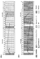
- FIG. 3 is a diagram showing an example of priority control based on the latest instruction information according to the second aspect.
- an SFI indicating an Unknown resource is detected in a slot after DL assignment / UL grant.
- PDSCH in one or more slots is scheduled by a single DL assignment.
- the radio base station transmits, in slot # 0, a DL assignment indicating that symbols # 1 to # 13 of slot # 0 and symbols # 1 to # 13 of slot # 1 are assigned to PDSCH. .
- the user terminal monitors CORESET in slot # 0 to detect the DL assignment.
- the user terminal detects DCI including SFI in slot # 1 after slot # 0 in which the DL assignment is detected. For example, in FIG. 3A, in slot # 1, SFI indicating that symbols # 6 to # 8 in slot # 1 are secured as an Unknown resource is detected. The user terminal does not receive the PDSCH based on the DL assignment detected in slot # 0 in the Unknown resource indicated by the SFI detected in slot # 1.
- PUSCH in one or more slots is scheduled by a single UL grant.
- the radio base station transmits, in slot # 0, a UL grant indicating that symbols # 2 to # 13 in slot # 0 and symbols # 2 to # 13 in slot # 1 are assigned to the PUSCH.
- the user terminal monitors CORESET in slot # 0 to detect the UL grant.
- the user terminal detects DCI including SFI in slot # 1 after slot # 0 in which the UL grant is detected. For example, in FIG. 3B, in slot # 1, an SFI indicating that symbols # 6 to # 8 in slot # 1 are secured as an Unknown resource is detected. The user terminal does not transmit the PUSCH based on the UL grant detected in slot # 0 in the Unknown resource indicated by the SFI detected in slot # 1.
- the Unknown resource is specified by SFI in slot # 1.
- a predetermined timing for example, scheduling timing of PDSCH / PUSCH
- Unknown on the transmission side radio base station in DL, user terminal in UL
- DL data and / or UL data may be decoded in consideration of the Unknown resource at the reception side (user terminal in DL, radio base station in UL) by the puncturing.
- the feedback timing of delivery acknowledgment information (HARQ-ACK) for PDSCH / PUSCH is determined regardless of whether the time / frequency resource scheduled to the PDSCH / PUSCH includes an Unknown resource or not. It may be done.
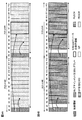
- FIG. 4 is a diagram showing another example of priority control based on the latest instruction information according to the second aspect.
- the DL assignment / UL grant is detected in a slot later than the SFI indicating the Unknown resource.
- the user terminal monitors the CORESET in slot # 0 and schedules a PDSCH in slot # 0 in DL assignment and DCI including SFI indicating an Unknown resource reserved in slot # 1. To detect.
- the user terminal monitors CORESET in slot # 1 after slot # 0 and detects DL assignment for scheduling the PDSCH in slot # 1.
- the PDSCH is scheduled to the symbols # 1 to # 13 including the Unknown resource indicated by the SFI detected in the previous slot # 0 according to the DL assignment.
- the user terminal prioritizes the DL assignment detected in later slot # 1 over the SFI detected in previous slot # 0. Specifically, in slot # 1, the user terminal uses PDSCH based on the DL assignment detected in slot # 1 in symbols # 1 to # 13 including symbols # 6 to # 8 indicated by SFI as an Unknown resource. Receive.
- FIG. 4B PUSCH in a slot in which the UL grant is detected by the UL grant is scheduled.
- CORESET in slot # 0 is monitored to detect a UL grant for scheduling the PUSCH in slot # 0 and a DCI including an SFI indicating an Unknown resource reserved in slot # 1.
- the user terminal monitors CORESET in slot # 1 after slot # 0 and detects a UL grant for scheduling the PUSCH in slot # 1.
- the PUSCH is scheduled to the symbols # 1 to # 13 including the Unknown resource indicated by the SFI detected in the previous slot # 0 according to the UL grant.
- the user terminal prioritizes the UL grant detected in later slot # 1 over the SFI detected in previous slot # 0. Specifically, the user terminal transmits the PUSCH based on the UL grant detected in slot # 1 in symbols # 2 to # 13 including symbols # 6 to # 8 indicated by SFI as an Unknown resource in slot # 1. I do.
- FIGS. 5 and 6 differ from FIGS. 3 and 4 in that the Unknown resource is prioritized regardless of whether the DL assignment / UL grant is detected in a slot before or after the SFI indicating the Unknown resource. .
- FIG. 5 is a diagram showing an example of priority control of the Unknown resource according to the second aspect.
- an SFI indicating an Unknown resource is detected in a slot after DL assignment / UL grant.
- the detailed operations of the radio base station and the user terminal in FIGS. 5A and 5B are similar to those in FIGS. 3A and 3B, respectively.
- FIG. 6 is a diagram illustrating another example of priority control of the Unknown resource according to the second aspect. 6A and 6B, DL assignment / UL grant for scheduling time / frequency resources including Unknown resource to PDSCH / PUSCH is detected in a slot later than SFI indicating Unknown resource.
- the user terminal monitors the CORESET in slot # 0 and schedules the PDSCH in slot # 0 DL assignment and SFI indicating the Unknown resource secured in slot # 1. And detect DCI.
- the user terminal also monitors CORESET in slot # 1 and detects DL assignment for scheduling the PDSCH in slot # 1.
- the user terminal monitors the CORESET in slot # 0 and includes a UL grant for scheduling the PUSCH in slot # 0 and an SFI indicating an Unknown resource reserved in slot # 1. Detect DCI. Also, the user terminal monitors CORESET in slot # 1 and detects a UL grant for scheduling the PUSCH in slot # 1.
- the Unknown resource is specified by SFI in slot # 1 before PDSCH / PUSCH is scheduled in slot # 0.
- the Unknown resource is considered on the transmission side (the radio base station in DL, the user terminal in UL) it can. Therefore, by the above rate matching, DL data and / or UL data may be encoded and / or mapped in consideration of an Unknown resource at the transmitting side (radio base station in DL, user terminal in UL).
- the feedback timing of delivery acknowledgment information (HARQ-ACK) for PDSCH / PUSCH is determined regardless of whether the time / frequency resource scheduled to the PDSCH / PUSCH includes an Unknown resource or not. It may be done.
- the user terminal receives PDSCH in the Unknown resource and And / or do not transmit PUSCH. This makes it possible to secure the Unknown resource more reliably.
- the user terminal can receive and / or receive PDSCH. Or transmission of PUSCH can be controlled appropriately.
- the priority control according to the second aspect may be controlled by higher layer signaling (eg, RRC signaling).
- higher layer signaling eg, RRC signaling
- priority control based on the latest indication information may be applied.
- priority control based on the latest instruction information may not be applied, and the priority control of the Unknown resource may be applied.
- wireless communication system Wireless communication system
- the wireless communication method according to each of the above aspects is applied.
- the wireless communication methods according to the above aspects may be applied singly or in combination.
- FIG. 7 is a diagram showing an example of a schematic configuration of a wireless communication system according to the present embodiment.
- the radio communication system 1 applies carrier aggregation (CA) and / or dual connectivity (DC) in which a plurality of basic frequency blocks (component carriers) each having a system bandwidth (for example, 20 MHz) of the LTE system as one unit are integrated. can do.
- the wireless communication system 1 may be called SUPER 3G, LTE-A (LTE-Advanced), IMT-Advanced, 4G, 5G, FRA (Future Radio Access), NR (New RAT), or the like.
- the radio communication system 1 shown in FIG. 7 includes a radio base station 11 forming a macrocell C1, and radio base stations 12a to 12c disposed in the macrocell C1 and forming a small cell C2 narrower than the macrocell C1. .
- the user terminal 20 is arrange
- the configuration may be such that different mermorologies are applied between cells.
- the terminology may be at least one of subcarrier spacing, symbol length, cyclic prefix (CP) length, number of symbols per transmission time interval (TTI), and TTI time length.
- the slot may be a unit of time based on the terminology applied by the user terminal. The number of symbols per slot may be determined according to the subcarrier spacing.
- the user terminal 20 can be connected to both the radio base station 11 and the radio base station 12.
- the user terminal 20 is assumed to simultaneously use the macro cell C1 and the small cell C2 using different frequencies by CA or DC.
- the user terminal 20 can apply CA or DC using a plurality of cells (CCs) (for example, two or more CCs).
- the user terminal can use the license band CC and the unlicensed band CC as a plurality of cells.
- the user terminal 20 can perform communication in each cell (carrier) using time division duplex (TDD) or frequency division duplex (FDD).
- TDD time division duplex
- FDD frequency division duplex
- the TDD cell and the FDD cell may be respectively referred to as a TDD carrier (frame configuration second type), an FDD carrier (frame configuration first type), and the like.
- a slot having a relatively long time length eg, 1 ms
- TTI normal TTI
- long TTI long TTI
- normal subframe also referred to as long subframe or subframe, etc.
- a slot having a relatively short time length also referred to as a mini slot, a short TTI or a short subframe, etc.
- two or more time slots may be applied in each cell.
- Communication can be performed between the user terminal 20 and the radio base station 11 using a relatively low frequency band (for example, 2 GHz) and a carrier having a narrow bandwidth (referred to as an existing carrier, Legacy carrier, etc.).
- a carrier having a wide bandwidth in a relatively high frequency band for example, 3.5 GHz, 5 GHz, 30 to 70 GHz, etc.
- the same carrier as that for the base station 11 may be used.
- the configuration of the frequency band used by each wireless base station is not limited to this.
- one or more BWPs may be set in the user terminal 20.
- the BWP consists of at least part of the carrier.
- a wired connection for example, an optical fiber conforming to a Common Public Radio Interface (CPRI), an X2 interface, etc.
- a wireless connection Can be configured.
- the radio base station 11 and each radio base station 12 are connected to the higher station apparatus 30 and connected to the core network 40 via the higher station apparatus 30.
- the upper station apparatus 30 includes, for example, an access gateway apparatus, a radio network controller (RNC), a mobility management entity (MME), and the like, but is not limited thereto. Further, each wireless base station 12 may be connected to the higher station apparatus 30 via the wireless base station 11.
- RNC radio network controller
- MME mobility management entity
- the radio base station 11 is a radio base station having a relatively wide coverage, and may be called a macro base station, an aggregation node, an eNB (eNodeB), a transmission / reception point, or the like.
- the radio base station 12 is a radio base station having local coverage, and is a small base station, a micro base station, a pico base station, a femto base station, a HeNB (Home eNodeB), an RRH (Remote Radio Head), transmission and reception It may be called a point or the like.
- the radio base stations 11 and 12 are not distinguished, they are collectively referred to as the radio base station 10.
- Each user terminal 20 is a terminal compatible with various communication schemes such as LTE and LTE-A, and may include not only mobile communication terminals but also fixed communication terminals. Also, the user terminal 20 can perform inter-terminal communication (D2D) with another user terminal 20.
- D2D inter-terminal communication
- OFDMA Orthogonal Frequency Division Multiple Access
- SC-FDMA Single Carrier-Frequency Division Multiple Access
- OFDMA is a multicarrier transmission scheme in which a frequency band is divided into a plurality of narrow frequency bands (subcarriers) and data is mapped to each subcarrier to perform communication.
- SC-FDMA is a single carrier transmission scheme that divides the system bandwidth into bands consisting of one or continuous resource blocks for each terminal, and a plurality of terminals use different bands to reduce interference between the terminals. is there.
- the uplink and downlink radio access schemes are not limited to these combinations, and OFDMA may be used in UL.
- SC-FDMA can be applied to a side link (SL) used for communication between terminals.
- SL side link
- DL data channels (PDSCH: also referred to as Physical Downlink Shared Channel, DL shared channel etc.) shared by each user terminal 20, broadcast channel (PBCH: Physical Broadcast Channel), L1 / L2 A control channel or the like is used.
- DL data (at least one of user data, upper layer control information, SIB (System Information Block), etc.) is transmitted by the PDSCH.
- SIB System Information Block
- MIB Master Information Block
- the L1 / L2 control channel is a DL control channel (PDCCH (Physical Downlink Control Channel) and / or EPDCCH (Enhanced Physical Downlink Control Channel)), PCFICH (Physical Control Format Indicator Channel), PHICH (Physical Hybrid-ARQ Indicator Channel), etc. including.
- Downlink control information (DCI) including scheduling information of PDSCH and PUSCH is transmitted by PDCCH.
- the number of OFDM symbols used for PDCCH is transmitted by PCFICH.
- the EPDCCH is frequency division multiplexed with the PDSCH, and is used for transmission such as DCI as the PDCCH.
- the PHICH can transmit PUSCH delivery confirmation information (also referred to as A / N, HARQ-ACK, HARQ-ACK bit, A / N codebook, etc.).
- a UL data channel shared by each user terminal 20 (PUSCH: also referred to as Physical Uplink Shared Channel, UL shared channel, etc.), UL control channel (PUCCH: Physical Uplink Control Channel), random An access channel (PRACH: Physical Random Access Channel) or the like is used.
- UL data (user data and / or upper layer control information) is transmitted by the PUSCH.
- Uplink control information (UCI: Uplink Control Information) including at least one of PDSCH delivery acknowledgment information (A / N, HARQ-ACK) channel state information (CSI) and the like is transmitted by the PUSCH or PUCCH.
- the PRACH can transmit a random access preamble for establishing a connection with a cell.
- FIG. 8 is a diagram showing an example of the entire configuration of the radio base station according to the present embodiment.
- the radio base station 10 includes a plurality of transmitting and receiving antennas 101, an amplifier unit 102, a transmitting and receiving unit 103, a baseband signal processing unit 104, a call processing unit 105, and a transmission path interface 106.
- Each of the transmitting and receiving antenna 101, the amplifier unit 102, and the transmitting and receiving unit 103 may be configured to include one or more.
- the radio base station 10 may configure a “receiving device” in UL and may configure a “transmitting device” in DL.
- User data transmitted from the radio base station 10 to the user terminal 20 by downlink is input from the higher station apparatus 30 to the baseband signal processing unit 104 via the transmission path interface 106.
- the baseband signal processing unit 104 performs packet data convergence protocol (PDCP) layer processing, user data division / combination, RLC layer transmission processing such as RLC (Radio Link Control) retransmission control, and MAC (Medium Access) for user data.
- Control Retransmission control (for example, processing of HARQ (Hybrid Automatic Repeat reQuest)), scheduling, transmission format selection, channel coding, rate matching, scrambling, Inverse Fast Fourier Transform (IFFT) processing and precoding Transmission processing such as at least one of the processing is performed and transferred to the transmission / reception unit 103.
- HARQ Hybrid Automatic Repeat reQuest
- IFFT Inverse Fast Fourier Transform
- Transmission processing such as at least one of the processing is performed and transferred to the transmission / reception unit 103.
- transmission processing such as channel coding and / or inverse fast Fourier transform is performed and transferred to the transmission / reception unit 103.
- the transmission / reception unit 103 converts the baseband signal output from the baseband signal processing unit 104 for each antenna into a radio frequency band and transmits the baseband signal.
- the radio frequency signal frequency-converted by the transmitting and receiving unit 103 is amplified by the amplifier unit 102 and transmitted from the transmitting and receiving antenna 101.
- the transmitter / receiver, the transmitting / receiving circuit or the transmitting / receiving device described based on the common recognition in the technical field according to the present invention can be constituted.
- the transmitting and receiving unit 103 may be configured as an integrated transmitting and receiving unit, or may be configured from a transmitting unit and a receiving unit.
- the radio frequency signal received by the transmitting and receiving antenna 101 is amplified by the amplifier unit 102.
- the transmitting and receiving unit 103 receives the UL signal amplified by the amplifier unit 102.
- the transmission / reception unit 103 frequency-converts the received signal into a baseband signal and outputs the result to the baseband signal processing unit 104.
- the baseband signal processing unit 104 performs Fast Fourier Transform (FFT) processing, Inverse Discrete Fourier Transform (IDFT) processing, and error correction on UL data included in the input UL signal. Decoding, reception processing of MAC retransmission control, and reception processing of RLC layer and PDCP layer are performed, and are transferred to the higher station apparatus 30 via the transmission path interface 106.
- the call processing unit 105 performs at least one of setting of a communication channel, call processing such as release, status management of the radio base station 10, and management of radio resources.
- the transmission path interface 106 transmits and receives signals to and from the higher station apparatus 30 via a predetermined interface. Also, the transmission path interface 106 transmits / receives signals (backhaul signaling) to / from the adjacent wireless base station 10 via an inter-base station interface (for example, an optical fiber conforming to CPRI (Common Public Radio Interface), X2 interface). It is also good.
- an inter-base station interface for example, an optical fiber conforming to CPRI (Common Public Radio Interface), X2 interface.
- the transmission / reception unit 103 may be a DL signal (for example, at least one of a DL control signal (also referred to as DL control channel or DCI), a DL data signal (also referred to as DL data channel or DL data), and a reference signal)
- a DL control signal also referred to as DL control channel or DCI
- a DL data signal also referred to as DL data channel or DL data
- a reference signal Send
- the transmission / reception unit 103 may be a UL signal (for example, at least one of a UL control signal (also referred to as UL control channel or UCI), a UL data signal (also referred to as UL data channel or UL data), and a reference signal)
- the transmission / reception unit 103 transmits slot related information (SFI).
- SFI slot related information
- the SFI may be included in DCI common to one or more user terminals 20 or may be included in other control information.
- the transmission / reception unit 103 may transmit DCI (DL assignment and / or UL grant) including scheduling information of a data channel (DL data channel and / or UL data channel) for the user terminal 20.
- the transmission / reception unit 103 may transmit upper layer control information.
- FIG. 9 is a diagram showing an example of a functional configuration of the radio base station according to the present embodiment. Note that FIG. 9 mainly shows the functional blocks of the characterizing portion in the present embodiment, and the wireless base station 10 also has other functional blocks necessary for wireless communication.
- the baseband signal processing unit 104 includes a control unit 301, a transmission signal generation unit 302, a mapping unit 303, a reception signal processing unit 304, and a measurement unit 305.
- the control unit 301 controls the entire wireless base station 10.
- the control unit 301 may, for example, generate a DL signal by the transmission signal generation unit 302, map the DL signal by the mapping unit 303, receive processing (for example, demodulation) of the UL signal by the reception signal processing unit 304, and measure it by the measurement unit 305. Control at least one of
- the control unit 301 is a symbol in a time resource (eg, one or more slots, one or more minislots, at least one of one or more symbols) serving as a scheduling unit of a data channel (DL data channel and / or UL data channel) Each transmission direction may be controlled. Specifically, the control unit 301 may control generation and / or transmission of an SFI indicating DL symbols and / or UL symbols in a slot.
- a time resource eg, one or more slots, one or more minislots, at least one of one or more symbols
- Each transmission direction may be controlled.
- the control unit 301 may control generation and / or transmission of an SFI indicating DL symbols and / or UL symbols in a slot.
- control unit 301 controls securing (setting) of time and / or frequency resources (Unknown resources) in which reception and / or transmission is not expected in the user terminal 20. Specifically, the control unit 301 may control generation and / or transmission of a predetermined symbol secured as an Unknown resource and an SFI indicating a predetermined frequency resource.
- control unit 301 may perform scheduling of a data channel (DL data channel and / or UL data channel) based on the Unknown resource (first aspect, FIG. 1). Specifically, the control unit 301 may schedule the data channel to a time / frequency resource that does not overlap with the Unknown resource.
- control unit 301 may perform scheduling of the data channel (DL data channel and / or UL data channel) regardless of the Unknown resource (first and second aspects, FIGS. 2 and 3 to 6). .
- control unit 301 may control transmission and / or reception of data channels (DL data channels and / or UL data channels). Specifically, the control unit 301 determines the size (size of TB (Transport Block Size)) of DL data and / or UL data (transport block (TB)) without considering the Unknown resource. May be (in the case of puncturing).
- size of TB Transport Block Size
- TB transport block
- control unit 301 may control DL data transmission processing (for example, at least one of encoding, modulation, and mapping) without considering the Unknown resource.
- control unit 301 may control reception processing (for example, at least one of reception, demodulation, and decoding) of UL data in consideration of the Unknown resource.
- control unit 301 may determine the size (TBS) of DL data and / or UL data (TB) in consideration of an Unknown resource (in the case of rate matching). In the case of rate matching, the control unit 301 may control transmission processing (for example, at least one of encoding, modulation, and mapping) of DL data in consideration of an Unknown resource. Also, the control unit 301 may control reception processing (for example, at least one of reception, demodulation, and decoding) of UL data without considering the Unknown resource.
- the control unit 301 can be configured of a controller, a control circuit, or a control device described based on the common recognition in the technical field according to the present invention.
- the transmission signal generation unit 302 generates a DL signal (including at least one of DL data (channel), DCI, DL reference signal, and control information by upper layer signaling) based on an instruction from the control unit 301, It may be output to the mapping unit 303.
- the transmission signal generation unit 302 can be a signal generator, a signal generation circuit or a signal generation device described based on the common recognition in the technical field according to the present invention.
- the mapping unit 303 maps the DL signal generated by the transmission signal generation unit 302 on a predetermined radio resource based on an instruction from the control unit 301, and outputs the DL signal to the transmission / reception unit 103.
- the mapping unit 303 maps the reference signal to a predetermined radio resource using the arrangement pattern determined by the control unit 301.
- the mapping unit 303 may be a mapper, a mapping circuit or a mapping device described based on the common recognition in the technical field according to the present invention.
- the reception signal processing unit 304 performs reception processing (for example, at least one of demapping, demodulation, and decoding) of the UL signal transmitted from the user terminal 20. Specifically, the reception signal processing unit 304 may output the reception signal and / or the signal after reception processing to the measurement unit 305.
- reception processing for example, at least one of demapping, demodulation, and decoding
- the received signal processing unit 304 can be configured from a signal processor, a signal processing circuit or a signal processing device described based on the common recognition in the technical field according to the present invention. Also, the received signal processing unit 304 can constitute a receiving unit according to the present invention.
- the measurement unit 305 measures the channel quality of UL based on, for example, received power of a reference signal (for example, reference signal received power (RSRP)) and / or received quality (for example, reference signal received quality (RSRQ)). May be The measurement result may be output to the control unit 301.
- a reference signal for example, reference signal received power (RSRP)
- RSSQ reference signal received quality
- FIG. 10 is a diagram showing an example of the entire configuration of the user terminal according to the present embodiment.
- the user terminal 20 includes a plurality of transmission / reception antennas 201 for MIMO transmission, an amplifier unit 202, a transmission / reception unit 203, a baseband signal processing unit 204, and an application unit 205.
- the user terminal 20 may configure a “transmitting device” in UL and may configure a “receiving device” in DL.
- the radio frequency signals received by the plurality of transmitting and receiving antennas 201 are amplified by the amplifier unit 202, respectively.
- Each transmission / reception unit 203 receives the DL signal amplified by the amplifier unit 202.
- the transmission / reception unit 203 frequency-converts the received signal into a baseband signal and outputs the result to the baseband signal processing unit 204.
- the baseband signal processing unit 204 performs at least one of FFT processing, error correction decoding, reception processing of retransmission control, and the like on the input baseband signal.
- the DL data is transferred to the application unit 205.
- the application unit 205 performs processing on a layer higher than the physical layer and the MAC layer.
- UL data is input from the application unit 205 to the baseband signal processing unit 204.
- the baseband signal processing unit 204 performs at least one of retransmission control processing (for example, processing of HARQ), channel coding, rate matching, puncturing, discrete Fourier transform (DFT) processing, IFFT processing, and the like.
- the data is transferred to each transmission / reception unit 203.
- UCI eg, A / N of DL signal, channel state information (CSI), scheduling request (SR), etc.
- CSI channel state information
- SR scheduling request
- the transmission / reception unit 203 converts the baseband signal output from the baseband signal processing unit 204 into a radio frequency band and transmits it.
- the radio frequency signal frequency-converted by the transmitting and receiving unit 203 is amplified by the amplifier unit 202 and transmitted from the transmitting and receiving antenna 201.
- the transmitting / receiving unit 203 is a DL signal (for example, at least one of a DL control signal (also referred to as DL control channel or DCI), a DL data signal (also referred to as DL data channel or DL data), and a reference signal) Receive
- the transmission / reception unit 203 is a UL signal (for example, at least one of a UL control signal (also referred to as a UL control channel or UCI), a UL data signal (also referred to as a UL data channel or UL data), and a reference signal)
- a DL control signal also referred to as DL control channel or DCI
- a DL data signal also referred to as DL data channel or DL data
- a reference signal for example, at least one of a UL control signal (also referred to as a UL control channel or UCI), a UL data signal (also referred to as a UL data channel or UL data), and a reference signal)
- the transmission / reception unit 203 receives slot related information (SFI).
- SFI slot related information
- the SFI may be included in DCI common to one or more user terminals 20, or may be included in other control information.
- the transmission / reception unit 203 may receive DCI (DL assignment and / or UL grant) including scheduling information of a data channel (DL data channel and / or UL data channel) for the user terminal 20.
- the transmitting / receiving unit 203 may receive upper layer control information.
- the transmission / reception unit 203 can be a transmitter / receiver, a transmission / reception circuit or a transmission / reception device described based on the common recognition in the technical field according to the present invention.
- the transmission / reception unit 203 may be configured as an integrated transmission / reception unit, or may be configured from a transmission unit and a reception unit.
- FIG. 11 is a diagram showing an example of a functional configuration of the user terminal according to the present embodiment.
- the functional block of the characteristic part in this Embodiment is mainly shown, and it is assumed that the user terminal 20 also has another functional block required for wireless communication.
- the baseband signal processing unit 204 included in the user terminal 20 includes the control unit 401, the transmission signal generation unit 402, the mapping unit 403, the reception signal processing unit 404, and the measurement unit 405. Have.
- the control unit 401 controls the entire user terminal 20.
- the control unit 401 controls, for example, at least one of UL signal generation by the transmission signal generation unit 402, mapping of the UL signal by the mapping unit 403, reception processing of the DL signal by the reception signal processing unit 404, and measurement by the measurement unit 405. Do.
- control unit 401 may control DL control channel monitoring (blind decoding) and control detection of DCI (including group common DCI and / or UE specific DCI) for the user terminal 20.
- control unit 401 may monitor one or more CORESETs (or a search space in CORESET) set in the user terminal 20.
- control unit 401 may use at least one of time resources (for example, one or more slots, one or more minislots, one or more symbols) as a scheduling unit of the data channel (DL data channel and / or UL data channel). Specifically, the control unit 401 may determine DL symbols and / or UL symbols in the time resource based on the SFI.
- time resources for example, one or more slots, one or more minislots, one or more symbols
- control unit 401 may not assume reception and / or transmission in the time / frequency resource determined as the Unknown resource based on the SFI.
- control unit 401 may control reception and / or transmission of data channels (DL data channel and / or UL data channel) based on the DCI. Specifically, when at least a portion of time and / or frequency resources at which the data channel is scheduled by DCI (DL assignment and / or UL grant) and / or frequency resources collide with the Unknown resource indicated by SFI, The reception and / or transmission of data channels in the time and / or frequency resources may be controlled.
- the control unit 401 may determine the time and / or time of collision with the Unknown resource.
- the transceiver unit 203 may be controlled so that reception and / or reception of the data channel based on the DCI is not performed in the frequency resource (first aspect, FIG. 2, second aspect, FIG. 3, FIG. 5).
- control unit 401 receives and / or transmits the data channel based on the DCI in a time and / or frequency resource that collides with the Unknown resource.
- the transmission / reception unit 203 may be controlled to perform (second aspect, FIG. 4).
- control unit 401 receives and / or transmits the data channel based on the DCI in a time and / or frequency resource that collides with the Unknown resource.
- the transmission / reception unit 203 may be controlled so as not to be performed (second aspect, FIG. 6).
- control unit 401 performs transmission and reception so as to perform reception and / or transmission of a data channel based on the DCI in a time and / or frequency resource which does not collide with the Unknown resource among time and / or frequency resources scheduled by DCI.
- the unit 203 may be controlled (first and second aspects, FIGS. 1 to 6).
- control unit 401 may determine the size (TB size) of DL data and / or UL data (transport block (TB)) without considering the Unknown resource (in the case of puncture) .
- control unit 401 may control UL data transmission processing (for example, at least one of encoding, modulation, and mapping) without considering the Unknown resource.
- control unit 401 may control reception processing (for example, at least one of reception, demodulation, and decoding) of DL data in consideration of an Unknown resource.
- control unit 401 may determine the size (TBS) of DL data and / or UL data (TB) in consideration of an Unknown resource (in the case of rate matching). In the case of rate matching, the control unit 401 may control UL data transmission processing (for example, at least one of encoding, modulation, and mapping) in consideration of an Unknown resource. Also, the control unit 401 may control reception processing (for example, at least one of reception, demodulation, and decoding) of DL data without considering the Unknown resource.
- TCS size
- UL data transmission processing for example, at least one of encoding, modulation, and mapping
- reception processing for example, at least one of reception, demodulation, and decoding
- the control unit 401 can be configured of a controller, a control circuit or a control device described based on the common recognition in the technical field according to the present invention.
- Transmission signal generation unit 402 generates retransmission control information of UL signal and DL signal (for example, coding, rate matching, puncturing, modulation, etc.) based on an instruction from control unit 401, and outputs the result to mapping unit 403. Do.
- the transmission signal generation unit 402 can be a signal generator, a signal generation circuit, or a signal generation device described based on the common recognition in the technical field according to the present invention.
- the mapping unit 403 maps retransmission control information of the UL signal and the DL signal generated by the transmission signal generation unit 402 to radio resources based on an instruction from the control unit 401, and outputs the retransmission control information to the transmission / reception unit 203.
- the mapping unit 403 maps the reference signal to a predetermined radio resource, using the arrangement pattern determined by the control unit 401.
- the mapping unit 403 may be a mapper, a mapping circuit or a mapping device described based on the common recognition in the technical field according to the present invention.
- the reception signal processing unit 404 performs reception processing (for example, at least one of demapping, demodulation, and decoding) of the DL signal.
- reception processing for example, at least one of demapping, demodulation, and decoding
- the reception signal processing unit 404 may demodulate the DL data channel using the reference signal of the arrangement pattern determined by the control unit 401.
- the reception signal processing unit 404 may output the reception signal and / or the signal after reception processing to the control unit 401 and / or the measurement unit 405.
- the reception signal processing unit 404 outputs, for example, upper layer control information by upper layer signaling, L1 / L2 control information (for example, UL grant and / or DL assignment), and the like to the control unit 401.
- the received signal processing unit 404 can be composed of a signal processor, a signal processing circuit or a signal processing device described based on the common recognition in the technical field according to the present invention. Also, the received signal processing unit 404 can constitute a receiving unit according to the present invention.
- Measuring section 405 measures a channel state based on a reference signal (for example, CSI-RS) from radio base station 10, and outputs the measurement result to control section 401.
- the channel state measurement may be performed for each CC.
- the measuring unit 405 can be configured of a signal processor, a signal processing circuit or a signal processing device, and a measuring instrument, a measuring circuit or a measuring device described based on the common recognition in the technical field according to the present invention.
- each functional block is realized by one physically and / or logically coupled device, or directly and / or indirectly two or more physically and / or logically separated devices. It may be connected by (for example, wired and / or wireless) and realized by the plurality of devices.
- the wireless base station, the user terminal, and the like in the present embodiment may function as a computer that performs the process of the wireless communication method of the present invention.
- FIG. 12 is a diagram showing an example of the hardware configuration of the radio base station and the user terminal according to the present embodiment.
- the above-described wireless base station 10 and user terminal 20 may be physically configured as a computer device including a processor 1001, a memory 1002, a storage 1003, a communication device 1004, an input device 1005, an output device 1006, a bus 1007 and the like. Good.
- the term “device” can be read as a circuit, a device, a unit, or the like.
- the hardware configuration of the radio base station 10 and the user terminal 20 may be configured to include one or more of the devices illustrated in the figure, or may be configured without including some devices.
- processor 1001 may be implemented by one or more chips.
- Each function in the radio base station 10 and the user terminal 20 is performed, for example, by causing a processor 1001 to read predetermined software (program) on hardware such as the processor 1001 and the memory 1002, and the processor 1001 performs an operation. This is realized by controlling at least one of reading and writing of data in the memory 1002 and the storage 1003.
- the processor 1001 operates, for example, an operating system to control the entire computer.
- the processor 1001 may be configured by a central processing unit (CPU: Central Processing Unit) including an interface with a peripheral device, a control device, an arithmetic device, a register, and the like.
- CPU Central Processing Unit
- the above-described baseband signal processing unit 104 (204), call processing unit 105, and the like may be realized by the processor 1001.
- the processor 1001 reads a program (program code), a software module, data, and the like from the storage 1003 and / or the communication device 1004 to the memory 1002, and executes various processing according to these.
- a program a program that causes a computer to execute at least a part of the operations described in the above embodiments is used.
- the control unit 401 of the user terminal 20 may be realized by a control program stored in the memory 1002 and operated by the processor 1001, or may be realized similarly for other functional blocks.
- the memory 1002 is a computer readable recording medium, and for example, at least at least a read only memory (ROM), an erasable programmable ROM (EPROM), an electrically EPROM (EEPROM), a random access memory (RAM), or any other suitable storage medium. It may consist of one.
- the memory 1002 may be called a register, a cache, a main memory (main storage device) or the like.
- the memory 1002 may store a program (program code), a software module, and the like that can be executed to implement the wireless communication method according to an embodiment of the present invention.
- the storage 1003 is a computer readable recording medium, and for example, a flexible disk, a floppy (registered trademark) disk, a magneto-optical disk (for example, a compact disk (CD-ROM (Compact Disc ROM), etc.), a digital versatile disk, Blu-ray® disc), removable disc, hard disc drive, smart card, flash memory device (eg card, stick, key drive), magnetic stripe, database, server, at least one other suitable storage medium May be composed of
- the storage 1003 may be called an auxiliary storage device.
- the communication device 1004 is hardware (transmission / reception device) for performing communication between computers via a wired and / or wireless network, and is also called, for example, a network device, a network controller, a network card, a communication module, or the like.
- the communication device 1004 includes, for example, a high frequency switch, a duplexer, a filter, a frequency synthesizer, and the like to realize, for example, frequency division duplex (FDD) and / or time division duplex (TDD). It may be configured.
- FDD frequency division duplex
- TDD time division duplex
- the transmission / reception antenna 101 (201), the amplifier unit 102 (202), the transmission / reception unit 103 (203), the transmission path interface 106, and the like described above may be realized by the communication device 1004.
- the input device 1005 is an input device (for example, a keyboard, a mouse, a microphone, a switch, a button, a sensor, and the like) that receives an input from the outside.
- the output device 1006 is an output device (for example, a display, a speaker, a light emitting diode (LED) lamp, and the like) that performs output to the outside.
- the input device 1005 and the output device 1006 may be integrated (for example, a touch panel).
- the devices shown in FIG. 12 are connected by a bus 1007 for communicating information.
- the bus 1007 may be configured by a single bus or may be configured by different buses among the devices.
- radio base station 10 and the user terminal 20 may be microprocessors, digital signal processors (DSPs), application specific integrated circuits (ASICs), programmable logic devices (PLDs), field programmable gate arrays (FPGAs), etc. It may be configured to include hardware, and part or all of each functional block may be realized by the hardware. For example, processor 1001 may be implemented in at least one of these hardware.
- DSPs digital signal processors
- ASICs application specific integrated circuits
- PLDs programmable logic devices
- FPGAs field programmable gate arrays
- the channels and / or symbols may be signaling.
- the signal may be a message.
- the reference signal may be abbreviated as RS (Reference Signal), and may be referred to as a pilot (Pilot), a pilot signal or the like according to an applied standard.
- a component carrier CC: Component Carrier
- CC Component Carrier
- a radio frame may be configured with one or more periods (frames) in the time domain.
- Each of the one or more periods (frames) that constitute a radio frame may be referred to as a subframe.
- a subframe may be configured with one or more slots in the time domain.
- the subframes may be of a fixed time length (e.g., 1 ms) independent of the neurology.
- a slot may be configured with one or more symbols (such as orthogonal frequency division multiplexing (OFDM) symbols, single carrier frequency division multiple access (SC-FDMA) symbols, etc.) in the time domain.
- the slot may be a time unit based on the neurology.
- the slot may include a plurality of minislots. Each minislot may be comprised of one or more symbols in the time domain.
- a radio frame, a subframe, a slot, a minislot and a symbol all represent time units when transmitting a signal.
- subframes, slots, minislots and symbols other names corresponding to each may be used.
- one subframe may be referred to as a transmission time interval (TTI)
- TTI transmission time interval
- a plurality of consecutive subframes may be referred to as a TTI
- one slot or one minislot may be referred to as a TTI.
- TTI transmission time interval
- the subframe and / or TTI may be a subframe (1 ms) in existing LTE, a period shorter than 1 ms (eg, 1-13 symbols), or a period longer than 1 ms. It may be.
- TTI refers to, for example, the minimum time unit of scheduling in wireless communication.
- the radio base station performs scheduling to allocate radio resources (such as frequency bandwidth and / or transmission power that can be used in each user terminal) to each user terminal on a TTI basis.
- the TTI may be a transmission time unit of a channel coded data packet (transport block) or may be a processing unit such as scheduling and / or link adaptation. If one slot or one minislot is referred to as TTI, one or more TTIs (ie, one or more slots or one or more minislots) may be the minimum time unit of scheduling. In addition, the number of slots (the number of minislots) constituting the minimum time unit of the scheduling may be controlled.
- a TTI having a time length of 1 ms may be referred to as a normal TTI (TTI in LTE Rel. 8-12), a normal TTI, a long TTI, a normal subframe, a normal subframe, a long subframe, or the like.
- a TTI shorter than a normal TTI may be referred to as a short TTI, a short TTI, a partial TTI (partial or fractional TTI), a short subframe, a short subframe, or the like.
- a resource block is a resource allocation unit in time domain and frequency domain, and may include one or more consecutive subcarriers (subcarriers) in the frequency domain. Also, an RB may include one or more symbols in the time domain, and may be one slot, one minislot, one subframe, or one TTI in length. One TTI and one subframe may be configured of one or more resource blocks, respectively.
- the RB may be called a physical resource block (PRB: Physical RB), a PRB pair, an RB pair, or the like.
- a resource block may be composed of one or more resource elements (RE: Resource Element).
- RE Resource Element
- one RE may be one subcarrier and one symbol radio resource region.
- the above-described structures such as the radio frame, subframe, slot, minislot and symbol are merely examples.
- the number of subframes included in a radio frame the number of slots per subframe or radio frame, the number of minislots included in a slot, the number of symbols included in a slot or minislot, and subcarriers included in an RB
- the number of symbols in TTI, symbol length, cyclic prefix (CP) length, and other configurations may be variously changed.
- the information, parameters, and the like described in the present specification may be represented by absolute values, may be represented by relative values from predetermined values, or may be represented by corresponding other information.
- the radio resources may be indicated by a predetermined index.
- the formulas etc. that use these parameters may differ from those explicitly disclosed herein.
- data, instructions, commands, information, signals, bits, symbols, chips etc may be voltage, current, electromagnetic waves, magnetic fields or particles, optical fields or photons, or any of these May be represented by a combination of
- information, signals, etc. may be output from the upper layer to the lower layer and / or from the lower layer to the upper layer.
- Information, signals, etc. may be input / output via a plurality of network nodes.
- the input / output information, signals and the like may be stored in a specific place (for example, a memory) or may be managed by a management table. Information, signals, etc. input and output can be overwritten, updated or added. The output information, signals and the like may be deleted. The input information, signals and the like may be transmitted to other devices.
- notification of information is not limited to the aspects / embodiments described herein, and may be performed in other manners.
- notification of information may be physical layer signaling (eg, downlink control information (DCI), uplink control information (UCI)), upper layer signaling (eg, RRC (Radio Resource Control) signaling, It may be implemented by broadcast information (Master Information Block (MIB), System Information Block (SIB), etc.), MAC (Medium Access Control) signaling, other signals, or a combination thereof.
- DCI downlink control information
- UCI uplink control information
- RRC Radio Resource Control
- MIB Master Information Block
- SIB System Information Block
- MAC Medium Access Control
- the physical layer signaling may be called L1 / L2 (Layer 1 / Layer 2) control information (L1 / L2 control signal), L1 control information (L1 control signal), or the like.
- RRC signaling may be referred to as an RRC message, and may be, for example, an RRC connection setup (RRC Connection Setup) message, an RRC connection reconfiguration (RRC Connection Reconfiguration) message, or the like.
- MAC signaling may be notified by, for example, a MAC control element (MAC CE (Control Element)).
- notification of predetermined information is not limited to what is explicitly performed, but implicitly (for example, by not notifying the predetermined information or another It may be performed by notification of information.
- the determination may be performed by a value (0 or 1) represented by one bit, or may be performed by a boolean value represented by true or false. , Numerical comparison (for example, comparison with a predetermined value) may be performed.
- Software may be called software, firmware, middleware, microcode, hardware description language, or any other name, and may be instructions, instruction sets, codes, code segments, program codes, programs, subprograms, software modules. Should be interpreted broadly to mean applications, software applications, software packages, routines, subroutines, objects, executables, threads of execution, procedures, functions, etc.
- software, instructions, information, etc. may be sent and received via a transmission medium.
- software may use a wired technology (coaxial cable, fiber optic cable, twisted pair, digital subscriber line (DSL), etc.) and / or a wireless technology (infrared, microwave, etc.), a website, a server
- wired technology coaxial cable, fiber optic cable, twisted pair, digital subscriber line (DSL), etc.
- wireless technology infrared, microwave, etc.
- system and "network” as used herein are used interchangeably.
- base station Base Station
- radio base station eNB
- gNB gNodeB
- cell cell
- cell group cell group
- carrier carrier
- component carrier component carrier
- a base station may also be called in terms of a fixed station (Node station), NodeB, eNodeB (eNB), access point (access point), transmission point, reception point, femtocell, small cell, and so on.
- a base station may accommodate one or more (e.g., three) cells (also called sectors). If the base station accommodates multiple cells, the entire coverage area of the base station can be partitioned into multiple smaller areas, each smaller area being a base station subsystem (eg, a small base station for indoor use (RRH: Communication services may also be provided by the Remote Radio Head, where the term "cell” or “sector” refers to part or all of the coverage area of a base station and / or a base station subsystem serving communication services in this coverage. Point to.
- RRH Small base station for indoor use
- MS mobile station
- UE user equipment
- a base station may also be called in terms of a fixed station (Node station), NodeB, eNodeB (eNB), access point (access point), transmission point, reception point, femtocell, small cell, and so on.
- Node station Node station
- NodeB NodeB
- eNodeB eNodeB
- access point access point
- transmission point reception point
- femtocell small cell, and so on.
- the mobile station may be a subscriber station, a mobile unit, a subscriber unit, a wireless unit, a remote unit, a mobile device, a wireless device, a wireless communication device, a remote device, a mobile subscriber station, an access terminal, a mobile terminal, a wireless terminal, by those skilled in the art. It may also be called a terminal, a remote terminal, a handset, a user agent, a mobile client, a client or some other suitable term.
- the radio base station in the present specification may be replaced with a user terminal.
- each aspect / embodiment of the present invention may be applied to a configuration in which communication between a wireless base station and a user terminal is replaced with communication between a plurality of user terminals (D2D: Device-to-Device).
- the user terminal 20 may have a function that the above-described radio base station 10 has.
- “up” and / or “down” may be read as “side”.
- the upstream channel may be read as a side channel.
- a user terminal herein may be read at a radio base station.
- the radio base station 10 may have a function that the above-described user terminal 20 has.
- the specific operation to be performed by the base station may be performed by the upper node in some cases.
- various operations performed for communication with a terminal may be a base station, one or more network nodes other than the base station (eg, It is apparent that this can be performed by MME (Mobility Management Entity), S-GW (Serving-Gateway), etc. but not limited thereto or a combination thereof.
- MME Mobility Management Entity
- S-GW Serving-Gateway
- Each aspect / embodiment described in the present specification includes LTE (Long Term Evolution), LTE-A (LTE-Advanced), LTE-B (LTE-Beyond), SUPER 3G, IMT-Advanced, 4G (4th generation mobile) Communication system), 5G (5th generation mobile communication system), FRA (Future Radio Access), New-RAT (Radio Access Technology), NR (New Radio), NX (New radio access), FX (Future generation radio access), GSM (registered trademark) (Global System for Mobile communications), CDMA2000, UMB (Ultra Mobile Broadband), IEEE 802.11 (Wi-Fi (registered trademark)), IEEE 802.16 (WiMAX (registered trademark)), IEEE 802 .20, UWB (Ultra-Wide Band), Bluetooth (registered trademark),
- the present invention may be applied to a system utilizing another appropriate wireless communication method of and / or an extended next generation system based on these.
- the phrase “based on” does not mean “based only on,” unless expressly stated otherwise. In other words, the phrase “based on” means both “based only on” and “based at least on.”
- any reference to an element using the designation "first,” “second,” etc. as used herein does not generally limit the quantity or order of those elements. These designations may be used herein as a convenient way of distinguishing between two or more elements. Thus, reference to the first and second elements does not mean that only two elements can be taken or that the first element must somehow precede the second element.
- determining may encompass a wide variety of operations. For example, “determination” may be calculating, computing, processing, deriving, investigating, looking up (eg, table, database or other data) A search on structure), ascertaining, etc. may be considered as “determining”. Also, “determination” may be receiving (e.g. receiving information), transmitting (e.g. transmitting information), input (input), output (output), access (access) It may be considered as “determining” (eg, accessing data in memory) and the like. Also, “determination” is considered to be “determination” to resolve, select, choose, choose, establish, compare, etc. It is also good. That is, “determination” may be considered as “determining” some action.
- the terms “connected”, “coupled”, or any variation thereof are any direct or indirect connection between two or more elements or It means a bond and can include the presence of one or more intermediate elements between two elements “connected” or “connected” to each other.
- the coupling or connection between elements may be physical, logical or a combination thereof.
- the two elements are by using one or more wires, cables and / or printed electrical connections, and radio frequency as some non-limiting and non-exclusive examples. It can be considered “connected” or “coupled” to one another by using electromagnetic energy such as electromagnetic energy having wavelengths in the region, microwave region and light (both visible and invisible) regions.
Abstract
Description
第1の態様では、Unknownリソースを示すSFI(当該SFIを含むDCI)と、PDSCHのスケジューリングに用いられるDCI(DLアサインメント)及び/又はPUSCHのスケジューリングに用いられるDCI(ULグラント)とが、同一のスロット内で検出される場合について説明する。 (First aspect)
In the first aspect, the SFI indicating the Unknown resource (the DCI including the SFI) and the DCI (DL assignment) used for PDSCH scheduling and / or the DCI (UL grant) used for PUSCH scheduling are the same. The case of being detected within the slot of will be described.
ユーザ端末は、SFIを含むDCIとDLアサインメント及び/又はULグラント(DLアサインメント/ULグラント)とが同一のスロット内で検出される場合、SFIによって示されるUnknownリソースには、PDSCH及び/又はPUSCH(PDSCH/PUSCH)がスケジューリングされないことを想定してもよい。 <Collision control by scheduling>
If the user terminal detects a DCI including SFI and a DL assignment and / or a UL grant (DL assignment / UL grant) in the same slot, the Unknown resource indicated by SFI may be a PDSCH and / or a PDSCH. It may be assumed that PUSCH (PDSCH / PUSCH) is not scheduled.
或いは、無線基地局は、Unknownリソースとして確保される時間/周波数リソースであるかに関係なく、PDSCH/PUSCHをスケジューリングしてもよい。この場合、ユーザ端末は、SFIによって示されるUnknownリソースでは、DLアサインメントに基づくPDSCHの受信及び/又はULグラントに基づくPUSCHの送信をしてはならない。 <Override control of Unknown resource>
Alternatively, the radio base station may schedule PDSCH / PUSCH regardless of whether it is a time / frequency resource reserved as an Unknown resource. In this case, the user terminal should not receive PDSCH based on DL assignment and / or transmit PUSCH based on UL grant in the Unknown resource indicated by SFI.
ユーザ端末は、PDSCH/PUSCHがスケジューリングされた時間/周波数リソース内のUnknownリソースを考慮せずに、当該PDSCH/PUSCHで送信されるDLデータ及び/又はULデータ(トランスポートブロック(TB:Transport Block))のサイズ(TBのサイズ(TBS:Transport Block Size))を決定してもよい。 «Puncture case»
The user terminal does not consider the Unknown resource in the time / frequency resource for which PDSCH / PUSCH is scheduled, and transmits DL data and / or UL data (transport block (TB: Transport Block) transmitted on the PDSCH / PUSCH) ) (TB size (TB: Transport Block Size)) may be determined.
或いは、ユーザ端末は、PDSCH/PUSCHがスケジューリングされる時間/周波数リソース内のUnknownリソースを考慮して、当該PDSCH/PUSCHで送信されるDLデータ及び/又はULデータ(TB)のサイズ(TBS)を決定してもよい。 «For rate matching»
Alternatively, the user terminal may determine the size (TBS) of DL data and / or UL data (TB) transmitted on the PDSCH / PUSCH in consideration of an Unknown resource in the time / frequency resource for which PDSCH / PUSCH is scheduled. You may decide.
第2の態様では、Unknownリソースを示すSFI(当該SFIを含むDCI)と、DLアサインメント/ULグラントとが、異なるスロット内で検出される場合について説明する。 (Second aspect)
In the second aspect, a case will be described in which an SFI (a DCI including the SFI) indicating an Unknown resource and a DL assignment / UL grant are detected in different slots.
ユーザ端末は、Unknownリソースを示すSFIと、DLアサインメント/ULグラントとが異なるスロットで検出される場合、最後に検出された指示情報(例えば、DLアサインメント/ULグラント(又は、SFI))を、前に検出された指示情報(例えば、SFI(又は、DLアサインメント/ULグラント))よりも優先(override)してもよい。 <Priority control based on the latest instruction information>
When the user terminal detects SFI indicating an Unknown resource and DL assignment / UL grant in different slots, the user terminal detects the last detected indication information (eg, DL assignment / UL grant (or SFI)). , And may be prioritized over previously detected indication information (eg, SFI (or DL assignment / UL grant)).
図3は、第2の態様に係る最新の指示情報に基づく優先制御の一例を示す図である。図3A及び3Bでは、Unknownリソースを示すSFIが、DLアサインメント/ULグラントよりも後のスロットで検出される。 «When DL assignment / UL grant is detected in slot before SFI»
FIG. 3 is a diagram showing an example of priority control based on the latest instruction information according to the second aspect. In FIGS. 3A and 3B, an SFI indicating an Unknown resource is detected in a slot after DL assignment / UL grant.
図4は、第2の態様に係る最新の指示情報に基づく優先制御の他の例を示す図である。図4A及び4Bでは、DLアサインメント/ULグラントが、Unknownリソースを示すSFIよりも後のスロットで検出される。 << When the slot after DL assignment / UL grant is more than SFI is detected >>
FIG. 4 is a diagram showing another example of priority control based on the latest instruction information according to the second aspect. In FIGS. 4A and 4B, the DL assignment / UL grant is detected in a slot later than the SFI indicating the Unknown resource.
或いは、ユーザ端末は、DLアサインメント/ULグラントがUnknownリソースを示すSFIより前又は後のいずれのスロットで検出されるかに関係なく、当該Unknownリソースを示すSFIを、DLアサインメント/ULグラントよりも優先してもよい。 <Priority control of Unknown resource>
Alternatively, regardless of whether the DL assignment / UL grant is detected in any slot before or after the SFI indicating the Unknown resource, the SFI indicating the Unknown resource is determined by the DL assignment / UL grant. You may also give priority.
図5は、第2の態様に係るUnknownリソースの優先制御の一例を示す図である。図5A及び5Bでは、Unknownリソースを示すSFIが、DLアサインメント/ULグラントよりも後のスロットで検出される。図5A及び5Bにおける無線基地局及びユーザ端末の詳細な動作は、それぞれ、図3A及び図3Bと同様である。 «When DL assignment / UL grant is detected in slot before SFI»
FIG. 5 is a diagram showing an example of priority control of the Unknown resource according to the second aspect. In FIGS. 5A and 5B, an SFI indicating an Unknown resource is detected in a slot after DL assignment / UL grant. The detailed operations of the radio base station and the user terminal in FIGS. 5A and 5B are similar to those in FIGS. 3A and 3B, respectively.
図6は、第2の態様に係るUnknownリソースの優先制御の他の例を示す図である。図6A及び6Bでは、Unknownリソースを含む時間/周波数リソースをPDSCH/PUSCHにスケジューリングするDLアサインメント/ULグラントが、Unknownリソースを示すSFIよりも後のスロットで検出される。 «When DL assignment / UL grant is detected in slot before SFI»
FIG. 6 is a diagram illustrating another example of priority control of the Unknown resource according to the second aspect. 6A and 6B, DL assignment / UL grant for scheduling time / frequency resources including Unknown resource to PDSCH / PUSCH is detected in a slot later than SFI indicating Unknown resource.
第2の態様に係る優先制御は、上位レイヤシグナリング(例えば、RRCシグナリング)により制御されてもよい。 (Other modes)
The priority control according to the second aspect may be controlled by higher layer signaling (eg, RRC signaling).
以下、本実施の形態に係る無線通信システムの構成について説明する。この無線通信システムでは、上記各態様に係る無線通信方法が適用される。なお、上記各態様に係る無線通信方法は、それぞれ単独で適用されてもよいし、組み合わせて適用されてもよい。 (Wireless communication system)
Hereinafter, the configuration of the radio communication system according to the present embodiment will be described. In the wireless communication system, the wireless communication method according to each of the above aspects is applied. Note that the wireless communication methods according to the above aspects may be applied singly or in combination.
図8は、本実施の形態に係る無線基地局の全体構成の一例を示す図である。無線基地局10は、複数の送受信アンテナ101と、アンプ部102と、送受信部103と、ベースバンド信号処理部104と、呼処理部105と、伝送路インターフェース106とを備えている。なお、送受信アンテナ101、アンプ部102、送受信部103は、それぞれ1つ以上を含むように構成されてもよい。無線基地局10は、ULにおいて「受信装置」を構成し、DLにおいて「送信装置」を構成してもよい。 <Wireless base station>
FIG. 8 is a diagram showing an example of the entire configuration of the radio base station according to the present embodiment. The
図10は、本実施の形態に係るユーザ端末の全体構成の一例を示す図である。ユーザ端末20は、MIMO伝送のための複数の送受信アンテナ201と、アンプ部202と、送受信部203と、ベースバンド信号処理部204と、アプリケーション部205と、を備えている。ユーザ端末20は、ULにおいて「送信装置」を構成し、DLにおいて「受信装置」を構成してもよい。 <User terminal>
FIG. 10 is a diagram showing an example of the entire configuration of the user terminal according to the present embodiment. The
なお、上記実施形態の説明に用いたブロック図は、機能単位のブロックを示している。これらの機能ブロック(構成部)は、ハードウェア及び/又はソフトウェアの任意の組み合わせによって実現される。また、各機能ブロックの実現手段は特に限定されない。すなわち、各機能ブロックは、物理的及び/又は論理的に結合した1つの装置により実現されてもよいし、物理的及び/又は論理的に分離した2つ以上の装置を直接的及び/又は間接的に(例えば、有線及び/又は無線)で接続し、これら複数の装置により実現されてもよい。 <Hardware configuration>
The block diagram used for the explanation of the above-mentioned embodiment has shown the block of a functional unit. These functional blocks (components) are realized by any combination of hardware and / or software. Moreover, the implementation means of each functional block is not particularly limited. That is, each functional block may be realized by one physically and / or logically coupled device, or directly and / or indirectly two or more physically and / or logically separated devices. It may be connected by (for example, wired and / or wireless) and realized by the plurality of devices.
なお、本明細書で説明した用語及び/又は本明細書の理解に必要な用語については、同一の又は類似する意味を有する用語と置き換えてもよい。例えば、チャネル及び/又はシンボルは信号(シグナリング)であってもよい。また、信号はメッセージであってもよい。参照信号は、RS(Reference Signal)と略称することもでき、適用される標準によってパイロット(Pilot)、パイロット信号などと呼ばれてもよい。また、コンポーネントキャリア(CC:Component Carrier)は、セル、周波数キャリア、キャリア周波数などと呼ばれてもよい。 (Modification)
The terms described in the present specification and / or the terms necessary for the understanding of the present specification may be replaced with terms having the same or similar meanings. For example, the channels and / or symbols may be signaling. Also, the signal may be a message. The reference signal may be abbreviated as RS (Reference Signal), and may be referred to as a pilot (Pilot), a pilot signal or the like according to an applied standard. Also, a component carrier (CC: Component Carrier) may be called a cell, a frequency carrier, a carrier frequency or the like.
Claims (6)
- ユーザ端末が送信及び/又は受信を想定してはならない第1の時間及び/又は周波数リソースを示す第1の下りリンク制御情報(DCI)を受信する送受信部と、
第2の下りリンク制御情報(DCI)によってデータチャネルがスケジューリングされた第2の時間及び/周波数リソースの少なくとも一部が前記第1の時間及び/又は周波数リソースと衝突する場合、前記第2の時間及び/又は周波数リソースにおける前記データチャネルの受信及び/又は送信を制御する制御部と、
を具備することを特徴とするユーザ端末。 A transmitting / receiving unit that receives a first downlink control information (DCI) indicating a first time and / or frequency resource for which the user terminal should not assume transmission and / or reception;
If at least a portion of a second time and / or frequency resource for which a data channel has been scheduled according to a second downlink control information (DCI) collides with said first time and / or frequency resource, said second time And / or a control unit for controlling reception and / or transmission of the data channel on frequency resources;
A user terminal characterized by comprising. - 前記送受信部は、前記第1のDCI及び前記第2のDCIが同一のスロット内で検出される場合、及び/又は、前記第2のDCIが前記第1のDCIよりも前のスロットで検出される場合、前記第2の時間及び/又は周波数リソース内で前記第1の時間及び/又は周波数リソースと衝突する時間及び/又は周波数リソースにおいて、前記第2のDCIに基づく前記データチャネルの受信及び/又は受信を行わないことを特徴とする請求項1に記載のユーザ端末。 When the first DCI and the second DCI are detected in the same slot, and / or the second DCI is detected in a slot before the first DCI. And / or receive the data channel based on the second DCI in time and / or frequency resources that collide with the first time and / or frequency resources in the second time and / or frequency resources. The user terminal according to claim 1, wherein the user terminal does not perform reception.
- 前記送受信部は、前記第2のDCIが前記第1のDCIよりも後のスロットで検出される場合、前記第2の時間及び/又は周波数リソース内で前記第1の時間及び/又は周波数リソースと衝突する時間及び/又は周波数リソースにおいて、前記第2のDCIに基づく前記DLデータチャネルの受信及び/又は前記ULデータチャネルの送信を行うことを特徴とする請求項1又は請求項2に記載のユーザ端末。 The transceiver may be configured to use the first time and / or frequency resource within the second time and / or frequency resource when the second DCI is detected in a slot later than the first DCI. The user according to claim 1 or 2, characterized in that the reception of the DL data channel based on the second DCI and / or the transmission of the UL data channel is performed at conflicting time and / or frequency resources. Terminal.
- 前記送受信部は、前記第2のDCIが前記第1のDCIよりも後のスロットで検出される場合、前記第2の時間及び/又は周波数リソース内で前記第1の時間及び/又は周波数リソースと衝突する時間及び/又は周波数リソースにおいて、前記第2のDCIに基づく前記データチャネルの受信及び/又は送信を行わないことを特徴とする請求項1又は請求項2に記載のユーザ端末。 The transceiver may be configured to use the first time and / or frequency resource within the second time and / or frequency resource when the second DCI is detected in a slot later than the first DCI. The user terminal according to claim 1 or 2, wherein reception and / or transmission of the data channel based on the second DCI is not performed at the time of collision and / or the frequency resource.
- 前記送受信部は、前記第2の時間及び/又は周波数リソース内で前記第1の時間及び/又は周波数リソースと衝突しない時間及び/又は周波数リソースにおいて、前記第2のDCIに基づく前記データチャネルの受信及び/又は送信を行うことを特徴とする請求項1から請求項4のいずれかに記載のユーザ端末。 The transceiver may receive the data channel based on the second DCI at a time and / or frequency resource that does not collide with the first time and / or frequency resource within the second time and / or frequency resource. The user terminal according to any one of claims 1 to 4, characterized by performing transmission and / or transmission.
- ユーザ端末において、
前記ユーザ端末が送信及び/又は受信を想定してはならない第1の時間及び/又は周波数リソースを示す第1の下りリンク制御情報(DCI)を受信する工程と、
第2の下りリンク制御情報(DCI)によってデータチャネルがスケジューリングされた第2の時間及び/周波数リソースの少なくとも一部が前記第1の時間及び/又は周波数リソースと衝突する場合、前記第2の時間及び/又は周波数リソースにおける前記データチャネルの受信及び/又は送信を制御する工程と、
を有することを特徴とする無線通信方法。
At the user terminal
Receiving a first downlink control information (DCI) indicating a first time and / or frequency resource for which the user terminal should not assume transmission and / or reception;
If at least a portion of a second time and / or frequency resource for which a data channel has been scheduled according to a second downlink control information (DCI) collides with said first time and / or frequency resource, said second time And / or controlling reception and / or transmission of the data channel on frequency resources;
A wireless communication method comprising:
Priority Applications (6)
| Application Number | Priority Date | Filing Date | Title |
|---|---|---|---|
| JP2019535517A JP7088934B2 (en) | 2017-08-09 | 2017-08-09 | Terminals, wireless communication methods and systems |
| CN201780095679.9A CN111183698B (en) | 2017-08-09 | 2017-08-09 | User terminal and wireless communication method |
| KR1020207006177A KR20200038493A (en) | 2017-08-09 | 2017-08-09 | User terminal and wireless communication method |
| US16/637,138 US20200374909A1 (en) | 2017-08-09 | 2017-08-09 | User terminal and radio communication method |
| PCT/JP2017/028982 WO2019030870A1 (en) | 2017-08-09 | 2017-08-09 | User terminal and radio communication method |
| EP17921326.9A EP3668233A4 (en) | 2017-08-09 | 2017-08-09 | User terminal and radio communication method |
Applications Claiming Priority (1)
| Application Number | Priority Date | Filing Date | Title |
|---|---|---|---|
| PCT/JP2017/028982 WO2019030870A1 (en) | 2017-08-09 | 2017-08-09 | User terminal and radio communication method |
Publications (1)
| Publication Number | Publication Date |
|---|---|
| WO2019030870A1 true WO2019030870A1 (en) | 2019-02-14 |
Family
ID=65271025
Family Applications (1)
| Application Number | Title | Priority Date | Filing Date |
|---|---|---|---|
| PCT/JP2017/028982 WO2019030870A1 (en) | 2017-08-09 | 2017-08-09 | User terminal and radio communication method |
Country Status (6)
| Country | Link |
|---|---|
| US (1) | US20200374909A1 (en) |
| EP (1) | EP3668233A4 (en) |
| JP (1) | JP7088934B2 (en) |
| KR (1) | KR20200038493A (en) |
| CN (1) | CN111183698B (en) |
| WO (1) | WO2019030870A1 (en) |
Families Citing this family (5)
| Publication number | Priority date | Publication date | Assignee | Title |
|---|---|---|---|---|
| KR102378516B1 (en) * | 2017-11-16 | 2022-03-24 | 삼성전자주식회사 | Method and apparatus for transmission and reception of control information in wirelss communication system |
| CN115190626A (en) * | 2018-05-11 | 2022-10-14 | 华为技术有限公司 | Method and device for link recovery |
| CN110536430B (en) * | 2018-09-05 | 2023-04-07 | 中兴通讯股份有限公司 | Communication and resource allocation method, device, base station, terminal and storage medium |
| CN111405662B (en) * | 2019-01-02 | 2023-07-14 | 大唐移动通信设备有限公司 | Data transmission method, network side equipment and user equipment |
| WO2020145567A1 (en) * | 2019-01-11 | 2020-07-16 | 한국전자통신연구원 | Method and apparatus for transmitting or receiving feedback information in communication system |
Family Cites Families (3)
| Publication number | Priority date | Publication date | Assignee | Title |
|---|---|---|---|---|
| JP4912478B2 (en) * | 2010-02-09 | 2012-04-11 | シャープ株式会社 | Mobile station apparatus, radio communication method and circuit apparatus |
| US9225503B2 (en) * | 2011-05-02 | 2015-12-29 | Lg Electronics Inc. | Method for transmitting/receiving data in wireless communication system and base station for same |
| JP5487229B2 (en) * | 2011-11-07 | 2014-05-07 | 株式会社Nttドコモ | Radio base station apparatus, user terminal, radio communication system, and radio communication method |
-
2017
- 2017-08-09 JP JP2019535517A patent/JP7088934B2/en active Active
- 2017-08-09 EP EP17921326.9A patent/EP3668233A4/en active Pending
- 2017-08-09 CN CN201780095679.9A patent/CN111183698B/en active Active
- 2017-08-09 KR KR1020207006177A patent/KR20200038493A/en not_active Application Discontinuation
- 2017-08-09 WO PCT/JP2017/028982 patent/WO2019030870A1/en unknown
- 2017-08-09 US US16/637,138 patent/US20200374909A1/en not_active Abandoned
Non-Patent Citations (5)
| Title |
|---|
| "Evolved Universal Terrestrial Radio Access (E-UTRA) and Evolved Universal Terrestrial Radio Access Network (E-UTRAN); Overall description; Stage 2 (Release 8", 3GPP TS 36.300, April 2010 (2010-04-01) |
| CATT: "email discussion: Group-common PDCCH for NR", 3 GPP TSG-RAN WG1 NR AD-HOC#2 RL-1710968, 28 June 2017 (2017-06-28), XP051305938 * |
| CMCC: "UE behaviour related to dynamic and semi-static configured resource s", 3GPP TSG-RAN WG1 NR AD-HOC#2 R1-1710781, 17 June 2017 (2017-06-17), XP051305210 * |
| See also references of EP3668233A4 |
| SPREADTRUM COMMUNICATIONS: "The relation among UE-specific DCI, GC-PDCCH, and semi-static signaling", 3GPP TSG-RAN WG1 NR AD-HOC#2 R1-1710368, 16 June 2017 (2017-06-16), XP051299582 * |
Also Published As
| Publication number | Publication date |
|---|---|
| CN111183698A (en) | 2020-05-19 |
| US20200374909A1 (en) | 2020-11-26 |
| EP3668233A4 (en) | 2021-01-20 |
| JPWO2019030870A1 (en) | 2020-09-03 |
| JP7088934B2 (en) | 2022-06-21 |
| KR20200038493A (en) | 2020-04-13 |
| EP3668233A1 (en) | 2020-06-17 |
| CN111183698B (en) | 2023-08-08 |
Similar Documents
| Publication | Publication Date | Title |
|---|---|---|
| JP7013471B2 (en) | Terminals, wireless communication methods, base stations and systems | |
| JP7111721B2 (en) | Terminal, wireless communication method, base station and system | |
| WO2019016951A1 (en) | User terminal and wireless communication method | |
| WO2019097643A1 (en) | User terminal and wireless communications method | |
| WO2019135286A1 (en) | User terminal and wireless communication method | |
| JPWO2018012456A1 (en) | User terminal and wireless communication method | |
| WO2019049282A1 (en) | User terminal and radio communication method | |
| JPWO2019097633A1 (en) | User terminal and wireless communication method | |
| WO2019030931A1 (en) | User terminal and radio communication method | |
| JP2021193830A (en) | Terminal, radio communication method and system | |
| JP6791611B2 (en) | Terminals, wireless communication methods and base stations | |
| WO2019021443A1 (en) | User terminal and radio communication method | |
| JP7254860B2 (en) | Terminal, wireless communication method, base station and system | |
| WO2020016934A1 (en) | User equipment | |
| WO2019069471A1 (en) | User terminal and wireless communication method | |
| JP7251983B2 (en) | Terminal, wireless communication method, base station and system | |
| WO2019026215A1 (en) | User terminal, wireless base station, and wireless communications method | |
| JP7007399B2 (en) | Terminals, wireless communication methods, base stations and systems | |
| JP7088934B2 (en) | Terminals, wireless communication methods and systems | |
| JPWO2019171518A1 (en) | Terminals, wireless communication methods, base stations and systems | |
| WO2019102599A1 (en) | User equipment and wireless communication method | |
| WO2019138555A1 (en) | User terminal and wireless communication method | |
| WO2019142272A1 (en) | User terminal and wireless communication method | |
| WO2019021473A1 (en) | Transmission device, reception device, and wireless communication method | |
| WO2019064569A1 (en) | User terminal and radio communication method |
Legal Events
| Date | Code | Title | Description |
|---|---|---|---|
| 121 | Ep: the epo has been informed by wipo that ep was designated in this application |
Ref document number: 17921326 Country of ref document: EP Kind code of ref document: A1 |
|
| ENP | Entry into the national phase |
Ref document number: 2019535517 Country of ref document: JP Kind code of ref document: A |
|
| NENP | Non-entry into the national phase |
Ref country code: DE |
|
| ENP | Entry into the national phase |
Ref document number: 20207006177 Country of ref document: KR Kind code of ref document: A |
|
| ENP | Entry into the national phase |
Ref document number: 2017921326 Country of ref document: EP Effective date: 20200309 |