WO2019027281A1 - 무선 통신 시스템에서 간섭 측정을 위한 방법 및 이를 위한 장치 - Google Patents
무선 통신 시스템에서 간섭 측정을 위한 방법 및 이를 위한 장치 Download PDFInfo
- Publication number
- WO2019027281A1 WO2019027281A1 PCT/KR2018/008827 KR2018008827W WO2019027281A1 WO 2019027281 A1 WO2019027281 A1 WO 2019027281A1 KR 2018008827 W KR2018008827 W KR 2018008827W WO 2019027281 A1 WO2019027281 A1 WO 2019027281A1
- Authority
- WO
- WIPO (PCT)
- Prior art keywords
- port
- interference
- cqi
- measurement
- index
- Prior art date
Links
Images


Classifications
-
- H—ELECTRICITY
- H04—ELECTRIC COMMUNICATION TECHNIQUE
- H04L—TRANSMISSION OF DIGITAL INFORMATION, e.g. TELEGRAPHIC COMMUNICATION
- H04L5/00—Arrangements affording multiple use of the transmission path
- H04L5/003—Arrangements for allocating sub-channels of the transmission path
- H04L5/0058—Allocation criteria
- H04L5/0073—Allocation arrangements that take into account other cell interferences
-
- H—ELECTRICITY
- H04—ELECTRIC COMMUNICATION TECHNIQUE
- H04J—MULTIPLEX COMMUNICATION
- H04J11/00—Orthogonal multiplex systems, e.g. using WALSH codes
-
- H—ELECTRICITY
- H04—ELECTRIC COMMUNICATION TECHNIQUE
- H04L—TRANSMISSION OF DIGITAL INFORMATION, e.g. TELEGRAPHIC COMMUNICATION
- H04L5/00—Arrangements affording multiple use of the transmission path
- H04L5/003—Arrangements for allocating sub-channels of the transmission path
- H04L5/0053—Allocation of signaling, i.e. of overhead other than pilot signals
- H04L5/0057—Physical resource allocation for CQI
-
- H—ELECTRICITY
- H04—ELECTRIC COMMUNICATION TECHNIQUE
- H04L—TRANSMISSION OF DIGITAL INFORMATION, e.g. TELEGRAPHIC COMMUNICATION
- H04L5/00—Arrangements affording multiple use of the transmission path
- H04L5/0091—Signaling for the administration of the divided path
- H04L5/0094—Indication of how sub-channels of the path are allocated
-
- H—ELECTRICITY
- H04—ELECTRIC COMMUNICATION TECHNIQUE
- H04W—WIRELESS COMMUNICATION NETWORKS
- H04W28/00—Network traffic management; Network resource management
- H04W28/02—Traffic management, e.g. flow control or congestion control
- H04W28/08—Load balancing or load distribution
- H04W28/09—Management thereof
- H04W28/0958—Management thereof based on metrics or performance parameters
- H04W28/0967—Quality of Service [QoS] parameters
-
- H—ELECTRICITY
- H04—ELECTRIC COMMUNICATION TECHNIQUE
- H04W—WIRELESS COMMUNICATION NETWORKS
- H04W72/00—Local resource management
- H04W72/50—Allocation or scheduling criteria for wireless resources
- H04W72/54—Allocation or scheduling criteria for wireless resources based on quality criteria
- H04W72/541—Allocation or scheduling criteria for wireless resources based on quality criteria using the level of interference
-
- H—ELECTRICITY
- H04—ELECTRIC COMMUNICATION TECHNIQUE
- H04W—WIRELESS COMMUNICATION NETWORKS
- H04W24/00—Supervisory, monitoring or testing arrangements
- H04W24/10—Scheduling measurement reports ; Arrangements for measurement reports
Definitions
- the present invention relates to a wireless communication system, and more particularly, to a method for interference measurement and an apparatus therefor.
- the present invention proposes a method for interference measurement.
- a method of measuring and reporting interference using a port-wise interference measurement resource in a wireless communication system comprising: receiving a setting related to a port-wise interference measurement resource; Wherein the port-wide interference measurement resources correspond to independent interference assumptions for each port, and measuring interference for each port in the port-wide interference measurement resource and reporting measurement results, And may include an index of a port having a CQI exceeding a target channel quality indicator (CQI).
- CQI target channel quality indicator
- the measurement result may include an index of a plurality of ports, and a CQI based on interference for each of the plurality of ports may exceed the target CQI.
- the measurement result includes an index of the plurality of ports, and the derived CQI based on the sum of the interference for the plurality of ports may exceed the target CQI.
- the measurement result may include index information of a plurality of port groups, and each port group may include a plurality of ports whose CQI derived based on the sum of interference exceeds the target CQI.
- the method includes receiving information associated with dropping a CQI; And reporting an index of a port for which interference is measured within a range that satisfies the CQI drop.
- the settings associated with the port-wise interference measurement resource may include a port-wise measurement restriction (MR).
- MR port-wise measurement restriction
- the setting associated with the port-wise interference measurement resource may be such that for each interfering measurement resource, each port is a channel measurement port, a nonzero power interference measurement port, or a zero power interference measurement port As shown in FIG.
- a terminal for performing interference measurement in a wireless communication system includes: a transmitter and a receiver; And a processor configured to control the transmitter and the receiver, the processor receiving a setting associated with a port-wise interference measurement resource, the port-wise interference measurement resource corresponding to an independent interference hypothesis for each port, and Measuring interference for each port in the Port-Wise Interference measurement resource and reporting a measurement result, the measurement result may include an index of a port having a CQI exceeding a target channel quality indicator (CQI) have.
- CQI target channel quality indicator
- the measurement result may include an index of a plurality of ports, and a CQI based on interference for each of the plurality of ports may exceed the target CQI.
- the measurement result includes an index of the plurality of ports, and the derived CQI based on the sum of the interference for the plurality of ports may exceed the target CQI.
- the measurement result may include index information of a plurality of port groups, and each port group may include a plurality of ports whose CQI derived based on the sum of interference exceeds the target CQI.
- the processor may receive information related to the drop of the CQI and report an index of the measured interference within the range that satisfies the CQI drop.
- the settings associated with the port-wise interference measurement resource may include a port-wise measurement restriction (MR).
- MR port-wise measurement restriction
- the setting associated with the port-wise interference measurement resource may be such that for each interfering measurement resource, each port is a channel measurement port, a nonzero power interference measurement port, or a zero power interference measurement port As shown in FIG.
- interference measurements can be efficiently handled.
- FIG. 1 shows an example of a radio frame structure used in a wireless communication system.
- FIG. 2 illustrates an example of a downlink / uplink (DL / UL) slot structure in a wireless communication system.
- FIG. 3 illustrates a downlink (DL) subframe structure used in a 3GPP LTE / LTE-A system.
- FIG. 4 shows an example of an uplink (UL) subframe structure used in the 3GPP LTE / LTE-A system.
- FIG. 5 is a reference diagram for explaining a self-contained slot structure in an NR system.
- FIGS. 6 and 7 are reference views for explaining a connection method of a TXRU (Transceiver Unit) and an antenna element.
- TXRU Transceiver Unit
- Figure 9 shows an interference resource composed of 2REs with different Walsh codes applied and the same interference present.
- FIGS 10 and 11 show the results of interference measurements applying each Walsh code.
- FIG. 12 shows an interference resource composed of 2 REs in which different Walsh codes are applied and different interference exists.
- Figure 14 shows a block diagram of an apparatus for implementing an embodiment (s) of the present invention.
- a user equipment may be fixed or mobile and various devices communicating with a base station (BS) to transmit and receive user data and / or various control information.
- the UE may be a terminal equipment, a mobile station, a mobile terminal, a user terminal, a subscriber station, a wireless device, a personal digital assistant (PDA) modem, a handheld device, and the like.
- a BS is generally a fixed station that communicates with a UE and / or another BS, and exchanges various data and control information by communicating with a UE and another BS.
- the BS includes an Advanced Base Station (ABS), a Node-B (NB), an Evolved NodeB (eNB), a Base Transceiver System (BTS), an Access Point, a Processing Server (PS) ), And the like.
- ABS Advanced Base Station
- NB Node-B
- eNB Evolved NodeB
- BTS Base Transceiver System
- PS Processing Server
- a node refers to a fixed point that can communicate with a user equipment and transmit / receive a wireless signal.
- Various types of eNBs can be used as nodes regardless of its name.
- BS, NB, eNB, pico-cell eNB (PeNB), home eNB (HeNB), relay, repeater, and the like can be nodes.
- the node may not be an eNB.
- RRH, RRU, etc. generally have a power level lower than the power level of the eNB.
- RRH / RRU and RRH / RRU are generally connected to the eNB as a dedicated line such as an optical cable. Therefore, compared with cooperative communication by eNBs connected by radio lines in general, the RRH / RRU and the eNB Can be performed smoothly.
- At least one antenna is installed in one node.
- the antenna may be a physical antenna, an antenna port, a virtual antenna, or an antenna group.
- a node is also called a point.
- CAS centralized antenna system
- the plurality of nodes are usually spaced apart by a predetermined distance or more.
- the plurality of nodes may be managed by at least one eNB or eNB controller that controls operation of each node or that schedules data to be transmitted / received through each node.
- Each node can be connected to an eNB or an eNB controller that manages the node through a cable or a dedicated line.
- the same cell identifier (ID) may be used or a different cell ID may be used for signal transmission / reception to / from a plurality of nodes.
- ID cell identifier
- each of the plurality of nodes operates as a certain antenna group of one cell.
- this multi-node system can be viewed as a multi-cell (e.g., macro-cell / femto-cell / pico-cell) system. If multiple cells formed by a plurality of nodes are configured to be overlaid according to coverage, the network formed by the multiple cells is called a multi-tier network in particular.
- the cell ID of the RRH / RRU and the cell ID of the eNB may be the same or different. When the RRH / RRU uses different cell IDs, the RRH / RRU and the eNB both operate as independent base stations.
- one or more eNBs or eNB controllers connected to a plurality of nodes may control the plurality of nodes to transmit or receive signals simultaneously to the UE through some or all of the plurality of nodes .
- the multi-node systems depending on the entity of each node, the implementation type of each node, etc.
- a plurality of nodes participate in providing communication services to UEs on a predetermined time-frequency resource together
- Systems differ from single node systems (e.g., CAS, conventional MIMO systems, conventional relay systems, conventional repeater systems, etc.).
- embodiments of the present invention relating to a method for performing data cooperative transmission using some or all of a plurality of nodes can be applied to various kinds of multi-node systems.
- a node usually refers to an antenna group located apart from another node by a predetermined distance or more
- embodiments of the present invention described below may be applied to a case where a node means an arbitrary antenna group regardless of an interval.
- the eNB may control a node composed of a H-pol antenna and a node composed of a V-pol antenna, and embodiments of the present invention may be applied .
- a node that transmits / receives a signal through a plurality of transmission (Tx) / reception (Rx) nodes, transmits / receives a signal through at least one node selected from a plurality of transmission / reception nodes, ENB MIMO or CoMP (Coordinated Multi-Point TX / RX) is a communication scheme capable of differentiating nodes receiving uplink signals.
- Cooperative transmission schemes among the inter-node cooperative communication can be roughly divided into JP (joint processing) and scheduling coordination.
- the former can be divided into JT (joint transmission) / JR (joint reception) and DPS (dynamic point selection), and the latter can be divided into coordinated scheduling (CS) and coordinated beamforming (CB).
- DPS is also called DCS (dynamic cell selection).
- JP refers to a communication technique in which a plurality of nodes transmit the same stream to a UE
- JR refers to a communication technique in which a plurality of nodes receive the same stream from a UE.
- the UE / eNB combines signals received from the plurality of nodes to recover the stream.
- JT / JR since the same stream is transmitted to / from a plurality of nodes, the reliability of signal transmission can be improved by transmission diversity.
- JP DPS refers to a communication scheme in which a signal is transmitted / received through a node selected according to a specific rule among a plurality of nodes.
- the reliability of signal transmission can be improved since a node with a good channel condition between the UE and the node will typically be selected as the communication node.
- a cell refers to a geographical area in which one or more nodes provide communication services. Accordingly, in the present invention, communication with a specific cell may mean communicating with an eNB or a node providing a communication service to the specific cell. Also, the downlink / uplink signals of a particular cell are downlink / uplink signals to / from an eNB or a node that provides communication services to the particular cell. A cell providing an uplink / downlink communication service to a UE is called a serving cell.
- the channel state / quality of a specific cell means the channel state / quality of a channel or a communication link formed between an eNB or a node providing the communication service to the particular cell and the UE.
- a UE transmits a downlink channel state from a specific node to an antenna port (s) of the particular node on a channel CSI-RS (Channel State Information Reference Signal) resource allocated to the particular node (CSI-RS).
- CSI-RS Channel State Information Reference Signal
- neighboring nodes transmit corresponding CSI-RS resources on mutually orthogonal CSI-RS resources.
- the fact that the CSI-RS resources are orthogonal can be determined by the CSI-RS by assigning a CSI-RS resource configuration, a subframe offset, and a transmission period specifying a symbol carrying a CSI-RS and a subcarrier.
- a subframe configuration for specifying the subframes, and a CSI-RS sequence are different from each other.
- a Physical Uplink Control CHannel (PUCCH), a Physical Uplink Control Channel (PUSCH), a Physical Uplink Control Channel (PUSCH), and a Physical Uplink Control Channel (PUSCH) (Uplink Shared CHannel) / PRACH (Physical Random Access CHannel) refers to a set of time-frequency resources or a set of resource elements each carrying Uplink Control Information (UCI) / uplink data / random access signals.
- UCI Uplink Control Information
- the expression that the user equipment transmits a PUCCH / PUSCH / PRACH is referred to as a PUCCH / PUCCH / PRACH or a PUCCH / PUCCH / PRACH through an uplink control information / uplink
- the expression that the eNB transmits PDCCH / PCFICH / PHICH / PDSCH is used to transmit downlink data / control information on the PDCCH / PCFICH / PHICH / PDSCH, Is used in the same sense.
- FIG. 1 shows an example of a radio frame structure used in a wireless communication system.
- FIG. 1 (a) shows a frame structure for a frequency division duplex (FDD) used in a 3GPP LTE / LTE-A system and
- FDD frequency division duplex
- TDD Time division duplex
- the radio frame used in the 3GPP LTE / LTE-A system has a length of 10 ms (307200 Ts) and consists of 10 equal sized subframes (SF). 10 subframes within one radio frame may be assigned respective numbers.
- Each subframe is 1 ms long and consists of two slots. 20 slots in one radio frame can be sequentially numbered from 0 to 19. [ Each slot has a length of 0.5 ms.
- the time for transmitting one subframe is defined as a transmission time interval (TTI).
- the time resource may be classified by a radio frame number (or a radio frame index), a subframe number (also referred to as a subframe number), a slot number (or a slot index), and the like.
- the wireless frame may be configured differently according to the duplex mode. For example, in the FDD mode, since the downlink transmission and the uplink transmission are divided by frequency, the radio frame includes only one of the downlink subframe and the uplink subframe for a specific frequency band. In the TDD mode, since the downlink transmission and the uplink transmission are divided by time, the radio frame includes both the downlink subframe and the uplink subframe for a specific frequency band.
- Table 1 illustrates the DL-UL configuration of subframes in a radio frame in TDD mode.
- D denotes a downlink subframe
- U denotes an uplink subframe
- S denotes a special subframe.
- the specific subframe includes three fields of Downlink Pilot Time Slot (DwPTS), Guard Period (GP), and UpPTS (Uplink Pilot Time Slot).
- DwPTS is a time interval reserved for downlink transmission
- UpPTS is a time interval reserved for uplink transmission.
- Table 2 illustrates the configuration of the singular frames.
- Figure 2 illustrates an example of a downlink / uplink (DL / UL) slot structure in a wireless communication system.
- Figure 2 shows the structure of the resource grid of the 3GPP LTE / LTE-A system. There is one resource grid per antenna port.
- a slot includes a plurality of Orthogonal Frequency Division Multiplexing (OFDM) symbols in a time domain and a plurality of resource blocks (RBs) in a frequency domain.
- the OFDM symbol also means one symbol period.
- Wow on the DL transmission bandwidth and the UL transmission bandwidth, respectively.
- Denotes the number of OFDM symbols in the downlink slot Denotes the number of OFDM symbols in the UL slot. Represents the number of sub-carriers constituting one RB.
- the OFDM symbol may be referred to as an OFDM symbol, an SC-FDM (Single Carrier Frequency Division Multiplexing) symbol, or the like according to a multiple access scheme.
- the number of OFDM symbols included in one slot can be variously changed according to the channel bandwidth and the length of the cyclic prefix (CP). For example, one slot includes seven OFDM symbols in the case of a normal CP, whereas one slot includes six OFDM symbols in the case of an extended CP.
- FIG. 2 illustrates a subframe in which one slot is composed of seven OFDM symbols for convenience of description, embodiments of the present invention may be applied to subframes having a different number of OFDM symbols in a similar manner. Referring to FIG.
- each OFDM symbol includes, in the frequency domain, * Lt; / RTI > subcarriers.
- the types of subcarriers can be divided into data subcarriers for data transmission, reference signal subcarriers for transmission of reference signals, guard bands, and null subcarriers for direct current (DC) components .
- the null subcarrier for the DC component is a subcarrier that is left unused and is mapped to a carrier frequency (f0) in an OFDM signal generation process or a frequency up conversion process.
- the carrier frequency is also referred to as the center frequency.
- Day RB is in the time domain (E. G., 7) consecutive OFDM symbols and is defined by c (e. G., Twelve) consecutive subcarriers in the frequency domain.
- a resource composed of one OFDM symbol and one subcarrier is referred to as a resource element (RE) or a tone. Therefore, one RB * Resource elements.
- Each resource element in the resource grid can be uniquely defined by an index pair (k, 1) in one slot. k is in the frequency domain from 0 * -1, and l is an index given from 0 to -1.
- Two RBs one in each of two slots of the subframe occupying consecutive identical subcarriers, are called a physical resource block (PRB) pair.
- the two RBs constituting the PRB pair have the same PRB number (or PRB index (index)).
- VRB is a kind of logical resource allocation unit introduced for resource allocation.
- VRB has the same size as PRB.
- distributed type VRBs are interleaved and mapped to PRBs. Therefore, the distributed type VRB having the same VRB number can be mapped to different numbers of PRBs in the first slot and the second slot.
- Two PRBs, which are located in two slots of a subframe and have the same VRB number, are called a VRB pair.
- FIG. 3 illustrates a downlink (DL) subframe structure used in a 3GPP LTE / LTE-A system.
- a DL subframe is divided into a control region and a data region in the time domain.
- a maximum of 3 (or 4) OFDM symbols located at a first position in a first slot of a subframe corresponds to a control region to which a control channel is allocated.
- a resource region available for PDCCH transmission in a DL subframe is referred to as a PDCCH region.
- the remaining OFDM symbols other than the OFDM symbol (s) used as a control region correspond to a data region to which PDSCH (Physical Downlink Shared CHannel) is allocated.
- PDSCH Physical Downlink Shared CHannel
- a resource region usable for PDSCH transmission in a DL subframe is referred to as a PDSCH region.
- Examples of the DL control channel used in the 3GPP LTE include a physical control format indicator channel (PCFICH), a physical downlink control channel (PDCCH), a physical hybrid ARQ indicator channel (PHICH), and the like.
- the PCFICH carries information about the number of OFDM symbols transmitted in the first OFDM symbol of the subframe and used for transmission of the control channel in the subframe.
- the PHICH carries an HARQ (Hybrid Automatic Repeat Request) ACK / NACK (acknowledgment / negative-acknowledgment) signal in response to the UL transmission.
- HARQ Hybrid Automatic Repeat Request
- the control information transmitted through the PDCCH is referred to as downlink control information (DCI).
- the DCI includes resource allocation information and other control information for the UE or UE group.
- the DCI may include a transport format and resource allocation information of a downlink shared channel (DL-SCH), a transport format and resource allocation information of an uplink shared channel (UL-SCH), a paging channel channel assignment information, upper layer control message resource allocation information, such as paging information on the channel, PCH, system information on the DL-SCH, random access response transmitted on the PDSCH, A Transmit Control Command Set, a Transmit Power Control command, an activation indication information of a Voice over IP (VoIP), and a Downlink Assignment Index (DAI).
- DL-SCH downlink shared channel
- UL-SCH uplink shared channel
- paging channel channel assignment information such as paging information on the channel, PCH, system information on the DL-SCH, random access response transmitted on the PDSCH
- a Transmit Control Command Set such as pag
- a transmission format and resource allocation information of a downlink shared channel which is also referred to as DL scheduling information or a DL grant, may be a UL shared channel (UL-SCH)
- the transmission format and resource allocation information are also referred to as UL scheduling information or UL grant.
- the DCI carried by one PDCCH differs in size and usage according to the DCI format, and its size may vary according to the coding rate.
- various formats such as formats 0 and 4 for the uplink and formats 1, 1A, 1B, 1C, 1D, 2, 2A, 2B, 2C, 3 and 3A for the downlink are defined.
- RB allocation a modulation coding scheme (MCS), a redundancy version (RV), a new data indicator (NDI), a transmit power control (TPC), a cyclic shift DMRS control information such as a downlink index, a shift demodulation reference signal, an UL index, a channel quality information (CQI) request, a DL assignment index, a HARQ process number, a transmitted precoding matrix indicator (TPMI)
- TPMI transmitted precoding matrix indicator
- the DCI format that can be transmitted to the UE depends on the transmission mode (TM) configured for the UE. In other words, not all DCI formats may be used for UEs configured in a particular transport mode, but only certain DCI format (s) corresponding to the particular transport mode may be used.
- the PDCCH is transmitted on an aggregation of one or more contiguous control channel elements (CCEs).
- the CCE is a logical allocation unit used to provide the PDCCH with a coding rate based on radio channel conditions.
- the CCE corresponds to a plurality of resource element groups (REG). For example, one CCE corresponds to nine REGs, and one REG corresponds to four REs.
- REG resource element groups
- a set of CCEs in which a PDCCH can be located for each UE is defined.
- a set of CCEs in which a UE can discover its PDCCH is referred to as a PDCCH search space, simply a Search Space (SS).
- SS Search Space
- PDCCH candidates Individual resources to which the PDCCH can be transmitted within the search space are referred to as PDCCH candidates.
- the collection of PDCCH candidates to be monitored by the UE is defined as a search space.
- the search space for each DCI format can have different sizes, and a dedicated search space and a common search space are defined.
- the dedicated search space is a UE-specific search space and is configured for each individual UE.
- the common search space is configured for a plurality of UEs.
- the aggregation level that defines the search space is as follows.
- One PDCCH candidate corresponds to 1, 2, 4 or 8 CCEs depending on the CCE aggregation level.
- the eNB transmits the actual PDCCH (DCI) on any PDCCH candidate in the search space, and the UE monitors the search space to find the PDCCH (DCI).
- the monitoring means to attempt decoding of each PDCCH in the search space according to all the monitored DCI formats.
- the UE may monitor the plurality of PDCCHs and detect its own PDCCH. Basically, since the UE does not know the location where its PDCCH is transmitted, it tries to decode all PDCCHs of the corresponding DCI format every PDCCH until it detects a PDCCH with its own identifier. This process is called blind detection blind decoding " (BD)).
- BD blind detection blind decoding "
- the eNB may transmit data for the UE or the UE group through the data area.
- Data transmitted through the data area is also referred to as user data.
- a PDSCH Physical Downlink Shared CHannel
- a paging channel (PCH) and a downlink-shared channel (DL-SCH) are transmitted through the PDSCH.
- the UE may decode the control information transmitted through the PDCCH and read the data transmitted through the PDSCH.
- Information indicating to which UE or UE group the data of the PDSCH is transmitted, how the UE or UE group should receive and decode the PDSCH data, and the like are included in the PDCCH and transmitted.
- a particular PDCCH is masked with a cyclic redundancy check (CRC) with an RNTI (Radio Network Temporary Identity) of "A" and a radio resource (e.g., frequency location)
- CRC cyclic redundancy check
- RNTI Radio Network Temporary Identity
- format information e.g., transport block size, modulation scheme, coding information, etc.
- the UE monitors the PDCCH using the RNTI information it owns, and the UE having the RNTI of " A " detects the PDCCH and transmits the PDSCH indicated by " B " .
- Reference signal refers to a signal of a predetermined special waveform that the eNB transmits to the UE or to the eNB by the eNB and the UE, and is also called a pilot.
- the reference signals are divided into cell-specific RSs shared by all UEs in the cell and demodulation RSs (DM RS) dedicated to specific UEs.
- DM RS transmitted by the eNB for demodulating the downlink data for a specific UE is also referred to as a UE-specific RS.
- the DM RS and the CRS may be transmitted together, but only one of them may be transmitted.
- the DM RS transmitted using the same precoder as the data can be used only for demodulation purposes, and therefore, a channel measurement RS must be separately provided.
- an additional measurement RS CSI-RS
- the CSI-RS is transmitted every predetermined transmission period consisting of a plurality of subframes, unlike the CRS transmitted for each subframe, based on the fact that the channel state is not relatively varied with time.
- FIG. 4 shows an example of an uplink (UL) subframe structure used in the 3GPP LTE / LTE-A system.
- the UL subframe may be divided into a control domain and a data domain in the frequency domain.
- One or several physical uplink control channels may be assigned to the control region to carry uplink control information (UCI).
- One or several physical uplink shared channels may be allocated to the data area of the UL subframe to carry user data.
- subcarriers far away from the direct current (DC) subcarrier are used as a control region.
- subcarriers located at both ends of the UL transmission bandwidth are allocated for transmission of uplink control information.
- the DC subcarrier is a component that is left unused for signal transmission and is mapped to the carrier frequency f0 in the frequency up conversion process.
- a PUCCH for one UE is allocated to an RB pair belonging to resources operating at a single carrier frequency, and RBs belonging to the RB pair occupy different subcarriers in two slots.
- the PUCCH allocated as described above is expressed as the RB pair allocated to the PUCCH is frequency-hopped at the slot boundary. However, when frequency hopping is not applied, the RB pairs occupy the same subcarrier.
- the PUCCH may be used to transmit the following control information.
- - SR (Scheduling Request): Information used for requesting uplink UL-SCH resources. OOK (On-Off Keying) method.
- HARQ-ACK A response to the PDCCH and / or a response to a downlink data packet (e.g., codeword) on the PDSCH. Indicates whether PDCCH or PDSCH has been successfully received.
- a downlink data packet e.g., codeword
- the HARQ-ACK response includes positive ACK (simply ACK), negative ACK (NACK), DTX (Discontinuous Transmission) or NACK / DTX.
- the term HARQ-ACK is mixed with HARQ ACK / NACK and ACK / NACK.
- MIMO Multiple Input Multiple Output
- RI Rank Indicator
- PMI Precoding Matrix Indicator
- the amount of uplink control information (UCI) that the UE can transmit in the subframe depends on the number of SC-FDMAs available for control information transmission.
- the SC-FDMA available for the UCI means the remaining SC-FDMA symbol except for the SC-FDMA symbol for the reference signal transmission in the subframe, and in the case of the subframe configured with the SRS (Sounding Reference Signal) -FDMA symbols are excluded.
- the reference signal is used for coherent detection of the PUCCH.
- PUCCH supports various formats depending on the information to be transmitted.
- Table 4 shows the mapping relationship between the PUCCH format and the UCI in the LTE / LTE-A system.
- PUCCH format Modulation scheme Number of bits per subframe Usage Etc.
- One N / A N / A (exist or absent) SR (Scheduling Request) 1a BPSK One ACK / NACK orSR + ACK / NACK
- One codeword 1b QPSK 2 ACK / NACK orSR + ACK / NACK
- Two codeword 2 QPSK 20 CQI / PMI / RI Joint coding ACK / NACK (extended CP) 2a QPSK + BPSK 21 CQI / PMI / RI + ACK / NACK Normal CP only 2b QPSK + QPSK 22 CQI / PMI / RI + ACK / NACK Normal CP only 3 QPSK 48 ACK / NACK or SR + ACK / NACK orCQI / PMI / RI + ACK / NACK
- the PUCCH format 1 sequence is mainly used for transmitting ACK / NACK information
- the PUCCH format 2 sequence is mainly used for carrying channel state information (CSI) such as CQI / PMI / RI
- the PUCCH format 3 sequence is mainly used to transmit ACK / NACK information.
- a reference signal (RS) A reference signal (RS)
- a packet When a packet is transmitted in a wireless communication system, since the transmitted packet is transmitted through a wireless channel, signal distortion may occur in the transmission process. In order to properly receive the distorted signal at the receiving side, the distortion should be corrected in the received signal using the channel information.
- the channel information In order to determine the channel information, a method is used in which a signal known to both the transmitting side and the receiving side is transmitted, and channel information is detected with a degree of distortion when the signal is received through the channel. The signal is referred to as a pilot signal or a reference signal.
- each transmitting antenna When transmitting and receiving data using multiple antennas, it is necessary to know the channel condition between each transmitting antenna and the receiving antenna so that a correct signal can be received. Therefore, there is a separate reference signal for each transmission antenna, more specifically, for each antenna port (antenna port).
- the reference signal may be divided into an uplink reference signal and a downlink reference signal.
- an uplink reference signal as an uplink reference signal,
- DM-RS demodulation reference signal
- the base station has a Sounding Reference Signal (SRS) for the network to measure the uplink channel quality at different frequencies.
- SRS Sounding Reference Signal
- CRS cell-specific reference signal
- DM-RS DeModulation-Reference Signal
- CSI-RS Channel State Information-Reference Signal
- MBSFN Reference Signal MBSFN Reference Signal transmitted for coherent demodulation on a signal transmitted in MBSFN (Multimedia Broadcast Single Frequency Network) mode
- the reference signal can be roughly classified into two types according to its purpose. There are a target reference signal for channel information acquisition and a reference signal used for data demodulation.
- the former can acquire channel information on the downlink because the UE can acquire the channel information. Therefore, the former must receive the reference signal even if the terminal does not receive the downlink data in a specific subframe. It is also used in situations such as handover.
- the latter is a reference signal sent together with a corresponding resource when a base station transmits a downlink, and the terminal can demodulate data by performing channel measurement by receiving the reference signal. This reference signal should be transmitted in the area where data is transmitted.
- a user equipment In the 3GPP LTE (-A) system, a user equipment (UE) is defined to report channel state information (CSI) to a base station (BS), and channel state information (CSI) Refers to information that can indicate the quality of a channel (or a link). For example, a rank indicator (RI), a precoding matrix indicator (PMI), a channel quality indicator (CQI), and the like.
- RI denotes rank information of a channel, which means the number of streams that the UE receives through the same time-frequency resource. Since this value is determined by being dependent on the long term fading of the channel, it is fed back from the UE to the BS with a period longer than the PMI, CQI, usually longer.
- the PMI is a value reflecting the channel space characteristic and indicates a preferred precoding index of the UE based on a metric such as SINR.
- the CQI is a value representing the strength of a channel, and generally refers to a reception SINR that can be obtained when the BS uses the PMI.
- the UE Based on the measurement of the radio channel, the UE computes the preferred PMI and RI that can derive an optimal or maximum transmission rate if used by the BS under the current channel conditions, and feeds the calculated PMI and RI back to the BS do.
- the CQI refers to a modulation and coding scheme that provides an acceptable packet error probability for the feedback PMI / RI.
- the current CSI feedback is defined in LTE and therefore does not adequately support such newly introduced operations.
- PMI can be used for long term / wideband PMI (W 1 ) and short term short term / subband PMI (W 2 ).
- W 1 wideband PMI
- W 2 short term short term / subband PMI
- the final PMI is expressed as a function of W 1 and W 2 .
- Table 5 shows the uplink channels used for CSI transmission in the 3GPP LTE (-A) system.
- the CSI can be transmitted using a physical uplink control channel (PUCCH) at a predetermined period in an upper layer, and can be periodically transmitted to a physical uplink shared channel Shared Channel, PUSCH).
- PUCCH physical uplink control channel
- PUSCH physical uplink shared channel Shared Channel
- a control signal requesting transmission of CSI to a PUSCH scheduling control signal (UL Grant) transmitted in a PDCCH signal may be included.
- the following table shows the UE mode when transmitting CQI, PMI, and RI through PUSCH.
- the transmission mode in Table 6 is selected in the upper layer, and CQI / PMI / RI are all transmitted in the same PUSCH subframe.
- CQI / PMI / RI are all transmitted in the same PUSCH subframe.
- Mode 1-2 shows a case where a precoding matrix is selected on the assumption that data is transmitted only through subbands for each subband.
- the UE generates the CQI by assuming a selected precoding matrix for the entire band (set S) designated by the system band or an upper layer.
- the UE can transmit the CQI and the PMI value of each subband.
- the size of each subband may vary depending on the size of the system band.
- the UE in mode 2-0 can select M subbands preferred for the designated band (set S) designated by the system band or the upper layer.
- the UE may generate one CQI value on the assumption that it transmits data for the selected M subbands.
- the UE further preferably reports one CQI (wideband CQI) value for the system band or set S.
- the UE defines a CQI value for each codeword in a differential format.
- the difference CQI value is determined by a difference between the index corresponding to the C sub-band for the selected M subbands and the wideband CQI (Wideband CQI) index.
- the UE transmits information on the positions of the selected M subbands, one CQI value for the selected M subbands, and the CQI value generated for the entire band or the designated band (set S) to the BS .
- the size and the M value of the subband can be changed according to the size of the system band.
- a mode 2-2 (Mode 2-2) UE selects a single precoding matrix for M preferred subbands and M preferred subbands at the same time, assuming that the data is transmitted through M preferred subbands .
- the CQI values for the M preferred subbands are defined for each codeword.
- the UE further generates a wideband CQI value for the system band or the designated band (set S).
- the UE in mode 2-2 receives information on the location of M preferred subbands, one CQI value for selected M subbands, a single PMI for M preferred subbands, a wideband PMI, and a wideband CQI value BS. At this time, the size and the M value of the subband can be changed according to the size of the system band.
- the UE in mode 3-0 (Mode 3-0) generates a wideband CQI value.
- the UE generates a CQI value for each subband on the assumption that data is transmitted through each subband. At this time, even if RI> 1, the CQI value represents only the CQI value for the first codeword.
- a UE in mode 3-1 (Mode 3-1) generates a single precoding matrix for a system band or a designated band (set S).
- the UE assumes a single precoding matrix generated for each subband, and generates a subband CQI for each codeword.
- the UE may assume a single precoding matrix and generate a wideband CQI.
- the CQI value of each subband can be expressed in a differential format.
- the subband CQI value is calculated as the difference between the subband CQI index and the wideband CQI index.
- the size of the sub-band may vary depending on the size of the system band.
- the UE in mode 3-2 (mode 3-2) generates a precoding matrix for each subband, instead of a single precoding matrix for the entire band, as compared with mode 3-1.
- the UE may periodically transmit CSI (e.g., precoding type indicator (CQI) / precoding indicator (PTI) and / or RI information) to the BS via the PUCCH. If the UE receives a control signal to transmit user data, the UE may transmit the CQI via the PUCCH.
- CQI / PMI / PTI / RI can be transmitted by one of the modes defined in the following table, even if the control signal is transmitted through the PUSCH.
- PMI feedback type No PMI Single PMI PUCCH CQI feedback type Broadband (broadband CQI) Mode 1-0 Mode 1-1 UE selection (subband CQI) Mode 2-0 Mode 2-1
- the UE may have a transmission mode as shown in Table 7. < tb > < TABLE > Referring to Table 7, in the case of Mode 2-0 (Mode 2-0) and Mode 2-1 (Mode 2-1), a Bandwidth Part (BP) is a set of subbands located consecutively in the frequency domain System band or the designated band (set S). In Table 7, the size of each subband, the size of BP, and the number of BPs may vary depending on the size of the system band. Also, the UE transmits the CQIs in the frequency domain in the ascending order so as to cover the system band or the designated band (set S).
- a Bandwidth Part is a set of subbands located consecutively in the frequency domain System band or the designated band (set S).
- the size of each subband, the size of BP, and the number of BPs may vary depending on the size of the system band.
- the UE transmits the CQIs in the frequency domain in
- the UE may have the following PUCCH transmission types.
- Type 1 Transmits the subband CQI (SB-CQI) of Mode 2-0 (Mode 2-0) and Mode 2-1 (Mode 2-1).
- Type 1a transmits subband CQI and second PMI
- Type 2b Broadband CQI and PMI (WB-CQI / PMI) are transmitted.
- Type 2a Broadband PMI is transmitted.
- Type 3 Transmit the RI.
- Type 4 Broadband CQI is transmitted.
- Type 5 transmit RI and wideband PMI.
- Type 6 transmits RI and PTI.
- Type 7 CSI-RS resource indicator (CRI) and RI are transmitted.
- Type 8 CRI, RI and broadband PMI are transmitted.
- Type 9 CRI, RI and PTI (precode type indication) are transmitted.
- Type 10 transmits CRI.
- the CQI / PMI is transmitted in a subframe having different periods and offsets.
- the CQI / PMI is not transmitted.
- the current LTE standard uses the 2-bit CSI request field in DCI format 0 or 4 to operate acyclic CSI feedback when considering a carrier aggregation (CA) environment.
- the UE interprets the CSI request field as two bits when a plurality of serving cells are set in the CA environment. If one of the TMs 1 to 9 is set for all CCs (Component Carriers), the aperiodic CSI feedback is triggered according to the values in Table 8 below, and TM 10 for at least one of the CCs If set, aperiodic CSI feedback is triggered according to the values in Table 9 below.
- Non-periodic CSI reporting is not triggered '01' Non-periodic CSI reporting is triggered on the serving cell '10'
- Aperiodic CSI reporting is triggered on the first set of serving cells set by the upper layer '11' Non-periodic CSI reporting is triggered on the second set of serving cells set by the upper layer
- Non-periodic CSI reporting is not triggered '01' Non-periodic CSI reporting is triggered for the set of CSI processes set by the upper layer for the serving cell '10' Non-periodic CSI reporting is triggered for the first set of CSI processes set by the upper layer '11' Non-periodic CSI reporting is triggered for the second set of CSI processes set by the upper layer
- Newt new radio technology
- MTC Massive Machine Type Communications
- a design of a communication system considering a service / UE sensitive to reliability and latency has been proposed.
- a new wireless access technology system has been proposed as a new wireless access technology considering enhanced mobile broadband communication, massive MTC, and URLLC (Ultra-Reliable and Low Latency Communication).
- the present invention is referred to as New RAT or NR (New Radio) for the sake of convenience.
- mu and cyclic prefix information for each carrier bandwidth part can be signaled for each of a downlink (DL) or uplink (UL).
- mu and cyclic prefix information for the downlink carrier bandwidth part may be signaled via higher layer signaling DL-BWP-mu and DL-MWP-cp.
- the ⁇ and cyclic prefix information for the uplink carrier bandwidth part may be signaled via higher layer signaling UL-BWP-mu and UL-MWP-cp.
- downlink and uplink transmission are composed of 10 ms long frames.
- the frame may be composed of 10 sub-frames each having a length of 1 ms. At this time, the number of consecutive OFDM symbols for each subframe is to be.
- Each frame may be composed of two half frames having the same size.
- each half-frame may be composed of sub-frames 0 - 4 and 5 - 9, respectively.
- the slots are arranged in ascending order within one subframe Are numbered in ascending order within one frame As shown in FIG.
- the number of consecutive OFDM symbols in one slot ( ) Can be determined according to the cyclic prefix as shown in the following table.
- a starting slot in one subframe ( ) Is the starting OFDM symbol ( )
- the time dimension Table 4 shows the number of OFDM symbols per slot / per frame / subframe for a normal cyclic prefix
- Table 5 shows the number of OFDM symbols per slot / frame / subframe for an extended cyclic prefix. Represents the number of OFDM symbols per subframe.
- a self-contained slot structure can be applied with the slot structure as described above.
- FIG. 5 is a view showing a self-contained slot structure applicable to the present invention.
- the base station and the UE can sequentially perform DL transmission and UL transmission within one slot, and transmit and receive DL data within the one slot and transmit / receive UL ACK / NACK thereto.
- this structure reduces the time it takes to retransmit data when a data transmission error occurs, thereby minimizing the delay in final data transmission.
- a time gap of a certain time length is required for the base station and the UE to switch from the transmission mode to the reception mode or to switch from the reception mode to the transmission mode.
- some OFDM symbols at the time of switching from DL to UL in the self-supporting slot structure may be set as a guard period (GP).
- the self-supporting slot structure includes both the DL control region and the UL control region has been described, but the control regions may be selectively included in the self-supporting slot structure.
- the self-supporting slot structure according to the present invention may include not only the DL control region and the UL control region but also the DL control region or the UL control region as shown in FIG.
- a slot may have various slot formats.
- the OFDM symbol of each slot can be classified into a downlink (denoted by 'D'), a flexible (denoted by 'X'), and an uplink (denoted by 'U').
- the UE in the downlink slot, the UE generates downlink transmission only in 'D' and 'X' symbols. Similarly, in the uplink slot, the UE can assume that the uplink transmission occurs only in the 'U' and 'X' symbols.
- the wavelength is short, and it is possible to install a plurality of antenna elements in the same area. That is, since the wavelength is 1 cm in the 30 GHz band, a total of 100 antenna elements can be provided when a 2-dimensional array is arranged at intervals of 0.5 lambda (wavelength) on a panel of 5 * 5 cm. Accordingly, in a millimeter wave (mmW), a plurality of antenna elements can be used to increase the beamforming (BF) gain to increase the coverage or increase the throughput.
- BF beamforming
- each antenna element may include TXRU (Transceiver Unit) so that transmission power and phase can be adjusted for each antenna element.
- TXRU Transceiver Unit
- each antenna element can perform independent beamforming for each frequency resource.
- hybrid beamforming having B TXRUs that are fewer than Q antenna elements as an intermediate form of digital beamforming and analog beamforming can be considered.
- the direction of a beam that can be transmitted at the same time may be limited to B or less.
- FIGS. 6 and 7 are views showing typical connection methods of the TXRU and the antenna element.
- the TXRU virtualization model shows the relationship between the output signal of the TXRU and the output signal of the antenna element.
- FIG. 6 is a diagram illustrating a manner in which a TXRU is connected to a sub-array.
- the antenna element is connected to only one TXRU.
- FIG. 7 is a diagram illustrating a manner in which TXRU is connected to all antenna elements.
- the antenna element is connected to all TXRUs.
- the antenna element requires a separate adder as shown in FIG. 8 to be connected to all TXRUs.
- W represents a phase vector multiplied by an analog phase shifter. That is, W is a main parameter for determining the direction of the analog beamforming.
- the mapping between the CSI-RS antenna port and the TXRUs may be 1: 1 or 1: to-many.
- the analog beamforming (or RF (Radio Frequency) beamforming) means an operation of performing precoding (or combining) in the RF stage.
- the baseband stage and the RF stage perform precoding (or combining), respectively. This has the advantage of achieving performance close to digital beamforming while reducing the number of RF chains and the number of digital-to-analog (or analog-to-digital) converters.
- the hybrid beamforming structure may be represented by N transceiver units (TXRU) and M physical antennas.
- TXRU transceiver units
- the digital beamforming for the L data layers to be transmitted by the transmitting end may be represented by an N * L (N by L) matrix.
- the converted N digital signals are then converted to an analog signal through a TXRU, and an analog beamforming represented by an M * N (M by N) matrix is applied to the converted signal.
- Figure 8 is a simplified representation of a hybrid beamforming structure in terms of TXRU and physical antennas.
- the number of digital beams is L and the number of analog beams is N in FIG.
- the base station is designed to change the analog beamforming on a symbol-by-symbol basis, thereby considering a method of supporting more efficient beamforming to a terminal located in a specific area.
- a specific N TXRU and M RF antennas are defined as one antenna panel
- a plurality of antenna panels, to which independent hybrid beamforming is applicable To be introduced.
- an analog beam advantageous for signal reception may be different for each terminal. Accordingly, in the NR system to which the present invention can be applied, a base station applies a different analog beam for each symbol in a specific sub-frame SF (at least a synchronization signal, system information, paging, etc.) Beam sweeping operations are being considered to allow reception opportunities.
- a specific sub-frame SF at least a synchronization signal, system information, paging, etc.
- interference measurement resources based on ZP CSI-RS are used for inter-cell interference measurement.
- This is a method of designating one of the resources that can be designated by the existing ZP CSI-RS and using the interference measured by the corresponding resource to derive the CSI.
- Interference measured in a corresponding IMR in an environment such as a CoMP (coordinated multiple point transmission and reception) is determined by inter-base station rate matching such that the interference to the CoMP scenario assumed between the eNBs in the CoMP set is measured in the corresponding IMR Can be coordinated.
- Such an interference measurement method is assumed to measure the data transmission of the other base station as an interference, so that a restriction occurs.
- a restriction occurs in situations such as a mutual user (MU) scenario.
- difficulties arise in terms of configuration of the IMR because the interference hypothesis to be considered by the BS greatly increases.
- NZP CSI-RS based IMR is considered as an interference resource (IMR) for interference measurement.
- the IMR emulates the interference of the base station using the NZP CSI-RS and transmits the same to the UE.
- the interference can be measured using fewer configuration resources.
- a port-wise interference measurement method can be considered as a method of using the above-described NZP CSI-RS-based IMR with fewer resource settings.
- the base station transmits interference to each port differently in one IMR, and the terminal recognizes the interference and calculates / reports CSI by assuming different interference conditions for each port. In this way, the overhead of resources can be reduced.
- the base station can set up a port-wise IMR (hereinafter referred to as PIMR) in the terminal. Since the interference hypothesis is different for each port, unlike other IMRs, the MS recognizes this and performs interference measurement independently for each port in the IMR.
- an IMR type indicator may be included in the IMR configuration to indicate whether the IMR is a ZP CSI-RS based IMR, an NZP CSI-RS based IMR, or a PIMR.
- an RS type for CSI indicator for CSI may include information on whether the NZP CSI-RS is used for channel measurement.
- the RS type indicator may be set to the UE through RRC signaling.
- the proposed method based on the 3GPP New Rat system will be described for convenience of explanation.
- the scope of the system to which the proposed scheme is applied can be extended to other systems (e.g., LTE, UTRA, etc.) other than the 3GPP New Rat system.
- the name of the base station described in this patent is applied to a transmission / reception point of a cell, a base station, an eNB, a gNB, a sector, a transmission point TP, a reception point RP, a remote radio head RRH, And is used as a generic term for identifying the component carrier (CC) at a particular transmit and receive point.
- CC component carrier
- the CSI calculation using the above PIMR can be performed as follows.
- Alt 1 Calculate the CSI by considering the sum of the interference measured at each port as one interference.
- the UE In order to calculate the CSI, the UE considers the measurement results of the interference measured by each port as one interference, and selects the receiver filter for the thus-summed interference to calculate and report the CSI. For example, when a 4-port PIMR is set in the UE, the UE considers I1 + I2 + I3 + I4, which is the sum of the four interference signals I1, I2, I3, Select the filter and calculate and report the CSI.
- the base station can perform interference emulation for each port regardless of the terminal operation.
- the ZP IMR port in the PIMR and use that port as the 'ZP IMR port' instead of having the ZP CSI-RS separately as the IMR.
- the ZP IMR port only the inter-cell interference measured at the base station at each port of the PIMR can be measured, and the terminal calculates the CSI considering the measured emulated interference and inter-cell interference at each port .
- the ZP IMR port uses the Walsh code ⁇ +1, +1 ⁇ because the measured inter-cell interference (especially noise) To the port. Since such a port generally has the lowest port number, the ZP IMR port can be limited to the port with the lowest index.
- the UE does not use the sequence used in the NZP CSI-RS but measures the interference in the same manner as that measured by the ZP CSI-RS of the LTE.
- the interference / noise measured at the ZP IMR port is used to compute the CSI in addition to the interference measured at the other port.
- PIMR can consist of ports that are separated by CDM in the same RE pattern.
- Using this approach is advantageous because there is no variation in resource configuration, regardless of the number of interference that the base station wants to emulate (but must be less than the maximum number of ports). For example, if two ports in an IMR using a 2 RE, length-2 CDM are separated by Walsh codes ⁇ +1, +1 ⁇ and ⁇ +1, -1 ⁇ , and for each port, 9, 10, and 11, when the interference that is emulated and transmitted by each port is denoted by I1 and I2, and the noise measured in common by each PIMR port is n, .
- IMR ports using Walsh codes ⁇ +1, +1 ⁇ I2 can be removed and I1 + noise can be measured. Also, for IMR ports using Walsh codes ⁇ +1, -1 ⁇ , I1 and noise can be removed and I2 can be measured.
- the measured result at each port is the intended I1 and I2 of the base station.
- Time interference can be handled in some forms that include interference.
- the interference measured at the CDM port is the same as the interference measured at the individual port.
- the power of the CSI-RS port is borrowed and boosted through the CDM, in particular, the CDM-T (time, CDM) in the interference emulation using the NZP CSI-RS It is possible to emulate / measure more precise interference by increasing the power relative to the noise.
- the method of setting the PIMR and the base station emulating and transmitting different interference in each port are the same as those of Alt 1.
- the terminal does not add the interference of the PIMR but considers it as an independent interference hypothesis and calculates CSI.
- a method of determining which of the transmitted PIMR ports to use for calculating and / or reporting the actual CSI can be divided as follows.
- the MS reports to the BS a port index indicating interference that creates the best CQI among the interference given to each PIMR port. This can be computed and reported with other CSIs, and can be reported specifically as CQIs.
- the UE calculates and / or transmits the corresponding CQI and PPI based on the most recently calculated / Or report.
- the CQI may be calculated and / or reported based on the interference measured at the IMR port corresponding to the most recently reported PPI.
- Alt 2-2 Calculate / report CSI using the interference measured at the base-specified ports
- This scheme can be used when the corresponding PIMR is shared among a plurality of terminals and emulated interference for a specific terminal (group) is transmitted for each port.
- the base station may transmit the port index (s) to the terminal via the DCI, and the terminal may calculate and / or report the CSI using interference measured at the ports of the indices.
- the terminal can regard the interference transmitted from all specified ports as a sum of interference and calculate and / or report the CSI.
- a port index (s) may be jointly encoded and transmitted with an aperiodic CSI request.
- the terminal may report to the base station the port index (s) exhibiting interference that meets the target CQI, during the interference measured at each port of a given PIMR.
- the port index (s) exhibiting interference that meets the target CQI, during the interference measured at each port of a given PIMR.
- Reporting bitmaps is overhead, so you can limit the combination of interference to simplify reporting.
- transmit interference candidates on each port of the PIMR from the lowest port index to the first interference, second interference, ...
- the UE may combine the interference transmitted from each port in turn and report the number of ports satisfying the target CQI. For example, if a base station sets up a 4-port PIMR for a terminal, the terminal will not interfere with the specified PIMR / 1 interference port (interference transmitted from the first port) / 2 interference ports (interference transmitted from the first and second ports ) / 3 interference ports (interference transmitted from the first, second and third ports) to the base station.
- the base station can inform the terminal of a CQI drop tolerable CQI drop. Since the base station can estimate the increase of the network-side throughput of the MU CQI to the SU CQI to some extent, the base station can inform the UE of a CQI drop that can withstand the CQI that can be attained at a level advantageous from the network side, May report to the base station the port index (s) exhibiting interference within a range that meets the corresponding CQI drop versus the SU CQI reported in FIG. At this time, the UE can calculate and report the decrease amount of the actual CQI (i.e., the CQI drop) together.
- the base station can estimate the increase of the network-side throughput of the MU CQI to the SU CQI to some extent, the base station can inform the UE of a CQI drop that can withstand the CQI that can be attained at a level advantageous from the network side, May report to the base station the port index (s) exhibiting interference
- the target CQI and / or the maximum CQI drop may be signaled to the UE by the BS. This can be included in reporting settings through signaling such as RRC, and signaled to the UE via DCI if used for aperiodic CSI reporting.
- Alt 2-4 Calculate / report all the CSI for each IMR port assuming the measured interference at each port as a separate independent interference hypothesis (cf. IMR Only reported on port)
- This scheme is a scheme for allowing the base station to measure and / or report all possible CSIs for possible interference in order to perform MU scheduling for an appropriate UE among the MU candidates. Since a large payload is required to report the entire CSI in this way, this method can be used only for a method using a large payload such as an aperiodic report.
- the base station may set a setting including a part or all of the following information to the terminal through higher layer signaling such as RRC.
- CDM length / direction e.g., ⁇ CDM-F (i.e., CDM in the frequency direction), length -2 ⁇
- CDM-F length -2 can be used. In such a case, no separate setting is required. In particular, if only a particular CDM is considered, it can be simplified in the same way as CDM on / off.
- the port is limited to a port belonging to the same CDM group, such setting may be omitted because the CDM length / direction coincides with the RE pattern.
- a PIMR having a smaller size within one bandwidth part may be transmitted, and separate bandwidth settings (e.g., starting RB index and length) may be included for this purpose.
- the frequency range to measure the interference for each port.
- the interference for each port is summed up, the interference for each port to be measured in each frequency domain (for example, RB) depends on the frequency domain setting of each port. , The corresponding operation can be performed only for the port set to be measured in the frequency domain.
- PIMR PIMR-related resource management
- a separate period setting may not be used. In such a case, it is possible to specify the timing to measure the interference in the corresponding resource through the DCI, which can be jointly encoded with the aperiodic CSI request.
- the period can be set per port, which allows the terminal to specify the interval at which the terminal should actually measure interference, regardless of the transmission of the PIMR.
- the spatial QCL parameter i.e., E.g., an RS representing a transmission beam, e.g., CSI-RS, indicating the receiver beam of the terminal.
- MR port-wise measurement restriction
- one of the three MR settings of the resource-wise MR / port-wise MR / no MR can be set to the UE.
- the resource-wise MR off can be interpreted as a state in which the port-wise MR is off in all ports.
- a frequency resource size for example, a resource block group (RBG) size
- each interference can be assumed to be the same (in other words, the same precoding may be assumed) .
- This can be simply set as the signaling of the frequency MR on / off.
- the frequency MR on / off or MR group size can be set differently for each port.
- the port-wise setting is described separately in the meaning of the description of the above setting, the port-wise setting can be set differently for each port that is not described separately.
- the UE may be configured with a plurality of PIMRs as described above for RRC signaling and a DCI to specify the PIMR to use for the actual interference measurement.
- MAC signaling can be used to select a set of PIMRs to be assigned to the DCI, or to select PIMRs via MAC signaling without DCI signaling for PIMR selection.
- each port can be divided into a CMR (i.e., a port for channel measurement) and / or an NZP-based IM port and / or a ZP IMR port, You can set it from within.
- the intra-resource port setting can be set by the base station through the upper layer signaling such as RRC.
- the 'port' in the PIMR defined in the present technology is a kind of resource group defined in the IMR, for example, the same structure (i.e., the number of ports of the IMR (or the number of REs per RB included in one IMR) / Time-wise RE location, CDM pattern) NZP CSI-RS. If the base station can measure the interference on a per-port group basis in order to more accurately measure the interference, signaling or setting for the corresponding port grouping can be given to the terminal.
- the base station can set the port index included in the port group to higher-layer signaling such as RRC, or simply set the number of ports (for example, 1, 2, and 4 ports) - It is set as layer signaling so that the number of the lowest numbered port and the set number of PIMR ports can be considered to be included in the corresponding port group.
- the terminal can regard the interference to be transmitted to the same hypothesis within the corresponding port group, and measure (e.g., average interference) the interference.
- the transmitting apparatus 10 and the receiving apparatus 20 may include a transmitter / receiver 13, 23 capable of transmitting or receiving radio signals carrying information and / or data, signals, messages and the like, A memory 12, 22 for storing various information, a transmitter / receiver 13, 23 and a memory 12, 22, so as to control the component, (11, 21) configured to control the memory (12, 22) and / or the transmitter / receiver (13, 23) to perform at least one of the embodiments of the present invention.
- the memories 12 and 22 may store a program for processing and controlling the processors 11 and 21, and may temporarily store the input / output information.
- the memories 12 and 22 can be utilized as buffers.
- Processors 11 and 21 typically control the overall operation of the various modules within the transmitting or receiving device. In particular, the processors 11 and 21 may perform various control functions to perform the present invention.
- the processors 11 and 21 may also be referred to as a controller, a microcontroller, a microprocessor, a microcomputer, or the like.
- the processors 11 and 21 may be implemented by hardware or firmware, software, or a combination thereof.
- firmware or software may be configured to include a module, a procedure, or a function for performing the functions or operations of the present invention.
- the firmware or software may be contained within the processors 11, 21 or may be stored in the memories 12, 22 and driven by the processors 11,
- the processor 11 of the transmission apparatus 10 performs predetermined coding and modulation on signals and / or data scheduled to be transmitted from the scheduler connected to the processor 11 or the processor 11, And transmits it to the transmitter / receiver 13.
- the processor 11 converts a data stream to be transmitted into K layers through demultiplexing, channel coding, scrambling, modulation, and the like.
- the encoded data stream is also referred to as a code word and is equivalent to a transport block that is a data block provided by the MAC layer.
- One transport block (TB) is encoded into one codeword, and each codeword is transmitted to the receiving device in the form of one or more layers.
- the transmitter / receiver 13 may comprise an oscillator.
- Transmitter / receiver 13 may include Nt (where Nt is a positive integer greater than one) transmit antennas.
- the signal processing procedure of the receiving apparatus 20 is configured in reverse to the signal processing procedure of the transmitting apparatus 10.
- the transmitter / receiver 23 of the receiving device 20 receives the radio signal transmitted by the transmitting device 10.
- the transmitter / receiver 23 may include Nr receive antennas, and the transmitter / receiver 23 may frequency down-convert each of the signals received through the receive antenna to reconstruct the baseband signal do.
- Transmitter / receiver 23 may include an oscillator for frequency downconversion.
- the processor 21 may perform decoding and demodulation of the radio signal received through the reception antenna to recover data that the transmission apparatus 10 originally intended to transmit.
- the transmitter / receivers 13, 23 have one or more antennas.
- the antenna may transmit signals processed by the transmitters / receivers 13 and 23 to the outside, receive radio signals from the outside, and transmit the processed signals to the transmitter / receiver 13 and 23 under the control of the processors 11 and 21 in accordance with an embodiment of the present invention. (13, 23).
- Antennas are sometimes referred to as antenna ports.
- Each antenna may correspond to one physical antenna or may be composed of a combination of more than one physical antenna element. The signal transmitted from each antenna can not be further decomposed by the receiving apparatus 20.
- a reference signal (RS) transmitted in response to the antenna defines the antenna viewed from the perspective of the receiving apparatus 20 and indicates whether the channel is a single radio channel from one physical antenna, Enables the receiving device 20 to channel estimate for the antenna regardless of whether it is a composite channel from a plurality of physical antenna elements. That is, the antenna is defined such that a channel carrying a symbol on the antenna can be derived from the channel through which another symbol on the same antenna is transmitted.
- a transmitter / receiver supporting a multi-input multi-output (MIMO) function for transmitting and receiving data using a plurality of antennas, it can be connected to two or more antennas.
- the UE or the UE operates as the transmitting apparatus 10 in the uplink and operates as the receiving apparatus 20 in the downlink.
- the base station or the eNB operates as the receiving apparatus 20 in the uplink and operates as the transmitting apparatus 10 in the downlink.
- the transmitting apparatus and / or the receiving apparatus may perform at least one of the embodiments of the present invention described above or a combination of two or more embodiments.
- a terminal comprising: a transmitter and a receiver; And a processor configured to control the transmitter and the receiver, the processor receiving a setting associated with a port-wise interference measurement resource, the port-wise interference measurement resource corresponding to an independent interference hypothesis for each port, and Measuring interference for each port in the Port-Wise Interference measurement resource and reporting a measurement result, the measurement result may include an index of a port having a CQI exceeding a target channel quality indicator (CQI) have.
- CQI target channel quality indicator
- the measurement result includes an index of a plurality of ports, and a CQI based on an interference to each of the plurality of ports may exceed the target CQI.
- the measurement result includes the index of the plurality of ports, and the derived CQI based on the sum of the interference for the plurality of ports may exceed the target CQI.
- the measurement result may include index information of a plurality of port groups, and each port group may include a plurality of ports whose CQI derived based on the sum of interference exceeds the target CQI.
- the processor may also receive information related to a drop in the CQI and report an index of the measured interference within a range that satisfies the CQI drop.
- the setting associated with the port-wise interference measurement resource may include a port-wise measurement restriction (MR).
- MR port-wise measurement restriction
- the settings associated with the port-wise interference measurement resources include information indicating, for each interfering measurement resource, whether each port is a channel measurement port, a nonzero power interference measurement port, or a zero power interference measurement port can do.
- the present invention can be used in a wireless communication device such as a terminal, a relay, a base station, and the like.
Landscapes
- Engineering & Computer Science (AREA)
- Signal Processing (AREA)
- Computer Networks & Wireless Communication (AREA)
- Quality & Reliability (AREA)
- Mobile Radio Communication Systems (AREA)
Abstract
본 발명의 일 실시예에 따른 무선 통신 시스템에서 포트-와이즈(port-wise) 간섭 측정 자원을 이용한 간섭 측정 및 보고 방법에 있어서, 포트-와이즈 간섭 측정 자원과 관련된 설정을 수신하는 단계, 상기 포트-와이즈 간섭 측정 자원은 각 포트 별 독립적인 간섭 가정에 대응하고, 그리고 상기 포트-와이즈 간섭 측정 자원에서 각 포트 별로 간섭을 측정하고, 측정 결과를 보고하는 단계를 포함하고, 상기 측정 결과는 타깃 채널 품질 지시자(channel quality indicator; CQI)를 초과하는 CQI를 갖는 포트의 인덱스를 포함할 수 있다.
Description
본 발명은 무선 통신 시스템에 관한 것으로서, 구체적으로 간섭 측정을 위한 방법 및 이를 위한 장치에 관한 것이다.
더욱 많은 통신 기기들이 더욱 큰 통신 용량을 요구하게 됨에 따라 기존의 무선 접속 기술(radio access technology; RAT)에 비해 향상된 모바일 광대역 통신에 대한 필요성이 대두되고 있다. 또한 다수의 기기 및 사물들을 연결하여 언제 어디서나 다양한 서비스를 제공하는 대규모(massive) MTC(Machine Type Communications) 역시 차세대 통신에서 고려될 주요 이슈 중 하나이다. 뿐만 아니라 신뢰도(reliability) 및 레이턴시(latency) 에 민감한 서비스/를 고려한 통신 시스템 디자인이 논의되고 있다. 이와 같이, eMBB(enhanced mobile broadband communication), 대규모 MTC(massive MTC; mMTC), URLLC (ultra-reliable and low latency communication) 등을 고려한 차세대 RAT의 도입이 논의되고 있으며, 본 발명에서는 편의상 해당 기술을 뉴랫(New RAT)이라고 부른다.
본 발명은 간섭 측정을 위한 방법을 제안하고자 한다.
본 발명에서 이루고자 하는 기술적 과제들은 상기 기술적 과제로 제한되지 않으며, 언급하지 않은 또 다른 기술적 과제들은 아래의 기재로부터 본 발명이 속하는 기술분야에서 통상의 지식을 가진 자에게 명확하게 이해될 수 있을 것이다.
본 발명의 일 실시예에 따른 무선 통신 시스템에서 포트-와이즈(port-wise) 간섭 측정 자원을 이용한 간섭 측정 및 보고 방법에 있어서, 포트-와이즈 간섭 측정 자원과 관련된 설정을 수신하는 단계; 상기 포트-와이즈 간섭 측정 자원은 각 포트 별 독립적인 간섭 가정에 대응하고, 그리고 상기 포트-와이즈 간섭 측정 자원에서 각 포트 별로 간섭을 측정하고, 측정 결과를 보고하는 단계를 포함하고, 상기 측정 결과는 타깃 채널 품질 지시자(channel quality indicator; CQI)를 초과하는 CQI를 갖는 포트의 인덱스를 포함할 수 있다.
추가로 또는 대안으로, 상기 측정 결과는 복수의 포트의 인덱스를 포함하고, 상기 복수의 포트의 각각에 대한 간섭에 기반한 CQI가 상기 타깃 CQI를 초과할 수 있다.
추가로 또는 대안으로, 상기 측정 결과는 상기 복수의 포트의 인덱스를 포함하고, 상기 복수의 포트에 대한 간섭의 총합에 기반하여 도출된 CQI가 상기 타깃 CQI를 초과할 수 있다.
추가로 또는 대안으로, 상기 측정 결과는 복수 개의 포트 그룹의 인덱스 정보를 포함하고, 각 포트 그룹은 간섭의 총합에 기반하여 도출된 CQI가 상기 타깃 CQI를 초과하는 복수의 포트를 포함할 수 있다.
추가로 또는 대안으로, 상기 방법은 CQI의 드롭과 관련된 정보를 수신하는 단계; 및 상기 CQI 드롭을 만족하는 범위 내의 간섭이 측정된 포트의 인덱스를 보고하는 단계를 포함할 수 있다.
추가로 또는 대안으로, 상기 포트-와이즈 간섭 측정 자원과 관련된 설정은, 포트-와이즈 측정 제한(measurement restriction; MR)을 포함할 수 있다.
추가로 또는 대안으로, 상기 포트-와이즈 간섭 측정 자원과 관련된 설정은, 각 간섭 측정 자원에 대해 각 포트가 채널 측정 포트, 넌-제로 전력(non zero power) 간섭 측정 포트 또는 제로 전력 간섭 측정 포트인지를 지시하는 정보를 포함할 수 있다.
본 발명의 또다른 일 실시예에 따른 무선 통신 시스템에서 간섭 측정을 수행하는 단말에 있어서, 송신기 및 수신기; 및 상기 송신기 및 수신기를 제어하도록 구성된 프로세서를 포함하되, 상기 프로세서는 포트-와이즈 간섭 측정 자원과 관련된 설정을 수신하고, 상기 포트-와이즈 간섭 측정 자원은 각 포트 별 독립적인 간섭 가정에 대응하고, 그리고 상기 포트-와이즈 간섭 측정 자원에서 각 포트 별로 간섭을 측정하고, 측정 결과를 보고하고, 상기 측정 결과는 타깃 채널 품질 지시자(channel quality indicator; CQI)를 초과하는 CQI를 갖는 포트의 인덱스를 포함할 수 있다.
추가로 또는 대안으로, 상기 측정 결과는 복수의 포트의 인덱스를 포함하고, 상기 복수의 포트의 각각에 대한 간섭에 기반한 CQI가 상기 타깃 CQI를 초과할 수 있다.
추가로 또는 대안으로, 상기 측정 결과는 상기 복수의 포트의 인덱스를 포함하고, 상기 복수의 포트에 대한 간섭의 총합에 기반하여 도출된 CQI가 상기 타깃 CQI를 초과할 수 있다.
추가로 또는 대안으로, 상기 측정 결과는 복수 개의 포트 그룹의 인덱스 정보를 포함하고, 각 포트 그룹은 간섭의 총합에 기반하여 도출된 CQI가 상기 타깃 CQI를 초과하는 복수의 포트를 포함할 수 있다.
추가로 또는 대안으로, 상기 프로세서는 CQI의 드롭과 관련된 정보를 수신하고, 그리고 상기 CQI 드롭을 만족하는 범위 내의 간섭이 측정된 포트의 인덱스를 보고할 수 있다.
추가로 또는 대안으로, 상기 포트-와이즈 간섭 측정 자원과 관련된 설정은, 포트-와이즈 측정 제한(measurement restriction; MR)을 포함할 수 있다.
추가로 또는 대안으로, 상기 포트-와이즈 간섭 측정 자원과 관련된 설정은, 각 간섭 측정 자원에 대해 각 포트가 채널 측정 포트, 넌-제로 전력(non zero power) 간섭 측정 포트 또는 제로 전력 간섭 측정 포트인지를 지시하는 정보를 포함할 수 있다.
상기 과제 해결방법들은 본 발명의 실시예들 중 일부에 불과하며, 본원 발명의 기술적 특징들이 반영된 다양한 실시예들이 당해 기술분야의 통상적인 지식을 가진 자에 의해 이하 상술할 본 발명의 상세한 설명을 기반으로 도출되고 이해될 수 있다.
본 발명의 실시예들에 따르면 간섭 측정을 효율적으로 처리할 수 있다.
본 발명에서 얻은 수 있는 효과는 이상에서 언급한 효과들로 제한되지 않으며, 언급하지 않은 또 다른 효과들은 아래의 기재로부터 본 발명이 속하는 기술분야에서 통상의 지식을 가진 자에게 명확하게 이해될 수 있을 것이다.
본 발명에 관한 이해를 돕기 위해 상세한 설명의 일부로 포함되는, 첨부 도면은 본 발명에 대한 실시예를 제공하고, 상세한 설명과 함께 본 발명의 기술적 사상을 설명한다.
도 1 무선 통신 시스템에서 사용되는 무선 프레임 구조의 일 예를 나타낸 것이다.
도 2는 무선 통신 시스템에서 하향링크/상향링크(DL/UL) 슬롯 구조의 일례를 나타낸 것이다.
도 3은 3GPP LTE/LTE-A 시스템에서 사용되는 하향링크(downlink, DL) 서브프레임 구조를 예시한 것이다.
도 4 는 3GPP LTE/LTE-A 시스템에서 사용되는 상향링크(uplink, UL) 서브프레임 구조의 일례를 나타낸 것이다.
도 5는 NR 시스템에서 자립적 슬롯 구조(Self-contained slot structure)를 설명하기 위한 참고도이다.
도 6 및 도 7은 TXRU(Transceiver Unit)과 안테나 요소(antenna element)의 연결 방식을 설명하기 위한 참고도이다.
도 8은 하이브리드 빔 포밍을 설명하기 위한 참고도이다.
도 9는 서로 다른 왈쉬 코드가 적용되고 동일한 간섭이 존재하는 2RE로 구성된 간섭 자원을 도시한다.
도 10 및 도 11은 각각의 왈쉬 코드를 적용하여 간섭 측정의 결과를 도시한다.
도 12는 서로 다른 왈쉬 코드가 적용되고 서로 다른 간섭이 존재하는 2RE로 구성된 간섭 자원을 도시한다.
도 13은 각각의 왈쉬 코드를 적용하여 간섭 측정의 결과를 도시한다.
도 14는 본 발명의 실시예(들)을 구현하기 위한 장치의 블록도를 도시한다.
이하, 본 발명에 따른 바람직한 실시 형태를 첨부된 도면을 참조하여 상세하게 설명한다. 첨부된 도면과 함께 이하에 개시될 상세한 설명은 본 발명의 예시적인 실시형태를 설명하고자 하는 것이며, 본 발명이 실시될 수 있는 유일한 실시형태를 나타내고자 하는 것이 아니다. 이하의 상세한 설명은 본 발명의 완전한 이해를 제공하기 위해서 구체적 세부사항을 포함한다. 그러나, 당업자는 본 발명이 이러한 구체적 세부사항 없이도 실시될 수 있음을 안다.
몇몇 경우, 본 발명의 개념이 모호해지는 것을 피하기 위하여 공지의 구조 및 장치는 생략되거나, 각 구조 및 장치의 핵심기능을 중심으로 한 블록도 형식으로 도시될 수 있다. 또한, 본 명세서 전체에서 동일한 구성요소에 대해서는 동일한 도면 부호를 사용하여 설명한다.
본 발명에 있어서, 사용자기기(user equipment, UE)는 고정되거나 이동성을 가질 수 있으며, 기지국(base station, BS)와 통신하여 사용자데이터 및/또는 각종 제어정보를 송수신하는 각종 기기들이 이에 속한다. UE는 단말(Terminal Equipment), MS(Mobile Station), MT(Mobile Terminal), UT(User Terminal), SS(Subscribe Station), 무선기기(wireless device), PDA(Personal Digital Assistant), 무선 모뎀(wireless modem), 휴대기기(handheld device) 등으로 불릴 수 있다. 또한, 본 발명에 있어서, BS는 일반적으로 UE 및/또는 다른 BS와 통신하는 고정국(fixed station)을 말하며, UE 및 타 BS와 통신하여 각종 데이터 및 제어정보를 교환한다. BS는 ABS(Advanced Base Station), NB(Node-B), eNB(evolved-NodeB), BTS(Base Transceiver System), 엑세스 포인트(Access Point), PS(Processing Server), 전송 포인트(transmission point; TP)등 다른 용어로 불릴 수 있다. 이하의 본 발명에 관한 설명에서는, BS를 eNB로 통칭한다.
본 발명에서 노드(node)라 함은 사용자기기와 통신하여 무선 신호를 전송/수신할 수 있는 고정된 지점(point)을 말한다. 다양한 형태의 eNB들이 그 명칭에 관계없이 노드로서 이용될 수 있다. 예를 들어, BS, NB, eNB, 피코-셀 eNB(PeNB), 홈 eNB(HeNB), 릴레이, 리피터 등이 노드가 될 수 있다. 또한, 노드는 eNB가 아니어도 될 수 있다. 예를 들어, 무선 리모트 헤드(radio remote head, RRH), 무선 리모트 유닛(radio remote unit, RRU)가 될 수 있다. RRH, RRU 등은 일반적으로 eNB의 전력 레벨(power level) 보다 낮은 전력 레벨을 갖는다. RRH 혹은 RRU이하, RRH/RRU)는 일반적으로 광 케이블 등의 전용 회선(dedicated line)으로 eNB에 연결되어 있기 때문에, 일반적으로 무선 회선으로 연결된 eNB들에 의한 협력 통신에 비해, RRH/RRU와 eNB에 의한 협력 통신이 원활하게 수행될 수 있다. 일 노드에는 최소 하나의 안테나가 설치된다. 상기 안테나는 물리 안테나를 의미할 수도 있으며, 안테나 포트, 가상 안테나, 또는 안테나 그룹을 의미할 수도 있다. 노드는 포인트(point)라고 불리기도 한다. 안테나들이 기지국에 집중되어 위치하여 하나의 eNB 컨트롤러(controller)에 의해 제어되는 기존의(conventional) 중앙 집중형 안테나 시스템(centralized antenna system, CAS)(즉, 단일 노드 시스템)과 달리, 다중 노드 시스템에서 복수의 노드는 통상 일정 간격 이상으로 떨어져 위치한다. 상기 복수의 노드는 각 노드의 동작을 제어하거나, 각 노드를 통해 송/수신될 데이터를 스케줄링(scheduling)하는 하나 이상의 eNB 혹은 eNB 컨트롤러에 의해 관리될 수 있다. 각 노드는 해당 노드를 관리하는 eNB 혹은 eNB 컨트롤러와 케이블(cable) 혹은 전용 회선(dedicated line)을 통해 연결될 수 있다. 다중 노드 시스템에서, 복수의 노드들로의/로부터의 통한 신호 전송/수신에는 동일한 셀 식별자(identity, ID)가 이용될 수도 있고 서로 다른 셀 ID가 이용될 수도 있다. 복수의 노드들이 동일한 셀 ID를 갖는 경우, 상기 복수의 노드 각각은 하나의 셀의 일부 안테나 집단처럼 동작한다. 다중 노드 시스템에서 노드들이 서로 다른 셀 ID를 갖는다면, 이러한 다중 노드 시스템은 다중 셀(예를 들어, 매크로-셀/펨토-셀/피코-셀) 시스템이라고 볼 수 있다. 복수의 노드들 각각이 형성한 다중 셀들이 커버리지에 따라 오버레이되는 형태로 구성되면, 상기 다중 셀들이 형성한 네트워크를 특히 다중-계층(multi-tier) 네트워크라 부른다. RRH/RRU의 셀 ID와 eNB의 셀 ID는 동일할 수도 있고 다를 수도 있다. RRH/RRU가 eNB가 서로 다른 셀 ID를 사용하는 경우, RRH/RRU와 eNB는 모두 독립적인 기지국으로서 동작하게 된다.
이하에서 설명될 본 발명의 다중 노드 시스템에서, 복수의 노드와 연결된 하나 이상의 eNB 혹은 eNB 컨트롤러가 상기 복수의 노드 중 일부 또는 전부를 통해 UE에 동시에 신호를 전송 혹은 수신하도록 상기 복수의 노드를 제어할 수 있다. 각 노드의 실체, 각 노드의 구현 형태 등에 따라 다중 노드 시스템들 사이에는 차이점이 존재하지만, 복수의 노드가 함께 소정 시간-주파수 자원 상에서 UE에 통신 서비스를 제공하는 데 참여한다는 점에서, 이들 다중 노드 시스템들은 단일 노드 시스템(예를 들어, CAS, 종래의 MIMO 시스템, 종래의 중계 시스템, 종래의 리피터 시스템 등)과 다르다. 따라서, 복수의 노드들 중 일부 또는 전부를 사용하여 데이터 협력 전송을 수행하는 방법에 관한 본 발명의 실시예들은 다양한 종류의 다중 노드 시스템에 적용될 수 있다. 예를 들어, 노드는 통상 타 노드와 일정 간격 이상으로 떨어져 위치한 안테나 그룹을 일컫지만, 후술하는 본 발명의 실시예들은 노드가 간격에 상관없이 임의의 안테나 그룹을 의미하는 경우에도 적용될 수 있다. 예를 들어, X-pol(Cross polarized) 안테나를 구비한 eNB의 경우, 상기 eNB가 H-pol 안테나로 구성된 노드와 V-pol 안테나로 구성된 노드를 제어한다고 보고 본 발명의 실시예들이 적용될 수 있다.
복수의 전송(Tx)/수신(Rx) 노드를 통해 신호를 전송/수신하거나, 복수의 전송/수신 노드들 중에서 선택된 적어도 하나의 노드를 통해 신호를 전송/수신하거나, 하향링크 신호를 전송하는 노드와 상향링크 신호를 수신하는 노드를 다르게 할 수 있는 통신 기법을 다중-eNB MIMO 또는 CoMP(Coordinated Multi-Point TX/RX)라 한다. 이러한 노드 간 협력 통신 중 협력 전송 기법은 크게 JP(joint processing)과 스케줄링 협력(scheduling coordination)으로 구분될 수 있다. 전자는 JT(joint transmission)/JR(joint reception)과 DPS(dynamic point selection)으로 나뉘고 후자는 CS(coordinated scheduling)과 CB(coordinated beamforming)으로 나뉠 수 있다. DPS는 DCS(dynamic cell selection)으로 불리기도 한다. 다른 협력 통신 기법에 비해, 노드 간 협력 통신 기법들 중 JP가 수행될 때, 보다 더 다양한 통신환경이 형성될 수 있다. JP 중 JT는 복수의 노드들이 동일한 스트림을 UE로 전송하는 통신 기법을 말하며, JR은 복수의 노드들이 동일한 스트림을 UE로부터 수신하는 통신 기법을 말한다. 상기 UE/eNB는 상기 복수의 노드들로부터 수신한 신호들을 합성하여 상기 스트림을 복원한다. JT/JR의 경우, 동일한 스트림이 복수의 노드들로부터/에게 전송되므로 전송 다이버시티(diversity)에 의해 신호 전송의 신뢰도가 향상될 수 있다. JP 중 DPS는 복수의 노드들 중 특정 규칙에 따라 선택된 일 노드를 통해 신호가 전송/수신되는 통신 기법을 말한다. DPS의 경우, 통상적으로 UE와 노드 사이의 채널 상태가 좋은 노드가 통신 노드로서 선택되게 될 것이므로, 신호 전송의 신뢰도가 향상될 수 있다.
한편, 본 발명에서 셀(cell)이라 함은 하나 이상의 노드가 통신 서비스를 제공하는 일정 지리적 영역을 말한다. 따라서, 본 발명에서 특정 셀과 통신한다고 함은 상기 특정 셀에 통신 서비스를 제공하는 eNB 혹은 노드와 통신하는 것을 의미할 수 있다. 또한, 특정 셀의 하향링크/상향링크 신호는 상기 특정 셀에 통신 서비스를 제공하는 eNB 혹은 노드로부터의/로의 하향링크/상향링크 신호를 의미한다. UE에게 상/하향링크 통신 서비스를 제공하는 셀을 특히 서빙 셀(serving cell)이라고 한다. 또한, 특정 셀의 채널 상태/품질은 상기 특정 셀에 통신 서비스를 제공하는 eNB 혹은 노드와 UE 사이에 형성된 채널 혹은 통신 링크의 채널 상태/품질을 의미한다. 3GPP LTE-A 기반의 시스템에서, UE는 특정 노드로부터의 하향링크 채널 상태를 상기 특정 노드의 안테나 포트(들)이 상기 특정 노드에 할당된 채널 CSI-RS(Channel State Information Reference Signal) 자원 상에서 전송하는 CSI-RS(들)을 이용하여 측정할 수 있다. 일반적으로 인접한 노드들은 서로 직교하는 CSI-RS 자원들 상에서 해당 CSI-RS 자원들을 전송한다. CSI-RS 자원들이 직교한다고 함은 CSI-RS를 나르는 심볼 및 부반송파를 특정하는 CSI-RS 자원 구성(resource configuration), 서브프레임 오프셋(offset) 및 전송 주기(transmission period) 등에 의해 CSI-RS가 할당된 서브프레임들을 특정하는 서브프레임 구성(subframe configuration), CSI-RS 시퀀스 중 최소 한가지가 서로 다름을 의미한다.
본 발명에서 PDCCH(Physical Downlink Control CHannel)/PCFICH(Physical Control Format Indicator CHannel)/PHICH((Physical Hybrid automatic retransmit request Indicator CHannel)/PDSCH(Physical Downlink Shared CHannel)은 각각 DCI(Downlink Control Information)/CFI(Control Format Indicator)/하향링크 ACK/NACK(ACKnowlegement/Negative ACK)/하향링크 데이터를 나르는 시간-주파수 자원의 집합 혹은 자원요소의 집합을 의미한다. 또한, PUCCH(Physical Uplink Control CHannel)/PUSCH(Physical Uplink Shared CHannel)/PRACH(Physical Random Access CHannel)는 각각 UCI(Uplink Control Information)/상향링크 데이터/랜덤 엑세스 신호를 나르는 시간-주파수 자원의 집합 혹은 자원요소의 집합을 의미한다. 본 발명에서는, 특히, PDCCH/PCFICH/PHICH/PDSCH/PUCCH/PUSCH/PRACH에 할당되거나 이에 속한 시간-주파수 자원 혹은 자원요소(Resource Element, RE)를 각각 PDCCH/PCFICH/PHICH/PDSCH/PUCCH/PUSCH/PRACH RE 또는 PDCCH/PCFICH/PHICH/PDSCH/PUCCH/PUSCH/PRACH 자원이라고 칭한다. 이하에서 사용자기기가 PUCCH/PUSCH/PRACH를 전송한다는 표현은, 각각, PUSCH/PUCCH/PRACH 상에서 혹은 통해서 상향링크 제어정보/상향링크 데이터/랜덤 엑세스 신호를 전송한다는 것과 동일한 의미로 사용된다. 또한, eNB가 PDCCH/PCFICH/PHICH/PDSCH를 전송한다는 표현은, 각각, PDCCH/PCFICH/PHICH/PDSCH 상에서 혹은 통해서 하향링크 데이터/제어정보를 전송한다는 것과 동일한 의미로 사용된다.
도 1은 무선 통신 시스템에서 사용되는 무선 프레임 구조의 일 예를 나타낸 것이다. 특히, 도 1(a)는 3GPP LTE/LTE-A 시스템에서 사용되는 주파수분할듀플렉스(frequency division duplex, FDD)용 프레임 구조를 나타낸 것이고, 도 1(b)는 3GPP LTE/LTE-A 시스템에서 사용되는 시분할듀플렉스(time division duplex, TDD)용 프레임 구조를 나타낸 것이다.
도 1을 참조하면, 3GPP LTE/LTE-A 시스템에서 사용되는 무선프레임은 10ms(307200Ts)의 길이를 가지며, 10개의 균등한 크기의 서브프레임(subframe, SF)으로 구성된다. 일 무선프레임 내 10개의 서브프레임에는 각각 번호가 부여될 수 있다. 여기에서, Ts는 샘플링 시간을 나타내고, Ts=1/(2048*15kHz)로 표시된다. 각각의 서브프레임은 1ms의 길이를 가지며 2개의 슬롯으로 구성된다. 일 무선프레임 내에서 20개의 슬롯들은 0부터 19까지 순차적으로 넘버링될 수 있다. 각각의 슬롯은 0.5ms의 길이를 가진다. 일 서브프레임을 전송하기 위한 시간은 전송시간간격(transmission time interval, TTI)로 정의된다. 시간 자원은 무선프레임 번호(혹은 무선 프레임 인덱스라고도 함)와 서브프레임 번호(혹은 서브프레임 번호라고도 함), 슬롯 번호(혹은 슬롯 인덱스) 등에 의해 구분될 수 있다.
무선 프레임은 듀플레스(duplex) 모드에 따라 다르게 구성(configure)될 수 있다. 예를 들어, FDD 모드에서, 하향링크 전송 및 상향링크 전송은 주파수에 의해 구분되므로, 무선 프레임은 특정 주파수 대역에 대해 하향링크 서브프레임 또는 상향링크 서브프레임 중 하나만을 포함한다. TDD 모드에서 하향링크 전송 및 상향링크 전송은 시간에 의해 구분되므로, 특정 주파수 대역에 대해 무선 프레임은 하향링크 서브프레임과 상향링크 서브프레임을 모두 포함한다.
표 1은 TDD 모드에서, 무선 프레임 내 서브프레임들의 DL-UL 구성(configuration)을 예시한 것이다.
| DL-UL configuration | Downlink-to-Uplink Switch-point periodicity | Subframe number | |||||||||
| 0 | 1 | 2 | 3 | 4 | 5 | 6 | 7 | 8 | 9 | ||
| 0 | 5ms | D | S | U | U | U | D | S | U | U | U |
| 1 | 5ms | D | S | U | U | D | D | S | U | U | D |
| 2 | 5ms | D | S | U | D | D | D | S | U | D | D |
| 3 | 10ms | D | S | U | U | U | D | D | D | D | D |
| 4 | 10ms | D | S | U | U | D | D | D | D | D | D |
| 5 | 10ms | D | S | U | D | D | D | D | D | D | D |
| 6 | 5ms | D | S | U | U | U | D | S | U | U | D |
표 1에서, D는 하향링크 서브프레임을, U는 상향링크 서브프레임을, S는 특이(special) 서브프레임을 나타낸다. 특이 서브프레임은 DwPTS(Downlink Pilot TimeSlot), GP(Guard Period), UpPTS(Uplink Pilot TimeSlot)의 3개 필드를 포함한다. DwPTS는 하향링크 전송용으로 유보되는 시간 구간이며, UpPTS는 상향링크 전송용으로 유보되는 시간 구간이다. 표 2는 특이 프레임의 구성(configuration)을 예시한 것이다.
| Special subframe configuration | Normal cyclic prefix in downlink | Extended cyclic prefix in downlink | ||||
| DwPTS | UpPTS | DwPTS | UpPTS | |||
| Normal cyclic prefix in uplink | Extended cyclic prefix in uplink | Normal cyclic prefix in uplink | Extended cyclic prefix in uplink | |||
| 0 | 6592·Ts | 2192·Ts | 2560·Ts | 7680·Ts | 2192·Ts | 2560·Ts |
| 1 | 19760·Ts | 20480·Ts | ||||
| 2 | 21952·Ts | 23040·Ts | ||||
| 3 | 24144·Ts | 25600·Ts | ||||
| 4 | 26336·Ts | 7680·Ts | 4384·Ts | 5120·Ts | ||
| 5 | 6592·Ts | 4384·Ts | 5120·Ts | 20480·Ts | ||
| 6 | 19760·Ts | 23040·Ts | ||||
| 7 | 21952·Ts | 12800·Ts | ||||
| 8 | 24144·Ts | - | - | - | ||
| 9 | 13168·Ts | - | - | - | ||
도 2는 무선 통신 시스템에서 하향링크/상향링크(DL/UL) 슬롯 구조의 일례를 나타낸 것이다. 특히, 도 2는 3GPP LTE/LTE-A 시스템의 자원격자(resource grid)의 구조를 나타낸다. 안테나 포트당 1개의 자원격자가 있다.
도 2를 참조하면, 슬롯은 시간 도메인에서 복수의 OFDM(Orthogonal Frequency Division Multiplexing) 심볼을 포함하고, 주파수 도메인에서 다수의 자원블록(resource block, RB)을 포함한다. OFDM 심볼은 일 심볼 구간을 의미하기도 한다. 도 2를 참조하면, 각 슬롯에서 전송되는 신호는  *
* 개의 부반송파(subcarrier)와
  개의 OFDM 심볼로 구성되는 자원격자(resource grid)로 표현될 수 있다. 여기서,
  은 하향링크 슬롯에서의 자원블록(resource block, RB)의 개수를 나타내고,
  은 UL 슬롯에서의 RB의 개수를 나타낸다.
  와
와  은 DL 전송 대역폭과 UL 전송 대역폭에 각각 의존한다.
  은 하향링크 슬롯 내 OFDM 심볼의 개수를 나타내며,
  은 UL 슬롯 내 OFDM 심볼의 개수를 나타낸다.
  는 하나의 RB를 구성하는 부반송파의 개수를 나타낸다.
OFDM 심볼은 다중 접속 방식에 따라 OFDM 심볼, SC-FDM(Single Carrier Frequency Division Multiplexing) 심볼 등으로 불릴 수 있다. 하나의 슬롯에 포함되는 OFDM 심볼의 수는 채널 대역폭, CP(cyclic prefix)의 길이에 따라 다양하게 변경될 수 있다. 예를 들어, 정규(normal) CP의 경우에는 하나의 슬롯이 7개의 OFDM 심볼을 포함하나, 확장(extended) CP의 경우에는 하나의 슬롯이 6개의 OFDM 심볼을 포함한다. 도 2에서는 설명의 편의를 위하여 하나의 슬롯이 7 OFDM 심볼로 구성되는 서브프레임을 예시하였으나, 본 발명의 실시예들은 다른 개수의 OFDM 심볼을 갖는 서브프레임들에도 마찬가지의 방식으로 적용될 수 있다. 도 2를 참조하면, 각 OFDM 심볼은, 주파수 도메인에서, *
* 개의 부반송파를 포함한다. 부반송파의 유형은 데이터 전송을 위한 데이터 부반송파, 참조신호(reference signal)의 전송 위한 참조신호 부반송파, 가드 밴드(guard band) 및 직류(Direct Current, DC) 성분을 위한 널(null) 부반송파로 나뉠 수 있다. DC 성분을 위한 널 부반송파는 미사용인 채 남겨지는 부반송파로서, OFDM 신호 생성 과정 혹은 주파수 상향변환 과정에서 반송파 주파수(carrier frequency, f0)로 맵핑(mapping)된다. 반송파 주파수는 중심 주파수(center frequency)라고도 한다.
일 RB는 시간 도메인에서  개(예를 들어, 7개)의 연속하는 OFDM 심볼로서 정의되며, 주파수 도메인에서 c개(예를 들어, 12개)의 연속하는 부반송파에 의해 정의된다. 참고로, 하나의 OFDM 심볼과 하나의 부반송파로 구성된 자원을 자원요소(resource element, RE) 혹은 톤(tone)이라고 한다. 따라서, 하나의 RB는
  *
* 개의 자원요소로 구성된다. 자원격자 내 각 자원요소는 일 슬롯 내 인덱스 쌍 (k, 1)에 의해 고유하게 정의될 수 있다. k는 주파수 도메인에서 0부터
  *
* -1까지 부여되는 인덱스이며, l은 시간 도메인에서 0부터
  -1까지 부여되는 인덱스이다.
일 서브프레임에서  개의 연속하는 동일한 부반송파를 점유하면서, 상기 서브프레임의 2개의 슬롯 각각에 1개씩 위치하는 2개의 RB를 물리자원블록(physical resource block, PRB) 쌍(pair)이라고 한다. PRB 쌍을 구성하는 2개의 RB는 동일한 PRB 번호(혹은, PRB 인덱스(index)라고도 함)를 갖는다. VRB는 자원할당을 위해 도입된 일종의 논리적 자원할당 단위이다. VRB는 PRB와 동일한 크기를 갖는다. VRB를 PRB로 맵핑하는 방식에 따라, VRB는 로컬라이즈(localized) 타입의 VRB와 분산(distributed) 타입의 VRB로 구분된다. 로컬라이즈 타입의 VRB들은 PRB들에 바로 맵핑되어, VRB 번호(VRB 인덱스라고도 함)가 PRB 번호에 바로 대응된다. 즉, nPRB=nVRB가 된다. 로컬라이즈 타입의 VRB들에는 0부터
  -1순으로 번호가 부여되며,
  =
=  이다. 따라서, 로컬라이즈 맵핑 방식에 의하면, 동일한 VRB 번호를 갖는 VRB가 첫 번째 슬롯과 두 번째 슬롯에서, 동일 PRB 번호의 PRB에 맵핑된다. 반면, 분산 타입의 VRB는 인터리빙을 거쳐 PRB에 맵핑된다. 따라서, 동일한 VRB 번호를 갖는 분산 타입의 VRB는 첫 번째 슬롯과 두 번째 슬롯에서 서로 다른 번호의 PRB에 맵핑될 수 있다. 서브프레임의 두 슬롯에 1개씩 위치하며 동일한 VRB 번호를 갖는 2개의 PRB를 VRB 쌍이라 칭한다.
도 3은 3GPP LTE/LTE-A 시스템에서 사용되는 하향링크(downlink, DL) 서브프레임 구조를 예시한 것이다.
도 3을 참조하면, DL 서브프레임은 시간 도메인에서 제어영역(control region)과 데이터영역(data region)으로 구분된다. 도 3을 참조하면, 서브프레임의 첫 번째 슬롯에서 앞부분에 위치한 최대 3(혹은 4)개의 OFDM 심볼은 제어 채널이 할당되는 제어영역(control region)에 대응한다. 이하, DL 서브프레임에서 PDCCH 전송에 이용가능한 자원 영역(resource region)을 PDCCH 영역이라 칭한다. 제어영역으로 사용되는 OFDM 심볼(들)이 아닌 남은 OFDM 심볼들은 PDSCH(Physical Downlink Shared CHannel)가 할당되는 데이터영역(data region)에 해당한다. 이하, DL 서브프레임에서 PDSCH 전송에 이용가능한 자원 영역을 PDSCH 영역이라 칭한다. 3GPP LTE에서 사용되는 DL 제어 채널의 예는 PCFICH(Physical Control Format Indicator Channel), PDCCH(Physical Downlink Control Channel), PHICH(Physical hybrid ARQ indicator Channel) 등을 포함한다. PCFICH는 서브프레임의 첫 번째 OFDM 심볼에서 전송되고 서브프레임 내에서 제어 채널의 전송에 사용되는 OFDM 심볼의 개수에 관한 정보를 나른다. PHICH는 UL 전송에 대한 응답으로 HARQ(Hybrid Automatic Repeat Request) ACK/NACK(acknowledgment/negative-acknowledgment) 신호를 나른다.
PDCCH를 통해 전송되는 제어 정보를 하향링크 제어 정보(downlink control information, DCI)라고 지칭한다. DCI는 UE 또는 UE 그룹을 위한 자원 할당 정보 및 다른 제어 정보를 포함한다. 예를 들어, DCI는 DL 공유 채널(downlink shared channel, DL-SCH)의 전송 포맷 및 자원 할당 정보, UL 공유 채널(uplink shared channel, UL-SCH)의 전송 포맷 및 자원 할당 정보, 페이징 채널(paging channel, PCH) 상의 페이징 정보, DL-SCH 상의 시스템 정보, PDSCH 상에서 전송되는 임의 접속 응답과 같은 상위 계층(upper layer) 제어 메시지의 자원 할당 정보, UE 그룹 내의 개별 UE들에 대한 전송 전력 제어 명령(Transmit Control Command Set), 전송 전력 제어(Transmit Power Control) 명령, VoIP(Voice over IP)의 활성화(activation) 지시 정보, DAI(Downlink Assignment Index) 등을 포함한다. DL 공유 채널(downlink shared channel, DL-SCH)의 전송 포맷(Transmit Format) 및 자원 할당 정보는 DL 스케줄링 정보 혹은 DL 그랜트(DL grant)라고도 불리며, UL 공유 채널(uplink shared channel, UL-SCH)의 전송 포맷 및 자원 할당 정보는 UL 스케줄링 정보 혹은 UL 그랜트(UL grant)라고도 불린다. 일 PDCCH가 나르는 DCI는 DCI 포맷에 따라서 그 크기와 용도가 다르며, 부호화율에 따라 그 크기가 달라질 수 있다. 현재 3GPP LTE 시스템에서는 상향링크용으로 포맷 0 및 4, 하향링크용으로 포맷 1, 1A, 1B, 1C, 1D, 2, 2A, 2B, 2C, 3, 3A 등의 다양한 포맷이 정의되어 있다. DCI 포맷 각각의 용도에 맞게, 호핑 플래그, RB 할당(RB allocation), MCS(modulation coding scheme), RV(redundancy version), NDI(new data indicator), TPC(transmit power control), 순환 천이 DMRS(cyclic shift demodulation reference signal), UL 인덱스, CQI(channel quality information) 요청, DL 할당 인덱스(DL assignment index), HARQ 프로세스 넘버, TPMI(transmitted precoding matrix indicator), PMI(precoding matrix indicator) 정보 등의 제어정보가 취사 선택된 조합이 하향링크 제어정보로서 UE에게 전송된다.
일반적으로, UE에 구성된 전송 모드(transmission mode, TM)에 따라 상기 UE에게 전송될 수 있는 DCI 포맷이 달라진다. 다시 말해, 특정 전송 모드로 구성된 UE를 위해서는 모든 DCI 포맷이 사용될 수 있는 것이 아니라, 상기 특정 전송 모드에 대응하는 일정 DCI 포맷(들)만이 사용될 수 있다.
PDCCH는 하나 또는 복수의 연속된 제어 채널 요소(control channel element, CCE)들의 집성(aggregation) 상에서 전송된다. CCE는 PDCCH에 무선 채널 상태에 기초한 부호화율(coding rate)를 제공하기 위해 사용되는 논리적 할당 유닛(unit)이다. CCE는 복수의 자원 요소 그룹(resource element group, REG)에 대응한다. 예를 들어, 하나의 CCE는 9개의 REG에 대응되고 하나의 REG는 4개의 RE에 대응한다. 3GPP LTE 시스템의 경우, 각각의 UE을 위해 PDCCH가 위치할 수 있는 CCE 세트를 정의하였다. UE가 자신의 PDCCH를 발견할 수 있는 CCE 세트를 PDCCH 탐색 공간, 간단히 탐색 공간(Search Space, SS)라고 지칭한다. 탐색 공간 내에서 PDCCH가 전송될 수 있는 개별 자원을 PDCCH 후보(candidate)라고 지칭한다. UE가 모니터링(monitoring)할 PDCCH 후보들의 모음은 탐색 공간으로 정의된다. 3GPP LTE/LTE-A 시스템에서 각각의 DCI 포맷을 위한 탐색 공간은 다른 크기를 가질 수 있으며, 전용(dedicated) 탐색 공간과 공통(common) 탐색 공간이 정의되어 있다. 전용 탐색 공간은 UE-특정(specific) 탐색 공간이며, 각각의 개별 UE를 위해 구성(configuration)된다. 공통 탐색 공간은 복수의 UE들을 위해 구성된다. 상기 탐색 공간을 정의하는 집성 레벨(aggregation level)은 다음과 같다.
| Search Space SK (L) | Number of PDCCH candidates M(L) | ||
| Type | Aggregation Level L | Size[in CCEs] | |
| UE-specific | 1 | 6 | 6 |
| 2 | 12 | 6 | |
| 4 | 8 | 2 | |
| 8 | 16 | 2 | |
| Common | 4 | 16 | 4 |
| 8 | 16 | 2 | |
하나의 PDCCH 후보는 CCE 집성 레벨에 따라 1, 2, 4 또는 8개의 CCE에 대응한다. eNB는 탐색 공간 내의 임의의 PDCCH 후보 상에서 실제 PDCCH (DCI)를 전송하고, UE는 PDCCH (DCI)를 찾기 위해 탐색 공간을 모니터링한다. 여기서, 모니터링이라 함은 모든 모니터링되는 DCI 포맷들에 따라 해당 탐색 공간 내의 각 PDCCH의 복호(decoding)를 시도(attempt)하는 것을 의미한다. UE는 상기 복수의 PDCCH를 모니터링하여, 자신의 PDCCH를 검출할 수 있다. 기본적으로 UE는 자신의 PDCCH가 전송되는 위치를 모르기 때문에, 매 서브프레임마다 해당 DCI 포맷의 모든 PDCCH를 자신의 식별자를 가진 PDCCH를 검출할 때까지 PDCCH의 복호를 시도하는데, 이러한 과정을 블라인드 검출(blind detection)(블라인드 복호(blind decoding, BD))이라고 한다.
eNB는 데이터영역을 통해 UE 혹은 UE 그룹을 위한 데이터를 전송할 수 있다. 상기 데이터영역을 통해 전송되는 데이터를 사용자데이터라 칭하기도 한다. 사용자데이터의 전송을 위해, 데이터영역에는 PDSCH(Physical Downlink Shared CHannel)가 할당될 수 있다. PCH(Paging channel) 및 DL-SCH(Downlink-shared channel)는 PDSCH를 통해 전송된다. UE는 PDCCH를 통해 전송되는 제어정보를 복호하여 PDSCH를 통해 전송되는 데이터를 읽을 수 있다. PDSCH의 데이터가 어떤 UE 혹은 UE 그룹에게 전송되는지, 상기 UE 혹은 UE 그룹이 어떻게 PDSCH 데이터를 수신하고 복호해야 하는지 등을 나타내는 정보가 PDCCH에 포함되어 전송된다. 예를 들어, 특정 PDCCH가 "A"라는 RNTI(Radio Network Temporary Identity)로 CRC(cyclic redundancy check) 마스킹(masking)되어 있고, "B"라는 무선자원(예, 주파수 위치) 및 "C"라는 전송형식정보(예, 전송 블록 사이즈, 변조 방식, 코딩 정보 등)를 이용해 전송되는 데이터에 관한 정보가 특정 DL 서브프레임을 통해 전송된다고 가정한다. UE는 자신이 가지고 있는 RNTI 정보를 이용하여 PDCCH를 모니터링하고, "A"라는 RNTI를 가지고 있는 UE는 PDCCH를 검출하고, 수신한 PDCCH의 정보를 통해 "B"와 "C"에 의해 지시되는 PDSCH를 수신한다.
UE가 eNB로부터 수신한 신호의 복조를 위해서는 데이터 신호와 비교될 참조신호 참조신호(reference signal, RS)가 필요하다. 참조신호라 함은 eNB가 UE로 혹은 UE가 eNB로 전송하는, eNB와 UE가 서로 알고 있는, 기정의된 특별한 파형의 신호를 의미하며, 파일럿(pilot)이라고도 불린다. 참조신호들은 셀 내 모든 UE들에 의해 공용되는 셀-특정(cell-specific) RS와 특정 UE에게 전용되는 복조(demodulation) RS(DM RS)로 구분된다. eNB가 특정 UE를 위한 하향링크 데이터의 복조를 위해 전송하는 DM RS를 UE-특정적(UE-specific) RS라 특별히 칭하기도 한다. 하향링크에서 DM RS와 CRS는 함께 전송될 수도 있으나 둘 중 한 가지만 전송될 수도 있다. 다만, 하향링크에서 CRS없이 DM RS만 전송되는 경우, 데이터와 동일한 프리코더를 적용하여 전송되는 DM RS는 복조 목적으로만 사용될 수 있으므로, 채널측정용 RS가 별도로 제공되어야 한다. 예를 들어, 3GPP LTE(-A)에서는 UE가 채널 상태 정보를 측정할 수 있도록 하기 위하여, 추가적인 측정용 RS인 CSI-RS가 상기 UE에게 전송된다. CSI-RS는 채널상태가 상대적으로 시간에 따른 변화도가 크지 않다는 사실에 기반하여, 매 서브프레임마다 전송되는 CRS와 달리, 다수의 서브프레임으로 구성되는 소정 전송 주기마다 전송된다.
도 4는 3GPP LTE/LTE-A 시스템에서 사용되는 상향링크(uplink, UL) 서브프레임 구조의 일례를 나타낸 것이다.
도 4를 참조하면, UL 서브프레임은 주파수 도메인에서 제어영역과 데이터영역으로 구분될 수 있다. 하나 또는 여러 PUCCH(physical uplink control channel)가 상향링크 제어 정보(uplink control information, UCI)를 나르기 위해, 상기 제어영역에 할당될 수 있다. 하나 또는 여러 PUSCH(physical uplink shared channel)가 사용자 데이터를 나르기 위해, UL 서브프레임의 데이터영역에 할당될 수 있다.
UL 서브프레임에서는 DC(Direct Current) 부반송파를 기준으로 거리가 먼 부반송파들이 제어영역으로 활용된다. 다시 말해, UL 전송 대역폭의 양쪽 끝부분에 위치하는 부반송파들이 상향링크 제어정보의 전송에 할당된다. DC 부반송파는 신호 전송에 사용되지 않고 남겨지는 성분으로서, 주파수 상향변환 과정에서 반송파 주파수 f0로 맵핑된다. 일 UE에 대한 PUCCH는 일 서브프레임에서, 일 반송파 주파수에서 동작하는 자원들에 속한 RB 쌍에 할당되며, 상기 RB 쌍에 속한 RB들은 두 개의 슬롯에서 각각 다른 부반송파를 점유한다. 이와 같이 할당되는 PUCCH를, PUCCH에 할당된 RB 쌍이 슬롯 경계에서 주파수 호핑된다고 표현한다. 다만, 주파수 호핑이 적용되지 않는 경우에는, RB 쌍이 동일한 부반송파를 점유한다.
PUCCH는 다음의 제어 정보를 전송하는데 사용될 수 있다.
- SR(Scheduling Request): 상향링크 UL-SCH 자원을 요청하는데 사용되는 정보이다. OOK(On-Off Keying) 방식을 이용하여 전송된다.
- HARQ-ACK: PDCCH에 대한 응답 및/또는 PDSCH 상의 하향링크 데이터 패킷(예, 코드워드)에 대한 응답이다. PDCCH 혹은 PDSCH가 성공적으로 수신되었는지 여부를 나타낸다. 단일 하향링크 코드워드에 대한 응답으로 HARQ-ACK 1비트가 전송되고, 두 개의 하향링크 코드워드에 대한 응답으로 HARQ-ACK 2비트가 전송된다. HARQ-ACK 응답은 포지티브 ACK(간단히, ACK), 네거티브 ACK(이하, NACK), DTX(Discontinuous Transmission) 또는 NACK/DTX를 포함한다. 여기서, HARQ-ACK이라는 용어는 HARQ ACK/NACK, ACK/NACK과 혼용된다.
- CSI(Channel State Information): 하향링크 채널에 대한 피드백 정보(feedback information)이다. MIMO(Multiple Input Multiple Output)-관련 피드백 정보는 RI(Rank Indicator) 및 PMI(Precoding Matrix Indicator)를 포함한다.
UE가 서브프레임에서 전송할 수 있는 상향링크 제어정보(UCI)의 양은 제어 정보 전송에 가용한 SC-FDMA의 개수에 의존한다. UCI에 가용한 SC-FDMA는 서브프레임에서 참조 신호 전송을 위한 SC-FDMA 심볼을 제외하고 남은 SC-FDMA 심볼을 의미하고, SRS(Sounding Reference Signal)가 구성된 서브프레임의 경우에는 서브프레임의 마지막 SC-FDMA 심볼도 제외된다. 참조 신호는 PUCCH의 코히런트(coherent) 검출에 사용된다. PUCCH는 전송되는 정보에 따라 다양한 포맷을 지원한다.
표 4는 LTE/LTE-A 시스템에서 PUCCH 포맷과 UCI의 맵핑 관계를 나타낸다.
| PUCCH format | Modulation scheme | Number of bits per subframe | Usage | Etc. |
| 1 | N/A | N/A (exist or absent) | SR (Scheduling Request) | |
| 1a | BPSK | 1 | ACK/NACK orSR + ACK/NACK | One codeword |
| 1b | QPSK | 2 | ACK/NACK orSR + ACK/NACK | Two codeword |
| 2 | QPSK | 20 | CQI/PMI/RI | Joint coding ACK/NACK (extended CP) |
| 2a | QPSK+BPSK | 21 | CQI/PMI/RI + ACK/NACK | Normal CP only |
| 2b | QPSK+QPSK | 22 | CQI/PMI/RI + ACK/NACK | Normal CP only |
| 3 | QPSK | 48 | ACK/NACK orSR + ACK/NACK orCQI/PMI/RI + ACK/NACK |
표 4를 참조하면, PUCCH 포맷 1 계열은 주로 ACK/NACK 정보를 전송하는 데 사용되며, PUCCH 포맷 2 계열은 주로 CQI/PMI/RI 등의 채널상태정보(channel state information, CSI)를 나르는 데 사용되고, PUCCH 포맷 3 계열은 주로 ACK/NACK 정보를 전송하는 데 사용된다.
참조 신호 (Reference Signal; RS)
무선 통신 시스템에서 패킷을 전송할 때, 전송되는 패킷은 무선 채널을 통해서 전송되기 때문에 전송과정에서 신호의 왜곡이 발생할 수 있다. 왜곡된 신호를 수신측에서 올바로 수신하기 위해서는 채널 정보를 이용하여 수신 신호에서 왜곡을 보정하여야 한다. 채널 정보를 알아내기 위해서, 송신측과 수신측에서 모두 알고 있는 신호를 전송하여, 상기 신호가 채널을 통해 수신될 때의 왜곡 정도를 가지고 채널 정보를 알아내는 방법을 주로 사용한다. 상기 신호를 파일럿 신호(Pilot Signal) 또는 참조신호(Reference Signal)라고 한다.
다중안테나를 사용하여 데이터를 송수신하는 경우에는 각 송신 안테나와 수신 안테나 사이의 채널 상황을 알아야 올바른 신호를 수신할 수 있다. 따라서, 각 송신 안테나 별로, 좀더 자세하게는 안테나 포트(안테나 포트)별로 별도의 참조신호가 존재하여야 한다.
참조신호는 상향링크 참조신호와 하향링크 참조신호로 구분될 수 있다. 현재 LTE 시스템에는 상향링크 참조신호로써,
i) PUSCH 및 PUCCH를 통해 전송된 정보의 코히런트(coherent)한 복조를 위한 채널 추정을 위한 복조 참조신호(DeModulation-Reference Signal, DM-RS)
ii) 기지국이, 네트워크가 다른 주파수에서의 상향링크 채널 품질을 측정하기 위한 사운딩 참조신호(Sounding Reference Signal, SRS)가 있다.
한편, 하향링크 참조신호에는,
i) 셀 내의 모든 단말이 공유하는 셀-특정 참조신호(Cell-specific Reference Signal, CRS)
ii) 특정 단말만을 위한 단말-특정 참조신호(UE-specific Reference Signal)
iii) PDSCH가 전송되는 경우 코히런트한 복조를 위해 전송되는 (DeModulation-Reference Signal, DM-RS)
iv) 하향링크 DMRS가 전송되는 경우 채널 상태 정보(Channel State Information; CSI)를 전달하기 위한 채널상태정보 참조신호(Channel State Information- Reference Signal, CSI-RS)
v) MBSFN(Multimedia Broadcast Single Frequency Network) 모드로 전송되는 신호에 대한 코히런트한 복조를 위해 전송되는 MBSFN 참조신호(MBSFN Reference Signal)
vi) 단말의 지리적 위치 정보를 추정하는데 사용되는 위치 참조신호(Positioning Reference Signal)가 있다.
참조신호는 그 목적에 따라 크게 두 가지로 구분될 수 있다. 채널 정보 획득을 위한 목적의 참조신호와 데이터 복조를 위해 사용되는 참조신호가 있다. 전자는 UE가 하향 링크로의 채널 정보를 획득할 수 있는데 그 목적이 있으므로, 광대역으로 전송되어야 하고, 특정 서브 프레임에서 하향 링크 데이터를 수신하지 않는 단말이라도 그 참조신호를 수신하여야 한다. 또한 이는 핸드 오버 등의 상황에서도 사용된다. 후자는 기지국이 하향링크를 보낼 때 해당 자원에 함께 보내는 참조신호로서, 단말은 해당 참조신호를 수신함으로써 채널 측정을 하여 데이터를 복조할 수 있게 된다. 이 참조신호는 데이터가 전송되는 영역에 전송되어야 한다.
CSI 보고
3GPP LTE(-A) 시스템에서는, 사용자 기기(UE)가 채널상태정보(CSI)를 기지국(BS)으로 보고하도록 정의되었으며, 채널상태정보(CSI)라 함은 UE와 안테나 포트 사이에 형성되는 무선 채널(혹은 링크라고도 함)의 품질을 나타낼 수 있는 정보를 통칭한다. 예를 들어, 랭크 지시자(rank indicator, RI), 프리코딩행렬 지시자(precoding matrix indicator, PMI), 채널품질지시자(channel quality indicator, CQI) 등이 이에 해당한다. 여기서, RI는 채널의 랭크(rank) 정보를 나타내며, 이는 UE가 동일 시간-주파수 자원을 통해 수신하는 스트림의 개수를 의미한다. 이 값은 채널의 롱 텀 페이딩(fading)에 의해 종속되어 결정되므로, PMI, CQI보다 보통 더 긴 주기를 가지고 UE에서 BS로 피드백된다. PMI는 채널 공간 특성을 반영한 값으로 SINR 등의 메트릭(metric)을 기준으로 UE가 선호하는 프리코딩 인덱스를 나타낸다. CQI는 채널의 세기를 나타내는 값으로 일반적으로 BS가 PMI를 이용했을 때 얻을 수 있는 수신 SINR을 의미한다.
상기 무선 채널의 측정에 기반하여, UE는 현재 채널 상태 하에서 상기 BS에 의해 사용된다면 최적 또는 최고의 전송 레이트를 도출할 수 있는 선호되는 PMI 및 RI를 계산하고, 계산된 PMI 및 RI를 상기 BS로 피드백한다. 여기서, CQI는 상기 피드백된 PMI/RI에 대한 수용가능한 패킷 에러율(packet error probability)을 제공하는 변조 및 코딩 방식(modulation and coding scheme)을 지칭한다.
한편, 더 정밀한 MU-MIMO와 명시적인 CoMP 동작들을 포함하도록 기대되는LTE-A 시스템에서, 현재의 CSI 피드백은 LTE에서 정의되었으며 따라서 저러한 새롭게 도입될 동작들을 충분하게 지원하지 못한다. CSI 피드백 정확도에 대한 요구사항이 충분한 MU-MIMO 또는 CoMP 스루풋(throughput) 이득을 얻기 위해 점점 까다로워짐에 따라, PMI가 롱 텀(long term)/광대역(wideband) PMI (W1) 그리고 숏 텀(short term)/서브밴드(subband) PMI (W2), 두 가지로 구성되도록 합의되었다. 다시 말해서, 최종 PMI는 W1과 W2의 함수로서 표현된다. 예컨대, 최종 PMI W는 다음과 같이 정의될 수 있다: W=W1*W2 or W=W2*W1. 따라서, LTE-A에서 CSI는 RI, W1, W2 및 CQI로 구성될 것이다.
3GPP LTE(-A)시스템에서 CSI 전송을 위해 사용되는 상향링크 채널은 다음 표 5와 같다.
| 스케줄링 방식 | 주기적 CSI 전송 | 비주기적 CSI 전송 |
| 주파수 비선택적 | PUCCH | - |
| 주파수 선택적 | PUCCH | PUSCH |
표 5를 참조하면, CSI는 상위 계층에서 정한 주기로 물리상향링크 제어채널(Physical Uplink Control Channel, PUCCH)을 이용하여 전송될 수 있고, 스케줄러의 필요에 따라 비주기적으로 물리상향링크 공유채널(Physical Uplink Shared Channel, PUSCH)을 이용하여 전송될 수 있다. CSI가 PUSCH로 전송되는 경우는 주파수 선택적인 스케줄링 방식 및 비주기적 CSI 전송인 경우에만 가능하다. 이하에서는 스케줄링 방식 및 주기성에 따른 CSI 전송 방식에 대해서 설명한다.
1) CSI 전송 요청 제어 신호(CSI request) 수신 후 PUSCH를 통한 CQI/PMI/RI 전송
PDCCH 신호로 전송되는 PUSCH 스케줄링 제어신호(UL Grant)에 CSI를 전송하도록 요청하는 제어 신호가 포함될 수 있다. 다음 표는 PUSCH를 통해 CQI, PMI, RI를 전송할 때의 UE의 모드를 나타낸다.
| PMI Feedback Type | ||||
| No PMI | Single PMI | Multiple PMIs | ||
| PUSCH CQI Feedback Type | Wideband(Wideband CQI) | Mode 1-2 RI 1st wideband CQI(4bit) 2nd wideband CQI(4bit) if RI>1 N*Subband PMI(4bit) (N is the total # of subbands)(if 8Tx Ant, N*subband W2 + wideband W1) | ||
| UE selected(Subband CQI) | Mode 2-0 RI (only for Open-loop SM) 1st wideband CQI(4bit) + Best-M CQI(2bit) (Best-M CQI: 총 N개의 SB중 선택된 M개의 SB에 대한 평균 CQI) Best-M index (L bit) | Mode 2-2 RI 1st wideband CQI(4bit) + Best-M CQI(2bit) 2nd wideband CQI(4bit) + Best-M CQI(2bit) if RI>1* Best-M index (L bit) Wideband PMI(4bit)+ Best-M PMI(4bit) (if 8Tx Ant, wideband W2 + Best-M W2 + wideband W1) | ||
| Higher Layer-configured(Subband CQI) | Mode 3-0 RI (only for Open-loop SM) 1st wideband CQI(4bit)+N*subbandCQI(2bit) | Mode 3-1 RI 1st wideband CQI(4bit)+ N*subbandCQI(2bit) 2nd wideband CQI(4bit)+ N*subbandCQI(2bit) if RI>1 Wideband PMI(4bit) (if 8Tx Ant, wideband W2 + wideband W1) | Mode 3-2 RI 1st wideband CQI(4bit)+ N*subbandCQI(2bit) 2nd wideband CQI(4bit)+ N*subbandCQI(2bit) if RI>1N*Subband PMI(4bit) (N is the total # of subbands)(if 8Tx Ant, N*subband W2 + wideband W1) | |
표 6의 전송 모드는 상위 레이어에서 선택되며, CQI/PMI/RI는 모두 같은 PUSCH 서브프레임에서 전송된다. 이하에서는, 각 모드에 따른 UE의 상향링크 전송 방법에 대해서 설명한다.
모드 1-2(Mode 1-2)는 각각의 서브밴드에 대해서 데이터가 서브밴드만을 통해서 전송된다는 가정하에 프리코딩 행렬을 선택하는 경우를 나타낸다. UE는 시스템 대역 또는 상위 레이어에서 지정한 대역(set S) 전체에 대해서 선택한 프리코딩 행렬을 가정하여 CQI를 생성한다. 모드 1-2에서 UE는 CQI와 각 서브밴드의 PMI 값을 전송할 수 있다. 이때, 각 서브밴드의 크기는 시스템 대역의 크기에 따라 달라질 수 있다.
모드 2-0(Mode 2-0)인 UE는 시스템 대역 또는 상위 레이어에서 지정한 지정 대역(set S)에 대해서 선호하는 M개의 서브밴드를 선택할 수 있다. UE는 선택한 M개의 서브밴드에 대해서 데이터를 전송한다는 가정하에 하나의 CQI 값을 생성할 수 있다. UE는 추가로 시스템 대역 또는 set S에 대해서 하나의 CQI (wideband CQI) 값을 보고하는 것이 바람직하다. UE는 선택한 M개의 서브밴드들에 대해서 다수 개의 코드워드가 있을 경우, 각 코드워드에 대한 CQI 값을 차분 형식으로 정의한다.
이때, 차분 CQI 값은 선택한 M개의 서브밴드에 대한 CQI 값에 해당하는 인덱스와 광대역 CQI(WB-CQI: Wideband CQI) 인덱스의 차이값으로 결정된다.
모드 2-0인 UE는 선택한 M개의 서브밴드의 위치에 대한 정보, 선택한 M개의 서브밴드들에 대한 하나의 CQI 값 및 전 대역 또는 지정 대역(set S)에 대해서 생성한 CQI 값을 BS로 전송할 수 있다. 이때, 서브밴드의 크기 및 M값은 시스템 대역의 크기에 따라 달라질 수 있다.
모드 2-2(Mode 2-2)인 UE는 M개의 선호하는 서브밴드를 통하여 데이터를 전송한다는 가정하에, M개의 선호 서브밴드의 위치와 M개의 선호 서브밴드에 대한 단일 프리코딩 행렬을 동시에 선택할 수 있다. 이때, M개의 선호 서브밴드에 대한CQI 값은 코드워드마다 정의된다. 또한, UE는 추가로 시스템 대역 또는 지정 대역(set S)에 대해서 광대역 CQI(wideband CQI) 값을 생성한다.
모드 2-2인 UE는 M개의 선호하는 서브밴드의 위치에 대한 정보, 선택된 M개의 서브밴드들에 대한 하나의 CQI 값, M개의 선호하는 서브밴드에 대한 단일 PMI, 광대역 PMI, 광대역 CQI 값을 BS로 전송할 수 있다. 이때, 서브밴드의 크기 및 M 값은 시스템 대역의 크기에 따라 달라질 수 있다.
모드 3-0(Mode 3-0)인 UE는 광대역 CQI 값을 생성한다. UE는 각 서브밴드를 통해서 데이터를 전송한다는 가정하에 각 서브밴드에 대한 CQI 값을 생성한다. 이때, RI > 1이더라도 CQI 값은 첫 번째 코드워드에 대한 CQI 값만을 나타낸다.
모드 3-1(Mode 3-1)인 UE는 시스템 대역 또는 지정대역(set S)에 대해서 단일 프리코딩 행렬(precoding matrix)을 생성한다. UE는 각 서브밴드에 대해서 앞서 생성한 단일 프리코딩 행렬을 가정하고, 코드워드 별로 서브밴드 CQI를 생성한다. 또한, UE는 단일 프리코딩 행렬을 가정하고 광대역 CQI를 생성할 수 있다. 각 서브밴드의 CQI 값은 차분 형식으로 표현될 수 있다. 서브밴드 CQI 값은 서브밴드 CQI 인덱스와 광대역 CQI 인덱스의 차이값으로 계산된다. 이때, 서브밴드의 크기는 시스템 대역의 크기에 따라 달라질 수 있다.
모드 3-2(Mode 3-2)인 UE는 모드 3-1와 비교하여, 전체 대역에 대한 단일 프리코딩 행렬 대신, 각 서브밴드에 대한 프리코딩 행렬을 생성한다.
2) PUCCH를 통한 주기적인 CQI/PMI/RI 전송
UE는 CSI(e.g. CQI/PMI/PTI(precoding type indicator) 및/또는 RI 정보)를 PUCCH를 통해 BS에 주기적으로 전송할 수 있다. 만약, UE가 사용자 데이터를 전송하라는 제어신호를 수신하였을 경우에는, UE는 PUCCH를 통하여 CQI를 전송할 수 있다. 제어신호가 PUSCH를 통하여 전송되더라도 CQI/PMI/PTI/RI는 다음 표에서 정의된 모드들 중 하나의 방식에 의해 전송될 수 있다.
| PMI 피드백 타입 | |||
| No PMI | 단일 PMI | ||
| PUCCH CQI 피드백 타입 | 광대역(광대역 CQI) | Mode 1-0 | Mode 1-1 |
| UE 선택(서브밴드 CQI) | Mode 2-0 | Mode 2-1 | |
UE는 표 7과 같은 전송 모드를 가질 수 있다. 표 7을 참조하면, 모드 2-0(Mode 2-0) 및 모드 2-1(Mode 2-1)의 경우, 대역폭 파트(BP: Bandwidth Part)는 주파수 영역에서 연속적으로 위치한 서브밴드들의 집합이며 시스템 대역 또는 지정대역(set S)를 모두 커버할 수 있다. 표 7에서 각 서브밴드의 크기, BP의 크기 및 BP의 개수는 시스템 대역의 크기에 따라 달라질 수 있다. 또한, UE는 시스템 대역 또는 지정대역(set S)을 커버할 수 있도록 BP 별로 CQI를 주파수 영역에서 오름차순으로 전송한다.
CQI/PMI/PTI/RI의 전송 조합에 따라, UE는 다음과 같은 PUCCH 전송 타입을 가질 수 있다.
i) 타입1 (Type 1): 모드 2-0(Mode 2-0), 모드 2-1(Mode 2-1)의 서브밴드 CQI(SB-CQI)를 전송한다.
ii) 타입1a: 서브밴드 CQI 및 제2 PMI를 전송한다
iii) 타입2, 타입 2b, 타입 2c: 광대역 CQI 및 PMI(WB-CQI/PMI)를 전송한다.
iv) 타입2a: 광대역 PMI를 전송한다.
v) 타입3: RI를 전송한다.
vi) 타입 4: 광대역 CQI를 전송한다.
vii) 타입 5: RI 및 광대역 PMI를 전송한다.
viii) 타입 6: RI 및 PTI를 전송한다.
ix) 타입 7: CRI(CSI-RS resource indicator) 및 RI를 전송한다.
x) 타입 8: CRI, RI 및 광대역 PMI를 전송한다.
xi) 타입 9: CRI, RI 및 PTI(precode type indication)를 전송한다.
xii) 타입 10: CRI를 전송한다.
UE가 RI와 광대역 CQI/PMI를 전송하는 경우, CQI/PMI는 서로 다른 주기와 오프셋을 가지는 서브프레임에 전송된다. 또한, RI와 광대역 CQI/PMI가 같은 서브프레임에 전송되어야 하는 경우에는 CQI/PMI는 전송되지 않는다.
비주기적 CSI 요청
현재 LTE 표준에서는 CA(carrier aggregation) 환경을 고려하는 경우 비주기적 CSI 피드백을 동작시키기 위해서는 DCI 포맷 0 또는 4에서 2-비트 CSI 요청 필드를 사용하고 있다. 단말은 CA 환경에서 여러 개의 서빙 셀을 설정받은 경우 CSI 요청 필드를 2-비트로 해석하게 된다. 만약 모든 CC(Component Carrier)에 대해 TM 1에서 9 사이의 TM 중 하나가 설정된 경우는, 아래 표 8의 값에 따라서 비주기적 CSI 피드백이 트리거링되고, 모든 CC 중 적어도 하나의 CC에 대해 TM 10이 설정된 경우는, 아래 표 9의 값에 따라서 비주기적 CSI 피드백이 트리거링된다.
| CSI 요청 필드 값 | 상세 설명 |
| '00' | 비주기적 CSI 보고가 트리거링되지 않음 |
| '01' | 비주기적 CSI 보고가 서빙 셀에 대해 트리거링됨 |
| '10' | 비주기적 CSI 보고가 상위 계층에 의해 설정된 제1 집합의 서빙 셀들에 대해 트리거링됨 |
| '11' | 비주기적 CSI 보고가 상위 계층에 의해 설정된 제2 집합의 서빙 셀들에 대해 트리거링됨 |
| CSI 요청 필드 값 | 상세 설명 |
| '00' | 비주기적 CSI 보고가 트리거링되지 않음 |
| '01' | 비주기적 CSI 보고가 서빙 셀을 위해 상위 계층에 의해 설정된 CSI 프로세스 집합에 대해 트리거링됨 |
| '10' | 비주기적 CSI 보고가 상위 계층에 의해 설정된 제1 집합의 CSI 프로세스에 대해 트리거링됨 |
| '11' | 비주기적 CSI 보고가 상위 계층에 의해 설정된 제2 집합의 CSI 프로세스에 대해 트리거링됨 |
뉴랫
(new radio technology;
NR
)
이하에서는 새로운 무선 접속 기술 (New Radio Access Technology) 시스템에 대하여 설명한다. 더욱 많은 통신 기기들이 더욱 큰 통신 용량을 요구하게 됨에 따라 기존의 무선 접속 기술 (radio access technology, RAT)에 비해 향상된 단말 광대역 (mobile broadband) 통신에 대한 필요성이 대두되었다. 또한 다수의 기기 및 사물들을 연결하여 언제 어디서나 다양한 서비스를 제공하는 매시브 MTC (massive Machine Type Communications) 역시 필요하게 되었다. 뿐만 아니라 신뢰성 (reliability) 및 지연 (latency) 에 민감한 서비스/UE 를 고려한 통신 시스템의 디자인이 제시되었다.
이와 같이 향상된 단말 광대역 통신 (enhanced mobile broadband communication), 매시브 MTC, URLLC (Ultra-Reliable and Low Latency Communication) 등을 고려한 새로운 무선 접속 기술로써 새로운 무선 접속 기술 시스템이 제안되었다. 이하, 본 발명에서는 편의상 해당 기술을 New RAT 또는 NR (New Radio)이라 명명한다.
본 발명이 적용 가능한 NR 시스템에서는 하기 표와 같은 다양한 OFDM 뉴머롤로지(Numeriologies)를 지원한다. 이때, 반송파 대역폭 부분 (carrier bandwidth part)별 μ 및 순환 전치 (Cyclic prefix) 정보는 하향링크 (DL) 또는 상향링크 (UL) 별로 각각 시그널링될 수 있다. 일 예로, 하향링크 반송파 대역폭 부분 (downlink carrier bandwidth part)을 위한 μ 및 순환 전치 (Cyclic prefix) 정보는 상위 계층 시그널링 DL-BWP-mu 및 DL-MWP-cp를 통해 시그널링될 수 있다. 다른 예로, 상향링크 반송파 대역폭 부분 (uplink carrier bandwidth part)을 위한 μ 및 순환 전치 (Cyclic prefix) 정보는 상위 계층 시그널링 UL-BWP-mu 및 UL-MWP-cp를 통해 시그널링될 수 있다.
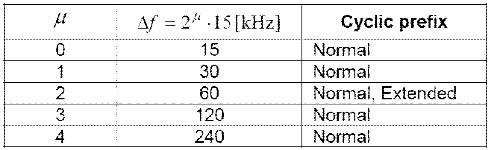
NR에서 프레임 구조를 살펴보면, 하향링크 및 상향링크 전송은 10ms 길이의 프레임으로 구성된다. 상기 프레임은 1ms 길이의 서브프레임이 10개 모여 구성될 수 있다. 이때, 각 서브프레임 별 연속하는 OFDM 심볼의 개수는  이다.
이다.
각 프레임은 2개의 동일한 크기를 갖는 하프-프레임(half frame)으로 구성될 수 있다. 이때, 각 하프-프레임은 각각 서브프레임 0 - 4 및 서브프레임 5- 9 로 구성될 수 있다.
부반송파 간격(subcarrier spacing) μ 에 대해, 슬롯은 하나의 서브프레임 내 오름차순으로  와 같이 넘버링되고, 하나의 프레임 내 오름차순으로
  와 같이 넘버링될 수 있다. 이때, 하나의 슬롯 내 연속하는 OFDM 심볼 개수 (
 )는 순환 전치에 따라 하기 표와 같이 결정될 수 있다. 하나의 서브프레임 내 시작 슬롯 (
 )은 동일한 서브프레임 내 시작 OFDM 심볼 (
 ) 과 시간 차원에서 정렬되어 있다 (aligned). 하기 표 4는 일반 순환 전치 (normal cyclic prefix)를 위한 슬롯별 / 프레임별/ 서브프레임별 OFDM 심볼의 개수를 나타내고, 표 5는 확장된 순환 전치 (extended cyclic prefix)를 위한 슬롯별 / 프레임별/ 서브프레임별 OFDM 심볼의 개수를 나타낸다.


본 발명이 적용 가능한 NR 시스템에서는 상기와 같은 슬롯 구조로써 자립적 슬롯 구조 (Self-contained slot structure)가 적용될 수 있다.
도 5는 본 발명에 적용 가능한 자립적 슬롯 구조 (Self-contained slot structure)를 나타낸 도면이다.
도 5에서 빗금친 영역 (예: symbol index =0)은 하향링크 제어 (downlink control) 영역을 나타내고, 검정색 영역 (예: symbol index =13)은 상향링크 제어 (uplink control) 영역을 나타낸다. 이외 영역 (예: symbol index = 1 ~ 12)은 하향링크 데이터 전송을 위해 사용될 수도 있고, 상향링크 데이터 전송을 위해 사용될 수도 있다.
이러한 구조에 따라 기지국 및 UE는 한 개의 슬롯 내에서 DL 전송과 UL 전송을 순차적으로 진행할 수 있으며, 상기 하나의 슬롯 내에서 DL 데이터를 송수신하고 이에 대한 UL ACK/NACK도 송수신할 수 있다. 결과적으로 이러한 구조는 데이터 전송 에러 발생시에 데이터 재전송까지 걸리는 시간을 줄이게 되며, 이로 인해 최종 데이터 전달의 지연을 최소화할 수 있다.
이와 같은 자립적 슬롯 구조에서 기지국과 UE가 송신 모드에서 수신모드로 전환 또는 수신모드에서 송신모드로 전환을 위해서는 일정 시간 길이의 타입 갭(time gap)이 필요하다. 이를 위하여 자립적 슬롯 구조에서 DL에서 UL로 전환되는 시점의 일부 OFDM 심볼은 가드 구간 (guard period, GP)로 설정될 수 있다.
앞서 상세한 설명에서는 자립적 슬롯 구조가 DL 제어 영역 및 UL 제어 영역을 모두 포함하는 경우를 설명하였으나, 상기 제어 영역들은 상기 자립적 슬롯 구조에 선택적으로 포함될 수 있다. 다시 말해, 본 발명에 따른 자립적 슬롯 구조는 도 8과 같이 DL 제어 영역 및 UL 제어 영역을 모두 포함하는 경우 뿐만 아니라 DL 제어 영역 또는 UL 제어 영역만을 포함하는 경우도 포함할 수 있다.
일 예로, 슬롯은 다양한 슬롯 포맷을 가질 수 있다. 이때, 각 슬롯의 OFDM 심볼은 하향링크 ('D'로 표기함), 플렉시블('X'로 표기함), 상향링크 ('U'로 표기함)로 분류될 수 있다.
따라서, 하향링크 슬롯에서 UE는 하향링크 전송이 'D' 및 'X' 심볼들에서만 발생한다고 가정할 수 있다. 이와 유사하게, 상향링크 슬롯에서 UE는 상향링크 전송이 'U' 및 'X' 심볼에서만 발생한다고 가정할 수 있다.
이하에서는 아날로그 빔포밍 (Analog beamforming)에 대하여 설명한다.
밀리미터 파 (Millimeter Wave, mmW)에서는 파장이 짧아 동일 면적에 다수개의 안테나 요소(element)의 설치가 가능하다. 즉, 30GHz 대역에서 파장은 1cm이므로, 5 * 5 cm의 패널(panel)에 0.5 lambda(파장) 간격으로 2-차원 (2-dimension) 배열을 하는 경우 총 100개의 안테나 요소를 설치할 수 있다. 이에 따라, 밀리미터 파 (mmW)에서는 다수개의 안테나 요소를 사용하여 빔포밍 (beamforming, BF) 이득을 높여 커버리지를 증가시키거나, 쓰루풋 (throughput)을 높일 수 있다.
이때, 안테나 요소 별로 전송 파워 및 위상 조절이 가능하도록 각 안테나 요소는 TXRU(Transceiver Unit)을 포함할 수 있다. 이를 통해, 각 안테나 요소는 주파수 자원 별로 독립적인 빔포밍을 수행할 수 있다.
그러나 100여개의 안테나 요소 모두에 TXRU를 설치하기에는 가격측면에서 실효성이 떨어지는 문제를 갖게 된다. 그러므로 하나의 TXRU에 다수개의 안테나 요소를 매핑하고 아날로그 위상 시프터 (analog phase shifter)로 빔(beam)의 방향을 조절하는 방식이 고려되고 있다. 이러한 아날로그 빔포밍 방식은 전 대역에 있어서 하나의 빔 방향만을 만들 수 있어 주파수 선택적 빔포밍이 어렵다는 단점을 갖는다.
이에 대한 해결 방안으로, 디지털 빔포밍과 아날로그 빔포밍의 중간 형태로 Q개의 안테나 요소보다 적은 개수인 B개의 TXRU를 갖는 하이브리드 빔포밍 (hybrid BF)를 고려할 수 있다. 이 경우에 B개의 TXRU와 Q개의 안테나 요소의 연결 방식에 따라서 차이는 있지만, 동시에 전송할 수 있는 빔(beam)의 방향은 B개 이하로 제한될 수 있다.
도 6 및 도 7은 TXRU와 안테나 요소 (element)의 대표적인 연결 방식을 나타낸 도면이다. 여기서 TXRU 가상화 (virtualization) 모델은 TXRU의 출력 신호와 안테나 요소의 출력 신호의 관계를 나타낸다.
도 6은 TXRU가 서브 어레이 (sub-array)에 연결된 방식을 나타낸 도면이다. 도 6의 경우, 안테나 요소는 하나의 TXRU에만 연결된다.
반면, 도 7은 TXRU가 모든 안테나 요소에 연결된 방식을 나타낸 도면이다. 도 7의 경우, 안테나 요소는 모든 TXRU에 연결된다. 이때, 안테나 요소가 모든 TXRU에 연결되기 위하여 도 8에 도시된 바와 같이 별도의 덧셈기를 필요로 한다.
도 6 및 도 7에서, W는 아날로그 위상 시프터 (analog phase shifter)에 의해 곱해지는 위상 벡터를 나타낸다. 즉, W는 아날로그 빔포밍의 방향을 결정하는 주요 파라미터이다. 여기서 CSI-RS 안테나 포트와 TXRU들과의 매핑은 1:1 또는 1:다(多) (1-to-many) 일 수 있다.
도 6의 구성에 따르면, 빔포밍의 포커싱이 어려운 단점이 있으나, 전체 안테나 구성을 적은 비용으로 구성할 수 있다는 장점이 있다.
도 7의 구성에 따르면, 빔포밍의 포커싱이 쉽다는 장점이 있다. 다만, 모든 안테나 요소에 TXRU가 연결되는 바, 전체 비용이 증가한다는 단점이 있다.
본 발명이 적용 가능한 NR 시스템에서 복수의 안테나가 사용되는 경우, 디지털 빔포밍 (Digital beamforming) 및 아날로그 빔포밍 (Analog beamforming)을 결합한 하이브리드 빔포밍 (Hybrid beamforming) 기법이 적용될 수 있다. 이때, 아날로그 빔포밍 (또는 RF (Radio Frequency) 빔포밍)은 RF 단에서 프리코딩 (또는 콤바이닝 (Combining))을 수행하는 동작을 의미한다. 그리고, 하이브리드 빔포밍에서 베이스밴드 (Baseband) 단과 RF 단은 각각 프리코딩 (또는 콤바이닝)을 수행한다. 이로 인해 RF 체인 수와 D/A (Digital-to-Analog) (또는 A/D (Analog-to-Digital) 컨버터 수를 줄이면서도 디지털 빔포밍에 근접하는 성능을 낼 수 있다는 장점이 있다.
설명의 편의상, 상기 하이브리드 빔포밍 구조는 N개 송수신단 (Transceiver unit, TXRU)과 M개의 물리적 안테나로 표현될 수 있다. 이때, 송신단에서 전송할 L개 데이터 계층 (Data layer)에 대한 디지털 빔포밍은 N * L (N by L) 행렬로 표현될 수 있다. 이후 변환된 N개 디지털 신호는 TXRU를 거쳐 아날로그 신호로 변환되고, 상기 변환된 신호에 대해 M * N (M by N) 행렬로 표현되는 아날로그 빔포밍이 적용된다.
도 8은 TXRU 및 물리적 안테나 관점에서의 하이브리드 빔포밍 구조를 간단히 나타낸 도면이다. 이때, 상기 도 8에서 디지털 빔의 개수는 L개이며, 아날로그 빔의 개수는 N개이다.
추가적으로, NR 시스템에서는 기지국이 아날로그 빔포밍을 심볼 단위로 변경할 수 있도록 설계하여 특정한 지역에 위치한 단말에게 보다 효율적인 빔포밍을 지원하는 방법을 고려하고 있다. 더 나아가, 도 8과 같이 특정 N개의 TXRU와 M개의 RF 안테나를 하나의 안테나 패널(panel)로 정의할 때, 본 발명에 따른 NR 시스템에서는 서로 독립적인 하이브리드 빔포밍이 적용 가능한 복수의 안테나 패널을 도입하는 방안까지 고려되고 있다.
상기와 같이 기지국이 복수의 아날로그 빔을 활용하는 경우, 단말 별로 신호 수신에 유리한 아날로그 빔이 다를 수 있다. 이에 따라, 본 발명이 적용 가능한 NR 시스템에서는 기지국이 특정 서브프레임 (SF) 내에서 심볼 별로 상이한 아날로그 빔을 적용하여 (적어도 동기 신호, 시스템 정보, 페이징 (Paging) 등) 신호를 전송함으로써 모든 단말이 수신 기회를 가질 수 있도록 하는 빔 스위핑 (Beam sweeping) 동작이 고려되고 있다.
LTE와 같은 통신 시스템에서는, 셀 간 간섭 측정을 위해 ZP CSI-RS 기반의 IMR(interference measurement resource)이 사용되었다. 이는 기존 ZP CSI-RS로 지정할 수 있는 자원 중 하나를 지정하여 해당 자원에서 측정한 간섭을 CSI 도출에 사용하는 방식이다. CoMP(coordinated multiple point transmission and reception)와 같은 환경에서 해당 IMR에서 측정하는 간섭은, CoMP 집합 내의 eNB간에 상정한 CoMP 시나리오에 대한 간섭을 해당 IMR에서 측정하도록 기지국 간 레이트 매칭(rate matching) 등을 통해 조율할 수 있다.
이와 같은 간섭 측정 방식은 타 기지국의 데이터 전송을 간섭으로서 측정하는 것을 상정하고 있기 때문에 제한이 발생한다. 예를 들어, MU(mutiple user) 시나리오와 같은 상황을 고려한다면 기지국이 고려해야 할 간섭 가정(hypothesis)이 크게 늘어나기 때문에 IMR의 설정(configuration) 측면에서 어려움이 생긴다. 이를 위해, 뉴랫과 같은 통신 시스템에서는, 간섭 측정을 위한 간섭 자원(IMR)으로서 NZP CSI-RS 기반 IMR이 고려되고 있다. 이와 같은 IMR은 기지국이 상정하는 간섭을 NZP CSI-RS를 사용하여 에뮬레이션(emulation)하여 단말에게 전송하는 방식으로, 여러 가지 간섭 상황을 더 적은 설정 자원을 사용하여 측정할 수 있다.
상술한 NZP CSI-RS 기반 IMR을 좀 더 적은 자원 설정으로 사용하는 방식으로, 포트-와이즈 간섭 측정(port-wise interference measurement) 방식을 고려할 수 있다. 기지국은 하나의 IMR 내에서 각 포트 별로 간섭을 다르게 전송하고, 또한 단말은 이를 인지하고 각 포트 별로 서로 다른 간섭 상황을 가정하여 CSI를 계산/보고할 수 있다. 이 방식으로 자원의 오버헤드를 줄일 수 있다. 예를 들어, 2-포트 IMR을 기준으로 했을 때, 2 CDMed(code division multiplexed) 포트를 사용하는 포트-와이즈 IMR과 2 개의 2-RE NZP CSI-RS 기반 IMR은, 자원의 사용 측면에서 2배의 차이를 보일 수 있다.
이를 위해, 기지국은 단말에 포트-와이즈 IMR(이하, PIMR)을 설정해 줄 수 있다. 이는 다른 IMR과 달리 간섭 가정이 각 포트별로 다르기 때문에, 단말은 이를 인지하고 IMR 내 각 포트에 대해 독립적으로 간섭 측정을 수행한다. 다른 IMR과 구분하기 위해, IMR 타입 지시자를 IMR 설정에 포함하여 해당 IMR이 ZP CSI-RS 기반 IMR인지, NZP CSI-RS 기반 IMR인지, 혹은 PIMR인지 알려줄 수 있다. 혹은 CSI를 위한 RS 타입 지시자(RS type for CSI indicator)를 포함시켜, 채널 측정을 위한 NZP CSI-RS 인지의 정보를 포함하여 설정해 줄 수 있다. 이와 같은 RS 타입 지시자는 RRC 시그널링을 통해 단말에게 설정될 수 있다.
이하에서는 설명의 편의를 위해 3GPP 뉴랫 시스템을 기반으로 제안 방식을 설명한다. 하지만, 제안 방식이 적용되는 시스템의 범위는 3GPP 뉴랫 시스템 외에 다른 시스템(예컨대, LTE, UTRA 등)으로도 확장 가능하다. 또한 본 특허에서 기술하는 기지국의 명칭은 셀, 기지국, eNB, gNB, 섹터, 전송 포인트(TP), 수신 포인트(RP), 원격 라디오 헤드(remote radio head; RRH), 릴레이 등의 송수신 포인트에 적용되며, 특정 송수신 포인트에서 요소 반송파(component carrier; CC)를 구분하기 위한 포괄적인 용어로 사용된다.
위 PIMR을 사용한 CSI 계산은 아래와 같이 수행할 수 있다.
Alt 1: 각 포트에서 측정된 간섭의 합을 하나의 간섭으로 간주하여 CSI 계산.
단말은 CSI를 계산하기 위해, 각 포트 별로 측정된 간섭의 측정 결과를 합하여 하나의 간섭으로 간주하고, 이와 같이 합산된 간섭에 대해 수신기 필터를 선택하여 CSI를 계산 및 보고한다. 예를 들어, 4-포트 PIMR이 단말에게 설정되었을 경우, 단말은 각 포트에서 측정된 4개의 간섭 I1, I2, I3, I4의 합인 (I1+I2+I3+I4)를 실제 간섭으로 간주하여 수신기 필터를 선택 및 CSI를 계산 및 보고할 수 있다.
특히 이와 같은 경우, 기지국은 단말 동작과 무관하게 각 포트 별로 간섭 에뮬레이션을 수행할 수 있다. 예를 들어, 기지국이 특정 포트에 간섭을 제공하지 않아도 단말은 전체 간섭을 측정할 수 있다. 만약 I1, I2, I3, I4 중 I3=0으로, 3번째 포트에서 기지국이 간섭 에뮬레이션을 하지 않더라도, 단말 측면에서는 투명(transparent)하게 동작할 수 있다.
자원을 더욱 절약하기 위해, 별도로 ZP CSI-RS를 IMR로서 두는 대신 PIMR 내에 ZP IMR 포트를 설정하고, 해당 포트를 'ZP IMR 포트'로서 사용할 수 있다. 다시 말해, ZP IMR 포트에서는 기지국에서 PIMR의 각 포트에서 공통으로 측정되는 셀-간 간섭만이 측정될 수 있도록 하고, 단말은 각 포트에서 측정된 에뮬레이션된 간섭 및 셀-간 간섭을 고려한 CSI를 계산할 수 있다. 특히 CDM된 IMR 포트를 사용할 경우, 측정한 셀-간 간섭(특히, 잡음)은 실제 데이터가 겪는 것과 동일한 것이 유리하므로, ZP IMR 포트는 왈쉬 코드(Walsh code) {+1, +1}을 사용하는 포트로 한정할 수 있다. 이와 같은 포트는 일반적으로 가장 낮은 포트 번호를 가지므로, ZP IMR 포트는 가장 낮은 인덱스를 갖는 포트로 한정할 수 있다. 단말은 이와 같은 ZP IMR 포트에서는 NZP CSI-RS에서 사용되는 시퀀스를 사용하지 않고, LTE의 ZP CSI-RS에서 측정한 방식과 동일한 방식으로 간섭을 측정한다. 이와 같이 ZP IMR 포트에서 측정된 간섭/잡음은 다른 포트에서 측정한 간섭에 더해 CSI를 계산하는데 사용한다.
PIMR은 동일한 RE 패턴에서 CDM으로 구분되는 포트들만으로 구성할 수 있다. 이와 같은 방식을 사용할 경우, 기지국이 에뮬레이션하고자 하는 간섭의 수에 상관 없이(하지만, 최대 포트 수보다는 작아야 한다.) 자원 설정 측면에서는 변동이 없기 때문에 유리하다. 예를 들어, 만약 2 RE, 길이-2 CDM을 사용하는 IMR 내의 두 포트가 왈쉬 코드 {+1, +1}과 {+1, -1}로 구분되고, 각 포트에 대해 기지국은 서로 다른 간섭을 에뮬레이션해서 전송할 때, 각 포트에서 에뮬레이션하여 전송하는 간섭을 각각 I1, I2, 그리고 각 PIMR 포트에서 공통으로 측정되는 잡음을 n이라 했을 때, 이는 도 9, 10, 11에 도시된 것과 같이 동작할 수 있다.
왈쉬 코드 {+1, +1}을 사용하는 IMR 포트의 경우, I2가 제거되어 I1 + 잡음이 측정될 수 있다. 또한, 왈쉬 코드 {+1, -1}을 사용하는 IMR 포트의 경우, I1과 잡음이 제거되어 I2가 측정될 수 있다.
따라서 각 포트에서 측정된 결과는 기지국이 의도한 I1 및 I2가 된다.
각 RE에서 동일하게 측정되는 잡음 n 대신 서로 다른 잡음이 측정되는 경우(예컨대, 측정의 부정확)에도 유사하게 동작할 수 있다. 도 12 및 13은 이러한 동작을 도시한다.
이와 같은 경우, 각 RE에서 측정된 잡음 n1, n2가 가우시안 잡음(Gaussian noise)과 같이 서로 독립적일 경우, 이 잡음의 합 또는차는 유사한 성격을 갖는 새로운 잡음 n3와 같이 간주될 수 있고, 이는 단순히 측정시 간섭이 일부 포함된 형태와 같이 다루어질 수 있다. 다시 말해, CDM 포트에서 측정된 간섭들은 개별 포트에서 측정된 간섭과 동일한 형태를 이룬다. 이와 같이 CDM 포트를 사용한 PIMR의 경우는 NZP CSI-RS를 이용한 간섭 에뮬레이션시 CDM, 특히 CDM-T(time, 시간 방향의 CDM)를 통해 다른 CSI-RS 포트의 전력을 빌려와 부스트(boost)할 수 있으므로, 잡음 대비 전력을 키워 좀 더 정확한 간섭의 에뮬레이션/측정이 가능하다.
Alt 2: 각 포트에서 측정된 간섭을 각각의 독립된 간섭 가정으로 가정하여 CSI 계산/보고
PIMR의 설정 방식 및 기지국이 각 포트에서 서로 다른 간섭을 에뮬레이션해서 전송하는 것은 상기 Alt 1과 동일하나, 이 경우 단말은 해당 PIMR의 간섭들을 합하지 않고, 독립된 간섭 가정으로서 간주하여 CSI를 계산한다. 특히 이와 같은 경우, 단말이 전송된 PIMR 포트 중 어떤 포트의 간섭을 실제 CSI를 계산 및/또는 보고하는데 사용할 지 결정하는 방식을 아래와 같이 나눌 수 있다.
Alt 2-1: 각 포트의 간섭 가정 중 가장 좋은
CQI를
보이는 포트 인덱스를 보고
이는 MU 스케줄링을 위해, 단말로 하여금 후보 MU 페어를 결정하도록 하고자 할 때 사용할 수 있다. 단말은 각 PIMR 포트에서 주어지는 간섭 중 가장 좋은 CQI를 만드는 간섭을 보이는 포트 인덱스를 기지국에 보고한다. 이는 다른 CSI와 함께 계산 및 보고할 수 있고, 특히 CQI와 같이 보고될 수 있다.
주기적 보고를 하는 상황에서 만약 CQI와 PIMR 포트 인덱스(PPI)만 전송되고 PMI는 반드시 같은 시점에 보고되지 않을 경우, 단말은 가장 최근에 계산/보고된 PMI을 기반으로 해당 CQI 및 PPI를 계산 및/또는 보고한다.
주기적 보고를 하는 상황에서 만약 CQI와 PPI가 반드시 같은 시점에 보고되지 않을 경우, CQI는 가장 최근에 보고한 PPI에 해당하는 IMR 포트에서 측정된 간섭을 기반으로 계산 및/또는 보고될 수 있다.
Alt 2-2: 기지국이 지정한 포트들에서 측정된 간섭을 사용하여 CSI 계산/보고
이 방식은 해당 PIMR이 복수의 단말들 간에 공유되고, 각 포트 마다 특정 단말(그룹)을 위한 에뮬레이트된 간섭이 전송되는 경우에 사용할 수 있다. 이와 같은 경우, 기지국은 포트 인덱스(들)을 DCI를 통해 단말에게 전송하고, 단말은 해당 인덱스들의 포트에서 측정되는 간섭을 사용하여 CSI를 계산 및/또는 보고할 수 있다. 특히 기지국이 복수의 포트 인덱스(들)을 사용할 경우, 단말은 지정된 모든 포트에서 전송되는 간섭을 합하여 하나의 간섭으로 간주하고 CSI를 계산 및/또는 보고할 수 있다. 이와 같은 포트 인덱스(들)은 비주기적 CSI 요청과 조인트 인코딩되어 전송될 수 있다.
Alt 2-3: 타깃
CQI를
정해 놓고, 해당
CQI를
만족하는 간섭 레벨을 보이는 포트
인덱스(들)을
기지국에 보고
단말은 주어진 PIMR의 각 포트에서 측정된 간섭 중, 타깃 CQI를 만족하는 간섭을 보이는 포트 인덱스(들)을 기지국에 보고할 수 있다. 특히 복수의 포트 인덱스들을 보고할 경우, 상기 복수의 포트 인덱스들에 대응하는 포트들에 대해, 1) 각 포트의 간섭을 가정하여 도출한 개별 CQI가 타깃 CQI를 초과함, 2) 각 포트의 간섭 합을 하나의 간섭으로 가정하여 도출한 CQI가 타깃 CQI를 초과함을 의미할 수 있다.
2)와 같은 경우는 타깃 CQI를 만족하는 간섭 포트의 숫자로, 특히 이와 같은 경우, 가장 많은 포트를 조합하는 경우를 우선하여 기지국에 보고할 수 있다. 이와 같은 경우는, 포트 인덱스 대신 비트맵으로 타깃 CQI를 위해 조합할 수 있는 포트 그룹을 기지국에 보고할 수 있고, 이는 비주기적 CSI 피드백으로 한정할 수 있다.
비트맵을 보고하는 것은 오버헤드가 크므로, 보고를 간소화하기 위해 간섭의 조합을 한정할 수 있다. 한 방식으로, PIMR의 각 포트에서 간섭 후보를 전송하되, 가장 낮은 포트 인덱스로부터 차례로 첫번째 간섭, 두번째 간섭, … 등과 같은 형식으로 전송되며, 단말은 각각의 포트에서 전송되는 간섭을 차례로 합하여, 그 중 타깃 CQI를 만족하는 포트의 개수를 보고할 수 있다. 예를 들어 기지국이 단말에게 4-포트 PIMR을 설정해 주었을 경우, 단말은 지정된 PIMR에서 간섭 없음/1개 간섭 포트(첫번째 포트에서 전송된 간섭)/ 2개 간섭 포트(첫번째 및 두번째 포트에서 전송된 간섭) / 3개 간섭 포트(첫번째, 두번째 그리고 세번째 포트에서 전송된 간섭)의 4가지 중 하나를 기지국에 보고할 수 있다.
유사하게, 기지국은 CQI의 견딜수 있는(tolerable) CQI 드롭을 단말에 알려줄 수 있다. 기지국은 SU CQI 대비 MU CQI의 네트워크-측면 스루풋 증가량을 어느 정도 예측할 수 있으므로, 기지국은 네트워크 측면에서 이익이 되는 수준으로 감당 가능한 CQI의 견딜수 있는 CQI 드롭을 단말에게 알려줄 수 있고, 단말은 (가장 최근에 보고된) SU CQI 대비 해당 견딜수 있는 CQI 드롭을 만족하는 범위 내의 간섭을 보이는 포트 인덱스(들)을 기지국에 보고할 수 있다. 이 때 단말은 실제 CQI의 감소량(즉, CQI 드롭)을 함께 계산하여 보고할 수 있다.
상기 타깃 CQI 혹은/그리고 최대 CQI 드롭은 기지국이 단말에게 시그널링해 줄 수 있다. 이는 RRC 등의 시그널링을 통해 보고 세팅(reporting setting)에 포함될 수 있고, 만약 비주기적 CSI 보고에 사용한다면 DCI를 통해 단말에게 시그널링해 줄 수 있다.
Alt 2-4: 각 포트에서 측정된 간섭을 각각의 독립된 간섭 가정으로 가정하여 각 IMR 포트에 대한 CSI를 전부 계산/보고 (c.f. 앞의 Alt 들은 일부
IMR
포트에 대해서만 보고했음)
이 방식은 기지국으로 하여금 MU 후보 중 적합한 단말에 대한 MU 스케줄링을 하기 위해 단말로 하여금 가능한 간섭에 대한 CSI를 모두 측정 및/또는 보고하도록 하는 방식이다. 이와 같이 전체 CSI를 보고하기 위해서는 큰 페이로드가 필요하기 때문에, 이와 같은 방식은 비주기적 보고와 같이 큰 페이로드를 사용하는 방식에 한정하여 사용할 수 있다.
혹은 주기적 보고에 사용할 경우, 롱(long) PUCCH 동작에만 사용할 수 있고, 숏(short) PUCCH에서는 사용하지 않을 수 있다. 이와 같은 경우, 다른 보고 방식(예컨대, 기존 CSI 보고 방법이나 Alt 2-1)을 같이 사용할 수 있는데, 이 경우 사용되는 다른 보고 방식은 숏 PUCCH를 사용하여 보고하여 피드백 오버헤드를 줄일 수 있다. 또한 유사한 목적으로, 본 방식(즉, Alt 2-4)은 상대적으로 더 긴 주기로, 다른 보고 방식(예컨대, 기존 CSI 보고 방법이나 Alt 2-1)은 상대적으로 더 짧은 주기로 보고할 수 있다.
본 특허에서 설명하는 PIMR의 설정을 위해, 기지국은 아래와 같은 정보의 일부 혹은 전부를 포함하는 설정을 RRC와 같은 상위 계층 시그널링을 통해 단말에게 설정해 줄 수 있다.
1. RE 패턴
A. 자원의 설정
2. CDM 길이/방향, 예컨대, {CDM-F(즉, 주파수 방향의 CDM), 길이-2}, {CDM-TF(즉, 시간 및 주파수 방향의 CDM), 길이-4}
A. 상술한 바와 같이, 특정 CDM, 예컨대, CDM-F 길이-2만을 사용할 수 있고, 이와 같은 경우 별도의 설정이 필요하지 않다. 특히 특정 CDM만이 고려될 경우, CDM 온/오프와 같은 방식으로 간략화될 수 있다.
B. 동일한 CDM 그룹 내에 속해 있는 포트로 한정하는 경우, CDM 길이/방향은 상기 RE 패턴과 일치하기 때문에, 이와 같은 설정은 생략될 수 있다.
3. 주파수 그래뉴러리티(Frequency granularity)
A. 광대역/부분 대역(대역폭 파트)에 대한 PIMR을 설정해 줄 수 있다.
i. 서로 다른 뉴머럴로지(numerology)를 가지는 대역폭 파트의 경우, 서로 다른 PIMR을 설정해 주는 것이 바람직하다.
ii. 특히, 하나의 대역폭 파트 내에서 더욱 작은 크기를 가지는 PIMR이 전송될 수 있고, 이를 위해 별도의 대역 설정(예컨대, 시작 RB 인덱스 및 길이)가 포함될 수 있다.
iii. 별도의 설정이 없이, CSI를 계산할 NZP CSI-RS를 따를 수 있다.
4. 포트 별 주파수 자원
A. 주파수 그래뉴러리티와 별도로, 각 포트 별로 간섭을 측정할 주파수 영역을 설정해 줄 수 있다. 이와 같은 경우, 각 포트 별 간섭을 합산할 때, 각 주파수 영역(예컨대, RB)에서 측정할 포트 별 간섭은 각 포트의 주파수 영역 설정에 따르고, 만약 포트 별 간섭을 합산하는 등 포트 간 동작을 수행할 경우, 해당 주파수 영역에서 측정하도록 설정된 포트에 대해서만 해당 동작을 수행할 수 있다.
5. 타이밍 동작(Timing behavior)
A. 해당 PIMR이 비주기적/반-지속적(semi-persistent)/주기적 인지 설정한다.
i. 반-지속적 혹은 주기적일 경우, 주기를 설정해줄 수 있다.
B. 만약 PIMR은 비주기적 IMR로 한정할 경우 별도의 주기 설정은 사용되지 않을 수 있다. 이와 같은 경우, DCI를 통해 해당 자원에서 간섭을 측정할 타이밍을 지정해 줄 수 있고, 이는 비주기적 CSI 요청과 함께 조인트 인코딩될 수 있다.
C. 주기가 포트 별로 설정될 수 있고, 이는 PIMR의 전송과 무관하게 단말이 각 포트에서 단말이 실제로 간섭을 측정해야 하는 주기를 지정해 줄 수 있다.
6. QCL(quasi-co-located)
A. 전송하는 TRP에 따라 서로 다른 간섭을 가정할 수 있으므로, 이를 판단하기 위한 QCL 파라미터를 포함할 수 있고, 단말이 간섭을 측정할 수신기 빔을 판단하기 위해 이 중 공간 QCL 파라미터(즉, 기지국의 전송 빔을 표현하는 RS, 예컨대 CSI-RS를 지시하여, 단말의 수신기 빔을 지시할 수 있음)를 적어도 포함할 수 있다.
B. 별도의 설정이 없이, CSI를 계산할 NZP CSI-RS를 따를 수 있다.
7. 시간-와이즈 MR(measurement restriction)
A. 포트 설정이 동적으로 변할 수 있기 때문에, 언제나 MR on (즉, 서로 다른 타이밍에 측정된 간섭 측정 결과는 서로 다른 간섭으로 간주하여, 평균 등의 후가공을 함께 하지 않는다.)으로 간주한다. 이 경우 별도의 MR 설정을 두지 않을 수 있다.
B. 주기/반-지속적 PIMR의 경우, 포트-와이즈 측정 제한(measurement restriction; MR)을 설정해 줄 수 있다. 이는 각 포트 별로 다르게 MR on/off를 하는 동작이다.
i. 기존의 자원-와이즈 MR(즉, 같은 자원에서 측정된 간섭은 서로 평균 가능)에 더하여, 자원-와이즈 MR/포트-와이즈 MR/no MR의 3가지 MR 설정 중 하나를 단말에게 설정해 줄 수 있다.
이 경우, 자원-와이즈 MR off는 모든 포트에서 포트-와이즈 MR이 오프된 상태로 해석할 수 있다.
8. 주파수 MR
A. 안정적인 간섭의 측정을 위해, 각 간섭이 동일하다고 가정할 수 있는(다시 말해, 동일한 프리코딩이 걸려 있다고 가정할 수 있는) 주파수 자원 크기(예컨대, RBG(resource block group) 크기)를 설정해 줄 수 있다. 이는 단순하게 주파수 MR 온/오프의 시그널링으로서 설정될 수 있다.
각 간섭이 서로 다른 PRG 크기를 사용하는 경우를 가정하여, 주파수 MR 온/오프 혹은 MR 그룹 크기를 포트 별로 서로 다르게 설정해 줄 수 있다.
9. 에뮬레이트된 간섭 전력
A. 측정한 간섭 전력을 실제 CSI 계산에 사용할 때 어느 정도 보정하여 사용할지에 대한 설정이다.
위 설정의 설명 중 의미가 있는 부분에 포트-와이즈 설정을 별도로 서술해 놓았으나, 별도로 서술하지 않는 항목에 있어서도 포트 별로 서로 다른 설정을 해줄 수 있다.
특히, 더 높은 유연성을 위해, 단말에게 복수의 PIMR을 위와 같이 RRC 시그널링으로 설정해 주고 DCI로서 실제 간섭 측정에 사용할 PIMR을 지정해 줄 수 있다. DCI의 오버헤드를 줄이기 위해, MAC 시그널링을 통해 DCI로 지정해 줄 PIMR의 집합을 선택해 주거나, PIMR의 선택을 위한 DCI 시그널링 없이 MAC 시그널링을 통해 PIMR을 선택해 줄 수 있다.
PIMR에 더하여, 하나의 자원 내에서 포트마다 별도의 역할을 부여할 수 있다. 다시 말해, 상술한 NZP-기반 IM 포트에 더해, 각 포트 마다 CMR(즉, 채널 측정을 위한 포트) 혹은/그리고 NZP-기반 IM 포트 혹은/그리고 ZP IMR 포트 등으로 나눌 수 있고, 이를 하나의 자원 내에서 설정해 줄 수 있다. 이와 같은 자원 내 포트 설정은 RRC와 같은 상위 계층 시그널링을 통해 기지국이 단말에게 설정해 줄 수 있다.
본 기술에서 정의되는 PIMR 내 '포트'는 IMR 내에서 정의되는 일종의 자원 그룹 단위로, 예를 들어 동일한 구조(즉, IMR의 포트 수(혹은 하나의 IMR에 포함되는 RB 당 RE의 수), 주파수/시간-와이즈 RE 위치, CDM 패턴)의 NZP CSI-RS가 가지는 포트 구성과 동일한 설정을 가질 수 있다. 만약 기지국이 간섭을 더욱 정확하게 측정하기 위해 일정 포트 그룹 단위로 간섭을 측정하도록 확장할 수 있고, 이를 위해 단말에게 해당 포트 그룹핑에 대한 시그널링 또는 설정을 줄 수 있다. 예를 들어, 기지국은 포트 그룹에 포함되는 포트 인덱스를 RRC와 같은 상위-계층 시그널링으로 설정해 줄 수 있고, 혹은 단순하게 각 포트 그룹 내에 속할 포트의 수(예컨대, 1, 2, 4 포트)를 상위-계층 시그널링으로 설정해 주는 것으로 가장 낮은 번호의 포트부터 설정받은 수만큼의 PIMR 포트를 해당 포트 그룹에 포함된다고 간주할 수 있다. 이와 같은 경우 단말은 해당 포트 그룹 내에서는 서로 같은 가정에 대한 간섭이 전송되었다고 간주하고 간섭을 측정(예컨대, 평균하여 간섭을 측정)할 수 있다.
도 14는 본 발명의 실시예들을 수행하는 전송장치(10) 및 수신장치(20)의 구성요소를 나타내는 블록도이다. 전송장치(10) 및 수신장치(20)는 정보 및/또는 데이터, 신호, 메시지 등을 나르는 무선 신호를 전송 또는 수신할 수 있는 송신기/수신기(13, 23)와, 무선통신 시스템 내 통신과 관련된 각종 정보를 저장하는 메모리(12, 22), 상기 송신기/수신기(13, 23) 및 메모리(12, 22)등의 구성요소와 동작적으로 연결되어, 상기 구성요소를 제어하여 해당 장치가 전술한 본 발명의 실시예들 중 적어도 하나를 수행하도록 메모리(12, 22) 및/또는 송신기/수신기(13,23)을 제어하도록 구성된 프로세서(11, 21)를 각각 포함한다.
메모리(12, 22)는 프로세서(11, 21)의 처리 및 제어를 위한 프로그램을 저장할 수 있고, 입/출력되는 정보를 임시 저장할 수 있다. 메모리(12, 22)가 버퍼로서 활용될 수 있다. 프로세서(11, 21)는 통상적으로 전송장치 또는 수신장치 내 각종 모듈의 전반적인 동작을 제어한다. 특히, 프로세서(11, 21)는 본 발명을 수행하기 위한 각종 제어 기능을 수행할 수 있다. 프로세서(11, 21)는 컨트롤러(controller), 마이크로 컨트롤러(microcontroller), 마이크로 프로세서(microprocessor), 마이크로 컴퓨터(microcomputer) 등으로도 불릴 수 있다. 프로세서(11, 21)는 하드웨어(hardware) 또는 펌웨어(firmware), 소프트웨어, 또는 이들의 결합에 의해 구현될 수 있다. 하드웨어를 이용하여 본 발명을 구현하는 경우에는, 본 발명을 수행하도록 구성된 ASICs(application specific integrated circuits) 또는 DSPs(digital signal processors), DSPDs(digital signal processing devices), PLDs(programmable logic devices), FPGAs(field programmable gate arrays) 등이 프로세서(11, 21)에 구비될 수 있다. 한편, 펌웨어나 소프트웨어를 이용하여 본 발명을 구현하는 경우에는 본 발명의 기능 또는 동작들을 수행하는 모듈, 절차 또는 함수 등을 포함하도록 펌웨어나 소프트웨어가 구성될 수 있으며, 본 발명을 수행할 수 있도록 구성된 펌웨어 또는 소프트웨어는 프로세서(11, 21) 내에 구비되거나 메모리(12, 22)에 저장되어 프로세서(11, 21)에 의해 구동될 수 있다.
전송장치(10)의 프로세서(11)는 상기 프로세서(11) 또는 상기 프로세서(11)와 연결된 스케줄러로부터 스케줄링되어 외부로 전송될 신호 및/또는 데이터에 대하여 소정의 부호화(coding) 및 변조(modulation)를 수행한 후 송신기/수신기(13)에 전송한다. 예를 들어, 프로세서(11)는 전송하고자 하는 데이터 열을 역다중화 및 채널 부호화, 스크램블링, 변조과정 등을 거쳐 K개의 레이어로 변환한다. 부호화된 데이터 열은 코드워드로 지칭되기도 하며, MAC 계층이 제공하는 데이터 블록인 전송 블록과 등가이다. 일 전송블록(transport block, TB)은 일 코드워드로 부호화되며, 각 코드워드는 하나 이상의 레이어의 형태로 수신장치에 전송되게 된다. 주파수 상향 변환을 위해 송신기/수신기(13)는 오실레이터(oscillator)를 포함할 수 있다. 송신기/수신기(13)는 Nt개(Nt는 1보다 이상의 양의 정수)의 전송 안테나를 포함할 수 있다.
수신장치(20)의 신호 처리 과정은 전송장치(10)의 신호 처리 과정의 역으로 구성된다. 프로세서(21)의 제어 하에, 수신장치(20)의 송신기/수신기(23)는 전송장치(10)에 의해 전송된 무선 신호를 수신한다. 상기 송신기/수신기(23)는 Nr개의 수신 안테나를 포함할 수 있으며, 상기 송신기/수신기(23)는 수신 안테나를 통해 수신된 신호 각각을 주파수 하향 변환하여(frequency down-convert) 기저대역 신호로 복원한다. 송신기/수신기(23)는 주파수 하향 변환을 위해 오실레이터를 포함할 수 있다. 상기 프로세서(21)는 수신 안테나를 통하여 수신된 무선 신호에 대한 복호(decoding) 및 복조(demodulation)를 수행하여, 전송장치(10)가 본래 전송하고자 했던 데이터를 복원할 수 있다.
송신기/수신기(13, 23)는 하나 이상의 안테나를 구비한다. 안테나는, 프로세서(11, 21)의 제어 하에 본 발명의 일 실시예에 따라, 송신기/수신기(13, 23)에 의해 처리된 신호를 외부로 전송하거나, 외부로부터 무선 신호를 수신하여 송신기/수신기(13, 23)로 전달하는 기능을 수행한다. 안테나는 안테나 포트로 불리기도 한다. 각 안테나는 하나의 물리 안테나에 해당하거나 하나보다 많은 물리 안테나 요소(element)의 조합에 의해 구성될 수 있다. 각 안테나로부터 전송된 신호는 수신장치(20)에 의해 더 이상 분해될 수 없다. 해당 안테나에 대응하여 전송된 참조신호(reference signal, RS)는 수신장치(20)의 관점에서 본 안테나를 정의하며, 채널이 일 물리 안테나로부터의 단일(single) 무선 채널인지 혹은 상기 안테나를 포함하는 복수의 물리 안테나 요소(element)들로부터의 합성(composite) 채널인지에 관계없이, 상기 수신장치(20)로 하여금 상기 안테나에 대한 채널 추정을 가능하게 한다. 즉, 안테나는 상기 안테나 상의 심볼을 전달하는 채널이 상기 동일 안테나 상의 다른 심볼이 전달되는 상기 채널로부터 도출될 수 있도록 정의된다. 복수의 안테나를 이용하여 데이터를 송수신하는 다중 입출력(Multi-Input Multi-Output, MIMO) 기능을 지원하는 송신기/수신기의 경우에는 2개 이상의 안테나와 연결될 수 있다.
본 발명의 실시예들에 있어서, 단말 또는 UE는 상향링크에서는 전송장치(10)로 동작하고, 하향링크에서는 수신장치(20)로 동작한다. 본 발명의 실시예들에 있어서, 기지국 또는 eNB는 상향링크에서는 수신장치(20)로 동작하고, 하향링크에서는 전송장치(10)로 동작한다.
상기 전송장치 및/또는 상기 수신장치는 앞서 설명한 본 발명의 실시예들 중 적어도 하나 또는 둘 이상의 실시예들의 조합을 수행할 수 있다.
이러한 제안들의 조합 중 하나로서, 본 발명의 또다른 일 실시예에 따른 무선 통신 시스템에서 간섭 측정을 수행하는 단말에 있어서, 송신기 및 수신기; 및 상기 송신기 및 수신기를 제어하도록 구성된 프로세서를 포함하되, 상기 프로세서는 포트-와이즈 간섭 측정 자원과 관련된 설정을 수신하고, 상기 포트-와이즈 간섭 측정 자원은 각 포트 별 독립적인 간섭 가정에 대응하고, 그리고 상기 포트-와이즈 간섭 측정 자원에서 각 포트 별로 간섭을 측정하고, 측정 결과를 보고하고, 상기 측정 결과는 타깃 채널 품질 지시자(channel quality indicator; CQI)를 초과하는 CQI를 갖는 포트의 인덱스를 포함할 수 있다.
상기 측정 결과는 복수의 포트의 인덱스를 포함하고, 상기 복수의 포트의 각각에 대한 간섭에 기반한 CQI가 상기 타깃 CQI를 초과할 수 있다.
또는, 상기 측정 결과는 상기 복수의 포트의 인덱스를 포함하고, 상기 복수의 포트에 대한 간섭의 총합에 기반하여 도출된 CQI가 상기 타깃 CQI를 초과할 수 있다.
또는, 상기 측정 결과는 복수 개의 포트 그룹의 인덱스 정보를 포함하고, 각 포트 그룹은 간섭의 총합에 기반하여 도출된 CQI가 상기 타깃 CQI를 초과하는 복수의 포트를 포함할 수 있다.
또한, 상기 프로세서는 CQI의 드롭과 관련된 정보를 수신하고, 그리고 상기 CQI 드롭을 만족하는 범위 내의 간섭이 측정된 포트의 인덱스를 보고할 수 있다.
상기 포트-와이즈 간섭 측정 자원과 관련된 설정은, 포트-와이즈 측정 제한(measurement restriction; MR)을 포함할 수 있다.
상기 포트-와이즈 간섭 측정 자원과 관련된 설정은, 각 간섭 측정 자원에 대해 각 포트가 채널 측정 포트, 넌-제로 전력(non zero power) 간섭 측정 포트 또는 제로 전력 간섭 측정 포트인지를 지시하는 정보를 포함할 수 있다.
상술한 바와 같이 개시된 본 발명의 바람직한 실시예들에 대한 상세한 설명은 당업자가 본 발명을 구현하고 실시할 수 있도록 제공되었다. 상기에서는 본 발명의 바람직한 실시예들을 참조하여 설명하였지만, 해당 기술 분야의 숙련된 당업자는 하기의 특허 청구의 범위에 기재된 본 발명을 다양하게 수정 및 변경시킬 수 있음을 이해할 수 있을 것이다. 따라서, 본 발명은 여기에 나타난 실시형태들에 제한되려는 것이 아니라, 여기서 개시된 원리들 및 신규한 특징들과 일치하는 최광의 범위를 부여하려는 것이다.
본 발명은 단말, 릴레이, 기지국 등과 같은 무선 통신 장치에 사용될 수 있다.
Claims (14)
- 무선 통신 시스템에서 포트-와이즈(port-wise) 간섭 측정 자원을 이용한 간섭 측정 및 보고 방법에 있어서,포트-와이즈 간섭 측정 자원과 관련된 설정을 수신하는 단계;상기 포트-와이즈 간섭 측정 자원은 각 포트 별 독립적인 간섭 가정에 대응하고, 그리고상기 포트-와이즈 간섭 측정 자원에서 각 포트 별로 간섭을 측정하고, 측정 결과를 보고하는 단계를 포함하고,상기 측정 결과는 타깃 채널 품질 지시자(channel quality indicator; CQI)를 초과하는 CQI를 갖는 포트의 인덱스를 포함하는 것을 특징으로 하는, 방법.
- 제1항에 있어서,상기 측정 결과는 복수의 포트의 인덱스를 포함하고, 상기 복수의 포트의 각각에 대한 간섭에 기반한 CQI가 상기 타깃 CQI를 초과하는 것을 특징으로 하는, 방법.
- 제1항에 있어서,상기 측정 결과는 상기 복수의 포트의 인덱스를 포함하고, 상기 복수의 포트에 대한 간섭의 총합에 기반하여 도출된 CQI가 상기 타깃 CQI를 초과하는 것을 특징으로 하는, 방법.
- 제1항에 있어서,상기 측정 결과는 복수 개의 포트 그룹의 인덱스 정보를 포함하고, 각 포트 그룹은 간섭의 총합에 기반하여 도출된 CQI가 상기 타깃 CQI를 초과하는 복수의 포트를 포함하는 것을 특징으로 하는, 방법.
- 제1항에 있어서, CQI의 드롭과 관련된 정보를 수신하는 단계; 및상기 CQI 드롭을 만족하는 범위 내의 간섭이 측정된 포트의 인덱스를 보고하는 단계를 포함하는 것을 특징으로 하는, 방법.
- 제1항에 있어서,상기 포트-와이즈 간섭 측정 자원과 관련된 설정은, 포트-와이즈 측정 제한(measurement restriction; MR)을 포함하는 것을 특징으로 하는, 방법.
- 제1항에 있어서,상기 포트-와이즈 간섭 측정 자원과 관련된 설정은, 각 간섭 측정 자원에 대해 각 포트가 채널 측정 포트, 넌-제로 전력(non zero power) 간섭 측정 포트 또는 제로 전력 간섭 측정 포트인지를 지시하는 정보를 포함하는 것을 특징으로 하는, 방법.
- 무선 통신 시스템에서 간섭 측정을 수행하는 단말에 있어서,송신기 및 수신기; 및상기 송신기 및 수신기를 제어하도록 구성된 프로세서를 포함하되,상기 프로세서는:포트-와이즈 간섭 측정 자원과 관련된 설정을 수신하고, 상기 포트-와이즈 간섭 측정 자원은 각 포트 별 독립적인 간섭 가정에 대응하고, 그리고상기 포트-와이즈 간섭 측정 자원에서 각 포트 별로 간섭을 측정하고, 측정 결과를 보고하고,상기 측정 결과는 타깃 채널 품질 지시자(channel quality indicator; CQI)를 초과하는 CQI를 갖는 포트의 인덱스를 포함하는 것을 특징으로 하는, 단말.
- 제8항에 있어서,상기 측정 결과는 복수의 포트의 인덱스를 포함하고, 상기 복수의 포트의 각각에 대한 간섭에 기반한 CQI가 상기 타깃 CQI를 초과하는 것을 특징으로 하는, 단말.
- 제8항에 있어서,상기 측정 결과는 상기 복수의 포트의 인덱스를 포함하고, 상기 복수의 포트에 대한 간섭의 총합에 기반하여 도출된 CQI가 상기 타깃 CQI를 초과하는 것을 특징으로 하는, 단말.
- 제8항에 있어서,상기 측정 결과는 복수 개의 포트 그룹의 인덱스 정보를 포함하고, 각 포트 그룹은 간섭의 총합에 기반하여 도출된 CQI가 상기 타깃 CQI를 초과하는 복수의 포트를 포함하는 것을 특징으로 하는, 단말.
- 제8항에 있어서,상기 프로세서는 CQI의 드롭과 관련된 정보를 수신하고, 그리고상기 CQI 드롭을 만족하는 범위 내의 간섭이 측정된 포트의 인덱스를 보고하는 것을 특징으로 하는, 단말.
- 제8항에 있어서,상기 포트-와이즈 간섭 측정 자원과 관련된 설정은, 포트-와이즈 측정 제한(measurement restriction; MR)을 포함하는 것을 특징으로 하는, 단말.
- 제8항에 있어서,상기 포트-와이즈 간섭 측정 자원과 관련된 설정은, 각 간섭 측정 자원에 대해 각 포트가 채널 측정 포트, 넌-제로 전력(non zero power) 간섭 측정 포트 또는 제로 전력 간섭 측정 포트인지를 지시하는 정보를 포함하는 것을 특징으로 하는, 단말.
Priority Applications (1)
| Application Number | Priority Date | Filing Date | Title |
|---|---|---|---|
| US16/636,564 US11246051B2 (en) | 2017-08-04 | 2018-08-03 | Method and apparatus for interference measurement in wireless communication system |
Applications Claiming Priority (2)
| Application Number | Priority Date | Filing Date | Title |
|---|---|---|---|
| US201762541112P | 2017-08-04 | 2017-08-04 | |
| US62/541,112 | 2017-08-04 |
Publications (1)
| Publication Number | Publication Date |
|---|---|
| WO2019027281A1 true WO2019027281A1 (ko) | 2019-02-07 |
Family
ID=65233987
Family Applications (1)
| Application Number | Title | Priority Date | Filing Date |
|---|---|---|---|
| PCT/KR2018/008827 WO2019027281A1 (ko) | 2017-08-04 | 2018-08-03 | 무선 통신 시스템에서 간섭 측정을 위한 방법 및 이를 위한 장치 |
Country Status (2)
| Country | Link |
|---|---|
| US (1) | US11246051B2 (ko) |
| WO (1) | WO2019027281A1 (ko) |
Cited By (1)
| Publication number | Priority date | Publication date | Assignee | Title |
|---|---|---|---|---|
| EP4213454A4 (en) * | 2020-09-30 | 2024-03-06 | Huawei Technologies Co., Ltd. | METHOD AND DEVICE FOR ASSIGNING REFERENCE SIGNALS |
Families Citing this family (1)
| Publication number | Priority date | Publication date | Assignee | Title |
|---|---|---|---|---|
| US11700046B2 (en) * | 2021-06-04 | 2023-07-11 | Qualcomm Incorporated | Beam failure avoidance based on detected interference |
Citations (5)
| Publication number | Priority date | Publication date | Assignee | Title |
|---|---|---|---|---|
| KR20110104103A (ko) * | 2009-01-12 | 2011-09-21 | 콸콤 인코포레이티드 | 채널 품질 표시(cqi)를 계산 및 리포팅하기 위한 방법 및 장치 |
| US20140056272A1 (en) * | 2011-04-22 | 2014-02-27 | China Academy Of Telecommunications Technology | Method, device, and system for reporting channel quality indicator |
| KR20140074341A (ko) * | 2011-09-26 | 2014-06-17 | 후아웨이 테크놀러지 컴퍼니 리미티드 | 간섭 제어 방법 및 장치 |
| KR20150082448A (ko) * | 2013-01-03 | 2015-07-15 | 인텔 코포레이션 | 개선된 채널 품질 정보 피드백 기술 |
| WO2016163841A1 (ko) * | 2015-04-10 | 2016-10-13 | 엘지전자(주) | 무선 통신 시스템에서 채널 상태 정보를 보고하기 위한 방법 및 이를 위한 장치 |
Family Cites Families (5)
| Publication number | Priority date | Publication date | Assignee | Title |
|---|---|---|---|---|
| WO2010151090A2 (ko) * | 2009-06-25 | 2010-12-29 | 엘지전자 주식회사 | 그룹자원할당에서 harq 피드백 채널 할당방법 |
| US9178583B2 (en) * | 2013-01-08 | 2015-11-03 | Samsung Electronics Co., Ltd. | Channel state information feedback design in advanced wireless communication systems |
| US9252854B2 (en) * | 2013-06-07 | 2016-02-02 | Industrial Technology Research Institute | User equipment having channel quality indicator feedback mechanism |
| US9735818B2 (en) * | 2013-10-28 | 2017-08-15 | Lg Electronics Inc. | Method and apparatus for cancelling interference and receiving signal in wireless communication system |
| US20180077551A1 (en) * | 2016-09-12 | 2018-03-15 | Intel IP Corporation | Emergency response for iot and/or m2m devices |
-
2018
- 2018-08-03 US US16/636,564 patent/US11246051B2/en active Active
- 2018-08-03 WO PCT/KR2018/008827 patent/WO2019027281A1/ko active Application Filing
Patent Citations (5)
| Publication number | Priority date | Publication date | Assignee | Title |
|---|---|---|---|---|
| KR20110104103A (ko) * | 2009-01-12 | 2011-09-21 | 콸콤 인코포레이티드 | 채널 품질 표시(cqi)를 계산 및 리포팅하기 위한 방법 및 장치 |
| US20140056272A1 (en) * | 2011-04-22 | 2014-02-27 | China Academy Of Telecommunications Technology | Method, device, and system for reporting channel quality indicator |
| KR20140074341A (ko) * | 2011-09-26 | 2014-06-17 | 후아웨이 테크놀러지 컴퍼니 리미티드 | 간섭 제어 방법 및 장치 |
| KR20150082448A (ko) * | 2013-01-03 | 2015-07-15 | 인텔 코포레이션 | 개선된 채널 품질 정보 피드백 기술 |
| WO2016163841A1 (ko) * | 2015-04-10 | 2016-10-13 | 엘지전자(주) | 무선 통신 시스템에서 채널 상태 정보를 보고하기 위한 방법 및 이를 위한 장치 |
Cited By (1)
| Publication number | Priority date | Publication date | Assignee | Title |
|---|---|---|---|---|
| EP4213454A4 (en) * | 2020-09-30 | 2024-03-06 | Huawei Technologies Co., Ltd. | METHOD AND DEVICE FOR ASSIGNING REFERENCE SIGNALS |
Also Published As
| Publication number | Publication date |
|---|---|
| US11246051B2 (en) | 2022-02-08 |
| US20210160718A1 (en) | 2021-05-27 |
Similar Documents
| Publication | Publication Date | Title |
|---|---|---|
| WO2017222329A1 (ko) | 무선 통신 시스템에서 채널 상태 보고를 위한 방법 및 이를 위한 장치 | |
| WO2019017753A1 (ko) | 무선 통신 시스템에서 채널 상태 보고를 위한 방법 및 이를 위한 장치 | |
| WO2016204546A1 (ko) | 비주기적 채널 상태 정보-참조 신호를 이용한 채널 상태 보고를 위한 방법 및 이를 위한 장치 | |
| WO2018056784A1 (ko) | 무선 통신 시스템에서 간섭 측정을 위한 방법 및 이를 위한 장치 | |
| WO2016126063A1 (ko) | 무선 통신 시스템에서 채널 상태 보고 방법 및 이를 위한 장치 | |
| WO2018030804A1 (ko) | 무선 통신 시스템에서 채널 상태 보고를 위한 방법 및 이를 위한 장치 | |
| WO2018026230A1 (ko) | 무선 통신 시스템에서 채널 상태 보고를 위한 방법 및 이를 위한 장치 | |
| WO2016144050A1 (ko) | 무선 통신 시스템에서 신호를 전송하기 위한 방법 및 이를 위한 장치 | |
| WO2018164452A1 (ko) | 무선 통신 시스템에서 하향링크 신호를 수신 또는 전송하기 위한 방법 및 이를 위한 장치 | |
| WO2016163819A1 (ko) | 채널 상태 보고를 위한 방법 및 이를 위한 장치 | |
| WO2018226039A2 (ko) | 무선 통신 시스템에서 하향링크 신호를 수신 또는 전송하기 위한 방법 및 이를 위한 장치 | |
| WO2018030714A1 (ko) | 무선 통신 시스템에서 채널 상태 보고를 위한 방법 및 이를 위한 장치 | |
| WO2016072712A2 (ko) | 채널과 관련된 피드백을 위한 방법 및 이를 위한 장치 | |
| WO2017105135A2 (ko) | 무선 통신 시스템에서 상향링크 참조 신호 전송 또는 수신 방법 및 이를 위한 장치 | |
| WO2017171516A1 (ko) | 무선 통신 시스템에서 상향링크 제어 정보의 전송 또는 수신 방법 및 이를 위한 장치 | |
| WO2016122197A1 (ko) | 상향링크 신호를 전송하기 위한 방법 및 이를 위한 장치 | |
| WO2017171307A1 (ko) | 비주기적 채널 상태 정보-참조 신호를 이용한 채널 상태 보고를 위한 방법 및 이를 위한 장치 | |
| WO2018128340A1 (ko) | 무선 통신 시스템에서 채널 상태 보고를 위한 방법 및 이를 위한 장치 | |
| WO2016018100A1 (ko) | 채널 상태 보고를 위한 방법 및 이를 위한 장치 | |
| WO2016024731A1 (ko) | 무선 통신 시스템에서 채널 상태 보고를 위한 방법 및 이를 위한 장치 | |
| WO2019143131A1 (ko) | 무선 통신 시스템에서 상향링크 신호를 송신하는 방법 및 장치 | |
| WO2016032219A1 (ko) | 무선 통신 시스템에서 참조 신호 수신 방법 및 이를 위한 장치 | |
| WO2012128505A2 (ko) | 장치-대-장치 통신 방법 및 장치 | |
| WO2018199681A1 (ko) | 무선 통신 시스템에서 채널 및 간섭 측정을 위한 방법 및 이를 위한 장치 | |
| WO2018021815A1 (ko) | 무선 통신 시스템에서 채널 상태 보고를 위한 방법 및 이를 위한 장치 |
Legal Events
| Date | Code | Title | Description |
|---|---|---|---|
| 121 | Ep: the epo has been informed by wipo that ep was designated in this application |
Ref document number: 18841626 Country of ref document: EP Kind code of ref document: A1 |
|
| NENP | Non-entry into the national phase |
Ref country code: DE |
|
| 122 | Ep: pct application non-entry in european phase |
Ref document number: 18841626 Country of ref document: EP Kind code of ref document: A1 |