WO2019026909A1 - 鋼部品の製造方法および鋼部品 - Google Patents
鋼部品の製造方法および鋼部品 Download PDFInfo
- Publication number
- WO2019026909A1 WO2019026909A1 PCT/JP2018/028676 JP2018028676W WO2019026909A1 WO 2019026909 A1 WO2019026909 A1 WO 2019026909A1 JP 2018028676 W JP2018028676 W JP 2018028676W WO 2019026909 A1 WO2019026909 A1 WO 2019026909A1
- Authority
- WO
- WIPO (PCT)
- Prior art keywords
- tempering
- steel
- quenching
- mass
- concentration
- Prior art date
- Legal status (The legal status is an assumption and is not a legal conclusion. Google has not performed a legal analysis and makes no representation as to the accuracy of the status listed.)
- Ceased
Links
Images



Classifications
-
- C—CHEMISTRY; METALLURGY
- C21—METALLURGY OF IRON
- C21D—MODIFYING THE PHYSICAL STRUCTURE OF FERROUS METALS; GENERAL DEVICES FOR HEAT TREATMENT OF FERROUS OR NON-FERROUS METALS OR ALLOYS; MAKING METAL MALLEABLE, e.g. BY DECARBURISATION OR TEMPERING
- C21D1/00—General methods or devices for heat treatment, e.g. annealing, hardening, quenching or tempering
- C21D1/06—Surface hardening
-
- C—CHEMISTRY; METALLURGY
- C21—METALLURGY OF IRON
- C21D—MODIFYING THE PHYSICAL STRUCTURE OF FERROUS METALS; GENERAL DEVICES FOR HEAT TREATMENT OF FERROUS OR NON-FERROUS METALS OR ALLOYS; MAKING METAL MALLEABLE, e.g. BY DECARBURISATION OR TEMPERING
- C21D7/00—Modifying the physical properties of iron or steel by deformation
- C21D7/02—Modifying the physical properties of iron or steel by deformation by cold working
- C21D7/04—Modifying the physical properties of iron or steel by deformation by cold working of the surface
- C21D7/06—Modifying the physical properties of iron or steel by deformation by cold working of the surface by shot-peening or the like
-
- C—CHEMISTRY; METALLURGY
- C21—METALLURGY OF IRON
- C21D—MODIFYING THE PHYSICAL STRUCTURE OF FERROUS METALS; GENERAL DEVICES FOR HEAT TREATMENT OF FERROUS OR NON-FERROUS METALS OR ALLOYS; MAKING METAL MALLEABLE, e.g. BY DECARBURISATION OR TEMPERING
- C21D9/00—Heat treatment, e.g. annealing, hardening, quenching or tempering, adapted for particular articles; Furnaces therefor
-
- C—CHEMISTRY; METALLURGY
- C21—METALLURGY OF IRON
- C21D—MODIFYING THE PHYSICAL STRUCTURE OF FERROUS METALS; GENERAL DEVICES FOR HEAT TREATMENT OF FERROUS OR NON-FERROUS METALS OR ALLOYS; MAKING METAL MALLEABLE, e.g. BY DECARBURISATION OR TEMPERING
- C21D9/00—Heat treatment, e.g. annealing, hardening, quenching or tempering, adapted for particular articles; Furnaces therefor
- C21D9/32—Heat treatment, e.g. annealing, hardening, quenching or tempering, adapted for particular articles; Furnaces therefor for gear wheels, worm wheels, or the like
-
- C—CHEMISTRY; METALLURGY
- C22—METALLURGY; FERROUS OR NON-FERROUS ALLOYS; TREATMENT OF ALLOYS OR NON-FERROUS METALS
- C22C—ALLOYS
- C22C38/00—Ferrous alloys, e.g. steel alloys
-
- C—CHEMISTRY; METALLURGY
- C22—METALLURGY; FERROUS OR NON-FERROUS ALLOYS; TREATMENT OF ALLOYS OR NON-FERROUS METALS
- C22C—ALLOYS
- C22C38/00—Ferrous alloys, e.g. steel alloys
- C22C38/06—Ferrous alloys, e.g. steel alloys containing aluminium
Definitions
- the present invention relates to a method of manufacturing steel parts and steel parts.
- Steel parts such as gears and bearings used in transmissions of automobiles are manufactured by processing parts using chromium steel or chromium molybdenum steel and performing carburizing, quenching and tempering.
- the demand for global warming prevention and resource saving through CO2 emission reduction is increasing, and weight reduction of a vehicle is called for further fuel efficiency improvement.
- steel parts are required to be miniaturized and load is increased, further strengthening is required.
- steel parts used in automobiles reach environmental temperatures up to about 300 ° C., the hardness of the surface of the steel parts may be reduced, and pitting failure may occur. For this reason, in order to improve the resistance to pitting fatigue, steel parts excellent in temper softening resistance are required.
- the hardness of a portion 50 ⁇ m deep from the surface of the steel part after “300 ° C. tempering” (hereinafter, referred to as “surface hardness”) has a Vickers hardness (hereinafter, referred to as “HV”). It is made to be 700 or more.
- the surface hardness of the steel component after tempering at 300 ° C. is made to be HV700 or more by using a steel material containing Si + 0.2Cr + 0.01Mo in excess of 1.3%.
- a steel containing an appropriate amount of Si, Mn, Cr, Mo, etc. is formed into a part shape, and the hardness after carburizing, tempering or carbonitriding, tempering is HRC 58 (equivalent to HV653)
- the steel parts are configured such that (surface hardness after quenching and tempering) ⁇ (surface hardness after tempering at 300 ° C.) is equal to or less than HV130.
- Patent Document 4 it is proposed to reheat and harden after nitriding in the ferrite region to solve the problem that voids occur when the nitrogen concentration on the surface of the steel exceeds 0.8% in conventional carbonitriding. There is. Since nitrogen exceeding 0.8% can be solid-solved by this treatment, a high nitrogen concentration can be realized, and the upper limit of the nitrogen concentration is indicated. Moreover, in the technique described in Patent Document 5, it is shown that soft nitriding and induction hardening are combined for the same problem as Patent Document 4.
- the surface hardness after tempering at 300 ° C. is preferably HV680 or more .
- Patent Documents 1 to 3 carburizing and quenching is performed on a base material at around 950 ° C. in manufacturing a steel component.
- the second quenching temperature is set to 850 ° C. or higher.
- austenite grains are coarsened, and thus the steel parts after quenching become coarser. In such a case, there is a risk that tooth surface strength may be insufficient when using steel parts as gears.
- the characterizing features of the method for producing a steel component according to the present invention are, in mass%, C: 0.25 to 1.10%, Si: 0.25 to 0.80%, Mn: 0.80 to 3.00%,
- the steel containing Al: 0.05 to 1.20% is subjected to at least one quenching and tempering step in which a quenching treatment and a tempering treatment of A1 transformation point to 850 ° C. are sequentially applied to the steel,
- the treatment includes a carbonizing and quenching treatment to set the surface nitrogen concentration to 0.8% by mass or more, and the grain refining treatment is performed after the quenching and tempering step.
- Another feature is that shot peening with an arc height of 0.40 mmA or more is performed as the crystal grain refining process.
- Another feature is that the quenching and tempering step is performed as the crystal grain refining process.
- the grain size of the steel component can be made finer. It is possible to easily produce a steel part having an appropriate surface hardness.
- the characteristic features of the steel component of the present invention are, in mass%, C: 0.25 to 1.10%, Si: 0.25 to 0.80%, Mn: 0.80 to 3.00%, Al: 0
- a base material having .05 to 1.20%, and a surface nitrogen concentration on the surface of the base material is 0.8 mass% or more, and (surface nitrogen concentration (mass%)-Si (mass%)-0
- a surface layer having 0.20 to 0.55% of (52 ⁇ Al (mass%)), and a half-value width is 7 deg or more.
- a steel having 0.05 to 1.20% is used.
- a steel component is manufactured by performing the hardening and tempering process in which a hardening process and a tempering process are sequentially given with respect to the said steel in multiple times.
- the steel is subjected to at least one quenching and tempering step in which quenching treatment and tempering treatment of A1 transformation point to 850 ° C. are sequentially performed on the steel (first step), and after the quenching and tempering step A hardening and tempering process is further performed as a refinement process (second process).
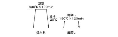
- the example of the hardening process and tempering process with respect to steel is shown in FIG.1 and FIG.3.
- a hardening process and a tempering process are performed to steel as a 1st process.
- low temperature and short-time carbonitriding is performed for 120 minutes at the A1 transformation point (723 ° C.) or more and 850 ° C. or less (800 ° C. in FIG. 1).
- carbonizing and nitriding may be performed.
- a hardening process and a tempering process are performed with respect to steel materials as a 2nd process following a 1st process.
- quenching is performed at the A1 transformation point (723 ° C.) or more and 850 ° C. or less (780 ° C. in FIG. 3), followed by tempering.
- the temperings of the first and second steps shown in FIGS. 1 and 3 are both at 150 ° C. for 120 minutes, and the quenching of the second step shown in FIG. 3 is 5 minutes.
- the temperature and time of quenching and tempering in the first step and the second step can be appropriately adjusted.
- the hardening and tempering process on the steel may be performed three or more times.
- surface nitrogen concentration (hereinafter referred to as “surface N concentration”) by adjusting the chemical composition of the steel, the conditions for nitrocarburizing, and the surface carbon concentration (hereinafter referred to as “surface C concentration”) when carburizing is also performed. 0.8% to 1.5% by mass, and the sum of surface N concentration and surface C concentration (hereinafter referred to as “surface (N + C) concentration”) is 1.5 to 2.5% by mass.
- the surface C concentration and the surface N concentration are the ratio of the mass to the base material in the portion where the carbon and nitrogen become the highest concentration in the vicinity of the surface of the steel (the depth from 200 m to the surface) .
- the surface (N + C) concentration refers to the ratio of the mass to the base material in the portion where nitrogen is the highest concentration and the portion where carbon is the highest concentration in the vicinity of the surface of the steel (the depth from 200m to the surface). It is the sum of the ratio of mass to base material.
- the steel which has C, Si, Mn, and Al performs the quenching and tempering process including the quenching process of A1 transformation point or more and 850 degrees C or less two or more times, and carries out the nitriding quenching processing which makes surface N concentration 0.8 mass% or more By performing processing so as to contain, the amount of retained austenite in the steel component is adjusted and the crystal grains are refined.
- the half value width of the steel component can be adjusted, and a steel component having an appropriate surface hardness can be easily manufactured.
- the surface hardness of steel parts decreases as the amount of retained austenite increases.
- the surface hardness after tempering at 300 ° C. becomes higher as the crystal size becomes finer. As a result, it is possible to obtain an appropriate surface hardness as a steel material used for gears of automobiles and the like.
- Hardening and tempering treatment is sequentially performed on a steel containing, by mass%, Si: 0.25 to 0.80%, Mn: 0.80 to 3.00%, Al: 0.05 to 1.20%
- the surface C concentration: 0.25 to 1.10% by mass and the surface N concentration: 0.8 to 1.5% by mass by performing the quenching and tempering step to be applied a plurality of times, and the amounts and sizes of MnSiN 2 and AlN And optimize the crystal grain size until the half width becomes 7.00 deg or more.
- each element is in the above range, and (surface N concentration (mass%)-Si (mass%)-0.52 x Al (mass%)) ⁇ 0.60 (%) It is required to meet In addition, it is considered effective to suppress the generation of voids by quenching treatment at a low temperature for a short time of 120 minutes at the A1 transformation point (723 ° C.) or more and 850 ° C. or less.
- the steel is subjected to at least one quenching and tempering step in which quenching treatment and tempering treatment of A1 transformation point to 850 ° C. are sequentially performed on the steel (first step), and after the quenching and tempering step A shot peening process is performed as a miniaturization process (second step).
- a hardening process and a tempering process are performed to steel as a 1st process.
- low temperature and short-time carbonitriding is performed for 120 minutes at the A1 transformation point (723 ° C.) or more and 850 ° C. or less (800 ° C. in FIG. 1).
- carbonizing and nitriding may be performed.
- a shot peening treatment with an arc height of 0.40 mmA or more is performed following the first step.
- the steel containing C, Si, Mn, and Al is subjected to at least one quenching and tempering step in which a quenching treatment and a tempering treatment are sequentially applied to the steel, and thereafter shot peening is performed to obtain Cr and Mo
- steel parts can be manufactured without using an element that is rare and has a large environmental impact.
- steels having C, Si, Mn, and Al are subjected to a hardening and tempering process including a hardening treatment including A1 transformation point to 850 ° C. or less, and then shot peening as grain refining treatment to obtain steel parts.
- the amount of retained austenite is adjusted to refine the crystal grains.
- the half value width of the steel component can be adjusted, and a steel component having an appropriate surface hardness can be easily manufactured.
- the hardening and tempering step was repeated twice in the first step and the second step.
- the quenching and tempering step hereinafter referred to as quenching and tempering A
- quenching and tempering C the quenching and tempering step
- quenching and tempering A the test piece is subjected to nitriding at 800 ° C. for 120 minutes, oil quenching at 65 ° C., and thereafter at 150 ° C. for 120 minutes in a vacuum furnace with controlled NH 3 concentration.
- a tempering process was performed.
- quenching and tempering C water quenching was performed at room temperature after being held at 780 ° C. for 5 minutes in an electric furnace in air atmosphere, and then tempering was performed at 150 ° C. for 120 minutes.
- quenching and tempering C was further performed after the second step (third step).
- the second step is carried out by performing hardening and tempering A (see FIG. 1) once as the first step. Shot peening was done.
- a quenching and tempering step (hereinafter, referred to as quenching and tempering B) shown in FIG. 2 was performed as a first step, and shot peening was performed as a second step.
- quenching and tempering B the test piece is subjected to carbonitriding treatment at 800 ° C. for 120 minutes, oil quenching treatment at 120 ° C., and then tempering at 150 ° C. for 120 minutes in a vacuum furnace with controlled NH 3 concentration. I did the processing.
- the NH 3 concentration in the quenching and tempering step in the first step of each of Inventive Examples 1 to 8 and Comparative Examples 9 to 14 was controlled (high concentration, medium concentration, low concentration) as shown in Table 2.
- the C concentration distribution and N concentration distribution from the surface of each test piece are measured by EPMA (Electron Probe Micro Analyzer), and the highest concentration in the vicinity of each surface (the depth from the surface to 200 ⁇ m) is the surface C concentration, surface N It was the concentration.
- EPMA Electro Probe Micro Analyzer
- each test piece was measured by an X-ray residual stress measuring apparatus ( ⁇ -X360 manufactured by Pulstec Industrial Co., Ltd.) to calculate the amount of retained austenite and the half width. Measurement conditions are: incident angle: 35 ° C., collimator diameter: ⁇ 1.0 mm, X-ray intensity: 30 kV / 1 mA, X-ray wavelength: K ⁇ 2.29093 ⁇ , K ⁇ 2.08480 ⁇ , measurement distance: 39 mm, diffraction surface: 211 surface, and did. These measurements are performed after the second step in the invention examples 1 to 4 and 6 to 8 and the comparative examples 9 and 13 to 14, after the third step in the invention example 5, and after the first step in the comparative examples 10 to 12. The These are shown in the evaluation 1 of Table 3 below.
- the test pieces of Inventive Examples 1 to 8 and Comparative Examples 9 to 14 were subjected to tempering at 300 ° C. for 240 minutes for evaluation as shown in FIG.
- the hardness distribution from the surface was measured with a micro Vickers hardness meter (load: 300 gf) before 300 ° C. tempering (time C in FIG. 4) and after 300 ° C. tempering (time D in FIG. 4).
- the hardness at a position of 50 ⁇ m from the surface was taken as the surface hardness before and after 300 ° C. tempering.
- the hardness of the position of 0.2 mm from the surface was confirmed from the hardness distribution measured after 300 degreeC tempering.
- the vicinity of the surface of the cross section of the test piece was observed with an optical microscope to confirm the presence or absence of generation of a void.
- the half hardness is 7 deg or more, and the surface hardness after tempering at 300 ° C. is HV 680 or more to prevent pitting fracture and the like. Tooth surface strength can be secured. Further, in the invention examples 1 to 8, since the hardness at the position of 0.2 mm from the surface after tempering at 300 ° C. is HV600 or more, the spalling can be suppressed. Furthermore, in the invention examples 1 to 3, since the surface hardness before tempering at 300 ° C. is less than HV 660, the tooth contact is improved, and the generation of noise and the contact can be suppressed. Further, in the invention examples 5 to 8, since the half width is 7.65 or more and the hardness after tempering at 300 ° C. is HV 700 or more, the tooth surface strength can be improved.
- Inventive Examples 1 to 8 a void-free structure was obtained under an environment where the surface N concentration is 0.8% by mass or more.
- the material having small environmental load and easy to obtain is used, and the surface N concentration is immersed at 0.8 mass% or more at the A1 transformation point (723 ° C.) or more and 850 ° C. or less.
- a steel part such as a gear having an appropriate hardness can be obtained by performing a quenching and tempering process including a nitriding and quenching process at least once and performing a grain refining process after the quenching and tempering process.
- the grain refining process is a further quenching and tempering process or shot peening with an arc height of 0.40 mmA or more.
- the test pieces of the invention examples 1 to 8 have a surface N concentration of 0.8 mass% or more, and (surface N concentration (mass%)-Si (mass%)-0.52 x Al (mass%)) Contains a surface layer of 0.20 to 0.55%.
- the surface hardness after tempering at 300 ° C. is as low as HV 650 or less because the crystal grains are coarse (the half width is small at less than 7 deg).
- the surface N concentration is low, the amount of Si, Mn, and Al is small, and the crystal grain is coarse (half width less than 7 deg is small), so the surface hardness after tempering at 300 ° C. is HV 650 or less and low. The occurrence of voids was observed.
- the present invention can be widely used for automobile parts and machine parts.
Landscapes
- Chemical & Material Sciences (AREA)
- Engineering & Computer Science (AREA)
- Mechanical Engineering (AREA)
- Materials Engineering (AREA)
- Metallurgy (AREA)
- Organic Chemistry (AREA)
- Crystallography & Structural Chemistry (AREA)
- Physics & Mathematics (AREA)
- Thermal Sciences (AREA)
- Heat Treatment Of Articles (AREA)
Abstract
適正な表面硬さを有する鋼部品を容易に製造できる鋼部品の製造方法を提供する。質量%で、C:0.25~1.10%、Si:0.25~0.80%、Mn:0.80~3.00%、Al:0.05~1.20%を有する鋼を用い、当該鋼に対してA1変態点以上850℃以下の焼入れ処理及び焼戻し処理が順に施される焼入れ焼戻し工程を少なくとも1回行い、焼入れ処理は、表面窒素濃度を0.8%以上とする浸窒焼入れ処理を含み、焼入れ焼戻し工程の後に結晶粒微細化処理を行う。
Description
本発明は、鋼部品の製造方法および鋼部品に関する。
自動車のトランスミッション等で使用される歯車や軸受等の鋼部品は、クロム鋼やクロムモリブデン鋼を用いて部品加工を行い、浸炭焼入れ焼戻しを行って製造していた。近年、CO2排出量の削減を通じた地球温暖化防止や省資源化の要請が高まっており、更なる燃費向上のために車両の軽量化が求められている。このために、鋼部品は、小型化が要求されて負荷が増大することから、更なる高強度化が求められている。また、自動車に用いられる鋼部品は、環境温度が約300℃にまで達することから、鋼部品の表面の硬さが低下し、ピッチング破壊が起こることがある。このため、耐ピッチング疲労特性の向上のためには、焼き戻し軟化抵抗に優れた鋼部品が求められる。
特許文献1に記載の技術では、質量%で、Siを0.7~1.0%、Crを1.0~1.5%含有した鋼に浸炭焼入れ焼戻しを施した鋼部品において、表面から50μm深さの部分のC含有量(以下、「表面C濃度」と称する。)を0.9~1.1%にし、残留オーステナイト量を30%未満にして、300℃に焼戻した(以下、「300℃焼戻し」と称する。)後の鋼部品の表面から50μm深さの部分の硬さ(以下、「表面硬さ」と称する。)がビッカース硬さ(以下、「HV」と称する。)700以上になるようにしている。
特許文献2に記載の技術では、Si+0.2Cr+0.01Moを1.3%超含有する鋼材とすることで、300℃焼戻し後の鋼部品の表面硬さがHV700以上になるようにしている。
特許文献3に記載の技術では、Si、Mn、Cr、Mo等を適量含有する鋼を部品形状に成形し、浸炭焼入れ、焼戻しまたは浸炭浸窒焼入れ、焼戻し後の硬さをHRC58(HV653相当)以上とし、(焼入れ焼戻し後の表面硬さ)―(300℃焼戻し後の表面硬さ)がHV130以下になるように鋼部品が構成されている。
特許文献4に記載の技術では、従来の浸炭窒化では鋼の表面の窒素濃度が0.8%を超えるとボイドが発生する課題に対し、フェライト領域で窒化後再加熱焼入れすることが提案されている。この処理によって、0.8%を超える窒素を固溶させるこができるため、高い窒素濃度を実現することができ、その際の窒素濃度の上限が示されている。また、特許文献5に記載の技術では、特許文献4と同様の課題に対し、軟窒化処理と高周波焼入れとを組み合わせることが示されている。
例えば鋼部品を自動車の歯車として使用する場合、鋼製歯車において、ピッチング破壊等を防止するための歯面強度を確保する上で、300℃焼戻し後の表面硬さがHV680以上であることが好ましい。
特許文献1~3では、鋼部品の製造に際し、母材に対して浸炭焼入れが950℃前後で行われる。また、母材に対して焼入れが2回行われる場合であっても、2回目の焼入れ温度は850℃以上に設定されている。母材に対して850℃以上で焼入れを行うと、オーステナイト粒が粗大化するため、焼入れ後の鋼部品は結晶粒が粗くなる。そうなると、鋼部品を歯車として用いる場合に歯面強度が不足するおそれがある。
特許文献4及び5の鋼部品では、窒化処理の処理温度が500~600℃であって、A1変態点(723℃)以下での処理であるため、母材に対するNの侵入・拡散が遅く、処理に長時間を要する。また、窒化処理後の再加熱時において窒化物を固溶させるべく表面N濃度を低く制御することが必要なことから、さらに処理が長時間化する。加えて、再加熱時の温度を900℃以上にすることで、脱炭素、脱窒素や、結晶粒の粗大化を招くことになり、鋼部品の耐久性が低下する。また、特許文献1~5では、いずれの鋼部品も、母材にCr、Mo、Ni、V等の希少元素を含有しており、これらは再利用が容易ではないため環境負荷も大きい。
上記実情に鑑み、適正な表面硬さを有する鋼部品を容易に製造できる鋼部品の製造方法が望まれている。
本発明の鋼部品の製造方法の特徴構成は、質量%で、C:0.25~1.10%、Si:0.25~0.80%、Mn:0.80~3.00%、Al:0.05~1.20%を有する鋼を用い、当該鋼に対してA1変態点以上850℃以下の焼入れ処理及び焼戻し処理が順に施される焼入れ焼戻し工程を少なくとも1回行い、前記焼入れ処理は、表面窒素濃度を0.8質量%以上とする浸窒焼入れ処理を含み、前記焼入れ焼戻し工程の後に結晶粒微細化処理を行う点にある。
本構成のように、C、Si、Mn、Alを有する鋼を用い、当該鋼に対して焼入れ及び焼戻しが順に施される焼入れ焼戻し工程と、結晶粒微細化処理とを行うことで、Cr、Moのように希少であって環境負荷が大きい元素を用いることなく、鋼部品を製造することができる。また、C、Si、Mn、Alを有する鋼は、A1変態点以上850℃以下を含む焼入れ焼戻し工程を、表面窒素濃度を0.8質量%以上とする浸窒焼入れ処理を含む形態で行った後に、結晶粒微細化処理を行うことで、鋼部品の結晶粒サイズが調整され、適正な表面硬さを有する鋼部品を簡便に製造することができる。
他の特徴構成は、前記結晶粒微細化処理として、アークハイトが0.40mmA以上のショットピーニングを行う点にある。
本構成のように、結晶粒微細化処理として、アークハイトが0.40mmA以上のショットピーニングを行うことで、鋼部品の結晶粒を微細にすることができ、適正な表面硬さを有する鋼部品を簡便に製造することができる。
他の特徴構成は、前記結晶粒微細化処理として、前記焼入れ焼戻し工程を行う点にある。
本構成のように、結晶粒微細化処理として、A1変態点以上850℃以下の焼入れ処理及び焼戻し処理が順に施される焼入れ焼戻し工程を行うことで、鋼部品の結晶粒を微細にすることができ、適正な表面硬さを有する鋼部品を簡便に製造することができる。
本発明の鋼部品の特徴構成は、質量%で、C:0.25~1.10%、Si:0.25~0.80%、Mn:0.80~3.00%、Al:0.05~1.20%を有する母材と、前記母材の表面における表面窒素濃度が0.8質量%以上であり、且つ、(表面窒素濃度(質量%)-Si(質量%)-0.52×Al(質量%))が0.20~0.55%である表面層と、を含み、半価幅を7deg以上とした点にある。
上記構成によれば、自動車部品等に用いられる歯車等の鋼部品において適正な表面硬さを得ることができる。
以下に、本発明に係る鋼部品の製造方法を説明する。鋼部品は、例えば歯車、減速機、軸受等に用いられる。
〔第1実施形態〕
鋼部品の母材には、化学成分として、質量%で、C:0.25~1.10%、Si:0.25~0.80%、Mn:0.80~3.00%、Al:0.05~1.20%を有する鋼を用いる。当該鋼に対して焼入れ処理及び焼戻し処理が順に施される焼入れ焼戻し工程を複数回行うことで、鋼部品を製造する。
鋼部品の母材には、化学成分として、質量%で、C:0.25~1.10%、Si:0.25~0.80%、Mn:0.80~3.00%、Al:0.05~1.20%を有する鋼を用いる。当該鋼に対して焼入れ処理及び焼戻し処理が順に施される焼入れ焼戻し工程を複数回行うことで、鋼部品を製造する。
本実施形態では、鋼に対してA1変態点以上850℃以下の焼入れ処理及び焼戻し処理が順に施される焼入れ焼戻し工程を少なくとも1回行い(第1工程)、当該焼入れ焼戻し工程の後に、結晶粒微細化処理として、更に焼入れ焼戻し工程を行う(第2工程)。図1及び図3に、鋼に対する焼入れ処理及び焼戻し処理の例を示す。鋼に対し、第1工程として、焼入れ処理及び焼戻し処理を行う。焼入れ処理については、A1変態点(723℃)以上850℃以下(図1では800℃)で120分間の低温短時間の浸窒焼入れを行う。浸窒焼入れに代えて、浸炭浸窒焼入れを行ってもよい。第1工程に続いて第2工程として、鋼材に対し、焼入れ処理及び焼戻し処理を行う。第2工程では、A1変態点(723℃)以上850℃以下(図3では780℃)の焼入れを行い、続いて焼戻しを行う。
図1及び図3に示される第1工程及び第2工程の焼き戻しは、共に150℃で120分間であり、図3に示される第2工程の焼入れは5分間である。第1工程及び第2工程の焼入れ及び焼戻しの温度及び時間は適宜調整することができる。鋼に対する焼入れ焼戻し工程は3回以上行ってもよい。
鋼の化学成分、浸窒焼入れ条件、及び、浸炭も行う場合には表面炭素濃度(以下、「表面C濃度」と称する。)等を調整し、表面窒素濃度(以下、「表面N濃度」と称する。)を0.8~1.5質量%、表面N濃度と表面C濃度との和(以下、「表面(N+C)濃度」と称する。)を1.5~2.5質量%とした。ここで、表面C濃度、表面N濃度とは、鋼の表面近傍(表面から200μmまでの深さ部分)において、炭素及び窒素がそれぞれ最高濃度となる部分における母材に対する質量の比率のことである。また、表面(N+C)濃度とは、鋼の表面近傍(表面から200μmまでの深さ部分)において、窒素が最高濃度となる部分における母材に対する質量の比率と、炭素が最高濃度となる部分における母材に対する質量の比率との和のことである。
C、Si、Mn、Alを有する鋼を用い、当該鋼に対して焼入れ処理及び焼戻し処理が順に施される焼入れ焼戻し工程を複数回行うことで、Cr、Moのように希少であって環境負荷が大きい元素を用いることなく、鋼部品を製造することができる。また、C、Si、Mn、Alを有する鋼は、A1変態点以上850℃以下の焼入れ処理を含む焼入れ焼戻し工程を複数回行い、表面N濃度を0.8質量%以上とする浸窒焼入れ処理を含むように処理を行うことで、鋼部品において残留オーステナイト量が調整されて結晶粒が微細化される。その結果、鋼部品の半価幅を調整することができ、適正な表面硬さを有する鋼部品を簡便に製造することができる。なお、鋼部品は、残留オーステナイト量が増加するにつれて表面硬さは低くなる。また、結晶サイズが微細になるにつれて300℃焼戻し後の表面硬さは高くなる。その結果、自動車等の歯車に用いられる鋼材として適正な表面硬さを得ることができる。
質量%で、Si:0.25~0.80%、Mn:0.80~3.00%、Al:0.05~1.20%を含有する鋼に対して焼入れ処理及び焼戻し処理が順に施される焼入れ焼戻し工程を複数回行って、表面C濃度:0.25~1.10質量%、表面N濃度:0.8~1.5質量%となり、MnSiN2、及び、AlNの量とサイズとを最適化して、半価幅が7.00deg以上となるまで結晶粒を微細化する。
表面C濃度、表面N濃度、Mn、Siの含有量を高めて結晶粒を微細化すると、原子間相互作用によりC、Nの拡散、転位の移動が抑制されるため、鋼の軟化抵抗が高まるものと考えられる。また、表面N濃度を高めて結晶粒を微細化することで、300℃焼戻し時にFe4Nが多量かつ均一微細に析出するようになるため、鋼部品の軟化抵抗が高まるものと考えられる。
鋼のSi、Mn、Alの含有量を高くしつつ浸窒焼入れ後の表面N濃度を高めることで、Nの拡散を抑制しつつMnSiN2、AlNを多量に析出させて、N、Hのガス化によるボイドの発生を防止した。このためには、各元素が上記の範囲内であって、かつ、(表面N濃度(質量%)- Si(質量%) -0.52×Al(質量%)) <0.60(%)を満たすことが必要とされる。また、A1変態点(723℃)以上850℃以下で120分間の低温短時間の焼入れ処理もボイドの発生を抑制するために有効と考えられる。
〔第2実施形態〕
本実施形態では、鋼に対してA1変態点以上850℃以下の焼入れ処理及び焼戻し処理が順に施される焼入れ焼戻し工程を少なくとも1回行い(第1工程)、当該焼入れ焼戻し工程の後に、結晶粒微細化処理として、ショットピーニング処理を行う(第2工程)。鋼に対し、第1工程として、焼入れ処理及び焼戻し処理を行う。焼入れ処理については、A1変態点(723℃)以上850℃以下(図1では800℃)で120分間の低温短時間の浸窒焼入れを行う。浸窒焼入れに代えて、浸炭浸窒焼入れを行ってもよい。第1工程に続いて第2工程として、アークハイトが0.40mmA以上のショットピーニング処理を行う。
本実施形態では、鋼に対してA1変態点以上850℃以下の焼入れ処理及び焼戻し処理が順に施される焼入れ焼戻し工程を少なくとも1回行い(第1工程)、当該焼入れ焼戻し工程の後に、結晶粒微細化処理として、ショットピーニング処理を行う(第2工程)。鋼に対し、第1工程として、焼入れ処理及び焼戻し処理を行う。焼入れ処理については、A1変態点(723℃)以上850℃以下(図1では800℃)で120分間の低温短時間の浸窒焼入れを行う。浸窒焼入れに代えて、浸炭浸窒焼入れを行ってもよい。第1工程に続いて第2工程として、アークハイトが0.40mmA以上のショットピーニング処理を行う。
C、Si、Mn、Alを有する鋼を用い、当該鋼に対して焼入れ処理及び焼戻し処理が順に施される焼入れ焼戻し工程を少なくとも1回行い、その後にショットピーニングを行うことで、Cr、Moのように希少であって環境負荷が大きい元素を用いることなく、鋼部品を製造することができる。また、C、Si、Mn、Alを有する鋼は、A1変態点以上850℃以下の焼入れ処理を含む焼入れ焼戻し工程を行った後に、結晶粒微細化処理としてショットピーニングを行うことで、鋼部品において残留オーステナイト量が調整されて結晶粒が微細化される。その結果、鋼部品の半価幅を調整することができ、適正な表面硬さを有する鋼部品を簡便に製造することができる。
以下に、本発明を実施例によって具体的に説明する。なお、これらの実施例は本発明を説明するためのものであって、本発明の範囲を限定するものではない。
以下の表1に示す化学成分を有する鋼塊を均熱処理後、圧延と焼準を施してからφ8×12mmの丸棒の試験片を加工した。図1、図3、及び、以下の表2に示すように、発明例1~5、及び、比較例9では、第1工程及び第2工程において、焼入れ焼戻し工程を2回繰り返した。第1工程では、図1に示す焼入れ焼戻し工程(以下、焼入れ焼戻しAと称する)を行い、続いて第2工程では、図3に示す焼入れ焼戻し工程(以下、焼入れ焼戻しCと称する)を行った。焼入れ焼戻しAでは、NH3濃度を制御した真空炉内において、試験片に対して800℃×120分間の浸窒処理を施し、65℃の油焼入れ処理を行い、その後に、150℃×120分間の焼戻し処理を行った。焼入れ焼戻しCでは、大気雰囲気の電気炉で780℃×5分間保持後に室温で水焼入れ処理を行い、その後に、150℃×120分間の焼戻し処理を行った。なお、発明5については、第2工程の後に、更に焼入れ焼戻しCを行った(第3工程)。
図1及び以下の表2に示すように、比較例10~12では、第1工程として、焼入れ焼戻しA(焼入れ焼戻し工程を1回)のみを行った。
図1、図2、及び以下の表2に示すように、発明例6~8、及び、比較例13では、第1工程として、焼入れ焼戻しA(図1参照)を1回行い、第2工程としてショットピーニングを行った。比較例14では、第1工程として、図2に示す焼入れ焼戻し工程(以下、焼入れ焼戻しBと称する)を行い、第2工程としてショットピーニングを行った。焼入れ焼戻しBでは、NH3濃度を制御した真空炉内において、試験片に対して800℃×120分間の浸窒処理を施し、120℃の油焼入れ処理を行い、その後に150℃×120分間の焼戻し処理を行った。なお、発明例1~8及び比較例9~14の第1工程の焼入れ焼戻し工程におけるNH3濃度は、表2に表示されるように制御(高濃度、中濃度、低濃度)した。


各試験片の表面からのC濃度分布、N濃度分布をEPMA(Electron Probe Micro Analyzer)で測定し、それぞれの表面近傍(表面から200μmまでの深さ部分)の最高濃度を表面C濃度、表面N濃度とした。これらの測定は、発明例1~8及び比較例9~13では第1工程後に行い、比較例14のみ第2工程後に行った。これらを以下の表3の評価1に示す。
各試験片の最表面をX線残留応力測定装置(パルステック工業(株)社製μ-X360)によって測定し、残留オーステナイト量、半価幅を算出した。測定条件は、入射角:35℃、コリメータ径:φ1.0mm、X線強度:30kV/1mA、X線波長:Kα2.29093Å、Kβ 2.08480Å、計測距離:39mm、回折面:211面、とした。これらの測定は、発明例1~4、6~8及び比較例9、13~14では第2工程後に行い、発明例5では第3工程後に行い、比較例10~12では第1工程後に行った。これらを以下の表3の評価1に示す。
発明例1~8及び、比較例9~14の試験片に対し、図4に示すように、評価用として300℃×240分間の焼戻しを施した。300℃焼戻し前(図4のCの時点)と、300℃焼戻し後(図4のDの時点)とにおいて、表面からの硬さ分布をマイクロビッカース硬度計(荷重300gf)で測定した。測定されたそれぞれの硬さ分布において、表面から50μmの位置の硬さを300℃焼戻し前後の表面硬さとした。また、300℃焼戻し後に測定された硬さ分布から表面から0.2mmの位置の硬さを確認した。さらに、試験片断面の表面近傍を光学顕微鏡で観察し、ボイドの発生の有無を確認した。これらを以下の表3の評価2及び評価3に示す。

例えば、鋼部品が自動車の歯車である場合、発明例1~8では、半価値が7deg以上であり300℃焼戻し後の表面硬さはHV680以上であることで、ピッチング破壊等を防止するための歯面強度を確保することができる。また、発明例1~8では、300℃焼き戻し後の表面から0.2mm位置の硬さがHV600以上であるので、スポーリングの抑制が可能になる。さらに、発明例1~3では、300℃焼戻し前の表面硬さがHV660未満であるため、歯当たりが改善され、ノイズの発生や片当たりを抑制することができる。また、発明例5~8では、半価幅が7.65以上であり、300℃焼戻し後の硬さがHV700以上であるため、歯面強度を向上させることができる。
さらに、発明例1~8では、表面N濃度が0.8質量%以上の環境下においてボイドの無い組織が得られた。このように、発明例1~8によれば、環境負荷が小さく入手が容易な材料を用い、A1変態点(723℃)以上850℃以下において、表面N濃度を0.8質量%以上の浸窒焼入れ工程を含む焼入れ焼戻し工程を少なくとも1回行い、焼入れ焼戻し工程の後に、結晶粒微細化処理を行うことで、適正な硬度を有する歯車等の鋼部品を得ることができる。ここで、結晶粒微細化処理とは、更なる焼入れ焼戻し工程、又は、アークハイトが0.40mmA以上のショットピーニングである。発明例1~8の試験片は、表面N濃度が0.8質量%以上であり、且つ、(表面N濃度(質量%)-Si(質量%)-0.52×Al(質量%))が0.20~0.55%である表面層を含む。
比較例9では、表面N濃度が0.8質量%よりも低く、Si、Mn、Alが少ないことから、300℃焼戻し後の表面硬さがHV660以下と低く、ボイドの発生が認められた。
比較例10では、結晶粒が粗い(半価幅が7deg未満で小さい)ため、300℃焼戻し後の表面硬さがHV650以下であって低い。比較例11では、表面N濃度が低く、Si、Mn、Alが少なく、結晶粒が粗い(半価幅が7deg未満で小さい)ため、300℃焼戻し後の表面硬さがHV650以下であって低く、ボイドの発生が認められた。比較例12では、(表面N濃度(質量%)-Si(質量%)-0.52×Al(質量%))が0.60(%)であって高いことから、ボイドの発生が認められた。また、比較例10~12では、焼入れ焼戻し工程が1回であることから、表面の残留オーステナイト量が62質量%、52質量%。71質量%と高くなり、300℃焼戻し後の表面硬さの低下(HV665以下)を招いている。
比較例13,14では、第2工程のショットピーニングにおけるアークハイト値が小さいため、半価幅は7deg未満で小さく300℃焼戻し後の表面硬さが低い。
本発明は、自動車用部品や機械部品に広く利用することができる。
Claims (4)
- 質量%で、C:0.25~1.10%、Si:0.25~0.80%、Mn:0.80~3.00%、Al:0.05~1.20%を有する鋼を用い、当該鋼に対してA1変態点以上850℃以下の焼入れ処理及び焼戻し処理が順に施される焼入れ焼戻し工程を少なくとも1回行い、前記焼入れ処理は、表面窒素濃度を0.8質量%以上とする浸窒焼入れ処理を含み、前記焼入れ焼戻し工程の後に結晶粒微細化処理を行う、鋼部品の製造方法。
- 前記結晶粒微細化処理として、アークハイトが0.40mmA以上のショットピーニングを行う、請求項1に記載の鋼部品の製造方法。
- 前記結晶粒微細化処理として、前記焼入れ焼戻し工程を行う、請求項1に記載の鋼部品の製造方法。
- 質量%で、C:0.25~1.10%、Si:0.25~0.80%、Mn:0.80~3.00%、Al:0.05~1.20%を有する母材と、前記母材の表面における表面窒素濃度が0.8質量%以上であり、且つ、(表面窒素濃度(質量%)-Si(質量%)-0.52×Al(質量%))が0.20~0.55%である表面層と、を含み、半価幅を7deg以上とした鋼部品。
Priority Applications (1)
| Application Number | Priority Date | Filing Date | Title |
|---|---|---|---|
| JP2019534533A JPWO2019026909A1 (ja) | 2017-08-03 | 2018-07-31 | 鋼部品の製造方法および鋼部品 |
Applications Claiming Priority (2)
| Application Number | Priority Date | Filing Date | Title |
|---|---|---|---|
| JP2017150791 | 2017-08-03 | ||
| JP2017-150791 | 2017-08-03 |
Publications (1)
| Publication Number | Publication Date |
|---|---|
| WO2019026909A1 true WO2019026909A1 (ja) | 2019-02-07 |
Family
ID=65232653
Family Applications (1)
| Application Number | Title | Priority Date | Filing Date |
|---|---|---|---|
| PCT/JP2018/028676 Ceased WO2019026909A1 (ja) | 2017-08-03 | 2018-07-31 | 鋼部品の製造方法および鋼部品 |
Country Status (2)
| Country | Link |
|---|---|
| JP (1) | JPWO2019026909A1 (ja) |
| WO (1) | WO2019026909A1 (ja) |
Citations (9)
| Publication number | Priority date | Publication date | Assignee | Title |
|---|---|---|---|---|
| JPH10176219A (ja) * | 1996-12-17 | 1998-06-30 | Komatsu Ltd | 高耐面圧用鋼部品およびその製造方法 |
| JP2003226918A (ja) * | 2001-11-29 | 2003-08-15 | Ntn Corp | 軸受部品、その熱処理方法および転がり軸受 |
| JP2004285474A (ja) * | 2003-03-04 | 2004-10-14 | Komatsu Ltd | 転動部材およびその製造方法 |
| JP2007224353A (ja) * | 2006-02-22 | 2007-09-06 | Nsk Ltd | ラックアンドピニオン式電動パワーステアリング装置 |
| WO2009054530A1 (ja) * | 2007-10-24 | 2009-04-30 | Nippon Steel Corporation | 高温での面圧疲労強度に優れた浸炭窒化高周波焼入れ鋼部品及びその製造方法 |
| JP2010255099A (ja) * | 2009-03-31 | 2010-11-11 | Jfe Steel Corp | 異物環境下での転動疲労特性に優れた軸受部品の製造方法 |
| WO2011114836A1 (ja) * | 2010-03-19 | 2011-09-22 | 新日本製鐵株式会社 | 表層硬化処理用鋼及び表層硬化鋼部品とその製造方法 |
| JP2014012870A (ja) * | 2012-07-04 | 2014-01-23 | Daido Steel Co Ltd | 水素脆性型の面疲労強度に優れた浸炭窒化部品 |
| US20170044636A1 (en) * | 2015-08-12 | 2017-02-16 | Kia Motors Corporation | Carburized steel and method of manufacturing the same |
-
2018
- 2018-07-31 JP JP2019534533A patent/JPWO2019026909A1/ja active Pending
- 2018-07-31 WO PCT/JP2018/028676 patent/WO2019026909A1/ja not_active Ceased
Patent Citations (9)
| Publication number | Priority date | Publication date | Assignee | Title |
|---|---|---|---|---|
| JPH10176219A (ja) * | 1996-12-17 | 1998-06-30 | Komatsu Ltd | 高耐面圧用鋼部品およびその製造方法 |
| JP2003226918A (ja) * | 2001-11-29 | 2003-08-15 | Ntn Corp | 軸受部品、その熱処理方法および転がり軸受 |
| JP2004285474A (ja) * | 2003-03-04 | 2004-10-14 | Komatsu Ltd | 転動部材およびその製造方法 |
| JP2007224353A (ja) * | 2006-02-22 | 2007-09-06 | Nsk Ltd | ラックアンドピニオン式電動パワーステアリング装置 |
| WO2009054530A1 (ja) * | 2007-10-24 | 2009-04-30 | Nippon Steel Corporation | 高温での面圧疲労強度に優れた浸炭窒化高周波焼入れ鋼部品及びその製造方法 |
| JP2010255099A (ja) * | 2009-03-31 | 2010-11-11 | Jfe Steel Corp | 異物環境下での転動疲労特性に優れた軸受部品の製造方法 |
| WO2011114836A1 (ja) * | 2010-03-19 | 2011-09-22 | 新日本製鐵株式会社 | 表層硬化処理用鋼及び表層硬化鋼部品とその製造方法 |
| JP2014012870A (ja) * | 2012-07-04 | 2014-01-23 | Daido Steel Co Ltd | 水素脆性型の面疲労強度に優れた浸炭窒化部品 |
| US20170044636A1 (en) * | 2015-08-12 | 2017-02-16 | Kia Motors Corporation | Carburized steel and method of manufacturing the same |
Also Published As
| Publication number | Publication date |
|---|---|
| JPWO2019026909A1 (ja) | 2020-06-25 |
Similar Documents
| Publication | Publication Date | Title |
|---|---|---|
| CN105026602B (zh) | 高频淬火构件的半成品及其制造方法 | |
| KR100961584B1 (ko) | 침탄 고주파 담금질 부품 | |
| JP5530763B2 (ja) | 低サイクル曲げ疲労強度に優れた浸炭鋼部品 | |
| JP5099276B1 (ja) | 面疲労強度に優れたガス浸炭鋼部品、ガス浸炭用鋼材およびガス浸炭鋼部品の製造方法 | |
| KR101294900B1 (ko) | 연질화용 강 및 연질화 강 부품 및 그 제조 방법 | |
| WO2010137607A1 (ja) | 浸炭部品およびその製造方法 | |
| WO2011111269A1 (ja) | 低サイクル曲げ疲労強度に優れた浸炭鋼部品 | |
| WO2014192117A1 (ja) | 軟窒化高周波焼入れ鋼部品 | |
| JP7152832B2 (ja) | 機械部品 | |
| KR20130004307A (ko) | 템퍼링 연화 저항성이 우수한 강 부품 | |
| CN1539026A (zh) | 渗碳淬火部件及其制造方法 | |
| JP2008261037A (ja) | ショットピーニングを施した鋼製の浸炭部品又は浸炭窒化部品 | |
| JP6601358B2 (ja) | 浸炭部品およびその製造方法 | |
| JP2021113338A (ja) | 鋼部品及びその製造方法 | |
| WO2017170540A1 (ja) | 面疲労強度および曲げ疲労強度に優れた浸炭窒化部品、並びにその製造方法 | |
| KR101860658B1 (ko) | 진공 침탄용 강재 및 그의 제조 방법 | |
| JP2020041186A (ja) | ガス浸炭用肌焼鋼及びガス浸炭部品 | |
| JP7013833B2 (ja) | 浸炭部品 | |
| JP6160054B2 (ja) | 耐高面圧部品 | |
| JP5821512B2 (ja) | 窒化部品およびその製造方法 | |
| JP2023102175A (ja) | 鋼部材 | |
| CN109415789B (zh) | Cvt滑轮用钢材、cvt滑轮以及cvt滑轮的制造方法 | |
| JPWO2019026909A1 (ja) | 鋼部品の製造方法および鋼部品 | |
| JP2020033638A (ja) | 部品およびその製造方法 | |
| JP7862701B2 (ja) | 鋼、および、浸炭焼入れ部品 |
Legal Events
| Date | Code | Title | Description |
|---|---|---|---|
| 121 | Ep: the epo has been informed by wipo that ep was designated in this application |
Ref document number: 18840772 Country of ref document: EP Kind code of ref document: A1 |
|
| ENP | Entry into the national phase |
Ref document number: 2019534533 Country of ref document: JP Kind code of ref document: A |
|
| NENP | Non-entry into the national phase |
Ref country code: DE |
|
| 122 | Ep: pct application non-entry in european phase |
Ref document number: 18840772 Country of ref document: EP Kind code of ref document: A1 |