WO2019026892A1 - Hydraulic drive device - Google Patents
Hydraulic drive device Download PDFInfo
- Publication number
- WO2019026892A1 WO2019026892A1 PCT/JP2018/028612 JP2018028612W WO2019026892A1 WO 2019026892 A1 WO2019026892 A1 WO 2019026892A1 JP 2018028612 W JP2018028612 W JP 2018028612W WO 2019026892 A1 WO2019026892 A1 WO 2019026892A1
- Authority
- WO
- WIPO (PCT)
- Prior art keywords
- pump
- electric motor
- hydraulic
- supply
- command value
- Prior art date
Links
Images

Classifications
-
- F—MECHANICAL ENGINEERING; LIGHTING; HEATING; WEAPONS; BLASTING
- F04—POSITIVE - DISPLACEMENT MACHINES FOR LIQUIDS; PUMPS FOR LIQUIDS OR ELASTIC FLUIDS
- F04B—POSITIVE-DISPLACEMENT MACHINES FOR LIQUIDS; PUMPS
- F04B1/00—Multi-cylinder machines or pumps characterised by number or arrangement of cylinders
- F04B1/12—Multi-cylinder machines or pumps characterised by number or arrangement of cylinders having cylinder axes coaxial with, or parallel or inclined to, main shaft axis
- F04B1/26—Control
- F04B1/30—Control of machines or pumps with rotary cylinder blocks
- F04B1/32—Control of machines or pumps with rotary cylinder blocks by varying the relative positions of a swash plate and a cylinder block
- F04B1/324—Control of machines or pumps with rotary cylinder blocks by varying the relative positions of a swash plate and a cylinder block by changing the inclination of the swash plate
-
- F—MECHANICAL ENGINEERING; LIGHTING; HEATING; WEAPONS; BLASTING
- F15—FLUID-PRESSURE ACTUATORS; HYDRAULICS OR PNEUMATICS IN GENERAL
- F15B—SYSTEMS ACTING BY MEANS OF FLUIDS IN GENERAL; FLUID-PRESSURE ACTUATORS, e.g. SERVOMOTORS; DETAILS OF FLUID-PRESSURE SYSTEMS, NOT OTHERWISE PROVIDED FOR
- F15B15/00—Fluid-actuated devices for displacing a member from one position to another; Gearing associated therewith
- F15B15/18—Combined units comprising both motor and pump
-
- F—MECHANICAL ENGINEERING; LIGHTING; HEATING; WEAPONS; BLASTING
- F04—POSITIVE - DISPLACEMENT MACHINES FOR LIQUIDS; PUMPS FOR LIQUIDS OR ELASTIC FLUIDS
- F04B—POSITIVE-DISPLACEMENT MACHINES FOR LIQUIDS; PUMPS
- F04B1/00—Multi-cylinder machines or pumps characterised by number or arrangement of cylinders
- F04B1/12—Multi-cylinder machines or pumps characterised by number or arrangement of cylinders having cylinder axes coaxial with, or parallel or inclined to, main shaft axis
- F04B1/20—Multi-cylinder machines or pumps characterised by number or arrangement of cylinders having cylinder axes coaxial with, or parallel or inclined to, main shaft axis having rotary cylinder block
- F04B1/22—Multi-cylinder machines or pumps characterised by number or arrangement of cylinders having cylinder axes coaxial with, or parallel or inclined to, main shaft axis having rotary cylinder block having two or more sets of cylinders or pistons
-
- F—MECHANICAL ENGINEERING; LIGHTING; HEATING; WEAPONS; BLASTING
- F04—POSITIVE - DISPLACEMENT MACHINES FOR LIQUIDS; PUMPS FOR LIQUIDS OR ELASTIC FLUIDS
- F04B—POSITIVE-DISPLACEMENT MACHINES FOR LIQUIDS; PUMPS
- F04B17/00—Pumps characterised by combination with, or adaptation to, specific driving engines or motors
- F04B17/03—Pumps characterised by combination with, or adaptation to, specific driving engines or motors driven by electric motors
-
- F—MECHANICAL ENGINEERING; LIGHTING; HEATING; WEAPONS; BLASTING
- F04—POSITIVE - DISPLACEMENT MACHINES FOR LIQUIDS; PUMPS FOR LIQUIDS OR ELASTIC FLUIDS
- F04B—POSITIVE-DISPLACEMENT MACHINES FOR LIQUIDS; PUMPS
- F04B49/00—Control, e.g. of pump delivery, or pump pressure of, or safety measures for, machines, pumps, or pumping installations, not otherwise provided for, or of interest apart from, groups F04B1/00 - F04B47/00
- F04B49/002—Hydraulic systems to change the pump delivery
-
- F—MECHANICAL ENGINEERING; LIGHTING; HEATING; WEAPONS; BLASTING
- F04—POSITIVE - DISPLACEMENT MACHINES FOR LIQUIDS; PUMPS FOR LIQUIDS OR ELASTIC FLUIDS
- F04B—POSITIVE-DISPLACEMENT MACHINES FOR LIQUIDS; PUMPS
- F04B49/00—Control, e.g. of pump delivery, or pump pressure of, or safety measures for, machines, pumps, or pumping installations, not otherwise provided for, or of interest apart from, groups F04B1/00 - F04B47/00
- F04B49/06—Control using electricity
- F04B49/065—Control using electricity and making use of computers
-
- F—MECHANICAL ENGINEERING; LIGHTING; HEATING; WEAPONS; BLASTING
- F04—POSITIVE - DISPLACEMENT MACHINES FOR LIQUIDS; PUMPS FOR LIQUIDS OR ELASTIC FLUIDS
- F04B—POSITIVE-DISPLACEMENT MACHINES FOR LIQUIDS; PUMPS
- F04B49/00—Control, e.g. of pump delivery, or pump pressure of, or safety measures for, machines, pumps, or pumping installations, not otherwise provided for, or of interest apart from, groups F04B1/00 - F04B47/00
- F04B49/08—Regulating by delivery pressure
-
- F—MECHANICAL ENGINEERING; LIGHTING; HEATING; WEAPONS; BLASTING
- F15—FLUID-PRESSURE ACTUATORS; HYDRAULICS OR PNEUMATICS IN GENERAL
- F15B—SYSTEMS ACTING BY MEANS OF FLUIDS IN GENERAL; FLUID-PRESSURE ACTUATORS, e.g. SERVOMOTORS; DETAILS OF FLUID-PRESSURE SYSTEMS, NOT OTHERWISE PROVIDED FOR
- F15B11/00—Servomotor systems without provision for follow-up action; Circuits therefor
-
- F—MECHANICAL ENGINEERING; LIGHTING; HEATING; WEAPONS; BLASTING
- F15—FLUID-PRESSURE ACTUATORS; HYDRAULICS OR PNEUMATICS IN GENERAL
- F15B—SYSTEMS ACTING BY MEANS OF FLUIDS IN GENERAL; FLUID-PRESSURE ACTUATORS, e.g. SERVOMOTORS; DETAILS OF FLUID-PRESSURE SYSTEMS, NOT OTHERWISE PROVIDED FOR
- F15B7/00—Systems in which the movement produced is definitely related to the output of a volumetric pump; Telemotors
- F15B7/005—With rotary or crank input
- F15B7/006—Rotary pump input
-
- E—FIXED CONSTRUCTIONS
- E02—HYDRAULIC ENGINEERING; FOUNDATIONS; SOIL SHIFTING
- E02F—DREDGING; SOIL-SHIFTING
- E02F9/00—Component parts of dredgers or soil-shifting machines, not restricted to one of the kinds covered by groups E02F3/00 - E02F7/00
- E02F9/20—Drives; Control devices
- E02F9/22—Hydraulic or pneumatic drives
- E02F9/2278—Hydraulic circuits
- E02F9/2285—Pilot-operated systems
-
- E—FIXED CONSTRUCTIONS
- E02—HYDRAULIC ENGINEERING; FOUNDATIONS; SOIL SHIFTING
- E02F—DREDGING; SOIL-SHIFTING
- E02F9/00—Component parts of dredgers or soil-shifting machines, not restricted to one of the kinds covered by groups E02F3/00 - E02F7/00
- E02F9/20—Drives; Control devices
- E02F9/22—Hydraulic or pneumatic drives
- E02F9/2278—Hydraulic circuits
- E02F9/2296—Systems with a variable displacement pump
-
- F—MECHANICAL ENGINEERING; LIGHTING; HEATING; WEAPONS; BLASTING
- F15—FLUID-PRESSURE ACTUATORS; HYDRAULICS OR PNEUMATICS IN GENERAL
- F15B—SYSTEMS ACTING BY MEANS OF FLUIDS IN GENERAL; FLUID-PRESSURE ACTUATORS, e.g. SERVOMOTORS; DETAILS OF FLUID-PRESSURE SYSTEMS, NOT OTHERWISE PROVIDED FOR
- F15B2211/00—Circuits for servomotor systems
- F15B2211/20—Fluid pressure source, e.g. accumulator or variable axial piston pump
- F15B2211/205—Systems with pumps
- F15B2211/20507—Type of prime mover
- F15B2211/20515—Electric motor
-
- F—MECHANICAL ENGINEERING; LIGHTING; HEATING; WEAPONS; BLASTING
- F15—FLUID-PRESSURE ACTUATORS; HYDRAULICS OR PNEUMATICS IN GENERAL
- F15B—SYSTEMS ACTING BY MEANS OF FLUIDS IN GENERAL; FLUID-PRESSURE ACTUATORS, e.g. SERVOMOTORS; DETAILS OF FLUID-PRESSURE SYSTEMS, NOT OTHERWISE PROVIDED FOR
- F15B2211/00—Circuits for servomotor systems
- F15B2211/20—Fluid pressure source, e.g. accumulator or variable axial piston pump
- F15B2211/205—Systems with pumps
- F15B2211/2053—Type of pump
- F15B2211/20546—Type of pump variable capacity
- F15B2211/20553—Type of pump variable capacity with pilot circuit, e.g. for controlling a swash plate
-
- F—MECHANICAL ENGINEERING; LIGHTING; HEATING; WEAPONS; BLASTING
- F15—FLUID-PRESSURE ACTUATORS; HYDRAULICS OR PNEUMATICS IN GENERAL
- F15B—SYSTEMS ACTING BY MEANS OF FLUIDS IN GENERAL; FLUID-PRESSURE ACTUATORS, e.g. SERVOMOTORS; DETAILS OF FLUID-PRESSURE SYSTEMS, NOT OTHERWISE PROVIDED FOR
- F15B2211/00—Circuits for servomotor systems
- F15B2211/20—Fluid pressure source, e.g. accumulator or variable axial piston pump
- F15B2211/205—Systems with pumps
- F15B2211/2053—Type of pump
- F15B2211/20561—Type of pump reversible
-
- F—MECHANICAL ENGINEERING; LIGHTING; HEATING; WEAPONS; BLASTING
- F15—FLUID-PRESSURE ACTUATORS; HYDRAULICS OR PNEUMATICS IN GENERAL
- F15B—SYSTEMS ACTING BY MEANS OF FLUIDS IN GENERAL; FLUID-PRESSURE ACTUATORS, e.g. SERVOMOTORS; DETAILS OF FLUID-PRESSURE SYSTEMS, NOT OTHERWISE PROVIDED FOR
- F15B2211/00—Circuits for servomotor systems
- F15B2211/20—Fluid pressure source, e.g. accumulator or variable axial piston pump
- F15B2211/27—Directional control by means of the pressure source
-
- F—MECHANICAL ENGINEERING; LIGHTING; HEATING; WEAPONS; BLASTING
- F15—FLUID-PRESSURE ACTUATORS; HYDRAULICS OR PNEUMATICS IN GENERAL
- F15B—SYSTEMS ACTING BY MEANS OF FLUIDS IN GENERAL; FLUID-PRESSURE ACTUATORS, e.g. SERVOMOTORS; DETAILS OF FLUID-PRESSURE SYSTEMS, NOT OTHERWISE PROVIDED FOR
- F15B2211/00—Circuits for servomotor systems
- F15B2211/30—Directional control
- F15B2211/305—Directional control characterised by the type of valves
- F15B2211/30505—Non-return valves, i.e. check valves
-
- F—MECHANICAL ENGINEERING; LIGHTING; HEATING; WEAPONS; BLASTING
- F15—FLUID-PRESSURE ACTUATORS; HYDRAULICS OR PNEUMATICS IN GENERAL
- F15B—SYSTEMS ACTING BY MEANS OF FLUIDS IN GENERAL; FLUID-PRESSURE ACTUATORS, e.g. SERVOMOTORS; DETAILS OF FLUID-PRESSURE SYSTEMS, NOT OTHERWISE PROVIDED FOR
- F15B2211/00—Circuits for servomotor systems
- F15B2211/30—Directional control
- F15B2211/32—Directional control characterised by the type of actuation
- F15B2211/329—Directional control characterised by the type of actuation actuated by fluid pressure
-
- F—MECHANICAL ENGINEERING; LIGHTING; HEATING; WEAPONS; BLASTING
- F15—FLUID-PRESSURE ACTUATORS; HYDRAULICS OR PNEUMATICS IN GENERAL
- F15B—SYSTEMS ACTING BY MEANS OF FLUIDS IN GENERAL; FLUID-PRESSURE ACTUATORS, e.g. SERVOMOTORS; DETAILS OF FLUID-PRESSURE SYSTEMS, NOT OTHERWISE PROVIDED FOR
- F15B2211/00—Circuits for servomotor systems
- F15B2211/60—Circuit components or control therefor
- F15B2211/665—Methods of control using electronic components
- F15B2211/6651—Control of the prime mover, e.g. control of the output torque or rotational speed
-
- F—MECHANICAL ENGINEERING; LIGHTING; HEATING; WEAPONS; BLASTING
- F15—FLUID-PRESSURE ACTUATORS; HYDRAULICS OR PNEUMATICS IN GENERAL
- F15B—SYSTEMS ACTING BY MEANS OF FLUIDS IN GENERAL; FLUID-PRESSURE ACTUATORS, e.g. SERVOMOTORS; DETAILS OF FLUID-PRESSURE SYSTEMS, NOT OTHERWISE PROVIDED FOR
- F15B2211/00—Circuits for servomotor systems
- F15B2211/60—Circuit components or control therefor
- F15B2211/665—Methods of control using electronic components
- F15B2211/6652—Control of the pressure source, e.g. control of the swash plate angle
-
- F—MECHANICAL ENGINEERING; LIGHTING; HEATING; WEAPONS; BLASTING
- F15—FLUID-PRESSURE ACTUATORS; HYDRAULICS OR PNEUMATICS IN GENERAL
- F15B—SYSTEMS ACTING BY MEANS OF FLUIDS IN GENERAL; FLUID-PRESSURE ACTUATORS, e.g. SERVOMOTORS; DETAILS OF FLUID-PRESSURE SYSTEMS, NOT OTHERWISE PROVIDED FOR
- F15B2211/00—Circuits for servomotor systems
- F15B2211/60—Circuit components or control therefor
- F15B2211/665—Methods of control using electronic components
- F15B2211/6655—Power control, e.g. combined pressure and flow rate control
-
- F—MECHANICAL ENGINEERING; LIGHTING; HEATING; WEAPONS; BLASTING
- F15—FLUID-PRESSURE ACTUATORS; HYDRAULICS OR PNEUMATICS IN GENERAL
- F15B—SYSTEMS ACTING BY MEANS OF FLUIDS IN GENERAL; FLUID-PRESSURE ACTUATORS, e.g. SERVOMOTORS; DETAILS OF FLUID-PRESSURE SYSTEMS, NOT OTHERWISE PROVIDED FOR
- F15B2211/00—Circuits for servomotor systems
- F15B2211/70—Output members, e.g. hydraulic motors or cylinders or control therefor
- F15B2211/705—Output members, e.g. hydraulic motors or cylinders or control therefor characterised by the type of output members or actuators
- F15B2211/7051—Linear output members
- F15B2211/7053—Double-acting output members
Abstract
This hydraulic drive device is provided with: an electric motor; a variable capacity pump which is driven by the electric motor and which has a pair of pump ports of which a discharge side and a suction side switch in accordance with the direction of rotation of the electric motor; a hydraulic actuator which is connected to the pair of pump ports by means of a first supply/discharge line and a second supply/discharge line; and a control device which controls the electric motor on the basis of an actuator position command value for the hydraulic actuator; wherein the pump is configured in such a way that the capacity of the pump decreases as a differential pressure between the first supply/discharge line and the second supply/discharge line increases.
Description
本発明は、電動モータにより液圧アクチュエータを作動させる液圧駆動装置に関する。
BACKGROUND OF THE INVENTION Field of the Invention The present invention relates to a hydraulic drive system that operates a hydraulic actuator by an electric motor.
従来から、電動モータにより液圧アクチュエータを作動させる液圧駆動装置が知られている(例えば、特許文献1参照)。この液圧駆動装置では、電動モータによって駆動されるポンプが、電動モータの回転方向によって吐出側と吸込側とが切り換わる一対のポンプポートを有し、これらのポンプポートが一対の給排ラインにより液圧アクチュエータと接続される。
2. Description of the Related Art Conventionally, a hydraulic drive system has been known in which a hydraulic actuator is operated by an electric motor (see, for example, Patent Document 1). In this hydraulic drive device, the pump driven by the electric motor has a pair of pump ports which are switched between the discharge side and the suction side depending on the rotation direction of the electric motor, and these pump ports are connected by a pair of supply and discharge lines. Connected to the hydraulic actuator.
このような液圧駆動装置では、液圧アクチュエータは、電動モータの回転量に応じた作動量だけ作動する。つまり、電動モータのトルクが液圧アクチュエータの推力(液圧アクチュエータが液圧シリンダの場合)またはトルク(液圧アクチュエータが液圧モータの場合)に変換される。また、液圧アクチュエータが液圧シリンダの場合も液圧アクチュエータが液圧モータの場合も、ポンプは、電動モータの回転速度を、比較的に遅い液圧アクチュエータの速度(シリンダ速度またはモータ速度)に変換する減速機として機能する。
In such a hydraulic drive system, the hydraulic actuator operates by an operation amount corresponding to the rotation amount of the electric motor. That is, the torque of the electric motor is converted into the thrust of the hydraulic actuator (when the hydraulic actuator is a hydraulic cylinder) or the torque (when the hydraulic actuator is a hydraulic motor). Also, regardless of whether the hydraulic actuator is a hydraulic cylinder or a hydraulic motor, the pump sets the rotational speed of the electric motor to a relatively low hydraulic actuator speed (cylinder speed or motor speed). It functions as a reduction gear to convert.
従来の液圧駆動装置では、ポンプが固定容量型である。従って、電動モータの回転数およびトルクが一定であれば、液圧アクチュエータの推力またはトルクも一定である。
In conventional hydraulic drives, the pump is of the fixed displacement type. Therefore, if the rotational speed and torque of the electric motor are constant, the thrust or torque of the hydraulic actuator is also constant.
しかしながら、電動モータの回転数およびトルクが一定であっても、液圧アクチュエータに必要な推力またはトルクに応じて減速比を変更できるようにすることが望まれる。例えば、液圧アクチュエータが液圧シリンダの場合は、シリンダ速度を遅くして推力を大きくしたり、シリンダ速度を速くして推力を小さくしたりすることが望まれる。
However, even if the number of revolutions and torque of the electric motor are constant, it is desirable to be able to change the reduction ratio according to the thrust or torque required for the hydraulic actuator. For example, when the hydraulic actuator is a hydraulic cylinder, it is desirable to lower the cylinder speed to increase the thrust or to increase the cylinder speed to decrease the thrust.
そこで、本発明は、電動モータの回転数およびトルクが一定であっても液圧アクチュエータに必要な推力またはトルクに応じて減速比を変更することができる液圧駆動装置を提供することを目的とする。
Therefore, an object of the present invention is to provide a hydraulic drive that can change the reduction ratio according to the thrust or torque required for the hydraulic actuator even if the number of revolutions and torque of the electric motor are constant. Do.
前記課題を解決するために、本発明の液圧駆動装置は、電動モータと、前記電動モータによって駆動される可変容量型のポンプであって、前記電動モータの回転方向によって吐出側と吸込側とが切り換わる一対のポンプポートを有するポンプと、第1給排ラインおよび第2給排ラインにより前記一対のポンプポートと接続された液圧アクチュエータと、前記液圧アクチュエータに対するアクチュエータ位置指令値に基づいて前記電動モータを制御する制御装置と、を備え、前記ポンプは、前記第1給排ラインと前記第2給排ラインとの差圧が大きくなるほど当該ポンプの容量が小さくなるように構成されている、ことを特徴とする。
In order to solve the above problems, the hydraulic drive device according to the present invention is an electric motor and a variable displacement pump driven by the electric motor, wherein a discharge side and a suction side are selected according to the rotation direction of the electric motor. A pump having a pair of pump ports switched, a hydraulic actuator connected to the pair of pump ports by a first supply / discharge line and a second supply / discharge line, and an actuator position command value for the hydraulic actuator And a controller configured to control the electric motor, wherein the pump is configured such that the volume of the pump decreases as the differential pressure between the first supply and discharge line and the second supply and discharge line increases. , It is characterized.
液圧アクチュエータが液圧シリンダの場合も液圧モータの場合も、通常、液圧アクチュエータへの作動油の供給側の給排ラインの圧力は高く、液圧アクチュエータからの作動液の排出側の給排ラインの圧力は低い。すなわち、第1給排ラインと第2給排ラインとの差圧が大きいことは液圧アクチュエータに必要な推力またはトルクが大きいことを意味する。また、ポンプの容量が小さいことは、減速比が大きいことを意味する。従って、上記の構成によれば、電動モータの回転数およびトルクが一定であっても液圧アクチュエータに必要な推力またはトルクに応じて減速比を変更することができる。
Whether the hydraulic actuator is a hydraulic cylinder or a hydraulic motor, the pressure in the supply and discharge line of the hydraulic oil supply side to the hydraulic actuator is usually high, and the supply on the discharge side of the hydraulic fluid from the hydraulic actuator Discharge line pressure is low. That is, when the differential pressure between the first supply and discharge line and the second supply and discharge line is large, it means that the thrust or torque required for the hydraulic actuator is large. In addition, a small pump capacity means a large reduction ratio. Therefore, according to the above configuration, even if the number of revolutions and the torque of the electric motor are constant, the reduction gear ratio can be changed according to the thrust or torque required for the hydraulic actuator.
前記ポンプは、回転軸と、前記回転軸と共に回転する、複数のシリンダボアが形成されたシリンダブロックと、前記複数のシリンダボアにそれぞれ挿入された複数のピストンと、前記一対のポンプポートが形成されたポートプレートと、前記複数のピストンのストロークを規定する斜板と、前記斜板を押圧するスプリングと、を含み、前記一対のポンプポート間の圧力差に応じて前記ピストンが前記斜板を傾動させるモーメントを発生させるように構成されていてもよい。この構成によれば、電動モータ、ポンプおよび液圧アクチュエータで構成される機械ユニットを小型化することができるとともに、第1給排ラインと第2給排ラインの差圧に応じてポンプの傾転角を自動的に切り替えることができる。
The pump has a rotation shaft, a cylinder block having a plurality of cylinder bores formed therein, which rotates with the rotation shaft, a plurality of pistons respectively inserted into the plurality of cylinder bores, and a port having the pair of pump ports formed thereon A moment including a plate, a swash plate defining strokes of the plurality of pistons, and a spring pressing the swash plate, wherein the piston causes the swash plate to tilt in accordance with a pressure difference between the pair of pump ports May be configured to generate the According to this configuration, the mechanical unit configured of the electric motor, the pump, and the hydraulic pressure actuator can be miniaturized, and the displacement of the pump according to the differential pressure between the first supply and discharge line and the second supply and discharge line. The corners can be switched automatically.
前記液圧アクチュエータは、互いに揺動可能に連結された一対の部材間の関節角度を変更する液圧シリンダであってもよい。この構成によれば、液圧駆動装置をヒューマノイドロボットや産業用ロボットなどの関節に使用することができる。
The hydraulic actuator may be a hydraulic cylinder that changes the joint angle between a pair of members that are pivotably connected to each other. According to this configuration, the hydraulic drive can be used for joints of humanoid robots and industrial robots.
例えば、上記の液圧駆動装置は、前記電動モータの回転角度であるモータ角度実績値を検出する位置センサをさらに備え、前記制御装置は、前記ポンプの傾転角と対応する減速比を決定し、前記アクチュエータ位置指令値および前記減速比を使用して前記電動モータに対するモータ角度指令値を算出し、前記モータ角度指令値および前記位置センサで検出されるモータ角度実績値を用いて位置フィードバック制御を行ってもよい。
For example, the above-mentioned hydraulic drive further includes a position sensor for detecting a motor angle actual value which is a rotation angle of the electric motor, and the control device determines a reduction ratio corresponding to a tilt angle of the pump Calculating a motor angle command value for the electric motor using the actuator position command value and the reduction ratio, and performing position feedback control using the motor angle command value and a motor angle actual value detected by the position sensor You may go.
前記アクチュエータ位置指令値は、前記一対の部材間の関節角度指令値であり、上記の液圧駆動装置は、前記一対の部材間の関節角度実績値を検出する位置センサをさらに備え、前記制御装置は、前記関節角度指令値および前記位置センサで検出される関節角度実績値の検出値を用いて位置フィードバック制御を行ってもよい。この構成によれば、減速比が正確に決定されなくても、液圧アクチュエータの作動位置を高精度に制御することができる。
The actuator position command value is a joint angle command value between the pair of members, and the above-described hydraulic drive device further includes a position sensor that detects a joint angle result value between the pair of members, and the control device The position feedback control may be performed using a detected value of the joint angle command value and a joint angle actual value detected by the position sensor. According to this configuration, the operating position of the hydraulic actuator can be controlled with high accuracy even if the reduction ratio is not accurately determined.
本発明によれば、電動モータの回転数およびトルクが一定であっても液圧アクチュエータに必要な推力またはトルクに応じて減速比を変更することができる。
According to the present invention, the reduction ratio can be changed according to the thrust or torque required for the hydraulic actuator even if the number of revolutions and the torque of the electric motor are constant.
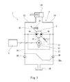
図1に、本発明の一実施形態に係る液圧駆動装置1を示す。この液圧駆動装置1は、機械ユニット2と制御装置5を含む。
FIG. 1 shows a hydraulic drive 1 according to an embodiment of the present invention. The hydraulic drive 1 includes a machine unit 2 and a controller 5.
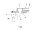
図2に示すように、機械ユニット2は、電動モータ21、ポンプ3および液圧アクチュエータ22が一体となったものである。また、機械ユニット2には、タンク29(図1参照)として、小容積の貯留室が形成されている。
As shown in FIG. 2, the machine unit 2 is one in which the electric motor 21, the pump 3 and the hydraulic actuator 22 are integrated. In the machine unit 2, a storage chamber with a small volume is formed as a tank 29 (see FIG. 1).
本実施形態では、液圧アクチュエータ22が、互いに揺動可能に連結された一対の部材71,72間の関節角度を変更する、単ロッドの液圧シリンダである。例えば、部材71,72のそれぞれは、ロボットアームである。ただし、液圧アクチュエータ22は、両ロッドの液圧シリンダであってもよい。あるいは、液圧アクチュエータ22は、液圧モータであってもよい。
In the present embodiment, the hydraulic actuator 22 is a single-rod hydraulic cylinder that changes the joint angle between the pair of members 71 and 72 that are pivotably connected to each other. For example, each of the members 71 and 72 is a robot arm. However, the hydraulic actuator 22 may be a hydraulic cylinder of both rods. Alternatively, the hydraulic actuator 22 may be a hydraulic motor.
機械ユニット2には、ポンプ3および液圧アクチュエータ22を含む液圧回路が設けられている。液圧回路を流れる作動液は、典型的には油であるが、水などのその他の液体であってもよい。
The mechanical unit 2 is provided with a hydraulic circuit including the pump 3 and the hydraulic actuator 22. The hydraulic fluid flowing through the hydraulic circuit is typically oil, but may be other liquids such as water.
ポンプ3は、電動モータ21の出力軸と連結された回転軸31を含む。つまり、ポンプ3は、電動モータ21により駆動される。なお、ポンプ3の回転軸31は、電動モータ21の出力軸と直接的に連結されてもよいし、減速機などを介して間接的に連結されてもよい。
The pump 3 includes a rotating shaft 31 connected to the output shaft of the electric motor 21. That is, the pump 3 is driven by the electric motor 21. The rotation shaft 31 of the pump 3 may be directly connected to the output shaft of the electric motor 21 or may be connected indirectly via a reduction gear or the like.
ポンプ3は、一対のポンプポート3a,3bを有する。ポンプポート3a,3bは、電動モータ21の回転方向によって吐出側と吸入側とが切り換わる。例えば、電動モータ21が一方向に回転すれば、ポンプポート3aが吸入ポート、ポンプポート3bが吐出ポートとなり、電動モータ21が逆方向に回転すれば、ポンプポート3bが吸入ポート、ポンプポート3aが吐出ポートとなる。
The pump 3 has a pair of pump ports 3a and 3b. The pump ports 3a and 3b are switched between the discharge side and the suction side depending on the rotation direction of the electric motor 21. For example, when the electric motor 21 rotates in one direction, the pump port 3a becomes the suction port and the pump port 3b becomes the discharge port, and when the electric motor 21 rotates in the reverse direction, the pump port 3b becomes the suction port and the pump port 3a It becomes a discharge port.
ポンプ3のポンプポート3a,3bは、第1給排ライン23および第2給排ライン24により液圧アクチュエータ22と接続されている。本実施形態では、液圧アクチュエータ22が単ロッドの液圧シリンダであるために、液圧アクチュエータ22への供給量と液圧アクチュエータ22からの排出量が異なる。そのために、液圧シリンダのロッド側の第1給排ライン23は、チェック弁26が設けられた第1調整ライン25によりタンク29と接続されており、液圧シリンダのヘッド側の第2給排ライン24は、パイロットチェック弁28が設けられた第2調整ライン27によりタンク29と接続されている。
The pump ports 3 a and 3 b of the pump 3 are connected to the hydraulic pressure actuator 22 by the first supply and discharge line 23 and the second supply and discharge line 24. In the present embodiment, since the hydraulic pressure actuator 22 is a single rod hydraulic cylinder, the amount supplied to the hydraulic pressure actuator 22 and the amount discharged from the hydraulic pressure actuator 22 differ. Therefore, the first supply and discharge line 23 on the rod side of the hydraulic cylinder is connected to the tank 29 by the first adjustment line 25 provided with the check valve 26, and the second supply and discharge on the head side of the hydraulic cylinder The line 24 is connected to the tank 29 by a second adjustment line 27 provided with a pilot check valve 28.
チェック弁26およびパイロットチェック弁28は、タンク29から導出される流れは許容し、その逆の流れは禁止する。さらに、第2調整ライン27に設けられたパイロットチェック弁28には、パイロットライン28aを通じて第1給排ライン23の圧力が導かれ、パイロットチェック弁28は、第1給排ライン23の圧力が設定圧よりも高くなったときに逆流防止機能を解除する。
The check valve 26 and the pilot check valve 28 allow the flow derived from the tank 29 and prohibit the reverse flow. Furthermore, the pressure of the first supply / discharge line 23 is led to the pilot check valve 28 provided in the second adjustment line 27 through the pilot line 28a, and the pressure of the first supply / discharge line 23 is set in the pilot check valve 28 Release the backflow prevention function when it becomes higher than pressure.
なお、液圧アクチュエータ22が両ロッドの液圧シリンダまたは液圧モータである場合は、第2調整ライン27にはパイロットチェック弁28の代わりに単なるチェック弁が設けられてもよい。
When the hydraulic actuator 22 is a hydraulic cylinder or a hydraulic motor of both rods, the second adjustment line 27 may be provided with a simple check valve instead of the pilot check valve 28.
ポンプ3は、可変容量型のポンプである。ポンプ3は、第1給排ライン23と第2給排ライン24との差圧が大きくなるほど当該ポンプ3の容量(1回転あたりに押しのける容積)が小さくなるように構成されている。
The pump 3 is a variable displacement pump. The pump 3 is configured such that the volume (displacement volume per one rotation) of the pump 3 decreases as the differential pressure between the first supply and discharge line 23 and the second supply and discharge line 24 increases.
本実施形態では、ポンプ3が斜板ポンプである。そして、ポンプ3の傾転角が、第1給排ライン23と第2給排ライン24の差圧に応じて自動的に切り替えられる。
In the present embodiment, the pump 3 is a swash plate pump. Then, the tilt angle of the pump 3 is automatically switched in accordance with the pressure difference between the first supply and discharge line 23 and the second supply and discharge line 24.
具体的に、ポンプ3は、図3に示すように、上述した回転軸31をベアリングを介して回転可能に支持するポートブロック44およびケーシング45を含む。そして、これらのポートブロック44およびケーシング45で囲まれる空間内に、ポートプレート43、シリンダブロック32、斜板35などが収容されている。
Specifically, as shown in FIG. 3, the pump 3 includes a port block 44 and a casing 45 which rotatably support the above-described rotating shaft 31 via a bearing. The port plate 43, the cylinder block 32, the swash plate 35 and the like are accommodated in the space surrounded by the port block 44 and the casing 45.
シリンダブロック32は、回転軸31と共に回転する。シリンダブロック32には、複数のシリンダボア41が形成されている。これらのシリンダボア41には、複数のピストン33がそれぞれ挿入されている。また、シリンダブロック32には、各シリンダボア41の底に連通路42が形成されている。
The cylinder block 32 rotates with the rotation shaft 31. A plurality of cylinder bores 41 are formed in the cylinder block 32. A plurality of pistons 33 are respectively inserted into these cylinder bores 41. Further, in the cylinder block 32, a communication passage 42 is formed at the bottom of each cylinder bore 41.
斜板35は、ピストン33のストロークを規定する。より詳しくは、ピストン33の頭部には、複数のシュー34がそれぞれ嵌合しており、これらのシュー34が、シリンダブロック32の回転に伴って斜板35上を摺動する。斜板35のシュー34側の摺動面と回転軸31に対する直交面とのなす角度が、ポンプ3の傾転角である。
The swash plate 35 defines the stroke of the piston 33. More specifically, a plurality of shoes 34 are respectively fitted to the head of the piston 33, and these shoes 34 slide on the swash plate 35 as the cylinder block 32 rotates. The angle between the sliding surface on the shoe 34 side of the swash plate 35 and the surface orthogonal to the rotation shaft 31 is the tilt angle of the pump 3.
本実施形態では、シリンダブロック32の脇に、スプリング37が配置されている。スプリング37は、斜板35とポートブロック44との間に介在し、押圧板36を介して斜板35を回転軸31の軸方向に押圧する。
In the present embodiment, a spring 37 is disposed beside the cylinder block 32. The spring 37 is interposed between the swash plate 35 and the port block 44, and presses the swash plate 35 in the axial direction of the rotation shaft 31 via the pressing plate 36.
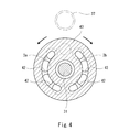
ポートプレート43は、ポートブロック44に固定されており、シリンダブロック32がポートプレート43上を摺動する。図4に示すように、ポートプレート43には、上述したポンプポート3a,3bが形成されている。シリンダブロック32に形成された連通路42は、ポンプポート3a,3bと連通したりポンプポート3a,3bから切り離されたりする。
The port plate 43 is fixed to the port block 44, and the cylinder block 32 slides on the port plate 43. As shown in FIG. 4, the port plate 43 is formed with the above-described pump ports 3a and 3b. The communication passage 42 formed in the cylinder block 32 communicates with the pump ports 3a and 3b and is separated from the pump ports 3a and 3b.
ポンプ3は、ポンプポート3a,3b間の圧力差に応じてピストン33が斜板35を傾動させるモーメントを発生させるように構成されている。本実施形態では、ポンプポート3a,3bのそれぞれが、回転軸31の中心でスプリング側と反スプリング側とに分割したときにスプリング側の部分よりも反スプリング側の部分が長くなる形状を有する。なお、説明の便宜上、以下では、回転軸31の中心からスプリング側を上方、回転軸31の中心から反スプリング側を下方という。
The pump 3 is configured to generate a moment that causes the piston 33 to tilt the swash plate 35 in accordance with the pressure difference between the pump ports 3a and 3b. In the present embodiment, each of the pump ports 3a and 3b has a shape in which the part on the non-spring side is longer than the part on the spring side when divided into the spring side and the non-spring side at the center of the rotation shaft 31. In the following, for convenience of explanation, the spring side is referred to as upward from the center of the rotary shaft 31, and the anti-spring side is referred to as downward from the center of the rotary shaft 31.
このため、ポンプポート3a,3bのどちらが吐出口となったとしても、ピストン33が斜板35の上側部分を押圧する力よりも斜板35の下側部分を押圧する力が大きくなる。逆に、吸入口では、ピストン33が斜板35の上側部分を押圧する力よりも斜板35の下側部分を押圧する力が小さくなる。従って、吐出圧が高くなるほど、換言すればポンプポート3a,3b間の圧力差が大きくなるほど、ピストン33が斜板35をスプリング37の付勢力に抗してポンプ3の傾転角が小さくなる方向に傾動させるモーメントが大きくなる。
Therefore, regardless of which of the pump ports 3a and 3b is the discharge port, the force with which the piston 33 presses the lower portion of the swash plate 35 becomes larger than the force with which the piston 33 presses the upper portion of the swash plate 35. Conversely, at the suction port, the force with which the piston 33 presses the lower portion of the swash plate 35 is smaller than the force with which the piston 33 presses the upper portion of the swash plate 35. Therefore, as the discharge pressure becomes higher, in other words, as the pressure difference between the pump ports 3a and 3b becomes larger, the piston 33 resists the biasing force of the spring 37 and the inclination angle of the pump 3 becomes smaller. The moment to tilt is increased.
上述した制御装置5は、液圧アクチュエータ22に対するアクチュエータ位置指令値に基づいて電動モータ21を制御する。例えば、制御装置5は、ROMやRAMなどのメモリとCPUを有するコンピュータであり、ROMに記憶されたプログラムがCPUにより実行される。なお、制御装置5は、単一の機器であってもよいし、複数の機器に分割されてもよい。
The control device 5 described above controls the electric motor 21 based on an actuator position command value for the hydraulic pressure actuator 22. For example, the control device 5 is a computer having a memory such as a ROM or a RAM and a CPU, and a program stored in the ROM is executed by the CPU. The control device 5 may be a single device or may be divided into a plurality of devices.
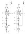
具体的に、制御装置5は、図5Aに示すように、モータ角度変換部51、位置制御部52、速度制御部53、インバータ部54および微分部55を含む。制御装置5には、図略の別の装置から、アクチュエータ位置指令値が入力される。本実施形態では、アクチュエータ位置指令値が、部材71,72間の関節角度指令値θcである。
Specifically, as shown in FIG. 5A, the control device 5 includes a motor angle conversion unit 51, a position control unit 52, a speed control unit 53, an inverter unit 54, and a differentiation unit 55. An actuator position command value is input to the control device 5 from another device (not shown). In the present embodiment, the actuator position command value is the joint angle command value θc between the members 71 and 72.
さらに、本実施形態では、制御装置5が2つのエンコーダ61,62(位置センサ)と電気的に接続されている。エンコーダ61は、図1に示すように電動モータ21の出力軸に設けられており、電動モータ21の回転角度であるモータ角度実績値θmfを検出する。エンコーダ62は、図2に示すように部材71,72同士を連結する揺動軸に設けられており、部材71,72間の関節角度実績値θfを検出する。
Furthermore, in the present embodiment, the control device 5 is electrically connected to the two encoders 61 and 62 (position sensors). The encoder 61 is provided on the output shaft of the electric motor 21 as shown in FIG. 1, and detects a motor angle actual value θmf which is a rotation angle of the electric motor 21. The encoder 62 is provided on a swing shaft connecting the members 71 and 72 to each other as shown in FIG. 2, and detects a joint angle result value θf between the members 71 and 72.
なお、関節角度実績値θfを検出する位置センサとしては、エンコーダ62以外にも、液圧アクチュエータ22である液圧シリンダに設けられるストロークセンサなどを用いることが可能である。
As the position sensor for detecting the joint angle actual value θf, it is possible to use a stroke sensor or the like provided in a hydraulic cylinder which is the hydraulic actuator 22 other than the encoder 62.
本実施形態では、制御装置5が、図5Aに示すように、関節角度指令値θcおよびエンコーダ62で検出される部材71,72間の関節角度実績値θfを用いて位置フィードバック制御を行う。また、制御装置5は、電動モータ21に対するモータ速度指令値ωmcおよびエンコーダ61で検出される電動モータ21のモータ角度実績値θmfの微分値(モータ速度実績値)ωmfを用いて速度フィードバック制御を行う。以下、制御装置5の各部の機能を詳しく説明する。
In the present embodiment, as shown in FIG. 5A, the control device 5 performs position feedback control using the joint angle command value θc and the actual joint angle value θf between the members 71 and 72 detected by the encoder 62. Control device 5 performs speed feedback control using motor speed command value ωmc for electric motor 21 and a derivative value (motor speed actual value) ωmf of motor angle actual value θmf of electric motor 21 detected by encoder 61. . Hereinafter, the functions of the respective units of the control device 5 will be described in detail.
モータ角度変換部51は、ポンプ3の傾転角と対応し、かつ部材71,72等のリンク機構に依存する減速比Rを決定し、関節角度指令値θcおよび減速比Rを使用して電動モータ21に対するモータ位置偏差θmeを算出する。
The motor angle conversion unit 51 determines the reduction ratio R corresponding to the tilt angle of the pump 3 and dependent on the link mechanism such as the members 71 and 72, and uses the joint angle command value θc and the reduction ratio R to electrically A motor position deviation θme with respect to the motor 21 is calculated.
減速比Rは、第1給排ライン23と第2給排ライン24との差圧にも依存する。例えば、モータ角度変換部51は、電動モータ21に設けられたトルク計または第1および第2給排ライン23,24に設けられた圧力計の検出値などに基づいて、減速比Rを算出する。
The reduction ratio R also depends on the pressure difference between the first supply and discharge line 23 and the second supply and discharge line 24. For example, the motor angle conversion unit 51 calculates the reduction ratio R based on the detection values of a torque meter provided in the electric motor 21 or pressure gauges provided in the first and second supply and discharge lines 23 and 24. .
そして、モータ角度変換部51は、部材71,72間の関節角度指令値θcとエンコーダ62で検出される関節角度実績値θfとの偏差を減速比Rで割って電動モータ21に対するモータ位置偏差θmeを算出する。
The motor angle conversion unit 51 divides the deviation between the joint angle command value θc between the members 71 and 72 and the actual joint angle value θf detected by the encoder 62 by the reduction ratio R to obtain the motor position deviation θme with respect to the electric motor 21. Calculate
位置制御部52は、モータ位置偏差θmeに位置ゲインKpを乗算して電動モータ21に対するモータ速度指令値ωmcを算出する。ただし、制御装置5は、モータ位置偏差θmeを算出せずに、部材71,72間の関節角度指令値θcとエンコーダ62で検出される関節角度実績値θfとの偏差にKp/Rを乗算することでモータ速度指令値ωmcを算出してもよい。
The position control unit 52 multiplies the motor position deviation θme by the position gain Kp to calculate a motor speed command value ωmc for the electric motor 21. However, the controller 5 multiplies the deviation between the joint angle command value θc between the members 71 and 72 and the actual joint angle value θf detected by the encoder 62 by Kp / R without calculating the motor position deviation θme. Thus, the motor speed command value ωmc may be calculated.
微分部55は、エンコーダ61で検出されるモータ角度実績値θmfを微分してモータ速度実績値ωmfを算出する。速度制御部53は、は、モータ速度指令値ωmcとモータ速度実績値ωmfとの偏差に速度ゲインKvを乗算して、電動モータ21に対する電流指令値Imcを算出する。インバータ部54は、電流指令値Imcに基づいて電動モータ21へ電力を供給する。
The differentiation unit 55 differentiates the motor angle actual value θmf detected by the encoder 61 to calculate the motor speed actual value ωmf. The speed control unit 53 multiplies the deviation between the motor speed command value ωmc and the motor speed actual value ωmf by the speed gain Kv to calculate the current command value Imc for the electric motor 21. The inverter unit 54 supplies power to the electric motor 21 based on the current command value Imc.
以上説明したように、本実施形態の液圧駆動装置1では、ポンプ3が、第1給排ライン23と第2給排ライン24との差圧が大きくなるほど当該ポンプ3の容量が小さくなるように構成されている。通常、液圧アクチュエータ22への作動油の供給側の給排ラインの圧力は高く、液圧アクチュエータ22からの作動液の排出側の給排ラインの圧力は低い。すなわち、第1給排ライン23と第2給排ライン24との差圧が大きいことは液圧シリンダである液圧アクチュエータ22に必要な推力が大きいことを意味する。また、ポンプ3の容量が小さいことは、減速比Rが大きいことを意味する。従って、本実施形態の液圧駆動装置1によれば、電動モータ21の回転数およびトルクが一定であっても液圧アクチュエータ22に必要な推力に応じて減速比Rを変更することができる。
As described above, in the fluid pressure drive device 1 of the present embodiment, as the differential pressure between the first supply and discharge line 23 and the second supply and discharge line 24 increases, the displacement of the pump 3 decreases. Is configured. Normally, the pressure in the supply and discharge line of the hydraulic fluid supply side to the hydraulic actuator 22 is high, and the pressure in the supply and discharge line of the hydraulic fluid discharge side from the hydraulic actuator 22 is low. That is, the fact that the differential pressure between the first supply and discharge line 23 and the second supply and discharge line 24 is large means that the thrust required for the hydraulic actuator 22 which is a hydraulic cylinder is large. Further, the fact that the displacement of the pump 3 is small means that the reduction ratio R is large. Therefore, according to the fluid pressure drive device 1 of the present embodiment, the reduction ratio R can be changed according to the thrust required for the fluid pressure actuator 22 even if the rotational speed and torque of the electric motor 21 are constant.
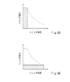
例えば、図6Aに示すように、液圧シリンダである液圧アクチュエータ22に必要な推力が大きな場合は、第1給排ライン23と第2給排ライン24との差圧が大きくなるために、減速比Rを大きくすることができる。逆に、図6Bに示すように、液圧アクチュエータ22に必要な推力が小さな場合は、第1給排ライン23と第2給排ライン24との差圧が小さくなるために、減速比Rを小さくすることができる。なお、シリンダ推力およびシリンダ速度で形成される矩形面積は、図6Aおよび6B中に示す二点鎖線に沿って変化する。
For example, as shown in FIG. 6A, when the thrust required for the hydraulic actuator 22, which is a hydraulic cylinder, is large, the differential pressure between the first supply / discharge line 23 and the second supply / discharge line 24 is large. The reduction ratio R can be increased. Conversely, as shown in FIG. 6B, when the thrust required for the hydraulic actuator 22 is small, the differential pressure between the first supply / discharge line 23 and the second supply / discharge line 24 decreases, so the reduction ratio R is set to It can be made smaller. The rectangular area formed by the cylinder thrust and the cylinder speed changes along the dashed-two dotted line shown in FIGS. 6A and 6B.
また、本実施形態では、液圧アクチュエータ22が部材71,72間の関節角度を変更する液圧シリンダであるので、液圧駆動装置1をヒューマノイドロボットや産業用ロボットなどの関節に使用することができる。
Further, in the present embodiment, since the hydraulic actuator 22 is a hydraulic cylinder that changes the joint angle between the members 71 and 72, the hydraulic drive device 1 may be used for joints such as a humanoid robot and an industrial robot. it can.
ところで、制御装置5が行う位置フィードバック制御では、エンコーダ62で検出される部材71,72間の関節角度実績値θfの代わりに、図5Bに示すように、エンコーダ61で検出される電動モータ21に対するモータ角度実績値θmfが用いられてもよい。つまり、制御装置5は、関節角度指令値θcおよび減速比Rを使用してモータ角度指令値θmcを算出し、モータ角度指令値θmcおよびモータ角度実績値θmfを用いて位置フィードバック制御を行ってもよい。ただし、前記実施形態のようにエンコーダ62で検出される部材71,72間の関節角度実績値θfを用いて位置フィードバック制御を行うことで、減速比Rが正確に決定されなかったり、液圧回路からの作動液のリークがあったとしても、液圧アクチュエータ22の作動位置を高精度に制御することができる。
By the way, in the position feedback control performed by the control device 5, as shown in FIG. 5B, the electric motor 21 detected by the encoder 61 is detected instead of the joint angle actual value θf between the members 71 and 72 detected by the encoder 62. The motor angle actual value θmf may be used. That is, the controller 5 calculates the motor angle command value θmc using the joint angle command value θc and the reduction ratio R, and performs position feedback control using the motor angle command value θmc and the motor angle actual value θmf. Good. However, by performing position feedback control using the actual joint angle value θf between the members 71 and 72 detected by the encoder 62 as in the above embodiment, the reduction ratio R may not be accurately determined, or the hydraulic circuit The operating position of the hydraulic actuator 22 can be controlled with high accuracy even if there is a leak of hydraulic fluid from the valve.
(変形例)
本発明は上述した実施形態に限定されるものではなく、本発明の要旨を逸脱しない範囲で種々の変形が可能である。 (Modification)
The present invention is not limited to the embodiments described above, and various modifications can be made without departing from the scope of the present invention.
本発明は上述した実施形態に限定されるものではなく、本発明の要旨を逸脱しない範囲で種々の変形が可能である。 (Modification)
The present invention is not limited to the embodiments described above, and various modifications can be made without departing from the scope of the present invention.
例えば、ポンプ3の傾転角は、必ずしも自動的に切り替えられる必要はなく、電動アクチュエータにより変更されてもよい。
For example, the tilt angle of the pump 3 does not necessarily have to be switched automatically, and may be changed by an electric actuator.
また、前記実施形態では、ポンプ3が斜板ポンプであったが、ポンプ3は斜軸ポンプであってもよい。あるいは、ポンプ3は、可変容量型である限り特に限定されず、例えばベーンポンプや可変容量ギアポンプなどであってもよい。ただし、前記実施形態のようにポンプ3が斜板ポンプであれば、電動モータ21、ポンプ3および液圧アクチュエータ22で構成される機械ユニット2を小型化することができる。
Moreover, in the said embodiment, although the pump 3 was a swash plate pump, the pump 3 may be a slant axis pump. Alternatively, the pump 3 is not particularly limited as long as it is of a variable displacement type, and may be, for example, a vane pump or a variable displacement gear pump. However, if the pump 3 is a swash plate pump as in the above embodiment, the mechanical unit 2 configured of the electric motor 21, the pump 3 and the hydraulic actuator 22 can be miniaturized.
また、制御装置5は、オブザーバなどの制御理論によるセンサレス制御を行ってもよい。
In addition, the control device 5 may perform sensorless control based on a control theory such as an observer.
1 液圧駆動装置
21 電動モータ
22 液圧アクチュエータ
23 第1給排ライン
24 第2給排ライン
3 ポンプ
3a,3b ポンプポート
31 回転軸
32 シリンダブロック
33 ピストン
35 斜板
37 スプリング
41 シリンダボア
43 ポートプレート
44 ポートブロック
5 制御装置
61,62 エンコーダ(位置センサ)
71,72 部材 DESCRIPTION OFSYMBOLS 1 hydraulic drive 21 electric motor 22 hydraulic actuator 23 1st feed / discharge line 24 2nd feed / discharge line 3 pump 3a, 3b pump port 31 rotating shaft 32 cylinder block 33 piston 35 swash plate 37 spring 41 cylinder bore 43 port plate 44 Port block 5 control unit 61, 62 encoder (position sensor)
71, 72 members
21 電動モータ
22 液圧アクチュエータ
23 第1給排ライン
24 第2給排ライン
3 ポンプ
3a,3b ポンプポート
31 回転軸
32 シリンダブロック
33 ピストン
35 斜板
37 スプリング
41 シリンダボア
43 ポートプレート
44 ポートブロック
5 制御装置
61,62 エンコーダ(位置センサ)
71,72 部材 DESCRIPTION OF
71, 72 members
Claims (5)
- 電動モータと、
前記電動モータによって駆動される可変容量型のポンプであって、前記電動モータの回転方向によって吐出側と吸込側とが切り換わる一対のポンプポートを有するポンプと、
第1給排ラインおよび第2給排ラインにより前記一対のポンプポートと接続された液圧アクチュエータと、
前記液圧アクチュエータに対するアクチュエータ位置指令値に基づいて前記電動モータを制御する制御装置と、を備え、
前記ポンプは、前記第1給排ラインと前記第2給排ラインとの差圧が大きくなるほど当該ポンプの容量が小さくなるように構成されている、液圧駆動装置。 Electric motor,
A pump of a variable displacement type driven by the electric motor, the pump having a pair of pump ports whose discharge side and suction side are switched according to the rotation direction of the electric motor.
A hydraulic actuator connected to the pair of pump ports by a first supply and discharge line and a second supply and discharge line;
And a controller configured to control the electric motor based on an actuator position command value for the hydraulic actuator.
The hydraulic drive system according to claim 1, wherein the pump has a smaller displacement as the differential pressure between the first supply and discharge line and the second supply and discharge line increases. - 前記ポンプは、回転軸と、前記回転軸と共に回転する、複数のシリンダボアが形成されたシリンダブロックと、前記複数のシリンダボアにそれぞれ挿入された複数のピストンと、前記一対のポンプポートが形成されたポートプレートと、前記複数のピストンのストロークを規定する斜板と、前記斜板を押圧するスプリングと、を含み、前記一対のポンプポート間の圧力差に応じて前記ピストンが前記斜板を傾動させるモーメントを発生させるように構成されている、請求項1に記載の液圧駆動装置。 The pump has a rotation shaft, a cylinder block having a plurality of cylinder bores formed therein, which rotates with the rotation shaft, a plurality of pistons respectively inserted into the plurality of cylinder bores, and a port having the pair of pump ports formed thereon A moment including a plate, a swash plate defining strokes of the plurality of pistons, and a spring pressing the swash plate, wherein the piston causes the swash plate to tilt in accordance with a pressure difference between the pair of pump ports The hydraulic drive as claimed in claim 1, wherein the hydraulic drive is configured to generate
- 前記液圧アクチュエータは、互いに揺動可能に連結された一対の部材間の関節角度を変更する液圧シリンダである、請求項1または2に記載の液圧駆動装置。 The hydraulic drive according to claim 1, wherein the hydraulic actuator is a hydraulic cylinder that changes a joint angle between a pair of members swingably connected to each other.
- 前記電動モータの回転角度であるモータ角度実績値を検出する位置センサをさらに備え、
前記制御装置は、前記ポンプの傾転角と対応する減速比を決定し、前記アクチュエータ位置指令値および前記減速比を使用して前記電動モータに対するモータ角度指令値を算出し、前記モータ角度指令値および前記位置センサで検出されるモータ角度実績値を用いて位置フィードバック制御を行う、請求項1~3の何れか一項に記載の液圧駆動装置。 It further comprises a position sensor for detecting a motor angle actual value which is a rotation angle of the electric motor,
The control device determines a reduction ratio corresponding to the tilt angle of the pump, calculates a motor angle command value for the electric motor using the actuator position command value and the reduction ratio, and the motor angle command value The hydraulic drive according to any one of claims 1 to 3, wherein position feedback control is performed using a motor angle actual value detected by the position sensor. - 前記アクチュエータ位置指令値は、前記一対の部材間の関節角度指令値であり、
前記一対の部材間の関節角度実績値を検出する位置センサをさらに備え、
前記制御装置は、前記関節角度指令値および前記位置センサで検出される関節角度実績値の検出値を用いて位置フィードバック制御を行う、請求項3に記載の液圧駆動装置。 The actuator position command value is a joint angle command value between the pair of members,
It further comprises a position sensor for detecting an actual joint angle value between the pair of members,
The hydraulic drive according to claim 3, wherein the control device performs position feedback control using the joint angle command value and a detected value of a joint angle actual value detected by the position sensor.
Priority Applications (3)
| Application Number | Priority Date | Filing Date | Title |
|---|---|---|---|
| CN201880047619.4A CN110914547B (en) | 2017-08-02 | 2018-07-31 | Hydraulic drive device |
| US16/636,077 US11137001B2 (en) | 2017-08-02 | 2018-07-31 | Hydraulic drive apparatus |
| EP18841603.6A EP3663580B1 (en) | 2017-08-02 | 2018-07-31 | Hydraulic drive apparatus |
Applications Claiming Priority (2)
| Application Number | Priority Date | Filing Date | Title |
|---|---|---|---|
| JP2017150164A JP6998145B2 (en) | 2017-08-02 | 2017-08-02 | Hydraulic drive device |
| JP2017-150164 | 2017-08-02 |
Publications (1)
| Publication Number | Publication Date |
|---|---|
| WO2019026892A1 true WO2019026892A1 (en) | 2019-02-07 |
Family
ID=65232766
Family Applications (1)
| Application Number | Title | Priority Date | Filing Date |
|---|---|---|---|
| PCT/JP2018/028612 WO2019026892A1 (en) | 2017-08-02 | 2018-07-31 | Hydraulic drive device |
Country Status (5)
| Country | Link |
|---|---|
| US (1) | US11137001B2 (en) |
| EP (1) | EP3663580B1 (en) |
| JP (1) | JP6998145B2 (en) |
| CN (1) | CN110914547B (en) |
| WO (1) | WO2019026892A1 (en) |
Families Citing this family (5)
| Publication number | Priority date | Publication date | Assignee | Title |
|---|---|---|---|---|
| CN114251256A (en) * | 2020-09-23 | 2022-03-29 | 博世力士乐(常州)有限公司 | Multi-gear pump with automatic gear control function |
| EP4108624A1 (en) * | 2021-06-24 | 2022-12-28 | Palfinger AG | Drive system |
| JP2023004126A (en) * | 2021-06-25 | 2023-01-17 | 川崎重工業株式会社 | Electric fluid pressure type robot |
| CN114294210A (en) * | 2021-12-23 | 2022-04-08 | 博世力士乐(常州)有限公司 | Multi-gear pump with delay gear switching function |
| CN116658493B (en) * | 2023-08-01 | 2023-10-24 | 华侨大学 | Negative flow system and electric engineering mechanical device based on variable rotation speed and variable displacement |
Citations (3)
| Publication number | Priority date | Publication date | Assignee | Title |
|---|---|---|---|---|
| JP2004257448A (en) | 2003-02-25 | 2004-09-16 | Shin Meiwa Ind Co Ltd | Hydraulic drive device |
| JP2008291731A (en) * | 2007-05-24 | 2008-12-04 | Kayaba Ind Co Ltd | Pump discharge rate control device |
| US20140033697A1 (en) * | 2012-07-31 | 2014-02-06 | Patrick Opdenbosch | Meterless hydraulic system having force modulation |
Family Cites Families (12)
| Publication number | Priority date | Publication date | Assignee | Title |
|---|---|---|---|---|
| US4145884A (en) | 1977-07-25 | 1979-03-27 | Childs Willard D | Reversible power transmission |
| SE437861B (en) * | 1983-02-03 | 1985-03-18 | Goran Palmers | DEVICE FOR MEDIUM HYDRAULIC CYLINDER OPERATED MACHINERY WITH ONE OF A DRIVE CELL THROUGH AN ENERGY CUMULATOR DRIVE PUMP |
| US4667472A (en) * | 1984-12-28 | 1987-05-26 | The Boeing Company | Electric integrated actuator with variable gain hydraulic output |
| JP4191430B2 (en) * | 2002-05-27 | 2008-12-03 | 三菱重工業株式会社 | Hydraulic drive device |
| JP4115994B2 (en) * | 2002-09-26 | 2008-07-09 | 日立建機株式会社 | Construction machine control device and input torque calculation method |
| JP2005054862A (en) * | 2003-08-01 | 2005-03-03 | Smc Corp | Actuator |
| JP2005308047A (en) * | 2004-04-20 | 2005-11-04 | Toyooki Kogyo Co Ltd | Hydraulic driving device |
| JP2008157276A (en) * | 2006-12-20 | 2008-07-10 | Toyota Motor Corp | Device for controlling variable displacement fluid pressure pump motor type transmission |
| JP4365870B2 (en) * | 2007-03-30 | 2009-11-18 | 三菱重工業株式会社 | Fluid pressure actuator |
| JP2009264525A (en) * | 2008-04-28 | 2009-11-12 | Nabtesco Corp | Working fluid supply device and electric actuator |
| JP2014512495A (en) * | 2011-03-07 | 2014-05-22 | ムーグ インコーポレーテッド | Underwater operating system |
| JP6593117B2 (en) * | 2015-11-13 | 2019-10-23 | 株式会社不二越 | Variable displacement piston pump input horsepower setting method |
-
2017
- 2017-08-02 JP JP2017150164A patent/JP6998145B2/en active Active
-
2018
- 2018-07-31 WO PCT/JP2018/028612 patent/WO2019026892A1/en unknown
- 2018-07-31 US US16/636,077 patent/US11137001B2/en active Active
- 2018-07-31 CN CN201880047619.4A patent/CN110914547B/en active Active
- 2018-07-31 EP EP18841603.6A patent/EP3663580B1/en active Active
Patent Citations (3)
| Publication number | Priority date | Publication date | Assignee | Title |
|---|---|---|---|---|
| JP2004257448A (en) | 2003-02-25 | 2004-09-16 | Shin Meiwa Ind Co Ltd | Hydraulic drive device |
| JP2008291731A (en) * | 2007-05-24 | 2008-12-04 | Kayaba Ind Co Ltd | Pump discharge rate control device |
| US20140033697A1 (en) * | 2012-07-31 | 2014-02-06 | Patrick Opdenbosch | Meterless hydraulic system having force modulation |
Non-Patent Citations (1)
| Title |
|---|
| See also references of EP3663580A4 |
Also Published As
| Publication number | Publication date |
|---|---|
| EP3663580A4 (en) | 2021-03-03 |
| JP6998145B2 (en) | 2022-01-18 |
| US11137001B2 (en) | 2021-10-05 |
| EP3663580A1 (en) | 2020-06-10 |
| US20200248719A1 (en) | 2020-08-06 |
| CN110914547A (en) | 2020-03-24 |
| EP3663580B1 (en) | 2023-07-05 |
| CN110914547B (en) | 2022-01-28 |
| JP2019027410A (en) | 2019-02-21 |
Similar Documents
| Publication | Publication Date | Title |
|---|---|---|
| WO2019026892A1 (en) | Hydraulic drive device | |
| US10718357B2 (en) | Hydraulic drive with rapid stroke and load stroke | |
| CN111094822B (en) | Slide valve device and slide valve | |
| JPH08226385A (en) | Variable capacity axial piston type hydraulic system | |
| KR101675659B1 (en) | Pump control apparatus | |
| JP2015529297A (en) | Design of electrohydraulic control for pump discharge pressure control | |
| JP6913527B2 (en) | Hydraulic pumps and motors | |
| US7788917B2 (en) | Method and system for feedback pressure control | |
| JP3922577B2 (en) | Double-rotating hydraulic pump device | |
| CN113454338B (en) | Hydraulic actuator with overpressure compensation | |
| JP2005320912A (en) | Variable displacement hydraulic pump | |
| JP6009770B2 (en) | Hydraulic closed circuit system | |
| JP2005308047A (en) | Hydraulic driving device | |
| US11592000B2 (en) | Servoless motor | |
| CN111794928A (en) | Axial piston machine | |
| JP2009257288A (en) | Variable displacement pump | |
| JP6550297B2 (en) | Hydraulic drive system | |
| JP6178716B2 (en) | Single rod cylinder hydraulic drive system | |
| JP2012072833A (en) | Discharge rate control device | |
| JP6695123B2 (en) | Controller for variable displacement pump | |
| JP5858893B2 (en) | Double-acting hydraulic cylinder operating structure | |
| JP2024065399A (en) | Hydraulic pump performance deterioration detection system | |
| KR20180120838A (en) | Apparatus for controlling swash plate of travel motor in construction equipment |
Legal Events
| Date | Code | Title | Description |
|---|---|---|---|
| 121 | Ep: the epo has been informed by wipo that ep was designated in this application |
Ref document number: 18841603 Country of ref document: EP Kind code of ref document: A1 |
|
| NENP | Non-entry into the national phase |
Ref country code: DE |
|
| ENP | Entry into the national phase |
Ref document number: 2018841603 Country of ref document: EP Effective date: 20200302 |