WO2019026768A1 - Machine tool control device, and machine tool - Google Patents
Machine tool control device, and machine tool Download PDFInfo
- Publication number
- WO2019026768A1 WO2019026768A1 PCT/JP2018/028117 JP2018028117W WO2019026768A1 WO 2019026768 A1 WO2019026768 A1 WO 2019026768A1 JP 2018028117 W JP2018028117 W JP 2018028117W WO 2019026768 A1 WO2019026768 A1 WO 2019026768A1
- Authority
- WO
- WIPO (PCT)
- Prior art keywords
- movement
- tool
- feed
- change point
- return
- Prior art date
Links
Images


Classifications
-
- B—PERFORMING OPERATIONS; TRANSPORTING
- B23—MACHINE TOOLS; METAL-WORKING NOT OTHERWISE PROVIDED FOR
- B23Q—DETAILS, COMPONENTS, OR ACCESSORIES FOR MACHINE TOOLS, e.g. ARRANGEMENTS FOR COPYING OR CONTROLLING; MACHINE TOOLS IN GENERAL CHARACTERISED BY THE CONSTRUCTION OF PARTICULAR DETAILS OR COMPONENTS; COMBINATIONS OR ASSOCIATIONS OF METAL-WORKING MACHINES, NOT DIRECTED TO A PARTICULAR RESULT
- B23Q15/00—Automatic control or regulation of feed movement, cutting velocity or position of tool or work
- B23Q15/20—Automatic control or regulation of feed movement, cutting velocity or position of tool or work before or after the tool acts upon the workpiece
- B23Q15/22—Control or regulation of position of tool or workpiece
- B23Q15/225—Control or regulation of position of tool or workpiece in feed control, i.e. approaching of tool or work in successive decreasing velocity steps
-
- B—PERFORMING OPERATIONS; TRANSPORTING
- B23—MACHINE TOOLS; METAL-WORKING NOT OTHERWISE PROVIDED FOR
- B23B—TURNING; BORING
- B23B1/00—Methods for turning or working essentially requiring the use of turning-machines; Use of auxiliary equipment in connection with such methods
-
- B—PERFORMING OPERATIONS; TRANSPORTING
- B23—MACHINE TOOLS; METAL-WORKING NOT OTHERWISE PROVIDED FOR
- B23Q—DETAILS, COMPONENTS, OR ACCESSORIES FOR MACHINE TOOLS, e.g. ARRANGEMENTS FOR COPYING OR CONTROLLING; MACHINE TOOLS IN GENERAL CHARACTERISED BY THE CONSTRUCTION OF PARTICULAR DETAILS OR COMPONENTS; COMBINATIONS OR ASSOCIATIONS OF METAL-WORKING MACHINES, NOT DIRECTED TO A PARTICULAR RESULT
- B23Q15/00—Automatic control or regulation of feed movement, cutting velocity or position of tool or work
- B23Q15/007—Automatic control or regulation of feed movement, cutting velocity or position of tool or work while the tool acts upon the workpiece
- B23Q15/013—Control or regulation of feed movement
-
- G—PHYSICS
- G05—CONTROLLING; REGULATING
- G05B—CONTROL OR REGULATING SYSTEMS IN GENERAL; FUNCTIONAL ELEMENTS OF SUCH SYSTEMS; MONITORING OR TESTING ARRANGEMENTS FOR SUCH SYSTEMS OR ELEMENTS
- G05B19/00—Programme-control systems
- G05B19/02—Programme-control systems electric
- G05B19/18—Numerical control [NC], i.e. automatically operating machines, in particular machine tools, e.g. in a manufacturing environment, so as to execute positioning, movement or co-ordinated operations by means of programme data in numerical form
- G05B19/19—Numerical control [NC], i.e. automatically operating machines, in particular machine tools, e.g. in a manufacturing environment, so as to execute positioning, movement or co-ordinated operations by means of programme data in numerical form characterised by positioning or contouring control systems, e.g. to control position from one programmed point to another or to control movement along a programmed continuous path
-
- G—PHYSICS
- G05—CONTROLLING; REGULATING
- G05B—CONTROL OR REGULATING SYSTEMS IN GENERAL; FUNCTIONAL ELEMENTS OF SUCH SYSTEMS; MONITORING OR TESTING ARRANGEMENTS FOR SUCH SYSTEMS OR ELEMENTS
- G05B19/00—Programme-control systems
- G05B19/02—Programme-control systems electric
- G05B19/18—Numerical control [NC], i.e. automatically operating machines, in particular machine tools, e.g. in a manufacturing environment, so as to execute positioning, movement or co-ordinated operations by means of programme data in numerical form
- G05B19/4093—Numerical control [NC], i.e. automatically operating machines, in particular machine tools, e.g. in a manufacturing environment, so as to execute positioning, movement or co-ordinated operations by means of programme data in numerical form characterised by part programming, e.g. entry of geometrical information as taken from a technical drawing, combining this with machining and material information to obtain control information, named part programme, for the NC machine
-
- G—PHYSICS
- G05—CONTROLLING; REGULATING
- G05B—CONTROL OR REGULATING SYSTEMS IN GENERAL; FUNCTIONAL ELEMENTS OF SUCH SYSTEMS; MONITORING OR TESTING ARRANGEMENTS FOR SUCH SYSTEMS OR ELEMENTS
- G05B19/00—Programme-control systems
- G05B19/02—Programme-control systems electric
- G05B19/18—Numerical control [NC], i.e. automatically operating machines, in particular machine tools, e.g. in a manufacturing environment, so as to execute positioning, movement or co-ordinated operations by means of programme data in numerical form
- G05B19/416—Numerical control [NC], i.e. automatically operating machines, in particular machine tools, e.g. in a manufacturing environment, so as to execute positioning, movement or co-ordinated operations by means of programme data in numerical form characterised by control of velocity, acceleration or deceleration
- G05B19/4163—Adaptive control of feed or cutting velocity
-
- G—PHYSICS
- G05—CONTROLLING; REGULATING
- G05B—CONTROL OR REGULATING SYSTEMS IN GENERAL; FUNCTIONAL ELEMENTS OF SUCH SYSTEMS; MONITORING OR TESTING ARRANGEMENTS FOR SUCH SYSTEMS OR ELEMENTS
- G05B2219/00—Program-control systems
- G05B2219/30—Nc systems
- G05B2219/36—Nc in input of data, input key till input tape
- G05B2219/36204—Lathe, turning
-
- G—PHYSICS
- G05—CONTROLLING; REGULATING
- G05B—CONTROL OR REGULATING SYSTEMS IN GENERAL; FUNCTIONAL ELEMENTS OF SUCH SYSTEMS; MONITORING OR TESTING ARRANGEMENTS FOR SUCH SYSTEMS OR ELEMENTS
- G05B2219/00—Program-control systems
- G05B2219/30—Nc systems
- G05B2219/50—Machine tool, machine tool null till machine tool work handling
- G05B2219/50047—Positioning, indexing
-
- Y—GENERAL TAGGING OF NEW TECHNOLOGICAL DEVELOPMENTS; GENERAL TAGGING OF CROSS-SECTIONAL TECHNOLOGIES SPANNING OVER SEVERAL SECTIONS OF THE IPC; TECHNICAL SUBJECTS COVERED BY FORMER USPC CROSS-REFERENCE ART COLLECTIONS [XRACs] AND DIGESTS
- Y02—TECHNOLOGIES OR APPLICATIONS FOR MITIGATION OR ADAPTATION AGAINST CLIMATE CHANGE
- Y02P—CLIMATE CHANGE MITIGATION TECHNOLOGIES IN THE PRODUCTION OR PROCESSING OF GOODS
- Y02P90/00—Enabling technologies with a potential contribution to greenhouse gas [GHG] emissions mitigation
- Y02P90/02—Total factory control, e.g. smart factories, flexible manufacturing systems [FMS] or integrated manufacturing systems [IMS]
Definitions
- the present invention relates to a control device of a machine tool and a machine tool.
- Patent Document 1 includes feeding means for feeding a relatively rotating tool and material, and the forward feed movement of the tool in the processing direction of the material by the tool and the reverse processing direction different from the processing direction are different.
- vibration cutting which can reciprocate the tool with respect to the material by combining the return movement and cut chips in cutting.
- the vibration cutting described in Patent Document 1 takes into consideration that the tool returns to a predetermined position according to a predetermined feed amount of the tool when the tool returns in the counter-processing direction due to the reciprocating movement of the tool. There is a problem that it is not easy to carry out cutting with vibration.
- the present invention has been made in view of the above-described circumstances, and an object of the present invention is to provide a control device for a machine tool and a machine tool capable of easily performing cutting with vibration according to a feed amount.
- the present invention firstly comprises feeding means for feeding the relatively rotating tool and material, and control means for controlling the rotation and operation of the feeding means, said control means comprising the tool Control to carry out cutting while vibrating the tool with respect to the material by combining the forward feed movement in the processing direction of the material due to and the return movement in the reverse processing direction different from the processing direction.
- a return position calculation means for calculating the return position of the tool at the time of completion of one vibration based on the number of vibrations and the feed amount predetermined for one rotation of the tool or material
- a forward feed setting hand that sets the forward feed movement based on a change point setting value that determines a change point from the machining direction to the counter-machining direction and causes the tool to reach the predetermined change point
- the calculated characterized in that it comprises a mobile setting return means for setting a pulse signal to be outputted as a command of the return movement.
- the return movement setting means sets a pulse-like signal to be output through a predetermined interval.
- the return movement setting means sets a pulse-like signal consisting of a command for moving the tool in the processing direction and a command for the return movement
- the forward movement setting means includes the return movement setting means The tool is caused to reach the change point by a combined movement of the movement in the processing direction based on the movement direction and the forward feed movement.
- the number of vibrations is one or more.
- the number of vibrations is less than one.
- the present invention can obtain the following effects.
- (1) The cutting tool can be fed together with the above-mentioned vibration by the combined movement of the forward feed movement and the return movement.
- the vibration of the cutting tool can be automatically set according to the predetermined feed amount by the return position calculation means, the forward feed setting means, and the return movement setting means, and the vibration according to the feed amount is accompanied. Cutting can be easily performed.
- a return movement command can be output as a pulse signal.
- the pulse signal can be used as a command for both the movement in the processing direction and the return movement.
- vibration cutting can be performed in which the tool or the material is vibrated once or more.
- vibration cutting can be performed in which the material or the tool is rotated by one or more rotations.
- FIG. 1 is a schematic view of a machine tool according to an embodiment of the present invention. It is a block diagram of a control device. It is a figure explaining the reciprocating movement and position of a cutting tool. It is a figure which shows the blade edge path of the nth rotation of a main axis, the n + 1st rotation, and the n + 2th rotation.
- FIG. 6 is a diagram for explaining the vibration waveform of the first embodiment.
- FIG. 5 is a diagram for explaining generation of a vibration waveform in Example 1;
- FIG. 5 is a diagram for explaining generation of a vibration waveform in Example 1;
- FIG. 5 is a diagram for explaining generation of a vibration waveform in Example 1;
- FIG. 5 is a diagram for explaining generation of a vibration waveform in Example 1;
- FIG. 5 is a diagram for explaining generation of a vibration waveform in Example 1;
- FIG. 5 is a diagram for explaining generation of a vibration waveform in Example 1;
- FIG. 5 is
- FIG. 5 is a diagram for explaining generation of a vibration waveform in Example 1;
- FIG. 6 is a diagram for explaining generation of a vibration waveform in Example 1;
- FIG. 6 is a diagram for explaining generation of a vibration waveform in Example 1;
- FIG. 7 is a diagram for explaining a vibration waveform of Example 2;
- FIG. 7 is a diagram for explaining generation of a vibration waveform in Example 2;
- FIG. 7 is a diagram for explaining generation of a vibration waveform in Example 2;
- FIG. 7 is a diagram for explaining generation of a vibration waveform in Example 2;
- FIG. 7 is a diagram for explaining generation of a vibration waveform in Example 2;
- FIG. 7 is a diagram for explaining generation of a vibration waveform in Example 2;
- FIG. 7 is a diagram for explaining generation of a vibration waveform in Example 2;
- FIG. 7 is a diagram for explaining generation of a vibration waveform in Example 2;
- FIG. 7 is a diagram for explaining generation of a vibration
- FIG. 7 is a diagram for explaining generation of a vibration waveform in Example 2;
- FIG. 7 is a diagram for explaining a vibration waveform of Example 3;
- FIG. 7 is a diagram for explaining a vibration waveform of Example 3;
- FIG. 7 is a diagram for explaining a vibration waveform of Example 3;
- the machine tool 100 includes a spindle 110, a cutting tool 130 such as a cutting tool for machining a workpiece W, and a control device 180.
- a chuck 120 is provided at the tip of the spindle 110, and the workpiece W is held by the spindle 110 via the chuck 120.
- the spindle 110 is rotatably supported by the spindle stock 110A, and is rotated by the power of a spindle motor (for example, a built-in motor) provided between the spindle stock 110A and the spindle 110, for example.
- the headstock 110 ⁇ / b> A is installed in the Z-axis direction feeding mechanism 160.
- the Z-axis direction feed mechanism 160 includes a base 161 integral with the bed, and a Z-axis direction guide rail 162 slidably supporting the Z-axis direction feed table 163.
- the linear servomotor 165 has a mover 165a and a stator 165b.
- the mover 165a is provided on the Z-axis direction feed table 163, and the stator 165b is provided on the base 161.
- the cutting tool 130 is mounted on the tool stand 130 A, and the tool stand 130 A is installed on the X-axis direction feed mechanism 150.
- the X-axis direction feed mechanism 150 includes a base 151 integral with the bed, and an X-axis direction guide rail 152 slidably supporting the X-axis direction feed table 153.
- the X-axis direction feed table 153 moves along the X-axis direction orthogonal to the Z-axis direction shown by the drive of the linear servomotor 155, the tool base 130A moves in the X-axis direction.
- the linear servomotor 155 has a mover 155 a and a stator 155 b.
- the mover 155 a is provided on the X-axis direction feed table 153, and the stator 155 b is provided on the base 151.
- the Y-axis direction feed mechanism may be provided in the machine tool 100.
- the Y-axis direction is a direction orthogonal to the illustrated Z-axis direction and the X-axis direction.
- the Y-axis direction feeding mechanism may have the same structure as the Z-axis direction feeding mechanism 160 or the X-axis direction feeding mechanism 150.
- the cutting tool 130 can be moved in the Y-axis direction in addition to the X-axis direction by a combination of the X-axis direction feeding mechanism 150 and the Y-axis direction feeding mechanism.
- the Z-axis direction feeding mechanism 160 has been described using an example using a linear servomotor, a known ball screw and servomotor may be used.
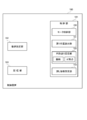
- the control device 180 includes a control unit 181, a numerical value setting unit 182, and a storage unit 183, which are connected via a bus.
- the control unit 181 includes a CPU or the like, loads various programs and data stored in, for example, the ROM of the storage unit 183 into the RAM, and executes the program. Thereby, the operation of the machine tool 100 can be controlled based on the program.
- the controller 181 is capable of controlling the rotation of the main shaft 110 and the feed of the Z-axis direction feed mechanism 160, and has a motor controller 190 that controls the operation of each motor.
- the control device 180 drives the spindle motor to rotate the workpiece W relative to the cutting tool 130, and drives the Z-axis direction feed mechanism 160 to rotate the workpiece W relative to the cutting tool 130 along the Z axis.
- the cutting tool 130 is moved in the X-axis direction with respect to the workpiece W by driving the X-axis direction feeding mechanism 150.
- the cutting tool 130 is moved relative to the work W by relative movement between the cutting tool 130 and the work W, and the cutting tool 130 is fed to the work W in a predetermined processing feed direction, and the work W is machined by the cutting tool 130 can do.
- the control device 180 moves the cutting tool 130 with respect to the work W along the processing feed direction by a predetermined advancing amount toward the processing direction which is the advancing direction of the processing feed (forward movement)
- the Z-axis direction feeding mechanism 160 or the X-axis direction feeding mechanism 150 is driven to move so as to move (return) by a predetermined amount of retraction toward the opposite machining direction opposite to the machining direction.
- the control unit 181 causes the cutting tool 130 to reciprocate and vibrate by the movement of the headstock 110A or the tool stand 130A by the movement drive of the Z-axis direction feeding mechanism 160 or the X-axis direction feeding mechanism 150, thereby advancing amount and retraction amount Can be sent to the work W by the difference (progressive amount).
- the circumferential surface of the workpiece W is processed into a wave according to the phase of the spindle 110.
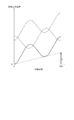
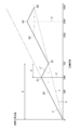
- FIG. 4 shows an example in which the number of reciprocating movements of the cutting tool 130 in one rotation of the workpiece W is the number of vibrations D, and the number of vibrations D is 1.5 (times / r).
- a virtual line (one-dot chain line) passing through the valley of the wavelike waveform is a feed straight line indicating the feed amount, and the position of the main spindle phase 360 ° in the feed straight line corresponds to the feed amount F per workpiece W rotation.
- the edge path of the cutting tool 130 at the nth rotation of the spindle 110 (work W) (indicated by a solid line in FIG. 4) and the edge path at the n + 1th rotation (indicated by a broken line in FIG. 4) are shifted in the spindle phase direction (horizontal axis direction of the graph in FIG. 4), and an overlap occurs in the cutting edge path of the cutting tool 130 at the time of cutting.
- the cutting tool 130 and the workpiece W do not contact in the processing feed direction During the idle period in which the cutting tool 130 substantially does not cut the workpiece W, chips generated on the workpiece W are divided into chips.
- the workpiece W can be smoothly processed while dividing chips by vibration cutting processing in which the workpiece W is processed by the cutting tool 130 while accompanied by vibration due to reciprocating movement of the cutting tool 130 with respect to the workpiece W.
- the nth blade edge path and the n + 1 blade edge path are reversed by 180 °.
- the nth blade edge path and the n + 1 blade edge path do not have to coincide (in phase), and the nth blade edge path and the n + 1 blade edge path may be deviated in the main shaft phase direction.
- the feed amount F is increased while maintaining the amplitude size constant, the period in which the blade edge path of the n + 1th rotation is included in the blade edge path of the nth rotation decreases, and the blade edge path of the n + 1th rotation is n rotations If it does not reach the blade edge path of the eye, the idle period will not occur.
- the control unit 181 sets the feed amount F so that an idle period occurs. It is configured to set the amplitude of the vibration waveform in proportion. At the time of cutting, the spindle rotational speed and the feed amount F are designated in advance by designation in a machining program or the like.
- the control unit 181 is configured to set the amplitude to Q * F by multiplying the feed amount F by the amplitude feed ratio Q, with the ratio of the amplitude to the feed amount F as the amplitude feed ratio Q.
- the amplitude feed ratio Q can be designated as a value (argument Q) following Q, for example, in a machining program.
- the number of vibrations D can also be designated by a value (argument D) following D in the machining program.
- the control unit 181 has a return position calculation unit 191, a forward feed setting unit 192, and a return movement setting unit 193 in order to move the cutting tool 130 with respect to the workpiece W while vibrating it.
- the control unit 181 corresponds to the control unit of the present invention
- the return position calculation unit 191, the forward feed setting unit 192, and the return movement setting unit 193 include the return position calculation unit, forward feed setting unit, and return movement setting of the present invention. Each corresponds to the means.
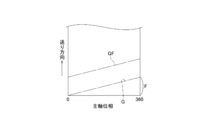
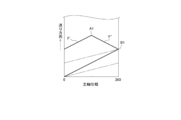
- a straight line of feed is determined.
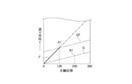
- the straight line of this feed is referred to as a substantial feed line G, and when the number of vibrations D is 1.5 (times / r), the phase of the main shaft 110 is taken as the horizontal axis direction and the machining of the cutting tool 130 is performed. It is shown by a dashed dotted line in FIG. 5 of a graph in which the position in the feed direction is taken as the vertical axis.
- the cutting tool 130 substantially reaches the feed line G when one vibration is completed, switches from the return to the forward movement, and vibrates 1.5 times in one rotation of the work W, that is, three times in two rotations of the work W To the work W.
- the return position calculation unit 191 calculates, based on the number of vibrations D and the feed amount F, the position on the substantial feed line G at which the cutting tool 130 is located at the completion of one vibration as the return position.
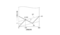
- FIG. 5 shows return positions in three vibrations as direction change points B1, B2 and B3 which switch from the backward movement to the forward movement.
- the return position of the cutting tool 130 at the time of completion of one vibration is on the substantial feed line G indicated by a dashed dotted line in FIG. 6A.
- the spindle phase at the return position of the cutting tool 130 is a phase obtained by multiplying an angle (360 °) for one rotation of the work W by an inverse number (2/3) of the number of times of vibration D.
- the change point B1 is at the position of the principal axis phase 240 °.
- each change point is a position on the substantial feed line G with one interval as a value obtained by multiplying an angle for one rotation of the work W by the reciprocal of the number of vibrations D, and in the case of this embodiment
- the change point B2 of is at the position of the main axis phase 480 °
- the change point B3 is at the position of the main axis phase 720 °.
- the return position calculation unit 191 can calculate each return position based on the feed amount F and the number of vibrations D.
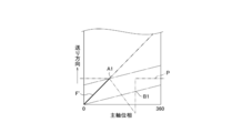
- the direction change point A1 at which the forward movement is switched to the backward movement is a straight line (amplitude line QF) is on.
- the main-spindle phase of the change point A1 is a phase (120) obtained by multiplying the main-spindle phase 240 ° of the change point B1 by the reciprocal (1/2) of the numerator of the reciprocal (2/3) of the vibration frequency D °).
- the change point A1 is set from the intersection of the amplitude line QF and the vertical line passing through the main axis phase 120 °.
- each change point A becomes a position on the amplitude line QF, with one interval being a value obtained by multiplying an angle between adjacent change points B by 1 ⁇ 2.
- the change point A2 is It is located at a half value (spindle phase 360 °) from the spindle phase 240 ° at which the change point B1 is to the spindle phase 480 ° at which the change point B2 is, and the change point A3 is the spindle phase 480 at the change point B2. It is located at a half value (spindle phase 540 °) of the spindle phase 720 ° at which the change point B3 is reached.
- the change point A1 is determined using the feed amount F, the amplitude feed ratio Q, and the number of vibrations D as parameters (change point set value).
- the forward feed setting unit 192 sets a straight line passing through the spindle phase 0 ° and the change point A1 as forward feed movement, and the control unit 181 outputs a forward feed command for moving the blade edge along the forward feed movement.
- the return movement setting unit 193 is configured to output a movement command for moving the cutting tool 130 in the opposite processing direction as a pulse signal P at a predetermined interval.
- the pulse signal P is fed in the feed direction (vertically of the graph in FIG. 6C) so that the cutting edge returns from the change point A1 to the change point B1.
- a downward convex waveform (indicated by a two-dot chain line in the drawing) which is opposite to the axial direction) is set as a signal to be output as a movement command for moving in the opposite direction.
- the pulse signal P By the pulse signal P, a return movement is performed in which the cutting edge periodically moves in the counter-processing direction.
- the magnitude of the convex shape of the pulse signal P can be determined according to the distance between A1 and B1 viewed in the feed direction, and the return movement setting unit 193 determines the cutting edge by the combined movement of the forward movement movement and the return movement. As shown in FIG. 6D, it is configured to include a pulse signal P that is set to perform a return movement F ′ ′ connecting the change point A1 and the change point B1.
- the pulse signal of the movement command to be moved in the counter-processing direction which is a periodic pulse-like command by the return movement setting unit 193, has a cycle in which the backward movement F ′ ′ is started from each change point A
- the cutting edge moves from the change point A1 to the change point B1 (position of the main spindle phase 240 °) by the movement command in the opposite direction (the downward convex portion of the pulse signal) at the timing of the main spindle phase 120 °. Perform a return F ".
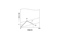
- the blade edge simply moves from the change point B to the change point A along the forward feed movement, as shown in FIG. 7A, when the return movement setting unit 193 does not instruct the movement in the reverse processing direction.
- a forward movement F ' is performed from the change point B1 to the change point A2 (position of the spindle phase of 360 °). Then, the movement in the reverse machining direction is commanded at the timing of the main spindle phase 360 °, and a backward movement F ′ ′ passing through the change point A2 and the change point B2 (position of the main spindle phase 480 °) is performed.
- the point B2 matches, the chip is cut off due to the idling operation.
- the cutting tool 130 can be fed with the above-mentioned vibration by the combined movement of the forward feed movement and the return movement.
- the vibration of the cutting tool 130 can be automatically set according to the feed amount F determined in advance by the return position calculation unit 191, the forward feed setting unit 192, and the return movement setting unit 193. It is possible to easily perform cutting with the corresponding vibration.
- the number of vibrations D can be set to less than one.
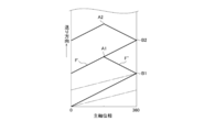
- FIG. 8 shows an example in which the number of vibrations D is 0.5 (times / r).
- the spindle rotational speed and the feed amount F are designated in advance by designation in the machining program or the like.
- a substantial feed line G is determined (shown by a one-dot chain line in FIG. 8). The cutting tool 130 arrives on the substantial feed line G when one vibration is completed, and switches from return to forward movement.
- the amount of spindle rotation during forward and backward movement of the cutting tool 130 is defined as the amount of spindle rotation E per tool vibration. Further, the spindle rotation amount while the cutting tool 130 retracts, in other words, the spindle rotation amount required to reach the feed line G substantially from the point when the cutting tool 130 switches from the forward movement to the backward movement, Let it be the spindle rotation amount R at the time of backward movement (at the time of backward movement).
- the return position calculation unit 191 calculates, as a return position, the position of the main spindle phase corresponding to the main spindle rotation amount E on the feed line G based on the main spindle rotation amount E and the feed amount F at the time of one vibration completion.
- FIG. 8 shows return positions in two vibrations as direction change points B1 and B2 at which the return movement is switched to the forward movement.
- the return position of the cutting tool 130 at the time of one vibration completion is an angle (360 °) for one rotation of the main spindle on the substantial feed line G shown by a dashed dotted line in FIG. Is at the position of the spindle phase obtained by multiplying the spindle rotation amount E by.
- the change point B1 is at the position of the principal axis phase 720 °.
- each change point is a position on the substantial feed line G with an interval of two rotations of the work W being one interval, and in the case of the present embodiment, the change point B2 on the substantial feed line G is the main shaft phase 1440 ° In position.
- the return position calculation unit 191 can calculate each return position based on the spindle rotation amount E and the feed amount F when one vibration is completed.
- the spindle rotation amount R at the time of backward movement is 0.5 (rotation), and a rotation of 180 ° is required from the start to the end of the backward movement. Therefore, as shown in FIG. 9B, the direction change point A1 at which the forward movement returns to the backward movement returns the spindle phase (540 °) which is equivalent to the spindle rotation amount R from the spindle phase (720 °) at the return position. It is in.
- the forward path feed setting unit 192 sets a line C of the main spindle phase 540 ° as the axis of symmetry and a point that is line symmetrical with respect to the change point B1.
- the symmetry point B1 ' is set, the straight line passing through the spindle phase 0 ° and the symmetry point B1' is set as the forward feed movement, and the control unit 181 outputs a forward feed command for moving the blade edge along the forward feed movement.
- the change point A1 is at a position of the main axis phase 540 ° on a straight line passing through the main axis phase 0 ° and the symmetry point B1 ′, in other words, the change point A1 is the feed amount F, at the time of retraction.
- the spindle rotation amount R and the spindle rotation amount E at the time of completion of one vibration are determined as parameters (change point setting value), and the forward feed setting unit 192 sets the forward movement based on the change point setting.
- each change point A is at the position of the main spindle phase for each angle according to the main shaft rotation amount E at the time of one vibration completion, so each symmetrical point B ′ is the change point A corresponding to each change point B.
- the line of the main axis phase is defined as an axis of symmetry, and is defined as a point that is line symmetrical with respect to each change point B.
- the symmetry point B2 ' is at a position 360 ° before the principal axis phase 1440 ° at which the change point B2 occurs (position of the principal axis phase 1080 °).
- the change point A2 is a change point B2
- the pulse signal P of the movement command to be moved in the opposite processing direction becomes a periodic pulse-like command of the return movement setting unit 193.
- the size of the convex shape of the pulse signal P can be determined according to the distance between A1 and B1 viewed in the feed direction.
- the return movement setting unit 193 sets a pulse signal to perform a reverse movement F ′ ′ connecting the change point A1 and the change point B1 by the combined movement of the forward feed movement and the return movement. It is configured with P.
- the pulse signal has a cycle in which the backward movement F ′ ′ is started from each change point A, and at the timing of the main spindle phase 540 °, the cutting edge instructs movement in the reverse processing direction (the pulse signal is convex downward Depending on the part of the shape), the backward movement F ′ ′ from the change point A1 to the change point B1 (position of the main spindle phase 720 °) is performed.
- the chips are cut by the fact that the backward movement F ′ ′ crosses the forward movement F ′ at the change point B1.
- the cutting tool 130 can be fed with the above-mentioned vibration by the combined movement of the forward feed movement and the return movement.
- the vibration of the cutting tool 130 can be automatically set according to the feed amount F determined in advance by the return position calculation unit 191, the forward feed setting unit 192, and the return movement setting unit 193. It is possible to easily perform cutting with the corresponding vibration.
- the present invention is not limited to this example.
- the spindle 110 when the spindle 110 is rotated to feed the cutting tool 130 in the Z-axis direction or when the cutting tool 130 is rotated to feed the spindle 110 in the Z-axis direction, the spindle 110 is fixed and the cutting tool 130 is rotated.
- the Z-axis direction feeding mechanism corresponds to the feeding means of the present invention.
- the spindle rotation amount E per tool vibration of the second embodiment may be set not only to an integral number of rotations such as 2 rotations and 3 rotations, but also to a number corresponding to a rotation angle exceeding 1 rotation (360 degrees). it can.
- the pulse signal P of the return movement setting unit 193 repeats a command to move the cutting tool 130 in the processing direction to the spindle phase at the change point A and a command to move the cutting tool 130 in the reverse processing direction from the spindle phase at the change point A. It can also be a signal.
- the forward feed setting unit 192 moves the cutting edge in the processing direction based on the pulse signal P (moves in the processing direction by a command to move the change point A in the processing direction to the main spindle phase) and a predetermined forward feed command
- the forward feed movement can be set so that the combined movement with the movement in the processing direction by the above becomes the forward feed movement.
- the predetermined forward feed command can be, for example, a forward feed command for moving the cutting edge substantially onto the feed line G.
- FIG. 11A shows an example where the number of vibrations D is 0.5 (times / r).
- a substantial feed line G is determined (indicated by a dot-and-dash line in the figure, which corresponds to the feed line of the tool of the present invention).
- the return position (change point B1) on the substantial feed line G is calculated.
- the spindle rotation amount R at the time of backward movement of the cutting tool 130 (at the time of backward movement) is 0.5 (rotation)
- the direction change point A1 at which the forward movement is switched to the backward movement is at the main shaft phase 540 °.
- the predetermined forward feed command is a forward feed command for moving the cutting edge on the feed line G substantially, as shown in FIG. 11B, at the position of the main spindle phase 540 °, between the feed line G and the change point A1.
- the pulse signal P has an upwardly convex waveform (FIG. 11C) which is forwardly directed in the feed direction (the direction of the vertical axis of the graph in FIG. 11B) so as to return to the feed line G substantially after obtaining this position shift C ′. (Indicated by a two-dot chain line).
- the forward feed setting unit 192 moves in the processing direction according to a command to move in the processing direction up to the spindle phase 540 ° of the change point A1, and moves in the processing direction determined by the feed amount F (substantially The combined movement with the line G) is referred to as forward movement (indicated by F ').
- the pulse signal P has a cycle in which a straight line passing from the main spindle phase 0 ° and the symmetry point B1 'is started from the main spindle phase 0 °, and the cutting edge has the main spindle phase at the timing of the main spindle phase 0 °.
- a forward movement F 'from 0 ° to the change point A1 is performed, and a return movement F "from the change point A1 on the forward movement F' is performed at the timing of the main axis phase 540 °.
- a command to move in the processing direction from the main spindle phase to the main spindle phase at the change point A and a command to move in the reverse processing direction from the main spindle phase at the change point A to the main spindle phase at the change point B are repeated.
- the movement in the processing direction by the command to move the pulse signal P in the processing direction and the movement in the processing direction by the forward feed command can be any movement if it is forward feed movement by combining them, but the forward path
- the feed command is a forward feed command to move the cutting edge onto the feed line G
- the feed line G is a feed amount F at a general cutting process (conventional cutting) without the accompanying vibration. Since it becomes the same as the line which becomes settled, forward movement F 'can be obtained by adding pulse signal P to conventional cutting.
- the change point A1 is described based on the feed amount F, the spindle rotation amount R at reverse, and the spindle rotation amount E at the completion of one vibration, but the pulse signal P changes at the change point A1.
- the present invention is also applicable to the case where the feed amount F, the amplitude feed ratio Q, and the number of vibrations D are determined.
Abstract
Provided are a machine tool control device and a machine tool that can easily perform cutting work that is accompanied by vibrations in accordance with a feed quantity. A machine tool control device (180) comprising a control unit (181) that controls a feed action and a relative rotation of a tool and a material, wherein the control unit combines an outbound feed movement and a return movement, said outbound feed movement being in a work direction of the material by the tool and said return movement being in a reverse work direction, and thus performs control such that cutting work is performed while the tool is made to move in relation to the material. Also provided are: a return position calculation unit (191) that, on the basis of a number of vibrations and a feed quantity that are predetermined for one rotation of either the tool or the material, calculates a return position of the tool when one vibration is complete; an outbound feed setting unit (192) that sets the outbound feed movement on the basis of a change point setting value determining a change point from the work direction to the reverse work direction, and causes the tool to arrive at the determined change point; and a return movement setting unit (193) that sets a pulse signal, said pulse signal being outputted as a return movement command, such that the tool arrives at the calculated return position when one vibration is complete.
Description
本発明は、工作機械の制御装置および工作機械に関する。
The present invention relates to a control device of a machine tool and a machine tool.
例えば特許文献1には、相対的に回転する工具と材料とを送り動作させる送り手段を備え、前記工具による前記材料の加工方向への往路送り移動と前記加工方向とは異なる反加工方向への戻し移動とを合成することによって、前記工具を前記材料に対して往復移動させ、切削加工に際して切屑を分断することができる振動切削加工の技術が開示されている。
For example, Patent Document 1 includes feeding means for feeding a relatively rotating tool and material, and the forward feed movement of the tool in the processing direction of the material by the tool and the reverse processing direction different from the processing direction are different. There is disclosed a technique of vibration cutting which can reciprocate the tool with respect to the material by combining the return movement and cut chips in cutting.
特許文献1に記載の振動切削加工は、前記工具の往復移動により、前記工具が反加工方向に戻る際、予め定められる工具の送り量に応じた所定の位置に前記工具が戻ることを考慮して前記振動を伴う切削加工を行うことは容易ではないという問題点があった。
The vibration cutting described in Patent Document 1 takes into consideration that the tool returns to a predetermined position according to a predetermined feed amount of the tool when the tool returns in the counter-processing direction due to the reciprocating movement of the tool. There is a problem that it is not easy to carry out cutting with vibration.
本発明は、上述のような実情に鑑みてなされたもので、送り量に応じた振動を伴う切削加工を容易に行える工作機械の制御装置および工作機械を提供することを目的とする。
The present invention has been made in view of the above-described circumstances, and an object of the present invention is to provide a control device for a machine tool and a machine tool capable of easily performing cutting with vibration according to a feed amount.
本発明は、第1に、相対的に回転する工具と材料とを送り動作させる送り手段と、前記回転と前記送り手段の動作とを制御する制御手段とを備え、該制御手段が、前記工具による前記材料の加工方向への往路送り移動と前記加工方向とは異なる反加工方向への戻し移動とを合成することによって、前記材料に対して前記工具を振動させながら切削加工を行うように制御を行う工作機械の制御装置において、前記工具あるいは材料の、1回転に対して予め定められる振動回数および送り量に基づいて、1振動完了時における前記工具の戻り位置を算出する戻り位置算出手段と、前記加工方向から前記反加工方向への変化点を定める変化点設定値に基づいて前記往路送り移動を設定し、前記工具を前記定めた変化点に到達させる往路送り設定手段と、1振動完了時の前記工具が前記算出した戻り位置に到達するように、前記戻し移動の指令として出力されるパルス状の信号を設定する戻し移動設定手段とを備えることを特徴とする。
The present invention firstly comprises feeding means for feeding the relatively rotating tool and material, and control means for controlling the rotation and operation of the feeding means, said control means comprising the tool Control to carry out cutting while vibrating the tool with respect to the material by combining the forward feed movement in the processing direction of the material due to and the return movement in the reverse processing direction different from the processing direction. And a return position calculation means for calculating the return position of the tool at the time of completion of one vibration based on the number of vibrations and the feed amount predetermined for one rotation of the tool or material, A forward feed setting hand that sets the forward feed movement based on a change point setting value that determines a change point from the machining direction to the counter-machining direction and causes the tool to reach the predetermined change point When, as 1 said tool during vibration completion reaches the return position the calculated, characterized in that it comprises a mobile setting return means for setting a pulse signal to be outputted as a command of the return movement.
第2に、前記戻し移動設定手段は、所定のインターバルを介して出力されるパルス状の信号を設定することを特徴とする。
Secondly, the return movement setting means sets a pulse-like signal to be output through a predetermined interval.
第3に、前記戻し移動設定手段は、前記加工方向に工具を移動させる指令と、前記戻し移動の指令とからなるパルス状の信号を設定し、前記往路送り設定手段は、前記戻し移動設定手段に基づく前記加工方向への移動と、前記往路送り移動との合成移動によって、前記工具を前記変化点に到達させることを特徴とする。
Thirdly, the return movement setting means sets a pulse-like signal consisting of a command for moving the tool in the processing direction and a command for the return movement, and the forward movement setting means includes the return movement setting means The tool is caused to reach the change point by a combined movement of the movement in the processing direction based on the movement direction and the forward feed movement.
第4に、前記振動回数が1以上であることを特徴とする。
Fourth, the number of vibrations is one or more.
第5に、前記振動回数が1未満であることを特徴とする。
Fifth, the number of vibrations is less than one.
第6に、上記いずれかの工作機械の制御装置を備えた工作機械であることを特徴とする。
Sixth, it is a machine tool provided with any one of the above-described machine tool control devices.
本発明は以下の効果を得ることができる。
(1)切削工具を、往路送り移動と戻し移動との合成移動によって前記振動を伴いながら送ることができる。特に戻り位置算出手段、往路送り設定手段、戻し移動設定手段により、切削工具の前記振動を、予め定められる送り量に応じて自動的に設定することができ、送り量に応じた前記振動を伴う切削加工を容易に行うことができる。 The present invention can obtain the following effects.
(1) The cutting tool can be fed together with the above-mentioned vibration by the combined movement of the forward feed movement and the return movement. Particularly, the vibration of the cutting tool can be automatically set according to the predetermined feed amount by the return position calculation means, the forward feed setting means, and the return movement setting means, and the vibration according to the feed amount is accompanied. Cutting can be easily performed.
(2)戻し移動の指令をパルス状の信号で出力できる。
(2) A return movement command can be output as a pulse signal.
(3)パルス状の信号を、加工方向への移動と戻し移動の双方の移動に対する指令とすることができる。
(3) The pulse signal can be used as a command for both the movement in the processing direction and the return movement.
(4)材料あるいは工具の1回転で、工具あるいは材料を1回以上振動させる振動切削を行うことができる。
(4) In one rotation of the material or the tool, vibration cutting can be performed in which the tool or the material is vibrated once or more.
(5)工具あるいは材料の1振動で、材料あるいは工具を1回転以上回転させる振動切削を行うことができる。
(5) In one vibration of the tool or the material, vibration cutting can be performed in which the material or the tool is rotated by one or more rotations.
(6)送り量に応じた振動を伴う切削加工を容易に行える工作機械を提供することができる。
(6) It is possible to provide a machine tool that can easily perform cutting with vibrations according to the feed amount.
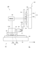
以下、図面を参照しながら本発明の工作機械の制御装置および工作機械について説明する。図1に示すように、工作機械100は、主軸110と、ワークWを加工するバイト等の切削工具130と、制御装置180とを備えている。
主軸110の先端にはチャック120が設けられており、ワークWはチャック120を介して主軸110に保持されている。主軸110は、主軸台110Aに回転自在に支持され、例えば主軸台110Aと主軸110との間に設けられた主軸モータ(例えばビルトインモータ)の動力によって回転する。主軸台110AはZ軸方向送り機構160に設置されている。 Hereinafter, a control device for a machine tool and a machine tool according to the present invention will be described with reference to the drawings. As shown in FIG. 1, themachine tool 100 includes a spindle 110, a cutting tool 130 such as a cutting tool for machining a workpiece W, and a control device 180.
Achuck 120 is provided at the tip of the spindle 110, and the workpiece W is held by the spindle 110 via the chuck 120. The spindle 110 is rotatably supported by the spindle stock 110A, and is rotated by the power of a spindle motor (for example, a built-in motor) provided between the spindle stock 110A and the spindle 110, for example. The headstock 110 </ b> A is installed in the Z-axis direction feeding mechanism 160.
主軸110の先端にはチャック120が設けられており、ワークWはチャック120を介して主軸110に保持されている。主軸110は、主軸台110Aに回転自在に支持され、例えば主軸台110Aと主軸110との間に設けられた主軸モータ(例えばビルトインモータ)の動力によって回転する。主軸台110AはZ軸方向送り機構160に設置されている。 Hereinafter, a control device for a machine tool and a machine tool according to the present invention will be described with reference to the drawings. As shown in FIG. 1, the
A
Z軸方向送り機構160は、ベッドと一体のベース161と、Z軸方向送りテーブル163をスライド自在に支持するZ軸方向ガイドレール162とを備えている。Z軸方向送りテーブル163が、リニアサーボモータ165の駆動によって、ワークWの回転軸線方向に一致する図示のZ軸方向に沿って移動すると、主軸台110AがZ軸方向に移動する。リニアサーボモータ165は可動子165aおよび固定子165bを有し、可動子165aはZ軸方向送りテーブル163に設けられ、固定子165bはベース161に設けられている。
The Z-axis direction feed mechanism 160 includes a base 161 integral with the bed, and a Z-axis direction guide rail 162 slidably supporting the Z-axis direction feed table 163. When the Z-axis direction feed table 163 is moved by the drive of the linear servomotor 165 along the illustrated Z-axis direction which coincides with the rotational axis direction of the workpiece W, the headstock 110A moves in the Z-axis direction. The linear servomotor 165 has a mover 165a and a stator 165b. The mover 165a is provided on the Z-axis direction feed table 163, and the stator 165b is provided on the base 161.
切削工具130は工具台130Aに装着され、工具台130Aは、X軸方向送り機構150に設置される。
X軸方向送り機構150は、ベッドと一体のベース151と、X軸方向送りテーブル153をスライド自在に支持するX軸方向ガイドレール152とを備えている。X軸方向送りテーブル153が、リニアサーボモータ155の駆動によって図示のZ軸方向に対して直交するX軸方向に沿って移動すると、工具台130AがX軸方向に移動する。リニアサーボモータ155は可動子155aおよび固定子155bを有し、可動子155aはX軸方向送りテーブル153に設けられ、固定子155bはベース151に設けられている。
Y軸方向送り機構を工作機械100に設けてもよい。Y軸方向は図示のZ軸方向およびX軸方向に直交する方向である。Y軸方向送り機構は、Z軸方向送り機構160またはX軸方向送り機構150と同様の構造とすることができる。従来公知のようにX軸方向送り機構150とY軸方向送り機構の組み合わせにより、切削工具130をX軸方向に加えてY軸方向にも移動させることができる。 Thecutting tool 130 is mounted on the tool stand 130 A, and the tool stand 130 A is installed on the X-axis direction feed mechanism 150.
The X-axisdirection feed mechanism 150 includes a base 151 integral with the bed, and an X-axis direction guide rail 152 slidably supporting the X-axis direction feed table 153. When the X-axis direction feed table 153 moves along the X-axis direction orthogonal to the Z-axis direction shown by the drive of the linear servomotor 155, the tool base 130A moves in the X-axis direction. The linear servomotor 155 has a mover 155 a and a stator 155 b. The mover 155 a is provided on the X-axis direction feed table 153, and the stator 155 b is provided on the base 151.
The Y-axis direction feed mechanism may be provided in themachine tool 100. The Y-axis direction is a direction orthogonal to the illustrated Z-axis direction and the X-axis direction. The Y-axis direction feeding mechanism may have the same structure as the Z-axis direction feeding mechanism 160 or the X-axis direction feeding mechanism 150. As is conventionally known, the cutting tool 130 can be moved in the Y-axis direction in addition to the X-axis direction by a combination of the X-axis direction feeding mechanism 150 and the Y-axis direction feeding mechanism.
X軸方向送り機構150は、ベッドと一体のベース151と、X軸方向送りテーブル153をスライド自在に支持するX軸方向ガイドレール152とを備えている。X軸方向送りテーブル153が、リニアサーボモータ155の駆動によって図示のZ軸方向に対して直交するX軸方向に沿って移動すると、工具台130AがX軸方向に移動する。リニアサーボモータ155は可動子155aおよび固定子155bを有し、可動子155aはX軸方向送りテーブル153に設けられ、固定子155bはベース151に設けられている。
Y軸方向送り機構を工作機械100に設けてもよい。Y軸方向は図示のZ軸方向およびX軸方向に直交する方向である。Y軸方向送り機構は、Z軸方向送り機構160またはX軸方向送り機構150と同様の構造とすることができる。従来公知のようにX軸方向送り機構150とY軸方向送り機構の組み合わせにより、切削工具130をX軸方向に加えてY軸方向にも移動させることができる。 The
The X-axis
The Y-axis direction feed mechanism may be provided in the
Z軸方向送り機構160、X軸方向送り機構150、Y軸方向送り機構は、リニアサーボモータを用いた例を挙げて説明したが、公知のボールネジとサーボモータを用いた構造としてもよい。
Although the Z-axis direction feeding mechanism 160, the X-axis direction feeding mechanism 150, and the Y-axis direction feeding mechanism have been described using an example using a linear servomotor, a known ball screw and servomotor may be used.
主軸110の回転、および、Z軸方向送り機構160等の移動は、制御装置180で制御される。
図2に示すように、制御装置180は、制御部181、数値設定部182、記憶部183を有し、これらはバスを介して接続される。
制御部181は、CPU等からなり、記憶部183の例えばROMに格納されている各種のプログラムやデータをRAMにロードし、このプログラムを実行する。これにより、プログラムに基づいて工作機械100の動作を制御できる。 The rotation of themain shaft 110 and the movement of the Z-axis direction feed mechanism 160 and the like are controlled by the controller 180.
As shown in FIG. 2, thecontrol device 180 includes a control unit 181, a numerical value setting unit 182, and a storage unit 183, which are connected via a bus.
Thecontrol unit 181 includes a CPU or the like, loads various programs and data stored in, for example, the ROM of the storage unit 183 into the RAM, and executes the program. Thereby, the operation of the machine tool 100 can be controlled based on the program.
図2に示すように、制御装置180は、制御部181、数値設定部182、記憶部183を有し、これらはバスを介して接続される。
制御部181は、CPU等からなり、記憶部183の例えばROMに格納されている各種のプログラムやデータをRAMにロードし、このプログラムを実行する。これにより、プログラムに基づいて工作機械100の動作を制御できる。 The rotation of the
As shown in FIG. 2, the
The
制御部181は、主軸110の回転やZ軸方向送り機構160の送りを制御可能であり、各モータの作動を制御するモータ制御部190を有する。
図1の例では、制御装置180は、主軸モータを駆動してワークWを切削工具130に対して回転させ、Z軸方向送り機構160を駆動してワークWを切削工具130に対してZ軸方向に移動させ、X軸方向送り機構150を駆動して切削工具130をワークWに対してX軸方向に移動させる。切削工具130とワークWとの相対的な移動によって切削工具130をワークWに対して移動させ、切削工具130をワークWに対して所定の加工送り方向に送り、ワークWを切削工具130で加工することができる。 Thecontroller 181 is capable of controlling the rotation of the main shaft 110 and the feed of the Z-axis direction feed mechanism 160, and has a motor controller 190 that controls the operation of each motor.
In the example of FIG. 1, thecontrol device 180 drives the spindle motor to rotate the workpiece W relative to the cutting tool 130, and drives the Z-axis direction feed mechanism 160 to rotate the workpiece W relative to the cutting tool 130 along the Z axis. The cutting tool 130 is moved in the X-axis direction with respect to the workpiece W by driving the X-axis direction feeding mechanism 150. The cutting tool 130 is moved relative to the work W by relative movement between the cutting tool 130 and the work W, and the cutting tool 130 is fed to the work W in a predetermined processing feed direction, and the work W is machined by the cutting tool 130 can do.
図1の例では、制御装置180は、主軸モータを駆動してワークWを切削工具130に対して回転させ、Z軸方向送り機構160を駆動してワークWを切削工具130に対してZ軸方向に移動させ、X軸方向送り機構150を駆動して切削工具130をワークWに対してX軸方向に移動させる。切削工具130とワークWとの相対的な移動によって切削工具130をワークWに対して移動させ、切削工具130をワークWに対して所定の加工送り方向に送り、ワークWを切削工具130で加工することができる。 The
In the example of FIG. 1, the
制御装置180は、図3に示すように、切削工具130をワークWに対し、加工送り方向に沿って、加工送りの進行方向となる加工方向に向けて所定の前進量で移動(往動)させた後、前記加工方向の反対方向となる反加工方向に向けて所定の後退量で移動(復動)させるようにZ軸方向送り機構160又はX軸方向送り機構150を移動駆動する。制御部181は、Z軸方向送り機構160又はX軸方向送り機構150の移動駆動による主軸台110A又は工具台130Aの移動によって、切削工具130を往復移動させて振動させ、前進量と後退量との差(進行量)だけワークWに対して送ることができる。切削工具130によってワークWの外周を切削すると、主軸110の位相に応じて、ワークWの周面は波状に加工される。
As shown in FIG. 3, the control device 180 moves the cutting tool 130 with respect to the work W along the processing feed direction by a predetermined advancing amount toward the processing direction which is the advancing direction of the processing feed (forward movement) After that, the Z-axis direction feeding mechanism 160 or the X-axis direction feeding mechanism 150 is driven to move so as to move (return) by a predetermined amount of retraction toward the opposite machining direction opposite to the machining direction. The control unit 181 causes the cutting tool 130 to reciprocate and vibrate by the movement of the headstock 110A or the tool stand 130A by the movement drive of the Z-axis direction feeding mechanism 160 or the X-axis direction feeding mechanism 150, thereby advancing amount and retraction amount Can be sent to the work W by the difference (progressive amount). When the outer periphery of the workpiece W is cut by the cutting tool 130, the circumferential surface of the workpiece W is processed into a wave according to the phase of the spindle 110.
ワークWの1回転分となる、主軸位相0°から360°まで変化する間の上記進行量の合計が工具の送り量Fになる。図4は、ワークWの1回転における切削工具130の往復移動の回数を振動回数Dとし、振動回数Dが1.5(回/r)の例を示す。波状の波形の谷を通過する仮想線(1点鎖線)が前記送り量を示す送りの直線となり、該送りの直線における主軸位相360°の位置がワークW1回転あたりの送り量Fに相当する。
The total of the above-mentioned amount of progress while changing from the main spindle phase 0 ° to 360 °, which is one rotation of the work W, becomes the feed amount F of the tool. FIG. 4 shows an example in which the number of reciprocating movements of the cutting tool 130 in one rotation of the workpiece W is the number of vibrations D, and the number of vibrations D is 1.5 (times / r). A virtual line (one-dot chain line) passing through the valley of the wavelike waveform is a feed straight line indicating the feed amount, and the position of the main spindle phase 360 ° in the feed straight line corresponds to the feed amount F per workpiece W rotation.
振動回数Dが整数とは異なるため、主軸110(ワークW)のn回転目における切削工具130の刃先経路(図4に実線で示す)とn+1回転目の刃先経路(図4に破線で示す)とが、主軸位相方向(図4のグラフの横軸方向)でずれ、切削加工時、切削工具130の刃先経路に重複が発生する。
n+1回転目の刃先経路がn回転目の刃先経路に含まれる刃先経路重複の期間は、既にn回転目の加工によって切削済みであるため、切削工具130とワークWが加工送り方向で接触せず、切削工具130がワークWを実質上切削しない空振り期間になり、ワークWに生じた切屑が分断されて切粉になる。切削工具130のワークWに対する往復移動による振動を伴いながら切削工具130によってワークWを加工する振動切削加工により、切屑を分断しながらワークWを円滑に加工することができる。 Since the number of vibrations D is different from an integer, the edge path of thecutting tool 130 at the nth rotation of the spindle 110 (work W) (indicated by a solid line in FIG. 4) and the edge path at the n + 1th rotation (indicated by a broken line in FIG. 4) Are shifted in the spindle phase direction (horizontal axis direction of the graph in FIG. 4), and an overlap occurs in the cutting edge path of the cutting tool 130 at the time of cutting.
Since the cutting edge path overlap period in which the cutting edge path of the (n + 1) th rotation is included in the cutting edge path of the nth rotation has already been cut by the processing of the nth rotation, thecutting tool 130 and the workpiece W do not contact in the processing feed direction During the idle period in which the cutting tool 130 substantially does not cut the workpiece W, chips generated on the workpiece W are divided into chips. The workpiece W can be smoothly processed while dividing chips by vibration cutting processing in which the workpiece W is processed by the cutting tool 130 while accompanied by vibration due to reciprocating movement of the cutting tool 130 with respect to the workpiece W.
n+1回転目の刃先経路がn回転目の刃先経路に含まれる刃先経路重複の期間は、既にn回転目の加工によって切削済みであるため、切削工具130とワークWが加工送り方向で接触せず、切削工具130がワークWを実質上切削しない空振り期間になり、ワークWに生じた切屑が分断されて切粉になる。切削工具130のワークWに対する往復移動による振動を伴いながら切削工具130によってワークWを加工する振動切削加工により、切屑を分断しながらワークWを円滑に加工することができる。 Since the number of vibrations D is different from an integer, the edge path of the
Since the cutting edge path overlap period in which the cutting edge path of the (n + 1) th rotation is included in the cutting edge path of the nth rotation has already been cut by the processing of the nth rotation, the
図4の例では、n回目の刃先経路とn+1の刃先経路が180°反転している。空振り期間を得るためには、n回目の刃先経路とn+1の刃先経路が一致(同位相)しなければよく、n回目の刃先経路とn+1の刃先経路が主軸位相方向でずれていればよい。
ただし、振幅の大きさを一定に維持して送り量Fを増やした場合、n+1回転目の刃先経路がn回転目の刃先経路に含まれる期間は減少し、n+1回転目の刃先経路がn回転目の刃先経路に到達しない場合には、空振り期間が生じなくなる。 In the example of FIG. 4, the nth blade edge path and the n + 1 blade edge path are reversed by 180 °. In order to obtain the idle period, the nth blade edge path and the n + 1 blade edge path do not have to coincide (in phase), and the nth blade edge path and the n + 1 blade edge path may be deviated in the main shaft phase direction.
However, when the feed amount F is increased while maintaining the amplitude size constant, the period in which the blade edge path of the n + 1th rotation is included in the blade edge path of the nth rotation decreases, and the blade edge path of the n + 1th rotation is n rotations If it does not reach the blade edge path of the eye, the idle period will not occur.
n+1回転目の刃先経路がn回転目の刃先経路に含まれる期間は、送り量Fと振動波形の振幅に応じて変化するため、制御部181では、空振り期間が生ずるように、送り量Fに比例して振動波形の振幅を設定するように構成されている。切削加工に際しては、加工プログラムでの指定等により、主軸回転数や、送り量Fが予め指定される。制御部181は、送り量Fに対する振幅の比率を振幅送り比率Qとして、送り量Fに振幅送り比率Qを乗じて振幅をQ*Fと設定するように構成されている。振幅送り比率Qは、例えば加工プログラムで、Qに続く値(引数Q)として指定することができる。なお同様に振動回数Dも、加工プログラムで、Dに続く値(引数D)で指定することができる。
Since the period in which the cutting edge path of the (n + 1) th rotation is included in the cutting edge path of the nth rotation changes in accordance with the feed amount F and the amplitude of the vibration waveform, the control unit 181 sets the feed amount F so that an idle period occurs. It is configured to set the amplitude of the vibration waveform in proportion. At the time of cutting, the spindle rotational speed and the feed amount F are designated in advance by designation in a machining program or the like. The control unit 181 is configured to set the amplitude to Q * F by multiplying the feed amount F by the amplitude feed ratio Q, with the ratio of the amplitude to the feed amount F as the amplitude feed ratio Q. The amplitude feed ratio Q can be designated as a value (argument Q) following Q, for example, in a machining program. Similarly, the number of vibrations D can also be designated by a value (argument D) following D in the machining program.
制御部181は、切削工具130を振動させながらワークWに対して移動させるために、戻り位置算出部191、往路送り設定部192、戻し移動設定部193を有する。なお、制御部181が本発明の制御手段に相当し、戻り位置算出部191、往路送り設定部192、戻し移動設定部193が、本発明の戻り位置算出手段、往路送り設定手段、戻し移動設定手段にそれぞれ相当する。
The control unit 181 has a return position calculation unit 191, a forward feed setting unit 192, and a return movement setting unit 193 in order to move the cutting tool 130 with respect to the workpiece W while vibrating it. The control unit 181 corresponds to the control unit of the present invention, and the return position calculation unit 191, the forward feed setting unit 192, and the return movement setting unit 193 include the return position calculation unit, forward feed setting unit, and return movement setting of the present invention. Each corresponds to the means.
送り量Fが指定されると、図5に示されるように、送りの直線が定まる。以下この送りの直線を実質送りラインGと称し、実質送りラインGは、振動回数Dが1.5(回/r)の場合に、主軸110の位相を横軸方向とし、切削工具130の加工送り方向の位置を縦軸としたグラフの図5に1点鎖線で示される。切削工具130は、1振動完了時に実質送りラインG上に到達し、復動から往動に切り替わり、ワークWの1回転で1.5回、つまり、ワークWの2回転で3回振動するように、ワークWに対して送られる。
戻り位置算出部191は、振動回数Dおよび送り量Fに基づいて、1振動完了時における切削工具130が位置する実質送りラインG上の位置を戻り位置として算出する。 When the feed amount F is designated, as shown in FIG. 5, a straight line of feed is determined. Hereinafter, the straight line of this feed is referred to as a substantial feed line G, and when the number of vibrations D is 1.5 (times / r), the phase of themain shaft 110 is taken as the horizontal axis direction and the machining of the cutting tool 130 is performed. It is shown by a dashed dotted line in FIG. 5 of a graph in which the position in the feed direction is taken as the vertical axis. The cutting tool 130 substantially reaches the feed line G when one vibration is completed, switches from the return to the forward movement, and vibrates 1.5 times in one rotation of the work W, that is, three times in two rotations of the work W To the work W.
The returnposition calculation unit 191 calculates, based on the number of vibrations D and the feed amount F, the position on the substantial feed line G at which the cutting tool 130 is located at the completion of one vibration as the return position.
戻り位置算出部191は、振動回数Dおよび送り量Fに基づいて、1振動完了時における切削工具130が位置する実質送りラインG上の位置を戻り位置として算出する。 When the feed amount F is designated, as shown in FIG. 5, a straight line of feed is determined. Hereinafter, the straight line of this feed is referred to as a substantial feed line G, and when the number of vibrations D is 1.5 (times / r), the phase of the
The return
図5に、3回の振動における戻り位置を、復動から往動に切り替わる方向変化点B1,B2,B3として示す。図5の振動波形をワーク基準で表すと、1振動完了時における切削工具130の戻り位置は、図6Aに1点鎖線で示した実質送りラインG上にある。そして、この切削工具130の戻り位置の主軸位相は、ワークWの1回転分の角度(360°)に振動回数Dの逆数(2/3)を乗じた位相となる。図6Bに示すように、本実施形態において変化点B1は主軸位相240°の位置にある。以降、各変化点は、ワークWの1回転分の角度に振動回数Dの逆数を乗じた値を1間隔とした実質送りラインG上の位置となり、本実施形態の場合、実質送りラインG上の変化点B2は主軸位相480°の位置にあり、変化点B3は主軸位相720°の位置にある。戻り位置算出部191は以上のように、送り量Fと振動回数Dとに基づいて各戻り位置の算出を行うことができる。
FIG. 5 shows return positions in three vibrations as direction change points B1, B2 and B3 which switch from the backward movement to the forward movement. Expressing the vibration waveform of FIG. 5 on the basis of a workpiece, the return position of the cutting tool 130 at the time of completion of one vibration is on the substantial feed line G indicated by a dashed dotted line in FIG. 6A. Then, the spindle phase at the return position of the cutting tool 130 is a phase obtained by multiplying an angle (360 °) for one rotation of the work W by an inverse number (2/3) of the number of times of vibration D. As shown in FIG. 6B, in the present embodiment, the change point B1 is at the position of the principal axis phase 240 °. After that, each change point is a position on the substantial feed line G with one interval as a value obtained by multiplying an angle for one rotation of the work W by the reciprocal of the number of vibrations D, and in the case of this embodiment The change point B2 of is at the position of the main axis phase 480 °, and the change point B3 is at the position of the main axis phase 720 °. As described above, the return position calculation unit 191 can calculate each return position based on the feed amount F and the number of vibrations D.
一方、送り量Fに振幅送り比率Qを乗じて振幅が設定されるため、往動から復動に切り替わる方向変化点A1は、実質送りラインGを振幅Q*Fだけオフセットさせた直線(振幅ラインQF)上にある。そして、本実施形態の場合、変化点A1の主軸位相は、変化点B1の主軸位相240°に振動回数Dの逆数(2/3)の分子の逆数(1/2)を乗じた位相(120°)となる。図6Bに示すように、振幅ラインQFと主軸位相120°を通る垂直線との交点から、変化点A1が設定される。以降、各変化点Aは、隣り合う変化点B間の角度に1/2を乗じた値を1間隔とした振幅ラインQF上の位置となり、例えば、本実施形態の場合、変化点A2は、変化点B1になる主軸位相240°から変化点B2になる主軸位相480°までの1/2の値(主軸位相360°)の位置にあり、変化点A3は、変化点B2になる主軸位相480°から変化点B3になる主軸位相720°までの1/2の値(主軸位相540°)の位置にある。上記のように変化点A1は、送り量F、振幅送り比率Q、振動回数Dをパラメータ(変化点設定値)として定められる。往路送り設定部192は、主軸位相0°と変化点A1とを通る直線を往路送り移動に設定し、制御部181は刃先を往路送り移動に沿って移動させる往路送り指令を出力する。
On the other hand, since the amplitude is set by multiplying the feed amount F by the amplitude feed ratio Q, the direction change point A1 at which the forward movement is switched to the backward movement is a straight line (amplitude line QF) is on. Then, in the case of this embodiment, the main-spindle phase of the change point A1 is a phase (120) obtained by multiplying the main-spindle phase 240 ° of the change point B1 by the reciprocal (1/2) of the numerator of the reciprocal (2/3) of the vibration frequency D °). As shown in FIG. 6B, the change point A1 is set from the intersection of the amplitude line QF and the vertical line passing through the main axis phase 120 °. After that, each change point A becomes a position on the amplitude line QF, with one interval being a value obtained by multiplying an angle between adjacent change points B by 1⁄2. For example, in the case of this embodiment, the change point A2 is It is located at a half value (spindle phase 360 °) from the spindle phase 240 ° at which the change point B1 is to the spindle phase 480 ° at which the change point B2 is, and the change point A3 is the spindle phase 480 at the change point B2. It is located at a half value (spindle phase 540 °) of the spindle phase 720 ° at which the change point B3 is reached. As described above, the change point A1 is determined using the feed amount F, the amplitude feed ratio Q, and the number of vibrations D as parameters (change point set value). The forward feed setting unit 192 sets a straight line passing through the spindle phase 0 ° and the change point A1 as forward feed movement, and the control unit 181 outputs a forward feed command for moving the blade edge along the forward feed movement.
戻し移動設定部193は、切削工具130を前記反加工方向に移動させる移動指令を所定の間隔でパルス信号Pとして出力するように構成されている。図6Cに示すように、方向変化点B1が主軸位相240°の位置にあるため、パルス信号Pは、刃先が変化点A1から変化点B1に戻るように、送り方向(図6Cのグラフの縦軸方向)に対して逆向きとなる下向きに凸形状の波形(図中に2点鎖線で示す)を前記反加工方向に移動させる移動指令として出力する信号として設定される。
The return movement setting unit 193 is configured to output a movement command for moving the cutting tool 130 in the opposite processing direction as a pulse signal P at a predetermined interval. As shown in FIG. 6C, since the direction change point B1 is at the position of the main spindle phase 240 °, the pulse signal P is fed in the feed direction (vertically of the graph in FIG. 6C) so that the cutting edge returns from the change point A1 to the change point B1. A downward convex waveform (indicated by a two-dot chain line in the drawing) which is opposite to the axial direction) is set as a signal to be output as a movement command for moving in the opposite direction.
パルス信号Pにより、周期的に刃先が前記反加工方向に移動する戻し移動が行われる。パルス信号Pの凸形状の大きさは、送り方向で見たA1,B1間の距離に応じて定めることができ、戻し移動設定部193は、往路送り移動と戻し移動との合成移動によって、刃先が図6Dに示すように、変化点A1と変化点B1とを結ぶ復動F”を行うように設定するパルス信号Pを備えて構成されている。
By the pulse signal P, a return movement is performed in which the cutting edge periodically moves in the counter-processing direction. The magnitude of the convex shape of the pulse signal P can be determined according to the distance between A1 and B1 viewed in the feed direction, and the return movement setting unit 193 determines the cutting edge by the combined movement of the forward movement movement and the return movement. As shown in FIG. 6D, it is configured to include a pulse signal P that is set to perform a return movement F ′ ′ connecting the change point A1 and the change point B1.
戻し移動設定部193による周期的なパルス状の指令となる前記反加工方向に移動させる移動指令のパルス信号は、各変化点Aから復動F”が開始されるような周期を有し、まず、主軸位相120°のタイミングで、刃先は、反加工方向への移動の指令(パルス信号の下向きに凸形状の部分)によって、変化点A1から変化点B1(主軸位相240°の位置)への復動F”を行う。
一方、刃先は、戻し移動設定部193による反加工方向への移動の指令がない場合は、単に往路送り移動に沿って変化点Bから変化点Aに移動するため、図7Aに示すように、変化点B1から変化点A2(主軸位相360°の位置)への往動F’を行う。
次いで、主軸位相360°のタイミングで反加工方向への移動が指令され、変化点A2と変化点B2(主軸位相480°の位置)とを通る復動F”が行われる。変化点A1と変化点B2が一致することによって、空振り動作になって切屑が切断される。 The pulse signal of the movement command to be moved in the counter-processing direction, which is a periodic pulse-like command by the returnmovement setting unit 193, has a cycle in which the backward movement F ′ ′ is started from each change point A The cutting edge moves from the change point A1 to the change point B1 (position of the main spindle phase 240 °) by the movement command in the opposite direction (the downward convex portion of the pulse signal) at the timing of the main spindle phase 120 °. Perform a return F ".
On the other hand, since the blade edge simply moves from the change point B to the change point A along the forward feed movement, as shown in FIG. 7A, when the returnmovement setting unit 193 does not instruct the movement in the reverse processing direction. A forward movement F 'is performed from the change point B1 to the change point A2 (position of the spindle phase of 360 °).
Then, the movement in the reverse machining direction is commanded at the timing of themain spindle phase 360 °, and a backward movement F ′ ′ passing through the change point A2 and the change point B2 (position of the main spindle phase 480 °) is performed. When the point B2 matches, the chip is cut off due to the idling operation.
一方、刃先は、戻し移動設定部193による反加工方向への移動の指令がない場合は、単に往路送り移動に沿って変化点Bから変化点Aに移動するため、図7Aに示すように、変化点B1から変化点A2(主軸位相360°の位置)への往動F’を行う。
次いで、主軸位相360°のタイミングで反加工方向への移動が指令され、変化点A2と変化点B2(主軸位相480°の位置)とを通る復動F”が行われる。変化点A1と変化点B2が一致することによって、空振り動作になって切屑が切断される。 The pulse signal of the movement command to be moved in the counter-processing direction, which is a periodic pulse-like command by the return
On the other hand, since the blade edge simply moves from the change point B to the change point A along the forward feed movement, as shown in FIG. 7A, when the return
Then, the movement in the reverse machining direction is commanded at the timing of the
以上が繰り返され、図7Bに示すように、変化点B2と変化点A3(主軸位相540°の位置)とを通る往動F’と、変化点A3と変化点B3(主軸位相720°の位置)とを通る復動F”が行われ、変化点A2と変化点B3が一致すると、切屑が切断される。
以上により、切削工具130を、往路送り移動と戻し移動との合成移動によって前記振動を伴いながら送ることができる。特に戻り位置算出部191、往路送り設定部192、戻し移動設定部193により、切削工具130の前記振動を、予め定められる送り量Fに応じて自動的に設定することができ、送り量Fに応じた前記振動を伴う切削加工を容易に行うことができる。 The above is repeated, and as shown in FIG. 7B, the forward movement F 'passing through the change point B2 and the change point A3 (position of themain spindle phase 540 °), the change point A3 and the change point B3 (position of the main spindle phase 720 °) And the change point A2 and the change point B3 coincide with each other, the chip is cut.
As described above, thecutting tool 130 can be fed with the above-mentioned vibration by the combined movement of the forward feed movement and the return movement. In particular, the vibration of the cutting tool 130 can be automatically set according to the feed amount F determined in advance by the return position calculation unit 191, the forward feed setting unit 192, and the return movement setting unit 193. It is possible to easily perform cutting with the corresponding vibration.
以上により、切削工具130を、往路送り移動と戻し移動との合成移動によって前記振動を伴いながら送ることができる。特に戻り位置算出部191、往路送り設定部192、戻し移動設定部193により、切削工具130の前記振動を、予め定められる送り量Fに応じて自動的に設定することができ、送り量Fに応じた前記振動を伴う切削加工を容易に行うことができる。 The above is repeated, and as shown in FIG. 7B, the forward movement F 'passing through the change point B2 and the change point A3 (position of the
As described above, the
振動回数Dは1未満に設定可能である。図8は、振動回数Dが0.5(回/r)の例を示す。この切削加工に際しても、加工プログラムでの指定等により、主軸回転数や、送り量Fが予め指定される。
送り量Fが指定されると、図8に示されるように、実質送りラインGが定まる(図8に1点鎖線で示す)。切削工具130は、1振動完了時に実質送りラインG上に到達し、復動から往動に切り替わる。 The number of vibrations D can be set to less than one. FIG. 8 shows an example in which the number of vibrations D is 0.5 (times / r). Also in the case of this cutting, the spindle rotational speed and the feed amount F are designated in advance by designation in the machining program or the like.
When the feed amount F is designated, as shown in FIG. 8, a substantial feed line G is determined (shown by a one-dot chain line in FIG. 8). Thecutting tool 130 arrives on the substantial feed line G when one vibration is completed, and switches from return to forward movement.
送り量Fが指定されると、図8に示されるように、実質送りラインGが定まる(図8に1点鎖線で示す)。切削工具130は、1振動完了時に実質送りラインG上に到達し、復動から往動に切り替わる。 The number of vibrations D can be set to less than one. FIG. 8 shows an example in which the number of vibrations D is 0.5 (times / r). Also in the case of this cutting, the spindle rotational speed and the feed amount F are designated in advance by designation in the machining program or the like.
When the feed amount F is designated, as shown in FIG. 8, a substantial feed line G is determined (shown by a one-dot chain line in FIG. 8). The
主軸110の位相を横軸方向とし、切削工具130の加工送り方向の位置を縦軸としたグラフの図8に示した例では、主軸110の複数回転(この例では2回転)に対して切削工具130が1回振動している。切削工具130の移動軌跡は、往動と復動とを等速とし、主軸110の1回転目では往動して前進し、主軸110の複数回転のうちの最後の1回転(この例では主軸110の2回転目)のうちの180°の位置で往動から復動に切り替わり、実質送りラインGに向けて後退する。切削工具130が前進・後退する間の主軸回転量を、工具1振動あたりの主軸回転量Eとする。また、切削工具130が後退する間の主軸回転量、換言すると、切削工具130が往動から復動に切り替わった時点から実質送りラインGに到達するまでに要する主軸回転量を、切削工具130の後退時(復動時)の主軸回転量Rとする。
In the example shown in FIG. 8 of the graph in which the phase of the spindle 110 is in the horizontal axis direction and the position in the machining feed direction of the cutting tool 130 is in the vertical axis, cutting is performed for multiple rotations of the spindle 110 (two rotations in this example) The tool 130 vibrates once. The movement trajectory of the cutting tool 130 is equal to the forward movement and the backward movement, and moves forward at the first rotation of the main shaft 110 to move forward, and the last one rotation of the plural rotations of the main shaft 110 (in this example, the main shaft At the position of 180 ° in the second rotation of the 110), it switches from the forward movement to the backward movement and retreats toward the substantial feed line G. The amount of spindle rotation during forward and backward movement of the cutting tool 130 is defined as the amount of spindle rotation E per tool vibration. Further, the spindle rotation amount while the cutting tool 130 retracts, in other words, the spindle rotation amount required to reach the feed line G substantially from the point when the cutting tool 130 switches from the forward movement to the backward movement, Let it be the spindle rotation amount R at the time of backward movement (at the time of backward movement).
振動の条件として、例えば加工プログラムで、Rに続く値(引数R)で後退時の主軸回転量を指定し、Eに続く値(引数E)で工具1振動あたりの主軸回転量を予め指定することができる。
工具1振動あたりの主軸回転量Eは、振動回数Dの逆数であり、図8の例では2.0(r/回)である。戻り位置算出部191は、1振動完了時の主軸回転量Eおよび送り量Fに基づいて、実質送りラインG上の主軸回転量Eに応じた主軸位相の位置を戻り位置として算出する。 As the condition of vibration, for example, specify the spindle rotation amount at the time of retreat by the value (argument R) following R with a machining program, and specify the spindle rotation amount per one tool vibration beforehand with the value (argument E) following E be able to.
The amount of spindle rotation E per tool vibration is the reciprocal of the number of vibrations D, and is 2.0 (r / times) in the example of FIG. The returnposition calculation unit 191 calculates, as a return position, the position of the main spindle phase corresponding to the main spindle rotation amount E on the feed line G based on the main spindle rotation amount E and the feed amount F at the time of one vibration completion.
工具1振動あたりの主軸回転量Eは、振動回数Dの逆数であり、図8の例では2.0(r/回)である。戻り位置算出部191は、1振動完了時の主軸回転量Eおよび送り量Fに基づいて、実質送りラインG上の主軸回転量Eに応じた主軸位相の位置を戻り位置として算出する。 As the condition of vibration, for example, specify the spindle rotation amount at the time of retreat by the value (argument R) following R with a machining program, and specify the spindle rotation amount per one tool vibration beforehand with the value (argument E) following E be able to.
The amount of spindle rotation E per tool vibration is the reciprocal of the number of vibrations D, and is 2.0 (r / times) in the example of FIG. The return
図8に、2回の振動における戻り位置を、復動から往動に切り替わる方向変化点B1,B2として示す。図8の振動波形をワーク基準で表すと、1振動完了時における切削工具130の戻り位置は、図9Aに1点鎖線で示した実質送りラインG上の主軸1回転分の角度(360°)に主軸回転量Eを乗じた主軸位相の位置にある。図9Bに示すように、本実施形態において変化点B1は主軸位相720°の位置にある。以降、各変化点は、ワークWの2回転分の角度を1間隔とした実質送りラインG上の位置となり、本実施形態の場合、実質送りラインG上の変化点B2は主軸位相1440°の位置にある。戻り位置算出部191は以上のように、1振動完了時の主軸回転量Eと送り量Fとに基づいて各戻り位置の算出を行うことができる。
FIG. 8 shows return positions in two vibrations as direction change points B1 and B2 at which the return movement is switched to the forward movement. When the vibration waveform of FIG. 8 is expressed on a workpiece basis, the return position of the cutting tool 130 at the time of one vibration completion is an angle (360 °) for one rotation of the main spindle on the substantial feed line G shown by a dashed dotted line in FIG. Is at the position of the spindle phase obtained by multiplying the spindle rotation amount E by. As shown in FIG. 9B, in the present embodiment, the change point B1 is at the position of the principal axis phase 720 °. Thereafter, each change point is a position on the substantial feed line G with an interval of two rotations of the work W being one interval, and in the case of the present embodiment, the change point B2 on the substantial feed line G is the main shaft phase 1440 ° In position. As described above, the return position calculation unit 191 can calculate each return position based on the spindle rotation amount E and the feed amount F when one vibration is completed.
本実施形態では、後退時の主軸回転量Rは0.5(回転)であり、復動の開始から終了までに180°の回転を要する。このため、往動から復動に切り替わる方向変化点A1は、図9Bに示すように、戻り位置の主軸位相(720°)から主軸回転量Rに相当する角度分戻った主軸位相(540°)にある。
本実施形態においては、往動と復動が等速であるため、往路送り設定部192は、主軸位相540°のラインCを対称の軸とし、変化点B1に対して線対称となる点を対称点B1’として設定し、主軸位相0°と対称点B1’とを通る直線を往路送り移動に設定し、制御部181は刃先を往路送り移動に沿って移動させる往路送り指令を出力する。 In the present embodiment, the spindle rotation amount R at the time of backward movement is 0.5 (rotation), and a rotation of 180 ° is required from the start to the end of the backward movement. Therefore, as shown in FIG. 9B, the direction change point A1 at which the forward movement returns to the backward movement returns the spindle phase (540 °) which is equivalent to the spindle rotation amount R from the spindle phase (720 °) at the return position. It is in.
In the present embodiment, since the forward movement and the backward movement are at the same speed, the forward path feed settingunit 192 sets a line C of the main spindle phase 540 ° as the axis of symmetry and a point that is line symmetrical with respect to the change point B1. The symmetry point B1 'is set, the straight line passing through the spindle phase 0 ° and the symmetry point B1' is set as the forward feed movement, and the control unit 181 outputs a forward feed command for moving the blade edge along the forward feed movement.
本実施形態においては、往動と復動が等速であるため、往路送り設定部192は、主軸位相540°のラインCを対称の軸とし、変化点B1に対して線対称となる点を対称点B1’として設定し、主軸位相0°と対称点B1’とを通る直線を往路送り移動に設定し、制御部181は刃先を往路送り移動に沿って移動させる往路送り指令を出力する。 In the present embodiment, the spindle rotation amount R at the time of backward movement is 0.5 (rotation), and a rotation of 180 ° is required from the start to the end of the backward movement. Therefore, as shown in FIG. 9B, the direction change point A1 at which the forward movement returns to the backward movement returns the spindle phase (540 °) which is equivalent to the spindle rotation amount R from the spindle phase (720 °) at the return position. It is in.
In the present embodiment, since the forward movement and the backward movement are at the same speed, the forward path feed setting
図9Bに示すように、変化点A1は、主軸位相0°と対称点B1’とを通る直線上の主軸位相540°の位置にあり、換言すると変化点A1は、送り量F、後退時の主軸回転量R、1振動完了時の主軸回転量Eをパラメータ(変化点設定値)として定められ、往路送り設定部192は、前記変化点設定値に基づいて往路送り移動の設定を行う。
As shown in FIG. 9B, the change point A1 is at a position of the main axis phase 540 ° on a straight line passing through the main axis phase 0 ° and the symmetry point B1 ′, in other words, the change point A1 is the feed amount F, at the time of retraction. The spindle rotation amount R and the spindle rotation amount E at the time of completion of one vibration are determined as parameters (change point setting value), and the forward feed setting unit 192 sets the forward movement based on the change point setting.
以降、各変化点Aは、1振動完了時の主軸回転量Eに応じた角度毎の主軸位相の位置にあるため、各対称点B’は、各変化点Bに対応する各変化点Aの主軸位相のラインを対称の軸とし、各変化点Bに対して線対称となる点に定められる。本実施形態の場合、例えば、対称点B2’は、変化点B2になる主軸位相1440°から360°前の位置(主軸位相1080°の位置)にあり、例えば、変化点A2は、変化点B2になる主軸位相1440°から180°前の位置(主軸位相1260°の位置)にある。
Thereafter, each change point A is at the position of the main spindle phase for each angle according to the main shaft rotation amount E at the time of one vibration completion, so each symmetrical point B ′ is the change point A corresponding to each change point B. The line of the main axis phase is defined as an axis of symmetry, and is defined as a point that is line symmetrical with respect to each change point B. In the case of this embodiment, for example, the symmetry point B2 'is at a position 360 ° before the principal axis phase 1440 ° at which the change point B2 occurs (position of the principal axis phase 1080 °). For example, the change point A2 is a change point B2 The main axis phase 1440 ° to 180 ° before (the position of the main axis phase 1260 °).
図9Cに示すように、方向変化点B1が主軸位相720°の位置にあるため、戻し移動設定部193の周期的なパルス状の指令となる前記反加工方向に移動させる移動指令のパルス信号Pは、刃先が変化点A1から変化点B1に戻るように、送り方向(図9Cのグラフの縦軸方向)に対して逆向きとなる下向きに凸形状の波形(図中に2点鎖線で示す)を前記反加工方向に移動させる移動指令として出力する信号として設定される。パルス信号Pの凸形状の大きさは、送り方向で見たA1,B1間の距離に応じて定めることができる。
As shown in FIG. 9C, since the direction change point B1 is at the position of the main spindle phase 720 °, the pulse signal P of the movement command to be moved in the opposite processing direction becomes a periodic pulse-like command of the return movement setting unit 193. Is a downward convex waveform (indicated by a two-dot chain line in the figure) which is opposite to the feed direction (the direction of the vertical axis of the graph in FIG. 9C) so that the cutting edge returns from the change point A1 to the change point B1. ) Is set as a signal to be output as a movement command for moving in the opposite processing direction. The size of the convex shape of the pulse signal P can be determined according to the distance between A1 and B1 viewed in the feed direction.
戻し移動設定部193は、往路送り移動と戻し移動との合成移動によって、刃先が図9Dに示すように、変化点A1と変化点B1とを結ぶ復動F”を行うように設定するパルス信号Pを備えて構成されている。
パルス信号は、各変化点Aから復動F”が開始されるような周期を有し、主軸位相540°のタイミングで、刃先は、反加工方向への移動の指令(パルス信号の下向きに凸形状の部分)によって、変化点A1から変化点B1(主軸位相720°の位置)への復動F”を行う。復動F”が変化点B1で往動F’に交差することによって、切屑が切断される。 As shown in FIG. 9D, the returnmovement setting unit 193 sets a pulse signal to perform a reverse movement F ′ ′ connecting the change point A1 and the change point B1 by the combined movement of the forward feed movement and the return movement. It is configured with P.
The pulse signal has a cycle in which the backward movement F ′ ′ is started from each change point A, and at the timing of themain spindle phase 540 °, the cutting edge instructs movement in the reverse processing direction (the pulse signal is convex downward Depending on the part of the shape), the backward movement F ′ ′ from the change point A1 to the change point B1 (position of the main spindle phase 720 °) is performed. The chips are cut by the fact that the backward movement F ′ ′ crosses the forward movement F ′ at the change point B1.
パルス信号は、各変化点Aから復動F”が開始されるような周期を有し、主軸位相540°のタイミングで、刃先は、反加工方向への移動の指令(パルス信号の下向きに凸形状の部分)によって、変化点A1から変化点B1(主軸位相720°の位置)への復動F”を行う。復動F”が変化点B1で往動F’に交差することによって、切屑が切断される。 As shown in FIG. 9D, the return
The pulse signal has a cycle in which the backward movement F ′ ′ is started from each change point A, and at the timing of the
一方、刃先は、戻し移動設定部193による反加工方向への移動の指令がない場合は、単に往路送り移動に沿って変化点Bから変化点Aに移動するため、図10Aに示すように、変化点B1から変化点A2(主軸位相1260°の位置)への往動F’を行う。
次いで、主軸位相1260°のタイミングで反加工方向への移動が指令され、図10Bに示すように、変化点A2と変化点B2(主軸位相1440°の位置)とを通る復動F”が行われる。復動F”が変化点B2で往動F’に交差することによって、切屑が切断される。 On the other hand, since the blade edge simply moves from the change point B to the change point A along the forward feed movement, as shown in FIG. 10A, when the returnmovement setting unit 193 does not instruct the movement in the reverse processing direction. A forward movement F 'is performed from the change point B1 to the change point A2 (position of the spindle phase 1260 °).
Next, movement in the reverse machining direction is commanded at the timing ofmain spindle phase 1260 °, and as shown in FIG. 10B, a backward movement F ′ ′ passing through change point A2 and change point B2 (position of main spindle phase 1440 °) The chip is cut by the fact that the return movement F ′ ′ crosses the return movement F ′ at the change point B2.
次いで、主軸位相1260°のタイミングで反加工方向への移動が指令され、図10Bに示すように、変化点A2と変化点B2(主軸位相1440°の位置)とを通る復動F”が行われる。復動F”が変化点B2で往動F’に交差することによって、切屑が切断される。 On the other hand, since the blade edge simply moves from the change point B to the change point A along the forward feed movement, as shown in FIG. 10A, when the return
Next, movement in the reverse machining direction is commanded at the timing of
以上により、切削工具130を、往路送り移動と戻し移動との合成移動によって前記振動を伴いながら送ることができる。特に戻り位置算出部191、往路送り設定部192、戻し移動設定部193により、切削工具130の前記振動を、予め定められる送り量Fに応じて自動的に設定することができ、送り量Fに応じた前記振動を伴う切削加工を容易に行うことができる。
As described above, the cutting tool 130 can be fed with the above-mentioned vibration by the combined movement of the forward feed movement and the return movement. In particular, the vibration of the cutting tool 130 can be automatically set according to the feed amount F determined in advance by the return position calculation unit 191, the forward feed setting unit 192, and the return movement setting unit 193. It is possible to easily perform cutting with the corresponding vibration.
上記実施例1,2では、主軸110を回転させ、かつ、Z軸方向に送る例を挙げて説明した。しかし、本発明はこの例に限定されるものではない。例えば、主軸110が回転し、切削工具130をZ軸方向に送る場合や、切削工具130が回転し、主軸110をZ軸方向に送る場合、主軸110を固定し、切削工具130を回転させ、かつ、Z軸方向に送る場合等にも同様の効果を得ることができる。Z軸方向送り機構が本発明の送り手段に相当する。また実施例2の工具1振動あたりの主軸回転量Eは、必ずしも2回転、3回転等の整数回転数だけでなく、1回転(360度)を超える回転角度に相当する数に設定することもできる。
In the first and second embodiments, an example in which the main shaft 110 is rotated and sent in the Z-axis direction has been described. However, the present invention is not limited to this example. For example, when the spindle 110 is rotated to feed the cutting tool 130 in the Z-axis direction or when the cutting tool 130 is rotated to feed the spindle 110 in the Z-axis direction, the spindle 110 is fixed and the cutting tool 130 is rotated. Also, the same effect can be obtained when sending in the Z-axis direction. The Z-axis direction feeding mechanism corresponds to the feeding means of the present invention. In addition, the spindle rotation amount E per tool vibration of the second embodiment may be set not only to an integral number of rotations such as 2 rotations and 3 rotations, but also to a number corresponding to a rotation angle exceeding 1 rotation (360 degrees). it can.
なお戻し移動設定部193のパルス信号Pは、切削工具130を、変化点Aの主軸位相まで加工方向に移動させる指令と変化点Aの主軸位相から反加工方向に移動させる指令とを繰り返すような信号とすることもできる。この場合往路送り設定部192は、パルス信号Pに基づく刃先の加工方向への移動(上記変化点Aの主軸位相まで加工方向に移動させる指令による加工方向への移動)と、所定の往路送り指令による加工方向への移動との合成移動が往路送り移動となるように、往路送り移動を設定することができる。所定の往路送り指令は、例えば刃先を実質送りラインG上に移動させる往路送り指令とすることができる。
The pulse signal P of the return movement setting unit 193 repeats a command to move the cutting tool 130 in the processing direction to the spindle phase at the change point A and a command to move the cutting tool 130 in the reverse processing direction from the spindle phase at the change point A. It can also be a signal. In this case, the forward feed setting unit 192 moves the cutting edge in the processing direction based on the pulse signal P (moves in the processing direction by a command to move the change point A in the processing direction to the main spindle phase) and a predetermined forward feed command The forward feed movement can be set so that the combined movement with the movement in the processing direction by the above becomes the forward feed movement. The predetermined forward feed command can be, for example, a forward feed command for moving the cutting edge substantially onto the feed line G.
具体的には、図11Aは、振動回数Dが0.5(回/r)の例を示す。送り量Fが指定されると、実質送りラインGが定まる(図中に1点鎖線で示す。本発明の工具の送りラインに相当する)。また、工具1振動あたりの主軸回転量Eおよび送り量Fに基づいて、実質送りラインG上の戻り位置(変化点B1)が算出される。
切削工具130の後退時(復動時)の主軸回転量Rが0.5(回転)の場合、往動から復動に切り替わる方向変化点A1は主軸位相540°にある。この主軸位相540°のラインCを対称の軸とし、変化点B1に対して線対称となる対称点B1’が設定されると、主軸位相0°と対称点B1’とを通る直線が往路送り移動に設定される。 Specifically, FIG. 11A shows an example where the number of vibrations D is 0.5 (times / r). When the feed amount F is specified, a substantial feed line G is determined (indicated by a dot-and-dash line in the figure, which corresponds to the feed line of the tool of the present invention). Further, based on the spindle rotation amount E and the feed amount F per tool vibration, the return position (change point B1) on the substantial feed line G is calculated.
When the spindle rotation amount R at the time of backward movement of the cutting tool 130 (at the time of backward movement) is 0.5 (rotation), the direction change point A1 at which the forward movement is switched to the backward movement is at themain shaft phase 540 °. With the line C of the main axis phase 540 ° as the axis of symmetry, and a symmetrical point B1 ′ that is axisymmetric to the change point B1 is set, the straight line passing through the main axis phase 0 ° and the symmetrical point B1 ′ is forward feed Set to move.
切削工具130の後退時(復動時)の主軸回転量Rが0.5(回転)の場合、往動から復動に切り替わる方向変化点A1は主軸位相540°にある。この主軸位相540°のラインCを対称の軸とし、変化点B1に対して線対称となる対称点B1’が設定されると、主軸位相0°と対称点B1’とを通る直線が往路送り移動に設定される。 Specifically, FIG. 11A shows an example where the number of vibrations D is 0.5 (times / r). When the feed amount F is specified, a substantial feed line G is determined (indicated by a dot-and-dash line in the figure, which corresponds to the feed line of the tool of the present invention). Further, based on the spindle rotation amount E and the feed amount F per tool vibration, the return position (change point B1) on the substantial feed line G is calculated.
When the spindle rotation amount R at the time of backward movement of the cutting tool 130 (at the time of backward movement) is 0.5 (rotation), the direction change point A1 at which the forward movement is switched to the backward movement is at the
所定の往路送り指令を、刃先を実質送りラインG上に移動させる往路送り指令とすると、図11Bに示すように、主軸位相540°の位置において、実質送りラインGと変化点A1との間には、位置ずれC’がある。パルス信号Pは、この位置ずれC’分を得てから実質送りラインGに戻るように、送り方向(図11Bのグラフの縦軸方向)に順向きとなる上向きに凸形状の波形(図11Cに2点鎖線で示す)に設定される。
往路送り設定部192は、このパルス信号Pのうち変化点A1の主軸位相540°までの加工方向に移動させる指令による加工方向への移動と、送り量Fで定まる加工方向への移動(実質送りラインG)との合成移動を往路送り移動(F’で示す)とする。 Assuming that the predetermined forward feed command is a forward feed command for moving the cutting edge on the feed line G substantially, as shown in FIG. 11B, at the position of themain spindle phase 540 °, between the feed line G and the change point A1. There is misalignment C '. The pulse signal P has an upwardly convex waveform (FIG. 11C) which is forwardly directed in the feed direction (the direction of the vertical axis of the graph in FIG. 11B) so as to return to the feed line G substantially after obtaining this position shift C ′. (Indicated by a two-dot chain line).
Of the pulse signals P, the forwardfeed setting unit 192 moves in the processing direction according to a command to move in the processing direction up to the spindle phase 540 ° of the change point A1, and moves in the processing direction determined by the feed amount F (substantially The combined movement with the line G) is referred to as forward movement (indicated by F ').
往路送り設定部192は、このパルス信号Pのうち変化点A1の主軸位相540°までの加工方向に移動させる指令による加工方向への移動と、送り量Fで定まる加工方向への移動(実質送りラインG)との合成移動を往路送り移動(F’で示す)とする。 Assuming that the predetermined forward feed command is a forward feed command for moving the cutting edge on the feed line G substantially, as shown in FIG. 11B, at the position of the
Of the pulse signals P, the forward
パルス信号Pは、主軸位相0°から、この主軸位相0°と対称点B1’とを通る直線が開始されるような周期を有しており、刃先は、主軸位相0°のタイミングで主軸位相0°から変化点A1への往動F’を行い、主軸位相540°のタイミングで往動F’上の変化点A1から復動F”を行う。以降、パルス信号Pによって、変化点Bの主軸位相から変化点Aの主軸位相まで加工方向に移動させる指令と、変化点Aの主軸位相から変化点Bの主軸位相まで反加工方向に移動させる指令とが繰り返される。
The pulse signal P has a cycle in which a straight line passing from the main spindle phase 0 ° and the symmetry point B1 'is started from the main spindle phase 0 °, and the cutting edge has the main spindle phase at the timing of the main spindle phase 0 °. A forward movement F 'from 0 ° to the change point A1 is performed, and a return movement F "from the change point A1 on the forward movement F' is performed at the timing of the main axis phase 540 °. A command to move in the processing direction from the main spindle phase to the main spindle phase at the change point A and a command to move in the reverse processing direction from the main spindle phase at the change point A to the main spindle phase at the change point B are repeated.
パルス信号Pの加工方向に移動させる指令による加工方向への移動と、往路送り指令による加工方向への移動は、合成することによって往路送り移動となれば、いかなる移動とすることもできるが、往路送り指令を、刃先を実質送りラインG上に移動させる往路送り指令とすることによって、実質送りラインGは前記振動の伴うことのない一般的な切削加工時(慣用切削時)の送り量Fで定まるラインと同一となるため、慣用切削に、パルス信号Pを加えることにより、往動F’を得ることができる。
The movement in the processing direction by the command to move the pulse signal P in the processing direction and the movement in the processing direction by the forward feed command can be any movement if it is forward feed movement by combining them, but the forward path By setting the feed command as a forward feed command to move the cutting edge onto the feed line G, the feed line G is a feed amount F at a general cutting process (conventional cutting) without the accompanying vibration. Since it becomes the same as the line which becomes settled, forward movement F 'can be obtained by adding pulse signal P to conventional cutting.
なお、実施例3では、変化点A1を送り量F、後退時の主軸回転量R、1振動完了時の主軸回転量Eから定める例を挙げて説明したが、パルス信号Pは、変化点A1を送り量F、振幅送り比率Q、振動回数Dから定める場合にも当然に適用可能である。
In the third embodiment, the change point A1 is described based on the feed amount F, the spindle rotation amount R at reverse, and the spindle rotation amount E at the completion of one vibration, but the pulse signal P changes at the change point A1. Naturally, the present invention is also applicable to the case where the feed amount F, the amplitude feed ratio Q, and the number of vibrations D are determined.
100 ・・・ 工作機械
110 ・・・ 主軸
110A・・・ 主軸台
120 ・・・ チャック
130 ・・・ 切削工具
130A・・・ 工具台
150 ・・・ X軸方向送り機構
151 ・・・ ベース
152 ・・・ X軸方向ガイドレール
153 ・・・ X軸方向送りテーブル
155 ・・・ リニアサーボモータ
155a・・・ 可動子
155b・・・ 固定子
160 ・・・ Z軸方向送り機構
161 ・・・ ベース
162 ・・・ Z軸方向ガイドレール
163 ・・・ Z軸方向送りテーブル
165 ・・・ リニアサーボモータ
165a・・・ 可動子
165b・・・ 固定子
180 ・・・ 制御装置
181 ・・・ 制御部
182 ・・・ 数値設定部
183 ・・・ 記憶部
190 ・・・ モータ制御部
191 ・・・ 戻り位置算出部
192 ・・・ 往路送り設定部
193 ・・・ 戻し移動設定部 100 · · ·Machine tool 110 · · · Spindle 110A · · · Headstock 120 · · · Chuck 130 · · · Cutting tool 130A · · · Tooling block 150 · · · X-axis direction feeding mechanism 151 · · · Base 152 · · · · · · X axis direction guide rail 153 · · · X axis direction feed table 155 · · · linear servomotor 155a · · · mover 155b · · · Stator 160 · · Z axis direction feed mechanism 161 · · · Base 162 · · · Z-axis direction guide rail 163 · · · Z-axis direction feed table 165 · · · linear servomotor 165a · · · mover 165b · · · Stator 180 · · · Control device 181 · · · control unit 182 · · · ... Numerical value setting unit 183... Memory unit 190... ... return movement setting unit
110 ・・・ 主軸
110A・・・ 主軸台
120 ・・・ チャック
130 ・・・ 切削工具
130A・・・ 工具台
150 ・・・ X軸方向送り機構
151 ・・・ ベース
152 ・・・ X軸方向ガイドレール
153 ・・・ X軸方向送りテーブル
155 ・・・ リニアサーボモータ
155a・・・ 可動子
155b・・・ 固定子
160 ・・・ Z軸方向送り機構
161 ・・・ ベース
162 ・・・ Z軸方向ガイドレール
163 ・・・ Z軸方向送りテーブル
165 ・・・ リニアサーボモータ
165a・・・ 可動子
165b・・・ 固定子
180 ・・・ 制御装置
181 ・・・ 制御部
182 ・・・ 数値設定部
183 ・・・ 記憶部
190 ・・・ モータ制御部
191 ・・・ 戻り位置算出部
192 ・・・ 往路送り設定部
193 ・・・ 戻し移動設定部 100 · · ·
Claims (6)
- 相対的に回転する工具と材料とを送り動作させる送り手段と、前記回転と前記送り手段の動作とを制御する制御手段とを備え、該制御手段が、前記工具による前記材料の加工方向への往路送り移動と前記加工方向とは異なる反加工方向への戻し移動とを合成することによって、前記材料に対して前記工具を振動させながら切削加工を行うように制御を行う工作機械の制御装置において、
前記工具あるいは材料の、1回転に対して予め定められる振動回数および送り量に基づいて、1振動完了時における前記工具の戻り位置を算出する戻り位置算出手段と、
前記加工方向から前記反加工方向への変化点を定める変化点設定値に基づいて前記往路送り移動を設定し、前記工具を前記定めた変化点に到達させる往路送り設定手段と、
1振動完了時の前記工具が前記算出した戻り位置に到達するように、前記戻し移動の指令として出力されるパルス状の信号を設定する戻し移動設定手段と
を備える、工作機械の制御装置。 A feeding means for feeding a relatively rotating tool and material, and a control means for controlling the rotation and the operation of the feeding means, the control means being in the processing direction of the material by the tool. In a control system of a machine tool which performs control so that cutting is performed while vibrating the tool with respect to the material by combining forward movement movement and return movement in the opposite working direction different from the working direction. ,
Return position calculation means for calculating the return position of the tool at the time of one vibration completion based on the number of vibrations and feed amount predetermined for one rotation of the tool or the material;
Forward feed setting means for setting the forward feed movement based on a change point setting value for determining a change point from the machining direction to the opposite machining direction, and causing the tool to reach the predetermined change point;
A control device for a machine tool, comprising: return movement setting means for setting a pulse signal output as a command for the return movement so that the tool at the time of vibration completion reaches the calculated return position. - 前記戻し移動設定手段は、所定のインターバルを介して出力されるパルス状の信号を設定する、請求項1に記載の工作機械の制御装置。 The control device for a machine tool according to claim 1, wherein the return movement setting means sets a pulse-like signal output via a predetermined interval.
- 前記戻し移動設定手段は、前記加工方向に工具を移動させる指令と、前記戻し移動の指令とからなるパルス状の信号を設定し、前記往路送り設定手段は、前記戻し移動設定手段に基づく前記加工方向への移動と、前記往路送り移動との合成移動によって、前記工具を前記変化点に到達させる、請求項1に記載の工作機械の制御装置。 The return movement setting means sets a pulse-like signal including a command for moving the tool in the processing direction and a command for the return movement, and the forward feed setting means performs the processing based on the return movement setting means. The control device for a machine tool according to claim 1, wherein the combined movement of the direction movement and the forward movement movement causes the tool to reach the change point.
- 前記振動回数が1以上である、請求項1~3のいずれか一項に記載の工作機械の制御装置。 The control device for a machine tool according to any one of claims 1 to 3, wherein the number of vibrations is one or more.
- 前記振動回数が1未満である、請求項1~3のいずれか一項に記載の工作機械の制御装置。 The control device for a machine tool according to any one of claims 1 to 3, wherein the number of vibrations is less than one.
- 請求項1~5のいずれか一項に記載の工作機械の制御装置を備えた工作機械。
A machine tool comprising the control device for a machine tool according to any one of claims 1 to 5.
Priority Applications (6)
| Application Number | Priority Date | Filing Date | Title |
|---|---|---|---|
| ES18841160T ES2930359T3 (en) | 2017-08-01 | 2018-07-26 | Control device for machine tool and machine tool |
| US16/635,384 US11446781B2 (en) | 2017-08-01 | 2018-07-26 | Control device for machine tool and machine tool |
| CN201880048133.2A CN110945442B (en) | 2017-08-01 | 2018-07-26 | Control device for machine tool and machine tool |
| KR1020207004127A KR102537867B1 (en) | 2017-08-01 | 2018-07-26 | Machine tool controls and machine tools |
| EP18841160.7A EP3663877B1 (en) | 2017-08-01 | 2018-07-26 | Machine tool control device, and machine tool |
| JP2018167329A JP7161349B2 (en) | 2017-08-01 | 2018-09-06 | Machine tool controls and machine tools |
Applications Claiming Priority (2)
| Application Number | Priority Date | Filing Date | Title |
|---|---|---|---|
| JP2017-149111 | 2017-08-01 | ||
| JP2017149111A JP6991774B2 (en) | 2017-08-01 | 2017-08-01 | Machine tool controls and machine tools |
Publications (1)
| Publication Number | Publication Date |
|---|---|
| WO2019026768A1 true WO2019026768A1 (en) | 2019-02-07 |
Family
ID=65233732
Family Applications (1)
| Application Number | Title | Priority Date | Filing Date |
|---|---|---|---|
| PCT/JP2018/028117 WO2019026768A1 (en) | 2017-08-01 | 2018-07-26 | Machine tool control device, and machine tool |
Country Status (8)
| Country | Link |
|---|---|
| US (1) | US11446781B2 (en) |
| EP (1) | EP3663877B1 (en) |
| JP (2) | JP6991774B2 (en) |
| KR (1) | KR102537867B1 (en) |
| CN (1) | CN110945442B (en) |
| ES (1) | ES2930359T3 (en) |
| TW (1) | TWI760536B (en) |
| WO (1) | WO2019026768A1 (en) |
Cited By (3)
| Publication number | Priority date | Publication date | Assignee | Title |
|---|---|---|---|---|
| WO2020145213A1 (en) * | 2019-01-10 | 2020-07-16 | シチズン時計株式会社 | Control device for machine tool and machine tool |
| JP7252426B1 (en) * | 2022-09-30 | 2023-04-04 | ファナック株式会社 | Machine tool control device and machine tool display device |
| JP7479947B2 (en) | 2020-06-10 | 2024-05-09 | シチズン時計株式会社 | MACHINE TOOL CONTROL DEVICE AND MACHINE TOOL |
Families Citing this family (3)
| Publication number | Priority date | Publication date | Assignee | Title |
|---|---|---|---|---|
| JP6991774B2 (en) * | 2017-08-01 | 2022-01-13 | シチズン時計株式会社 | Machine tool controls and machine tools |
| CN116157219A (en) | 2020-07-29 | 2023-05-23 | 发那科株式会社 | Control device for machine tool |
| JP2022174914A (en) | 2021-05-12 | 2022-11-25 | スター精密株式会社 | Machine tool |
Citations (4)
| Publication number | Priority date | Publication date | Assignee | Title |
|---|---|---|---|---|
| JPS4852083A (en) | 1971-11-04 | 1973-07-21 | ||
| JP5599523B1 (en) * | 2013-02-12 | 2014-10-01 | 三菱電機株式会社 | Numerical controller |
| JP5745710B1 (en) * | 2014-04-23 | 2015-07-08 | 三菱電機株式会社 | Numerical controller |
| JP2016194860A (en) * | 2015-04-01 | 2016-11-17 | 東芝機械株式会社 | Vibration cutting machine and vibration cutting method |
Family Cites Families (18)
| Publication number | Priority date | Publication date | Assignee | Title |
|---|---|---|---|---|
| AT326157B (en) | 1972-09-26 | 1975-11-25 | Kratzer Beat Dr Pharm | PROCESS FOR MANUFACTURING MATURAL FERTILIZER AND DEVICE FOR CARRYING OUT THE PROCESS |
| JPH1015701A (en) * | 1996-07-04 | 1998-01-20 | Mitsubishi Materials Corp | Cutting method by vibrating cutting tool |
| US8240234B2 (en) | 2007-10-16 | 2012-08-14 | University Of North Carolina At Charlotte | Methods and systems for chip breaking in turning applications using CNC toolpaths |
| JP5594685B2 (en) * | 2010-03-30 | 2014-09-24 | 国立大学法人名古屋大学 | Tool path generation device, tool path calculation method, and tool path generation program |
| JP5417392B2 (en) | 2011-07-29 | 2014-02-12 | 新日本工機株式会社 | Numerical controller |
| KR101560529B1 (en) | 2014-04-23 | 2015-10-14 | 미쓰비시덴키 가부시키가이샤 | Numerical control device |
| WO2016031897A1 (en) * | 2014-08-29 | 2016-03-03 | シチズンホールディングス株式会社 | Machine tool and control apparatus for machine tool |
| DE112014006864B4 (en) * | 2014-09-09 | 2020-09-03 | Mitsubishi Electric Corporation | Numerical control device |
| KR102183278B1 (en) * | 2014-09-22 | 2020-11-26 | 시티즌 도케이 가부시키가이샤 | Machine tool and control device for machine tool |
| EP3205430B1 (en) * | 2014-10-08 | 2021-12-08 | Citizen Watch Co., Ltd. | Method for manufacturing a thread |
| EP3225355B1 (en) * | 2014-11-26 | 2019-09-11 | Mitsubishi Electric Corporation | Numerical control apparatus |
| TW201639658A (en) * | 2015-03-26 | 2016-11-16 | Citizen Holdings Co Ltd | Machine tool and control device for said machine tool |
| JP6517061B2 (en) * | 2015-03-26 | 2019-05-22 | シチズン時計株式会社 | Machine tool and control device for the machine tool |
| TWI697380B (en) * | 2015-09-24 | 2020-07-01 | 日商西鐵城時計股份有限公司 | Control device of machine tool and machine tool provided with the control device |
| JP6783238B2 (en) * | 2015-09-24 | 2020-11-11 | シチズン時計株式会社 | Machine tool control device and machine tool equipped with this control device |
| JP6457432B2 (en) * | 2016-05-16 | 2019-01-23 | ファナック株式会社 | Servo control device, control method and computer program for machine tool for rocking cutting |
| ES2956772T3 (en) * | 2016-12-22 | 2023-12-27 | Citizen Watch Co Ltd | Machine tool and control device for it |
| JP6991774B2 (en) * | 2017-08-01 | 2022-01-13 | シチズン時計株式会社 | Machine tool controls and machine tools |
-
2017
- 2017-08-01 JP JP2017149111A patent/JP6991774B2/en active Active
-
2018
- 2018-07-26 WO PCT/JP2018/028117 patent/WO2019026768A1/en unknown
- 2018-07-26 TW TW107125931A patent/TWI760536B/en active
- 2018-07-26 US US16/635,384 patent/US11446781B2/en active Active
- 2018-07-26 CN CN201880048133.2A patent/CN110945442B/en active Active
- 2018-07-26 EP EP18841160.7A patent/EP3663877B1/en active Active
- 2018-07-26 ES ES18841160T patent/ES2930359T3/en active Active
- 2018-07-26 KR KR1020207004127A patent/KR102537867B1/en active IP Right Grant
- 2018-09-06 JP JP2018167329A patent/JP7161349B2/en active Active
Patent Citations (4)
| Publication number | Priority date | Publication date | Assignee | Title |
|---|---|---|---|---|
| JPS4852083A (en) | 1971-11-04 | 1973-07-21 | ||
| JP5599523B1 (en) * | 2013-02-12 | 2014-10-01 | 三菱電機株式会社 | Numerical controller |
| JP5745710B1 (en) * | 2014-04-23 | 2015-07-08 | 三菱電機株式会社 | Numerical controller |
| JP2016194860A (en) * | 2015-04-01 | 2016-11-17 | 東芝機械株式会社 | Vibration cutting machine and vibration cutting method |
Non-Patent Citations (1)
| Title |
|---|
| See also references of EP3663877A4 |
Cited By (6)
| Publication number | Priority date | Publication date | Assignee | Title |
|---|---|---|---|---|
| WO2020145213A1 (en) * | 2019-01-10 | 2020-07-16 | シチズン時計株式会社 | Control device for machine tool and machine tool |
| JP2020112985A (en) * | 2019-01-10 | 2020-07-27 | シチズン時計株式会社 | Machine tool control device and machine tool |
| JP7264643B2 (en) | 2019-01-10 | 2023-04-25 | シチズン時計株式会社 | Machine tool controls and machine tools |
| JP7479947B2 (en) | 2020-06-10 | 2024-05-09 | シチズン時計株式会社 | MACHINE TOOL CONTROL DEVICE AND MACHINE TOOL |
| JP7252426B1 (en) * | 2022-09-30 | 2023-04-04 | ファナック株式会社 | Machine tool control device and machine tool display device |
| WO2024069951A1 (en) * | 2022-09-30 | 2024-04-04 | ファナック株式会社 | Machine tool control device and machine tool display device |
Also Published As
| Publication number | Publication date |
|---|---|
| TW201910046A (en) | 2019-03-16 |
| JP2020017249A (en) | 2020-01-30 |
| JP2019028831A (en) | 2019-02-21 |
| TWI760536B (en) | 2022-04-11 |
| KR20200031130A (en) | 2020-03-23 |
| JP7161349B2 (en) | 2022-10-26 |
| CN110945442A (en) | 2020-03-31 |
| KR102537867B1 (en) | 2023-05-31 |
| EP3663877A4 (en) | 2021-04-21 |
| CN110945442B (en) | 2023-02-14 |
| ES2930359T3 (en) | 2022-12-09 |
| EP3663877B1 (en) | 2022-09-28 |
| JP6991774B2 (en) | 2022-01-13 |
| US11446781B2 (en) | 2022-09-20 |
| US20200156200A1 (en) | 2020-05-21 |
| EP3663877A1 (en) | 2020-06-10 |
Similar Documents
| Publication | Publication Date | Title |
|---|---|---|
| JP6416217B2 (en) | Machine tool control device and machine tool equipped with the control device | |
| JP6709163B2 (en) | Machine tool and control device for this machine tool | |
| JP6343676B2 (en) | Machine tool and control device for this machine tool | |
| WO2019026768A1 (en) | Machine tool control device, and machine tool | |
| CN110475637B (en) | Control device for machine tool, and machine tool | |
| WO2015146946A1 (en) | Control device for machine tool, and machine tool provided with said control device | |
| JP6744815B2 (en) | Machine tool control device and machine tool | |
| JP6715271B2 (en) | Machine tool controller, machine tool | |
| JP6727190B2 (en) | Machine tool and control device for this machine tool | |
| CN113168156B (en) | Control device for machine tool and machine tool | |
| JP6912351B2 (en) | Machine Tools | |
| WO2020241524A1 (en) | Machine tool, and control device for machine tool | |
| JP2020013355A (en) | Control device of machine tool and machine tool | |
| WO2019073907A1 (en) | Machine tool |
Legal Events
| Date | Code | Title | Description |
|---|---|---|---|
| 121 | Ep: the epo has been informed by wipo that ep was designated in this application |
Ref document number: 18841160 Country of ref document: EP Kind code of ref document: A1 |
|
| NENP | Non-entry into the national phase |
Ref country code: DE |
|
| ENP | Entry into the national phase |
Ref document number: 20207004127 Country of ref document: KR Kind code of ref document: A |
|
| ENP | Entry into the national phase |
Ref document number: 2018841160 Country of ref document: EP Effective date: 20200302 |