WO2019026481A1 - Combined heat exchanger - Google Patents
Combined heat exchanger Download PDFInfo
- Publication number
- WO2019026481A1 WO2019026481A1 PCT/JP2018/024484 JP2018024484W WO2019026481A1 WO 2019026481 A1 WO2019026481 A1 WO 2019026481A1 JP 2018024484 W JP2018024484 W JP 2018024484W WO 2019026481 A1 WO2019026481 A1 WO 2019026481A1
- Authority
- WO
- WIPO (PCT)
- Prior art keywords
- refrigerant
- heat
- pressure side
- low pressure
- heat exchange
- Prior art date
Links
Images


Classifications
-
- F—MECHANICAL ENGINEERING; LIGHTING; HEATING; WEAPONS; BLASTING
- F25—REFRIGERATION OR COOLING; COMBINED HEATING AND REFRIGERATION SYSTEMS; HEAT PUMP SYSTEMS; MANUFACTURE OR STORAGE OF ICE; LIQUEFACTION SOLIDIFICATION OF GASES
- F25B—REFRIGERATION MACHINES, PLANTS OR SYSTEMS; COMBINED HEATING AND REFRIGERATION SYSTEMS; HEAT PUMP SYSTEMS
- F25B1/00—Compression machines, plants or systems with non-reversible cycle
-
- F—MECHANICAL ENGINEERING; LIGHTING; HEATING; WEAPONS; BLASTING
- F28—HEAT EXCHANGE IN GENERAL
- F28D—HEAT-EXCHANGE APPARATUS, NOT PROVIDED FOR IN ANOTHER SUBCLASS, IN WHICH THE HEAT-EXCHANGE MEDIA DO NOT COME INTO DIRECT CONTACT
- F28D9/00—Heat-exchange apparatus having stationary plate-like or laminated conduit assemblies for both heat-exchange media, the media being in contact with different sides of a conduit wall
- F28D9/0093—Multi-circuit heat-exchangers, e.g. integrating different heat exchange sections in the same unit or heat-exchangers for more than two fluids
-
- F—MECHANICAL ENGINEERING; LIGHTING; HEATING; WEAPONS; BLASTING
- F25—REFRIGERATION OR COOLING; COMBINED HEATING AND REFRIGERATION SYSTEMS; HEAT PUMP SYSTEMS; MANUFACTURE OR STORAGE OF ICE; LIQUEFACTION SOLIDIFICATION OF GASES
- F25B—REFRIGERATION MACHINES, PLANTS OR SYSTEMS; COMBINED HEATING AND REFRIGERATION SYSTEMS; HEAT PUMP SYSTEMS
- F25B25/00—Machines, plants or systems, using a combination of modes of operation covered by two or more of the groups F25B1/00 - F25B23/00
- F25B25/005—Machines, plants or systems, using a combination of modes of operation covered by two or more of the groups F25B1/00 - F25B23/00 using primary and secondary systems
-
- F—MECHANICAL ENGINEERING; LIGHTING; HEATING; WEAPONS; BLASTING
- F25—REFRIGERATION OR COOLING; COMBINED HEATING AND REFRIGERATION SYSTEMS; HEAT PUMP SYSTEMS; MANUFACTURE OR STORAGE OF ICE; LIQUEFACTION SOLIDIFICATION OF GASES
- F25B—REFRIGERATION MACHINES, PLANTS OR SYSTEMS; COMBINED HEATING AND REFRIGERATION SYSTEMS; HEAT PUMP SYSTEMS
- F25B40/00—Subcoolers, desuperheaters or superheaters
-
- F—MECHANICAL ENGINEERING; LIGHTING; HEATING; WEAPONS; BLASTING
- F25—REFRIGERATION OR COOLING; COMBINED HEATING AND REFRIGERATION SYSTEMS; HEAT PUMP SYSTEMS; MANUFACTURE OR STORAGE OF ICE; LIQUEFACTION SOLIDIFICATION OF GASES
- F25B—REFRIGERATION MACHINES, PLANTS OR SYSTEMS; COMBINED HEATING AND REFRIGERATION SYSTEMS; HEAT PUMP SYSTEMS
- F25B5/00—Compression machines, plants or systems, with several evaporator circuits, e.g. for varying refrigerating capacity
- F25B5/02—Compression machines, plants or systems, with several evaporator circuits, e.g. for varying refrigerating capacity arranged in parallel
-
- F—MECHANICAL ENGINEERING; LIGHTING; HEATING; WEAPONS; BLASTING
- F28—HEAT EXCHANGE IN GENERAL
- F28D—HEAT-EXCHANGE APPARATUS, NOT PROVIDED FOR IN ANOTHER SUBCLASS, IN WHICH THE HEAT-EXCHANGE MEDIA DO NOT COME INTO DIRECT CONTACT
- F28D9/00—Heat-exchange apparatus having stationary plate-like or laminated conduit assemblies for both heat-exchange media, the media being in contact with different sides of a conduit wall
- F28D9/0031—Heat-exchange apparatus having stationary plate-like or laminated conduit assemblies for both heat-exchange media, the media being in contact with different sides of a conduit wall the conduits for one heat-exchange medium being formed by paired plates touching each other
- F28D9/0043—Heat-exchange apparatus having stationary plate-like or laminated conduit assemblies for both heat-exchange media, the media being in contact with different sides of a conduit wall the conduits for one heat-exchange medium being formed by paired plates touching each other the plates having openings therein for circulation of at least one heat-exchange medium from one conduit to another
- F28D9/005—Heat-exchange apparatus having stationary plate-like or laminated conduit assemblies for both heat-exchange media, the media being in contact with different sides of a conduit wall the conduits for one heat-exchange medium being formed by paired plates touching each other the plates having openings therein for circulation of at least one heat-exchange medium from one conduit to another the plates having openings therein for both heat-exchange media
-
- F—MECHANICAL ENGINEERING; LIGHTING; HEATING; WEAPONS; BLASTING
- F28—HEAT EXCHANGE IN GENERAL
- F28F—DETAILS OF HEAT-EXCHANGE AND HEAT-TRANSFER APPARATUS, OF GENERAL APPLICATION
- F28F3/00—Plate-like or laminated elements; Assemblies of plate-like or laminated elements
- F28F3/02—Elements or assemblies thereof with means for increasing heat-transfer area, e.g. with fins, with recesses, with corrugations
- F28F3/06—Elements or assemblies thereof with means for increasing heat-transfer area, e.g. with fins, with recesses, with corrugations the means being attachable to the element
-
- F—MECHANICAL ENGINEERING; LIGHTING; HEATING; WEAPONS; BLASTING
- F28—HEAT EXCHANGE IN GENERAL
- F28F—DETAILS OF HEAT-EXCHANGE AND HEAT-TRANSFER APPARATUS, OF GENERAL APPLICATION
- F28F9/00—Casings; Header boxes; Auxiliary supports for elements; Auxiliary members within casings
-
- F—MECHANICAL ENGINEERING; LIGHTING; HEATING; WEAPONS; BLASTING
- F25—REFRIGERATION OR COOLING; COMBINED HEATING AND REFRIGERATION SYSTEMS; HEAT PUMP SYSTEMS; MANUFACTURE OR STORAGE OF ICE; LIQUEFACTION SOLIDIFICATION OF GASES
- F25B—REFRIGERATION MACHINES, PLANTS OR SYSTEMS; COMBINED HEATING AND REFRIGERATION SYSTEMS; HEAT PUMP SYSTEMS
- F25B2339/00—Details of evaporators; Details of condensers
- F25B2339/04—Details of condensers
- F25B2339/047—Water-cooled condensers
-
- F—MECHANICAL ENGINEERING; LIGHTING; HEATING; WEAPONS; BLASTING
- F25—REFRIGERATION OR COOLING; COMBINED HEATING AND REFRIGERATION SYSTEMS; HEAT PUMP SYSTEMS; MANUFACTURE OR STORAGE OF ICE; LIQUEFACTION SOLIDIFICATION OF GASES
- F25B—REFRIGERATION MACHINES, PLANTS OR SYSTEMS; COMBINED HEATING AND REFRIGERATION SYSTEMS; HEAT PUMP SYSTEMS
- F25B39/00—Evaporators; Condensers
- F25B39/02—Evaporators
-
- F—MECHANICAL ENGINEERING; LIGHTING; HEATING; WEAPONS; BLASTING
- F28—HEAT EXCHANGE IN GENERAL
- F28D—HEAT-EXCHANGE APPARATUS, NOT PROVIDED FOR IN ANOTHER SUBCLASS, IN WHICH THE HEAT-EXCHANGE MEDIA DO NOT COME INTO DIRECT CONTACT
- F28D21/00—Heat-exchange apparatus not covered by any of the groups F28D1/00 - F28D20/00
- F28D2021/0019—Other heat exchangers for particular applications; Heat exchange systems not otherwise provided for
- F28D2021/0068—Other heat exchangers for particular applications; Heat exchange systems not otherwise provided for for refrigerant cycles
-
- F—MECHANICAL ENGINEERING; LIGHTING; HEATING; WEAPONS; BLASTING
- F28—HEAT EXCHANGE IN GENERAL
- F28D—HEAT-EXCHANGE APPARATUS, NOT PROVIDED FOR IN ANOTHER SUBCLASS, IN WHICH THE HEAT-EXCHANGE MEDIA DO NOT COME INTO DIRECT CONTACT
- F28D21/00—Heat-exchange apparatus not covered by any of the groups F28D1/00 - F28D20/00
- F28D2021/0019—Other heat exchangers for particular applications; Heat exchange systems not otherwise provided for
- F28D2021/008—Other heat exchangers for particular applications; Heat exchange systems not otherwise provided for for vehicles
Definitions
- the present disclosure relates to a combined heat exchanger applied to a vapor compression refrigeration cycle device.
- Patent Document 1 discloses a vapor compression refrigeration cycle apparatus used for air conditioning of a space to be air conditioned and temperature control of a secondary battery.
- the refrigeration cycle apparatus disclosed in Patent Document 1 includes an indoor condenser and an indoor evaporator for exchanging heat between a refrigerant and air blown into a space to be air conditioned, an outdoor heat exchanger for exchanging heat between the refrigerant and outside air, and a secondary A combined heat exchanger is provided which exchanges heat with the heat medium flowing into the internal passage of the battery.
- the outdoor heat exchanger when heating the air conditioning target space, the outdoor heat exchanger is made to function as an evaporator, and heat absorbed from the outside air is blown to the air conditioning target space by the indoor condenser. Switch to a refrigerant circuit that releases heat to the blown air.
- the outdoor heat exchanger when cooling the air conditioning target space, the outdoor heat exchanger is made to function as a radiator, and the indoor evaporator switches to a refrigerant circuit that radiates the heat absorbed from the blown air to the outside air.
- a high-pressure refrigerant and a heat medium are subjected to heat exchange to heat the heat medium, and a low-pressure refrigerant and a heat medium are subjected to heat exchange to cool the heat medium. It has a heat exchange part.
- the refrigerant circuit is switched to a refrigerant circuit in which the high pressure refrigerant flows into the heating heat exchange unit.
- the refrigerant circuit is switched to a refrigerant circuit in which the low pressure refrigerant flows into the cooling heat exchange unit.
- a means to add an internal heat exchanger to the refrigeration cycle apparatus can be considered.
- the internal heat exchanger functions as an evaporator by heat exchange between the high pressure refrigerant flowing out of the heat exchanger functioning as a radiator and the low pressure refrigerant flowing out of the heat exchanger functioning as an evaporator. Heat absorption of the refrigerant in the
- An object of the present disclosure is to provide a combined heat exchanger capable of improving the coefficient of performance of an applied refrigeration cycle apparatus without causing complication of the cycle configuration.
- the combined heat exchanger includes a compressor that compresses and discharges a refrigerant, a heating unit that heats a heat exchange target fluid by using the refrigerant discharged from the compressor as a heat source, and a heat exchange target for the refrigerant.
- the present invention is applied to a vapor compression refrigeration cycle apparatus having a cooling evaporator which absorbs heat of fluid and evaporates the heat.
- the combined heat exchanger includes a heat exchange portion formed by laminating and joining a plurality of plate members.
- the heat exchange unit has a heat absorption evaporation unit that absorbs heat of the heat medium and evaporates the refrigerant, and an internal heat exchange unit that exchanges heat between the refrigerant flowing out of the heating unit and the refrigerant drawn into the compressor.
- the heat absorption refrigerant flow path for circulating the refrigerant is formed in the heat absorption evaporation section.
- a cooling refrigerant flow path for circulating the refrigerant is formed in the cooling evaporation portion.
- the internal heat exchange unit is formed with a high pressure side refrigerant flow passage for circulating the refrigerant flowing out of the heating unit, and a low pressure side refrigerant flow passage for circulating the refrigerant drawn into the compressor.
- the heat absorption refrigerant channel and the cooling refrigerant channel are connected in parallel to each other.
- the combined type heat exchanger further causes the refrigerant flowing out of the high pressure side refrigerant flow channel to flow out to the cooling refrigerant flow channel, and the refrigerant flowed out of the cooling refrigerant flow channel to the low pressure side refrigerant flow channel It has at least one of the low pressure side refrigerant inlets to be introduced.
- the heat exchange unit with the internal heat exchange unit that exchanges heat between the refrigerant flowing out of the heating unit and the refrigerant drawn into the compressor, at least one of the cooling evaporation unit and the heat absorption evaporation unit
- the heat absorption amount of the refrigerant in the heat exchanger can be increased, and the coefficient of performance of the refrigeration cycle apparatus to which the combined heat exchanger is applied can be improved.
- the combined heat exchanger has an endothermic evaporation portion and an internal heat exchange portion, and at least one of a high pressure side refrigerant outlet port and a low pressure side refrigerant inlet port, and therefore includes the internal heat exchange portion.
- the cycle configuration can be simplified.
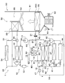
- FIG. 1 The refrigeration cycle apparatus 10 according to the first embodiment is applied to a vehicle air conditioner 1 for an electric vehicle that obtains a driving force for traveling a vehicle from a traveling electric motor.
- the refrigeration cycle apparatus 10 has a function of cooling or heating the blowing air blown into the vehicle compartment, which is a space to be air conditioned, in the vehicle air conditioner 1.
- the refrigeration cycle apparatus 10 is configured to be able to switch between a plurality of operation modes including a cooling mode for cooling the passenger compartment and a heating mode for heating the passenger compartment. .
- the blowing air blown into the vehicle compartment corresponds to the heat exchange target fluid of the present disclosure.
- the flow of the refrigerant in the heating mode is indicated by a solid arrow
- the flow of the refrigerant in the cooling mode is indicated by a broken arrow.
- an HFC refrigerant (specifically, R134a) is employed as the refrigerant, and a vapor compression subcritical refrigeration cycle in which the high-pressure refrigerant pressure does not exceed the critical pressure of the refrigerant is configured.
- an HFO-based refrigerant for example, R1234yf
- the refrigeration oil for lubricating the compressor 11 is mixed in the refrigerant, and a part of the refrigeration oil circulates in the cycle together with the refrigerant.
- the refrigeration cycle apparatus 10 includes a refrigeration cycle, a heating unit 30, and a heat medium circuit 40.
- the refrigeration cycle of the refrigeration cycle apparatus 10 includes a compressor 11, a refrigerant radiator 12, a liquid storage unit 13, an internal heat exchange unit 60, a first expansion valve 17, a cooling evaporation unit 20, and an evaporation pressure adjustment.
- the valve 21, the second expansion valve 23, and the heat absorption evaporator 70 are connected to each other.
- the compressor 11 is an electric compressor driven by electric power supplied from a battery, and sucks, compresses and discharges the refrigerant of the refrigeration cycle apparatus 10.
- the compressor 11 is configured as an electric compressor that drives, by an electric motor, a fixed displacement type compression mechanism whose discharge displacement is fixed, and is disposed in the casing of the vehicle air conditioner 1.
- this compression mechanism various compression mechanisms such as a scroll-type compression mechanism and a vane-type compression mechanism can be adopted.
- the operation (number of revolutions) of the electric motor constituting the compressor 11 is controlled by a control signal output from an air conditioning controller (not shown).
- an air conditioning controller not shown.
- any form of an alternating current motor and a direct current motor may be adopted.
- the refrigerant discharge capacity of the compressor 11 is changed by the air conditioning control device controlling the number of rotations of the electric motor.
- the compressor 11 may be a variable displacement compressor driven by a belt.
- the refrigerant inlet side of the refrigerant radiator 12 is connected to the outlet side of the compressor 11.
- the refrigerant radiator 12 constitutes a part of the heating unit 30 configured as a heat medium circuit, and is a high-temperature side heat medium that circulates the heating unit 30 as cooling water, and a high pressure refrigerant discharged from the compressor 11 And a heat exchanger for exchanging heat with each other.
- the refrigerant radiator 12 functions as a medium refrigerant heat exchanger in the present disclosure.
- the refrigerant radiator 12 dissipates the heat of the high pressure refrigerant discharged from the compressor 11 to the heat medium circulating through the heating unit 30.
- the configuration of heating unit 30 and the specific configuration of the heat medium in heating unit 30 will be described in detail later.
- a refrigerant inlet of the liquid storage section 13 is connected to the refrigerant outlet side of the refrigerant radiator 12.
- the liquid storage unit 13 is a receiver (i.e., a liquid receiver) that separates gas and liquid of the refrigerant flowing out of the refrigerant radiator 12 and stores excess liquid phase refrigerant.
- the refrigerant outlet (that is, the high pressure side refrigerant inlet 63 described later) of the high pressure side refrigerant passage 14 in the internal heat exchange unit 60 is connected to the refrigerant outlet of the liquid storage unit 13.
- the internal heat exchange unit 60 is a heat exchange unit that exchanges heat between the high pressure refrigerant flowing out of the refrigerant radiator 12 that constitutes a part of the heating unit 30 and the low pressure refrigerant drawn into the compressor 11.
- the internal heat exchange unit 60 is a heat exchange unit that exchanges heat between the high-pressure refrigerant flowing through the high-pressure refrigerant passage 14 and the low-pressure refrigerant flowing through the low-pressure refrigerant passage 26 described later.
- the configuration and the like of the internal heat exchange unit 60 will be described in detail later.
- a refrigerant branch unit 15 is disposed on the side of the refrigerant outlet (that is, the high pressure side refrigerant outlet 61 described later) of the high pressure side refrigerant flow passage 14 in the internal heat exchange unit 60.
- the refrigerant branch unit 15 is configured to have one refrigerant inlet and a plurality of refrigerant outlets, and the refrigerant flowing out from the high pressure side refrigerant flow path 14 of the internal heat exchange unit 60 is converted into a plurality of flows. Branch.
- coolant branch part 15 which concerns on 1st Embodiment has two refrigerant
- One of the refrigerant outlets in the refrigerant branch portion 15 is connected to the first parallel flow passage 16, and the other is connected to the second parallel flow passage 22. Therefore, the refrigerant branch unit 15 flows the refrigerant flow that has flowed out of the high pressure side refrigerant flow passage 14 of the internal heat exchange unit 60 through the first parallel flow passage 16 and the refrigerant that passes through the second parallel flow passage 22. Branch to the flow.
- the first expansion valve 17 has a valve body configured to be capable of changing the throttle opening, and an electric actuator that changes the opening degree of the valve, and is configured as an electric variable throttle mechanism. .
- the first expansion valve 17 exerts an throttling function to realize an arbitrary refrigerant pressure reducing action by setting the valve opening degree to an intermediate opening degree, and almost exhibits a flow rate adjusting action and a refrigerant pressure reducing action by fully opening the valve opening degree Instead, it has a fully open function that functions as a simple refrigerant passage, and a fully closed function that closes the refrigerant passage by fully closing the valve opening degree.
- the operation of the first expansion valve 17 is controlled by a control signal (i.e., control pulse) output from a control device (not shown).
- the first expansion valve 17 can reduce the pressure of the refrigerant flowing into the first parallel flow passage 16 until it becomes a low pressure refrigerant and allow the refrigerant to flow out.
- the first expansion valve 17 can adjust the flow rate of the refrigerant flowing to the first parallel flow passage 16 at the refrigerant branch portion 15, the flow rate of the refrigerant flowing to the second parallel flow passage 22 can be relatively adjusted. Can.
- the refrigerant inlet side of the cooling evaporation unit 20 is connected to the refrigerant outlet of the first expansion valve 17 via the first parallel flow passage 16.
- the cooling evaporation unit 20 is a heat exchanger disposed in an air conditioning case 51 of an indoor air conditioning unit 50 described later.
- the cooling evaporation unit 20 includes a cooling refrigerant flow path 200 for circulating the refrigerant.
- the cooling evaporation unit 20 cools the air passing through the inside of the air conditioning case 51 by evaporating the low-pressure refrigerant flowing through the cooling refrigerant flow path 200 to exhibit the heat absorption function.
- the cooling evaporation unit 20 is a heat exchange unit that absorbs and evaporates the heat of the blown air by the refrigerant.
- the inlet side of the evaporation pressure adjusting valve 21 is connected to the refrigerant outlet side of the cooling evaporation unit 20 via the first parallel flow path 16.
- the evaporation pressure control valve 21 is configured by a mechanical mechanism, and in order to suppress frost formation on the cooling evaporation unit 20, the refrigerant evaporation pressure in the cooling evaporation unit 20 is set to a reference pressure or more that can suppress frost formation. Perform the function of adjusting.
- the evaporation pressure control valve 21 functions to adjust the refrigerant evaporation temperature in the cooling evaporation unit 20 to a reference temperature or more that can suppress frost formation.
- a second parallel flow passage 22 is connected to the other of the refrigerant outlets in the refrigerant branch portion 15.
- a second expansion valve 23 and a heat absorption evaporation portion 70 are disposed in the second parallel flow passage 22.
- the second expansion valve 23 has a valve body configured to be capable of changing the throttle opening degree, and an electric actuator that changes the opening degree of the valve body. Is configured as a variable aperture mechanism of
- the second expansion valve 23 can exert the throttling function, the fully open function, and the fully closed function by appropriately adjusting the valve opening degree between the fully open state and the fully closed state. it can.
- the operation of the second expansion valve 23 is controlled by a control signal (i.e., control pulse) output from the controller.
- the second expansion valve 23 can reduce the pressure of the refrigerant flowing into the second parallel flow passage 22 until it becomes a low pressure refrigerant and allow the refrigerant to flow out.
- the second expansion valve 23 can adjust the flow rate of the refrigerant flowing to the second parallel flow passage 22 at the refrigerant branch portion 15, the flow rate of the refrigerant flowing to the first parallel flow passage 16 can be adjusted relatively Can.
- first expansion valve 17 and the second expansion valve 23 cooperate with each other to exhibit the function of adjusting the flow rate of the refrigerant passing through the first parallel flow passage 16 and the second parallel flow passage 22.
- first expansion valve 17 and the second expansion valve 23 exhibit a flow path switching function by causing either one to exhibit a fully closed function.
- the refrigerant inlet side of the heat absorption evaporation portion 70 is connected to the refrigerant outlet of the second expansion valve 23 via the second parallel flow path 22.
- the heat absorption evaporator 70 is a heat exchanger that constitutes a part of a heat medium circuit 40 described later.
- the heat-absorption evaporation unit 70 includes a heat-absorption refrigerant channel 24 through which the refrigerant flows.
- the heat absorption evaporation section 70 evaporates the low pressure refrigerant flowing through the heat absorption refrigerant flow path 24 to exhibit the heat absorption function, thereby to realize the heat of the low temperature side heat medium (that is, the cooling water) circulating in the heat medium circuit 40.
- Heat sink In other words, the heat absorption evaporation unit 70 is a heat exchange unit that absorbs and evaporates the heat of the low temperature side heat medium (that is, the cooling water) in the refrigerant.
- the configurations and the like of the heat medium circuit 40 and the heat absorption evaporation portion 70 will be described in detail later.
- the refrigerant merging portion 25 is configured to have a plurality of refrigerant inlets and one refrigerant outlet, and the flow of the plurality of refrigerants branched by the refrigerant branch portion 15 is one Join the
- the refrigerant merging portion 25 has two refrigerant inlets. One of the refrigerant inlets in the refrigerant merging portion 25 is connected to the refrigerant outlet side of the evaporation pressure adjusting valve 21, and the other is connected to the refrigerant outlet side of the heat absorption evaporator 70. Therefore, the refrigerant merging portion 25 merges the refrigerant flow that has passed through the first parallel flow passage 16 and the refrigerant flow that has passed through the second parallel flow passage 22 into one refrigerant flow and causes the refrigerant flow to flow out.
- the first parallel flow passage 16 and the second parallel flow passage are connected in parallel with each other.
- the cooling evaporator 20 and the heat absorption evaporator 70 are connected in parallel with each other.
- the cooling refrigerant flow channel 200 and the heat absorption refrigerant flow channel 24 are connected in parallel with each other.
- the refrigerant inlet side of the low-pressure refrigerant passage 26 in the internal heat exchange unit 60 is connected to the refrigerant outlet of the refrigerant merging unit 25.
- the suction port side of the compressor 11 is connected to the refrigerant outlet (that is, the low pressure side refrigerant outlet 64 described later) of the low pressure side refrigerant flow path 26 in the internal heat exchange unit 60.
- the heating unit 30 includes a refrigerant radiator 12 that constitutes a part of a refrigeration cycle, a heat medium circulation passage 31 as a heat medium flow path, a pressure feed pump 32, a heater core 33, and
- the high-temperature side heat medium circuit is configured to include the radiator 34 and the three-way valve 35.
- the heating unit 30 is configured by connecting the refrigerant radiator 12, the heater core 33, and the like by the heat medium circulation passage 31, and circulates the cooling water as the heat medium in the heat medium circulation passage 31 by the operation of the pressure pump 32. It is configured to let you
- the cooling water in the heating unit 30 is a high-temperature side heat medium, and for example, a liquid containing at least ethylene glycol, dimethylpolysiloxane or a nanofluid, or an antifreeze liquid is used.
- the pressure feed pump 32 is a heat medium pump that sucks in and discharges cooling water as a high temperature side heat medium, and is configured by an electric pump.
- the pressure feed pump 32 circulates the cooling water in the heat medium circulation passage 31 of the heating unit 30 by pressure-feeding the cooling water in the heat medium circulation passage 31.
- the operation of the pumping pump 32 is controlled by a control signal output from the controller. That is, the pressure feed pump 32 can adjust the flow rate of the cooling water circulating through the heating unit 30 by the control of the control device, and functions as a heat medium flow rate adjusting unit in the heating unit 30.
- a refrigerant radiator 12 is connected to the discharge port side of the pressure feed pump 32. Therefore, the refrigerant radiator 12 can dissipate the heat of the high-pressure refrigerant to the cooling water by heat exchange between the high-pressure refrigerant passing therethrough and the cooling water circulating through the heat medium circulation passage 31.
- a three-way valve 35 is connected to the coolant outlet side of the refrigerant radiator 12.
- the three-way valve 35 has two outlets, and can switch the flow of cooling water flowing from one inlet to either outlet side.
- a heater core 33 is connected to one outlet of the three-way valve 35, and a first radiator 34 is connected to the other outlet. Therefore, the three-way valve 35 can switch the flow of the cooling water having passed through the refrigerant radiator 12 to either the heater core 33 side or the first radiator 34 side.
- the three-way valve 35 functions as a heat medium flow path switching unit in the heating unit 30.
- the heater core 33 is disposed downstream of the cooling evaporation portion 20 in the air conditioning case 51 of the indoor air conditioning unit 50 in the flow direction of the blowing air.
- the heater core 33 is a high-temperature side heat medium heat exchanger that heats the air by heat exchange between the cooling water circulating through the heat medium circulation passage 31 of the heating unit 30 and the air blown into the vehicle compartment.
- the heater core 33 indirectly exchanges heat between the refrigerant discharged from the compressor 11 and the blown air via the cooling water circulating through the heat medium circulation passage 31, and the refrigerant discharged from the compressor 11 It is a heat exchanger for heating which heats blast air by the heat which it has.
- the cooling water dissipates heat to the blown air blown into the vehicle compartment by the sensible heat change.
- the refrigeration cycle apparatus 10 can heat the vehicle interior.
- the cooling water does not undergo a phase change in the liquid phase.
- the first radiator 34 is a heat exchanger for radiating heat that radiates the heat of the cooling water to the outside air by exchanging heat between the cooling water circulating through the heat medium circulation passage 31 of the heating unit 30 and the outside air of the electric vehicle. is there.
- the first radiator 34 is connected in parallel to the heater core 33 in the heat medium circulation passage 31 of the heating unit 30. And since the heat which cooling water has is radiated to the open air from the 1st radiator 34, refrigerating cycle device 10 does not warm blowing air, but can exhaust heat to the car exterior.
- the heating part 30 of the refrigerating-cycle apparatus 10 can switch the flow of a cooling water with the three-way valve 35, and can change the utilization aspect of the heat which a high voltage
- the heat medium circuit 40 includes a heat absorption evaporation portion 70 which forms a part of a refrigeration cycle, a heat medium circulation passage 41 as a heat medium flow passage, a pressure feed pump 42, and a second radiator 43. And the on-vehicle device 44, the first on-off valve 45, and the second on-off valve 46.
- the heat medium circuit 40 is configured by connecting the heat absorption / evaporation unit 70, the second radiator 43, and the like by the heat medium circulation passage 41, and the pressure pump 42 sends cooling water as the heat medium in the heat medium circulation passage 41. It is configured to circulate by the operation of
- the cooling water in the heat medium circuit 40 is a low temperature heat medium, and for example, a liquid containing at least ethylene glycol, dimethylpolysiloxane or nanofluid, or an antifreeze liquid is used.
- the pressure feed pump 42 is a heat medium pump that sucks and discharges cooling water as a heat medium, and is configured by an electric pump.
- the pressure feed pump 42 circulates the cooling water in the heat medium circulation passage 41 of the heat medium circuit 40 by pressure-feeding the cooling water in the heat medium circulation passage 41.
- the operation of the pumping pump 42 is controlled by a control signal output from the control device. That is, the pressure feed pump 42 can adjust the flow rate of the cooling water circulating in the heat medium circuit 40 by the control of the control device, and functions as a heat medium flow rate adjustment unit in the heat medium circuit 40.
- the heat absorption evaporator 70 includes a cooling water flow path 47 for circulating cooling water as a heat medium.
- the discharge port side of the pressure-feed pump 42 is connected to the cooling water inlet (that is, a cooling water inlet 72 described later) of the cooling water flow path 47 in the heat absorption evaporation section 70. Therefore, the heat absorbing evaporation section 70 can cause the low pressure refrigerant to absorb the heat of the cooling water by heat exchange between the low pressure refrigerant flowing through the heat absorbing refrigerant flow channel 24 and the cooling water flowing through the cooling water flow channel 47. it can.
- the heat medium passage having the second radiator 43 and the heat medium passage having the on-vehicle device 44 are connected to the cooling water outlet (that is, the cooling water outlet 73 described later) in the heat absorption evaporator 70. It is done. That is, in the heat medium circuit 40 according to the first embodiment, the second radiator 43 and the first on-off valve 45, and the on-vehicle device 44 and the second on-off valve 46 are connected in parallel.
- the second radiator 43 absorbs heat of the outside air by heat exchange between the cooling water circulating through the heat medium circulating passage 41 of the heat medium circuit 40 and the outside air of the electric vehicle, thereby absorbing heat of the outside air. It is. That is, when circulating the cooling water through the second radiator 43, the heat medium circuit 40 uses the outside air outside the electric vehicle as the external heat source.
- a first on-off valve 45 is disposed on the cooling water flow upstream side of the cooling water inlet in the second radiator 43.
- the first on-off valve 45 is configured to be adjustable in opening degree between the fully closed state and the fully open state of the cooling water passage directed to the cooling water inlet of the second radiator 43.
- the operation of the first on-off valve 45 is controlled by a control signal output from the control device.
- the heat medium circuit 40 can switch the presence or absence of the cooling water flow to the second radiator 43 by controlling the opening degree of the first on-off valve 45 by the control device.
- the refrigeration cycle apparatus 10 can switch whether to use the outside air as an external heat source.
- the in-vehicle device 44 is mounted on the electric vehicle and is constituted by a device that generates heat as it operates.
- the on-vehicle device 44 includes a charger for charging the battery of the electric vehicle, a motor generator, an inverter, etc. .
- the on-vehicle device 44 functions as a heat generating device in the present disclosure.
- the heat medium circulation passage 41 in the heat medium circuit 40 is disposed to be in contact with the outer surface of the on-vehicle devices 44, and the heat of the on-vehicle devices 44 can be exchanged with the cooling water flowing through the heat medium passage. Is configured.
- a second on-off valve 46 is disposed on the cooling water flow upstream side of the cooling water inlet in the in-vehicle device 44.
- the second on-off valve 46 is configured to be able to adjust the opening degree between the fully closed state and the fully open state of the cooling water passage toward the cooling water inlet of the in-vehicle device 44.
- the operation of the second on-off valve 46 is controlled by a control signal output from the control device.
- the heat medium circuit 40 can switch the presence or absence of the cooling water flow with respect to the vehicle-mounted apparatus 44 by opening degree control of the 2nd on-off valve 46 by a control apparatus.
- the refrigeration cycle apparatus 10 can switch whether to use the on-vehicle device 44 as an external heat source.
- the indoor air conditioning unit 50 which comprises the vehicle air conditioner 1 is demonstrated, referring FIG.
- the indoor air conditioning unit 50 constitutes a part of the vehicle air conditioner 1, and blows out the blowing air whose temperature has been adjusted by the refrigeration cycle apparatus 10 into the vehicle compartment.
- the indoor air conditioning unit 50 is disposed inside the instrument panel (i.e., instrument panel) at the front of the passenger compartment of the electric vehicle.
- the indoor air conditioning unit 50 accommodates the blower 52, the heat absorption evaporator 70, the heater core 33, and the like in an air passage formed in the air conditioning case 51 forming the outer shell thereof.
- the air conditioning case 51 forms an air passage of the blowing air blown into the vehicle compartment, and is molded of a resin (for example, polypropylene) having a certain degree of elasticity and excellent in strength.
- a resin for example, polypropylene
- An internal / external air switching device 53 is disposed on the most upstream side of the air flow of the air conditioning case 51.
- the inside / outside air switching device 53 switches and introduces inside air (i.e., vehicle interior air) and outside air (i.e., air outside the vehicle interior) into the air conditioning case 51.
- the inside / outside air switching device 53 continuously adjusts the opening area of the inside air introduction port for introducing inside air into the air conditioning case 51 and the outside air introduction port for introducing outside air by means of the inside / outside air switching door. Change the introduction ratio of the introduction air volume of and the introduction air volume of the outside air.
- the inside / outside air switching door is driven by an electric actuator for the inside / outside air switching door, and the operation of the electric actuator is controlled by a control signal output from the control device.
- a blower 52 is disposed downstream of the inside / outside air switching device 53 in the flow of the blown air.
- the blower 52 is an electric blower that drives a centrifugal multi-blade fan by an electric motor, and blows the drawn air toward the vehicle interior via the inside / outside air switching device 53.
- the rotation speed (i.e., the blowing capacity) of the blower 52 is controlled by the control voltage output from the control device.
- a cooling evaporation unit 20 and a heater core 33 are disposed in this order on the downstream side of the air flow of the fan 52 with respect to the air flow. That is, the cooling evaporator 20 is disposed upstream of the heater core 33 in the flow of the blowing air.
- a bypass passage 55 is provided in the air conditioning case 51.
- the bypass passage 55 is configured to flow the blown air after passing through the cooling evaporation unit 20 by bypassing the heater core 33.
- An air mix door 54 is disposed downstream of the air flow of the cooling evaporation unit 20 in the air conditioning case 51 and upstream of the air flow of the heater core 33.
- the air mix door 54 adjusts the air volume ratio to adjust the air volume ratio of the air volume of the air passing through the heater core 33 and the air volume of the air passing through the bypass passage 55 among the air after passing through the cooling evaporation section 20 It is a department.
- the air mix door 54 is driven by an electric actuator for the air mix door.
- the operation of the electric actuator is controlled by a control signal output from the controller.
- a merging space 56 is formed downstream of the heater core 33 and the bypass passage 55 in the air flow direction.
- the merging space 56 is formed so that the blowing air heated by heat exchange with the heat medium (that is, the cooling water) by the heater core 33 and the blowing air not passing through the bypass passage 55 merge. ing. Therefore, by adjusting the air volume ratio of the air mix door 54, the temperature of the blowing air merged in the merging space 56 is adjusted.
- the door for adjusting each opening area is arrange
- the defroster door, the face door, and the foot door are arranged to correspond to the defroster hole, the face hole, and the foot hole, respectively.
- the operation of each door is controlled by a control signal of the control device, and the doors constitute a blowout mode switching device that switches the blowout mode by opening and closing the respective opening holes.
- the control device is composed of a known microcomputer including a CPU, a ROM, a RAM and the like, and peripheral circuits thereof. Then, the control device performs various calculations and processing based on the air conditioning control program stored in the ROM, and controls the operation of various air conditioning control devices connected to the output side.
- a plurality of types of air conditioning control devices and electric actuators are connected to the output side of the control device.
- a plurality of types of air conditioning control devices and the like include the compressor 11, the first expansion valve 17, the second expansion valve 23, the blower 52, the inside / outside air switching device 53, the air mix door 54, and the pressure pump 32;
- a three-way valve 35, a pressure feed pump 42, a first on-off valve 45, and a second on-off valve 46 are included.
- An operation panel (not shown) used for various input operations is connected to the input side of the control device.
- the operation panel is disposed in the vicinity of the dashboard in the front of the passenger compartment and has various operation switches. Therefore, operation signals from various operation switches provided on the operation panel are input to the control device.
- the various operation switches of the operation panel include an auto switch, an operation mode switch, an air volume setting switch, a temperature setting switch, a blowout mode switch, and the like. Therefore, the refrigeration cycle apparatus 10 can appropriately switch the operation mode of the refrigeration cycle apparatus 10 by receiving an input from the operation panel.
- the air conditioning control sensor group includes an inside air temperature sensor, an outside air temperature sensor, a solar radiation sensor, and the like.
- the inside air temperature sensor is an inside air temperature detection unit that detects the temperature inside the vehicle (that is, the inside air temperature).
- the outside air temperature sensor is an outside air temperature detector that detects the temperature outside the vehicle (that is, the outside air temperature).
- the solar radiation sensor is a solar radiation amount detection unit that detects the amount of solar radiation emitted into the vehicle compartment.
- the refrigeration cycle apparatus 10 can adjust the temperature etc. of the blowing air blown into the vehicle compartment according to the physical quantity detected by the sensor group for air conditioning control, and realize comfortable air conditioning. it can.
- the vehicle air conditioner 1 can execute a cooling mode and a heating mode as an operation mode.
- the cooling mode is an operation mode for cooling the air, which is a heat exchange target fluid, to cool the vehicle interior.
- the heating mode is an operation mode in which heat is absorbed from the outside air as an external heat source, and the blown air which is a fluid to be heat-exchanged is heated to heat the vehicle interior.
- the throttle opening degree of the first expansion valve 17 is determined to be a predetermined opening degree for the cooling mode set in advance.
- the throttle opening degree of the second expansion valve 23 is determined to be fully closed.
- the refrigerant circuit is switched to the refrigerant circuit indicated by the dashed arrow in FIG.
- the air mix door 54 closes the upstream side of the air flow of the heater core 33, and the total flow rate of the air after passing through the cooling evaporator 20 is the bypass passage 55 It is decided to pass through.
- the control signals for the compressor 11, the blower 52, and the inside / outside air switching device 53 are appropriately determined using the input operation of the operation panel or the detection signal of the sensor group.
- the high pressure refrigerant discharged from the compressor 11 flows into the refrigerant radiator 12.
- the refrigerant flowing into the refrigerant radiator 12 dissipates heat to the cooling water flowing through the heat medium circulation passage 31 of the heating unit 30. Therefore, the cooling water in the heating unit 30 is heated by the heat of the high pressure refrigerant, and the refrigerant radiator 12 functions as a radiator.
- the refrigerant that has flowed out of the refrigerant radiator 12 flows into the high pressure side refrigerant flow path 14 of the internal heat exchange unit 60 via the liquid storage unit 13.
- the high pressure refrigerant flowing into the high pressure side refrigerant flow passage 14 of the internal heat exchange unit 60 exchanges heat with the low pressure refrigerant flowing through the low pressure side refrigerant flow passage 26 of the internal heat exchange unit 60 and reaches the refrigerant branch unit 15.
- the first expansion valve 17 is in the squeezed state and the second expansion valve 23 is in the fully closed state. For this reason, the refrigerant flowing out of the refrigerant branch portion 15 flows into the first parallel flow passage 16 and is decompressed isoenthaltically until the first expansion valve 17 becomes a low pressure refrigerant.
- the low-pressure refrigerant flowing out of the first expansion valve 17 flows into the cooling evaporation unit 20 disposed in the air conditioning case 51, exchanges heat with the air blown by the blower 52, and absorbs heat.
- the air blown by the blower 52 is cooled and blown into the vehicle compartment via the bypass passage 55.
- the refrigerant that has flowed out of the cooling evaporation unit 20 flows into the low pressure side refrigerant flow passage 26 of the internal heat exchange unit 60 via the evaporation pressure adjustment valve 21 and the refrigerant merging unit 25.
- the low pressure refrigerant flowing into the low pressure side refrigerant flow passage 26 of the internal heat exchange unit 60 exchanges heat with the high pressure refrigerant flowing through the high pressure side refrigerant flow passage 14 of the internal heat exchange unit 60, and is sucked into the compressor 11 and compressed again. Be done.
- the control signal of the three-way valve 35 in the cooling mode is determined so that the entire amount of the cooling water flowing out of the refrigerant radiator 12 flows into the first radiator 34.
- the heat of the high-pressure refrigerant is radiated to the cooling water of the heating unit 30. Accordingly, the cooling water flowing out of the refrigerant radiator 12 passes through the three-way valve 35 in the high temperature state and flows into the first radiator 34.
- the cooling water having flowed into the first radiator 34 is dissipated through the first radiator 34 to the outside air outside the electric vehicle. That is, according to the refrigeration cycle apparatus 10, the heat of the high-pressure refrigerant is dissipated to the outside air through the cooling water of the heating unit 30.
- the cooling water radiated by the first radiator 34 is circulated according to the operation of the pressure feed pump 32, and is again sucked into the pressure feed pump 32 and pressure fed to the refrigerant radiator 12.
- the low-pressure refrigerant in the refrigeration cycle apparatus 10 does not pass through the heat absorption evaporation portion 70. Therefore, the operating state of the heat medium circuit 40 thermally connected to the heat absorption evaporator 70 can be arbitrarily determined.
- the heat of the high-pressure refrigerant is dissipated to the outside air through the cooling water of the heating unit 30, and the low-pressure refrigerant absorbs heat from the blown air blown into the vehicle compartment by the cooling evaporation unit 20 Can be cooled. Thereby, cooling of the vehicle interior can be realized.
- the internal heat exchange unit 60 exchanges heat between the high pressure refrigerant flowing out of the refrigerant radiator 12 and the low pressure refrigerant flowing out of the cooling evaporation unit 20, thereby reducing the heat of the high pressure refrigerant to the low pressure refrigerant.
- the low pressure refrigerant is cooled by absorbing heat. For this reason, since the enthalpy of the inlet side refrigerant of the cooling evaporation unit 20 is lowered, the enthalpy difference (in other words, the refrigeration capacity) between the outlet side refrigerant and the inlet side refrigerant of the cooling evaporation unit 20 is increased, The coefficient of performance (so-called COP) can be improved.
- the throttle opening degree of the second expansion valve 23 is determined to be a predetermined opening degree for the heating mode set in advance.
- the throttle opening degree of the first expansion valve 17 is determined to be fully closed. Thereby, the refrigerant circuit is switched to the refrigerant circuit indicated by the solid line arrow in FIG.
- the air mix door 54 closes the bypass passage 55 so that the total flow rate of the blown air after passing through the cooling evaporation section 20 passes through the heater core 33.
- the control signals for the compressor 11, the blower 52, and the inside / outside air switching device 53 are appropriately determined using the input operation of the operation panel or the detection signal of the sensor group.
- the high pressure refrigerant discharged from the compressor 11 flows into the refrigerant radiator 12.
- the refrigerant flowing into the refrigerant radiator 12 dissipates heat to the cooling water flowing through the heat medium circulation passage 31 of the heating unit 30. Therefore, the cooling water in the heating unit 30 is heated by the heat of the high pressure refrigerant, and the refrigerant radiator 12 functions as a radiator.
- the refrigerant flowing out of the refrigerant radiator 12 flows into the high pressure side refrigerant flow passage 14 of the internal heat exchange unit 60 via the liquid storage unit 13.
- the high pressure refrigerant flowing into the high pressure side refrigerant flow passage 14 of the internal heat exchange unit 60 exchanges heat with the low pressure refrigerant flowing through the low pressure side refrigerant flow passage 26 of the internal heat exchange unit 60 and reaches the refrigerant branch unit 15.
- the second expansion valve 23 is in the squeezed state and the first expansion valve 17 is in the fully closed state. For this reason, the refrigerant flowing out of the refrigerant branch portion 15 flows into the second parallel flow passage 22 and is decompressed isoenthalpically until it becomes a low pressure refrigerant by the second expansion valve 23.
- the low-pressure refrigerant flowing out of the second expansion valve 23 flows into the heat absorption evaporation section 70 and exchanges heat with the cooling water circulating through the heat medium circuit 40. That is, in the heat absorption evaporation section 70, the low pressure refrigerant absorbs heat and is heated by the cooling water of the heat medium circuit 40, and the cooling water of the heat medium circuit 40 is cooled by heat exchange with the low pressure refrigerant.
- the refrigerant flowing out of the heat absorption evaporation unit 70 flows into the low pressure side refrigerant flow passage 26 of the internal heat exchange unit 60 via the refrigerant merging unit 25.
- the low pressure refrigerant flowing into the low pressure side refrigerant flow passage 26 of the internal heat exchange unit 60 exchanges heat with the high pressure refrigerant flowing through the high pressure side refrigerant flow passage 14 of the internal heat exchange unit 60, and is sucked into the compressor 11 and compressed again. Be done.
- the control signal of the three-way valve 35 in the heating mode is determined so that the entire amount of the cooling water flowing out of the refrigerant radiator 12 flows into the heater core 33.
- the heat of the high-pressure refrigerant is radiated to the cooling water of the heating unit 30. Accordingly, the cooling water flowing out of the refrigerant radiator 12 passes through the three-way valve 35 in the high temperature state and flows into the heater core 33.
- the coolant flowing into the heater core 33 exchanges heat with the air blown by the blower 52 in the heater core 33.
- the blown air reaches the heater core 33 without being cooled by the cooling evaporator 20.
- the heat of the high-pressure refrigerant is dissipated to the blowing air blown into the vehicle compartment via the cooling water of the heating unit 30.
- the blown air warmed by the heat of the high-pressure refrigerant can be supplied into the passenger compartment, and the passenger compartment can be heated.
- the cooling water dissipated by the heater core 33 is circulated along with the operation of the pressure feed pump 32, and is again sucked into the pressure feed pump 32 and pressure fed to the refrigerant radiator 12.
- the control signals of the first on-off valve 45 and the second on-off valve 46 in the heating mode are determined, for example, to fully open the first on-off valve 45 and fully close the second on-off valve 46.
- the cooling water absorbs heat from the outside air at the second radiator 43. That is, the refrigeration cycle apparatus 10 in this case utilizes outside air as an external heat source.
- the cooling water which has flowed out of the second radiator 43 by the operation of the pressure pump 42 flows into the heat absorption evaporator 70 via the pressure pump 42.
- heat absorption evaporator 70 heat exchange is performed between the low pressure refrigerant and the cooling water of the heat medium circuit 40. For this reason, the heat of the cooling water in the heat medium circuit 40 is absorbed by the low pressure refrigerant.
- the refrigeration cycle apparatus 10 can use outside air as an external heat source in the heating mode.
- the cooling water passes through the second radiator 43 because the first on-off valve 45 is fully opened and the second on-off valve 46 is fully closed. That is, it was an aspect using outside air as an external heat source in heating mode. However, depending on the opening and closing control of the first on-off valve 45 and the second on-off valve 46, various modes can be adopted as the utilization mode of the external heat source.
- the refrigeration cycle apparatus 10 can use the on-vehicle device 44 as an external heat source in the heating mode.
- the refrigeration cycle apparatus 10 can use the outside air and the in-vehicle device 44 in combination as an external heat source in the heating mode.
- the heat of the external heat source that is, the outside air or the on-vehicle device 44
- the low pressure refrigerant via the cooling water of the heat medium circuit 40, and via the cooling water of the heating unit 30.
- the heat of the high-pressure refrigerant can be dissipated and heated to the air blown into the vehicle compartment. Thereby, heating of the vehicle interior can be realized.
- the internal heat exchange unit 60 exchanges heat between the high pressure refrigerant flowing out of the refrigerant radiator 12 and the low pressure refrigerant flowing out of the heat absorption evaporator 70, thereby reducing the heat of the high pressure refrigerant to the low pressure refrigerant.
- the low pressure refrigerant is cooled by absorbing heat.
- the enthalpy of the inlet-side refrigerant of the endothermic evaporator 70 decreases, so the enthalpy difference (in other words, the refrigeration capacity) between the outlet-side refrigerant and the inlet-side refrigerant of the endothermic evaporator 70 is increased,
- the coefficient of performance (so-called COP) can be improved.
- FIG. 2 the flow of the high pressure refrigerant is indicated by a solid arrow, the flow of the low pressure refrigerant is indicated by a broken arrow, and the flow of the cooling water is indicated by a dashed dotted arrow.
- the refrigeration cycle apparatus 10 includes a combined heat exchanger 80 in which a heat absorption evaporation portion 70 and an internal heat exchange portion 60 are integrally formed.
- the refrigeration cycle apparatus 10 includes the combined heat exchanger 80 having the heat absorption evaporation portion 70 and the internal heat exchange portion 60.
- the combined heat exchanger 80 includes a heat exchange portion 800 formed by laminating and joining a plurality of plate members 81 to each other.
- the heat exchange unit 800 has a heat absorption evaporation unit 70 and an internal heat exchange unit 60. That is, a part of the heat exchange part 800 constitutes the heat absorption evaporation part 70, and the remaining part of the heat exchange part 800 constitutes the internal heat exchange part 60.
- the longitudinal direction (vertical direction in the example of FIG. 2) of the plurality of plate members 81 is referred to as the plate longitudinal direction, and the lamination direction of the plurality of plate members 81 (horizontal direction in the example of FIG. .
- One side in the plate stacking direction, that is, one end side in the plate stacking direction (left end side in the example of FIG. 2) is referred to as one plate stacking direction end side.
- the other side of the plate stacking direction, that is, the other end side (right end side in the example of FIG. 2) of the plate stacking direction is referred to as the other side in the plate stacking direction.
- the plate stacking direction is a direction orthogonal to the plate surface of the plate-like member 81.
- the heat absorbing evaporator 70 and the internal heat exchange unit 60 are arranged in a direction perpendicular to the plate stacking direction. Specifically, the heat absorbing evaporator 70 and the internal heat exchange unit 60 are arranged side by side in the plate longitudinal direction.
- the size of the endothermic evaporation portion 70 and the size of the internal heat exchange portion 60 are different. Specifically, the length in the plate longitudinal direction of the heat absorption evaporating portion 70 is longer than the length in the plate longitudinal direction of the internal heat exchange portion 60.
- the plate-like member 81 is an elongated rectangular (i.e., rectangular) plate material.
- a specific material of the plate-like member 81 for example, a double-sided clad material in which a brazing material is clad on both sides of an aluminum core material is used.
- an overhanging portion 811 that protrudes in the plate stacking direction is formed at the outer peripheral edge of the plate-like member 81.
- the plurality of plate members 81 are joined to each other by brazing in a state in which the plurality of plate members 81 are stacked.
- a plurality of heat absorption refrigerant flow paths 24 for flowing the refrigerant and a plurality of cooling water flow paths 47 for flowing the cooling water are formed.
- Each of the heat absorption coolant channel 24 and the cooling water channel 47 is formed between the plurality of plate members 81.
- the longitudinal directions of the heat absorption coolant channel 24 and the cooling water channel 47 coincide with the longitudinal direction of the plate-like member 81.
- the heat absorption refrigerant flow path 24 and the cooling water flow path 47 are alternately stacked one by one in the plate stacking direction (that is, arranged in parallel).
- the plate-like member 81 plays the role of a partition that separates the heat absorption coolant channel 24 and the cooling water channel 47. Heat exchange between the refrigerant flowing through the heat absorption refrigerant flow passage 24 and the cooling water flowing through the cooling water flow passage 47 is performed via the plate-like member 81.
- the heat absorption evaporation section 70 is configured such that the flow of the refrigerant flowing through the heat absorption refrigerant flow channel 24 and the flow of the cooling water flowing through the cooling water flow channel 47 are in opposite directions (so-called countercurrent flow). .
- the internal heat exchange unit 60 is formed with a plurality of high pressure side refrigerant flow paths 14 for circulating the refrigerant flowing out from the refrigerant radiator 12 and a plurality of low pressure side refrigerant flow paths 26 for circulating the refrigerant drawn into the compressor 11. ing.
- the high pressure side refrigerant flow passage 14 and the low pressure side refrigerant flow passage 26 are respectively formed between the plurality of plate members 81.
- the longitudinal directions of the high pressure side refrigerant flow passage 14 and the low pressure side refrigerant flow passage 26 coincide with the longitudinal direction of the plate-like member 81.
- the high-pressure side refrigerant flow path 14 and the low-pressure side refrigerant flow path 26 are alternately stacked one by one in the plate stacking direction (that is, arranged in parallel).
- the plate member 81 plays the role of a partition that divides the high pressure side refrigerant flow passage 14 and the low pressure side refrigerant flow passage 26. Heat exchange between the refrigerant flowing through the high pressure side refrigerant flow passage 14 and the refrigerant flowing through the low pressure side refrigerant flow passage 26 is performed via the plate-like member 81.
- the internal heat exchange unit 60 is configured such that the flow of refrigerant flowing through the low pressure side refrigerant flow channel 26 and the flow of refrigerant flowing through the high pressure side refrigerant flow channel 14 are in opposite directions (so-called countercurrent flow). There is.
- the heat exchange unit 800 includes a heat absorption refrigerant tank 82 (see FIG. 3), a cooling water tank, a high pressure side refrigerant tank, and a low pressure side refrigerant tank.
- the cooling water tank, the high pressure side refrigerant tank, and the low pressure side refrigerant tank are not shown.
- the heat absorption refrigerant tank 82 distributes or collects the refrigerant to the plurality of heat absorption refrigerant channels 24.
- the cooling water tank distributes or collects cooling water to the plurality of cooling water flow paths 47.
- the high pressure side refrigerant tank distributes or collects the refrigerant to the plurality of high pressure side refrigerant channels 14.
- the low pressure side refrigerant tank distributes or collects the refrigerant to the plurality of low pressure side refrigerant channels 26.
- the plate-like member 81 has a plurality of substantially cylindrical protrusions 83 projecting toward one end side or the other end side in the plate stacking direction.
- the inner surface of the projecting portion 83 of one plate member 81 and the outer surface of the projecting portion 83 of the other plate member 81 are joined.
- the heat absorption refrigerant tank 82, the cooling water tank, the high pressure side refrigerant tank, and the low pressure side refrigerant tank are respectively formed by the projecting portion 83 joined in this manner.
- the heat absorption evaporation portion 70 and the internal heat exchange portion 60 are arranged side by side in the plate longitudinal direction. For this reason, the heat absorption refrigerant flow channel 24 or the cooling water flow channel 47 and the high pressure side refrigerant flow channel 14 or the low pressure side refrigerant flow channel 26 are provided between the plurality of plate members 81.
- Inner fins 84 are disposed between the plate-like members 81.
- the inner fins 84 are interposed between the plate members 81, and promote heat exchange between the heat absorbing refrigerant and the cooling water, and between the low pressure side refrigerant and the high pressure side refrigerant.
- an offset fin can be employed as the inner fin 84.
- the combined heat exchanger 80 has a high pressure side refrigerant outlet 61, a low pressure side refrigerant inlet 62, a high pressure side refrigerant inlet 63, a low pressure side refrigerant outlet 64, a heat absorbing refrigerant inlet 71, A cooling water inlet 72 and a cooling water outlet 73 are provided.
- the high pressure side refrigerant outlet 61 causes the refrigerant flowing out of the high pressure side refrigerant flow passage 14 of the internal heat exchange unit 60 to flow out to the cooling refrigerant flow passage 200 of the cooling evaporation unit 20.
- the low pressure side refrigerant introduction port 62 causes the refrigerant flowing out of the cooling refrigerant flow passage 200 of the cooling evaporation unit 20 to flow into the low pressure side refrigerant flow passage 26 of the internal heat exchange unit 60.
- the high pressure side refrigerant introduction port 63 causes the refrigerant flowing out of the refrigerant radiator 12 to flow into the high pressure side refrigerant flow passage 14 of the internal heat exchange unit 60.
- the low pressure side refrigerant outlet 64 causes the refrigerant flowing out of the low pressure side refrigerant flow passage 26 of the internal heat exchange unit 60 to flow out to the suction side of the compressor 11.
- the heat absorbing refrigerant inlet 71 causes the refrigerant flowing out of the high pressure side refrigerant flow passage 14 of the internal heat exchange unit 60 to flow into the heat absorbing refrigerant flow passage 24 of the heat absorption evaporating unit 70 in the heating mode.
- the cooling water inlet 72 causes the cooling water discharged from the pressure pump 42 to flow into the cooling water flow path 47 of the heat absorption evaporator 70.
- the cooling water outlet port 73 causes the refrigerant flowing out of the cooling water flow path 47 of the heat absorption evaporating portion 70 to flow out to the second radiator 43 side or the on-vehicle equipment 44 side in the heat medium circulation passage 41.
- the plate-like members 81 forming the outermost side in the plate stacking direction of the heat exchange portion are referred to as outer plate-like members 81A and 11B.
- the outer plate members 81A and 11B one disposed at one end side in the plate stacking direction is referred to as a first outer plate member 81A, and one disposed at the other end side in the plate stacking direction is a second outer plate shape. It is called member 81B.
- the high pressure side refrigerant outlet port 61, the low pressure side refrigerant inlet port 62, the heat absorption refrigerant inlet port 71, and the cooling water outlet port 73 are disposed on the plate surface of the first outer plate member 81A.
- the high pressure side refrigerant inlet port 63, the low pressure refrigerant outlet port, and the cooling water inlet port 72 are disposed on the plate surface of the second outer plate member 81.
- the connecting refrigerant channel 85 is formed to connect the low-pressure side refrigerant channel 26 in the replacement section 60 with the most upstream portion.
- the low pressure side refrigerant introduction port 62 is disposed in communication with the connection refrigerant flow path 85.
- connection refrigerant flow path 85 the refrigerant flow flowing from the low pressure side refrigerant introduction port 62 (that is, the refrigerant flowing out of the cooling refrigerant flow path 200 of the cooling evaporation unit 20) and the heat absorption refrigerant flow path 24
- the refrigerant flow that has flowed out is merged into one refrigerant flow. That is, in the composite heat exchanger 80, the refrigerant flow that has flowed out of the cooling refrigerant flow path 200 of the cooling evaporation unit 20 and the refrigerant flow that has flowed out of the heat absorption refrigerant flow path 24 merge into one refrigerant flow. Be done.
- the refrigerant merging portion 25 of the refrigeration cycle apparatus 10 is disposed inside the combined heat exchanger 80.
- the low-pressure refrigerant flowing out of the heating unit 30 and the compressor 11 are sucked into the refrigeration cycle apparatus 10 (more specifically, the heat exchange unit 800 of the combined heat exchanger 80).
- An internal heat exchange unit 60 is provided to exchange heat with the high pressure refrigerant.
- the combined heat exchanger 80 of the present embodiment has the heat exchange unit 800 in which the heat absorption evaporation unit 70 and the internal heat exchange unit 60 are integrated, and the high pressure side refrigerant outlet 61 and A low pressure side refrigerant inlet 62 is provided. For this reason, even in the refrigeration cycle apparatus 10 including the internal heat exchange unit 60, the cycle configuration can be simplified.
- the endothermic evaporation unit 70 and the internal heat exchange unit 60 are common in the point of a heat exchanger in which no air is present. For this reason, as in the present embodiment, a laminated heat exchanger formed by laminating the plurality of plate members 81 and joining them together as well as the heat absorbing evaporation portion 70 and the internal heat exchange portion 60 The heat absorption evaporator 70 and the internal heat exchange unit 60 can be integrated.
- the low pressure side refrigerant which causes the refrigerant flowing out of the cooling refrigerant flow passage 200 of the cooling evaporation unit 20 to the low pressure side refrigerant flow passage 26 of the internal heat exchange unit 60 in the composite heat exchanger 80.
- An introduction port 62 is provided. According to this, it is possible to cause both the refrigerant branched to the heat absorption evaporation portion 70 side and the cooling evaporation portion 20 side in the refrigerant branch portion 15 to flow into the low pressure side refrigerant flow path 26 of the internal heat exchange portion 60. Therefore, even if the operation mode of the refrigeration cycle apparatus 10 is either the cooling mode or the heating mode, the coefficient of performance of the refrigeration cycle apparatus 10 can be improved.
- the high-pressure refrigerant outlet 61, the low-pressure refrigerant inlet 62, the high-pressure refrigerant inlet 63, and the low-pressure refrigerant outlet 64 form the outer side of the heat exchange section 800 in the plate stacking direction. It arrange
- the size of the heat absorption evaporation portion 70 and the size of the internal heat exchange portion 60 are made different. At this time, according to this, it is possible to optimize the sizes of the endothermic heat evaporation portion 70 and the internal heat exchange portion 60 in the entire heat exchange portion 800.
- the heat absorption evaporation portion 70 and the internal heat exchange portion 60 are arranged in a direction perpendicular to the plate stacking direction. According to this, it is possible to form the most downstream part of the heat absorption refrigerant flow path 24, the connection refrigerant flow path 85, and the uppermost flow area of the low pressure side refrigerant flow path 26 by the same plate member 81. For this reason, it is possible to reduce the pressure loss when the refrigerant passes through the connecting refrigerant channel 85.
- the low pressure side refrigerant introduction port 62 is in communication with the connecting refrigerant flow passage 85 which connects the most downstream portion of the heat absorption refrigerant flow passage 24 and the uppermost flow portion of the low pressure side refrigerant flow passage 26. It has been arranged. According to this, in the connection refrigerant flow path 85, the refrigerant flow flowing from the low pressure side refrigerant introduction port 62 (that is, the refrigerant flowing out from the cooling refrigerant flow path 200 of the cooling evaporation unit 20) and the heat absorption refrigerant flow path The refrigerant flows that have flowed out from 24 are combined into one refrigerant flow.
- both the refrigerant flowing out of the cooling refrigerant flow passage 200 of the cooling evaporation unit 20 and the refrigerant flowing out of the heat absorption refrigerant flow passage 24 can be heat exchanged with the high pressure refrigerant. . Therefore, since the heat absorption amount of the refrigerant in the cooling evaporation unit 20 can be further increased, it is possible to further improve the coefficient of performance of the refrigeration cycle apparatus 10 to which the combined heat exchanger 80 is applied.
- Second Embodiment A second embodiment will be described based on FIG.
- the second embodiment differs from the first embodiment in the configuration of the combined heat exchanger 80.
- connection refrigerant flow passage 85 of the present embodiment is formed between the second outer plate member 81B and the plate member 81 adjacent to the second outer plate member 81B. There is.
- the heat exchange unit 800 is provided with a heat absorption refrigerant tank 82 for collecting the refrigerant with respect to the plurality of heat absorption refrigerant channels 24.
- the heat absorption refrigerant tank 82 is configured to be in communication with the connection refrigerant channel 85.
- the low pressure side refrigerant introduction port 62 is disposed in communication with the heat absorption refrigerant tank 82. That is, the low pressure side refrigerant introduction port 62 is disposed to communicate with the connection refrigerant flow path 85 via the heat absorption refrigerant tank 82.
- the refrigerant flow flowing from the low pressure side refrigerant introduction port 62 that is, the refrigerant flow flowing out from the cooling refrigerant flow channel 200 of the cooling evaporation unit 20
- the heat absorption refrigerant flow channel 24 The refrigerant flow that has flowed out is merged into one refrigerant flow. That is, in the composite heat exchanger 80, the refrigerant flow that has flowed out of the cooling refrigerant flow path 200 of the cooling evaporation unit 20 and the refrigerant flow that has flowed out of the heat absorption refrigerant flow path 24 merge into one refrigerant flow. Be done.
- the refrigerant merging portion 25 of the refrigeration cycle apparatus 10 is disposed inside the combined heat exchanger 80.
- the configuration and operation of the other combined heat exchanger 80 and the refrigeration cycle apparatus 10 are the same as in the first embodiment. Therefore, also in the composite heat exchanger 80 and the refrigeration cycle apparatus 10 of the present embodiment, the same effects as those of the first embodiment can be obtained.
- Third Embodiment A third embodiment will be described based on FIG. 5 and FIG.
- the third embodiment is different from the first embodiment in the arrangement of the low pressure side refrigerant flow passage 26 of the internal heat exchange unit 60, the configuration of the combined heat exchanger 80, and the like.
- the low pressure side refrigerant flow passage 26 of the internal heat exchange unit 60 is disposed on the refrigerant outlet side of the heat absorption evaporation unit 70 in the second parallel flow passage 22. It is done. That is, the low pressure side refrigerant flow passage 26 of the internal heat exchange unit 60 is disposed between the heat absorption evaporation unit 70 and the refrigerant merging unit 25.
- the throttle opening degree of the first expansion valve 17 is determined to be a predetermined opening degree for the cooling mode set in advance.
- the throttle opening degree of the second expansion valve 23 is determined to be fully closed.
- the refrigerant circuit is switched to the refrigerant circuit indicated by the broken line arrow in FIG.
- the refrigerant flowing out of the refrigerant branch portion 15 does not flow into the first parallel flow path 16 and does not flow into the second parallel flow path 22.
- the refrigerant does not flow in the low pressure side refrigerant flow path 26 of the internal heat exchange unit 60. Therefore, in the internal heat exchange unit 60, heat exchange is not performed between the high pressure refrigerant and the low pressure refrigerant flowing out of the refrigerant radiator 12.
- the refrigerant flowing out of the cooling evaporation unit 20 is sucked from the suction port of the compressor 11 through the evaporation pressure adjusting valve 21 and the refrigerant merging unit 25 and compressed again.
- the throttle opening degree of the second expansion valve 23 is determined to be a predetermined opening degree for the heating mode set in advance.
- the throttle opening degree of the first expansion valve 17 is determined to be fully closed.
- the refrigerant circuit is switched to the refrigerant circuit indicated by the solid line arrow in FIG.
- the refrigerant flowing out of the refrigerant branch portion 15 flows into the low pressure side refrigerant flow path 26 of the internal heat exchange portion 60 via the second expansion valve 23 and the heat absorption evaporation portion 70.
- the low pressure refrigerant flowing into the low pressure side refrigerant flow passage 26 of the internal heat exchange unit 60 exchanges heat with the high pressure refrigerant flowing through the high pressure side refrigerant flow passage 14 of the internal heat exchange unit 60, and reaches the refrigerant merging unit 25.
- the length in the plate stacking direction of the heat absorption evaporating portion 70 is longer than the length in the plate stacking direction of the internal heat exchange portion 60. That is, the number of plate-like members 81 forming the heat absorption evaporation portion 70 is larger than the number of plate-like members 81 forming the internal heat exchange portion 60.
- the heat absorbing evaporation portion 70 and the internal heat exchange portion 60 are respectively formed by laminating and joining a plurality of plate members 81 of different types.
- the plate-like member 81 forming the heat-absorbing evaporation unit 70 is referred to as a heat-absorbing plate-like member 811 and the plate-like member 81 forming the internal heat exchange unit 60 is referred to as a heat exchange plate-like member 812.
- the heat absorbing refrigerant inlet 71 and the cooling water outlet 73 are disposed on the plate surface of a plate-like member 811 forming the outermost side of one of the plurality of heat-absorbing plate-like members 811 in the plate stacking direction.
- the cooling water inlet 72 is disposed on the plate surface of a plate-like member 811 forming the outermost side of the plurality of heat-absorbing plate-like members 811 on the other side in the plate stacking direction.
- the high pressure side refrigerant outlet port 61 and the low pressure side refrigerant inlet port 62 are disposed on the plate surface of a plate member 812 forming the outermost side of one side of the plurality of plate members 812 for heat exchange section in the plate stacking direction.
- the high-pressure refrigerant inlet port 63 and the low-pressure refrigerant outlet port are disposed on the plate surface of a plate-like member 812 forming the outermost side of the plurality of heat exchanging portion plate-like members 812 on the other side in the plate stacking direction.
- the uppermost stream portion of the low-pressure side refrigerant flow path 26 of the internal heat exchange portion 60 is a heat exchange portion plate member 812 forming the outermost side on one side in the plate stacking direction of the internal heat exchange portion 60; It is comprised between the plate-like member 812 and the plate-like member 812 for heat exchange parts which adjoins.
- the connection coolant channel 85 is disposed on one end side of the internal heat exchange section 60 in the plate stacking direction.
- the heat exchange unit 800 includes a low pressure side refrigerant tank 86 communicating with the low pressure side refrigerant outlet port 64 and collecting the refrigerant flowing out from the plurality of low pressure side refrigerant flow paths 26.
- the low pressure side refrigerant tank 86 extends from one side to the other side in the plate stacking direction.
- the low pressure side refrigerant inlet port 62 is disposed in communication with the low pressure side refrigerant tank 86.
- the low pressure side refrigerant inlet port 62 is disposed to communicate with the low pressure side refrigerant outlet port 64 via the low pressure side refrigerant tank 86.
- the low pressure side refrigerant introduction port 62 is disposed in communication with the most downstream portion of the low pressure side refrigerant flow path 26.
- the refrigerant flow flowing from the low pressure side refrigerant introduction port 62 that is, the refrigerant flow flowing out from the cooling refrigerant flow path 200 of the cooling evaporation unit 20
- the low pressure side refrigerant flow path 26 And the refrigerant flow that has flowed out of the flow path are merged into one refrigerant flow. That is, in the composite heat exchanger 80, the refrigerant flow flowing out of the cooling refrigerant flow path 200 of the cooling evaporation unit 20 and the refrigerant flow flowing out of the low pressure side refrigerant flow path 26 merge into one refrigerant flow Be done.
- the refrigerant flowing out of the cooling refrigerant flow path 200 of the cooling evaporation unit 20 flows in the low pressure side refrigerant tank 86 of the combined heat exchanger 80 but does not flow in the low pressure side refrigerant flow path 26. . For this reason, in the combined heat exchanger 80, heat exchange is not performed between the refrigerant flowing out of the cooling refrigerant flow path 200 of the cooling evaporation unit 20 and the refrigerant flowing through the high pressure side refrigerant flow path 14.
- the low pressure side refrigerant flow path 26 of the internal heat exchange unit 60 is disposed between the heat absorption evaporation unit 70 and the refrigerant merging unit 25. Therefore, while integrating the internal heat exchange unit 60 with the heat absorption evaporation unit 70, the refrigerant in one of the cooling evaporation unit 20 and the heat absorption evaporation unit 70 (in the present embodiment, the heat absorption evaporation unit 70) Endothermic heat can be increased.
- the fourth embodiment will be described based on FIGS. 7 and 8.
- the fourth embodiment differs from the third embodiment in the configuration and the like of the combined heat exchanger 80.
- the refrigerant merging portion 25 is disposed outside the combined heat exchanger 80. That is, the refrigerant flow that has flowed out of the cooling refrigerant flow path 200 of the cooling evaporation unit 20 and the refrigerant flow that has flowed out of the low pressure side refrigerant flow path 26 via the low pressure side refrigerant outlet 64 are combined heat exchanger 80 The refrigerant is merged into one refrigerant flow at the refrigerant merging portion 25 which is the outside of the
- the heat absorbing evaporator 70 and the internal heat exchanger 60 are formed by laminating and joining a plurality of plate members 81 of the same type. That is, between the two plate-like members 81 adjacent to each other, the heat absorption side refrigerant flow path or the cooling water flow path 47 and the high pressure side refrigerant flow path 14 or the low pressure side refrigerant flow path 26 are formed.
- the high pressure side refrigerant outlet port 61, the heat absorption refrigerant inlet port 71, and the cooling water outlet port 73 are disposed on the plate surface of the first outer plate member 81A.
- the high pressure side refrigerant inlet port 63, the low pressure side refrigerant outlet port 64, and the cooling water inlet port 72 are disposed on the plate surface of the second outer plate member 81B.
- the connection refrigerant flow path 85 is formed between the first outer plate member 81A and the plate member 81 adjacent to the first outer plate member 81A.
- the refrigerant flow that has flowed out of the cooling refrigerant flow path 200 of the cooling evaporation unit 20 and the refrigerant flow that has flowed out of the low pressure side refrigerant flow path 26 via the low pressure side refrigerant outlet 64 are external to the composite heat exchanger 80.
- the refrigerant is merged into one refrigerant flow at the refrigerant merging portion 25 of FIG.
- the refrigerant flow flowing out of the cooling refrigerant flow passage 200 of the cooling evaporation unit 20 and the refrigerant flow flowing out of the low pressure side refrigerant flow passage 26 of the internal heat exchange unit 60 are combined heat exchanger 80 In one of the refrigerant pipes (not shown) on the downstream side of the pipe, one refrigerant stream is merged.
- the fifth embodiment will be described based on FIG. 9 and FIG.
- the fifth embodiment is different from the third embodiment in the arrangement of the low pressure side refrigerant flow passage 26 of the internal heat exchange unit 60, the configuration of the combined heat exchanger 80, and the like.
- the low pressure side refrigerant flow passage 26 of the internal heat exchange unit 60 is disposed on the refrigerant outlet side of the evaporation pressure adjustment valve 21 in the first parallel flow passage 16. It is done. That is, the low pressure side refrigerant flow passage 26 of the internal heat exchange unit 60 is disposed between the refrigerant outlet side of the cooling evaporation unit 20 (specifically, the evaporation pressure adjusting valve 21) and the refrigerant merging unit 25 .
- the throttle opening degree of the first expansion valve 17 is determined to be a predetermined opening degree for the cooling mode set in advance.
- the throttle opening degree of the second expansion valve 23 is determined to be fully closed.
- the refrigerant circuit is switched to the refrigerant circuit indicated by the broken line arrow in FIG.
- the refrigerant flowing out of the refrigerant branch portion 15 passes through the first expansion valve 17, the cooling evaporation portion 20, and the evaporation pressure adjustment valve 21 to form the low pressure side refrigerant flow path of the internal heat exchange portion 60.
- Flow to 26 The low pressure refrigerant flowing into the low pressure side refrigerant flow passage 26 of the internal heat exchange unit 60 exchanges heat with the high pressure refrigerant flowing through the high pressure side refrigerant flow passage 14 of the internal heat exchange unit 60, and reaches the refrigerant merging unit 25.
- the throttle opening degree of the second expansion valve 23 is determined to be a predetermined opening degree for the heating mode set in advance.
- the throttle opening degree of the first expansion valve 17 is determined to be fully closed. Thereby, the refrigerant circuit is switched to the refrigerant circuit indicated by the solid line arrow in FIG.
- the refrigerant flowing out of the refrigerant branch portion 15 does not flow into the second parallel flow path 22 and does not flow into the first parallel flow path 16.
- the refrigerant does not flow in the low pressure side refrigerant flow path 26 of the internal heat exchange unit 60. Therefore, in the internal heat exchange unit 60, heat exchange is not performed between the high pressure refrigerant and the low pressure refrigerant flowing out of the refrigerant radiator 12.
- the combined heat exchanger 80 of the present embodiment has a heat absorption refrigerant outlet 74.
- the heat absorption refrigerant outlet port 74 causes the refrigerant flowing out of the heat absorption refrigerant channel 24 of the heat absorption evaporation section 70 to flow out to the suction side of the compressor 11.
- the heat absorbing refrigerant outlet port 74 is disposed on the plate surface of the heat absorbing plate member 811 forming the outermost side of the plurality of heat absorbing plate members 811 on the other side in the plate stacking direction.
- the most downstream side of the heat absorption refrigerant flow path 24 of the heat absorption evaporation section 70 communicates with the uppermost flow section of the low pressure side refrigerant flow path 26 of the internal heat exchange section 60.
- the heat absorption refrigerant channel 24 and the low pressure side refrigerant channel 26 do not communicate with each other in the composite heat exchanger 80.
- the refrigerant flow that has flowed out of the heat absorption refrigerant channel 24 via the heat absorption refrigerant outlet 74 and the refrigerant flow that has flowed out of the low pressure refrigerant flow 26 via the low pressure refrigerant outlet 64 are combined heat exchangers
- the refrigerant is merged into one refrigerant flow at a refrigerant merging portion 25 outside 80.
- the refrigerant flow that has flowed out of the heat absorption refrigerant flow path 24 and the refrigerant flow that has flowed out of the low pressure side refrigerant flow path 26 are one refrigerant in the refrigerant pipe (not shown) on the downstream side of the combined heat exchanger 80 Be merged into the flow.
- the low pressure side refrigerant flow path 26 of the internal heat exchange unit 60 is disposed between the refrigerant outlet side of the cooling evaporation unit 20 and the refrigerant merging unit 25. Therefore, while integrating the internal heat exchange unit 60 with the heat absorption evaporation unit 70, the refrigerant in one of the cooling evaporation unit 20 and the heat absorption evaporation unit 70 (in the present embodiment, the cooling evaporation unit 20) Endothermic heat can be increased.
- Sixth Embodiment A sixth embodiment will be described based on FIG. 11 and FIG.
- the sixth embodiment differs from the fifth embodiment in the configuration and the like of the combined heat exchanger 80.
- the refrigerant merging portion 25 is disposed inside the combined heat exchanger 80. That is, the refrigerant flow that has flowed out of the cooling refrigerant flow path 200 of the cooling evaporation unit 20 and the refrigerant flow that has flowed out of the low pressure side refrigerant flow path 26 via the low pressure side refrigerant outlet 64 are combined heat exchanger 80 Are merged into one refrigerant flow inside the.
- the heat absorbing evaporator 70 and the internal heat exchange unit 60 are formed by laminating and joining a plurality of plate members 81 of the same type. That is, between the two plate-like members 81 adjacent to each other, the heat absorption side refrigerant flow path or the cooling water flow path 47 and the high pressure side refrigerant flow path 14 or the low pressure side refrigerant flow path 26 are formed.
- the combined heat exchanger 80 is a connecting refrigerant flow that connects the most downstream portion of the heat absorbing refrigerant flow passage 24 in the heat absorption / evaporation unit 70 and the most downstream portion of the low pressure refrigerant flow passage 26 in the internal heat exchange unit 60. It has a passage 85.
- the connection refrigerant flow path 85 is formed between the second outer plate member 81 and the plate member 81 adjacent to the second outer plate member 81.
- the heat exchange unit 800 is provided with a heat absorption refrigerant tank 82 for collecting the refrigerant with respect to the plurality of heat absorption refrigerant channels 24.
- the heat absorption refrigerant tank 82 is configured to be in communication with the connection refrigerant channel 85.
- the refrigerant flow that has flowed out of the low pressure side refrigerant flow path 26 via the connection refrigerant flow path 85 and the refrigerant flow that has flowed out of the heat absorption refrigerant flow path 24 are combined into one refrigerant flow. It is joined. That is, in the composite heat exchanger 80, the refrigerant flow flowing out from the low pressure side refrigerant flow passage 26 and the refrigerant flow flowing out from the heat absorption refrigerant flow passage 24 are merged into one refrigerant flow.
- the low pressure side refrigerant outlet 64 is disposed to communicate with the heat absorption refrigerant tank 82.
- the refrigerant flowing out of the low pressure side refrigerant flow passage 26 and the refrigerant flowing out of the heat absorption refrigerant flow passage 24 flow out to the suction side of the compressor 11 through the heat absorption refrigerant tank 82 and the low pressure side refrigerant discharge port 64.
- Seventh Embodiment A seventh embodiment will be described based on FIG.
- the seventh embodiment is different from the first embodiment in the configuration of the combined heat exchanger 80.
- the heat absorption evaporation portion 70 and the internal heat exchange portion 60 are arranged side by side in the plate stacking direction.
- the length of the heat absorption evaporating portion 70 in the plate stacking direction is equal to the length of the internal heat exchange portion 60 in the plate stacking direction.
- the length in the plate longitudinal direction of the heat absorbing evaporator 70 is longer than the length in the plate longitudinal direction of the internal heat exchange portion 60.
- the plate member 81 forming the heat absorption evaporation portion 70 is referred to as a heat absorption plate member 811 and the plate member 81 forming the internal heat exchange portion 60 is a heat exchange portion It is called plate member 812.
- the heat absorbing plate member 811 forming the outermost side on one side in the plate stacking direction is referred to as a first outer heat absorbing plate member 811A, and the outermost side on the other side in the plate stacking direction.
- the heat absorbing plate member 811 forming the portion is referred to as a second outer heat absorbing plate member 811B.
- the internal heat exchange unit 60 is joined to the second outer heat absorption plate member 81B. Thereby, the heat absorption evaporation part 70 and the internal heat exchange part 60 are integrated.
- the heat absorbing refrigerant inlet 71 and the cooling water outlet 73 are disposed on the plate surface of the first outer heat absorbing plate member 811A.
- the cooling water inlet 72 is disposed on the plate surface of the second outer heat absorption plate member 811B.
- the cooling water inlet 72 is disposed in a portion of the plate surface of the second outer heat absorption plate member 811B different from the portion to which the internal heat exchange portion 60 is joined.
- the outermost side of one side in the plate stacking direction in the internal heat exchange unit 60 is joined to the second outer heat absorbing plate member 811B. For this reason, the outermost portion on one side in the plate stacking direction in the internal heat exchange portion 60 is formed by the second outer heat absorbing plate member 811B.
- the high pressure side refrigerant inlet port 63, the high pressure side refrigerant outlet port 61, the low pressure side refrigerant inlet port 62, and the low pressure side refrigerant outlet port 64 are the outermost sides of the plurality of plate members 812 for heat exchange in the plate stacking direction. It arrange
- the heat exchange unit 800 includes a low pressure side refrigerant tank 87 that distributes the refrigerant to the plurality of low pressure side refrigerant channels 26.
- the low pressure side refrigerant tank 87 is configured to be in communication with the low pressure side refrigerant inlet port 62.
- the combined heat exchanger 80 has a connecting refrigerant channel 85 for connecting the most downstream part of the heat absorbing refrigerant channel 24 in the heat absorption evaporator 70 and the low pressure side refrigerant tank 87.
- the connection refrigerant flow path 85 is formed between the second outer heat absorption plate member 811B and the heat absorption plate member 811 adjacent to the second outer heat absorption plate member 811B.
- the low pressure side refrigerant introduction port 62 is disposed to be in communication with the connection refrigerant flow path 85 via the low pressure side refrigerant tank 87.
- connection refrigerant flow path 85 the refrigerant flow flowing from the low pressure side refrigerant introduction port 62 (that is, the refrigerant flow flowing out of the cooling refrigerant flow path 200 of the cooling evaporation unit 20) and the heat absorption refrigerant flow path 24. And the refrigerant flow that has flowed out of the flow path are merged into one refrigerant flow. That is, in the composite heat exchanger 80, the refrigerant flow that has flowed out of the cooling refrigerant flow path 200 of the cooling evaporation unit 20 and the refrigerant flow that has flowed out of the heat absorption refrigerant flow path 24 merge into one refrigerant flow. Be done.
- the most downstream portion of the heat absorption refrigerant flow path 24 is formed by the second outer heat absorption plate member 811B and the heat absorption plate member 81 adjacent to the second outer heat absorption plate member 811B.
- the uppermost stream portion of the low pressure side refrigerant flow path 26 is formed by the second outer heat absorption plate member 811B and the heat exchange portion plate member 812 adjacent to the second outer heat absorption plate member 811B.
- the plate-like member 811 forming the most downstream portion of the heat-absorption refrigerant flow passage 24 and the plate-like member 812 forming the uppermost flow portion of the low pressure side refrigerant flow passage 26 Are arranged adjacent to each other.
- the connecting refrigerant flow path 85 is disposed on the same straight line as the low pressure side refrigerant tank 87. More specifically, the low pressure side refrigerant tank 87 extends in the plate stacking direction, and the connection refrigerant flow path 85 is connected to one end side of the low pressure side refrigerant tank 87 in the plate stacking direction. According to this, since the refrigerant flowing out of the heat absorption refrigerant flow passage 24 can be made to rapidly flow into the low pressure side refrigerant tank 87 via the connection refrigerant flow passage 85, the refrigerant flows through the connection refrigerant flow passage 85. The pressure loss when passing can be reduced.
- the eighth embodiment will be described based on FIG.
- the eighth embodiment differs from the seventh embodiment in the configuration and the like of the combined heat exchanger 80.
- the heat exchange unit 800 is provided with a heat absorption refrigerant tank 82 for collecting the refrigerant with respect to the plurality of heat absorption refrigerant channels 24. There is.
- the heat absorption refrigerant tank 82 is configured to be in communication with the connection refrigerant channel 85.
- the low pressure side refrigerant introduction port 62 is disposed on the plate surface of the first outer heat absorption plate member 811A.
- the low pressure side refrigerant introduction port 62 is disposed in communication with the heat absorption refrigerant tank 82. That is, the low pressure side refrigerant introduction port 62 is disposed to communicate with the connection refrigerant flow path 85 via the heat absorption refrigerant tank 82.
- the refrigerant flow flowing from the low pressure side refrigerant introduction port 62 that is, the refrigerant flow flowing out from the cooling refrigerant flow channel 200 of the cooling evaporation unit 20
- the heat absorption refrigerant flow channel 24 The refrigerant flow that has flowed out is merged into one refrigerant flow.
- the open air and the vehicle-mounted apparatus 44 were mentioned as an external heat source thermally absorbed by the evaporation part 70 for heat absorption, it is not limited to this aspect.
- the vehicle-mounted device 44 is not limited to the above-described device, and various heat sources such as a battery for vehicle travel and a vehicle engine can be used.
- the heating unit 30 is configured as the high temperature side heat medium circuit, and the heat of the high-pressure refrigerant is the air that is the outside air or the heat exchange fluid via the cooling water which is the heat medium.
- heat was released to the air it is not limited to this aspect.
- a room condenser instead of the refrigerant radiator 12 in the above-described embodiment, a room condenser may be adopted, and the room condenser may be used as the heating heat exchanger in the present disclosure.
- the liquid storage section 13 is disposed between the refrigerant radiator 12 and the internal heat exchange section 60, but the present invention is not limited to this aspect.
- the liquid storage unit 13 supplies the gas phase refrigerant to the compressor 11 and functions to suppress the supply of the liquid phase refrigerant, so that the liquid compression of the refrigerant in the compressor 11 can be prevented.
- the evaporation pressure control valve 21 is disposed on the refrigerant flow downstream side of the cooling evaporation unit 20 in the first parallel flow passage 18, but the present invention is not limited to this aspect .
- the combined heat exchanger 80 has at least the high pressure side refrigerant outlet 61 out of the high pressure side refrigerant outlet 61 and the low pressure side refrigerant inlet 62, but this embodiment It is not limited to For example, in the combined heat exchanger 80 applied to the refrigeration cycle apparatus 10 in which the high pressure side refrigerant flow passage 14 of the internal heat exchange unit 60 is disposed downstream of the refrigerant branch unit 15, the high pressure side refrigerant outlet 61 is used. It can be abolished.
- cooling evaporator 20 and one heat absorbing evaporator 70 are connected in parallel with each other, but the present invention is not limited to this aspect.
- the cooling evaporator 20 and the plurality of heat absorption evaporators 70 may be connected in parallel with each other.
- the high pressure side refrigerant flow passage 14 of the internal heat exchange unit 60 is connected to the downstream side of the liquid storage unit 13, but the present invention is not limited to this embodiment.
- the liquid phase refrigerant flowing out of the liquid storage section 13 and the outside air are heat exchanged between the liquid storage section 13 and the high pressure side refrigerant flow path 14 of the internal heat exchange section 60 to overcool the liquid phase refrigerant.
- a cooling heat exchanger may be provided.
- the first radiator 34 of the heating unit 30 and the second radiator 43 of the heat medium circuit 40 are configured as independent heat exchangers, but the present invention is not limited to this embodiment. .
- the first radiator 34 and the second radiator 43 can transfer heat between heat transfer media (i.e., cooling water). It may be arranged.
- the refrigeration cycle apparatus 10 may be configured such that the heat medium flowing through the first radiator 34 and the heat medium flowing through the second radiator 43 are mixed.
- the blown air is cooled by the cooling evaporation unit 20 as in the cooling mode.
- the opening degree of the air mix door 54 may be changed, and the air that has been cooled and dehumidified by the cooling evaporation unit 20 may be reheated by the heater core 33 and blown out to the air conditioning target space. According to this, it can switch to the dehumidification heating mode which implement
- the heat possessed by the on-vehicle device 44 is absorbed similarly to the heating mode. Furthermore, as in the heating mode, the entire amount of the cooling water flowing out of the refrigerant radiator 12 may flow into the first radiator 34. According to this, it is possible to switch to the device cooling mode in which the heat generated by the in-vehicle device 44 is dissipated to the outside air by the first radiator 34 without adjusting the temperature of the blowing air.
- the low pressure side refrigerant outlet 64 is disposed in communication with the low pressure side refrigerant tank, and in the low pressure side refrigerant tank, the refrigerant flow that has flowed out from the low pressure side refrigerant flow path 26 and the connection from the heat absorption refrigerant flow path 24
- the refrigerant flow that has flowed out through the refrigerant flow path 85 may be merged into one refrigerant flow.
Abstract
This combined heat exchanger is provided with a heat exchange unit (800) wherein a plurality of plate-like members (81) are laminated one upon another. The heat exchange unit comprises an evaporation unit (70) for heat absorption and an internal heat exchange unit (60). The evaporation unit for heat absorption is provided with a coolant channel (24) for heat absorption; and the internal heat exchange unit is provided with a high pressure-side coolant channel (14) and a low pressure-side coolant channel (26). This combined heat exchanger is additionally provided with at least one of a high pressure-side coolant discharge port (61) through which the coolant discharged from the high pressure-side coolant channel is discharged to a coolant channel (200) for cooling and a low pressure-side coolant feed port (62) through which the coolant discharged from the coolant channel for cooling is flowed into the low pressure-side coolant channel.
Description
本出願は、2017年7月31日に出願された日本特許出願2017-148188号に基づくもので、ここにその記載内容を援用する。
This application is based on Japanese Patent Application No. 2017-148188 filed on July 31, 2017, the contents of which are incorporated herein by reference.
本開示は、蒸気圧縮式の冷凍サイクル装置に適用される複合型熱交換器に関する。
The present disclosure relates to a combined heat exchanger applied to a vapor compression refrigeration cycle device.
従来、特許文献1に、空調対象空間の空調および二次電池の温度調整に用いられる蒸気圧縮式の冷凍サイクル装置が開示されている。特許文献1の冷凍サイクル装置は、冷媒と空調対象空間へ送風される送風空気とを熱交換させる室内凝縮器および室内蒸発器、冷媒と外気とを熱交換させる室外熱交換器、冷媒と二次電池の内部通路へ流入させる熱媒体とを熱交換させる複合型熱交換器を備えている。
BACKGROUND ART Conventionally, Patent Document 1 discloses a vapor compression refrigeration cycle apparatus used for air conditioning of a space to be air conditioned and temperature control of a secondary battery. The refrigeration cycle apparatus disclosed in Patent Document 1 includes an indoor condenser and an indoor evaporator for exchanging heat between a refrigerant and air blown into a space to be air conditioned, an outdoor heat exchanger for exchanging heat between the refrigerant and outside air, and a secondary A combined heat exchanger is provided which exchanges heat with the heat medium flowing into the internal passage of the battery.
特許文献1の冷凍サイクル装置では、空調対象空間の暖房を行う際には、室外熱交換器を蒸発器として機能させて、外気から吸熱した熱を室内凝縮器にて空調対象空間へ送風される送風空気に放熱させる冷媒回路に切り替える。一方、空調対象空間の冷房を行う際には、室外熱交換器を放熱器として機能させて、室内蒸発器にて送風空気から吸熱した熱を外気に放熱させる冷媒回路に切り替える。
In the refrigeration cycle apparatus of Patent Document 1, when heating the air conditioning target space, the outdoor heat exchanger is made to function as an evaporator, and heat absorbed from the outside air is blown to the air conditioning target space by the indoor condenser. Switch to a refrigerant circuit that releases heat to the blown air. On the other hand, when cooling the air conditioning target space, the outdoor heat exchanger is made to function as a radiator, and the indoor evaporator switches to a refrigerant circuit that radiates the heat absorbed from the blown air to the outside air.
また、複合型熱交換器は、高圧冷媒と熱媒体とを熱交換させて熱媒体を加熱する加熱用熱交換部、および低圧冷媒と熱媒体とを熱交換させて熱媒体を冷却する冷却用熱交換部を有している。特許文献1の冷凍サイクル装置では、二次電池を暖機する際には、加熱用熱交換部に高圧冷媒を流入させる冷媒回路に切り替える。一方、二次電池を冷却する際には、冷却用熱交換部に低圧冷媒を流入させる冷媒回路に切り替える。
In the combined heat exchanger, a high-pressure refrigerant and a heat medium are subjected to heat exchange to heat the heat medium, and a low-pressure refrigerant and a heat medium are subjected to heat exchange to cool the heat medium. It has a heat exchange part. In the refrigeration cycle apparatus of Patent Document 1, when the secondary battery is warmed up, the refrigerant circuit is switched to a refrigerant circuit in which the high pressure refrigerant flows into the heating heat exchange unit. On the other hand, when the secondary battery is cooled, the refrigerant circuit is switched to a refrigerant circuit in which the low pressure refrigerant flows into the cooling heat exchange unit.
ところで、冷凍サイクル装置の成績係数(いわゆるCOP)を向上させる手段として、冷凍サイクル装置に内部熱交換器を追加する手段が考えられる。内部熱交換器は、放熱器として機能する熱交換器から流出した高圧冷媒と、蒸発器として機能する熱交換器から流出した低圧冷媒とを熱交換させることによって、蒸発器として機能する熱交換器における冷媒の吸熱量を増大させる。
By the way, as a means to improve the coefficient of performance (so-called COP) of the refrigeration cycle apparatus, a means to add an internal heat exchanger to the refrigeration cycle apparatus can be considered. The internal heat exchanger functions as an evaporator by heat exchange between the high pressure refrigerant flowing out of the heat exchanger functioning as a radiator and the low pressure refrigerant flowing out of the heat exchanger functioning as an evaporator. Heat absorption of the refrigerant in the
しかしながら、特許文献1のように、送風空気や熱媒体といった複数の熱交換対象流体の温度調整を行う冷凍サイクル装置では、既に複数の熱交換器を備えているので、内部熱交換器を追加すると、サイクル構成の一層の複雑化を招いてしまう。
However, as described in Patent Document 1, in the refrigeration cycle apparatus for adjusting the temperature of a plurality of heat exchange fluid such as blowing air and heat medium, since a plurality of heat exchangers are already provided, adding an internal heat exchanger This leads to further complication of the cycle configuration.
本開示は、サイクル構成の複雑化を招くことなく、適用された冷凍サイクル装置の成績係数を向上可能な複合型熱交換器を提供することを目的とする。
An object of the present disclosure is to provide a combined heat exchanger capable of improving the coefficient of performance of an applied refrigeration cycle apparatus without causing complication of the cycle configuration.
本開示の一態様において、複合型熱交換器は、冷媒を圧縮して吐出する圧縮機、圧縮機から吐出された冷媒を熱源として熱交換対象流体を加熱する加熱部、および冷媒に熱交換対象流体の有する熱を吸熱させて蒸発させる冷却用蒸発部を有する蒸気圧縮式の冷凍サイクル装置に適用される。複合型熱交換器は、複数の板状部材が互いに積層されて接合されることによって形成される熱交換部を備える。熱交換部は、冷媒に熱媒体の有する熱を吸熱させて蒸発させる吸熱用蒸発部、および加熱部から流出した冷媒と圧縮機へ吸入される冷媒とを熱交換させる内部熱交換部を有する。吸熱用蒸発部には、冷媒を流通させる吸熱用冷媒流路が形成されている。冷却用蒸発部には、冷媒を流通させる冷却用冷媒流路が形成されている。内部熱交換部には、加熱部から流出した冷媒を流通させる高圧側冷媒流路、および圧縮機へ吸入される冷媒を流通させる低圧側冷媒流路が形成されている。吸熱用冷媒流路および冷却用冷媒流路は、互いに並列的に接続されている。複合型熱交換器は、さらに、高圧側冷媒流路から流出した冷媒を冷却用冷媒流路へ流出させる高圧側冷媒導出口、および冷却用冷媒流路から流出した冷媒を低圧側冷媒流路へ流入させる低圧側冷媒導入口の少なくとも一方を有する。
In one aspect of the present disclosure, the combined heat exchanger includes a compressor that compresses and discharges a refrigerant, a heating unit that heats a heat exchange target fluid by using the refrigerant discharged from the compressor as a heat source, and a heat exchange target for the refrigerant. The present invention is applied to a vapor compression refrigeration cycle apparatus having a cooling evaporator which absorbs heat of fluid and evaporates the heat. The combined heat exchanger includes a heat exchange portion formed by laminating and joining a plurality of plate members. The heat exchange unit has a heat absorption evaporation unit that absorbs heat of the heat medium and evaporates the refrigerant, and an internal heat exchange unit that exchanges heat between the refrigerant flowing out of the heating unit and the refrigerant drawn into the compressor. The heat absorption refrigerant flow path for circulating the refrigerant is formed in the heat absorption evaporation section. In the cooling evaporation portion, a cooling refrigerant flow path for circulating the refrigerant is formed. The internal heat exchange unit is formed with a high pressure side refrigerant flow passage for circulating the refrigerant flowing out of the heating unit, and a low pressure side refrigerant flow passage for circulating the refrigerant drawn into the compressor. The heat absorption refrigerant channel and the cooling refrigerant channel are connected in parallel to each other. The combined type heat exchanger further causes the refrigerant flowing out of the high pressure side refrigerant flow channel to flow out to the cooling refrigerant flow channel, and the refrigerant flowed out of the cooling refrigerant flow channel to the low pressure side refrigerant flow channel It has at least one of the low pressure side refrigerant inlets to be introduced.
これによれば、熱交換部に、加熱部から流出した冷媒と圧縮機へ吸入される冷媒とを熱交換させる内部熱交換部を設けることで、冷却用蒸発部および吸熱用蒸発部の少なくとも一方における冷媒の吸熱量を増大させ、複合型熱交換器が適用された冷凍サイクル装置の成績係数を向上させることができる。
According to this, by providing the heat exchange unit with the internal heat exchange unit that exchanges heat between the refrigerant flowing out of the heating unit and the refrigerant drawn into the compressor, at least one of the cooling evaporation unit and the heat absorption evaporation unit The heat absorption amount of the refrigerant in the heat exchanger can be increased, and the coefficient of performance of the refrigeration cycle apparatus to which the combined heat exchanger is applied can be improved.
このとき、複合型熱交換器は、吸熱用蒸発部および内部熱交換部を有するとともに、高圧側冷媒導出口および低圧側冷媒導入口の少なくとも一方を有しているので、内部熱交換部を備える冷凍サイクル装置であっても、サイクル構成を簡素化できる。
At this time, the combined heat exchanger has an endothermic evaporation portion and an internal heat exchange portion, and at least one of a high pressure side refrigerant outlet port and a low pressure side refrigerant inlet port, and therefore includes the internal heat exchange portion. Even in the refrigeration cycle apparatus, the cycle configuration can be simplified.
したがって、本開示に係る複合型熱交換器によれば、サイクル構成の複雑化を招くことなく、適用された冷凍サイクル装置の成績係数を向上することが可能となる。
Therefore, according to the combined heat exchanger according to the present disclosure, it is possible to improve the coefficient of performance of the applied refrigeration cycle apparatus without causing complication of the cycle configuration.
なお、請求の範囲で記載した各手段の括弧内の符号は、後述する実施形態に記載の具体的手段との対応関係を示すものである。
In addition, the code | symbol in the parenthesis of each means described in the Claim shows correspondence with the specific means as described in embodiment mentioned later.
以下、実施形態について図に基づいて説明する。なお、以下の各実施形態相互において、互いに同一もしくは均等である部分には、図中、同一符号を付してある。
Hereinafter, embodiments will be described based on the drawings. In the following embodiments, parts identical or equivalent to each other are denoted by the same reference numerals in the drawings.
(第1実施形態)
第1実施形態について図1~図3に基づいて説明する。第1実施形態における冷凍サイクル装置10は、走行用電動モータから車両走行用の駆動力を得る電気自動車の車両用空調装置1に適用されている。この冷凍サイクル装置10は、車両用空調装置1において、空調対象空間である車室内へ送風される送風空気を冷却或いは加熱する機能を果たす。 First Embodiment
The first embodiment will be described based on FIGS. 1 to 3. FIG. Therefrigeration cycle apparatus 10 according to the first embodiment is applied to a vehicle air conditioner 1 for an electric vehicle that obtains a driving force for traveling a vehicle from a traveling electric motor. The refrigeration cycle apparatus 10 has a function of cooling or heating the blowing air blown into the vehicle compartment, which is a space to be air conditioned, in the vehicle air conditioner 1.
第1実施形態について図1~図3に基づいて説明する。第1実施形態における冷凍サイクル装置10は、走行用電動モータから車両走行用の駆動力を得る電気自動車の車両用空調装置1に適用されている。この冷凍サイクル装置10は、車両用空調装置1において、空調対象空間である車室内へ送風される送風空気を冷却或いは加熱する機能を果たす。 First Embodiment
The first embodiment will be described based on FIGS. 1 to 3. FIG. The
すなわち、第1実施形態に係る冷凍サイクル装置10は、図1に示すように、車室内を冷房する冷房モードや車室内を暖房する暖房モードを含む複数の運転モードを切替可能に構成されている。
That is, as shown in FIG. 1, the refrigeration cycle apparatus 10 according to the first embodiment is configured to be able to switch between a plurality of operation modes including a cooling mode for cooling the passenger compartment and a heating mode for heating the passenger compartment. .
第1実施形態においては、車室内に送風される送風空気が本開示の熱交換対象流体に相当する。なお、図1においては、暖房モードの場合における冷媒の流れを実線矢印で示し、冷房モードの場合における冷媒の流れを破線矢印で示している。
In the first embodiment, the blowing air blown into the vehicle compartment corresponds to the heat exchange target fluid of the present disclosure. In FIG. 1, the flow of the refrigerant in the heating mode is indicated by a solid arrow, and the flow of the refrigerant in the cooling mode is indicated by a broken arrow.
また、当該冷凍サイクル装置10では、冷媒としてHFC系冷媒(具体的には、R134a)を採用しており、高圧側冷媒圧力が冷媒の臨界圧力を超えない蒸気圧縮式の亜臨界冷凍サイクルを構成している。もちろん、HFO系冷媒(例えば、R1234yf)等を採用してもよい。この冷媒には圧縮機11を潤滑するための冷凍機油が混入されており、冷凍機油の一部は冷媒と共にサイクルを循環している。
In the refrigeration cycle apparatus 10, an HFC refrigerant (specifically, R134a) is employed as the refrigerant, and a vapor compression subcritical refrigeration cycle in which the high-pressure refrigerant pressure does not exceed the critical pressure of the refrigerant is configured. doing. Of course, an HFO-based refrigerant (for example, R1234yf) or the like may be employed. The refrigeration oil for lubricating the compressor 11 is mixed in the refrigerant, and a part of the refrigeration oil circulates in the cycle together with the refrigerant.
第1実施形態に係る冷凍サイクル装置10は、冷凍サイクルと、加熱部30と、熱媒体回路40とを有している。冷凍サイクル装置10の冷凍サイクルは、圧縮機11と、冷媒放熱器12と、貯液部13と、内部熱交換部60と、第1膨張弁17と、冷却用蒸発部20と、蒸発圧力調整弁21と、第2膨張弁23と、吸熱用蒸発部70とを接続して構成されている。
The refrigeration cycle apparatus 10 according to the first embodiment includes a refrigeration cycle, a heating unit 30, and a heat medium circuit 40. The refrigeration cycle of the refrigeration cycle apparatus 10 includes a compressor 11, a refrigerant radiator 12, a liquid storage unit 13, an internal heat exchange unit 60, a first expansion valve 17, a cooling evaporation unit 20, and an evaporation pressure adjustment. The valve 21, the second expansion valve 23, and the heat absorption evaporator 70 are connected to each other.
冷凍サイクル装置10において、圧縮機11は、電池から供給される電力によって駆動される電動圧縮機であり、冷凍サイクル装置10の冷媒を吸入して圧縮して吐出する。圧縮機11は、吐出容量が固定された固定容量型の圧縮機構を電動モータにて駆動する電動圧縮機として構成されており、車両用空調装置1の筐体内に配置されている。この圧縮機構としては、スクロール型圧縮機構、ベーン型圧縮機構等の各種圧縮機構を採用することができる。
In the refrigeration cycle apparatus 10, the compressor 11 is an electric compressor driven by electric power supplied from a battery, and sucks, compresses and discharges the refrigerant of the refrigeration cycle apparatus 10. The compressor 11 is configured as an electric compressor that drives, by an electric motor, a fixed displacement type compression mechanism whose discharge displacement is fixed, and is disposed in the casing of the vehicle air conditioner 1. As this compression mechanism, various compression mechanisms such as a scroll-type compression mechanism and a vane-type compression mechanism can be adopted.
圧縮機11を構成する電動モータは、図示しない空調制御装置から出力される制御信号によって、その作動(回転数)が制御される。この電動モータとしては、交流モータ、直流モータの何れの形式を採用してもよい。そして、空調制御装置が電動モータの回転数を制御することによって、圧縮機11の冷媒吐出能力が変更される。なお、圧縮機11は、ベルトによって駆動される可変容量圧縮機であってもよい。
The operation (number of revolutions) of the electric motor constituting the compressor 11 is controlled by a control signal output from an air conditioning controller (not shown). As this electric motor, any form of an alternating current motor and a direct current motor may be adopted. Then, the refrigerant discharge capacity of the compressor 11 is changed by the air conditioning control device controlling the number of rotations of the electric motor. The compressor 11 may be a variable displacement compressor driven by a belt.
圧縮機11の吐出口側には、冷媒放熱器12の冷媒入口側が接続されている。冷媒放熱器12は、熱媒体回路として構成された加熱部30の一部を構成しており、加熱部30を循環する高温側熱媒体である冷却水と、圧縮機11から吐出された高圧冷媒とを熱交換させる熱交換器である。
The refrigerant inlet side of the refrigerant radiator 12 is connected to the outlet side of the compressor 11. The refrigerant radiator 12 constitutes a part of the heating unit 30 configured as a heat medium circuit, and is a high-temperature side heat medium that circulates the heating unit 30 as cooling water, and a high pressure refrigerant discharged from the compressor 11 And a heat exchanger for exchanging heat with each other.
すなわち、当該冷媒放熱器12は、本開示における媒体冷媒熱交換器として機能する。冷媒放熱器12は、圧縮機11から吐出された高圧冷媒の有する熱を、加熱部30を循環する熱媒体に放熱させる。なお、加熱部30の構成及び加熱部30における熱媒体の具体的な構成等については、後に詳細に説明する。
That is, the refrigerant radiator 12 functions as a medium refrigerant heat exchanger in the present disclosure. The refrigerant radiator 12 dissipates the heat of the high pressure refrigerant discharged from the compressor 11 to the heat medium circulating through the heating unit 30. The configuration of heating unit 30 and the specific configuration of the heat medium in heating unit 30 will be described in detail later.
冷媒放熱器12の冷媒出口側には、貯液部13の冷媒流入口が接続されている。貯液部13は、冷媒放熱器12から流出した冷媒の気液を分離して余剰液相冷媒を貯えるレシーバ(すなわち受液器)である。
A refrigerant inlet of the liquid storage section 13 is connected to the refrigerant outlet side of the refrigerant radiator 12. The liquid storage unit 13 is a receiver (i.e., a liquid receiver) that separates gas and liquid of the refrigerant flowing out of the refrigerant radiator 12 and stores excess liquid phase refrigerant.
そして、貯液部13の冷媒出口には、内部熱交換部60における高圧側冷媒流路14の冷媒入口(すなわち、後述する高圧側冷媒導入口63)側が接続されている。内部熱交換部60は、加熱部30の一部を構成する冷媒放熱器12から流出した高圧冷媒と、圧縮機11へ吸入される低圧冷媒とを熱交換させる熱交換部である。換言すると、内部熱交換部60は、高圧側冷媒流路14を流通する高圧冷媒と、後述する低圧側冷媒流路26を流通する低圧冷媒とを熱交換させる熱交換部である。なお、内部熱交換部60の構成等については、後に詳細に説明する。
The refrigerant outlet (that is, the high pressure side refrigerant inlet 63 described later) of the high pressure side refrigerant passage 14 in the internal heat exchange unit 60 is connected to the refrigerant outlet of the liquid storage unit 13. The internal heat exchange unit 60 is a heat exchange unit that exchanges heat between the high pressure refrigerant flowing out of the refrigerant radiator 12 that constitutes a part of the heating unit 30 and the low pressure refrigerant drawn into the compressor 11. In other words, the internal heat exchange unit 60 is a heat exchange unit that exchanges heat between the high-pressure refrigerant flowing through the high-pressure refrigerant passage 14 and the low-pressure refrigerant flowing through the low-pressure refrigerant passage 26 described later. The configuration and the like of the internal heat exchange unit 60 will be described in detail later.
内部熱交換部60における高圧側冷媒流路14の冷媒出口(すなわち後述する高圧側冷媒導出口61)側には、冷媒分岐部15が配置されている。冷媒分岐部15は、一つの冷媒流入口と複数の冷媒流出口とを有して構成されており、内部熱交換部60の高圧側冷媒流路14から流出した冷媒の流れを複数の流れに分岐させる。
A refrigerant branch unit 15 is disposed on the side of the refrigerant outlet (that is, the high pressure side refrigerant outlet 61 described later) of the high pressure side refrigerant flow passage 14 in the internal heat exchange unit 60. The refrigerant branch unit 15 is configured to have one refrigerant inlet and a plurality of refrigerant outlets, and the refrigerant flowing out from the high pressure side refrigerant flow path 14 of the internal heat exchange unit 60 is converted into a plurality of flows. Branch.
第1実施形態に係る冷媒分岐部15は、二つの冷媒流出口を有している。冷媒分岐部15における冷媒流出口の一方は第1並列流路16に接続されており、他方は第2並列流路22に接続されている。従って、冷媒分岐部15は、内部熱交換部60の高圧側冷媒流路14から流出した冷媒流れを、第1並列流路16を通過する冷媒流れと、第2並列流路22を通過する冷媒流れとに分岐させる。
The refrigerant | coolant branch part 15 which concerns on 1st Embodiment has two refrigerant | coolant outflow ports. One of the refrigerant outlets in the refrigerant branch portion 15 is connected to the first parallel flow passage 16, and the other is connected to the second parallel flow passage 22. Therefore, the refrigerant branch unit 15 flows the refrigerant flow that has flowed out of the high pressure side refrigerant flow passage 14 of the internal heat exchange unit 60 through the first parallel flow passage 16 and the refrigerant that passes through the second parallel flow passage 22. Branch to the flow.
第1並列流路16には、第1膨張弁17と、冷却用蒸発部20と、蒸発圧力調整弁21とが配置されている。第1膨張弁17は、絞り開度を変更可能に構成された弁体と、この弁体の開度を変化させる電動アクチュエータとを有しており、電気式の可変絞り機構として構成されている。
In the first parallel flow passage 16, a first expansion valve 17, a cooling evaporation unit 20, and an evaporation pressure adjustment valve 21 are disposed. The first expansion valve 17 has a valve body configured to be capable of changing the throttle opening, and an electric actuator that changes the opening degree of the valve, and is configured as an electric variable throttle mechanism. .
第1膨張弁17は、弁開度を中間開度にすることで任意の冷媒減圧作用を実現する絞り機能と、弁開度を全開にすることで流量調整作用及び冷媒減圧作用を殆ど発揮することなく単なる冷媒通路として機能する全開機能と、弁開度を全閉にすることで冷媒通路を閉塞する全閉機能を有している。第1膨張弁17は、図示しない制御装置から出力される制御信号(すなわち制御パルス)によって、その作動が制御される。
The first expansion valve 17 exerts an throttling function to realize an arbitrary refrigerant pressure reducing action by setting the valve opening degree to an intermediate opening degree, and almost exhibits a flow rate adjusting action and a refrigerant pressure reducing action by fully opening the valve opening degree Instead, it has a fully open function that functions as a simple refrigerant passage, and a fully closed function that closes the refrigerant passage by fully closing the valve opening degree. The operation of the first expansion valve 17 is controlled by a control signal (i.e., control pulse) output from a control device (not shown).
これにより、第1膨張弁17は、第1並列流路16に流入した冷媒を低圧冷媒となるまで減圧して流出させることができる。また、第1膨張弁17は、冷媒分岐部15にて第1並列流路16へ流れる冷媒流量を調整することができるため、相対的に第2並列流路22へ流れる冷媒流量を調整することができる。
Thus, the first expansion valve 17 can reduce the pressure of the refrigerant flowing into the first parallel flow passage 16 until it becomes a low pressure refrigerant and allow the refrigerant to flow out. In addition, since the first expansion valve 17 can adjust the flow rate of the refrigerant flowing to the first parallel flow passage 16 at the refrigerant branch portion 15, the flow rate of the refrigerant flowing to the second parallel flow passage 22 can be relatively adjusted. Can.
第1膨張弁17の冷媒流出口には、冷却用蒸発部20の冷媒入口側が第1並列流路16を介して接続されている。図1に示すように、冷却用蒸発部20は、後述する室内空調ユニット50の空調ケース51内に配置された熱交換器である。
The refrigerant inlet side of the cooling evaporation unit 20 is connected to the refrigerant outlet of the first expansion valve 17 via the first parallel flow passage 16. As shown in FIG. 1, the cooling evaporation unit 20 is a heat exchanger disposed in an air conditioning case 51 of an indoor air conditioning unit 50 described later.
冷却用蒸発部20は、冷媒を流通させる冷却用冷媒流路200を備えている。冷却用蒸発部20は、冷却用冷媒流路200を流通する低圧冷媒を蒸発させて吸熱作用を発揮させることで、空調ケース51内を通過する送風空気を冷却する。換言すると、冷却用蒸発部20は、冷媒に送風空気の有する熱を吸熱させて蒸発させる熱交換部である。
The cooling evaporation unit 20 includes a cooling refrigerant flow path 200 for circulating the refrigerant. The cooling evaporation unit 20 cools the air passing through the inside of the air conditioning case 51 by evaporating the low-pressure refrigerant flowing through the cooling refrigerant flow path 200 to exhibit the heat absorption function. In other words, the cooling evaporation unit 20 is a heat exchange unit that absorbs and evaporates the heat of the blown air by the refrigerant.
冷却用蒸発部20の冷媒出口側には、蒸発圧力調整弁21の入口側が第1並列流路16を介して接続されている。蒸発圧力調整弁21は、機械的機構で構成されており、冷却用蒸発部20の着霜を抑制するために、冷却用蒸発部20における冷媒蒸発圧力を着霜を抑制可能な基準圧力以上に調整する機能を果たす。換言すると、蒸発圧力調整弁21は、冷却用蒸発部20における冷媒蒸発温度を着霜を抑制可能な基準温度以上に調整する機能を果たす。
The inlet side of the evaporation pressure adjusting valve 21 is connected to the refrigerant outlet side of the cooling evaporation unit 20 via the first parallel flow path 16. The evaporation pressure control valve 21 is configured by a mechanical mechanism, and in order to suppress frost formation on the cooling evaporation unit 20, the refrigerant evaporation pressure in the cooling evaporation unit 20 is set to a reference pressure or more that can suppress frost formation. Perform the function of adjusting. In other words, the evaporation pressure control valve 21 functions to adjust the refrigerant evaporation temperature in the cooling evaporation unit 20 to a reference temperature or more that can suppress frost formation.
冷媒分岐部15における冷媒流出口の他方には、第2並列流路22が接続されている。第2並列流路22には、第2膨張弁23と、吸熱用蒸発部70とが配置されている。第2膨張弁23は、第1膨張弁17と同様に、絞り開度を変更可能に構成された弁体と、この弁体の開度を変化させる電動アクチュエータとを有しており、電気式の可変絞り機構として構成されている。
A second parallel flow passage 22 is connected to the other of the refrigerant outlets in the refrigerant branch portion 15. A second expansion valve 23 and a heat absorption evaporation portion 70 are disposed in the second parallel flow passage 22. Like the first expansion valve 17, the second expansion valve 23 has a valve body configured to be capable of changing the throttle opening degree, and an electric actuator that changes the opening degree of the valve body. Is configured as a variable aperture mechanism of
第2膨張弁23は、第1膨張弁17と同様に、弁開度を全開状態から全閉状態までの間で適宜調整することで、絞り機能と全開機能と全閉機能を発揮させることができる。当該第2膨張弁23は、制御装置から出力される制御信号(すなわち制御パルス)によって、その作動が制御される。
Similarly to the first expansion valve 17, the second expansion valve 23 can exert the throttling function, the fully open function, and the fully closed function by appropriately adjusting the valve opening degree between the fully open state and the fully closed state. it can. The operation of the second expansion valve 23 is controlled by a control signal (i.e., control pulse) output from the controller.
これにより、第2膨張弁23は、第2並列流路22に流入した冷媒を低圧冷媒となるまで減圧して流出させることができる。また、第2膨張弁23は、冷媒分岐部15にて第2並列流路22へ流れる冷媒流量を調整することができる為、相対的に第1並列流路16へ流れる冷媒流量を調整することができる。
As a result, the second expansion valve 23 can reduce the pressure of the refrigerant flowing into the second parallel flow passage 22 until it becomes a low pressure refrigerant and allow the refrigerant to flow out. In addition, since the second expansion valve 23 can adjust the flow rate of the refrigerant flowing to the second parallel flow passage 22 at the refrigerant branch portion 15, the flow rate of the refrigerant flowing to the first parallel flow passage 16 can be adjusted relatively Can.
すなわち、第1膨張弁17及び第2膨張弁23は、相互に協働することで、第1並列流路16、第2並列流路22を通過する冷媒流量の調整機能を発揮する。また、第1膨張弁17及び第2膨張弁23は、何れか一方に全閉機能を発揮させることで、流路切替機能を発揮する。
That is, the first expansion valve 17 and the second expansion valve 23 cooperate with each other to exhibit the function of adjusting the flow rate of the refrigerant passing through the first parallel flow passage 16 and the second parallel flow passage 22. In addition, the first expansion valve 17 and the second expansion valve 23 exhibit a flow path switching function by causing either one to exhibit a fully closed function.
そして、第2膨張弁23の冷媒流出口には、吸熱用蒸発部70の冷媒入口側が第2並列流路22を介して接続されている。図1に示すように、吸熱用蒸発部70は、後述する熱媒体回路40の一部を構成する熱交換器である。
The refrigerant inlet side of the heat absorption evaporation portion 70 is connected to the refrigerant outlet of the second expansion valve 23 via the second parallel flow path 22. As shown in FIG. 1, the heat absorption evaporator 70 is a heat exchanger that constitutes a part of a heat medium circuit 40 described later.
吸熱用蒸発部70は、冷媒を流通させる吸熱用冷媒流路24を備えている。吸熱用蒸発部70は、吸熱用冷媒流路24を流通する低圧冷媒を蒸発させて吸熱作用を発揮させることで、熱媒体回路40を循環する低温側熱媒体(すなわち冷却水)の有する熱を吸熱する。換言すると、吸熱用蒸発部70は、冷媒に低温側熱媒体(すなわち冷却水)の有する熱を吸熱させて蒸発させる熱交換部である。なお、熱媒体回路40および吸熱用蒸発部70の構成等については、後に詳細に説明する。
The heat-absorption evaporation unit 70 includes a heat-absorption refrigerant channel 24 through which the refrigerant flows. The heat absorption evaporation section 70 evaporates the low pressure refrigerant flowing through the heat absorption refrigerant flow path 24 to exhibit the heat absorption function, thereby to realize the heat of the low temperature side heat medium (that is, the cooling water) circulating in the heat medium circuit 40. Heat sink. In other words, the heat absorption evaporation unit 70 is a heat exchange unit that absorbs and evaporates the heat of the low temperature side heat medium (that is, the cooling water) in the refrigerant. The configurations and the like of the heat medium circuit 40 and the heat absorption evaporation portion 70 will be described in detail later.
図1に示すように、冷媒合流部25は、複数の冷媒流入口と一つの冷媒流出口とを有して構成されており、冷媒分岐部15によって分岐された複数の冷媒の流れを一つに合流させる。
As shown in FIG. 1, the refrigerant merging portion 25 is configured to have a plurality of refrigerant inlets and one refrigerant outlet, and the flow of the plurality of refrigerants branched by the refrigerant branch portion 15 is one Join the
第1実施形態に係る冷媒合流部25は、2つの冷媒流入口を有している。冷媒合流部25における冷媒流入口の一方は蒸発圧力調整弁21の冷媒流出口側に接続されており、他方は吸熱用蒸発部70の冷媒出口側に接続されている。従って、冷媒合流部25は、第1並列流路16を通過した冷媒流れと、第2並列流路22を通過した冷媒流れとを一つの冷媒流れに合流させて流出させる。
The refrigerant merging portion 25 according to the first embodiment has two refrigerant inlets. One of the refrigerant inlets in the refrigerant merging portion 25 is connected to the refrigerant outlet side of the evaporation pressure adjusting valve 21, and the other is connected to the refrigerant outlet side of the heat absorption evaporator 70. Therefore, the refrigerant merging portion 25 merges the refrigerant flow that has passed through the first parallel flow passage 16 and the refrigerant flow that has passed through the second parallel flow passage 22 into one refrigerant flow and causes the refrigerant flow to flow out.
このように、冷凍サイクルにおいて、第1並列流路16および第2並列流路は、互いに並列的に接続されている。このため、冷凍サイクルにおいて、冷却用蒸発部20および吸熱用蒸発部70は、互いに並列的に接続されている。換言すると、冷凍サイクルにおいて、冷却用冷媒流路200および吸熱用冷媒流路24は、互いに並列的に接続されている。
Thus, in the refrigeration cycle, the first parallel flow passage 16 and the second parallel flow passage are connected in parallel with each other. For this reason, in the refrigeration cycle, the cooling evaporator 20 and the heat absorption evaporator 70 are connected in parallel with each other. In other words, in the refrigeration cycle, the cooling refrigerant flow channel 200 and the heat absorption refrigerant flow channel 24 are connected in parallel with each other.
冷媒合流部25の冷媒流出口には、内部熱交換部60における低圧側冷媒流路26の冷媒入口側が接続されている。内部熱交換部60における低圧側冷媒流路26の冷媒出口(すなわち、後述する低圧側冷媒導出口64)には、圧縮機11の吸入口側が接続されている。
The refrigerant inlet side of the low-pressure refrigerant passage 26 in the internal heat exchange unit 60 is connected to the refrigerant outlet of the refrigerant merging unit 25. The suction port side of the compressor 11 is connected to the refrigerant outlet (that is, the low pressure side refrigerant outlet 64 described later) of the low pressure side refrigerant flow path 26 in the internal heat exchange unit 60.
次に、第1実施形態に係る加熱部30の構成について、図1を参照しつつ説明する。図1に示すように、加熱部30は、冷凍サイクルの一部を構成する冷媒放熱器12と、熱媒体流路としての熱媒体循環通路31と、圧送ポンプ32と、ヒータコア33と、第1ラジエータ34と、三方弁35とを有して構成された高温側熱媒体回路である。
Next, the configuration of the heating unit 30 according to the first embodiment will be described with reference to FIG. As shown in FIG. 1, the heating unit 30 includes a refrigerant radiator 12 that constitutes a part of a refrigeration cycle, a heat medium circulation passage 31 as a heat medium flow path, a pressure feed pump 32, a heater core 33, and The high-temperature side heat medium circuit is configured to include the radiator 34 and the three-way valve 35.
加熱部30は、冷媒放熱器12やヒータコア33等を熱媒体循環通路31によって接続して構成されており、熱媒体循環通路31内の熱媒体としての冷却水を、圧送ポンプ32の作動によって循環させるように構成されている。加熱部30における冷却水は、高温側熱媒体であり、例えば、少なくともエチレングリコール、ジメチルポリシロキサン若しくはナノ流体を含む液体、又は不凍液体が用いられている。
The heating unit 30 is configured by connecting the refrigerant radiator 12, the heater core 33, and the like by the heat medium circulation passage 31, and circulates the cooling water as the heat medium in the heat medium circulation passage 31 by the operation of the pressure pump 32. It is configured to let you The cooling water in the heating unit 30 is a high-temperature side heat medium, and for example, a liquid containing at least ethylene glycol, dimethylpolysiloxane or a nanofluid, or an antifreeze liquid is used.
圧送ポンプ32は、高温側熱媒体としての冷却水を吸入して吐出する熱媒体ポンプであり、電動式ポンプによって構成されている。当該圧送ポンプ32は、熱媒体循環通路31内の冷却水を圧送することによって、加熱部30の熱媒体循環通路31内において、冷却水を循環させている。
The pressure feed pump 32 is a heat medium pump that sucks in and discharges cooling water as a high temperature side heat medium, and is configured by an electric pump. The pressure feed pump 32 circulates the cooling water in the heat medium circulation passage 31 of the heating unit 30 by pressure-feeding the cooling water in the heat medium circulation passage 31.
当該圧送ポンプ32は、制御装置から出力される制御信号によって、その作動が制御される。すなわち、圧送ポンプ32は、制御装置の制御によって、加熱部30を循環する冷却水の流量を調整することができ、加熱部30における熱媒体流量調整部として機能する。
The operation of the pumping pump 32 is controlled by a control signal output from the controller. That is, the pressure feed pump 32 can adjust the flow rate of the cooling water circulating through the heating unit 30 by the control of the control device, and functions as a heat medium flow rate adjusting unit in the heating unit 30.
圧送ポンプ32の吐出口側には冷媒放熱器12が接続されている。従って、冷媒放熱器12は、その内部を通過する高圧冷媒と熱媒体循環通路31を循環する冷却水との熱交換によって、高圧冷媒の有する熱を冷却水に放熱することができる。
A refrigerant radiator 12 is connected to the discharge port side of the pressure feed pump 32. Therefore, the refrigerant radiator 12 can dissipate the heat of the high-pressure refrigerant to the cooling water by heat exchange between the high-pressure refrigerant passing therethrough and the cooling water circulating through the heat medium circulation passage 31.
そして、冷媒放熱器12における冷却水流出口側には、三方弁35が接続されている。当該三方弁35は、二つの流出口を有しており、一つの流入口から流入した冷却水の流れを何れかの流出口側に切り替えることができる。
A three-way valve 35 is connected to the coolant outlet side of the refrigerant radiator 12. The three-way valve 35 has two outlets, and can switch the flow of cooling water flowing from one inlet to either outlet side.
図1に示すように、三方弁35における一方の流出口には、ヒータコア33が接続されており、他方の流出口には、第1ラジエータ34が接続されている。従って、当該三方弁35は、冷媒放熱器12を通過した冷却水の流れを、ヒータコア33側と、第1ラジエータ34側の何れかに切り替えることができる。三方弁35は、加熱部30における熱媒体流路切替部として機能する。
As shown in FIG. 1, a heater core 33 is connected to one outlet of the three-way valve 35, and a first radiator 34 is connected to the other outlet. Therefore, the three-way valve 35 can switch the flow of the cooling water having passed through the refrigerant radiator 12 to either the heater core 33 side or the first radiator 34 side. The three-way valve 35 functions as a heat medium flow path switching unit in the heating unit 30.
ヒータコア33は、図1に示すように、室内空調ユニット50の空調ケース51内にて冷却用蒸発部20に対して送風空気流れ下流側に配置されている。当該ヒータコア33は、加熱部30の熱媒体循環通路31を循環する冷却水と、車室内へ送風される送風空気とを熱交換させて、送風空気を加熱する高温側熱媒体熱交換器である。換言すると、ヒータコア33は、圧縮機11から吐出された冷媒と送風空気とを熱媒体循環通路31を循環する冷却水を介して間接的に熱交換させて、圧縮機11から吐出された冷媒の有する熱により送風空気を加熱する加熱用熱交換器である。
As shown in FIG. 1, the heater core 33 is disposed downstream of the cooling evaporation portion 20 in the air conditioning case 51 of the indoor air conditioning unit 50 in the flow direction of the blowing air. The heater core 33 is a high-temperature side heat medium heat exchanger that heats the air by heat exchange between the cooling water circulating through the heat medium circulation passage 31 of the heating unit 30 and the air blown into the vehicle compartment. . In other words, the heater core 33 indirectly exchanges heat between the refrigerant discharged from the compressor 11 and the blown air via the cooling water circulating through the heat medium circulation passage 31, and the refrigerant discharged from the compressor 11 It is a heat exchanger for heating which heats blast air by the heat which it has.
ヒータコア33では、冷却水が顕熱変化にて車室内へ送風される送風空気に放熱する。これにより、電気自動車の車室内に送風される送風空気が加熱される為、冷凍サイクル装置10は車室内を暖房することができる。なお、ヒータコア33では、冷却水が送風空気に放熱しても冷却水が液相のままで相変化することはない。
In the heater core 33, the cooling water dissipates heat to the blown air blown into the vehicle compartment by the sensible heat change. As a result, since the blowing air blown into the vehicle compartment of the electric vehicle is heated, the refrigeration cycle apparatus 10 can heat the vehicle interior. In the heater core 33, even if the cooling water releases heat to the blast air, the cooling water does not undergo a phase change in the liquid phase.
第1ラジエータ34は、加熱部30の熱媒体循環通路31を循環する冷却水と電気自動車外部の外気とを熱交換させることで、冷却水の有する熱を外気に放熱させる放熱用熱交換器である。第1ラジエータ34は、加熱部30の熱媒体循環通路31にて、ヒータコア33に対して並列に接続されている。そして、冷却水の有する熱は第1ラジエータ34から外気に放熱される為、冷凍サイクル装置10は、送風空気を温めることはなく、車室外に排熱することができる。
The first radiator 34 is a heat exchanger for radiating heat that radiates the heat of the cooling water to the outside air by exchanging heat between the cooling water circulating through the heat medium circulation passage 31 of the heating unit 30 and the outside air of the electric vehicle. is there. The first radiator 34 is connected in parallel to the heater core 33 in the heat medium circulation passage 31 of the heating unit 30. And since the heat which cooling water has is radiated to the open air from the 1st radiator 34, refrigerating cycle device 10 does not warm blowing air, but can exhaust heat to the car exterior.
このように構成することで、冷凍サイクル装置10の加熱部30は、三方弁35にて冷却水の流れを切り替えて、高圧冷媒の有する熱の利用態様を変更できる。すなわち、加熱部30は、ヒータコア33を経由する冷却水流れに切り替えることによって、高圧冷媒の有する熱を送風空気の加熱に利用することができ、車室内を暖房することができる。一方、加熱部30は、第1ラジエータ34を経由する冷却水流れに切り替えることで、高圧冷媒の有する熱を外気に排熱することができる。
By comprising in this way, the heating part 30 of the refrigerating-cycle apparatus 10 can switch the flow of a cooling water with the three-way valve 35, and can change the utilization aspect of the heat which a high voltage | pressure refrigerant has. That is, by switching to the cooling water flow passing through the heater core 33, the heating unit 30 can use the heat of the high-pressure refrigerant for heating the blowing air, and can heat the vehicle interior. On the other hand, the heating unit 30 can discharge the heat of the high-pressure refrigerant to the outside air by switching to the cooling water flow passing through the first radiator 34.
続いて、第1実施形態に係る熱媒体回路40の構成について、図1を参照しつつ説明する。図1に示すように、熱媒体回路40は、冷凍サイクルの一部を構成する吸熱用蒸発部70と、熱媒体流路としての熱媒体循環通路41と、圧送ポンプ42と、第2ラジエータ43と、車載機器44と、第1開閉弁45と、第2開閉弁46とを有して構成された低温側熱媒体回路である。
Subsequently, the configuration of the heat medium circuit 40 according to the first embodiment will be described with reference to FIG. As shown in FIG. 1, the heat medium circuit 40 includes a heat absorption evaporation portion 70 which forms a part of a refrigeration cycle, a heat medium circulation passage 41 as a heat medium flow passage, a pressure feed pump 42, and a second radiator 43. And the on-vehicle device 44, the first on-off valve 45, and the second on-off valve 46.
熱媒体回路40は、吸熱用蒸発部70や第2ラジエータ43等を熱媒体循環通路41によって接続して構成されており、熱媒体循環通路41内の熱媒体としての冷却水を、圧送ポンプ42の作動によって循環させるように構成されている。当該熱媒体回路40における冷却水は、低温熱媒体であり、例えば、少なくともエチレングリコール、ジメチルポリシロキサン若しくはナノ流体を含む液体、又は不凍液体が用いられている。
The heat medium circuit 40 is configured by connecting the heat absorption / evaporation unit 70, the second radiator 43, and the like by the heat medium circulation passage 41, and the pressure pump 42 sends cooling water as the heat medium in the heat medium circulation passage 41. It is configured to circulate by the operation of The cooling water in the heat medium circuit 40 is a low temperature heat medium, and for example, a liquid containing at least ethylene glycol, dimethylpolysiloxane or nanofluid, or an antifreeze liquid is used.
圧送ポンプ42は、熱媒体としての冷却水を吸入して吐出する熱媒体ポンプであり、電動式ポンプによって構成されている。当該圧送ポンプ42は、熱媒体循環通路41内の冷却水を圧送することによって、熱媒体回路40の熱媒体循環通路41内において、冷却水を循環させている。
The pressure feed pump 42 is a heat medium pump that sucks and discharges cooling water as a heat medium, and is configured by an electric pump. The pressure feed pump 42 circulates the cooling water in the heat medium circulation passage 41 of the heat medium circuit 40 by pressure-feeding the cooling water in the heat medium circulation passage 41.
当該圧送ポンプ42は、制御装置から出力される制御信号によって、その作動が制御される。すなわち、圧送ポンプ42は、制御装置の制御によって、熱媒体回路40を循環する冷却水の流量を調整することができ、熱媒体回路40における熱媒体流量調整部として機能する。
The operation of the pumping pump 42 is controlled by a control signal output from the control device. That is, the pressure feed pump 42 can adjust the flow rate of the cooling water circulating in the heat medium circuit 40 by the control of the control device, and functions as a heat medium flow rate adjustment unit in the heat medium circuit 40.
吸熱用蒸発部70は、熱媒体としての冷却水を流通させる冷却水流路47を備えている。圧送ポンプ42の吐出口側には、吸熱用蒸発部70における冷却水流路47の冷却水流入口(すなわち、後述する冷却水導入口72)側が接続されている。従って、吸熱用蒸発部70は、吸熱用冷媒流路24を流通する低圧冷媒と、冷却水流路47を流通する冷却水との熱交換によって、冷却水の有する熱を低圧冷媒に吸熱させることができる。
The heat absorption evaporator 70 includes a cooling water flow path 47 for circulating cooling water as a heat medium. The discharge port side of the pressure-feed pump 42 is connected to the cooling water inlet (that is, a cooling water inlet 72 described later) of the cooling water flow path 47 in the heat absorption evaporation section 70. Therefore, the heat absorbing evaporation section 70 can cause the low pressure refrigerant to absorb the heat of the cooling water by heat exchange between the low pressure refrigerant flowing through the heat absorbing refrigerant flow channel 24 and the cooling water flowing through the cooling water flow channel 47. it can.
そして、吸熱用蒸発部70における冷却水流出口(すなわち、後述する冷却水導出口73)側には、第2ラジエータ43等を有する熱媒体通路と、車載機器44等を有する熱媒体通路とが接続されている。すなわち、第1実施形態に係る熱媒体回路40において、第2ラジエータ43及び第1開閉弁45と、車載機器44及び第2開閉弁46とは並列に接続されている。
The heat medium passage having the second radiator 43 and the heat medium passage having the on-vehicle device 44 are connected to the cooling water outlet (that is, the cooling water outlet 73 described later) in the heat absorption evaporator 70. It is done. That is, in the heat medium circuit 40 according to the first embodiment, the second radiator 43 and the first on-off valve 45, and the on-vehicle device 44 and the second on-off valve 46 are connected in parallel.
第2ラジエータ43は、熱媒体回路40の熱媒体循環通路41を循環する冷却水と電気自動車外部の外気とを熱交換させることで、外気の有する熱を冷却水に吸熱させる吸熱用熱交換器である。すなわち、熱媒体回路40は、第2ラジエータ43を介して冷却水を循環させた場合には、外部熱源として電気自動車外部の外気を利用する。
The second radiator 43 absorbs heat of the outside air by heat exchange between the cooling water circulating through the heat medium circulating passage 41 of the heat medium circuit 40 and the outside air of the electric vehicle, thereby absorbing heat of the outside air. It is. That is, when circulating the cooling water through the second radiator 43, the heat medium circuit 40 uses the outside air outside the electric vehicle as the external heat source.
そして、第2ラジエータ43における冷却水流入口の冷却水流れ上流側には、第1開閉弁45が配置されている。当該第1開閉弁45は、第2ラジエータ43の冷却水流入口へ向かう冷却水通路を全閉状態から全開状態の間で開度調整可能に構成されている。第1開閉弁45は、制御装置から出力される制御信号によって、その作動が制御される。
A first on-off valve 45 is disposed on the cooling water flow upstream side of the cooling water inlet in the second radiator 43. The first on-off valve 45 is configured to be adjustable in opening degree between the fully closed state and the fully open state of the cooling water passage directed to the cooling water inlet of the second radiator 43. The operation of the first on-off valve 45 is controlled by a control signal output from the control device.
すなわち、熱媒体回路40は、制御装置による第1開閉弁45の開度を制御することで、第2ラジエータ43に対する冷却水流れの有無を切り替えることができる。換言すると、冷凍サイクル装置10は外部熱源として外気を利用するか否かを切り替えることができる。
That is, the heat medium circuit 40 can switch the presence or absence of the cooling water flow to the second radiator 43 by controlling the opening degree of the first on-off valve 45 by the control device. In other words, the refrigeration cycle apparatus 10 can switch whether to use the outside air as an external heat source.
車載機器44は、当該電気自動車に搭載されており、作動に伴い発熱する機器によって構成されており、例えば、当該電気自動車のバッテリを充電する為のチャージャー、電動発電機、インバータ等を含んでいる。当該車載機器44は、本開示における発熱機器として機能する。又、熱媒体回路40における熱媒体循環通路41は、これらの車載機器44の外表面に接触するように配置されており、車載機器44の有する熱が熱媒体通路を流れる冷却水に熱交換可能に構成されている。
The in-vehicle device 44 is mounted on the electric vehicle and is constituted by a device that generates heat as it operates. For example, the on-vehicle device 44 includes a charger for charging the battery of the electric vehicle, a motor generator, an inverter, etc. . The on-vehicle device 44 functions as a heat generating device in the present disclosure. Further, the heat medium circulation passage 41 in the heat medium circuit 40 is disposed to be in contact with the outer surface of the on-vehicle devices 44, and the heat of the on-vehicle devices 44 can be exchanged with the cooling water flowing through the heat medium passage. Is configured.
そして、車載機器44における冷却水流入口の冷却水流れ上流側には、第2開閉弁46が配置されている。第2開閉弁46は、車載機器44の冷却水流入口へ向かう冷却水通路を全閉状態から全開状態の間で開度調整可能に構成されている。第2開閉弁46は、制御装置から出力される制御信号によって、その作動が制御される。
A second on-off valve 46 is disposed on the cooling water flow upstream side of the cooling water inlet in the in-vehicle device 44. The second on-off valve 46 is configured to be able to adjust the opening degree between the fully closed state and the fully open state of the cooling water passage toward the cooling water inlet of the in-vehicle device 44. The operation of the second on-off valve 46 is controlled by a control signal output from the control device.
つまり、熱媒体回路40は、制御装置による第2開閉弁46の開度制御にて、車載機器44に対する冷却水流れの有無を切り替えることができる。換言すると、冷凍サイクル装置10は外部熱源として車載機器44を利用するか否かを切り替えることができる。
That is, the heat medium circuit 40 can switch the presence or absence of the cooling water flow with respect to the vehicle-mounted apparatus 44 by opening degree control of the 2nd on-off valve 46 by a control apparatus. In other words, the refrigeration cycle apparatus 10 can switch whether to use the on-vehicle device 44 as an external heat source.
次に、車両用空調装置1を構成する室内空調ユニット50の構成について、図1を参照しつつ説明する。室内空調ユニット50は、車両用空調装置1の一部を構成しており、冷凍サイクル装置10によって温度調整された送風空気を車室内へ吹き出す。
Next, the structure of the indoor air conditioning unit 50 which comprises the vehicle air conditioner 1 is demonstrated, referring FIG. The indoor air conditioning unit 50 constitutes a part of the vehicle air conditioner 1, and blows out the blowing air whose temperature has been adjusted by the refrigeration cycle apparatus 10 into the vehicle compartment.
室内空調ユニット50は、電気自動車における車室内最前部の計器盤(すなわちインストルメントパネル)の内側に配置されている。室内空調ユニット50は、その外殻を形成する空調ケース51に形成された空気通路内に、送風機52、吸熱用蒸発部70、ヒータコア33等を収容している。
The indoor air conditioning unit 50 is disposed inside the instrument panel (i.e., instrument panel) at the front of the passenger compartment of the electric vehicle. The indoor air conditioning unit 50 accommodates the blower 52, the heat absorption evaporator 70, the heater core 33, and the like in an air passage formed in the air conditioning case 51 forming the outer shell thereof.
空調ケース51は、車室内に送風される送風空気の空気通路を形成するもので、ある程度の弾性を有し、強度的にも優れた樹脂(例えば、ポリプロピレン)によって成形されている。
The air conditioning case 51 forms an air passage of the blowing air blown into the vehicle compartment, and is molded of a resin (for example, polypropylene) having a certain degree of elasticity and excellent in strength.
空調ケース51の送風空気流れ最上流側には、内外気切替装置53が配置されている。内外気切替装置53は、空調ケース51内へ内気(すなわち車室内空気)と外気(すなわち車室外空気)とを切替導入する。
An internal / external air switching device 53 is disposed on the most upstream side of the air flow of the air conditioning case 51. The inside / outside air switching device 53 switches and introduces inside air (i.e., vehicle interior air) and outside air (i.e., air outside the vehicle interior) into the air conditioning case 51.
具体的には、内外気切替装置53は、空調ケース51内へ内気を導入させる内気導入口及び外気を導入させる外気導入口の開口面積を、内外気切替ドアによって連続的に調整して、内気の導入風量と外気の導入風量との導入割合を変化させる。内外気切替ドアは、内外気切替ドア用の電動アクチュエータによって駆動され、この電動アクチュエータは、制御装置から出力される制御信号によって、その作動が制御される。
Specifically, the inside / outside air switching device 53 continuously adjusts the opening area of the inside air introduction port for introducing inside air into the air conditioning case 51 and the outside air introduction port for introducing outside air by means of the inside / outside air switching door. Change the introduction ratio of the introduction air volume of and the introduction air volume of the outside air. The inside / outside air switching door is driven by an electric actuator for the inside / outside air switching door, and the operation of the electric actuator is controlled by a control signal output from the control device.
内外気切替装置53の送風空気流れ下流側には、送風機52が配置されている。送風機52は、遠心多翼ファンを電動モータにて駆動する電動送風機であり、内外気切替装置53を介して吸入した空気を車室内へ向けて送風する。送風機52は、制御装置から出力される制御電圧によって、回転数(すなわち送風能力)が制御される。
A blower 52 is disposed downstream of the inside / outside air switching device 53 in the flow of the blown air. The blower 52 is an electric blower that drives a centrifugal multi-blade fan by an electric motor, and blows the drawn air toward the vehicle interior via the inside / outside air switching device 53. The rotation speed (i.e., the blowing capacity) of the blower 52 is controlled by the control voltage output from the control device.
送風機52の送風空気流れ下流側には、冷却用蒸発部20及びヒータコア33が送風空気流れに対して、この順に配置されている。つまり、冷却用蒸発部20は、ヒータコア33よりも送風空気流れ上流側に配置されている。
A cooling evaporation unit 20 and a heater core 33 are disposed in this order on the downstream side of the air flow of the fan 52 with respect to the air flow. That is, the cooling evaporator 20 is disposed upstream of the heater core 33 in the flow of the blowing air.
そして、空調ケース51内にはバイパス通路55が設けられている。当該バイパス通路55は、冷却用蒸発部20通過後の送風空気を、ヒータコア33を迂回して流すように構成されている。
In the air conditioning case 51, a bypass passage 55 is provided. The bypass passage 55 is configured to flow the blown air after passing through the cooling evaporation unit 20 by bypassing the heater core 33.
また、空調ケース51内における冷却用蒸発部20の送風空気流れ下流側であって、且つ、ヒータコア33の送風空気流れ上流側には、エアミックスドア54が配置されている。エアミックスドア54は、冷却用蒸発部20通過後の送風空気のうち、ヒータコア33側を通過する送風空気の風量とバイパス通路55を通過する送風空気の風量との風量割合を調整する風量割合調整部である。
An air mix door 54 is disposed downstream of the air flow of the cooling evaporation unit 20 in the air conditioning case 51 and upstream of the air flow of the heater core 33. The air mix door 54 adjusts the air volume ratio to adjust the air volume ratio of the air volume of the air passing through the heater core 33 and the air volume of the air passing through the bypass passage 55 among the air after passing through the cooling evaporation section 20 It is a department.
そして、当該エアミックスドア54は、エアミックスドア用の電動アクチュエータによって駆動される。この電動アクチュエータは、制御装置から出力される制御信号によって、その作動が制御される。
The air mix door 54 is driven by an electric actuator for the air mix door. The operation of the electric actuator is controlled by a control signal output from the controller.
ヒータコア33及びバイパス通路55の送風空気流れ下流側には、合流空間56が形成されている。合流空間56は、ヒータコア33にて熱媒体(すなわち、冷却水)と熱交換して加熱された送風空気と、バイパス通路55を通過して加熱されていない送風空気とが合流するように形成されている。この為、エアミックスドア54が、風量割合を調整することによって、合流空間56にて合流した送風空気の温度が調整される。
A merging space 56 is formed downstream of the heater core 33 and the bypass passage 55 in the air flow direction. The merging space 56 is formed so that the blowing air heated by heat exchange with the heat medium (that is, the cooling water) by the heater core 33 and the blowing air not passing through the bypass passage 55 merge. ing. Therefore, by adjusting the air volume ratio of the air mix door 54, the temperature of the blowing air merged in the merging space 56 is adjusted.
なお、図示は省略するが、空調ケース51の送風空気流れ最下流部には、複数種類の開口穴が配置されている。具体的には、複数種類の開口穴として、デフロスタ開口穴、フェイス開口穴、フット開口穴が設けられており、車室における異なる位置から、合流空間56にて温度調整された送風空気を車室内へ吹き出すように構成されている。
In addition, although illustration is abbreviate | omitted, in the ventilation air flow most downstream part of air-conditioning case 51, multiple types of opening holes are arrange | positioned. Specifically, a defroster opening, a face opening, and a foot opening are provided as a plurality of kinds of opening holes, and the temperature of the blast air adjusted in the merging space 56 from the different positions in the vehicle compartment is It is configured to blow out.
また、複数種類の開口穴の送風空気流れ上流側には、それぞれの開口面積を調整する為のドアが配置されている。具体的には、デフロスタ開口穴、フェイス開口穴、フット開口穴に対して、デフロスタドア、フェイスドア、フットドアがそれぞれ対応するように配置されている。各ドアは、制御装置の制御信号によって、その作動が制御され、各開口穴を夫々開閉することで吹出モードを切り替える吹出モード切替装置を構成する。
Moreover, the door for adjusting each opening area is arrange | positioned upstream of the ventilation air flow of several types of opening holes. Specifically, the defroster door, the face door, and the foot door are arranged to correspond to the defroster hole, the face hole, and the foot hole, respectively. The operation of each door is controlled by a control signal of the control device, and the doors constitute a blowout mode switching device that switches the blowout mode by opening and closing the respective opening holes.
続いて、第1実施形態に係る車両用空調装置1の制御系について説明する。制御装置は、CPU、ROM及びRAM等を含む周知のマイクロコンピュータとその周辺回路から構成されている。そして、制御装置は、そのROM内に記憶された空調制御プログラムに基づいて各種演算、処理を行い、出力側に接続された各種空調制御機器の作動を制御する。
Subsequently, a control system of the vehicle air conditioner 1 according to the first embodiment will be described. The control device is composed of a known microcomputer including a CPU, a ROM, a RAM and the like, and peripheral circuits thereof. Then, the control device performs various calculations and processing based on the air conditioning control program stored in the ROM, and controls the operation of various air conditioning control devices connected to the output side.
制御装置の出力側には、複数種類の空調制御機器や電動アクチュエータが接続されている。複数種類の空調制御機器等は、圧縮機11と、第1膨張弁17と、第2膨張弁23と、送風機52と、内外気切替装置53と、エアミックスドア54と、圧送ポンプ32と、三方弁35と、圧送ポンプ42と、第1開閉弁45と、第2開閉弁46とを含んでいる。
A plurality of types of air conditioning control devices and electric actuators are connected to the output side of the control device. A plurality of types of air conditioning control devices and the like include the compressor 11, the first expansion valve 17, the second expansion valve 23, the blower 52, the inside / outside air switching device 53, the air mix door 54, and the pressure pump 32; A three-way valve 35, a pressure feed pump 42, a first on-off valve 45, and a second on-off valve 46 are included.
そして、制御装置の入力側には、種々の入力操作に用いられる図示しない操作パネルが接続されている。操作パネルは、車室内前部の計器盤付近に配置されており、各種操作スイッチを有している。従って、制御装置には、この操作パネルに設けられた各種操作スイッチからの操作信号が入力される。
An operation panel (not shown) used for various input operations is connected to the input side of the control device. The operation panel is disposed in the vicinity of the dashboard in the front of the passenger compartment and has various operation switches. Therefore, operation signals from various operation switches provided on the operation panel are input to the control device.
操作パネルの各種操作スイッチには、オートスイッチ、運転モード切替スイッチ、風量設定スイッチ、温度設定スイッチ、吹出モード切替スイッチ等が含まれている。従って、冷凍サイクル装置10は、操作パネルによる入力を受け付けることで、冷凍サイクル装置10の運転モードを適宜切り替えることができる。
The various operation switches of the operation panel include an auto switch, an operation mode switch, an air volume setting switch, a temperature setting switch, a blowout mode switch, and the like. Therefore, the refrigeration cycle apparatus 10 can appropriately switch the operation mode of the refrigeration cycle apparatus 10 by receiving an input from the operation panel.
又、制御装置の入力側には、空調制御用の図示しないセンサ群が接続されている。空調制御用のセンサ群には、内気温センサと、外気温センサと、日射センサ等が含まれている。内気温センサは、車室内温度(すなわち内気温)を検出する内気温検出部である。外気温センサは、車室外温度(すなわち外気温)を検出する外気温検出部である。日射センサは、車室内へ照射される日射量を検出する日射量検出部である。
Further, a sensor group (not shown) for air conditioning control is connected to the input side of the control device. The air conditioning control sensor group includes an inside air temperature sensor, an outside air temperature sensor, a solar radiation sensor, and the like. The inside air temperature sensor is an inside air temperature detection unit that detects the temperature inside the vehicle (that is, the inside air temperature). The outside air temperature sensor is an outside air temperature detector that detects the temperature outside the vehicle (that is, the outside air temperature). The solar radiation sensor is a solar radiation amount detection unit that detects the amount of solar radiation emitted into the vehicle compartment.
従って、制御装置には、これらの空調制御用のセンサ群の検出信号が入力される。これにより、冷凍サイクル装置10は、空調制御用のセンサ群で検出した物理量に対応して、車室内に送風される送風空気の温度等を調整することができ、快適な空調を実現することができる。
Therefore, detection signals of these air conditioning control sensors are input to the control device. As a result, the refrigeration cycle apparatus 10 can adjust the temperature etc. of the blowing air blown into the vehicle compartment according to the physical quantity detected by the sensor group for air conditioning control, and realize comfortable air conditioning. it can.
次に、上述のように構成された車両用空調装置1の作動について説明する。第1実施形態に係る車両用空調装置1は、運転モードとして、冷房モードと暖房モードとを実行することができる。
Next, the operation of the vehicle air conditioner 1 configured as described above will be described. The vehicle air conditioner 1 according to the first embodiment can execute a cooling mode and a heating mode as an operation mode.
冷房モードは、熱交換対象流体である送風空気を冷却して車室内を冷房する運転モードである。暖房モードは、外部熱源としての外気から吸熱し、熱交換対象流体である送風空気を加熱して車室内を暖房する運転モードである。
The cooling mode is an operation mode for cooling the air, which is a heat exchange target fluid, to cool the vehicle interior. The heating mode is an operation mode in which heat is absorbed from the outside air as an external heat source, and the blown air which is a fluid to be heat-exchanged is heated to heat the vehicle interior.
先ず、第1実施形態に係る車両用空調装置1の冷房モードにおける作動態様について、図面を参照しつつ説明する。冷房モードにおいては、第1膨張弁17の絞り開度が予め定めた冷房モード用の所定開度となるように決定される。第2膨張弁23の絞り開度については、全閉状態になるように決定される。これにより、図1にて破線矢印で示す冷媒回路に切り替えられる。
First, the operation mode in the cooling mode of the vehicle air conditioner 1 according to the first embodiment will be described with reference to the drawings. In the cooling mode, the throttle opening degree of the first expansion valve 17 is determined to be a predetermined opening degree for the cooling mode set in advance. The throttle opening degree of the second expansion valve 23 is determined to be fully closed. As a result, the refrigerant circuit is switched to the refrigerant circuit indicated by the dashed arrow in FIG.
エアミックスドア54のサーボモータへ出力される制御信号については、エアミックスドア54がヒータコア33の送風空気流れ上流側を閉塞し、冷却用蒸発部20通過後の送風空気の全流量がバイパス通路55を通過するように決定される。なお、圧縮機11、送風機52、内外気切替装置53に対する制御信号については、操作パネルの入力操作やセンサ群の検出信号を用いて適宜決定される。
As for the control signal output to the servo motor of the air mix door 54, the air mix door 54 closes the upstream side of the air flow of the heater core 33, and the total flow rate of the air after passing through the cooling evaporator 20 is the bypass passage 55 It is decided to pass through. The control signals for the compressor 11, the blower 52, and the inside / outside air switching device 53 are appropriately determined using the input operation of the operation panel or the detection signal of the sensor group.
従って、冷凍サイクル装置10における冷房モードでは、圧縮機11から吐出された高圧冷媒が冷媒放熱器12へ流入する。冷媒放熱器12へ流入した冷媒は、加熱部30の熱媒体循環通路31を流れる冷却水に対して放熱する。従って、高圧冷媒の有する熱によって、加熱部30における冷却水が加熱され、冷媒放熱器12は放熱器として機能している。
Therefore, in the cooling mode of the refrigeration cycle apparatus 10, the high pressure refrigerant discharged from the compressor 11 flows into the refrigerant radiator 12. The refrigerant flowing into the refrigerant radiator 12 dissipates heat to the cooling water flowing through the heat medium circulation passage 31 of the heating unit 30. Therefore, the cooling water in the heating unit 30 is heated by the heat of the high pressure refrigerant, and the refrigerant radiator 12 functions as a radiator.
冷媒放熱器12から流出した冷媒は、貯液部13を介して、内部熱交換部60の高圧側冷媒流路14へ流入する。内部熱交換部60の高圧側冷媒流路14へ流入した高圧冷媒は、内部熱交換部60の低圧側冷媒流路26を流通する低圧冷媒と熱交換し、冷媒分岐部15に至る。
The refrigerant that has flowed out of the refrigerant radiator 12 flows into the high pressure side refrigerant flow path 14 of the internal heat exchange unit 60 via the liquid storage unit 13. The high pressure refrigerant flowing into the high pressure side refrigerant flow passage 14 of the internal heat exchange unit 60 exchanges heat with the low pressure refrigerant flowing through the low pressure side refrigerant flow passage 26 of the internal heat exchange unit 60 and reaches the refrigerant branch unit 15.
ここで、冷房モードでは、第1膨張弁17が絞り状態で第2膨張弁23が全閉状態である。この為、冷媒分岐部15から流出した冷媒は、第1並列流路16に流入し、第1膨張弁17にて低圧冷媒となるまで等エンタルピ的に減圧される。
Here, in the cooling mode, the first expansion valve 17 is in the squeezed state and the second expansion valve 23 is in the fully closed state. For this reason, the refrigerant flowing out of the refrigerant branch portion 15 flows into the first parallel flow passage 16 and is decompressed isoenthaltically until the first expansion valve 17 becomes a low pressure refrigerant.
第1膨張弁17から流出した低圧冷媒は、空調ケース51内に配置された冷却用蒸発部20に流入して、送風機52によって送風された送風空気と熱交換して吸熱する。これにより、送風機52による送風空気は冷却され、バイパス通路55を介して、車室内に送風される。
The low-pressure refrigerant flowing out of the first expansion valve 17 flows into the cooling evaporation unit 20 disposed in the air conditioning case 51, exchanges heat with the air blown by the blower 52, and absorbs heat. Thus, the air blown by the blower 52 is cooled and blown into the vehicle compartment via the bypass passage 55.
冷却用蒸発部20から流出した冷媒は、蒸発圧力調整弁21、冷媒合流部25を介して、内部熱交換部60の低圧側冷媒流路26へ流入する。内部熱交換部60の低圧側冷媒流路26へ流入した低圧冷媒は、内部熱交換部60の高圧側冷媒流路14を流通する高圧冷媒と熱交換し、圧縮機11に吸入されて再び圧縮される。
The refrigerant that has flowed out of the cooling evaporation unit 20 flows into the low pressure side refrigerant flow passage 26 of the internal heat exchange unit 60 via the evaporation pressure adjustment valve 21 and the refrigerant merging unit 25. The low pressure refrigerant flowing into the low pressure side refrigerant flow passage 26 of the internal heat exchange unit 60 exchanges heat with the high pressure refrigerant flowing through the high pressure side refrigerant flow passage 14 of the internal heat exchange unit 60, and is sucked into the compressor 11 and compressed again. Be done.
ここで、冷房モードにおける加熱部30の作動について説明する。冷房モードにおける三方弁35の制御信号は、冷媒放熱器12から流出した冷却水の全量を第1ラジエータ34に流入させるように決定される。
Here, the operation of the heating unit 30 in the cooling mode will be described. The control signal of the three-way valve 35 in the cooling mode is determined so that the entire amount of the cooling water flowing out of the refrigerant radiator 12 flows into the first radiator 34.
上述したように、冷媒放熱器12にて、加熱部30の冷却水には高圧冷媒の有する熱が放熱されている。従って、冷媒放熱器12から流出した冷却水は、高温状態のまま三方弁35を通過して、第1ラジエータ34に流入する。
As described above, in the refrigerant radiator 12, the heat of the high-pressure refrigerant is radiated to the cooling water of the heating unit 30. Accordingly, the cooling water flowing out of the refrigerant radiator 12 passes through the three-way valve 35 in the high temperature state and flows into the first radiator 34.
第1ラジエータ34に流入した冷却水は、第1ラジエータ34を介して、電気自動車外部の外気に放熱される。すなわち、当該冷凍サイクル装置10によれば、高圧冷媒の有する熱は、加熱部30の冷却水を介して、外気に放熱される。
The cooling water having flowed into the first radiator 34 is dissipated through the first radiator 34 to the outside air outside the electric vehicle. That is, according to the refrigeration cycle apparatus 10, the heat of the high-pressure refrigerant is dissipated to the outside air through the cooling water of the heating unit 30.
そして、第1ラジエータ34で放熱された冷却水は、圧送ポンプ32の作動に伴って循環し、再び圧送ポンプ32に吸入され、冷媒放熱器12へ圧送される。
Then, the cooling water radiated by the first radiator 34 is circulated according to the operation of the pressure feed pump 32, and is again sucked into the pressure feed pump 32 and pressure fed to the refrigerant radiator 12.
なお、冷房モードにおいては、冷凍サイクル装置10における低圧冷媒が吸熱用蒸発部70を通過することはない。この為、吸熱用蒸発部70に熱的に接続されている熱媒体回路40の作動状態については任意に定めることができる。
In the cooling mode, the low-pressure refrigerant in the refrigeration cycle apparatus 10 does not pass through the heat absorption evaporation portion 70. Therefore, the operating state of the heat medium circuit 40 thermally connected to the heat absorption evaporator 70 can be arbitrarily determined.
このように、冷房モードでは、高圧冷媒の有する熱を、加熱部30の冷却水を介して外気に放熱すると共に、車室内に送風される送風空気から冷却用蒸発部20にて低圧冷媒に吸熱させて冷却することができる。これにより、車室内の冷房を実現することができる。
As described above, in the cooling mode, the heat of the high-pressure refrigerant is dissipated to the outside air through the cooling water of the heating unit 30, and the low-pressure refrigerant absorbs heat from the blown air blown into the vehicle compartment by the cooling evaporation unit 20 Can be cooled. Thereby, cooling of the vehicle interior can be realized.
さらに、冷房モードでは、内部熱交換部60において、冷媒放熱器12から流出した高圧冷媒と、冷却用蒸発部20から流出した低圧冷媒とを熱交換させることで、高圧冷媒の有する熱を低圧冷媒に吸熱させて、低圧冷媒を冷却している。このため、冷却用蒸発部20の入口側冷媒のエンタルピが低下するので、冷却用蒸発部20の出口側冷媒と入口側冷媒とのエンタルピ差(換言すれば冷凍能力)を増大させて、サイクルの成績係数(いわゆるCOP)を向上させることができる。
Furthermore, in the cooling mode, the internal heat exchange unit 60 exchanges heat between the high pressure refrigerant flowing out of the refrigerant radiator 12 and the low pressure refrigerant flowing out of the cooling evaporation unit 20, thereby reducing the heat of the high pressure refrigerant to the low pressure refrigerant. The low pressure refrigerant is cooled by absorbing heat. For this reason, since the enthalpy of the inlet side refrigerant of the cooling evaporation unit 20 is lowered, the enthalpy difference (in other words, the refrigeration capacity) between the outlet side refrigerant and the inlet side refrigerant of the cooling evaporation unit 20 is increased, The coefficient of performance (so-called COP) can be improved.
次に、第1実施形態に係る車両用空調装置1の暖房モードにおける作動態様について、図面を参照しつつ説明する。暖房モードにおいては、第2膨張弁23の絞り開度が予め定めた暖房モード用の所定開度となるように決定される。第1膨張弁17の絞り開度については、全閉状態になるように決定される。これにより、図1にて実線矢印で示す冷媒回路に切り替えられる。
Next, the operation mode in the heating mode of the vehicle air conditioner 1 according to the first embodiment will be described with reference to the drawings. In the heating mode, the throttle opening degree of the second expansion valve 23 is determined to be a predetermined opening degree for the heating mode set in advance. The throttle opening degree of the first expansion valve 17 is determined to be fully closed. Thereby, the refrigerant circuit is switched to the refrigerant circuit indicated by the solid line arrow in FIG.
また、エアミックスドア54のサーボモータへ出力される制御信号については、エアミックスドア54がバイパス通路55を閉塞し、冷却用蒸発部20通過後の送風空気の全流量がヒータコア33を通過するように決定される。なお、圧縮機11、送風機52、内外気切替装置53に対する制御信号については、操作パネルの入力操作やセンサ群の検出信号を用いて適宜決定される。
As for the control signal output to the servo motor of the air mix door 54, the air mix door 54 closes the bypass passage 55 so that the total flow rate of the blown air after passing through the cooling evaporation section 20 passes through the heater core 33. To be determined. The control signals for the compressor 11, the blower 52, and the inside / outside air switching device 53 are appropriately determined using the input operation of the operation panel or the detection signal of the sensor group.
従って、当該冷凍サイクル装置10における暖房モードでは、圧縮機11から吐出された高圧冷媒が冷媒放熱器12へ流入する。冷媒放熱器12へ流入した冷媒は、加熱部30の熱媒体循環通路31を流れる冷却水に対して放熱する。従って、高圧冷媒の有する熱によって、加熱部30における冷却水が加熱され、冷媒放熱器12は放熱器として機能している。
Therefore, in the heating mode of the refrigeration cycle apparatus 10, the high pressure refrigerant discharged from the compressor 11 flows into the refrigerant radiator 12. The refrigerant flowing into the refrigerant radiator 12 dissipates heat to the cooling water flowing through the heat medium circulation passage 31 of the heating unit 30. Therefore, the cooling water in the heating unit 30 is heated by the heat of the high pressure refrigerant, and the refrigerant radiator 12 functions as a radiator.
暖房モードにおいても、冷媒放熱器12から流出した冷媒は、貯液部13を介して、内部熱交換部60の高圧側冷媒流路14へ流入する。内部熱交換部60の高圧側冷媒流路14へ流入した高圧冷媒は、内部熱交換部60の低圧側冷媒流路26を流通する低圧冷媒と熱交換し、冷媒分岐部15に至る。
Also in the heating mode, the refrigerant flowing out of the refrigerant radiator 12 flows into the high pressure side refrigerant flow passage 14 of the internal heat exchange unit 60 via the liquid storage unit 13. The high pressure refrigerant flowing into the high pressure side refrigerant flow passage 14 of the internal heat exchange unit 60 exchanges heat with the low pressure refrigerant flowing through the low pressure side refrigerant flow passage 26 of the internal heat exchange unit 60 and reaches the refrigerant branch unit 15.
ここで、暖房モードでは、第2膨張弁23が絞り状態で第1膨張弁17が全閉状態である。この為、冷媒分岐部15から流出した冷媒は、第2並列流路22に流入し、第2膨張弁23にて低圧冷媒となるまで等エンタルピ的に減圧される。
Here, in the heating mode, the second expansion valve 23 is in the squeezed state and the first expansion valve 17 is in the fully closed state. For this reason, the refrigerant flowing out of the refrigerant branch portion 15 flows into the second parallel flow passage 22 and is decompressed isoenthalpically until it becomes a low pressure refrigerant by the second expansion valve 23.
第2膨張弁23から流出した低圧冷媒は、吸熱用蒸発部70に流入して、熱媒体回路40を循環する冷却水と熱交換する。すなわち、吸熱用蒸発部70では、低圧冷媒は、熱媒体回路40の冷却水の有する熱を吸熱して加熱され、熱媒体回路40の冷却水は、低圧冷媒との熱交換によって冷却される。
The low-pressure refrigerant flowing out of the second expansion valve 23 flows into the heat absorption evaporation section 70 and exchanges heat with the cooling water circulating through the heat medium circuit 40. That is, in the heat absorption evaporation section 70, the low pressure refrigerant absorbs heat and is heated by the cooling water of the heat medium circuit 40, and the cooling water of the heat medium circuit 40 is cooled by heat exchange with the low pressure refrigerant.
暖房モードにおいても、吸熱用蒸発部70から流出した冷媒は、冷媒合流部25を介して、内部熱交換部60の低圧側冷媒流路26へ流入する。内部熱交換部60の低圧側冷媒流路26へ流入した低圧冷媒は、内部熱交換部60の高圧側冷媒流路14を流通する高圧冷媒と熱交換し、圧縮機11に吸入されて再び圧縮される。
Also in the heating mode, the refrigerant flowing out of the heat absorption evaporation unit 70 flows into the low pressure side refrigerant flow passage 26 of the internal heat exchange unit 60 via the refrigerant merging unit 25. The low pressure refrigerant flowing into the low pressure side refrigerant flow passage 26 of the internal heat exchange unit 60 exchanges heat with the high pressure refrigerant flowing through the high pressure side refrigerant flow passage 14 of the internal heat exchange unit 60, and is sucked into the compressor 11 and compressed again. Be done.
ここで、暖房モードにおける加熱部30の作動について説明する。暖房モードにおける三方弁35の制御信号は、冷媒放熱器12から流出した冷却水の全量をヒータコア33に流入させるように決定される。
Here, the operation of the heating unit 30 in the heating mode will be described. The control signal of the three-way valve 35 in the heating mode is determined so that the entire amount of the cooling water flowing out of the refrigerant radiator 12 flows into the heater core 33.
上述したように、冷媒放熱器12にて、加熱部30の冷却水には高圧冷媒の有する熱が放熱されている。従って、冷媒放熱器12から流出した冷却水は、高温状態のまま三方弁35を通過して、ヒータコア33に流入する。
As described above, in the refrigerant radiator 12, the heat of the high-pressure refrigerant is radiated to the cooling water of the heating unit 30. Accordingly, the cooling water flowing out of the refrigerant radiator 12 passes through the three-way valve 35 in the high temperature state and flows into the heater core 33.
ヒータコア33に流入した冷却水は、ヒータコア33にて、送風機52により送風された送風空気と熱交換を行う。暖房モードでは第1膨張弁19が全閉状態である為、送風空気は、冷却用蒸発部20で冷却されることなく、ヒータコア33に至る。
The coolant flowing into the heater core 33 exchanges heat with the air blown by the blower 52 in the heater core 33. In the heating mode, since the first expansion valve 19 is fully closed, the blown air reaches the heater core 33 without being cooled by the cooling evaporator 20.
すなわち、当該冷凍サイクル装置10によれば、高圧冷媒の有する熱は、加熱部30の冷却水を介して、車室内に送風される送風空気に放熱される。これにより、高圧冷媒の有する熱によって暖められた送風空気を車室内に供給することができ、車室内を暖房することができる。
That is, according to the refrigeration cycle apparatus 10, the heat of the high-pressure refrigerant is dissipated to the blowing air blown into the vehicle compartment via the cooling water of the heating unit 30. As a result, the blown air warmed by the heat of the high-pressure refrigerant can be supplied into the passenger compartment, and the passenger compartment can be heated.
ヒータコア33で放熱された冷却水は、圧送ポンプ32の作動に伴って循環し、再び圧送ポンプ32に吸入され、冷媒放熱器12へ圧送される。
The cooling water dissipated by the heater core 33 is circulated along with the operation of the pressure feed pump 32, and is again sucked into the pressure feed pump 32 and pressure fed to the refrigerant radiator 12.
続いて、暖房モードにおける熱媒体回路40の作動について説明する。暖房モードにおける第1開閉弁45、第2開閉弁46の制御信号は、例えば、第1開閉弁45を全開とし、第2開閉弁46を全閉とするように決定される。この場合、熱媒体回路40における冷却水の全量が第2ラジエータ43を通過することになる為、当該冷却水は、第2ラジエータ43にて外気から吸熱する。すなわち、この場合の冷凍サイクル装置10は外気を外部熱源として利用している。
Subsequently, the operation of the heat medium circuit 40 in the heating mode will be described. The control signals of the first on-off valve 45 and the second on-off valve 46 in the heating mode are determined, for example, to fully open the first on-off valve 45 and fully close the second on-off valve 46. In this case, since the entire amount of cooling water in the heat medium circuit 40 passes through the second radiator 43, the cooling water absorbs heat from the outside air at the second radiator 43. That is, the refrigeration cycle apparatus 10 in this case utilizes outside air as an external heat source.
圧送ポンプ42の作動によって、第2ラジエータ43から流出した冷却水は、圧送ポンプ42を介して、吸熱用蒸発部70に流入する。上述したように、吸熱用蒸発部70では、低圧冷媒と熱媒体回路40の冷却水の間で熱交換が行われる。この為、熱媒体回路40における冷却水の熱は、低圧冷媒に吸熱される。これにより、当該冷凍サイクル装置10は、暖房モードに際しての外部熱源として外気を利用することができる。
The cooling water which has flowed out of the second radiator 43 by the operation of the pressure pump 42 flows into the heat absorption evaporator 70 via the pressure pump 42. As described above, in the heat absorption evaporator 70, heat exchange is performed between the low pressure refrigerant and the cooling water of the heat medium circuit 40. For this reason, the heat of the cooling water in the heat medium circuit 40 is absorbed by the low pressure refrigerant. Thus, the refrigeration cycle apparatus 10 can use outside air as an external heat source in the heating mode.
尚、上述した例においては、第1開閉弁45を全開とし、第2開閉弁46を全閉とした為、冷却水は第2ラジエータ43を通過する。すなわち、暖房モードにおける外部熱源として外気を利用する態様であった。しかしながら、第1開閉弁45、第2開閉弁46の開閉制御によっては、外部熱源の利用態様として種々の態様を採用することができる。
In the example described above, the cooling water passes through the second radiator 43 because the first on-off valve 45 is fully opened and the second on-off valve 46 is fully closed. That is, it was an aspect using outside air as an external heat source in heating mode. However, depending on the opening and closing control of the first on-off valve 45 and the second on-off valve 46, various modes can be adopted as the utilization mode of the external heat source.
例えば、第1開閉弁45を全閉とし、第2開閉弁46を全開とした場合には、冷却水は車載機器44を通過する為、車載機器44の有する熱を吸熱する。この場合、冷凍サイクル装置10は、暖房モードにおける外部熱源として車載機器44を利用することができる。
For example, when the first on-off valve 45 is fully closed and the second on-off valve 46 is fully opened, the cooling water passes through the on-vehicle device 44, so the heat of the on-vehicle device 44 is absorbed. In this case, the refrigeration cycle apparatus 10 can use the on-vehicle device 44 as an external heat source in the heating mode.
又、第1開閉弁45及び第2開閉弁46を全開とした場合、冷却水は第2ラジエータ43及び車載機器44を通過した後で合流する為、外気及び車載機器44の有する熱を吸熱することができる。この場合、冷凍サイクル装置10は、暖房モードにおける外部熱源として外気及び車載機器44を併用することができる。
In addition, when the first on-off valve 45 and the second on-off valve 46 are fully opened, the cooling water is joined after passing through the second radiator 43 and the in-vehicle device 44, so the heat absorbed by the outside air and the in-vehicle device 44 is absorbed. be able to. In this case, the refrigeration cycle apparatus 10 can use the outside air and the in-vehicle device 44 in combination as an external heat source in the heating mode.
このように、暖房モードでは、外部熱源(すなわち、外気や車載機器44)の有する熱を、熱媒体回路40の冷却水を介して、低圧冷媒に吸熱させると共に、加熱部30の冷却水を介して、高圧冷媒の有する熱を車室内に送風される送風空気に放熱して加熱することができる。これにより、車室内の暖房を実現することができる。
As described above, in the heating mode, the heat of the external heat source (that is, the outside air or the on-vehicle device 44) is absorbed by the low pressure refrigerant via the cooling water of the heat medium circuit 40, and via the cooling water of the heating unit 30. Thus, the heat of the high-pressure refrigerant can be dissipated and heated to the air blown into the vehicle compartment. Thereby, heating of the vehicle interior can be realized.
さらに、暖房モードでは、内部熱交換部60において、冷媒放熱器12から流出した高圧冷媒と、吸熱用蒸発部70から流出した低圧冷媒とを熱交換させることで、高圧冷媒の有する熱を低圧冷媒に吸熱させて、低圧冷媒を冷却している。このため、吸熱用蒸発部70の入口側冷媒のエンタルピが低下するので、吸熱用蒸発部70の出口側冷媒と入口側冷媒とのエンタルピ差(換言すれば冷凍能力)を増大させて、サイクルの成績係数(いわゆるCOP)を向上させることができる。
Furthermore, in the heating mode, the internal heat exchange unit 60 exchanges heat between the high pressure refrigerant flowing out of the refrigerant radiator 12 and the low pressure refrigerant flowing out of the heat absorption evaporator 70, thereby reducing the heat of the high pressure refrigerant to the low pressure refrigerant. The low pressure refrigerant is cooled by absorbing heat. For this reason, the enthalpy of the inlet-side refrigerant of the endothermic evaporator 70 decreases, so the enthalpy difference (in other words, the refrigeration capacity) between the outlet-side refrigerant and the inlet-side refrigerant of the endothermic evaporator 70 is increased, The coefficient of performance (so-called COP) can be improved.
続いて、第1実施形態に係る冷凍サイクル装置10における吸熱用蒸発部70および内部熱交換部60の詳細な構成について、図2および図3を参照しつつ説明する。なお、図2においては、高圧冷媒の流れを実線矢印で示し、低圧冷媒の流れを破線矢印で示し、冷却水の流れを一点鎖線矢印で示している。
Subsequently, detailed configurations of the heat absorption evaporation portion 70 and the internal heat exchange portion 60 in the refrigeration cycle apparatus 10 according to the first embodiment will be described with reference to FIGS. 2 and 3. In FIG. 2, the flow of the high pressure refrigerant is indicated by a solid arrow, the flow of the low pressure refrigerant is indicated by a broken arrow, and the flow of the cooling water is indicated by a dashed dotted arrow.
図2に示すように、冷凍サイクル装置10は、吸熱用蒸発部70および内部熱交換部60が一体に形成された複合型熱交換器80を備えている。換言すると、冷凍サイクル装置10は、吸熱用蒸発部70と内部熱交換部60とを有する複合型熱交換器80を備えている。
As shown in FIG. 2, the refrigeration cycle apparatus 10 includes a combined heat exchanger 80 in which a heat absorption evaporation portion 70 and an internal heat exchange portion 60 are integrally formed. In other words, the refrigeration cycle apparatus 10 includes the combined heat exchanger 80 having the heat absorption evaporation portion 70 and the internal heat exchange portion 60.
複合型熱交換器80は、複数の板状部材81が互いに積層されて接合されることによって形成される熱交換部800を備えている。熱交換部800は、吸熱用蒸発部70と内部熱交換部60とを有している。つまり、熱交換部800の一部が吸熱用蒸発部70を構成し、熱交換部800の残部が内部熱交換部60を構成している。
The combined heat exchanger 80 includes a heat exchange portion 800 formed by laminating and joining a plurality of plate members 81 to each other. The heat exchange unit 800 has a heat absorption evaporation unit 70 and an internal heat exchange unit 60. That is, a part of the heat exchange part 800 constitutes the heat absorption evaporation part 70, and the remaining part of the heat exchange part 800 constitutes the internal heat exchange part 60.
以下、複数の板状部材81の長手方向(図2の例では上下方向)を板長手方向といい、複数の板状部材81の積層方向(図2の例では左右方向)を板積層方向という。板積層方向の一側、すなわち板積層方向の一端側(図2の例では左端側)を板積層方向一端側という。板積層方向の他側、すなわち板積層方向の他端側(図2の例では右端側)を板積層方向他端側という。なお、板積層方向は、板状部材81の板面と直交する方向である。
Hereinafter, the longitudinal direction (vertical direction in the example of FIG. 2) of the plurality of plate members 81 is referred to as the plate longitudinal direction, and the lamination direction of the plurality of plate members 81 (horizontal direction in the example of FIG. . One side in the plate stacking direction, that is, one end side in the plate stacking direction (left end side in the example of FIG. 2) is referred to as one plate stacking direction end side. The other side of the plate stacking direction, that is, the other end side (right end side in the example of FIG. 2) of the plate stacking direction is referred to as the other side in the plate stacking direction. The plate stacking direction is a direction orthogonal to the plate surface of the plate-like member 81.
吸熱用蒸発部70および内部熱交換部60は、板積層方向に垂直な方向に並んで配置されている。具体的には、吸熱用蒸発部70および内部熱交換部60は、板長手方向に並んで配置されている。
The heat absorbing evaporator 70 and the internal heat exchange unit 60 are arranged in a direction perpendicular to the plate stacking direction. Specifically, the heat absorbing evaporator 70 and the internal heat exchange unit 60 are arranged side by side in the plate longitudinal direction.
吸熱用蒸発部70の大きさと内部熱交換部60の大きさとは異なっている。具体的には、吸熱用蒸発部70の板長手方向の長さは、内部熱交換部60の板長手方向の長さよりも長い。
The size of the endothermic evaporation portion 70 and the size of the internal heat exchange portion 60 are different. Specifically, the length in the plate longitudinal direction of the heat absorption evaporating portion 70 is longer than the length in the plate longitudinal direction of the internal heat exchange portion 60.
板状部材81は、細長の四角形状(すなわち長方形状)の板材である。板状部材81の具体的材質としては、例えば、アルミニウム芯材の両面にろう材をクラッドした両面クラッド材が用いられる。
The plate-like member 81 is an elongated rectangular (i.e., rectangular) plate material. As a specific material of the plate-like member 81, for example, a double-sided clad material in which a brazing material is clad on both sides of an aluminum core material is used.
図3に示すように、板状部材81の外周縁部には、板積層方向に突出する張出部811が形成されている。複数の板状部材81は、互いに積層された状態で張出部811同士がろう付けにより接合されている。
As shown in FIG. 3, at the outer peripheral edge of the plate-like member 81, an overhanging portion 811 that protrudes in the plate stacking direction is formed. The plurality of plate members 81 are joined to each other by brazing in a state in which the plurality of plate members 81 are stacked.
図2および図3に示すように、吸熱用蒸発部70には、冷媒を流通させる複数の吸熱用冷媒流路24、および冷却水を流通させる複数の冷却水流路47が形成されている。吸熱用冷媒流路24および冷却水流路47は、それぞれ、複数の板状部材81同士の間に形成されている。吸熱用冷媒流路24および冷却水流路47の長手方向は、板状部材81の長手方向と一致している。
As shown in FIG. 2 and FIG. 3, in the heat absorption / evaporation unit 70, a plurality of heat absorption refrigerant flow paths 24 for flowing the refrigerant and a plurality of cooling water flow paths 47 for flowing the cooling water are formed. Each of the heat absorption coolant channel 24 and the cooling water channel 47 is formed between the plurality of plate members 81. The longitudinal directions of the heat absorption coolant channel 24 and the cooling water channel 47 coincide with the longitudinal direction of the plate-like member 81.
吸熱用冷媒流路24および冷却水流路47は、板積層方向に1本ずつ交互に積層配置(すなわち並列配置)されている。板状部材81は、吸熱用冷媒流路24と冷却水流路47とを仕切る隔壁の役割を果たしている。吸熱用冷媒流路24を流れる冷媒と、冷却水流路47を流れる冷却水との熱交換は、板状部材81を介して行われる。吸熱用蒸発部70は、吸熱用冷媒流路24を流通する冷媒の流れと、冷却水流路47を流通する冷却水の流れとが互いに反対方向(いわゆる対向流)になるように構成されている。
The heat absorption refrigerant flow path 24 and the cooling water flow path 47 are alternately stacked one by one in the plate stacking direction (that is, arranged in parallel). The plate-like member 81 plays the role of a partition that separates the heat absorption coolant channel 24 and the cooling water channel 47. Heat exchange between the refrigerant flowing through the heat absorption refrigerant flow passage 24 and the cooling water flowing through the cooling water flow passage 47 is performed via the plate-like member 81. The heat absorption evaporation section 70 is configured such that the flow of the refrigerant flowing through the heat absorption refrigerant flow channel 24 and the flow of the cooling water flowing through the cooling water flow channel 47 are in opposite directions (so-called countercurrent flow). .
内部熱交換部60は、冷媒放熱器12から流出した冷媒を流通させる複数の高圧側冷媒流路14、および圧縮機11へ吸入される冷媒を流通させる複数の低圧側冷媒流路26が形成されている。高圧側冷媒流路14および低圧側冷媒流路26は、それぞれ、複数の板状部材81同士の間に形成されている。高圧側冷媒流路14および低圧側冷媒流路26の長手方向は、板状部材81の長手方向と一致している。
The internal heat exchange unit 60 is formed with a plurality of high pressure side refrigerant flow paths 14 for circulating the refrigerant flowing out from the refrigerant radiator 12 and a plurality of low pressure side refrigerant flow paths 26 for circulating the refrigerant drawn into the compressor 11. ing. The high pressure side refrigerant flow passage 14 and the low pressure side refrigerant flow passage 26 are respectively formed between the plurality of plate members 81. The longitudinal directions of the high pressure side refrigerant flow passage 14 and the low pressure side refrigerant flow passage 26 coincide with the longitudinal direction of the plate-like member 81.
高圧側冷媒流路14および低圧側冷媒流路26は、板積層方向に1本ずつ交互に積層配置(すなわち並列配置)されている。板状部材81は、高圧側冷媒流路14と低圧側冷媒流路26とを仕切る隔壁の役割を果たしている。高圧側冷媒流路14を流れる冷媒と、低圧側冷媒流路26を流れる冷媒との熱交換は、板状部材81を介して行われる。内部熱交換部60は、低圧側冷媒流路26を流通する冷媒の流れと、高圧側冷媒流路14を流通する冷媒の流れとが互いに反対方向(いわゆる対向流)になるように構成されている。
The high-pressure side refrigerant flow path 14 and the low-pressure side refrigerant flow path 26 are alternately stacked one by one in the plate stacking direction (that is, arranged in parallel). The plate member 81 plays the role of a partition that divides the high pressure side refrigerant flow passage 14 and the low pressure side refrigerant flow passage 26. Heat exchange between the refrigerant flowing through the high pressure side refrigerant flow passage 14 and the refrigerant flowing through the low pressure side refrigerant flow passage 26 is performed via the plate-like member 81. The internal heat exchange unit 60 is configured such that the flow of refrigerant flowing through the low pressure side refrigerant flow channel 26 and the flow of refrigerant flowing through the high pressure side refrigerant flow channel 14 are in opposite directions (so-called countercurrent flow). There is.
ここで、熱交換部800は、吸熱用冷媒タンク82(図3参照)、冷却水タンク、高圧側冷媒タンクおよび低圧側冷媒タンクを備えている。本実施形態では、冷却水タンク、高圧側冷媒タンクおよび低圧側冷媒タンクの図示を省略している。
Here, the heat exchange unit 800 includes a heat absorption refrigerant tank 82 (see FIG. 3), a cooling water tank, a high pressure side refrigerant tank, and a low pressure side refrigerant tank. In the present embodiment, the cooling water tank, the high pressure side refrigerant tank, and the low pressure side refrigerant tank are not shown.
吸熱用冷媒タンク82は、複数の吸熱用冷媒流路24に対して冷媒の分配または集合を行う。冷却水用タンクは、複数の冷却水流路47に対して冷却水の分配または集合を行う。高圧側冷媒タンクは、複数の高圧側冷媒流路14に対して冷媒の分配または集合を行う。低圧側冷媒タンクは、複数の低圧側冷媒流路26に対して冷媒の分配または集合を行う。
The heat absorption refrigerant tank 82 distributes or collects the refrigerant to the plurality of heat absorption refrigerant channels 24. The cooling water tank distributes or collects cooling water to the plurality of cooling water flow paths 47. The high pressure side refrigerant tank distributes or collects the refrigerant to the plurality of high pressure side refrigerant channels 14. The low pressure side refrigerant tank distributes or collects the refrigerant to the plurality of low pressure side refrigerant channels 26.
板状部材81は、板積層方向の一端側または他端側に向かって突出する略円筒状の突出部83を複数有している。板積層方向に隣り合う2つの板状部材81のうち、一方の板状部材81の突出部83の内面と、他方の板状部材81の突出部83の外面とが接合されている。このように接合された突出部83により、吸熱用冷媒タンク82、冷却水タンク、高圧側冷媒タンクおよび低圧側冷媒タンクがそれぞれ形成されている。
The plate-like member 81 has a plurality of substantially cylindrical protrusions 83 projecting toward one end side or the other end side in the plate stacking direction. Of the two plate members 81 adjacent in the plate stacking direction, the inner surface of the projecting portion 83 of one plate member 81 and the outer surface of the projecting portion 83 of the other plate member 81 are joined. The heat absorption refrigerant tank 82, the cooling water tank, the high pressure side refrigerant tank, and the low pressure side refrigerant tank are respectively formed by the projecting portion 83 joined in this manner.
本実施形態では、吸熱用蒸発部70と内部熱交換部60とが、板長手方向に並んで配置されている。このため、複数の板状部材81同士の間に、吸熱用冷媒流路24または冷却水流路47と、高圧側冷媒流路14または低圧側冷媒流路26とが設けられている。
In the present embodiment, the heat absorption evaporation portion 70 and the internal heat exchange portion 60 are arranged side by side in the plate longitudinal direction. For this reason, the heat absorption refrigerant flow channel 24 or the cooling water flow channel 47 and the high pressure side refrigerant flow channel 14 or the low pressure side refrigerant flow channel 26 are provided between the plurality of plate members 81.
板状部材81同士の間には、インナーフィン84が配置されている。インナーフィン84は、板状部材81同士の間に介在し、吸熱用冷媒と冷却水との間、および、低圧側冷媒と高圧側冷媒との間での熱交換を促進させる。インナーフィン84としては、例えばオフセットフィンを採用することができる。
Inner fins 84 are disposed between the plate-like members 81. The inner fins 84 are interposed between the plate members 81, and promote heat exchange between the heat absorbing refrigerant and the cooling water, and between the low pressure side refrigerant and the high pressure side refrigerant. As the inner fin 84, for example, an offset fin can be employed.
図2に示すように、複合型熱交換器80は、高圧側冷媒導出口61、低圧側冷媒導入口62、高圧側冷媒導入口63、低圧側冷媒導出口64、吸熱用冷媒導入口71、冷却水導入口72および冷却水導出口73を有している。
As shown in FIG. 2, the combined heat exchanger 80 has a high pressure side refrigerant outlet 61, a low pressure side refrigerant inlet 62, a high pressure side refrigerant inlet 63, a low pressure side refrigerant outlet 64, a heat absorbing refrigerant inlet 71, A cooling water inlet 72 and a cooling water outlet 73 are provided.
高圧側冷媒導出口61は、内部熱交換部60の高圧側冷媒流路14から流出した冷媒を、冷却用蒸発部20の冷却用冷媒流路200へ流出させる。低圧側冷媒導入口62は、冷却用蒸発部20の冷却用冷媒流路200から流出した冷媒を内部熱交換部60の低圧側冷媒流路26へ流入させる。
The high pressure side refrigerant outlet 61 causes the refrigerant flowing out of the high pressure side refrigerant flow passage 14 of the internal heat exchange unit 60 to flow out to the cooling refrigerant flow passage 200 of the cooling evaporation unit 20. The low pressure side refrigerant introduction port 62 causes the refrigerant flowing out of the cooling refrigerant flow passage 200 of the cooling evaporation unit 20 to flow into the low pressure side refrigerant flow passage 26 of the internal heat exchange unit 60.
高圧側冷媒導入口63は、冷媒放熱器12から流出した冷媒を、内部熱交換部60の高圧側冷媒流路14へ流入させる。低圧側冷媒導出口64は、内部熱交換部60の低圧側冷媒流路26から流出した冷媒を圧縮機11の吸入側へ流出させる。
The high pressure side refrigerant introduction port 63 causes the refrigerant flowing out of the refrigerant radiator 12 to flow into the high pressure side refrigerant flow passage 14 of the internal heat exchange unit 60. The low pressure side refrigerant outlet 64 causes the refrigerant flowing out of the low pressure side refrigerant flow passage 26 of the internal heat exchange unit 60 to flow out to the suction side of the compressor 11.
吸熱用冷媒導入口71は、暖房モード時に、内部熱交換部60の高圧側冷媒流路14から流出した冷媒を、吸熱用蒸発部70の吸熱用冷媒流路24へ流入させる。冷却水導入口72は、圧送ポンプ42から吐出された冷却水を、吸熱用蒸発部70の冷却水流路47に流入させる。冷却水導出口73は、吸熱用蒸発部70の冷却水流路47から流出した冷媒を、熱媒体循環通路41における第2ラジエータ43側または車載機器44側へ流出させる。
The heat absorbing refrigerant inlet 71 causes the refrigerant flowing out of the high pressure side refrigerant flow passage 14 of the internal heat exchange unit 60 to flow into the heat absorbing refrigerant flow passage 24 of the heat absorption evaporating unit 70 in the heating mode. The cooling water inlet 72 causes the cooling water discharged from the pressure pump 42 to flow into the cooling water flow path 47 of the heat absorption evaporator 70. The cooling water outlet port 73 causes the refrigerant flowing out of the cooling water flow path 47 of the heat absorption evaporating portion 70 to flow out to the second radiator 43 side or the on-vehicle equipment 44 side in the heat medium circulation passage 41.
ここで、複数の板状部材81のうち、熱交換部の板積層方向最外側部を形成する板状部材81を、外側板状部材81A、11Bという。また、外側板状部材81A、11Bのうち、板積層方向一端側に配置されるものを第1外側板状部材81Aといい、板積層方向他端側に配置されるものを第2外側板状部材81Bという。
Here, among the plurality of plate-like members 81, the plate-like members 81 forming the outermost side in the plate stacking direction of the heat exchange portion are referred to as outer plate-like members 81A and 11B. Further, among the outer plate members 81A and 11B, one disposed at one end side in the plate stacking direction is referred to as a first outer plate member 81A, and one disposed at the other end side in the plate stacking direction is a second outer plate shape. It is called member 81B.
高圧側冷媒導出口61、低圧側冷媒導入口62、吸熱用冷媒導入口71および冷却水導出口73は、第1外側板状部材81Aの板面に配置されている。高圧側冷媒導入口63、低圧冷媒導出口および冷却水導入口72は、第2外側板状部材81の板面に配置されている。
The high pressure side refrigerant outlet port 61, the low pressure side refrigerant inlet port 62, the heat absorption refrigerant inlet port 71, and the cooling water outlet port 73 are disposed on the plate surface of the first outer plate member 81A. The high pressure side refrigerant inlet port 63, the low pressure refrigerant outlet port, and the cooling water inlet port 72 are disposed on the plate surface of the second outer plate member 81.
第1外側板状部材81Aと、当該第1外側板状部材81Aに隣り合う板状部材81との間には、吸熱用蒸発部70における吸熱用冷媒流路24の最下流部と、内部熱交換部60における低圧側冷媒流路26の最上流部とを接続する接続用冷媒流路85が形成されている。低圧側冷媒導入口62は、接続用冷媒流路85に連通するように配置されている。
Between the first outer plate member 81A and the plate member 81 adjacent to the first outer plate member 81A, the most downstream portion of the heat absorption refrigerant flow path 24 in the heat absorption evaporation portion 70, and the internal heat A connecting refrigerant channel 85 is formed to connect the low-pressure side refrigerant channel 26 in the replacement section 60 with the most upstream portion. The low pressure side refrigerant introduction port 62 is disposed in communication with the connection refrigerant flow path 85.
このため、接続用冷媒流路85において、低圧側冷媒導入口62から流入する冷媒流れ(すなわち冷却用蒸発部20の冷却用冷媒流路200から流出した冷媒)と、吸熱用冷媒流路24から流出した冷媒流れとが一つの冷媒流れに合流される。つまり、複合型熱交換器80の内部において、冷却用蒸発部20の冷却用冷媒流路200から流出した冷媒流れと、吸熱用冷媒流路24から流出した冷媒流れとが一つの冷媒流れに合流される。換言すると、冷凍サイクル装置10の冷媒合流部25は、複合型熱交換器80の内部に配置されている。
Therefore, in the connection refrigerant flow path 85, the refrigerant flow flowing from the low pressure side refrigerant introduction port 62 (that is, the refrigerant flowing out of the cooling refrigerant flow path 200 of the cooling evaporation unit 20) and the heat absorption refrigerant flow path 24 The refrigerant flow that has flowed out is merged into one refrigerant flow. That is, in the composite heat exchanger 80, the refrigerant flow that has flowed out of the cooling refrigerant flow path 200 of the cooling evaporation unit 20 and the refrigerant flow that has flowed out of the heat absorption refrigerant flow path 24 merge into one refrigerant flow. Be done. In other words, the refrigerant merging portion 25 of the refrigeration cycle apparatus 10 is disposed inside the combined heat exchanger 80.
以上説明したように、本実施形態では、冷凍サイクル装置10(より詳細には複合型熱交換器80の熱交換部800)に、加熱部30から流出した低圧冷媒と圧縮機11へ吸入される高圧冷媒とを熱交換させる内部熱交換部60を設けている。これにより、冷却用蒸発部20および吸熱用蒸発部70の少なくとも一方における冷媒の吸熱量を増大させ、複合型熱交換器80が適用された冷凍サイクル装置10の成績係数を向上させることができる。
As described above, in the present embodiment, the low-pressure refrigerant flowing out of the heating unit 30 and the compressor 11 are sucked into the refrigeration cycle apparatus 10 (more specifically, the heat exchange unit 800 of the combined heat exchanger 80). An internal heat exchange unit 60 is provided to exchange heat with the high pressure refrigerant. Thereby, the heat absorption amount of the refrigerant in at least one of the cooling evaporation unit 20 and the heat absorption evaporation unit 70 can be increased, and the coefficient of performance of the refrigeration cycle apparatus 10 to which the combined heat exchanger 80 is applied can be improved.
このとき、冷凍サイクル装置10に内部熱交換部60を独立して設ける場合、新たな熱交換器や、当該熱交換器を他のサイクル構成機器と接続するための配管等が必要となり、サイクル構成が複雑化してしまう。
At this time, in the case where the internal heat exchange unit 60 is provided independently in the refrigeration cycle apparatus 10, a new heat exchanger, piping for connecting the heat exchanger with other cycle components, etc. are required, and the cycle configuration Becomes complicated.
これに対し、本実施形態の複合型熱交換器80は、吸熱用蒸発部70および内部熱交換部60が一体化された熱交換部800を有しているとともに、高圧側冷媒導出口61および低圧側冷媒導入口62を有している。このため、内部熱交換部60を備える冷凍サイクル装置10であっても、サイクル構成を簡素化できる。
On the other hand, the combined heat exchanger 80 of the present embodiment has the heat exchange unit 800 in which the heat absorption evaporation unit 70 and the internal heat exchange unit 60 are integrated, and the high pressure side refrigerant outlet 61 and A low pressure side refrigerant inlet 62 is provided. For this reason, even in the refrigeration cycle apparatus 10 including the internal heat exchange unit 60, the cycle configuration can be simplified.
ここで、吸熱用蒸発部70および内部熱交換部60は、空気を介在しない熱交換器という点で共通している。このため、本実施形態のように、吸熱用蒸発部70および内部熱交換部60の双方を、複数の板状部材81が互いに積層されて接合されることによって形成される積層型熱交換器とするという簡素な構成によって、吸熱用蒸発部70および内部熱交換部60を一体化することができる。
Here, the endothermic evaporation unit 70 and the internal heat exchange unit 60 are common in the point of a heat exchanger in which no air is present. For this reason, as in the present embodiment, a laminated heat exchanger formed by laminating the plurality of plate members 81 and joining them together as well as the heat absorbing evaporation portion 70 and the internal heat exchange portion 60 The heat absorption evaporator 70 and the internal heat exchange unit 60 can be integrated.
また、本実施形態では、複合型熱交換器80に、冷却用蒸発部20の冷却用冷媒流路200から流出した冷媒を内部熱交換部60の低圧側冷媒流路26へ流入させる低圧側冷媒導入口62を設けている。これによれば、冷媒分岐部15で吸熱用蒸発部70側および冷却用蒸発部20側に分流した冷媒を双方とも内部熱交換部60の低圧側冷媒流路26に流入させることができる。このため、冷凍サイクル装置10の運転モードが、冷房モードおよび暖房モードのいずれであったとしても、冷凍サイクル装置10の成績係数を向上させることができる。
Further, in the present embodiment, the low pressure side refrigerant which causes the refrigerant flowing out of the cooling refrigerant flow passage 200 of the cooling evaporation unit 20 to the low pressure side refrigerant flow passage 26 of the internal heat exchange unit 60 in the composite heat exchanger 80. An introduction port 62 is provided. According to this, it is possible to cause both the refrigerant branched to the heat absorption evaporation portion 70 side and the cooling evaporation portion 20 side in the refrigerant branch portion 15 to flow into the low pressure side refrigerant flow path 26 of the internal heat exchange portion 60. Therefore, even if the operation mode of the refrigeration cycle apparatus 10 is either the cooling mode or the heating mode, the coefficient of performance of the refrigeration cycle apparatus 10 can be improved.
また、本実施形態では、高圧側冷媒導出口61、低圧側冷媒導入口62、高圧側冷媒導入口63および低圧冷媒導出口64を、熱交換部800の板積層方向最外側部を形成する外側板状部材81A、81Bの板面に配置している。これによれば、複合型熱交換器80において、高圧側冷媒導出口61、低圧側冷媒導入口62、高圧側冷媒導入口63および低圧冷媒導出口64を、容易に配置することができる。
In the present embodiment, the high-pressure refrigerant outlet 61, the low-pressure refrigerant inlet 62, the high-pressure refrigerant inlet 63, and the low-pressure refrigerant outlet 64 form the outer side of the heat exchange section 800 in the plate stacking direction. It arrange | positions on the plate surface of plate-shaped member 81A, 81B. According to this, in the combined heat exchanger 80, the high pressure side refrigerant outlet 61, the low pressure side refrigerant inlet 62, the high pressure side refrigerant inlet 63, and the low pressure refrigerant outlet 64 can be easily arranged.
また、本実施形態では、複合型熱交換器80において、吸熱用蒸発部70の大きさと内部熱交換部60の大きさとを異ならせている。このとき、これによれば、熱交換部800全体における吸熱用蒸発部70および内部熱交換部60の大きさを最適化することが可能となる。
Further, in the present embodiment, in the composite heat exchanger 80, the size of the heat absorption evaporation portion 70 and the size of the internal heat exchange portion 60 are made different. At this time, according to this, it is possible to optimize the sizes of the endothermic heat evaporation portion 70 and the internal heat exchange portion 60 in the entire heat exchange portion 800.
また、本実施形態では、吸熱用蒸発部70および内部熱交換部60を、板積層方向に垂直な方向に並んで配置している。これによれば、吸熱用冷媒流路24の最下流部、接続用冷媒流路85および低圧側冷媒流路26の最上流部を、同一の板状部材81により形成することができる。このため、冷媒が接続用冷媒流路85を通過する際の圧力損失を低減できる。
Further, in the present embodiment, the heat absorption evaporation portion 70 and the internal heat exchange portion 60 are arranged in a direction perpendicular to the plate stacking direction. According to this, it is possible to form the most downstream part of the heat absorption refrigerant flow path 24, the connection refrigerant flow path 85, and the uppermost flow area of the low pressure side refrigerant flow path 26 by the same plate member 81. For this reason, it is possible to reduce the pressure loss when the refrigerant passes through the connecting refrigerant channel 85.
また、本実施形態では、低圧側冷媒導入口62を、吸熱用冷媒流路24の最下流部と低圧側冷媒流路26の最上流部とを接続する接続用冷媒流路85に連通するように配置している。これによれば、接続用冷媒流路85において、低圧側冷媒導入口62から流入する冷媒流れ(すなわち冷却用蒸発部20の冷却用冷媒流路200から流出した冷媒)と、吸熱用冷媒流路24から流出した冷媒流れとが一つの冷媒流れに合流される。
Further, in the present embodiment, the low pressure side refrigerant introduction port 62 is in communication with the connecting refrigerant flow passage 85 which connects the most downstream portion of the heat absorption refrigerant flow passage 24 and the uppermost flow portion of the low pressure side refrigerant flow passage 26. It has been arranged. According to this, in the connection refrigerant flow path 85, the refrigerant flow flowing from the low pressure side refrigerant introduction port 62 (that is, the refrigerant flowing out from the cooling refrigerant flow path 200 of the cooling evaporation unit 20) and the heat absorption refrigerant flow path The refrigerant flows that have flowed out from 24 are combined into one refrigerant flow.
このため、内部熱交換部60において、冷却用蒸発部20の冷却用冷媒流路200から流出した冷媒および吸熱用冷媒流路24から流出した冷媒の双方を、高圧冷媒と熱交換させることができる。したがって、冷却用蒸発部20における冷媒の吸熱量をより増大させることができるので、複合型熱交換器80が適用された冷凍サイクル装置10の成績係数をより向上させることができる。
Therefore, in the internal heat exchange unit 60, both the refrigerant flowing out of the cooling refrigerant flow passage 200 of the cooling evaporation unit 20 and the refrigerant flowing out of the heat absorption refrigerant flow passage 24 can be heat exchanged with the high pressure refrigerant. . Therefore, since the heat absorption amount of the refrigerant in the cooling evaporation unit 20 can be further increased, it is possible to further improve the coefficient of performance of the refrigeration cycle apparatus 10 to which the combined heat exchanger 80 is applied.
(第2実施形態)
第2実施形態について図4に基づいて説明する。本第2実施形態は、上記第1実施形態と比較して、複合型熱交換器80の構成が異なる。 Second Embodiment
A second embodiment will be described based on FIG. The second embodiment differs from the first embodiment in the configuration of the combinedheat exchanger 80.
第2実施形態について図4に基づいて説明する。本第2実施形態は、上記第1実施形態と比較して、複合型熱交換器80の構成が異なる。 Second Embodiment
A second embodiment will be described based on FIG. The second embodiment differs from the first embodiment in the configuration of the combined
図4に示すように、本実施形態の接続用冷媒流路85は、第2外側板状部材81Bと、当該第2外側板状部材81Bに隣り合う板状部材81との間に形成されている。
As shown in FIG. 4, the connection refrigerant flow passage 85 of the present embodiment is formed between the second outer plate member 81B and the plate member 81 adjacent to the second outer plate member 81B. There is.
熱交換部800は、複数の吸熱用冷媒流路24に対して冷媒の集合を行う吸熱用冷媒タンク82を備えている。吸熱用冷媒タンク82は、接続用冷媒流路85に連通するように構成されている。
The heat exchange unit 800 is provided with a heat absorption refrigerant tank 82 for collecting the refrigerant with respect to the plurality of heat absorption refrigerant channels 24. The heat absorption refrigerant tank 82 is configured to be in communication with the connection refrigerant channel 85.
低圧側冷媒導入口62は、吸熱用冷媒タンク82に連通するように配置されている。つまり、低圧側冷媒導入口62は、吸熱用冷媒タンク82を介して接続用冷媒流路85に連通するように配置されている。
The low pressure side refrigerant introduction port 62 is disposed in communication with the heat absorption refrigerant tank 82. That is, the low pressure side refrigerant introduction port 62 is disposed to communicate with the connection refrigerant flow path 85 via the heat absorption refrigerant tank 82.
このため、吸熱用冷媒タンク82において、低圧側冷媒導入口62から流入する冷媒流れ(すなわち冷却用蒸発部20の冷却用冷媒流路200から流出した冷媒流れ)と、吸熱用冷媒流路24から流出した冷媒流れとが一つの冷媒流れに合流される。すなわち、複合型熱交換器80の内部において、冷却用蒸発部20の冷却用冷媒流路200から流出した冷媒流れと、吸熱用冷媒流路24から流出した冷媒流れとが一つの冷媒流れに合流される。換言すると、冷凍サイクル装置10の冷媒合流部25は、複合型熱交換器80の内部に配置されている。その他の複合型熱交換器80および冷凍サイクル装置10の構成および作動は、第1実施形態と同様である。したがって、本実施形態の複合型熱交換器80および冷凍サイクル装置10においても、上記第1実施形態と同様の効果を得ることができる。
Therefore, in the heat absorption refrigerant tank 82, the refrigerant flow flowing from the low pressure side refrigerant introduction port 62 (that is, the refrigerant flow flowing out from the cooling refrigerant flow channel 200 of the cooling evaporation unit 20) and the heat absorption refrigerant flow channel 24 The refrigerant flow that has flowed out is merged into one refrigerant flow. That is, in the composite heat exchanger 80, the refrigerant flow that has flowed out of the cooling refrigerant flow path 200 of the cooling evaporation unit 20 and the refrigerant flow that has flowed out of the heat absorption refrigerant flow path 24 merge into one refrigerant flow. Be done. In other words, the refrigerant merging portion 25 of the refrigeration cycle apparatus 10 is disposed inside the combined heat exchanger 80. The configuration and operation of the other combined heat exchanger 80 and the refrigeration cycle apparatus 10 are the same as in the first embodiment. Therefore, also in the composite heat exchanger 80 and the refrigeration cycle apparatus 10 of the present embodiment, the same effects as those of the first embodiment can be obtained.
(第3実施形態)
第3実施形態について図5および図6に基づいて説明する。本第3実施形態は、上記第1実施形態と比較して、内部熱交換部60の低圧側冷媒流路26の配置および複合型熱交換器80の構成等が異なる。 Third Embodiment
A third embodiment will be described based on FIG. 5 and FIG. The third embodiment is different from the first embodiment in the arrangement of the low pressure siderefrigerant flow passage 26 of the internal heat exchange unit 60, the configuration of the combined heat exchanger 80, and the like.
第3実施形態について図5および図6に基づいて説明する。本第3実施形態は、上記第1実施形態と比較して、内部熱交換部60の低圧側冷媒流路26の配置および複合型熱交換器80の構成等が異なる。 Third Embodiment
A third embodiment will be described based on FIG. 5 and FIG. The third embodiment is different from the first embodiment in the arrangement of the low pressure side
図5に示すように、本実施形態の冷凍サイクル装置10においては、内部熱交換部60の低圧側冷媒流路26が、第2並列流路22における吸熱用蒸発部70の冷媒出口側に配置されている。すなわち、内部熱交換部60の低圧側冷媒流路26が、吸熱用蒸発部70と冷媒合流部25との間に配置されている。
As shown in FIG. 5, in the refrigeration cycle apparatus 10 of the present embodiment, the low pressure side refrigerant flow passage 26 of the internal heat exchange unit 60 is disposed on the refrigerant outlet side of the heat absorption evaporation unit 70 in the second parallel flow passage 22. It is done. That is, the low pressure side refrigerant flow passage 26 of the internal heat exchange unit 60 is disposed between the heat absorption evaporation unit 70 and the refrigerant merging unit 25.
次に、第3実施形態に係る車両用空調装置1の冷房モードにおける作動態様について、図面を参照しつつ説明する。冷房モードにおいては、第1膨張弁17の絞り開度が予め定めた冷房モード用の所定開度となるように決定される。第2膨張弁23の絞り開度については、全閉状態になるように決定される。これにより、図5にて破線矢印で示す冷媒回路に切り替えられる。
Next, the operation mode in the cooling mode of the vehicle air conditioner 1 according to the third embodiment will be described with reference to the drawings. In the cooling mode, the throttle opening degree of the first expansion valve 17 is determined to be a predetermined opening degree for the cooling mode set in advance. The throttle opening degree of the second expansion valve 23 is determined to be fully closed. Thus, the refrigerant circuit is switched to the refrigerant circuit indicated by the broken line arrow in FIG.
このため、冷媒分岐部15から流出した冷媒は、第1並列流路16に流入し、第2並列流路22に流入することはない。このため、本実施形態においては、内部熱交換部60の低圧側冷媒流路26に冷媒が流通しない。したがって、内部熱交換部60において、冷媒放熱器12から流出した高圧冷媒と低圧冷媒との間で熱交換は行われない。
For this reason, the refrigerant flowing out of the refrigerant branch portion 15 does not flow into the first parallel flow path 16 and does not flow into the second parallel flow path 22. For this reason, in the present embodiment, the refrigerant does not flow in the low pressure side refrigerant flow path 26 of the internal heat exchange unit 60. Therefore, in the internal heat exchange unit 60, heat exchange is not performed between the high pressure refrigerant and the low pressure refrigerant flowing out of the refrigerant radiator 12.
また、冷却用蒸発部20から流出した冷媒は、蒸発圧力調整弁21、冷媒合流部25を介して、圧縮機11の吸入口から吸入されて再び圧縮される。
Further, the refrigerant flowing out of the cooling evaporation unit 20 is sucked from the suction port of the compressor 11 through the evaporation pressure adjusting valve 21 and the refrigerant merging unit 25 and compressed again.
次に、第3実施形態に係る車両用空調装置1の暖房モードにおける作動態様について、図面を参照しつつ説明する。暖房モードにおいては、第2膨張弁23の絞り開度が予め定めた暖房モード用の所定開度となるように決定される。第1膨張弁17の絞り開度については、全閉状態になるように決定される。これにより、図5にて実線矢印で示す冷媒回路に切り替えられる。
Next, the operation mode in the heating mode of the vehicle air conditioner 1 according to the third embodiment will be described with reference to the drawings. In the heating mode, the throttle opening degree of the second expansion valve 23 is determined to be a predetermined opening degree for the heating mode set in advance. The throttle opening degree of the first expansion valve 17 is determined to be fully closed. Thus, the refrigerant circuit is switched to the refrigerant circuit indicated by the solid line arrow in FIG.
このため、本実施形態では、冷媒分岐部15から流出した冷媒は、第2膨張弁23および吸熱用蒸発部70を介して、内部熱交換部60の低圧側冷媒流路26へ流入する。内部熱交換部60の低圧側冷媒流路26へ流入した低圧冷媒は、内部熱交換部60の高圧側冷媒流路14を流通する高圧冷媒と熱交換し、冷媒合流部25へ至る。
For this reason, in the present embodiment, the refrigerant flowing out of the refrigerant branch portion 15 flows into the low pressure side refrigerant flow path 26 of the internal heat exchange portion 60 via the second expansion valve 23 and the heat absorption evaporation portion 70. The low pressure refrigerant flowing into the low pressure side refrigerant flow passage 26 of the internal heat exchange unit 60 exchanges heat with the high pressure refrigerant flowing through the high pressure side refrigerant flow passage 14 of the internal heat exchange unit 60, and reaches the refrigerant merging unit 25.
続いて、第3実施形態に係る冷凍サイクル装置10における複合型熱交換器80の詳細な構成について、図6を参照しつつ説明する。
Subsequently, a detailed configuration of the combined heat exchanger 80 in the refrigeration cycle apparatus 10 according to the third embodiment will be described with reference to FIG.
複合型熱交換器80において、吸熱用蒸発部70の板積層方向の長さは、内部熱交換部60の板積層方向の長さよりも長い。すなわち、吸熱用蒸発部70を形成する板状部材81の枚数は、内部熱交換部60を形成する板状部材81の枚数よりも多い。
In the composite type heat exchanger 80, the length in the plate stacking direction of the heat absorption evaporating portion 70 is longer than the length in the plate stacking direction of the internal heat exchange portion 60. That is, the number of plate-like members 81 forming the heat absorption evaporation portion 70 is larger than the number of plate-like members 81 forming the internal heat exchange portion 60.
本実施形態では、吸熱用蒸発部70および内部熱交換部60は、互いに異なる種類の複数の板状部材81が互いに積層されて接合されることによってそれぞれ形成されている。以下、吸熱用蒸発部70を形成する板状部材81を吸熱用板状部材811といい、内部熱交換部60を形成する板状部材81を熱交換部用板状部材812という。
In the present embodiment, the heat absorbing evaporation portion 70 and the internal heat exchange portion 60 are respectively formed by laminating and joining a plurality of plate members 81 of different types. Hereinafter, the plate-like member 81 forming the heat-absorbing evaporation unit 70 is referred to as a heat-absorbing plate-like member 811 and the plate-like member 81 forming the internal heat exchange unit 60 is referred to as a heat exchange plate-like member 812.
吸熱用冷媒導入口71および冷却水導出口73は、複数の吸熱用板状部材811のうち板積層方向一側の最外側部を形成する板状部材811の板面に配置されている。冷却水導入口72は、複数の吸熱用板状部材811のうち板積層方向他側の最外側部を形成する板状部材811の板面に配置されている。
The heat absorbing refrigerant inlet 71 and the cooling water outlet 73 are disposed on the plate surface of a plate-like member 811 forming the outermost side of one of the plurality of heat-absorbing plate-like members 811 in the plate stacking direction. The cooling water inlet 72 is disposed on the plate surface of a plate-like member 811 forming the outermost side of the plurality of heat-absorbing plate-like members 811 on the other side in the plate stacking direction.
高圧側冷媒導出口61および低圧側冷媒導入口62は、複数の熱交換部用板状部材812の板積層方向一側の最外側部を形成する板状部材812の板面に配置されている。高圧側冷媒導入口63および低圧冷媒導出口は、複数の熱交換部用板状部材812の板積層方向他側の最外側部を形成する板状部材812の板面に配置されている。
The high pressure side refrigerant outlet port 61 and the low pressure side refrigerant inlet port 62 are disposed on the plate surface of a plate member 812 forming the outermost side of one side of the plurality of plate members 812 for heat exchange section in the plate stacking direction. . The high-pressure refrigerant inlet port 63 and the low-pressure refrigerant outlet port are disposed on the plate surface of a plate-like member 812 forming the outermost side of the plurality of heat exchanging portion plate-like members 812 on the other side in the plate stacking direction.
内部熱交換部60の低圧側冷媒流路26の最上流部は、内部熱交換部60における板積層方向一側の最外側部を形成する熱交換部用板状部材812と、当該熱交換部用板状部材812と隣り合う熱交換部用板状部材812との間により構成されている。接続用冷媒流路85は、内部熱交換部60における板積層方向の一端部側に配置されている。
The uppermost stream portion of the low-pressure side refrigerant flow path 26 of the internal heat exchange portion 60 is a heat exchange portion plate member 812 forming the outermost side on one side in the plate stacking direction of the internal heat exchange portion 60; It is comprised between the plate-like member 812 and the plate-like member 812 for heat exchange parts which adjoins. The connection coolant channel 85 is disposed on one end side of the internal heat exchange section 60 in the plate stacking direction.
熱交換部800は、低圧側冷媒導出口64に連通するとともに、複数の低圧側冷媒流路26から流出した冷媒を集合させる低圧側冷媒タンク86を備えている。低圧側冷媒タンク86は、板積層方向の一側から他側にわたって延びている。
The heat exchange unit 800 includes a low pressure side refrigerant tank 86 communicating with the low pressure side refrigerant outlet port 64 and collecting the refrigerant flowing out from the plurality of low pressure side refrigerant flow paths 26. The low pressure side refrigerant tank 86 extends from one side to the other side in the plate stacking direction.
低圧側冷媒導入口62は、低圧側冷媒タンク86に連通するように配置されている。低圧側冷媒導入口62は、低圧側冷媒タンク86を介して低圧側冷媒導出口64に連通するように配置されている。換言すると、低圧側冷媒導入口62は、低圧側冷媒流路26の最下流部に連通するように配置されている。
The low pressure side refrigerant inlet port 62 is disposed in communication with the low pressure side refrigerant tank 86. The low pressure side refrigerant inlet port 62 is disposed to communicate with the low pressure side refrigerant outlet port 64 via the low pressure side refrigerant tank 86. In other words, the low pressure side refrigerant introduction port 62 is disposed in communication with the most downstream portion of the low pressure side refrigerant flow path 26.
このため、低圧側冷媒タンク86において、低圧側冷媒導入口62から流入する冷媒流れ(すなわち、冷却用蒸発部20の冷却用冷媒流路200から流出した冷媒流れ)と、低圧側冷媒流路26から流出した冷媒流れとが一つの冷媒流れに合流される。すなわち、複合型熱交換器80の内部において、冷却用蒸発部20の冷却用冷媒流路200から流出した冷媒流れと、低圧側冷媒流路26から流出した冷媒流れとが一つの冷媒流れに合流される。
Therefore, in the low pressure side refrigerant tank 86, the refrigerant flow flowing from the low pressure side refrigerant introduction port 62 (that is, the refrigerant flow flowing out from the cooling refrigerant flow path 200 of the cooling evaporation unit 20) and the low pressure side refrigerant flow path 26 And the refrigerant flow that has flowed out of the flow path are merged into one refrigerant flow. That is, in the composite heat exchanger 80, the refrigerant flow flowing out of the cooling refrigerant flow path 200 of the cooling evaporation unit 20 and the refrigerant flow flowing out of the low pressure side refrigerant flow path 26 merge into one refrigerant flow Be done.
なお、冷却用蒸発部20の冷却用冷媒流路200から流出した冷媒は、複合型熱交換器80の低圧側冷媒タンク86内を流通するが、低圧側冷媒流路26を流通することはない。このため、複合型熱交換器80において、冷却用蒸発部20の冷却用冷媒流路200から流出した冷媒と、高圧側冷媒流路14を流通する冷媒との間で熱交換は行われない。
The refrigerant flowing out of the cooling refrigerant flow path 200 of the cooling evaporation unit 20 flows in the low pressure side refrigerant tank 86 of the combined heat exchanger 80 but does not flow in the low pressure side refrigerant flow path 26. . For this reason, in the combined heat exchanger 80, heat exchange is not performed between the refrigerant flowing out of the cooling refrigerant flow path 200 of the cooling evaporation unit 20 and the refrigerant flowing through the high pressure side refrigerant flow path 14.
その他の複合型熱交換器80および冷凍サイクル装置10の構成および作動は、第1実施形態と同様である。したがって、本実施形態の複合型熱交換器80および冷凍サイクル装置10においても、上記第1実施形態と同様の効果を得ることができる。
The configuration and operation of the other combined heat exchanger 80 and the refrigeration cycle apparatus 10 are the same as in the first embodiment. Therefore, also in the composite heat exchanger 80 and the refrigeration cycle apparatus 10 of the present embodiment, the same effects as those of the first embodiment can be obtained.
さらに、本実施形態では、内部熱交換部60の低圧側冷媒流路26を、吸熱用蒸発部70と冷媒合流部25との間に配置している。このため、内部熱交換部60を吸熱用蒸発部70と一体化しつつ、冷却用蒸発部20および吸熱用蒸発部70のうち一方の蒸発部(本実施形態では、吸熱用蒸発部70)における冷媒の吸熱量を増大させることができる。
Furthermore, in the present embodiment, the low pressure side refrigerant flow path 26 of the internal heat exchange unit 60 is disposed between the heat absorption evaporation unit 70 and the refrigerant merging unit 25. Therefore, while integrating the internal heat exchange unit 60 with the heat absorption evaporation unit 70, the refrigerant in one of the cooling evaporation unit 20 and the heat absorption evaporation unit 70 (in the present embodiment, the heat absorption evaporation unit 70) Endothermic heat can be increased.
(第4実施形態)
第4実施形態について図7および図8に基づいて説明する。本第4実施形態は、上記第3実施形態と比較して、複合型熱交換器80の構成等が異なる。 Fourth Embodiment
A fourth embodiment will be described based on FIGS. 7 and 8. The fourth embodiment differs from the third embodiment in the configuration and the like of the combinedheat exchanger 80.
第4実施形態について図7および図8に基づいて説明する。本第4実施形態は、上記第3実施形態と比較して、複合型熱交換器80の構成等が異なる。 Fourth Embodiment
A fourth embodiment will be described based on FIGS. 7 and 8. The fourth embodiment differs from the third embodiment in the configuration and the like of the combined
図7に示すように、本実施形態の冷凍サイクル装置10では、冷媒合流部25が、複合型熱交換器80の外部に配置されている。すなわち、冷却用蒸発部20の冷却用冷媒流路200から流出した冷媒流れと、低圧側冷媒導出口64を介して低圧側冷媒流路26から流出した冷媒流れとは、複合型熱交換器80の外部である冷媒合流部25にて一つの冷媒流れに合流される。
As shown in FIG. 7, in the refrigeration cycle apparatus 10 of the present embodiment, the refrigerant merging portion 25 is disposed outside the combined heat exchanger 80. That is, the refrigerant flow that has flowed out of the cooling refrigerant flow path 200 of the cooling evaporation unit 20 and the refrigerant flow that has flowed out of the low pressure side refrigerant flow path 26 via the low pressure side refrigerant outlet 64 are combined heat exchanger 80 The refrigerant is merged into one refrigerant flow at the refrigerant merging portion 25 which is the outside of the
図8に示すように、吸熱用蒸発部70および内部熱交換部60は、同一種類の複数の板状部材81が互いに積層されて接合されることによって形成されている。すなわち、隣り合う2つの板状部材81の間に、吸熱側冷媒流路または冷却水流路47と、高圧側冷媒流路14または低圧側冷媒流路26とが形成されている。
As shown in FIG. 8, the heat absorbing evaporator 70 and the internal heat exchanger 60 are formed by laminating and joining a plurality of plate members 81 of the same type. That is, between the two plate-like members 81 adjacent to each other, the heat absorption side refrigerant flow path or the cooling water flow path 47 and the high pressure side refrigerant flow path 14 or the low pressure side refrigerant flow path 26 are formed.
高圧側冷媒導出口61、吸熱用冷媒導入口71および冷却水導出口73は、第1外側板状部材81Aの板面に配置されている。高圧側冷媒導入口63、低圧側冷媒導出口64および冷却水導入口72は、第2外側板状部材81Bの板面に配置されている。接続用冷媒流路85は、第1外側板状部材81Aと、当該第1外側板状部材81Aに隣り合う板状部材81との間に形成されている。
The high pressure side refrigerant outlet port 61, the heat absorption refrigerant inlet port 71, and the cooling water outlet port 73 are disposed on the plate surface of the first outer plate member 81A. The high pressure side refrigerant inlet port 63, the low pressure side refrigerant outlet port 64, and the cooling water inlet port 72 are disposed on the plate surface of the second outer plate member 81B. The connection refrigerant flow path 85 is formed between the first outer plate member 81A and the plate member 81 adjacent to the first outer plate member 81A.
冷却用蒸発部20の冷却用冷媒流路200から流出した冷媒流れと、低圧側冷媒導出口64を介して低圧側冷媒流路26から流出した冷媒流れとは、複合型熱交換器80の外部の冷媒合流部25にて一つの冷媒流れに合流される。具体的には、冷却用蒸発部20の冷却用冷媒流路200から流出した冷媒流れと、内部熱交換部60の低圧側冷媒流路26から流出した冷媒流れとは、複合型熱交換器80の下流側の図示しない冷媒配管において1つの冷媒流れに合流される。
The refrigerant flow that has flowed out of the cooling refrigerant flow path 200 of the cooling evaporation unit 20 and the refrigerant flow that has flowed out of the low pressure side refrigerant flow path 26 via the low pressure side refrigerant outlet 64 are external to the composite heat exchanger 80. The refrigerant is merged into one refrigerant flow at the refrigerant merging portion 25 of FIG. Specifically, the refrigerant flow flowing out of the cooling refrigerant flow passage 200 of the cooling evaporation unit 20 and the refrigerant flow flowing out of the low pressure side refrigerant flow passage 26 of the internal heat exchange unit 60 are combined heat exchanger 80 In one of the refrigerant pipes (not shown) on the downstream side of the pipe, one refrigerant stream is merged.
その他の複合型熱交換器80および冷凍サイクル装置10の構成および作動は、第3実施形態と同様である。したがって、本実施形態の複合型熱交換器80および冷凍サイクル装置10においても、上記第3実施形態と同様の効果を得ることができる。
The configuration and operation of the other combined heat exchanger 80 and the refrigeration cycle apparatus 10 are the same as in the third embodiment. Therefore, in the combined heat exchanger 80 and the refrigeration cycle apparatus 10 of the present embodiment, the same effects as those of the third embodiment can be obtained.
(第5実施形態)
第5実施形態について図9および図10に基づいて説明する。本第5実施形態は、上記第3実施形態と比較して、内部熱交換部60の低圧側冷媒流路26の配置および複合型熱交換器80の構成等が異なる。 Fifth Embodiment
A fifth embodiment will be described based on FIG. 9 and FIG. The fifth embodiment is different from the third embodiment in the arrangement of the low pressure siderefrigerant flow passage 26 of the internal heat exchange unit 60, the configuration of the combined heat exchanger 80, and the like.
第5実施形態について図9および図10に基づいて説明する。本第5実施形態は、上記第3実施形態と比較して、内部熱交換部60の低圧側冷媒流路26の配置および複合型熱交換器80の構成等が異なる。 Fifth Embodiment
A fifth embodiment will be described based on FIG. 9 and FIG. The fifth embodiment is different from the third embodiment in the arrangement of the low pressure side
図9に示すように、本実施形態の冷凍サイクル装置10においては、内部熱交換部60の低圧側冷媒流路26が、第1並列流路16における蒸発圧力調整弁21の冷媒出口側に配置されている。すなわち、内部熱交換部60の低圧側冷媒流路26が、冷却用蒸発部20の冷媒出口側(具体的には、蒸発圧力調整弁21)と冷媒合流部25との間に配置されている。
As shown in FIG. 9, in the refrigeration cycle device 10 of the present embodiment, the low pressure side refrigerant flow passage 26 of the internal heat exchange unit 60 is disposed on the refrigerant outlet side of the evaporation pressure adjustment valve 21 in the first parallel flow passage 16. It is done. That is, the low pressure side refrigerant flow passage 26 of the internal heat exchange unit 60 is disposed between the refrigerant outlet side of the cooling evaporation unit 20 (specifically, the evaporation pressure adjusting valve 21) and the refrigerant merging unit 25 .
次に、第5実施形態に係る車両用空調装置1の冷房モードにおける作動態様について、図面を参照しつつ説明する。冷房モードにおいては、第1膨張弁17の絞り開度が予め定めた冷房モード用の所定開度となるように決定される。第2膨張弁23の絞り開度については、全閉状態になるように決定される。これにより、図9にて破線矢印で示す冷媒回路に切り替えられる。
Next, an operation mode in the cooling mode of the vehicle air conditioner 1 according to the fifth embodiment will be described with reference to the drawings. In the cooling mode, the throttle opening degree of the first expansion valve 17 is determined to be a predetermined opening degree for the cooling mode set in advance. The throttle opening degree of the second expansion valve 23 is determined to be fully closed. Thus, the refrigerant circuit is switched to the refrigerant circuit indicated by the broken line arrow in FIG.
このため、本実施形態では、冷媒分岐部15から流出した冷媒は、第1膨張弁17、冷却用蒸発部20および蒸発圧力調整弁21を介して、内部熱交換部60の低圧側冷媒流路26へ流入する。内部熱交換部60の低圧側冷媒流路26へ流入した低圧冷媒は、内部熱交換部60の高圧側冷媒流路14を流通する高圧冷媒と熱交換し、冷媒合流部25へ至る。
For this reason, in the present embodiment, the refrigerant flowing out of the refrigerant branch portion 15 passes through the first expansion valve 17, the cooling evaporation portion 20, and the evaporation pressure adjustment valve 21 to form the low pressure side refrigerant flow path of the internal heat exchange portion 60. Flow to 26 The low pressure refrigerant flowing into the low pressure side refrigerant flow passage 26 of the internal heat exchange unit 60 exchanges heat with the high pressure refrigerant flowing through the high pressure side refrigerant flow passage 14 of the internal heat exchange unit 60, and reaches the refrigerant merging unit 25.
次に、第5実施形態に係る車両用空調装置1の暖房モードにおける作動態様について、図面を参照しつつ説明する。暖房モードにおいては、第2膨張弁23の絞り開度が予め定めた暖房モード用の所定開度となるように決定される。第1膨張弁17の絞り開度については、全閉状態になるように決定される。これにより、図9にて実線矢印で示す冷媒回路に切り替えられる。
Next, the operation mode in the heating mode of the vehicle air conditioner 1 according to the fifth embodiment will be described with reference to the drawings. In the heating mode, the throttle opening degree of the second expansion valve 23 is determined to be a predetermined opening degree for the heating mode set in advance. The throttle opening degree of the first expansion valve 17 is determined to be fully closed. Thereby, the refrigerant circuit is switched to the refrigerant circuit indicated by the solid line arrow in FIG.
このため、冷媒分岐部15から流出した冷媒は、第2並列流路22に流入し、第1並列流路16に流入することはない。このため、本実施形態においては、内部熱交換部60の低圧側冷媒流路26に冷媒が流通しない。したがって、内部熱交換部60において、冷媒放熱器12から流出した高圧冷媒と低圧冷媒との間で熱交換は行われない。
For this reason, the refrigerant flowing out of the refrigerant branch portion 15 does not flow into the second parallel flow path 22 and does not flow into the first parallel flow path 16. For this reason, in the present embodiment, the refrigerant does not flow in the low pressure side refrigerant flow path 26 of the internal heat exchange unit 60. Therefore, in the internal heat exchange unit 60, heat exchange is not performed between the high pressure refrigerant and the low pressure refrigerant flowing out of the refrigerant radiator 12.
続いて、第5実施形態に係る冷凍サイクル装置10における複合型熱交換器80の詳細な構成について、図10を参照しつつ説明する。
Subsequently, a detailed configuration of the combined heat exchanger 80 in the refrigeration cycle apparatus 10 according to the fifth embodiment will be described with reference to FIG.
本実施形態の複合型熱交換器80は、吸熱用冷媒導出口74を有している。吸熱用冷媒導出口74は、吸熱用蒸発部70の吸熱用冷媒流路24から流出した冷媒を、圧縮機11の吸入側へ流出させる。吸熱用冷媒導出口74は、複数の吸熱用板状部材811のうち板積層方向他側の最外側部を形成する吸熱用板状部材811の板面に配置されている。
The combined heat exchanger 80 of the present embodiment has a heat absorption refrigerant outlet 74. The heat absorption refrigerant outlet port 74 causes the refrigerant flowing out of the heat absorption refrigerant channel 24 of the heat absorption evaporation section 70 to flow out to the suction side of the compressor 11. The heat absorbing refrigerant outlet port 74 is disposed on the plate surface of the heat absorbing plate member 811 forming the outermost side of the plurality of heat absorbing plate members 811 on the other side in the plate stacking direction.
本実施形態の複合型熱交換器80では、吸熱用蒸発部70の吸熱用冷媒流路24の最下流側と、内部熱交換部60の低圧側冷媒流路26の最上流部とが連通していない。換言すると、複合型熱交換器80の内部において、吸熱用冷媒流路24と低圧側冷媒流路26とが連通していない。
In the combined heat exchanger 80 according to the present embodiment, the most downstream side of the heat absorption refrigerant flow path 24 of the heat absorption evaporation section 70 communicates with the uppermost flow section of the low pressure side refrigerant flow path 26 of the internal heat exchange section 60. Not. In other words, the heat absorption refrigerant channel 24 and the low pressure side refrigerant channel 26 do not communicate with each other in the composite heat exchanger 80.
吸熱用冷媒導出口74を介して吸熱用冷媒流路24から流出した冷媒流れと、低圧側冷媒導出口64を介して低圧側冷媒流路26から流出した冷媒流れとは、複合型熱交換器80の外部の冷媒合流部25にて一つの冷媒流れに合流される。具体的には、吸熱用冷媒流路24から流出した冷媒流れと、低圧側冷媒流路26から流出した冷媒流れとが、複合型熱交換器80の下流側の図示しない冷媒配管において一つの冷媒流れに合流される。
The refrigerant flow that has flowed out of the heat absorption refrigerant channel 24 via the heat absorption refrigerant outlet 74 and the refrigerant flow that has flowed out of the low pressure refrigerant flow 26 via the low pressure refrigerant outlet 64 are combined heat exchangers The refrigerant is merged into one refrigerant flow at a refrigerant merging portion 25 outside 80. Specifically, the refrigerant flow that has flowed out of the heat absorption refrigerant flow path 24 and the refrigerant flow that has flowed out of the low pressure side refrigerant flow path 26 are one refrigerant in the refrigerant pipe (not shown) on the downstream side of the combined heat exchanger 80 Be merged into the flow.
その他の複合型熱交換器80および冷凍サイクル装置10の構成および作動は、第3実施形態と同様である。したがって、本実施形態の複合型熱交換器80および冷凍サイクル装置10においても、上記第3実施形態と同様の効果を得ることができる。
The configuration and operation of the other combined heat exchanger 80 and the refrigeration cycle apparatus 10 are the same as in the third embodiment. Therefore, in the combined heat exchanger 80 and the refrigeration cycle apparatus 10 of the present embodiment, the same effects as those of the third embodiment can be obtained.
さらに、本実施形態では、内部熱交換部60の低圧側冷媒流路26を、冷却用蒸発部20の冷媒出口側と冷媒合流部25との間に配置している。このため、内部熱交換部60を吸熱用蒸発部70と一体化しつつ、冷却用蒸発部20および吸熱用蒸発部70のうち一方の蒸発部(本実施形態では、冷却用蒸発部20)における冷媒の吸熱量を増大させることができる。
Furthermore, in the present embodiment, the low pressure side refrigerant flow path 26 of the internal heat exchange unit 60 is disposed between the refrigerant outlet side of the cooling evaporation unit 20 and the refrigerant merging unit 25. Therefore, while integrating the internal heat exchange unit 60 with the heat absorption evaporation unit 70, the refrigerant in one of the cooling evaporation unit 20 and the heat absorption evaporation unit 70 (in the present embodiment, the cooling evaporation unit 20) Endothermic heat can be increased.
(第6実施形態)
第6実施形態について図11および図12に基づいて説明する。本第6実施形態は、上記第5実施形態と比較して、複合型熱交換器80の構成等が異なる。 Sixth Embodiment
A sixth embodiment will be described based on FIG. 11 and FIG. The sixth embodiment differs from the fifth embodiment in the configuration and the like of the combinedheat exchanger 80.
第6実施形態について図11および図12に基づいて説明する。本第6実施形態は、上記第5実施形態と比較して、複合型熱交換器80の構成等が異なる。 Sixth Embodiment
A sixth embodiment will be described based on FIG. 11 and FIG. The sixth embodiment differs from the fifth embodiment in the configuration and the like of the combined
図11に示すように、本実施形態の冷凍サイクル装置10では、冷媒合流部25が、複合型熱交換器80の内部に配置されている。すなわち、冷却用蒸発部20の冷却用冷媒流路200から流出した冷媒流れと、低圧側冷媒導出口64を介して低圧側冷媒流路26から流出した冷媒流れとは、複合型熱交換器80の内部にて一つの冷媒流れに合流される。
As shown in FIG. 11, in the refrigeration cycle apparatus 10 of the present embodiment, the refrigerant merging portion 25 is disposed inside the combined heat exchanger 80. That is, the refrigerant flow that has flowed out of the cooling refrigerant flow path 200 of the cooling evaporation unit 20 and the refrigerant flow that has flowed out of the low pressure side refrigerant flow path 26 via the low pressure side refrigerant outlet 64 are combined heat exchanger 80 Are merged into one refrigerant flow inside the.
図12に示すように、吸熱用蒸発部70および内部熱交換部60は、同一種類の複数の板状部材81が互いに積層されて接合されることによって形成されている。すなわち、隣り合う2つの板状部材81の間に、吸熱側冷媒流路または冷却水流路47と、高圧側冷媒流路14または低圧側冷媒流路26とが形成されている。
As shown in FIG. 12, the heat absorbing evaporator 70 and the internal heat exchange unit 60 are formed by laminating and joining a plurality of plate members 81 of the same type. That is, between the two plate-like members 81 adjacent to each other, the heat absorption side refrigerant flow path or the cooling water flow path 47 and the high pressure side refrigerant flow path 14 or the low pressure side refrigerant flow path 26 are formed.
複合型熱交換器80は、吸熱用蒸発部70における吸熱用冷媒流路24の最下流部と、内部熱交換部60における低圧側冷媒流路26の最下流部とを接続する接続用冷媒流路85を有している。接続用冷媒流路85は、第2外側板状部材81と、当該第2外側板状部材81に隣り合う板状部材81との間に形成されている。
The combined heat exchanger 80 is a connecting refrigerant flow that connects the most downstream portion of the heat absorbing refrigerant flow passage 24 in the heat absorption / evaporation unit 70 and the most downstream portion of the low pressure refrigerant flow passage 26 in the internal heat exchange unit 60. It has a passage 85. The connection refrigerant flow path 85 is formed between the second outer plate member 81 and the plate member 81 adjacent to the second outer plate member 81.
熱交換部800は、複数の吸熱用冷媒流路24に対して冷媒の集合を行う吸熱用冷媒タンク82を備えている。吸熱用冷媒タンク82は、接続用冷媒流路85に連通するように構成されている。
The heat exchange unit 800 is provided with a heat absorption refrigerant tank 82 for collecting the refrigerant with respect to the plurality of heat absorption refrigerant channels 24. The heat absorption refrigerant tank 82 is configured to be in communication with the connection refrigerant channel 85.
このため、吸熱用冷媒タンク82において、接続用冷媒流路85を介して低圧側冷媒流路26から流出した冷媒流れと、吸熱用冷媒流路24から流出した冷媒流れとが一つの冷媒流れに合流される。すなわち、複合型熱交換器80の内部において、低圧側冷媒流路26から流出した冷媒流れと、吸熱用冷媒流路24から流出した冷媒流れとが一つの冷媒流れに合流される。
Therefore, in the heat absorption refrigerant tank 82, the refrigerant flow that has flowed out of the low pressure side refrigerant flow path 26 via the connection refrigerant flow path 85 and the refrigerant flow that has flowed out of the heat absorption refrigerant flow path 24 are combined into one refrigerant flow. It is joined. That is, in the composite heat exchanger 80, the refrigerant flow flowing out from the low pressure side refrigerant flow passage 26 and the refrigerant flow flowing out from the heat absorption refrigerant flow passage 24 are merged into one refrigerant flow.
低圧側冷媒導出口64は、吸熱用冷媒タンク82に連通するように配置されている。低圧側冷媒流路26から流出した冷媒および吸熱用冷媒流路24から流出した冷媒は、吸熱用冷媒タンク82および低圧側冷媒導出口64を介して、圧縮機11の吸入側へ流出する。
The low pressure side refrigerant outlet 64 is disposed to communicate with the heat absorption refrigerant tank 82. The refrigerant flowing out of the low pressure side refrigerant flow passage 26 and the refrigerant flowing out of the heat absorption refrigerant flow passage 24 flow out to the suction side of the compressor 11 through the heat absorption refrigerant tank 82 and the low pressure side refrigerant discharge port 64.
その他の複合型熱交換器80および冷凍サイクル装置10の構成および作動は、第5実施形態と同様である。したがって、本実施形態の複合型熱交換器80および冷凍サイクル装置10においても、上記第5実施形態と同様の効果を得ることができる。
The configuration and operation of the other combined heat exchanger 80 and the refrigeration cycle apparatus 10 are the same as in the fifth embodiment. Therefore, in the combined heat exchanger 80 and the refrigeration cycle apparatus 10 of the present embodiment, the same effects as those of the fifth embodiment can be obtained.
(第7実施形態)
第7実施形態について図13に基づいて説明する。本第7実施形態は、上記第1実施形態と比較して、複合型熱交換器80の構成が異なる。 Seventh Embodiment
A seventh embodiment will be described based on FIG. The seventh embodiment is different from the first embodiment in the configuration of the combinedheat exchanger 80.
第7実施形態について図13に基づいて説明する。本第7実施形態は、上記第1実施形態と比較して、複合型熱交換器80の構成が異なる。 Seventh Embodiment
A seventh embodiment will be described based on FIG. The seventh embodiment is different from the first embodiment in the configuration of the combined
図13に示すように、本実施形態の複合型熱交換器80では、吸熱用蒸発部70および内部熱交換部60が板積層方向に並んで配置されている。吸熱用蒸発部70の板積層方向の長さと、内部熱交換部60の板積層方向の長さとは同等である。吸熱用蒸発部70の板長手方向の長さは、内部熱交換部60の板長手方向の長さよりも長い。
As shown in FIG. 13, in the complex type heat exchanger 80 of the present embodiment, the heat absorption evaporation portion 70 and the internal heat exchange portion 60 are arranged side by side in the plate stacking direction. The length of the heat absorption evaporating portion 70 in the plate stacking direction is equal to the length of the internal heat exchange portion 60 in the plate stacking direction. The length in the plate longitudinal direction of the heat absorbing evaporator 70 is longer than the length in the plate longitudinal direction of the internal heat exchange portion 60.
以下、複数の板状部材81のうち、吸熱用蒸発部70を形成する板状部材81を吸熱用板状部材811といい、内部熱交換部60を形成する板状部材81を熱交換部用板状部材812という。複数の吸熱用板状部材811のうち、板積層方向一側の最外側部を形成する吸熱用板状部材811を第1外側吸熱用板状部材811Aといい、板積層方向他側の最外側部を形成する吸熱用板状部材811を第2外側吸熱用板状部材811Bという。
Hereinafter, among the plurality of plate members 81, the plate member 81 forming the heat absorption evaporation portion 70 is referred to as a heat absorption plate member 811 and the plate member 81 forming the internal heat exchange portion 60 is a heat exchange portion It is called plate member 812. Among the plurality of heat absorbing plate members 811, the heat absorbing plate member 811 forming the outermost side on one side in the plate stacking direction is referred to as a first outer heat absorbing plate member 811A, and the outermost side on the other side in the plate stacking direction. The heat absorbing plate member 811 forming the portion is referred to as a second outer heat absorbing plate member 811B.
内部熱交換部60は、第2外側吸熱用板状部材81Bに接合されている。これにより、吸熱用蒸発部70と内部熱交換部60とが一体化されている。
The internal heat exchange unit 60 is joined to the second outer heat absorption plate member 81B. Thereby, the heat absorption evaporation part 70 and the internal heat exchange part 60 are integrated.
吸熱用冷媒導入口71および冷却水導出口73は、第1外側吸熱用板状部材811Aの板面に配置されている。冷却水導入口72は、第2外側吸熱用板状部材811Bの板面に配置されている。冷却水導入口72は、第2外側吸熱用板状部材811Bの板面のうち、内部熱交換部60が接合される部位と異なる部位に配置されている。
The heat absorbing refrigerant inlet 71 and the cooling water outlet 73 are disposed on the plate surface of the first outer heat absorbing plate member 811A. The cooling water inlet 72 is disposed on the plate surface of the second outer heat absorption plate member 811B. The cooling water inlet 72 is disposed in a portion of the plate surface of the second outer heat absorption plate member 811B different from the portion to which the internal heat exchange portion 60 is joined.
内部熱交換部60における板積層方向一側の最外側部は、第2外側吸熱用板状部材811Bに接合されている。このため、内部熱交換部60における板積層方向一側の最外側部は、第2外側吸熱用板状部材811Bにより形成されている。
The outermost side of one side in the plate stacking direction in the internal heat exchange unit 60 is joined to the second outer heat absorbing plate member 811B. For this reason, the outermost portion on one side in the plate stacking direction in the internal heat exchange portion 60 is formed by the second outer heat absorbing plate member 811B.
高圧側冷媒導入口63、高圧側冷媒導出口61、低圧側冷媒導入口62および低圧側冷媒導出口64は、複数の熱交換部用板状部材812のうち、板積層方向他側の最外側部を形成する熱交換部用板状部材812の板面に配置されている。
The high pressure side refrigerant inlet port 63, the high pressure side refrigerant outlet port 61, the low pressure side refrigerant inlet port 62, and the low pressure side refrigerant outlet port 64 are the outermost sides of the plurality of plate members 812 for heat exchange in the plate stacking direction. It arrange | positions on the plate surface of the plate-shaped member 812 for heat exchange parts which forms a part.
熱交換部800は、複数の低圧側冷媒流路26に対して冷媒の分配を行う低圧側冷媒タンク87を備えている。低圧側冷媒タンク87は、低圧側冷媒導入口62に連通するように構成されている。
The heat exchange unit 800 includes a low pressure side refrigerant tank 87 that distributes the refrigerant to the plurality of low pressure side refrigerant channels 26. The low pressure side refrigerant tank 87 is configured to be in communication with the low pressure side refrigerant inlet port 62.
複合型熱交換器80は、吸熱用蒸発部70における吸熱用冷媒流路24の最下流部と、低圧側冷媒タンク87とを接続する接続用冷媒流路85を有している。接続用冷媒流路85は、第2外側吸熱用板状部材811Bと、当該第2外側吸熱用板状部材811Bに隣り合う吸熱用板状部材811との間に形成されている。低圧側冷媒導入口62は、低圧側冷媒タンク87を介して接続用冷媒流路85に連通するように配置されている。
The combined heat exchanger 80 has a connecting refrigerant channel 85 for connecting the most downstream part of the heat absorbing refrigerant channel 24 in the heat absorption evaporator 70 and the low pressure side refrigerant tank 87. The connection refrigerant flow path 85 is formed between the second outer heat absorption plate member 811B and the heat absorption plate member 811 adjacent to the second outer heat absorption plate member 811B. The low pressure side refrigerant introduction port 62 is disposed to be in communication with the connection refrigerant flow path 85 via the low pressure side refrigerant tank 87.
このため、接続用冷媒流路85において、低圧側冷媒導入口62から流入する冷媒流れ(すなわち冷却用蒸発部20の冷却用冷媒流路200から流出した冷媒流れ)と、吸熱用冷媒流路24から流出した冷媒流れとが一つの冷媒流れに合流される。すなわち、複合型熱交換器80の内部において、冷却用蒸発部20の冷却用冷媒流路200から流出した冷媒流れと、吸熱用冷媒流路24から流出した冷媒流れとが一つの冷媒流れに合流される。
Therefore, in the connection refrigerant flow path 85, the refrigerant flow flowing from the low pressure side refrigerant introduction port 62 (that is, the refrigerant flow flowing out of the cooling refrigerant flow path 200 of the cooling evaporation unit 20) and the heat absorption refrigerant flow path 24. And the refrigerant flow that has flowed out of the flow path are merged into one refrigerant flow. That is, in the composite heat exchanger 80, the refrigerant flow that has flowed out of the cooling refrigerant flow path 200 of the cooling evaporation unit 20 and the refrigerant flow that has flowed out of the heat absorption refrigerant flow path 24 merge into one refrigerant flow. Be done.
ここで、吸熱用冷媒流路24の最下流部は、第2外側吸熱用板状部材811Bと、当該第2外側吸熱用板状部材811Bに隣り合う吸熱用板状部材81により形成されている。また、低圧側冷媒流路26の最上流部は、第2外側吸熱用板状部材811Bと、当該第2外側吸熱用板状部材811Bに隣り合う熱交換部用板状部材812により形成されている。したがって、本実施形態の複合型熱交換器80では、吸熱用冷媒流路24の最下流部を形成する板状部材811と、低圧側冷媒流路26の最上流部を形成する板状部材812が隣接配置されている。
Here, the most downstream portion of the heat absorption refrigerant flow path 24 is formed by the second outer heat absorption plate member 811B and the heat absorption plate member 81 adjacent to the second outer heat absorption plate member 811B. . Further, the uppermost stream portion of the low pressure side refrigerant flow path 26 is formed by the second outer heat absorption plate member 811B and the heat exchange portion plate member 812 adjacent to the second outer heat absorption plate member 811B. There is. Therefore, in the composite heat exchanger 80 of the present embodiment, the plate-like member 811 forming the most downstream portion of the heat-absorption refrigerant flow passage 24 and the plate-like member 812 forming the uppermost flow portion of the low pressure side refrigerant flow passage 26 Are arranged adjacent to each other.
そして、接続用冷媒流路85は、低圧側冷媒タンク87と同一直線上に配置されている。より詳細には、低圧側冷媒タンク87は板積層方向に延びており、接続用冷媒流路85は、低圧側冷媒タンク87の板積層方向一端側に接続されている。これによれば、吸熱用冷媒流路24から流出した冷媒を、接続用冷媒流路85を介して速やかに低圧側冷媒タンク87に流入させることができるので、冷媒が接続用冷媒流路85を通過する際の圧力損失を低減できる。
The connecting refrigerant flow path 85 is disposed on the same straight line as the low pressure side refrigerant tank 87. More specifically, the low pressure side refrigerant tank 87 extends in the plate stacking direction, and the connection refrigerant flow path 85 is connected to one end side of the low pressure side refrigerant tank 87 in the plate stacking direction. According to this, since the refrigerant flowing out of the heat absorption refrigerant flow passage 24 can be made to rapidly flow into the low pressure side refrigerant tank 87 via the connection refrigerant flow passage 85, the refrigerant flows through the connection refrigerant flow passage 85. The pressure loss when passing can be reduced.
その他の複合型熱交換器80および冷凍サイクル装置10の構成および作動は、第1実施形態と同様である。したがって、本実施形態の複合型熱交換器80および冷凍サイクル装置10においても、上記第1実施形態と同様の効果を得ることができる。
The configuration and operation of the other combined heat exchanger 80 and the refrigeration cycle apparatus 10 are the same as in the first embodiment. Therefore, also in the composite heat exchanger 80 and the refrigeration cycle apparatus 10 of the present embodiment, the same effects as those of the first embodiment can be obtained.
(第8実施形態)
第8実施形態について図14に基づいて説明する。本第8実施形態は、上記第7実施形態と比較して、複合型熱交換器80の構成等が異なる。 Eighth Embodiment
An eighth embodiment will be described based on FIG. The eighth embodiment differs from the seventh embodiment in the configuration and the like of the combinedheat exchanger 80.
第8実施形態について図14に基づいて説明する。本第8実施形態は、上記第7実施形態と比較して、複合型熱交換器80の構成等が異なる。 Eighth Embodiment
An eighth embodiment will be described based on FIG. The eighth embodiment differs from the seventh embodiment in the configuration and the like of the combined
図12に示すように、本実施形態の複合型熱交換器80においては、熱交換部800は、複数の吸熱用冷媒流路24に対して冷媒の集合を行う吸熱用冷媒タンク82を備えている。吸熱用冷媒タンク82は、接続用冷媒流路85に連通するように構成されている。
As shown in FIG. 12, in the complex type heat exchanger 80 of the present embodiment, the heat exchange unit 800 is provided with a heat absorption refrigerant tank 82 for collecting the refrigerant with respect to the plurality of heat absorption refrigerant channels 24. There is. The heat absorption refrigerant tank 82 is configured to be in communication with the connection refrigerant channel 85.
低圧側冷媒導入口62は、第1外側吸熱用板状部材811Aの板面に配置されている。低圧側冷媒導入口62は、吸熱用冷媒タンク82に連通するように配置されている。つまり、低圧側冷媒導入口62は、吸熱用冷媒タンク82を介して接続用冷媒流路85に連通するように配置されている。
The low pressure side refrigerant introduction port 62 is disposed on the plate surface of the first outer heat absorption plate member 811A. The low pressure side refrigerant introduction port 62 is disposed in communication with the heat absorption refrigerant tank 82. That is, the low pressure side refrigerant introduction port 62 is disposed to communicate with the connection refrigerant flow path 85 via the heat absorption refrigerant tank 82.
このため、吸熱用冷媒タンク82において、低圧側冷媒導入口62から流入する冷媒流れ(すなわち冷却用蒸発部20の冷却用冷媒流路200から流出した冷媒流れ)と、吸熱用冷媒流路24から流出した冷媒流れとが一つの冷媒流れに合流される。
Therefore, in the heat absorption refrigerant tank 82, the refrigerant flow flowing from the low pressure side refrigerant introduction port 62 (that is, the refrigerant flow flowing out from the cooling refrigerant flow channel 200 of the cooling evaporation unit 20) and the heat absorption refrigerant flow channel 24 The refrigerant flow that has flowed out is merged into one refrigerant flow.
その他の複合型熱交換器80および冷凍サイクル装置10の構成および作動は、第1実施形態と同様である。したがって、本実施形態の複合型熱交換器80および冷凍サイクル装置10においても、上記第1実施形態と同様の効果を得ることができる。
The configuration and operation of the other combined heat exchanger 80 and the refrigeration cycle apparatus 10 are the same as in the first embodiment. Therefore, also in the composite heat exchanger 80 and the refrigeration cycle apparatus 10 of the present embodiment, the same effects as those of the first embodiment can be obtained.
(他の実施形態)
本開示は上述の実施形態に限定されることなく、本開示の趣旨を逸脱しない範囲内で、例えば以下のように種々変形可能である。また、上記各実施形態に開示された手段は、実施可能な範囲で適宜組み合わせてもよい。 (Other embodiments)
The present disclosure is not limited to the above-described embodiment, and can be variously modified as follows, for example, within the scope of the present disclosure. In addition, the means disclosed in each of the above embodiments may be combined as appropriate in the feasible range.
(1)上述した実施形態においては、吸熱用蒸発部70により吸熱される外部熱源として、外気や車載機器44を挙げていたが、この態様に限定されるものではない。例えば、車載機器44に関しても、上述した機器に限定されるものではなく、車両走行用のバッテリや車両エンジン等、種々の熱源を利用することができる。
(1) In the embodiment mentioned above, although the open air and the vehicle-mounted apparatus 44 were mentioned as an external heat source thermally absorbed by the evaporation part 70 for heat absorption, it is not limited to this aspect. For example, the vehicle-mounted device 44 is not limited to the above-described device, and various heat sources such as a battery for vehicle travel and a vehicle engine can be used.
(2)上述した実施形態においては、加熱部30は、高温側熱媒体回路として構成されており、熱媒体である冷却水を介して、高圧冷媒の熱を外気や熱交換対象流体である送風空気に放熱していたが、この態様に限定されるものではない。例えば、上述した実施形態における冷媒放熱器12に替えて室内凝縮器を採用し、当該室内凝縮器を本開示における加熱用熱交換器としてもよい。
(2) In the embodiment described above, the heating unit 30 is configured as the high temperature side heat medium circuit, and the heat of the high-pressure refrigerant is the air that is the outside air or the heat exchange fluid via the cooling water which is the heat medium. Although heat was released to the air, it is not limited to this aspect. For example, instead of the refrigerant radiator 12 in the above-described embodiment, a room condenser may be adopted, and the room condenser may be used as the heating heat exchanger in the present disclosure.
(3)上述した実施形態では、冷媒放熱器12と内部熱交換部60との間に貯液部13を配置していたが、この態様に限定されるものではない。例えば、圧縮機11の吸入口の下流側であって、内部熱交換部60の上流側に貯液部13を配置することも可能である。この場合、貯液部13は、圧縮機11に気相冷媒を供給し、液相冷媒の供給を抑制する機能を果たすため、圧縮機11における冷媒の液圧縮を防止することができる。
(3) In the embodiment described above, the liquid storage section 13 is disposed between the refrigerant radiator 12 and the internal heat exchange section 60, but the present invention is not limited to this aspect. For example, it is also possible to dispose the liquid storage section 13 downstream of the suction port of the compressor 11 and upstream of the internal heat exchange section 60. In this case, the liquid storage unit 13 supplies the gas phase refrigerant to the compressor 11 and functions to suppress the supply of the liquid phase refrigerant, so that the liquid compression of the refrigerant in the compressor 11 can be prevented.
(4)上述した実施形態においては、第1並列流路18において、冷却用蒸発部20の冷媒流れ下流側に蒸発圧力調整弁21を配置していたが、この態様に限定されるものではない。採用する運転モードの組み合わせによっては、蒸発圧力調整弁21を配置することなく、冷凍サイクル装置10を構成することも可能である。
(4) In the embodiment described above, the evaporation pressure control valve 21 is disposed on the refrigerant flow downstream side of the cooling evaporation unit 20 in the first parallel flow passage 18, but the present invention is not limited to this aspect . Depending on the combination of the operation mode to be employed, it is also possible to configure the refrigeration cycle apparatus 10 without arranging the evaporation pressure control valve 21.
(5)上述した実施形態においては、複合型熱交換器80は、高圧側冷媒導出口61および低圧側冷媒導入口62のうち、少なくとも高圧側冷媒導出口61を有していたが、この態様に限定されるものではない。例えば、内部熱交換部60の高圧側冷媒流路14が冷媒分岐部15の下流側に配置される冷凍サイクル装置10に適用される複合型熱交換器80においては、高圧側冷媒導出口61を廃止することができる。
(5) In the embodiment described above, the combined heat exchanger 80 has at least the high pressure side refrigerant outlet 61 out of the high pressure side refrigerant outlet 61 and the low pressure side refrigerant inlet 62, but this embodiment It is not limited to For example, in the combined heat exchanger 80 applied to the refrigeration cycle apparatus 10 in which the high pressure side refrigerant flow passage 14 of the internal heat exchange unit 60 is disposed downstream of the refrigerant branch unit 15, the high pressure side refrigerant outlet 61 is used. It can be abolished.
(6)上述した実施形態においては、冷却用蒸発部20および1つの吸熱用蒸発部70を互いに並列的に接続させたが、この態様に限定されるものではない。例えば、冷却用蒸発部20および複数の吸熱用蒸発部70を互いに並列的に接続させてもよい。
(6) In the embodiment described above, the cooling evaporator 20 and one heat absorbing evaporator 70 are connected in parallel with each other, but the present invention is not limited to this aspect. For example, the cooling evaporator 20 and the plurality of heat absorption evaporators 70 may be connected in parallel with each other.
(7)上述した実施形態においては、貯液部13の下流側に内部熱交換部60の高圧側冷媒流路14を接続したが、この態様に限定されるものではない。例えば、貯液部13と内部熱交換部60の高圧側冷媒流路14との間に、貯液部13から流出した液相冷媒と外気とを熱交換させて液相冷媒を過冷却する過冷却用熱交換器を設けてもよい。
(7) In the embodiment described above, the high pressure side refrigerant flow passage 14 of the internal heat exchange unit 60 is connected to the downstream side of the liquid storage unit 13, but the present invention is not limited to this embodiment. For example, the liquid phase refrigerant flowing out of the liquid storage section 13 and the outside air are heat exchanged between the liquid storage section 13 and the high pressure side refrigerant flow path 14 of the internal heat exchange section 60 to overcool the liquid phase refrigerant. A cooling heat exchanger may be provided.
(8)上述した実施形態においては、加熱部30の第1ラジエータ34と熱媒体回路40の第2ラジエータ43とを互いに独立した熱交換器として構成したが、この態様に限定されるものではない。
(8) In the embodiment described above, the first radiator 34 of the heating unit 30 and the second radiator 43 of the heat medium circuit 40 are configured as independent heat exchangers, but the present invention is not limited to this embodiment. .
例えば、第1ラジエータ34および第2ラジエータ43のアウターフィン同士を共通化する等により、第1ラジエータ34および第2ラジエータ43を、熱媒体(すなわち冷却水)同士の熱移動が可能となるように配置してもよい。また、第1ラジエータ34を流通する熱媒体と第2ラジエータ43を流通する熱媒体とが混合するように、冷凍サイクル装置10を構成してもよい。
For example, by making the outer fins of the first radiator 34 and the second radiator 43 common, the first radiator 34 and the second radiator 43 can transfer heat between heat transfer media (i.e., cooling water). It may be arranged. In addition, the refrigeration cycle apparatus 10 may be configured such that the heat medium flowing through the first radiator 34 and the heat medium flowing through the second radiator 43 are mixed.
(9)上述した実施形態では、冷房モードおよび及び暖房モードに切り替え可能な冷凍
サイクル装置10について説明したが、冷凍サイクル装置10の運転モードの切り替えはこれに限定されない。 (9) In the embodiment described above, therefrigeration cycle apparatus 10 capable of switching between the cooling mode and the heating mode has been described, but the switching of the operation mode of the refrigeration cycle apparatus 10 is not limited thereto.
サイクル装置10について説明したが、冷凍サイクル装置10の運転モードの切り替えはこれに限定されない。 (9) In the embodiment described above, the
例えば、上述の第1実施形態で説明した冷凍サイクル装置10において、冷房モードと同様に冷却用蒸発部20にて送風空気を冷却する。さらに、エアミックスドア54の開度を変更して、冷却用蒸発部20にて冷却されて除湿された送風空気を、ヒータコア33にて再加熱して空調対象空間へ吹き出すようにしてもよい。これによれば、空調対象空間の除湿暖房を実現する除湿暖房モードに切り替えることができる。
For example, in the refrigeration cycle apparatus 10 described in the first embodiment described above, the blown air is cooled by the cooling evaporation unit 20 as in the cooling mode. Furthermore, the opening degree of the air mix door 54 may be changed, and the air that has been cooled and dehumidified by the cooling evaporation unit 20 may be reheated by the heater core 33 and blown out to the air conditioning target space. According to this, it can switch to the dehumidification heating mode which implement | achieves the dehumidification heating of air-conditioning object space.
また、例えば、上述の第1実施形態で説明した冷凍サイクル装置10において、暖房モードと同様に車載機器44の有する熱を吸熱する。さらに、暖房モードと同様に、冷媒放熱器12から流出した冷却水の全量を第1ラジエータ34に流入させてもよい。これによれば、送風空気の温度調整を行うことなく、車載機器44が発生させた熱を第1ラジエータ34にて外気へ放熱させる機器冷却モードに切り替えることができる。
Further, for example, in the refrigeration cycle apparatus 10 described in the first embodiment described above, the heat possessed by the on-vehicle device 44 is absorbed similarly to the heating mode. Furthermore, as in the heating mode, the entire amount of the cooling water flowing out of the refrigerant radiator 12 may flow into the first radiator 34. According to this, it is possible to switch to the device cooling mode in which the heat generated by the in-vehicle device 44 is dissipated to the outside air by the first radiator 34 without adjusting the temperature of the blowing air.
(10)上述した第6実施形態においては、吸熱用蒸発部70の吸熱用冷媒タンク82において、低圧側冷媒流路26から流出した冷媒流れと、吸熱用冷媒流路24から接続用冷媒流路85を介して流出した冷媒流れとを一つの冷媒流れに合流させたが、この態様に限定されるものではない。
(10) In the sixth embodiment described above, in the heat absorption refrigerant tank 82 of the heat absorption evaporation section 70, the refrigerant flow that has flowed out from the low pressure side refrigerant flow channel 26, and the connection refrigerant flow channel from the heat absorption refrigerant flow channel 24. Although the refrigerant | coolant flow which flowed out via 85 was made to merge into one refrigerant | coolant flow, it is not limited to this aspect.
例えば、低圧側冷媒導出口64を低圧側冷媒タンクに連通するように配置するとともに、低圧側冷媒タンクにおいて、低圧側冷媒流路26から流出した冷媒流れと、吸熱用冷媒流路24から接続用冷媒流路85を介して流出した冷媒流れとを一つの冷媒流れに合流させてもよい。
For example, the low pressure siderefrigerant outlet 64 is disposed in communication with the low pressure side refrigerant tank, and in the low pressure side refrigerant tank, the refrigerant flow that has flowed out from the low pressure side refrigerant flow path 26 and the connection from the heat absorption refrigerant flow path 24 The refrigerant flow that has flowed out through the refrigerant flow path 85 may be merged into one refrigerant flow.
For example, the low pressure side
Claims (9)
- 冷媒を圧縮して吐出する圧縮機(11)、前記圧縮機から吐出された冷媒を熱源として熱交換対象流体を加熱する加熱部(30)、および冷媒に前記熱交換対象流体の有する熱を吸熱させて蒸発させる冷却用蒸発部(20)を有する蒸気圧縮式の冷凍サイクル装置(10)に適用される複合型熱交換器であって、
複数の板状部材(81)が互いに積層されて接合されることによって形成される熱交換部(800)を備え、
前記熱交換部は、冷媒に熱媒体の有する熱を吸熱させて蒸発させる吸熱用蒸発部(70)、および前記加熱部から流出した冷媒と前記圧縮機へ吸入される冷媒とを熱交換させる内部熱交換部(60)を有しており、
前記吸熱用蒸発部には、冷媒を流通させる吸熱用冷媒流路(24)が形成されており、
前記冷却用蒸発部には、冷媒を流通させる冷却用冷媒流路(200)が形成されており、
前記内部熱交換部には、前記加熱部から流出した冷媒を流通させる高圧側冷媒流路(14)、および前記圧縮機へ吸入される冷媒を流通させる低圧側冷媒流路(26)が形成されており、
前記吸熱用冷媒流路および前記冷却用冷媒流路は、互いに並列的に接続されており、
さらに、前記高圧側冷媒流路から流出した冷媒を前記冷却用冷媒流路へ流出させる高圧側冷媒導出口(61)、および前記冷却用冷媒流路から流出した冷媒を前記低圧側冷媒流路へ流入させる低圧側冷媒導入口(62)の少なくとも一方を有する複合型熱交換器。 A compressor (11) which compresses and discharges a refrigerant, a heating unit (30) which heats a fluid for heat exchange using the refrigerant discharged from the compressor as a heat source, and heat absorption of the heat exchange fluid in the refrigerant A combined heat exchanger, which is applied to a vapor compression refrigeration cycle apparatus (10) having a cooling evaporation section (20) to be evaporated and evaporated.
A heat exchange portion (800) formed by laminating and joining a plurality of plate members (81) to each other;
The heat exchange unit is an endothermic evaporation unit (70) that absorbs heat of the heat medium and evaporates the heat from the heat medium, and an interior that exchanges heat between the refrigerant flowing out of the heating unit and the refrigerant drawn into the compressor. Has a heat exchange section (60),
In the heat absorption evaporation section, a heat absorption refrigerant flow path (24) for circulating a refrigerant is formed,
The cooling evaporation channel is formed with a cooling refrigerant channel (200) for circulating the refrigerant,
The internal heat exchange unit is formed with a high pressure side refrigerant flow passage (14) for circulating the refrigerant flowing out from the heating unit, and a low pressure side refrigerant flow passage (26) for circulating the refrigerant drawn into the compressor. Yes,
The heat absorption refrigerant flow channel and the cooling refrigerant flow channel are connected in parallel with each other,
Further, a high pressure side refrigerant outlet (61) which causes the refrigerant flowing out from the high pressure side refrigerant flow path to flow to the cooling refrigerant flow path, and a refrigerant flowing out from the cooling refrigerant flow path to the low pressure side refrigerant flow path A combined heat exchanger having at least one of a low pressure side refrigerant inlet (62) to be introduced. - さらに、前記加熱部から流出した冷媒を前記高圧側冷媒流路へ流入させる高圧側冷媒導入口(63)と、前記低圧側冷媒流路から流出した冷媒を前記圧縮機の吸入側へ流出させる低圧側冷媒導出口(64)とを有する請求項1に記載の複合型熱交換器。 Further, a high pressure side refrigerant inlet (63) which causes the refrigerant flowing out of the heating section to flow into the high pressure side refrigerant flow path, and a low pressure which causes the refrigerant flowing out of the low pressure side refrigerant flow path to flow out to the suction side of the compressor. The combined heat exchanger according to claim 1, further comprising a side refrigerant outlet (64).
- 前記高圧側冷媒導出口、前記低圧側冷媒導入口、前記高圧側冷媒導入口、前記低圧冷媒導出口の少なくとも一つは、前記熱交換部の積層方向最外側部を形成する前記板状部材の板面に配置されている請求項1または2に記載の複合型熱交換器。 At least one of the high-pressure refrigerant outlet, the low-pressure refrigerant inlet, the high-pressure refrigerant inlet, and the low-pressure refrigerant outlet is the plate member forming the outermost portion in the stacking direction of the heat exchange unit The combined heat exchanger according to claim 1 or 2, which is disposed on a plate surface.
- 前記吸熱用蒸発部の大きさと前記内部熱交換部の大きさが異なっている請求項1ないし3のいずれか1つに記載の複合型熱交換器。 The combined heat exchanger according to any one of claims 1 to 3, wherein the size of the heat absorption evaporator and the size of the internal heat exchange unit are different.
- 前記吸熱用蒸発部および前記内部熱交換部は、前記複数の板状部材の積層方向に垂直な方向に並んで配置されている請求項1ないし4のいずれか1つに記載の複合型熱交換器。 The composite heat exchange according to any one of claims 1 to 4, wherein the heat absorption evaporator and the internal heat exchange part are arranged in a direction perpendicular to the stacking direction of the plurality of plate members. vessel.
- 前記吸熱用蒸発部および前記内部熱交換部は、前記複数の板状部材の積層方向に並んで配置されている請求項1ないし4のいずれか1つに記載の複合型熱交換器。 The combined heat exchanger according to any one of claims 1 to 4, wherein the heat absorption evaporator and the internal heat exchange part are arranged in the stacking direction of the plurality of plate members.
- 前記吸熱用冷媒流路の最下流部を形成する前記板状部材と前記低圧側冷媒流路の最上流部を形成する前記板状部材が隣接配置されている請求項6に記載の複合型熱交換器。 The composite heat according to claim 6, wherein the plate-like member forming the most downstream portion of the heat-absorbing refrigerant flow passage and the plate-like member forming the most upstream portion of the low pressure side refrigerant flow passage are arranged adjacent to each other. Exchanger.
- 前記低圧側冷媒導入口は、前記吸熱用冷媒流路の最下流部と前記低圧側冷媒流路の最上流部とを接続する接続用冷媒流路(85)に連通するように配置されている請求項1ないし7のいずれか1つに記載の複合型熱交換器。 The low pressure side refrigerant introduction port is disposed in communication with a connecting refrigerant flow path (85) that connects the most downstream portion of the heat absorption refrigerant flow path and the uppermost flow portion of the low pressure side refrigerant flow path. The combined heat exchanger according to any one of claims 1 to 7.
- 前記低圧側冷媒導入口は、前記低圧側冷媒流路の最下流部に連通するように配置されている請求項1ないし7のいずれか1つに記載の複合型熱交換器。
The combined heat exchanger according to any one of claims 1 to 7, wherein the low pressure side refrigerant introduction port is disposed to be in communication with the most downstream portion of the low pressure side refrigerant flow path.
Priority Applications (3)
| Application Number | Priority Date | Filing Date | Title |
|---|---|---|---|
| DE112018003896.3T DE112018003896T5 (en) | 2017-07-31 | 2018-06-28 | Combi heat exchanger |
| CN201880049616.4A CN110998209A (en) | 2017-07-31 | 2018-06-28 | Composite heat exchanger |
| US16/774,139 US11105536B2 (en) | 2017-07-31 | 2020-01-28 | Combined heat exchanger |
Applications Claiming Priority (2)
| Application Number | Priority Date | Filing Date | Title |
|---|---|---|---|
| JP2017148188A JP6760226B2 (en) | 2017-07-31 | 2017-07-31 | Combined heat exchanger |
| JP2017-148188 | 2017-07-31 |
Related Child Applications (1)
| Application Number | Title | Priority Date | Filing Date |
|---|---|---|---|
| US16/774,139 Continuation US11105536B2 (en) | 2017-07-31 | 2020-01-28 | Combined heat exchanger |
Publications (1)
| Publication Number | Publication Date |
|---|---|
| WO2019026481A1 true WO2019026481A1 (en) | 2019-02-07 |
Family
ID=65233882
Family Applications (1)
| Application Number | Title | Priority Date | Filing Date |
|---|---|---|---|
| PCT/JP2018/024484 WO2019026481A1 (en) | 2017-07-31 | 2018-06-28 | Combined heat exchanger |
Country Status (5)
| Country | Link |
|---|---|
| US (1) | US11105536B2 (en) |
| JP (1) | JP6760226B2 (en) |
| CN (1) | CN110998209A (en) |
| DE (1) | DE112018003896T5 (en) |
| WO (1) | WO2019026481A1 (en) |
Cited By (2)
| Publication number | Priority date | Publication date | Assignee | Title |
|---|---|---|---|---|
| WO2021204915A1 (en) * | 2020-04-08 | 2021-10-14 | Valeo Systemes Thermiques | Thermal conditioning system for a motor vehicle |
| US20220041038A1 (en) * | 2019-06-03 | 2022-02-10 | Denso Corporation | Refrigeration cycle device |
Families Citing this family (2)
| Publication number | Priority date | Publication date | Assignee | Title |
|---|---|---|---|---|
| KR102575995B1 (en) * | 2018-10-04 | 2023-09-08 | 한온시스템 주식회사 | Thermal management system |
| US11628704B2 (en) * | 2020-03-10 | 2023-04-18 | Ford Global Technologies, Llc | Method of operating a cooling system having dual independent refrigerant loops for providing cooling to a vehicle cabin and vehicle battery |
Citations (6)
| Publication number | Priority date | Publication date | Assignee | Title |
|---|---|---|---|---|
| JP2000018735A (en) * | 1998-06-23 | 2000-01-18 | Kobe Steel Ltd | Refrigerating machine |
| JP2005504686A (en) * | 2001-10-12 | 2005-02-17 | プジョー・シトロエン・オトモビル・ソシエテ・アノニム | Temperature control device for electric or hybrid vehicles |
| JP2009180492A (en) * | 2008-02-01 | 2009-08-13 | Daikin Ind Ltd | Dehumidifying unit and air conditioner |
| EP2174810A2 (en) * | 2008-10-07 | 2010-04-14 | Scania CV AB (publ) | System and device comprising a combined condenser and evaporator |
| JP2013200057A (en) * | 2012-03-23 | 2013-10-03 | Sanden Corp | Refrigerating cycle and refrigerating showcase |
| JP2014163639A (en) * | 2013-02-27 | 2014-09-08 | Denso Corp | Lamination type heat exchanger |
Family Cites Families (12)
| Publication number | Priority date | Publication date | Assignee | Title |
|---|---|---|---|---|
| US5641016A (en) * | 1993-12-27 | 1997-06-24 | Nippondenso Co., Ltd. | Air-conditioning apparatus for vehicle use |
| CN1209592C (en) * | 2003-07-10 | 2005-07-06 | 上海交通大学 | Car air-conditioning air-supplying temp, control system |
| JP2006273049A (en) * | 2005-03-28 | 2006-10-12 | Calsonic Kansei Corp | Vehicular air conditioner |
| US8049460B2 (en) * | 2007-07-18 | 2011-11-01 | Tesla Motors, Inc. | Voltage dividing vehicle heater system and method |
| US7971441B2 (en) * | 2007-10-26 | 2011-07-05 | GM Global Technology Operations LLC | Receiver/dryer-accumulator-internal heat exchanger for vehicle air conditioning system |
| US9239193B2 (en) | 2011-02-17 | 2016-01-19 | Delphi Technologies, Inc. | Unitary heat pump air conditioner having a heat exchanger with an integral receiver and sub-cooler |
| US8899062B2 (en) | 2011-02-17 | 2014-12-02 | Delphi Technologies, Inc. | Plate-type heat pump air conditioner heat exchanger for a unitary heat pump air conditioner |
| US9109840B2 (en) | 2011-02-17 | 2015-08-18 | Delphi Technologies, Inc. | Unitary heat pump air conditioner having a heat exchanger with an integral accumulator |
| DE102012204404B4 (en) | 2011-03-25 | 2022-09-08 | Denso Corporation | heat exchange system and vehicle refrigeration cycle system |
| JP5505350B2 (en) | 2011-03-30 | 2014-05-28 | 株式会社デンソー | Refrigeration cycle equipment for vehicles |
| JP6295676B2 (en) * | 2014-01-21 | 2018-03-20 | 株式会社デンソー | Heat pump cycle |
| EP2952832A1 (en) * | 2014-06-06 | 2015-12-09 | Vaillant GmbH | Heat pump system with integrated economizer |
-
2017
- 2017-07-31 JP JP2017148188A patent/JP6760226B2/en active Active
-
2018
- 2018-06-28 CN CN201880049616.4A patent/CN110998209A/en active Pending
- 2018-06-28 DE DE112018003896.3T patent/DE112018003896T5/en not_active Withdrawn
- 2018-06-28 WO PCT/JP2018/024484 patent/WO2019026481A1/en active Application Filing
-
2020
- 2020-01-28 US US16/774,139 patent/US11105536B2/en active Active
Patent Citations (6)
| Publication number | Priority date | Publication date | Assignee | Title |
|---|---|---|---|---|
| JP2000018735A (en) * | 1998-06-23 | 2000-01-18 | Kobe Steel Ltd | Refrigerating machine |
| JP2005504686A (en) * | 2001-10-12 | 2005-02-17 | プジョー・シトロエン・オトモビル・ソシエテ・アノニム | Temperature control device for electric or hybrid vehicles |
| JP2009180492A (en) * | 2008-02-01 | 2009-08-13 | Daikin Ind Ltd | Dehumidifying unit and air conditioner |
| EP2174810A2 (en) * | 2008-10-07 | 2010-04-14 | Scania CV AB (publ) | System and device comprising a combined condenser and evaporator |
| JP2013200057A (en) * | 2012-03-23 | 2013-10-03 | Sanden Corp | Refrigerating cycle and refrigerating showcase |
| JP2014163639A (en) * | 2013-02-27 | 2014-09-08 | Denso Corp | Lamination type heat exchanger |
Cited By (2)
| Publication number | Priority date | Publication date | Assignee | Title |
|---|---|---|---|---|
| US20220041038A1 (en) * | 2019-06-03 | 2022-02-10 | Denso Corporation | Refrigeration cycle device |
| WO2021204915A1 (en) * | 2020-04-08 | 2021-10-14 | Valeo Systemes Thermiques | Thermal conditioning system for a motor vehicle |
Also Published As
| Publication number | Publication date |
|---|---|
| US11105536B2 (en) | 2021-08-31 |
| CN110998209A (en) | 2020-04-10 |
| JP2019027690A (en) | 2019-02-21 |
| US20200158380A1 (en) | 2020-05-21 |
| JP6760226B2 (en) | 2020-09-23 |
| DE112018003896T5 (en) | 2020-04-16 |
Similar Documents
| Publication | Publication Date | Title |
|---|---|---|
| US20190111756A1 (en) | Refrigeration cycle device | |
| US20220032732A1 (en) | Battery heating device for vehicle | |
| JP6838518B2 (en) | Refrigeration cycle equipment | |
| WO2013136693A1 (en) | Refrigeration cycle device | |
| WO2019194265A1 (en) | Vehicular heat management system | |
| JP2015101180A (en) | Heat pump system | |
| US20210316597A1 (en) | Temperature adjusting device | |
| JP6075058B2 (en) | Refrigeration cycle equipment | |
| WO2021049435A1 (en) | Connection module | |
| US11105536B2 (en) | Combined heat exchanger | |
| WO2020158423A1 (en) | Refrigeration cycle device | |
| WO2020050040A1 (en) | Refrigeration cycle device | |
| JP6922856B2 (en) | Refrigeration cycle equipment | |
| WO2019026530A1 (en) | Refrigeration cycle device | |
| JP6544294B2 (en) | Heat exchanger | |
| JP2020139686A (en) | Refrigeration cycle device | |
| CN114846285B (en) | Refrigeration cycle device | |
| WO2021176846A1 (en) | Heat management system | |
| WO2023026870A1 (en) | Thermal management system | |
| WO2024075715A1 (en) | Vehicle temperature control system | |
| WO2023199912A1 (en) | Heat pump cycle device |
Legal Events
| Date | Code | Title | Description |
|---|---|---|---|
| 121 | Ep: the epo has been informed by wipo that ep was designated in this application |
Ref document number: 18841287 Country of ref document: EP Kind code of ref document: A1 |
|
| 122 | Ep: pct application non-entry in european phase |
Ref document number: 18841287 Country of ref document: EP Kind code of ref document: A1 |