WO2019026310A1 - 情報処理装置、情報処理方法及び情報処理プログラム - Google Patents
情報処理装置、情報処理方法及び情報処理プログラム Download PDFInfo
- Publication number
- WO2019026310A1 WO2019026310A1 PCT/JP2017/043869 JP2017043869W WO2019026310A1 WO 2019026310 A1 WO2019026310 A1 WO 2019026310A1 JP 2017043869 W JP2017043869 W JP 2017043869W WO 2019026310 A1 WO2019026310 A1 WO 2019026310A1
- Authority
- WO
- WIPO (PCT)
- Prior art keywords
- attack
- detected
- activity
- past
- activities
- Prior art date
Links
Images


Classifications
-
- G—PHYSICS
- G06—COMPUTING; CALCULATING OR COUNTING
- G06F—ELECTRIC DIGITAL DATA PROCESSING
- G06F21/00—Security arrangements for protecting computers, components thereof, programs or data against unauthorised activity
- G06F21/50—Monitoring users, programs or devices to maintain the integrity of platforms, e.g. of processors, firmware or operating systems
- G06F21/55—Detecting local intrusion or implementing counter-measures
- G06F21/554—Detecting local intrusion or implementing counter-measures involving event detection and direct action
-
- G—PHYSICS
- G06—COMPUTING; CALCULATING OR COUNTING
- G06F—ELECTRIC DIGITAL DATA PROCESSING
- G06F21/00—Security arrangements for protecting computers, components thereof, programs or data against unauthorised activity
- G06F21/50—Monitoring users, programs or devices to maintain the integrity of platforms, e.g. of processors, firmware or operating systems
- G06F21/55—Detecting local intrusion or implementing counter-measures
- G06F21/56—Computer malware detection or handling, e.g. anti-virus arrangements
- G06F21/568—Computer malware detection or handling, e.g. anti-virus arrangements eliminating virus, restoring damaged files
-
- G—PHYSICS
- G06—COMPUTING; CALCULATING OR COUNTING
- G06F—ELECTRIC DIGITAL DATA PROCESSING
- G06F2221/00—Indexing scheme relating to security arrangements for protecting computers, components thereof, programs or data against unauthorised activity
- G06F2221/03—Indexing scheme relating to G06F21/50, monitoring users, programs or devices to maintain the integrity of platforms
- G06F2221/034—Test or assess a computer or a system
Definitions
- the present invention relates to a technology for detecting an attack activity on an information system.
- Patent Literatures 1 to 3 disclose techniques related to the present invention.
- Patent Document 1 a feature amount is calculated from a destination or variable value of a URL (Uniform Resource Locator) transmitted by a server, and it is determined whether the URL is similar to a signature possessed by the monitoring device. This makes it possible to detect an attack communication using a URL destination or variable value that does not completely match the signature possessed by the monitoring device, and to detect an unknown attack on a terminal or server.
- the purpose of the function of determining the similarity of the signatures of Patent Document 1 is to add a new attack pattern.
- Patent Document 2 focuses on the fact that resource information of a computer represented by a CPU (Central Processing Unit) usage rate often fluctuates due to a security violation act, and the present CPU usage rate and the feature amount of the past CPU usage rate Is calculated. Then, when the calculation result matches the rule describing the condition of the resource information, it is determined as abnormal. This makes it possible to deal with security breaches on computer systems without analyzing a large amount of various log information.
- CPU Central Processing Unit
- Patent Documents 1 to 3 can not solve these problems.
- the main object of the present invention is to solve the above-mentioned problems. Specifically, the main purpose is to ensure that appropriate response measures are taken for the detected attack activity.
- An information processing apparatus is When an attack activity is detected using a detection rule, a situation when a current attack activity that is the detected attack activity is detected, and a plurality of attack activities detected in the past using the detection rule The situation when each of a plurality of past attack activities is detected and the situation where the detection rule is premised are analyzed, and based on the analysis result, an arbitrary number of attacks from among the plurality of past attack activities A selection unit for selecting an activity, And a response procedure presentation unit that presents the response procedure performed on the attack activity selected by the selection unit.
- a situation when a current attack activity is detected, a situation when each of a plurality of past attack activities is sensed, and a situation under which a detection rule is premised are analyzed. Then, in the present invention, a past attack activity suitable for the current attack activity is selected from a plurality of past attack activities, and a countermeasure against the selected past attack activity is presented. Thus, according to the present invention, the analyst can take appropriate measures for the detected attack activity.
- FIG. 1 shows an example of a network configuration according to a first embodiment.
- FIG. 1 is a diagram showing an example of a functional configuration of an attack activity analysis support device according to a first embodiment.
- FIG. 5 is a flowchart showing the flow of processing of the attack activity analysis support apparatus according to the first embodiment;
- FIG. 6 shows an example of an analysis history table according to the first embodiment.
- FIG. 6 shows an example of a device management table according to the first embodiment.
- FIG. 6 shows an example of a similarity history comparison table according to the first embodiment.
- FIG. 7 shows an example of a selected analysis history according to the first embodiment.
- FIG. 6 is a diagram showing an example of presentation to the operator according to Embodiment 1;
- FIG. 6 shows an example of a detection log according to the first embodiment.
- FIG. 2 is a diagram showing an example of a hardware configuration of an attack activity analysis support device according to the first embodiment.
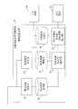
- FIG. 1 shows an example of a network configuration according to the present embodiment.
- the firewall 11 distinguishes between the external network 16 and the internal network 18.
- the firewall 11 is connected to the external network 16, the DMZ (DeMilitarized Zone) network 17 and the internal network 18.
- the firewall 11 and the DMZ network 17 can prevent attack from the external network 16 to the internal network 18.
- the DMZ network 17 includes an intrusion detection device 12, a proxy server 13 and a plurality of monitoring targets 14.
- the intrusion detection device 12 is connected to the firewall 11.
- the intrusion detection device 12 investigates the communication between the external network 16 passing through the firewall 11 and the DMZ network 17 and the communication between the external network 16 and the internal network 18 using a detection rule. Then, when the intrusion detection device 12 detects an attack activity from the external network 16, the intrusion detection device 12 generates a detection log indicating a situation when the attack activity is detected.
- the proxy server 13 connects with the firewall 11.
- the proxy server 13 relays communication from the monitoring target 15 in the internal network 18 to the external network 16. Furthermore, the proxy server 13 relays communication from the external network 16 to the monitoring target 15.
- the monitoring target 14 is connected to the firewall 11.
- the monitoring target 14 includes a mail server, a web server, and the like.
- the internal network 18 includes a plurality of monitoring targets 15 and an attack activity analysis support device 01.
- the monitoring target 15 is connected to the firewall 11.
- the monitoring targets 15 include personal terminals, file servers, AD (Active Directory) servers, and the like.
- the attack activity analysis support apparatus 01 is connected to the internal network 18 and monitors the monitoring target 14 connected to the DMZ network 17 and the monitoring target 15 connected to the internal network 18.
- the attack activity analysis support apparatus 01 stores an analysis history in which a situation and an action to be taken upon detection of an attack activity on the monitoring target 14 and the monitoring target 15 are indicated. Details of the analysis history will be described later.
- the attacking activity analysis support device 01 uses the display device 10 to display an analysis history of past attacking activity similar to the generated attacking activity to the operator.
- An attack activity is any activity that generates an information security threat.
- the attack activities include various unauthorized accesses, attacks called “... Attacks”, preliminary operations of these attacks, and the like.
- the attack activity analysis support device 01 corresponds to an information processing device.
- the operation performed by the attack activity analysis support apparatus 01 corresponds to an information processing method.
- FIG. 2 shows an example of the functional configuration of the attack activity analysis support apparatus 01
- FIG. 10 shows an example of the hardware configuration of the attack activity analysis support apparatus 01.
- the attack activity analysis support device 01 is a computer.
- the attack activity analysis support device 01 includes a processor 101, a storage device 102, a network interface 103, a display interface 104, and an input interface 105 as hardware as shown in FIG. Further, as shown in FIG. 2, the attack activity analysis support apparatus 01 has, as a functional configuration, a warning information collection unit 02, a monitoring information collection unit 03, an analysis information calculation unit 04, a warning importance degree estimation unit 05, a warning information storage unit 06, the monitoring information storage unit 07 and the analysis history storage unit 08 are provided.
- the storage device 102 stores programs for realizing the functions of the warning information collection unit 02, the monitoring information collection unit 03, the analysis information calculation unit 04, and the warning importance degree estimation unit 05.
- FIG. 10 schematically shows a state where the processor 101 is executing a program for realizing the functions of the warning information collection unit 02, the monitoring information collection unit 03, the analysis information calculation unit 04, and the warning importance degree estimation unit 05.
- Programs for realizing the functions of the warning information collection unit 02, the monitoring information collection unit 03, the analysis information calculation unit 04, and the warning importance degree estimation unit 05 correspond to an information processing program.
- the warning information storage unit 06, the monitoring information storage unit 07, and the analysis history storage unit 08 are realized by the storage device 102.
- the network interface 103 is an interface with a communication cable of the internal network 18.
- the display interface 104 is an interface with the display device 10.
- the input interface 105 is an interface with the input device 09.
- the warning information collection unit 02 collects detection logs from the intrusion detection device 12 via the network interface 103. Further, the warning information collection unit 02 stores the collected detection log in the warning information storage unit 06.
- the monitoring information collection unit 03 collects proxy logs from the proxy server 13 via the network interface 103.
- the monitoring information collection unit 03 stores the collected proxy log in the monitoring information storage unit 07.
- the analysis information calculation unit 04 is detected in the past using the situation when the current attack activity, which is the detected attack activity, is detected, and the detection rule.
- the situation when each of a plurality of past attack activities, which are a plurality of attack activities, is detected, and the situation on which the detection rule is premised are analyzed.
- the situation when each of a plurality of past attack activities is detected is described in the analysis history stored in the analysis history storage unit 08. Further, information indicating a situation on which the detection rule is premised is stored, for example, in the storage device 102.
- the analysis information calculation unit 04 analyzes the similarity between the situation when the current attack activity is detected and the situation when each of the plurality of past attack activities is detected.
- the analysis information calculation unit 04 analyzes the degree of similarity between the situation when each of a plurality of past attack activities is detected and the situation where the detection rule is premised. For example, the analysis information calculation unit 04 analyzes the similarity between the time at which the current attack activity is detected and the time zone in which each of a plurality of past attack activities is detected. Further, the analysis information calculation unit 04 analyzes the similarity between the amount of communication when the current attack activity is detected and the amount of communication when each of a plurality of past attack activities is detected. Further, the analysis information calculation unit 04 analyzes the similarity between the time zone in which each of a plurality of past attack activities is detected and the time zone on which the detection rule is premised.
- the analysis information calculation unit 04 analyzes the similarity between the amount of communication when each of a plurality of past attack activities is detected and the amount of communication on which the detection rule is premised. Furthermore, the analysis information calculation unit 04 analyzes the degree of similarity between the types of target devices of each of a plurality of past attack activities and the types of target devices for which the detection rule is premised. Then, based on the analysis result, the analysis information calculation unit 04 selects an arbitrary number of attack activities from among a plurality of past attack activities. The analysis information calculation unit 04 corresponds to a selection unit. The process performed by the analysis information calculation unit 04 corresponds to the selection process.
- the warning importance degree estimation unit 05 presents, to the operator through the display device 10, the countermeasure action taken on the attack activity selected by the analysis information calculation unit 04.
- the warning importance degree estimation unit 05 determines the order between the selected two or more attack activities.
- the warning importance degree estimation unit 05 determines, for example, the order between the selected two or more attack activities based on the importance of the corresponding treatment of each of the selected two or more attack activities.
- the warning importance degree estimation unit 05 presents the response measures taken for the two or more selected attack activities in accordance with the determined order.
- the warning importance degree estimation unit 05 corresponds to a response treatment presentation unit. Further, the process performed by the warning importance degree estimation unit 05 corresponds to a countermeasure presentation process.
- the warning information storage unit 06 stores a detection log.
- the monitoring information storage unit 07 stores proxy logs.
- the analysis history storage unit 08 stores an analysis history.
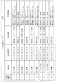
- FIG. 4 shows an example of the analysis history table 203 generated by the analysis information calculation unit 04.
- the analysis history table 203 includes a plurality of analysis histories which are results of analysis of past attack activities.
- Each record in FIG. 4 is an analysis history.
- Each analysis history includes an analysis history number, a warning name, an occurrence time zone, a countermeasure, and analysis information.
- the analysis history number is a serial number automatically set by the analysis information calculation unit 04.
- the response measures are designated by the operator of the attack activity analysis support apparatus 01.
- the warning name and the occurrence time zone are generated from the detection log transmitted from the intrusion detection device 12.
- the intrusion detection device 12 analyzes the communication from the external network 16 to the internal network 18 using a detection rule. When the attack activity is detected, the intrusion detection device 12 identifies the type of attack activity based on the detection rule. The intrusion detection device 12 specifies, for example, which of the Dos attack, port scan, and file transmission the detected attack type is. Then, the intrusion detection device 12 includes the identified type of attack as a warning name in the detection log. Further, the intrusion detection device 12 includes the date and time when the attack activity is detected in the detection log. In addition, the value of analysis information is also generated from the detection log.
- the intrusion detection device 12 identifies the communication destination of the attack activity from the IP address of the transmission destination of the communication data used for the attack activity, and includes the type of the identified communication destination in the detection log. Further, the intrusion detection device 12 may include only the IP address of the transmission destination of the communication data used for the attack activity in the detection log.
- the analysis information calculation unit 04 specifies the type of communication destination from the IP address of the transmission destination included in the detection log. More specifically, the analysis information calculation unit 04 specifies the type of communication destination using the device management table 204 illustrated in FIG. 5.
- the device management table 204 in FIG. 5 indicates the IP addresses of the devices that constitute each of the monitoring target 14 and the monitoring target 15, and the application of each device is shown for each IP address.
- the analysis information calculation unit 04 collates the IP address of the transmission destination indicated by the detection log with the device management table 204 to specify the type of the communication destination.
- the intrusion detection device 12 includes, in the detection log, the traffic of the DMZ network 17 or the internal network 18 when the attack activity is detected.
- the intrusion detection device 12 may not specify at least one of the type of the communication destination and the communication amount. That is, the intrusion detection device 12 does not have to include at least one of the type of communication destination and the communication amount in the detection log.
- the analysis information calculation unit 04 generates analysis information from the proxy log. That is, the proxy server 13 may identify the type of communication destination and the amount of communication when attack activity is detected, and may describe the type and the amount of communication destination identified in the proxy log.
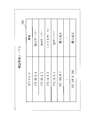
- FIG. 6 shows an example of the similarity history comparison table 205.
- the similarity history comparison table 205 is configured by an analysis history number, a condition based on the detection rule, and a condition at the time of detection of past attack activity.
- the analysis history number indicates the analysis history number of FIG.
- the “conditions assumed by detection rule” indicate the conditions assumed when the detection rule is generated. In the example of FIG. 6, a situation where a detection rule for detecting a DoS attack is assumed is shown.
- the “condition based on the detection rule” is, for example, a time zone, a communication amount, and a target device. In the example of FIG.
- the time zone in which the DoS attack occurs is "10: 00-12: 00"
- the traffic volume at the time of the DoS attack is 5000 access / min
- the DoS attack Assuming that the target device is a Web server, detection rules for detecting DoS attacks are generated.
- a past attack activity determined as a DoS attack that is, a past attack activity detected by applying a detection rule for detecting a Dos attack is applied. The situation is shown.
- the “condition at the time of detection of past attack activity” is, for example, a time zone, a traffic amount, and a target device.
- the time slot in which the DoS attack of analysis history number 1 is detected is “10: 00-12: 00”, and the traffic volume when the DoS attack is detected is 5500 access / min.
- the device targeted by the attack is a web server.
- the similar history comparison table 205 is used to compare, for each past attack activity, the situation assumed by the detection rule with the situation when each attack activity was detected.
- FIG. 6 shows a similar history comparison table 205 for DoS attacks, a similar history comparison table 205 exists for other attack activities (port scan, file transmission, etc.).
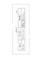
- FIG. 9 shows an example of the detection log 301 transmitted from the intrusion detection device 12 to the attack activity analysis support device 01 when the intrusion detection device 12 newly detects an attack activity.
- the detection log 301 includes a warning name, date and time of occurrence, and analysis information.
- the meanings of the warning name, the date and time of occurrence, and the analysis information are the same as those shown in FIG.
- the warning name, occurrence date and time, and analysis information shown in FIG. 4 are attributes of past attack activity detected in the past, whereas the warning name, occurrence date and time and analysis information shown in FIG. 9 are newly detected. It is an attribute of the current attack activity.
- FIG. 9 shows an example in which the value of analysis information is also transmitted from the intrusion detection device 12 as the detection log 301, as described above, the value of analysis information may be transmitted from the proxy server 13 as a proxy log.
- FIG. 3 is a flowchart showing an operation example of the attack activity analysis support device 01.
- the analysis information calculation unit 04 If the analysis history table 203 shown in FIG. 4 is not stored in the analysis history storage unit 08, the analysis information calculation unit 04 generates an analysis history table 203 as an initial setting (step S001). Also, the analysis information calculation unit 04 generates the device management table 204 of the monitoring target 14 and the monitoring target 15 if necessary.
- the warning information collection unit 02 periodically receives a detection log from the intrusion detection device 12, and stores the received detection log in the warning information storage unit 06 (step S002).
- the intrusion detection device 12 periodically transmits a detection log even when attack activity is not detected. In the case where the attack activity is not detected, the intrusion detection device 12 transmits a detection log different from the detection log when the attack activity is detected. For example, the intrusion detection device 12 transmits a detection log in which the warning name column in FIG. 9 is blank.
- the warning information collection unit 02 determines whether or not the received detection log notifies the detection of the attack activity (step S003). For example, the warning information collection unit 02 determines whether a value is set in the column of the warning name of the received detection log.
- step S 004 If the received detection log is a detection log notifying of detection of attack activity, the process proceeds to step S 004. On the other hand, if the received detection log is not a detection log notifying of detection of attack activity, the process returns to step S002.
- the warning information collection unit 02 has received the detection log 301 shown in FIG. That is, it is assumed that the intrusion detection device 12 detects a DoS attack.
- step S003 is YES, that is, when the attack activity is detected in the intrusion detection device 12, the warning information collection unit 02 outputs the detection log received from the intrusion detection device 12 to the analysis information calculation unit 04.
- the analysis information calculation unit 04 acquires, from the analysis history storage unit 08, the analysis history table 203 corresponding to the warning name indicated in the detection log acquired from the warning information collection unit 02 (step S004). Specifically, the analysis information calculation unit 04 acquires the analysis history table 203 of FIG. 4 corresponding to the DoS attack which is the warning name of the detection log 301 of FIG. 9.
- the analysis information calculation unit 04 extracts, from the analysis history table 203, an analysis history in which a communication destination common to the communication destination shown in the detection log is shown (step S005).
- the analysis information calculation unit 04 extracts the analysis history of analysis history numbers 1, 3, 4, 5, and 10 whose communication destination is the Web server.
- the analysis information calculation unit 04 analyzes the similarity of the analysis history extracted in step S005 (step S006).
- the similarity history comparison table 205 is used for analysis of similarity. Specifically, the analysis information calculation unit 04 detects the time at which the current attack activity shown in the detection log was detected, and the analysis history numbers 1, 3, 4, 5, and 10 Calculate the degree of similarity with the time zone indicated in the "occurrence time zone" of the situation. Also, the analysis information calculation unit 04 determines the amount of communication when the current attack activity shown in the detection log is detected and the status of the analysis history numbers 1, 3, 4, 5, and 10 “when the attack activity was detected in the past.
- the analysis information calculation unit 04 presupposes the time zone indicated in the "occurrence time zone” and the "detection rule” of the "the situation at the time of detection of the past attack activity” of the analysis history numbers 1, 3, 4, 5, and 10. Calculate the degree of similarity with the time zone indicated in the "occurrence time zone” of the situation. Further, the analysis information calculation unit 04 assumes that the communication amount indicated by the “communication amount” in “the situation at the time of detection of the past attack activity” and “the detection rule” in the analysis history numbers 1, 3, 4, 5, and 10 Calculate the degree of similarity with the amount of communication indicated in "the amount of communication” in the situation.
- the analysis information calculation unit 04 presupposes the types of devices indicated in the “target” of “the situation at the time of detection of the past attack activity” and “the detection rule” in the analysis history numbers 1, 3, 4, 5, and 10. Calculate the degree of similarity with the type of device indicated in "Target”.
- the occurrence time is “10:18”, and the communication amount is “5500 access / minute”. Therefore, the analysis history numbers 1, 3 and 4 have high similarity in relation to the current attack activity. Furthermore, in the “condition based on the detection rule” in FIG. 6, the occurrence time zone is “10: 00-12: 00”, “communication amount” is “5000”, and “target” is “Web”. is there. For this reason, high similarity is given to analysis history numbers 1, 3 and 4 also in relation to the detection rule. In the present embodiment, the calculation method of the degree of similarity itself does not matter. As a result, in the example of FIG.
- the analysis information calculation unit 04 selects the analysis histories of the analysis history numbers 1, 3, and 4 having high similarity as the history suitable for analysis of the newly generated detection log. Then, the analysis information calculation unit 04 outputs the analysis histories (corresponding records in FIG. 4) of the analysis history numbers 1, 3 and 4 to the warning importance degree estimation unit 05.
- the warning importance degree estimation unit 05 acquires an analysis history from the analysis information calculation unit 04, and presents the acquired analysis history to the operator via the display device 10 according to the acquired importance of the analysis history (step S007).
- the warning importance degree estimation unit 05 presents the acquired analysis history to the operator via the display device 10.
- the warning importance degree estimation unit 05 determines the importance of the analysis history. Then, the warning importance degree estimation unit 05 determines the order among the plurality of analysis histories in order of importance, and presents the plurality of analysis histories to the operator via the display device 10 according to the determined order.
- the determination method of the importance of analysis history is as follows.
- the warning importance degree estimation unit 05 rearranges, from the item of necessity of the countermeasure described in the “action corresponding to” in the analysis history, the analysis history in which the countermeasure is necessary to the top.
- the analysis history in which “report to customer” is described in the item of the treatment content described in “response treatment” in the analysis history is sorted in the upper rank.
- FIG. 7 shows the order of the analysis history notified to the warning importance degree estimation unit 05.
- the analysis information calculation unit 04 notifies the warning importance degree estimation unit 05 in the order of analysis history numbers 1, 3, and 4.
- FIG. 8 shows the order of the analysis history after the order is changed by the warning importance degree estimation unit 05.
- the warning importance degree estimation unit 05 presents the operator with a plurality of analysis histories in the order shown in FIG. The operator can consider the response action to the newly detected current attack activity, with reference to the description of the “response action” column of the analysis history presented from the warning importance degree estimation unit 05. Note that, after the operator determines the action to be taken against the newly detected current attack activity, the analysis information calculation unit 04 displays the description content of the detection log 301 of FIG. 9 and the action taken by the operator. A new record is added to the analysis history table 203.
- the situation when the current attack activity is detected, the situation when each of a plurality of past attack activities is detected, and the situation where the detection rule is premised are analyzed. Do. Then, in the present embodiment, a past attack activity suitable for the current attack activity is selected from a plurality of past attack activities, and a countermeasure to the selected past attack activity is presented. Therefore, according to the present embodiment, even inexperienced analysts (operators) can take appropriate measures for the current attack activities.
- the processor 101 illustrated in FIG. 10 performs an IC (Integrated Circuit) that performs processing. Circuit).
- the processor 101 is a CPU, a DSP (Digital Signal Processor), or the like.
- the storage device 102 illustrated in FIG. 3 is a random access memory (RAM), a read only memory (ROM), a flash memory, a hard disk drive (HDD), or the like.
- a network interface 103 illustrated in FIG. 3 is an electronic circuit that executes data communication processing.
- the network interface 103 is, for example, a communication chip or a NIC (Network Interface Card).
- the storage device 102 also stores an OS (Operating System). Then, at least a part of the OS is executed by the processor 101.
- the processor 101 executes a program that implements the functions of the warning information collection unit 02, the monitoring information collection unit 03, the analysis information calculation unit 04, and the warning importance degree estimation unit 05 while executing at least a part of the OS.
- As the processor 101 executes the OS task management, memory management, file management, communication control and the like are performed. Further, at least one of information, data, a signal value, and a variable value indicating a result of processing of the warning information collection unit 02, the monitoring information collection unit 03, the analysis information calculation unit 04, and the warning importance degree estimation unit 05 is the storage device 102.
- the programs for realizing the functions of the warning information collection unit 02, the monitoring information collection unit 03, the analysis information calculation unit 04, and the warning importance degree estimation unit 05 are a magnetic disk, a flexible disk, an optical disk, a compact disk, Blu-ray (registered trademark) It may be stored in a portable storage medium such as a disc or a DVD.
- the “unit” of the warning information collection unit 02, the monitoring information collection unit 03, the analysis information calculation unit 04, and the warning importance degree estimation unit 05 is replaced with a “circuit” or a “process” or a “procedure” or a “process”. It is also good.
- the attack activity analysis support device 01 may be realized by a processing circuit.
- the processing circuit is, for example, a logic integrated circuit (IC), a gate array (GA), an application specific integrated circuit (ASIC), a field-programmable gate (FPGA). Array).
- the warning information collection unit 02, the monitoring information collection unit 03, the analysis information calculation unit 04, and the warning importance degree estimation unit 05 are each realized as part of a processing circuit.
- processing circuit the upper concept of the processor, the memory, the combination of the processor and the memory, and the processing circuit. That is, the processor, the memory, the combination of the processor and the memory, and the processing circuit are specific examples of the "processing circuit".
- 01 attack activity analysis support device 02 warning information collection unit, 03 monitoring information collection unit, 04 analysis information calculation unit, 05 warning importance degree estimation unit, 06 warning information storage unit, 07 monitoring information storage unit, 08 analysis history storage unit, 09 input device, 10 display device, 11 firewall, 12 intrusion detection device, 13 proxy server, 14 monitored object, 15 monitored object, 16 external network, 17 DMZ network, 18 internal network, 101 processor, 102 storage device, 103 network interface , 104 display interface, 105 input interface.
Abstract
検知ルールを用いて攻撃活動が検知された場合に、分析情報算出部(04)は、検知された攻撃活動である現在の攻撃活動が検知された際の状況と、検知ルールを用いて過去に検知された複数の攻撃活動である複数の過去の攻撃活動のそれぞれが検知された際の状況と、検知ルールが前提としている状況とを分析し、分析結果に基づき、複数の過去の攻撃活動の中から任意数の攻撃活動を選択する。警告重要度推定部(05)は、分析情報算出部(04)により選択された攻撃活動に対して行われた対応処置を提示する。
Description
本発明は、情報システムに対する攻撃活動を検知する技術に関する。
本発明に関連する技術として、特許文献1~3に開示の技術がある。
特許文献1では、サーバーが送信するURL(Uniform Resource Locator)の宛先又は変数値から特徴量が算出され、監視装置が持つシグネチャに類似するURLであるかが判定される。これにより、監視装置が持つシグネチャに完全に一致しないURLの宛先又は変数値を用いた攻撃の通信を検知し、端末やサーバーへの未知の攻撃を検知することが可能である。特許文献1のシグネチャの類似を判定する機能の目的は新たな攻撃パターンを追加することである。
特許文献2では、CPU(Central Processing Unit)利用率に代表される計算機のリソース情報がセキュリティ侵害行為で変動することが多いことに着眼し、現在のCPU使用率と過去のCPU使用率の特徴量が算出される。そして、算出結果がリソース情報の条件を記載したルールと合致した場合に、異常と判定される。これにより、大量の様々なログ情報を分析することなく計算機システムへのセキュリティ侵害行為に対処することが可能である。
遠隔からメンテナンス指示を出す際に、監視画像ではメンテナンス箇所を誤りなく指示することが困難であるという課題がある。これに対して特許文献3では、監視対象設備の画像情報と監視対象設備のCAD(Computer-Aided Design)情報を組み合わせて座標情報が作成され、座標情報を用いてメンテナンス箇所が指示される。
攻撃活動を監視するセキュリティ監視センターでは、アナリストが、検知された攻撃活動への対応処置を決定する。より具体的には、アナリストはセキュリティ監視センターに保管されている過去の攻撃活動の履歴をもとに、検知された攻撃活動に対する対応処置を決定する。ただし、同じ攻撃活動であっても、監視先のネットワークの構成及び対処したアナリストの経験等により異なる対応処置が選択される。このため、同じ攻撃活動に対して対応処置が異なる履歴が複数存在することになる。
経験の浅いアナリストが対応にあたった場合に、対応処置が異なる複数の履歴のうちのどの履歴を参考にすべきかを適切に判断することが困難であるという課題がある。また、複数の履歴から現在の攻撃活動に適した履歴を選択できないと、誤った対応処置がとられ、攻撃活動に有効に対処できないという課題がある。
特許文献1~3では、これらの課題を解決することはできない。
経験の浅いアナリストが対応にあたった場合に、対応処置が異なる複数の履歴のうちのどの履歴を参考にすべきかを適切に判断することが困難であるという課題がある。また、複数の履歴から現在の攻撃活動に適した履歴を選択できないと、誤った対応処置がとられ、攻撃活動に有効に対処できないという課題がある。
特許文献1~3では、これらの課題を解決することはできない。
本発明は、上記の課題を解決することを主な目的とする。具体的には、検知された攻撃活動に対して適切な対応処置がとられるようにすることを主な目的する。
本発明に係る情報処理装置は、
検知ルールを用いて攻撃活動が検知された場合に、検知された攻撃活動である現在の攻撃活動が検知された際の状況と、前記検知ルールを用いて過去に検知された複数の攻撃活動である複数の過去の攻撃活動のそれぞれが検知された際の状況と、前記検知ルールが前提としている状況とを分析し、分析結果に基づき、前記複数の過去の攻撃活動の中から任意数の攻撃活動を選択する選択部と、
前記選択部により選択された攻撃活動に対して行われた対応処置を提示する対応処置提示部とを有する。
検知ルールを用いて攻撃活動が検知された場合に、検知された攻撃活動である現在の攻撃活動が検知された際の状況と、前記検知ルールを用いて過去に検知された複数の攻撃活動である複数の過去の攻撃活動のそれぞれが検知された際の状況と、前記検知ルールが前提としている状況とを分析し、分析結果に基づき、前記複数の過去の攻撃活動の中から任意数の攻撃活動を選択する選択部と、
前記選択部により選択された攻撃活動に対して行われた対応処置を提示する対応処置提示部とを有する。
本発明では、現在の攻撃活動が検知された際の状況と、複数の過去の攻撃活動のそれぞれが検知された際の状況と、検知ルールが前提とする状況とを分析する。そして、本発明では、複数の過去の攻撃活動の中から現在の攻撃活動に適した過去の攻撃活動が選択され、選択された過去の攻撃活動に対する対応処置が提示される。
このため、本発明によれば、アナリストは、検知された攻撃活動に適した対応処置をとることができる。
このため、本発明によれば、アナリストは、検知された攻撃活動に適した対応処置をとることができる。
以下、本発明の実施の形態について、図を用いて説明する。以下の実施の形態の説明及び図面において、同一の符号を付したものは、同一の部分または相当する部分を示す。
実施の形態1.
***構成の説明***
図1は、本実施の形態に係るネットワーク構成例を示す。
***構成の説明***
図1は、本実施の形態に係るネットワーク構成例を示す。
本実施の形態では、ファイアウォール11により、外部ネットワーク16と内部ネットワーク18とが区別されている。ファイアウォール11は、外部ネットワーク16とDMZ(DeMilitarized Zone)ネットワーク17と内部ネットワーク18とに接続されている。ファイアウォール11及びDMZネットワーク17により、外部ネットワーク16から内部ネットワーク18への攻撃活動を防ぐことができる。
DMZネットワーク17には、侵入検知装置12、プロキシサーバー13及び複数の監視対象14が含まれる。
侵入検知装置12はファイアウォール11と接続する。
侵入検知装置12は、ファイアウォール11を通過する外部ネットワーク16とDMZネットワーク17との間の通信と、外部ネットワーク16と内部ネットワーク18との間の通信を検知ルールを用いて調査する。そして、侵入検知装置12は、外部ネットワーク16からの攻撃活動を検知した場合に、当該攻撃活動を検知した際の状況が示される検知ログを生成する。
侵入検知装置12は、ファイアウォール11を通過する外部ネットワーク16とDMZネットワーク17との間の通信と、外部ネットワーク16と内部ネットワーク18との間の通信を検知ルールを用いて調査する。そして、侵入検知装置12は、外部ネットワーク16からの攻撃活動を検知した場合に、当該攻撃活動を検知した際の状況が示される検知ログを生成する。
プロキシサーバー13は、ファイアウォール11と接続する。
プロキシサーバー13は、内部ネットワーク18内の監視対象15から外部ネットワーク16への通信を中継する。さらに、プロキシサーバー13は、外部ネットワーク16から監視対象15への通信を中継する。
プロキシサーバー13は、内部ネットワーク18内の監視対象15から外部ネットワーク16への通信を中継する。さらに、プロキシサーバー13は、外部ネットワーク16から監視対象15への通信を中継する。
監視対象14はファイアウォール11と接続する。
監視対象14にはメールサーバー、Webサーバー等が含まれる。
監視対象14にはメールサーバー、Webサーバー等が含まれる。
内部ネットワーク18には、複数の監視対象15と攻撃活動分析支援装置01が含まれる。
監視対象15は、ファイアウォール11と接続する。
監視対象15には個人端末、ファイルサーバー、AD(Active Directory)サーバー等が含まれる。
監視対象15は、ファイアウォール11と接続する。
監視対象15には個人端末、ファイルサーバー、AD(Active Directory)サーバー等が含まれる。
攻撃活動分析支援装置01は、内部ネットワーク18に接続し、DMZネットワーク17に接続された監視対象14及び内部ネットワーク18に接続された監視対象15を監視する。
攻撃活動分析支援装置01は、監視対象14及び監視対象15への攻撃活動が検知された際の状況及び対応処置が示される分析履歴を記憶している。分析履歴の詳細は後述する。
外部ネットワーク16からDMZネットワーク17又は内部ネットワーク18に対する攻撃活動が発生した場合に、攻撃活動分析支援装置01は発生した攻撃活動に類似する過去の攻撃活動の分析履歴を表示装置10を用いてオペレーターに提示する。
なお、攻撃活動とは、情報セキュリティ上の脅威を発生させるあらゆる活動である。攻撃活動には、各種の不正アクセス、「・・・攻撃」と称される攻撃、これら攻撃の予備動作等が含まれる。
なお、攻撃活動分析支援装置01は情報処理装置に相当する。また、攻撃活動分析支援装置01により行われる動作は、情報処理方法に相当する。
図2は、攻撃活動分析支援装置01の機能構成例を示し、図10は、攻撃活動分析支援装置01のハードウェア構成例を示す。
本実施の形態に係る攻撃活動分析支援装置01は、コンピュータである。
攻撃活動分析支援装置01は、ハードウェアとして、図10に示すように、プロセッサ101、記憶装置102、ネットワークインタフェース103、表示インタフェース104及び入力インタフェース105を備える。
また、攻撃活動分析支援装置01は、機能構成として、図2に示すように、警告情報収集部02、監視情報収集部03、分析情報算出部04、警告重要度推定部05、警告情報蓄積部06、監視情報蓄積部07及び分析履歴蓄積部08を備える。
記憶装置102には、警告情報収集部02、監視情報収集部03、分析情報算出部04及び警告重要度推定部05の機能を実現するプログラムが記憶されている。
そして、プロセッサ101がこれらプログラムを実行して、後述する警告情報収集部02、監視情報収集部03、分析情報算出部04及び警告重要度推定部05の動作を行う。
図10では、プロセッサ101が警告情報収集部02、監視情報収集部03、分析情報算出部04及び警告重要度推定部05の機能を実現するプログラムを実行している状態を模式的に表している。
警告情報収集部02、監視情報収集部03、分析情報算出部04及び警告重要度推定部05の機能を実現するプログラムは、情報処理プログラムに相当する。
また、警告情報蓄積部06、監視情報蓄積部07及び分析履歴蓄積部08は、記憶装置102により実現される。
ネットワークインタフェース103は、内部ネットワーク18の通信ケーブルとのインタフェースである。
表示インタフェース104は、表示装置10とのインタフェースである。
入力インタフェース105は、入力装置09とのインタフェースである。
図2において、警告情報収集部02は、ネットワークインタフェース103を介して侵入検知装置12から検知ログを収集する。また、警告情報収集部02は、収集した検知ログを警告情報蓄積部06に格納する。
監視情報収集部03は、ネットワークインタフェース103を介してプロキシサーバー13からプロキシログを収集する。監視情報収集部03は、収集したプロキシログを監視情報蓄積部07に格納する。
分析情報算出部04は、侵入検知装置12により攻撃活動が検知された場合に、検知された攻撃活動である現在の攻撃活動が検知された際の状況と、検知ルールを用いて過去に検知された複数の攻撃活動である複数の過去の攻撃活動のそれぞれが検知された際の状況と、検知ルールが前提としている状況とを分析する。なお、複数の過去の攻撃活動のそれぞれが検知された際の状況は、分析履歴蓄積部08に蓄積されている分析履歴に記載されている。また、検知ルールが前提としている状況が示される情報は、例えば、記憶装置102で記憶されている。
分析情報算出部04は、具体的には、現在の攻撃活動が検知された際の状況と複数の過去の攻撃活動のそれぞれが検知された際の状況との類似度を分析する。また、分析情報算出部04は、複数の過去の攻撃活動のそれぞれが検知された際の状況と検知ルールが前提としている状況との類似度を分析する。例えば、分析情報算出部04は、現在の攻撃活動が検知された時刻と複数の過去の攻撃活動のそれぞれが検知された時間帯との類似度を分析する。また、分析情報算出部04は、現在の攻撃活動が検知された際の通信量と複数の過去の攻撃活動のそれぞれが検知された際の通信量との類似度を分析する。また、分析情報算出部04は、複数の過去の攻撃活動のそれぞれが検知された時間帯と検知ルールが前提とする時間帯との類似度を分析する。また、分析情報算出部04は、複数の過去の攻撃活動のそれぞれが検知された際の通信量と検知ルールが前提とする通信量との類似度を分析する。更に、分析情報算出部04は、複数の過去の攻撃活動のそれぞれのターゲットの機器の種類と検知ルールが前提とするターゲットの機器の種類との類似度を分析する。
そして、分析情報算出部04は、分析結果に基づき、複数の過去の攻撃活動の中から任意数の攻撃活動を選択する。
分析情報算出部04は選択部に相当する。また、分析情報算出部04により行われる処理は、選択処理に相当する。
警告重要度推定部05は、分析情報算出部04により選択された攻撃活動に対して行われた対応処置を表示装置10を通じてオペレーターに提示する。
分析情報算出部04により2以上の攻撃活動が選択された場合に、警告重要度推定部05は、選択された2以上の攻撃活動の間の序列を決定する。警告重要度推定部05は、例えば、選択された2以上の攻撃活動の各々の対応処置の重要度に基づき、選択された2以上の攻撃活動の間の序列を決定する。そして、警告重要度推定部05は、決定した序列に従って、選択された2以上の攻撃活動に対して行われた対応処置を提示する。
警告重要度推定部05は、対応処置提示部に相当する。また、警告重要度推定部05により行われる処理は、対応処置提示処理に相当する。
分析情報算出部04により2以上の攻撃活動が選択された場合に、警告重要度推定部05は、選択された2以上の攻撃活動の間の序列を決定する。警告重要度推定部05は、例えば、選択された2以上の攻撃活動の各々の対応処置の重要度に基づき、選択された2以上の攻撃活動の間の序列を決定する。そして、警告重要度推定部05は、決定した序列に従って、選択された2以上の攻撃活動に対して行われた対応処置を提示する。
警告重要度推定部05は、対応処置提示部に相当する。また、警告重要度推定部05により行われる処理は、対応処置提示処理に相当する。
警告情報蓄積部06は、検知ログを蓄積する。
監視情報蓄積部07は、プロキシログを蓄積する。
分析履歴蓄積部08は、分析履歴を蓄積する。
次に、本実施の形態で扱われるデータを説明する。
図4は、分析情報算出部04が生成する分析履歴テーブル203の例を示す。
図4に示すように、分析履歴テーブル203には、過去の攻撃活動を分析した結果である分析履歴が複数含まれる。図4の各レコードが分析履歴である。各分析履歴には、分析履歴番号、警告名、発生時間帯、対応処置、解析情報が含まれる。
分析履歴番号は、分析情報算出部04により自動的に設定される通し番号である。
対応処置は、攻撃活動分析支援装置01のオペレーターにより指定される。
対応処置は、攻撃活動分析支援装置01のオペレーターにより指定される。
警告名、発生時間帯は、侵入検知装置12から送信された検知ログから生成される。侵入検知装置12は、外部ネットワーク16から内部ネットワーク18への通信を検知ルールを用いて解析する。攻撃活動を検知した場合に、侵入検知装置12は、検知ルールに基づき、攻撃活動の種類を特定する。侵入検知装置12は、検知した攻撃の種類が、例えば、Dos攻撃、ポートスキャン、ファイル送信のうちのいずれであるかを特定する。そして、侵入検知装置12は、特定した攻撃の種類を警告名として検知ログに含ませる。また、侵入検知装置12は、攻撃活動を検知した日時を検知ログに含ませる。
また、解析情報の値も、検知ログから生成される。例えば、侵入検知装置12は、攻撃活動に用いられる通信データの送信先のIPアドレスから攻撃活動の通信先を特定し、特定した通信先の種類を検知ログに含ませる。また、侵入検知装置12は、攻撃活動に用いられる通信データの送信先のIPアドレスのみを検知ログに含ませるようにしてもよい。この場合は、分析情報算出部04が検知ログに含まれる送信先のIPアドレスから通信先の種類を特定する。より具体的には、分析情報算出部04は図5に例示する機器管理テーブル204を用いて通信先の種類を特定する。図5の機器管理テーブル204には、監視対象14及び監視対象15のそれぞれを構成する機器のIPアドレスが示され、IPアドレスごとに、各機器の用途が示される。機器の用途はメールサーバー、Webサーバー、個人端末、ファイルサーバー、ADサーバー等である。分析情報算出部04は、検知ログで示される送信先のIPアドレスを機器管理テーブル204と照合して、通信先の種類を特定する。
また、侵入検知装置12は、攻撃活動を検知した際のDMZネットワーク17または内部ネットワーク18の通信量を検知ログに含ませる。
なお、侵入検知装置12は、通信先の種類及び通信量の少なくともいずれかを特定しなくてもよい。つまり、侵入検知装置12は、通信先の種類及び通信量の少なくともいずれかを検知ログに含めなくてもよい。この場合は、分析情報算出部04は、プロキシログから解析情報を生成する。
つまり、プロキシサーバー13は、通信先の種類及び攻撃活動が検知された際の通信量を特定し、特定した通信先の種類及び通信量をプロキシログに記載してもよい。
図6は、類似履歴比較テーブル205の例を示す。
図6に示すように、類似履歴比較テーブル205は、分析履歴番号、検知ルールが前提とする状況、過去の攻撃活動の検知時の状況で構成される。
分析履歴番号は、図5の分析履歴番号を示す。
「検知ルールが前提とする状況」では、検知ルールが生成される際に前提とされた状況が示される。図6の例では、DoS攻撃を検知するための検知ルールが前提とする状況が示される。「検知ルールが前提とする状況」は、例えば、時間帯と通信量とターゲットの機器である。図6の例では、DoS攻撃が発生する時間帯が「10:00-12:00」であり、また、DoS攻撃が発生する際の通信量が5000アクセス/分であり、また、DoS攻撃がターゲットにする機器がWebサーバーであるとの前提で、DoS攻撃を検知するための検知ルールが生成されている。
「過去の攻撃活動の検知時の状況」では、DoS攻撃と判定された過去の攻撃活動、すなわち、Dos攻撃を検知するための検知ルールが適用されて検知された過去の攻撃活動の検知時の状況が示される。「過去の攻撃活動の検知時の状況」は、例えば、時間帯と通信量とターゲットの機器である。分析履歴番号:1のDoS攻撃が検知された時間帯は「10:00-12:00」であり、当該DoS攻撃が検知された際の通信量は5500アクセス/分であり、また、当該DoS攻撃がターゲットにした機器はWebサーバーである。
類似履歴比較テーブル205は、過去の攻撃活動ごとに、検知ルールが前提とする状況と、各攻撃活動が検知された際の状況との比較に用いられる。
図6は、DoS攻撃についての類似履歴比較テーブル205を示すが、他の攻撃活動(ポートスキャン、ファイル送信等)についても、同様の類似履歴比較テーブル205が存在する。
図9は、侵入検知装置12が新たに攻撃活動を検知した際に侵入検知装置12から攻撃活動分析支援装置01に送信される検知ログ301の例を示す。
検知ログ301は、警告名、発生日時及び解析情報で構成される。
警告名、発生日時及び解析情報のそれぞれの意味は、図4に示すものと同じである。
図4に示す警告名、発生日時及び解析情報は、過去に検知された過去の攻撃活動の属性であるのに対し、図9に示す警告名、発生日時及び解析情報は、新たに検知された現在の攻撃活動の属性である。
図9では、解析情報の値も検知ログ301として侵入検知装置12から送信される例を示すが、前述したように、解析情報の値はプロキシログとしてプロキシサーバー13から送信されてもよい。
警告名、発生日時及び解析情報のそれぞれの意味は、図4に示すものと同じである。
図4に示す警告名、発生日時及び解析情報は、過去に検知された過去の攻撃活動の属性であるのに対し、図9に示す警告名、発生日時及び解析情報は、新たに検知された現在の攻撃活動の属性である。
図9では、解析情報の値も検知ログ301として侵入検知装置12から送信される例を示すが、前述したように、解析情報の値はプロキシログとしてプロキシサーバー13から送信されてもよい。
***動作の説明***
次に、本実施の形態に係る攻撃活動分析支援装置01の動作例を説明する。
図3は、攻撃活動分析支援装置01の動作例を示すフローチャートである。
次に、本実施の形態に係る攻撃活動分析支援装置01の動作例を説明する。
図3は、攻撃活動分析支援装置01の動作例を示すフローチャートである。
図4に示す分析履歴テーブル203が分析履歴蓄積部08に蓄積されていなければ、分析情報算出部04が初期設定として、分析履歴テーブル203を生成する(ステップS001)。
また、分析情報算出部04は、必要であれば、監視対象14と監視対象15の機器管理テーブル204を生成する。
また、分析情報算出部04は、必要であれば、監視対象14と監視対象15の機器管理テーブル204を生成する。
警告情報収集部02は侵入検知装置12から定期的に検知ログを受信し、受信した検知ログを警告情報蓄積部06に格納する(ステップS002)。
侵入検知装置12は、攻撃活動を検知していない場合にも検知ログを定期的に送信する。侵入検知装置12は、攻撃活動を検知していない場合は、攻撃活動を検知した場合の検知ログとは異なる検知ログを送信する。例えば、侵入検知装置12は、図9の警告名の欄が空欄の検知ログを送信する。
警告情報収集部02は、受信した検知ログが攻撃活動の検知を通知する検知ログが否かを判定する(ステップS003)。例えば、警告情報収集部02は、受信した検知ログの警告名の欄に値が設定されているか否かを判定する。
受信した検知ログが攻撃活動の検知を通知する検知ログであれば、処理がステップS004に移行する。一方、受信した検知ログが攻撃活動の検知を通知する検知ログでなければ、処理がステップS002に戻る。
ここでは、警告情報収集部02が図9に示す検知ログ301を受信したと仮定する。つまり、侵入検知装置12によりDoS攻撃が検知されたものとする。
ステップS003がYESの場合、すなわち、侵入検知装置12において攻撃活動が検知された場合は、警告情報収集部02は、侵入検知装置12から受信した検知ログを分析情報算出部04に出力する。
分析情報算出部04は、分析履歴蓄積部08から、警告情報収集部02から取得した検知ログに示される警告名に対応する分析履歴テーブル203を取得する(ステップS004)。具体的には、分析情報算出部04は、図9の検知ログ301の警告名であるDoS攻撃に対応する図4の分析履歴テーブル203を取得する。
分析情報算出部04は、分析履歴蓄積部08から、警告情報収集部02から取得した検知ログに示される警告名に対応する分析履歴テーブル203を取得する(ステップS004)。具体的には、分析情報算出部04は、図9の検知ログ301の警告名であるDoS攻撃に対応する図4の分析履歴テーブル203を取得する。
次に、分析情報算出部04は、分析履歴テーブル203から、検知ログに示される通信先と共通の通信先が示される分析履歴を抽出する(ステップS005)。
図4の例では、分析情報算出部04は、通信先がWebサーバーである分析履歴番号1、3、4、5、10の分析履歴を抽出する。
図4の例では、分析情報算出部04は、通信先がWebサーバーである分析履歴番号1、3、4、5、10の分析履歴を抽出する。
次に、分析情報算出部04は、ステップS005で抽出した分析履歴の類似度を分析する(ステップS006)。
類似度の分析には、類似履歴比較テーブル205が用いられる。具体的には、分析情報算出部04は、検知ログに示される現在の攻撃活動が検知された時刻と、分析履歴番号1、3、4、5、10の「過去の攻撃活動の検知時の状況」の「発生時間帯」に示される時間帯との類似度を算出する。また、分析情報算出部04は、検知ログに示される現在の攻撃活動が検知された際の通信量と分析履歴番号1、3、4、5、10の「過去の攻撃活動の検知時の状況」の「通信量」に示される通信量との類似度を算出する。また、分析情報算出部04は、分析履歴番号1、3、4、5、10の「過去の攻撃活動の検知時の状況」の「発生時間帯」に示される時間帯と「検知ルールが前提とする状況」の「発生時間帯」に示される時間帯との類似度を算出する。また、分析情報算出部04は、分析履歴番号1、3、4、5、10の「過去の攻撃活動の検知時の状況」の「通信量」に示される通信量と「検知ルールが前提とする状況」の「通信量」に示される通信量との類似度を算出する。更に、分析情報算出部04は、分析履歴番号1、3、4、5、10の「過去の攻撃活動の検知時の状況」の「ターゲット」に示される機器の種類と「検知ルールが前提とする状況」「ターゲット」に示される機器の種類との類似度を算出する。
類似度の分析には、類似履歴比較テーブル205が用いられる。具体的には、分析情報算出部04は、検知ログに示される現在の攻撃活動が検知された時刻と、分析履歴番号1、3、4、5、10の「過去の攻撃活動の検知時の状況」の「発生時間帯」に示される時間帯との類似度を算出する。また、分析情報算出部04は、検知ログに示される現在の攻撃活動が検知された際の通信量と分析履歴番号1、3、4、5、10の「過去の攻撃活動の検知時の状況」の「通信量」に示される通信量との類似度を算出する。また、分析情報算出部04は、分析履歴番号1、3、4、5、10の「過去の攻撃活動の検知時の状況」の「発生時間帯」に示される時間帯と「検知ルールが前提とする状況」の「発生時間帯」に示される時間帯との類似度を算出する。また、分析情報算出部04は、分析履歴番号1、3、4、5、10の「過去の攻撃活動の検知時の状況」の「通信量」に示される通信量と「検知ルールが前提とする状況」の「通信量」に示される通信量との類似度を算出する。更に、分析情報算出部04は、分析履歴番号1、3、4、5、10の「過去の攻撃活動の検知時の状況」の「ターゲット」に示される機器の種類と「検知ルールが前提とする状況」「ターゲット」に示される機器の種類との類似度を算出する。
図9の検知ログ301では、発生時刻は「10:18」であり、通信量は「5500アクセス/分」である。このため、現在の攻撃活動との関係では、分析履歴番号1、3、4に高い類似度が付与される。また、図6の「検知ルールが前提とする状況」では発生時間帯は「10:00-12:00」であり、「通信量」は「5000」であり、「ターゲット」は「Web」である。このため、検知ルールとの関係でも、分析履歴番号1、3、4に高い類似度が付与される。なお、本実施の形態では、類似度の算出方法自体は問わない。
この結果、図6の例では、分析情報算出部04は、新規に発生した検知ログの分析に適した履歴として、類似度の高い分析履歴番号1、3、4の分析履歴を選択する。
そして、分析情報算出部04は、分析履歴番号1、3、4の分析履歴(図4の該当するレコード)を警告重要度推定部05に出力する。
この結果、図6の例では、分析情報算出部04は、新規に発生した検知ログの分析に適した履歴として、類似度の高い分析履歴番号1、3、4の分析履歴を選択する。
そして、分析情報算出部04は、分析履歴番号1、3、4の分析履歴(図4の該当するレコード)を警告重要度推定部05に出力する。
警告重要度推定部05は、分析情報算出部04から分析履歴を取得し、取得した分析履歴の重要度に従って、取得した分析履歴を表示装置10を介してオペレーターに提示する(ステップS007)。
警告重要度推定部05は、分析情報算出部04から取得した分析履歴が一つである場合は、取得した分析履歴を表示装置10を介してオペレーターに提示する。
一方、分析情報算出部04から取得した分析履歴が複数である場合は、警告重要度推定部05は、分析履歴の重要度を判定する。そして、警告重要度推定部05は、重要度の順に複数の分析履歴の間の序列を決定し、決定した序列に従って、複数の分析履歴を表示装置10を介してオペレーターに提示する。
分析履歴の重要度の判定方法は以下のとおりである。
まず、警告重要度推定部05は、分析履歴内の「対応処置」に記載された対策の要否の項目から、対策が必要であった分析履歴を上位に並べ替える。次に分析履歴内の「対応処置」に記載された処置内容の項目に「客先に通報」が記載されている分析履歴を上位に並べ替える。
図7は、警告重要度推定部05に通知された分析履歴の順序を示す。図7の例では、分析履歴番号1、3、4の順序で分析情報算出部04から警告重要度推定部05に通知されている。
図8は、警告重要度推定部05により順序が変更されたのちの分析履歴の順序を示す。図8の例では、分析履歴が分析歴番号3、1、4の順序に変更されている。つまり、「客先に通報」が記載されている分析履歴番号3の分析履歴が最も重要度が高く、「対策要」が記載されている分析履歴番号1の分析履歴が2番目に重要度が高い。
警告重要度推定部05は、図8に示す順序で複数の分析履歴をオペレーターに提示する。
オペレーターは、警告重要度推定部05から提示された分析履歴の「対応処置」の欄の記載を参考に、新たに検知された現在の攻撃活動に対する対応処置を検討することができる。
なお、新たに検知された現在の攻撃活動に対する対応処置がオペレーターにより決定された後に、分析情報算出部04は、図9の検知ログ301の記載内容とオペレータにより決定された対応処置とが示される新たなレコードを分析履歴テーブル203に追加する。
***実施の形態の効果の説明***
このように、本実施の形態では、現在の攻撃活動が検知された際の状況と、複数の過去の攻撃活動のそれぞれが検知された際の状況と、検知ルールが前提とする状況とを分析する。そして、本実施の形態では、複数の過去の攻撃活動の中から現在の攻撃活動に適した過去の攻撃活動が選択され、選択された過去の攻撃活動に対する対応処置が提示される。このため、本実施の形態によれば、経験の浅いアナリスト(オペレーター)であっても、現在の攻撃活動に適した対応処置をとることができる。
このように、本実施の形態では、現在の攻撃活動が検知された際の状況と、複数の過去の攻撃活動のそれぞれが検知された際の状況と、検知ルールが前提とする状況とを分析する。そして、本実施の形態では、複数の過去の攻撃活動の中から現在の攻撃活動に適した過去の攻撃活動が選択され、選択された過去の攻撃活動に対する対応処置が提示される。このため、本実施の形態によれば、経験の浅いアナリスト(オペレーター)であっても、現在の攻撃活動に適した対応処置をとることができる。
***ハードウェア構成の説明***
最後に、攻撃活動分析支援装置01のハードウェア構成の補足説明を行う。
図10に示すプロセッサ101は、プロセッシングを行うIC(Integrated
Circuit)である。
プロセッサ101は、CPU、DSP(Digital Signal Processor)等である。
図3に示す記憶装置102は、RAM(Random Access Memory)、ROM(Read Only Memory)、フラッシュメモリ、HDD(Hard Disk Drive)等である。
図3に示すネットワークインタフェース103は、データの通信処理を実行する電子回路である。
ネットワークインタフェース103は、例えば、通信チップ又はNIC(Network Interface Card)である。
また、記憶装置102には、OS(Operating System)も記憶されている。
そして、OSの少なくとも一部がプロセッサ101により実行される。
プロセッサ101はOSの少なくとも一部を実行しながら、警告情報収集部02、監視情報収集部03、分析情報算出部04及び警告重要度推定部05の機能を実現するプログラムを実行する。
プロセッサ101がOSを実行することで、タスク管理、メモリ管理、ファイル管理、通信制御等が行われる。
また、警告情報収集部02、監視情報収集部03、分析情報算出部04及び警告重要度推定部05の処理の結果を示す情報、データ、信号値及び変数値の少なくともいずれかが、記憶装置102、プロセッサ101内のレジスタ及びキャッシュメモリの少なくともいずれかに記憶される。
また、警告情報収集部02、監視情報収集部03、分析情報算出部04及び警告重要度推定部05の機能を実現するプログラムは、磁気ディスク、フレキシブルディスク、光ディスク、コンパクトディスク、ブルーレイ(登録商標)ディスク、DVD等の可搬記憶媒体に記憶されてもよい。
また、警告情報収集部02、監視情報収集部03、分析情報算出部04及び警告重要度推定部05の「部」を、「回路」又は「工程」又は「手順」又は「処理」に読み替えてもよい。
また、攻撃活動分析支援装置01は、処理回路により実現されてもよい。処理回路は、例えば、ロジックIC(Integrated Circuit)、GA(Gate Array)、ASIC(Application Specific Integrated Circuit)、FPGA(Field-Programmable Gate
Array)である。
この場合は、警告情報収集部02、監視情報収集部03、分析情報算出部04及び警告重要度推定部05は、それぞれ処理回路の一部として実現される。
なお、本明細書では、プロセッサと、メモリと、プロセッサとメモリの組合せと、処理回路との上位概念を、「プロセッシングサーキットリー」という。
つまり、プロセッサと、メモリと、プロセッサとメモリの組合せと、処理回路とは、それぞれ「プロセッシングサーキットリー」の具体例である。
01 攻撃活動分析支援装置、02 警告情報収集部、03 監視情報収集部、04 分析情報算出部、05 警告重要度推定部、06 警告情報蓄積部、07 監視情報蓄積部、08 分析履歴蓄積部、09 入力装置、10 表示装置、11 ファイアウォール、12 侵入検知装置、13 プロキシサーバー、14 監視対象、15 監視対象、16 外部ネットワーク、17 DMZネットワーク、18 内部ネットワーク、101 プロセッサ、102 記憶装置、103 ネットワークインタフェース、104 表示インタフェース、105 入力インタフェース。
Claims (9)
- 検知ルールを用いて攻撃活動が検知された場合に、検知された攻撃活動である現在の攻撃活動が検知された際の状況と、前記検知ルールを用いて過去に検知された複数の攻撃活動である複数の過去の攻撃活動のそれぞれが検知された際の状況と、前記検知ルールが前提としている状況とを分析し、分析結果に基づき、前記複数の過去の攻撃活動の中から任意数の攻撃活動を選択する選択部と、
前記選択部により選択された攻撃活動に対して行われた対応処置を提示する対応処置提示部とを有する情報処理装置。 - 前記選択部は、
前記現在の攻撃活動が検知された際の状況と前記複数の過去の攻撃活動のそれぞれが検知された際の状況との類似度を分析し、前記複数の過去の攻撃活動のそれぞれが検知された際の状況と前記検知ルールが前提としている状況との類似度を分析する請求項1に記載の情報処理装置。 - 前記選択部は、
前記現在の攻撃活動が検知された時刻と前記複数の過去の攻撃活動のそれぞれが検知された時間帯との類似度と、前記現在の攻撃活動が検知された際の通信量と前記複数の過去の攻撃活動のそれぞれが検知された際の通信量との類似度と、前記複数の過去の攻撃活動のそれぞれが検知された時間帯と前記検知ルールが前提とする時間帯との類似度と、前記複数の過去の攻撃活動のそれぞれが検知された際の通信量と前記検知ルールが前提とする通信量との類似度とを分析する請求項1に記載の情報処理装置。 - 前記選択部は、
前記複数の過去の攻撃活動のそれぞれのターゲットの機器の種類と、前記検知ルールが前提とするターゲットの機器の種類との類似度を分析する請求項3に記載の情報処理装置。 - 前記対応処置提示部は、
前記選択部により前記複数の過去の攻撃活動の中から2以上の攻撃活動が選択された場合に、選択された2以上の攻撃活動の間の序列を決定し、決定した序列に従って、選択された2以上の攻撃活動に対して行われた対応処置を提示する請求項1に記載の情報処理装置。 - 前記対応処置提示部は、
選択された2以上の攻撃活動の各々の対応処置の重要度に基づき、選択された2以上の攻撃活動の間の序列を決定する請求項5に記載の情報処理装置。 - 前記選択部は、
前記現在の攻撃活動の種類と同じ種類の複数の過去の攻撃活動であって、前記現在の攻撃活動のターゲットの機器の種類と同じ種類の機器をターゲットとする複数の過去の攻撃活動のそれぞれが検知された際の状況を分析する請求項1に記載の情報処理装置。 - 検知ルールを用いて攻撃活動が検知された場合に、コンピュータが、検知された攻撃活動である現在の攻撃活動が検知された際の状況と、前記検知ルールを用いて過去に検知された複数の攻撃活動である複数の過去の攻撃活動のそれぞれが検知された際の状況と、前記検知ルールが前提としている状況とを分析し、分析結果に基づき、前記複数の過去の攻撃活動の中から任意数の攻撃活動を選択し、
前記コンピュータが、選択された攻撃活動に対して行われた対応処置を提示する情報処理方法。 - 検知ルールを用いて攻撃活動が検知された場合に、検知された攻撃活動である現在の攻撃活動が検知された際の状況と、前記検知ルールを用いて過去に検知された複数の攻撃活動である複数の過去の攻撃活動のそれぞれが検知された際の状況と、前記検知ルールが前提としている状況とを分析し、分析結果に基づき、前記複数の過去の攻撃活動の中から任意数の攻撃活動を選択する選択処理と、
前記選択処理により選択された攻撃活動に対して行われた対応処置を提示する対応処置提示処理とをコンピュータに実行させる情報処理プログラム。
Priority Applications (3)
| Application Number | Priority Date | Filing Date | Title |
|---|---|---|---|
| EP17920534.9A EP3657371A4 (en) | 2017-08-02 | 2017-12-06 | INFORMATION PROCESSING DEVICE, INFORMATION PROCESSING PROCESS AND INFORMATION PROCESSING PROGRAM |
| US16/634,832 US20210117538A1 (en) | 2017-08-02 | 2017-12-06 | Information processing apparatus, information processing method, and computer readable medium |
| CN201780093404.1A CN110959158A (zh) | 2017-08-02 | 2017-12-06 | 信息处理装置、信息处理方法和信息处理程序 |
Applications Claiming Priority (2)
| Application Number | Priority Date | Filing Date | Title |
|---|---|---|---|
| JP2017150179A JP6656211B2 (ja) | 2017-08-02 | 2017-08-02 | 情報処理装置、情報処理方法及び情報処理プログラム |
| JP2017-150179 | 2017-08-02 |
Publications (1)
| Publication Number | Publication Date |
|---|---|
| WO2019026310A1 true WO2019026310A1 (ja) | 2019-02-07 |
Family
ID=65232423
Family Applications (1)
| Application Number | Title | Priority Date | Filing Date |
|---|---|---|---|
| PCT/JP2017/043869 WO2019026310A1 (ja) | 2017-08-02 | 2017-12-06 | 情報処理装置、情報処理方法及び情報処理プログラム |
Country Status (5)
| Country | Link |
|---|---|
| US (1) | US20210117538A1 (ja) |
| EP (1) | EP3657371A4 (ja) |
| JP (1) | JP6656211B2 (ja) |
| CN (1) | CN110959158A (ja) |
| WO (1) | WO2019026310A1 (ja) |
Cited By (1)
| Publication number | Priority date | Publication date | Assignee | Title |
|---|---|---|---|---|
| JPWO2021019636A1 (ja) * | 2019-07-29 | 2021-02-04 |
Families Citing this family (6)
| Publication number | Priority date | Publication date | Assignee | Title |
|---|---|---|---|---|
| US11736497B1 (en) * | 2018-03-19 | 2023-08-22 | Bedrock Automation Platforms Inc. | Cyber security platform and method |
| JP7276347B2 (ja) * | 2018-09-26 | 2023-05-18 | 日本電気株式会社 | 情報処理装置、制御方法、及びプログラム |
| JP7186637B2 (ja) * | 2019-02-21 | 2022-12-09 | 三菱電機株式会社 | 検知ルール群調整装置および検知ルール群調整プログラム |
| CN112003824B (zh) * | 2020-07-20 | 2023-04-18 | 中国银联股份有限公司 | 攻击检测方法、装置及计算机可读存储介质 |
| JP2022114778A (ja) * | 2021-01-27 | 2022-08-08 | セイコーエプソン株式会社 | 電子機器及び電子機器の制御方法 |
| WO2023112382A1 (ja) * | 2021-12-15 | 2023-06-22 | パナソニックIpマネジメント株式会社 | 分析支援方法、分析支援装置、およびプログラム |
Citations (5)
| Publication number | Priority date | Publication date | Assignee | Title |
|---|---|---|---|---|
| JP4661512B2 (ja) | 2004-11-05 | 2011-03-30 | 株式会社日立製作所 | 遠隔メンテナンスシステム,モニタリングセンター計算機及びメンテナンス指示方法 |
| JP2011076161A (ja) * | 2009-09-29 | 2011-04-14 | Nomura Research Institute Ltd | インシデント管理システム |
| JP2013011949A (ja) | 2011-06-28 | 2013-01-17 | Nippon Telegr & Teleph Corp <Ntt> | 特徴情報抽出装置、特徴情報抽出方法および特徴情報抽出プログラム |
| WO2016147403A1 (ja) * | 2015-03-19 | 2016-09-22 | 三菱電機株式会社 | 情報処理装置及び情報処理方法及び情報処理プログラム |
| JP2016184358A (ja) | 2015-03-26 | 2016-10-20 | 株式会社日立システムズ | データ分析システム |
Family Cites Families (4)
| Publication number | Priority date | Publication date | Assignee | Title |
|---|---|---|---|---|
| US8655823B1 (en) * | 2011-03-23 | 2014-02-18 | Emc Corporation | Event management system based on machine logic |
| US9043903B2 (en) * | 2012-06-08 | 2015-05-26 | Crowdstrike, Inc. | Kernel-level security agent |
| WO2014112185A1 (ja) * | 2013-01-21 | 2014-07-24 | 三菱電機株式会社 | 攻撃分析システム及び連携装置及び攻撃分析連携方法及びプログラム |
| US9276945B2 (en) * | 2014-04-07 | 2016-03-01 | Intuit Inc. | Method and system for providing security aware applications |
-
2017
- 2017-08-02 JP JP2017150179A patent/JP6656211B2/ja active Active
- 2017-12-06 WO PCT/JP2017/043869 patent/WO2019026310A1/ja unknown
- 2017-12-06 US US16/634,832 patent/US20210117538A1/en not_active Abandoned
- 2017-12-06 CN CN201780093404.1A patent/CN110959158A/zh not_active Withdrawn
- 2017-12-06 EP EP17920534.9A patent/EP3657371A4/en not_active Withdrawn
Patent Citations (5)
| Publication number | Priority date | Publication date | Assignee | Title |
|---|---|---|---|---|
| JP4661512B2 (ja) | 2004-11-05 | 2011-03-30 | 株式会社日立製作所 | 遠隔メンテナンスシステム,モニタリングセンター計算機及びメンテナンス指示方法 |
| JP2011076161A (ja) * | 2009-09-29 | 2011-04-14 | Nomura Research Institute Ltd | インシデント管理システム |
| JP2013011949A (ja) | 2011-06-28 | 2013-01-17 | Nippon Telegr & Teleph Corp <Ntt> | 特徴情報抽出装置、特徴情報抽出方法および特徴情報抽出プログラム |
| WO2016147403A1 (ja) * | 2015-03-19 | 2016-09-22 | 三菱電機株式会社 | 情報処理装置及び情報処理方法及び情報処理プログラム |
| JP2016184358A (ja) | 2015-03-26 | 2016-10-20 | 株式会社日立システムズ | データ分析システム |
Non-Patent Citations (1)
| Title |
|---|
| See also references of EP3657371A4 * |
Cited By (3)
| Publication number | Priority date | Publication date | Assignee | Title |
|---|---|---|---|---|
| JPWO2021019636A1 (ja) * | 2019-07-29 | 2021-02-04 | ||
| WO2021019636A1 (ja) * | 2019-07-29 | 2021-02-04 | オムロン株式会社 | セキュリティ装置、インシデント対応処理方法、プログラム、及び記憶媒体 |
| JP7318710B2 (ja) | 2019-07-29 | 2023-08-01 | オムロン株式会社 | セキュリティ装置、インシデント対応処理方法、プログラム、及び記憶媒体 |
Also Published As
| Publication number | Publication date |
|---|---|
| EP3657371A1 (en) | 2020-05-27 |
| CN110959158A (zh) | 2020-04-03 |
| US20210117538A1 (en) | 2021-04-22 |
| JP2019028891A (ja) | 2019-02-21 |
| EP3657371A4 (en) | 2020-05-27 |
| JP6656211B2 (ja) | 2020-03-04 |
Similar Documents
| Publication | Publication Date | Title |
|---|---|---|
| JP6656211B2 (ja) | 情報処理装置、情報処理方法及び情報処理プログラム | |
| US11240262B1 (en) | Malware detection verification and enhancement by coordinating endpoint and malware detection systems | |
| JP6894003B2 (ja) | Apt攻撃に対する防御 | |
| JP5972401B2 (ja) | 攻撃分析システム及び連携装置及び攻撃分析連携方法及びプログラム | |
| US20180234445A1 (en) | Characterizing Behavior Anomaly Analysis Performance Based On Threat Intelligence | |
| US9444834B2 (en) | Method and system for detecting behavior of remotely intruding into computer | |
| CN111274583A (zh) | 一种大数据计算机网络安全防护装置及其控制方法 | |
| WO2016121348A1 (ja) | マルウェア対策装置、マルウェア対策システム、マルウェア対策方法、及び、マルウェア対策プログラムが格納された記録媒体 | |
| JP2009020812A (ja) | 操作検知システム | |
| EP3353983B1 (en) | Method and system with a passive web application firewall | |
| WO2020210976A1 (en) | System and method for detecting anomaly | |
| JP2009223375A (ja) | 悪性Webサイト判定装置、悪性Webサイト判定システム、それらの方法、プログラム | |
| US20230018096A1 (en) | Analysis apparatus, analysis method, and non-transitory computer readable medium storing analysis program | |
| US10614225B2 (en) | System and method for tracing data access and detecting abnormality in the same | |
| KR101940512B1 (ko) | 공격특성 dna 분석 장치 및 그 방법 | |
| JP7424395B2 (ja) | 分析システム、方法およびプログラム | |
| JP2018169643A (ja) | セキュリティ運用システム、セキュリティ運用管理装置およびセキュリティ運用方法 | |
| WO2022109442A1 (en) | Systems and methods for detecting and mitigating cyber security threats | |
| JP5731586B2 (ja) | ツールバーを介した二重アンチフィッシング方法及びアンチフィッシングサーバ | |
| CN113014601A (zh) | 一种通信检测方法、装置、设备和介质 | |
| JP5386015B1 (ja) | バグ検出装置およびバグ検出方法 | |
| US11503060B2 (en) | Information processing apparatus, information processing system, security assessment method, and security assessment program | |
| JPWO2020195229A1 (ja) | 分析システム、方法およびプログラム | |
| JP2016181191A (ja) | 管理プログラム、管理装置及び管理方法 | |
| CN111147497B (zh) | 一种基于知识不对等的入侵检测方法、装置以及设备 |
Legal Events
| Date | Code | Title | Description |
|---|---|---|---|
| 121 | Ep: the epo has been informed by wipo that ep was designated in this application |
Ref document number: 17920534 Country of ref document: EP Kind code of ref document: A1 |
|
| NENP | Non-entry into the national phase |
Ref country code: DE |
|
| ENP | Entry into the national phase |
Ref document number: 2017920534 Country of ref document: EP Effective date: 20200219 |