WO2019022170A1 - Defect inspecting method and defect inspecting device - Google Patents
Defect inspecting method and defect inspecting device Download PDFInfo
- Publication number
- WO2019022170A1 WO2019022170A1 PCT/JP2018/027998 JP2018027998W WO2019022170A1 WO 2019022170 A1 WO2019022170 A1 WO 2019022170A1 JP 2018027998 W JP2018027998 W JP 2018027998W WO 2019022170 A1 WO2019022170 A1 WO 2019022170A1
- Authority
- WO
- WIPO (PCT)
- Prior art keywords
- image
- defect
- cutout
- inspection
- discriminator
- Prior art date
Links
Images


Classifications
-
- G—PHYSICS
- G06—COMPUTING; CALCULATING OR COUNTING
- G06T—IMAGE DATA PROCESSING OR GENERATION, IN GENERAL
- G06T7/00—Image analysis
- G06T7/0002—Inspection of images, e.g. flaw detection
- G06T7/0004—Industrial image inspection
-
- G—PHYSICS
- G01—MEASURING; TESTING
- G01N—INVESTIGATING OR ANALYSING MATERIALS BY DETERMINING THEIR CHEMICAL OR PHYSICAL PROPERTIES
- G01N21/00—Investigating or analysing materials by the use of optical means, i.e. using sub-millimetre waves, infrared, visible or ultraviolet light
- G01N21/84—Systems specially adapted for particular applications
- G01N21/88—Investigating the presence of flaws or contamination
- G01N21/8803—Visual inspection
-
- G—PHYSICS
- G01—MEASURING; TESTING
- G01N—INVESTIGATING OR ANALYSING MATERIALS BY DETERMINING THEIR CHEMICAL OR PHYSICAL PROPERTIES
- G01N21/00—Investigating or analysing materials by the use of optical means, i.e. using sub-millimetre waves, infrared, visible or ultraviolet light
- G01N21/84—Systems specially adapted for particular applications
- G01N21/88—Investigating the presence of flaws or contamination
- G01N21/8806—Specially adapted optical and illumination features
-
- G—PHYSICS
- G01—MEASURING; TESTING
- G01N—INVESTIGATING OR ANALYSING MATERIALS BY DETERMINING THEIR CHEMICAL OR PHYSICAL PROPERTIES
- G01N21/00—Investigating or analysing materials by the use of optical means, i.e. using sub-millimetre waves, infrared, visible or ultraviolet light
- G01N21/84—Systems specially adapted for particular applications
- G01N21/88—Investigating the presence of flaws or contamination
- G01N21/8851—Scan or image signal processing specially adapted therefor, e.g. for scan signal adjustment, for detecting different kinds of defects, for compensating for structures, markings, edges
-
- G—PHYSICS
- G01—MEASURING; TESTING
- G01N—INVESTIGATING OR ANALYSING MATERIALS BY DETERMINING THEIR CHEMICAL OR PHYSICAL PROPERTIES
- G01N21/00—Investigating or analysing materials by the use of optical means, i.e. using sub-millimetre waves, infrared, visible or ultraviolet light
- G01N21/84—Systems specially adapted for particular applications
- G01N21/88—Investigating the presence of flaws or contamination
- G01N21/95—Investigating the presence of flaws or contamination characterised by the material or shape of the object to be examined
- G01N21/9515—Objects of complex shape, e.g. examined with use of a surface follower device
-
- G—PHYSICS
- G01—MEASURING; TESTING
- G01N—INVESTIGATING OR ANALYSING MATERIALS BY DETERMINING THEIR CHEMICAL OR PHYSICAL PROPERTIES
- G01N21/00—Investigating or analysing materials by the use of optical means, i.e. using sub-millimetre waves, infrared, visible or ultraviolet light
- G01N21/84—Systems specially adapted for particular applications
- G01N21/88—Investigating the presence of flaws or contamination
- G01N21/95—Investigating the presence of flaws or contamination characterised by the material or shape of the object to be examined
- G01N21/952—Inspecting the exterior surface of cylindrical bodies or wires
-
- G—PHYSICS
- G01—MEASURING; TESTING
- G01N—INVESTIGATING OR ANALYSING MATERIALS BY DETERMINING THEIR CHEMICAL OR PHYSICAL PROPERTIES
- G01N21/00—Investigating or analysing materials by the use of optical means, i.e. using sub-millimetre waves, infrared, visible or ultraviolet light
- G01N21/84—Systems specially adapted for particular applications
- G01N21/88—Investigating the presence of flaws or contamination
- G01N21/8806—Specially adapted optical and illumination features
- G01N2021/8812—Diffuse illumination, e.g. "sky"
- G01N2021/8816—Diffuse illumination, e.g. "sky" by using multiple sources, e.g. LEDs
-
- G—PHYSICS
- G01—MEASURING; TESTING
- G01N—INVESTIGATING OR ANALYSING MATERIALS BY DETERMINING THEIR CHEMICAL OR PHYSICAL PROPERTIES
- G01N21/00—Investigating or analysing materials by the use of optical means, i.e. using sub-millimetre waves, infrared, visible or ultraviolet light
- G01N21/84—Systems specially adapted for particular applications
- G01N21/88—Investigating the presence of flaws or contamination
- G01N21/8851—Scan or image signal processing specially adapted therefor, e.g. for scan signal adjustment, for detecting different kinds of defects, for compensating for structures, markings, edges
- G01N2021/8854—Grading and classifying of flaws
- G01N2021/8861—Determining coordinates of flaws
-
- G—PHYSICS
- G01—MEASURING; TESTING
- G01N—INVESTIGATING OR ANALYSING MATERIALS BY DETERMINING THEIR CHEMICAL OR PHYSICAL PROPERTIES
- G01N21/00—Investigating or analysing materials by the use of optical means, i.e. using sub-millimetre waves, infrared, visible or ultraviolet light
- G01N21/84—Systems specially adapted for particular applications
- G01N21/88—Investigating the presence of flaws or contamination
- G01N21/8851—Scan or image signal processing specially adapted therefor, e.g. for scan signal adjustment, for detecting different kinds of defects, for compensating for structures, markings, edges
- G01N2021/8883—Scan or image signal processing specially adapted therefor, e.g. for scan signal adjustment, for detecting different kinds of defects, for compensating for structures, markings, edges involving the calculation of gauges, generating models
-
- G—PHYSICS
- G06—COMPUTING; CALCULATING OR COUNTING
- G06T—IMAGE DATA PROCESSING OR GENERATION, IN GENERAL
- G06T2207/00—Indexing scheme for image analysis or image enhancement
- G06T2207/20—Special algorithmic details
- G06T2207/20081—Training; Learning
Definitions
- the present invention relates to a defect inspection method and a defect inspection apparatus for inspecting a defect of an article by a discriminator identifying an image of a defect in an inspection image of the article.
- an inspection has been performed by an inspector touching the outer surface and the inner surface of the tire with a hand or judging visually whether there is a defect.
- a defined size of a defect is defined for each tire portion and occurrence factor to determine the presence or absence of a defect.
- Those incapable of quantifying defects make a limit sample, and comparison with the limit sample determines the presence or absence of a defect.
- Tires that an inspector determines that they have no defect and are acceptable products include “pseudo defects” that are similar to defects but are not determined to be defects because they do not satisfy prescribed dimensions.
- Non-Patent Document 1 In recent years, in order to reduce the inspection burden on inspectors, it is desired to automate the imaging of the entire range of the outer surface and the inner surface of the tire and the identification of the image of the defect. For example, in order to determine the presence or absence of a thin oval surface defect having a thickness of about 0.4 mm and an area of about 100 mm 2 generated on the tread (tire contact surface) surface of the tire outer surface, a tread pattern by image processing An outer surface feature extraction method has been proposed in which the tire groove portion called as has been removed (Non-Patent Document 1).
- Non-Patent Document 2 A method for detecting H. has been proposed (Non-Patent Document 2).
- defect determination it is possible to create a defect identification algorithm corresponding to one item uniformly according to the background pattern in the image or a specific type of defect, and to identify the specific type of defect with high accuracy. It is difficult to efficiently identify various defects as inspectors do. Furthermore, it is also difficult to identify false defects. Identification of various defects without targeting specific types of defects is important not only in tires but also in the inspection process of general articles.
- the present invention does not identify a specific type of defect formed on the surface of an article as in the prior art, and an article defect inspection method and an defect inspection apparatus capable of efficiently identifying various defects. Intended to provide.
- One aspect of the present invention is a defect inspection method for inspecting a defect of an article by a discriminator identifying an image of a defect in an inspection image of the article.
- the defect inspection method is Acquiring a defect image including an image of a defect and a defect-free image without a defect image of an item other than the item to be inspected, for learning of the classifier; Making the classifier learn the image of the defect and the non-defective image that is not the defect using the defect image and the defect-free image; Making each of the learned classifiers discriminate whether or not each cutout inspection image obtained by dividing the inspection image of the inspection object contains an image of a defect; Determining the presence or absence of a defect of the inspection object using the identification result of the identifier.
- the discriminator learns the image of the defect and the image of the nondefect
- the defect cutout area cut out from the defect image is changed so that the image of the defect in the defect image comes to different positions in the image.
- a plurality of cutout defect images created from the defect image are provided to the classifier as learning images.
- the cutout defect image has a predetermined distance in the vertical direction with respect to the center pixel position of the cutout defect image and one image in which the position in the image of the image of the defect is at the center pixel position of the cutout defect image. And a plurality of images located at positions separated in the left-right direction.
- the cutout inspection image is an image cut out by changing the cutout region without leaking all the regions of the inspection image,
- the cutout area in each of the cutout inspection images preferably overlaps with the cutout area in at least one of the cutout inspection images.
- the image sizes of the cutout defect image and the cutout inspection image are the same,
- the cutout area in each of the cutout inspection images is an area moved by a predetermined distance in the vertical direction or in the horizontal direction with respect to the cutout area in at least one of the cutout inspection images,
- the movement distance of the cutout region in the cutout inspection image is the farthest distance between the images of the defects in the cutout defect image in any of the vertical direction and the horizontal direction of the cutout defect image and the cutout inspection image Preferably, it is equal to or less than the fluctuation amount.
- the cutout defect image is an integral multiple of a predetermined distance with respect to the center pixel position of the cutout defect image and one image in which the position in the image of the defect image is at the center pixel position of the cutout defect image. , And a plurality of images at positions separated in the vertical direction and the horizontal direction, It is preferable that the total number of the cutout defect images be adjusted by adjusting the integer at the integer multiple and the predetermined distance.
- the cutout defect image is an integral multiple of a predetermined distance with respect to the center pixel position of the cutout defect image and one image in which the position in the image of the defect image is at the center pixel position of the cutout defect image. , And a plurality of images at positions separated in the vertical direction and the horizontal direction, It is preferable that the movement distance of the cutout area in the cutout inspection image is larger than the predetermined distance in the cutout defect image.
- the learning image for causing the discriminator to learn the image of the defect and the image of the non-defective is a plurality of images having the same size as the image size of the cutout defect image without the image of the defect in addition to the cutout defect image. Containing no defect images of Among the cut out inspection images, an image having a discrimination result by the classifier and a standard compliance judgment result judged from a predetermined inspection standard, is different from the classifier inspection image as the learning image together with the standard compliance judgment result. Preferably, it is provided to the identifier for learning.
- the size of the cutout region without changing the number of pixels of the cutout defect image, or change the number of pixels of the cutout defect image
- the size of the cutout region is adjusted.
- Another aspect of the present invention is a defect inspection method for inspecting a defect in an article by a discriminator unit identifying an image of a defect in an inspection image of the article.
- the defect inspection method is Acquiring a defect image including an image of a defect and a defect-free image without a defect image of an item other than the item to be inspected for learning of the identifier unit; Allowing the discriminator unit to learn an image of the defect using the defect image and the defect-free image; Allowing the learned classifier unit to identify whether each cutout inspection image obtained by dividing the inspection image of the inspection object includes an image of a defect; Determining the presence or absence of a defect of the inspection object using the identification result of the identifier unit;
- the discriminator unit comprises: a first discriminator for discriminating the presence of an image of a defect candidate having a possibility of a defect or no image of a defect candidate in the cutout inspection image; and the first discriminator Second, it is determined whether or not there is an image of a pseudo defect similar to the
- Yet another aspect of the invention is a defect inspection apparatus that inspects a defect in an article by an identifier identifying an image of a defect in an inspection image of the article.
- the defect inspection device A classifier for identifying an image of a defect in the image using the provided image;
- An image acquisition unit for acquiring a defect image including an image of a defect of an article different from the inspection object and a non-defective image having no image of the defect for learning of the classifier;
- a first processing unit that causes the discriminator to learn the image of the defect and the non-defective image that is not the defect using the defect image and the defect-free image;
- a second processing unit that causes the learned classifier to identify whether the cutout inspection image includes an image of a defect from each of the cutout inspection images obtained by dividing the inspection image of the inspection object;
- a third processing unit that determines the presence or absence of a defect of the inspection object using the identification result of the identifier.
- the first processing unit changes a cutout region cut out from the defect image so that the image of the defect in the defect image is at a different position in the image, and generates a plurality of cutout defect images created from the defect image And providing the discriminator as a learning image.
- Yet another aspect of the invention is a defect inspection apparatus that inspects a defect in an article by an identifier identifying an image of a defect in an inspection image of the article.
- the defect inspection device A classifier unit for identifying an image of a defect in the image using the provided image;
- An image acquisition unit for acquiring a defect image including an image of a defect of an article different from the inspection object and a non-defective image having no image of the defect for learning of the classifier unit;
- a first processing unit that causes the discriminator unit to learn an image of the defect using the defect image and the defect-free image;
- a second processing unit that causes the learned classifier unit to identify whether or not the cutout inspection image includes an image of a defect from each of the cutout inspection images divided from the inspection image of the inspection target article;
- a third processing unit that determines the presence or absence of a defect of the inspection object using the identification result of the identifier.
- the identifier unit includes at least a first identifier and a second identifier
- the first discriminator discriminates in the cutout inspection image that there is an image of a defect candidate that has a possibility of a defect or no image of a defect candidate.
- the second discriminator determines whether there is an image of a pseudo defect similar to the image of the defect but not classified as the image of the defect in the cutout inspection image in which the image of the defect candidate is identified by the first classifier. Alternatively, it is identified whether there is an image of a defect, and the defect candidate includes the defect and the pseudo defect.
- the training image for training the first discriminator includes an image including an image of a defect candidate and an image including no image of the defect candidate
- the training image for training the second identifier includes an image including an image of a pseudo defect and an image including an image of a defect.
- FIG. 1 It is a block diagram showing composition of a defect inspection system which inspects a defect of a tire which is one embodiment.
- (A), (b) is a figure explaining an example of the measuring device which measures the inner surface of a tire. It is a figure explaining the example of the portion which measures the inner surface of a tire.
- (A)-(c) is a figure which shows the example of the image without the image of a defect.
- (A)-(c) is a figure showing an example of a picture which has a picture of a false defect which is not classified as a picture of a defect.
- (A)-(c) is a figure which shows the example of the image which has the image of a defect.
- (A) to (d) are diagrams schematically explaining a cutout defect image. It is a figure explaining the relationship between the test
- FIG. 1 is a block diagram showing a configuration of a defect inspection system 10 for inspecting a defect of a tire according to an embodiment.
- the tire is an object to be inspected, but the object to be inspected is not limited to the tire, and may be any item immediately after production.
- the defect inspection system 10 includes a measuring device 12 and a defect inspection device 20.
- the measuring device 12 measures the shape of the inner surface of the tire T to acquire data.
- the defect inspection apparatus 20 determines whether the tire T has a defect from the inspection image of the tire T using the acquired data.
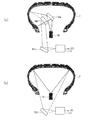
- FIGS. 2A and 2B illustrate an example of the measuring device 12 that measures the inner surface of the tire T.
- the inner surface of the tire T refers to the surface facing the tire cavity area surrounded by the tire T and the rim mounted thereon, and generally refers to the surface on which the inner liner is provided.
- the measuring device 12 mainly includes a camera 14, a light source 16, and mirrors 18a to 18d.
- a light cutting method is used.
- the surface shape of the inner surface of the tire T is measured by irradiating slit light from the light source 16 to the inner surface of the tire T and imaging the slit light of the inner surface of the tire T with the camera 14 inclined to a predetermined angle. Do.
- measurement data of the entire circumference of the inner surface of the tire T can be obtained by rotating the tire T around the tire rotation axis in the tire circumferential direction and continuously measuring the surface shape of the inner surface of the tire T.
- FIG. 2A is a view showing an example in which the inner surface corresponding to the sidewall portion of the inner surface of the tire T is measured.
- the slit light emitted from the light source 16 is changed in the direction of light by the mirror 18a, and the slit light is emitted to the inner surface corresponding to the sidewall portion.
- the image of the slit light emitted to the inner surface is imaged by the camera 14 via the mirrors 18 b and 18 c.
- the optical paths of the mirror 18b and the slit light are mutually offset in the tire circumferential direction so that the mirror 18b is not located in the optical path of the slit light.
- FIG. 2 (b) is a view showing an example of measuring the inner surface corresponding to the tread portion of the inner surface of the tire T.
- the slit light emitted from the light source 16 is applied to the inner surface corresponding to the tread portion.
- the image of the irradiated slit light is captured by the camera 14 via the mirror 18 d.
- the positions of the light source 16 and the mirror 18 d are mutually offset in the tire circumferential direction so that the light source 16 does not enter the imaging field of view of the camera 14. Measurement data obtained by measurement is sent to the defect inspection apparatus 20.
- the following dimensions are set as an example.
- the resolution of the image in the tire width direction and the tire circumferential direction so that the shape of the defect is reflected in the image.
- the resolution in the concavo-convex direction is determined by the resolution of the camera 14 and the angle between the camera 14 and the slit light, and is set to, for example, about 0.02 mm.
- the entire inner circumference of the tire T is measured, about 20000 in the tire circumferential direction and about 1500 pixels in the tire width direction for each of portions A to C (see FIG. 3) described later. An image of is obtained.
- the defect inspection apparatus 20 is an apparatus that determines the presence or absence of a defect in the tire by the discriminator identifying an image of a defect or a non-defective image in an inspection image of the tire.
- the defect inspection apparatus 20 includes a processing device 20 a which is a computer having a CPU 22, a GPU (Graphics Processing Unit) 23, and a memory 24, and a processing device 20 b which is a computer having a CPU 26 and a memory 28.
- the processing device 20a has a function of causing the discriminator 38 to learn an image of a defect or a non-defect image to be described later, and the processing device 20b reproduces the discriminator 38 that has learned the image of the defect and the non-defect It has a function to inspect the presence or absence of a defect of a tire from an inspection image of a tire.
- the processing device 20a is connected to a display 40 and an input operation system 44 such as a mouse / keyboard.
- the processing device 20 b is connected to a display 42 and an input operation system 46 such as a mouse / keyboard.
- the memory 24 and the memory 28 store a plurality of programs.
- the computer calls one of the programs from the memory 24 and activates it to form the image acquisition unit 30, the first processing unit 32, and the identifier 38, thereby configuring the processing device 20a.
- the computer calls up one of the programs from the memory 28 and starts up, thereby forming the second processing unit 34, the third processing unit 36, and the identifier 38 to configure the processing device 20b.
- the discriminator 38 formed by the processing device 20b reproduces the discriminator which has learned the image of the defect and the non-defective image by the processing device 20a. That is, the image acquisition unit 30, the first processing unit 32, the second processing unit 34, the third processing unit 36, and the discriminator 38 are modules formed by a program, and the functions of these parts are substantially the CPU 22. , 26 and the GPU 23.
- the defect inspection apparatus 20 is configured of two computers, the defect inspection apparatus 20 may be configured using one computer. Further, according to one embodiment, a part of the image acquisition unit 30, the first processing unit 32, the second processing unit 34, the third processing unit 36, and the identifier 38 may be hardware, for example, an application specific integrated (ASIC) Integrated circuit such as Circuit).
- ASIC application specific integrated
- the discriminator 38 is a part that discriminates an image of a defect or a non-defect image in the image using the image provided from the second processing unit 34, and a known machine learning method is used. The learning of the image of the defect and the non-defect is performed using the image for learning provided from the first processing unit 32 and the information of the result of the presence or absence of the image of the defect in the image for learning.
- the discriminator 38 is, for example, a unit that learns an image of defects and non-defects using a neural network. As the discriminator 38, for example, a convolutional neural network widely used in image recognition is suitably used.
- the image acquisition unit 30 acquires a defect image including an image of a defect of the tire different from the tire to be inspected and a defect-free image without the image of the defect for the learning of the classifier 38. Specifically, the image acquisition unit 30 generates an image of the inner surface of the tire T using measurement data of the tire T obtained by the measurement of the measurement device 12.
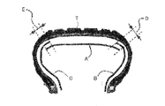
- FIG. 3 is a view for explaining an example of a portion to be measured on the inner surface of the tire T. As shown in FIG. 3, the inner surface of the tire T is divided into a portion A corresponding to the tread portion and portions B and C corresponding to sidewalls. In the measurement of the inner surface of the tire T, it is measured so that the part A and the part D and E which a part overlaps with the part B or the part C may be made.
- the image acquired by the image acquiring unit 30 is represented by an XY orthogonal coordinate system in which the tire width direction along the inner surface of the tire T is the x direction and the tire circumferential direction is the y direction. It is the image which represented the value of the unevenness
- the image acquisition unit 30 performs filter processing on the acquired image. Since the generated image includes a curved component (curved component) of the inner surface of the tire T, it is preferable to remove the curved component from the image in advance. Since the discriminator 38 learns the image of the defect which is a minute uneven shape on the inner surface of the tire T and the image of the non defect which is not the defect to discriminate the image of the defect in the supplied inspection image, However, it is not preferable in terms of the accuracy of identification of an image of a defect having a concavo-convex shape that it is included in the learning image and inspection image. For this reason, the image acquisition unit 30 performs filter processing on the image to remove the bending component.
- the image acquisition unit 30 performs filter processing on the image to remove the bending component.
- a median filter and an average filter are applied to the image to extract an image of a curved component, and the pixel value of this image is subtracted from the pixel value of the image before filter processing.
- the filter processing for removing the curved component is not necessarily essential in identifying the image of the defect, but it is possible to use the image subjected to the filter processing as a learning image or as an inspection image for inspection of the image of the defect. It is preferable from the point of performing a defect inspection with high accuracy.
- the image acquisition unit 30 acquires a defect image including an image of a defect and a defect-free image without a defect image of a tire other than the tire to be inspected, for learning of the classifier 38.
- Examples of such images are shown in FIGS.
- FIGS. 4 (a) to 4 (c) show examples of images without a defect image
- FIGS. 5 (a) to 5 (c) are pseudo images similar to the defect image but not classified as a defect image
- FIGS. 6A to 6C are views showing an example of an image having an image of a defect
- FIGS. 6A to 6C are diagrams showing an example of an image having an image of a defect.
- Such an image is generated as a cutout defect image serving as a learning image as described later or a cutout inspection image for inspecting an image of the defect by the discriminator 38.
- the first processing unit 32 of the processing unit 20a and the second processing unit 34 and the third processing unit 36 of the processing unit 20b prepare images for learning and identification of defect and non-defect images by the discriminator 38. Or, it is a part which gathers the identification result of the image of a defect.
- FIG. 7 is a view for explaining a defect inspection method according to an embodiment which the defect inspection apparatus 20 performs.
- the defect inspection method of the embodiment shown in FIG. 7 will be described while explaining the functions of the first processing unit 32, the second processing unit 34, the third processing unit 36, and the identifier 38.
- the image acquisition unit 30 uses the above-described filtering process to learn the discriminator 38.
- the image of the tire other than the tire to be inspected has no defect image and no defect image of the defect including the image of the defect.
- An image is acquired (step ST10).
- the first processing unit 32 causes the discriminator 38 to learn an image of a defect and an image of a non-defect that is not a defect using the acquired defect image and the non-defective image (step ST12).
- the first processing unit 32 identifies a plurality of cutout defect images created by changing the cutout region cut out from the defect image so that the image of the defect in the defect image is at a different position in the image. It provides the device 38 as a learning image.
- the provided learning image is, for example, a gray scale image of 256 gradation values with 256 ⁇ 256 pixel numbers.
- the first processing unit 32 changes the cutout area so that the image of the defect in the defect image is at a different position in the image, and creates a plurality of cutout defect images from the defect image because the image of the defect is This is to prevent the discriminator 38 from learning that the disc is at a predetermined position in the image.
- the probability of occurrence of defects is low and the total number of defect images is small, the number can be made closer to the number of cutout non-defective images created from defect-free images by increasing the total number of cutout defect images used as learning images. Enable accurate identification of defect images.
- the cutout defect image has one image whose position in the image of the defect (the center position of the image of the defect) is at the center pixel position of the cutout defect image and the center pixel of the cutout defect image It is preferable to include a plurality of images located at predetermined distances and positions separated in the vertical and horizontal directions with respect to the position. According to one embodiment, it is preferable to set a distance that is an integral multiple of the reference distance represented by the number of pixels as the predetermined distance. For example, distances of 1 times, 2 times, 3 times,..., 8 times the reference distance corresponding to the number of pixels are set as the predetermined distances.
- the total number of integers used for integral multiples of the reference distance is referred to as the number of slides, and in the case of 1 ⁇ , 2 ⁇ , 3 ⁇ ,..., 8 ⁇ , the number of slides is 8. Therefore, in a plurality of cutout defect images, images of the same defect exist at a plurality of positions. For example, when the number of slides is 8, the image of the same defect moves to 16 locations in the left and right directions except for the center pixel position of the cutout defect image, and further, excluding the center pixel position of the cutout defect image in the vertical direction Since the image of the same defect moves to 16 locations, a total of 17 ⁇ 17 cutout defect images are generated from one defect image.
- FIG. 8A shows an example in which the cutout area 54 is arranged such that the image 52 of the defect (the center of the image 52 of the defect) in the defect image 50 is at the center pixel position of the cutout defect image.
- 8 (b) and 8 (c) compared with the cutout area 54 shown in FIG. 8 (a) so that the image 52 of the defect (the center of the image 52 of the defect) is at the lower right position of the cutout defect image.
- An example is shown in which the cutout area 54a is moved to the upper left side. Therefore, in the plurality of cutout defect images, as shown in FIG. 8D, the position of the defect image 52 is moved out in the vertical direction and the horizontal direction from the center pixel position of the cutout defect image 54 Defect images can be created.
- the image of this defect is 1 times, 2 times, 3 times,..., 8 times the reference distance equivalent to 5 pixels.
- the image of this defect is 1 times, 2 times, 3 times,..., 8 times the reference distance equivalent to 5 pixels.
- the classifier 38 learns the images of defects and non-defects using the cutout defect image and the cutout non-defective image provided to the classifier 38 and the information about the presence or absence of defects.
- the learning information of the discriminator 38 learned in the processing device 20a is transferred to the processing device 20b, and the discriminator 38 in the processing device 20b is reproduced as a machine-learned discriminator.
- the second processing unit 34 provides the cutout inspection image, and the discriminator 38 identifies the presence or absence of an image of a defect in the cutout inspection image (step ST14).
- the second processing unit 34 generates a cutout inspection image from the acquired inspection image.
- the cutout inspection image is an image cut out by changing the cutout region without leaking all the regions of the inspection image covering the entire inner surface of the tire.
- the inspection image is an image obtained by measuring the inner surface of the tire T to be inspected by the image acquisition unit 30.
- the second processing unit 34 causes the cutout region in each of the cutout inspection images to partially overlap with the cutout region in at least one of the cutout inspection images in the inspection image.
- a cutout inspection image is generated. Thereby, the image of the defect in the inspection image can be inspected without omission.
- FIG. 9 is a diagram for explaining the relationship between an examination image and a cutout examination image in one embodiment. As shown in FIG. 9, the cutout region 62 for generating each of the inspection images from the inspection image 60 partially overlaps the cutout regions 62a and 62b in at least one of the cutout inspection images in the inspection image 60. ing.
- the image sizes of the cutout defect image generated by the first processing unit 32 and the cutout inspection image generated by the second processing unit 34 are the same, and the cutout inspection image is the same.
- the cutout region 62 in each of the regions is a region moved by a predetermined distance in the vertical direction or the horizontal direction with respect to the cutout regions 62a and 62b in at least one of the cutout inspection images.
- the movement distance of the cutout region 62 in the cutout inspection image is the fluctuation of the farthest position of the image 52 of the defect in the cutout defect image in any of the cutout defect image and the cutout inspection image in the vertical and horizontal directions.
- the image of the defect at any position of the inspection image falls within the corresponding range of the cutout inspection image corresponding to the moving range of the position of the image of the defect in the cutout defect image. It can be done well.
- the movement distance of the cutout region 62 in the cutout inspection image generated by the second processing unit 34 is a predetermined distance (a distance that is an integral multiple of the reference distance) in the cutout defect image generated by the first processing unit 32 Is preferably greater than Since the predetermined distance is at a maximum eight times the reference distance in the above-described example, it is preferable that the moving distance of the cutout region 62 be greater than eight times the reference distance. Thereby, since the number of cutout inspection images can be suppressed, the time for inspection of defects can be shortened.
- the third processing unit 36 determines the presence or absence of a defect in the inner surface of the tire T to be inspected using the discrimination result of the presence or absence of the image of the defect in the cutout inspection image in the processing device 20b (step ST16) . Since the cutout inspection image used to identify the presence or absence of the image of the defect partially overlaps other cutout inspection images in the inspection image 60, the third processing unit 36 Count the number of If there is even one defect on the entire inner circumference of the tire T, the tire T is determined to be defective. The inspection results (the presence or absence of defects and the number of defects) of such defects are sent to the display 42 and displayed on the display 42. Information on the location of the defect is also displayed as needed. In addition, the third processing unit 36 integrates the cutout inspection image into the image of the entire inner circumference of the tire T. The area of the cropped inspection image identified as having a defect image in the integrated image is framed and displayed on the display 42.
- the defect inspection apparatus 20 extracts the cutout area 54 so that the image of the defect in the defect image from the defect image comes to different positions in the image.
- a plurality of cut-out defect images created by changing are provided to the classifier 38 as learning images. This makes it possible to efficiently identify the images of various defects regardless of where in the inspection image the image of the defect is located.
- the test object was made into the inner surface of the tire T
- the surface of the outer side of tire T such as a sidewall and a tread part, can also be made into a test object.
- an image in which the discrimination result by the discriminator 38 and the standard compliance judgment result judged from the predetermined inspection standard is a standard compliance judgment
- the results are preferably provided to the discriminator 38 for learning of the discriminator 38 as a learning image.
- the classifier 38 By causing the classifier 38 to learn such learning, it is possible to increase the accuracy of identification of the image of the defect.
- the size of the image of the defect to be inspected is various. Thus, according to one embodiment, it is preferable to scale the image according to the size of the image of the defect in the defect image.
- the size of the cutout region change the resolution
- the size of the cutout area 54 and the number of pixels of the cutout defect image are changed through the input operation system 28.
- the surface unevenness of the background pattern in the inner liner rubber, the vulcanization process is formed on the inner surface of the tire T.
- the unevenness pattern of the bladder that presses the inner surface of the green tire from the inside there are unevenness shapes that are not identified as defects, and those that have characteristics equivalent to defects but do not correspond to defects because their dimensions are below the standard. That is, although not classified as a defect, there exist pseudo defects having an uneven shape.
- the false defect is preferably configured not to be identified as an image of the defect in the identifier 38.
- the learning image used to learn the images of defects and non-defects provided to the discriminator 38 has an image of defects and an image of false defects and an image of false defects but no image of defects.
- An image is included as a cutout non-defective image, and an image with an image of a defect is included as a cutout defect image.
- FIG. 10 is a diagram for explaining the configuration of the discriminator 38 according to an embodiment.
- the discriminator 38 is a discriminator unit configured of a first discriminator 38a and a second discriminator 38b, and discriminates between the first discriminator 38a and the second discriminator 38b. Differentiate the target.
- the first discriminator 38a discriminates that there is an image of a defect candidate or no image of a defect candidate in the cutout inspection image.
- the image of the defect candidate includes the image of the pseudo defect.
- the second discriminator 38b has an image of a pseudo defect similar to the image of the defect but not classified as the image of the defect in the cutout inspection image identified as having the image of the defect candidate by the first classifier 38a, Alternatively, it is determined whether there is an image of a defect.
- the first processing unit 32 uses an image including an image of a defect candidate and an image including no image of a defect candidate as learning images for learning the first discriminator 38a. It provides the first identifier 38a.
- the image of the defect candidate includes the image of the pseudo defect in addition to the image of the defect.
- the first discriminator 38a treats the discrimination result other than the discrimination result of no image of defect candidate by the first discriminator 38a as the image of defect candidate.
- the first processing unit 32 uses an image including an image of a pseudo defect and an image including an image of a defect as a learning image for learning the second classifier 38 b.
- the learned second identifier 38b identifies the image of the defect candidate identified by the first learner 38a into an image of the defect and an image of the false defect.
- the defect inspection apparatus 20 performs inspection by the conventional inspector. The same inspection can be done.
- a learning image with a pseudo defect image but no defect image, a learning image with neither a pseudo defect image nor a defect image, a learning image with a defect image, the number of slides is set to generate an image
- the prepared learning image has a pseudo defect image but no defect image
- the detection rate 1 is a detection rate of the single-stage system by the detector 38.
- the prepared learning image has neither a false defect image nor a defect image, a learning image without a defect candidate, a false defect image but no defect image, a learning image and a defect image for learning
- a first discriminator 38a was created in which the image was learned as having a defect candidate (see FIG. 10).
- a second discriminator 38b was created in which a learning image with a false defect image but no defect image is learned as no defect and a learning image with a defect image as a defect (see FIG. 10).
- the inspection image including the defect image created separately from the learning image is provided to the first discriminator 38a and the second discriminator 38b, and is obtained from the discrimination result by the first discriminator 38a and the second discriminator 38b.
- the detection rate of the image of the defect was determined as the detection rate 2.
- the detection rate 2 is a detection rate of the two-stage system by the first detector 38a and the second detector 38b. Although the detection rate 1 is high, the detection rate 2 is increased by 14% more than the detection rate 1.
- the detection rate is the ratio of the number of inspection images correctly detected as defects to the total number of inspection images to be detected originally as defects.
- images of defects not limited to a specific type can be efficiently identified using the identifier 38 or using the first identifier 38a and the second identifier 38b.
- the method of the present embodiment is effective in the inspection of a defect of an article having a large shape variation element such as a tire.
- an image of a defect and an image of a pseudo defect can also be identified.
- the false recognition rate of the image of the defect can be reduced.
- the embodiments described above are thus suitable for the automation of the inspection of defects in articles comprising tires.
- the present invention is not limited to the above-mentioned embodiment and an example, and performs various improvement and change in the range which does not deviate from the main point of the present invention. Of course it is good.
Abstract
To cause a discriminator to learn when inspecting defects in an article, a defect image containing a defect and a non-defect image with no defect are acquired, the defect image and the non-defect image being images of an article different from the article being inspected, and the discriminator is caused to learn an image of a defect and an image of a non-defect which is not the defect, using the defect image and the non-defect image. The learned discriminator is caused to discriminate between whether or not each cut-out inspection image obtained by classifying an inspection image of the article being inspected contains a defect, and the presence or absence of the defect in the article being inspected is determined using the discrimination result obtained by the discriminator. When the discriminator is being caused to learn the defect, the discriminator is provided, as images for learning, with a plurality of cut-out defect images created from the defect image by modifying a cut-out region cut out from the defect image in such a way that the defect in the defect image is in a different position in each image.
Description
本発明は、物品の、検査画像における欠陥の像を識別器が識別することにより、物品の欠陥を検査する欠陥検査方法及び欠陥検査装置に関する。
The present invention relates to a defect inspection method and a defect inspection apparatus for inspecting a defect of an article by a discriminator identifying an image of a defect in an inspection image of the article.
従来より、製造されたタイヤ全数に対して、タイヤの外面と内面を検査員が手で触りあるいは目視により欠陥の有無を判断する検査が行われている。この検査では、タイヤ部位と発生要因毎に欠陥の規定寸法を定義して欠陥の有無の判定が行われる。欠陥の定量化ができないものは限度見本を作り、限度見本との比較により欠陥の有無が判定される。検査員が、欠陥がなく合格品と判定するタイヤの中には、欠陥に類似するが、規定寸法を満たさない等の理由から欠陥とは判断されない「擬似欠陥」が含まれる。
Heretofore, with respect to all the manufactured tires, an inspection has been performed by an inspector touching the outer surface and the inner surface of the tire with a hand or judging visually whether there is a defect. In this inspection, a defined size of a defect is defined for each tire portion and occurrence factor to determine the presence or absence of a defect. Those incapable of quantifying defects make a limit sample, and comparison with the limit sample determines the presence or absence of a defect. Tires that an inspector determines that they have no defect and are acceptable products include “pseudo defects” that are similar to defects but are not determined to be defects because they do not satisfy prescribed dimensions.
近年、検査員による検査負担の軽減のために、タイヤ外面や内面の全範囲の撮像及び欠陥の像の識別を自動化することが望まれている。
例えば、タイヤ外面のトレッド(タイヤ接地面)表面上に発生する厚さ0.4mm、面積100mm2程度を有する凸型楕円形状の薄広面状欠陥の有無判定を行うために、画像処理によるトレッドパターンと呼ばれるタイヤ溝部を除去した外面特徴抽出手法が提案されている(非特許文献1)。
また、タイヤ内面を対象とし、LED照明とエリアカメラを撮像手段として用い、照明環境と画像処理システムをそれぞれ工夫することによって、タイヤ内面に存在する周期的パターンの模様を認識して除外し、欠陥を検出する手法が提案されている(非特許文献2)。 In recent years, in order to reduce the inspection burden on inspectors, it is desired to automate the imaging of the entire range of the outer surface and the inner surface of the tire and the identification of the image of the defect.
For example, in order to determine the presence or absence of a thin oval surface defect having a thickness of about 0.4 mm and an area of about 100 mm 2 generated on the tread (tire contact surface) surface of the tire outer surface, a tread pattern by image processing An outer surface feature extraction method has been proposed in which the tire groove portion called as has been removed (Non-Patent Document 1).
In addition, by targeting the inner surface of the tire, using LED illumination and an area camera as imaging means, and devising the illumination environment and the image processing system respectively, the pattern of the periodic pattern existing on the inner surface of the tire is recognized and excluded. A method for detecting H. has been proposed (Non-Patent Document 2).
上述の欠陥の判定では、画像中の背景模様や特定の種類の欠陥に応じて一品一様に対応させた欠陥識別アルゴリズムを作成して、特定の種類の欠陥を精度よく識別することはできるが、検査員が行うように種々の欠陥を効率よく識別することは難しい。さらには、擬似欠陥を識別することも難しい。
特定の種類の欠陥を対象とせず、種々の欠陥の識別を行うことは、タイヤに限られず、一般の物品の検査工程においても重要である。 In the above-mentioned defect determination, it is possible to create a defect identification algorithm corresponding to one item uniformly according to the background pattern in the image or a specific type of defect, and to identify the specific type of defect with high accuracy. It is difficult to efficiently identify various defects as inspectors do. Furthermore, it is also difficult to identify false defects.
Identification of various defects without targeting specific types of defects is important not only in tires but also in the inspection process of general articles.
そこで、本発明は、従来のように、物品の表面に形成された特定の種類の欠陥を識別するのではなく、種々の欠陥を効率よく識別することができる物品の欠陥検査方法及び欠陥検査装置を提供することを目的とする。
Therefore, the present invention does not identify a specific type of defect formed on the surface of an article as in the prior art, and an article defect inspection method and an defect inspection apparatus capable of efficiently identifying various defects. Intended to provide.
本発明の一態様は、物品の、検査画像における欠陥の像を識別器が識別することにより、物品の欠陥を検査する欠陥検査方法である。当該欠陥検査方法は、
識別器の学習のために、検査対象物品とは別の物品の、欠陥の像を含んだ欠陥画像及び欠陥の像の無い無欠陥画像を取得するステップと、
前記欠陥画像及び前記無欠陥画像を用いて前記識別器に前記欠陥の像及び前記欠陥ではない非欠陥の像を学習させるステップと、
学習した前記識別器に、前記検査対象物品の検査画像を区分けした切り出し検査画像それぞれが欠陥の像を含むか否かを識別させるステップと、
前記識別器の識別結果を用いて、前記検査対象物品の欠陥の有無を判定するステップと、を備える。
前記識別器に前記欠陥の像及び前記非欠陥の像を学習させるとき、前記欠陥画像中の前記欠陥の像が画像中の異なる位置に来るように、前記欠陥画像から切り出す欠陥切り出し領域を変更して前記欠陥画像から作成した複数の切り出し欠陥画像を、前記識別器に学習用画像として提供する。 One aspect of the present invention is a defect inspection method for inspecting a defect of an article by a discriminator identifying an image of a defect in an inspection image of the article. The defect inspection method is
Acquiring a defect image including an image of a defect and a defect-free image without a defect image of an item other than the item to be inspected, for learning of the classifier;
Making the classifier learn the image of the defect and the non-defective image that is not the defect using the defect image and the defect-free image;
Making each of the learned classifiers discriminate whether or not each cutout inspection image obtained by dividing the inspection image of the inspection object contains an image of a defect;
Determining the presence or absence of a defect of the inspection object using the identification result of the identifier.
When the discriminator learns the image of the defect and the image of the nondefect, the defect cutout area cut out from the defect image is changed so that the image of the defect in the defect image comes to different positions in the image. A plurality of cutout defect images created from the defect image are provided to the classifier as learning images.
前記切り出し欠陥画像は、前記欠陥の像の画像内の位置が、前記切り出し欠陥画像の中心画素位置にある1つの画像と、前記切り出し欠陥画像の中心画素位置に対して、所定の距離、上下方向及び左右方向に離れた位置にある複数の画像と、を含む、ことが好ましい。
The cutout defect image has a predetermined distance in the vertical direction with respect to the center pixel position of the cutout defect image and one image in which the position in the image of the image of the defect is at the center pixel position of the cutout defect image. And a plurality of images located at positions separated in the left-right direction.
前記切り出し検査画像は、前記検査画像の全ての領域が漏れることなく切り出し領域を変えて切り出した画像であり、
前記切り出し検査画像のそれぞれにおける前記切り出し領域は、前記切り出し検査画像の少なくとも1つにおける前記切り出し領域と重なっている、ことが好ましい。 The cutout inspection image is an image cut out by changing the cutout region without leaking all the regions of the inspection image,
The cutout area in each of the cutout inspection images preferably overlaps with the cutout area in at least one of the cutout inspection images.
前記切り出し欠陥画像と前記切り出し検査画像の画像サイズは同じであり、
前記切り出し検査画像のそれぞれにおける前記切り出し領域は、前記切り出し検査画像の少なくとも1つにおける前記切り出し領域に対して上下方向あるいは左右方向に所定の距離、移動した領域であり、
前記切り出し検査画像における前記切り出し領域の移動距離は、前記切り出し欠陥画像及び前記切り出し検査画像の上下方向及び左右方向のいずれにおいても、前記切り出し欠陥画像における前記欠陥の像の互いに最も遠く離れた位置の変動量と同じかそれ以下である、ことが好ましい。 The image sizes of the cutout defect image and the cutout inspection image are the same,
The cutout area in each of the cutout inspection images is an area moved by a predetermined distance in the vertical direction or in the horizontal direction with respect to the cutout area in at least one of the cutout inspection images,
The movement distance of the cutout region in the cutout inspection image is the farthest distance between the images of the defects in the cutout defect image in any of the vertical direction and the horizontal direction of the cutout defect image and the cutout inspection image Preferably, it is equal to or less than the fluctuation amount.
前記切り出し欠陥画像は、前記欠陥の像の画像内の位置が、前記切り出し欠陥画像の中心画素位置にある1つの画像と、前記切り出し欠陥画像の中心画素位置に対して、所定の距離の整数倍、上下方向及び左右方向に離れた位置にある複数の画像と、を含み、
前記整数倍における整数と、前記所定の距離と、を調整することにより、前記切り出し欠陥画像の総数を調整する、ことが好ましい。 The cutout defect image is an integral multiple of a predetermined distance with respect to the center pixel position of the cutout defect image and one image in which the position in the image of the defect image is at the center pixel position of the cutout defect image. , And a plurality of images at positions separated in the vertical direction and the horizontal direction,
It is preferable that the total number of the cutout defect images be adjusted by adjusting the integer at the integer multiple and the predetermined distance.
前記切り出し欠陥画像は、前記欠陥の像の画像内の位置が、前記切り出し欠陥画像の中心画素位置にある1つの画像と、前記切り出し欠陥画像の中心画素位置に対して、所定の距離の整数倍、上下方向及び左右方向に離れた位置にある複数の画像と、を含み、
前記切り出し検査画像における前記切り出し領域の前記移動距離は、前記切り出し欠陥画像における前記所定の距離より大きい、ことが好ましい。 The cutout defect image is an integral multiple of a predetermined distance with respect to the center pixel position of the cutout defect image and one image in which the position in the image of the defect image is at the center pixel position of the cutout defect image. , And a plurality of images at positions separated in the vertical direction and the horizontal direction,
It is preferable that the movement distance of the cutout area in the cutout inspection image is larger than the predetermined distance in the cutout defect image.
前記識別器に前記欠陥の像及び前記非欠陥の像を学習させる前記学習用画像は、前記切り出し欠陥画像の他に、欠陥の像の無い、前記切り出し欠陥画像の画像サイズと同じ大きさの複数の無欠陥画像を含み、
前記切り出し検査画像のうち、前記識別器による識別結果と、予め定めた検査規格から判断される規格準拠判断結果とが異なる画像は、前記規格準拠判断結果とともに、前記学習用画像として前記識別器の学習のために、前記識別器に提供される、ことが好ましい。 The learning image for causing the discriminator to learn the image of the defect and the image of the non-defective is a plurality of images having the same size as the image size of the cutout defect image without the image of the defect in addition to the cutout defect image. Containing no defect images of
Among the cut out inspection images, an image having a discrimination result by the classifier and a standard compliance judgment result judged from a predetermined inspection standard, is different from the classifier inspection image as the learning image together with the standard compliance judgment result. Preferably, it is provided to the identifier for learning.
前記欠陥画像内の欠陥の像の大きさに応じて、前記切り出し欠陥画像の画素数を変更せずに前記切り出し領域の大きさを調整する、あるいは、前記切り出し欠陥画像の画素数を変更して前記切り出し領域の大きさを調整する、ことが好ましい。
According to the size of the image of the defect in the defect image, adjust the size of the cutout region without changing the number of pixels of the cutout defect image, or change the number of pixels of the cutout defect image Preferably, the size of the cutout region is adjusted.
本発明の他の一態様は、物品の、検査画像における欠陥の像を識別器ユニットが識別することにより、物品の欠陥を検査する欠陥検査方法である。当該欠陥検査方法は、
前記識別器ユニットの学習のために、検査対象物品とは別の物品の、欠陥の像を含んだ欠陥画像及び欠陥の像の無い無欠陥画像を取得するステップと、
前記欠陥画像及び前記無欠陥画像を用いて前記識別器ユニットに前記欠陥の像を学習させるステップと、
学習した前記識別器ユニットに、前記検査対象物品の検査画像を区分けした切り出し検査画像それぞれが欠陥の像を含むか否かを識別させるステップと、
前記識別器ユニットの識別結果を用いて、前記検査対象物品の欠陥の有無を判定するステップと、を備え、
前記識別器ユニットは、前記切り出し検査画像内に、欠陥の可能性がある欠陥候補の像有り、あるいは、欠陥候補の像無し、の識別をする第1識別器と、前記第1識別器により、欠陥候補の像有りと識別された切り出し検査画像内に、欠陥の像に類似するが欠陥の像として分類されない擬似欠陥の像が有るか、あるいは、欠陥の像が有るか、を識別する第2識別器とを備え、前記欠陥候補は、前記欠陥及び、前記擬似欠陥を含み、
前記第1識別器を学習させるための学習用画像は、欠陥候補の像を含む画像と、前記欠陥候補の像を含まない画像とを含み、
前記第2識別器を学習させるための学習用画像は、擬似欠陥の像を含む画像と、欠陥の像を含む画像とを含む。 Another aspect of the present invention is a defect inspection method for inspecting a defect in an article by a discriminator unit identifying an image of a defect in an inspection image of the article. The defect inspection method is
Acquiring a defect image including an image of a defect and a defect-free image without a defect image of an item other than the item to be inspected for learning of the identifier unit;
Allowing the discriminator unit to learn an image of the defect using the defect image and the defect-free image;
Allowing the learned classifier unit to identify whether each cutout inspection image obtained by dividing the inspection image of the inspection object includes an image of a defect;
Determining the presence or absence of a defect of the inspection object using the identification result of the identifier unit;
The discriminator unit comprises: a first discriminator for discriminating the presence of an image of a defect candidate having a possibility of a defect or no image of a defect candidate in the cutout inspection image; and the first discriminator Second, it is determined whether or not there is an image of a pseudo defect similar to the image of the defect but not classified as an image of the defect in the cutout inspection image identified as having the image of the defect candidate, or the image of the defect A discriminator, the defect candidate includes the defect and the pseudo defect;
The training image for training the first discriminator includes an image including an image of a defect candidate and an image not including an image of the defect candidate,
The training image for training the second identifier includes an image including an image of a pseudo defect and an image including an image of a defect.
発明のさらに他の一態様は、物品の、検査画像における欠陥の像を識別器が識別することにより、物品の欠陥を検査する欠陥検査装置である。当該欠陥検査装置は、
提供された画像を用いて前記画像内の欠陥の像を識別する識別器と、
前記識別器の学習のために、検査対象物品とは別の物品の欠陥の像を含んだ欠陥画像及び欠陥の像の無い無欠陥画像を取得する画像取得部と、
前記欠陥画像及び前記無欠陥画像を用いて前記識別器に前記欠陥の像及び前記欠陥ではない非欠陥の像を学習させる第1処理部と、
学習した前記識別器に、前記検査対象物品の検査画像を区分けした切り出し検査画像それぞれから、前記切り出し検査画像が欠陥の像を含むか否かを識別させる第2処理部と、
前記識別器の識別結果を用いて、前記検査対象物品の欠陥の有無を判定する第3処理部と、を備える。
前記第1処理部は、前記欠陥画像中の前記欠陥の像が画像中の異なる位置に来るように、前記欠陥画像から切り出す切り出し領域を変更して前記欠陥画像から作成した複数の切り出し欠陥画像を、前記識別器に学習用画像として提供する。 Yet another aspect of the invention is a defect inspection apparatus that inspects a defect in an article by an identifier identifying an image of a defect in an inspection image of the article. The defect inspection device
A classifier for identifying an image of a defect in the image using the provided image;
An image acquisition unit for acquiring a defect image including an image of a defect of an article different from the inspection object and a non-defective image having no image of the defect for learning of the classifier;
A first processing unit that causes the discriminator to learn the image of the defect and the non-defective image that is not the defect using the defect image and the defect-free image;
A second processing unit that causes the learned classifier to identify whether the cutout inspection image includes an image of a defect from each of the cutout inspection images obtained by dividing the inspection image of the inspection object;
And a third processing unit that determines the presence or absence of a defect of the inspection object using the identification result of the identifier.
The first processing unit changes a cutout region cut out from the defect image so that the image of the defect in the defect image is at a different position in the image, and generates a plurality of cutout defect images created from the defect image And providing the discriminator as a learning image.
発明のさらに他の一態様は、物品の、検査画像における欠陥の像を識別器が識別することにより、物品の欠陥を検査する欠陥検査装置である。当該欠陥検査装置は、
提供された画像を用いて前記画像内の欠陥の像を識別する識別器ユニットと、
前記識別器ユニットの学習のために、検査対象物品とは別の物品の欠陥の像を含んだ欠陥画像及び欠陥の像の無い無欠陥画像を取得する画像取得部と、
前記欠陥画像及び前記無欠陥画像を用いて前記識別器ユニットに前記欠陥の像を学習させる第1処理部と、
学習した前記識別器ユニットに、前記検査対象物品の検査画像から区分けした切り出し検査画像それぞれから、前記切り出し検査画像が欠陥の像を含むか否かを識別させる第2処理部と、
前記識別器の識別結果を用いて、前記検査対象物品の欠陥の有無を判定する第3処理部と、を備える。
前記識別器ユニットは、少なくとも第1識別器と第2識別器を含み、
前記第1識別器は、前記切り出し検査画像内に、欠陥の可能性がある欠陥候補の像有り、あるいは、欠陥候補の像無しの識別をし、
前記第2識別器は、前記第1識別器により、欠陥候補の像有りと識別された切り出し検査画像内に、欠陥の像に類似するが欠陥の像として分類されない擬似欠陥の像が有るか、あるいは、欠陥の像が有るか、を識別し、前記欠陥候補は、前記欠陥及び、前記擬似欠陥を含み、
前記第1識別器を学習させるための学習用画像は、欠陥候補の像を含む画像と、欠陥候補の像を含まない画像とを含み、
前記第2識別器を学習させるための学習用画像は、擬似欠陥の像を含む画像と、欠陥の像を含む画像とを含む。 Yet another aspect of the invention is a defect inspection apparatus that inspects a defect in an article by an identifier identifying an image of a defect in an inspection image of the article. The defect inspection device
A classifier unit for identifying an image of a defect in the image using the provided image;
An image acquisition unit for acquiring a defect image including an image of a defect of an article different from the inspection object and a non-defective image having no image of the defect for learning of the classifier unit;
A first processing unit that causes the discriminator unit to learn an image of the defect using the defect image and the defect-free image;
A second processing unit that causes the learned classifier unit to identify whether or not the cutout inspection image includes an image of a defect from each of the cutout inspection images divided from the inspection image of the inspection target article;
And a third processing unit that determines the presence or absence of a defect of the inspection object using the identification result of the identifier.
The identifier unit includes at least a first identifier and a second identifier,
The first discriminator discriminates in the cutout inspection image that there is an image of a defect candidate that has a possibility of a defect or no image of a defect candidate.
The second discriminator determines whether there is an image of a pseudo defect similar to the image of the defect but not classified as the image of the defect in the cutout inspection image in which the image of the defect candidate is identified by the first classifier. Alternatively, it is identified whether there is an image of a defect, and the defect candidate includes the defect and the pseudo defect.
The training image for training the first discriminator includes an image including an image of a defect candidate and an image including no image of the defect candidate,
The training image for training the second identifier includes an image including an image of a pseudo defect and an image including an image of a defect.
上述の欠陥検査方法及び欠陥検査装置によれば、物品の種々の欠陥を効率よく識別することができる。
According to the above-described defect inspection method and defect inspection apparatus, various defects of an article can be efficiently identified.
以下、本発明の欠陥検査方法及び欠陥検査装置を詳細に説明する。図1は、一実施形態であるタイヤの欠陥を検査する欠陥検査システム10の構成を示すブロック図である。欠陥検査システム10では、タイヤを検査対象物品としているが、検査対象物品は、タイヤに限定されず、製造直後のいかなる物品であってもよい。
Hereinafter, the defect inspection method and defect inspection apparatus of the present invention will be described in detail. FIG. 1 is a block diagram showing a configuration of a defect inspection system 10 for inspecting a defect of a tire according to an embodiment. In the defect inspection system 10, the tire is an object to be inspected, but the object to be inspected is not limited to the tire, and may be any item immediately after production.
欠陥検査システム10は、計測装置12と、欠陥検査装置20と、を備える。計測装置12は、タイヤTの内面の形状を計測してデータを取得する。欠陥検査装置20は、取得したデータを用いて、タイヤTの検査画像から、タイヤTに欠陥があるか否かを判定する。
The defect inspection system 10 includes a measuring device 12 and a defect inspection device 20. The measuring device 12 measures the shape of the inner surface of the tire T to acquire data. The defect inspection apparatus 20 determines whether the tire T has a defect from the inspection image of the tire T using the acquired data.
図2(a),(b)は、タイヤTの内面の計測を行う計測装置12の一例を説明する図である。タイヤTの内面とは、タイヤTと装着されるリムによって囲まれるタイヤ空洞領域に面する面であり、一般的にインナーライナが設けられている面をいう。
FIGS. 2A and 2B illustrate an example of the measuring device 12 that measures the inner surface of the tire T. FIG. The inner surface of the tire T refers to the surface facing the tire cavity area surrounded by the tire T and the rim mounted thereon, and generally refers to the surface on which the inner liner is provided.
計測装置12は、カメラ14、光源16、及びミラ18a~18dを主に備える。
計測装置12では、例えば、光切断法が用いられる。光切断法は、光源16からタイヤTの内面にスリット光を照射し、所定の角度に傾けたカメラ14でタイヤTの内面のスリット光を撮像することで、タイヤTの内面の表面形状を計測する。さらに、タイヤTをタイヤ回転軸の回りにタイヤ周方向に回転させてタイヤTの内面の表面形状を連続的に計測することで、タイヤTの内面の全周の計測データを得る。 The measuringdevice 12 mainly includes a camera 14, a light source 16, and mirrors 18a to 18d.
In the measuringdevice 12, for example, a light cutting method is used. In the light cutting method, the surface shape of the inner surface of the tire T is measured by irradiating slit light from the light source 16 to the inner surface of the tire T and imaging the slit light of the inner surface of the tire T with the camera 14 inclined to a predetermined angle. Do. Furthermore, measurement data of the entire circumference of the inner surface of the tire T can be obtained by rotating the tire T around the tire rotation axis in the tire circumferential direction and continuously measuring the surface shape of the inner surface of the tire T.
計測装置12では、例えば、光切断法が用いられる。光切断法は、光源16からタイヤTの内面にスリット光を照射し、所定の角度に傾けたカメラ14でタイヤTの内面のスリット光を撮像することで、タイヤTの内面の表面形状を計測する。さらに、タイヤTをタイヤ回転軸の回りにタイヤ周方向に回転させてタイヤTの内面の表面形状を連続的に計測することで、タイヤTの内面の全周の計測データを得る。 The measuring
In the measuring
図2(a)は、タイヤTの内面のうち、サイドウォール部分に対応する内面を計測する場合の例を示す図である。この場合、光源16から出射されるスリット光をミラ18aで光の方向を変えてサイドウォール部分に対応する内面にスリット光を当射する。内面に当射されたスリット光の像を、ミラ18b、18cを介してカメラ14で撮像する。ミラ18bは、スリット光の光路中に位置しないように、ミラ18bとスリット光の光路は、互いにタイヤ周方向にずれている。
FIG. 2A is a view showing an example in which the inner surface corresponding to the sidewall portion of the inner surface of the tire T is measured. In this case, the slit light emitted from the light source 16 is changed in the direction of light by the mirror 18a, and the slit light is emitted to the inner surface corresponding to the sidewall portion. The image of the slit light emitted to the inner surface is imaged by the camera 14 via the mirrors 18 b and 18 c. The optical paths of the mirror 18b and the slit light are mutually offset in the tire circumferential direction so that the mirror 18b is not located in the optical path of the slit light.
図2(b)は、タイヤTの内面のうち、トレッド部分に対応する内面を計測する場合の例を示す図である。この場合、光源16から出射されるスリット光をトレッド部分に対応する内面にスリット光を照射する。照射したスリット光の像を、ミラ18dを介してカメラ14で撮像する。このとき、光源16がカメラ14の撮像視野内に入らないように、光源16とミラ18dの位置が互いにタイヤ周方向にずれている。
計測により得られる計測データは、欠陥検査装置20に送られる。 FIG. 2 (b) is a view showing an example of measuring the inner surface corresponding to the tread portion of the inner surface of the tire T. In this case, the slit light emitted from thelight source 16 is applied to the inner surface corresponding to the tread portion. The image of the irradiated slit light is captured by the camera 14 via the mirror 18 d. At this time, the positions of the light source 16 and the mirror 18 d are mutually offset in the tire circumferential direction so that the light source 16 does not enter the imaging field of view of the camera 14.
Measurement data obtained by measurement is sent to thedefect inspection apparatus 20.
計測により得られる計測データは、欠陥検査装置20に送られる。 FIG. 2 (b) is a view showing an example of measuring the inner surface corresponding to the tread portion of the inner surface of the tire T. In this case, the slit light emitted from the
Measurement data obtained by measurement is sent to the
タイヤTの内面の計測では、一例として以下の寸法が設定される。例えば、欠陥の最小縦横寸法は0.5mm、凹凸方向の最小寸法は0.1mmとした場合、この欠陥の形状が画像内に反映されるように、タイヤ幅方向とタイヤ周方向の画像の解像度が例えば約0.1mmとなるようにカメラ14の解像度及びタイヤ回転速度を設定する。凹凸方向の解像度はカメラ14の解像度及びカメラ14とスリット光の角度で定まり,例えば約0.02mmとなるように設定する。この場合、タイヤTの内面全周の計測を行うと、タイヤTの内面を撮像した後述する部分A~C(図3参照)毎に、タイヤ周方向に約20000、タイヤ幅方向に約1500画素の画像が得られる。
In the measurement of the inner surface of the tire T, the following dimensions are set as an example. For example, when the minimum vertical and horizontal dimensions of the defect are 0.5 mm and the minimum dimension in the concave and convex direction is 0.1 mm, the resolution of the image in the tire width direction and the tire circumferential direction so that the shape of the defect is reflected in the image. Sets the resolution of the camera 14 and the tire rotation speed so that, for example, about 0.1 mm. The resolution in the concavo-convex direction is determined by the resolution of the camera 14 and the angle between the camera 14 and the slit light, and is set to, for example, about 0.02 mm. In this case, when the entire inner circumference of the tire T is measured, about 20000 in the tire circumferential direction and about 1500 pixels in the tire width direction for each of portions A to C (see FIG. 3) described later. An image of is obtained.
欠陥検査装置20は、タイヤの検査画像における欠陥の像あるいは無欠陥の像を識別器が識別することにより、タイヤの欠陥の有無を判定する装置である。欠陥検査装置20は、CPU22,GPU(Graphics Processing Unit)23、及びメモリ24を有するコンピュータである処理装置20aと、CPU26及びメモリ28を有するコンピュータである処理装置20bで構成される。処理装置20aは、後述する欠陥の像あるいは非欠陥の像を識別器38に学習をさせる機能を有し、処理装置20bは、欠陥の像及び非欠陥の像を学習した識別器38を再生して、タイヤの検査画像からタイヤの欠陥の有無を検査する機能を有する。処理装置20aは、ディスプレイ40及びマウス・キーボード等の入力操作系44と接続されている。処理装置20bは、ディスプレイ42及びマウス・キーボード等の入力操作系46と接続されている。
メモリ24及びメモリ28には、複数のプログラムが記憶されている。コンピュータが、プログラムの1つをメモリ24から呼び出して起動することにより、画像取得部30、第1処理部32、及び識別器38を形成して処理装置20aを構成する。コンピュータが、プログラムの1つをメモリ28から呼び出して起動することにより、第2処理部34、第3処理部36、及び識別器38を形成して処理装置20bを構成する。処理装置20bで形成される識別器38は、処理装置20aで欠陥の像及び非欠陥の像を学習した識別器が再生される。
すなわち、画像取得部30、第1処理部32、第2処理部34、第3処理部36、及び識別器38はプログラムによって形成されるモジュールであり、これらの部分の機能は、実質的にCPU22,26及びGPU23で司られる。一実施形態によれば、2つのコンピュータにより欠陥検査装置20が構成されるが、1つのコンピュータを用いて欠陥検査装置20を構成してもよい。また、一実施形態によれば、画像取得部30、第1処理部32、第2処理部34、第3処理部36、及び識別器38の一部は、ハードウェア、例えばASIC(Application Specific Integrated Circuit)等の集積回路で構成することができる。 Thedefect inspection apparatus 20 is an apparatus that determines the presence or absence of a defect in the tire by the discriminator identifying an image of a defect or a non-defective image in an inspection image of the tire. The defect inspection apparatus 20 includes a processing device 20 a which is a computer having a CPU 22, a GPU (Graphics Processing Unit) 23, and a memory 24, and a processing device 20 b which is a computer having a CPU 26 and a memory 28. The processing device 20a has a function of causing the discriminator 38 to learn an image of a defect or a non-defect image to be described later, and the processing device 20b reproduces the discriminator 38 that has learned the image of the defect and the non-defect It has a function to inspect the presence or absence of a defect of a tire from an inspection image of a tire. The processing device 20a is connected to a display 40 and an input operation system 44 such as a mouse / keyboard. The processing device 20 b is connected to a display 42 and an input operation system 46 such as a mouse / keyboard.
Thememory 24 and the memory 28 store a plurality of programs. The computer calls one of the programs from the memory 24 and activates it to form the image acquisition unit 30, the first processing unit 32, and the identifier 38, thereby configuring the processing device 20a. The computer calls up one of the programs from the memory 28 and starts up, thereby forming the second processing unit 34, the third processing unit 36, and the identifier 38 to configure the processing device 20b. The discriminator 38 formed by the processing device 20b reproduces the discriminator which has learned the image of the defect and the non-defective image by the processing device 20a.
That is, theimage acquisition unit 30, the first processing unit 32, the second processing unit 34, the third processing unit 36, and the discriminator 38 are modules formed by a program, and the functions of these parts are substantially the CPU 22. , 26 and the GPU 23. According to one embodiment, although the defect inspection apparatus 20 is configured of two computers, the defect inspection apparatus 20 may be configured using one computer. Further, according to one embodiment, a part of the image acquisition unit 30, the first processing unit 32, the second processing unit 34, the third processing unit 36, and the identifier 38 may be hardware, for example, an application specific integrated (ASIC) Integrated circuit such as Circuit).
メモリ24及びメモリ28には、複数のプログラムが記憶されている。コンピュータが、プログラムの1つをメモリ24から呼び出して起動することにより、画像取得部30、第1処理部32、及び識別器38を形成して処理装置20aを構成する。コンピュータが、プログラムの1つをメモリ28から呼び出して起動することにより、第2処理部34、第3処理部36、及び識別器38を形成して処理装置20bを構成する。処理装置20bで形成される識別器38は、処理装置20aで欠陥の像及び非欠陥の像を学習した識別器が再生される。
すなわち、画像取得部30、第1処理部32、第2処理部34、第3処理部36、及び識別器38はプログラムによって形成されるモジュールであり、これらの部分の機能は、実質的にCPU22,26及びGPU23で司られる。一実施形態によれば、2つのコンピュータにより欠陥検査装置20が構成されるが、1つのコンピュータを用いて欠陥検査装置20を構成してもよい。また、一実施形態によれば、画像取得部30、第1処理部32、第2処理部34、第3処理部36、及び識別器38の一部は、ハードウェア、例えばASIC(Application Specific Integrated Circuit)等の集積回路で構成することができる。 The
The
That is, the
識別器38は、第2処理部34から提供された画像を用いて画像内の欠陥の像あるいは非欠陥の像を識別する部分で、公知の機械学習手法が用いられる。欠陥及び非欠陥の像の学習は、第1処理部32から提供される学習用画像と、この学習用画像における欠陥の像の有無の結果の情報と、を用いて行われる。識別器38は、例えば、ニューラルネットワークを利用して欠陥及び非欠陥の像を学習するユニットである。識別器38は、例えば、画像認識で広く応用されている畳み込みニューラルネットワーク(Convolutional Neural Network)が好適に用いられる。
The discriminator 38 is a part that discriminates an image of a defect or a non-defect image in the image using the image provided from the second processing unit 34, and a known machine learning method is used. The learning of the image of the defect and the non-defect is performed using the image for learning provided from the first processing unit 32 and the information of the result of the presence or absence of the image of the defect in the image for learning. The discriminator 38 is, for example, a unit that learns an image of defects and non-defects using a neural network. As the discriminator 38, for example, a convolutional neural network widely used in image recognition is suitably used.
画像取得部30は、識別器38の学習のために、検査対象タイヤとは別のタイヤの欠陥の像を含んだ欠陥画像及び欠陥の像の無い無欠陥画像を取得する。
具体的には、画像取得部30は、計測装置12の計測により得られるタイヤTの計測データを用いて、タイヤTの内面の画像を生成する。図3は、タイヤTの内面の計測する部分の例を説明する図である。図3に示すように、タイヤTの内面は、トレッド部に対応する部分Aと、サイドウォールに対応する部分B,Cに分けて計測される。タイヤTの内面の計測では、部分Aと、部分Bあるいは部分Cとが一部が重なる部分D,Eができるように計測される。 Theimage acquisition unit 30 acquires a defect image including an image of a defect of the tire different from the tire to be inspected and a defect-free image without the image of the defect for the learning of the classifier 38.
Specifically, theimage acquisition unit 30 generates an image of the inner surface of the tire T using measurement data of the tire T obtained by the measurement of the measurement device 12. FIG. 3 is a view for explaining an example of a portion to be measured on the inner surface of the tire T. As shown in FIG. 3, the inner surface of the tire T is divided into a portion A corresponding to the tread portion and portions B and C corresponding to sidewalls. In the measurement of the inner surface of the tire T, it is measured so that the part A and the part D and E which a part overlaps with the part B or the part C may be made.
具体的には、画像取得部30は、計測装置12の計測により得られるタイヤTの計測データを用いて、タイヤTの内面の画像を生成する。図3は、タイヤTの内面の計測する部分の例を説明する図である。図3に示すように、タイヤTの内面は、トレッド部に対応する部分Aと、サイドウォールに対応する部分B,Cに分けて計測される。タイヤTの内面の計測では、部分Aと、部分Bあるいは部分Cとが一部が重なる部分D,Eができるように計測される。 The
Specifically, the
ここで、画像取得部30が取得した画像は、タイヤTの内面に沿った、タイヤ幅方向をx方向とし、タイヤ周方向をy方向としたXY直交座標系で位置が表され、その位置における凹凸方向(高さ方向)の値を画素値で表した画像である。
Here, the image acquired by the image acquiring unit 30 is represented by an XY orthogonal coordinate system in which the tire width direction along the inner surface of the tire T is the x direction and the tire circumferential direction is the y direction. It is the image which represented the value of the unevenness | corrugation direction (height direction) with the pixel value.
画像取得部30は、取得した画像にフィルタ処理を施す。生成した画像は、タイヤTの内面の湾曲した形状の成分(湾曲成分)を含んでいるので、画像から湾曲成分を予め除去しておくことが好ましい。識別器38は、タイヤTの内面上の微小な凹凸形状である欠陥の像及び欠陥ではない非欠陥の像を学習して、供給された検査画像中の欠陥の像を識別するので、湾曲成分が学習用画像及び検査画像中に含まれるのは凹凸形状である欠陥の像の識別の精度の点で好ましくない。このため、画像取得部30は、フィルタ処理を画像に施して上記湾曲成分を除去する。
The image acquisition unit 30 performs filter processing on the acquired image. Since the generated image includes a curved component (curved component) of the inner surface of the tire T, it is preferable to remove the curved component from the image in advance. Since the discriminator 38 learns the image of the defect which is a minute uneven shape on the inner surface of the tire T and the image of the non defect which is not the defect to discriminate the image of the defect in the supplied inspection image, However, it is not preferable in terms of the accuracy of identification of an image of a defect having a concavo-convex shape that it is included in the learning image and inspection image. For this reason, the image acquisition unit 30 performs filter processing on the image to remove the bending component.
画像取得部30で行うフィルタ処理では、たとえば、画像にメディアンフィルタ及び平均フィルタを施して、湾曲成分の画像を抽出し、この画像の画素値を、フィルタ処理前の画像の画素値から減算することにより、湾曲成分の除去した値を得る。湾曲成分を除去するフィルタ処理は、必ずしも欠陥の像の識別において必須ではないが、学習用画像として、あるいは欠陥の像の検査のための検査画像として、フィルタ処理を行った画像を用いることが、精度の高い欠陥の検査を行う点から好ましい。
In the filter processing performed by the image acquisition unit 30, for example, a median filter and an average filter are applied to the image to extract an image of a curved component, and the pixel value of this image is subtracted from the pixel value of the image before filter processing. Thus, the removed value of the bending component is obtained. The filter processing for removing the curved component is not necessarily essential in identifying the image of the defect, but it is possible to use the image subjected to the filter processing as a learning image or as an inspection image for inspection of the image of the defect. It is preferable from the point of performing a defect inspection with high accuracy.
こうして、画像取得部30は、識別器38の学習のために、検査対象のタイヤとは別のタイヤの、欠陥の像を含んだ欠陥画像及び欠陥の像の無い無欠陥画像を取得する。このような画像の例が、図4~図6に示されている。
図4(a)~(c)は、欠陥の像がない画像の例を示す図であり、図5(a)~(c)は、欠陥の像に類似するが欠陥の像として分類されない擬似欠陥の像を有する画像の例を示す図であり、図6(a)~(c)は、欠陥の像を有する画像の例を示す図である。
このような画像が、後述するような学習用画像となる切り出し欠陥画像や、識別器38による欠陥の像を検査するための切り出し検査画像として生成される。
処理装置20aの第1処理部32、及び、処理装置20bの第2処理部34及び第3処理部36は、識別器38による欠陥及び非欠陥の像の学習及び識別のために画像を準備し、あるいは、欠陥の像の識別結果を纏める部分である。 Thus, theimage acquisition unit 30 acquires a defect image including an image of a defect and a defect-free image without a defect image of a tire other than the tire to be inspected, for learning of the classifier 38. Examples of such images are shown in FIGS.
FIGS. 4 (a) to 4 (c) show examples of images without a defect image, and FIGS. 5 (a) to 5 (c) are pseudo images similar to the defect image but not classified as a defect image FIGS. 6A to 6C are views showing an example of an image having an image of a defect, and FIGS. 6A to 6C are diagrams showing an example of an image having an image of a defect.
Such an image is generated as a cutout defect image serving as a learning image as described later or a cutout inspection image for inspecting an image of the defect by thediscriminator 38.
Thefirst processing unit 32 of the processing unit 20a and the second processing unit 34 and the third processing unit 36 of the processing unit 20b prepare images for learning and identification of defect and non-defect images by the discriminator 38. Or, it is a part which gathers the identification result of the image of a defect.
図4(a)~(c)は、欠陥の像がない画像の例を示す図であり、図5(a)~(c)は、欠陥の像に類似するが欠陥の像として分類されない擬似欠陥の像を有する画像の例を示す図であり、図6(a)~(c)は、欠陥の像を有する画像の例を示す図である。
このような画像が、後述するような学習用画像となる切り出し欠陥画像や、識別器38による欠陥の像を検査するための切り出し検査画像として生成される。
処理装置20aの第1処理部32、及び、処理装置20bの第2処理部34及び第3処理部36は、識別器38による欠陥及び非欠陥の像の学習及び識別のために画像を準備し、あるいは、欠陥の像の識別結果を纏める部分である。 Thus, the
FIGS. 4 (a) to 4 (c) show examples of images without a defect image, and FIGS. 5 (a) to 5 (c) are pseudo images similar to the defect image but not classified as a defect image FIGS. 6A to 6C are views showing an example of an image having an image of a defect, and FIGS. 6A to 6C are diagrams showing an example of an image having an image of a defect.
Such an image is generated as a cutout defect image serving as a learning image as described later or a cutout inspection image for inspecting an image of the defect by the
The
図7は、欠陥検査装置20が行う一実施形態の欠陥検査方法を説明する図である。第1処理部32、第2処理部34、第3処理部36、及び識別器38の機能を説明しながら、図7に示す一実施形態の欠陥検査方法を説明する。
FIG. 7 is a view for explaining a defect inspection method according to an embodiment which the defect inspection apparatus 20 performs. The defect inspection method of the embodiment shown in FIG. 7 will be described while explaining the functions of the first processing unit 32, the second processing unit 34, the third processing unit 36, and the identifier 38.
画像取得部30は、上述したフィルタ処理を用いて、識別器38の学習のために、検査対象のタイヤとは別のタイヤの、欠陥の像を含んだ欠陥画像及び欠陥の像の無い無欠陥画像を取得する(ステップST10)。
次に、第1処理部32は、取得した欠陥画像及び無欠陥画像を用いて識別器38に欠陥の像及び欠陥ではない非欠陥の像を学習させる(ステップST12)。
第1処理部32は、具体的には、欠陥画像中の欠陥の像が画像中の異なる位置に来るように、欠陥画像から切り出す切り出し領域を変更して作成した複数の切り出し欠陥画像を、識別器38に学習用画像として提供する。ここで、提供される学習用画像は、例えば256×256画素数で例えば256階調値のグレースケールの画像である。 Theimage acquisition unit 30 uses the above-described filtering process to learn the discriminator 38. The image of the tire other than the tire to be inspected has no defect image and no defect image of the defect including the image of the defect. An image is acquired (step ST10).
Next, thefirst processing unit 32 causes the discriminator 38 to learn an image of a defect and an image of a non-defect that is not a defect using the acquired defect image and the non-defective image (step ST12).
Specifically, thefirst processing unit 32 identifies a plurality of cutout defect images created by changing the cutout region cut out from the defect image so that the image of the defect in the defect image is at a different position in the image. It provides the device 38 as a learning image. Here, the provided learning image is, for example, a gray scale image of 256 gradation values with 256 × 256 pixel numbers.
次に、第1処理部32は、取得した欠陥画像及び無欠陥画像を用いて識別器38に欠陥の像及び欠陥ではない非欠陥の像を学習させる(ステップST12)。
第1処理部32は、具体的には、欠陥画像中の欠陥の像が画像中の異なる位置に来るように、欠陥画像から切り出す切り出し領域を変更して作成した複数の切り出し欠陥画像を、識別器38に学習用画像として提供する。ここで、提供される学習用画像は、例えば256×256画素数で例えば256階調値のグレースケールの画像である。 The
Next, the
Specifically, the
第1処理部32において、欠陥画像中の欠陥の像が画像中の異なる位置に来るように、切り出し領域を変更して、欠陥画像から複数の切り出し欠陥画像を作成するのは、欠陥の像が画像中の所定の位置にあるものと識別器38が学習することを防止するためである。また、欠陥の発生確率は低く、欠陥画像の総数は少ないが、学習用画像として用いられる切り出し欠陥画像の総数を増やすことにより、無欠陥画像から作成される切り出し無欠陥画像の数に近づけることができ、精度の高い欠陥の像の識別を可能にする。
The first processing unit 32 changes the cutout area so that the image of the defect in the defect image is at a different position in the image, and creates a plurality of cutout defect images from the defect image because the image of the defect is This is to prevent the discriminator 38 from learning that the disc is at a predetermined position in the image. In addition, although the probability of occurrence of defects is low and the total number of defect images is small, the number can be made closer to the number of cutout non-defective images created from defect-free images by increasing the total number of cutout defect images used as learning images. Enable accurate identification of defect images.
一実施形態によれば、切り出し欠陥画像は、欠陥の像の画像内の位置(欠陥の像の中心位置)が、切り出し欠陥画像の中心画素位置にある1つの画像と、切り出し欠陥画像の中心画素位置に対して、所定の距離、上下方向及び左右方向に離れた位置にある複数の画像と、を含むことが好ましい。一実施形態によれば、画素数で表した基準距離の整数倍の距離を上記所定の距離とすることが好ましい。例えば、5画素数に相当する基準距離の1倍、2倍、3倍、・・・、8倍の距離それぞれを上記所定の距離とする。基準距離の整数倍に用いる整数の総数をスライド数といい、上記1倍、2倍、3倍、・・・、8倍の場合、スライド数は8となる。したがって、複数の切り出し欠陥画像では、同じ欠陥の像が複数の位置に存在することになる。例えば、スライド数が8である場合、左右方向に、切り出し欠陥画像の中心画素位置を除いて16箇所に同じ欠陥の像が移動し、さらに、上下方向に、切り出し欠陥画像の中心画素位置を除いて16箇所に同じ欠陥の像が移動するので、1つの欠陥画像から合計17×17個の切り出し欠陥画像が生成される。
According to one embodiment, the cutout defect image has one image whose position in the image of the defect (the center position of the image of the defect) is at the center pixel position of the cutout defect image and the center pixel of the cutout defect image It is preferable to include a plurality of images located at predetermined distances and positions separated in the vertical and horizontal directions with respect to the position. According to one embodiment, it is preferable to set a distance that is an integral multiple of the reference distance represented by the number of pixels as the predetermined distance. For example, distances of 1 times, 2 times, 3 times,..., 8 times the reference distance corresponding to the number of pixels are set as the predetermined distances. The total number of integers used for integral multiples of the reference distance is referred to as the number of slides, and in the case of 1 ×, 2 ×, 3 ×,..., 8 ×, the number of slides is 8. Therefore, in a plurality of cutout defect images, images of the same defect exist at a plurality of positions. For example, when the number of slides is 8, the image of the same defect moves to 16 locations in the left and right directions except for the center pixel position of the cutout defect image, and further, excluding the center pixel position of the cutout defect image in the vertical direction Since the image of the same defect moves to 16 locations, a total of 17 × 17 cutout defect images are generated from one defect image.
図8(a)~(d)は、切り出し欠陥画像を模式的に説明する図である。図8(a)には、欠陥画像50中の欠陥の像52(欠陥の像52の中心)が切り出し欠陥画像の中心画素位置に来るように、切り出し領域54を配置した例を示している。図8(b),(c)には、欠陥の像52(欠陥の像52の中心)が切り出し欠陥画像の右下の位置に来るように、図8(a)に示す切り出し領域54に比べて切り出し領域54aを左上側に移動した例を示している。したがって、複数の切り出し欠陥画像において、欠陥の像52の位置は、図8(d)に示すように、切り出し欠陥画像54の中心画素位置から上記所定の距離、上下方向及び左右方向に移動した切り出し欠陥画像を作成することができる。
8 (a) to 8 (d) are diagrams schematically explaining the cutout defect image. FIG. 8A shows an example in which the cutout area 54 is arranged such that the image 52 of the defect (the center of the image 52 of the defect) in the defect image 50 is at the center pixel position of the cutout defect image. 8 (b) and 8 (c), compared with the cutout area 54 shown in FIG. 8 (a) so that the image 52 of the defect (the center of the image 52 of the defect) is at the lower right position of the cutout defect image. An example is shown in which the cutout area 54a is moved to the upper left side. Therefore, in the plurality of cutout defect images, as shown in FIG. 8D, the position of the defect image 52 is moved out in the vertical direction and the horizontal direction from the center pixel position of the cutout defect image 54 Defect images can be created.
例えば、欠陥画像内に合計で10個の欠陥の像がある場合、この欠陥の像を5画素数に相当する基準距離の1倍、2倍、3倍、・・・、8倍の距離のそれぞれを上記所定の距離とすることにより、合計2890個の切り出し欠陥画像を作成することができる。
したがって、一実施形態によれば、基準距離の設定あるいは上記所定の距離と、上記スライド数(整数倍に用いる整数の総数)とを調整することにより、切り出し欠陥画像の総数を調整することが好ましい。このように切り出し欠陥画像の数を増やすことができるので、発生頻度が低く欠陥の総数が少ない場合でも、切り出し欠陥画像の総数を切り出し無欠陥画像の総数に近づけるように調整することができる。 For example, if there are images of 10 defects in total in the defect image, the image of this defect is 1 times, 2 times, 3 times,..., 8 times the reference distance equivalent to 5 pixels. By setting each as the above-mentioned predetermined distance, a total of 2890 cut-out defect images can be created.
Therefore, according to one embodiment, it is preferable to adjust the total number of cutout defect images by adjusting the setting of the reference distance or the predetermined distance and the slide number (the total number of integers used for integer multiples) . Thus, since the number of cutout defect images can be increased, even if the occurrence frequency is low and the total number of defects is small, the total number of cutout defect images can be adjusted to be close to the total number of cutout defect images.
識別器38に提供された切り出し欠陥画像及び切り出し無欠陥画像と、欠陥の有無の情報を用いて、識別器38は欠陥及び非欠陥の像を学習する。こうして処理装置20aにおいて学習した識別器38の学習情報は、処理装置20bに転送され、処理装置20b内の識別器38は機械学習した識別器として再現される。処理装置20bにおいて、第2処理部34は、切り出し検査画像を提供し、識別器38は、切り出し検査画像内の欠陥の像の有無を識別する(ステップST14)。
処理装置20bにおいて、第2処理部34は、取得される検査画像から切り出し検査画像を生成する。切り出し検査画像は、タイヤの内面全体をカバーする検査画像の全ての領域が漏れることなく切り出し領域を変えて切り出した画像である。検査画像は、画像取得部30で検査対象のタイヤTの内面を計測して得られた画像である。このとき、一実施形態によれば、検査画像内で、切り出し検査画像のそれぞれにおける切り出し領域は、切り出し検査画像の少なくとも1つにおける切り出し領域と部分的に重なっているように、第2処理部34は切り出し検査画像を生成することが好ましい。これにより、検査画像の欠陥の像を漏れなく検査することができる。図9は、一実施形態における検査画像と切り出し検査画像の関係を説明する図である。図9に示すように、検査画像60から切り出し検査画像のそれぞれを生成するための切り出し領域62は、検査画像60内で、切り出し検査画像の少なくとも1つにおける切り出し領域62a,62bと部分的に重なっている。 Theclassifier 38 learns the images of defects and non-defects using the cutout defect image and the cutout non-defective image provided to the classifier 38 and the information about the presence or absence of defects. Thus, the learning information of the discriminator 38 learned in the processing device 20a is transferred to the processing device 20b, and the discriminator 38 in the processing device 20b is reproduced as a machine-learned discriminator. In the processing device 20b, the second processing unit 34 provides the cutout inspection image, and the discriminator 38 identifies the presence or absence of an image of a defect in the cutout inspection image (step ST14).
In the processing device 20b, thesecond processing unit 34 generates a cutout inspection image from the acquired inspection image. The cutout inspection image is an image cut out by changing the cutout region without leaking all the regions of the inspection image covering the entire inner surface of the tire. The inspection image is an image obtained by measuring the inner surface of the tire T to be inspected by the image acquisition unit 30. At this time, according to one embodiment, the second processing unit 34 causes the cutout region in each of the cutout inspection images to partially overlap with the cutout region in at least one of the cutout inspection images in the inspection image. Preferably, a cutout inspection image is generated. Thereby, the image of the defect in the inspection image can be inspected without omission. FIG. 9 is a diagram for explaining the relationship between an examination image and a cutout examination image in one embodiment. As shown in FIG. 9, the cutout region 62 for generating each of the inspection images from the inspection image 60 partially overlaps the cutout regions 62a and 62b in at least one of the cutout inspection images in the inspection image 60. ing.
処理装置20bにおいて、第2処理部34は、取得される検査画像から切り出し検査画像を生成する。切り出し検査画像は、タイヤの内面全体をカバーする検査画像の全ての領域が漏れることなく切り出し領域を変えて切り出した画像である。検査画像は、画像取得部30で検査対象のタイヤTの内面を計測して得られた画像である。このとき、一実施形態によれば、検査画像内で、切り出し検査画像のそれぞれにおける切り出し領域は、切り出し検査画像の少なくとも1つにおける切り出し領域と部分的に重なっているように、第2処理部34は切り出し検査画像を生成することが好ましい。これにより、検査画像の欠陥の像を漏れなく検査することができる。図9は、一実施形態における検査画像と切り出し検査画像の関係を説明する図である。図9に示すように、検査画像60から切り出し検査画像のそれぞれを生成するための切り出し領域62は、検査画像60内で、切り出し検査画像の少なくとも1つにおける切り出し領域62a,62bと部分的に重なっている。 The
In the processing device 20b, the
また、一実施形態によれば、図9に示すように、第1処理部32で生成する切り出し欠陥画像と第2処理部34で生成する切り出し検査画像の画像サイズは同じであり、切り出し検査画像のそれぞれにおける切り出し領域62は、切り出し検査画像の少なくとも1つにおける切り出し領域62a,62bに対して上下方向あるいは左右方向に所定の距離、移動した領域である。この場合、切り出し検査画像における切り出し領域62の移動距離は、切り出し欠陥画像及び切り出し検査画像の上下方向及び左右方向のいずれにおいても、切り出し欠陥画像における欠陥の像52の互いに最も遠く離れた位置の変動量(基準距離×(2×スライド数))と同じかそれ以下であることが好ましい。これにより、検査画像のいかなる位置にある欠陥の像でも、切り出し欠陥画像における欠陥の像の位置の移動範囲内に対応した、切り出し検査画像の対応範囲内に入るので、欠陥の像の識別を精度よく行なうことができる。
Further, according to one embodiment, as shown in FIG. 9, the image sizes of the cutout defect image generated by the first processing unit 32 and the cutout inspection image generated by the second processing unit 34 are the same, and the cutout inspection image is the same. The cutout region 62 in each of the regions is a region moved by a predetermined distance in the vertical direction or the horizontal direction with respect to the cutout regions 62a and 62b in at least one of the cutout inspection images. In this case, the movement distance of the cutout region 62 in the cutout inspection image is the fluctuation of the farthest position of the image 52 of the defect in the cutout defect image in any of the cutout defect image and the cutout inspection image in the vertical and horizontal directions. Preferably, it is equal to or less than the amount (reference distance × (2 × slide number)). As a result, the image of the defect at any position of the inspection image falls within the corresponding range of the cutout inspection image corresponding to the moving range of the position of the image of the defect in the cutout defect image. It can be done well.
一実施形態によれば、第2処理部34が生成する切り出し検査画像における切り出し領域62の移動距離は、第1処理部32が生成する切り出し欠陥画像における所定の距離(基準距離の整数倍の距離)より大きいことが好ましい。所定の距離は上述の例では基準距離の8倍の距離が最大であるので、切り出し領域62の移動距離は、基準距離の8倍よりも大きいことが好ましい。これにより、切り出し検査画像の数を抑えることができるので欠陥の検査の時間を短縮することができる。
According to one embodiment, the movement distance of the cutout region 62 in the cutout inspection image generated by the second processing unit 34 is a predetermined distance (a distance that is an integral multiple of the reference distance) in the cutout defect image generated by the first processing unit 32 Is preferably greater than Since the predetermined distance is at a maximum eight times the reference distance in the above-described example, it is preferable that the moving distance of the cutout region 62 be greater than eight times the reference distance. Thereby, since the number of cutout inspection images can be suppressed, the time for inspection of defects can be shortened.
第3処理部36は、処理装置20b内の識別器38の切り出し検査画像の欠陥の像の有無の識別結果を用いて、検査対象のタイヤTの内面における欠陥の有無を判定する(ステップST16)。欠陥の像の有無の識別に用いた切り出し検査画像は、検査画像60内で、他の切り出し検査画像と部分的に重なっているので、この重なりを考慮して、第3処理部36は、欠陥の数をカウントする。タイヤTの内面全周において、1つでも欠陥があれば、タイヤTは欠陥ありと判定される。
このような欠陥の検査結果(欠陥の有無と欠陥の数)は、ディスプレイ42に送られて、ディスプレイ42に表示される。必要に応じて、欠陥の位置の情報も表示される。また、第3処理部36は、切り出し検査画像をタイヤTの内面全周の画像に統合する。統合した画像の中で欠陥の像ありと識別された切り出し検査画像の領域は枠で囲まれて、ディスプレイ42に表示される。 Thethird processing unit 36 determines the presence or absence of a defect in the inner surface of the tire T to be inspected using the discrimination result of the presence or absence of the image of the defect in the cutout inspection image in the processing device 20b (step ST16) . Since the cutout inspection image used to identify the presence or absence of the image of the defect partially overlaps other cutout inspection images in the inspection image 60, the third processing unit 36 Count the number of If there is even one defect on the entire inner circumference of the tire T, the tire T is determined to be defective.
The inspection results (the presence or absence of defects and the number of defects) of such defects are sent to thedisplay 42 and displayed on the display 42. Information on the location of the defect is also displayed as needed. In addition, the third processing unit 36 integrates the cutout inspection image into the image of the entire inner circumference of the tire T. The area of the cropped inspection image identified as having a defect image in the integrated image is framed and displayed on the display 42.
このような欠陥の検査結果(欠陥の有無と欠陥の数)は、ディスプレイ42に送られて、ディスプレイ42に表示される。必要に応じて、欠陥の位置の情報も表示される。また、第3処理部36は、切り出し検査画像をタイヤTの内面全周の画像に統合する。統合した画像の中で欠陥の像ありと識別された切り出し検査画像の領域は枠で囲まれて、ディスプレイ42に表示される。 The
The inspection results (the presence or absence of defects and the number of defects) of such defects are sent to the
以上、欠陥検査装置20は、識別器38に欠陥及び非欠陥の像の学習をさせるために、欠陥画像から欠陥画像中の欠陥の像が画像中の異なる位置に来るように、切り出し領域54を変更して作成した複数の切り出し欠陥画像を、識別器38に学習用画像として提供する。これにより、欠陥の像が切り出し検査画像のどの位置にあっても、種々の欠陥の像を効率よく識別することができる。
上記実施形態では、検査対象をタイヤTの内面としたが、サイドウォールやトレッド部等のタイヤTの外側の表面を検査対象とすることもできる。 As described above, in order to cause thediscriminator 38 to learn the image of the defect and the non-defect, the defect inspection apparatus 20 extracts the cutout area 54 so that the image of the defect in the defect image from the defect image comes to different positions in the image. A plurality of cut-out defect images created by changing are provided to the classifier 38 as learning images. This makes it possible to efficiently identify the images of various defects regardless of where in the inspection image the image of the defect is located.
In the said embodiment, although the test object was made into the inner surface of the tire T, the surface of the outer side of tire T, such as a sidewall and a tread part, can also be made into a test object.
上記実施形態では、検査対象をタイヤTの内面としたが、サイドウォールやトレッド部等のタイヤTの外側の表面を検査対象とすることもできる。 As described above, in order to cause the
In the said embodiment, although the test object was made into the inner surface of the tire T, the surface of the outer side of tire T, such as a sidewall and a tread part, can also be made into a test object.
なお、識別器38において、識別器38に供給される切り出し検査画像のうち、識別器38による識別結果と、予め定めた検査規格から判断される規格準拠判断結果とが異なる画像は、規格準拠判断結果とともに、学習用画像として識別器38の学習のために、識別器38に提供されることが好ましい。このような学習を、識別器38に学習させることにより欠陥の像の識別の精度を高めることができる。
また、検査対象の欠陥の像の大きさは種々ある。このため、一実施形態によれば、欠陥画像内の欠陥の像の大きさに応じて、画像を拡縮することが好ましい。この場合、例えば、学習用画像として用いる切り出し欠陥画像の画素数を変更せずに切り出し領域の大きさを調整する(解像度を変更する)ことが好ましい。他の一実施形態によれば、学習用画像として用いる切り出し欠陥画像の画素数を変更して切り出し領域の大きさを調整する(解像度を変更しない)ことも好ましい。これにより、欠陥の像の識別の精度を高めることができる。切り出し領域54の大きさや、切り出し欠陥画像の画素数の変更は、入力操作系28を通して行われる。 In thediscriminator 38, among the cutout inspection images supplied to the discriminator 38, an image in which the discrimination result by the discriminator 38 and the standard compliance judgment result judged from the predetermined inspection standard is a standard compliance judgment The results are preferably provided to the discriminator 38 for learning of the discriminator 38 as a learning image. By causing the classifier 38 to learn such learning, it is possible to increase the accuracy of identification of the image of the defect.
Also, the size of the image of the defect to be inspected is various. Thus, according to one embodiment, it is preferable to scale the image according to the size of the image of the defect in the defect image. In this case, for example, it is preferable to adjust the size of the cutout region (change the resolution) without changing the number of pixels of the cutout defect image used as the learning image. According to another embodiment, it is also preferable to adjust the size of the cutout region (do not change the resolution) by changing the number of pixels of the cutout defect image used as the learning image. This can increase the accuracy of identification of the image of the defect. The size of thecutout area 54 and the number of pixels of the cutout defect image are changed through the input operation system 28.
また、検査対象の欠陥の像の大きさは種々ある。このため、一実施形態によれば、欠陥画像内の欠陥の像の大きさに応じて、画像を拡縮することが好ましい。この場合、例えば、学習用画像として用いる切り出し欠陥画像の画素数を変更せずに切り出し領域の大きさを調整する(解像度を変更する)ことが好ましい。他の一実施形態によれば、学習用画像として用いる切り出し欠陥画像の画素数を変更して切り出し領域の大きさを調整する(解像度を変更しない)ことも好ましい。これにより、欠陥の像の識別の精度を高めることができる。切り出し領域54の大きさや、切り出し欠陥画像の画素数の変更は、入力操作系28を通して行われる。 In the
Also, the size of the image of the defect to be inspected is various. Thus, according to one embodiment, it is preferable to scale the image according to the size of the image of the defect in the defect image. In this case, for example, it is preferable to adjust the size of the cutout region (change the resolution) without changing the number of pixels of the cutout defect image used as the learning image. According to another embodiment, it is also preferable to adjust the size of the cutout region (do not change the resolution) by changing the number of pixels of the cutout defect image used as the learning image. This can increase the accuracy of identification of the image of the defect. The size of the
従来、検査員によるタイヤTの内面の検査において、欠陥無しと判断される場合であっても、タイヤTの内面には、背景模様の表面凹凸(インナーライナゴムに形成された、加硫工程で生タイヤの内面を内側から押し付けるブラダーの凹凸模様)以外に、凹凸形状が存在するが欠陥として識別されないもの、および,欠陥と同等の特徴を有するが寸法が規格以下のため欠陥に該当しないもの、すなわち、欠陥とは分類されないが、凹凸形状を有する擬似欠陥が存在する。この擬似欠陥は、識別器38において、欠陥の像として識別されないように構成されることが好ましい。
Conventionally, even if it is judged that there is no defect in the inspection of the inner surface of the tire T by an inspector, the surface unevenness of the background pattern (in the inner liner rubber, the vulcanization process is formed on the inner surface of the tire T). In addition to the unevenness pattern of the bladder that presses the inner surface of the green tire from the inside), there are unevenness shapes that are not identified as defects, and those that have characteristics equivalent to defects but do not correspond to defects because their dimensions are below the standard. That is, although not classified as a defect, there exist pseudo defects having an uneven shape. The false defect is preferably configured not to be identified as an image of the defect in the identifier 38.
したがって、識別器38に提供される、欠陥及び非欠陥の像の学習に用いる学習用画像には、欠陥の像及び擬似欠陥の像がない画像と擬似欠陥の像はあるが欠陥の像がない画像が、切り出し無欠陥画像として含まれ、欠陥の像がある画像が切り出し欠陥画像として含まれる。
Therefore, the learning image used to learn the images of defects and non-defects provided to the discriminator 38 has an image of defects and an image of false defects and an image of false defects but no image of defects. An image is included as a cutout non-defective image, and an image with an image of a defect is included as a cutout defect image.
図10は、一実施形態における識別器38の構成を説明する図である。
図10に示す一実施形態によれば、識別器38は、第1識別器38aと第2識別器38bで構成された識別器ユニットであり、第1識別器38aと第2識別器38bの識別対象を異ならせる。
具体的には、第1識別器38aは、切り出し検査画像内に、欠陥候補の像有り、あるいは、欠陥候補の像無しの識別をする。欠陥候補の像ありには、擬似欠陥の像が含まれる。第2識別器38bは、第1識別器38aにより、欠陥候補の像有りと識別された切り出し検査画像内に、欠陥の像に類似するが欠陥の像として分類されない擬似欠陥の像が有るか、あるいは、欠陥の像が有るか、を識別する。 FIG. 10 is a diagram for explaining the configuration of thediscriminator 38 according to an embodiment.
According to one embodiment shown in FIG. 10, thediscriminator 38 is a discriminator unit configured of a first discriminator 38a and a second discriminator 38b, and discriminates between the first discriminator 38a and the second discriminator 38b. Differentiate the target.
Specifically, thefirst discriminator 38a discriminates that there is an image of a defect candidate or no image of a defect candidate in the cutout inspection image. The image of the defect candidate includes the image of the pseudo defect. Whether the second discriminator 38b has an image of a pseudo defect similar to the image of the defect but not classified as the image of the defect in the cutout inspection image identified as having the image of the defect candidate by the first classifier 38a, Alternatively, it is determined whether there is an image of a defect.
図10に示す一実施形態によれば、識別器38は、第1識別器38aと第2識別器38bで構成された識別器ユニットであり、第1識別器38aと第2識別器38bの識別対象を異ならせる。
具体的には、第1識別器38aは、切り出し検査画像内に、欠陥候補の像有り、あるいは、欠陥候補の像無しの識別をする。欠陥候補の像ありには、擬似欠陥の像が含まれる。第2識別器38bは、第1識別器38aにより、欠陥候補の像有りと識別された切り出し検査画像内に、欠陥の像に類似するが欠陥の像として分類されない擬似欠陥の像が有るか、あるいは、欠陥の像が有るか、を識別する。 FIG. 10 is a diagram for explaining the configuration of the
According to one embodiment shown in FIG. 10, the
Specifically, the
ここで、第1処理部32は、図10に示すように、第1識別器38aを学習させるための学習用画像として、欠陥候補の像を含む画像と、欠陥候補の像を含まない画像を第1識別器38aに提供する。欠陥候補の像には、欠陥の像の他に、擬似欠陥の像が含まれる。なお、第1識別器38aは、第1識別器38aによる欠陥候補の像無しの識別結果以外の識別結果を欠陥候補の像有りとして扱う。
Here, as shown in FIG. 10, the first processing unit 32 uses an image including an image of a defect candidate and an image including no image of a defect candidate as learning images for learning the first discriminator 38a. It provides the first identifier 38a. The image of the defect candidate includes the image of the pseudo defect in addition to the image of the defect. The first discriminator 38a treats the discrimination result other than the discrimination result of no image of defect candidate by the first discriminator 38a as the image of defect candidate.
第1処理部32は、図10に示すように、第2識別器38bを学習させるための学習用画像として、擬似欠陥の像を含む画像と、欠陥の像を含む画像を第2識別器38bに提供する。学習した第2識別器38bは、第1学習器38aで識別された欠陥候補の像を、欠陥の像と、擬似欠陥の像とに識別する。
As shown in FIG. 10, the first processing unit 32 uses an image including an image of a pseudo defect and an image including an image of a defect as a learning image for learning the second classifier 38 b. To provide. The learned second identifier 38b identifies the image of the defect candidate identified by the first learner 38a into an image of the defect and an image of the false defect.
このように、従来の検査員による、欠陥として扱われない擬似欠陥を含む欠陥の検査に対応させて、識別器38は欠陥の識別を行うので、欠陥検査装置20は、従来の検査員による検査と同様の検査を行うことができる。
As described above, since the discriminator 38 discriminates defects according to inspection of defects including pseudo defects not treated as defects by the conventional inspector, the defect inspection apparatus 20 performs inspection by the conventional inspector. The same inspection can be done.
このような欠陥の像の検査に関して実験を行って以下のような効果を得ることができた。
擬似欠陥の像はあるが欠陥の像はない学習用画像、擬似欠陥の像も欠陥の像もない学習用画像、欠陥の像がある学習用画像を、スライド数を設定して切り出し画像を生成することにより10万枚以上用意した。
用意した学習用画像を、擬似欠陥の像はあるが欠陥の像はない学習用画像と擬似欠陥の像も欠陥の像もない学習用画像を欠陥なし、欠陥の像がある学習用画像を欠陥あり、として学習させた識別器38を作成した。学習用画像とは別に作成した欠陥の像を含んだ検査画像を処理装置20bの識別器38に提供して、識別結果から得られる欠陥の像の検出率を検出率1として求めた。検出率1は、検出器38による一段方式の検出率である。
一方、用意した学習用画像を、擬似欠陥の像も欠陥の像もない学習用画像を欠陥候補なし、擬似欠陥の像はあるが欠陥の像はない学習用画像と欠陥の像がある学習用画像を欠陥候補あり、として学習させた第1識別器38aを作成した(図10参照)。さらに、擬似欠陥の像はあるが欠陥の像はない学習用画像を欠陥なし、欠陥の像がある学習用画像を欠陥あり、として学習させた第2識別器38bを作成した(図10参照)。学習用画像とは別に作成した欠陥の像を含んだ検査画像を第1識別器38a、第2識別器38bに提供して、第1識別器38a及び第2識別器38bによる識別結果から得られる欠陥の像の検出率を検出率2として求めた。検出率2は、第1検出器38aと第2検出器38bによる二段方式の検出率である。
検出率1は高いが、検出率2は検出率1よりもさらに14%上昇した。なお検出率とは、本来欠陥等として検出すべき検査画像の総数のうち、欠陥として正しく検出できた検査画像の数の比率をいう。 Experiments were conducted on the inspection of the image of such defects, and the following effects could be obtained.
A learning image with a pseudo defect image but no defect image, a learning image with neither a pseudo defect image nor a defect image, a learning image with a defect image, the number of slides is set to generate an image We prepared more than 100,000 sheets by doing.
The prepared learning image has a pseudo defect image but no defect image A learning image without a defect image or a defect image no learning image without a defect, a defect learning image with a defect image There was created adiscriminator 38 which was trained as. An inspection image including an image of a defect created separately from the learning image was provided to the discriminator 38 of the processing device 20b, and the detection rate of the image of the defect obtained from the discrimination result was determined as the detection rate 1. The detection rate 1 is a detection rate of the single-stage system by the detector 38.
On the other hand, the prepared learning image has neither a false defect image nor a defect image, a learning image without a defect candidate, a false defect image but no defect image, a learning image and a defect image for learning Afirst discriminator 38a was created in which the image was learned as having a defect candidate (see FIG. 10). Furthermore, a second discriminator 38b was created in which a learning image with a false defect image but no defect image is learned as no defect and a learning image with a defect image as a defect (see FIG. 10). . The inspection image including the defect image created separately from the learning image is provided to the first discriminator 38a and the second discriminator 38b, and is obtained from the discrimination result by the first discriminator 38a and the second discriminator 38b. The detection rate of the image of the defect was determined as the detection rate 2. The detection rate 2 is a detection rate of the two-stage system by the first detector 38a and the second detector 38b.
Although thedetection rate 1 is high, the detection rate 2 is increased by 14% more than the detection rate 1. The detection rate is the ratio of the number of inspection images correctly detected as defects to the total number of inspection images to be detected originally as defects.
擬似欠陥の像はあるが欠陥の像はない学習用画像、擬似欠陥の像も欠陥の像もない学習用画像、欠陥の像がある学習用画像を、スライド数を設定して切り出し画像を生成することにより10万枚以上用意した。
用意した学習用画像を、擬似欠陥の像はあるが欠陥の像はない学習用画像と擬似欠陥の像も欠陥の像もない学習用画像を欠陥なし、欠陥の像がある学習用画像を欠陥あり、として学習させた識別器38を作成した。学習用画像とは別に作成した欠陥の像を含んだ検査画像を処理装置20bの識別器38に提供して、識別結果から得られる欠陥の像の検出率を検出率1として求めた。検出率1は、検出器38による一段方式の検出率である。
一方、用意した学習用画像を、擬似欠陥の像も欠陥の像もない学習用画像を欠陥候補なし、擬似欠陥の像はあるが欠陥の像はない学習用画像と欠陥の像がある学習用画像を欠陥候補あり、として学習させた第1識別器38aを作成した(図10参照)。さらに、擬似欠陥の像はあるが欠陥の像はない学習用画像を欠陥なし、欠陥の像がある学習用画像を欠陥あり、として学習させた第2識別器38bを作成した(図10参照)。学習用画像とは別に作成した欠陥の像を含んだ検査画像を第1識別器38a、第2識別器38bに提供して、第1識別器38a及び第2識別器38bによる識別結果から得られる欠陥の像の検出率を検出率2として求めた。検出率2は、第1検出器38aと第2検出器38bによる二段方式の検出率である。
検出率1は高いが、検出率2は検出率1よりもさらに14%上昇した。なお検出率とは、本来欠陥等として検出すべき検査画像の総数のうち、欠陥として正しく検出できた検査画像の数の比率をいう。 Experiments were conducted on the inspection of the image of such defects, and the following effects could be obtained.
A learning image with a pseudo defect image but no defect image, a learning image with neither a pseudo defect image nor a defect image, a learning image with a defect image, the number of slides is set to generate an image We prepared more than 100,000 sheets by doing.
The prepared learning image has a pseudo defect image but no defect image A learning image without a defect image or a defect image no learning image without a defect, a defect learning image with a defect image There was created a
On the other hand, the prepared learning image has neither a false defect image nor a defect image, a learning image without a defect candidate, a false defect image but no defect image, a learning image and a defect image for learning A
Although the
このように、識別器38を用いて、あるいは第1識別器38a及び第2識別器38bを用いて、特定の種類に限定されない欠陥の像を効率よく識別することができることがわかる。また、タイヤTの内面に形成される凹凸模様があっても、欠陥の有無を精度よく識別することができる。タイヤのような形状変動要素が大きい物品の欠陥の検査において、本実施形態の手法は有効である。さらに、従来の欠陥の識別では,欠陥と擬似欠陥を識別することは困難であったが,本実施形態では,欠陥の像と擬似欠陥の像も識別することができる。特に、図10に示すような2つの識別器を用いた構成では、欠陥の像の誤認識率を低くすることができる。このため上述の実施形態は、タイヤを含む物品の欠陥の検査の自動化に適する。
Thus, it can be seen that images of defects not limited to a specific type can be efficiently identified using the identifier 38 or using the first identifier 38a and the second identifier 38b. Moreover, even if there is an uneven pattern formed on the inner surface of the tire T, the presence or absence of a defect can be identified with high accuracy. The method of the present embodiment is effective in the inspection of a defect of an article having a large shape variation element such as a tire. Furthermore, in the conventional identification of defects, it is difficult to identify defects and pseudo defects. However, in the present embodiment, an image of a defect and an image of a pseudo defect can also be identified. In particular, in the configuration using two discriminators as shown in FIG. 10, the false recognition rate of the image of the defect can be reduced. The embodiments described above are thus suitable for the automation of the inspection of defects in articles comprising tires.
以上、本発明の欠陥検査方法及び欠陥検査装置について詳細に説明したが、本発明は上記実施形態及び実施例に限定されず、本発明の主旨を逸脱しない範囲において、種々の改良や変更をしてもよいのはもちろんである。
As mentioned above, although the defect inspection method and defect inspection apparatus of the present invention were explained in detail, the present invention is not limited to the above-mentioned embodiment and an example, and performs various improvement and change in the range which does not deviate from the main point of the present invention. Of course it is good.
10 欠陥検査システム
12 計測装置
14 カメラ
16 光源
18a~18d ミラ
20 欠陥監査装置
20a,20b 処理装置
22,26 CPU
23 GPU
24,28 メモリ
30 画像取得部
32 第1処理部
34 第2処理部
36 第3処理部
38 識別器
38a 第1識別器
38b 第2識別器
40,42 ディスプレイ
44,46 入力操作系
50 欠陥画像
52 欠陥の像
54,54a,62,62a,62b 切り出し領域
60 検査画像 DESCRIPTION OFSYMBOLS 10 defect inspection system 12 measuring device 14 camera 16 light source 18a-18d mirror 20 defect inspection apparatus 20a, 20b processing apparatus 22, 26 CPU
23 GPU
24, 28memory 30 image acquisition unit 32 first processing unit 34 second processing unit 36 third processing unit 38 discriminator 38 a first discriminator 38 b second discriminator 40, 42 display 44, 46 input operation system 50 defect image 52 Defect image 54, 54a, 62, 62a, 62b cutout area 60 inspection image
12 計測装置
14 カメラ
16 光源
18a~18d ミラ
20 欠陥監査装置
20a,20b 処理装置
22,26 CPU
23 GPU
24,28 メモリ
30 画像取得部
32 第1処理部
34 第2処理部
36 第3処理部
38 識別器
38a 第1識別器
38b 第2識別器
40,42 ディスプレイ
44,46 入力操作系
50 欠陥画像
52 欠陥の像
54,54a,62,62a,62b 切り出し領域
60 検査画像 DESCRIPTION OF
23 GPU
24, 28
Claims (11)
- 物品の、検査画像における欠陥の像を識別器が識別することにより、物品の欠陥を検査する欠陥検査方法であって、
識別器の学習のために、検査対象物品とは別の物品の、欠陥の像を含んだ欠陥画像及び欠陥の像の無い無欠陥画像を取得するステップと、
前記欠陥画像及び前記無欠陥画像を用いて前記識別器に前記欠陥の像及び前記欠陥ではない非欠陥の像を学習させるステップと、
学習した前記識別器に、前記検査対象物品の検査画像を区分けした切り出し検査画像それぞれが欠陥の像を含むか否かを識別させるステップと、
前記識別器の識別結果を用いて、前記検査対象物品の欠陥の有無を判定するステップと、を備え、
前記識別器に前記欠陥の像及び前記非欠陥の像を学習させるとき、前記欠陥画像中の前記欠陥の像が画像中の異なる位置に来るように、前記欠陥画像から切り出す切り出し領域を変更して、前記欠陥画像から作成した複数の切り出し欠陥画像を、前記識別器に学習用画像として提供する、ことを特徴とする欠陥検査方法。 What is claimed is: 1. A defect inspection method for inspecting a defect of an article by a discriminator identifying an image of a defect in an inspection image of the article,
Acquiring a defect image including an image of a defect and a defect-free image without a defect image of an item other than the item to be inspected, for learning of the classifier;
Making the classifier learn the image of the defect and the non-defective image that is not the defect using the defect image and the defect-free image;
Making each of the learned classifiers discriminate whether or not each cutout inspection image obtained by dividing the inspection image of the inspection object contains an image of a defect;
Determining the presence or absence of a defect of the inspection object using the identification result of the identifier.
When the discriminator learns the image of the defect and the image of the non-defect, the cutout area to be cut out from the defect image is changed so that the image of the defect in the defect image comes to different positions in the image. A defect inspection method comprising: providing a plurality of cutout defect images created from the defect image as learning images to the classifier. - 前記切り出し欠陥画像は、前記欠陥の像の画像内の位置が、前記切り出し欠陥画像の中心画素位置にある1つの画像と、前記切り出し欠陥画像の中心画素位置に対して、所定の距離、上下方向及び左右方向に離れた位置にある複数の画像と、を含む、請求項1に記載の欠陥検査方法。 The cutout defect image has a predetermined distance in the vertical direction with respect to the center pixel position of the cutout defect image and one image in which the position in the image of the image of the defect is at the center pixel position of the cutout defect image. The defect inspection method according to claim 1, comprising: and a plurality of images located at positions separated in the left-right direction.
- 前記切り出し検査画像は、前記検査画像の全ての領域が漏れることなく切り出し領域を変えて切り出した画像であり、
前記切り出し検査画像のそれぞれにおける前記切り出し領域は、前記切り出し検査画像の少なくとも1つにおける前記切り出し領域と重なっている、請求項1または2に記載の欠陥検査方法。 The cutout inspection image is an image cut out by changing the cutout region without leaking all the regions of the inspection image,
The defect inspection method according to claim 1, wherein the cutout area in each of the cutout inspection images overlaps the cutout area in at least one of the cutout inspection images. - 前記切り出し欠陥画像と前記切り出し検査画像の画像サイズは同じであり、
前記切り出し検査画像のそれぞれにおける前記切り出し領域は、前記切り出し検査画像の少なくとも1つにおける前記切り出し領域に対して上下方向あるいは左右方向に所定の距離、移動した領域であり、
前記切り出し検査画像における前記切り出し領域の移動距離は、前記切り出し欠陥画像及び前記切り出し検査画像の上下方向及び左右方向のいずれにおいても、前記切り出し欠陥画像における前記欠陥の像の互いに最も遠く離れた位置の変動量と同じかそれ以下である、請求項3に記載の欠陥検査方法。 The image sizes of the cutout defect image and the cutout inspection image are the same,
The cutout area in each of the cutout inspection images is an area moved by a predetermined distance in the vertical direction or in the horizontal direction with respect to the cutout area in at least one of the cutout inspection images,
The movement distance of the cutout region in the cutout inspection image is the farthest distance between the images of the defects in the cutout defect image in any of the vertical direction and the horizontal direction of the cutout defect image and the cutout inspection image The defect inspection method according to claim 3, which is equal to or less than the fluctuation amount. - 前記切り出し欠陥画像は、前記欠陥の像の画像内の位置が、前記切り出し欠陥画像の中心画素位置にある1つの画像と、前記切り出し欠陥画像の中心画素位置に対して、所定の距離の整数倍、上下方向及び左右方向に離れた位置にある複数の画像と、を含み、
前記整数倍における整数と、前記所定の距離と、を調整することにより、前記切り出し欠陥画像の総数を調整する、請求項1~4のいずれか1項に記載の欠陥検査方法。 The cutout defect image is an integral multiple of a predetermined distance with respect to the center pixel position of the cutout defect image and one image in which the position in the image of the defect image is at the center pixel position of the cutout defect image. , And a plurality of images at positions separated in the vertical direction and the horizontal direction,
The defect inspection method according to any one of claims 1 to 4, wherein the total number of the cutout defect images is adjusted by adjusting the integer at the integer multiple and the predetermined distance. - 前記切り出し欠陥画像は、前記欠陥の像の画像内の位置が、前記切り出し欠陥画像の中心画素位置にある1つの画像と、前記切り出し欠陥画像の中心画素位置に対して、所定の距離の整数倍、上下方向及び左右方向に離れた位置にある複数の画像と、を含み、
前記切り出し検査画像における前記切り出し領域の前記移動距離は、前記切り出し欠陥画像における前記所定の距離より大きい、請求項1~4のいずれか1項に記載の欠陥検査方法。 The cutout defect image is an integral multiple of a predetermined distance with respect to the center pixel position of the cutout defect image and one image in which the position in the image of the defect image is at the center pixel position of the cutout defect image. , And a plurality of images at positions separated in the vertical direction and the horizontal direction,
The defect inspection method according to any one of claims 1 to 4, wherein the movement distance of the cutout area in the cutout inspection image is larger than the predetermined distance in the cutout defect image. - 前記識別器に前記欠陥の像及び前記非欠陥の像を学習させる前記学習用画像は、前記切り出し欠陥画像の他に、欠陥の像の無い、前記切り出し欠陥画像の画像サイズと同じ大きさの複数の無欠陥画像を含み、
前記切り出し検査画像のうち、前記識別器による識別結果と、予め定めた検査規格から判断される規格準拠判断結果とが異なる画像は、前記規格準拠判断結果とともに、前記学習用画像として前記識別器の学習のために、前記識別器に提供される、請求項1~6のいずれか1項に記載の欠陥検査方法。 The learning image for causing the discriminator to learn the image of the defect and the image of the non-defective is a plurality of images having the same size as the image size of the cutout defect image without the image of the defect in addition to the cutout defect image. Containing no defect images of
Among the cut out inspection images, an image having a discrimination result by the classifier and a standard compliance judgment result judged from a predetermined inspection standard, is different from the classifier inspection image as the learning image together with the standard compliance judgment result. The defect inspection method according to any one of claims 1 to 6, provided to the identifier for learning. - 前記欠陥画像内の欠陥の像の大きさに応じて、前記切り出し欠陥画像の画素数を変更せずに前記切り出し領域の大きさを調整する、あるいは、前記切り出し欠陥画像の画素数を変更して前記切り出し領域の大きさを調整する、請求項1~7のいずれか1項に記載の欠陥検査方法。 According to the size of the image of the defect in the defect image, adjust the size of the cutout region without changing the number of pixels of the cutout defect image, or change the number of pixels of the cutout defect image The defect inspection method according to any one of claims 1 to 7, wherein the size of the cutout region is adjusted.
- 物品の、検査画像における欠陥の像を識別器ユニットが識別することにより、物品の欠陥を検査する欠陥検査方法であって、
前記識別器ユニットの学習のために、検査対象物品とは別の物品の、欠陥の像を含んだ欠陥画像及び欠陥の像の無い無欠陥画像を取得するステップと、
前記欠陥画像及び前記無欠陥画像を用いて前記識別器ユニットに前記欠陥の像を学習させるステップと、
学習した前記識別器ユニットに、前記検査対象物品の検査画像を区分けした切り出し検査画像それぞれが欠陥の像を含むか否かを識別させるステップと、
前記識別器ユニットの識別結果を用いて、前記検査対象物品の欠陥の有無を判定するステップと、を備え、
前記識別器ユニットは、前記切り出し検査画像内に、欠陥の可能性がある欠陥候補の像有り、あるいは、欠陥候補の像無しの識別をする第1識別器と、前記第1識別器により、欠陥候補の像有りと識別された切り出し検査画像内に、欠陥の像に類似するが欠陥の像として分類されない擬似欠陥の像が有るか、あるいは、欠陥の像が有るか、を識別する第2識別器とを備え、前記欠陥候補は、前記欠陥及び、前記擬似欠陥を含み、
前記第1識別器を学習させるための学習用画像は、欠陥候補の像を含む画像と、前記欠陥候補の像を含まない画像とを含み、
前記第2識別器を学習させるための学習用画像は、擬似欠陥の像を含む画像と、欠陥の像を含む画像とを含む、ことを特徴とする欠陥検査方法。 What is claimed is: 1. A defect inspection method for inspecting a defect of an article by a discriminator unit identifying an image of a defect in an inspection image of the article,
Acquiring a defect image including an image of a defect and a defect-free image without a defect image of an item other than the item to be inspected for learning of the identifier unit;
Allowing the discriminator unit to learn an image of the defect using the defect image and the defect-free image;
Allowing the learned classifier unit to identify whether each cutout inspection image obtained by dividing the inspection image of the inspection object includes an image of a defect;
Determining the presence or absence of a defect of the inspection object using the identification result of the identifier unit;
The discriminator unit includes a first discriminator that discriminates whether there is an image of a defect candidate having a possibility of a defect or no image of the defect candidate in the cutout inspection image, and the defect is determined by the first discriminator A second identification to identify whether there is an image of a pseudo defect similar to the image of the defect but not classified as an image of the defect or an image of the defect in the cutout inspection image identified as having the image of the candidate The defect candidate includes the defect and the pseudo defect,
The training image for training the first discriminator includes an image including an image of a defect candidate and an image not including an image of the defect candidate,
The defect inspection method according to claim 1, wherein the learning image for causing the second classifier to learn includes an image including an image of a pseudo defect and an image including an image of a defect. - 物品の、検査画像における欠陥の像を識別器が識別することにより、物品の欠陥を検査する欠陥検査装置であって、
提供された画像を用いて前記画像内の欠陥の像を識別する識別器と、
前記識別器の学習のために、検査対象物品とは別の物品の欠陥の像を含んだ欠陥画像及び欠陥の像の無い無欠陥画像を取得する画像取得部と、
前記欠陥画像及び前記無欠陥画像を用いて前記識別器に前記欠陥の像及び前記欠陥ではない非欠陥の像を学習させる第1処理部と、
学習した前記識別器に、前記検査対象物品の検査画像を区分けした切り出し検査画像それぞれから、前記切り出し検査画像が欠陥の像を含むか否かを識別させる第2処理部と、
前記識別器の識別結果を用いて、前記検査対象物品の欠陥の有無を判定する第3処理部と、を備え、
前記第1処理部は、前記欠陥画像中の前記欠陥の像が画像中の異なる位置に来るように、前記欠陥画像から切り出す切り出し領域を変更して前記欠陥画像から作成した複数の切り出し欠陥画像を、前記識別器に学習用画像として提供する、ことを特徴とする欠陥検査装置。 What is claimed is: 1. A defect inspection apparatus for inspecting a defect of an article by a discriminator identifying an image of a defect in an inspection image of the article,
A classifier for identifying an image of a defect in the image using the provided image;
An image acquisition unit for acquiring a defect image including an image of a defect of an article different from the inspection object and a non-defective image having no image of the defect for learning of the classifier;
A first processing unit that causes the discriminator to learn the image of the defect and the non-defective image that is not the defect using the defect image and the defect-free image;
A second processing unit that causes the learned classifier to identify whether the cutout inspection image includes an image of a defect from each of the cutout inspection images obtained by dividing the inspection image of the inspection object;
And a third processing unit that determines the presence or absence of a defect of the inspection object using the identification result of the identifier.
The first processing unit changes a cutout region cut out from the defect image so that the image of the defect in the defect image is at a different position in the image, and generates a plurality of cutout defect images created from the defect image Providing the discriminator as a learning image. - 物品の、検査画像における欠陥の像を識別器ユニットが識別することにより、物品の欠陥を検査する欠陥検査装置であって、
提供された画像を用いて前記画像内の欠陥の像を識別する識別器ユニットと、
前記識別器ユニットの学習のために、検査対象物品とは別の物品の欠陥の像を含んだ欠陥画像及び欠陥の像の無い無欠陥画像を取得する画像取得部と、
前記欠陥画像及び前記無欠陥画像を用いて前記識別器ユニットに前記欠陥の像を学習させる第1処理部と、
学習した前記識別器ユニットに、前記検査対象物品の検査画像から区分けした切り出し検査画像それぞれから、前記切り出し検査画像が欠陥の像を含むか否かを識別させる第2処理部と、
前記識別器ユニットの識別結果を用いて、前記検査対象物品の欠陥の有無を判定する第3処理部と、を備え、
前記識別器ユニットは、少なくとも第1識別器と第2識別器を含み、
前記第1識別器は、前記切り出し検査画像内に、欠陥の可能性がある欠陥候補の像有り、あるいは、欠陥候補の像無しの識別をし、
前記第2識別器は、前記第1識別器により、欠陥候補の像有りと識別された切り出し検査画像内に、欠陥の像に類似するが欠陥の像として分類されない擬似欠陥の像が有るか、あるいは、欠陥の像があるか、を識別し、前記欠陥候補は、前記欠陥及び、前記擬似欠陥を含み、
前記第1識別器を学習させるための学習用画像は、欠陥候補の像を含む画像と、欠陥候補の像を含まない画像とを含み、
前記第2識別器を学習させるための学習用画像は、擬似欠陥の像を含む画像と、欠陥の像を含む画像とを含む、ことを特徴とする欠陥検査装置。 What is claimed is: 1. A defect inspection apparatus for inspecting a defect of an article by a discriminator unit identifying an image of a defect of an article in an inspection image,
A classifier unit for identifying an image of a defect in the image using the provided image;
An image acquisition unit for acquiring a defect image including an image of a defect of an article different from the inspection object and a non-defective image having no image of the defect for learning of the classifier unit;
A first processing unit that causes the discriminator unit to learn an image of the defect using the defect image and the defect-free image;
A second processing unit that causes the learned classifier unit to identify whether or not the cutout inspection image includes an image of a defect from each of the cutout inspection images divided from the inspection image of the inspection target article;
And a third processing unit that determines the presence or absence of a defect of the inspection object using the identification result of the identifier unit.
The identifier unit includes at least a first identifier and a second identifier,
The first discriminator discriminates in the cutout inspection image that there is an image of a defect candidate that has a possibility of a defect or no image of a defect candidate.
The second discriminator determines whether there is an image of a pseudo defect similar to the image of the defect but not classified as the image of the defect in the cutout inspection image in which the image of the defect candidate is identified by the first classifier. Alternatively, it is identified whether there is an image of a defect, and the defect candidate includes the defect and the pseudo defect.
The training image for training the first discriminator includes an image including an image of a defect candidate and an image including no image of the defect candidate,
The defect inspection device according to claim 1, wherein the learning image for causing the second classifier to learn includes an image including an image of a pseudo defect and an image including an image of a defect.
Priority Applications (3)
| Application Number | Priority Date | Filing Date | Title |
|---|---|---|---|
| CN201880048854.3A CN110959114A (en) | 2017-07-26 | 2018-07-25 | Defect inspection method and defect inspection apparatus |
| US16/634,116 US11313806B2 (en) | 2017-07-26 | 2018-07-25 | Defect inspection method and defect inspection device |
| EP18838703.9A EP3660491A4 (en) | 2017-07-26 | 2018-07-25 | Defect inspecting method and defect inspecting device |
Applications Claiming Priority (2)
| Application Number | Priority Date | Filing Date | Title |
|---|---|---|---|
| JP2017144524A JP7210873B2 (en) | 2017-07-26 | 2017-07-26 | Defect inspection method and defect inspection apparatus |
| JP2017-144524 | 2017-07-26 |
Publications (1)
| Publication Number | Publication Date |
|---|---|
| WO2019022170A1 true WO2019022170A1 (en) | 2019-01-31 |
Family
ID=65040280
Family Applications (1)
| Application Number | Title | Priority Date | Filing Date |
|---|---|---|---|
| PCT/JP2018/027998 WO2019022170A1 (en) | 2017-07-26 | 2018-07-25 | Defect inspecting method and defect inspecting device |
Country Status (5)
| Country | Link |
|---|---|
| US (1) | US11313806B2 (en) |
| EP (1) | EP3660491A4 (en) |
| JP (1) | JP7210873B2 (en) |
| CN (1) | CN110959114A (en) |
| WO (1) | WO2019022170A1 (en) |
Cited By (1)
| Publication number | Priority date | Publication date | Assignee | Title |
|---|---|---|---|---|
| JP2021060204A (en) * | 2019-10-03 | 2021-04-15 | 株式会社 システムスクエア | Inspection device |
Families Citing this family (7)
| Publication number | Priority date | Publication date | Assignee | Title |
|---|---|---|---|---|
| JP7188930B2 (en) * | 2018-07-27 | 2022-12-13 | 株式会社Screenホールディングス | Engraving inspection device, engraving inspection method, and article inspection device |
| US11948292B2 (en) * | 2019-07-02 | 2024-04-02 | MakinaRocks Co., Ltd. | Systems and methods for detecting flaws on panels using images of the panels |
| US11435719B2 (en) * | 2019-09-27 | 2022-09-06 | Samsung Display Co., Ltd. | System and method for identifying manufacturing defects |
| KR102436786B1 (en) * | 2020-04-16 | 2022-08-26 | 주식회사 에이비에이치 | Apparatus and method for inspecting surface quality of appearance based on artificial intelligence |
| KR102600584B1 (en) * | 2020-11-23 | 2023-11-08 | 한국기술교육대학교 산학협력단 | Vision system for building process data |
| DE102020216289A1 (en) * | 2020-12-18 | 2022-06-23 | Fresenius Medical Care Deutschland Gmbh | METHODS OF CLASSIFICATION OF IMAGES AND METHODS OF OPTICAL CHECK OF AN OBJECT |
| CN116500048B (en) * | 2023-06-28 | 2023-09-15 | 四川联畅信通科技有限公司 | Cable clamp defect detection method, device, equipment and medium |
Citations (7)
| Publication number | Priority date | Publication date | Assignee | Title |
|---|---|---|---|---|
| JPH06231257A (en) * | 1993-02-02 | 1994-08-19 | Nec Corp | Device for generating learning data |
| JP2002109514A (en) * | 2000-10-02 | 2002-04-12 | Topcon Corp | Method and device for inspecting chip |
| JP2005156334A (en) * | 2003-11-25 | 2005-06-16 | Nec Tohoku Sangyo System Kk | Pseudo defective image automatic creation device and imaging inspection device |
| JP2010048730A (en) * | 2008-08-25 | 2010-03-04 | Hitachi High-Technologies Corp | Defect inspection method and device therefor |
| JP2016062524A (en) * | 2014-09-22 | 2016-04-25 | 日本電気株式会社 | Data processing system, data processing method and data processing program |
| WO2017001969A1 (en) * | 2015-06-30 | 2017-01-05 | Pirelli Tyre S.P.A. | Method and apparatus for analysing a surface of a tyre |
| JP2018054375A (en) * | 2016-09-27 | 2018-04-05 | 日本電気株式会社 | Image inspection device, image inspection method and image inspection program |
Family Cites Families (9)
| Publication number | Priority date | Publication date | Assignee | Title |
|---|---|---|---|---|
| US6148099A (en) * | 1997-07-03 | 2000-11-14 | Neopath, Inc. | Method and apparatus for incremental concurrent learning in automatic semiconductor wafer and liquid crystal display defect classification |
| US6980687B2 (en) | 2000-10-02 | 2005-12-27 | Kabushiki Kaisha Topcon | Chip inspecting apparatus and method |
| JP2007315803A (en) | 2006-05-23 | 2007-12-06 | Kirin Techno-System Co Ltd | Surface inspection device |
| JP5390215B2 (en) * | 2009-02-25 | 2014-01-15 | 株式会社日立ハイテクノロジーズ | Defect observation method and defect observation apparatus |
| JP5452392B2 (en) * | 2009-12-16 | 2014-03-26 | 株式会社日立ハイテクノロジーズ | Defect observation method and defect observation apparatus |
| CN101996405B (en) * | 2010-08-30 | 2012-07-04 | 中国科学院计算技术研究所 | Method and device for rapidly detecting and classifying defects of glass image |
| JP5948262B2 (en) | 2013-01-30 | 2016-07-06 | 株式会社日立ハイテクノロジーズ | Defect observation method and defect observation apparatus |
| US20170069075A1 (en) * | 2015-09-04 | 2017-03-09 | Canon Kabushiki Kaisha | Classifier generation apparatus, defective/non-defective determination method, and program |
| US10436720B2 (en) * | 2015-09-18 | 2019-10-08 | KLA-Tenfor Corp. | Adaptive automatic defect classification |
-
2017
- 2017-07-26 JP JP2017144524A patent/JP7210873B2/en active Active
-
2018
- 2018-07-25 CN CN201880048854.3A patent/CN110959114A/en active Pending
- 2018-07-25 EP EP18838703.9A patent/EP3660491A4/en active Pending
- 2018-07-25 US US16/634,116 patent/US11313806B2/en active Active
- 2018-07-25 WO PCT/JP2018/027998 patent/WO2019022170A1/en unknown
Patent Citations (7)
| Publication number | Priority date | Publication date | Assignee | Title |
|---|---|---|---|---|
| JPH06231257A (en) * | 1993-02-02 | 1994-08-19 | Nec Corp | Device for generating learning data |
| JP2002109514A (en) * | 2000-10-02 | 2002-04-12 | Topcon Corp | Method and device for inspecting chip |
| JP2005156334A (en) * | 2003-11-25 | 2005-06-16 | Nec Tohoku Sangyo System Kk | Pseudo defective image automatic creation device and imaging inspection device |
| JP2010048730A (en) * | 2008-08-25 | 2010-03-04 | Hitachi High-Technologies Corp | Defect inspection method and device therefor |
| JP2016062524A (en) * | 2014-09-22 | 2016-04-25 | 日本電気株式会社 | Data processing system, data processing method and data processing program |
| WO2017001969A1 (en) * | 2015-06-30 | 2017-01-05 | Pirelli Tyre S.P.A. | Method and apparatus for analysing a surface of a tyre |
| JP2018054375A (en) * | 2016-09-27 | 2018-04-05 | 日本電気株式会社 | Image inspection device, image inspection method and image inspection program |
Non-Patent Citations (3)
| Title |
|---|
| KOSHIMIZU ET AL.: "Method for Inspecting External Appearance for Automobile Tires", SSII2010 16TH SYMPOSIUM ON SENSING VIA IMAGE INFORMATION, 2010 |
| See also references of EP3660491A4 |
| T. FUNAHASHI ET AL.: "Tire Visual Inspection of Exterior Thin Defects", JOURNAL OF THE JAPAN SOCIETY FOR PRECISION ENGINEERING, vol. 80.12, 2014, pages 1200 - 1205 |
Cited By (2)
| Publication number | Priority date | Publication date | Assignee | Title |
|---|---|---|---|---|
| JP2021060204A (en) * | 2019-10-03 | 2021-04-15 | 株式会社 システムスクエア | Inspection device |
| JP7373840B2 (en) | 2019-10-03 | 2023-11-06 | 株式会社 システムスクエア | Inspection equipment |
Also Published As
| Publication number | Publication date |
|---|---|
| CN110959114A (en) | 2020-04-03 |
| US11313806B2 (en) | 2022-04-26 |
| JP2019027826A (en) | 2019-02-21 |
| EP3660491A1 (en) | 2020-06-03 |
| JP7210873B2 (en) | 2023-01-24 |
| EP3660491A4 (en) | 2021-05-05 |
| US20200173933A1 (en) | 2020-06-04 |
Similar Documents
| Publication | Publication Date | Title |
|---|---|---|
| JP7210873B2 (en) | Defect inspection method and defect inspection apparatus | |
| US9097514B2 (en) | Device and method for inspecting tyre shape | |
| US9109974B2 (en) | Tire shape inspection method and tire shape inspection apparatus | |
| US9036896B2 (en) | Inspection system and method for inspecting line width and/or positional errors of a pattern | |
| US10845271B2 (en) | Method and apparatus for analyzing a surface of a tyre | |
| US7257996B2 (en) | Device and method for a quality test of a body | |
| US7012701B2 (en) | Measuring for device for contactless measurement of tires | |
| JP6922539B2 (en) | Surface defect determination method and surface defect inspection device | |
| US9171364B2 (en) | Wafer inspection using free-form care areas | |
| US9230318B2 (en) | Analysis of the digital image of the external surface of a tyre and processing of false measurement points | |
| KR20160090359A (en) | Surface defect detection method and surface defect detection device | |
| Eshkevari et al. | Automatic dimensional defect detection for glass vials based on machine vision: A heuristic segmentation method | |
| EP2985566B1 (en) | Data generation method and data generation apparatus | |
| CN117197141B (en) | Method for detecting surface defects of automobile parts | |
| KR20180115646A (en) | Bead recognition apparatus using vision camera and method thereof | |
| CN110618140A (en) | Machine vision detection system and method for bearing ring grinding vibration lines | |
| Chiou et al. | Flaw detection of cylindrical surfaces in PU-packing by using machine vision technique | |
| JP2019194549A (en) | Inspection method for tire mold side plate | |
| JP6647903B2 (en) | Image inspection device, image inspection program, computer-readable recording medium, and recorded device | |
| Tada et al. | Defect classification on automobile tire inner surfaces using convolutional neural networks | |
| JP2023137057A (en) | Method of generating defect prediction model, bottle appearance inspection method and bottle appearance inspection device | |
| JP2023551696A (en) | Image enhancement technology for automatic visual inspection | |
| Huang et al. | A grinding surface roughness class recognition combining red and green information | |
| JP2016001165A (en) | Tire visual inspection method |
Legal Events
| Date | Code | Title | Description |
|---|---|---|---|
| 121 | Ep: the epo has been informed by wipo that ep was designated in this application |
Ref document number: 18838703 Country of ref document: EP Kind code of ref document: A1 |
|
| NENP | Non-entry into the national phase |
Ref country code: DE |
|
| ENP | Entry into the national phase |
Ref document number: 2018838703 Country of ref document: EP Effective date: 20200226 |