WO2019021907A1 - Camera cover - Google Patents
Camera cover Download PDFInfo
- Publication number
- WO2019021907A1 WO2019021907A1 PCT/JP2018/026924 JP2018026924W WO2019021907A1 WO 2019021907 A1 WO2019021907 A1 WO 2019021907A1 JP 2018026924 W JP2018026924 W JP 2018026924W WO 2019021907 A1 WO2019021907 A1 WO 2019021907A1
- Authority
- WO
- WIPO (PCT)
- Prior art keywords
- cover
- camera
- main body
- shielding plate
- light shielding
- Prior art date
Links
Images


Classifications
-
- B—PERFORMING OPERATIONS; TRANSPORTING
- B60—VEHICLES IN GENERAL
- B60R—VEHICLES, VEHICLE FITTINGS, OR VEHICLE PARTS, NOT OTHERWISE PROVIDED FOR
- B60R11/00—Arrangements for holding or mounting articles, not otherwise provided for
- B60R11/02—Arrangements for holding or mounting articles, not otherwise provided for for radio sets, television sets, telephones, or the like; Arrangement of controls thereof
-
- G—PHYSICS
- G03—PHOTOGRAPHY; CINEMATOGRAPHY; ANALOGOUS TECHNIQUES USING WAVES OTHER THAN OPTICAL WAVES; ELECTROGRAPHY; HOLOGRAPHY
- G03B—APPARATUS OR ARRANGEMENTS FOR TAKING PHOTOGRAPHS OR FOR PROJECTING OR VIEWING THEM; APPARATUS OR ARRANGEMENTS EMPLOYING ANALOGOUS TECHNIQUES USING WAVES OTHER THAN OPTICAL WAVES; ACCESSORIES THEREFOR
- G03B11/00—Filters or other obturators specially adapted for photographic purposes
- G03B11/04—Hoods or caps for eliminating unwanted light from lenses, viewfinders or focusing aids
-
- G—PHYSICS
- G03—PHOTOGRAPHY; CINEMATOGRAPHY; ANALOGOUS TECHNIQUES USING WAVES OTHER THAN OPTICAL WAVES; ELECTROGRAPHY; HOLOGRAPHY
- G03B—APPARATUS OR ARRANGEMENTS FOR TAKING PHOTOGRAPHS OR FOR PROJECTING OR VIEWING THEM; APPARATUS OR ARRANGEMENTS EMPLOYING ANALOGOUS TECHNIQUES USING WAVES OTHER THAN OPTICAL WAVES; ACCESSORIES THEREFOR
- G03B15/00—Special procedures for taking photographs; Apparatus therefor
-
- G—PHYSICS
- G03—PHOTOGRAPHY; CINEMATOGRAPHY; ANALOGOUS TECHNIQUES USING WAVES OTHER THAN OPTICAL WAVES; ELECTROGRAPHY; HOLOGRAPHY
- G03B—APPARATUS OR ARRANGEMENTS FOR TAKING PHOTOGRAPHS OR FOR PROJECTING OR VIEWING THEM; APPARATUS OR ARRANGEMENTS EMPLOYING ANALOGOUS TECHNIQUES USING WAVES OTHER THAN OPTICAL WAVES; ACCESSORIES THEREFOR
- G03B17/00—Details of cameras or camera bodies; Accessories therefor
- G03B17/56—Accessories
-
- H—ELECTRICITY
- H04—ELECTRIC COMMUNICATION TECHNIQUE
- H04N—PICTORIAL COMMUNICATION, e.g. TELEVISION
- H04N23/00—Cameras or camera modules comprising electronic image sensors; Control thereof
Definitions
- the present invention relates to a camera cover provided with a light shielding plate.
- an on-vehicle camera having a lens and an imaging device as this type of camera, the camera body including the lens and the imaging device, the lens, and a body case for housing the imaging device, and a field of view of the camera
- a bracket provided with an upper plate portion, a side plate portion, and a lower plate portion covering the camera body portion so as not to overlap, the upper plate portion of the bracket is a lens on which the lens is mounted in the body case
- An on-vehicle camera for example, Patent Document 1 has been proposed that includes a hook that protrudes beyond the mounting surface and that protrudes with respect to the lens mounting surface more than the side plate.
- the on-vehicle camera is fixed to a vehicle interior surface of a windshield of the vehicle, and includes an arm connecting the bracket to the vehicle interior surface of the windshield.
- the on-vehicle camera can be attached to the inside of the windshield or the like by bonding the arm to the windshield.
- the lower plate of the on-vehicle camera can block part of the light, but depending on the angle between the camera body and the windshield or rear window that is the fixed object, There is a problem that the reflected light gets into the angle of view of the camera body and, for example, an image of a dashboard located below the fixed object or an image of a load mounted on the rear is captured.
- Patent No. 5488202 gazette
- the present invention has an object to provide a camera cover which can cope with different fixed objects and can adjust the length of the light shielding plate.
- the invention according to claim 1 includes a cover main body for housing a camera main body, and the cover main body is a rear cover facing the camera main body on the side opposite to the lens side of the camera main body. Part and a front cover part that covers the lens side of the camera body, the cover body being provided with a light shielding plate extending to the lens side of the camera body separately from the camera body, the light shielding plate being A main body portion extending from the rear cover portion side to a lens side of the camera body, a locking portion provided on the main body portion and in contact with the front cover portion, and provided on the rear cover portion side of the main body portion And a cutting unit for adjusting the length.
- the invention according to claim 2 is characterized in that an end portion of the main body portion engages with the rear cover portion.
- the invention according to claims 3 and 4 is characterized in that the main body portion penetrates a hole formed in the front cover portion.
- a mounting bracket is attached to the cover main body, and a plurality of locking recesses are continuously formed in the circumferential direction on one of the inner side of the mounting bracket and the outer side of the cover main body.
- a locking projection is provided on the other of the inside of the mounting bracket and the outside of the cover main body, and the locking convex is engaged with the locking recess to the mounting bracket.
- the angle of the cover main body can be adjusted.
- the light shielding plate can be supported with a simple structure.
- the light shielding plate can be made compact while facilitating the positioning of the light shielding plate.
- Example 1 of this invention It is a longitudinal cross-sectional view which shows Example 1 of this invention. It is a perspective view same as the above. It is an exploded perspective view same as the above. It is a front view of a front cover part same as the above. It is a rear view of a front cover part same as the above. It is back surface explanatory drawing which shows the engagement state of a light-shielding plate and a receiving rib part same as the above. It is a top view of a light-shielding plate same as the above. It is a top view of the light-shielding plate in the state which cut out a cutting part same as the above. FIG. 6 is an enlarged plan view of the rear side of the light shielding plate.
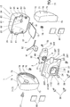
- the camera cover 1 fixes a cover main body 3 for housing the camera main body 2, a light shielding plate 5 for shielding a part of light entering the lens 4 of the camera main body 2, and the cover main body 3 And a mounting bracket 7 attached to the rear window 6 as the object, wherein the fixed object is translucent.
- the cover body 3, the light shielding plate 5 and the mounting bracket 7 are made of synthetic resin or the like.
- the cover main body 3 includes a front cover portion 11 that covers the front side of the camera body 2 that is the lens 4 side, and a rear cover portion 12 that covers the rear side of the camera body 2 that is the opposite side of the lens 4 side. .
- the camera body 2 has a cylindrical lens barrel 4A at the front center of the case elongated in the left-right direction, the lens 4 is mounted on the lens barrel 4A, and an imaging means such as an imaging device is provided inside (Not shown).
- the camera body 2 captures at least one of a still image and a moving image.
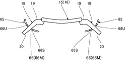
- the light shielding plate 5 has a body portion 15 which is long in the front-rear direction, and a plurality of cut-out portions 17 provided on the rear side of the body rear portion 16 which is the rear portion of the body portion 15 as described later
- the light shielding plate 5 is formed in a curved shape so that the center in the width direction is slightly lower than the left and right edges. There is.
- the front cover portion 11 is a hood that covers the front side of the camera body 2.
- the front cover portion 11 has a front plate portion 21 on the front surface, and an opening 22 at the center of the front plate portion 21.
- a rectangular outer cylinder 23 is provided behind the outer edge of the front plate 21, and the opening 22 is provided with an inner cylinder 24 that expands toward the front, and the opening 22 is provided on the front of the front plate 21.
- the bottom plate portion 25 is provided on the back side (rear side) of the inner cylindrical portion 24.
- the through hole 26 is provided in the bottom plate portion 25, and the lens cylinder portion 4A is inserted through the through hole 26. Be placed.
- the front plate portion 21 closes the space between the outer cylindrical portion 23 and the inner cylindrical portion 24 on the front side of the camera body 2.
- a hole 27 through which the main body 15 of the light shielding plate 5 can be inserted is bored in the lower part of the front plate 21, and this hole 27 is a main body of the light shielding plate 5.
- the part 15 penetrates and is formed in a laterally long curved shape following the main body part 15.
- the left and right side plate portions 23S, 23S of the outer cylinder portion 23 are formed to be wide apart from the top to the bottom, and the front plate portion 21 is also wide from the top to the bottom. Since the hole 27 can be formed wider in the left and right direction than the inner dimension of the inner cylindrical portion 24, the light shielding plate 5 wider than the inner cylindrical portion 24 can be used.
- a bowl-shaped rear plate portion 28 is provided at the rear of the outer cylindrical portion 23. Further, as shown in FIG. 3, mounting portions 31, 31 are provided on the left and right sides of the camera body 2 so as to protrude outward to the left and right, respectively, and tapping screws 32 serving as fixing means are inserted into the left and right mounting portions 31, 31. Through holes 31T and 31T are formed. Further, as shown in FIG. 5, boss portions 32A and boss portions 32A are provided on the left and right of the rear surface of the rear plate portion 28 of the front cover portion 11.
- the tapping screw 32 is inserted from the rear side into the through hole 31T of the mounting portion 31, and the tapping screw 32 is screwed to the boss portion 32A of the front cover portion 11.
- the front side of the camera body 2 is covered by the front cover portion 11 while being fixed to the rear side of the side 11.
- the rear cover portion 12 has a case shape, and includes a flat plate-like upper plate portion 33, and a curved outer plate portion 34 continuously formed from the rear edge to the rear surface and the lower surface of the upper plate portion 33.
- the cross-sectional shape of the curved outer plate portion 34 has an arc shape, and the left and right side plate portions 35 and 35 close the left and right of the upper plate portion 33 and the curved outer plate portion 34.
- the front cover portion 11 and the rear cover portion 12 are assembled by a plurality of tapping screws 36 which are fixing means.
- through holes 28T, 28T, 28T, 28T are bored at upper, lower, left and right corner portions of the rear plate portion 28 of the front cover portion 11, and these holes correspond to the through holes 28T, 28T, 28T, 28T.
- the bosses 37, 37, 37, 37 are formed in the rear cover 12, and the tapping screw 36 is inserted into the through hole 28T, and the tapping screw 36 is screwed to the boss 37. .
- half split cylindrical portions 41, 41 are respectively provided on the left and right outer side, and the front cover portion 11 and the rear cover portion 12 are assembled.
- the front cover portion 11 and the half-divided cylindrical portions 41 and 41 of the rear cover portion 12 are combined to form a connected inner cylindrical portion 42, and the bracket 7 is connected to the connected inner cylindrical portion 42.
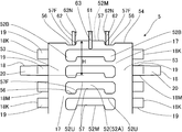
- the light shielding plate 5 is formed to have a narrower main body rear portion 16 than the main body portion 15, and on the rear side of the main body rear portion 16 constituting a part of the main body portion 15. , And a plurality of cut-out portions 17, 17... A slit-like horizontal opening 52 long in the width direction (left and right direction) of the light shielding plate 5 is provided between the adjacent cutouts 17 and 17, and the width of both left and right sides of the horizontal opening 52 is narrow.
- the connection parts 53 and 53 are comprised by the part.
- the number of cut-out portions 17, 17... Is the same as the number of lateral openings 52, and is six in FIG.
- the left and right connecting parts 53, 53 are length adjusting cutting parts that can be easily cut compared to the part of the light shielding plate 5 not provided with the lateral opening 52 by using a cutting tool or the like. It is more fragile than the portion of the light shielding plate 5 where the lateral opening 52 is not provided.
- the lateral opening 52 is half or more of the lateral width of the rear portion 16 of the main body. And when cut
- the connecting portion 53 has substantially the same thickness as the other portion of the rear portion 16 of the main body.
- the portion provided with the connecting portion 53 has a length of 1/3 or more of the portion not provided.
- the cross-sectional area of the left-right direction of the part which provided the connection part 53 of the main body rear part 16 is 1/3 or more and 1/2 or less of the cross-sectional area of another part.
- the upper side is the rear side of the light shielding plate 5 and the lower side is the front side of the light shielding plate 5, and the lateral opening 52 is then formed with the inner edge 52U in a straight line in the lateral direction.
- left and right sides are recessed forward to form left and right recesses 56, 56, and between the left and right recesses 56, 56, a convex protrusion 57 is formed on the rear side
- the left and right openings 52B and 52B on both the left and right sides are formed wider in the front-rear direction than the central opening 52A of the lateral opening 52.
- the left and right edge portions 57F and 57F of the convex portion 57 are formed in the front-rear direction so that the distance becomes narrow from the front side to the rear side.
- the central opening 52A and the left and right openings 52B and 52B are also formed linearly in the lateral direction.
- the convex portion 57 is also formed at the center in the width direction of the rear edge portion 54 of the light shielding plate 5 before the cut portion 17 is cut.
- the left and right edges of the main body rear portion 16 of the light shielding plate 5 are provided with a plurality of the locking portions 18, 18 forming a pair on the left and right at equal intervals in the front and rear.
- the integrated lateral proximal end portion 19 and the obliquely downward inclined portion 20 provided at the distal end of the proximal end portion 19 are integrally provided.
- the angle of the inclined portion 20 with respect to the horizontal is about 30 to 60 degrees.
- the distance between the front and rear locking parts 18 is the same as the distance between the front and rear cutouts 17, and the distance between the front and rear cutouts 17 is the front and rear lateral openings 52, 52.
- the locking portions 18 are provided in a pair on the left and right sides in one cut-out portion 17, and the position of the front edge 18 M of the locking portion 18 is substantially the same as the position of the front inner edge 52 M in the convex portion 57 of the lateral opening 52. Or, as shown in FIG. 9, it is located slightly backward.
- the position of the front edge 18M of the locking portion 18 is located on the rear side relative to the position of the front inner edge 52M in the recess 56 of the lateral opening 52.
- the distal end of the proximal end portion 19 is positioned on the center side in the left-right direction from the left and right edge portions on the front side of the main body portion 15. In addition, it is not necessary to provide the locking portion 18 at the time of manufacture in the last cut portion 17 before cutting.
- the light shielding plate 5 is embossed on the entire outer surface thereof. Further, as shown in FIG. 7 and FIG. 8 etc., on the upper surface on the front side of the main body portion 15 of the light shielding plate 5, except for the band-like portions 58 and 58 of constant width on the left and right sides, Are formed at intervals in the front and rear direction, and reflection of light on the upper surface of the light shielding plate 5 is suppressed by emboss processing for diffusing light and a plurality of thin ridges 59, 59. There is.
- the thin ridges 59, 59,... are reflection suppressing portions that suppress the reflection of light.
- downward convex portions 29A, 29A slightly convex downward are provided on the left and right of the upper edge of the hole 27 corresponding to the left and right band-like portions 58, 58, and At the center of the lower edge, an upward convex portion 29B slightly convex on the upper side is provided, and the left and right and center of the hole 27 is formed narrow narrowly by the convex portions 29A, 29A, 29B.
- the downward convex portion 29 ⁇ / b> A is in a position sliding on the strip portion 58.
- the upward convex portion 29 ⁇ / b> B slides on the center of the lower surface of the main body portion 15.
- a central rib 61 and left and right ribs corresponding to the rear edge 54 of the light shielding plate 5 are provided on the inner surface of the curved outer plate 34 of the rear cover 12.
- 62 and 62 are protruded, and the rib portions 61, 62 and 62 are formed in the longitudinal direction, and the central rib portion 61 is positioned at the center of the rear cover portion 12 in the left-right direction.
- at least one part of these rib parts 61, 62, 62 is a contact receiving part which the rear edge part 54 of the said light-shielding plate 5 can contact
- the left and right ribs 62, 62 abut against the rear edge 54, while not abutted against the rear edge 63K of the central rib 61, the rear edge 54 is received by the receiving groove 63 of the central rib 61. You may make it pinch from the upper and lower sides.
- the central rib portion 61 is provided with a substantially U-shaped receiving groove portion 63 recessed in the front edge at the front edge thereof, and the receiving groove portion 63 is provided with a lateral upper edge portion 63U sandwiching the upper and lower surfaces of the light shielding plate 5 As well as having a lower edge 63S, it has a longitudinal rear edge 63K to which the rear edge 54 of the light shielding plate 5 can abut. Then, the convex portion 57 of the rear edge portion 54 of the light shielding plate 5 is inserted into the receiving groove portion 63, and the vertical position of the rear edge portion 54 is regulated by the receiving groove portion 63 in the positioning state.
- the receiving groove portion 63 is a regulating portion that regulates the upper and lower positions of the rear edge portion 54 in the positioned state. Further, the distance between the upper edge portion 63U and the lower edge portion 63S is formed to be wider from the rear side to the front side, and the convex portion 57 is easily inserted.
- the receiving groove portion 63 is an engagement receiving portion engaged with the rear edge portion 54 of the light shielding plate 5, and the upper edge portion 63 U and the lower edge portion 63 S sandwiching the upper and lower surfaces of the rear edge portion 54 are the light shielding plate 5.
- the upper regulation portion and the lower regulation portion which regulate the upper and lower positions of the rear edge portion 54, and the rear edge portion 63K is a front regulation portion which regulates the rear end position of the rear edge portion 54 of the light shielding plate 5.
- the left and right rib portions 62, 62 are respectively inserted into the left and right recessed portions 56, 56 of the rear edge portion 54 of the light shielding plate 5, and the center inner surface 62N of the left and right rib portions 62, 62.
- the left and right positions of the rear edge portion 54 of the light shielding plate 5 are regulated in the positioning state by sandwiching the convex portion 57 by 62N.
- the center side inner surfaces 62N and 62N are regulating portions that regulate the left and right positions of the rear edge portion 54 of the light shielding plate 5 in a positioned state.
- receiving rib portions 65, 65 are provided protruding toward the rear side on the lower side of the rear surface of the front cover portion 11 and the receiving rib portion 65. Are provided at the lower left and right corner positions of the outer cylindrical portion 23 corresponding to the locking portions 18.
- a receiving groove 66 in which the inclined portion 20 of the locking portion 18 is inserted is recessed in the front side at the rear edge of the receiving rib 65, and the receiving groove 66 is a lateral direction sandwiching the upper and lower surfaces of the inclined portion 20.
- the upper outer edge portion 66U is located above the lower inner edge portion 66S and located outside in the left-right direction. Further, the distance between the upper outer edge portion 66U and the lower inner edge portion 66S is formed to be wider from the front side to the rear side, and the locking portion 18 is easily inserted.
- the receiving groove portion 66 is an engagement receiving portion in which the locking portion 18 is engaged, and the upper outer edge portion 66U and the lower inner edge portion 66S sandwiching the upper and lower surfaces of the inclined portion 20 are upper and lower positions of the locking portion 18. It is an upper regulation part and a lower regulation part which regulate, and the front edge 66M is a front regulation part which regulates the front end position of the locking portion 18.
- the bracket 7 includes a pair of left and right bracket bodies 71 and 71.
- the pair of bracket bodies 71 and 71 are formed substantially symmetrically in the left and right direction, and are provided to cover the left and right sides of the cover body 3.
- the bracket main body 71 has a bracket curved outer plate portion 72 mounted on the curved outer plate portion 34 of the cover main body 3, and a flat, vertically long attachment surface 73 is provided on the front side of the bracket curved outer plate portion 72.
- the mounting surface 73 is wider at the left and right than the bracket curved outer plate portion 72 and protrudes left and right outside, and side plate portions 74 are provided at the left and right outer sides of the bracket curved outer plate portion 72 and the mounting surface 73
- a connection outer cylinder portion 75 is provided on the inner surface of the portion 74, and the bracket curved outer plate portion 72 is formed around the connection outer cylinder portion 75. Then, the mounting surface 73 is adhered to the rear window 6 by the double-sided adhesive tape 80.
- the nut 76 (FIG. 3) is disposed in the rotation preventing state in the connection inner cylinder portion 42 of the cover main body 3, and the inner end side of the connection outer cylinder portion 75 is rotated to the connection inner cylinder portion 42. It is possible to attach the bracket 7 to the cover main body 3 by inserting the bolt 77 from the outside into the connecting outer cylindrical portion 75 and the connecting inner cylindrical portion 42 and screwing the bolt 77 to the nut 76 while assembling possible. it can.
- the bolt 77 is a mounting means and serves as a rotation center axis of the cover main body 3 with respect to the bracket 7.
- the angle of the cover main body 3 can be adjusted and attached to the bracket 7, and the following configuration is provided in order to make the cover main body 3 adjustable in angle.
- locking recesses 78, 78... are continuously formed in the circumferential direction, and in this example, a plurality of ridges By forming the portions 79, 79,... In the circumferential direction at intervals, the locking concave portion 78 is formed between the adjacent protruding portions 79, 79 and the inner surface of the bracket curved outer plate portion 72. There is.
- small diameter portions 82 and 82 having smaller diameters than the center in the lateral direction are formed by step portions 81 and 81,
- the small diameter portion 82 is provided with a protruding portion 83 which is a locking convex portion in the left-right direction that protrudes outward, and the bracket curved outer plate portion 72 is covered with the small diameter portion 82, and the protruding portion 83 is formed.
- the angle of the cover body 3 with respect to the bracket 7 can be set.
- the outer peripheral surfaces of the curved outer plate portions 34 and 72 are substantially flush.
- the cover body 3 and the bracket body 71 are provided with marks 85 for adjusting and setting the angle of the camera body 2.
- a plurality of marks 85A, 85A... are provided at equal intervals in the circumferential direction on the outer periphery of the bracket curved outer plate portion 72, and on the outer periphery of the curved outer plate portion 34 of the cover main body 3.
- One mark 85B is provided corresponding to the mark 85A, and the camera body 2 is desired for the bracket 7 by aligning the marks 85A and 85B at the time of attaching the bracket 7 to the camera body 2 It can be attached at an angle of Further, the mark 85B is provided corresponding to the position of the protrusion 83.
- the angle of the cover body 3 with respect to the bracket 7 can not be changed in the normal use.
- the marks 85A and 85B are configured by the convex portions, one or both may be configured by the concave portion, or may be configured by printing or the like.
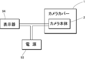
- a harness 92 is connected to the camera body 2 by a connector 91, and the harness 92 is inserted into the cover body 3 and pulled outside.
- the harness 92 is connected to a vehicle power supply 93.
- a display 94 such as liquid crystal is provided on a room mirror or the like provided on the front glass of a vehicle such as a car, and the image data of the camera body 2 is The image is sent to the display 94, and an image of the rear of the vehicle is displayed on the display 94.
- the display 94 is not limited to the one provided in the rearview mirror, and various kinds of display can be used as long as they are provided at a position where the driver can visually recognize at the front of the vehicle.
- the projection length of the light shielding plate 5 from the cover body 3 due to conditions such as the inclination of the rear window 6 can be adjusted and attached.
- the length of the light shielding plate 5 can be adjusted in units of the length of one cut-out portion 17 by changing the number of cut-out portions 17 to be cut in order to make the length suitable for the vehicle type .
- the left and right connecting portions 53, 53 near the front edge portion 18M of the locking portion 18 are made using a tool such as a cutter
- the cutting portion 17 is cut off by cutting (FIG. 8).
- the inclined portion 20 of the other locking portion 18 is cut off except for the locking portion 18 corresponding to the rear edge portion 54 of the light shielding plate 5 after the removal.
- the convex part 57 appears in the center of the rear edge part 54 which cut
- 53 ⁇ / b> K is a cut portion of the connecting portion 53.
- the distance H (FIG. 9) between the rear edge portion 54 of the convex portion 57 of the light shielding plate 5 and the front edge portion 18M of the locking portion 18 corresponding thereto is the above after assembling the cover main body 3
- the distance corresponds to the distance between the rear edge 63K of the receiving groove 63 and the front edge 66M of the receiving groove 66, and the distance is equal to or slightly larger than the distance H.
- the locking portion 18 on the rear side of the locking portion 18 corresponding to the rear edge portion 54 of the light shielding plate 5 may be left.
- the front side of the light shielding plate 5 is inserted from the back side of the front cover portion 11 into the hole 27 and the left and right locking portions 18 and 18 are The front edge 18 M of the locking portion 18 abuts on the front edge 66 M of the receiving groove 66.
- the light shielding plate 5 is temporarily fixed to the front cover 11 at three points of the hole 27 and the left and right receiving grooves 66, 66.
- the front cover 11 to which the camera body 2 is fixed is When the rear cover portion 12 is attached, the rear edge portion 54 of the light shielding plate 5 is engaged with the rib portions 61, 62, 62 of the inner surface of the rear cover portion 12, and the rear edge portion 54 of the light shielding plate 5 is positioned.
- the bracket 7 is attached to the cover main body 3.
- the cover main body 3 is assembled so that the angle of the cover main body 3 with respect to the bracket 7 becomes an angle matching the mounting condition.
- the bracket bodies 71, 71 on both sides are set to the same angle.
- one surface of the double-sided adhesive tape 80 is attached to the attachment surface 73 of the bracket main body 71, and the other surface of the double-sided adhesive tape 80 is attached to the inner surface of the rear window 6 to fix the camera cover 1 to the inner surface side of the rear window 6.
- the rear of the rear window 6 is imaged, and the light shielding plate 5 is disposed below the lens 4 and the inner surface of the rear window 6, the rear An image from below is not reflected on the inner surface of the window 6.
- the cover main body 3 for housing the camera main body 2 is provided according to claim 1, and the cover main body 3 is opposite to the lens 4 side of the camera main body 2 and the camera main body 2 There is a rear cover 12 facing the front cover 11 that covers the lens 4 side of the camera body 2, and the cover body 3 has a light shield that extends to the lens 4 side of the camera body 2 separately from the camera body 2.
- a plate 5 is provided, and the light shielding plate 5 includes a body portion 15 extending from the rear cover portion 12 side to the lens 4 side of the camera body 2, and a locking portion 18 provided on the body portion 15 and in contact with the front cover portion 11. Because it is provided with the connecting portion 53 which is a cutting portion for cutable length adjustment provided on the rear cover portion 12 side of the main body portion 15, the length adjustment of the light shielding plate 5 in the front and rear direction is achieved by cutting the connecting portion 53. It is possible.
- the rear edge 54 which is the end of the main body 15 is engaged with any of the ribs 61, 62, 62 of the rear cover 12 according to the second aspect.
- the end of the light shielding plate 5 can be supported by the following structure.
- the main body portion 15 penetrates the hole 27 formed in the front cover portion 11 corresponding to the third and fourth aspects, so that the positioning of the light shielding plate 5 is facilitated and the compact is achieved. It can be shaped.
- the mounting brackets 7 are attached to the left and right of the cover main body 3 corresponding to the fifth aspect, and the mounting is one of the inside of the mounting bracket 7 and the outside of the cover main body 3
- a locking recess 78 is continuously formed in the circumferential direction on the inner side of the bracket 7 and engaged on the outer side of the cover main body 3 which is the other of the inner side of the mounting bracket 7 and the outer side of the cover main body 3 Since the projection 83 serving as a part is provided, and the projection 83 is engaged with the engagement recess 78, the angle of the cover 3 with respect to the mounting bracket 7 can be adjusted. Both the lengths of the light shielding plate 5 can be adjusted.
- the main body portion 15 of the light shielding plate 5 is disposed on the front lower side of the lens 4, the image of the lower side of the rear window 6 reflected on the inner surface of the rear window 6 as a fixed object Can be prevented.
- the horizontal openings 52 in the width direction of the light shielding plate 5 are provided at the center in the width direction of the light shielding plate 5, and the cut portions are formed by the connecting portions 53 and 53 of the left portions of the horizontal openings 52 left and right. , And the cut-off portion 17 can be cut by cutting the connecting portions 53, 53.
- the cover body 3 is provided with a light shielding plate 5 extending toward the lens 4 of the camera body 2.
- the light shielding plate 5 is disposed on the lens 4 side of the camera body 2 from the rear cover 12 side.
- a locking portion 18 provided on the main body portion 15 and in contact with the front cover portion 11, a linking portion 53 provided on the rear cover portion 12 side of the main body portion 15 and having a shorter width than the other portions.
- the length of the light shielding plate 5 is adjusted by cutting the connecting portion 53 to adjust the rear side length of the light shielding plate 5, so that the length of the light shielding plate 5 can be easily adjusted.
- the bracket 7 is attached to the assembled cover main body 3, and the angle is adjusted to the rear window 6 as the fixed object Can be attached.
- the cut-off portion 17 which can cut and cut off the connection portion 53 which is a fragile portion is provided, and on the front side of the cut-out portion 17, a lateral opening 52 in the width direction at the center Since the connecting portions 53, 53 of the main body 15 which can be cut are provided on both sides in the width direction of the lateral opening 52, the connecting portions 53, 53 are cut to simplify the cut portion 17 having a predetermined length in the front and rear direction The length adjustment of the light shielding plate 5 becomes easy in the front-rear direction.
- the concave portions 56 and 56 and the convex portion 57 are formed in the front inner edge portion 52M of the lateral opening 52 for facilitating the cutting of the connecting portions 53 and 53, the connecting portion 53, After cutting 53, the concave portions 56 and 56 and the convex portion 57, which are the rearmost portions, can be engaged with the left and right rib portions 62 and 62 and the central rib portion 61.
- a locking recess 78 is continuously formed circumferentially on the inside of the mounting bracket 7, and a projecting ridge portion 83 which is a locking protrusion formed toward the outside of the cover main body 3 is a locking recess.
- the vertical position of the rear edge 54 can be regulated in a positioned state by the receiving groove 63 of the central rib 61, and the convex is made by the central inner surface 62N, 62N which is the holding portion of the left and right ribs 62, 62.
- the rear edge portion 54 of the light shielding plate 5 can be regulated in the left-right positioning state.
- left and right edge portions 57F, 57F of the convex portion 57 are formed so as to narrow the distance from the front side to the rear side, and are guided by the left and right edge portions 57F, 57F.
- the convex portion 57 can be smoothly inserted between 62.
- the convex portion 57 and the concave portions 56, 56 are obtained by the lateral opening 52 provided for forming the cut portion 17, and the rear edge portion 54 which becomes the rearmost portion after the cut portion is cut is a rib 61 , 62, 62 can be engaged.
- a plurality of projecting locking portions 18, 18 forming a pair on the left and right are provided at intervals in the front and back, and this interval corresponds to the interval between the excising sections 17, 17, so the light shielding plate 5 has a desired length.
- the number of the cut-out portions 17 is selected and cut out, and the lock portions 18 on the front side of the lock portion 18 are left except for the lock portions 18 and 18 corresponding to the rear edge 54 after the cut-out.
- the distance H between the front edge 18M of the foremost locking portion 18 and the convex portion 57 of the rear edge 54 is separated from the front edge 66M of the receiving groove 66 and the rear edge 63K of the receiving groove 63 by cutting. Can be made to correspond to
- a receiving groove portion 66 in which the inclined portion 20 of the locking portion 18 is engaged is provided, and the receiving groove portion 66 is recessed on the front side
- the receiving groove 66 has lateral upper outer edge 66U and lower inner edge 66S sandwiching the upper and lower surfaces of the inclined portion 20, and the distance between the upper outer edge 66U and lower inner edge 66S is wide from the front to the rear The locking portion 18 is easily inserted.
- the convex portion 57 is also formed at the center in the width direction of the rear edge portion 54 of the light shielding plate 5 before the cut-out portion 17 is cut, it is used even without cutting the cut-out portion 17 In this case, the light shield plate 5 is in the longest state.
- the reflection of light on the upper surface of the light shielding plate 5 can be suppressed by the thin ridges 59, 59 ... as the reflection suppressing portion which suppresses the reflection of light and the emboss processing as the reflection suppressing portion. Furthermore, since the light shielding plate 5 can be temporarily fixed to the front cover portion 11 at three points of the hole portion 27 and the left and right receiving groove portions 66, 66, the assembly work of the cover main body 3 thereafter can be easily performed. Can. Further, since the left and right sides of the cover main body 3 are covered by the bracket main bodies 71, 71, the cover main body 3 rotates even when the cover main body 3 is in contact with the cover main body 3 as compared with the case where the cover main body 3 is directly fixed. There is no risk of
- the sloped portion 20 of the locking portion 18 is inclined at 30 to 60 degrees with respect to the horizontal, the distance between the tips of the left and right sloped portions 20 can be narrowed. Can be miniaturized. Furthermore, on the left and right of the upper edge of the hole 27, downward convex portions 29A, 29A slightly convex downward are provided, and in the center of the lower edge of the hole 27, slightly convex upward. Since the upward convex portion 29B is provided, the main body portion 15 of the light shielding plate 5 can be stably supported at three points of the convex portions 29A, 29A, and 29B.
- the rear edge portion 54 of the light shielding plate 5 is of the curved outer plate portion 34. It does not hit other parts of the inner surface.
- 16 to 17 show a second embodiment of the present invention, in which the same parts as those of the first embodiment are designated by the same reference numerals, and detailed description thereof will be omitted.
- the locking recesses 78, 78... are continuously formed in the circumferential direction on the outer surface of the small diameter portions 82, 82 of the curved outer plate portion 34 of the cover main body 3. Further, on the inner surface of the bracket curved outer plate portion 72, the protrusion portion 83 which is a locking protrusion portion in the left-right direction is provided, and the protrusion portion 83 is locked to the locking recess 78.
- the angle of the cover main body 3 with respect to can be set.
- the mounting brackets 7 are attached to the left and right of the cover main body 3 corresponding to the fifth aspect, and the cover main body 3 is one of the inside of the mounting bracket 7 and the outside of the cover main body 3
- a plurality of locking recesses 78 are continuously formed in the circumferential direction on the outer side of the housing 7 and engaged with the inside of the mounting bracket 7 which is the other of the inside of the mounting bracket 7 and the outside of the cover body 3. Since the projection 83 serving as a projection is provided, and the projection 83 is engaged with the engagement recess 78, the angle of the cover 3 with respect to the mounting bracket 7 can be adjusted. And the length of the light shielding plate 5 can be adjusted.
- FIG. 18 shows a third embodiment of the present invention.
- the same reference numerals as in the above embodiments denote the same parts, and a detailed description thereof will be omitted.
- a cushioning material 95 is wound around a member between the rear edge portion 54 and the side opening 52, and the cushioning material 95 is disposed at the rear edge portion 54.
- the cushioning material 95 is interposed.
- the rear edge 54 which is an end of the light shielding plate 5 is in contact with the ribs 61 and 62, and in this case, the cushioning material 95 is the end of the light shielding plate 5 which abuts on the rear cover 12.
- the present invention is not limited to the present embodiment, and various modifications can be made within the scope of the present invention.
- the light shielding plate is disposed on the lower side of the lens in the embodiment, the light shielding plate is not limited to the lower side, and the light shielding plate may be disposed on the upper side, the left side or the right side of the lens.
- the plate corresponds to the buttocks of Patent Document 1.
- the light shielding plate may be provided at any one or more of the upper side, the left side, the right side and the lower side of the lens.
- the cut-out portion can be appropriately selected by providing a separation groove or a cut provided on the upper surface and / or the lower surface of the rear portion of the main body without providing the lateral opening.
Landscapes
- Physics & Mathematics (AREA)
- General Physics & Mathematics (AREA)
- Engineering & Computer Science (AREA)
- Mechanical Engineering (AREA)
- Fittings On The Vehicle Exterior For Carrying Loads, And Devices For Holding Or Mounting Articles (AREA)
- Blocking Light For Cameras (AREA)
- Accessories Of Cameras (AREA)
- Multimedia (AREA)
- Signal Processing (AREA)
- Studio Devices (AREA)
Abstract
[Problem] To provide a camera cover that accommodates a camera regardless of the object the camera is fixed to, and that allows length adjustment of a light-blocking plate. [Solution] This camera cover 1 comprises a cover body 3 that accommodates a camera body 2, the cover body 3 including: a rear cover portion 12 that faces the camera body 2 on the side opposite to a lens 4 of the camera body 2; and a front cover portion 11 that covers the lens 4 side of the camera body 2. The cover body 3 is provided with a light-blocking plate 5 which is separate from the camera body 2, the light-blocking plate extending towards the lens 4 of the camera body 2. The light-blocking plate 5 comprises: a body portion 15 that extends from the rear cover portion 12 towards the lens 4 of the camera body 2; a locking portion that is provided on the body portion 15 and that abuts the front cover portion 11; and a linking portion 53 that is provided on the rear cover portion 12 side of the body portion 15 and that can be cut, and thus, by cutting the linking portion 53, it is possible to adjust the length of the light-blocking plate 5 in the front-rear direction.
Description
本発明は、遮光板を備えたカメラカバーに関する。
The present invention relates to a camera cover provided with a light shielding plate.
従来、この種のものとして、レンズおよび撮像素子を備えた車載カメラであって、前記レンズおよび撮像素子と、これらレンズ、撮像素子を収納する本体ケースとを有するカメラ本体部と、カメラの視野と重複しないように、前記カメラ本体部を覆う上板部,側板部及び下板部を設けたブラケットとを備え、このブラケットの前記上板部は、前記本体ケースにおいて前記レンズが装着されているレンズ装着面よりも突き出しており、かつ、前記側板部よりも前記レンズ装着面に対して突き出した庇部を備えた車載カメラ(例えば特許文献1)が提案されている。
Heretofore, an on-vehicle camera having a lens and an imaging device as this type of camera, the camera body including the lens and the imaging device, the lens, and a body case for housing the imaging device, and a field of view of the camera A bracket provided with an upper plate portion, a side plate portion, and a lower plate portion covering the camera body portion so as not to overlap, the upper plate portion of the bracket is a lens on which the lens is mounted in the body case An on-vehicle camera (for example, Patent Document 1) has been proposed that includes a hook that protrudes beyond the mounting surface and that protrudes with respect to the lens mounting surface more than the side plate.
また、上記車載カメラは、車両のフロントガラスの車室内面に固定されるようになっており、前記ブラケットをフロントガラスの車室内面に連結するアームを備えている。
Further, the on-vehicle camera is fixed to a vehicle interior surface of a windshield of the vehicle, and includes an arm connecting the bracket to the vehicle interior surface of the windshield.
上記車載カメラでは、アームをフロントガラスに接着することにより、車載カメラをフロントガラスなどの内側に取り付けることができる。また、庇部を備えたブラケットにより、上方,側方や下方からカメラ本体部に向かう太陽光が、カメラ本体部に当たることを抑制できる。
In the on-vehicle camera, the on-vehicle camera can be attached to the inside of the windshield or the like by bonding the arm to the windshield. In addition, it is possible to suppress that sunlight directed to the camera main body from above, sides, or lower hits the camera main body by the bracket provided with the buttocks.
しかし、上記車載カメラでは、庇部などの寸法を調整することができないため、車種や取付場所が変わると、不要な太陽光がレンズに入ったり不要な部分が撮像されたりする虞がある。
However, since the dimensions of the buttocks and the like can not be adjusted with the above-described on-vehicle camera, there is a possibility that unnecessary sunlight may enter the lens or an unnecessary portion may be imaged if the vehicle type or the mounting location changes.
また、上記車載カメラの下板部は光の一部を遮ることはできるが、カメラ本体部と固定対象物であるフロントガラスやリアウインドウなどとの角度によっては、固定対象物の車内側内面で反射した光が、カメラ本体の画角内に入り込み、例えば、固定対象物の下方に位置するダッシュボードや後部に搭載した荷物の画像が写り込んでしまうという問題がある。
The lower plate of the on-vehicle camera can block part of the light, but depending on the angle between the camera body and the windshield or rear window that is the fixed object, There is a problem that the reflected light gets into the angle of view of the camera body and, for example, an image of a dashboard located below the fixed object or an image of a load mounted on the rear is captured.
そこで、仮に、従来のブラケットにより写り込みを防止しようとしても、車種や前後のガラスでは固定条件が異なるため、専用のブラケットを用意する必要があり、コストが掛かるという問題がある。
Therefore, even if it is attempted to prevent the reflection by means of the conventional bracket, the vehicle and the front and rear glass have different fixing conditions, so it is necessary to prepare a dedicated bracket, which causes a problem of cost increase.
そこで、本発明は上記した問題点に鑑み、固定対象物が異なる場合でも対応可能で、遮光板の長さを調整することができるカメラカバーを提供することを目的とする。
Therefore, in view of the above-described problems, the present invention has an object to provide a camera cover which can cope with different fixed objects and can adjust the length of the light shielding plate.
上記目的を達成するために、請求項1に係る発明は、カメラ本体を収納するカバー本体を備え、前記カバー本体が、前記カメラ本体のレンズ側とは反対側で前記カメラ本体と対向する後カバー部と、前記カメラ本体のレンズ側を覆う前カバー部とを有し、前記カバー本体には、前記カメラ本体とは別に、前記カメラ本体のレンズ側に延びる遮光板が設けられ、前記遮光板は、前記後カバー部側から前記カメラ本体のレンズ側に延びる本体部と、前記本体部に設けられ前記前カバー部に当接する係止部と、前記本体部の前記後カバー部側に設けられた切断可能な長さ調整用切断部とを備えることを特徴とする。
In order to achieve the above object, the invention according to claim 1 includes a cover main body for housing a camera main body, and the cover main body is a rear cover facing the camera main body on the side opposite to the lens side of the camera main body. Part and a front cover part that covers the lens side of the camera body, the cover body being provided with a light shielding plate extending to the lens side of the camera body separately from the camera body, the light shielding plate being A main body portion extending from the rear cover portion side to a lens side of the camera body, a locking portion provided on the main body portion and in contact with the front cover portion, and provided on the rear cover portion side of the main body portion And a cutting unit for adjusting the length.
請求項2に係る発明は、前記本体部の端部が前記後カバー部に係合することを特徴とする。
The invention according to claim 2 is characterized in that an end portion of the main body portion engages with the rear cover portion.
請求項3及び4に係る発明は、前記本体部が前記前カバー部に形成された孔部を貫通することを特徴とする。
The invention according to claims 3 and 4 is characterized in that the main body portion penetrates a hole formed in the front cover portion.
請求項5に係る発明は、前記カバー本体に取付け用ブラケットが取り付けられており、前記取付け用ブラケットの内側と前記カバー本体の外側の一方には、周方向に複数の係止凹部が連続して形成されており、前記取付け用ブラケットの内側と前記カバー本体の外側の他方には、係止凸部を設け、前記係止凸部が前記係止凹部に係合することにより前記取付け用ブラケットに対して前記カバー本体の角度を調整可能に構成したことを特徴とする。
In the invention according to claim 5, a mounting bracket is attached to the cover main body, and a plurality of locking recesses are continuously formed in the circumferential direction on one of the inner side of the mounting bracket and the outer side of the cover main body. A locking projection is provided on the other of the inside of the mounting bracket and the outside of the cover main body, and the locking convex is engaged with the locking recess to the mounting bracket. On the other hand, the angle of the cover main body can be adjusted.
請求項1の構成によれば、前後方向における遮光板の長さ調整が可能である。
According to the structure of Claim 1, the length adjustment of the light-shielding plate in the front-back direction is possible.
請求項2の構成によれば、簡単な構造で遮光板を支持できる。
According to the configuration of claim 2, the light shielding plate can be supported with a simple structure.
請求項3及び4の構成によれば、遮光板の位置決めを容易にしつつ、コンパクトな形状とすることができる。
According to the configuration of claims 3 and 4, the light shielding plate can be made compact while facilitating the positioning of the light shielding plate.
請求項5の構成によれば、カメラ本体の角度と遮光板の長さの双方を調整可能とすることができる。
According to the configuration of claim 5, it is possible to adjust both the angle of the camera body and the length of the light shielding plate.
以下、図面を参照して、本発明のカメラカバーの実施例について説明する。
Hereinafter, embodiments of the camera cover of the present invention will be described with reference to the drawings.
図1~図15は本発明の実施例1を示す。同図に示すように、カメラカバー1は、カメラ本体2を収容するカバー本体3と、このカメラ本体2のレンズ4に入る光の一部を遮光する遮光板5と、前記カバー本体3を固定対象物たるリアウインドウ6に取り付ける取付け用ブラケット7とを備え、前記固定対象物は透光性を有する。尚、カバー本体3,遮光板5及び取付け用ブラケット7は合成樹脂などからなる。
1 to 15 show Embodiment 1 of the present invention. As shown in the figure, the camera cover 1 fixes a cover main body 3 for housing the camera main body 2, a light shielding plate 5 for shielding a part of light entering the lens 4 of the camera main body 2, and the cover main body 3 And a mounting bracket 7 attached to the rear window 6 as the object, wherein the fixed object is translucent. The cover body 3, the light shielding plate 5 and the mounting bracket 7 are made of synthetic resin or the like.
前記カバー本体3は、前記カメラ本体2のレンズ4側である前側を覆う前カバー部11と、前記カメラ本体2の前記レンズ4側とは反対側である後側を覆う後カバー部12を備える。
The cover main body 3 includes a front cover portion 11 that covers the front side of the camera body 2 that is the lens 4 side, and a rear cover portion 12 that covers the rear side of the camera body 2 that is the opposite side of the lens 4 side. .
前記カメラ本体2は、左右方向に長いケースの前部中央に円筒形のレンズ筒部4Aを有し、このレンズ筒部4Aに前記レンズ4が装着されており、内部に撮像素子などの撮像手段(図示せず)を備える。尚、カメラ本体2は静止画・動画の少なくとも一方を撮像するものである。
The camera body 2 has a cylindrical lens barrel 4A at the front center of the case elongated in the left-right direction, the lens 4 is mounted on the lens barrel 4A, and an imaging means such as an imaging device is provided inside (Not shown). The camera body 2 captures at least one of a still image and a moving image.
前記遮光板5は、前後方向に長い本体部15と、後述するように前記本体部15の後部である本体後部16の後側に複数設けた切除部17,17・・・と、前記本体後部16の左右縁から左右外側に突設した係止突起たる係止部18,18とを有し、前記遮光板5は幅方向中央が左右縁より僅かに低くなるように湾曲状に形成されている。
The light shielding plate 5 has a body portion 15 which is long in the front-rear direction, and a plurality of cut-out portions 17 provided on the rear side of the body rear portion 16 which is the rear portion of the body portion 15 as described later The light shielding plate 5 is formed in a curved shape so that the center in the width direction is slightly lower than the left and right edges. There is.
前記前カバー部11は、カメラ本体2の前側を覆うフードであって、この前カバー部11は前面に前板部21を有し、この前板部21の中央に開口部22を有し、前記前板部21の外縁部の後方に角型の外筒部23を備え、前記開口部22に、前側に拡大する内筒部24を設け、前記前板部21の前側に前記開口部22が位置し、前記内筒部24の奥側(後側)には底板部25が設けられており、この底板部25に透孔26を設け、この透孔26に前記レンズ筒部4Aが挿通配置される。そして、前記前板部21により、カメラ本体2の前側において前記外筒部23と内筒部24の間を塞いでいる。
The front cover portion 11 is a hood that covers the front side of the camera body 2. The front cover portion 11 has a front plate portion 21 on the front surface, and an opening 22 at the center of the front plate portion 21. A rectangular outer cylinder 23 is provided behind the outer edge of the front plate 21, and the opening 22 is provided with an inner cylinder 24 that expands toward the front, and the opening 22 is provided on the front of the front plate 21. The bottom plate portion 25 is provided on the back side (rear side) of the inner cylindrical portion 24. The through hole 26 is provided in the bottom plate portion 25, and the lens cylinder portion 4A is inserted through the through hole 26. Be placed. The front plate portion 21 closes the space between the outer cylindrical portion 23 and the inner cylindrical portion 24 on the front side of the camera body 2.
図4などに示すように、前記前板部21の下部には、前記遮光板5の本体部15を挿通可能な孔部27が穿設され、この孔部27は、前記遮光板5の本体部15が貫通し、この本体部15に倣って横方向に長い湾曲状に形成されている。
As shown in FIG. 4 and the like, a hole 27 through which the main body 15 of the light shielding plate 5 can be inserted is bored in the lower part of the front plate 21, and this hole 27 is a main body of the light shielding plate 5. The part 15 penetrates and is formed in a laterally long curved shape following the main body part 15.
この場合、外筒部23の左,右側板部23S,23Sは上から下に向かって間隔が広くなるように形成されており、前板部21も上から下に向かって左右幅広になるように形成されているから、内筒部24の内寸法より孔部27を左右幅広に形成することができ、内筒部24より幅広な遮光板5を使用できる。
In this case, the left and right side plate portions 23S, 23S of the outer cylinder portion 23 are formed to be wide apart from the top to the bottom, and the front plate portion 21 is also wide from the top to the bottom. Since the hole 27 can be formed wider in the left and right direction than the inner dimension of the inner cylindrical portion 24, the light shielding plate 5 wider than the inner cylindrical portion 24 can be used.
前記外筒部23の後部には鍔状の後板部28が設けられている。また、図3に示すように、前記カメラ本体2の左右には、取付部31,31が左右外側に突設され、これら左右の取付部31,31に、固定手段たるタッピングネジ32を挿通する透孔31T,31Tが穿設されている。また、図5に示すように、前カバー部11の後板部28の後面左右にボス部32A,ボス部32Aを設けている。
A bowl-shaped rear plate portion 28 is provided at the rear of the outer cylindrical portion 23. Further, as shown in FIG. 3, mounting portions 31, 31 are provided on the left and right sides of the camera body 2 so as to protrude outward to the left and right, respectively, and tapping screws 32 serving as fixing means are inserted into the left and right mounting portions 31, 31. Through holes 31T and 31T are formed. Further, as shown in FIG. 5, boss portions 32A and boss portions 32A are provided on the left and right of the rear surface of the rear plate portion 28 of the front cover portion 11.
そして、前記取付部31の透孔31Tにタッピングネジ32を後側から挿通し、このタッピングネジ32を、前カバー部11のボス部32Aに螺着することにより、前記カメラ本体2が前カバー部11の後側に固定されると共に、カメラ本体2の前側が前カバー部11により覆われる。
Then, the tapping screw 32 is inserted from the rear side into the through hole 31T of the mounting portion 31, and the tapping screw 32 is screwed to the boss portion 32A of the front cover portion 11. The front side of the camera body 2 is covered by the front cover portion 11 while being fixed to the rear side of the side 11.
前記後カバー部12は、ケース状をなし、平板状の上板部33と、この上板部33の後縁から後面と下面に連続して形成された湾曲外板部34とを備え、この湾曲外板部34の断面形状は円弧状をなし、それら上板部33と湾曲外板部34の左右を左,右側板部35,35により塞いでいる。
The rear cover portion 12 has a case shape, and includes a flat plate-like upper plate portion 33, and a curved outer plate portion 34 continuously formed from the rear edge to the rear surface and the lower surface of the upper plate portion 33. The cross-sectional shape of the curved outer plate portion 34 has an arc shape, and the left and right side plate portions 35 and 35 close the left and right of the upper plate portion 33 and the curved outer plate portion 34.
そして、図3に示すように、前記前カバー部11と後カバー部12は、固定手段たる複数のタッピングネジ36により組み立てられる。尚、前記前カバー部11の後板部28の上下左右の角部には、透孔28T,28T,28T,28Tが穿設されており、これら透孔28T,28T,28T,28Tに対応して、前記後カバー部12内にボス部37,37,37,37が形成され、前記透孔28Tに前記タッピングネジ36を挿通し、このタッピングネジ36を前記ボス部37に螺着している。
Then, as shown in FIG. 3, the front cover portion 11 and the rear cover portion 12 are assembled by a plurality of tapping screws 36 which are fixing means. Incidentally, through holes 28T, 28T, 28T, 28T are bored at upper, lower, left and right corner portions of the rear plate portion 28 of the front cover portion 11, and these holes correspond to the through holes 28T, 28T, 28T, 28T. The bosses 37, 37, 37, 37 are formed in the rear cover 12, and the tapping screw 36 is inserted into the through hole 28T, and the tapping screw 36 is screwed to the boss 37. .
また、前記前カバー部11と後カバー部12の突き合せ箇所の左右には、半割筒部41,41がそれぞれ左右外側に突設され、前記前カバー部11と後カバー部12を組み立てることにより、前カバー部11と後カバー部12の半割筒部41,41が組み合わされて連結内筒部42が形成され、この連結内筒部42に前記ブラケット7が連結される。
Further, on the left and right of the butt between the front cover portion 11 and the rear cover portion 12, half split cylindrical portions 41, 41 are respectively provided on the left and right outer side, and the front cover portion 11 and the rear cover portion 12 are assembled. Thus, the front cover portion 11 and the half-divided cylindrical portions 41 and 41 of the rear cover portion 12 are combined to form a connected inner cylindrical portion 42, and the bracket 7 is connected to the connected inner cylindrical portion 42.
図7及び図8などに示すように、前記遮光板5は、前記本体部15に比べて本体後部16が幅狭に形成され、本体部15の一部を構成する本体後部16の後側に、前後方向に並んで複数の切除部17,17・・・を有する。隣り合う切除部17,17の間には、遮光板5の幅方向(左右方向)に長いスリット状の横開口部52が設けられていると共に、この横開口部52の左右両側の幅狭な部分により連結部53,53を構成している。尚、切除部17,17・・・の数は、横開口部52の数と同一であり、図7では6つである。
As shown in FIG. 7 and FIG. 8 etc., the light shielding plate 5 is formed to have a narrower main body rear portion 16 than the main body portion 15, and on the rear side of the main body rear portion 16 constituting a part of the main body portion 15. , And a plurality of cut-out portions 17, 17... A slit-like horizontal opening 52 long in the width direction (left and right direction) of the light shielding plate 5 is provided between the adjacent cutouts 17 and 17, and the width of both left and right sides of the horizontal opening 52 is narrow. The connection parts 53 and 53 are comprised by the part. The number of cut-out portions 17, 17... Is the same as the number of lateral openings 52, and is six in FIG.
前記左右の連結部53,53は、切断用の工具等を用いることにより、横開口部52を設けていない遮光板5の部分に比べて容易に切断可能な長さ調整用切断部であり、横開口部52を設けていない遮光板5の部分に比べて脆弱である。尚、横開口部52は本体後部16の左右幅の1/2以上である。そして、遮光板5を切断する場合、連結部53を設けた部分は設けていない分の1/2以下の長さを切断するだけで済む。尚、連結部53は本体後部16の他の部分と略同一厚さである。また、強度上、連結部53を設けた部分は設けていない分の1/3以上の長さにすることが好ましい。そして、本体後部16の連結部53を設けた部分の左右方向の断面積は、他の部分の断面積の1/3以上、1/2以下である。
The left and right connecting parts 53, 53 are length adjusting cutting parts that can be easily cut compared to the part of the light shielding plate 5 not provided with the lateral opening 52 by using a cutting tool or the like. It is more fragile than the portion of the light shielding plate 5 where the lateral opening 52 is not provided. The lateral opening 52 is half or more of the lateral width of the rear portion 16 of the main body. And when cut | disconnecting the light-shielding plate 5, the part which provided the connection part 53 only cut | disconnects the half or less length of the part which is not provided. The connecting portion 53 has substantially the same thickness as the other portion of the rear portion 16 of the main body. Further, in terms of strength, it is preferable that the portion provided with the connecting portion 53 has a length of 1/3 or more of the portion not provided. And the cross-sectional area of the left-right direction of the part which provided the connection part 53 of the main body rear part 16 is 1/3 or more and 1/2 or less of the cross-sectional area of another part.
図7~図9において、上側が遮光板5の後側、下側が遮光板5の前側であり、前記横開口部52は、その後内縁部52Uが横方向に直線状に形成され、前記横開口部52の前内縁部52Mには、左右両側が前側に凹んで左右の凹部56,56が形成されると共に、これら左右の凹部56,56の間に、後側に凸な凸部57が形成され、これにより横開口部52の中央開口部52Aに比べて左右両側の左右開口部52B,52Bが前後方向幅広に形成されている。そして、前記凸部57の左右縁部57F,57Fは、前側から後側に向かって間隔が狭くなるように前後方向に形成されている。尚、横開口部52の前内縁部52Mは、中央開口部52Aと左右開口部52B,52Bの部分も横方向に直線状に形成されている。また、図7に示すように、切除部17を切除する前の遮光板5の後縁部54にも、その幅方向中央に前記凸部57が形成されている。
In FIGS. 7 to 9, the upper side is the rear side of the light shielding plate 5 and the lower side is the front side of the light shielding plate 5, and the lateral opening 52 is then formed with the inner edge 52U in a straight line in the lateral direction. On the front inner edge 52M of the portion 52, left and right sides are recessed forward to form left and right recesses 56, 56, and between the left and right recesses 56, 56, a convex protrusion 57 is formed on the rear side Thus, the left and right openings 52B and 52B on both the left and right sides are formed wider in the front-rear direction than the central opening 52A of the lateral opening 52. The left and right edge portions 57F and 57F of the convex portion 57 are formed in the front-rear direction so that the distance becomes narrow from the front side to the rear side. In the front inner edge 52M of the lateral opening 52, the central opening 52A and the left and right openings 52B and 52B are also formed linearly in the lateral direction. Further, as shown in FIG. 7, the convex portion 57 is also formed at the center in the width direction of the rear edge portion 54 of the light shielding plate 5 before the cut portion 17 is cut.
前記遮光板5の本体後部16の左右縁部には、左右で対をなす前記係止部18,18が前後に等間隔で複数設けられ、前記係止部18は、左右方向外側に突設された横方向の基端部19と、この基端部19の先端に設けられた斜め下向きの傾斜部20とを一体に備える。この傾斜部20の水平に対する角度は30~60度程度である。尚、前後の係止部18,18の間隔は、前後の前記切除部17,17の間隔と同一であり、また、前後の切除部17,17の間隔は前後の前記横開口部52,52の間隔と同一である。前記係止部18は1つの切除部17に左右一対ずつ設けられ、係止部18の前縁部18Mの位置は、前記横開口部52の凸部57における前内縁部52Mの位置と略同一か、図9に示すように、僅かに後方に位置する。尚、係止部18の前縁部18Mの位置は、前記横開口部52の凹部56における前内縁部52Mの位置に比べて後側に位置する。前記基端部19の先端は、前記本体部15の前側の左右縁部より左右方向中央側に位置する。また、切断前の最後部の切除部17には、製造時に係止部18を設ける必要はない。
The left and right edges of the main body rear portion 16 of the light shielding plate 5 are provided with a plurality of the locking portions 18, 18 forming a pair on the left and right at equal intervals in the front and rear. The integrated lateral proximal end portion 19 and the obliquely downward inclined portion 20 provided at the distal end of the proximal end portion 19 are integrally provided. The angle of the inclined portion 20 with respect to the horizontal is about 30 to 60 degrees. The distance between the front and rear locking parts 18 is the same as the distance between the front and rear cutouts 17, and the distance between the front and rear cutouts 17 is the front and rear lateral openings 52, 52. Same as the interval of The locking portions 18 are provided in a pair on the left and right sides in one cut-out portion 17, and the position of the front edge 18 M of the locking portion 18 is substantially the same as the position of the front inner edge 52 M in the convex portion 57 of the lateral opening 52. Or, as shown in FIG. 9, it is located slightly backward. The position of the front edge 18M of the locking portion 18 is located on the rear side relative to the position of the front inner edge 52M in the recess 56 of the lateral opening 52. The distal end of the proximal end portion 19 is positioned on the center side in the left-right direction from the left and right edge portions on the front side of the main body portion 15. In addition, it is not necessary to provide the locking portion 18 at the time of manufacture in the last cut portion 17 before cutting.
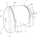
前記遮光板5には、その外面全体にシボ加工が施されている。また、図7及び図8などに示すように、遮光板5の本体部15の前側の上面には、左右縁側の一定幅の帯状部分58,58を除いて、横方向の細い突条部59が前後方向に間隔を置いて複数形成され、光を拡散するシボ加工と複数の細い突条部59,59・・・により、遮光板5の上面における光の上方向への反射を抑制している。
The light shielding plate 5 is embossed on the entire outer surface thereof. Further, as shown in FIG. 7 and FIG. 8 etc., on the upper surface on the front side of the main body portion 15 of the light shielding plate 5, except for the band- like portions 58 and 58 of constant width on the left and right sides, Are formed at intervals in the front and rear direction, and reflection of light on the upper surface of the light shielding plate 5 is suppressed by emboss processing for diffusing light and a plurality of thin ridges 59, 59. There is.
このように細い突条部59,59・・・は光の反射を抑制する反射抑制部である。また、前記左右の帯状部分58,58に対応して、前記孔部27の上縁の左右には、下側に僅かに凸な下向き凸部29A,29Aを設け、また、前記孔部27の下縁の中央には、上側に僅かに凸な上向き凸部29Bを設け、それら凸部29A,29A,29Bにより孔部27の左右及び中央が上下幅狭に形成されている。尚、図2に示すように、前記下向き凸部29Aは帯状部分58に摺動する位置にある。また、前記本体部15を前記孔部27に挿入する際、前記上向き凸部29Bは前記本体部15の下面中央に摺動する。
As described above, the thin ridges 59, 59,... Are reflection suppressing portions that suppress the reflection of light. Further, downward convex portions 29A, 29A slightly convex downward are provided on the left and right of the upper edge of the hole 27 corresponding to the left and right band- like portions 58, 58, and At the center of the lower edge, an upward convex portion 29B slightly convex on the upper side is provided, and the left and right and center of the hole 27 is formed narrow narrowly by the convex portions 29A, 29A, 29B. As shown in FIG. 2, the downward convex portion 29 </ b> A is in a position sliding on the strip portion 58. Further, when the main body portion 15 is inserted into the hole portion 27, the upward convex portion 29 </ b> B slides on the center of the lower surface of the main body portion 15.
図10及び図11などに示すように、前記後カバー部12の前記湾曲外板部34の内面には、前記遮光板5の後縁部54に対応して、中央リブ部61と左右リブ部62,62が突設され、これらリブ部61,62,62は、縦方向に形成され、中央リブ部61は後カバー部12の左右方向中央に位置する。そして、それらリブ部61,62,62の少なくとも一部は、前記遮光板5の後縁部54が当接可能な当接受け部である。例えば、左右リブ部62、62が後縁部54に当接し、一方、中央リブ部61の後縁部63Kには当接せずに、中央リブ部61の受け溝部63で後縁部54を上下から挟むようにしてもよい。
As shown in FIGS. 10 and 11, on the inner surface of the curved outer plate 34 of the rear cover 12, a central rib 61 and left and right ribs corresponding to the rear edge 54 of the light shielding plate 5 are provided. 62 and 62 are protruded, and the rib portions 61, 62 and 62 are formed in the longitudinal direction, and the central rib portion 61 is positioned at the center of the rear cover portion 12 in the left-right direction. And at least one part of these rib parts 61, 62, 62 is a contact receiving part which the rear edge part 54 of the said light-shielding plate 5 can contact | abut. For example, the left and right ribs 62, 62 abut against the rear edge 54, while not abutted against the rear edge 63K of the central rib 61, the rear edge 54 is received by the receiving groove 63 of the central rib 61. You may make it pinch from the upper and lower sides.
前記中央リブ部61には、その前縁に略コ字形の受け溝部63が後側に凹んで設けられ、この受け溝部63は、遮光板5の上下面を挟む横方向の上縁部63Uと下縁部63Sを有すると共に、遮光板5の後縁部54が当接可能な縦方向の後縁部63Kを有する。そして、受け溝部63内に前記遮光板5の後縁部54の凸部57が係入し、その受け溝部63により後縁部54の上下位置が位置決め状態で規制される。このように受け溝部63は、後縁部54の上下位置を位置決め状態で規制する規制部である。また、上縁部63Uと下縁部63Sの間隔は後側から前側に向かって広くなるように形成されており、前記凸部57が入り易くなっている。
The central rib portion 61 is provided with a substantially U-shaped receiving groove portion 63 recessed in the front edge at the front edge thereof, and the receiving groove portion 63 is provided with a lateral upper edge portion 63U sandwiching the upper and lower surfaces of the light shielding plate 5 As well as having a lower edge 63S, it has a longitudinal rear edge 63K to which the rear edge 54 of the light shielding plate 5 can abut. Then, the convex portion 57 of the rear edge portion 54 of the light shielding plate 5 is inserted into the receiving groove portion 63, and the vertical position of the rear edge portion 54 is regulated by the receiving groove portion 63 in the positioning state. As described above, the receiving groove portion 63 is a regulating portion that regulates the upper and lower positions of the rear edge portion 54 in the positioned state. Further, the distance between the upper edge portion 63U and the lower edge portion 63S is formed to be wider from the rear side to the front side, and the convex portion 57 is easily inserted.
そして、受け溝部63が、前記遮光板5の後縁部54が係合する係合受け部であり、その後縁部54の上下面を挟む上縁部63U及び下縁部63Sが、遮光板5の後縁部54の上下位置を規制する上規制部及び下規制部であり、後縁部63Kが、遮光板5の後縁部54の後端位置を規制する前規制部である。
The receiving groove portion 63 is an engagement receiving portion engaged with the rear edge portion 54 of the light shielding plate 5, and the upper edge portion 63 U and the lower edge portion 63 S sandwiching the upper and lower surfaces of the rear edge portion 54 are the light shielding plate 5. The upper regulation portion and the lower regulation portion which regulate the upper and lower positions of the rear edge portion 54, and the rear edge portion 63K is a front regulation portion which regulates the rear end position of the rear edge portion 54 of the light shielding plate 5.
図9に示すように、前記左右リブ部62,62は、それぞれ遮光板5の後縁部54の左右の凹部56,56に挿入され、且つ、左右リブ部62,62の中央側内面62N,62Nにより前記凸部57を挟み、遮光板5の後縁部54の左右位置が位置決め状態で規制される。このように前記中央側内面62N,62Nは、遮光板5の後縁部54の左右位置を位置決め状態で規制する規制部である。
As shown in FIG. 9, the left and right rib portions 62, 62 are respectively inserted into the left and right recessed portions 56, 56 of the rear edge portion 54 of the light shielding plate 5, and the center inner surface 62N of the left and right rib portions 62, 62. The left and right positions of the rear edge portion 54 of the light shielding plate 5 are regulated in the positioning state by sandwiching the convex portion 57 by 62N. As described above, the center side inner surfaces 62N and 62N are regulating portions that regulate the left and right positions of the rear edge portion 54 of the light shielding plate 5 in a positioned state.
図5、図6及び図12などに示すように、前記前カバー部11の後面の下側左右には、後側に向かって、受けリブ部65,65が突設され、この受けリブ部65は前記係止部18に対応して前記外筒部23の下側の左右角部位置に設けられている。前記受けリブ部65の後縁には前記係止部18の傾斜部20が係入する受け溝部66が前側に凹んで設けられ、この受け溝部66は、傾斜部20の上下面を挟む横方向の上外縁部66Uと下内縁部66Sを有すると共に、傾斜部20の後縁部が当接可能な縦方向の前縁部66Mを有する。尚、上外縁部66Uは下内縁部66Sより上部に位置すると共に、左右方向外側に位置する。また、上外縁部66Uと下内縁部66Sの間隔は前側から後側に向かって広くなるように形成されており、前記係止部18が入り易くなっている。
As shown in FIG. 5, FIG. 6 and FIG. 12 etc., receiving rib portions 65, 65 are provided protruding toward the rear side on the lower side of the rear surface of the front cover portion 11 and the receiving rib portion 65. Are provided at the lower left and right corner positions of the outer cylindrical portion 23 corresponding to the locking portions 18. A receiving groove 66 in which the inclined portion 20 of the locking portion 18 is inserted is recessed in the front side at the rear edge of the receiving rib 65, and the receiving groove 66 is a lateral direction sandwiching the upper and lower surfaces of the inclined portion 20. And a vertical front edge 66M against which the rear edge of the inclined portion 20 can abut. The upper outer edge portion 66U is located above the lower inner edge portion 66S and located outside in the left-right direction. Further, the distance between the upper outer edge portion 66U and the lower inner edge portion 66S is formed to be wider from the front side to the rear side, and the locking portion 18 is easily inserted.
そして、受け溝部66が、前記係止部18が係入する係入受け部であり、傾斜部20の上下面を挟む上外縁部66U及び下内縁部66Sが、係止部18の上下位置を規制する上規制部及び下規制部であり、前縁部66Mが、係止部18の前端位置を規制する前規制部である。
The receiving groove portion 66 is an engagement receiving portion in which the locking portion 18 is engaged, and the upper outer edge portion 66U and the lower inner edge portion 66S sandwiching the upper and lower surfaces of the inclined portion 20 are upper and lower positions of the locking portion 18. It is an upper regulation part and a lower regulation part which regulate, and the front edge 66M is a front regulation part which regulates the front end position of the locking portion 18.
前記ブラケット7は、左右一対のブラケット本体71,71を備え、これら一対のブラケット本体71,71は、略左右対称に形成され、前記カバー本体3の左右側部を覆うように設けられる。前記ブラケット本体71は、前記カバー本体3の湾曲外板部34に外装するブラケット湾曲外板部72を有し、このブラケット湾曲外板部72の前側に、平坦で上下方向に長い取付面73を設け、この取付面73は前記ブラケット湾曲外板部72より左右に幅広で、左右外側に出っ張っており、それらブラケット湾曲外板部72と取付面73の左右外側に側板部74を設け、この側板部74の内面に連結外筒部75を設け、この連結外筒部75を中心として前記ブラケット湾曲外板部72が形成されている。そして、前記取付面73が両面粘着テープ80によりリアウインドウ6に接着される。
The bracket 7 includes a pair of left and right bracket bodies 71 and 71. The pair of bracket bodies 71 and 71 are formed substantially symmetrically in the left and right direction, and are provided to cover the left and right sides of the cover body 3. The bracket main body 71 has a bracket curved outer plate portion 72 mounted on the curved outer plate portion 34 of the cover main body 3, and a flat, vertically long attachment surface 73 is provided on the front side of the bracket curved outer plate portion 72. The mounting surface 73 is wider at the left and right than the bracket curved outer plate portion 72 and protrudes left and right outside, and side plate portions 74 are provided at the left and right outer sides of the bracket curved outer plate portion 72 and the mounting surface 73 A connection outer cylinder portion 75 is provided on the inner surface of the portion 74, and the bracket curved outer plate portion 72 is formed around the connection outer cylinder portion 75. Then, the mounting surface 73 is adhered to the rear window 6 by the double-sided adhesive tape 80.
ブラケット7の取付けにおいては、カバー本体3の連結内筒部42内にナット76(図3)を回り止め状態で配置し、その連結内筒部42に連結外筒部75の内端側を回転可能に外装すると共に、外側から連結外筒部75と連結内筒部42にボルト77を挿通し、このボルト77を前記ナット76に螺合することにより、カバー本体3にブラケット7を取り付けることができる。そして、ボルト77は、取付手段であって、ブラケット7に対するカバー本体3の回転中心軸となる。
In mounting the bracket 7, the nut 76 (FIG. 3) is disposed in the rotation preventing state in the connection inner cylinder portion 42 of the cover main body 3, and the inner end side of the connection outer cylinder portion 75 is rotated to the connection inner cylinder portion 42. It is possible to attach the bracket 7 to the cover main body 3 by inserting the bolt 77 from the outside into the connecting outer cylindrical portion 75 and the connecting inner cylindrical portion 42 and screwing the bolt 77 to the nut 76 while assembling possible. it can. The bolt 77 is a mounting means and serves as a rotation center axis of the cover main body 3 with respect to the bracket 7.
カバー本体3にブラケット7を取り付ける際、ブラケット7に対してカバー本体3の角度を調整して取り付けることができ、カバー本体3を角度調整可能とするために以下の構成を備える。
When attaching the bracket 7 to the cover main body 3, the angle of the cover main body 3 can be adjusted and attached to the bracket 7, and the following configuration is provided in order to make the cover main body 3 adjustable in angle.
図2及び図3に示すように、前記ブラケット湾曲外板部72の内面には、その周方向に係止凹部78,78・・・が連続して形成され、この例では、複数の突条部79,79・・・を周方向に間隔を置いて形成することにより、隣り合う突条部79,79とブラケット湾曲外板部72の内面との間に前記係止凹部78が形成されている。
As shown in FIGS. 2 and 3, on the inner surface of the bracket curved outer plate portion 72, locking recesses 78, 78... Are continuously formed in the circumferential direction, and in this example, a plurality of ridges By forming the portions 79, 79,... In the circumferential direction at intervals, the locking concave portion 78 is formed between the adjacent protruding portions 79, 79 and the inner surface of the bracket curved outer plate portion 72. There is.
また、図13に示すように、前記カバー本体3の湾曲外板部34の外周の左右には、段部81,81により左右方向中央側より径の小さい径小部82,82が形成され、この径小部82に、外側に向かって突出した左右方向の係止凸部たる突条部83を設け、前記ブラケット湾曲外板部72は前記径小部82に外装され、前記突条部83が前記係止凹部78に係止することにより、ブラケット7に対するカバー本体3の角度を設定することができる。尚、図14に示すように、組立状態で、湾曲外板部34,72同士の外周面は略面一となる。
Further, as shown in FIG. 13, on the left and right of the outer periphery of the curved outer plate portion 34 of the cover main body 3, small diameter portions 82 and 82 having smaller diameters than the center in the lateral direction are formed by step portions 81 and 81, The small diameter portion 82 is provided with a protruding portion 83 which is a locking convex portion in the left-right direction that protrudes outward, and the bracket curved outer plate portion 72 is covered with the small diameter portion 82, and the protruding portion 83 is formed. By locking the locking recess 78, the angle of the cover body 3 with respect to the bracket 7 can be set. As shown in FIG. 14, in the assembled state, the outer peripheral surfaces of the curved outer plate portions 34 and 72 are substantially flush.
前記カバー本体3とブラケット本体71には、カメラ本体2の角度を調整して設定するための印85が設けられている。この例では、図14に示すように、ブラケット湾曲外板部72の外周に、周方向等間隔に複数の印85A,85A・・・を設け、カバー本体3の湾曲外板部34の外周に、前記印85Aに対応して、印85Bを1つ設けており、カメラ本体2へのブラケット7の取付作業時に、印85A,85B同士を合わせることにより、ブラケット7に対してカメラ本体2を所望の角度で取り付けることができる。また、前記印85Bは前記突条部83の位置に対応して設けられている。尚、前記ボルト77を締めた後は、通常の使用方法では、ブラケット7に対するカバー本体3の角度を変えることはできない。また、印85A,85Bは凸部により構成されているが、一方又は両方を凹部により構成しても良いし、印刷などにより構成してもよい。
The cover body 3 and the bracket body 71 are provided with marks 85 for adjusting and setting the angle of the camera body 2. In this example, as shown in FIG. 14, a plurality of marks 85A, 85A... Are provided at equal intervals in the circumferential direction on the outer periphery of the bracket curved outer plate portion 72, and on the outer periphery of the curved outer plate portion 34 of the cover main body 3. One mark 85B is provided corresponding to the mark 85A, and the camera body 2 is desired for the bracket 7 by aligning the marks 85A and 85B at the time of attaching the bracket 7 to the camera body 2 It can be attached at an angle of Further, the mark 85B is provided corresponding to the position of the protrusion 83. After the bolt 77 is tightened, the angle of the cover body 3 with respect to the bracket 7 can not be changed in the normal use. In addition, although the marks 85A and 85B are configured by the convex portions, one or both may be configured by the concave portion, or may be configured by printing or the like.
図3に示したように、カメラ本体2には、コネクタ91によりハーネス92が接続され、このハーネス92がカバー本体3を挿通して外部に引き廻されている。前記ハーネス92は車載の電源93に接続される。また、自動車などの車両のフロントガラスの上部に設けられたルームミラーなどには、図15に示すように、液晶などの表示器94が設けられ、前記ハーネス92によりカメラ本体2の画像データが前記表示器94に送られ、その表示器94において、車両後部の画像が表示される。尚、表示器94はルームミラーに設けられたものに限らず、車両前部で運転者が視認可能な位置に設けたものであれば、各種のものを用いることができる。
As shown in FIG. 3, a harness 92 is connected to the camera body 2 by a connector 91, and the harness 92 is inserted into the cover body 3 and pulled outside. The harness 92 is connected to a vehicle power supply 93. In addition, as shown in FIG. 15, a display 94 such as liquid crystal is provided on a room mirror or the like provided on the front glass of a vehicle such as a car, and the image data of the camera body 2 is The image is sent to the display 94, and an image of the rear of the vehicle is displayed on the display 94. The display 94 is not limited to the one provided in the rearview mirror, and various kinds of display can be used as long as they are provided at a position where the driver can visually recognize at the front of the vehicle.
次に、前記カバー本体の組立方法と取付方法について説明する。図1に示すように、車両のリアウインドウ6にカメラカバー1と共にカメラ本体2を取り付ける場合、車種毎に異なるリアウインドウ6の傾斜などの条件により、カバー本体3からの遮光板5の突出長さを調整して取り付けることができる。この場合、車種に合った長さにするため、切除する切除部17の数を変更することにより、遮光板5の長さを1つの切除部17の長さを単位にして調整することができる。
Next, an assembling method and an attaching method of the cover main body will be described. As shown in FIG. 1, when attaching the camera body 2 together with the camera cover 1 to the rear window 6 of the vehicle, the projection length of the light shielding plate 5 from the cover body 3 due to conditions such as the inclination of the rear window 6 Can be adjusted and attached. In this case, the length of the light shielding plate 5 can be adjusted in units of the length of one cut-out portion 17 by changing the number of cut-out portions 17 to be cut in order to make the length suitable for the vehicle type .
遮光板5を所望の長さにするために切除部17を切除する際には、係止部18の前縁部18Mの近傍で、左右両側の連結部53,53をカッターなどの工具を用いて切断することにより、切除部17を切り離す(図8)。また、切除後の遮光板5の後縁部54に対応する係止部18を残して他の係止部18の傾斜部20を切り落とす。この場合、基端部19を切断することが好ましく、係止部18の切断箇所18Kが本体部15の前側の左右縁部より左右方向内側に位置するように切断する。そして、切断して最後部となった後縁部54の中央に凸部57が表れる。尚、図8中、53Kが連結部53の切断箇所である。
When cutting out the cut-out portion 17 to make the light shielding plate 5 into a desired length, the left and right connecting portions 53, 53 near the front edge portion 18M of the locking portion 18 are made using a tool such as a cutter The cutting portion 17 is cut off by cutting (FIG. 8). Further, the inclined portion 20 of the other locking portion 18 is cut off except for the locking portion 18 corresponding to the rear edge portion 54 of the light shielding plate 5 after the removal. In this case, it is preferable to cut the proximal end portion 19 so that the cut portion 18K of the locking portion 18 is positioned inward in the left-right direction from the left and right edge portions on the front side of the main body portion 15. And the convex part 57 appears in the center of the rear edge part 54 which cut | disconnected and became the last part. In FIG. 8, 53 </ b> K is a cut portion of the connecting portion 53.
また、切除後、遮光板5の凸部57の後縁部54とこれに対応する係止部18の前縁部18Mとの間隔H(図9)が、カバー本体3を組み立てた後の前記受け溝部63の後縁部63Kと前記受け溝部66の前縁部66Mの間隔に対応し、この間隔は前記間隔Hと等しいか僅かに広い。尚、遮光板5の後縁部54に対応する係止部18より後側の係止部18は残しておいてもよい。
Further, after the removal, the distance H (FIG. 9) between the rear edge portion 54 of the convex portion 57 of the light shielding plate 5 and the front edge portion 18M of the locking portion 18 corresponding thereto is the above after assembling the cover main body 3 The distance corresponds to the distance between the rear edge 63K of the receiving groove 63 and the front edge 66M of the receiving groove 66, and the distance is equal to or slightly larger than the distance H. The locking portion 18 on the rear side of the locking portion 18 corresponding to the rear edge portion 54 of the light shielding plate 5 may be left.
切除部17を切除し、不要な係止部18を切断した後、前カバー部11の後側から孔部27に遮光板5の前側を挿通し、また、左右の係止部18,18を受け溝部66,66に挿入し、係止部18の前縁部18Mを受け溝部66の前縁部66Mに当接する。こうすると、孔部27と左右の受け溝部66,66の3点で、前カバー部11に対して遮光板5が仮固定され、この状態で、カメラ本体2を固定した前カバー部11に、後カバー部12を取付けると、遮光板5の後縁部54が、後カバー部12の内面のリブ部61,62,62に係合し、遮光板5の後縁部54が位置決めされる。
After cutting out the cutaway portion 17 and cutting off the unnecessary locking portion 18, the front side of the light shielding plate 5 is inserted from the back side of the front cover portion 11 into the hole 27 and the left and right locking portions 18 and 18 are The front edge 18 M of the locking portion 18 abuts on the front edge 66 M of the receiving groove 66. In this case, the light shielding plate 5 is temporarily fixed to the front cover 11 at three points of the hole 27 and the left and right receiving grooves 66, 66. In this state, the front cover 11 to which the camera body 2 is fixed is When the rear cover portion 12 is attached, the rear edge portion 54 of the light shielding plate 5 is engaged with the rib portions 61, 62, 62 of the inner surface of the rear cover portion 12, and the rear edge portion 54 of the light shielding plate 5 is positioned.
カバー本体3を組み立てた後、カバー本体3にブラケット7を取り付け、この際、ブラケット7に対するカバー本体3の角度を取付条件に合った角度となるように組み立てる。尚、両側のブラケット本体71,71を同じ角度に設定する。そして、ブラケット本体71の取付面73に両面粘着テープ80の一面を貼り付け、この両面粘着テープ80の他面をリアウインドウ6の内面に貼り付けてカメラカバー1をリアウインドウ6の内面側に固定する。
After the cover main body 3 is assembled, the bracket 7 is attached to the cover main body 3. At this time, the cover main body 3 is assembled so that the angle of the cover main body 3 with respect to the bracket 7 becomes an angle matching the mounting condition. The bracket bodies 71, 71 on both sides are set to the same angle. Then, one surface of the double-sided adhesive tape 80 is attached to the attachment surface 73 of the bracket main body 71, and the other surface of the double-sided adhesive tape 80 is attached to the inner surface of the rear window 6 to fix the camera cover 1 to the inner surface side of the rear window 6. Do.
このようにして取付けたカメラ本体2にあっては、リアウインドウ6の後方を撮像し、レンズ4とリアウインドウ6の内面との間の下方には、遮光板5が配置されているため、リアウインドウ6の内面にその下からの画像が写り込むことがない。
In the camera body 2 attached in this manner, the rear of the rear window 6 is imaged, and the light shielding plate 5 is disposed below the lens 4 and the inner surface of the rear window 6, the rear An image from below is not reflected on the inner surface of the window 6.
このように本実施例では、請求項1に対応して、カメラ本体2を収納するカバー本体3を備え、カバー本体3が、カメラ本体2のレンズ4の側とは反対側でカメラ本体2と対向する後カバー部12と、カメラ本体2のレンズ4側を覆う前カバー部11とを有し、カバー本体3には、カメラ本体2とは別に、カメラ本体2のレンズ4の側に延びる遮光板5が設けられ、遮光板5は、後カバー部12側からカメラ本体2のレンズ4側に延びる本体部15と、本体部15に設けられ前カバー部11に当接する係止部18と、本体部15の後カバー部12側に設けられた切断可能な長さ調整用切断部たる連結部53とを備えるから、連結部53を切断することにより前後方向における遮光板5の長さ調整が可能である。
As described above, in the present embodiment, the cover main body 3 for housing the camera main body 2 is provided according to claim 1, and the cover main body 3 is opposite to the lens 4 side of the camera main body 2 and the camera main body 2 There is a rear cover 12 facing the front cover 11 that covers the lens 4 side of the camera body 2, and the cover body 3 has a light shield that extends to the lens 4 side of the camera body 2 separately from the camera body 2. A plate 5 is provided, and the light shielding plate 5 includes a body portion 15 extending from the rear cover portion 12 side to the lens 4 side of the camera body 2, and a locking portion 18 provided on the body portion 15 and in contact with the front cover portion 11. Because it is provided with the connecting portion 53 which is a cutting portion for cutable length adjustment provided on the rear cover portion 12 side of the main body portion 15, the length adjustment of the light shielding plate 5 in the front and rear direction is achieved by cutting the connecting portion 53. It is possible.
このように本実施例では、請求項2に対応して、本体部15の端部たる後縁部54が後カバー部12のリブ部61,62,62のいずれかに係合するから、簡単な構造で遮光板5の端部を支持できる。
As described above, in the present embodiment, the rear edge 54 which is the end of the main body 15 is engaged with any of the ribs 61, 62, 62 of the rear cover 12 according to the second aspect. The end of the light shielding plate 5 can be supported by the following structure.
このように本実施例では、請求項3及び4に対応して、本体部15が前カバー部11に形成された孔部27を貫通するから、遮光板5の位置決めを容易にしつつ、コンパクトな形状とすることができる。
As described above, in the present embodiment, the main body portion 15 penetrates the hole 27 formed in the front cover portion 11 corresponding to the third and fourth aspects, so that the positioning of the light shielding plate 5 is facilitated and the compact is achieved. It can be shaped.
このように本実施例では、請求項5に対応して、カバー本体3の左右に取付け用ブラケット7が取り付けられており、取付け用ブラケット7の内側とカバー本体3の外側の一方である取付け用ブラケット7の内側には、周方向に係止凹部78が連続して形成されており、取付け用ブラケット7の内側とカバー本体3の外側の他方であるカバー本体3の外側には、係合凸部たる突条部83を設け、突条部83が係止凹部78に係止することにより取付け用ブラケット7に対してカバー本体3の角度を調整可能に構成したから、カメラ本体2の角度と遮光板5の長さの双方を調整可能とすることができる。
As described above, in the present embodiment, the mounting brackets 7 are attached to the left and right of the cover main body 3 corresponding to the fifth aspect, and the mounting is one of the inside of the mounting bracket 7 and the outside of the cover main body 3 A locking recess 78 is continuously formed in the circumferential direction on the inner side of the bracket 7 and engaged on the outer side of the cover main body 3 which is the other of the inner side of the mounting bracket 7 and the outer side of the cover main body 3 Since the projection 83 serving as a part is provided, and the projection 83 is engaged with the engagement recess 78, the angle of the cover 3 with respect to the mounting bracket 7 can be adjusted. Both the lengths of the light shielding plate 5 can be adjusted.
以下、実施例上の効果として、遮光板5の本体部15をレンズ4の前側下方に配置したから、固定対象物たるリアウインドウ6などの内面に反射したリアウインドウ6の下方の画像の写り込みを防止することができる。また、遮光板5の幅方向中央に該遮光板5の幅方向の横開口部52を設け、この横開口部52の左右外側に残った部分の連結部53,53により切断部を構成したから、連結部53,53を切断して切除部17を切除することができる。
Hereinafter, as an effect of the embodiment, since the main body portion 15 of the light shielding plate 5 is disposed on the front lower side of the lens 4, the image of the lower side of the rear window 6 reflected on the inner surface of the rear window 6 as a fixed object Can be prevented. In addition, since the horizontal openings 52 in the width direction of the light shielding plate 5 are provided at the center in the width direction of the light shielding plate 5, and the cut portions are formed by the connecting portions 53 and 53 of the left portions of the horizontal openings 52 left and right. , And the cut-off portion 17 can be cut by cutting the connecting portions 53, 53.
また、カバー本体3には、カメラ本体2とは別に、カメラ本体2のレンズ4の側に延びる遮光板5が設けられ、遮光板5は、後カバー部12側からカメラ本体2のレンズ4側に延びる本体部15と、本体部15に設けられ前カバー部11に当接する係止部18と、本体部15の後カバー部12側に設けられ、他の部分より左右幅の短い連結部53とを備え、前記連結部53を切断して遮光板5の後側の長さを調整するカメラカバー1の組立方法であるから、遮光板5の長さを簡便に調整することができる。さらに、この取付方法では、遮光板5の長さを調整した後、カバー本体3を組み立て、組み立てたカバー本体3にブラケット7を取り付け、このブラケット7により固定対象物たるリアウインドウ6に角度を調整して取り付けることができる。
In addition to the camera body 2, the cover body 3 is provided with a light shielding plate 5 extending toward the lens 4 of the camera body 2. The light shielding plate 5 is disposed on the lens 4 side of the camera body 2 from the rear cover 12 side. And a locking portion 18 provided on the main body portion 15 and in contact with the front cover portion 11, a linking portion 53 provided on the rear cover portion 12 side of the main body portion 15 and having a shorter width than the other portions. And the length of the light shielding plate 5 is adjusted by cutting the connecting portion 53 to adjust the rear side length of the light shielding plate 5, so that the length of the light shielding plate 5 can be easily adjusted. Furthermore, in this mounting method, after adjusting the length of the light shielding plate 5, the cover main body 3 is assembled, the bracket 7 is attached to the assembled cover main body 3, and the angle is adjusted to the rear window 6 as the fixed object Can be attached.
また、本体部15の後カバー部12側に、脆弱部たる連結部53を切断して切除可能な切除部17を設け、切除部17の前側には、中央に幅方向の横開口部52を設けると共に、横開口部52の幅方向両側に切断可能な本体部15の連結部53,53を設けたから、連結部53,53を切断して前後方向に所定長さを有する切除部17を簡便に切除することができ、前後方向において遮光板5の長さ調整が容易となる。さらに、この取付方法では、連結部53,53の切断を容易にする横開口部52には、その前内縁部52Mに凹部56,56と凸部57が形成されているから、連結部53,53を切断した後、最後部となった凹部56,56と凸部57を左右リブ部62,62と中央リブ部61に係合することができる。
Further, on the side of the rear cover 12 of the main body 15, the cut-off portion 17 which can cut and cut off the connection portion 53 which is a fragile portion is provided, and on the front side of the cut-out portion 17, a lateral opening 52 in the width direction at the center Since the connecting portions 53, 53 of the main body 15 which can be cut are provided on both sides in the width direction of the lateral opening 52, the connecting portions 53, 53 are cut to simplify the cut portion 17 having a predetermined length in the front and rear direction The length adjustment of the light shielding plate 5 becomes easy in the front-rear direction. Furthermore, in this mounting method, since the concave portions 56 and 56 and the convex portion 57 are formed in the front inner edge portion 52M of the lateral opening 52 for facilitating the cutting of the connecting portions 53 and 53, the connecting portion 53, After cutting 53, the concave portions 56 and 56 and the convex portion 57, which are the rearmost portions, can be engaged with the left and right rib portions 62 and 62 and the central rib portion 61.
また、取付け用ブラケット7の内側には周状に係止凹部78が連続して形成されており、カバー本体3の外側に向かって形成された係止凸部たる突条部83が係止凹部78に係止することにより角度調整が可能である。さらに、遮光板5は幅方向に湾曲状に形成されているから、片持ち状でも強度的に優れたものとなる。また、係止部18は突起状をなすから、工具などを用いて切断し易い。さらに、中央リブ部61の受け溝部63により、後縁部54の上下位置を位置決め状態で規制することができ、また、左右リブ部62,62の挟持部たる中央側内面62N,62Nによって前記凸部57を挟むことにより、遮光板5の後縁部54を左右位置決め状態で規制することができる。尚、前記凸部57を挟んだ状態で、凸部57と内面62Nとの間に隙間があってもよい。また、凸部57の左右縁部57F,57Fは、前側から後側に向かって間隔が狭くなるように形成されており、左右縁部57F,57Fによって案内されるため、左右のリブ部62,62の間に凸部57をスムーズに挿入することができる。
In addition, a locking recess 78 is continuously formed circumferentially on the inside of the mounting bracket 7, and a projecting ridge portion 83 which is a locking protrusion formed toward the outside of the cover main body 3 is a locking recess. By locking to 78, angle adjustment is possible. Furthermore, since the light shielding plate 5 is formed in a curved shape in the width direction, even the cantilevered shape is excellent in strength. In addition, since the locking portion 18 has a projecting shape, it can be easily cut using a tool or the like. Furthermore, the vertical position of the rear edge 54 can be regulated in a positioned state by the receiving groove 63 of the central rib 61, and the convex is made by the central inner surface 62N, 62N which is the holding portion of the left and right ribs 62, 62. By sandwiching the portion 57, the rear edge portion 54 of the light shielding plate 5 can be regulated in the left-right positioning state. There may be a gap between the convex portion 57 and the inner surface 62N with the convex portion 57 interposed therebetween. Further, the left and right edge portions 57F, 57F of the convex portion 57 are formed so as to narrow the distance from the front side to the rear side, and are guided by the left and right edge portions 57F, 57F. The convex portion 57 can be smoothly inserted between 62.
また、切除部17を形成するために設けた横開口部52によって、凸部57及び凹部56,56が得られ、切除部を切除後、最後部となった後縁部54を、リブ部61,62,62に係合することができる。
Further, the convex portion 57 and the concave portions 56, 56 are obtained by the lateral opening 52 provided for forming the cut portion 17, and the rear edge portion 54 which becomes the rearmost portion after the cut portion is cut is a rib 61 , 62, 62 can be engaged.
さらに、左右で対をなす突起状の係止部18,18が前後に間隔を置いて複数設けられ、この間隔は切除部17,17の間隔に対応するから、遮光板5が所望の長さになるように、切除部17の数を選択して切除し、切除後の後縁部54に対応する係止部18,18を残して、この係止部18の前側の係止部18を切除することにより、最前部の係止部18の前縁部18Mと後縁部54の凸部57の間隔Hを、受け溝部66の前縁部66Mと受け溝部63の後縁部63Kと間隔に対応した寸法にすることができる。
Further, a plurality of projecting locking portions 18, 18 forming a pair on the left and right are provided at intervals in the front and back, and this interval corresponds to the interval between the excising sections 17, 17, so the light shielding plate 5 has a desired length. The number of the cut-out portions 17 is selected and cut out, and the lock portions 18 on the front side of the lock portion 18 are left except for the lock portions 18 and 18 corresponding to the rear edge 54 after the cut-out. The distance H between the front edge 18M of the foremost locking portion 18 and the convex portion 57 of the rear edge 54 is separated from the front edge 66M of the receiving groove 66 and the rear edge 63K of the receiving groove 63 by cutting. Can be made to correspond to
また、後カバー部12に設けた受けリブ部65の後縁には、前記係止部18の傾斜部20が係入する受け溝部66が設けられ、この受け溝部66は前側に凹んでおり、前記受け溝部66は、傾斜部20の上下面を挟む横方向の上外縁部66Uと下内縁部66Sを有し、上外縁部66Uと下内縁部66Sの間隔は前側から後側に向かって広くなるように形成されており、前記係止部18が入り易くなっている。さらに、切除部17を切除する前の遮光板5の後縁部54にも、その幅方向中央に前記凸部57が形成されているから、切除部17を切除しなくても、使用することができ、この場合が遮光板5の最長の状態となる。
Further, at the rear edge of the receiving rib portion 65 provided on the rear cover portion 12, a receiving groove portion 66 in which the inclined portion 20 of the locking portion 18 is engaged is provided, and the receiving groove portion 66 is recessed on the front side The receiving groove 66 has lateral upper outer edge 66U and lower inner edge 66S sandwiching the upper and lower surfaces of the inclined portion 20, and the distance between the upper outer edge 66U and lower inner edge 66S is wide from the front to the rear The locking portion 18 is easily inserted. Furthermore, since the convex portion 57 is also formed at the center in the width direction of the rear edge portion 54 of the light shielding plate 5 before the cut-out portion 17 is cut, it is used even without cutting the cut-out portion 17 In this case, the light shield plate 5 is in the longest state.
さらに、光の反射を抑制する反射抑制部たる細い突条部59,59・・・と反射抑制部たるシボ加工とにより、遮光板5の上面における光の反射を抑制することができる。さらに、孔部27と左右の受け溝部66,66の3点で前カバー部11に対して遮光板5を仮固定することができから、この後のカバー本体3の組立作業を容易に行うことができる。また、カバー本体3の左右がブラケット本体71,71に覆われているから、カバー本体3を直接固定対象物に固定した場合に比べて、カバー本体3に接触しても、カバー本体3が回転する虞がない。
Furthermore, the reflection of light on the upper surface of the light shielding plate 5 can be suppressed by the thin ridges 59, 59 ... as the reflection suppressing portion which suppresses the reflection of light and the emboss processing as the reflection suppressing portion. Furthermore, since the light shielding plate 5 can be temporarily fixed to the front cover portion 11 at three points of the hole portion 27 and the left and right receiving groove portions 66, 66, the assembly work of the cover main body 3 thereafter can be easily performed. Can. Further, since the left and right sides of the cover main body 3 are covered by the bracket main bodies 71, 71, the cover main body 3 rotates even when the cover main body 3 is in contact with the cover main body 3 as compared with the case where the cover main body 3 is directly fixed. There is no risk of
また、係止部18の傾斜部20は、水平に対して30~60度に傾斜しているから、左右の傾斜部20の先端間の間隔を狭くすることができ、これにより前カバー部11を小型化することができる。さらに、前記孔部27の上縁の左右には、下側に僅かに凸な下向き凸部29A,29Aを設け、また、前記孔部27の下縁の中央には、上側に僅かに凸な上向き凸部29Bを設けたから、凸部29A,29A,29Bの3点で遮光板5の本体部15を安定して支持することができる。また、当接受け部たるリブ部61,62,62は、湾曲外板部34の内面から前側に突設されてものであるから、遮光板5の後縁部54が湾曲外板部34の内面の他の部分に当たることがない。
In addition, since the sloped portion 20 of the locking portion 18 is inclined at 30 to 60 degrees with respect to the horizontal, the distance between the tips of the left and right sloped portions 20 can be narrowed. Can be miniaturized. Furthermore, on the left and right of the upper edge of the hole 27, downward convex portions 29A, 29A slightly convex downward are provided, and in the center of the lower edge of the hole 27, slightly convex upward. Since the upward convex portion 29B is provided, the main body portion 15 of the light shielding plate 5 can be stably supported at three points of the convex portions 29A, 29A, and 29B. In addition, since the rib portions 61, 62, and 62 serving as the abutment receiving portions are provided on the front side from the inner surface of the curved outer plate portion 34, the rear edge portion 54 of the light shielding plate 5 is of the curved outer plate portion 34. It does not hit other parts of the inner surface.
図16~図17は本発明の実施例2を示し、上記実施例1と同一部分に同一符号を付し、その詳細な説明を省略して詳述する。
16 to 17 show a second embodiment of the present invention, in which the same parts as those of the first embodiment are designated by the same reference numerals, and detailed description thereof will be omitted.
この例では、前記カバー本体3の湾曲外板部34の径小部82,82の外面に、その周方向に前記係止凹部78,78・・・が連続して形成されている。また、前記ブラケット湾曲外板部72の内面には、左右方向の係止凸部たる前記突条部83を設け、前記突条部83が前記係止凹部78に係止することにより、ブラケット7に対するカバー本体3の角度を設定することができる。
In this example, the locking recesses 78, 78... Are continuously formed in the circumferential direction on the outer surface of the small diameter portions 82, 82 of the curved outer plate portion 34 of the cover main body 3. Further, on the inner surface of the bracket curved outer plate portion 72, the protrusion portion 83 which is a locking protrusion portion in the left-right direction is provided, and the protrusion portion 83 is locked to the locking recess 78. The angle of the cover main body 3 with respect to can be set.
このように本実施例では、上記実施例1と同様な作用・効果を奏する。
As described above, in the present embodiment, the same operation and effect as the first embodiment can be obtained.
また、本実施例では、請求項5に対応して、カバー本体3の左右に取付け用ブラケット7が取り付けられており、取付け用ブラケット7の内側とカバー本体3の外側の一方であるカバー本体3の外側には、周方向に複数の係止凹部78が連続して形成されており、取付け用ブラケット7の内側とカバー本体3の外側の他方である取付け用ブラケット7の内側には、係合凸部たる突条部83を設け、突条部83が係止凹部78に係止することにより取付け用ブラケット7に対してカバー本体3の角度を調整可能に構成したから、カメラ本体2の角度と遮光板5の長さの双方を調整可能とすることができる。
In the present embodiment, the mounting brackets 7 are attached to the left and right of the cover main body 3 corresponding to the fifth aspect, and the cover main body 3 is one of the inside of the mounting bracket 7 and the outside of the cover main body 3 A plurality of locking recesses 78 are continuously formed in the circumferential direction on the outer side of the housing 7 and engaged with the inside of the mounting bracket 7 which is the other of the inside of the mounting bracket 7 and the outside of the cover body 3. Since the projection 83 serving as a projection is provided, and the projection 83 is engaged with the engagement recess 78, the angle of the cover 3 with respect to the mounting bracket 7 can be adjusted. And the length of the light shielding plate 5 can be adjusted.
図18は本発明の実施例3を示し、上記各実施例と同一部分に同一符号を付し、その詳細な説明を省略して詳述する。
FIG. 18 shows a third embodiment of the present invention. The same reference numerals as in the above embodiments denote the same parts, and a detailed description thereof will be omitted.
この例では、後縁部54と横開口部52と間の部材にクッション材95を巻装し、後縁部54にクッション材95を配置した例を示し、このようにクッション材95を介してリブ部61,62に遮光板5の端部たる後縁部54を当接しており、この場合は、クッション材95が後カバー部12に当接する遮光板5の端部となる。
In this example, a cushioning material 95 is wound around a member between the rear edge portion 54 and the side opening 52, and the cushioning material 95 is disposed at the rear edge portion 54. Thus, the cushioning material 95 is interposed. The rear edge 54 which is an end of the light shielding plate 5 is in contact with the ribs 61 and 62, and in this case, the cushioning material 95 is the end of the light shielding plate 5 which abuts on the rear cover 12.
尚、本発明は、本実施例に限定されるものではなく、本発明の要旨の範囲内で種々の変形実施が可能である。例えば、実施例では、遮光板をレンズの下側に配置したが、下側に限定されず、遮光板をレンズの上側,左側,右側などに配置してもよく、例えば、上側に配置した遮光板は、特許文献1の庇部に対応する。また、遮光板をレンズの上側,左側,右側,下側のいずれか複数箇所にそれぞれ設けてもよい。さらに、切除部は、横開口部を設けずに、本体後部の上面又は/及び下面に設けた分離用の溝や切れ目を設けることにより構成するなど適宜選定することができる。また、実施例の連結部に分離用の溝や切れ目を入れたり、遮光板の他の部分より薄く形成したりして切除し易くしてもよい。
The present invention is not limited to the present embodiment, and various modifications can be made within the scope of the present invention. For example, although the light shielding plate is disposed on the lower side of the lens in the embodiment, the light shielding plate is not limited to the lower side, and the light shielding plate may be disposed on the upper side, the left side or the right side of the lens. The plate corresponds to the buttocks of Patent Document 1. In addition, the light shielding plate may be provided at any one or more of the upper side, the left side, the right side and the lower side of the lens. Furthermore, the cut-out portion can be appropriately selected by providing a separation groove or a cut provided on the upper surface and / or the lower surface of the rear portion of the main body without providing the lateral opening. In addition, it may be easy to cut off by forming a separation groove or cut in the connection portion of the embodiment, or by forming the separation portion thinner than the other portions of the light shielding plate.
1 カメラカバー
2 カメラ本体
3 カバー本体
4 レンズ
5 遮光板
6 リアウインドウ(固定対象物)
7 取付け用ブラケット
11 前カバー部
12 後カバー部
15 本体部
18 係止部
27 孔部
53 連結部(長さ調整用切断部)
54 後縁部(端部)
78 係止凹部
83 突条部(係止凸部) 1camera cover 2 camera body 3 cover body 4 lens 5 shading plate 6 rear window (fixed object)
7 mountingbracket 11 front cover portion 12 rear cover portion 15 main body portion 18 locking portion 27 hole portion 53 connecting portion (cutting portion for adjusting the length)
54 Rear edge (end)
78Locking recess 83 Projection (locking protrusion)
2 カメラ本体
3 カバー本体
4 レンズ
5 遮光板
6 リアウインドウ(固定対象物)
7 取付け用ブラケット
11 前カバー部
12 後カバー部
15 本体部
18 係止部
27 孔部
53 連結部(長さ調整用切断部)
54 後縁部(端部)
78 係止凹部
83 突条部(係止凸部) 1
7 mounting
54 Rear edge (end)
78
Claims (5)
- カメラ本体を収納するカバー本体を備え、
前記カバー本体が、前記カメラ本体のレンズ側とは反対側で前記カメラ本体と対向する後カバー部と、前記カメラ本体のレンズ側を覆う前カバー部とを有し、
前記カバー本体には、前記カメラ本体とは別に、前記カメラ本体のレンズ側に延びる遮光板が設けられ、
前記遮光板は、前記後カバー部側から前記カメラ本体のレンズ側に延びる本体部と、前記本体部に設けられ前記前カバー部に当接する係止部と、前記本体部の前記後カバー部側に設けられた切断可能な長さ調整用切断部とを備えることを特徴とするカメラカバー。 It has a cover body that houses the camera body,
The cover body has a rear cover portion facing the camera body on the side opposite to the lens side of the camera body, and a front cover portion covering the lens side of the camera body.
The cover main body is provided with a light shielding plate extending to the lens side of the camera main body separately from the camera main body,
The light shielding plate includes a main body portion extending from the rear cover portion side to the lens side of the camera body, a locking portion provided on the main body portion and in contact with the front cover portion, and the rear cover portion side of the main body portion A camera cover comprising: a cutting portion for adjusting a length which is provided in the camera. - 前記本体部の端部が前記後カバー部に係合することを特徴とする請求項1記載のカメラカバー。 The camera cover according to claim 1, wherein an end of the main body engages with the rear cover.
- 前記本体部が前記前カバー部に形成された孔部を貫通することを特徴とする請求項1記載のカメラカバー。 The camera cover according to claim 1, wherein the main body portion penetrates a hole formed in the front cover portion.
- 前記本体部が前記前カバー部に形成された孔部を貫通することを特徴とする請求項2記載のカメラカバー。 The camera cover according to claim 2, wherein the main body portion penetrates a hole formed in the front cover portion.
- 前記カバー本体に取付け用ブラケットが取り付けられており、
前記取付け用ブラケットの内側と前記カバー本体の外側の一方には、周方向に複数の係止凹部が連続して形成されており、
前記取付け用ブラケットの内側と前記カバー本体の外側の他方には、係止凸部を設け、
前記係止凸部が前記係止凹部に係合することにより前記取付け用ブラケットに対して前記カバー本体の角度を調整可能に構成したことを特徴とする請求項1~4のいずれか1項に記載のカメラカバー。 Mounting brackets are attached to the cover body,
A plurality of locking recesses are formed continuously in the circumferential direction on one of the inner side of the mounting bracket and the outer side of the cover body,
A locking projection is provided on the other of the inside of the mounting bracket and the outside of the cover body,
The angle of the cover main body can be adjusted with respect to the mounting bracket by engaging the locking convex portion with the locking recess. Camera cover described.
Priority Applications (1)
| Application Number | Priority Date | Filing Date | Title |
|---|---|---|---|
| JP2019532535A JP6776500B2 (en) | 2017-07-25 | 2018-07-18 | Camera cover |
Applications Claiming Priority (2)
| Application Number | Priority Date | Filing Date | Title |
|---|---|---|---|
| JP2017143969 | 2017-07-25 | ||
| JP2017-143969 | 2017-07-25 |
Publications (1)
| Publication Number | Publication Date |
|---|---|
| WO2019021907A1 true WO2019021907A1 (en) | 2019-01-31 |
Family
ID=65041189
Family Applications (1)
| Application Number | Title | Priority Date | Filing Date |
|---|---|---|---|
| PCT/JP2018/026924 WO2019021907A1 (en) | 2017-07-25 | 2018-07-18 | Camera cover |
Country Status (2)
| Country | Link |
|---|---|
| JP (1) | JP6776500B2 (en) |
| WO (1) | WO2019021907A1 (en) |
Cited By (1)
| Publication number | Priority date | Publication date | Assignee | Title |
|---|---|---|---|---|
| CN113752954A (en) * | 2020-06-03 | 2021-12-07 | 株式会社利富高 | Bracket for vehicle-mounted equipment |
Citations (5)
| Publication number | Priority date | Publication date | Assignee | Title |
|---|---|---|---|---|
| JPS5837272U (en) * | 1981-09-03 | 1983-03-10 | ソニー株式会社 | hood device |
| EP2246219A1 (en) * | 2009-04-29 | 2010-11-03 | Valeo Schalter und Sensoren GmbH | Holder for a light-intensive sensor behind a translucent disc |
| JP2012116315A (en) * | 2010-11-30 | 2012-06-21 | Fujitsu General Ltd | Rotation angle adjusting mechanism and electric apparatus equipped with the same |
| WO2013146093A1 (en) * | 2012-03-28 | 2013-10-03 | 株式会社デンソー | Vehicle-mounted camera |
| JP2014216731A (en) * | 2013-04-24 | 2014-11-17 | 株式会社小糸製作所 | Vehicular interior light unit |
-
2018
- 2018-07-18 JP JP2019532535A patent/JP6776500B2/en active Active
- 2018-07-18 WO PCT/JP2018/026924 patent/WO2019021907A1/en active Application Filing
Patent Citations (5)
| Publication number | Priority date | Publication date | Assignee | Title |
|---|---|---|---|---|
| JPS5837272U (en) * | 1981-09-03 | 1983-03-10 | ソニー株式会社 | hood device |
| EP2246219A1 (en) * | 2009-04-29 | 2010-11-03 | Valeo Schalter und Sensoren GmbH | Holder for a light-intensive sensor behind a translucent disc |
| JP2012116315A (en) * | 2010-11-30 | 2012-06-21 | Fujitsu General Ltd | Rotation angle adjusting mechanism and electric apparatus equipped with the same |
| WO2013146093A1 (en) * | 2012-03-28 | 2013-10-03 | 株式会社デンソー | Vehicle-mounted camera |
| JP2014216731A (en) * | 2013-04-24 | 2014-11-17 | 株式会社小糸製作所 | Vehicular interior light unit |
Cited By (1)
| Publication number | Priority date | Publication date | Assignee | Title |
|---|---|---|---|---|
| CN113752954A (en) * | 2020-06-03 | 2021-12-07 | 株式会社利富高 | Bracket for vehicle-mounted equipment |
Also Published As
| Publication number | Publication date |
|---|---|
| JPWO2019021907A1 (en) | 2020-05-28 |
| JP6776500B2 (en) | 2020-10-28 |
Similar Documents
| Publication | Publication Date | Title |
|---|---|---|
| US10272849B2 (en) | In-vehicle camera attached to windshield forming inhibition space therebetween | |
| EP2965951B1 (en) | Apparatus for use in association with a vehicle | |
| US9308867B2 (en) | Side rear view mirror assembly indicator of blind spot occupancy | |
| EP2722234A1 (en) | Mounting structure of vehicle camera | |
| US20120263450A1 (en) | Camera device with reduced size | |
| US20060132944A1 (en) | Vehicle side mirror assembly with rearward and forward viewing | |
| US6505944B1 (en) | Extendable rear view mirror | |
| US6788891B1 (en) | Back focus adjusting mechanism for imaging camera | |
| US7207683B2 (en) | Extendable rearview mirror | |
| US8939590B2 (en) | Vehicle mirror device | |
| US11040662B2 (en) | Viewing device for a vehicle | |
| US20100085494A1 (en) | In-vehicle apparatus | |
| CN111284420A (en) | Camera mounting structure | |
| WO2019021907A1 (en) | Camera cover | |
| WO2018190116A1 (en) | Image capture device | |
| WO2017094704A1 (en) | Mounting structure and mounting method for vehicular viewing device, and vehicular viewing device | |
| JP2006091153A (en) | Optical element holding mechanism, lens barrel and optical equipment | |
| JP2004348030A (en) | Lens system | |
| US20180259772A1 (en) | Head-up display device | |
| US11890994B2 (en) | On-board bracket for on-board device at vehicle | |
| US10493919B2 (en) | Exterior mirror unit | |
| JP2009001198A (en) | Bumper mounting structure | |
| US7561345B2 (en) | Method for fabricating lens unit, lens unit and imaging apparatus | |
| JP4254433B2 (en) | Air blower mounting structure | |
| CN109552046A (en) | Fascia and automobile |
Legal Events
| Date | Code | Title | Description |
|---|---|---|---|
| 121 | Ep: the epo has been informed by wipo that ep was designated in this application |
Ref document number: 18837337 Country of ref document: EP Kind code of ref document: A1 |
|
| ENP | Entry into the national phase |
Ref document number: 2019532535 Country of ref document: JP Kind code of ref document: A |
|
| NENP | Non-entry into the national phase |
Ref country code: DE |
|
| 122 | Ep: pct application non-entry in european phase |
Ref document number: 18837337 Country of ref document: EP Kind code of ref document: A1 |