WO2019021869A1 - Notification method, notification device, and sound-emitting device - Google Patents
Notification method, notification device, and sound-emitting device Download PDFInfo
- Publication number
- WO2019021869A1 WO2019021869A1 PCT/JP2018/026555 JP2018026555W WO2019021869A1 WO 2019021869 A1 WO2019021869 A1 WO 2019021869A1 JP 2018026555 W JP2018026555 W JP 2018026555W WO 2019021869 A1 WO2019021869 A1 WO 2019021869A1
- Authority
- WO
- WIPO (PCT)
- Prior art keywords
- sound
- pattern
- notification
- unit
- target area
- Prior art date
Links
Images


Classifications
-
- G—PHYSICS
- G08—SIGNALLING
- G08B—SIGNALLING OR CALLING SYSTEMS; ORDER TELEGRAPHS; ALARM SYSTEMS
- G08B6/00—Tactile signalling systems, e.g. personal calling systems
-
- G—PHYSICS
- G01—MEASURING; TESTING
- G01V—GEOPHYSICS; GRAVITATIONAL MEASUREMENTS; DETECTING MASSES OR OBJECTS; TAGS
- G01V1/00—Seismology; Seismic or acoustic prospecting or detecting
-
- G—PHYSICS
- G08—SIGNALLING
- G08B—SIGNALLING OR CALLING SYSTEMS; ORDER TELEGRAPHS; ALARM SYSTEMS
- G08B1/00—Systems for signalling characterised solely by the form of transmission of the signal
- G08B1/08—Systems for signalling characterised solely by the form of transmission of the signal using electric transmission ; transformation of alarm signals to electrical signals from a different medium, e.g. transmission of an electric alarm signal upon detection of an audible alarm signal
-
- G—PHYSICS
- G08—SIGNALLING
- G08B—SIGNALLING OR CALLING SYSTEMS; ORDER TELEGRAPHS; ALARM SYSTEMS
- G08B21/00—Alarms responsive to a single specified undesired or abnormal condition and not otherwise provided for
- G08B21/18—Status alarms
- G08B21/22—Status alarms responsive to presence or absence of persons
-
- G—PHYSICS
- G10—MUSICAL INSTRUMENTS; ACOUSTICS
- G10L—SPEECH ANALYSIS OR SYNTHESIS; SPEECH RECOGNITION; SPEECH OR VOICE PROCESSING; SPEECH OR AUDIO CODING OR DECODING
- G10L25/00—Speech or voice analysis techniques not restricted to a single one of groups G10L15/00 - G10L21/00
- G10L25/48—Speech or voice analysis techniques not restricted to a single one of groups G10L15/00 - G10L21/00 specially adapted for particular use
- G10L25/51—Speech or voice analysis techniques not restricted to a single one of groups G10L15/00 - G10L21/00 specially adapted for particular use for comparison or discrimination
Definitions
- the present disclosure relates to a technology for detecting and notifying a sound wave.
- Patent Document 1 a technique is proposed in which a possessing device possessed by a subject person such as a pedestrian makes a notification when it detects a sound emitted from a vehicle.
- One aspect of the present disclosure is to provide a technology for suppressing notification to a subject in a safe position and notifying a subject in an unsafe position.
- the notification method according to an aspect of the present disclosure is a notification method performed by a possessing device that a subject person holds and acts to notify that the possessing device is located in a predetermined target area.
- the possessing device detects the pattern sound transmitted by the sound wave transmission unit.
- the sound wave transmission unit is configured to transmit a pattern sound representing a sound of a specific pattern to the target area.
- the possessing device detects a pattern sound, it notifies the target person.
- 1st Embodiment it is a block diagram which shows the structure of a notification system.
- 1st Embodiment it is a side view which shows the example of a setting of a notification area
- 1st Embodiment it is a top view which shows the example of a setting of a notification area
- 2nd Embodiment it is a top view which shows the example of a setting of a notification area
- the notification system 1 illustrated in FIG. 1 is a system in which the possessing device 1B notifies an object person when the possessing device 1B possessed and acted by the object person is located within a predetermined target area.
- the target person represents a person to be notified.
- general pedestrians, visually impaired persons, etc. correspond to the target person.
- the target area indicates an area that may pose a danger to the target person, that is, an unsafe area.
- the target area is set only within a specific direction and angle range with respect to the sound source.
- the target area of the present embodiment is set at the end of the platform of the railway station, and within a predetermined angle range downward from the sound source speaker, for example, within the range of 5 deg around the sound axis It is set.
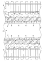
- the notification system 1 includes a sound field generation device 1A and a possession device 1B as shown in FIG.
- the sound field generation device 1A is a device which is disposed outside the possession device 1B and forms a notification area 51 which is a sound field by ultrasonic waves.
- the sound field generation device 1A includes a processing unit 10 and an ultrasonic wave output unit 20.
- the notification area 51 is set to include at least a part of the target area, and in the present embodiment, it is assumed that the notification area 51 matches the target area.
- the possessing device 1B is a device that the subject person possesses and acts, and is configured as, for example, a mobile phone, a smartphone, a wearable computer, or the like.
- the possessing device 1 ⁇ / b> B includes a control unit 30, an ultrasonic detection unit 41, and a notification unit 42.
- the ultrasonic wave output unit 20 includes an ultrasonic wave amplifier 21 and an ultrasonic wave speaker 22.
- the ultrasonic amplifier 21 amplifies the waveform of the signal generated by the processing unit 10 so as to have a preset amplification factor, and outputs the amplified signal from the ultrasonic speaker 22.
- the ultrasonic amplifier 21 may be provided for each ultrasonic speaker 22 or may be provided for a plurality of ultrasonic speakers 22.
- the ultrasonic speaker 22 is an ultrasonic generator that generates an air vibration having a frequency higher than that of human hearing, for example, 20 kHz or more, and is configured as a piezoelectric speaker suitable for ultrasonic wave reproduction, for example.
- Piezoelectric speakers include ceramic speakers, piezo speakers, and the like.
- the ultrasonic speaker 22 is arrange
- An area where the sound wave is output by the ultrasonic speaker 22, that is, an area where the sound wave can be detected by the possession device 1 B is referred to as a notification area 51.
- the notification area 51 shown in FIGS. 2 and 3 is, for example, -6 dB or more with respect to the sound pressure at the center of the direction in which the sound wave is output by the ultrasonic speaker 22, that is, the sound pressure at the sound axis. Indicates an area.
- the plurality of ultrasonic speakers 22 are set such that the area between yellow line 73 such as a Braille block disposed on platform 72 and the end 74 of platform 72 is within notification area 51.
- the plurality of ultrasonic speakers 22 are disposed at substantially equal intervals such that the entire notification area is the notification area 51, with the area between the yellow line 73 and the end 74 of the platform 72 as the notification area.
- the notification areas 51 of the plurality of ultrasonic speakers 22 may be arranged so as to partially overlap each other.
- the target person can be notified. That is, in the notification system 1, the target person himself is in danger of falling before the target person falls from the end 74 of the platform 72 to the travel area 78 of the railway vehicle 80 for the target person who possesses the possessing device 1B. Make them aware of what they are doing.
- the ultrasonic detection unit 41 is configured as a microphone capable of detecting the sound emitted from the ultrasonic speaker 22. It is preferable that the ultrasonic detection unit 41 can detect an ultrasonic wave, but if the sound emitted from the ultrasonic speaker 22 is modulated to an audible sound, it may be configured to be able to detect the audible sound.
- the ultrasonic wave detection unit 41 can adopt, for example, a microphone for voice communication.
- the notification unit 42 has a known configuration for notifying a target person of the possessing device 1B.
- the notification unit 42 can be configured as, for example, a speaker for notification by sound, a light emission unit for notification by light, a vibration unit for notification by vibration, a odor detection unit for notification by odor, or the like.
- the notification unit 42 is configured as a vibrating unit having a known vibrator.
- the processing unit 10 of the sound field generation device 1A and the control unit 30 of the possessing device 1B are each a well-known micro computer having CPUs 11 and 31 and semiconductor memories (hereinafter memories 12 and 32) such as RAM, ROM and flash memory. It is built around a computer.
- memories 12 and 32 semiconductor memories
- Various functions of the processing unit 10 and the control unit 30 are realized by the CPUs 11 and 31 executing programs stored in the non-transitional tangible recording medium.
- the memories 12 and 32 correspond to the non-transitional tangible storage medium storing the program.
- the non-transitional tangible recording medium has a meaning excluding the electromagnetic wave in the recording medium.
- the number of microcomputers constituting the processing unit 10 and the control unit 30 may be one or more.
- the processing unit 10 of the sound field generation device 1A includes a pattern generation unit 16 and a signal generation unit 17 as a configuration of a function realized by the CPU 11 executing a program.
- the control unit 30 of the possessing device 1B includes a filter unit 36, a pattern recognition unit 37, and a notification determination unit 38 as the configuration of functions realized by the CPU 31 executing a program.
- the method for realizing these elements constituting the processing unit 10 and the control unit 30 is not limited to software, and some or all of the elements may be realized using one or more hardware.
- the electronic circuit may be realized by a digital circuit including many logic circuits, an analog circuit, or a combination thereof.
- the function of the pattern generation unit 16 generates a signal pattern for outputting a pattern sound.
- the pattern sound is a sound wave transmitted to the notification area 51, and represents a sound having a specific pattern.
- the signal pattern generated here is a pattern consisting of four cycles of a pattern in which sound is generated for a time of ⁇ T1 and then silence for a time of ⁇ T2 and a silence time of ⁇ T3.
- Adopt a pattern that repeats continuously.
- ⁇ T1 and ⁇ T2 are arbitrarily set according to the resolution of the ultrasonic wave detection unit 41, and for example, ⁇ T1 and ⁇ T2 are each set to about 0.8 to 25 ms.
- ⁇ T3 is, for example, a time equal to or longer than the sum of ⁇ T1 and ⁇ T2, and is set to, for example, about 1.6 to 500 ms.
- the wavelength is shorter than that of the audible sound, so that even if ⁇ T1 and ⁇ T2 are set to be shorter, recognition can be facilitated.
- the function of the signal generation unit 17 generates a pattern sound by modulating the ultrasonic wave to a lower frequency, and outputs the pattern sound to the notification area 51 as a sound having directivity.
- the reason that the function of the signal generation unit 17 generates directional sound is to limit the notification area 51 to an area that is dangerous to the target person and to make it difficult for the notification area 51 to spread to an area that is not dangerous. That is, the notification area 51 is generated by an ultrasonic wave which is a sound having a characteristic that the sound pressure rises sharply as it approaches the sound axis.
- the signal generation unit 17 for example, about 4 kHz that can be detected by the ultrasonic detection unit 41 by amplitude-modulating the waveform of the ultrasonic wave having a predetermined amplitude of about 40 kHz, for example.
- a waveform whose amplitude is changed so as to be a frequency and a signal pattern generated by the pattern generation unit 16 is generated.
- the control unit 30 of the possessing device 1B uses the functions of the filter unit 36, the pattern recognition unit 37, and the notification determination unit 38 to carry out a danger notification process described later.
- the danger notification process executed by the control unit 30 of the possessing device 1B will be described using the flowchart of FIG.
- the danger notification process is a process that is started when a predetermined application related to the danger notification is activated in the possessing device 1B, and then repeatedly performed.
- the control unit 30 uses the function of the filter unit 36 to generate a sound wave corresponding to the modulated frequency output from the ultrasonic speaker 22 from the sound wave detected by the ultrasonic detection unit 41. Extract.
- sound waves are analyzed as software processing, and only sound waves in a predetermined frequency band are extracted. Note that this processing may be realized using known hardware such as a known band pass filter.
- step S120 the control unit 30 recognizes the pattern sound using the function of the pattern recognition unit 37.
- the pattern sound here is a sound wave generated by the pattern generation unit 16 and output from the ultrasonic speaker 22.
- it is determined whether the sound wave of the frequency extracted in S110 detects a sound for a time corresponding to ⁇ T1 and detects N cycles of a pattern in which silent for at least the time corresponding to ⁇ T2 is detected. It recognizes that the pattern sound has been detected when the pattern of has been detected.
- the value of N may be set arbitrarily, but is set to, for example, a value of about 2.
- step S130 the control unit 30 determines whether the pattern sound has been detected using the function of the notification determination unit 38. If the pattern sound can not be detected in S130, the control unit 30 determines that the possessing device 1B is out of the notification area 51, and ends the danger notification process.
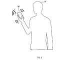
- control unit 30 proceeds to S140, and performs notification to the target person 81 by vibrating the vibrator constituting the notification unit 42 as shown in FIG. .
- the target person 81 wearing the possessing device 1B receives the notification by the notification unit 42, and can therefore recognize that he is in the notification area 51. [1-3. effect] According to the first embodiment described above, the following effects can be obtained.
- the control unit 30 of the possession device 1B detects the pattern sound transmitted by the ultrasonic wave output unit 20.
- pattern sounds have directivity.
- the control unit 30 notifies the subject.
- the target person in the notification area 51 formed of the pattern sound is notified. Therefore, if the unsafe area is set in the notification area 51, the target person in the safe position Can be suppressed and notifications can be given to subjects who are in an unsafe position.
- the sound field generation device 1A generates pattern sound by ultrasonic waves and transmits the pattern sound to the target area via the ultrasonic wave output unit 20.
- control part 30 of possession device 1B is constituted so that a pattern sound transmitted from ultrasonic wave output part 20 may be detected.
- a target region can be set in a narrower range, and a notification formed by this pattern sound Only the possessing device 1B located in the area 51 can be configured to perform the notification.
- the sound field generation device 1A modulates the ultrasonic wave to a lower frequency to form the notification area 51 with pattern sound, and transmit the pattern sound to the target area.
- the control unit 30 of the possession device 1B is configured to detect the pattern sound transmitted by the ultrasonic wave output unit 20.
- the configuration can be made to conform to the frequency of the sound wave receivable by the possession device 1B. .
- control unit 30 of the possessing device 1B is configured to notify the subject by vibrating the vibrator that constitutes the notification unit 42.
- the notification since the notification is given by vibration, the notification should be performed well even when the target person is a visually impaired person or when the target person is positioned in a region where the environmental sound is large. Can.
- the processing unit 10 of the sound field generation device 1A is a function of the pattern generation unit 16 and the signal generation unit 17, and a sound wave signal including pattern sound representing sound of a specific pattern having directivity.
- Configured to generate The ultrasound output unit 20 is configured to output a sound wave based on the sound wave signal to the target area.
- a pattern sound having directivity to the target area is emitted. Therefore, if the pattern sound can be detected in the target area, the target person is positioned in the target area. Can be notified.
- the sound field generation device 1A is disposed on the ceiling 71 of the platform 72, and the target area and the notification area 51 are set at the end of the train station's home.
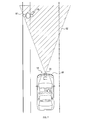
- the sound field generation device 1A is mounted on a vehicle 86 traveling on a road, such as a passenger car, and the target area and the notification area 52 are on the road. It differs from the first embodiment in that it is set.
- the sound field generation device 1A is mounted on a vehicle 86, and the ultrasonic speakers 22 are arranged in the traveling direction on the surface facing the traveling direction of the vehicle 86 Be done.
- the ultrasonic speaker 22 is disposed in front of the vehicle 86 and directed to the front of the vehicle.
- At least one ultrasonic speaker 22 may be disposed.
- the ultrasonic speaker 22 may be disposed toward the rear of the vehicle on the rear surface of the vehicle.
- the processing unit 10 detects the traveling direction of the vehicle and only the ultrasonic speaker 22 on the traveling direction side of the vehicle operates. You may
- a target area is set on the road on the traveling direction side of the vehicle 86, and a notification area 52 as a sound field by the ultrasonic speaker 22 is formed to coincide with the target area. If a target person 87 who possesses the possessing device 1B is present in the notification area 52, the notification can be performed in the same manner as the configuration of the first embodiment.
- the notification area 52 is formed on the traveling direction side of the vehicle 86, so that notification can be made to the target person 87 located on the route of the vehicle 86. Therefore, even when the running noise of the vehicle 86 is small, the target person 87 can be favorably notified that the vehicle 86 approaches.
- the sound wave for changing the strength of the sound pressure is generated, but it is not limited to this.
- the sound field generation device 1A may generate, for example, pattern sound by changing the frequency of sound or pattern sound by synthesis of sounds of a plurality of frequencies. Further, the sound field generation device 1A may generate a pattern sound combining the strength of sound pressure, the change of sound frequency, the synthesis of sounds of a plurality of frequencies, and the like.
- the sound field generation device 1A generates the pattern sound of the audible sound by the ultrasonic modulation, but for example, the pattern sound of the ultrasonic range of 20 kHz or more may be generated. According to such a configuration, since the ultrasonic range is a range which is hard to be included in the environmental sound, it is possible to suppress false detection of the pattern sound.
- the plurality of functions of one component in the above embodiment may be realized by a plurality of components, or one function of one component may be realized by a plurality of components . Also, a plurality of functions possessed by a plurality of components may be realized by one component, or one function realized by a plurality of components may be realized by one component.
- part of the configuration of the above embodiment may be omitted. Further, at least a part of the configuration of the above-described embodiment may be added to or replaced with the configuration of the other above-described embodiment.
- all the aspects contained in the technical thought specified from the wording described in the claim are an embodiment of this indication.
- each device that is a component of the notification system 1 a program for causing a computer to function as the notification system 1, non-transitional substance such as a semiconductor memory recording this program
- non-transitional substance such as a semiconductor memory recording this program
- the present disclosure can also be realized in various forms such as a recording medium and a notification method.
- the sound field generation device 1A corresponds to the sound generation device referred to in the present disclosure
- the possession device 1B corresponds to the notification device referred to in the present disclosure
- the pattern generation unit 16 and the signal generation unit 17 correspond to the sound wave generation unit in the present disclosure
- the ultrasonic wave output unit 20 corresponds to the sound wave output unit and the sound wave transmission unit in the present disclosure.
- the notification part 42 in the said embodiment is corresponded to the vibration part said by this indication.
- the processes of S110 to S140 executed by the control unit 30 in the above embodiment correspond to the notification method in the present disclosure, and in particular, the processes of S110 and S120 correspond to the detection unit in the present disclosure, S130 and S140. Processing corresponds to the notification unit in the present disclosure.
Abstract
This notification method (S110-S140), executed by a possessed device (1B) possessed and carried by a subject, serves to issue a notification indicating that the possessed device is located in a prescribed region (51, 52). In the method, a notification is issued to the subject upon detection of a sound pattern that is transmitted by a soundwave transmission unit (20), wherein the soundwave transmission unit transmits a unique sound pattern for said prescribed region.
Description
本国際出願は、2017年7月25日に日本国特許庁に出願された日本国特許出願第2017-143671号に基づく優先権を主張するものであり、日本国特許出願第2017-143671号の全内容を参照により本国際出願に援用する。
This international application claims priority based on Japanese Patent Application No. 201-143,671 filed on Jul. 25, 2017 to the Japanese Patent Office, and The entire contents are incorporated into this international application by reference.
本開示は、音波を検知して通知する技術に関する。
The present disclosure relates to a technology for detecting and notifying a sound wave.
下記の特許文献1には、歩行者等の対象者によって所持される所持装置が、車両から発せられる音を検知すると通知を行う技術が提案されている。
In Patent Document 1 below, a technique is proposed in which a possessing device possessed by a subject person such as a pedestrian makes a notification when it detects a sound emitted from a vehicle.
発明者の詳細な検討の結果、特許文献1の技術では、安全でない位置にいる対象者に対して通知を行う場合には、通知が有効に機能するが、車両から発せられる音を検知すれば、車両との関係で安全な位置にいる対象者に対しても通知を行うので、この場合の通知が煩わしいという課題が見出された。また、車両以外であっても、安全な位置にいる対象者に対して通知を行う構成は、通知が煩わしいという課題が見出された。
As a result of the inventor's detailed study, in the technique of Patent Document 1, when notifying a target person who is in an unsafe position, the notification functions effectively, but if the sound emitted from the vehicle is detected Since the notification is also given to the target person in a safe position in relation to the vehicle, it has been found that the notification in this case is bothersome. Moreover, the structure which notifies with respect to the object person in a safe position even if it is except a vehicle discovered the subject that notification was troublesome.
本開示の一側面は、安全な位置にいる対象者への通知を抑制し、安全ではない位置にいる対象者に通知する技術を提供することにある。
本開示の一態様の通知方法は、対象者が所持して行動する所持装置が実行し、所持装置が予め設定された対象領域に位置することを通知する通知方法である。 One aspect of the present disclosure is to provide a technology for suppressing notification to a subject in a safe position and notifying a subject in an unsafe position.
The notification method according to an aspect of the present disclosure is a notification method performed by a possessing device that a subject person holds and acts to notify that the possessing device is located in a predetermined target area.
この通知方法において、所持装置は、音波送信部にて送信されたパターン音を検知する。なお、音波送信部は、対象領域に対して特定のパターンの音を表すパターン音を送信するように構成される。また、所持装置は、パターン音を検知すると対象者に対する通知を行う。
In the notification method, the possessing device detects the pattern sound transmitted by the sound wave transmission unit. The sound wave transmission unit is configured to transmit a pattern sound representing a sound of a specific pattern to the target area. In addition, when the possessing device detects a pattern sound, it notifies the target person.
このような通知方法によれば、パターン音によって形成された対象領域にいる対象者に対して通知を行うので、安全でない領域を対象領域に設定すれば、安全な位置にいる対象者への通知を抑制し、安全ではない位置にいる対象者に通知することができる。
According to such a notification method, since notification is given to the target person in the target area formed by the pattern sound, if the unsafe area is set as the target area, the target person in the safe position is notified. Can be controlled and notified to a subject who is in an unsafe position.
なお、請求の範囲に記載した括弧内の符号は、一つの態様として後述する実施形態に記載の具体的手段との対応関係を示すものであって、本開示の技術的範囲を限定するものではない。
In addition, the code in the parentheses described in the claims indicates the correspondence with the specific means described in the embodiment described later as one aspect, and the technical scope of the present disclosure is limited. Absent.
以下、図面を参照しながら、本開示の一態様の実施形態を説明する。
[1.第1実施形態]
[1-1.構成]
図1に示す通知システム1は、対象者が所持して行動する所持装置1Bが予め設定された対象領域内に位置する場合に所持装置1Bが対象者に対して通知を行うシステムである。 Hereinafter, embodiments of one aspect of the present disclosure will be described with reference to the drawings.
[1. First embodiment]
[1-1. Constitution]
Thenotification system 1 illustrated in FIG. 1 is a system in which the possessing device 1B notifies an object person when the possessing device 1B possessed and acted by the object person is located within a predetermined target area.
[1.第1実施形態]
[1-1.構成]
図1に示す通知システム1は、対象者が所持して行動する所持装置1Bが予め設定された対象領域内に位置する場合に所持装置1Bが対象者に対して通知を行うシステムである。 Hereinafter, embodiments of one aspect of the present disclosure will be described with reference to the drawings.
[1. First embodiment]
[1-1. Constitution]
The
ここで、対象者とは、通知の対象となる人物を表す。例えば、対象者には、一般的な歩行者、視覚障碍者等が該当する。また、対象領域とは、対象者にとって危険を及ぼす可能性がある領域、つまり安全でない領域を示す。また、対象領域は、音源に対して特定の方向、角度範囲内のみに設定される。例えば、本実施形態の対象領域は、鉄道駅のプラットホームの端部に設定され、また、音源となるスピーカから下向きの所定の角度範囲内、例えば音軸を中心にその周囲5degの範囲内等に設定される。
Here, the target person represents a person to be notified. For example, general pedestrians, visually impaired persons, etc. correspond to the target person. Also, the target area indicates an area that may pose a danger to the target person, that is, an unsafe area. In addition, the target area is set only within a specific direction and angle range with respect to the sound source. For example, the target area of the present embodiment is set at the end of the platform of the railway station, and within a predetermined angle range downward from the sound source speaker, for example, within the range of 5 deg around the sound axis It is set.
通知システム1は、図1に示すように、音場生成装置1Aと所持装置1Bとを備える。
音場生成装置1Aは、所持装置1Bの外部に配置され、超音波による音場である通知領域51を形成する装置である。音場生成装置1Aは、処理部10と、超音波出力部20とを備える。なお、通知領域51は、対象領域の少なくとも一部を含むように設定され、本実施形態では、通知領域51と対象領域とが一致すると仮定して説明する。 Thenotification system 1 includes a sound field generation device 1A and a possession device 1B as shown in FIG.
The soundfield generation device 1A is a device which is disposed outside the possession device 1B and forms a notification area 51 which is a sound field by ultrasonic waves. The sound field generation device 1A includes a processing unit 10 and an ultrasonic wave output unit 20. Note that the notification area 51 is set to include at least a part of the target area, and in the present embodiment, it is assumed that the notification area 51 matches the target area.
音場生成装置1Aは、所持装置1Bの外部に配置され、超音波による音場である通知領域51を形成する装置である。音場生成装置1Aは、処理部10と、超音波出力部20とを備える。なお、通知領域51は、対象領域の少なくとも一部を含むように設定され、本実施形態では、通知領域51と対象領域とが一致すると仮定して説明する。 The
The sound
所持装置1Bは、対象者が所持して行動する装置であり、例えば、携帯電話機、スマートフォン、ウェアラブルコンピュータ(wearable computer)等として構成される。所持装置1Bは、制御部30と、超音波検知部41と、通知部42とを備える。
The possessing device 1B is a device that the subject person possesses and acts, and is configured as, for example, a mobile phone, a smartphone, a wearable computer, or the like. The possessing device 1 </ b> B includes a control unit 30, an ultrasonic detection unit 41, and a notification unit 42.
音場生成装置1Aにおいて、超音波出力部20は、超音波アンプ21と、超音波スピーカ22とを備える。
超音波アンプ21は、処理部10にて生成された信号の波形を予め設定された増幅率となるように増幅して、超音波スピーカ22から出力する。なお、超音波アンプ21は、超音波スピーカ22毎に設けられてもよいし、複数の超音波スピーカ22に対して設けられてもよい。 In the soundfield generation device 1A, the ultrasonic wave output unit 20 includes an ultrasonic wave amplifier 21 and an ultrasonic wave speaker 22.
Theultrasonic amplifier 21 amplifies the waveform of the signal generated by the processing unit 10 so as to have a preset amplification factor, and outputs the amplified signal from the ultrasonic speaker 22. The ultrasonic amplifier 21 may be provided for each ultrasonic speaker 22 or may be provided for a plurality of ultrasonic speakers 22.
超音波アンプ21は、処理部10にて生成された信号の波形を予め設定された増幅率となるように増幅して、超音波スピーカ22から出力する。なお、超音波アンプ21は、超音波スピーカ22毎に設けられてもよいし、複数の超音波スピーカ22に対して設けられてもよい。 In the sound
The
超音波スピーカ22は、人間の可聴帯域よりも高い、例えば20kHz以上の周波数の空気振動を発生させる超音波発生器であり、例えば、超音波再生に適した圧電スピーカとして構成されている。圧電スピーカには、セラミックスピーカ、ピエゾスピーカ等が含まれる。
The ultrasonic speaker 22 is an ultrasonic generator that generates an air vibration having a frequency higher than that of human hearing, for example, 20 kHz or more, and is configured as a piezoelectric speaker suitable for ultrasonic wave reproduction, for example. Piezoelectric speakers include ceramic speakers, piezo speakers, and the like.
超音波スピーカ22は、図2、図3に示すように、鉄道駅のプラットホーム72の天井71において、鉄道車両80の進行方向に沿って並べて配置される。超音波スピーカ22による音波が出力される領域、つまり所持装置1Bによって音波を検知しうる領域を通知領域51と呼ぶ。なお、図2および図3にて示す通知領域51は、超音波スピーカ22によって音波が出力される方向の中心での音圧、つまり音軸での音圧に対して、例えば-6dB以上となる領域を示す。
The ultrasonic speaker 22 is arrange | positioned along with the advancing direction of the rail vehicle 80 in the ceiling 71 of the platform 72 of a railway station, as shown to FIG. 2, FIG. An area where the sound wave is output by the ultrasonic speaker 22, that is, an area where the sound wave can be detected by the possession device 1 B is referred to as a notification area 51. The notification area 51 shown in FIGS. 2 and 3 is, for example, -6 dB or more with respect to the sound pressure at the center of the direction in which the sound wave is output by the ultrasonic speaker 22, that is, the sound pressure at the sound axis. Indicates an area.
複数の超音波スピーカ22は、それぞれ、プラットホーム72に配置された点字ブロック等の黄線73とプラットホーム72の端部74との間の領域が、通知領域51内になるよう設定される。複数の超音波スピーカ22は、黄線73およびプラットホーム72の端部74の間の領域を通知領域として、この通知領域の全域が通知領域51となるように、概ね等間隔で配置される。複数の超音波スピーカ22による通知領域51は、互いに一部が重なるように配置されてもよい。
The plurality of ultrasonic speakers 22 are set such that the area between yellow line 73 such as a Braille block disposed on platform 72 and the end 74 of platform 72 is within notification area 51. The plurality of ultrasonic speakers 22 are disposed at substantially equal intervals such that the entire notification area is the notification area 51, with the area between the yellow line 73 and the end 74 of the platform 72 as the notification area. The notification areas 51 of the plurality of ultrasonic speakers 22 may be arranged so as to partially overlap each other.
このように通知領域51を設定することで、所持装置1Bがプラットホーム72の端部74に近づくと、対象者に通知を行う構成にすることができる。つまり、通知システム1は、所持装置1Bを所持する対象者に対して、対象者がプラットホーム72の端部74から鉄道車両80の走行領域78に転落する前に、対象者自身に転落の危険が及んでいることを察知させる。
By setting the notification area 51 in this manner, when the possessing device 1B approaches the end 74 of the platform 72, the target person can be notified. That is, in the notification system 1, the target person himself is in danger of falling before the target person falls from the end 74 of the platform 72 to the travel area 78 of the railway vehicle 80 for the target person who possesses the possessing device 1B. Make them aware of what they are doing.
所持装置1Bにおいて、超音波検知部41は、超音波スピーカ22から発せられる音を検知可能なマイクとして構成される。超音波検知部41は、超音波を検知できることが好ましいが、超音波スピーカ22から発せられる音が可聴音に変調されている場合には、この可聴音を検知できる構成であればよい。超音波検知部41は、例えば、音声通話用のマイクを採用することができる。
In the possessing device 1B, the ultrasonic detection unit 41 is configured as a microphone capable of detecting the sound emitted from the ultrasonic speaker 22. It is preferable that the ultrasonic detection unit 41 can detect an ultrasonic wave, but if the sound emitted from the ultrasonic speaker 22 is modulated to an audible sound, it may be configured to be able to detect the audible sound. The ultrasonic wave detection unit 41 can adopt, for example, a microphone for voice communication.
通知部42は、所持装置1Bの対象者に対する通知を行う周知の構成を備える。通知部42は、例えば、音によって通知を行うためのスピーカ、光によって通知を行う発光部、振動によって通知を行う振動部、臭いによって通知を行う発臭部等として構成することができる。特に、本実施形態では、通知部42は、周知のバイブレータを有する振動部として構成される。
The notification unit 42 has a known configuration for notifying a target person of the possessing device 1B. The notification unit 42 can be configured as, for example, a speaker for notification by sound, a light emission unit for notification by light, a vibration unit for notification by vibration, a odor detection unit for notification by odor, or the like. In particular, in the present embodiment, the notification unit 42 is configured as a vibrating unit having a known vibrator.
音場生成装置1Aの処理部10および所持装置1Bの制御部30は、それぞれCPU11,31と、RAM、ROM、フラッシュメモリ等の半導体メモリ(以下、メモリ12,32)と、を有する周知のマイクロコンピュータを中心に構成される。処理部10および制御部30の各種機能は、CPU11,31が非遷移的実体的記録媒体に格納されたプログラムを実行することにより実現される。この例では、メモリ12,32が、プログラムを格納した非遷移的実体的記録媒体に該当する。
The processing unit 10 of the sound field generation device 1A and the control unit 30 of the possessing device 1B are each a well-known micro computer having CPUs 11 and 31 and semiconductor memories (hereinafter memories 12 and 32) such as RAM, ROM and flash memory. It is built around a computer. Various functions of the processing unit 10 and the control unit 30 are realized by the CPUs 11 and 31 executing programs stored in the non-transitional tangible recording medium. In this example, the memories 12 and 32 correspond to the non-transitional tangible storage medium storing the program.
また、このプログラムが実行されることで、プログラムに対応する方法が実行される。なお、非遷移的実体的記録媒体とは、記録媒体のうちの電磁波を除く意味である。また、処理部10および制御部30を構成するマイクロコンピュータの数は1つでも複数でもよい。
Also, by executing this program, a method corresponding to the program is executed. Note that the non-transitional tangible recording medium has a meaning excluding the electromagnetic wave in the recording medium. Further, the number of microcomputers constituting the processing unit 10 and the control unit 30 may be one or more.
音場生成装置1Aの処理部10は、CPU11がプログラムを実行することで実現される機能の構成として、パターン生成部16と、信号生成部17と、を備える。一方、所持装置1Bの制御部30は、CPU31がプログラムを実行することで実現される機能の構成として、フィルタ部36と、パターン認識部37と、通知判定部38とを備える。
The processing unit 10 of the sound field generation device 1A includes a pattern generation unit 16 and a signal generation unit 17 as a configuration of a function realized by the CPU 11 executing a program. On the other hand, the control unit 30 of the possessing device 1B includes a filter unit 36, a pattern recognition unit 37, and a notification determination unit 38 as the configuration of functions realized by the CPU 31 executing a program.
処理部10および制御部30を構成するこれらの要素を実現する手法はソフトウェアに限るものではなく、その一部または全部の要素について、一つあるいは複数のハードウェアを用いて実現してもよい。例えば、上記機能がハードウェアである電子回路によって実現される場合、その電子回路は多数の論理回路を含むデジタル回路、またはアナログ回路、あるいはこれらの組合せによって実現してもよい。
The method for realizing these elements constituting the processing unit 10 and the control unit 30 is not limited to software, and some or all of the elements may be realized using one or more hardware. For example, when the above function is realized by an electronic circuit that is hardware, the electronic circuit may be realized by a digital circuit including many logic circuits, an analog circuit, or a combination thereof.
音場生成装置1Aの処理部10において、パターン生成部16の機能では、パターン音を出力するための信号パターンを生成する。パターン音とは、通知領域51に対して送信される音波であって、特定のパターンを有する音を表す。
In the processing unit 10 of the sound field generation device 1A, the function of the pattern generation unit 16 generates a signal pattern for outputting a pattern sound. The pattern sound is a sound wave transmitted to the notification area 51, and represents a sound having a specific pattern.
ここで生成される信号パターンは、例えば図4に示すように、ΔT1の時間だけ発音し、その後、ΔT2の時間だけ無音となるパターンを4周期分と、ΔT3の無音時間とをからなるパターンを連続的に繰り返すパターンを採用する。
For example, as shown in FIG. 4, the signal pattern generated here is a pattern consisting of four cycles of a pattern in which sound is generated for a time of ΔT1 and then silence for a time of ΔT2 and a silence time of ΔT3. Adopt a pattern that repeats continuously.
なお、ΔT1、ΔT2は、超音波検知部41の分解能に応じて任意に設定され、例えば、ΔT1、ΔT2は、それぞれ0.8~25ms程度に設定される。また、ΔT3は、例えば、ΔT1とΔT2との和以上の時間であって、例えば、1.6~500ms程度に設定される。
Note that ΔT1 and ΔT2 are arbitrarily set according to the resolution of the ultrasonic wave detection unit 41, and for example, ΔT1 and ΔT2 are each set to about 0.8 to 25 ms. Further, ΔT3 is, for example, a time equal to or longer than the sum of ΔT1 and ΔT2, and is set to, for example, about 1.6 to 500 ms.
超音波を用いる構成では、可聴音に対して波長が短いので、ΔT1、ΔT2をより短時間に設定しても、良好に認識しやすくすることができる。
信号生成部17の機能では、超音波をより低い周波数に変調することによってパターン音を生成し、指向性を有する音として通知領域51に出力する。信号生成部17の機能が指向性を有する音を生成するのは、通知領域51を対象者にとって危険となる領域に限定し、危険とならない領域に通知領域51が広がりにくくするためである。つまり、音軸に近づくと急激に音圧が上がる特性を有する音である超音波で通知領域51を生成する。 In the configuration using ultrasonic waves, the wavelength is shorter than that of the audible sound, so that even if ΔT1 and ΔT2 are set to be shorter, recognition can be facilitated.
The function of thesignal generation unit 17 generates a pattern sound by modulating the ultrasonic wave to a lower frequency, and outputs the pattern sound to the notification area 51 as a sound having directivity. The reason that the function of the signal generation unit 17 generates directional sound is to limit the notification area 51 to an area that is dangerous to the target person and to make it difficult for the notification area 51 to spread to an area that is not dangerous. That is, the notification area 51 is generated by an ultrasonic wave which is a sound having a characteristic that the sound pressure rises sharply as it approaches the sound axis.
信号生成部17の機能では、超音波をより低い周波数に変調することによってパターン音を生成し、指向性を有する音として通知領域51に出力する。信号生成部17の機能が指向性を有する音を生成するのは、通知領域51を対象者にとって危険となる領域に限定し、危険とならない領域に通知領域51が広がりにくくするためである。つまり、音軸に近づくと急激に音圧が上がる特性を有する音である超音波で通知領域51を生成する。 In the configuration using ultrasonic waves, the wavelength is shorter than that of the audible sound, so that even if ΔT1 and ΔT2 are set to be shorter, recognition can be facilitated.
The function of the
具体的には、信号生成部17の機能では、例えば40kHz程度の所定の周波数を有する振幅一定の超音波の波形を、振幅変調することによって、超音波検知部41が検知可能な例えば4kHz程度の周波数であって、かつパターン生成部16にて生成された信号パターンとなるように、振幅が変更された波形を生成する。なお、この波形を生成するためには、振幅一定の超音波の波形を目標とする周波数に振幅変調した後、信号パターンと一致するよう出力レベルを変更するとよい。
Specifically, in the function of the signal generation unit 17, for example, about 4 kHz that can be detected by the ultrasonic detection unit 41 by amplitude-modulating the waveform of the ultrasonic wave having a predetermined amplitude of about 40 kHz, for example. A waveform whose amplitude is changed so as to be a frequency and a signal pattern generated by the pattern generation unit 16 is generated. In addition, in order to generate this waveform, it is preferable to amplitude-modulate the waveform of the ultrasonic wave having a constant amplitude to a target frequency and then change the output level to match the signal pattern.
なお、所持装置1Bの制御部30は、フィルタ部36、パターン認識部37、通知判定部38の各機能を用いて、後述する危険通知処理を実施する。
[1-2.処理]
次に、所持装置1Bの制御部30が実行する危険通知処理について、図5のフローチャートを用いて説明する。危険通知処理は、所持装置1Bにおいて危険通知に関する所定のアプリケーションが起動されると開始され、その後、繰り返し実施される処理である。 Note that thecontrol unit 30 of the possessing device 1B uses the functions of the filter unit 36, the pattern recognition unit 37, and the notification determination unit 38 to carry out a danger notification process described later.
[1-2. processing]
Next, the danger notification process executed by thecontrol unit 30 of the possessing device 1B will be described using the flowchart of FIG. The danger notification process is a process that is started when a predetermined application related to the danger notification is activated in the possessing device 1B, and then repeatedly performed.
[1-2.処理]
次に、所持装置1Bの制御部30が実行する危険通知処理について、図5のフローチャートを用いて説明する。危険通知処理は、所持装置1Bにおいて危険通知に関する所定のアプリケーションが起動されると開始され、その後、繰り返し実施される処理である。 Note that the
[1-2. processing]
Next, the danger notification process executed by the
危険通知処理では、まず、S110で、制御部30はフィルタ部36の機能を用いて、超音波検知部41が検知した音波から、超音波スピーカ22が出力した変調後の周波数に対応する音波を抽出する。この処理では、ソフトウェアの処理として音波を解析し、所定の周波数帯の音波のみを抽出する。なお、周知のバンドパスフィルタ等の周知のハードウェアを用いて本処理を実現してもよい。
In the danger notification process, first, in S110, the control unit 30 uses the function of the filter unit 36 to generate a sound wave corresponding to the modulated frequency output from the ultrasonic speaker 22 from the sound wave detected by the ultrasonic detection unit 41. Extract. In this process, sound waves are analyzed as software processing, and only sound waves in a predetermined frequency band are extracted. Note that this processing may be realized using known hardware such as a known band pass filter.
続いて、制御部30は、S120で、パターン認識部37の機能を用いて、パターン音を認識する。ここでのパターン音は、パターン生成部16にて生成され、超音波スピーカ22から出力された音波である。この処理では、S110で抽出された周波数の音波が、ΔT1に対応する時間だけ音を検知し、ΔT2に対応する時間以上無音となるパターンがN周期分検知できたかどうかを判定し、N周期分のパターンが検知できている場合にパターン音が検知できたと認識する。ここで、Nの値は、任意に設定されうるが、例えば、2程度の値に設定される。
Subsequently, in step S120, the control unit 30 recognizes the pattern sound using the function of the pattern recognition unit 37. The pattern sound here is a sound wave generated by the pattern generation unit 16 and output from the ultrasonic speaker 22. In this process, it is determined whether the sound wave of the frequency extracted in S110 detects a sound for a time corresponding to ΔT1 and detects N cycles of a pattern in which silent for at least the time corresponding to ΔT2 is detected. It recognizes that the pattern sound has been detected when the pattern of has been detected. Here, the value of N may be set arbitrarily, but is set to, for example, a value of about 2.
続いて、制御部30は、S130で、通知判定部38の機能を用いて、パターン音を検知できたか否かを判定する。制御部30は、S130で、パターン音を検知できていなければ、所持装置1Bが通知領域51外にいると判定して危険通知処理を終了する。
Subsequently, in step S130, the control unit 30 determines whether the pattern sound has been detected using the function of the notification determination unit 38. If the pattern sound can not be detected in S130, the control unit 30 determines that the possessing device 1B is out of the notification area 51, and ends the danger notification process.
一方、制御部30は、S130で、パターン音を検知できていれば、S140に移行し、図6に示すように、通知部42を構成するバイブレータを振動させることによって対象者81に対する通知を行う。
On the other hand, if the pattern sound can be detected in S130, the control unit 30 proceeds to S140, and performs notification to the target person 81 by vibrating the vibrator constituting the notification unit 42 as shown in FIG. .
所持装置1Bを身に付けている対象者81は、通知部42によって通知を受けるので、自身が通知領域51内にいることを認知することができる。
[1-3.効果]
以上詳述した第1実施形態によれば、以下の効果を奏する。 Thetarget person 81 wearing the possessing device 1B receives the notification by the notification unit 42, and can therefore recognize that he is in the notification area 51.
[1-3. effect]
According to the first embodiment described above, the following effects can be obtained.
[1-3.効果]
以上詳述した第1実施形態によれば、以下の効果を奏する。 The
[1-3. effect]
According to the first embodiment described above, the following effects can be obtained.
(1a)上記の通知システム1において、所持装置1Bの制御部30は、超音波出力部20にて送信されたパターン音を検知する。特に、パターン音は指向性を有する。制御部30は、パターン音を検知すると対象者に対する通知を行う。
(1a) In the notification system 1 described above, the control unit 30 of the possession device 1B detects the pattern sound transmitted by the ultrasonic wave output unit 20. In particular, pattern sounds have directivity. When detecting the pattern sound, the control unit 30 notifies the subject.
このような通知システム1によれば、パターン音によって形成された通知領域51にいる対象者に対して通知を行うので、安全でない領域を通知領域51に設定すれば、安全な位置にいる対象者への通知を抑制し、安全ではない位置にいる対象者に通知することができる。
According to such a notification system 1, the target person in the notification area 51 formed of the pattern sound is notified. Therefore, if the unsafe area is set in the notification area 51, the target person in the safe position Can be suppressed and notifications can be given to subjects who are in an unsafe position.
(1b)上記の通知システム1において音場生成装置1Aは、超音波によってパターン音を生成して超音波出力部20を介して対象領域に送信する。そして、所持装置1Bの制御部30は、超音波出力部20から送信されたパターン音を検知するように構成される。
(1b) In the notification system 1 described above, the sound field generation device 1A generates pattern sound by ultrasonic waves and transmits the pattern sound to the target area via the ultrasonic wave output unit 20. And control part 30 of possession device 1B is constituted so that a pattern sound transmitted from ultrasonic wave output part 20 may be detected.
このような通知システム1によれば、指向性を有する音波、例えば超音波によって生成されたパターン音を用いるので、対象領域をより狭い範囲に設定することができ、このパターン音で形成される通知領域51内に位置する所持装置1Bだけが通知を行う構成にすることができる。
According to such a notification system 1, since a sound wave having directivity, for example, a pattern sound generated by an ultrasonic wave is used, a target region can be set in a narrower range, and a notification formed by this pattern sound Only the possessing device 1B located in the area 51 can be configured to perform the notification.
(1c)上記の通知システム1において音場生成装置1Aは、超音波をより低い周波数に変調することによってパターン音で通知領域51を形成し、パターン音を対象領域に送信する。そして、所持装置1Bの制御部30は、超音波出力部20にて送信されたパターン音を検知するように構成される。
(1c) In the notification system 1 described above, the sound field generation device 1A modulates the ultrasonic wave to a lower frequency to form the notification area 51 with pattern sound, and transmit the pattern sound to the target area. The control unit 30 of the possession device 1B is configured to detect the pattern sound transmitted by the ultrasonic wave output unit 20.
このような通知システム1によれば、超音波をより低い周波数に変調した音波を用いてパターン音が生成されるため、所持装置1Bが受信可能な音波の周波数に適合させる構成にすることができる。
According to such a notification system 1, since the pattern sound is generated using the sound wave in which the ultrasonic wave is modulated to a lower frequency, the configuration can be made to conform to the frequency of the sound wave receivable by the possession device 1B. .
(1d)上記の通知システム1において所持装置1Bの制御部30は、通知部42を構成するバイブレータを振動させることによって対象者に対する通知を行うように構成される。
(1d) In the notification system 1 described above, the control unit 30 of the possessing device 1B is configured to notify the subject by vibrating the vibrator that constitutes the notification unit 42.
このような通知システム1によれば、振動によって通知を行うので、対象者が視覚障碍者である場合や環境音が大きな領域に対象者が位置する場合であっても、良好に通知を行うことができる。
According to such a notification system 1, since the notification is given by vibration, the notification should be performed well even when the target person is a visually impaired person or when the target person is positioned in a region where the environmental sound is large. Can.
(1e)上記の通知システム1において音場生成装置1Aの処理部10は、パターン生成部16および信号生成部17の機能で、指向性を有する特定のパターンの音を表すパターン音を含む音波信号を生成するように構成される。超音波出力部20は、対象領域に対して音波信号に基づく音波を出力するように構成される。
(1e) In the notification system 1 described above, the processing unit 10 of the sound field generation device 1A is a function of the pattern generation unit 16 and the signal generation unit 17, and a sound wave signal including pattern sound representing sound of a specific pattern having directivity. Configured to generate The ultrasound output unit 20 is configured to output a sound wave based on the sound wave signal to the target area.
このような通知システム1によれば、対象領域に対して指向性を有するパターン音を発するので、対象領域内にてこのパターン音を検知できるようにすれば、対象者が対象領域内に位置することを通知することができる。
According to such a notification system 1, a pattern sound having directivity to the target area is emitted. Therefore, if the pattern sound can be detected in the target area, the target person is positioned in the target area. Can be notified.
[2.第2実施形態]
[2-1.第1実施形態との相違点]
第2実施形態は、基本的な構成は第1実施形態と同様であるため、相違点について以下に説明する。なお、第1実施形態と同じ符号は、同一の構成を示すものであって、先行する説明を参照する。 [2. Second embodiment]
[2-1. Differences from the First Embodiment]
The basic configuration of the second embodiment is the same as that of the first embodiment, so the difference will be described below. The same reference numerals as those in the first embodiment denote the same components, and reference is made to the preceding description.
前述した第1実施形態の通知システム1では、音場生成装置1Aはプラットホーム72の天井71に配置され、対象領域および通知領域51が鉄道駅のホームの端部に設定された。これに対し、第2実施形態の通知システム2では、図7に示すように、音場生成装置1Aが乗用車等の道路を走行する車両86に搭載され、対象領域および通知領域52が道路上に設定される点で、第1実施形態と相違する。
In the notification system 1 of the first embodiment described above, the sound field generation device 1A is disposed on the ceiling 71 of the platform 72, and the target area and the notification area 51 are set at the end of the train station's home. On the other hand, in the notification system 2 of the second embodiment, as shown in FIG. 7, the sound field generation device 1A is mounted on a vehicle 86 traveling on a road, such as a passenger car, and the target area and the notification area 52 are on the road. It differs from the first embodiment in that it is set.
[2-2.構成]
第2実施形態の通知システム2では、図7に示すように、音場生成装置1Aは車両86に搭載され、超音波スピーカ22は、車両86の進行方向を向く面において進行方向に向けて配置される。特に本実施形態では、超音波スピーカ22は、車両86の前面にて車両前方に向けて配置される。 [2-2. Constitution]
In the notification system 2 of the second embodiment, as shown in FIG. 7, the soundfield generation device 1A is mounted on a vehicle 86, and the ultrasonic speakers 22 are arranged in the traveling direction on the surface facing the traveling direction of the vehicle 86 Be done. In particular, in the present embodiment, the ultrasonic speaker 22 is disposed in front of the vehicle 86 and directed to the front of the vehicle.
第2実施形態の通知システム2では、図7に示すように、音場生成装置1Aは車両86に搭載され、超音波スピーカ22は、車両86の進行方向を向く面において進行方向に向けて配置される。特に本実施形態では、超音波スピーカ22は、車両86の前面にて車両前方に向けて配置される。 [2-2. Constitution]
In the notification system 2 of the second embodiment, as shown in FIG. 7, the sound
なお、超音波スピーカ22は、少なくとも1つ配置されていればよい。また、超音波スピーカ22は、車両の後面にて車両後方に向けて配置されていてもよい。前面側の超音波スピーカ22と後面側の超音波スピーカ22とを配置する場合には、処理部10が車両の進行方向を検知し、車両の進行方向側の超音波スピーカ22のみが作動するようにしてもよい。
Note that at least one ultrasonic speaker 22 may be disposed. In addition, the ultrasonic speaker 22 may be disposed toward the rear of the vehicle on the rear surface of the vehicle. When arranging the ultrasonic speaker 22 on the front side and the ultrasonic speaker 22 on the rear side, the processing unit 10 detects the traveling direction of the vehicle and only the ultrasonic speaker 22 on the traveling direction side of the vehicle operates. You may
本実施形態の構成では、車両86の進行方向側の道路上に対象領域が設定され、この対象領域と一致するように、超音波スピーカ22による音場としての通知領域52が形成される。この通知領域52内に所持装置1Bを所持する対象者87が存在すれば、第1実施形態の構成と同様に通知を行うことができる。
In the configuration of the present embodiment, a target area is set on the road on the traveling direction side of the vehicle 86, and a notification area 52 as a sound field by the ultrasonic speaker 22 is formed to coincide with the target area. If a target person 87 who possesses the possessing device 1B is present in the notification area 52, the notification can be performed in the same manner as the configuration of the first embodiment.
なお、音場生成装置1Aおよび所持装置1Bが実行する処理については第1実施形態の通知システム1と同様の処理を採用することができる。
[2-3.効果]
以上詳述した第2実施形態によれば、前述した第1実施形態の効果(1a)を奏し、さらに、以下の効果を奏する。 In addition, about the process which sound field production |generation apparatus 1A and possession device 1B perform, the process similar to the notification system 1 of 1st Embodiment is employable.
[2-3. effect]
According to the second embodiment described above, the effect (1a) of the first embodiment described above is exhibited, and further, the following effect is exhibited.
[2-3.効果]
以上詳述した第2実施形態によれば、前述した第1実施形態の効果(1a)を奏し、さらに、以下の効果を奏する。 In addition, about the process which sound field production |
[2-3. effect]
According to the second embodiment described above, the effect (1a) of the first embodiment described above is exhibited, and further, the following effect is exhibited.
(2a)第2実施形態の通知システム2では、車両86の進行方向側に通知領域52が形成されるので、車両86の進路上に位置する対象者87に対する通知を行うことができる。よって、車両86の走行音が小さい場合であっても、車両86が接近することを良好に対象者87に通知することができる。
(2a) In the notification system 2 of the second embodiment, the notification area 52 is formed on the traveling direction side of the vehicle 86, so that notification can be made to the target person 87 located on the route of the vehicle 86. Therefore, even when the running noise of the vehicle 86 is small, the target person 87 can be favorably notified that the vehicle 86 approaches.
[3.他の実施形態]
以上、本開示の実施形態について説明したが、本開示は上述の実施形態に限定されることなく、種々変形して実施することができる。 [3. Other embodiments]
As mentioned above, although embodiment of this indication was described, this indication can be variously deformed and implemented, without being limited to the above-mentioned embodiment.
以上、本開示の実施形態について説明したが、本開示は上述の実施形態に限定されることなく、種々変形して実施することができる。 [3. Other embodiments]
As mentioned above, although embodiment of this indication was described, this indication can be variously deformed and implemented, without being limited to the above-mentioned embodiment.
(3a)上記実施形態では、音場生成装置1Aが生成するパターン音として、音圧の強弱を変化させる音波を生成したが、これに限定されるものではない。音場生成装置1Aは、例えば、音の周波数を変化させることによるパターン音や、複数の周波数の音の合成によるパターン音を生成してもよい。また、音場生成装置1Aは、音圧の強弱、音の周波数の変化、複数の周波数の音の合成、等を組み合わせたパターン音を生成してもよい。
(3a) In the above embodiment, as the pattern sound generated by the sound field generation device 1A, the sound wave for changing the strength of the sound pressure is generated, but it is not limited to this. The sound field generation device 1A may generate, for example, pattern sound by changing the frequency of sound or pattern sound by synthesis of sounds of a plurality of frequencies. Further, the sound field generation device 1A may generate a pattern sound combining the strength of sound pressure, the change of sound frequency, the synthesis of sounds of a plurality of frequencies, and the like.
(3b)上記実施形態では、音場生成装置1Aが超音波変調によって可聴音のパターン音を生成したが、例えば、20kHz以上の超音波音域のパターン音を生成してもよい。
このような構成によれば、超音波音域が環境音に含まれにくい音域であるため、パターン音の誤検知を抑制することができる。 (3b) In the above embodiment, the soundfield generation device 1A generates the pattern sound of the audible sound by the ultrasonic modulation, but for example, the pattern sound of the ultrasonic range of 20 kHz or more may be generated.
According to such a configuration, since the ultrasonic range is a range which is hard to be included in the environmental sound, it is possible to suppress false detection of the pattern sound.
このような構成によれば、超音波音域が環境音に含まれにくい音域であるため、パターン音の誤検知を抑制することができる。 (3b) In the above embodiment, the sound
According to such a configuration, since the ultrasonic range is a range which is hard to be included in the environmental sound, it is possible to suppress false detection of the pattern sound.
(3c)上記実施形態における1つの構成要素が有する複数の機能を、複数の構成要素によって実現したり、1つの構成要素が有する1つの機能を、複数の構成要素によって実現したりしてもよい。また、複数の構成要素が有する複数の機能を、1つの構成要素によって実現したり、複数の構成要素によって実現される1つの機能を、1つの構成要素によって実現したりしてもよい。また、上記実施形態の構成の一部を省略してもよい。また、上記実施形態の構成の少なくとも一部を、他の上記実施形態の構成に対して付加または置換してもよい。なお、請求の範囲に記載した文言から特定される技術思想に含まれるあらゆる態様が本開示の実施形態である。
(3c) The plurality of functions of one component in the above embodiment may be realized by a plurality of components, or one function of one component may be realized by a plurality of components . Also, a plurality of functions possessed by a plurality of components may be realized by one component, or one function realized by a plurality of components may be realized by one component. In addition, part of the configuration of the above embodiment may be omitted. Further, at least a part of the configuration of the above-described embodiment may be added to or replaced with the configuration of the other above-described embodiment. In addition, all the aspects contained in the technical thought specified from the wording described in the claim are an embodiment of this indication.
(3d)上述した通知システム1の他、当該通知システム1の構成要素となる各装置、当該通知システム1としてコンピュータを機能させるためのプログラム、このプログラムを記録した半導体メモリ等の非遷移的実態的記録媒体、通知方法など、種々の形態で本開示を実現することもできる。
(3d) In addition to the notification system 1 described above, each device that is a component of the notification system 1, a program for causing a computer to function as the notification system 1, non-transitional substance such as a semiconductor memory recording this program The present disclosure can also be realized in various forms such as a recording medium and a notification method.
[4.実施形態の構成と本開示の構成との対応関係]
上記実施形態において音場生成装置1Aは本開示でいう発音装置に相当し、所持装置1Bは本開示でいう通知装置に相当する。また、上記実施形態においてパターン生成部16、信号生成部17は本開示でいう音波生成部に相当し、超音波出力部20は本開示でいう音波出力部および音波送信部に相当する。 [4. Correspondence between the configuration of the embodiment and the configuration of the present disclosure]
In the above embodiment, the soundfield generation device 1A corresponds to the sound generation device referred to in the present disclosure, and the possession device 1B corresponds to the notification device referred to in the present disclosure. Further, in the above embodiment, the pattern generation unit 16 and the signal generation unit 17 correspond to the sound wave generation unit in the present disclosure, and the ultrasonic wave output unit 20 corresponds to the sound wave output unit and the sound wave transmission unit in the present disclosure.
上記実施形態において音場生成装置1Aは本開示でいう発音装置に相当し、所持装置1Bは本開示でいう通知装置に相当する。また、上記実施形態においてパターン生成部16、信号生成部17は本開示でいう音波生成部に相当し、超音波出力部20は本開示でいう音波出力部および音波送信部に相当する。 [4. Correspondence between the configuration of the embodiment and the configuration of the present disclosure]
In the above embodiment, the sound
また、上記実施形態において通知部42は本開示でいう振動部に相当する。また、上記実施形態において制御部30が実行するS110~S140の処理は、本開示でいう通知方法に相当し、特に、S110,S120の処理は本開示でいう検知部に相当し、S130,S140の処理は本開示でいう通知部に相当する。
Moreover, the notification part 42 in the said embodiment is corresponded to the vibration part said by this indication. Further, the processes of S110 to S140 executed by the control unit 30 in the above embodiment correspond to the notification method in the present disclosure, and in particular, the processes of S110 and S120 correspond to the detection unit in the present disclosure, S130 and S140. Processing corresponds to the notification unit in the present disclosure.
Claims (6)
- 対象者が所持して行動する所持装置(1B)が実行し、前記所持装置が予め設定された対象領域(51,52)に位置することを通知する通知方法(S110~S140)であって、
前記対象領域に対して特定のパターンの音を表すパターン音を送信する音波送信部(20)にて送信された前記パターン音を検知し(S110,S120)、
前記パターン音を検知すると前記対象者に対する通知を行う(S130,S140)、
通知方法。 A notification method (S110 to S140) for notifying that a target person holds and acts and which is possessed by the possessing device (1B) and which indicates that the possessed device is located in a preset target area (51, 52),
The pattern sound transmitted by the sound wave transmission unit (20) for transmitting a pattern sound representing a sound of a specific pattern to the target area is detected (S110, S120).
When the pattern sound is detected, the target person is notified (S130, S140).
Notification method. - 請求項1に記載の通知方法であって、
前記パターン音を検知する際には、超音波によって前記パターン音を生成して前記対象領域に送信する音波送信部にて送信された前記パターン音を検知する
通知方法。 The notification method according to claim 1, wherein
When detecting the pattern sound, a notification method of detecting the pattern sound transmitted by a sound wave transmitting unit that generates the pattern sound by an ultrasonic wave and transmits the pattern sound to the target area. - 請求項2に記載の通知方法であって、
前記パターン音を検知する際には、超音波をより低い周波数に変調することによって前記パターン音を生成して前記対象領域に送信する音波送信部にて送信された前記パターン音を検知する
通知方法。 The notification method according to claim 2, wherein
When detecting the pattern sound, the pattern sound is generated by modulating an ultrasonic wave to a lower frequency and the pattern sound transmitted by the sound wave transmitting unit is transmitted to the target area. . - 請求項1から請求項3の何れか1項に記載の通知方法であって、
前記対象者に対する通知を行う際には、振動部(42)を振動させることによって前記対象者に対する通知を行う
通知方法。 The notification method according to any one of claims 1 to 3,
A notification method for notifying the subject by vibrating the vibration unit (42) when performing the notification to the subject. - 対象者にて所持され、前記対象者が予め設定された対象領域(51,52)に位置することを通知するように構成された通知装置(1B)であって、
前記対象領域に対して特定のパターンの音を表すパターン音を送信する音波送信部(20)にて送信された前記パターン音を検知するように構成された検知部(S110,S120)と、
前記パターン音を検知すると前記対象者に対する通知を行うように構成された通知部(S130,S140)と、
を備える通知装置。 A notification apparatus (1B) which is owned by a subject and configured to notify that the subject is located in a preset target area (51, 52),
A detection unit (S110, S120) configured to detect the pattern sound transmitted by the sound wave transmission unit (20) transmitting a pattern sound representing a sound of a specific pattern to the target area;
A notification unit (S130, S140) configured to notify the subject when the pattern sound is detected;
Notification device comprising: - 音波を発する発音装置(1A)であって、
当該発音装置は、予め設定された対象領域に位置する所持装置であり、かつ対象者が所持して行動し、特定のパターンの音を表すパターン音を検知すると前記対象者に対する通知を行う所持装置(1B)、に対して音波を発するように構成されており、
前記パターン音を含む音波信号を生成するように構成された音波生成部(16、17)と、
前記対象領域に対して前記音波信号に基づく音波を出力するように構成された音波出力部(20)と、
を備える発音装置。 Sound generator (1A) that emits sound waves,
The sound generation device is a possessed device located in a preset target area, and the possessed person performs an act and carries out notification when the pattern sound representing the sound of the specific pattern is detected. (1B), configured to emit sound waves,
A sound wave generator (16, 17) configured to generate a sound wave signal including the pattern sound;
A sound wave output unit (20) configured to output a sound wave based on the sound wave signal to the target area;
A sound producing device comprising
Priority Applications (3)
| Application Number | Priority Date | Filing Date | Title |
|---|---|---|---|
| DE112018003814.9T DE112018003814T5 (en) | 2017-07-25 | 2018-07-13 | Notification method, notification device and noise generating device |
| CN201880049022.3A CN110998680A (en) | 2017-07-25 | 2018-07-13 | Notification method, notification device and sound production device |
| US16/749,364 US20200160673A1 (en) | 2017-07-25 | 2020-01-22 | Notification method, notification device, and sound generation device |
Applications Claiming Priority (2)
| Application Number | Priority Date | Filing Date | Title |
|---|---|---|---|
| JP2017143671A JP2019028498A (en) | 2017-07-25 | 2017-07-25 | Notification method, notification device, and sound production device |
| JP2017-143671 | 2017-07-25 |
Related Child Applications (1)
| Application Number | Title | Priority Date | Filing Date |
|---|---|---|---|
| US16/749,364 Continuation US20200160673A1 (en) | 2017-07-25 | 2020-01-22 | Notification method, notification device, and sound generation device |
Publications (1)
| Publication Number | Publication Date |
|---|---|
| WO2019021869A1 true WO2019021869A1 (en) | 2019-01-31 |
Family
ID=65039620
Family Applications (1)
| Application Number | Title | Priority Date | Filing Date |
|---|---|---|---|
| PCT/JP2018/026555 WO2019021869A1 (en) | 2017-07-25 | 2018-07-13 | Notification method, notification device, and sound-emitting device |
Country Status (5)
| Country | Link |
|---|---|
| US (1) | US20200160673A1 (en) |
| JP (1) | JP2019028498A (en) |
| CN (1) | CN110998680A (en) |
| DE (1) | DE112018003814T5 (en) |
| WO (1) | WO2019021869A1 (en) |
Citations (4)
| Publication number | Priority date | Publication date | Assignee | Title |
|---|---|---|---|---|
| JP2001134894A (en) * | 1999-11-04 | 2001-05-18 | Kenwood Corp | System, device and method for detecting emergency vehicle, and recording medium |
| US20090013939A1 (en) * | 2007-07-13 | 2009-01-15 | Whitlock International, L.L.C. | Apparatus and method for restricting movement of an animal into or out of a defined area |
| JP2011050184A (en) * | 2009-08-27 | 2011-03-10 | Tabuchi Electric Co Ltd | Electric vehicle and vehicle approach informing device |
| JP2011096130A (en) * | 2009-10-30 | 2011-05-12 | Toshiba Corp | Moving body proximity warning system for visually-challenged person accompanied by service dog, ultrasonic-wave generator for mounting on moving body used for the system, and ultrasonic-wave receiver used for the system |
Family Cites Families (28)
| Publication number | Priority date | Publication date | Assignee | Title |
|---|---|---|---|---|
| JPH02254388A (en) * | 1989-03-29 | 1990-10-15 | Efupure Kk | Danger alarm for construction site |
| US5173881A (en) * | 1991-03-19 | 1992-12-22 | Sindle Thomas J | Vehicular proximity sensing system |
| JPH08297798A (en) * | 1995-04-25 | 1996-11-12 | Azuma Shokai:Kk | Method and device for issuing alarm tone |
| JPH10237906A (en) * | 1997-02-26 | 1998-09-08 | Sakai Heavy Ind Ltd | Worker detecting device of construction machine |
| CN1149160C (en) * | 1999-06-19 | 2004-05-12 | 哈密铁路分局哈密电务段 | Radio paging safeguard alarm system against approaching train |
| JP2002329297A (en) * | 2001-04-27 | 2002-11-15 | Nippon Signal Co Ltd:The | System for detecting danger |
| JP2002354573A (en) * | 2001-05-23 | 2002-12-06 | Mitsubishi Electric Engineering Co Ltd | Super-directive speaker device |
| JP2006127038A (en) * | 2004-10-27 | 2006-05-18 | Heim:Kk | Accident prevention system |
| WO2008029724A1 (en) * | 2006-09-04 | 2008-03-13 | Panasonic Corporation | Danger judging device, danger judging method, danger reporting device, and danger judging program |
| US7772996B2 (en) * | 2007-05-25 | 2010-08-10 | Spot Devices, Inc. | Alert and warning system and method |
| CN201240379Y (en) * | 2008-04-15 | 2009-05-20 | 广州市地下铁道总公司 | Laser detection apparatus for city track traffic platform |
| AU2009319726B2 (en) * | 2008-11-25 | 2011-09-08 | Sandvik Mining And Construction Rsa (Pty) Ltd | Warning system |
| JP5243974B2 (en) * | 2009-01-09 | 2013-07-24 | 株式会社豊田自動織機 | Ultrasonic transceiver |
| CN201425761Y (en) * | 2009-06-18 | 2010-03-17 | 重庆交通大学 | Open-ended localized voice warning device for public places |
| CN201796461U (en) * | 2010-07-21 | 2011-04-13 | 文理书院 | Device for reminding safety when waiting on railway platform |
| JP2012243177A (en) * | 2011-05-23 | 2012-12-10 | Nippon Telegr & Teleph Corp <Ntt> | Pedestrian falling monitoring system |
| CN202213531U (en) * | 2011-07-08 | 2012-05-09 | 山东科技大学 | Bus anti-collision warning device |
| CN202534106U (en) * | 2012-05-14 | 2012-11-14 | 北京仁佳科技有限公司 | Ultrasonic alarm |
| JP5203525B1 (en) * | 2012-06-29 | 2013-06-05 | 有限会社アムカ | Parent-child station danger detection device |
| CN203325152U (en) * | 2013-07-13 | 2013-12-04 | 边伟 | Construction safety protection alarm device |
| CN203931091U (en) * | 2014-05-06 | 2014-11-05 | 宁波职业技术学院 | A kind of children's bracelet |
| CN104316804A (en) * | 2014-11-10 | 2015-01-28 | 国家电网公司 | Ultrasonic positioning detection alarm used for transformer substation |
| CN105894722A (en) * | 2014-12-01 | 2016-08-24 | 徐绍英 | Child indoor safety monitoring device |
| CN205098042U (en) * | 2015-08-27 | 2016-03-23 | 苏州经贸职业技术学院 | A car that is used for ranging system of automobile and is loaded with this system |
| CN106004931B (en) * | 2016-06-07 | 2018-02-09 | 深圳航天科技创新研究院 | A kind of Train Approaching warning system and method based on wireless distance finding technology |
| CN205670374U (en) * | 2016-06-15 | 2016-11-02 | 张铭笑 | Pocket individual's proximity warner |
| CN106383351A (en) * | 2016-10-21 | 2017-02-08 | 苏州工业职业技术学院 | Ultrasonic intelligent ranging alarm system, rear end collision prevention method, and overtaking side direction collision prevention method |
| CN206187051U (en) * | 2016-11-11 | 2017-05-24 | 兰州铁路局兰州工务机械段 | Use railway maintenance construction security alarm device of infrasound effect |
-
2017
- 2017-07-25 JP JP2017143671A patent/JP2019028498A/en active Pending
-
2018
- 2018-07-13 CN CN201880049022.3A patent/CN110998680A/en active Pending
- 2018-07-13 WO PCT/JP2018/026555 patent/WO2019021869A1/en active Application Filing
- 2018-07-13 DE DE112018003814.9T patent/DE112018003814T5/en not_active Withdrawn
-
2020
- 2020-01-22 US US16/749,364 patent/US20200160673A1/en not_active Abandoned
Patent Citations (4)
| Publication number | Priority date | Publication date | Assignee | Title |
|---|---|---|---|---|
| JP2001134894A (en) * | 1999-11-04 | 2001-05-18 | Kenwood Corp | System, device and method for detecting emergency vehicle, and recording medium |
| US20090013939A1 (en) * | 2007-07-13 | 2009-01-15 | Whitlock International, L.L.C. | Apparatus and method for restricting movement of an animal into or out of a defined area |
| JP2011050184A (en) * | 2009-08-27 | 2011-03-10 | Tabuchi Electric Co Ltd | Electric vehicle and vehicle approach informing device |
| JP2011096130A (en) * | 2009-10-30 | 2011-05-12 | Toshiba Corp | Moving body proximity warning system for visually-challenged person accompanied by service dog, ultrasonic-wave generator for mounting on moving body used for the system, and ultrasonic-wave receiver used for the system |
Also Published As
| Publication number | Publication date |
|---|---|
| US20200160673A1 (en) | 2020-05-21 |
| DE112018003814T5 (en) | 2020-04-09 |
| CN110998680A (en) | 2020-04-10 |
| JP2019028498A (en) | 2019-02-21 |
Similar Documents
| Publication | Publication Date | Title |
|---|---|---|
| US9560440B2 (en) | Apparatus and method for detecting location of moving body, lighting apparatus, air conditioning apparatus, security apparatus, and parking lot management apparatus | |
| US8693285B2 (en) | Sound generation system, ultrasonic wave emitting device, and ultrasonic wave emitting method | |
| US20100231368A1 (en) | Vehicle presence notification apparatus | |
| JP2017134826A (en) | System and method for external sound synthesis of vehicle | |
| JP2016502311A (en) | System and method for detecting speech signals associated with speech using a laser microphone | |
| JP6274497B2 (en) | Parametric speaker | |
| JP5634649B2 (en) | Vehicle approach notification sound generator | |
| WO2008043064A1 (en) | Pedestrian warning system | |
| JP2009040317A (en) | Vehicle approach notifying device | |
| US20170001561A1 (en) | Generating an audio signal with a configurable distance cue | |
| WO2007026305A3 (en) | Method of amplitude modulating a message signal in the audible frequency range onto a carrier signal in the ultrasonic frequency range | |
| JP4390773B2 (en) | Vehicle horn device, horn sound notification device, horn sound notification system | |
| JP5549306B2 (en) | Approach warning sound generator | |
| WO2019021869A1 (en) | Notification method, notification device, and sound-emitting device | |
| US11046246B2 (en) | Alarm apparatus and alarming method | |
| US20070146123A1 (en) | Multi-tone back-up alarm | |
| US7463165B1 (en) | Directional back-up alarm | |
| JP2006160160A (en) | Operating environmental sound adjusting device | |
| JP2009187355A (en) | Mobile body detection/warning device | |
| JP4683136B2 (en) | Vehicle presence notification device | |
| Phanomchoeng et al. | Directional sound for long-distance auditory warnings from a highway construction work zone | |
| JP2002354573A (en) | Super-directive speaker device | |
| WO2019049827A1 (en) | Ultrasonic wave output device and sound generation control method | |
| JP2013212738A (en) | Extremely low frequency alarm generation device | |
| JP2023143404A (en) | Warning control device |
Legal Events
| Date | Code | Title | Description |
|---|---|---|---|
| 121 | Ep: the epo has been informed by wipo that ep was designated in this application |
Ref document number: 18837420 Country of ref document: EP Kind code of ref document: A1 |
|
| 122 | Ep: pct application non-entry in european phase |
Ref document number: 18837420 Country of ref document: EP Kind code of ref document: A1 |