WO2019017708A1 - 통과 장치 및 복약 관리 장치 - Google Patents
통과 장치 및 복약 관리 장치 Download PDFInfo
- Publication number
- WO2019017708A1 WO2019017708A1 PCT/KR2018/008170 KR2018008170W WO2019017708A1 WO 2019017708 A1 WO2019017708 A1 WO 2019017708A1 KR 2018008170 W KR2018008170 W KR 2018008170W WO 2019017708 A1 WO2019017708 A1 WO 2019017708A1
- Authority
- WO
- WIPO (PCT)
- Prior art keywords
- contents
- passage
- unit
- light
- amount
- Prior art date
Links
Images


Classifications
-
- A—HUMAN NECESSITIES
- A61—MEDICAL OR VETERINARY SCIENCE; HYGIENE
- A61J—CONTAINERS SPECIALLY ADAPTED FOR MEDICAL OR PHARMACEUTICAL PURPOSES; DEVICES OR METHODS SPECIALLY ADAPTED FOR BRINGING PHARMACEUTICAL PRODUCTS INTO PARTICULAR PHYSICAL OR ADMINISTERING FORMS; DEVICES FOR ADMINISTERING FOOD OR MEDICINES ORALLY; BABY COMFORTERS; DEVICES FOR RECEIVING SPITTLE
- A61J1/00—Containers specially adapted for medical or pharmaceutical purposes
- A61J1/03—Containers specially adapted for medical or pharmaceutical purposes for pills or tablets
-
- A—HUMAN NECESSITIES
- A61—MEDICAL OR VETERINARY SCIENCE; HYGIENE
- A61J—CONTAINERS SPECIALLY ADAPTED FOR MEDICAL OR PHARMACEUTICAL PURPOSES; DEVICES OR METHODS SPECIALLY ADAPTED FOR BRINGING PHARMACEUTICAL PRODUCTS INTO PARTICULAR PHYSICAL OR ADMINISTERING FORMS; DEVICES FOR ADMINISTERING FOOD OR MEDICINES ORALLY; BABY COMFORTERS; DEVICES FOR RECEIVING SPITTLE
- A61J1/00—Containers specially adapted for medical or pharmaceutical purposes
- A61J1/14—Details; Accessories therefor
-
- A—HUMAN NECESSITIES
- A61—MEDICAL OR VETERINARY SCIENCE; HYGIENE
- A61J—CONTAINERS SPECIALLY ADAPTED FOR MEDICAL OR PHARMACEUTICAL PURPOSES; DEVICES OR METHODS SPECIALLY ADAPTED FOR BRINGING PHARMACEUTICAL PRODUCTS INTO PARTICULAR PHYSICAL OR ADMINISTERING FORMS; DEVICES FOR ADMINISTERING FOOD OR MEDICINES ORALLY; BABY COMFORTERS; DEVICES FOR RECEIVING SPITTLE
- A61J7/00—Devices for administering medicines orally, e.g. spoons; Pill counting devices; Arrangements for time indication or reminder for taking medicine
- A61J7/04—Arrangements for time indication or reminder for taking medicine, e.g. programmed dispensers
-
- B—PERFORMING OPERATIONS; TRANSPORTING
- B65—CONVEYING; PACKING; STORING; HANDLING THIN OR FILAMENTARY MATERIAL
- B65D—CONTAINERS FOR STORAGE OR TRANSPORT OF ARTICLES OR MATERIALS, e.g. BAGS, BARRELS, BOTTLES, BOXES, CANS, CARTONS, CRATES, DRUMS, JARS, TANKS, HOPPERS, FORWARDING CONTAINERS; ACCESSORIES, CLOSURES, OR FITTINGS THEREFOR; PACKAGING ELEMENTS; PACKAGES
- B65D41/00—Caps, e.g. crown caps or crown seals, i.e. members having parts arranged for engagement with the external periphery of a neck or wall defining a pouring opening or discharge aperture; Protective cap-like covers for closure members, e.g. decorative covers of metal foil or paper
- B65D41/02—Caps or cap-like covers without lines of weakness, tearing strips, tags, or like opening or removal devices
- B65D41/04—Threaded or like caps or cap-like covers secured by rotation
-
- B—PERFORMING OPERATIONS; TRANSPORTING
- B65—CONVEYING; PACKING; STORING; HANDLING THIN OR FILAMENTARY MATERIAL
- B65D—CONTAINERS FOR STORAGE OR TRANSPORT OF ARTICLES OR MATERIALS, e.g. BAGS, BARRELS, BOTTLES, BOXES, CANS, CARTONS, CRATES, DRUMS, JARS, TANKS, HOPPERS, FORWARDING CONTAINERS; ACCESSORIES, CLOSURES, OR FITTINGS THEREFOR; PACKAGING ELEMENTS; PACKAGES
- B65D43/00—Lids or covers for rigid or semi-rigid containers
- B65D43/14—Non-removable lids or covers
- B65D43/16—Non-removable lids or covers hinged for upward or downward movement
-
- B—PERFORMING OPERATIONS; TRANSPORTING
- B65—CONVEYING; PACKING; STORING; HANDLING THIN OR FILAMENTARY MATERIAL
- B65D—CONTAINERS FOR STORAGE OR TRANSPORT OF ARTICLES OR MATERIALS, e.g. BAGS, BARRELS, BOTTLES, BOXES, CANS, CARTONS, CRATES, DRUMS, JARS, TANKS, HOPPERS, FORWARDING CONTAINERS; ACCESSORIES, CLOSURES, OR FITTINGS THEREFOR; PACKAGING ELEMENTS; PACKAGES
- B65D51/00—Closures not otherwise provided for
- B65D51/24—Closures not otherwise provided for combined or co-operating with auxiliary devices for non-closing purposes
-
- B—PERFORMING OPERATIONS; TRANSPORTING
- B65—CONVEYING; PACKING; STORING; HANDLING THIN OR FILAMENTARY MATERIAL
- B65D—CONTAINERS FOR STORAGE OR TRANSPORT OF ARTICLES OR MATERIALS, e.g. BAGS, BARRELS, BOTTLES, BOXES, CANS, CARTONS, CRATES, DRUMS, JARS, TANKS, HOPPERS, FORWARDING CONTAINERS; ACCESSORIES, CLOSURES, OR FITTINGS THEREFOR; PACKAGING ELEMENTS; PACKAGES
- B65D83/00—Containers or packages with special means for dispensing contents
- B65D83/04—Containers or packages with special means for dispensing contents for dispensing annular, disc-shaped, or spherical or like small articles, e.g. tablets or pills
-
- G—PHYSICS
- G16—INFORMATION AND COMMUNICATION TECHNOLOGY [ICT] SPECIALLY ADAPTED FOR SPECIFIC APPLICATION FIELDS
- G16H—HEALTHCARE INFORMATICS, i.e. INFORMATION AND COMMUNICATION TECHNOLOGY [ICT] SPECIALLY ADAPTED FOR THE HANDLING OR PROCESSING OF MEDICAL OR HEALTHCARE DATA
- G16H20/00—ICT specially adapted for therapies or health-improving plans, e.g. for handling prescriptions, for steering therapy or for monitoring patient compliance
- G16H20/10—ICT specially adapted for therapies or health-improving plans, e.g. for handling prescriptions, for steering therapy or for monitoring patient compliance relating to drugs or medications, e.g. for ensuring correct administration to patients
Definitions
- the present invention relates to a contents passage device, and more particularly, to a passage device and a medication administration device that detect discharge of contents discharged from a receiving device and manage the user so that a fixed dose medication can be performed.
- medicines such as extinguishing agents, vitamins, and confectionery, health supplements and foods are produced as solid contents, powdered or liquid contents, and tools and utensils as solid contents (hereinafter referred to as "contents").
- the contents of medicines and foods should be used in quantitative or necessary amounts to prevent overdose or poisoning as well as to maximize their efficacy.
- the conventional contents storage container has a container body containing a plurality of contents, and a cap which is openably and closably connected to an inlet of the container body.
- the cap is opened from the container body, and then the contents contained in the container body are taken out on the palm or the lid to be taken.
- the quantitative discharge container is proposed in Korean Patent Laid-Open Publication No. 10-2012-0096798 (title of invention: cap dispensing cap).
- Such a quantitative discharge container is inconvenient to take out the contents one by one or take out the necessary amount of demand (demand amount) because the contents are poured out when the contents are taken out by tilting the receiving apparatus such as the container apparatus every time for the user to acquire contents.
- an apparatus for discharging a predetermined amount from a receiving apparatus has been disclosed.
- the amount of the contents discharged from the receiving apparatus can not be accurately detected.
- the present invention has been made in order to solve the above problems, and it is an object of the present invention to provide a contents passing device and a medication management device which accurately detect the contents discharged from a receiving device,
- the passing device comprises a passage operating part for guiding movement of contents; A passing motion part rotatably provided in the passage operating part and being moved so as to allow the contents to pass therethrough; And a sensing unit provided in the passage actuating unit to sense the contents discharged by the free pivoting movement of the one end of the passage moving unit, wherein the sensing unit detects information of the sensed contents.
- the passage device accurately detects the discharge of the contents and enables the user to take a fixed dose based on the discharge.
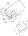
- FIG. 1 is a perspective view of a contents movement mechanism including a passage device according to a first embodiment of the present invention.
- FIG. 2 is an exploded perspective view of a contents moving mechanism having a passage device according to a first embodiment of the present invention.
- FIG 3 is a side cross-sectional view of a contents movement mechanism having a passage device according to a first embodiment of the present invention.
- FIG. 4 is a main part view showing the tilting state of the passage device according to the first embodiment of the present invention.
- FIG. 5 is a cross-sectional view showing a state in which the contents passage means maintains the initial state when the housing of the contents movement mechanism having the passage device according to the first embodiment of the present invention is tilted.
- FIG. 6 is a cross-sectional view showing a state in which the contents passing means according to the first embodiment of the present invention starts to move due to a pushing force of the contents.
- FIG. 7 is a cross-sectional view showing a state in which the contents passing means according to the first embodiment of the present invention is moved by the pushing force of the contents.
- FIG. 8 is a cross-sectional view showing a state in which the contents passing means according to the first embodiment of the present invention is moved by the pushing force of the contents.
- FIG. 9 is a view showing a state in which contents are passed through the contents passing means according to the first embodiment of the present invention.
- FIG. 10 is a cross-sectional view showing a state of use of a contents movement mechanism including a passage device according to the first embodiment of the present invention.
- FIG. 11 is a front sectional view of a contents movement mechanism including a passage device according to the first embodiment of the present invention.
- FIG. 12 is a bottom cross-sectional view of a contents movement mechanism including a passage device according to the first embodiment of the present invention.
- FIG. 13 is a sectional view showing a state of returning to an initial state after use of a contents moving mechanism having a passage device according to the first embodiment of the present invention.
- FIG. 14 is a cross-sectional view showing an example of the installation structure of the sensor unit according to the first embodiment of the present invention.
- FIG. 15 is a cross-sectional view of a contents transfer mechanism having a passage device according to a second embodiment of the present invention.
- 16 is a cross-sectional view of a contents conveyance mechanism having a passage device according to a third embodiment of the present invention.
- FIG. 17 is a cross-sectional view of a contents transfer mechanism having a passage device according to a fourth embodiment of the present invention.
- FIG. 18 is a block diagram of a passage device for sensing the movement of contents according to a fifth embodiment of the present invention.
- FIG. 19 is a flowchart illustrating the operation of the passage device according to the fifth embodiment of the present invention.
- FIG. 20 is a block diagram of a passage device for sensing the movement of contents according to a sixth embodiment of the present invention.
- FIG. 21 is a flowchart illustrating the operation of the passage device according to the sixth embodiment of the present invention.
- FIG. 22 is a block diagram of a passage device for sensing movement of contents according to a seventh embodiment of the present invention.
- FIG. 23 is a flowchart illustrating an operation process of the passage device according to the seventh embodiment of the present invention.
- FIG. 24 is a block diagram of a passage device for detecting the movement of contents according to an eighth embodiment of the present invention.
- FIG. 25 is a diagram showing a change in light amount of a relatively small, flat tablet when the container according to the eighth embodiment of the present invention is tilted to the outside through the sensor portion.
- FIG. 26 is a diagram showing a change in light amount of a relatively large and long pellet when the container according to the eighth embodiment of the present invention is tilted to the outside through the sensor portion.
- FIG. 27 is a view showing a change in light amount in a case where a relatively small and flat pellet is tilted in a container according to an eighth embodiment of the present invention, to be.
- FIG. 28 is a graph showing a change in light amount in the case where a relatively large and long pellet is tilted in a container according to an eighth embodiment of the present invention, to be.
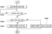
- FIG. 29 is a flowchart illustrating an operation procedure of a passage device according to an eighth embodiment of the present invention.
- FIG. 30 is a block diagram of the medication management device according to the ninth embodiment of the present invention.
- 31 is a block diagram of a medication guidance terminal of the medication management device according to the ninth embodiment of the present invention.
- FIG. 32 is a block diagram of a medication guidance terminal according to a ninth embodiment of the present invention.
- FIG. 32 is a block diagram of a medication guidance terminal according to a ninth embodiment of the present invention.
- FIG 33 is a flowchart illustrating an operation of the medication management device according to the ninth embodiment of the present invention.
- FIG. 34 is a perspective view of a housing having an medication management device according to a ninth embodiment of the present invention.
- 35 is a communication system of the medication management device according to the ninth embodiment of the present invention.
- FIG. 36 is a communication operation diagram of the medication management apparatus according to the ninth embodiment of the present invention.
- FIG. 37 is a block diagram of the medication management apparatus according to the tenth embodiment of the present invention.
- FIG. 38 is a block diagram of a dispenser according to a tenth embodiment of the present invention.
- 39 is a perspective view of a substrate according to a tenth embodiment of the present invention.
- FIG. 40 is a sectional view of a dispenser according to a tenth embodiment of the present invention.
- 41 to 43 are views showing a process of discharging the contents of the dispenser according to the tenth embodiment of the present invention.
- 44 is a block diagram of a management terminal according to a tenth embodiment of the present invention.
- 45 is an exploded perspective view of a dispenser connected to a management terminal according to an embodiment of the present invention.
- 46 is a perspective view of a plug cap of a dispenser connected to a management terminal according to an embodiment of the present invention.
- 47 is an exploded perspective view of a plug cap of a dispenser connected to a management terminal according to an embodiment of the present invention.
- One embodiment of the passage device comprises a passage operating part for guiding movement of contents; A passing motion part rotatably provided in the passage operating part and being moved so as to allow the contents to pass therethrough; And a sensing unit provided in the passage actuating unit for sensing the contents discharged by the free pivoting movement of the one end of the passage moving unit, and the sensing unit detects information of the sensed contents.
- the passage moving part may further include a blocking member for blocking the passage of the contents exceeding the set amount.
- the sensing unit may include at least one light emitting unit that emits light in the direction of contents discharged by the pivotal movement of the passage unit, at least one light receiving unit that receives light emitted from the light emitting unit, And a sensing controller for sensing the contents discharged through the passage actuating part using the light received by the light receiving part.
- the present invention may further comprise a storage unit for storing the contents information detected by the sensing unit, and may further include a measurement unit for calculating an accumulated discharge amount of the contents based on the information stored in the storage unit. And a display unit for outputting contents information detected by the sensing unit, information stored in the storage unit, or information calculated by the measuring unit.
- the present invention is characterized by further comprising a communication unit for transmitting contents information detected by the sensing unit, information stored in the storage unit, or information calculated by the measuring unit to an external device through wired or wireless communication .
- the sensing control unit of the present invention is characterized in that it is determined based on the information stored in the storage unit whether the cumulative discharge amount of the contents over the period exceeds or is insufficient for the period.
- the sensing control unit of the present invention is characterized in that when the reception of the light reflected by the content is interrupted, it is determined that the contents have been discharged by the passage operation unit.
- the sensing unit may further include a tilt sensor that senses a tilt of the passing device, wherein the sensing control unit controls the tilt of the container by the passage unit depending on whether the tilt of the container detected by the tilt sensor is within a predetermined set slope It is determined that the contents have been discharged.
- the sensing control unit determines that the contents are discharged if the electric wave reflected by the contents is not received by the receiving unit while the inclination of the housing detected by the tilt sensor is within a predetermined set inclination, When the inclination of the housing detected by the inclination sensor is out of a preset slope and the radio wave reflected on the contents is not received by the receiver, it is determined that the contents are not discharged.
- the light emitting portion and the light receiving portion of the present invention are installed on both sides of the passing motion portion.
- the sensing control unit of the present invention determines that the contents are discharged by the passage operation unit according to a change in the amount of light reflected by the contents after being emitted by the light emitting unit and received by the light receiving unit.
- the sensing control unit of the present invention is characterized in that if the amount of change in the amount of light received by the light receiving unit is equal to or larger than the set change amount, the passage control unit determines that the contents have passed.
- the present invention further includes a tilt sensor for sensing a tilt of the housing, wherein the sensing control unit controls the tilt of the housing by sensing whether the tilt of the housing detected by the tilt sensor is within a predetermined set slope, .
- the sensing control unit of the present invention determines that the contents are discharged when the amount of change in the amount of light is equal to or larger than the set change amount while the inclination of the housing detected by the tilt sensor is within a predetermined set inclination, When the detected inclination of the housing is out of the predetermined set inclination and the change amount of the light amount is equal to or larger than the predetermined set change amount, it is determined that the contents are not ejected.
- the sensing control unit of the present invention determines that the contents have been discharged by the passage operation unit when the amount of light received by the light receiving unit becomes equal to or greater than a predetermined set light amount and becomes a state less than the set light amount.
- the present invention further includes a tilt sensor for sensing a tilt of the housing, wherein the sensing control unit controls the tilt of the housing by sensing whether the tilt of the housing detected by the tilt sensor is within a predetermined set slope, .
- the sensing control unit determines that the contents are discharged when the light amount is less than the set light amount while the inclination of the housing detected by the inclination sensor is within a predetermined set inclination, It is determined that the contents have not been discharged when the light amount is less than the set light amount in a state where the inclination of the housing is out of a predetermined set inclination.
- An apparatus for managing medicines includes an output unit; And a control unit for receiving medication state information from the sensing unit and receiving medication schedule information from the medication management server, generating medication map information for the user using the medication schedule information and the medication state information, And a terminal control unit, and the output unit outputs the medication map information as an image or a voice.
- the passage portion of the passage device includes an opening member which is pivoted in the passage direction of the contents to form a passage space for the contents.
- the passage portion is rotatable in a direction in which the contents are passed by the self weight of the contents to be contacted, and can allow a predetermined amount of the contents to pass through.
- the passage operating portion includes a fixing member that forms an opening to allow passage of the contents, and a movement guide portion that extends from the fixing member so that the contents are guided into the contents passage means side.
- the movement guiding part is extended from the movement guiding part so as to be in contact with or in proximity to the inner side surface of the adjacent housing and guides the contents to the opening part side And an induction portion.
- the content guiding portion may be formed along the inner circumferential surface of the housing.
- the movement guide portion includes a cover portion formed along the inner circumferential surface of the housing and extending from the fixing member so that contents stored in the housing are guided to move toward the opening portion.
- the passing device includes a housing for storing contents and a passage operating part provided inside the housing for guiding movement of the contents.
- a content guiding part formed in the housing for setting a moving direction and a moving state of the content so that the content stored in the housing is guided to the passing operation part side by one or a predetermined amount when the housing is tilted.
- the passage operating portion includes a contents passage means for allowing the contents to move, and the contents passage means includes a passage movement portion for allowing the contents to pass through by opening by movement.
- the passage portion includes an opening member which is moved in the passage direction of the contents to form a passage space for the contents; And a blocking member interlocking with the opening member and blocking at least a part of the opening so that the contents do not pass through or only partially pass through the blocking member, wherein the blocking member is interlocked with the opening member, Can be prevented from passing through the opening portion.
- the passage operating portion includes: a fixing member for forming the opening portion for passing the contents therethrough; And a movement guide portion for allowing the contents to be introduced and guided toward the contents passing means side, wherein the housing mounts the fixing member, and the contents can be guided to move toward the movement guide portion through the contents guide portion.
- the housing includes: a shaft-shaped portion that receives the fixing member and is configured to move and guide the contents to the movement guide portion; And an enlarged diameter portion that is larger in internal space than the reduced diameter portion so that the contents can be initially stored by a preset amount.
- the fixing member may detachably connect the movement guide portion.
- the content guiding portion may be convex and curved inward along the circumferential trajectory in the housing.
- the content guide portion may be formed on the enlarged diameter portion or the reduced diameter portion to guide the movement of the contents.
- the passage operating portion forms a supply guide entrance portion so that the opening portion guides the passage of the contents, and the opening portion is formed to be opened toward the contents guide portion side, and the contents stored in the housing are guided along the contents guide portion And can be moved toward the opening portion through the supply guide entrance portion.
- the passage operating portion includes a contents passage means for allowing the contents to move
- the contents passage means includes a passage portion for allowing the contents to pass through opening by pivoting movement
- the opening portion can be opened and closed while being reciprocated by using the lever principle in the opening portion.
- the passage movement part includes a motion control member for setting the center-of-gravity balance of the leverage movement.
- the housing may form a passage mechanism neck to guide the contents, which are moved along the contents guide section, toward the passage operating section side by a predetermined amount.
- the passage portion includes an opening member which is moved in the passage direction of the contents to form a passage space for the contents, and the passage mechanism neck portion may be formed in the housing to guide the contents to the opening member side.
- the housing or the passing operation portion may be formed with a passing mechanism extension portion for securing a space so that the contents passing means is rotated while adjusting the weight balance and the passage of the contents can be guided.
- the passage operating portion comprises: a fixing member having an opening portion for allowing passage of contents and having a contents passage means for permitting movement of a predetermined amount of contents; And an inner cap detachably coupled to the fixing member and detachably coupled to the content discharge side of the housing and allowing the discharge of the contents, wherein when the inner cap separates from the housing, And can be detached from the housing while being coupled to the inner cap.
- the inner cap may be formed in a ring shape, and the fixing member may form a rim to be detachably coupled to the inner surface of the inner cap.
- the inner cap or the housing may include an outer cap detachably.
- the inner cap or the housing may hinge the outer cap.
- the passing device comprises: a passage operating part for guiding the movement of the contents with the opening part, the passage operating part comprising contents passage means for allowing the contents to move,
- the passage operating portion may form a supply guide entrance portion so that the contents can enter the opening portion from the circumferential surface of the passage operating portion along the inner surface of the housing.
- the passage portion is provided so as to be capable of seesawing in the opening portion and the passage operation portion can keep the initial state and not open the opening portion when the passage operation portion is inclined within the set angle by the seesaw motion have.
- the setting angle may be set to a tilt angle that does not exceed 180 degrees from the initial state in which the contents movement mechanism with the opening formed is erected.
- the passage moving part includes an opening member which is moved in the passage direction of the contents to form a passage space for the contents, and when the contents movement mechanism with the opening part is inclined within a set angle, So that the opening member can keep the state of blocking the opening portion.
- the passage portion can perform a seesaw motion by gravity biasing phenomenon on the left side or the right side with respect to the movement member as the rotation center.
- passage movement part is weighted on the blocking member side with respect to the movement member as the rotation center in a wait state in which the contents movement mechanism having the opening part is inclined and the blocking member is hooked on the stopper, It is possible to maintain the state of opening without blocking the opening.
- the contents can be guided to pass through the predetermined amount by opening the opening by the force of pushing the contents of the contents through the passage portion or by the force of the contents pushing the passage portion and the weight of the passage portion.
- the passage movement portion is rotated based on the movement member, which is the center of rotation, and the opening portion is opened, the weight of the contents flowing into the opening portion side is weighted.
- the passage portion includes a blocking member which interlocks with the opening member and blocks at least a part of the opening portion so that the contents do not pass through or pass only partially.
- the passage section may be maintained in an initial state by the stopper when the passage operating section does not contact the contents within a preset angle.
- the passage portion may be moved with the contents by friction with the contents contacting the bottom member between the opening member and the blocking member or by a pushing force of the opening member by the contents.
- the passing device comprises: a passage operating part for guiding the movement of contents having an opening part, the passage operating part including contents passage means for allowing the contents to move, And the passage portion is reciprocated in the opening portion by using the lever principle on the basis of the movement member to open and close the opening portion.
- the passage movement portion maintains the state in which the opening portion is closed by its own weight when the passage operation portion rotates within a set angle, and the passage movement portion is closed by the pushing force of the contents or the force pushing the contents through the passage movement portion, And the contents can be guided through the predetermined amount of the contents.
- the passage section includes an equilibrium section for preventing inclination of the passage operating section beyond the inclination of the passage operating section due to the self weight of the passage moving section when the passage operating section is inclined.
- the passage portion includes an opening member which is moved in the passage direction of the contents to form a passage space for the contents.
- the passage portion includes a blocking member which interlocks with the opening member and blocks at least a part of the opening portion so that the contents do not pass through or pass only partially.
- the shape of the passage actuating part may be provided so that the rotation of the passage moving part due to its own weight does not occur due to the weight balance until the content of the set amount is contacted with the opening member.
- the passing motion portion further includes a motion control member for setting the center-of-gravity balance of the leverage motion.
- a valve according to the present invention is a passage device for guiding passage of contents, comprising a passage actuating part for passing contents therethrough, the passage actuating part including contents passage means for moving the contents.
- the contents movement mechanism comprises: a passage device provided in a contents movement mechanism for containing contents and guiding the contents through; And a housing which is open at least to one side, the passage device comprising a passage actuating part for passing contents therethrough, the passage actuating part including contents passage means for allowing the contents to move.
- a contents movement mechanism comprises: a housing for storing contents; And a passage operating portion for guiding the movement of the contents of the housing.
- the passage operating portion includes a contents passage means for allowing the contents to move.
- the content passing means includes a passing motion portion for allowing the contents to pass through by opening by motion.
- the passage portion includes an opening member which is moved in the passage direction of the contents to form a passage space for the contents.
- the passage portion is rotatable in a direction in which the contents are passed by the self weight of the contents to be contacted, and can allow a predetermined amount of the contents to pass through.
- the passage operating portion includes: a fixing member detachably provided in the housing to form an opening portion for passing the contents therethrough; And a movement guide portion for allowing the contents of the housing to be introduced and guided to the contents passage means side.
- the movement guiding portion includes a content guiding portion which extends in contact with or close to the inner side surface of the adjacent housing to guide the contents to the opening portion side.
- the content guiding portion may be formed along the inner circumferential surface of the housing.
- the passage actuating part is detachably provided in the housing, and the movement guiding part can be formed in the housing.
- the accommodating mechanism comprises: a passing device provided in a receiving mechanism for holding contents and guiding the contents through; And a housing which is open at least to one side, the passage device comprising a passage actuating part for passing contents therethrough, the passage actuating part including contents passage means for allowing the contents to move.
- a contents mechanism comprises: a passage device including contents and guiding the contents through; And a housing which is open at least to one side, the passage device comprising a passage actuating part for passing the contents, the passage actuating part including contents passage means for allowing the contents to move.
- FIG. 1 is a perspective view of a contents movement mechanism including a passage device according to a first embodiment of the present invention
- FIG. 2 is an exploded perspective view of a contents movement mechanism including a passage device according to the first embodiment of the present invention.
- FIG. 3 is a side sectional view of a contents moving mechanism having a passage device according to the first embodiment of the present invention
- FIG. 4 is a main part view showing the tilting state of the passage device according to the first embodiment of the present invention
- Figure 6 is a cross-sectional view of the contents conveying means according to the first embodiment of the present invention.
- Figure 6 is a cross-sectional view of the contents conveying device according to the first embodiment of the present invention
- the passage means is a sectional view showing a state in which movement is started by the pushing force of the contents.
- FIG. 7 is a cross-sectional view showing a state in which the contents passing means according to the first embodiment of the present invention is moved by the pushing force of the contents
- FIG. 8 is a cross-sectional view of the contents passing means according to the first embodiment of the present invention
- FIG. 9 is a view showing a state in which the contents passing means according to the first embodiment of the present invention is discharged.
- FIG. 10 is a cross- 11 is a front cross-sectional view of a contents movement mechanism including a passage device according to the first embodiment of the present invention
- Fig. 12 is a sectional view of the contents movement mechanism with the passage device according to the first embodiment of the present invention Fig.
- FIG. 13 is a view showing a state of returning to the initial state after use of the contents movement mechanism including the passage device according to the first embodiment of the present invention.
- FIG. 14 is a cross-sectional view showing an example of the installation structure of the sensor unit according to the first embodiment of the present invention.
- a contents movement mechanism 1 including a passage device 100 includes a housing 110, a passage operation part 120, (119).
- the housing 110 is a container for storing the contents 5.
- the housing 110 has a passage operation part 120 inside and forms a passage mechanism entrance part 119.
- the contents 5 are allowed to pass through the contents passing means 123, such as solids, powder or liquid.
- the housing 110 forms the pre-passage portion 113, which is a portion for storing the contents 5 before the passage operation portion 120.
- the housing 110 can form the atmospheric storage part 115 in the space after the contents 5 pass through the pass-through part 120.
- the pre-passage portion 113 is a space inside the housing 110 for storing contents
- the atmospheric storage portion 115 means a space or an open side for waiting for the contents 5 to be drawn out.
- the pre-passage portion 113 and the atmospheric storage portion 115 communicate with each other through the open portion 122 formed in the passage operating portion 120 and the contents 5 can be moved to the atmospheric storage unit 115.
- the passage operating part 120 is provided inside the housing 110 and serves to guide the movement of the contents 5.
- the passage operation part 120 serves to guide the movement of the contents 5 by a quantitative amount or a demand amount (demand amount).
- quantity refers to the quantity or quantity that is moved differently within the same number, quantity, error, and allowable range.
- Quantity is the amount (number) required by the user and is included in the category of “quantity” .
- the passage operating portion 120 includes the contents passage means 123 and the passage passage portion 139.
- the contents passing means 123 serves to allow the contents 5 to pass from the pre-passage portion 113 side to the atmosphere storage portion 115 side.
- the contents passage means 123 includes the passage movement part 140.
- the passage moving part 140 serves to allow the contents 5 to pass through by opening by the motion.
- the pass motion part 140 serves to close the open part 122 which is opened by being interlocked with the opening member 124.
- the passage portion 140 includes the blocking member 127 and the opening member 124.
- one contents is quantitative
- another piece of contents 5 is adjacent to the rear portion of the contents 5
- Passes through the passage portion 139 and the rear pass contents 5 moves and contacts the blocking member 127.
- the blocking member 127 is formed by bending, and the blocking member bending portion 127b of the blocking member 127 may be linearly curved or curved.
- the angle of the blocking member bending portion 127b at which the blocking member 127 is bent may be configured to be a steep slope close to a right angle so that the contents other than the demanded amount do not enter the passage operating portion 120. [ Of course, it is possible to bend at various angles.
- the blocking member 127 prevents the contents 5 from flowing into the opening 122 in excess of the predetermined amount as blocking the opening 122 at least partly.
- the opening member 124 closes the opening 122 so that external substances such as air and dust can be introduced into the housing 110 through the opening 122 in a state where the housing 110, Entry is suppressed.
- the passage movement part 140 in the initial state in which the housing 110 is raised (0 degree rotation state), the passage movement part 140 has a weighting action to the right which is to be rotated in the clockwise direction by the action of the force to move in the weight balance state It is restrained by the stopper 129 to maintain the weight balance state (stopped state). Particularly, when the pass motion part 140 is in the right side weight position, the stopper 129 at the upper left side suppresses the clockwise rotation of the pass motion part 140.
- stopper 129 can be changed into various shapes and positions.
- a separate tilt sensor 530 is mounted to reduce the amount of power generated when the sensor unit 510 is continuously operated and when the tilt sensor 530 is operated, It is possible to switch.
- the sensor unit 510 and the tilt sensor 530 will be described later.
- Fig. 4 shows the state of the passage movement part 140 as the housing 110 is inclined to guide the passage of the contents 5.
- the passage movement part 140 is bi-directionally rotated (moved) with the movement member 125 as the reference C.
- FIG 5 shows the state of the passage part 140 when the housing 110 is tilted 135 degrees counterclockwise in the initial state.
- the housing 110 when the housing 110 is inclined by 135 degrees in the counterclockwise direction, the housing 110 inclines to the left (relative to the motion member 125), which is the direction in which the passage portion 140 is positioned, 90 degrees), so that the contents 5 do not slip.
- the inclination angle of the housing 110 is not limited.
- the downward direction of the vertical line of the rotary shaft 125 of the passage unit 140 indicates the gravity direction.
- the right side weight is larger, so that a force is generated to cause the passage portion 140 to rotate in the right direction, but no substantial rotation is caused by the stopper 129.
- the housing 110 when the housing 110 is in a horizontal state (-90 degrees), the right side of the vertical line C is heavier and a force is generated to cause the passage portion 140 to rotate clockwise in the clockwise direction, Rotation does not occur. Accordingly, the housing 110 moves along the wrist axis 140 without rotating itself.
- the passage movement part 140 moves in response to the movement of the contents due to the gravity action and opens the passage operation part 120 so that the contents pass therethrough.
- the passage movement part 140 is formed such that the passage operation part 120 is inclined.
- the rotational movement of the passage unit 140 for passing the contents is performed such that the position of the rotational center 210 of the motion unit, which is the rotational center of motion of the passage unit 140, is located in the downward direction, Gravity movement of the contents or transmission of the motion of the contents to the passage movement part 140 by an operation in which the passage operation part 120 is tilted, inverted or shaken.
- the rotational motion of the passage moving part 140 can be made by the movement force of the contents passing means 123 as the self-weight of the contents is pressed.
- the position of the center of gravity 215 of the moving part of the passage part 140 is located in the direction opposite to the direction of passage of the passage device 100 that is behind the position of the moving part rotation center 210 of the passage part 140,
- the rotational movement of the passage portion 140 may be inhibited or delayed due to the difference in the position of the rotation center 210.
- the passage portion 139 serves to limit the amount of movement of the contents 5 moving to the contents passing means 123.
- the passage passage portion 139 has a passage width minimum inner diameter L1 of the inner space of the passage passage portion 139, which is the minimum inner diameter of the passage passage portion 139, when the length of the one end portion of the passage 5 is different from that of the other end portion (5) is smaller than or equal to twice the content unidirectional maximum outer diameter (L2) of the maximum unidirectional length of one unidirection, so that two or more individual contents (5) can not enter or pass through the passage portion (139) at the same time, Only one single contents 5 can be entered or passed through the passage portion 139 at a time.
- the passage passage portion 139 passes through the passage portion 139 in the longitudinal direction end length direction L3 when the length of the one end portion of the contents 5 passing through is different from the length of the other end portion .
- the contents passage means 123 includes a blocking member 127 which closes the open portion 122 which is opened by being interlocked with the opening member 124 and one piece of contents 5 passes through the passage portion 139 in the forward direction
- the other individual contents 5 are rearwardly passed through the passage portion 139 adjacent to the rear of the front passing contents 5 and the rear pass contents 5 move and contact the blocking members 127, (127) prevents at least a portion of the openings (122) from exceeding a predetermined amount as the contents are prevented from entering the openings (122).
- the opening member 124 before the content of the contents 5 reaches a position where the opening member 124 is located, the contents of the contents of the contents of the opening of the passage member 140 5, the opening member 124 is in a closed state, the blocking member 127 is in an open state, and a predetermined amount of the contents is stored in the passage operating portion 120 The same standby state is maintained.
- the opening member 124 and the blocking member 127 cooperate to rotate and the opening member 124 is opened when the contents 5 of a fixed amount contact the opening member 124, State, and the blocking member 127 is in a closed state. At this time, according to the closed state of the blocking member 127, the contents other than the fixed amount are prevented from entering the opening portion 122 continuously.
- the passage moving part 140 is rotatably provided on the fixing member 121 corresponding to the inner side surface of the opening part 122 so that the passage operating part 120 is rotated in the order of connection from FIG.
- the passage movement part 140 returns to the state in which the blocking member 127 is opened with respect to the movement member 125 as shown in FIG. 3 or 12 by the weight balance force of the passage movement part 140.
- a movement guide portion 180 for introducing the contents 5 into the passage portion 139 is provided at a lower portion of the passage portion 139.
- the movement guide portion 180 is formed to be inclined so that the contents 5 are guided along the inclined surface to the position where the passage portion 139 is located.
- the passage operating portion 120 is formed such that the opening portion 122 rises to a certain height while having the opening portion 122.
- the movement angle of the opening member 124 is controlled by at least one of the stopper 129 provided in the contents passing means 123 and the cover 30 connected to the housing 110 having the passage operation portion 120 Lt; / RTI >
- the stopper 129 extends from the motion member 125 so that the opening member 124 is not moved anymore, and the blocking member 127 maintains a state of completely blocking the opening 122.
- the stopper 129 is formed in the contents passing means 123 or the housing 110 to limit the rotation angle of the opening member 124.
- the contents receiving mechanism 1 having the passing device 100 may be a container mechanism.
- the contents passage means 123 includes a passage portion 140 for allowing the contents 5 to pass through by opening by movement.
- the passage portion 140 is provided with an opening member 124 which is moved in the passing direction of the contents 5 to form a passage space of the contents 5 and an opening member 124 interlocked with the opening member 124, And a blocking member 127 for blocking at least a part of the opening 122 so as not to pass through the opening 122 or to pass only partly.
- the passage operating portion 120 includes a fixing member 121 for forming an opening portion 122 for passing the contents and a movement guide portion 122 for guiding the contents 5 to flow into the contents passing means 123 side 180).
- the contents (5) are passed by the deformation of the contents passing means (123), in particular, by the rotation of the opening member (124).
- the passage operating portion 120 forms an opening portion 122 communicating with the pre-passage portion 113 located before the contents 5 pass, so that the contents 5 located at the pre-passage portion 113 To be passed.
- the contents passing means 123 moves the contents 5 through the opening 122.
- the passage space of the contents 5 is such that the unfixed free end of the opening member 124 is pressed by the weight of the contents 5, the swing of the housing 110 with the passage operation part 120, May be formed as it is moved by at least one of its own weight.
- the passing device 100 can be applied to the contents moving mechanism 1 or the receiving mechanism and can be an opening / closing mechanism that can be opened and closed from the body of the contents moving mechanism 1 or the receiving mechanism.
- the passing device 100 includes the passing operation part 120.
- the passage operating portion 120 guides the contents 5 of the pre-passage portion 113 of the contents movement mechanism 1 or the body of the accommodation mechanism to the passage device 100 side.
- the main body of the contents moving mechanism 1 or the receiving mechanism may be referred to as the housing 110.
- the passage portion 140 includes a motion member 125.
- the motion member 125 may movably connect the opening member 124.
- the passage operating portion 120 includes a passage portion 139 formed so as to extend from the passage discharge side which is the side where the contents 5 contact the contents passing means 123 to the passage entry side which is the side where the contents 5 enter .
- the passage portion 139 serves to guide the contents 5 to the contents passing means 123.
- the passage portion 140 also prevents the passage portion 140 from tilting with the passage portion 120 at a slope exceeding the slope of the passage portion 120 when the passage portion 120 is inclined And an equilibrium portion 123b.
- the opening member 124 may be connected to the fixing member 121 directly or indirectly.
- the passage portion 140 moves in a direction opposite to the direction in which the passage portion 120 is inclined
- the weight 124 of the opening member 124 tilts more than an angle at which the passage operating portion 120 is tilted in the direction in which the passage operating portion 120 is tilted by the weight of the opening member 124 .
- the balance portion 123b is configured such that a force is generated that rotates in a direction opposite to the tilting direction of the passage operating portion 120 tilted to allow the balance state of the balance portion 123b to pass through the contents 5,
- the weight balance of the portion 123b acts to force the opening member 124 to rotate in the direction opposite to the tilting direction of the passage operating portion 120 without being tilted in the tilting direction of the passage operating portion 120.
- the fixing member 121 may be provided on the inner peripheral surface of the through-hole of the passage device 100 to which the opening member 124 is connected, or may be a member of the housing 110 included in the passage device 100.
- the effective passage space of the opening portion 122 becomes narrow due to movement of the contents in the outer circumferential direction of the movement fixing portion 125a, thereby preventing passage of the contents other than the demanded amount.
- the equilibrium portion 123b is inclined in the tilting direction of the ball portion 123b and the weight of the ball portion 123b generated by the weight of the content 5 added to the ball portion 123b side of the ball portion 123b If the weighting in the tilting direction exceeds the balance holding force for reaching the equilibrium position of only the equilibrium portion 123b to be rotated in the direction opposite to the inclination of the passage operating portion 120, the equilibrium portion 123b Is rotated in the tilting direction of the passage operating portion 120. As shown in Fig.
- the shape of the passage portion 140 may be formed such that the passage portion 140 does not rotate due to the self weight of the passage portion 140 prior to the contact of the passage portion 140 with the structural member of the passage portion 140.
- the contents passing means 123 includes a motion member 125, which rotatably couples the opening member 124.
- the passage operating portion 120 includes a fixing member 121 having an opening portion 122 for passing the contents 5 therein.
- the contents passing means 123 includes an opening member 124 and a motion member 125.
- the opening member 124 is connected to the fixing member 121. Thus, the opening member 124 is moved and can receive and guide the contents 5 depending on whether the opening portion 122 is open or not.
- the motion member 125 movably connects the opening member 124.
- the passage movement part 140 is provided with a slope of the contents movement mechanism or the accommodation mechanism 1 so as to maintain or balance the center of gravity of the passage movement part 140 when the contents movement mechanism or the accommodation mechanism 1 is inclined
- the passage portion 140 becomes an equilibrium portion 123b that does not slant more than the inclination of the contents movement mechanism or the accommodation mechanism 1.
- the direction of the force of rotation to rotate or equilibrate the passage portion 140 or the equilibrium portion 123b is determined by the direction of movement of the passage movement portion 140 (i.e., in the direction opposite to the inclination of the contents movement mechanism or the accommodation mechanism 1) Or the equilibrium portion 123b is generated by a force for rotating.
- the passage unit 140 may include a separate motion control member 123a for the center of gravity of the passage unit 140.
- the motion control member 123a is configured to move the weight of the opening member 124 and the motion control member 123a or the weight of the opening member 124, the motion control member 123a, By the weight of the separate member moving together with the weight 124, the force of the weight balance acting on the center of gravity of the balance portion 123b and the force of maintaining the center of gravity position in the direction of gravity causes the opening member 124 It can be prevented from tilting at a slope exceeding the slope of the passage operating portion 120.
- the passage movement portion 140 is moved in the direction opposite to the direction in which the passage operation portion 120 is tilted,
- the opening member 124 is prevented from tilting by more than an angle at which the passage operating portion 120 is tilted in the direction in which the passage operating portion 120 is tilted by the weight of the opening member 124.
- the balance portion 123b including the opening member 124 slips down as the through operation portion 120 is tilted and comes into contact with the opening member 124 so that the weight of the contents contacts the opening operation portion 120
- the opening member 124 is moved in the direction in which the opening member 124 is opened for discharging the contents before movement of the opening member 124 due to its own weight And is kept in the open standby state until the contents are brought into contact with each other.
- the passing motion part 140 becomes the equilibrium part 123b, and the equilibrium part 123b is formed in the direction opposite to the tilting direction of the passing operation part 120 in which the balance equilibrium state of the equilibrium part 123b is inclined to pass the contents A force to rotate can be generated.
- the balance member 123b acts on the opening member 124 not to be tilted in the tilting direction of the passage operating portion 120 but to rotate in the direction opposite to the tilting direction of the passage operating portion 120.
- the force by which the balance portion 123b is rotated in the opposite tilt direction of the passage operating portion 120 is resisted by the member of the contents mechanism such as the fixing member 121 or the housing 110, The rotation can be suppressed so as not to occur.
- the balance portion 123b is not tilted in the tilting direction of the passage operating portion 120 due to the force for holding or rotating in the equilibrium state of the balance portion 123b and the force of the holding member 121 or the housing 110,
- the rotation of the passage operating portion 120 in the counterclockwise direction due to the force for holding or rotating the balancing portion 123b in the equilibrium state is suppressed.
- the weight portion of the ball portion 123b is inclined in the tilting direction of the ball portion 120 and the ball portion 123b is tilted in the tilting direction of the ball portion 120 caused by the weight of the content added to the opening portion 124 side of the ball portion 123b If the weighting of the balance portion 123b exceeds the balance holding force for reaching the balanced position of only the balance portion 123b rotating in the direction opposite to the inclination of the passage operating portion 120, And is rotated in the tilting direction of the passage operating portion 120.
- the rotation of the balance portion 123b is contact-resisted with the member of the contents mechanism such as the fixing member 121 or the housing 110, and the balance portion 123b rotates more than necessary in the inclination direction of the passage operation portion 120 Can be suppressed.
- the balance part 123b or the passage part 140 is weighted by the center of gravity of the balance part 123b or the passage part 140
- the equilibrium portion 123b or the passage portion 140 is not tilted beyond the inclination of the passage portion 120 by the action of the force for balancing to maintain the position and inclination in the passage portion 120 .
- the pass motion part 140 is provided so as to be seesaw in the opening part 122, so that when the pass operation part 120 is inclined within the set angle by seesaw motion, So that the opening member 124 does not open the opening 122.
- the contents of the contents are passed through the predetermined amount by opening the opening portion 122 by the force of pushing the contents of the contents through the passage portion 140 or the force of the contents pushing the passage portion 140 and the weight of the passage portion 140.
- the setting angle can be set to a tilt angle that does not exceed 180 degrees from the initial state in which the contents moving mechanism or receiving mechanism 1 forming the opening 122 is erected.
- the passage moving part 140 can perform a seesaw motion by a weight biasing phenomenon on the left or right side with respect to the moving member 125 which is the rotation center.
- the passage moving part 140 is provided on the blocking member 127 side with respect to the moving member 125 which is the rotation center in the standby state in which the contents moving mechanism or the accommodation mechanism 1 in which the opening part 122 is formed is inclined
- the blocking member 127 is caught by the stopper so that the blocking member 127 can maintain a state in which it opens without blocking the opening portion 122.
- the passage movement portion 140 causes the opening member 124 to move in the direction of the opening (122).
- the passage movement part 140 increases the weight of the contents introduced into the opening part 122 side, And the opening 122 can be opened.
- the passage portion 140 can open and close the opening portion 122 while being reciprocally rotated by the weight balance principle of the seesaw lever at the opening portion 122 with reference to the motion member 125.
- the passage movement part 140 maintains the state in which the opening part 122 is closed by its own weight when the passage operation part 120 rotates within a set angle and the force of pushing or pushing the contents through the passage part 140
- the opening portion 122 can be sequentially opened and closed by the own weight of the passage moving portion 140, and the contents can be guided through the set amount.
- the pass motion part 140 includes an equilibrium part 123b for preventing the pass-through part 120 from tilting beyond the tilt of the pass-through part 120 due to its own weight when the pass-through part 120 is inclined can do.
- the passage portion 140 may include an opening member 124 that is moved in the direction of passage of the contents to form a passage space for the contents.
- the pass motion portion 140 may include a blocking member 127 that interlocks with the opening member 124 to block at least a portion of the opening 122 such that the contents do not pass therethrough or only partially pass therethrough.
- the shape of the passage operating portion 120 or the contents passing means 123 is set such that the weight does not rotate due to the weight of the passage portion 140 until the content of the set amount reaches the opening member 124 .
- the passage movement part 140 may further include a motion control member 123a for setting the center-of-gravity balance of the leverage movement.
- the resistance member 110a limits the passage of the contents passing through the passage operating portion 120.
- the resistance member 110a limits the passage of the contents passing through the passage operation part 120 and the resistance member 110a restricts the passage of the contents through the blocking member 110a 127) to resist passage of the contents.
- the resistance member 110a may be configured to protrude into the pass-through operation part 120 so that the contents exceeding the demand amount can not easily enter. In addition, it is possible to more effectively block the entry of contents exceeding the demand amount in conjunction with the blocking member 127 which is moving.
- the resistance member 110a may be formed in various ways. For convenience, a part of the resistance member 182 is recessed inwardly.
- the passage moving part 140 includes a receiving member 127a.
- the receiving member 127a is moved in the direction of the opening member 124 in conjunction with the opening member 124 and receives the content of the required amount together with the opening member 124 and moves.
- the contents 5 are in contact with at least one of the resistance upper plate member 182 and the resistance side plate member 183, and limit the residual amount of the contents passed through the opening portion 122.
- the resistance upper plate member 182 may be provided in the movement guide unit 180 and the resistance side plate member 183 may be connected to the resistance upper plate member 182 or the fixing member 121.
- the resistance side plate member 183 can be formed on the surface of the fixing member 121 facing the passing direction of the contents 5, when the cover 30 to be opened is provided, So that the cover 30 is formed so as not to interfere with the movement of the contents.
- the resistance upper plate member 182 and the resistance side plate member 183 can be deformed into various shapes in the passing direction of the contents 5 and the passing side direction.
- the movement guide portion 180 forms the contents guide portion 188 on the inflow side of the contents 5.
- the content inducing portion 188 divides the height difference generated during the movement of the contents into the contents passing means 123 into a plurality of or more stages or a slope so that the difference in height does not prevent the movement of the contents, Thereby guiding the contents of the portion 113 to be stably moved to the passage portion 139.
- the contents inducing portion 188 can be deformed into various shapes.
- the passage device 100 further includes a passage mechanism entrance 119.
- the passage mechanism entrance portion 119 is formed in the housing 110 to set the movement direction and the movement state of the contents 5 so that the contents 5 to be moved to the discharge side of the passage operation portion 120 are guided one by one or a fixed amount do.
- the housing 110 includes a reduced diameter portion 116 and a reduced diameter portion 117.
- the reduced diameter portion 116 is diametrically formed so as to receive the fixing member 121 and move the content 5 toward the movement guide portion 180 side.
- the diameter of the reduced diameter portion 116 may be similar to or the same as the circumferential trajectory formed along the contents guide portion 118, the guide member 190, and the resistance upper plate member 182.
- the enlarged diameter portion 117 is formed so as to have a larger inner space than the reduced diameter portion 117 so that the contents can be initially stored by the preset amount.
- the diameter of the enlarged diameter portion 117 is not limited.
- the passage mechanism entrance portion 119 is formed at a connection portion between the reduced diameter portion 116 and the enlarged diameter portion 117 of the housing 110 and formed convexly curved inward along the circumferential path.
- the contents 5 are moved along the passage mechanism entrance portion 119 and introduced into the inside of the contents guide portion 188 and the guide member 190 by a set amount.
- passage mechanism entrance 119 can be deformed into various shapes.
- the starting end of the content guiding portion 188 for guiding the contents to the passage portion 139 is in proximity to or in contact with the inner diameter of the reduced diameter portion 116 which is the neck portion of the housing 110 which is the container body of the present embodiment, do. Accordingly, the sliding start end of the content guiding portion 188 is positioned so as to be connected to the passing mechanism entering member 119 having a curved shape so that the movement of the contents is smoothly connected and the contents slip, 139).
- the injection blow container has a neck portion 116 that is narrower than the neck portion 117, which is the container body, for the reason that air pressure is applied to the opening of the container housing 110.
- the end portion of the contents guide portion 188 provided in the passage device 100 is inclined or bent or has an end, and the inside diameter of the container neck (small diameter portion)
- the inner diameter of the housing 117 may be entirely or partly connected to tilt the housing 110 to allow the contents to smoothly move to the passage portion 139 when the contents slip.
- the shape that connects the step between the content entering portion of the content guiding portion 188 and the thickened portion 117 A change unit 119 may be provided.
- the shape changing portion 119 is a passing mechanism entrance portion that connects the stepped portion of the reduced diameter portion 116 and the enlarged diameter portion 117 to guide the supply movement of the contents at the step within the housing.
- the content introduction portion which is the direction of the container bottom of the contents guide portion 188, may be inclined or curled or may be curled or curled in order to connect the stepped portion.
- the operating position of the opening member 124 is located inside the inner diameter of the container, and therefore, there is a step difference with the position of the contents approaching from the container body 117, And a content inducing part 188 which is formed of a curved, curved or single stage.
- the container body (housing 110) of the present embodiment is formed as a portion of the reduced diameter portion 116 that is narrower than the enlarged diameter portion 117 because the air pressure is applied to the upper opening of the body as the injection blow cylinder.
- the content guide portion 188 is provided to connect the stepped portion of the inner diameter of the reduced diameter portion 116 with the opening member 124 located at the inner diameter of the reduced diameter portion 116.
- the step connecting portion 188 connects the inside of the container shaft portion 116 and the inside of the container body 117, so that the slippage of the contents is smoothly connected.
- the penetration mechanism entrance portion 119 may serve to connect the step generated when the housing 110 is inclined to move the contents of the enlarged diameter portion 117 to the contents guide portion 188.
- the content guide 188 In order to insert the passage device 100 into the housing 110 when the step start point, which is the step start end in the direction of the bottom of the container guide 188, is larger than the inner diameter of the neck portion 116, the content guide 188 The lower part of the passage device 100 including the starting point of the container bottom direction of the contents inducing part 188 at the start of the step is inserted first in the vertical direction and then the position of the passage device is moved in the horizontal direction, So that three steps are required: vertical movement after assembly, horizontal movement after intermediate movement, and vertical movement.
- the start point of the contents guide portion 188 in which the content guide portion 188 of the passage device 100 is close to the inner diameter of the housing, and the guide member 190 are positioned inside the reduced diameter portion 116,
- the housing 100 When the housing 100 is assembled to the housing 110, it can be directly inserted in one direction.
- the housing 110 is composed of a convex body as an injection blow cylinder and a reduced diameter portion 116 in which a main portion of the passing device 100 is located.
- the passing device 100 is inserted into the housing 110, which is the container body, in one direction in one direction without movement.
- the upper end of the reduced diameter portion 116 may be configured to be wide or the stepped portion may be formed inside the reduced diameter portion 116 so as to support the passage device 100 from the upper portion to the lower portion when assembled with the container body.
- a groove may be formed on the upper end of the neck portion 116 to be held when inserted.
- Various shapes of stoppers may be coupled to the top of the reduced diameter portion 116.
- the housing 110 may be connected in a straight line without distinguishing between the enlarged diameter portion 117 and the reduced diameter portion 116, or may be formed in various shapes. That is, the housing 110 can be manufactured in various sizes such as containers having the same diameter.
- the opening member 124 keeps the state in which the opening portion 122 is closed by the force of the weight balance of the passage portion 140 in the initial standing state. That is, when a force to rotate to one side (right side) is applied, the stopper 129 prevents one rotation of the passage portion 140.
- the contents 5 are not slipped due to inclination toward the other side (left side) in the direction in which the passage portion 140 is located or not exceeding the horizontal.
- gravity acts in a direction perpendicular to the vertical center of the rotation center of the passage portion 140. Therefore, even if a force for rotating in one direction occurs due to a larger weight on one side in the vertical line reference, no substantial rotation is caused by the stopper 129.
- the blocking member 127 is in an open state and is in a standby state without movement of the passage moving part 140. At this time, the contents (5) slide in the gravity direction according to the inclination inside the housing (110).
- the tablet-like individual contents 5 can not be raised but can be introduced into the guide member 190.
- the rectangular shaped contents 5, which are not flat, are not raised but slid along the inclination of the guide member 190 stably.
- the contents 5 are discharged to the outside and are not in contact with the passage portion 140 so that the passage portion 140 is larger in weight on the right side and generates a force to rotate to the right but the remaining contents 5 are blocked by the blocking member 127 ) By gravity to maintain the state.
- FIG. 5 shows a state in which the housing 110 is tilted in the horizontal direction or more (-90 degrees or more). At this time, the initial state is maintained without movement (rotation) of the passage unit 140 in a state where the blocking member 127 is opened. The contents 5 slide in the direction of gravity C in accordance with the inclination of the interior of the housing 110 and start moving.
- the tablet-shaped individual contents 5 can not be raised but can be introduced into the guide member 190.
- the first contents (egg 5) still do not enter the passage compartment 124a provided between the opening member 124 of the passage unit 140 and the blocking member 127.
- the passage section 140 is tilted by more than 90 degrees counterclockwise on the basis of the initial state by the inclination of the housing 110 but the contents 5 are not in contact with the passage section 140, It tries to rotate clockwise in the rightward direction with respect to the member 125 on the right side, but is restrained by the stopper 129 to maintain the standby state.
- the opening member 124 and the passage moving unit 140 maintain the same posture and state without rotation themselves.
- the amount of light detected by the light receiving section 420 of the sensor section 510 in a state in which the contents 5 do not move inside the blocking member and the contents 5 are not blocked by the light receiving section 420 of the sensor section 510 This is big.
- the amount of light received by the receiving unit 420 may be estimated to be about 80%, for example.
- the weight of the contents 5 is added to the equilibrium portion 123b of the passing motion portion 124 and the weight is relatively increased on the left side portion of the gravity vertical line C which is the side of the opening member 124, 123b and the contents 5 allow the passage 5 to approach the opening member 124 or to come into contact with the opening member 124 so that the passage portion 140 is inclined with respect to the inclination of the housing 110 And can be rotated counterclockwise.
- the amount of light received by the receiving part 420 of the sensor part 510 is equal to the amount of light received by the receiving part 420 of the sensor part 510 as shown in Figure 5 when the contents 5 are in contact with the opening member 124 of the passing device, It can be estimated as a relatively small amount of light amount, for example, 20%, as compared with the state in which the light is not moved inward.
- FIG. 7 shows a state in which the passage unit 140 is further rotated in the counterclockwise direction with respect to the motion member 125 in the initial state so that the blocking member 127 enters the contents 6 As shown in FIG.
- the left weight of the gravitational vertical line C of the passing motion part 140 becomes larger than the right weight due to the load of the contents 5 in the pills state, and the weight movement toward the left side occurs, So as to allow the contents 5 to pass to the outside.
- FIG. 7 shows a state in which the pill is moved to come out, and in this state, the blocking member 124 is not completely blocked.
- the light emitting part 410 transmits a certain amount of light while the pill is blocked
- the light receiving part 420 receives a small amount of light in a state where the pill prevents the transmission of the medium such as light from the light emitting part 410 to the light receiving part 420 Is measured and received.
- the amount of light received by the light receiving unit 420 may be estimated to be about 20%, for example.
- the amount of light received at this time can be estimated to be about 50%, for example.
- the amount of light received at this time can be estimated to be about 75%, for example.
- FIG. 9 shows a state in which the pill is completely discharged.
- the light-receiving unit 420 When the light-receiving unit 420 emits a certain amount of light, the light-receiving unit 420 receives and measures the received amount of the pill in a state in which the pill is not blocked. At this time, the change in the reception amount of the receiver caused by the movement of the passage unit 140 may be taken as a correction value. For example, the amount of light received at this time can be estimated to be about 80%.
- the tablet-like individual contents 5 are arranged such that, in all the forms in which the length X is equal to or not equal to the width Y and the height Z, ,
- the space of the passage passage portion 139 can be constituted by a space having a width of more than 1 time and twice the width of the contents.
- the shortest transverse width length may exceed the length of the cross-sectional axis of the contents 5, and may be set to the passage space allowance of the passage passage portion 139 within a range of not more than twice . This prevents the contents 5 exceeding a single quantity from passing through the passage portion 139 at the same time.
- the allowable passage space can be adjusted to be twice or more.
- 139 may have a passage space allowance of not more than twice the longitudinal axis cross-sectional axis of the contents (5). This prevents the contents 5 exceeding a single quantity from passing through the passage portion 139 at the same time.
- FIG. 13 shows a case in which the pass motion part 140 is restored to its pre-tilting state or is erected.
- the contents (5) are passed to the outside and the housing (110) is moved in the clockwise direction to return to the initial state, the contents (5) contact the blocking member (127)
- the contents 6 are lowered to the gravity C and the blocking member 127 is not brought into contact with the passage member 140.
- the passage member 140 rotates in the rightward clockwise direction with respect to the movement member 125,
- the stopper 129 rotates to the point where it resists and returns to the initial state.
- the blocking member 127 is returned to the open state and then tilted to the left side, the passage unit 140 is not in a passing waiting state until the initial contents 5 contact the passage unit 140.
- the light emitting portion 410 is provided in the passage operating portion 120 or the container body 110 in the direction of the passage portion 140 and is provided in the passage portion 140 for guiding the discharge of the contents 5 And emits light in the axial direction of the motion member (125).
- the light emitted by the light emitting portion 410 is different in amount or data reflected from the contents 5 depending on whether the contents 5 are discharged through the passage portion 140.
- the mounting position of the light emitting portion 410 is not particularly limited as described above, and may be installed at various positions where the discharge of the contents 5 can be sensed.
- the light emitting portion 410 may be installed on the support portion 440 protruding from the movement guide portion 180.
- the penetrating part 450 may be formed in the passage operating part 120 so that the light emitted from the light emitting part 410 may be emitted to the passage part 140.
- the light receiving unit 420 is installed in the movement guide unit 180 on the other side of the light emitting unit 410 to receive light emitted from the light emitting unit 410.
- the installation position of the light receiving unit 420 is not limited to that provided in the movement guide unit 180 as described above and may be installed at various positions where the ejection of the contents 5 can be sensed.
- the penetration part 450 is formed in the passage operating part 120 so that the light emitted from the light emitting part 410 can be emitted to the passage part 140. Accordingly, the light emitted through the light emitting portion 410 can be received by the light receiving portion 420 through the penetrating portion 450.
- the light emitted from the light emitting portion 410 is reflected by the contents 5 depending on whether the contents 5 are blocked or the contents 5 are discharged through the penetrating portion 450 or by the light receiving portion 420 It can be received.
- the signal medium to be transmitted from the transmitting unit as the light emitting unit 410 of the present embodiment and received by the receiving unit as the light receiving unit 420 is not limited to the light of the present embodiment but may be a signal medium including magnetism, radio wave, temperature, pressure,
- a sensor unit may be constituted by a transmitting unit for transmitting the signal and a receiving unit for receiving it, or a sensor unit may be formed by only a receiving unit for receiving a signal generated from a signal medium without a transmitting unit.
- the passage operation part 120 serves to guide the movement of the contents 5 by a quantitative amount or a demand amount (demand amount).
- quantity refers to the quantity or quantity that is moved differently within the same number, quantity, error, and allowable range. "Quantity” is the amount (number) required by the user and is included in the category of “quantity” .
- FIG. 15 is a cross-sectional view of a contents transfer mechanism having a passage device according to a second embodiment of the present invention.
- a passage device 100 and an upper part of the sensor unit 110 which will be described later, are inserted into the housing 110, have.
- the pass-through device 100 is installed to be seated on the upper portion of the housing 110, and the lid 30 can be coupled to the housing 110 through a thread.
- the pass-through device 100 and the sensor unit are detachably installed in the housing 110, and the lid 30 is threadably coupled to the housing 110 through the thread, And the sensor unit can be easily combined.
- the passing device 100 and the upper end portion of the sensor portion may be formed so as to have a height similar to that of the upper end portion of the housing 110, and the user can hold the handle (not shown) The device 100 and the sensor unit can be easily detached.
- 16 is a cross-sectional view of a contents conveyance mechanism having a passage device according to a third embodiment of the present invention.
- the passage device 100 and the sensor unit described later are inserted into the housing 110, that is, at the entrance thereof, have.
- the passage device 100 is installed to be seated on the upper part of the housing 110, and the lid 30 can be coupled through a thread.
- the pass-through device 100 and the sensor unit are detachably installed in the housing 110, and the lid 30 is rotatably coupled to the housing 110 through the threads, It can be easily combined.
- the upper end portion of the passage device 100 and the sensor portion are formed relatively higher than the upper end portion of the housing 110. Accordingly, the user can easily grasp the passage device 100 and easily disengage the passage device 100 and the sensor part.
- FIG. 17 is a cross-sectional view of a contents transfer mechanism having a passage device according to a fourth embodiment of the present invention.
- the passage device 100 and the sensor section described below are provided at the upper portion of the housing 110,
- the lid 30 is coupled to the upper portion of the housing 110 through a thread and the lid 30 is coupled through a thread formed outside the passage device 100.
- the passage device 100 and the sensor portion are separately provided and screwed to the housing 110, and the lid 30 is coupled through threads formed outside the passage device 100, The cover 100 and the cover 30 can be detached and attached independently of each other.
- the pass-through device 100 may further include a sealing portion 102 to be sealed with the housing 110, wherein the sealing portion 102 provides a thread to the pass-through device 100 and the lid 30 And the hermetically closed portion 103 is protruded outside the sealing portion 102 and is in contact with the inside of the passing device 100, so that the hermeticity can be further improved.
- passage device 100 can be coupled to housing 110 in an add-on fashion, depending on the size and shape of housing 110, passage device 103 and lid 30 In which case the passing device 103 and lid 30 can be easily coupled to the housing 110 of various shapes and sizes.
- FIG. 18 is a block diagram of a passage device for sensing the movement of contents according to a fifth embodiment of the present invention
- FIG. 19 is a flowchart showing an operation process of the passage device according to the fifth embodiment of the present invention.
- a passing device for sensing the discharge of the contents 5 includes a sensing part 500, a display part 800, a storage part 900, a measuring part 1000, And a communication unit 1100.
- the sensing unit is also referred to as a sensor module.
- the storage unit 900 stores the contents information detected by the sensor module 500.
- the measuring unit 1000 calculates the accumulated amount of the contents according to the period based on the information stored in the storage unit 900.
- the display unit 800 outputs contents information detected by the sensor module 500, information stored in the storage unit 900, or information measured in the measurement unit 1000.
- the communication unit 1100 transmits content information detected by the sensor module 500, information stored in the storage unit 900, or information measured in the measurement unit 1000 to an external device through wired or wireless communication.
- the sensor module 500 is provided in the passage operation part, and senses the contents discharged by the free pivotal motion of one end of the passage movement part.
- the sensor module or sensing unit 500 includes a sensor unit 510, a tilt sensor 530 and a sensing control unit 430.
- the sensor unit 510 senses whether the contents 1 are being discharged, (460) and a receiver (470).
- the tilt sensor 530 senses the tilt of the housing 1.
- the transmitting portion 460 is provided in the passage operating portion 120 to emit radio waves toward the passage portion 140 for guiding the discharge of the contents 5. [ The radio wave emitted by the transmitting section 460 may be reflected or reacted by the contents 5 reflected by the passage section 140 or discharged by the passage section 140.
- the installation position of the transmission unit 460 may be installed in the movement guide unit 180 of the passage operation unit 120 as described above.
- the technical scope of the present invention is not limited thereto, and the transmission unit 140 may be installed at various positions capable of sensing the discharge of the contents 5.
- the transmission unit 460 may be installed in the support unit 440 protruding from the movement guide unit 180 described above.
- the movement guide unit 180 is formed with the penetrating unit 450 so that the light emitted from the transmitting unit 460 can be emitted to the passage unit 140.
- the radio wave radiated through the transmitting part 460 is reflected to the passing part 140 or the contents 5 through the penetrating part 450.
- the receiving unit 470 is installed in the movement guide unit 180 and receives the radio waves reflected by the passage unit 140 or the contents 5.
- the receiving unit 470 may be installed adjacent to the transmitting unit 460.
- the receiving unit 470 may be installed only in the moving guide unit 180 of the passing operation unit 120, And can be installed at various positions where the discharge of the contents 5 can be sensed.
- the receiving unit 470 may be installed in the support unit 440 protruding from the movement guide unit 180.
- the radio wave emitted from the transmitting section 460 is reflected by the passage section 140 or the contents 5 through the penetration section 450 and the radio waves reflected by the passage section 140 or the contents 5 are reflected again And is received by the receiving unit 470 through the penetrating unit 450.
- the sensing control unit 430 controls the light emitting unit 410 to emit light at predetermined preset periods and detects the contents 5 discharged through the passage unit 140 based on the electric wave received by the receiving unit 470 do.
- the sensing control unit 430 controls the transmitting unit 460 every set period to emit radio waves so that the user can instantaneously detect the discharge of the contents 5 even if the user discharges the contents 5 at irregular times.
- the set period can be adjusted. As the set period is decreased, the discharge of the contents 5 can be detected without fail.
- the contents 5 are not discharged by the passage operating portion 120 in a state where the housing 110 is placed so that the contents 5 are not discharged.
- the sensing control unit 430 senses the content 5 using the radio wave received by the receiving unit 470.
- the sensing control unit 430 controls the passing operation unit 120 to transmit the content 5, It may be judged that it has been discharged.
- the sensing control unit 430 may determine that the contents 5 are not discharged in the state where the inclination of the housing 1 sensed by the inclination sensor 530 is within a predetermined set inclination.
- the sensing control unit 430 may determine that the contents 5 are not discharged.
- the inclination of the housing 1 sensed by the inclination sensor 530 is out of a predetermined set inclination and the radio wave is not received by the receiver 470, the contents 5 are not ejected It can be judged that it is not. Accordingly, it is possible to prevent the case in which the content 5 is erroneously determined to be discharged even though the content 5 has not been discharged due to a jam phenomenon in the process of discharging the content 1 .
- the setting inclination is the inclination of the housing 1 from which the contents 5 can be discharged.
- the sensing control unit 430 controls the transmitting unit 460 to emit radio waves (S100).
- the radio wave emitted by the transmitting portion 410 can be reflected by the contents 5 depending on whether the contents 5 are discharged by the passage operating portion 120 or not.
- the sensing control unit 430 determines whether the radio wave emitted from the transmitter 410 is received by the receiver 470 (S110).
- the sensing controller 430 transmits the content 5 (S120)
- the sensing controller 430 determines that the content 5 is not discharged through the passage actuator 120 (S130).
- the sensing control unit 430 may determine that the content 5 has been discharged by the passing operation unit 120 .
- the sensing control unit 430 senses that the contents 5 are discharged.
- the sensing control unit 430 senses that the contents 5 are discharged.
- 20 is a block diagram of a passage device for sensing discharge of contents according to a sixth embodiment of the present invention.
- the passage device for sensing the discharge of the contents 5 includes a sensor module 500.
- the sixth embodiment of the present invention can be applied to the embodiments shown in Figs. 1 to 12 described above.
- the sensor module 500 includes a sensor unit 510, a tilt sensor 530 and a sensing control unit 430.
- the sensor unit 510 detects whether the contents 1 are being discharged, And a light-receiving unit 420.
- the light-receiving unit 420 The light-
- the tilt sensor 530 senses the tilt of the housing 1.
- the light emitting part 410 is provided in the movement guide part 180 of the passage operating part 120 and is provided with the light in the axial direction of the motion member 125 provided in the passage part 140 for guiding the discharge of the contents 5 Release.
- the light emitted by the light emitting portion 410 may be reflected to the contents 5 depending on whether the contents 5 are discharged through the passage portion 140. [ That is, when the contents 5 are discharged through the passage unit 140, the light emitted by the light emitting unit 410 is reflected by the contents 5 and is not received by the light receiving unit 420, When the contents 5 are not discharged through the light receiving part 420 formed on the other side.
- the mounting position of the light emitting portion 410 is not particularly limited as described above, and may be installed at various positions where the discharge of the contents 5 can be sensed.
- the light emitting portion 410 may be installed on the support portion 440 protruding from the movement guide portion 180.
- the penetration part 450 is formed in the passage operating part 120 so that the light emitted from the light emitting part 410 can be emitted to the passage part 140. Light emitted through the light emitting portion 410 is reflected by the contents 5 through the penetrating portion 450 or received by the light receiving portion 420 on the other side.
- the light receiving unit 420 is installed in the movement guide unit 180 on the other side of the light emitting unit 410 to receive light emitted from the light emitting unit 410.
- the installation position of the light receiving unit 420 is not limited to that provided in the movement guide unit 180 as described above and may be installed at various positions where the ejection of the contents 5 can be sensed.
- the penetration part 450 is formed in the passage operating part 120 so that the light emitted from the light emitting part 410 can be emitted to the passage part 140. Accordingly, the light emitted through the light emitting portion 410 can be received by the light receiving portion 420 through the penetrating portion 450.
- the light emitted from the light emitting portion 410 can be reflected by the contents 5 or received by the light receiving portion 420 depending on whether the contents 5 are discharged through the penetrating portion 450.
- the sensing control unit 430 controls the light emitting unit 410 to emit light at predetermined preset periods and controls the light emitting unit 410 to emit light by the light emitting unit 410 according to whether the light emitted from the light emitting unit 410 is received by the light receiving unit 420 (Not shown).
- the sensing control unit 430 controls the light emitting unit 410 every set period to emit light so that the user can immediately detect the discharge of the contents 5 even if the user discharges the contents 5 at irregular times.
- the set period can be adjusted. As the set period is decreased, the discharge of the contents 5 can be detected without fail.
- the contents 5 are not discharged by the passage operating portion 120 when the housing 110 is placed so that the contents 5 are not discharged.
- the contents (5) are discharged by inclining the housing (110), the contents (5) are discharged through the passage operation part (120), so that the light emitted by the light emitting part (410) The amount of light received by the light receiving portion 420 is smaller than in the case where the contents 5 do not pass through.
- the sensing control unit 430 determines that the contents 5 are moved by the passing operation unit 120, When light is received by the light receiving section 420, the sensing control section 430 determines that the contents 5 are not discharged by the passage operating section 120.
- the sensing control unit 430 determines that the content 5 is discharged by the passing operation unit 120 You can judge.
- the setting inclination is the inclination of the housing 1 from which the contents 5 can be discharged.
- the sensing control unit 430 determines that the content 5 is discharged by the passing operation unit 120 You can judge.
- the setting inclination is the inclination of the housing 1 from which the contents 5 can be discharged.
- the sensing control unit 430 controls the light emitting unit 410 to emit light (S200).
- the light emitted by the light emitting portion 410 can be blocked by the contents 5 depending on whether the contents 5 are discharged by the passage operating portion 120 or not.
- the sensing control unit 430 determines whether light emitted from the light emitting unit 410 is received by the light receiving unit 420 (S210).
- step S210 If it is determined in step S210 that the light emitted from the light emitting unit 410 is not received by the light receiving unit 420, the sensing control unit 430 determines that the contents 5 are discharged through the passing operation unit 120 (S220)
- the sensing control unit 430 determines that the contents 5 are not discharged through the passing operation unit 120 (S230).
- the sensing control unit 430 determines that the content 5 is discharged by the passing operation unit 120 You can judge.
- the sensing control unit 430 controls the passing operation unit 120 to transmit the contents 5 ) May be determined to have been discharged.
- FIG. 22 is a block diagram of a passage device for detecting the discharge of contents according to the seventh embodiment of the present invention
- FIG. 23 is a flowchart showing an operation process of the passage device according to the seventh embodiment of the present invention.
- the passage device for sensing the discharge of the contents 5 includes a sensor module 500.
- the seventh embodiment of the present invention can be applied to the embodiments of Figs. 4 and 5.
- the sensor module 500 includes a sensor unit 510, a tilt sensor 530 and a sensing control unit 430.
- the sensor unit 510 detects whether the contents 1 are being discharged, And a light-receiving unit 420.
- the light-receiving unit 420 The light-
- the tilt sensor 530 senses the tilt of the housing 1.
- the sensing control unit 430 controls the light emitting unit 410 to emit light at predetermined preset intervals and outputs the light emitted by the light emitting unit 410 to the content 5 ).
- the sensing control unit 430 controls the light emitting unit 410 every set period to emit light so that the user can immediately detect the discharge of the contents 5 even if the user discharges the contents 5 at irregular times.
- the set period can be adjusted. As the set period is decreased, the discharge of the contents 5 can be detected without fail.
- the contents 5 are not discharged by the passage operating part 120 when the housing 110 is placed so that the contents 5 are not discharged.
- the sensing control unit 430 determines whether the contents 5 are discharged through the passage operating unit 120 according to the amount of change in the amount of light received by the light receiving unit 420.
- the sensing control unit 430 compares the amount of change in the amount of light received by the light receiving unit 420 with a predetermined set change amount, and detects whether the content 5 is ejected through the pass operation unit 120 according to the comparison result. It is determined that the contents 5 are discharged by the passage operating portion 120. If the variation amount of the light amount is less than the set variation amount, the contents 5 are not discharged by the passage operation portion 120 .
- the setting change amount is a variation amount of the light amount that can be determined that the content 5 is ejected by the passing operation portion 120.
- the light emitted from the light emitting portion 410 is not reflected by the contents 5, so that the amount of change in the amount of light is very small.
- the light emitted from the light emitting portion 410 is partially or entirely reflected by the contents 5.
- the amount of light received by the light receiving portion 420 changes in accordance with the discharge of the contents 5.
- the setting inclination is the inclination of the housing 1 from which the contents 5 can be discharged.
- the sensing control unit 430 controls the light emitting unit 410 to emit light (S300).
- the light emitted by the light emitting portion 410 is partially or totally blocked by the contents 5 depending on whether the contents 5 are discharged through the passing operation portion 120 and the result is that the light receiving portion 420 is changed in accordance with the discharge of the contents 5.
- the sensing control unit 430 determines whether or not the light emitted from the light emitting unit 410 is received by the light receiving unit 420 in step S310. If it is determined in step S310 that the light emitted from the light emitting unit 410 is received by the light receiving unit 420, The amount of light received by the light receiving unit 420 is checked (S320).
- the sensing control unit 430 compares the light amount with the set change amount to determine whether the light amount is equal to or larger than the set change amount (S330).
- step S330 If it is determined in step S330 that the amount of light is equal to or larger than the predetermined amount of change, the sensing control unit 430 determines that the contents 5 are discharged by the passage operating unit 120 (S340). If the light amount is less than the predetermined amount of change The sensing control unit 430 determines that the contents 5 are not discharged by the passage operation unit 120 (S350).
- the sensing control unit 430 controls the passing operation unit 120 It may be determined that the contents 5 have been discharged.
- FIG. 24 is a block diagram of a passage device for sensing discharge of contents according to an eighth embodiment of the present invention
- FIG. 15 is a flowchart illustrating an operation process of a passage device according to an eighth embodiment of the present invention.
- the passage device for sensing the discharge of the contents 5 includes a sensor module 500.
- the eighth embodiment of the present invention can be applied to the embodiments of Figs.
- the sensor module 500 includes a sensor unit 510, a tilt sensor 530 and a sensing control unit 430.
- the sensor unit 510 detects whether the contents 1 are being discharged, And a light-receiving unit 420.
- the light-receiving unit 420 The light-
- the tilt sensor 530 senses the tilt of the housing 1.
- the sensing control unit 430 controls the light emitting unit 410 to emit light at predetermined preset periods and outputs the contents 5 discharged through the passing operation unit 120 according to the amount of light received by the light receiving unit 420 Detection.
- the sensing control unit 430 controls the light emitting unit 410 every set period to emit light so that the user can immediately detect the discharge of the contents 5 even if the user discharges the contents 5 at irregular times.
- the set period can be adjusted. As the set period is decreased, the discharge of the contents 5 can be detected without fail.
- the housing 5 when the housing 5 is tilted and the contents 5 are discharged, the contents 5 are discharged through the passage operating portion 120, and the light emitted by the light emitting portion 410 is emitted to the contents 5 The amount of light received by the light receiving section 420 is reduced.
- the sensing control unit 430 determines whether the contents 5 are discharged through the passage operation unit 120 according to the amount of light received by the light receiving unit 420.
- the sensing control unit 430 compares the amount of light received by the light receiving unit 420 with a predetermined set light amount, and detects the discharge of the contents 5 through the passing operation unit 120 according to the comparison result. It is judged that the contents 5 are discharged by the passage operating portion 120. When the change amount of the light amount exceeds the set light amount, it is judged that the contents 5 are not discharged by the passage operating portion 120 .
- the set light amount is an amount of light that can be determined that the contents 5 are discharged by the passage operating portion 120.
- the light emitted from the light emitting portion 410 is not reflected by the contents 5, so the amount of light is very large.
- the light emitted from the light emitting part 410 is partially or entirely reflected by the contents 5, The amount of light received is reduced before the contents 5 are discharged. It is possible to precisely determine whether or not the content 5 has been discharged by the passage operating portion 120 by presetting the amount of light that can be determined that the contents 5 are discharged by the passage operating portion 120 in advance can do.
- the sensing control section 430 determines that the contents 5 are discharged by the passage operating section 120 You can judge.
- the sensing control unit 430 determines that the contents 5 have been discharged when the light amount is less than the set light amount.
- the tilt of the housing 1 detected by the tilt sensor 530 is out of the preset slope and the light amount is less than the set light amount, it may be determined that the contents 5 have not been discharged . Accordingly, it is possible to prevent the case in which the content 5 is erroneously determined to be discharged even though the content 5 has not been discharged due to a jam phenomenon in the process of discharging the content 1 .
- the setting inclination is the inclination of the housing 1 from which the contents 5 can be discharged.
- FIG. 25 is a view showing a change in light amount of a relatively small and flat tablet when the container according to the eighth embodiment of the present invention is tilted to the outside through a sensor portion
- FIG. 26 is a view
- FIG. 27 is a graph showing a change in the amount of light emitted from the relatively large and long pellets when the container according to the present invention is tilted
- FIG. 28 is a view showing a change in light amount in the case where the container is reentered into the container after it is caught by the container entrance passage device
- FIG. 28 is a view showing a state where the container according to the eighth embodiment of the present invention is relatively large A diagram showing the change in the amount of light in the case where the long pills are returned to the inside of the container after the container is reestablished after being caught by the container entrance passage device .
- Fig. 25 shows a change in the amount of light when a relatively small, flat tablet is discharged.
- 36 (a) and 36 (b) show changes in light amount when a relatively small and flat tablet is ejected and changes in light amount when the horizontal axis is enlarged.
- the light emitted from the light emitting unit 410 is detected by the light receiving unit 420, the light emitted from the light emitting unit 410 is reflected by the pill and received by the light receiving unit 420 with a relatively small amount of light .
- FIG. 36 shows a result of performing 50 sampling per second when the tablet is discharged.
- the principle of tablet discharge sensing is as follows.
- the light emitting unit 410 emits light, and the light receiving unit 420 detects the amount of light passing through the light detecting element.
- the analog value detected by the light receiving unit 420 is converted into an analog to digital converter (ADC) to obtain a sampling value, and it is possible to detect whether the pellet is passed using the sampling value.
- ADC analog to digital converter
- Figure 36 is a graph of 50 samples per second when a relatively small, flat tablet is dispensed.
- Fig. 26 shows a change in light amount in the case where a relatively large and long pellet is discharged.
- Figs. 26 (a) and 26 (b) show changes in the amount of light when a relatively large and long tablet is discharged and changes in the amount of light when the horizontal axis is enlarged.
- the light emitted from the light emitting unit 410 is detected by the light receiving unit 420, the light emitted from the light emitting unit 410 is reflected by the pill and received by the light receiving unit 420 with a relatively small amount of light .
- FIG. 26 shows a result of performing 50 sampling per second when the tablets are discharged.
- the principle of tablet discharge sensing is as follows.
- the light emitting unit 410 emits light, and the light receiving unit 420 detects the amount of light passing through the light detecting element.
- the analog value detected by the light receiving unit 420 is converted into an analog to digital converter (ADC) to obtain a sampling value, and it is possible to detect whether the pellet is passed using the sampling value.
- ADC analog to digital converter
- Figure 36 is a graph of 50 samples per second when a relatively small, flat tablet is dispensed.
- FIG. 27 shows a change in the amount of light in the case where a relatively small, flat tablet is ejected after being caught at the container inlet. That is, FIG. 27 shows a case where a relatively small, flat pellet is caught by the container inlet passage device when the container is tilted, and then enters the container again as the container is reestablished.
- the light emitted from the light emitting portion 410 is detected to be relatively small in the light receiving portion 410, and this state is maintained.
- the light emitted from the light emitting unit 410 is directly received by the light receiving unit 420, so that the amount of light received by the light receiving unit 420 is relatively increased.
- the light emitted from the light emitting portion 410 is detected to be relatively small in the light receiving portion 410 and this state is maintained for a predetermined time, It can be recognized that the passage device 100 is caught in the discharging process.
- the pellets are discharged.
- the light emitted from the light emitting unit 410 is reflected by the pellets, The light is received at a relatively small light amount.
- FIG. 28 shows a change in the amount of light in the case where a relatively large and long pellet is ejected after being caught at the container inlet. That is, FIG. 28 shows a case in which a relatively large and long pellet is caught in the container inlet passage when the container is tilted, and then enters the container again as the container is reestablished.
- the light emitted from the light emitting portion 410 is detected to be relatively small in the light receiving portion 410, and this state is maintained.
- the light emitted from the light emitting unit 410 is directly received by the light receiving unit 420, so that the amount of light received by the light receiving unit 420 is relatively increased.
- the light emitted from the light emitting portion 410 is detected to be relatively small in the light receiving portion 410 and this state is maintained for a predetermined time, It can be recognized that the passage device 100 is caught in the discharging process.
- the pellets are discharged.
- the light emitted from the light emitting unit 410 is reflected by the pill, The light is received at a relatively small light amount.
- the sensing control unit 430 controls the light emitting unit 410 to emit light (S400).
- the light emitted by the light emitting portion 410 is partially or totally blocked by the contents 5 depending on whether the contents 5 are discharged by the passage operating portion 120 or not, The amount of light received by the light source 420 is reduced as the contents 5 are discharged.
- the sensing control unit 430 determines whether or not the light emitted from the light emitting unit 410 is received by the light receiving unit 420 in step S410 and if the light emitted from the light emitting unit 410 is received by the light receiving unit 420, It is determined whether the light amount received by the light receiving unit 420 is equal to or smaller than the set light amount (S420).
- step S420 If it is determined in step S420 that the amount of light is less than the set light amount, the sensing control unit 430 determines that the contents 5 are discharged by the passing operation unit 120 (S430). If the light amount exceeds the set light amount The lower sensing control unit 430 determines that the contents 5 are not discharged by the passage operating unit 120 at step S440.
- the sensing control unit 430 controls the passage operation unit 120 to discharge the contents 5 It can be judged that
- the sensing control unit 430 determines that the contents 5 have been discharged when the light amount is less than the set light amount.
- the tilt of the housing 1 detected by the tilt sensor 530 is out of the preset slope and the light amount is less than the set light amount, it may be determined that the contents 5 have not been discharged .
- the sensor unit for determining whether the contents passing through the passage device passes may be a distance sensor, a velocity sensor, a magnetic sensor, a vision sensor, an acceleration sensor, A sensor, a temperature sensor, an ultrasonic sensor, a temperature sensor, a touch sensor, an inclination sensor, a load sensor, a pressure sensor, a tension sensor, and a vibration sensor.
- the sensor unit 510 may be disposed at one or both sides of the transmitting and receiving media of the transmitting unit 460 and the receiving unit 470 to detect the passage of the contents 5 without contacting the passage unit 140, Or sensing the physical rotation of the pass motion 140 by contacting the pass motion 140 with the rotation or motion of the passage device.
- the sensing control unit 430 controls the sensor unit 510 to minimize the power consumption required to detect the discharge of the contents 5.
- FIG. 30 is a block diagram of the medication management device according to the ninth embodiment of the present invention
- FIG. 31 is a block diagram of the medication guidance terminal of the medication management device according to the ninth embodiment of the present invention
- FIG. 33 is a flowchart illustrating an operation process of the medication management device according to the ninth embodiment of the present invention
- FIG. 34 is a block diagram showing the ninth embodiment of the ninth embodiment of the ninth embodiment of the present invention.
- 35 is a communication system of the medication management apparatus according to the ninth embodiment of the present invention
- Fig. 36 is a diagram showing a communication of the medication management apparatus according to the ninth embodiment of the present invention Operation diagram.
- the medication management device includes a sensor module 500, a medication guidance terminal 600, and a medication management server 700.
- the sensor module (500) senses the contents (5) discharged by the passage operation part (120).
- the method of detecting the discharge of the contents 5 is the same as that of the above embodiment, so that detailed description thereof will be omitted here.
- the sensing controller 430 of the sensor module 500 senses the contents 5, generates the medication state information according to the sensed result, and transmits the medication state information to the medication guidance terminal 600.
- the sensing control unit 430 generates medication state information based on the detection result of the contents 5 and transmits the generated medication state information to the medication guidance terminal 600.
- the medication condition information includes information of the contents 5, whether or not the contents 5 are sensed, and sensing time information when the contents 5 are sensed.
- Information on the content 5 may be preset in the sensing control unit 430 or the like and whether or not the content 5 is detected and detected may be detected in real time in accordance with whether the content 5 of the sensor unit 510 is detected .
- the medication guidance terminal 600 receives the medication state information from the sensor module 500 and receives medication schedule information from the medication management server 700. Using the medication schedule information and the medication state information, After generating the drug administration information, the generated drug administration information is output.
- the medication schedule information includes at least one of the information of the contents (5), the medication time, the medication interval, and the medication amount by contents (5).
- Such medication schedule information may be generated by the medication management server 700 based on a prescription of a doctor or a pharmacist.
- the medication guidance terminal 600 may be a smart terminal, a computer, a notebook, a fixed terminal, and a PDA (Personal Digital Assistant).
- the fixed terminal may be a medication dispenser or the like.
- the medication guidance terminal 600 includes an input unit 610, an output unit 620, and a medication guidance terminal control unit 630.
- the input unit 610 receives various information and control commands from the user.
- the information and control commands input through the input unit 610 may include both information on the use, operation and setting of the medication guidance terminal 600 and control commands such as user information, application execution commands, menu setting commands, and the like .
- the input unit 610 may be a mechanical button or a touch screen.
- the output unit 620 outputs various information in response to the control signal of the medical treatment guidance terminal control unit 630. Such information may include medication condition information, medication schedule information, medication management information, and the like. The output unit 620 also warns the user of misuse of the contents 5 through the image or voice.
- the output unit 620 includes both an image output unit and an audio output unit for outputting the information or warning through video or audio, respectively.
- the medication guidance terminal control unit 630 receives the medication administration information from the sensor module 500 and receives the medication administration schedule information from the medication administration server 700.
- the medication administration terminal 630 receives the medication administration information for the user using the medication administration schedule information and the medication administration information And outputs the generated medication management information through the output unit 620.
- the medication guidance terminal control unit 630 compares the medication administration information and the medication administration schedule information, And generates and outputs medication management information. In this case, the medication guidance terminal control unit 630 can warn the user of the misuse of contents through the output unit 620.
- the contents (5) are not taken in the prescribed amount, the contents (5) are not taken into prescribed medication time, the contents (5) It does not take or does not take prescribed prescription.
- the medication condition information includes information on the contents 5, whether or not the contents 5 are sensed, and detection time information that senses the contents 5.
- the medication schedule information includes information on the contents 5,
- the medication guidance terminal control unit 630 compares and analyzes these pieces of information to check whether or not the user 5 has misused the contents 5 and to accurately take the contents 5 And generates and outputs the administration management information.
- the medication administration guidance terminal control unit 630 outputs a letter or voice for guiding the medication 5 to the prescribed medication administration time, If you are not taking medication, you can output a letter or voice that will guide you to take the prescribed dose.
- the medication guidance terminal control unit 630 may control the information of the contents 5 and the contents 5 according to at least one of the medication time and the medication interval And outputs at least one of the doses through the output unit 620.
- the medication guidance terminal control unit 630 checks the medication time or medication interval, and when the medication time for medicating the contents 5 comes, the information of the medication 5 to be medicated through the output unit 620, By outputting the medication amount of the contents 5, the user can quantitatively medicate the contents 5 at the correct time.
- the medication administration terminal control unit 630 when the medication administration terminal control unit 630 receives the medication administration information from the sensor module 500 as described above, the medication guidance terminal control unit 630 cumulatively stores the medication administration information and generates medication history information using the medication administration information.
- the medication history information includes the date and time of medication, contents (5), dose and the like.
- the medication guidance terminal control unit 630 outputs medication history information, for example, the medication date and time, the contents 5, and the dose according to the control command input from the input unit 610.
- the user can easily perceive the time taken by the user, the contents (5), the dose, and the like in a temporal order.
- the medication management server 700 collects prescription information from a terminal such as a doctor or a pharmacist, generates medication schedule information using the collected prescription information, and transmits the generated medication schedule information to the medication guidance terminal 600 .
- the medication management server 700 includes a prescription information collection unit 710, a medication schedule information generation unit 720, and a control server 730.
- the prescription information collection unit 710 collects prescription information for each user from a terminal such as a doctor or a pharmacist.
- the medication administration schedule information generation unit 720 generates and updates medication administration schedule information for each user using the prescription information collected by the prescription information collection unit 710.
- the control server 730 controls the prescription information collection unit 710 to collect prescription information from a terminal (not shown) such as a doctor or pharmacist. Then, the control server 730 controls the medication schedule information generator 720 to generate medication schedule information.
- the control server 730 detects the user information of the user, and based on the user information, for example, the contact information, the medication schedule information is transmitted to the user's medication guidance terminal 600 .
- FIG. 32 A medication management method according to a ninth embodiment of the present invention will now be described with reference to FIGS. 32 and 33.
- FIG. 32 A medication management method according to a ninth embodiment of the present invention will now be described with reference to FIGS. 32 and 33.
- the control server 730 of the medication administration server 700 collects prescription information for each user from a terminal such as a doctor or a pharmacist using a prescription collection unit.
- the control server 730 controls the medication schedule information generator 720 to generate medication schedule information based on the prescription information, and the medication schedule information generator 720 generates medication schedule information
- the generated user medication schedule information is stored (S510).
- the control server 730 detects the user information of the corresponding user and delivers the medication schedule information to the user's medication guidance terminal 600 using the contact information of the user information (S520).
- the medication guidance terminal 600 stores the medication administration schedule information (S530), and the medication administration process for the user is performed using the medication administration information and the medication administration schedule information transmitted from the sensor module 500 (S540).
- the medication guidance terminal control unit 630 of the medication guidance terminal 600 receives the medication administration schedule information from the medication management server 700 and stores the medication administration schedule information.
- the medication guidance terminal control unit 630 checks the medication administration time of the medication administration schedule information (S610), and determines whether the current time matches the medication administration time.
- the medication guidance terminal control unit 630 outputs at least one or more of the medication guide information, for example, the information of the contents 5 and the medication amount per the contents 5, (S620). ≪ / RTI >
- the user recognizes that the medication time has arrived, and the medication is consulted based on the information of the contents 5 and the amount of medication by contents.
- the user tilts the contents moving mechanism 1 to eject the contents, whereby the contents 5 are discharged by the passage operating portion 120.
- the sensing control unit 430 determines whether the contents 5 are discharged through the sensor unit 510.
- the sensing control unit 430 generates medication state information based on whether or not the contents 5 are dispensed, and transmits the generated medication state information to the medication guidance terminal 600.
- the medication guidance terminal control unit 630 continuously collects the medication state information transmitted from the sensing control unit 430 (S630), and transmits the medication administration information to the user using the medication administration information and the medication administration schedule information transmitted from the medication management server 700 And outputs the generated medication management information through the output unit 620. [0120] FIG.
- the medication guidance terminal control unit 630 compares the medication administration information with the medication administration schedule information and generates and outputs the medication administration information according to the comparison result. If the user does not take the prescribed dose of the medication 5, (S640, S650), and the result of the confirmation is output (S640, S650).
- the medication guidance terminal control unit 630 when the medication guidance terminal control unit 630 receives the medication state information from the sensor terminal as described above, the medication guidance terminal control unit 630 cumulatively stores the medication state information and generates medication history information using the medication state information.
- the sensing module 500 may determine whether or not the contents have passed through the passage operation part 120 by sensing or measuring the data or by the operation of the contents passing means 123, at least one user of the visual, auditory, And may further include a display unit 800 so as to be perceivable by a sensory method.
- the display unit 800 may be represented by at least one of numbers, characters, symbols, braille, light emission, lighting, and color.
- the sensing control unit 430 when the user does not take the content 5 during the medication time, the sensing control unit 430 outputs a character or voice for guiding the medication 5 to the prescribed medication time, and when not using the prescribed dose The user can output a character or voice guiding the user to take the prescribed dose.
- the sensing control unit 430 can detect at least one of the quantity, date, day of the week, and time when the contents have passed.
- the sensing control unit 430 determines whether or not the contents have passed through the passing operation unit 120 by the data sensed or measured as shown in FIG. 45 or the operation of the contents passing means 123, Through the display unit 800 so as to be perceivable by at least one user's sensory method.
- the display unit 800 may be represented by at least one of numbers, characters, symbols, braille, light emission, lighting, and color.
- the sensing control unit 430 senses that the predetermined amount of the content has passed through the content passing means 123 for a predetermined period of time or if the content exceeds the predetermined amount and senses that the content passes through the content passing means 123,
- the movement of the contents of the contents passing means 123 may be restricted.
- the controller 100 determines whether the contents sensed through the sensor module 500 pass through or passes through,
- the display unit 800 may display at least one of date, day of the week, and time of passage, along with the passing or passing amount, the judged passing or not, or the passing amount.
- the display of the display unit 800 may be at least one of numerals, characters, symbols, and signals using an LCD or an LED.
- the sensing control unit 430 may include a communication unit that transmits sensed or measured data.
- the sensor control unit 500 judges whether or not the sensed contents have passed or passed, and determines whether or not the sensed contents are passed or passed, or whether the sensed contents are passed or not, or at least one of the date, The above data can be transmitted through the communication unit in proximity or remotely.
- the sensor control unit 430 may include a locking unit to prevent further contents from passing through the passage device when it is determined that the contents having passed through the contents passing means 123 have been passed and a predetermined amount of the contents have passed.
- the locking portion is provided in the passage device to block movement of the contents passing means 123 or block the movement path of the contents in the passage operation portion 120.
- blocking of the motion of the contents passing means 123 is made by contact resistance of the moving parts of the contents passing means, and the blocking of the moving path in the passing operation portion 120 is performed by passing through the passing- Or may block the contents or resist the passage portion.
- the lock may remain locked before the end of the specified time or situation if control is required, such as medication that requires restriction of the infringing patient or food that requires normal intake.
- At least one of numerals, letters, and symbols may be displayed on the surface or content of the contents to observe the contents of the contents passing through the contents passing means 123 or the contents not passing through the contents passing means 123 have.
- FIG. 35 is a data flow chart of the medication data management system according to the ninth embodiment of the present invention.
- FIG. 35 shows a data flow chart of the medication data management system according to the ninth embodiment of the present invention. It is convenient, hygienic, and capable of preventing deterioration of the contents by discharging one tablet at a time by passing the contents in a predetermined amount only, As the collection is possible, a drug dispenser for systematic medication management of the patient is developed by attaching a sensor to check the dispensing of the medicine to the dispenser, and 3 a primary dispenser for smart card and computer of the user based on the communication module of the sensed data 4
- First information is processed into secondary information by data and application program server, It provides as well as, 5 by delivering the medication to the user information data from related institutions prescription guide information after analysis, you can establish a remote medication management system, use it.
- a drug discharge check sensor can be attached for medication management.
- a medicine dispensing check sensor for checking the medical condition of the patient, and a communication device using Bluetooth or the like can be attached.
- an integrated sensor and integrated communication device can be designed and applied for cost reduction and manufacturing efficiency.
- the collected data from the sensor attached to the medicine dispenser can be collected first by using the special module using smart phone or one board computer by using the communication module.
- the first collected information is transmitted to the server, and the secondary information collected in the server can be processed and provided to a doctor, a pharmacist, or a medical insurance corporation.
- the smartphone or specialized device notifies the patient of the obligation of medication, and can continuously send out warning of the timing and amount of medication continuously when notified and untreated.
- special equipment can be configured using one-board computer (eg Raspberry Pi) with built-in Bluetooth and Wi-Fi (WiFi).
- FIG. 36 is a flowchart showing application of the medication data management technology according to the ninth embodiment of the present invention.
- the smart medicine dispenser with a medicine dispensing device is composed of an ejector, a sensor, and a Bluetooth communication module.
- m1 can communicate with m2-1 (mobile equipment: smart phone) or m2-2 (fixed equipment: one board computer) with c1 (Bluetooth communication).
- m2-1 and m2-2 can communicate with m3 (server) and c2 (network network).
- m3 communicates with Ex1 (related institution server) and c3 (connected with open-api or EAI).
- c1 transfers the discharge amount and the error or confirm signal transfer.
- c2 transmits m2 the discharge amount as m3, and m3 sends the medication management contents as m2.
- c3 can transmit m3 to discharge amount statistics to Ex1 and Ex1 to transmit medication management contents to m3.
- c3 communication is connected to open API or EAI which is a heterogeneous DB connection protocol.
- FIG. 38 is a block diagram of a dispenser according to a tenth embodiment of the present invention
- Fig. 39 is a block diagram of a tenth embodiment of the medication management apparatus according to the tenth embodiment of the present invention
- FIG. 40 is a sectional view of a dispenser according to a tenth embodiment of the present invention
- FIGS. 41 to 43 illustrate a contents dispensing process of a dispenser according to a tenth embodiment of the present invention
- 55 is a block diagram of a management terminal according to a tenth embodiment of the present invention.
- the medication management device includes a container 11, a dispenser 20, a management terminal 30, and a management server 40.
- the housing 10 includes a container 11 and a lid 12 by containing the contents 50.
- the contents (50) are allowed to pass through, such as solids, powder or liquid.
- the container (11) is formed into a cylindrical shape with its top opened and accommodates the container (11) therein.
- a dispenser (20) is installed on the upper part of the container (11). The dispenser 20 allows the contents 50 inside the container 11 to be dispensed by a predetermined amount. This will be described later.
- the lid 12 is provided at the upper end of the container 11 and protects the dispenser 20.
- the dispenser 20 is installed in the container 11 to manage the discharge of the contents 50 inside the container 11.
- the dispenser 20 is installed in the container 11 to dispense a predetermined amount of the contents 50 in the container 11 within a prescribed amount of time to induce the user to take a regular medication and a fixed dose medication.
- the amount of the contents 50 discharged by the dispenser 20 can be variously set according to the characteristics of the contents 50. However, when the contents 50 are solid, only one contents 50 are discharged .
- the dispenser 20 senses whether the contents 50 are actually discharged while discharging the contents 50 to the outside to generate medication information and transfers the medication information to the management terminal 30 or the management server 40 .
- the dispenser 20 manages whether the user takes medication based on the medication schedule information based on the medication information. At this time, the dispenser 20 outputs medication guidance information according to the operating scenario set for the user's regular medication and the fixed medication.
- the dispenser 20 includes a passing portion 21, a sensor portion 22, a blocking portion 23, an administration control portion 24, a dispenser output portion 25, and a dehumidifying portion 26 .
- the passage portion 21 is provided in the container 11 of the housing 10 to discharge the contents 50 in a predetermined amount to the outside of the container 11 by a predetermined amount. That is, the passing portion 21 serves to induce movement of the content 50 by a quantitative amount or a demand amount (demand amount).
- the fixed quantities mean amounts or numbers that are moved differently within the same number, amount, error, and allowable range.
- the amount of demand is the quantity (number) required by the user and is included in the category of quantity.
- the passage portion 21 is provided on the substrate 27 as shown in Fig.
- the substrate 27 is disposed between the lid 12 and the lid 12 described below.
- the passage portion 21 includes a valve portion 211 and a support portion 212.
- the support portion 212 supports the valve portion 211.
- the support portion 212 is formed to correspond to the inner circumferential surface of the upper end portion of the container 11 and the support portion 212 is formed with a seating portion 212a for supporting the passage portion 21.
- the seating part 212a is roundly formed on the supporting part 212 to support the valve part 211.
- the movement member 211a of the valve part 211 described later is seated in the seating groove 212a, Lt; / RTI >
- the valve portion 211 is provided inside the container 11 to guide the movement of the contents 50 and allows the contents 50 to be discharged only by a predetermined amount.
- the valve portion 211 includes a motion member 211a, an opening member 211b, a blocking member 211d and a guide portion 215.
- the motion control member 211c rotates the opening member 211b and the blocking member 211d by its own weight.
- a motion member 211a is formed at both side ends of the motion control member 211c and the motion member 211a is installed on the seat portion 212a and is rotated clockwise by its own weight to thereby open the opening member 211b and the blocking member 211b, (211d).
- the opening member 211b is protruded in a plate shape from the motion control member 211c, and may be bent in a linear shape or formed into a curved surface.
- the opening member 211b blocks the contents 50 from being discharged to the outside.
- the motion control member 211c is rotated by its own weight, and at this time, the opening member 211b also rotates So that the content 50 in the opening 214 is discharged to the outside.
- the blocking member 211d is linearly curved or curved to block at least a portion of the opening 214 to prevent the contents 50 from entering the opening 214 beyond a predetermined amount.
- the opening member 211b is also rotated so that the opening portion 214 is opened so that the contents 50 in the opening portion 214 are discharged to the outside.
- the guide portion 215 guides the contents 50 into the opening 214.
- the shape of the guide portion 215 is not particularly limited and may be formed in various shapes and structures such that the contents 50 can be introduced into the opening 214.
- the blocking member 211d blocks the contents 50 when the container 11 is standing up.
- the contents 50 are inclined enough to be discharged to the outside, the contents 50 are guided along the guide portion 215 as shown in Fig. 56, and at this time, the movement control member 211c
- the contents 50 are positioned in the open part 214 through the guide part 215 by rotating by their own weight. In this case, the other contents 50 are blocked by the blocking member 211d, and only a predetermined amount of the content 50 is placed in the opening 214.
- the motion control member 211c is further inclined. At this time, the opening portion 214 is opened to the outside by the opening member 211b The contents 50 positioned in the opening 214 are discharged to the outside as shown in Fig.
- the blocking member 211d is formed by bending as described above, thereby blocking the incoming contents 50 subsequently.
- the sensor unit 22 senses the contents 50 that are installed on the substrate 27 and actually passed through the passing part 21 as shown in FIG.
- the sensor unit 22 is not particularly limited as long as it can sense the content 50 using light or radio waves and can sense the content 50.
- the blocking portion 23 blocks the operation of the passing portion 211 based on the passage time of the contents 50 passing through the passing portion 21.
- the blocking portion 23 may be configured such that the container 11 is inclined at such an angle as to allow the contents 50 to be discharged before the medicament interval elapses from the time when the contents 50 have passed before, When the container 11 is inclined at such an angle that the contents 50 can be discharged before the medicinal time comes, the operation of the passage portion 21 is cut off.
- a hinge or pivot for blocking rotation of the valve unit 211 may be employed as the blocking unit 23 or a locking member (not shown) for blocking the rotation of the opening member 211b or the blocking member 211d may be employed .
- a locking member can be operated through the driving of a motor or an electric magnet or the like.
- the tilt of the container 11 sensed by the tilt sensor may be such that the contents 50 can be discharged. In this case, The operation of the passing portion 21 can be cut off.
- the blocking unit 23 adjusts the medication interval, thereby inducing the user to take a fixed dose medication or a regular medication, and prevent the user from overdosing or poisoning in advance.
- the dehumidifying part 26 is installed inside the container 11 to remove the moisture inside the container 11.
- the dehumidifying part 26 may be installed inside the container 11, but may be installed inside the container 11 using a clip (not shown).
- the dispenser output unit 25 outputs medication guidance information for a user's on-time medication and a fixed medication.
- the medication guidance information may include the medication time and the medication amount.
- the dispenser output unit 25 outputs medication guidance information according to a predetermined operation scenario for the user's on-time and on-demand medication, so that when the current time reaches the medication time, .
- a light emitting diode (LED) or a display device may be employed as the dispenser output unit 25 .
- the dispenser output unit 25 When the dispenser output unit 25 is an LED, the LED blinks green when the medication time comes, and when the content 50 is not sensed by the sensor unit 22 even though the medication time has elapsed, . Thereafter, when the content 50 is sensed by the sensor unit 22, it repeats blinking once or plural times and then extinguishes. On the other hand, the dispenser output unit 25 may guide the adjustment of the duration of the medication time by adjusting the blink interval.
- the display device can output an indication of the arrival of the medication time, such as an image or text.
- dispenser output section 25 may output the remaining amount of the contents 50 inside the container 11.
- the dispenser output unit 25 is installed on the outer surface of the container 11 so that the user can easily recognize the medication guidance information.
- the drug administration control unit 24 generates detection information based on whether the content 50 is detected by the sensor unit 22 and manages the user's medication based on the generated detection information.
- the medication control unit 24 stores medication schedule information such as a user name, a medication time and the number of times of medication, etc., and manages the medication time and the medication frequency according to the medication schedule information.
- medication schedule information such as a user name, a medication time and the number of times of medication, etc.
- the medication administration control unit 24 cumulatively stores the sensed time when the content 50 is sensed by the sensor unit 22 and the sensed number of times the sensed content 50 is sensed, To generate medication information.
- the medication information may include the medication time and the medication frequency.
- the medication control unit 24 transfers the medication information to the management terminal 30 or the management server 40 through the communication network. Normal communication is established between the medication control unit 24 and the management terminal 30 or between the medication control unit 24 and the management server 40 when the medication time and the medication frequency are transmitted to the management terminal 30 or the management server 40 It may not. Thus, the medication administration control unit 24 may collectively transmit a plurality of medication administration information. In this way, the medication administration control unit 24 can deliver the medication administration information in real time, but can also deliver the medication administration information collectively according to the communication state or the like.
- various communication networks such as Bluetooth, Wifi, wireless Internet, and LTE (Term Evolution) can be employed.
- LTE Long Term Evolution
- the medication administration control unit 24 controls the dispenser output unit 25 to output medication administration information for a user's prescribed medication and a prescribed medication.
- the medication control unit 24 outputs the medication guide information according to a predetermined operation scenario for the user's on-time and fixed dose medication.
- the dispenser output unit 25 is controlled, It is possible to display the remaining amount of the contents 50 inside the container 11 by guiding the arrival of the arrival of the contents by video or audio.
- the medication control unit 24 may inform the guardian terminal (not shown) of an abnormal medication attempt or control the blocking unit 23 according to the medication schedule information Medication can be made according to the medication schedule information. That is, if the current time is included in the medication time, the medication control unit 24 releases the blocking unit 23 so that the user can take medication. If the current time is not included in the medication time, the medication control unit 24 controls the interception unit 23 The operation of the valve unit 211 is interrupted so that the user can not take medication, so that the user can take the medication normally.
- the management terminal 30 generates medication information based on whether or not the contents 50 according to the operation of the dispenser 20 are dispensed, and transmits the generated medication information to the management server 40.
- the management terminal 30 includes a terminal output unit 32, a drug administration information generating unit 31, and a terminal control unit 33.
- the terminal output unit 32 outputs the medication management information.
- the medication management information generating unit 31 analyzes the medication information of the passing unit 21 and generates medication management information. In other words, the medication management information generating unit 31 generates medication guidance information by comparing the medication information of the passing unit 21 with the predetermined medication schedule information.
- the operation information of the passing unit 21 is stored in the stored medication schedule information
- the medication administration information can be generated according to whether the medication administration schedule information matches with the medication administration schedule information.
- the medication information is information that guides the user on a regular basis and in a fixed dose.
- the terminal control unit 33 When the medication information is delivered from the dispenser 20, the terminal control unit 33 generates medication administration information using the medication administration information through the medication management information generation unit 31, and outputs the generated medication administration information to the terminal output unit 32 ). Accordingly, the user can recognize the medication management information and can medicate according to predetermined medication schedule information.
- the terminal control unit 33 controls the dispenser 20 according to the medication management information, and the dispenser 20 derives the medication of the user according to the control command.
- the terminal control unit 33 controls the dispenser 20 to limit the operation of the cut-off unit 23 when the predetermined time comes, and when the current time does not reach the prescribed time, 20 to block the operation of the passing part 21 through the blocking part 23, thereby preventing an abnormal medication from occurring.
- the terminal control section 33 transmits the medication management information to the management server 40 so that the management server 40 can use the medication management information in various fields based on the medication management information.
- the management terminal 30 may employ a smart terminal of a user or the like, but a repeater having a separate relay function may also be employed.
- the management server 40 collects the medication information of the dispenser 20 from at least one of the dispenser 20 and the management terminal 30 and processes the collected medication information to calculate public welfare elder care, Comparison, inventory control of pharmaceutical companies, inventory management of distribution companies, medical consultation of hospitals, insurance company insurance products, medical equipment companies.
- the present invention it is possible to accurately detect the amount of the contents discharged from the accommodating device and to make the user's prescribed amount of medication based on the detected amount.
Abstract
본 발명에 따른 내용물 통과 장치는 내용물을 이동 안내하기 위한 통과작동부; 상기 통과작동부에 회동 가능하게 구비되어 내용물이 통과되도록 운동되는 통과운동부; 및 상기 통과작동부에 구비되어, 상기 통과운동부 일단의 자유 회동운동에 의해 토출되는 내용물을 감지하는 감지부를 포함하고, 상기 감지부는 상기 감지된 내용물의 정보를 검출하는 것을 특징으로 한다.
Description
본 발명은 내용물 통과 장치에 관한 것으로서, 더욱 상세하게는 수용 기구로부터 토출되는 내용물의 토출을 감지하고, 사용자의 정량 복약이 이루어질 수 있도록 관리하는 통과 장치 및 복약 관리 장치에 관한 것이다.
일반적으로 소화제, 비타민제, 과자류 등의 의약품, 건강보조식품 및 식품류는 고형물, 분말 또는 액상인 내용물로, 공구 및 기구 등은 고형물인 내용물(이하, "내용물"이라 함) 형태로 제조된다.
의약품 및 식품류 내용물들은 그 효능이 최대한 발휘될 수 있도록 함은 물론 과용이나 중독을 막기 위해 정량 또는 필요량을 복용하게 된다.
이러한 내용물은 소정의 보관용기에 수용시킨 상태로 판매되는데, 종래의 내용물 보관용기는 다수의 내용물이 수용되는 용기 본체와, 이 용기 본체의 투입구에 개폐가능하게 결합 되는 캡을 포함하는 구조를 가진다.
따라서, 내용물의 복용이나 섭취를 위해서는 용기 본체로부터 캡을 개방시킨 후에 용기 본체 내에 수용된 내용물을 손바닥 또는 뚜껑 상으로 인출하여 복용하게 된다.
상기한 기술구성은 본 발명의 이해를 돕기 위한 배경기술로서, 본 발명이 속하는 기술 분야에서 널리 알려진 종래기술을 의미하는 것은 아니다.
정량 배출 용기에 대해서는 국내공개특허공보 제10-2012-0096798호(발명의 명칭: 알약 정량배출 캡)에 제안되어 있다.
이러한 정량 배출 용기는 사용자가 내용물 습득을 위해 매번 용기 기구와 같은 수용 기구를 기울여 내용물을 꺼내는 경우 내용물이 한꺼번에 쏟아져 나오므로 내용물을 한 개씩 또는 필요한 수요량(需要量) 만큼 꺼내기 불편한 점이 있다.
이에 따라, 종래에는 수용 기구로부터 정량이 토출되도록 하는 장치가 개시되었으나, 수용 기구로부터 토출되는 내용물의 양을 정확하게 감지할 수 없었으며, 그 결과 정확한 복약 지도가 이루어지기 어려운 실정이었다.
따라서, 이를 개선할 필요성이 요청된다.
본 발명은 상기와 같은 문제점들을 개선하기 위하여 안출된 것으로서, 수용 기구로부터 토출되는 내용물을 정확하게 감지하여 이를 기반으로 사용자의 정량 복약이 이루어지도록 한 내용물 통과 장치 및 복약 관리 장치를 제공하는 것이다.
본 발명에 따른 통과 장치는 내용물을 이동 안내하기 위한 통과작동부; 상기 통과작동부에 회동 가능하게 구비되어 내용물이 통과되도록 운동되는 통과운동부; 및 상기 통과작동부에 구비되어, 상기 통과운동부 일단의 자유 회동운동에 의해 토출되는 내용물을 감지하는 감지부를 포함하고, 상기 감지부는 상기 감지된 내용물의 정보를 검출하는 것을 특징으로 한다.
본 발명의 일 측면에 따른 통과 장치는 내용물의 토출을 정확하게 감지하고 이를 기반으로 사용자의 정량 복약이 이루어질 수 있도록 한다.
도 1은 본 발명의 제 1실시예에 따른 통과 장치를 구비하는 내용물 이동 기구의 사시도이다.
도 2는 본 발명의 제 1실시예에 따른 통과 장치를 구비하는 내용물 이동 기구의 분해 사시도이다.
도 3은 본 발명의 제 1실시예에 따른 통과 장치를 구비하는 내용물 이동 기구의 측단면도이다.
도 4는 본 발명의 제 1실시예에 따른 통과 장치의 기울임 상태를 보인 요부도이다.
도 5는 본 발명의 제 1실시예에 따른 통과 장치를 구비하는 내용물 이동 기구의 하우징을 기울일 시에 내용물 통과수단이 초기 상태를 유지하고 있는 단면도이다.
도 6은 본 발명의 제 1실시예에 따른 내용물 통과수단이 내용물의 미는 힘에 의해 운동이 시작되는 상태를 보인 단면도이다.
도 7은 본 발명의 제 1실시예에 따른 내용물 통과수단이 내용물의 미는 힘에 의해 운동하는 상태를 보인 단면도이다.
도 8은 본 발명의 제 1실시예에 따른 내용물 통과수단이 내용물의 미는 힘에 의해 운동하는 상태를 보인 단면도이다.
도 9는 본 발명의 제 1실시예에 따른 내용물 통과수단이 내용물이 토출된 상태를 도시한 도면이다.
도 10은 본 발명의 제 1실시예에 따른 통과 장치를 구비하는 내용물 이동 기구의 사용 상태를 보인 단면도이다.
도 11은 본 발명의 제 1실시예에 따른 통과 장치를 구비하는 내용물 이동 기구의 정단면도이다.
도 12는 본 발명의 제 1실시예에 따른 통과 장치를 구비하는 내용물 이동 기구의 저면 단면도이다.
도 13은 본 발명의 제 1실시예에 따른 통과 장치를 구비하는 내용물 이동 기구의 사용 후 초기 상태로 복귀하는 상태를 보인 단면도이다.
도 14는 본 발명의 제 1실시예에 따른 센서부의 설치 구조의 일 예를 도시한 단면도이다.
도 15는 본 발명의 제 2실시예에 따른 통과 장치를 구비하는 내용물 이송 기구의 단면도이다.
도 16은 본 발명의 제 3실시예에 따른 통과 장치를 구비하는 내용물 이송 기구의 단면도이다.
도 17은 본 발명의 제 4실시예에 따른 통과 장치를 구비하는 내용물 이송 기구의 단면도이다.
도 18은 본 발명의 제 5실시예에 따른 내용물의 이동을 감지하는 통과 장치의 블럭 구성도이다.
도 19는 본 발명의 제 5실시예에 따른 통과 장치의 동작 과정을 도시한 순서도이다.
도 20은 본 발명의 제 6실시예에 따른 내용물의 이동을 감지하는 통과 장치의 블럭 구성도이다.
도 21은 본 발명의 제 6실시예에 따른 통과장치의 동작 과정을 도시한 순서도이다.
도 22는 본 발명의 제 7실시예에 따른 내용물의 이동을 감지하는 통과 장치의 블럭 구성도이다.
도 23은 본 발명의 제 7실시예에 따른 통과 장치의 동작 과정을 도시한 순서도이다.
도 24는 본 발명의 제 8실시예에 따른 내용물의 이동을 감지하는 통과 장치의 블럭 구성도이다.
도 25는 본 발명의 제 8실시예에 따른 용기를 기울였을때 상대적으로 작고 납작한 알약이 센서 부위를 지나서 외부로 토출시의 광량 변화를 나타낸 도면이다.
도 26은 본 발명의 제 8실시예에 따른 용기를 기울였을때 상대적으로 크고 긴 알약이 센서 부위를 지나서 외부로 토출시의 광량 변화를 나타낸 도면이다.
도 27은 본 발명의 제 8실시예에 따른 용기를 기울였을때 상대적으로 작고 납작한 알약이 용기 입구 통과 장치에서 걸린 후 용기를 다시 세움에 따라 용기 내부로 다시 진입되는 경우에서의 광량 변화를 나타낸 도면이다.
도 28은 본 발명의 제 8실시예에 따른 용기를 기울였을때 상대적으로 크고 긴 알약이 용기 입구 통과 장치에서 걸린 후 용기를 다시 세움에 따라 용기 내부로 다시 진입되는 경우에서의 광량 변화를 나타낸 도면이다.
도 29는 본 발명의 제 8실시예에 따른 통과 장치의 동작 과정을 도시한 순서도이다.
도 30은 본 발명의 제 9실시예에 따른 복약 관리 장치의 블럭 구성도이다.
도 31은 본 발명의 제 9실시예에 따른 복약 관리 장치의 복약 안내 단말의 블록 구성도이다.
도 32는 본 발명의 제 9실시예에 따른 복약 안내 단말의 블럭 구성도이다.
도 33은 본 발명의 제 9실시예에 따른 복약 관리 장치의 동작 과정을 도시한 순서도이다.
도 34는 본 발명의 제 9실시예에 따른 복약 관리 장치를 갖는 하우징의 사시도이다.
도 35는 본 발명의 제 9실시예에 따른 복약 관리 장치의 통신 시스템이다.
도 36은 본 발명의 제 9실시예에 따른 복약 관리 장치의 통신 작동도이다.
도 37은 본 발명의 제 10실시예에 따른 복약 관리 장치의 블럭 구성도이다.
도 38은 본 발명의 제 10실시예에 따른 디스펜서의 블럭 구성도이다.
도 39는 본 발명의 제 10실시예에 따른 기판의 사시도이다.
도 40은 본 발명의 제 10실시예에 따른 디스펜서의 단면도이다.
도 41 내지 43은 본 발명의 제10실시예에 따른 디스펜서의 내용물 토출 과정을 도시한 도면이다.
도 44는 본 발명의 제 10실시예에 따른 관리 단말의 블럭 구성도이다.
도 45는 본 발명의 일 실시예에 따른 관리 단말에 연결되는 디스펜서의 전체 분해 사시도이다.
도 46은 본 발명의 일 실시예에 따른 관리 단말에 연결되는 디스펜서의 플러그 캡의 사시도이다.
도 47은 본 발명의 일 실시예에 따른 관리 단말에 연결되는 디스펜서의 플러그 캡의 분해 사시도이다.
본 발명에 따른 통과 장치의 일실시예로는 내용물을 이동 안내하기 위한 통과작동부; 상기 통과작동부에 회동 가능하게 구비되어 내용물이 통과되도록 운동되는 통과운동부; 및 상기 통과작동부에 구비되어, 상기 통과운동부 일단의 자유 회동운동에 의해 토출되는 내용물을 감지하는 감지부를 포함하고, 상기 감지부는 상기 감지된 내용물의 정보를 검출한다.
본 발명에 따른 추가적 실시예를 간단히 설명하면 다음과 같다. 상기 통과운동부는 설정량을 초과하는 내용물의 통과를 방해하는 막음부재를 더 포함할 수 있다. 본 발명의 상기 감지부는 상기 통과운동부의 회동 운동에 의해 토출되는 내용물 방향으로 광을 방출하는 적어도 하나의 발광부, 상기 발광부로부터 방출된 광을 수광하는 적어도 하나의 수광부, 및 상기 발광부에서 방출된 후 상기 수광부에 의해 수신된 광을 이용하여 상기 통과작동부를 통해 토출되는 내용물을 감지하는 센싱 제어부를 포함할 수 있다.
본 발명은 상기 감지부에 의해 검출된 내용물 정보를 저장하는 저장부를 더 포함할 수 있으며, 상기 저장부에 저장된 정보를 토대로 내용물의 기간별 누적 토출량을 계산하는 측정부를 더 포함할 수 있다. 상기 감지부에 의해 검출된 내용물 정보, 상기 저장부에 저장된 정보, 또는 상기 측정부에 의해 계산된 정보를 출력하는 디스플레이부를 더 포함할 수 있다.
본 발명은 상기 감지부에 의해 검출된 내용물 정보, 상기 저장부에 저장된 정보, 또는 상기 측정부에 의해 계산된 정보를 유선 또는 무선통신을 통해 외부 장치로 전송하는 통신부를 더 포함하는 것을 특징으로 한다.
본 발명의 상기 센싱 제어부는 상기 저장부에 저장된 정보를 토대로 상기 내용물의 기간별 누적 토출량이 기간별 설정량을 초과하거나 부족한지를 판단하는 것을 특징으로 한다.
본 발명의 상기 센싱 제어부는 내용물에 의해 반사된 광의 수신이 중단되면 상기 통과작동부에 의해 내용물이 토출된 것으로 판단하는 것을 특징으로 한다.
본 발명의 상기 감지부는 상기 통과 장치의 기울기를 감지하는 기울기 센서를 더 포함하되, 상기 센싱제어부는 상기 기울기 센서에 의해 감지된 용기의 기울기가 기 설정된 설정 기울기 이내인지 여부에 따라 상기 통과운동부에 의해 내용물이 토출된 것으로 판단하는 것을 특징으로 한다.
본 발명의 상기 센싱 제어부는 상기 기울기 센서에 의해 감지된 하우징의 기울기가 기 설정된 설정 기울기 이내인 상태에서, 내용물에 반사된 전파가 상기 수신부에 의해 전파가 수신되지 않으면 내용물이 토출된 것으로 판단하고, 상기 기울기 센서에 의해 감지된 하우징의 기울기가 기 설정된 설정 기울기를 벗어난 상태에서, 내용물에 반사된 전파가 상기 수신부에 의해 전파가 수신되지 않으면 내용물이 토출되지 않은 것으로 판단하는 것을 특징으로 한다.
본 발명의 상기 발광부와 상기 수광부는 상기 통과운동부를 중심으로 양측에 각각 설치되는 것을 특징으로 한다.
본 발명의 상기 센싱 제어부는 상기 발광부에 의해 발광된 후 내용물에 반사되어 상기 수광부에 의해 수광되는 광의 광량 변화에 따라 상기 통과작동부에 의해 내용물이 토출된 것으로 판단하는 것을 특징으로 한다.
본 발명의 상기 센싱 제어부는 상기 수광부에 수광되는 광량의 변화량이 상기 설정 변화량 이상이면 상기 통과작동부에 의해 내용물이 통과한 것으로 판단하는 것을 특징으로 한다.
본 발명의 상기 센싱 제어부는 상기 수광부에 의해 광량의 변화량이 기 설정된 설정 변화량 이상인 상태가 된 후, 광량의 변화량이 기 설정된 설정 변화량 이상으로 변화하기 전의 상태가 되면 상기 통과작동부에 의해 내용물이 토출된 것으로 판단하는 것을 특징으로 한다.
본 발명은 하우징의 기울기를 감지하는 기울기 센서를 더 포함하되, 상기 센싱 제어부는 상기 기울기 센서에 의해 감지된 하우징의 기울기가 기 설정된 설정 기울기 이내인지 여부에 따라 상기 통과작동부에 의해 내용물이 토출된 것으로 판단하는 것을 특징으로 한다.
본 발명의 상기 센싱 제어부는 상기 기울기 센서에 의해 감지된 하우징의 기울기가 기 설정된 설정 기울기 이내인 상태에서, 광량의 변화량이 설정 변화량 이상인 상태가 되면 내용물이 토출된 것으로 판단하고, 상기 기울기 센서에 의해 감지된 하우징의 기울기가 기 설정된 설정 기울기를 벗어난 상태에서, 광량의 변화량이 기 설정된 설정 변화량 이상인 상태가 되면 내용물이 토출되지 않은 것으로 판단하는 것을 특징으로 한다.
본 발명의 상기 센싱 제어부는 상기 수광부에 의해 수광된 광량이 기 설정된 설정 광량 이상인 상태가 된 후, 설정 광량 미만인 상태가 되면 상기 통과작동부에 의해 내용물이 토출된 것으로 판단하는 것을 특징으로 한다.
본 발명은 하우징의 기울기를 감지하는 기울기 센서를 더 포함하되, 상기 센싱 제어부는 상기 기울기 센서에 의해 감지된 하우징의 기울기가 기 설정된 설정 기울기 이내인지 여부에 따라 상기 통과작동부에 의해 내용물이 토출된 것으로 판단하는 것을 특징으로 한다.
본 발명의 상기 센싱 제어부는 상기 기울기 센서에 의해 감지된 하우징의 기울기가 기 설정된 설정 기울기 이내인 상태에서, 광량이 설정 광량 미만인 상태가 되면 내용물이 토출된 것으로 판단하고, 상기 기울기 센서에 의해 감지된 하우징의 기울기가 기 설정된 설정 기울기를 벗어난 상태에서, 광량이 설정 광량 미만인 상태가 되면 내용물이 토출되지 않은 것으로 판단하는 것을 특징으로 한다.
본 발명의 일 측면에 따른 복약 관리 장치는 출력부; 및 감지부로부터 복약 상태 정보를 전달받고 복약 관리 서버로부터 복약 스케쥴 정보를 전달받아 상기 복약 스케쥴 정보와 상기 복약 상태 정보를 이용하여 사용자에 대한 복약 지도 정보를 생성한 후, 상기 출력부로 출력하는 복약 안내 단말 제어부를 포함하고, 상기 출력부는 상기 복약 지도 정보를 영상 또는 음성으로 출력하는 것을 특징으로 한다.
본 발명의 또 다른 실시예에 따른 통과 장치의 통과 운동부는 내용물의 통과 방향으로 회동되어 내용물의 통과 공간을 형성하는 개방부재를 포함한다. 상기 통과 운동부는, 접촉되는 상기 내용물의 자중에 의해 상기 내용물이 통과되는 방향으로 회전되며 설정량의 상기 내용물이 통과되는 것을 허용할 수 있다.
상기 통과작동부는, 내용물을 통과시키기 위해 개방부를 형성하는 고정부재 및 내용물이 상기 내용물 통과수단 측으로 유입 안내되도록 상기 고정부재에서 연장되는 이동안내부를 포함한다.
상기 통과작동부는 상기 내용물을 수납하는 하우징에 분리 가능하게 구비되고, 상기 이동안내부는 인접한 상기 하우징의 내측면에 접하거나 또는 근접되도록 상기 이동안내부에서 연장되어 상기 내용물을 상기 개방부 측으로 안내하는 내용물 유도부를 포함한다.
상기 내용물 유도부는 상기 하우징의 내주면을 따라 형성될 수 있다.
상기 이동안내부는, 상기 하우징의 내주면을 따라 형성되어 상기 하우징에 저장된 내용물이 상기 개방부 측으로 이동 안내되도록 상기 고정부재에서 연장되는 커버부를 포함한다.
본 발명에 따른 통과 장치는 내용물을 저장하는 하우징 및 상기 하우징 내측에 구비되어 내용물을 이동 안내하기 위한 통과작동부를 포함한다.
상기 하우징을 기울일 경우, 상기 하우징에 저장된 상기 내용물이 상기 통과작동부 측으로 하나 또는 정량 토출 안내되도록, 상기 내용물의 이동 방향과 이동 상태를 설정하기 위해 상기 하우징에 형성되는 내용물 유도부를 포함한다.
상기 통과작동부는, 내용물이 이동되도록 하는 내용물 통과수단을 포함하며, 상기 내용물 통과수단은, 운동에 의한 개방으로 내용물이 통과되도록 하는 통과 운동부를 포함한다.
상기 통과 운동부는, 내용물의 통과 방향으로 운동되어 내용물의 통과 공간을 형성하는 개방부재; 및 상기 개방부재에 연동되어 상기 내용물이 통과하지 못하거나 부분적으로만 통과하도록 개방부의 적어도 일부를 막는 막음부재를 포함하여, 상기 막음부재는 상기 개방부재에 연동되어 상기 개방부를 적어도 일부 막음에 따라 정량을 초과하는 내용물이 상기 개방부를 통과하는 것을 방지할 수 있다.
상기 통과작동부는, 내용물을 통과시키기 위해 상기 개방부를 형성하는 고정부재; 및 내용물이 상기 내용물 통과수단 측으로 유입 안내되도록 하는 이동안내부를 포함하고, 상기 하우징은, 상기 고정부재를 거치하며, 상기 내용물 유도부를 통해 상기 내용물이 상기 이동안내부 측으로 이동 안내할 수 있다.
상기 하우징은, 상기 고정부재를 거치하며, 상기 내용물이 상기 이동안내부 측으로 이동 안내되도록 형성되는 축경부; 및 상기 내용물을 초기에 설정량만큼 저장 가능하도록 상기 축경부보다 내부 공간이 큰 확경부를 포함한다.
상기 고정부재는 상기 이동안내부를 분리 가능하게 결합할 수 있다.
상기 내용물 유도부는 상기 하우징에서 원주 궤적을 따라 내측으로 볼록하고 곡률지게 형성될 수 있다.
상기 내용물 유도부는, 상기 확경부 또는 상기 축경부에 형성되어 상기 내용물의 이동을 안내할 수 있다.
상기 통과작동부는 내용물의 통과를 안내하는 개방부를 형성하고, 상기 개방부가 상기 내용물 유도부 측으로 개방되게 형성되도록, 상기 통과작동부는 공급안내진입부를 형성하며, 상기 하우징에 저장된 내용물은 상기 내용물 유도부를 따라 상기 공급안내진입부를 통해 상기 개방부 측으로 이동될 수 있다.
상기 통과작동부는, 내용물이 이동되도록 하는 내용물 통과수단을 포함하며, 상기 내용물 통과수단은, 회동운동에 의한 개방으로 내용물이 통과되도록 하는 통과 운동부를 포함하고, 상기 통과 운동부는, 운동부재를 기준으로 상기 개방부에서 지렛대 원리를 이용하여 왕복 회동되면서 상기 개방부를 개폐할 수 있다.
상기 통과 운동부는, 지렛대 운동의 무게 중심 평형 설정을 위한 운동제어부재를 포함한다.
상기 하우징은 상기 내용물 유도부를 따라 이동되는 상기 내용물이 설정량만큼 상기 통과작동부 측으로 유입 안내하기 위해 통과기구 목부를 형성할 수 있다.
상기 통과 운동부는, 상기 내용물의 통과 방향으로 운동되어 내용물의 통과 공간을 형성하는 개방부재를 포함하고, 상기 통과기구 목부는 상기 내용물이 상기 개방부재 측으로 이동 안내하도록 상기 하우징에 형성될 수 있다.
상기 하우징 또는 상기 통과 작동부는 상기 내용물 통과수단이 무게 평형을 조절한 채 회동되며 상기 내용물의 통과를 안내 가능하도록 공간 확보를 위한 통과기구 확장부를 형성할 수 있다.
상기 통과작동부는, 내용물을 통과시키기 위해 개방부를 형성하고, 내용물의 설정량 이동을 허용하는 내용물 통과수단을 상기 개방부에 구비하는 고정부재; 및 상기 고정부재에 분리 가능하게 결합되고, 상기 하우징의 내용물 토출측에 분리 가능하게 결합되며, 상기 내용물의 토출을 허용하는 이너 캡을 포함하여, 상기 이너 캡이 상기 하우징으로부터 분리시, 상기 고정부재는 상기 이너 캡에 결합된 채 상기 하우징으로부터 분리될 수 있다.
상기 이너 캡은 링 형상으로 이루어지고, 상기 고정부재는 상기 이너 캡의 내측면에 분리 가능하게 결합되기 위해 테두리부를 형성할 수 있다.
상기 이너 캡 또는 상기 하우징은 아우터 캡을 분리 가능하게 구비할 수 있다.
상기 이너 캡 또는 상기 하우징은 아우터 캡을 힌지 연결할 수 있다.
본 발명에 따른 통과 장치는: 개방부를 갖는 내용물의 이동을 안내하기 위한 통과작동부를 포함하고, 상기 통과작동부는, 내용물이 이동되도록 하는 내용물 통과수단을 포함하며, 상기 내용물 통과수단은, 운동에 의한 개방으로 내용물이 통과되도록 하는 통과 운동부를 포함하고, 상기 내용물이 상기 하우징의 내측면을 따라 상기 통과작동부의 둘레면에서 상기 개방부로 진입 가능하도록, 상기 통과작동부는 공급안내진입부를 형성할 수 있다.
상기 통과 운동부는, 상기 개방부에 시소 운동 가능하게 구비되고, 상기 통과작동부는, 상기 시소 운동에 의해, 상기 통과작동부가 설정각도 이내로 기울어지는 경우 초기 상태를 유지하여 상기 개방부를 개방하지 않도록 할 수 있다.
상기 설정각도는 상기 개방부를 형성한 내용물 이동 기구가 세워진 초기 상태로부터 180도를 초과하지 않는 기울기 각도로 설정할 수 있다.
상기 통과 운동부는, 내용물의 통과 방향으로 운동되어 내용물의 통과 공간을 형성하는 개방부재를 포함하여, 상기 개방부를 형성한 내용물 이동 기구가 설정각도 이내로 기울어질 경우, 기울어지는 방향 반대측으로의 무게 편중으로 인해 상기 개방부재가 상기 개방부를 막는 상태를 유지할 수 있다.
상기 통과 운동부는 회전 중심인 운동부재를 기준으로 좌측 또는 우측에 지렛대의 무게 편중 현상에 의해 시소 운동을 할 수 있다.
상기 통과 운동부는, 상기 개방부를 형성한 내용물 이동 기구가 기울어진 대기 상태에서, 회전 중심인 운동부재를 기준으로 막음부재 측에 무게 편중이 되고, 상기 막음부재가 스토퍼에 걸림으로써 상기 막음부재가 상기 개방부를 막지 않고 개방하는 상태를 유지할 수 있다.
상기 내용물이 상기 통과 운동부를 미는 힘 또는 상기 내용물이 상기 통과 운동부를 미는 힘과 상기 통과 운동부의 자중에 의해 상기 개방부를 개방하여 내용물이 설정량 만큼 통과 안내될 수 있다.
상기 통과 운동부는, 상기 개방부를 형성한 내용물 이동 기구가 기울어질 경우, 상기 개방부 측으로 유입되는 내용물의 무게가 가중되어 회전 중심인 운동부재를 기준으로 회동되며 상기 개방부를 개방할 수 있다.
상기 통과 운동부는, 상기 개방부재에 연동되어 상기 내용물이 통과하지 못하거나 부분적으로만 통과하도록 상기 개방부의 적어도 일부를 막는 막음부재를 포함한다.
상기 통과 운동부는, 상기 통과작동부가 설정각도 이내로 회동시에 상기 내용물이 접촉하지 않을 경우 스토퍼에 의해 초기 상태를 유지할 수 있다.
상기 막음부재가 상기 개방부를 개방한 상태에서, 상기 내용물이 설정량 만큼 상기 막음부재와 상기 개방부재 사이로 진입시 상기 통과 운동부에 자중을 부가하여, 상기 통과 운동부가 회전될 수 있다.
상기 통과 운동부는 상기 개방부재와 상기 막음부재 사이의 바닥부재에 접촉한 상기 내용물과의 마찰 또는 상기 내용물에 의한 상기 개방부재의 미는 힘에 의해 상기 내용물과 함께 이동될 수 있다.
본 발명에 따른 통과 장치는: 개방부를 갖는 내용물의 이동을 안내하기 위한 통과작동부를 포함하고, 상기 통과작동부는, 내용물이 이동되도록 하는 내용물 통과수단을 포함하며, 상기 내용물 통과수단은, 회동운동에 의한 개방으로 내용물이 통과되도록 하는 통과 운동부를 포함하고, 상기 통과 운동부는, 운동부재를 기준으로 상기 개방부에서 지렛대 원리를 이용하여 왕복 회동되면서 상기 개방부를 개폐할 수 있다.
상기 통과 운동부는, 상기 통과작동부가 설정각도 이내로 회동시 자중에 의해 상기 개방부를 닫은 상태를 유지하고, 내용물의 미는 힘 또는 상기 내용물이 상기 통과 운동부를 미는 힘과 상기 통과 운동부의 자중에 의해 상기 개방부를 순차적으로 개폐하며 상기 내용물을 설정량만큼 통과 안내할 수 있다.
상기 통과 운동부는, 상기 통과작동부가 기울어지는 경우, 상기 통과 운동부의 자중에 의해 상기 통과작동부의 기울임을 초과하여 기울어지는 것을 억제하는 평형부를 포함한다.
상기 통과 운동부는, 내용물의 통과 방향으로 운동되어 내용물의 통과 공간을 형성하는 개방부재를 포함한다.
상기 통과 운동부는, 상기 개방부재에 연동되어 상기 내용물이 통과하지 못하거나 부분적으로만 통과하도록 상기 개방부의 적어도 일부를 막는 막음부재를 포함한다.
설정량 만큼의 내용물이 상기 개방부재에 접촉하기 전까지는 무게 평형에 의해 상기 통과 운동부의 자중에 의한 회동이 일어나지 않도록 상기 통과작동부의 형상이 구비될 수 있다.
상기 통과 운동부는, 지렛대 운동의 무게 중심 평형 설정을 위한 운동제어부재를 더 포함한다.
본 발명에 따른 밸브는: 내용물을 통과 유도하는 통과 장치로서, 내용물을 통과시키는 통과작동부를 포함하고, 상기 통과작동부는, 내용물이 이동되도록 하는 내용물 통과수단을 포함한다.
본 발명에 따른 내용물 이동 기구는: 내용물을 담는 내용물 이동 기구에 구비되어 내용물을 통과 유도하는 통과 장치; 및 적어도 일측으로 개방되는 하우징을 포함하고, 상기 통과 장치는 내용물을 통과시키기 위한 통과작동부를 포함하며, 상기 통과작동부는, 내용물이 이동되도록 하는 내용물 통과수단을 포함한다.
본 발명에 따른 내용물 이동 기구는: 내용물을 저장하는 하우징; 및 상기 하우징의 내용물을 이동 안내하기 위한 통과작동부를 포함한다.
상기 통과작동부는, 내용물이 이동되도록 하는 내용물 통과수단을 포함한다.
상기 내용물 통과수단은, 운동에 의한 개방으로 내용물이 통과되도록 하는 통과 운동부를 포함한다.
상기 통과 운동부는, 내용물의 통과 방향으로 운동되어 내용물의 통과 공간을 형성하는 개방부재를 포함한다.
상기 통과 운동부는, 접촉되는 상기 내용물의 자중에 의해 상기 내용물이 통과되는 방향으로 회전되며 설정량의 상기 내용물이 통과되는 것을 허용할 수 있다.
상기 통과작동부는, 내용물을 통과시키기 위해 개방부를 형성하고, 상기 하우징에 분리 가능하게 구비되는 고정부재; 및 상기 하우징의 내용물이 상기 내용물 통과수단 측으로 유입 안내되도록 하는 이동안내부를 포함한다.
상기 이동안내부는, 인접한 상기 하우징의 내측면에 접하거나 또는 근접되도록 연장되어 상기 내용물을 상기 개방부 측으로 안내하는 내용물 유도부를 포함한다.
상기 내용물 유도부는 상기 하우징의 내주면을 따라 형성될 수 있다.
상기 통과작동부는 상기 하우징에 분리 가능하게 구비되고, 상기 이동안내부는 상기 하우징에 형성될 수 있다.
본 발명에 따른 수용 기구는: 내용물을 담는 수용 기구에 구비되어, 내용물을 통과 유도하는 통과 장치; 및 적어도 일측으로 개방되는 하우징을 포함하고, 상기 통과 장치는 내용물을 통과시키기 위한 통과작동부를 포함하며, 상기 통과작동부는, 내용물이 이동되도록 하는 내용물 통과수단을 포함한다.
본 발명에 따른 내용물 기구는: 내용물을 포함하고, 내용물을 통과 유도하는 통과 장치; 및 적어도 일측으로 개방되는 하우징을 포함하고, 상기 통과 장치는, 내용물을 통과시키기 위한 통과작동부를 포함하며, 상기 통과작동부는, 내용물이 이동되도록 하는 내용물 통과수단을 포함한다.
이하, 첨부된 도면들을 참조하여 본 발명의 일 실시예에 따른 통과 장치 및 복약 관리 장치를 설명한다. 이 과정에서 도면에 도시된 선들의 두께나 구성요소의 크기 등은 설명의 명료성과 편의상 과장되게 도시되어 있을 수 있다. 또한, 후술되는 용어들은 본 발명에서의 기능을 고려하여 정의된 용어들로서 이는 작업자, 운용자의 의도 또는 관례에 따라 달라질 수 있다. 그러므로 이러한 용어들에 대한 정의는 본 명세서 전반에 걸친 내용을 토대로 내려져야 할 것이다.
도 1은 본 발명의 제 1실시예에 따른 통과 장치를 구비하는 내용물 이동 기구의 사시도이고, 도 2는 본 발명의 제 1실시예에 따른 통과 장치를 구비하는 내용물 이동 기구의 분해 사시도이다.
도 3은 본 발명의 제 1실시예에 따른 통과 장치를 구비하는 내용물 이동 기구의 측단면도이고, 도 4는 본 발명의 제 1실시예에 따른 통과 장치의 기울임 상태를 보인 요부도이며, 도 5는 본 발명의 제 1실시예에 따른 통과 장치를 구비하는 내용물 이동 기구의 하우징을 기울일 시에 내용물 통과수단이 초기 상태를 유지하고 있는 단면도이며, 도 6은 본 발명의 제 1실시예에 따른 내용물 통과수단이 내용물의 미는 힘에 의해 운동이 시작되는 상태를 보인 단면도이다.
도 7은 본 발명의 제 1실시예에 따른 내용물 통과수단이 내용물의 미는 힘에 의해 운동하는 상태를 보인 단면도이고, 도 8은 본 발명의 제 1실시예에 따른 내용물 통과수단이 내용물의 미는 힘에 의해 운동하는 상태를 보인 단면도이며, 도 9는 본 발명의 제 1실시예에 따른 내용물 통과수단이 내용물이 토출된 상태를 도시한 도면이며, 도 10은 본 발명의 제 1실시예에 따른 통과 장치를 구비하는 내용물 이동 기구의 사용 상태를 보인 단면도이며, 도 11은 본 발명의 제 1실시예에 따른 통과 장치를 구비하는 내용물 이동 기구의 정단면도이며, 도 12는 본 발명의 제 1실시예에 따른 통과 장치를 구비하는 내용물 이동 기구의 저면 단면도이며, 도 13은 본 발명의 제 1실시예에 따른 통과 장치를 구비하는 내용물 이동 기구의 사용 후 초기 상태로 복귀하는 상태를 보인 단면도이며, 도 14는 본 발명의 제 1실시예에 따른 센서부의 설치 구조의 일 예를 도시한 단면도이다.
도 1 내지 도 14에 도시된 바와 같이, 본 발명의 제 1실시예에 따른 통과 장치(100)를 구비하는 내용물 이동 기구(1)는 하우징(110), 통과작동부(120) 및 통과기구 진입부(119)를 포함한다.
하우징(110)은 내용물(5)을 저장하는 용기로서, 내측에 통과작동부(120)를 구비하고, 통과기구 진입부(119)를 형성한다.
여기서, 내용물(5)은 고형물, 분말 또는 액상 등과 같이 내용물 통과수단(123)을 통과 가능한 것으로 한다.
이때, 하우징(110)은 통과작동부(120) 이전에 해당되는 내용물(5)을 저장하는 부위인 통과 이전부(113)를 형성한다. 아울러, 하우징(110)은 내용물(5)이 통과작동부(120)를 통과한 후의 공간에 대기 수납부(115)를 형성할 수 있다.
즉, 통과 이전부(113)는 내용물을 보관하는 하우징(110) 내부의 공간이고, 대기 수납부(115)는 내용물(5)을 인출 대기하기 위한 공간 또는 개방측을 의미한다.
통과작동부(120)에 형성되는 개방부(122)를 통해 통과 이전부(113)와 대기 수납부(115)가 일부 통하고, 개방부(122)를 통해 통과 이전부(113)의 내용물(5)이 대기 수납부(115)로 이동될 수 있다.
따라서, 통과작동부(120)는 하우징(110)의 내측에 구비되어 내용물(5)을 이동 안내하는 역할을 한다. 통과작동부(120)는 내용물(5)을 정량(定量) 또는 수요량(需要量)만큼 이동을 유도하는 역할을 한다. 여기서, '정량'은 동일 개수나 양, 및 오차, 허용 범위 내에서 서로 다르게 이동되는 양이나 개수를 의미한다.'수요량'은 사용자가 필요로 하는 양(개수)으로서'정량'의 범주에 포함되는 것으로 한다.
특히, 통과작동부(120)는 내용물 통과수단(123) 및 통과 통로부(139)를 포함한다.
내용물 통과수단(123)은 내용물(5)이 통과 이전부(113) 측에서 대기 수납부(115) 측으로 통과되도록 허용하는 역할을 한다.
특히, 내용물 통과수단(123)은 통과 운동부(140)를 포함한다.
통과 운동부(140)는 운동에 의한 개방으로 내용물(5)이 통과되도록 하는 역할을 한다.
즉, 통과 운동부(140)는 개방부재(124)에 연동되어 개방된 개방부(122)를 닫는 역할을 한다. 여기서, 통과 운동부(140)는 막음부재(127)와 개방부재(124)를 포함한다.
예컨대 한 개의 내용물이 정량인 일 실시예에 있어서, 한 개의 낱개 내용물(5)이 통과 통로부(139)를 전방 통과시, 다른 낱개 내용물(5)이 전방 통과 내용물(5)의 뒤에 인접하며 통과 통로부(139)를 후방 통과하고, 후방 통과 내용물(5)이 이동하며 막음부재(127)를 접촉한다.
이때, 막음부재(127)는 절곡되어 구성되고, 막음부재(127)의 막음부재 절곡부(127b)는 선형으로 꺾이거나 곡면으로 형성할 수 있다.
막음부재(127)가 절곡되는 막음부재 절곡부(127b) 각도는 수요량 외의 내용물이 통과작동부(120) 내부로 진입하지 못하도록 직각에 가까운 가파른 경사로 구성될 수 있다. 물론 이외의 다양한 각도로의 절곡이 가능하다.
이 후, 막음부재(127)가 개방부(122)를 적어도 일부 막음에 따라 정량을 초과해서 내용물(5)이 개방부(122)로 유입되는 것을 방지한다.
특히, 도 3에서처럼, 하우징(110)이 바닥에 세워진 초기 상태로서, 통과 운동부(140)의 무게 평형의 힘의 작용 또는 통과 운동부(140)가 스토퍼(129)에 의해, 개방부재(124)가 개방부(122)를 막고 있는 상태를 유지할 수 있다.
즉, 도 3에 도시되어 있듯이, 통과 운동부(140)는 개방부재(124)의 자중에 의해 운동부재(125)를 기준으로 시계방향으로 회전되려는 힘이 작용하지만, 스토퍼(129)가 통과 운동부(140)의 시계방향 회전을 방지한다.
일반적인 용기 보관 상태인 하우징(110)이 세워져 있는 상태에서, 개방부재(124)가 개방부(122)를 막음으로써, 공기나 먼지 등 외부 물질이 개방부(122)를 통하여 하우징(110) 내부로 들어가는 것이 억제된다.
아울러, 도 3에서처럼, 하우징(110)이 세워진(0도 회전상태) 초기 상태에서, 통과 운동부(140)는 무게 평형 상태로 이동하려는 힘의 작용에 의해 시계방향으로 회전되려는 우측으로 무게 쏠림 작용이 스토퍼(129)에 의해 억제되면서 무게 평형 상태(정지 상태)를 유지하게 된다. 특히, 통과 운동부(140)가 우측 무게 쏠림 상태인 경우, 좌측 상단의 스토퍼(129)가 통과 운동부(140)의 시계 방향 회전을 억제한다.
물론, 스토퍼(129)는 다양한 형상과 위치로 변화 가능하다.
도 3 은 세워져 있는 용기 상태인 초기 상태에서 후술한 센서부(510)가 작동하지 않게 할 수 있다. 센서부(510)가 계속 작동되면 전원 손실이 발생하므로 전력량 감소를 위해 별도의 기울기 센서(530)를 장착하여, 이 기울기 센서(530)가 작동시 센서부(510)가 대기 상태에서 작동 상태로 전환하도록 하는 것이 가능하다.
센서부(510)와 기울기 센서(530)에 대해서는 후술한다.
도 4는 하우징(110)이 내용물(5)의 통과를 안내하기 위해 기울어짐에 따른, 통과 운동부(140)의 상태를 도시한 것이다. 특히, 통과 운동부(140)는 운동부재(125)를 기준(C)으로 양방향 회동(운동)된다.
또한, 도 5는 하우징(110)을 초기 상태에서 반시계방향으로 135도 기울였을 때의 통과 운동부(140)의 상태를 도시한다.
즉, 하우징(110)이 반시계방향으로 135도 기울여질 경우, 통과 운동부(140)가 위치하는 방향인 좌측(운동부재(125)를 기준으로)으로 기울었으나, 하우징(110)은 수평(-90도)를 초과하지 않음에 따라, 내용물(5)이 미끄러지지는 않는 상태가 된다.
특히, 하우징(110)의 기울기 각도는 한정하지 않는다. 아울러, 통과 운동부(140)의 회전축(125)의 수직선 하부 방향이 중력 방향을 나타낸다. 수직선(C) 기준으로, 우측 무게가 더 커서 통과 운동부(140)가 우측 방향으로 회전하려는 힘이 발생하지만, 스토퍼(129)에 의해서 실질적인 회전은 일어나지 않게 된다.
즉, 하우징(110)이 수평인 상태(-90도)에서, 수직선(C)의 우측이 더 무거워서 통과 운동부(140)가 우측 시계방향으로 회전하려는 힘이 발생하지만, 스토퍼(129)에 의해서 실질적인 회전은 일어나지 않는다. 따라서, 하우징(110)은 손목 축 중심으로 회전하는 만큼으로 통과 운동부(140)의 자체 회전 없이 따라 이동한다.
통과 운동부(140)는, 내용물의 중력 작용에 의한 운동에 대응하여 운동하며, 내용물이 통과하도록 통과작동부(120)를 개방한다, 통과 운동부(140)는, 통과작동부(120)가 기울어지거나 움직이는 경우, 통과 운동부(140)의 자중, 통과 운동부(140)의 관성, 내용물이 통과 운동부(140)를 누르는 힘 중 적어도 하나에 의해 운동할 수 있다.
내용물을 통과시키는 통과 운동부(140)의 회전 운동은, 도 6 내지 도 8과 같이, 통과 운동부(140)의 회전 운동 중심축인 운동부 회전중심(210) 위치가 중력 방향 측인 하향 방향으로 위치하며, 통과작동부(120)가 기울어지거나 뒤집히거나 또는 흔들어지는 동작에 의한, 내용물의 중력 운동 또는 통과 운동부(140)에 대한 내용물의 운동력 전달에 의해 이루어진다.
또한, 통과 운동부(140)의 회전 운동은 내용물 통과수단(123)을 내용물의 자중으로 누름에 따른 운동력으로 이루어질 수 있다.
통과 운동부(140)의 운동부 무게중심(215) 위치가, 통과 운동부(140)의 운동부 회전중심(210) 위치의 후방인, 통과 장치(100)의 외부 통과 방향의 반대 방향에 위치하여, 도 5와 같이, 통과 운동부(140)의 회전 운동 중심인 운동부 회전중심(210) 위치가 중력 방향 측인 하향 방향으로 위치하며, 통과작동부(120)가 기울어지는 경우, 운동부 무게중심(215) 위치와 운동부 회전중심(210) 위치의 차이에 의해 통과 운동부(140)의 회전 운동이 억지되거나 지연될 수 있다.
아울러, 통과 통로부(139)는 내용물 통과수단(123)으로 이동하는 내용물(5)의 이동량을 제한하는 역할을 한다.
상세히, 통과 통로부(139)는 통과하는 내용물(5) 낱개의 일측 단부 길이가 타측 단부 길이와 다른 경우, 통과 통로부(139)의 내부 공간 중 최소 길이 내경인 통로 폭 최소 내경(L1)이 내용물(5) 낱개의 단방향 중 최대 외경 길이인 내용물 단방향 최대 외경(L2)의 두 배보다 작거나 같아서, 두 개 이상의 낱개 내용물(5)이 통과 통로부(139)에 동시에 진입 또는 통과하지 못하고, 한 번에 한 개의 낱개 내용물(5)만이 통과 통로부(139)에 진입 또는 통과 가능하게 된다.
또한, 통과 통로부(139)는 통과하는 내용물(5) 낱개의 일측 단부 길이가 타측 단부 길이와 다른 경우, 내용물(5)이 장방향 단부 길이 방향(L3)으로 통과 통로부(139)를 통과하도록 가이드한다.
내용물 통과수단(123)은 개방부재(124)에 연동되어 개방된 개방부(122)를 닫는 막음부재(127)를 포함하고, 한 개의 낱개 내용물(5)이 통과 통로부(139)를 전방 통과시, 다른 낱개 내용물(5)이 전방 통과 내용물(5)의 뒤에 인접하며 통과 통로부(139)를 후방 통과하고, 후방 통과 내용물(5)이 이동하며 막음부재(127)를 접촉하여, 막음부재(127)가 개방부(122)를 적어도 일부 막음에 따라 정량을 초과해서 내용물이 개방부(122)로 유입되는 것을 방지한다.
본 실시예의 경우, 낱개의 내용물(5)인 정량의 내용물(5)이 개방부재(124)가 있는 위치까지 진입하기 위해서는 내용물이 개방부재(124)에 접촉하기 이전에는, 통과 운동부(140)의 무게 평형 힘에 의하여, 도 5와 같이, 개방부재(124)는 닫힌 상태에 있고, 막음부재(127)는 열린 상태에 있게 되며, 정량의 내용물이 통과작동부(120)에 진입하기 이전까지 이와 같은 대기 상태를 유지하게 된다.
또한, 정량의 내용물(5)이 개방부재(124)에 접촉하면, 도 7 내지 도 8과 같이, 개방부재(124)와 막음부재(127)는 연동되어 회전하여, 개방부재(124)는 열린 상태가 되고, 막음부재(127)는 닫힌 상태가 된다. 이때, 막음부재(127)의 닫힌 상태에 따라 정량 이외의 내용물의 개방부(122)로의 진입을 계속 막게 된다.
통과 운동부(140)는 개방부(122) 내측면에 해당되는 고정부재(121)에 회동(回動) 가능하게 구비되어, 도 3에서 도 5로 연결되어지는 순서로 통과작동부(120)를 기울이는 동작을 통해 도 6에서 도 8로 연결되어지는 순서로 개방부(122)가 개방되어 내용물(5)이 인출된 후, 도 12와 같이 통과작동부(120)를 다시 세우는 위치로 복귀시키면, 통과 운동부(140)의 무게 평형 힘에 의하여 통과 운동부(140)가, 도 3 또는 도 12와 같이, 운동부재(125)를 기준으로 막음부재(127)가 개방되는 상태로 복귀하게 된다.
따라서, 복귀된 위치인 도 3에서 도 5의 순서로 통과작동부(120)가 다시 기울여지면, 또다시 인출되기 위하여 통과 운동부(140)에 처음으로 접근하는 정량 내용물이 막음부재(127)에 막힘없이 진입하여 개방부재(124)에 접촉할 수 있다. 통과 운동부(140)의 이와 같은 회동 작동에 의하여 용기 본체(110) 안에 있는 내용물이 모두 정량의 내용물 만큼씩 모두 인출될 수 있다.
통과 통로부(139)의 하부에는 내용물(5)을 통과 통로부(139)로 유입하는 이동안내부(180)를 구비한다.
특히, 이동안내부(180)의 적어도 일부는 경사지게 형성됨으로써, 내용물(5)이 경사진 면을 따라서 통과 통로부(139)가 위치한 곳으로 안내된다.
즉, 통과작동부(120)를 구비하는 하우징(110)이 기울어지는 경우, 내용물(5)이 이동안내부(180)의 중력 방향으로 경사진 면을 따라 이동한다.
특히, 통과작동부(120)는 개방부(122)를 가지면서, 개방부(122)가 일정 높이 솟아오르도록 형성된다.
아울러, 이동안내부(180)의 경사진 면의 적어도 일부가 곡면이면서 서서히 좁혀지게 형성됨에 따라, 내용물(5)이 좁아지는 곡면을 통해 통과작동부(120) 측으로 이동하도록 유도된다.
또한, 개방부재(124)의 운동 각도는 내용물 통과수단(123)에 구비되는 스토퍼(129)와 통과작동부(120)를 구비하는 하우징(110)에 연결되는 커버(30) 중 적어도 하나에 의해 제한될 수 있다.
아울러, 스토퍼(129)는 운동부재(125)에서 연장되어 개방부재(124)가 더 이상 운동되지 않고, 막음부재(127)가 개방부(122)를 완전히 막는 상태를 유지하도록 하는 역할을 한다. 즉, 스토퍼(129)는 내용물 통과수단(123) 또는 하우징(110)에 형성되어 개방부재(124)의 회전 각도를 제한하는 역할을 한다.
통과 장치(100)를 구비하는 내용물 수용 기구(1)는 용기 기구일 수 있다.
더욱 상세히, 내용물 통과수단(123)은, 운동에 의한 개방으로 내용물(5)이 통과되도록 하는 통과 운동부(140)를 포함한다.
그리고, 통과 운동부(140)는, 내용물(5)의 통과 방향으로 운동되어 내용물(5)의 통과 공간을 형성하는 개방부재(124), 및 개방부재(124)에 연동되어 내용물(5)이 통과하지 못하거나 부분적으로만 통과하도록 개방부(122)의 적어도 일부를 막는 막음부재(127)를 포함한다.
이로 인해, 막음부재(127)는 개방부재(124)에 연동되어 개방부(122)를 적어도 일부 막음에 따라 정량을 초과하는 내용물(5)이 개방부(122)를 통과하는 것을 방지할 수 있다.
또한, 통과작동부(120)는, 내용물을 통과시키기 위해 개방부(122)를 형성하는 고정부재(121), 및 내용물(5)이 내용물 통과수단(123) 측으로 유입 안내되도록 하는 이동안내부(180)를 포함한다.
이때, 내용물(5)은 내용물 통과수단(123)의 변형에 의해 통과되는데, 특히 개방부재(124)의 회동에 의해 통과된다.
즉, 통과작동부(120)는, 내용물(5)이 통과하기 이전에 위치하는 통과 이전부(113)와 통하는 개방부(122)를 형성하여 통과 이전부(113)에 위치한 내용물(5)이 통과되는 것을 허용한다. 특히, 내용물 통과수단(123)은, 개방부(122)를 통하여 내용물(5)을 이동시킨다.
다시 말해서, 내용물(5)의 통과 공간은 개방부재(124)의 고정되지 않은 자유단이 내용물(5)의 무게에 의한 누름, 통과작동부(120)를 구비하는 하우징(110)의 흔들림, 개방부재(124)의 자중 중 적어도 하나에 의해 운동됨에 따라 형성될 수 있다.
한편, 통과 장치(100)는 내용물 이동 기구(1) 또는 수용 기구에 적용되어, 내용물 이동 기구(1) 또는 수용 기구의 본체로부터 개폐 가능한 개폐 기구일 수 있다.
그리고, 통과 장치(100)는 통과작동부(120)를 포함한다. 아울러, 통과작동부(120)는, 내용물 이동 기구(1) 또는 수용 기구의 본체의 통과 이전부(113)의 내용물(5)이 통과 장치(100) 측으로 이동 안내한다. 여기서, 내용물 이동 기구(1) 또는 수용 기구의 본체는 하우징(110)을 지칭할 수 있다.
아울러, 통과 운동부(140)는 운동부재(125)를 포함한다. 운동부재(125)는 개방부재(124)를 운동 가능하게 연결할 수 있다.
통과작동부(120)는, 내용물(5)이 내용물 통과수단(123)에 접촉하는 측인 통과 배출측에서 내용물(5)이 진입하는 측인 통과 진입측으로 연장 형성되는 통과 통로부(139)를 포함한다.
그리고, 통과 통로부(139)는, 내용물(5)을 내용물 통과수단(123)으로 이동 안내하는 역할을 한다.
아울러, 통과 운동부(140)는, 통과작동부(120)가 기울어지는 경우 통과 운동부(140)가 통과작동부(120)의 기울기를 초과하는 기울기로 통과작동부(120)와 함께 기울어지는 것을 억제하는 평형부(123b)를 포함할 수 있다.
개방부(122)를 통해, 개방부재(124)가 운동되어 형성되는 통과 공간의 개방 여부에 따라 내용물(5)을 통과 안내한다. 이때, 개방부재(124)는 고정부재(121)에 직접적 또는 간접적으로 연결될 수 있다.
다시 말해서, 내용물(5)이 미끄러지는 방향인 통과 장치(100) 방향으로 통과작동부(120)가 기울어지는 경우, 통과 운동부(140)는 통과작동부(120)가 기울어지는 방향의 반대 방향으로 무게 쏠림의 힘이 작용하게 되어, 개방부재(124)가 개방부재(124)의 자중에 의하여 통과작동부(120)가 기울어지는 방향으로 통과작동부(120)가 기울어지는 각도 이상으로 기울어지는 것을 억제한다.
아울러, 평형부(123b)는 평형부(123b)의 무게 평형 상태가 내용물(5)을 통과시키기 위해 기울어지는 통과작동부(120)의 기울기 반대 방향으로 회전하는 힘이 발생되도록 구성되며, 따라서 평형부(123b)의 무게 평형에 의해 개방부재(124)가 통과작동부(120)의 기울기 방향으로 젖혀지지 않고 통과작동부(120)의 기울기 반대 방향으로 회전하려는 힘이 작용한다.
이때, 고정부재(121)는 개방부재(124)가 연결되는 통과 장치(100)의 내부 통공 공간의 내주면에 구비되거나, 또는 통과 장치(100)가 포함하는 하우징(110)의 부재일 수 있다.
특히, 내용물이 통과 방향 또는 통과 방향의 반대 방향으로 운동부재(125)의 외부 곡면 또는 개방부재(124)의 외부면에 접촉하며 이동할 때, 운동 고정부(125a)의 원주 바깥 방향으로 내용물이 저항되며 이동된다.
이때, 내용물의 운동 고정부(125a)의 원주 바깥 방향의 이동으로 인해 개방부(122)의 유효통과 공간이 좁아져서, 수요량 이외의 내용물의 통과를 막는다.
즉, 통과작동부(120)의 기울임에 따라 내용물(5)이 개방부재(124)에 접촉하면, 내용물(5)의 무게의 적어도 일부 또는 전부가 평형부(123b)에 더해져 통과작동부(120)의 기울기 방향으로 평형부(123b)의 무게 쏠림이 발생하게 되며, 이때 평형부(123b)의 개방부재(124) 측에 더해지는 내용물(5)의 무게에 의해 발생하는 통과작동부(120)의 기울기 방향으로의 무게 쏠림이 평형부(123b)가 통과작동부(120)의 기울기 반대 방향으로 회전하려는 평형부(123b)만의 평형 상태의 위치에 도달하려는 평형 유지 힘을 초과하게 되면 평형부(123b)가 통과작동부(120)의 기울기 방향으로 회전한다.
아울러, 내용물이 운동부재(125)의 곡면인 외부면을 따라 축 반대 방향으로 밀리며 이동해서 다른 내용물이 함께 통과하는 유효 통과 공간이 없게 된다.
이때, 다른 내용물이 함께 통과하는 유효 통과 공간을 줄이는, 운동부재(125)의 외부면을 따라 곡면 등으로 형성되는 돌출되어진 구성은 바닥높이 변화부재(147)이며, 내용물이 통과하며 접하는 운동부재(125)의 바닥 높이가 상대적으로 상승되며 내용물이 통과되어지도록 개방되는 개방부(122) 공간을 좁히는 역할을 한다.
그리고, 적어도 개방부재(124)를 포함하는 통과 운동부(140) 또는 평형부(123b)의 무게 또는 무게 중심이, 통과작동부(120)를 구비하는 하우징이 기울어지는 경우, 필요 내용물이 개방부재(124)에 접촉하기 전에 통과 운동부(140)의 자중에 의해 회전이 이루어지지 않도록 통과 운동부(140)의 형상이 이루어지거나 통과 운동부(140)의 구성 부재가 결합되어 형성될 수 있다.
또한, 내용물 통과수단(123)은 운동부재(125)를 포함하는데, 운동부재(125)는 개방부재(124)를 회동 운동 가능하게 연결한다.
특히, 통과작동부(120)는, 내용물(5)을 통과시키기 위해 개방부(122)를 구비하는 고정부재(121)를 포함한다.
내용물 통과수단(123)은 개방부재(124) 및 운동부재(125)를 포함한다.
개방부재(124)는 고정부재(121)와 연결된다. 그래서, 개방부재(124)가 운동되며 개방부(122)의 개방 여부에 따라 내용물(5)을 수취 안내할 수 있다.
그리고, 운동부재(125)는 개방부재(124)를 운동 가능하게 연결한다.
따라서, 내용물(5)이 개방부재(124)를 누름시, 내용물(5)은 개방부재(124)의 젖혀짐에 따라 유입되며, 막음부재(127)는 개방부재(124)에 연동되어 개방부(122)의 적어도 일부를 막음에 따라, 수요량을 초과하는 내용물(5)이 통과하는 것을 방지할 수 있다.
이때, 통과 운동부(140)는 내용물 이동 기구 또는 수용 기구(1)가 기울었을 때 통과 운동부(140)의 무게 중심으로 평형을 유지하려는 또는 평형이 되기 위하여 내용물 이동 기구 또는 수용 기구(1)의 기울기 반대 방향으로 회전하려는 힘에 의해, 통과 운동부(140)가 내용물 이동 기구 또는 수용 기구(1)의 기울기를 초과하여, 더 이상 기울지 않는 평형부(123b)가 된다.
이때, 도 5에서처럼, 통과 운동부(140) 또는 평형부(123b)가 평형을 유지하거나 평형이 되기 위하여 회전하려는 힘의 방향은 내용물 이동 기구 또는 수용 기구(1)의 기울기 반대 방향으로 통과 운동부(140) 또는 평형부(123b)가 회전하려는 힘으로 발생한다. 특히, 통과 운동부(140)는 통과 운동부(140)의 무게 중심 평형을 위하여 별도의 운동제어부재(123a)를 포함할 수 있다.
운동제어부재(123a)는, 통과작동부(120)가 기울어질 때, 개방부재(124)와 운동제어부재(123a)의 무게, 또는 개방부재(124), 운동제어부재(123a) 및 개방부재(124)와 함께 운동하는 별개의 부재의 무게에 의해, 평형부(123b)의 무게 중심으로 무게 평형의 힘이 작용하며 중력 방향의 무게 중심 위치를 유지하려는 힘에 의해, 개방부재(124)가 통과작동부(120)의 기울기를 초과하는 기울기로 기울어지지 않도록 할 수 있다.
내용물이 통과 장치(100) 방향으로 미끄러지는 방향으로 통과작동부(120)가 기울어지는 경우, 통과 운동부(140)는 통과작동부(120)가 기울어지는 방향의 반대 방향으로 무게 쏠림의 힘이 작용하게 되어, 개방부재(124)가 개방부재(124)의 자중에 의하여 통과작동부(120)가 기울어지는 방향으로 통과작동부(120)가 기울어지는 각도 이상으로 기울어지는 것을 억제하게 된다.
개방부재(124)가 포함되어 있는 평형부(123b)는 통과작동부(120)가 기울어짐에 따라 내용물이 미끄러져 내려와 개방부재(124)에 접촉하여 내용물의 무게가 통과작동부(120)가 기울어지는 방향으로 더해져 통과작동부(120)가 기울어지는 방향으로 무게 쏠림이 발생하기 이전에는, 개방부재(124)는, 내용물의 토출을 위하여 개방되는 방향으로 개방부재(124)의 자중에 의한 운동이 억제되고, 내용물이 접촉하기 이전까지 개방 대기 상태를 유지하게 된다.
이와 같이, 통과 운동부(140)는 평형부(123b)가 되며, 평형부(123b)는 평형부(123b)의 무게 평형 상태가 내용물을 통과시키기 위해 기울어지는 통과작동부(120)의 기울기 반대 방향으로 회전하는 힘이 발생되도록 구성될 수 있다. 따라서 평형부(123b)의 무게 평형에 의해 개방부재(124)가 통과작동부(120)의 기울기 방향으로 젖혀지지 않고 통과작동부(120)의 기울기 반대 방향으로 회전하려는 힘이 작용하게 된다.
또한 평형부(123b)가 통과작동부(120)의 기울기 반대 방향으로 회전하려는 힘은 고정부재(121) 또는 하우징(110)와 같은 내용물 기구의 부재에 저항되어 통과작동부(120)의 기울기 반대 방향으로 회전이 일어나지 않도록 억제될 수 있다. 따라서 평형부(123b)는 평형부(123b)의 평형 상태 방향으로 유지 또는 회전 운동하려는 힘에 의해 통과작동부(120)의 기울기 방향으로 젖혀지지 않게 되며, 고정부재(121) 또는 하우징(110)에 저항되도록 하여 평형부(123b)의 평형 상태 방향으로 유지 또는 회전 운동하려는 힘에 의한 통과작동부(120)의 기울기 반대 방향으로 회전이 억제된다.
통과작동부(120)의 기울임에 따라 내용물이 개방부재(124)에 접촉하면, 내용물의 무게의 적어도 일부 또는 전부가 평형부(123b)에 더해져 도 7 및 도 8의 좌측 방향인 통과작동부(120)의 기울기 방향으로 평형부(123b)의 무게 쏠림이 발생하게 되며, 이때 평형부(123b)의 개방부재(124) 측에 더해지는 내용물의 무게에 의해 발생하는 통과작동부(120)의 기울기 방향으로의 무게 쏠림이 평형부(123b)가 통과작동부(120)의 기울기 반대 방향으로 회전하려는 평형부(123b) 만의 평형 상태의 위치에 도달하려는 평형 유지 힘을 초과하게 되면 평형부(123b)가 통과작동부(120)의 기울기 방향으로 회전하게 된다. 이때, 평형부(123b)의 회전이 고정부재(121) 또는 하우징(110)와 같은 내용물 기구의 부재와 접촉 저항되며 평형부(123b)가 통과작동부(120)의 기울기 방향으로 필요 이상으로 회전하는 것을 억제할 수 있다.
내용물 이동 기구 또는 수용 기구(1)와 함께 통과작동부(120)가 기울어질 때, 평형부(123b) 또는 통과 운동부(140)는 평형부(123b) 또는 통과 운동부(140)의 무게 중심으로 무게 평형을 이루고자 하는 힘의 작용에 의해 평형부(123b) 또는 통과 운동부(140)가 통과작동부(120)의 기울어짐을 초과하며 기울어지지 않고, 통과작동부(120) 내에서의 위치와 기울기를 유지할 수 있다.
즉, 통과 운동부(140)는, 개방부(122)에 시소 운동 가능하게 구비되어, 통과작동부(120)는, 시소 운동에 의해, 통과작동부(120)가 설정각도 이내로 기울어질 경우 초기 상태를 유지하여 개방부재(124)가 개방부(122)를 개방하지 않는다.
내용물이 통과 운동부(140)를 미는 힘 또는 내용물이 통과 운동부(140)를 미는 힘과 통과 운동부(140)의 자중에 의해 개방부(122)를 개방하며 내용물이 설정량 만큼 통과 안내된다.
설정각도는 개방부(122)를 형성한 내용물 이동 기구 또는 수용 기구(1)가 세워진 초기 상태로부터 180도를 초과하지 않는 기울기 각도로 설정될 수 있다.
통과 운동부(140)는 회전 중심인 운동부재(125)를 기준으로 좌측 또는 우측에 무게 편중 쏠림 현상에 의해 시소 운동을 할 수 있다.
통과 운동부(140)는, 개방부(122)를 형성한 내용물 이동 기구 또는 수용 기구(1)가 기울어진 대기 상태에서, 회전 중심인 운동부재(125)를 기준으로 막음부재(127) 측에 무게 편중이 되고, 막음부재(127)가 스토퍼에 걸림으로써 막음부재(127)가 개방부(122)를 막지 않고 개방하는 상태를 유지할 수 있다.
통과 운동부(140)는, 개방부(122)를 형성한 내용물 이동 기구 또는 수용 기구(1)가 설정각도 이내로 기울어질 경우, 기울어지는 방향 반대측으로의 무게 편중으로 인해 개방부재(124)가 개방부(122)를 막는 상태를 유지할 수 있다.
통과 운동부(140)는, 개방부(122)를 형성한 내용물 이동 기구 또는 수용 기구(1)가 기울어질 경우, 개방부(122) 측으로 유입되는 내용물의 무게가 가중되어 회전 중심인 운동부재(125)를 기준으로 회동되며 개방부(122)를 개방할 수 있다.
이와 같이 통과 운동부(140)는, 운동부재(125)를 기준으로 개방부(122)에서 시소 지렛대의 무게 평형 원리에 의해 왕복 회동되면서 개방부(122)를 개폐할 수 있다.
통과 운동부(140)는, 통과작동부(120)가 설정각도 이내로 회동시 자중에 의해 개방부(122)를 닫은 상태를 유지하고, 내용물의 미는 힘 또는 내용물이 통과 운동부(140)를 미는 힘과 통과 운동부(140)의 자중에 의해 개방부(122)를 순차적으로 개폐하며 내용물을 설정량 만큼 통과 안내할 수 있다.
통과 운동부(140)는, 통과작동부(120)가 기울어지는 경우, 통과 운동부(140)의 자중에 의해 통과작동부(120)의 기울임을 초과하여 기울어지는 것을 억제하는 평형부(123b)를 포함할 수 있다.
통과 운동부(140)는, 내용물의 통과 방향으로 운동되어 내용물의 통과 공간을 형성하는 개방부재(124)를 포함할 수 있다.
통과 운동부(140)는, 개방부재(124)에 연동되어 내용물이 통과하지 못하거나 부분적으로만 통과하도록 개방부(122)의 적어도 일부를 막는 막음부재(127)를 포함할 수 있다.
설정량 만큼의 내용물이 개방부재(124)에 접촉하기 전까지는 무게 평형에 의해 통과 운동부(140)의 자중에 의한 회동이 일어나지 않도록 통과작동부(120)나 내용물 통과수단(123)의 형상이 구비될 수 있다.
통과 운동부(140)는, 지렛대 운동의 무게 중심 평형 설정을 위한 운동제어부재(123a)를 더 포함할 수 있다.
통과작동부(120) 내에 구비되는 저항부재(110a)를 포함하고, 저항부재(110a)는 통과작동부(120) 내를 통과하는 내용물의 통과를 제한한다.
통과작동부(120) 내에 구비되는 저항부재(110a)를 포함하고, 저항부재(110a)는 통과작동부(120) 내를 통과하는 내용물의 통과를 제한하고, 저항부재(110a)는 막음부재(127)와 연계하여 내용물의 통과를 저항할 수 있다.
저항부재(110a)는 수요량을 초과하는 내용물의 진입이 용이하지 않도록 통과작동부(120) 내부로 돌출되어 구성될 수 있다. 또한 운동하는 막음부재(127)와 연계하여 수요량을 초과하는 내용물의 진입을 더욱 효과적으로 차단할 수 있다.
저항부재(110a)는 다양하게 형성될 수 있는데, 편의상, 저항상판부재(182)의 일부가 내측으로 오목하게 함몰 형성되는 것으로 도시한다.
또한, 통과 운동부(140)는 수용부재(127a)를 포함한다.
수용부재(127a)는 개방부재(124)에 연동되어 개방부재(124) 방향으로 운동되며, 개방부재(124)와 함께 수요량의 내용물을 수용하며 운동한다.
아울러, 내용물(5)은 저항상판부재(182)와 저항측판부재(183) 중 어느 하나 이상에 접촉되며, 개방부(122)를 통과한 내용물의 잔류량을 제한한다.
저항상판부재(182)는 이동안내부(180)에 구비될 수 있고, 저항측판부재(183)는 저항상판부재(182)나 고정부재(121)에 연결될 수 있다.
특히, 저항측판부재(183)가 내용물(5)의 통과 방향을 향하는 고정부재(121)의 표면에 형성될 수 있지만, 개방되는 커버(30)가 구비되는 경우, 커버(30)를 개방시에 함께 이동해서 내용물을 집을 때 간섭이 되지 않도록 커버(30)에 형성되는 것으로 한다.
물론, 저항상판부재(182)와 저항측판부재(183)는 내용물(5)의 통과 방향과 통과 측면 방향에 다양한 형상으로 변형 가능하다.
그리고, 이동안내부(180)는 내용물(5)의 유입 측에 내용물 유도부(188)를 형성한다. 내용물 유도부(188)는 내용물이 내용물 통과수단(123)으로 이동 중에 발생하는 높이 차이를 복수 이상의 단으로 나누거나 경사면으로 구성하여, 높이차가 내용물의 이동을 막지 않으며 내용물의 이동을 유도하도록 하여 통과 이전부(113)의 내용물이 통과 통로부(139)로 안정적으로 이동되도록 유도하는 역할을 한다. 물론, 내용물 유도부(188)는 다양한 형상으로 변형 가능하다.
한편, 통과 장치(100)는 통과기구 진입부(119)를 더 포함한다.
통과기구 진입부(119)는 통과작동부(120)의 토출측으로 이동되는 내용물(5)이 하나 또는 정량 토출 안내되도록 내용물(5)의 이동 방향과 이동 상태를 설정하기 위해 하우징(110)에 형성된다.
특히, 하우징(110)은 축경부(116) 및 확경부(117)를 포함한다.
축경부(116)는 고정부재(121)를 거치하며, 내용물(5)이 이동안내부(180) 측으로 이동 안내되도록 축경 형성된다. 이때, 축경부(116)의 직경은 내용물 유도부(118)와 가이드부재(190)및 저항상판부재(182)를 따라 형성되는 원주 궤적과 유사하거나 동일한 것으로 한다.
그리고, 확경부(117)는 내용물을 초기에 설정량만큼 저장 가능하도록 축경부(117)보다 내부 공간이 크게 형성된다. 물론, 확경부(117)의 직경은 한정하지 않는다.
그리고, 통과기구 진입부(119)는 하우징(110)의 축경부(116)와 확경부(117)의 연결 부위에 형성되고, 원주 궤적을 따라 내측으로 볼록하고 곡률지게 형성된다. 그래서, 내용물(5)이 통과기구 진입부(119)를 따라 이동되며 내용물 유도부(188)와 가이드부재(190)의 내측으로 설정량씩 유입 안내된다.
물론, 통과기구 진입부(119)는 다양한 형상으로 변형 가능하다.
내용물이 통과 통로부(139)로 유도되도록 하는 내용물 유도부(188)의 미끄럼 시작 끝단이, 본 실시예의 용기 본체인 하우징(110)의 목 부분인 축경부(116)의 내경에 근접 또는 접촉하여 위치한다. 따라서 내용물 유도부(188)의 미끄럼 시작 끝단이, 굴곡된 형상인 통과기구 진입부재(119)와 연결되게 위치하여 내용물의 이동이 원활하게 연결되어 내용물이 미끄러지며 확경부(117)에서 통과 통로부(139)로 이동 안내된다.
인젝션 블로우 용기는 용기 하우징(110)의 오프닝에 공기압이 가해지는 이유로 용기 몸통인 확경부(117)보다 좁은 목 부분인 축경부(116)가 만들어진다.
따라서, 인젝션 블로우 통인 경우에는, 통과 장치(100)에 구비되는 내용물 유도부(188)의 끝단 부위가 경사지거나 휘어지거나 단이 있는 형상으로, 용기 목(축경부,116) 내경과 용기 몸통(확경부,117) 내경을 전부 또는 부분으로 연결하도록 하여 하우징(110)을 기울여 내용물이 미끄러질 때 내용물이 통과 통로부(139)로 원활히 이동되도록 할 수 있다.
물론, 본 실시예와 같이 내용물 유도부(188)의 내용물 진입 부위와 확경부(117) 사이에 단차가 있는 경우 내용물 유도부(188)의 내용물 진입 부위와 확경부(117) 사이의 단차를 연결하는 형상 변화부(119)가 구비될 수 있다. 본 실시예의 경우 형상 변화부(119)는 축경부(116)와 확경부(117) 단차를 연결하여 내용물의 하우징 내의 단차에서의 공급 이동을 안내하는 통과기구 진입부이다.
또한, 본 실시예와 같이 입구가 용기 몸통보다 좁은 인젝션 블로우 통 뿐 아니라 입구가 용기 몸통보다 좁지 않은 사출 통의 경우에도, 통과 운동부(140)의 개방부재(124)의 회전 축의 작동 위치가 용기 하우징(110)의 내경에서 내부로 떨어져 위치하기 때문에, 미끄러져 이동하는 고형물 위치와 차이가 생길 수 있으며 이의 단차를 연결하기 위하여 내용물 유도부(188)의 용기 바닥 방향인 내용물 진입 부위가 경사지거나 휘어지거나 단으로 형성된다.
인젝션 블로우 통와 사출 통 모두의 경우, 개방부재(124)의 작동 위치가 용기 내경 안쪽에 위치하게 되며, 이에 따라 용기 몸통(117)으로부터 접근하는 내용물의 위치와 단 차이가 생기며 이의 단차를 연결하는 경사지거나 휘어지거나 단으로 구성되는 내용물 유도부(188)를 포함한다.
본 실시예의 용기 본체(하우징,110)는 인젝션 블로우 통으로서 몸체의 상부 오프닝에 공기압이 가해지는 이유로 확경부(117)보다 좁은 축경부(116) 부분이 구성되어진다.
본 실시예에서는 축경부(116) 내경에 이격되어 위치하는 개방부재(124)와 축경부(116) 내경의 단차를 연결하는 내용물 유도부(188)가 구비된다.
본실시예와 같은 인젝션 블로우 용기인 경우, 단차 연결부(188)가 용기 축경부(116) 내부와 용기 몸통(117) 내부를 연결하여 내용물의 미끄러짐이 원활히 연결된다.
또한, 용기 몸통(117)보다 좁은 축경부(116)와 내용물이 보관되어 이동을 대기하는 확경부(117)를 연결하는 경사 부위인 통과기구 진입부(119)를 포함한다. 통과기구 진입부(119)는 하우징(110)이 기울어서 확경부(117)의 내용물이 내용물 유도부(188)로 이동하는 데 발생하는 단차를 연결하는 역할을 할 수 있다.
본 실시예와 달리, 내용물 유도부(188) 용기 바닥 방향의 단차 시작 끝단인 단차 시작점이 축경부(116)의 내경보다 클 경우 하우징(110)으로 통과 장치(100)를 삽입하려면, 내용물 유도부(188) 단차 시작 끝단인 내용물 유도부(188)의 용기 바닥 방향 시작점을 포함하는 통과 장치(100) 하부를 먼저 수직 방향으로 삽입 후 통과 장치의 위치를 수평 방향으로 이동하고 다시 통과 장치(100)를 수직 방향으로 삽입하여야 돼서, 조립시 수직 이동 후 중간 단계인 수평 이동 후 수직 이동으로 세 단계가 필요하게 된다.
한편, 본 실시예와 같이 통과 장치(100)의 내용물 유도부(188)가 하우징 내경에 근접하는 내용물 유도부(188) 시작점과 가이드부재(190)가, 축경부(116) 내부에 위치하도록 하여 통과 장치(100)를 하우징(110)에 조립시 한 방향으로 직접 삽입이 가능하게 된다.
특히, 이는 본 실시예와 같이 확경부(117)인 용기 몸통(117)보다 축경부(116)인 용기 목(116) 부분이 작게 생산되는 블로우 용기의 특성에서 나타난다. 하우징(110)은 인젝션 블로우 통으로서 볼록한 몸통과 통과 장치(100) 주요 부위가 위치하는 축경부(116)로 구성된다.
따라서, 확경부(117) 방향인, 내용물 유도부(188)를 포함한 통과 장치(100) 하부 전체의 외경이 용기 축경부(116)의 내경보다 작도록 구성되면 용기 본체로의 조립시 중간 단계인 수평 이동 없이 통과 장치(100)가 용기 본체인 하우징(110)에 한 방향으로 한 번에 삽입되게 된다.
한편, 통과 장치(100)가 용기 본체로 조립되어 지면 상부에서 하부 방향 쪽을 지지하도록 축경부(116)의 상단 끝이 넓게 구성되거나 축경부(116) 내부에 단이 형성될 수 있다.
또한, 용기가 기울어졌을 때 내용물 통과 디스펜서인 통과 장치(100)가 접촉되는 내용물의 무게로 인해 외부로 분리되지 않도록 통과 장치(100) 상부 외경에 돌출부가 구성되고 이에 상응하여 하우징(110)의 축경부(116) 상단에 홈이 파여 서로 삽입시 물리도록 할 수 있다.
축경부(116) 상단에 다양한 형태의 마개가 결합될 수 있다.
물론, 하우징(110)은 확경부(117)와 축경부(116)의 구분이 없이 일자로 연결되거나 다양한 형상으로 구성될 수도 있다. 즉, 하우징(110)은 동일 직경의 용기 등 다양하게 제작될 수 있다.
결과적으로, 초기 세워져 있는 상태에서, 통과 운동부(140)의 무게 평형의 힘에 의해, 개방부재(124)가 개방부(122)를 막고 있는 상태를 유지한다. 즉, 일측(우측)으로 회전하려는 힘이 작용시, 스토퍼(129)가 통과 운동부(140)의 일측 회전을 막는다.
그리고, 통과 운동부(140)가 위치하는 방향인 타측(좌측)으로 기울어지거나 수평을 초과하지 않아서 내용물(5)이 미끄러지지 않는 상태가 된다. 아울러, 용기(110)가 소정각도(90도 이내)로 기울어질 경우, 통과 운동부(140)의 회전중심의 수직선 하부 방향으로 중력이 작용한다. 그래서, 수직선 기준으로, 일측 무게가 더 커서 일측 방향으로 회전하려는 힘이 발생하더라도, 스토퍼(129)에 의해서 실질적인 회전이 발생되지 않는다.
하우징(110)이 수평인 상태일 경우, 임의의 수직선의 일측이 더 무거워져서 일측 방향으로 회전하려는 힘이 발생하지만, 스토퍼(129)에 의해서 실질적인 회전을 발생하지 않게 된다. 따라서, 통과 운동부(140)는 자체 회전이 발생되지 않는다.
아울러, 하우징(110)이 수평 이상으로 더 기울어졌을 때, 막음부재(127)가 개방된 상태로 통과 운동부(140)의 운동 없이 대기 상태가 된다. 이때, 내용물(5)이 하우징(110) 내부의 경사에 따라 중력 방향으로 미끄러지며 이동하게 된다.
특히, 하우징(110)와 가이드부재(190) 간의 단차가 있어도, 태블릿 형태의 낱개 내용물(5)은 세워지지 않고 누워져서 가이드부재(190)로 진입이 가능하게 된다.
이때, 하우징(110) 내부의 내용물(5) 중 첫 번째 내용물(5)이 통과 운동부(140)의 개방부재(124)와 막음부재(127) 사이에 구비되는 통과 격실부(124a)로 들어오지 않는 상태가 된다.
아울러, 납작한 형태가 아닌 장방형의 내용물(5)은 세워지지 않고 안정적으로 가이드부재(190)의 경사를 따라 미끄러지게 된다.
이때, 하우징(110)이 90도를 초과하여 기울어지기 이전에는, 내용물(5)이 통과 운동부(140)에 접촉하지 않게 된다.
한편, 하우징(110)이 90도를 초과하여 기울어질 경우, 내용물(5)과 바닥높이 변화부재(147)와의 마찰 또는 내용물(5)에 의한 개방부재(124)를 미는 힘에 의해서, 통과 운동부(140)가 통과 격실부(124a)의 공간 내에 있는 내용물(5)과 함께 이동(회동)하게 된다.
이때, 내용물(5)의 하중과 중력 방향인 수직선의 좌측 무게가 우측 무게보다 커져서 좌측으로 무게 쏠림이 발생함에 따라(도 9 참고), 통과 운동부(140)가 회전 중심(125)을 기준으로 좌측 시계 반대 방향으로 회전하며 내용물(5)을 외부로 통과시킨다.
정량 내용물(5)은 외부로 나오고, 통과 운동부(140)와의 접촉하지 않아서 통과 운동부(140)는 우측 무게가 더 커서 우측으로 회전하려는 힘이 발생하지만, 남이 있는 내용물(5)이 막음부재(127)를 중력에 의해 접촉함으로써 상태를 유지하게 된다.
특히, 도 5는 하우징(110)을 수평 방향 이상(-90도 이상)으로 기울인 상태를 도시한다. 이때, 막음부재(127)가 개방된 상태로 통과 운동부(140)의 운동(회동) 없이 초기 상태를 유지한다. 내용물(5)이 하우징(110)의 내부의 경사에 따라 중력 방향(C)의 힘으로 미끄러지며 이동 시작한다.
하우징(110)과 가이드부재(190) 간의 단차가 있어도 태블릿 형태의 낱개 내용물(5)은 세워지지 않고 누워져서 가이드부재(190)로 진입이 가능하게 된다. 아직 첫 번째 내용물(알,5)이 통과 운동부(140)의 개방부재(124)와 막음부재(127) 사이에 구비되는 통과 격실부(124a)로 들어오지 않은 상태가 된다.
납작한 형태의 알이 아닌 태블릿 형태의 내용물(5)은 세워지지 않고 안정적으로 가이드부재(190)의 경사를 미끄러지며 이동한다.
통과 운동부(140)가 하우징(110)의 기울기에 의해 초기 상태를 기준으로 반시계방향으로 90도를 초과하여 기울인 상태이지만, 내용물(5)이 통과 운동부(140)에 접촉하지 않은 상태이며, 운동부재(125)를 기준으로 우측 무게 쏠림으로 우측 방향인 시계방향으로 회전하려 하지만 스토퍼(129)에 의해 억제되어 대기 상태를 유지한다.
도 5는 하우징(110)이 시계 반대 방향으로 설정 기울기, 일 예로 90도 이상으로 기울이면 알과 같은 내용물(5)이 미끄러져서 통과 장치 쪽으로 이동한다. 이때 개방부재(124)와 통과 운동부(140)는 별도 자체 회전 없이 같은 자세와 상태를 유지한다. 도 5 에서 내용물(5)이 막음부재 내측으로 이동하지 않아 내용물(5)이 센서부(510)의 수광부(420)를 가로 막지 않은 상태로 센서부(510)의 수광부(420)가 감지한 광량이 크다. 이 경우, 수신부(420)에 의해 수신되는 광량은 일 예로 80%정도로 산정될 수 있다.
도 6은 막음부재(127)가 개방된 상태에서 내용물(5)이 통과 운동부(140) 내부 공간으로 진입하는 상태를 도시한 것이다.
통과 운동부(124)의 평형부(123b)에 내용물(5)의 자중이 더해져서, 개방부재(124) 측인 중력 수직선(C)의 좌측 부위에 무게 쏠림이 상대적으로 커지게 됨에 따라, 평형부(123b)와 내용물(5)과의 저항에 의해, 내용물(5)이 개방부재(124)와 접촉하기 위해 접근하거나 또는 개방부재(124)와 접촉하면서 통과 운동부(140)가 하우징(110)의 기울기를 초과하여 반시계방향으로 회전할 수 있다.
이때, 기울어진 경사면을 따라 중력 방향으로 이동하는 내용물(5)과 평형부(123b)와의 마찰, 또는 개방부재(124)를 미는 힘에 의해서, 통과 운동부(140)가 통과 격실부(124a)의 공간 내에 있는 내용물(5)과 함께 이동한다.
도 6 에서 내용물(5)이 통과장치의 개방부재(124)에 닿으려고 이동한 상태이며, 이때 센서부(510)의 수신부(420)에 수신된 광량은 도 5 에 내용물(5)이 막음부재 내측으로 이동하지 않은 상태보다 상대적으로 적은 양의 광량으로서, 일 예로 20%로 산정될 수 있다.
도 7은 통과 운동부(140)가 초기 상태에서 운동부재(125)를 기준으로 반시계방향으로 회전이 더욱 진행되어 막음부재(127)가 정량의 내용물(알,5) 이후에 진입하는 내용물(6)을 차단하기 시작하는 상태를 도시한다.
이때, 알약 상태인 내용물(5)의 하중과 함께 통과 운동부(140)의 중력 수직선(C)의 좌측 무게가 우측 무게보다 커져서 좌측으로의 무게 쏠림 발생하며, 통과 운동부(140)가 운동부재(125)의 회전 중심으로 좌측 시계 반대 방향으로 회전하며 내용물(5)을 외부로 통과시킬 수 있다.
도 7 은 알약이 밖으로 나오려고 이동하는 상태로 이때도 막음부재(124)가 완전히 차단하지는 않은 상태이다. 알약이 막힌 상태에서 발광부(410)가 일정한 광량을 송신하면, 알약이 발광부(410)에서 수광부(420)로 가는 광과 같은 매개체의 전달을 막은 상태에서 수광부(420)가 적은 양의 수신량을 수신하여 측정한다. 이때, 수광부(420)에 수광되는 광량은 일 예로 약 20% 정도로 산정될 수 있다.
도 8에서처럼, 통과 운동부(140)가 초기 상태에서 운동부재(125)를 기준으로 반시계방향으로 더 회전된 경우, 통과 운동부(140)를 밀었던 정량의 내용물(5)은 외부로 나오기 시작하고 통과 운동부(140)의 개방부재(124) 측과 더 이상 접촉하지 않아서 통과 운동부(140)는 중심선(C)을 기준으로 우측 무게가 더 크게 되어 우측인 시계 방향으로 회전하려 하는 힘이 발생하지만, 남아 있는 내용물(6)이 막음부재(127)를 중력에 의해 접촉함에 따라, 밸브(100)가 우측으로 복귀하지 못하고 현 상태를 유지하며 더 이상의 내용물(5)이 통과 격실부(124a)의 공간에 진입하지 않도록 한다.
도 8 은 알약이 개방부재(124)를 젖히고 나오고 있지만 아직 완전이 외부로 나오지 않은 상태로 두번재 알약이 진입하지 않도록 막음부재가 막은 상태이다.
알약이 대부분 외부로 완전히 토출되지만, 아직은 알약이 완전히 나오지 않은 상태에서 용기 입구 부분에 걸리는 오류가 발생하는 것이 가능한 상태이다. 이때의 수광량은 일 예로 약 50% 정도로 산정될 수 있다.
이때도 알약이 상당히 나온 상태로 걸리는 경우, 수광부(420)에서 발광부(410)에서 송신된 송신량 중 많은 양이 수광부에서 감지될 수 있다. 이때의 수광량은 일 예로 약 75% 정도로 산정될 수 있다.
도 8 과 달리 두번째 알약도 막음부재를 통과하는 경우 알약 두 개가 나오거나 첫번째 알약과 두번째 알약 모두 jam 이 걸려 안나오는 상황 발생 가능하다.
도 9 는 알약이 완전히 토출된 상태이다.
수광부(420)가 알약이 없는 상태의 발광부(410)가 일정한 광을 방출하면, 알약이 막지 않은 상태에서, 알약이 막지 않는 상태의 수신량을 수광부(420)가 수신하여 측정한다. 이때 통과운동부(140)의 운동 변화로 발생하는 수신부의 수신량 변화는 보정값으로 감안되어 질 수 있다. 일 예로 이때의 수광된 광량은 약 80% 정도로 산정될 수 있다.
도 11에서처럼, 태블릿 형태의 낱개의 내용물(5)은 길이(X)가 폭(Y)과 높이(Z)보와 같거나 유사하거나, 또는 납작하지 않은 모든 형태에서, 내용물(5)이 낱개 정량일 때, 내용물 한개 폭의 1배 초과 2배 이하의 가로 폭의 공간으로 통과 통로부(139)의 공간을 구성할 수 있다.
단일 수량을 정량으로 통과시키는 경우, 가로 방향 최단 폭 길이가 내용물(5)의 단면 축 길이의 1배를 초과하고, 2배 이하의 범위에서 통과 통로부(139)의 통과 공간 허용치를 둘 수 있다. 이는 단일 수량을 초과하는 내용물(5)이 동시에 통과 통로부(139)를 통과하지 못하게 한다. 복수개 이상의 내용물(5)을 통과시키는 경우 통과 공간 허용치는 2배 이상으로 조절 가능하다.
도 12는 내용물(5) 정량이 낱개의 경우, 내용물(5) 한 개 높이 또는 폭의 최대 길이의 1배 초과 2배 미만의 세로 높이 공간으로 단일 수량을 정량으로 통과시키는 경우, 통과 통로부(139)의 세로 방향 최단 폭 길이가 내용물(5) 단면 축의 2배 이하로 통과 공간 허용치를 둘 수 있다. 이는 단일 수량을 초과하는 내용물(5)이 동시에 통과 통로부(139)를 통과하지 못하게 한다.
도 13은 통과 운동부(140)가 기울이기 이전 상태로 복귀하는 과정 중 또는 세워질 경우를 도시한 것이다. 내용물(5)이 정량이 외부로 통과된 후, 하우징(110)이 시계 방향으로 운동되며 초기 상태로 복귀시, 내용물(5)은 막음부재(127)와 접촉하여 막음부재(127)를 누르고 있던 내용물(6)이 중력(C)으로 내려가며 막음부재(127)를 접촉하지 않게 되고, 통과 운동부(140)는 운동부재(125)를 기준으로 봤을 때 우측 무게 쏠림으로 우측인 시계방향으로 회전하여 스토퍼(129)가 저항하는 지점까지 회전 운동하여 초기 상태로 복귀하게 된다. 막음부재(127)가 개방되는 상태로 복귀시, 다시 좌측방향으로 기울이면 통과 운동부(140)에 초기 내용물(5)이 접촉하기 이전까지 통과 운동부(140)가 회전하지 않는 통과 대기 상태가 된다.
이 후, 하우징(110)이 개방부(122) 방향으로 기울게 되면, 도 5와 같이, 내용물(5)의 정량 통과가 유도될 수 있는 준비 단계가 만족하게 된다.
도 14에서, 발광부(410)는 통과작동부(120) 또는 용기 본체(110)에 통과운동부(140) 방향으로 근접 설치되며 내용물(5)의 토출을 안내하는 통과운동부(140)에 구비된 운동부재(125)의 축방향으로 광을 방출시킨다. 발광부(410)에 의해 방출된 광은 통과운동부(140)를 통해 내용물(5)이 토출되는지 여부에 따라 내용물(5)로부터 반사되는 양 또는 데이터가 다르게 된다.
여기서, 발광부(410)의 설치 위치는 상기한 바와 같이 특별히 한정되지 않으며, 내용물(5)의 토출을 감지할 수 있는 다양한 위치에 설치될 수 있다.
특히, 발광부(410)는 상기한 이동안내부(180)에 돌출 형성되는 지지부(440)에 설치될 수 있다. 이 경우, 통과작동부(120)에는 발광부(410)로부터 방출된 광이 통과운동부(140)로 방출될 수 있도록 관통부(450)가 형성될 수 있다.
수광부(420)는 발광부(410) 타측의 이동안내부(180)에 설치되어 발광부(410)로부터 방출된 광을 수광한다.
수광부(420)의 설치 위치는 상기한 바와 같이 이동안내부(180)에 설치되는 것에 한정되지 않으며, 내용물(5)의 토출을 감지할 수 있는 다양한 위치에 설치될 수 있다.
이 경우, 통과작동부(120)에는 발광부(410)로부터 방출된 광이 통과운동부(140)로 방출될 수 있도록 관통부(450)가 형성된다. 이에, 발광부(410)를 통해 방출된 광은 관통부(450)를 통해 수광부(420)에 의해 수광될 수 있다.
따라서, 발광부(410)로부터 방출된 광은 관통부(450)를 통해 내용물(5)이 가로막거나 내용물(5)이 토출되는지 여부에 따라 내용물(5)에 의해 반사되거나 수광부(420)에 의해 수광될 수 있다.
본 실시예의 발광부(410)인 송신부에서 발송하고 수광부(420)인 수신부에 수신하는 신호 매개체는 본 실시예의 광에 한정되지 않고 자기, 전파, 온도, 압력, 진동, 기체 등을 포함한 신호 매개체이고, 이를 발신하는 송신부와 이를 수신하는 수신부로 센서부가 구성되거나, 송신부 없이 신호 매개체에서 발생된 신호를 수신하는 수신부 만으로 센서부가 구성될 수 있다.
통과작동부(120)는 내용물(5)을 정량(定量) 또는 수요량(需要量)만큼 이동을 유도하는 역할을 한다. 여기서, '정량'은 동일 개수나 양, 및 오차, 허용 범위 내에서 서로 다르게 이동되는 양이나 개수를 의미한다.'수요량'은 사용자가 필요로 하는 양(개수)으로서 '정량'의 범주에 포함되는 것으로 한다.
도 15는 본 발명의 제 2실시예에 따른 통과 장치를 구비하는 내용물 이송 기구의 단면도이다.
도 15를 참조하면, 통과 장치를 구비하는 내용물 이송 기구에서, 하우징(110) 상부, 즉 입구에 통과 장치(100)와 후술한 센서부가 하우징(110) 상부에 삽입되되, 탈부착 가능하게 설치될 수 있다.
이 경우, 통과 장치(100)는 하우징(110)의 상부에 안착되게 설치되고, 덮개(30)가 나사산을 통해 하우징(110)에 결합될 수 있다.
즉, 통과 장치(100)와 센서부가 하우징(110)에 탈부착 가능하게 설치되고, 덮개(30)가 나사산을 통해 회전 가능하게 하우징(110)에 나사산을 통해 결합되면서, 사용자는 통과 장치(100)와 센서부를 손쉽게 결합시킬 수 있다.
이 경우, 통과 장치(100)와 센서부의 상단부는 하우징(110)의 상단부와 그 높이가 유사하게 형성될 수 있으며, 사용자는 통과 장치(100)에 구비된 손잡이(미도시) 등을 잡아 해당 통과 장치(100)와 센서부를 손쉽게 이탈시킬 수 있다.
도 16은 본 발명의 제 3실시예에 따른 통과 장치를 구비하는 내용물 이송 기구의 단면도이다.
도 16을 참조하면, 통과 장치를 구비하는 내용물 이송 기구에서, 하우징(110) 상부, 즉 입구에 통과 장치(100)와 후술한 센서부가 하우징(110) 상부에 삽입되되, 탈부착 가능하게 설치될 수 있다.
이 경우, 통과 장치(100)는 하우징(110)의 상부에 안착되게 설치되고, 덮개(30)가 나사산을 통해 결합될 수 있다.
즉, 통과 장치(100)와 센서부가 하우징(110)에 탈부착 가능하게 설치되고, 덮개(30)가 나사산을 통해 하우징(110)에 회전 가능하게 결합되면서, 사용자는 통과 장치(100)와 센서부를 손쉽게 결합시킬 수 있다.
이 경우, 통과 장치(100)와 센서부의 상단부는 하우징(110)의 상단부에 비해 상대적으로 높게 형성된다. 이에, 사용자는 해당 통과 장치(100)를 잡아 통과 장치(100)와 센서부를 손쉽게 이탈시킬 수 있다.
도 17은 본 발명의 제 4실시예에 따른 통과 장치를 구비하는 내용물 이송 기구의 단면도이다.
도 17을 참조하면, 통과 장치를 구비하는 내용물 이송 기구에서, 통과 장치(100)와 후술한 센서부가 상기한 제 2실시예 및 제 3실시예와 달리, 하우징(110) 상부, 즉 입구에 하우징(110) 상부에 삽입되지 않고, 하우징(110) 상부에 나사산을 통해 결합되고, 덮개(30)가 통과 장치(100)의 외부에 형성된 나사산을 통해 결합된다.
즉, 통과 장치(100)와 센서부가 별개로 구비되어 하우징(110)에 나사 결합되고, 덮개(30)가 통과 장치(100)의 외부에 형성된 나사산을 통해 결합됨으로써, 하우징(110)과 통과 장치(100) 및 덮개(30)가 서로 독립적으로 탈부착이 가능하게 된다.
이 경우, 통과 장치(100)는 하우징(110)과 밀폐되기 위해 밀폐부(102)를 더 구비할 수 있으며, 이때, 밀폐부(102)는 통과 장치(100)과 덮개(30)에 나사산을 통해 결합되고, 밀폐돌기부(103)가 밀폐부(102)의 외측으로 돌출형성되어 통과 장치(100)의 내측과 면접됨으로써, 밀폐성을 더욱 향상시킬 수 있다.
이와 같이, 통과 장치(100)가 애드-온(Add-On) 형태로 하우징(110)에 결합될 수 있음에 따라, 하우징(110)의 크기와 형태에 따라 통과 장치(103)와 덮개(30)가 제작될 수 있고, 이 경우, 통과 장치(103)와 덮개(30)가 다양한 형태와 크기의 하우징(110)에 손쉽게 결합될 수 있다.
도 18은 본 발명의 제 5실시예에 따른 내용물의 이동을 감지하는 통과 장치의 블럭 구성도이고, 도 19는 본 발명의 제 5실시예에 따른 통과 장치의 동작 과정을 도시한 순서도이다.
도 18을 참조하면, 본 발명의 제 5실시예에 따른 내용물(5)의 토출을 감지하는 통과 장치는 감지부(500), 디스플레이부(800), 저장부(900), 측정부(1000) 및 통신부(1100)를 포함한다. 본 발명에서 감지부는 센서 모듈이라고도 한다.
저장부(900)는 센서 모듈(500)에 의해 검출된 내용물 정보를 저장한다.
측정부(1000)는 저장부(900)에 저장된 정보를 토대로 내용물의 기간별 누적 토출량을 계산한다.
디스플레이부(800)는 센서 모듈(500)에 의해 검출된 내용물 정보, 저장부(900)에 저장된 정보, 또는 측정부(1000)에 측정된 정보를 출력한다.
통신부(1100)는 센서 모듈(500)에 의해 검출된 내용물 정보, 저장부(900)에 저장된 정보, 또는 측정부(1000)에 측정된 정보를 유선 또는 무선통신을 통해 외부 장치로 전송한다.
센서 모듈(500)은 통과작동부에 구비되어, 통과운동부 일단의 자유 회동운동에 의해 토출되는 내용물을 감지한다.
센서 모듈 또는 감지부(500)은 센서부(510), 기울기 센서(530) 및 센싱 제어부(430)를 포함하며, 센서부(510)는 내용물(1)이 토출되는지를 감지하는 것으로써, 송신부(460) 및 수신부(470)를 포함한다.
기울기 센서(530)는 하우징(1)의 기울기를 감지한다.
송신부(460)는 통과작동부(120)에 설치되어 내용물(5)의 토출을 안내하는 통과운동부(140)를 향해 전파를 방출시킨다. 송신부(460)에 의해 방출된 전파는 통과운동부(140)에 의해 반사되거나, 또는 통과운동부(140)에 의해 토출되는 내용물(5)에 의해 반사 또는 반응될 수 있다.
여기서, 송신부(460)의 설치 위치는 상기한 바와 같이 통과작동부(120)의 이동안내부(180)에 설치될 수 있다. 그러나, 본 발명의 기술적 범위는 이에 한정되는 것은 아니며, 송신부(140)는 내용물(5)의 토출을 감지할 수 있는 다양한 위치에 설치될 수 있다.
더욱이, 송신부(460)는 상기한 이동안내부(180)에 돌출 형성되는 지지부(440)에 설치될 수 있다.
이 경우, 이동안내부(180)에는 송신부(460)로부터 방출된 광이 통과운동부(140)로 방출될 수 있도록 관통부(450)가 형성된다. 이에, 송신부(460)를 통해 방출된 전파는 관통부(450)를 통해 통과운동부(140) 또는 내용물(5)에 반사된다.
수신부(470)는 이동안내부(180)에 설치되어 통과운동부(140) 또는 내용물(5)에 반사된 전파를 수신한다.
수신부(470)는 송신부(460)와 인접한 위치에 나란하게 설치될 수 있는데, 수신부(470)는 설치 위치는 상기한 바와 같이 통과작동부(120)의 이동안내부(180)에 설치되는 것에 한정되지 않으며, 내용물(5)의 토출을 감지할 수 있는 다양한 위치에 설치될 수 있다.
특히, 수신부(470)는 상기한 이동안내부(180)에 돌출 형성되는 지지부(440)에 설치될 수 있다.
따라서, 송신부(460)로부터 방출된 전파는 관통부(450)를 통해 통과운동부(140) 또는 내용물(5)에 의해 반사되고, 통과운동부(140) 또는 내용물(5)에 의해 반사된 전파는 다시 관통부(450)를 통해 수신부(470)에 수신된다.
센싱 제어부(430)는 기 설정된 설정주기마다 발광부(410)를 제어하여 광을 방출시키고, 수신부(470)에 의해 수신된 전파를 토대로 통과운동부(140)를 통해 토출되는 내용물(5)을 감지한다.
센싱 제어부(430)가 설정주기마다 송신부(460)를 제어하여 전파를 방출시킴으로써, 사용자가 불규칙적인 시간에 내용물(5)을 토출시키더라도 내용물(5)의 토출을 즉각적으로 검출할 수 있다. 설정주기는 조절될 수 있는데, 설정주기가 감소될수록 내용물(5)의 토출을 빠짐없이 검출할 수 있다.
하우징(110)이 내용물(5)이 토출되지 않도록 놓여진 상태에서는 통과작동부(120)에 의해 내용물(5)이 토출되지 않는다.
반면에, 하우징(110)이 기울어져 내용물(5)이 토출되는 경우에는, 내용물(5)이 통과작동부(120)를 통해 토출되므로, 송신부(460)에 의해 방출된 전파는 내용물(5)에 의해 반사되어 수신부(470)에 수신된다.
수신부(470)에 의해 전파가 수신되면, 센싱 제어부(430)는 수신부(470)에 의해 수신된 전파를 이용하여 내용물(5)을 감지한다.
또한, 센싱 제어부(430)는 내용물(5)에 의해 반사된 전파가 수신부(470)에 의해 수신된 후, 수신부(470)에 의해 다시 수신되지 않으면 통과작동부(120)에 의해 내용물(5)이 토출된 것으로 판단할 수도 있다.
게다가, 센싱 제어부(430)는 기울기 센서(530)에 의해 감지된 하우징(1)의 기울기가 기 설정된 설정 기울기 이내인 상태에서, 수신부(470)에 의해 전파가 수신되지 않으면 내용물(5)이 토출된 것으로 판단하고, 반면에 기울기 센서(530)에 의해 감지된 하우징(1)의 기울기가 기 설정된 설정 기울기를 벗어난 상태에서, 수신부(470)에 의해 전파가 수신되지 않으면 내용물(5)이 토출되지 않은 것으로 판단할 수도 있다. 이를 통해 내용물(1)이 토출되는 과정에서 잼(jam) 현상 등으로 인해 내용물(5)이 토출되지 않았음에도 불구하고, 내용물(5)이 토출된 것으로 잘못 판단하는 경우를 미연에 방지할 수 있다.
여기서, 설정 기울기는 내용물(5)이 토출될 수 있는 하우징(1)의 기울기이다.
다음으로, 도 19를 참조하여 본 발명의 제 5실시예에 따른 통과 장치의 동작과정을 설명한다.
도 19를 참조하면, 먼저, 센싱 제어부(430)는 송신부(460)를 제어하여 전파를 방출시킨다(S100).
송신부(410)에 의해 방출된 전파는 내용물(5)이 통과작동부(120)에 의해 내용물(5)이 토출되는지 여부에 따라 내용물(5)에 의해 반사될 수 있다.
이에, 센싱 제어부(430)는 송신부(410)로부터 방출된 전파가 수신부(470)에 의해 수신되는지 여부를 판단한다(S110).
단계(S110)에서의 판단 결과 송신부(460)로부터 방출된 전파가 수신부(470)에 의해 수신되어 내용물(5)가 감지되면, 센싱 제어부(430)는 통과작동부(120)를 통해 내용물(5)이 토출되는 것으로 판단한다(S120),
반면에 송신부(460)로부터 방출된 전파가 내용물(5)에 반사되어 수신부(470)에 의해 수신되지 않으면 센싱 제어부(430)는 통과작동부(120)를 통해 내용물(5)이 토출되지 않는 것으로 판단한다(S130).
한편, 상기한 과정에서, 센싱 제어부(430)는 수신부(470)에 의해 전파가 수신된 후, 수신부(470)에 의해 다시 수신되지 않으면 통과작동부(120)에 의해 내용물(5)이 토출된 것으로 판단할 수도 있다.
게다가, 센싱 제어부(430)는 기울기 센서(530)에 의해 감지된 하우징(1)의 기울기가 기 설정된 설정 기울기 이내인 상태에서, 수신부(470)에 의해 전파가 수신되지 않으면 내용물(5)이 토출된 것으로 판단하고, 반면에 기울기 센서(530)에 의해 감지된 하우징(1)의 기울기가 기 설정된 설정 기울기를 벗어난 상태에서, 수신부(470)에 의해 전파가 수신되지 않으면 내용물(5)이 토출되지 않은 것으로 판단할 수도 있다.
도 20은 본 발명의 제 6실시예에 따른 내용물의 토출을 감지하는 통과 장치의 블럭 구성도이다.
도 20을 참조하면, 본 발명의 제 6실시예에 따른 내용물(5)의 토출을 감지하는 통과 장치는 센서 모듈(500)을 포함한다.
본 발명의 제 6실시예는 상기한 도 1 내지 도 12에 도시된 실시예에 적용될 수 있다.
센서 모듈(500)은 센서부(510), 기울기 센서(530) 및 센싱 제어부(430)를 포함하며, 센서부(510)는 내용물(1)이 토출되는지를 감지하는 것으로써, 발광부(410) 및 수광부(420)를 포함한다.
기울기 센서(530)는 하우징(1)의 기울기를 감지한다.
발광부(410)는 통과작동부(120)의 이동안내부(180)에 설치되며 내용물(5)의 토출을 안내하는 통과운동부(140)에 구비된 운동부재(125)의 축방향으로 광을 방출시킨다. 발광부(410)에 의해 방출된 광은 통과운동부(140)를 통해 내용물(5)이 토출되는지 여부에 따라 내용물(5)에 반사될 수 있다. 즉, 통과운동부(140)를 통해 내용물(5)이 토출될 경우 발광부(410)에 의해 발광된 광은 내용물(5)에 의해 반사되어 수광부(420)에 수광되지 않게 되고, 통과운동부(140)를 통해 내용물(5)이 토출되지 않을 경우 타측에 형성된 수광부(420)에 수광될 수 있다.
여기서, 발광부(410)의 설치 위치는 상기한 바와 같이 특별히 한정되지 않으며, 내용물(5)의 토출을 감지할 수 있는 다양한 위치에 설치될 수 있다.
특히, 발광부(410)는 상기한 이동안내부(180)에 돌출 형성되는 지지부(440)에 설치될 수 있다.
이 경우, 통과작동부(120)에는 발광부(410)로부터 방출된 광이 통과운동부(140)로 방출될 수 있도록 관통부(450)가 형성된다. 이에, 발광부(410)를 통해 방출된 광은 관통부(450)를 통해 내용물(5)에 의해 반사되거나 타측의 수광부(420)에 의해 수광된다.
수광부(420)는 발광부(410) 타측의 이동안내부(180)에 설치되어 발광부(410)로부터 방출된 광을 수광한다.
수광부(420)의 설치 위치는 상기한 바와 같이 이동안내부(180)에 설치되는 것에 한정되지 않으며, 내용물(5)의 토출을 감지할 수 있는 다양한 위치에 설치될 수 있다.
이 경우, 통과작동부(120)에는 발광부(410)로부터 방출된 광이 통과운동부(140)로 방출될 수 있도록 관통부(450)가 형성된다. 이에, 발광부(410)를 통해 방출된 광은 관통부(450)를 통해 수광부(420)에 의해 수광될 수 있다.
따라서, 발광부(410)로부터 방출된 광은 관통부(450)를 통해 내용물(5)이 토출되는지 여부에 따라 내용물(5)에 의해 반사되거나 수광부(420)에 의해 수광될 수 있다.
센싱 제어부(430)는 기 설정된 설정주기마다 발광부(410)를 제어하여 광을 방출시키고, 발광부(410)로부터 방출된 광이 수광부(420)에 의해 수광되는지 여부에 따라 통과작동부(120)를 통해 토출되는 내용물(5)을 감지한다.
센싱 제어부(430)가 설정주기마다 발광부(410)를 제어하여 광을 방출시킴으로써, 사용자가 불규칙적인 시간에 내용물(5)을 토출시키더라도 내용물(5)의 토출을 즉각적으로 검출할 수 있다. 설정주기는 조절될 수 있는데, 설정주기가 감소될수록 내용물(5)의 토출을 빠짐없이 검출할 수 있다.
여기서, 하우징(110)이 내용물(5)이 토출되지 않도록 놓여진 상태에서는 통과작동부(120)에 의해 내용물(5)이 토출되지 않는다.
반면에, 하우징(110)이 기울어져 내용물(5)이 토출되는 경우에는, 내용물(5)이 통과작동부(120)를 통해 토출되므로, 발광부(410)에 의해 방출된 광은 내용물(5)에 의해 일부 또는 전부가 차단되어 수광부(420)에 수광되는 광량이 내용물(5)이 통과하지 않는 경우에 비하여 적게 된다.
이에, 수광부(420)에 의해 광이 수광되지 않거나 수광부(420)에 의해 수광되는 광량이 적으면 센싱 제어부(430)는 통과작동부(120)에 의해 내용물(5)이 이동되는 것으로 판단하고, 수광부(420)에 의해 광이 수광되면 센싱 제어부(430)는 통과작동부(120)에 의해 내용물(5)이 토출되지 않는 것으로 판단한다.
또한, 센싱 제어부(430)는 수광부(420)에 의해 광이 수광되지 않지 않은 상태가 된 후, 수광부(420)에 의해 다시 수광되면 통과작동부(120)에 의해 내용물(5)이 토출된 것으로 판단할 수도 있다.
게다가, 센싱 제어부(430)는 기울기 센서(530)에 의해 감지된 하우징(1)의 기울기가 기 설정된 설정 기울기 이내인 상태에서, 수광부(420)에 의해 광이 수광되지 않으면 내용물(5)이 토출된 것으로 판단하고, 반면에 기울기 센서(530)에 의해 감지된 하우징(1)의 기울기가 기 설정된 설정 기울기를 벗어난 상태에서, 수광부(420)에 의해 광이 수광되지 않으면 내용물(5)이 토출되지 않은 것으로 판단할 수도 있다. 이를 통해 내용물(1)이 토출되는 과정에서 잼(jam) 현상 등으로 인해 내용물(5)이 토출되지 않았음에도 불구하고, 내용물(5)이 토출된 것으로 잘못 판단하는 경우를 미연에 방지할 수 있다.
여기서, 설정 기울기는 내용물(5)이 토출될 수 있는 하우징(1)의 기울기이다.
다음으로, 도 21을 참조하여 본 발명의 제 6실시예에 따른 통과 장치의 동작과정을 설명한다.
먼저, 센싱 제어부(430)는 발광부(410)를 제어하여 광을 방출시킨다(S200).
발광부(410)에 의해 방출된 광은 내용물(5)이 통과작동부(120)에 의해 내용물(5)이 토출되는지 여부에 따라 내용물(5)에 의해 차단될 수 있다.
이에, 센싱 제어부(430)는 발광부(410)로부터 방출된 광이 수광부(420)에 의해 수광되는지 여부를 판단한다(S210).
단계(S210)에서의 판단 결과 발광부(410)로부터 방출된 광이 수광부(420)에 의해 수광되지 않으면, 센싱 제어부(430)는 통과작동부(120)를 통해 내용물(5)이 토출되는 것으로 판단한다(S220),
반면에 수광부(420)에 의해 광이 수광되면 센싱 제어부(430)는 통과작동부(120)를 통해 내용물(5)이 토출되지 않는 것으로 판단한다(S230).
또한, 센싱 제어부(430)는 수광부(420)에 의해 광이 수광되지 않지 않은 상태가 된 후, 수광부(420)에 의해 다시 수광되면 통과작동부(120)에 의해 내용물(5)이 토출된 것으로 판단할 수도 있다.
게다가, 센싱 제어부(430)는 기울기 센서(530)에 의해 감지된 하우징(1)의 기울기가 기 설정된 설정 기울기 이내인 상태에서, 수광부(420)에 의해 광이 수광되지 않으면 내용물(5)이 토출된 것으로 판단하고, 기울기 센서(530)에 의해 감지된 하우징(1)의 기울기가 기 설정된 설정 기울기를 벗어난 상태에서, 수광부(420)에 의해 광이 수광되지 않으면 내용물(5)이 토출되지 않은 것으로 판단할 수도 있다.
한편, 상기한 과정에서, 센싱 제어부(430)는 수광부(420)에 의해 광이 수광되지 않지 않은 상태가 된 후, 수광부(420)에 의해 다시 수광되면 통과작동부(120)에 의해 내용물(5)이 토출된 것으로 판단할 수도 있다.
게다가, 센싱 제어부(430)는 기울기 센서(530)에 의해 감지된 하우징(1)의 기울기가 기 설정된 설정 기울기 이내인 상태에서, 수광부(420)에 의해 광이 수광되지 않으면 내용물(5)이 토출된 것으로 판단하고, 반면에 기울기 센서(530)에 의해 감지된 하우징(1)의 기울기가 기 설정된 설정 기울기를 벗어난 상태에서, 수광부(420)에 의해 광이 수광되지 않으면 내용물(5)이 토출되지 않은 것으로 판단할 수도 있다.
도 22는 본 발명의 제 7실시예에 따른 내용물의 토출을 감지하는 통과 장치의 블럭 구성도이고, 도 23은 본 발명의 제 7실시예에 따른 통과 장치의 동작 과정을 도시한 순서도이다.
도 22를 참조하면, 본 발명의 제 7실시예에 따른 내용물(5)의 토출을 감지하는 통과 장치는 센서 모듈(500)을 포함한다.
본 발명의 제 7실시예는 도 4 및 도 5의 실시예에 적용될 수 있다.
센서 모듈(500)은 센서부(510), 기울기 센서(530) 및 센싱 제어부(430)를 포함하며, 센서부(510)는 내용물(1)이 토출되는지를 감지하는 것으로써, 발광부(410) 및 수광부(420)를 포함한다.
기울기 센서(530)는 하우징(1)의 기울기를 감지한다.
발광부(410)는 및 수광부(420)의 설치 구조는 상기한 제 3실시예와 동일하므로 여기서는 그 상세한 설명은 생략한다.
센싱 제어부(430)는 기 설정된 설정주기마다 발광부(410)를 제어하여 광을 방출시키고, 수광부(420)에 의해 수광되는 광량의 변화량에 따라 통과작동부(120)를 통해 토출되는 내용물(5)을 감지한다. 센싱 제어부(430)가 설정주기마다 발광부(410)를 제어하여 광을 방출시킴으로써, 사용자가 불규칙적인 시간에 내용물(5)을 토출시키더라도 내용물(5)의 토출을 즉각적으로 검출할 수 있다. 설정주기는 조절될 수 있는데, 설정주기가 감소될수록 내용물(5)의 토출을 빠짐없이 검출할 수 있다.
한편, 하우징(110)이 내용물(5)이 토출되지 않도록 놓여진 상태에서는 통과작동부(120)에 의해 내용물(5)이 토출되지 않는다.
반면에, 하우징(1)이 기울어져 내용물(5)이 토출되는 경우에는, 내용물(5)이 통과작동부(120)를 통해 토출되고, 이때 발광부(410)에 의해 방출된 광은 내용물(5)에 의해 부분적으로 반사되어 수광부(420)에 수광된 광량이 변화하게 된다.
이에, 수광부(420)에 의해 수광된 광량의 변화량에 따라 센싱 제어부(430)는 통과작동부(120)를 통해 내용물(5)이 토출되는지 여부를 판단한다.
즉, 센싱 제어부(430)는 수광부(420)에 의해 수광된 광량의 변화량을 기 설정된 설정 변화량과 비교하여 비교 결과에 따라 통과작동부(120)를 통해 내용물(5)이 토출되는지를 감지하는데, 광량의 변화량이 설정 변화량 이상이면 내용물(5)이 통과작동부(120)에 의해 토출되는 것으로 판단하고, 광량의 변화량이 설정 변화량 미만이면 내용물(5)이 통과작동부(120)에 의해 토출되지 않는 것으로 판단한다.
여기서, 설정 변화량은 내용물(5)이 통과작동부(120)에 의해 토출되는 것으로 판단할 수 있는 광량의 변화량이다. 즉, 내용물(5)이 통과작동부(120)에 의해 토출하지 않을 경우 발광부(410)로부터 방출된 광이 내용물(5)에 의해 반사되지 않으므로 광량의 변화량이 매우 적다. 반면에 내용물(5)이 통과작동부(120)에 의해 토출될 경우에는 발광부(410)로부터 방출된 광이 내용물(5)에 의해 일부 또는 전체가 반사된다. 그 결과 수광부(420)에 의해 수광된 광량은 내용물(5)의 토출에 따라 변화하게 된다. 이에 내용물(5)이 통과작동부(120)에 의해 토출된 것으로 판단할 수 있는 광량의 변화량을 설정 변화량으로 사전에 설정함으로써, 내용물(5)이 통과작동부(120)를 통해 토출되었는지 여부를 정확하게 판단할 수 있다.
또한, 센싱 제어부(430)는 수광부(420)에 의해 광량의 변화량이 설정 변화량 이상인 상태가 된 후, 광량의 변화량이 설정 변화량 이상으로 변화하기 전의 상태로 되면 통과작동부(120)에 의해 내용물(5)이 토출된 것으로 판단할 수도 있다.
게다가, 센싱 제어부(430)는 기울기 센서(530)에 의해 감지된 하우징(1)의 기울기가 기 설정된 설정 기울기 이내인 상태에서, 광량이 광량의 변화량이 설정 변화량 이상인 상태가 되면 내용물(5)이 토출된 것으로 판단하고, 반면에 기울기 센서(530)에 의해 감지된 하우징(1)의 기울기가 기 설정된 설정 기울기를 벗어난 상태에서, 광량이 광량의 변화량이 설정 변화량 이상인 상태가 되면 내용물(5)이 토출되지 않은 것으로 판단할 수도 있다. 이를 통해 내용물(1)이 토출되는 과정에서 잼(jam) 현상 등으로 인해 내용물(5)이 토출되지 않았음에도 불구하고, 내용물(5)이 토출된 것으로 잘못 판단하는 경우를 미연에 방지할 수 있다.
여기서, 설정 기울기는 내용물(5)이 토출될 수 있는 하우징(1)의 기울기이다.
도 23을 참조하여 본 발명의 제 7실시예에 따른 통과 장치의 동작 과정을 상세하게 설명한다.
도 23을 참조하면, 먼저 센싱 제어부(430)는 발광부(410)를 제어하여 광을 방출시킨다(S300).
발광부(410)에 의해 방출된 광은 내용물(5)이 통과작동부(120)를 통해 내용물(5)이 토출되는지 여부에 따라 내용물(5)에 의해 부분 또는 전체가 차단되고 그 결과 수광부(420)에 의해 수광되는 광량은 내용물(5)의 토출에 따라 변화하게 된다.
이에, 센싱 제어부(430)는 발광부(410)로부터 방출된 광이 수광부(420)에 의해 수광되는지 여부를 판단하고(S310), 판단 결과 발광부(410)로부터 방출된 광이 수광부(420)에 의해 수광되면, 수광부(420)에 의해 수광된 광량을 확인한다(S320).
수광부(420)에 의해 수광된 광량이 확인됨에 따라, 센싱 제어부(430)는 광량을 설정 변화량과 비교하여 광량이 설정 변화량 이상인지 여부를 판단한다(S330).
단계(S330)에서의 판단 결과 광량이 설정 변화량 이상이면 센싱 제어부(430)는 통과작동부(120)에 의해 내용물(5)이 토출되는 것으로 판단하고(S340), 반면에 광량이 설정 변화량 미만이면 센싱 제어부(430)는 통과작동부(120)에 의해 내용물(5)이 토출하지 않는 것으로 판단한다(S350).
한편, 상기한 과정에서, 센싱 제어부(430)는 수광부(420)에 의해 광량의 변화량이 설정 변화량 이상인 상태가 된 후, 광량이 광량의 변화량이 설정 변화량 이상인 상태가 되면 통과작동부(120)에 의해 내용물(5)이 토출된 것으로 판단할 수도 있다.
게다가, 센싱 제어부(430)는 기울기 센서(530)에 의해 감지된 하우징(1)의 기울기가 기 설정된 설정 기울기 이내인 상태에서, 광량이 광량의 변화량이 설정 변화량 이상인 상태가 되면 내용물(5)이 토출된 것으로 판단하고, 반면에 기울기 센서(530)에 의해 감지된 하우징(1)의 기울기가 기 설정된 설정 기울기를 벗어난 상태에서, 광량이 광량의 변화량이 설정 변화량 이상인 상태가 되면 내용물(5)이 토출되지 않은 것으로 판단할 수도 있다.
도 24는 본 발명의 제 8실시예에 따른 내용물의 토출을 감지하는 통과 장치의 블럭 구성도이고, 도 15는 본 발명의 제 8실시예에 따른 통과 장치의 동작 과정을 도시한 순서도이다.
도 24를 참조하면, 본 발명의 제 8실시예에 따른 내용물(5)의 토출을 감지하는 통과 장치는 센서 모듈(500)을 포함한다.
본 발명의 제 8실시예는 도 4 내지 도 5의 실시예에 적용될 수 있다.
센서 모듈(500)은 센서부(510), 기울기 센서(530) 및 센싱 제어부(430)를 포함하며, 센서부(510)는 내용물(1)이 토출되는지를 감지하는 것으로써, 발광부(410) 및 수광부(420)를 포함한다.
기울기 센서(530)는 하우징(1)의 기울기를 감지한다.
발광부(410)는 및 수광부(420)의 설치 구조는 상기한 제 3실시예와 동일하므로 여기서는 그 상세한 설명은 생략한다.
센싱 제어부(430)는 기 설정된 설정주기마다 발광부(410)를 제어하여 광을 방출시키고, 수광부(420)에 의해 수광되는 광량에 따라 통과작동부(120)를 통해 토출되는 내용물(5)을 감지한다.
센싱 제어부(430)가 설정주기마다 발광부(410)를 제어하여 광을 방출시킴으로써, 사용자가 불규칙적인 시간에 내용물(5)을 토출시키더라도 내용물(5)의 토출을 즉각적으로 검출할 수 있다. 설정주기는 조절될 수 있는데, 설정주기가 감소될수록 내용물(5)의 토출을 빠짐없이 검출할 수 있다.
한편, 하우징이 내용물(5)이 토출되지 않도록 놓여진 상태에서는 통과작동부(120)에 의해 내용물(5)이 토출되지 않는다.
반면에, 하우징이 기울어져 내용물(5)이 토출되는 경우에는, 내용물(5)이 통과작동부(120)를 통해 토출되고, 이때 발광부(410)에 의해 방출된 광은 내용물(5)에 의해 부분적으로 반사되어 수광부(420)에 수광된 광량은 감소하게 된다.
이에, 센싱 제어부(430)는 수광부(420)에 의해 수광된 광량에 따라 통과작동부(120)를 통해 내용물(5)이 토출되는지를 판단한다.
즉, 센싱 제어부(430)는 수광부(420)에 의해 수광된 광량을 기 설정된 설정 광량과 비교하여 비교 결과에 따라 통과작동부(120)를 통해 내용물(5)의 토출을 감지하는데, 광량이 설정 광량 이하이면 내용물(5)이 통과작동부(120)에 의해 토출되는 것으로 판단하고, 광량의 변화량이 설정 광량을 초과하면 내용물(5)이 통과작동부(120)에 의해 토출되지 않는 것으로 판단한다.
여기서, 설정 광량은 내용물(5)이 통과작동부(120)에 의해 토출되는 것으로 판단할 수 있는 광량이다. 즉, 내용물(5)이 통과작동부(120)에 의해 토출되지 않을 경우 발광부(410)로부터 방출된 광이 내용물(5)에 의해 반사되지 않으므로 광량은 매우 많다. 반면에 내용물(5)이 통과작동부(120)에 의해 토출될 경우에는 발광부(410)로부터 방출된 광이 내용물(5)에 의해 일부 또는 전체가 반사되고, 그 결과 수광부(420)에 의해 수광된 광량은 내용물(5)이 토출되기 전에 비해 감소하게 된다. 이에 내용물(5)이 통과작동부(120)에 의해 토출된 것으로 판단할 수 있는 광량을 설정 광량으로 사전에 설정함으로써, 내용물(5)이 통과작동부(120)에 의해 토출되었는지 여부를 정확하게 판단할 수 있다.
또한, 센싱 제어부(430)는 수광부(420)에 의해 수광된 광량이 설정 광량 이상인 상태가 된 후, 광량이 설정 광량 미만인 상태가 되면 통과작동부(120)에 의해 내용물(5)이 토출된 것으로 판단할 수도 있다.
게다가, 센싱 제어부(430)는 기울기 센서(530)에 의해 감지된 하우징(1)의 기울기가 기 설정된 설정 기울기 이내인 상태에서, 광량이 설정 광량 미만인 상태가 되면 내용물(5)이 토출된 것으로 판단하고, 반면에 기울기 센서(530)에 의해 감지된 하우징(1)의 기울기가 기 설정된 설정 기울기를 벗어난 상태에서, 광량이 설정 광량 미만인 상태가 되면 내용물(5)이 토출되지 않은 것으로 판단할 수도 있다. 이를 통해 내용물(1)이 토출되는 과정에서 잼(jam) 현상 등으로 인해 내용물(5)이 토출되지 않았음에도 불구하고, 내용물(5)이 토출된 것으로 잘못 판단하는 경우를 미연에 방지할 수 있다.
여기서, 설정 기울기는 내용물(5)이 토출될 수 있는 하우징(1)의 기울기이다.
도 25는 본 발명의 제 8실시예에 따른 용기를 기울였을때 상대적으로 작고 납작한 알약이 센서 부위를 지나서 외부로 토출시의 광량 변화를 나타낸 도면이고, 도 26은 본 발명의 제 8실시예에 따른 용기를 기울였을때 상대적으로 크고 긴 알약이 센서 부위를 지나서 외부로 토출시의 광량 변화를 나타낸 도면이며, 도 27은 본 발명의 제 8실시예에 따른 용기를 기울였을때 상대적으로 작고 납작한 알약이 용기 입구 통과 장치에서 걸린 후 용기를 다시 세움에 따라 용기 내부로 다시 진입되는 경우에서의 광량 변화를 나타낸 도면이며, 도 28은 본 발명의 제 8실시예에 따른 용기를 기울였을때 상대적으로 크고 긴 알약이 용기 입구 통과 장치에서 걸린 후 용기를 다시 세움에 따라 용기 내부로 다시 진입되는 경우에서의 광량 변화를 나타낸 도면이다.
도 25에는 상대적으로 작고 납작한 알약이 토출되는 경우에서의 광량 변화가 도시되었다. 도 36의 (a)와 (b)에는 상대적으로 작고 납작한 알약이 토출되는 경우의 광량 변화와 가로축을 확대한 경우의 광량 변화가 도시되었다. 발광부(410)에서 방출된 광이 수광부(420)에서 검출될 경우, 발광부(410)에서 방출된 광은 알약에 의해 반사되어 수광부(420)에는 상대적으로 작은 광량으로 수광되는 것을 알 수 있다. 참고로, 도 36에는 알약이 토출될 때 초당 50개의 샘플링을 수행한 결과이다. 여기서, 가로축은 샘플링 시간(time interval, 1=20mSec) 을 나타내고 세로축은 샘플링 값을 나타낸다.
알약 토출 센싱 원리는 다음과 같다. 발광부(410)에서 광을 송출하고, 수광 부(420)에서는 광 검출 소자를 이용하여 통과된 빛의 양을 검출한다. 수광부(420)에서 검출된 아날로그 값을 ADC(Analog to Digital Converter)로 변환하여 샘플링(Sampling) 값을 얻고 샘플링 값을 이용하여 알약이 통과되는지를 검출할 수 있다. 도 36은 상대적으로 작고 납작한 알약이 토출 될 때 초당 50개의 샘플링을 한 결과 그래프이다.
도 26에는 상대적으로 크고 긴 알약이 토출되는 경우에서의 광량 변화가 도시되었다. 도 26의 (a)와 (b)에는 상대적으로 크고 긴 알약이 토출되는 경우의 광량 변화와 가로축을 확대한 경우의 광량 변화가 도시되었다. 발광부(410)에서 방출된 광이 수광부(420)에서 검출될 경우, 발광부(410)에서 방출된 광은 알약에 의해 반사되어 수광부(420)에는 상대적으로 작은 광량으로 수광되는 것을 알 수 있다. 참고로, 도 26에는 알약이 토출될 때 초당 50개의 샘플링을 수행한 결과이다. 여기서, 가로축은 샘플링 시간(time interval, 1=20mSec) 을 나타내고 세로축은 샘플링 값을 나타낸다.
알약 토출 센싱 원리는 다음과 같다. 발광부(410)에서 광을 송출하고, 수광 부(420)에서는 광 검출 소자를 이용하여 통과된 빛의 양을 검출한다. 수광부(420)에서 검출된 아날로그 값을 ADC(Analog to Digital Converter)로 변환하여 샘플링(Sampling) 값을 얻고 샘플링 값을 이용하여 알약이 통과되는지를 검출할 수 있다. 도 36은 상대적으로 작고 납작한 알약이 토출 될 때 초당 50개의 샘플링을 한 결과 그래프이다.
도 27에는 상대적으로 작고 납작한 알약이 용기 입구에서 걸린 후 다시 토출되는 경우에서의 광량 변화가 도시되었다. 즉, 도 27에는 용기를 기울였을때 상대적으로 작고 납작한 알약이 용기 입구 통과 장치에서 걸린 후 용기를 다시 세움에 따라 용기 내부로 다시 진입되는 경우이다.
도 27을 참조하면, 상대적으로 작고 납작한 알약이 용기 입구에서 걸린 상태에서는, 발광부(410)에서 방출된 광은 수광부(410)에 상대적으로 작게 검출되게 되고, 이러한 상태가 지속되게 된다. 이후, 사용자가 하우징(110)을 세우면 발광부(410)에서 방출된 광은 수광부(420)에 그대로 수광되므로, 수광부(420)에 수광된 광량은 상대적으로 다시 높아지게 된다.
가로축은 샘플링 시간(time interval, 1=20mSec)을 나타내고 세로축은 샘플링 값을 나타낸다. 모션센서의 값을 이용하여 다시 들어갈 경우를 체크(z축 값을 이용)한다.
이 경우, 상대적으로 작고 납작한 알약이 용기 입구에서 걸린 상태에서는, 발광부(410)에서 방출된 광은 수광부(410)에 상대적으로 작게 검출되고 이러한 상태가 소정 시간 동안 지속되는 바, 이를 토대로 알약이 토출 과정에서 통과 장치(100)에 걸린 상태가 됨을 인지할 수 있게 된다.
한편, 사용자가 알약을 토출시키기 위해 하우징(110)을 다시 기울여 알약이 토출되면, 상기한 도 25에 도시된 바와 같이 발광부(410)에서 방출된 광은 알약에 의해 반사되어 수광부(420)에는 상대적으로 작은 광량으로 수광되게 된다.
도 28에는 상대적으로 크고 긴 알약이 용기 입구에서 걸린 후 다시 토출되는 경우에서의 광량 변화가 도시되었다. 즉, 도 28에는 용기를 기울였을때 상대적으로 크고 긴 알약이 용기 입구 통과 장치에서 걸린 후 용기를 다시 세움에 따라 용기 내부로 다시 진입되는 경우가 도시되었다.
도 28을 참조하면, 상대적으로 크고 긴 알약이 용기 입구에서 걸린 상태에서는, 발광부(410)에서 방출된 광은 수광부(410)에 상대적으로 작게 검출되게 되고, 이러한 상태가 지속되게 된다. 이후, 사용자가 하우징(110)을 세우면 발광부(410)에서 방출된 광은 수광부(420)에 그대로 수광되므로, 수광부(420)에 수광된 광량은 상대적으로 다시 높아지게 된다.
이 경우, 상대적으로 크고 긴 알약이 용기 입구에서 걸린 상태에서는, 발광부(410)에서 방출된 광은 수광부(410)에 상대적으로 작게 검출되고 이러한 상태가 소정 시간 동안 지속되는 바, 이를 토대로 알약이 토출 과정에서 통과 장치(100)에 걸린 상태가 됨을 인지할 수 있게 된다.
한편, 사용자가 알약을 토출시키기 위해 하우징(110)을 다시 기울여 알약이 토출되면, 상기한 도 37에 도시된 바와 같이 발광부(410)에서 방출된 광은 알약에 의해 반사되어 수광부(420)에는 상대적으로 작은 광량으로 수광되게 된다.
가로축은 샘플링 시간(time interval, 1=20mSec)을 나타내고 세로축은 샘플링 값을 나타낸다. 모션센서의 값을 이용하여 다시 들어갈 경우를 체크(z축 값을 이용) 한다.
도 29를 참조하여 본 발명의 제 8실시예에 따른 통과 장치의 동작 과정을 상세하게 설명한다.
도 29를 참조하면, 먼저 센싱 제어부(430)는 발광부(410)를 제어하여 광을 방출시킨다(S400).
발광부(410)에 의해 방출된 광은 내용물(5)이 통과작동부(120)에 의해 내용물(5)이 토출되는지 여부에 따라 내용물(5)에 의해 부분 또는 전체가 차단되고 그 결과 수광부(420)에 의해 수광되는 광량은 내용물(5)의 토출에 따라 감소하게 된다.
이에, 센싱 제어부(430)는 발광부(410)로부터 방출된 광이 수광부(420)에 의해 수광되는지 여부를 판단하고(S410), 판단 결과 발광부(410)로부터 방출된 광이 수광부(420)에 의해 수광되면, 수광부(420)에 의해 수광된 광량이 설정 광량 이하인지 여부를 판단한다(S420).
단계(S420)에서의 판단 결과 광량이 설정 광량 이하이면 센싱 제어부(430)는 통과작동부(120)에 의해 내용물(5)이 토출되는 것으로 판단하고(S430), 반면에 광량이 설정 광량을 초과하면 센싱 제어부(430)는 통과작동부(120)에 의해 내용물(5)이 토출되지 않는 것으로 판단한다(S440).
한편, 상기한 과정에서 센싱 제어부(430)는 수광부(420)에 의해 광량이 설정 광량 이상인 상태가 된 후, 광량이 설정 광량 미만인 상태가 되면 통과작동부(120)에 의해 내용물(5)이 토출된 것으로 판단할 수도 있다.
게다가, 센싱 제어부(430)는 기울기 센서(530)에 의해 감지된 하우징(1)의 기울기가 기 설정된 설정 기울기 이내인 상태에서, 광량이 설정 광량 미만인 상태가 되면 내용물(5)이 토출된 것으로 판단하고, 반면에 기울기 센서(530)에 의해 감지된 하우징(1)의 기울기가 기 설정된 설정 기울기를 벗어난 상태에서, 광량이 설정 광량 미만인 상태가 되면 내용물(5)이 토출되지 않은 것으로 판단할 수도 있다.
참고로, 본 발명의 기술적 범위는 이에 한정되지 않고, 통과 장치를 통과하는 내용물의 통과 여부를 판단하는 센서부는 거리 센서, 속도 센서, 자기 센서, 비전 센서, 가속도 센서, 각속도 센서, 회전 센서, 적외선 센서, 온도 센서, 초음파 센서, 온도 센서, 터치 센서, 경사도 센서, 하중 센서, 압력 센서, 텐션 센서, 진동 센서를 더 포함할 수 있다.
또한, 센서부(510)는 송신부(460)와 수신부(470)의 송수신 매체를 일측 또는 양측에 배치되어 기구가 운동하는 통과 운동부(140)에 접촉하지 않고 내용물(5)의 통과를 감지하는 방식으로 측정하거나, 통과 장치의 회전 또는 운동 여부를 통과 운동부(140)와 접촉하여 통과 운동부(140)의 물리적 회전 작동을 감지하는 것도 포함한다할 것이다.
게다가, 기울기 센서(530)가 설정 기울기 이상이 되면, 센싱 제어부(430)가 센서부(510)를 제어하여 내용물(5)의 토출을 감지하는데 필요한 전력 소모를 최소화시킬 수 있도록 한다.
도 30은 본 발명의 제 9실시예에 따른 복약 관리 장치의 블럭 구성도이고, 도 31은 본 발명의 제 9실시예에 따른 복약 관리 장치의 복약 안내 단말의 블록 구성도이고, 도 32는 본 발명의 제 9실시예에 따른 복약 안내 단말의 블럭 구성도이며, 도 33은 본 발명의 제 9실시예에 따른 복약 관리 장치의 동작 과정을 도시한 순서도이며, 도 34는 본 발명의 제 9실시예에 따른 복약 관리 장치를 갖는 하우징의 사시도이고, 도 35는 본 발명의 제 9실시예에 따른 복약 관리 장치의 통신 시스템이며, 도 36은 본 발명의 제 9실시예에 따른 복약 관리 장치의 통신 작동도이다.
도 30 내지 도 36에 도시된 바와 같이, 본 발명의 제 9실시예에 따른 복약 관리 장치는 센서 모듈(500), 복약 안내 단말(600) 및 복약 관리 서버(700)를 포함한다.
센서 모듈(500)은 통과작동부(120)에 의해 배출되는 내용물(5)을 감지한다. 센서 모듈(500)에서, 내용물(5)의 토출을 감지하는 방식은 상기한 실시예에 동일하므로 여기서는 그 상세한 설명을 생략한다.
한편, 센서 모듈(500)의 센싱 제어부(430)은 내용물(5)이 감지되고 그 감지 결과에 따라 복약 상태 정보를 생성하여 복약 안내 단말(600)로 전달한다.
센싱 제어부(430)는 내용물(5)의 감지 결과를 기반으로 복약 상태 정보를 생성하고, 생성된 복약 상태 정보를 복약 안내 단말(600)로 전달한다.
복약 상태 정보에는 내용물(5)의 정보, 내용물(5)의 감지 여부 및 내용물(5)을 감지한 감지 시간 정보 등이 포함된다. 내용물(5)의 정보는 센싱 제어부(430) 등에 사전에 설정될 수 있으며, 내용물(5)의 감지 여부 및 감지 시간은 센서부(510)의 내용물(5)의 감지 여부에 따라 실시간으로 검출될 수 있다.
도 31을 참조하면, 복약 안내 단말(600)은 센서 모듈(500)로부터 복약 상태 정보를 전달받고 복약 관리 서버(700)로부터 복약 스케줄 정보를 전달받으며, 이 복약 스케줄 정보와 복약 상태 정보를 이용하여 복약 관리 정보를 생성한 후, 생성된 복약 관리 정보를 출력한다.
복약 스케줄 정보에는 내용물(5)의 정보, 복약 시각, 복약 간격 및 내용물(5)별 복약량 중 적어도 하나 이상이 포함된다. 이러한 복약 스케줄 정보는 의사 또는 약사 등의 처방전을 바탕으로 복약 관리 서버(700)에 의해 생성될 수 있다.
여기서, 복약 안내 단말(600)은 스마트 단말, 컴퓨터, 노트북, 고정 단말, 및 PDA(Personal Digital Assistant) 등이 채용될 수 있다. 고정 단말로는 복약기 등이 채용될 수 있다.
복약 안내 단말(600)은 입력부(610), 출력부(620) 및 복약 안내 단말 제어부(630)를 포함한다.
입력부(610)는 사용자로부터 각종 정보 및 제어명령을 입력받는다. 입력부(610)를 통해 입력되는 정보 및 제어명령에는 사용자 정보, 애플리케이션의 실행 명령, 메뉴 설정 명령 등과 같이, 복약 안내 단말(600)의 이용과 동작 및 설정에 대한 정보와 제어명령이 모두 포함될 수 있다. 이러한 입력부(610)로는 기계식 버튼이나 터치스크린 등이 채용될 수 있다.
출력부(620)는 복약 안내 단말 제어부(630)의 제어신호에 응답하여 각종 정보를 출력한다. 이러한 정보에는 복약 상태 정보, 복약 스케줄 정보, 복약 관리 정보 등이 포함될 수 있다. 또한 출력부(620)는 영상 또는 음성을 통해 내용물(5)의 오복용을 경고한다.
이러한 출력부(620)는 상기한 정보 또는 경고를 영상 또는 음성으로 각각 출력하는 영상 출력부와 음성 출력부를 모두 포함한다.
복약 안내 단말 제어부(630)는 센서 모듈(500)로부터 복약 상태 정보를 전달받고 복약 관리 서버(700)로부터 복약 스케줄 정보를 전달받아 복약 스케줄 정보와 복약 상태 정보를 이용하여 사용자에 대한 복약 관리 정보를 생성하고, 생성된 복약 관리 정보를 출력부(620)를 통해 출력한다.
즉, 복약 안내 단말 제어부(630)는 센서 모듈(500)로부터 복약 상태 정보가 전달되고 복약 관리 서버(700)로부터 복약 스케줄 정보가 전달되면, 복약 상태 정보와 복약 스케줄 정보를 비교하여 비교 결과에 따라 복약 관리 정보를 생성하고 출력한다. 이 경우, 복약 안내 단말 제어부(630)는 내용물의 오복용을 출력부(620)를 통해 경고할 수 있다.
본 실시예에서 오복용에는 내용물(5)을 정해진 용량을 복용하지 않는 것, 내용물(5)을 정해진 복약 시간에 복약하지 않는 것, 내용물(5)을 복약하지 않는 것 등과 같이 내용물(5)을 복용하지 않거나 정해진 처방전에 따라 복약하지 않는 것이 모두 포함된다.
한편, 복약 상태 정보에는 내용물(5)의 정보, 내용물(5)의 감지 여부 및 내용물(5)을 감지한 감지 시간 정보가 포함되고, 복약 스케줄 정보는 내용물(5)의 정보, 복약 시각, 복약 간격 및 내용물(5)별 복약량이 포함되는 바, 복약 안내 단말 제어부(630)는 이들 정보를 비교 분석하여 사용자의 내용물(5)에 대한 오복용 여부를 체크하고, 내용물(5)을 정확하게 복용할 수 있도록 관리하는 복약 관리 정보를 생성하여 출력한다.
예를 들어, 복약 안내 단말 제어부(630)는 사용자가 복약 시간에 내용물(5)을 복용하지 않을 경우에는 정해진 복약 시간에 내용물(5)을 복약하도록 안내하는 문자나 음성을 출력하고, 정해진 복용량을 복약하지 않을 경우에는 정해진 복용량을 복약하도록 안내하는 문자나 음성을 출력할 수 있다.
또한, 복약 안내 단말 제어부(630)는 상기한 바와 같이 복약 관리 서버(700)로부터 복약 스케줄 정보가 전달되면, 복약 시각 및 복약 간격 중 적어도 하나에 따라 내용물(5)의 정보 및 내용물(5)별 복약량 중 적어도 하나 이상을 출력부(620)를 통해 출력한다.
즉, 복약 안내 단말 제어부(630)는 복약 시간 또는 복약 간격을 체크하여 사용자가 내용물(5)을 복약할 복약 시간이 도래하면, 출력부(620)를 통해 복약하여야할 내용물(5)의 정보 및 해당 내용물(5)의 복약량을 출력함으로써, 사용자가 해당 내용물(5)을 정확한 시간에 정량 복약할 수 있도록 한다.
게다가, 복약 안내 단말 제어부(630)는 상기한 바와 같이 복약 상태 정보를 센서 모듈(500)로부터 전달받으면 이 복약 상태 정보를 누적 저장하고, 이 복약 상태 정보를 이용하여 복약 이력 정보를 생성한다. 복약 이력 정보에는 복약한 날짜와 시간, 내용물(5) 및 복용량 등이 포함된다.
이후, 복약 안내 단말 제어부(630)는 입력부(610)로부터 입력된 제어명령에 따라 복약 이력 정보, 예를 들어 복약한 날짜와 시간, 내용물(5) 및 복용량 등을 출력한다.
따라서, 사용자가 자신이 복약한 시간과 내용물(5) 및 복용량 등을 시간적 순서에 따라 손쉽게 인지할 수 있다.
복약 관리 서버(700)는 의사 또는 약사 등의 단말로부터 처방전 정보를 수집하고, 수집한 처방전 정보를 이용하여 복약 스케줄 정보를 생성한 후, 생성된 복약 스케줄 정보를 복약 안내 단말(600)로 전달한다.
이러한 복약 관리 서버(700)는 처방전 정보 수집부(710), 복약 스케줄 정보 생성부(720), 및 제어 서버(730)를 포함한다.
처방전 정보 수집부(710)는 의사 또는 약사 등의 단말로부터 각 사용자별로 처방전 정보를 수집한다.
복약 스케줄 정보 생성부(720)는 처방전 정보 수집부(710)에 의해 수집된 처방전 정보를 이용하여 각 사용자별로 복약 스케줄 정보를 생성 및 갱신한다.
제어 서버(730)는 처방전 정보 수집부(710)를 제어하여 의사 또는 약사 등의 단말(도시하지 않음)로부터 처방전 정보를 수집한다. 이후, 제어 서버(730)는 복약 스케줄 정보 생성부(720)를 제어하여 복약 스케줄 정보를 생성한다.
이와 같이 복약 스케줄 정보가 생성되면, 제어 서버(730)는 해당 사용자의 사용자 정보를 검출하고, 이 사용자 정보, 예를 들어 연락처 정보를 바탕으로 해당 사용자의 복약 안내 단말(600)로 복약 스케줄 정보를 전달한다.
이하 본 발명의 제 9실시예에 따른 복약 관리 방법을 도 32 및 도 33을 참조하여 설명한다.
도 32를 참조하면, 먼저 복약 관리 서버(700)의 제어 서버(730)는 처방전 수집부를 이용하여 의사 또는 약사 등의 단말로부터 각 사용자별로 처방전 정보를 수집한다.
처방전 정보가 수집되면, 제어 서버(730)는 복약 스케줄 정보 생성부(720)를 제어하여 처방전 정보를 통해 복약 스케줄 정보를 생성하도록 하고, 복약 스케줄 정보 생성부(720)에 의해 복약 스케줄 정보가 생성되면 생성된 사용자 복약 스케줄 정보를 저장한다(S510).
아울러, 복약 스케줄 정보가 생성됨에 따라, 제어 서버(730)는 해당 사용자의 사용자 정보를 검출하고, 이 사용자 정보 중 연락처 정보를 이용하여 해당 사용자의 복약 안내 단말(600)로 복약 스케줄 정보를 전달한다(S520).
복약 스케줄 정보가 전달되면, 복약 안내 단말(600)은 해당 복약 스케줄 정보를 저장하고(S530), 센서 모듈(500)로부터 전달받은 복약 상태 정보 및 복약 스케줄 정보를 이용하여 사용자에 대한 복약 관리 과정을 수행한다(S540).
도 33을 참조하면, 먼저 복약 안내 단말(600)의 복약 안내 단말 제어부(630)는 복약 관리 서버(700)로부터 복약 스케줄 정보를 전달받으면, 이 복약 스케줄 정보를 저장한다.
이후 복약 안내 단말 제어부(630)는 이 복약 스케줄 정보의 복약 시간을 체크(S610)하고, 현재 시간이 복약 시간과 일치하는지 여부를 판단한다.
판단 결과 현재 시간이 복약 시간과 일치하면, 복약 안내 단말 제어부(630)는 복약 시간에 따라 복약 안내 정보, 예를 들어 내용물(5)의 정보 및 내용물(5)별 복약량 중 적어도 하나 이상을 출력부(620)를 통해 출력한다(S620).
이에 따라, 사용자는 복약 시간이 도래하였음을 인지하게 되고, 내용물(5)의 정보와 내용물별 복약량을 참고하여 복약하게 된다.
이 경우, 사용자는 내용물을 토출시키기 위해 내용물 이동 기구(1)를 기울이게 되고, 이로 인해 내용물(5)이 통과작동부(120)에 의해 토출된다.
이때, 센싱 제어부(430)는 센서부(510)를 통해 내용물(5)이 토출되는지 여부를 판단한다.
이와 같이 센싱 제어부(430)는 내용물(5)의 토출 여부를 기반으로 복약 상태 정보를 생성하고, 생성된 복약 상태 정보를 복약 안내 단말(600)로 전달한다.
한편, 복약 안내 단말 제어부(630)는 센싱 제어부(430)로부터 전달되는 복약 상태 정보를 계속 수집하고(S630), 이 복약 상태 정보와 복약 관리 서버(700)로부터 전달받은 복약 스케줄 정보를 이용하여 사용자에 대한 복약 관리 정보를 생성하고, 생성된 복약 관리 정보를 출력부(620)를 통해 출력한다.
즉, 복약 안내 단말 제어부(630)는 복약 상태 정보와 복약 스케줄 정보를 비교하여 비교 결과에 따라 복약 관리 정보를 생성하고 출력하는데, 사용자가 내용물(5)을 정해진 용량을 복용하지 않거나, 내용물(5)을 정해진 복약 시간에 복약하지 않거나, 내용물(5)을 복약하지 않는 등의 오복용 여부를 확인하고, 그 확인 결과를 출력한다(S640,S650).
아울러, 복약 안내 단말 제어부(630)는 상기한 바와 같이 복약 상태 정보를 센서 단말)로부터 전달받으면 이 복약 상태 정보를 누적 저장하고, 이 복약 상태 정보를 이용하여 복약 이력 정보를 생성한다.
한편, 센싱 모듈(500)은, 감지 또는 측정한 데이터 또는, 내용물 통과수단(123)의 작동에 의해 내용물이 통과작동부(120)를 통과하였는지의 여부를 시각, 청각 및 촉각 중 적어도 하나의 사용자 감각 방법으로 인지 가능하도록 표시부(800)를 더 포함할 수 있다. 표시부(800)는 숫자, 문자, 기호, 점자, 발광, 점등 및 색상 중 적어도 하나로 표시될 수 있다.
한편, 센싱 제어부(430)는 사용자가 복약 시간에 내용물(5)을 복용하지 않을 경우에는 정해진 복약 시간에 내용물(5)을 복약하도록 안내하는 문자나 음성을 출력하고, 정해진 복용량을 복약하지 않을 경우에는 정해진 복용량을 복약하도록 안내하는 문자나 음성을 출력할 수 있다.
센싱 제어부(430)은 내용물이 통과한 수량, 일자, 요일 및 시간 중 적어도 하나를 검출할 수 있다.
즉, 센싱 제어부(430)는 도 45에 도시된 바와 같이 감지 또는 측정한 데이터 또는, 내용물 통과수단(123)의 작동에 의해 내용물이 통과작동부(120)를 통과하였는지의 여부를 시각, 청각 및 촉각 중 적어도 하나의 사용자 감각 방법으로 인지 가능하도록 표시부(800)를 통해 표시한다. 표시부(800)는 숫자, 문자, 기호, 점자, 발광, 점등 및 색상 중 적어도 하나로 표시될 수 있다.
한편, 센싱 제어부(430)는 내용물이 일정 기간 또는 시간에 정해진 양이 내용물 통과수단(123)을 통과하는 것을 감지하거나 내용물이 정해진 양을 초과하여 내용물 통과수단(123)을 통과하는 것을 감지하면, 내용물 통과수단(123)의 내용물 이동 작동을 제한할 수도 있다.
내용물이 내용물 통과수단(123)을 통과시 내용물의 통과를 감지하는 센서 모듈(500)을 포함하고, 센서 모듈(500)을 통해 감지된 내용물의 통과 여부 또는 통과 수량을 판단하고, 판단된 내용물의 통과 여부 또는 통과 수량, 또는 판단된 통과 여부 또는 통과 수량과 함께 통과 시점의 일자, 요일, 시간 중 적어도 하나 이상의 데이터를 표시부(800)에 표시할 수 있다. 표시부(800)의 표시는 LCD 또는 LED를 이용한 숫자, 문자, 기호, 신호 중 적어도 하나일 수 있다.
센싱 제어부(430)는 감지 또는 측정한 데이터를 송신하는 통신부를 포함할 수 있다. 센서 제어부(500)는 감지된 내용물의 통과 여부 또는 통과 수량을 판단하고, 판단된 내용물의 통과 여부 또는 통과 수량, 또는 판단된 통과 여부 또는 통과 수량과 함께 통과 시점의 일자, 요일, 시간 중 적어도 하나 이상의 데이터를 통신부를 통해 근접 또는 원격으로 송신할 수 있다.
그리고, 센서 제어부(430)는 내용물 통과수단(123)을 통과한 내용물을 감지하여 지정된 양의 내용물이 통과된 것으로 판단되면, 더 이상의 내용물이 통과 장치를 통과하지 않도록 잠금부를 포함할 수 있다. 잠금부는 통과 장치에 구비되어, 내용물 통과수단(123)의 운동을 막거나 통과작동부(120) 내에서의 내용물의 이동 경로를 차단하게 된다.
이때, 내용물 통과수단(123) 운동의 막음은, 내용물 통과 수단의 운동 부위를 접촉 저항하여 이루어지고, 통과작동부(120) 내에서의 이동 경로의 차단은, 내용물의 통과 진입측과 통과 배출측에 구비되는 통과 통로부에서 내용물을 차단하거나 저항하여 이루어질 수 있다. 잠금부는, 침해 환자의 복용 제한이 필요한 복용 약이나 정상인의 섭취 제한이 필요한 식품 같이 통제가 필요한 경우, 지정된 시간 또는 상황 종료 이전에 잠금 상태를 유지할 수 있다.
또한, 내용물의 표면 또는 내용물의 내부에 숫자, 문자, 기호 중 적어도 하나를 표시하여, 내용물 통과수단(123)을 통과한 내용물 또는 내용물 통과수단(123)을 통과하지 않은 내용물의 표시를 관찰할 수 있다.
도 35는 본 발명의 제 9실시예에 따른 복약 데이터 관리 시스템의 데이터 흐름도로서, ①정량 토출 스마트 약제 디스펜서를 통해 사용자가 처방약을 복용시, 약을 복용하는 환자가 약제 용기를 기울이는 동작만으로 용기의 내용물을 정량만큼만 통과시킴으로써 알약형태의 의약품 또는 건강기능식품을 한 번에 한 알씩 토출시켜 간편하고, 위생적이며, 내용물의 변질을 예방하는 기능과 함께, ②디스펜서에 부착된 약제 토출 센서를 통한 센싱 데이터 수집이 가능함에 따라, 디스펜서에 약제 토출을 체크하는 센서 부착을 통해 환자의 체계적인 복약관리를 위한 약제 디스펜서를 개발하고, ③센싱된 데이터의 통신 모듈 기반 사용자의 스마트폰 및 컴퓨터 등으로 1차 수집을 한 후, ④1차 정보를 데이터 및 응용프로그램 서버로 2차 정보로 가공하여 관련자에게 제공함과 아울러, ⑤관련 기관에서 복약 정보 데이터를 분석 후 복약 지도 사항을 사용자에게 전달함으로써, 이를 활용한 원격 복약 관리 시스템을 구축할 수 있다.
특히, 복약 관리를 위해 약제 토출 체크 센서를 부착할 수 있다. 환자의 의무사항인 복약 상태를 체크하기 위한 약제 토출체크 센서 및 블루투스(BlueTooth) 등을 이용한 통신 장비를 부착할 수 있다. 또한, 원가 절감과 제작 효율성을 위해 일체형 센서 및 통신 일체형 장치를 설계하여 적용할 수 있다.
질병의 치료 효과를 극대화하기 위해서는 의료행위의 주체인 의료진(의사, 약사) 뿐만 아니라 의료서비스 이용자인 환자 또한 의료 행위에 대한 환자의 의무에 대한 적극적인 이행이 필요하며 이는 본 실시예와 같이 원격 복약 시스템을 통해 가능하다.
약제 디스펜서에 부착된 센서에서 수집된 데이터를 통신 모듈을 이용하여 스마트폰 또는 원보드 컴퓨터를 이용한 특화장비를 이용하여 1차 수집할 수 있다. 1차 수집된 정보를 서버로 전송하고, 서버에 수집된 2차 정보를 가공하여 의사, 약사, 의료보험공단 등에 제공할 수 있다.
스마트폰 또는 특화장비는 환자에게 복약 의무사항을 고지하며, 투약시기 및 투약양을 지속적으로 고지 및 미 복약 시 지속적인 경고를 송출할 수 있다. 스마트폰을 사용할 수 없는 고령자등의 환자를 위하여 블루투스와 와이파이(Wifi)가 내장된 원보드 컴퓨터(예: Raspberry Pi)를 이용한 특화 장비를 구성할 수 있다.
도 36은 본 발명의 제 9실시예에 따른 복약 데이터 관리 기술 적용을 보인 흐름도로서, m1과 같이 약제 토출장비 부착 스마트 약제 디스펜서는 토출기, 센서, 블루투스 통신 모듈로 구성된다. m1은 m2-1(이동형 장비: 스마트폰) 또는 m2-2(고정형 장비: 원보드 컴퓨터)와 c1(블루투스 통신)으로 통신할 수 있다. 또한 m2-1과 m2-2는 m3(서버)와 c2(네트웍망)로 통신할 수 있다.
m3는 Ex1(관련기관 서버)와 c3(open-api 또는 EAI로 연결)로 통신한다. 여기서 c1은 토출량 송신 및 Error 또는 confirm 신호 전달를 전달한다. c2는 m2가 토출량을 m3로 송신 및 m3가 복약 관리 내용을 m2로 송신하게 된다. c3는 m3가 토출량 통계를 Ex1으로 송신 및 Ex1이 복약 관리 내용을 m3로 송신할 수 있다. c3 통신은 open api 또는 이기종 DB 연결 프로토콜인 EAI로 연결한다.
도 37은 본 발명의 제 10실시예에 따른 복약 관리 장치의 블럭 구성도이고, 도 38은 본 발명의 제 10실시예에 따른 디스펜서의 블럭 구성도이며, 도 39는 보 발명의 제 10실시예에 따른 기판의 사시도이며, 도 40은 본 발명의 제 10실시예에 따른 디스펜서의 단면도이며, 도 41 내지 도 43은 본 발명의 제 10실시예에 따른 디스펜서의 내용물 토출 과정을 도시한 도면이며, 도 55는 본 발명의 제 10실시예에 따른 관리 단말의 블럭 구성도이다.
도 37을 참조하면, 본 발명의 일 실시예에 따른 복약 관리 장치는 용기(11), 디스펜서(20), 관리 단말(30) 및 관리 서버(40)를 포함한다.
하우징(10)은 내용물(50)을 담는 것으로써, 용기(11)와 덮개(12)를 포함한다.
내용물(50)은 고형물, 분말 또는 액상 등과 같이 통과 가능한 것으로 한다.
용기(11)는 상부가 개방된 원통형으로 형성되어 내부에 용기(11)를 담는다. 용기(11)의 상부에는 디스펜서(20)가 설치된다. 디스펜서(20)는 용기(11) 내부의 내용물(50)이 기 설정된 양만큼씩 정량 토출되도록 한다. 이에 대해서는 후술한다.
덮개(12)는 용기(11)의 상단부에 설치되며, 디스펜서(20)를 보호한다.
디스펜서(20)는 용기(11)에 설치되어 용기(11) 내부에 있는 내용물(50)의 토출을 관리한다.
디스펜서(20)는 용기(11)에 설치되어 용기(11) 내부에 있는 내용물(50)을 기 설정된 복약시간에 기 설정된 양만큼만 정량 토출시켜 사용자의 정시복약 및 정량복약을 유도한다.
디스펜서(20)에 의해 토출되는 내용물(50)의 양은 내용물(50)의 특성에 따라 다양하게 설정될 수 있으나, 내용물(50)이 고형물일 경우 1회 작동시 1개의 내용물(50)만을 토출시키도록 설정될 수 있다.
디스펜서(20)는 내용물(50)을 외부로 토출시키면서 내용물(50)이 실제로 토출되는지 여부를 감지하여 복약정보를 생성하고, 이러한 복약정보를 관리 단말(30) 또는 관리 서버(40)에 전달한다. 디스펜서(20)는 복약정보를 기초로 사용자가 복약 스케쥴 정보에 따라 복약하는지를 관리한다. 이때, 디스펜서(20)는 사용자의 정시복약 및 정량 복약을 위해 설정된 작동 시나리오에 따라 복약 안내 정보를 출력한다.
도 38을 참조하면, 디스펜서(20)는 통과부(21), 센서부(22), 차단부(23), 복약 제어부(24), 디스펜서 출력부(25) 및 제습부(26)를 포함한다.
통과부(21)는 하우징(10)의 용기(11)에 설치되어 내용물(50)을 용기(11) 외부로 기 설정된 양만큼씩 정량 토출시킨다. 즉, 통과부(21)는 내용물(50)을 정량(定量) 또는 수요량(需要量)만큼 이동을 유도하는 역할을 한다. 여기서, 정량은 동일 개수나 양, 및 오차, 허용 범위 내에서 서로 다르게 이동되는 양이나 개수를 의미한다. 수요량은 사용자가 필요로 하는 양(개수)으로서 정량의 범주에 포함되는 것으로 한다.
통과부(21)는 도 50 에 도시된 바와 같이 기판(27)에 설치된다. 기판(27)은 덮개(12)와 후술한 덮개(12) 사이에 배치된다.
통과부(21)는 밸브부(211) 및 지지부(212)를 포함한다.
지지부(212)는 밸브부(211)를 지지한다. 지지부(212)는 용기(11)의 상단부의 내주면에 대응되게 형성되며, 지지부(212)에는 통과부(21)를 지지하기 위한 안착부(212a)가 형성된다.
안착부(212a)는 지지부(212)에 라운드되게 형성되어 밸브부(211)를 지지하는데, 후술한 밸브부(211)의 운동부재(211a)가 안착홈(212a)에 안착되어 기 설정된 각도 범위 내에서 회전한다.
밸브부(211)는 용기(11)의 내측에 구비되어 내용물(50)의 이동을 안내하고, 내용물(50)이 기 설정된 양만큼만 토출되도록 한다.
밸브부(211)는 운동부재(211a), 개방부재(211b), 막음부재(211d) 및 가이드부(215)를 포함한다.
운동제어부재(211c)는 자중에 의해 개방부재(211b) 및 막음부재(211d)를 회전시킨다. 운동제어부재(211c)의 양측단부에는 운동부재(211a)가 형성되며, 이 운동부재(211a)가 안착부(212a)에 설치되어 자중에 의해 시계방향으로 회전하여 개방부재(211b) 및 막음부재(211d)를 회전하게 된다.
개방부재(211b)는 운동제어부재(211c)에서 판형상으로 돌출 형성되되, 선형으로 꺽이거나 곡면으로 형성될 수 있다. 이러한 개방부재(211b)는 내용물(50)이 외부로 토출되는 것을 차단한다.
그러나, 용기(11)가 내부의 내용물(50)이 외부로 토출될 수 있을 정도로 기울어지게 되면, 운동제어부재(211c)가 그 자중에 의해 회전하게 되고, 이때 개방부재(211b)도 회전하면서 개방되어 개방부(214)에 있는 내용물(50)이 외부로 토출되게 된다.
막음부재(211d)는 선형으로 꺾이거나 곡면으로 형성되어 개방부(214)를 적어도 일부를 막아 내용물(50)이 정량을 초과해서 개방부(214)로 유입되는 것을 방지한다.
즉, 용기(11)가 회전하면 개방부재(211b)와 막음부재(211d)에 형성되는 개방부(214)에는 막음부재(211d)에 의해 정량만큼의 내용물(50)이 위치하게 되고, 이후 용기(11)가 계속 회전하게 되면 개방부재(211b)도 회전하게 되어 개방부(214)가 개방됨으로써, 개방부(214)에 있던 내용물(50)이 외부로 토출되게 된다.
가이드부(215)는 내용물(50)이 상기한 개방부(214)에 유입되도록 가이드한다. 가이드부(215)의 형상은 특별히 한정되는 것은 아니며, 내용물(50)이 개방부(214)에 유입될 수 있는 다양한 형태와 구조로 형성될 수 있다.
즉, 도 40 에 도시된 바와 같이 용기(11)가 세워져 있는 상태에서는 막음부재(211d)가 내용물(50)을 차단하게 된다.
그러나, 내용물(50)이 외부로 토출될 수 있을 정도로 기울어질 경우에는, 도 56 에 도시된 바와 같이, 내용물(50)이 가이드부(215)를 따라 가이드되고, 이때 운동제어부재(211c)가 그 자중에 의해 회전하게 됨으로써, 내용물(50)이 가이드부(215)를 통해 개방부(214)에 위치하게 된다. 이 경우 막음부재(211d)에 의해 다른 내용물(50)이 차단되면서, 개방부(214)에는 정량의 내용물(50)만이 위치하게 된다.
이후, 용기(11)가 외부로 완전히 토출될 수 있을 정도로 완전히 기울어지게 되면, 운동제어부재(211c)도 더욱 기울어지게 되고, 이때 개방부재(211b)에 의해 개방부(214)가 외부로 개방되어 개방부(214)에 위치하고 있던 내용물(50)이 도 43 에 도시된 바와 같이 외부로 토출된다.
한편, 막음부재(211d)는 상기한 바와 같이 절곡형성됨으로써, 이어서 유입되는 내용물(50)을 차단한다.
그 결과, 용기(11) 내부의 내용물(50)이 토출될 수 있는 각도로 기울어지게 되더라도, 1개의 내용물(50) 즉, 정량만큼의 내용물(50)만이 외부로 토출되게 되며, 이후 용기(11)가 세워지면 내용물(50)은 자중에 의해 아래도 떨어지게 되고, 이때 운동제어부재(211c)의 자중에 의해 개방부재(211b)도 회전하게 되어 개방부(214)가 폐쇄된다.
센서부(22)는 도 49 에 도시된 바와 같이 기판(27)에 설치되어 통과부(21)를 통해 실제 통과되는 내용물(50)을 감지한다.
예를 들어, 센서부(22)는 광이나 전파 등을 이용하여 내용물(50)을 감지할 수 있으며, 내용물(50)을 감지할 수 있는 것이라면 특별히 한정되지 않는다.
차단부(23)는 통과부(21)를 통해 통과되는 내용물(50)의 통과시간을 토대로 통과부(211)의 작동을 차단한다.
예를 들어, 차단부(23)는 이전에 내용물(50)이 통과된 시간으로부터 복약 간격이 경과하기 전에 내용물(50)이 토출될 수 있을 정도의 각도로 용기(11)가 기울어지거나, 또는 기 복약시간이 도래하기 전에 내용물(50)이 토출될 수 있을 정도의 각도로 용기(11)가 기울어지면, 통과부(21)의 작동을 차단한다.
차단부(23)로는 밸브부(211)의 회전을 차단하는 힌지나 피봇이 채용되거나, 개방부재(211b) 또는 막음부재(211d)의 회전을 차단하는 록킹부재(미도시)가 채용될 수 있다. 이러한 록킹부재는 모터의 구동이나 전기자석 등을 통해 작동될 수 있다.
여기서, 차단부(23)는 내부에 용기(11)의 기울기를 감지하는 기울기 센서를 구비할 수 있으며, 기울기 센서에 의해 감지된 용기(11)의 기울기가 내용물(50)이 토출될 수 있을 정도의 각도 이상이 되면 통과부(21)의 작동을 차단할 수 있다.
상기한 바와 같이 차단부(23)가 복약 간격을 조절함으로써, 사용자의 정량 복약 또는 정시 복약을 유도하고, 사용자의 과다 복용이나 중독 가능성을 미연에 방지한다.
제습부(26)는 용기(11) 내부에 설치되어 용기(11) 내부의 습기를 제거한다. 제습부(26)는 용기(11) 내부에 설치될 수 있으나 클립(미도시)을 이용하여 용기(11) 내부에 설치될 수 있다.
디스펜서 출력부(25)는 사용자의 정시 복약 및 정량 복약을 위한 복약 안내 정보를 출력한다. 복약 안내 정보에는 복약시간과 복약량이 포함될 수 있다.
즉, 디스펜서 출력부(25)는 사용자의 정시 및 정량 복약을 위해 기 설정된 작동 시나리오에 따라 복약 안내 정보를 출력하는 것으로써, 현재 시간이 복약시간이 되면 사용자에게 복약시간이 도래하였음을 영상 또는 음성으로 안내한다.
디스펜서 출력부(25)로는 LED(Light Emitting Diode) 또는 디스플레이 기기가 채용될 수 있다.
디스펜서 출력부(25)가 LED일 경우, LED는 복약시간이 도래하면 녹색등을 점멸시키고, 복약시간이 경과하였음에도 불구하고 내용물(50)이 센서부(22)에 의해 감지되지 않으면 적색등을 점멸시킨다. 이후 내용물(50)이 센서부(22)에 의해 감지되면 1회 또는 복수 회 점멸을 반복한 후, 소등한다. 반면에, 디스펜서 출력부(25)는 복약시간이 도래하였음을 점멸간격을 조절하여 안내할 수도 있다.
디스펜서 출력부(25)가 디스플레이 기기일 경우, 디스플레이 기기는 복약시간이 도래하였음을 영상이나 문자 등으로 출력할 수 있다.
더욱이, 디스펜서 출력부(25)는 용기(11) 내부에 있는 내용물(50)의 잔량을 출력할 수도 있다.
이러한 디스펜서 출력부(25)는 용기(11) 외측면에 설치되어 사용자가 복약 안내 정보를 손쉽게 인지할 수 있도록 한다.
복약 제어부(24)는 센서부(22)에 의해 내용물(50)의 감지 여부를 토대로 감지 정보를 생성하고, 생성된 감지 정보를 토대로 사용자의 복약을 관리한다.
먼저, 복약 제어부(24)는 사용자 이름, 복약시간과 복약 회수 등의 복약 스케쥴 정보를 사전에 저장하고, 이러한 복약 스케쥴 정보에 따라 사용자가 복약시간과 복약 횟수를 지킬 수 있도록 관리한다.
복약 제어부(24)는 센서부(22)에 의해 내용물(50)이 감지되면 내용물(50)을 감지한 감지시간과 내용물(50)을 감지한 감지횟수를 누적 저장하고, 이러한 감지시간 및 감지 횟수를 토대로 복약정보를 생성한다. 복약정보에는 복약시간 및 복약횟수가 포함될 수 있다.
복약 제어부(24)는 상기한 바와 같이 복약정보가 생성되면, 이 복약 정보를 관리 단말(30) 또는 관리 서버(40)에 통신망을 통해 전달한다. 복약시간과 복약횟수를 관리 단말(30) 또는 관리 서버(40)에 전달할 경우, 복약 제어부(24)와 관리 단말(30), 또는 복약 제어부(24)와 관리 서버(40) 간에 정상적인 통신이 이루어지지 않을 수 있다. 이에, 복약 제어부(24)는 복수 개의 복약정보를 일괄적으로 전달할 수도 있다. 이와 같이, 복약 제어부(24)는 복약정보를 실시간으로 전달할 수 있으나, 통신 상태 등에 따라 일괄적으로 전달할 수도 있다.
통신망으로는 블루투스, Wifi, 무선 인터넷, LTE(Term Evolution) 등 다양한 통신망이 채용될 수 있다.
복약 제어부(24)는 디스펜서 출력부(25)를 제어하여 사용자의 정시 복약 및 정량 복약을 위한 복약 안내 정보를 출력한다.
즉, 복약 제어부(24)는 사용자의 정시 및 정량 복약을 위해 기 설정된 작동 시나리오에 따라 복약 안내 정보를 출력하는데, 현재 시간이 복약시간이 되면 디스펜서 출력부(25)를 제어하여 사용자에게 복약시간이 도래하였음을 영상 또는 음성으로 안내하며, 용기(11) 내부에 있는 내용물(50)의 잔량을 출력할 수도 있다.
게다가, 복약 제어부(24)는 상기한 바와 같이 차단부(23)가 작동하면, 보호자 단말(미도시)에 비정상적인 복약 시도가 있었음을 전달하거나, 복약 스케쥴 정보에 따라 차단부(23)를 제어하여 복약 스케쥴 정보에 따라 복약이 이루어질 수 있도록 한다. 즉, 복약 제어부(24)는 현재 시간이 복약 시간에 포함되면 차단부(23)를 해제하여 사용자가 복약할 수 있도록 하고, 현재 시간이 복약 시간에 포함되지 않으면 해당 차단부(23)를 제어하여 밸브부(211)의 작동을 차단하여 사용자가 복약할 수 없도록 함으로써, 사용자가 정상적으로 복약할 수 있도록 한다.
관리 단말(30)은 디스펜서(20)의 작동에 따른 내용물(50)의 토출 여부를 토대로 복약정보를 생성하고, 생성된 복약 정보를 관리 서버(40)에 전달한다.
관리 단말(30)은 단말 출력부(32), 복약관리정보 생성부(31), 및 단말 제어부(33)를 포함한다.
단말 출력부(32)는 복약관리정보를 출력한다.
복약관리정보 생성부(31)는 통과부(21)의 복약정보를 분석하여 복약관리정보를 생성한다. 즉, 복약관리정보 생성부(31)는 통과부(21)의 복약정보를 기 설정된 복약 스케쥴 정보와 대비하여 복약 안내 정보를 생성하는데, 통과부(21)의 작동정보를 기 저장된 복약 스케쥴 정보에 대비하여 복약 스케쥴 정보와의 일치 여부에 따라 복약관리정보를 생성할 수 있다.
복약 안내 정보는 사용자가 정시 복약 및 정량 복약할 수 있도록 안내하는 정보이다.
단말 제어부(33)는 디스펜서(20)로부터 복약정보가 전달되면, 복약관리정보 생성부(31)를 통해 복약정보를 이용하여 복약관리정보를 생성하고, 생성된 복약관리정보를 단말 출력부(32)를 통해 출력한다. 이에 따라, 사용자가 복약관리정보를 인지하여 기 설정된 복약 스케쥴 정보에 따라 복약할 수 있게 된다.
또한, 단말 제어부(33)는 복약정보를 통해 복약관리정보가 생성되면, 이 복약관리정보에 따라 디스펜서(20)에 제어하여 디스펜서(20)가 해당 제어명령에 따라 사용자의 복약을 유도한다.
예를 들어, 단말 제어부(33)는 기 설정된 복약시간이 도래하면 디스펜서(20)를 제어하여 차단부(23)의 작동을 제한하고, 현재시간이 기 설정된 복약시간이 도래하지 않은 경우에는 디스펜서(20)를 제어하여 차단부(23)를 통해 통과부(21)의 작동을 차단하도록 함으로써, 비정상적인 복약을 미연에 방지한다.
게다가, 단말 제어부(33)는 복약관리정보를 관리 서버(40)에 전달하여 관리 서버(40)가 해당 복약 정보를 기초로 다양한 분야에 이용할 수 있도록 한다.
여기서, 관리 단말(30)은 사용자의 스마트 단말 등이 채용될 수 있으나, 이 외에도 별도의 중계 기능을 구비한 중계기도 채용될 수 있다.
관리 서버(40)는 디스펜서(20) 및 관리 단말(30) 중 적어도 하나로부터 디스펜서(20)의 복약정보를 수집하고, 수집된 복약정보를 가공하여 공공복지 노인케어, 임상실험, 공급량과 복약량 비교, 제약회사 약품 재고 관리, 유통회사 재고 관리 병원의 의사 진료, 보험회사 보험금 관련 상품, 의료기기 회사 등에 이용한다.
도 45 내지 도 47을 참조하면, 일실시예로서 관리 단말에 연결되는 디스펜서의 전체 구조 및 플러그 캡의 구조가 도시되어 있다.
본 명은 도면에 도시된 실시예들을 참고로 하여 설명되었으나, 이는 예시적인 것에 불과하며, 당해 기술이 속하는 분야에서 통상의 지식을 가진 자라면 이로부터 다양한 변형 및 균등한 타 실시예가 가능하다는 점을 이해할 것이다. 따라서 본 발명의 진정한 기술적 보호범위는 아래의 특허청구범위에 의해서 정하여져야 할 것이다.
본 발명에 따르면, 수용 기구로부터 토출되는 내용물의 양을 정확하게 감지하여 이를 기반으로 사용자의 정량 복약이 이루어지도록 할 수 있다.
Claims (22)
- 내용물을 이동 안내하기 위한 통과작동부;상기 통과작동부에 회동 가능하게 구비되어 내용물이 통과되도록 운동되는 통과운동부; 및상기 통과작동부에 구비되어, 상기 통과운동부 일단의 회동운동에 의해 토출되는 내용물을 감지하는 감지부를 포함하고,상기 감지부는 상기 감지된 내용물의 정보를 검출하는 것을 특징으로 하는 통과 장치.
- 제 1항에 있어서, 상기 통과운동부는 설정량을 초과하는 내용물의 통과를 방해하는 막음부재를 더 포함하는 것을 특징으로 하는 통과 장치.
- 제 1항에 있어서, 상기 감지부는 상기 통과운동부의 회동 운동에 의해 토출되는 내용물 방향으로 광을 방출하는 적어도 하나의 발광부, 상기 발광부로부터 방출된 광을 수광하는 적어도 하나의 수광부, 및 상기 발광부에서 방출된 후 상기 수광부에 의해 수신된 광을 이용하여 상기 통과작동부를 통해 토출되는 내용물을 감지하는 센싱 제어부를 포함하는 것을 특징으로 하는 통과 장치.
- 제 1항에 있어서, 상기 감지부는 상기 통과운동부의 회동 운동에 의해 토출되는 내용물을 감지하는 적어도 하나의 송신부, 적어도 하나의 수신부 및 센싱 제어부를 포함하는 것을 특징으로 하는 통과 장치.
- 제 3항에 있어서, 상기 감지부에 의해 검출된 내용물 정보를 저장하는 저장부를 더 포함하는 것을 특징으로 하는 통과 장치.
- 제 5항에 있어서, 상기 저장부에 저장된 정보를 토대로 내용물의 기간별 누적 토출량을 계산하는 측정부를 더 포함하는 것을 특징으로 하는 통과 장치.
- 제 6항에 있어서, 상기 감지부에 의해 검출된 내용물 정보, 상기 저장부에 저장된 정보, 또는 상기 측정부에 의해 계산된 정보를 출력하는 디스플레이부를 더 포함하는 것을 특징으로 하는 통과 장치.
- 제 6항에 있어서, 상기 감지부에 의해 검출된 내용물 정보, 상기 저장부에 저장된 정보, 또는 상기 측정부에 의해 계산된 정보를 유선 또는 무선통신을 통해 외부 장치로 전송하는 통신부를 더 포함하는 것을 특징으로 하는 통과 장치.
- 제 5항에 있어서, 상기 센싱 제어부는 상기 저장부에 저장된 정보를 토대로 상기 내용물의 기간별 누적 토출량이 기간별 설정량을 초과하거나 부족한지를 판단하는 것을 특징으로 하는 통과 장치.
- 제 3항에 있어서, 상기 센싱 제어부는 내용물에 의해 반사된 광의 수신이 중단되면 상기 통과작동부에 의해 내용물이 토출된 것으로 판단하는 것을 특징으로 하는 통과 장치.
- 제 3항에 있어서, 상기 감지부는 상기 통과 장치의 기울기를 감지하는 기울기 센서를 더 포함하되, 상기 센싱제어부는 상기 기울기 센서에 의해 감지된 용기의 기울기가 기 설정된 설정 기울기 이내인지 여부에 따라 상기 통과운동부에 의해 내용물이 토출된 것으로 판단하는 것을 특징으로 하는 통과 장치.
- 제 11항에 있어서, 상기 센싱 제어부는 상기 기울기 센서에 의해 감지된 하우징의 기울기가 기 설정된 설정 기울기 이내인 상태에서, 내용물에 반사된 전파가 상기 수신부에 의해 전파가 수신되지 않으면 내용물이 토출된 것으로 판단하고, 상기 기울기 센서에 의해 감지된 하우징의 기울기가 기 설정된 설정 기울기를 벗어난 상태에서, 내용물에 반사된 전파가 상기 수신부에 의해 전파가 수신되지 않으면 내용물이 토출되지 않은 것으로 판단하는 것을 특징으로 하는 통과 장치.
- 제 3항에 있어서, 상기 발광부와 상기 수광부는 상기 통과운동부를 중심으로 양측에 각각 설치되는 것을 특징으로 하는 통과 장치.
- 제 3항에 있어서, 상기 센싱 제어부는 상기 발광부에 의해 발광된 후 내용물에 반사되어 상기 수광부에 의해 수광되는 광의 광량 변화에 따라 상기 통과작동부에 의해 내용물이 토출된 것으로 판단하는 것을 특징으로 하는 통과 장치.
- 제 14항에 있어서, 상기 센싱 제어부는 상기 수광부에 수광되는 광량의 변화량이 상기 설정 변화량 이상이면 상기 통과작동부에 의해 내용물이 통과한 것으로 판단하는 것을 특징으로 하는 통과 장치.
- 제 14항에 있어서, 상기 센싱 제어부는 상기 수광부에 의해 광량의 변화량이 기 설정된 설정 변화량 이상인 상태가 된 후, 광량의 변화량이 기 설정된 설정 변화량 이상으로 변화하기 전의 상태가 되면 상기 통과작동부에 의해 내용물이 토출된 것으로 판단하는 것을 특징으로 하는 통과 장치.
- 제 16항에 있어서,하우징의 기울기를 감지하는 기울기 센서를 더 포함하되,상기 센싱 제어부는 상기 기울기 센서에 의해 감지된 하우징의 기울기가 기 설정된 설정 기울기 이내인지 여부에 따라 상기 통과작동부에 의해 내용물이 토출된 것으로 판단하는 것을 특징으로 하는 통과 장치.
- 제 17항에 있어서, 상기 센싱 제어부는 상기 기울기 센서에 의해 감지된 하우징의 기울기가 기 설정된 설정 기울기 이내인 상태에서, 광량의 변화량이 설정 변화량 이상인 상태가 되면 내용물이 토출된 것으로 판단하고, 상기 기울기 센서에 의해 감지된 하우징의 기울기가 기 설정된 설정 기울기를 벗어난 상태에서, 광량의 변화량이 기 설정된 설정 변화량 이상인 상태가 되면 내용물이 토출되지 않은 것으로 판단하는 것을 특징으로 하는 통과 장치.
- 제 3항에 있어서, 상기 센싱 제어부는 상기 수광부에 의해 수광된 광량이 기 설정된 설정 광량 이상인 상태가 된 후, 설정 광량 미만인 상태가 되면 상기 통과작동부에 의해 내용물이 토출된 것으로 판단하는 것을 특징으로 하는 통과 장치.
- 제 19항에 있어서, 하우징의 기울기를 감지하는 기울기 센서를 더 포함하되,상기 센싱 제어부는 상기 기울기 센서에 의해 감지된 하우징의 기울기가 기 설정된 설정 기울기 이내인지 여부에 따라 상기 통과작동부에 의해 내용물이 토출된 것으로 판단하는 것을 특징으로 하는 통과 장치.
- 제 20항에 있어서, 상기 센싱 제어부는 상기 기울기 센서에 의해 감지된 하우징의 기울기가 기 설정된 설정 기울기 이내인 상태에서, 광량이 설정 광량 미만인 상태가 되면 내용물이 토출된 것으로 판단하고, 상기 기울기 센서에 의해 감지된 하우징의 기울기가 기 설정된 설정 기울기를 벗어난 상태에서, 광량이 설정 광량 미만인 상태가 되면 내용물이 토출되지 않은 것으로 판단하는 것을 특징으로 하는 통과 장치.
- 출력부; 및감지부로부터 복약 상태 정보를 전달받고 복약 관리 서버로부터 복약 스케쥴 정보를 전달받아 상기 복약 스케쥴 정보와 상기 복약 상태 정보를 이용하여 사용자에 대한 복약 지도 정보를 생성한 후, 상기 출력부로 출력하는 복약 안내 단말 제어부를 포함하고,상기 출력부는 상기 복약 지도 정보를 영상 또는 음성으로 출력하는 것을 특징으로 하는 복약 관리 장치.
Priority Applications (4)
| Application Number | Priority Date | Filing Date | Title |
|---|---|---|---|
| US16/632,336 US11576842B2 (en) | 2017-07-19 | 2018-07-19 | Passage device and medication dose management device |
| EP18835656.2A EP3656368B1 (en) | 2017-07-19 | 2018-07-19 | Passage device and medication dose management device |
| CN201880048290.3A CN110944618A (zh) | 2017-07-19 | 2018-07-19 | 通过装置及服药管理装置 |
| JP2020502575A JP2020528853A (ja) | 2017-07-19 | 2018-07-19 | 通過装置および服薬管理装置 |
Applications Claiming Priority (10)
| Application Number | Priority Date | Filing Date | Title |
|---|---|---|---|
| KR10-2017-0091537 | 2017-07-19 | ||
| KR1020170091537A KR20180010157A (ko) | 2016-07-20 | 2017-07-19 | 통과 장치 및 복약 관리 장치 |
| KR10-2017-0103918 | 2017-08-17 | ||
| KR1020170103918A KR20180048287A (ko) | 2016-10-29 | 2017-08-17 | 통과 장치, 밸브, 이를 구비하는 수용 기구, 내용물 이동 기구 및 내용물 기구 |
| KR10-2017-0141039 | 2017-10-27 | ||
| KR1020170141039A KR20180048357A (ko) | 2016-10-29 | 2017-10-27 | 통과 장치 및 내용물 이동 기구 |
| KR20180005274 | 2018-01-15 | ||
| KR10-2018-0005274 | 2018-01-15 | ||
| KR10-2018-0082941 | 2018-07-17 | ||
| KR1020180082941A KR102241567B1 (ko) | 2017-07-19 | 2018-07-17 | 통과 장치 및 복약 관리 장치 |
Publications (1)
| Publication Number | Publication Date |
|---|---|
| WO2019017708A1 true WO2019017708A1 (ko) | 2019-01-24 |
Family
ID=65015434
Family Applications (1)
| Application Number | Title | Priority Date | Filing Date |
|---|---|---|---|
| PCT/KR2018/008170 WO2019017708A1 (ko) | 2017-07-19 | 2018-07-19 | 통과 장치 및 복약 관리 장치 |
Country Status (1)
| Country | Link |
|---|---|
| WO (1) | WO2019017708A1 (ko) |
Citations (10)
| Publication number | Priority date | Publication date | Assignee | Title |
|---|---|---|---|---|
| KR20100055976A (ko) * | 2008-11-18 | 2010-05-27 | 한국전자통신연구원 | 약복용 서비스 장치, 약상자, 약복용 지원 장치 및 그 방법 |
| WO2012002609A1 (ko) * | 2010-06-28 | 2012-01-05 | 엘지전자 주식회사 | 약상자 및 약상자를 이용한 복약관리방법 |
| KR20120096798A (ko) | 2011-02-23 | 2012-08-31 | (주)연우 | 알약 정량배출 캡 |
| KR20140141277A (ko) * | 2013-05-31 | 2014-12-10 | 주식회사 인포피아 | 비정형 정제 디스펜싱 장치 |
| KR20150005339A (ko) * | 2013-07-05 | 2015-01-14 | 엘지전자 주식회사 | 복약 관리 장치 |
| KR20150072111A (ko) * | 2013-12-19 | 2015-06-29 | 엘지전자 주식회사 | 복약관리 방법, 복약관리를 위한 사용자 단말기 그리고 복약관리 시스템 |
| KR20160104526A (ko) * | 2015-02-26 | 2016-09-05 | 박현수 | 통과 장치, 밸브 및 이를 구비하는 용기 기구, 내용물 이동 기구 및 내용물 기구 |
| KR20160126928A (ko) * | 2016-07-01 | 2016-11-02 | 박영세 | 활동감지 기반의 원격 복약 관리 시스템 및 이에 적합한 원격 복약 관리 방법 |
| KR20160134472A (ko) * | 2015-05-14 | 2016-11-23 | 주식회사 유빅스코리아 | 모바일 기기 기반 복약 관리 시스템 |
| KR20170011039A (ko) * | 2015-07-21 | 2017-02-02 | 주식회사 오디씨 | 약보관용기의 중량검출에 따른 복약 지원 시스템 |
-
2018
- 2018-07-19 WO PCT/KR2018/008170 patent/WO2019017708A1/ko unknown
Patent Citations (10)
| Publication number | Priority date | Publication date | Assignee | Title |
|---|---|---|---|---|
| KR20100055976A (ko) * | 2008-11-18 | 2010-05-27 | 한국전자통신연구원 | 약복용 서비스 장치, 약상자, 약복용 지원 장치 및 그 방법 |
| WO2012002609A1 (ko) * | 2010-06-28 | 2012-01-05 | 엘지전자 주식회사 | 약상자 및 약상자를 이용한 복약관리방법 |
| KR20120096798A (ko) | 2011-02-23 | 2012-08-31 | (주)연우 | 알약 정량배출 캡 |
| KR20140141277A (ko) * | 2013-05-31 | 2014-12-10 | 주식회사 인포피아 | 비정형 정제 디스펜싱 장치 |
| KR20150005339A (ko) * | 2013-07-05 | 2015-01-14 | 엘지전자 주식회사 | 복약 관리 장치 |
| KR20150072111A (ko) * | 2013-12-19 | 2015-06-29 | 엘지전자 주식회사 | 복약관리 방법, 복약관리를 위한 사용자 단말기 그리고 복약관리 시스템 |
| KR20160104526A (ko) * | 2015-02-26 | 2016-09-05 | 박현수 | 통과 장치, 밸브 및 이를 구비하는 용기 기구, 내용물 이동 기구 및 내용물 기구 |
| KR20160134472A (ko) * | 2015-05-14 | 2016-11-23 | 주식회사 유빅스코리아 | 모바일 기기 기반 복약 관리 시스템 |
| KR20170011039A (ko) * | 2015-07-21 | 2017-02-02 | 주식회사 오디씨 | 약보관용기의 중량검출에 따른 복약 지원 시스템 |
| KR20160126928A (ko) * | 2016-07-01 | 2016-11-02 | 박영세 | 활동감지 기반의 원격 복약 관리 시스템 및 이에 적합한 원격 복약 관리 방법 |
Non-Patent Citations (1)
| Title |
|---|
| See also references of EP3656368A4 |
Similar Documents
| Publication | Publication Date | Title |
|---|---|---|
| WO2017073955A1 (ko) | 청소 로봇 및 그 제어방법 | |
| WO2016137186A1 (ko) | 통과 장치, 밸브, 이를 구비하는 수용 기구, 내용물 이동 기구 및 내용물 기구 | |
| WO2019168383A1 (en) | Electronic device | |
| WO2020222340A1 (ko) | 인공지능 로봇과 그의 제어 방법 | |
| WO2019168380A1 (en) | Electronic device | |
| WO2015030450A1 (ko) | 내용물 수취장치와 개폐 기구 및 이를 구비하는 포장용기 | |
| WO2012077955A2 (en) | Health care device, method and graphical user interface for health care | |
| WO2023059131A1 (ko) | 테니스 자율 훈련 시스템 | |
| WO2022039521A1 (en) | Method for determining whether medication has been administered and server using same | |
| AU2020336658B2 (en) | Water discharge device and method for controlling the same | |
| WO2018016890A1 (ko) | 통과 장치 및 복약 관리 장치 | |
| WO2018080239A1 (ko) | 통과 장치, 복약 관리 장치 및 내용물 이동 기구 | |
| WO2020004895A1 (ko) | 로봇 | |
| WO2019017708A1 (ko) | 통과 장치 및 복약 관리 장치 | |
| WO2017135654A1 (ko) | 통과 장치, 밸브, 이를 구비하는 수용 기구, 내용물 이동 기구 및 내용물 기구 | |
| WO2021162139A1 (ko) | 이동 단말기 | |
| WO2021080061A1 (ko) | 전자펜 센싱 장치 및 이를 구비하는 전자 기기 | |
| WO2021025346A1 (ko) | 웨어러블 헬스 케어 시스템 | |
| WO2023090769A1 (ko) | 제형 카트리지 조립체 및 이를 구비한 제형 디스펜서 | |
| WO2021246590A1 (ko) | 영양제를 제공하기 위한 디스펜서 장치 | |
| WO2023243867A1 (ko) | 로봇의 충전 스테이션 및 로봇의 충전 방법 | |
| WO2023171975A1 (ko) | 로봇 | |
| WO2022245159A1 (en) | Aerosol-generating device | |
| WO2023018147A1 (ko) | 전자 장치 및 전자 장치의 운동 데이터 제공 방법 | |
| WO2022025312A1 (ko) | 근력보조장치를 이용하여 작업을 모니터링하는 장치 및 방법 |
Legal Events
| Date | Code | Title | Description |
|---|---|---|---|
| 121 | Ep: the epo has been informed by wipo that ep was designated in this application |
Ref document number: 18835656 Country of ref document: EP Kind code of ref document: A1 |
|
| ENP | Entry into the national phase |
Ref document number: 2020502575 Country of ref document: JP Kind code of ref document: A |
|
| NENP | Non-entry into the national phase |
Ref country code: DE |
|
| ENP | Entry into the national phase |
Ref document number: 2018835656 Country of ref document: EP Effective date: 20200219 |