以下、本発明の代表的な実施の形態を、図面を参照しながら説明する。なお、以下では全ての図を通じて同一又は相当する要素には同一の参照符号を付して、その重複する説明を省略する。
Hereinafter, representative embodiments of the present invention will be described with reference to the drawings. In the following, the same or corresponding elements are denoted by the same reference numerals throughout all the drawings, and the redundant description will be omitted.
(実施の形態1)
本実施の形態1に係る航空機操舵システムの代表的な構成例について、図1および図2A,図2Bを参照して具体的に説明する。
Embodiment 1
A representative configuration example of the aircraft steering system according to the first embodiment will be specifically described with reference to FIG. 1 and FIGS. 2A and 2B.
[航空機操舵システムの構成例]
図1に示すように、本実施の形態1に係る航空機操舵システム10Aは、航空機が備える翼部に設けられるものである。翼部は、翼本体11および操縦舵面(操縦翼面)12を備えている。また、航空機操舵システム10Aは、翼本体11および操縦舵面12に加えて、ホーンアーム(舵面アーム部材)13、第一アクチュエータ21、および第二アクチュエータ22を備えている。
[Configuration example of aircraft steering system]
As shown in FIG. 1, the aircraft steering system 10A according to the first embodiment is provided to a wing provided in an aircraft. The wing portion includes a wing body 11 and a control surface (control surface) 12. In addition to the wing body 11 and the control surface 12, the aircraft steering system 10A includes a horn arm (control surface arm member) 13, a first actuator 21, and a second actuator 22.
翼本体11および操縦舵面12の具体的な構成は特に限定されない。例えば、操縦舵面12としては、一般的には、昇降舵(エレベータ)、補助翼(エルロン)、方向舵(ラダー)等の主操縦翼面、あるいは、スポイラー、フラップ、タブ等の二次操縦翼面等の動翼が挙げられるが、いずれであってもよい。したがって、翼本体11は、これら動翼を備える主翼または尾翼等を構成する翼構造体であればよい。
The specific configurations of the wing body 11 and the control surface 12 are not particularly limited. For example, as the control surface 12, generally, a main control surface such as an elevator, ailerons, or a rudder, or a secondary control surface such as a spoiler, a flap or a tab. Although a blade such as a plane may be mentioned, it may be any. Accordingly, the wing body 11 may be a wing structure that constitutes a main wing or a tail wing or the like provided with these moving wings.
図1に示す構成では、航空機操舵システム10Aの翼本体11には、第一アクチュエータ21が取り付けられ、操縦舵面12には第二アクチュエータ22が取り付けられている。ホーンアーム13は、第一アクチュエータ21の出力を操縦舵面12に伝達するものであり、通常は、操縦舵面12に直接的に取り付けられるが、本開示においては、ホーンアーム13は、第二アクチュエータ22を介して操縦舵面12に間接的に取り付けられている。
In the configuration shown in FIG. 1, the first actuator 21 is attached to the wing body 11 of the aircraft steering system 10A, and the second actuator 22 is attached to the control surface 12. The horn arm 13 transmits the output of the first actuator 21 to the control surface 12, and is usually attached directly to the control surface 12. In the present disclosure, the horn arm 13 It is indirectly attached to the control surface 12 via the actuator 22.
本開示においては、第一アクチュエータ21および第二アクチュエータ22の少なくとも一方は、電気機械式アクチュエータ(EMA)である。以下の説明では、特に断りのない限り、双方のアクチュエータ21,22がEMAである場合について説明する。
In the present disclosure, at least one of the first actuator 21 and the second actuator 22 is an electro-mechanical actuator (EMA). In the following description, unless otherwise noted, the case where both the actuators 21 and 22 are EMA will be described.
第一アクチュエータ21は、本実施の形態1では、リニア型のEMA(リニアアクチュエータ)であり、その出力端21aは、図1における双方向矢印M1の方向に進退動作する。第二アクチュエータ22は、本開示においてはロータリー型のEMA(ロータリーアクチュエータ)であり、その出力端22aの回動軸線L2は、特に図2Aに示すように、操縦舵面12の支点軸線(ヒンジラインL1)に一致している。つまり、第二アクチュエータ22の出力端22aの回動中心は、ヒンジラインL1と同軸になっている。
In the first embodiment, the first actuator 21 is a linear EMA (linear actuator), and the output end 21a advances and retracts in the direction of the bidirectional arrow M1 in FIG. The second actuator 22 is a rotary type EMA (rotary actuator) in the present disclosure, and the pivot axis L2 of the output end 22a thereof is a fulcrum axis (hinge line) of the control and control surface 12, as shown particularly in FIG. 2A. Match L1). That is, the rotation center of the output end 22a of the second actuator 22 is coaxial with the hinge line L1.
なお、図1では、出力端22aは、第二アクチュエータ22本体に隠れて位置するため破線で図示しており、ヒンジラインL1は、一点鎖線の十字形の交点として図示している。また、図1および図2Aに示す構成では、ヒンジラインL1と回動軸線L2とが一致しているので、図1では回動軸線L2は図示せずヒンジラインL1のみ図示し、図2Aでは、これら軸線を単一の一点鎖線で図示し、L1=L2の符号を付している。また、図1では、ヒンジラインL1(およびこれに一致する回動軸線L2)は紙面方向に沿って延伸している。
In FIG. 1, the output end 22 a is illustrated as a broken line because it is located behind the second actuator 22 main body, and the hinge line L 1 is illustrated as a cross point of a dashed dotted line. Further, in the configuration shown in FIGS. 1 and 2A, since the hinge line L1 and the pivot axis L2 coincide with each other, the pivot axis L2 is not shown in FIG. 1 and only the hinge line L1 is shown. These axis lines are illustrated by a single dot-and-dash line, and are assigned the code of L1 = L2. Further, in FIG. 1, the hinge line L1 (and the pivot axis L2 coincident therewith) extends along the paper surface direction.
操縦舵面12は、図2Aに示すように、支点軸部14を介して翼本体11に取り付けられており、支点軸部14を支点として揺動駆動される。この支点軸部14の揺動中心がヒンジラインL1である。第二アクチュエータ22の出力端22aは、回動軸線L2を回動中心としており、図1および図2Aにおける双方向矢印M2の方向に回動動作する。そして、前記の通り、支点軸部14のヒンジラインL1と出力端22aの回動軸線L2とは実質的に同軸である。
As shown in FIG. 2A, the control and control surface 12 is attached to the wing main body 11 via the fulcrum shaft 14 and is rocked and driven with the fulcrum shaft 14 as a fulcrum. The swing center of the fulcrum shaft 14 is the hinge line L1. The output end 22a of the second actuator 22 is pivoted about the pivot axis L2, and pivots in the direction of the double arrow M2 in FIGS. 1 and 2A. As described above, the hinge line L1 of the fulcrum shaft 14 and the pivot axis L2 of the output end 22a are substantially coaxial.
図1および図2Aに示すように、第二アクチュエータ22の出力端22aには、ホーンアーム13の一端が固定されている。ホーンアーム13の他端には、図1および図2Aに示す例では、第一アクチュエータ21の出力端21aが連結されている。なお、ホーンアーム13の他端において出力端21aが取り付けられている位置を、説明の便宜上、出力端連結部位13aと称する。図2Aでは、第一アクチュエータ21は図示していないので、ホーンアーム13の他端において出力端連結部位13aは、円形で模式的に図示している。
As shown in FIGS. 1 and 2A, one end of the horn arm 13 is fixed to the output end 22a of the second actuator 22. The output end 21 a of the first actuator 21 is connected to the other end of the horn arm 13 in the example shown in FIGS. 1 and 2A. The position at which the output end 21a is attached at the other end of the horn arm 13 is referred to as an output end connection portion 13a for convenience of explanation. In FIG. 2A, since the first actuator 21 is not shown, the output end connection portion 13a at the other end of the horn arm 13 is schematically illustrated in a circle.
第一アクチュエータ21は、翼本体11に対して出力端21aが下方に傾斜するように取り付けられており、前記の通り、出力端21aはホーンアーム13の他端において出力端連結部位13aに連結されている。ホーンアーム13の一端は、前記の通り、第二アクチュエータ22の出力端22aに固定されているが、この第二アクチュエータ22は操縦舵面12に一体化して取り付けられている。それゆえ、第一アクチュエータ21の出力端21aが矢印M1の方向に進退移動することで、ホーンアーム13を介して操縦舵面12が揺動駆動され、これにより操縦舵面12の角度(舵面角度)が変更される。
The first actuator 21 is attached such that the output end 21a is inclined downward with respect to the wing main body 11, and the output end 21a is connected to the output end connection portion 13a at the other end of the horn arm 13 as described above. ing. One end of the horn arm 13 is fixed to the output end 22a of the second actuator 22 as described above, but the second actuator 22 is integrally attached to the control surface 12. Therefore, as the output end 21a of the first actuator 21 moves back and forth in the direction of the arrow M1, the control and control surface 12 is rockably driven via the horn arm 13, whereby the angle of the control and control surface 12 (control surface The angle is changed.
ここで、前記の通り、第一アクチュエータ21および第二アクチュエータ22のいずれもEMAであり、このうち第一アクチュエータ21に固着障害(ジャミング)が発生したと仮定する。従来の一般的な構成では、ホーンアーム13の一端は操縦舵面12に直接取り付けられているので、第一アクチュエータ21が動作できなければ、操縦舵面12を駆動することができない。これに対して、本開示においては、操縦舵面12には、出力端22aがヒンジラインL1に一致するようにロータリー型の第二アクチュエータ22が取り付けられている。それゆえ、第二アクチュエータ22が回動動作することにより操縦舵面12を揺動駆動することができる。
Here, as described above, it is assumed that both the first actuator 21 and the second actuator 22 are EMAs, and among these, the sticking failure (jamming) occurs in the first actuator 21. In the conventional general configuration, since one end of the horn arm 13 is directly attached to the control surface 12, the control surface 12 can not be driven unless the first actuator 21 can operate. On the other hand, in the present disclosure, the rotary type second actuator 22 is attached to the control surface 12 so that the output end 22a coincides with the hinge line L1. Therefore, when the second actuator 22 rotates, the control and control surface 12 can be rocked and driven.
このように、航空機操舵システム10Aにおいては、第一アクチュエータ21および第二アクチュエータ22のいずれによっても操縦舵面12を駆動することが可能になっている。それゆえ、いずれか一方のアクチュエータに固着障害が発生して動作できなくなったとしても、他方のアクチュエータにより操縦舵面12を駆動できるという冗長性を実現することが可能になる。また、操縦舵面12に設けられた第二アクチュエータ22を操縦舵面12のヒンジラインL1と同軸とするとすることで、当該操縦舵面12の舵面慣性の増大を抑制することも可能となる。
Thus, in the aircraft steering system 10A, it is possible to drive the control surface 12 by any of the first actuator 21 and the second actuator 22. Therefore, even if a sticking failure occurs in one of the actuators and it becomes impossible to operate, it is possible to realize redundancy in which the control and control surface 12 can be driven by the other actuator. Further, by making the second actuator 22 provided on the control surface 12 coaxial with the hinge line L1 of the control surface 12, it is also possible to suppress an increase in the control surface inertia of the control surface 12. .
本開示においては、第一アクチュエータ21または第二アクチュエータ22の少なくとも一方がEMAであればよいが、両方がEMAであってもよい。EMA以外のアクチュエータとしては、従来型の集中油圧システムの油圧アクチュエータであってもよいし、電気油圧式アクチュエータ(EHA)であってもよい。EHAは、電動モータにより小型の油圧ポンプを駆動して油圧アクチュエータを動作させる構成であるため、集中油圧システムのような油圧配管および大型油圧ポンプ等が不要となる。それゆえ、集中油圧システムの油圧アクチュエータと比較して機体重量の軽減が可能となる。
In the present disclosure, at least one of the first actuator 21 and the second actuator 22 may be EMA, but both may be EMA. The actuators other than the EMA may be hydraulic actuators of a conventional concentrated hydraulic system, or may be electro-hydraulic actuators (EHA). The EHA is configured to drive a small hydraulic pump by an electric motor to operate a hydraulic actuator, so hydraulic piping such as a centralized hydraulic system and a large hydraulic pump are not necessary. Therefore, the weight of the vehicle can be reduced as compared to the hydraulic actuator of the centralized hydraulic system.
ここで、本開示においては、第一アクチュエータ21および第二アクチュエータ22のうち、特に、操縦舵面12に設けられる第二アクチュエータ22がEMAであることが好ましい。これにより、第二アクチュエータ22の小型化を図ることが可能になり、航空機の機体重量の軽減をより一層進めることができる。
Here, in the present disclosure, it is preferable that, among the first actuator 21 and the second actuator 22, in particular, the second actuator 22 provided on the control surface 12 be an EMA. As a result, the second actuator 22 can be miniaturized, and the weight of the aircraft can be further reduced.
EMAは、油圧アクチュエータとは異なり作動油による熱輸送が生じないため、動作時の発熱により内部温度が上昇しやすい。それゆえ、EMAでは動作時に生じた熱を効率的に放熱することが課題とされている。ここで、第二アクチュエータ22は、ロータリーアクチュエータであって、図2Aに示すように、その出力端22aは、操縦舵面12のヒンジラインL1に一致するように当該操縦舵面12に取り付けられている。これにより、第二アクチュエータ22は、実質的に操縦舵面12に一体化されていることになる。
Unlike hydraulic actuators, EMA does not cause heat transfer by hydraulic fluid, so heat generation during operation tends to increase the internal temperature. Therefore, in EMA, the problem is to efficiently dissipate the heat generated during operation. Here, the second actuator 22 is a rotary actuator, and as shown in FIG. 2A, the output end 22a is attached to the control surface 12 so as to coincide with the hinge line L1 of the control surface 12. There is. Thus, the second actuator 22 is substantially integrated with the control surface 12.
航空機の飛行中では、操縦舵面12に対しては常に外気流に曝されるため、第二アクチュエータ22の発熱部位から操縦舵面12への放熱経路を適切に設計することによって、操縦舵面12に一体化された第二アクチュエータ22を効率的に放熱させることが可能になる。そのため、第二アクチュエータ22の電動モータの電流密度を引き上げることが可能になり、第二アクチュエータ22の小型化(出力重量比の向上)を図ることができる。
Since the control surface 12 is always exposed to the external air flow during flight of the aircraft, the control surface can be designed by appropriately designing a heat radiation path from the heat generation site of the second actuator 22 to the control surface 12. It is possible to efficiently dissipate the heat of the second actuator 22 integrated with the T.12. Therefore, the current density of the electric motor of the second actuator 22 can be increased, and the second actuator 22 can be miniaturized (i.e., the output weight ratio can be improved).
本開示においては、ロータリーアクチュエータである第二アクチュエータ22は、実質的に操縦舵面12に一体化されるよう設けられていればよい。代表的には、前記の通り、図2Aに示すように、操縦舵面12のヒンジラインL1と第二アクチュエータ22の回動軸線L2とが一致していればよい。しかしながら、本開示はこれに限定されず、例えば、図2Bに示すように、ヒンジラインL1と回動軸線L2との間にオフセットが存在してもよい。なお、図2Bでは、ヒンジラインL1を一点鎖線で示し、回動軸線L2を二点鎖線で示している。
In the present disclosure, the second actuator 22, which is a rotary actuator, may be provided so as to be substantially integrated with the control surface 12. Typically, as described above, as shown in FIG. 2A, the hinge line L1 of the control surface 12 and the pivot axis L2 of the second actuator 22 may be coincident with each other. However, the present disclosure is not limited thereto, and, for example, as shown in FIG. 2B, an offset may exist between the hinge line L1 and the pivot axis L2. In FIG. 2B, the hinge line L1 is indicated by an alternate long and short dash line, and the pivot axis L2 is indicated by an alternate long and two short dashes line.
したがって、第二アクチュエータ22は、その出力端22aの回動軸線L2が操縦舵面12のヒンジラインL1に一致するように取り付けられてもよいし、回動軸線L2がヒンジラインL1に平行となるように当該操縦舵面12に取り付けられていればよい。ここで、ヒンジラインL1と回動軸線L2とのオフセットの程度は特に限定されない。操縦舵面12に対して、ロータリー型の第二アクチュエータ22は実質的に一体化するように取り付けられていればよいので、操縦舵面12および第二アクチュエータ22の具体的な構成によりオフセットの程度は必然的に決定される。
Therefore, the second actuator 22 may be attached such that the pivot axis L2 of the output end 22a thereof coincides with the hinge line L1 of the control surface 12, or the pivot axis L2 becomes parallel to the hinge line L1. As long as the control surface 12 is attached. Here, the degree of offset between the hinge line L1 and the pivot axis L2 is not particularly limited. Because the second actuator 22 of the rotary type may be attached to the control surface 12 so as to be substantially integrated, the specific configuration of the control surface 12 and the second actuator 22 causes a degree of offset. Is inevitably determined.
[航空機操舵システムの冗長構成]
本開示に係る航空機操舵システム10Aにより得られる、操縦舵面12を駆動する機能の冗長構成について、その形式および利点について具体的に説明する。航空機の主操縦系統には高い信頼性が要求される。これは、操縦舵面12を駆動する機能(舵面駆動機能)が喪失すれば重大事故につながるおそれがあるためである。それゆえ、舵面駆動機能には冗長構成が採用される。一般的な冗長構成としては、1つの操縦舵面12に対して複数のアクチュエータを設ける構成が挙げられる。
[Redundant configuration of aircraft steering system]
The type and advantages of the redundant configuration of the function for driving the control surface 12 obtained by the aircraft steering system 10A according to the present disclosure will be specifically described. High reliability is required for the main control system of the aircraft. This is because loss of the function to drive the control surface 12 (control surface drive function) may lead to a serious accident. Therefore, a redundant configuration is adopted for the control surface drive function. As a general redundant configuration, a configuration in which a plurality of actuators are provided for one control surface 12 can be mentioned.
このような冗長構成において、複数のアクチュエータからの駆動力を操縦舵面12に伝達する形式としては、代表的には、トルクサミング形式と速度サミング形式とが挙げられる。トルクサミング形式は、それぞれのアクチュエータからのトルク(力)を足し合わせる形式であり、速度サミング形式は、それぞれのアクチュエータの速度(変異)を足し合わせる形式である。
In such a redundant configuration, as a type for transmitting the driving force from the plurality of actuators to the control surface 12, typically, there are a torque summing type and a speed summing type. The torque summing type is a type in which torques (forces) from the respective actuators are added, and the speed summing type is a type in which the velocity (mutation) of each actuator is added.
一般的な操舵システムにおいては、油圧アクチュエータを翼幅方向に並列配置する構成のトルクサミング形式で冗長化されている。これに対して、本開示に係る航空機操舵システム10Aは、第一アクチュエータ21および第二アクチュエータ22を、ホーンアーム13を介して連結する構成の速度サミング形式により冗長化を図っている。
In a general steering system, redundancy is achieved in a torque-summing form in which hydraulic actuators are arranged in parallel in the width direction. On the other hand, in the aircraft steering system 10A according to the present disclosure, redundancy is achieved by the speed summing method in which the first actuator 21 and the second actuator 22 are connected via the horn arm 13.
例えば、1つの操縦舵面12に対して2つのアクチュエータを用いた冗長構成において、2つのアクチュエータがいずれもEMAである場合を想定する。前述したようなトルクサミング形式の冗長構成では、2つのEMAのうちいずれか一方に固着障害が発生すると、舵面駆動機能が喪失する。そのため、EMAそのものに対して固着障害対策が必要になる。これに対して、速度サミング形式の冗長構成では、2つのEMAに対して同時に固着障害が発生しない限り舵面駆動機能が消失することはない。
For example, in a redundant configuration using two actuators for one control surface 12, it is assumed that both of the two actuators are EMAs. In the torque-summing type redundant configuration as described above, when a sticking failure occurs in either one of the two EMAs, the control surface drive function is lost. Therefore, it is necessary to take measures against sticking failure for EMA itself. On the other hand, in the speed-summing type redundant configuration, the control surface drive function does not disappear unless the sticking failure occurs simultaneously for two EMAs.
一般に、2つのEMAに対して同時に固着障害が発生する確率は、航空機の操縦系統に要求される故障確率よりも低いと考えられている。それゆえ、2つのアクチュエータを用いた速度サミング形式の冗長構成では、EMAそのものに対する固着障害対策は基本的に必要ではない。
In general, it is believed that the probability of sticking failure occurring simultaneously for the two EMAs is lower than the failure probability required of the control system of the aircraft. Therefore, in the speed-summing type redundant configuration using two actuators, the countermeasure against the sticking failure to the EMA itself is basically not necessary.
したがって、本実施の形態1に係る航空機操舵システム10Aにおいて、第一アクチュエータ21および第二アクチュエータ22の両方がEMAであって、一方のEMA(例えば第一アクチュエータ21)に固着障害が発生したとしても、他方のEMA(例えば第二アクチュエータ22)により操縦舵面12を駆動することができる。また、例えば、第一アクチュエータ21または第二アクチュエータ22のいずれかがEMAであり、他方がEMAでないアクチュエータ(例えば油圧アクチュエータ等)であって、一方のアクチュエータであるEMAに固着障害が発生しても、他方のアクチュエータにより操縦舵面12を駆動することができる。
Therefore, in the aircraft steering system 10A according to the first embodiment, even if both of the first actuator 21 and the second actuator 22 are EMAs and a sticking failure occurs in one EMA (for example, the first actuator 21). The control surface 12 can be driven by the other EMA (for example, the second actuator 22). Also, for example, even if either the first actuator 21 or the second actuator 22 is an EMA, and the other is an actuator that is not an EMA (for example, a hydraulic actuator etc.), a sticking failure occurs in the one actuator EMA. The control surface 12 can be driven by the other actuator.
さらに、本開示に係る航空機操舵システム10Aは、前記の通り速度サミング形式の冗長構成であるため、第一アクチュエータ21または第二アクチュエータ22(あるいはこれら両方)がEMAであれば、このEMAは、その出力端21a,22aの動作をロックする構成(説明の便宜上、出力端ロック部と称する。)を備えていることが好ましい。出力端ロック部としては、例えば、外力により出力端が逆動作することを抑制または防止する不可逆機構(もしくは減速機構)、あるいは、電動モータのモータ軸の回転を制動するモータ軸ブレーキ等を挙げることができる。
Furthermore, since the aircraft steering system 10A according to the present disclosure has the redundant configuration of the velocity summing type as described above, if the first actuator 21 and / or the second actuator 22 (or both) is EMA, this EMA is It is preferable to have a configuration for locking the operation of the output ends 21a and 22a (for convenience of explanation, referred to as an output end lock portion). As the output end lock portion, for example, mention is made of an irreversible mechanism (or a reduction mechanism) which suppresses or prevents reverse operation of the output end due to external force, or a motor shaft brake etc. which brakes the rotation of the motor shaft of the electric motor. Can.
トルクサミング形式の冗長構成では、2つのアクチュエータのうち一方が故障により動作できなくなり、他方のアクチュエータのみで操縦舵面12を駆動する場合、動作不能の一方のアクチュエータは、他方のアクチュエータの動作を妨げないように、その出力端を自由に動作できるようにする(フリーにする)必要がある。動作不能のアクチュエータが油圧アクチュエータであれば、伸張側の油室と収縮側の油室とをバイパスすることで、出力端を容易にフリーにすることができる。これに対して、動作不能のアクチュエータがEMAであれば、出力端をフリーにするためには、クラッチまたはシアピン等の切離し装置を追加する必要がある。
In a torque-summing type redundant configuration, when one of the two actuators can not operate due to a failure, and the control surface 12 is driven only by the other actuator, the inoperable one of the actuators prevents the operation of the other actuator. In order not to do so, it is necessary to make the output end free to operate (free). If the inoperable actuator is a hydraulic actuator, the output end can be easily made free by bypassing the extension-side oil chamber and the contraction-side oil chamber. On the other hand, if the inoperable actuator is an EMA, it is necessary to add a disengaging device such as a clutch or a shear pin in order to free the output end.
これに対して、速度サミング形式の冗長構成では、一方のアクチュエータが動作不能となれば、動作可能な他方のアクチュエータの荷重を保持するために、その出力端をロックすればよい。出力端をロックする出力端ロック部としては、前記の通り、不可逆機構(減速機構)またはモータ軸ブレーキを用いることができるが、これらは、切離し装置に比較して相対的に簡素な構成のものを採用することができる。
On the other hand, in the speed-summing type redundant configuration, when one of the actuators becomes inoperable, its output end may be locked in order to hold the load of the other operable actuator. As described above, an irreversible mechanism (speed reduction mechanism) or a motor shaft brake can be used as the output end lock portion for locking the output end, but these have a relatively simple configuration as compared with the disconnecting device. Can be adopted.
それゆえ、本実施の形態1に係る航空機操舵システム10Aにおいて、第一アクチュエータ21および第二アクチュエータ22の少なくとも一方がEMAであるときに、動作不能のアクチュエータがEMAであれば、比較的簡素な構成の出力端ロック部により出力端21aまたは出力端22aをロックすることができる。
Therefore, in the aircraft steering system 10A according to the first embodiment, when at least one of the first actuator 21 and the second actuator 22 is EMA, if the inoperable actuator is EMA, a relatively simple configuration is provided. The output end lock portion of the connector can lock the output end 21a or the output end 22a.
[電気機械式アクチュエータ(EMA)の構成例]
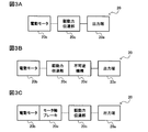
出力端ロック部を備えるEMAについて、図3A~図3Cを参照して説明する。図3A~図3Cに示すブロック図は、第一アクチュエータ21または第二アクチュエータ22として用いられるEMAの機能構成を模式的に示したものである。なお、図3A~図3Cにおいては、第一アクチュエータ21または第二アクチュエータ22として用いられるEMAを、説明の便宜上、EMA20として包括化して示し、第一アクチュエータ21の出力端21aまたは第二アクチュエータ22の出力端22aも、出力端20aとして包括化して示す。
[Configuration example of electro-mechanical actuator (EMA)]
An EMA having an output end lock will be described with reference to FIGS. 3A to 3C. The block diagrams shown in FIGS. 3A to 3C schematically show the functional configuration of EMA used as the first actuator 21 or the second actuator 22. 3A to 3C, the EMA used as the first actuator 21 or the second actuator 22 is comprehensively shown as the EMA 20 for convenience of explanation, and the output end 21a of the first actuator 21 or the second actuator 22 is shown. The output end 22a is also shown comprehensively as the output end 20a.
図3Aに示すEMA20は、出力端20a、電動モータ20b、および駆動力伝達部20cを備える基本的な構成であり、電動モータ20bの回転駆動力が駆動力伝達部20cを介して出力端20aに伝達される。それゆえ、図3Aでは、電動モータ20bと駆動力伝達部20cと出力端20aとを模式的に線分で結んでいる。駆動力伝達部20cの具体的な構成は特に限定されず、EMA20の種類に応じた公知の構成のギア機構等を好適に用いることができる。
The EMA 20 illustrated in FIG. 3A is a basic configuration including an output end 20a, an electric motor 20b, and a driving force transmission unit 20c, and the rotational driving force of the electric motor 20b is transmitted to the output end 20a via the driving force transmission unit 20c. It is transmitted. Therefore, in FIG. 3A, the electric motor 20b, the driving force transmission unit 20c, and the output end 20a are schematically connected by a line segment. The specific configuration of the driving force transmission unit 20c is not particularly limited, and a gear mechanism or the like having a known configuration according to the type of EMA 20 can be suitably used.
EMA20がリニアアクチュエータであれば、駆動力伝達部20cは、電動モータ20bの回転運動を往復運動に変換するギア機構等であればよい。これにより、電動モータ20bの駆動力が駆動力伝達部20cを介して出力端20aに伝達され、出力端20aは進退移動することになる(例えば、第一アクチュエータ21)。また、EMA20がロータリーアクチュエータであれば、駆動力伝達部20cは、電動モータ20bの回転運動(モータ軸における連続的な回転運動)を回動運動(出力端20aにおける回転可能範囲が制限された回転運動)に変換するギア機構等であればよい。これにより、電動モータ20bの駆動力が駆動力伝達部20cを介して出力端20aに伝達され、出力端20aは回動移動することになる(例えば、第二アクチュエータ22)。
If the EMA 20 is a linear actuator, the driving force transmitting unit 20c may be a gear mechanism or the like that converts the rotational movement of the electric motor 20b into a reciprocating movement. Thus, the driving force of the electric motor 20b is transmitted to the output end 20a via the driving force transmission unit 20c, and the output end 20a moves forward and backward (for example, the first actuator 21). When the EMA 20 is a rotary actuator, the driving force transmitting unit 20c rotates the electric motor 20b (continuous rotational movement of the motor shaft) in a rotational movement (a rotatable range at the output end 20a is limited). It may be a gear mechanism or the like that converts it into motion. Thereby, the driving force of the electric motor 20b is transmitted to the output end 20a via the driving force transmission unit 20c, and the output end 20a is rotationally moved (for example, the second actuator 22).
図3Aに示す基本的な構成のEMA20に対して、図3Bに示すEMA20は、駆動力伝達部20cに不可逆機構20dが設けられている構成となっている。不可逆機構20dの具体的な構成は特に限定されず、出力端20aに作用した外力によって当該出力端20aが逆動作しないようにするものであればよい。あるいは、不可逆機構20dは、当該不可逆機構20dとともに駆動力伝達部20cが電動モータのトルク増幅を行う減速機構を兼ねる構成であってもよい。代表的には、不思議遊星歯車またはウォームギア等を挙げることができる。
The EMA 20 shown in FIG. 3B has a configuration in which an irreversible mechanism 20d is provided in the driving force transmission unit 20c, as opposed to the EMA 20 having the basic configuration shown in FIG. 3A. The specific configuration of the irreversible mechanism 20d is not particularly limited as long as the output end 20a does not reversely operate due to the external force acting on the output end 20a. Alternatively, the irreversible mechanism 20d may be configured to double as the irreversible mechanism 20d and also serve as a speed reduction mechanism that amplifies the torque of the electric motor by the driving force transmission unit 20c. As a typical example, there can be mentioned a wonder planet gear or a worm gear.
操縦舵面12に対しては、航空機の飛行中、常時、空力負荷による外力が作用する。しかしながら、操縦舵面12の舵角は、飛行時間の大半において変化しない(舵面作動速度が0)ことが一般的である。本実施の形態1に係る航空機操舵システム10Aにおいて、第一アクチュエータ21または第二アクチュエータ22(もしくはその両方)がEMAであれば、駆動力伝達部20cが不可逆機構20dを備えることで、電動モータ20bに通電しない状態で操縦舵面12すなわち出力端20aに外力が作用しても舵角を保持することが可能になる。それゆえ、舵面作動速度が0である間に不要な電力消費と回避または抑制することができるとともに、電力消費に伴う発熱も回避または抑制することができる。
An external force due to aerodynamic load always acts on the control surface 12 during flight of the aircraft. However, in general, the steering angle of the control surface 12 does not change at most of the flight time (the control surface operating speed is zero). In the aircraft steering system 10A according to the first embodiment, when the first actuator 21 or the second actuator 22 (or both of them) is EMA, the driving force transmission unit 20c includes the irreversible mechanism 20d, whereby the electric motor 20b is provided. The steering angle can be maintained even if an external force is applied to the control surface 12, that is, the output end 20 a in a state where power is not supplied. Therefore, it is possible to avoid unnecessary power consumption and avoidance or suppression while the control surface operating speed is zero, and also to avoid or suppress heat generation associated with the power consumption.
また、EMA20が不可逆機構20dを備えていれば、電動モータ20bにおける必要なトルク量を低減することができる。それゆえ、電動モータ20bとしては、ダイレクトドライブ形式のように大型または高駆動力のものを用いる必要がなくなり、より小型かつ低駆動力のものを採用することが可能になる。その結果、EMA20において、電力消費量のさらなる低減あるいは発熱のさらなる抑制を図ることが可能になる。
Further, if the EMA 20 includes the irreversible mechanism 20d, the amount of torque required for the electric motor 20b can be reduced. Therefore, as the electric motor 20b, it is not necessary to use a large or high driving force motor such as a direct drive type, and it becomes possible to adopt a smaller and low driving force motor. As a result, in the EMA 20, it is possible to further reduce power consumption or further suppress heat generation.
また、図3Aまたは図3Bに示すEMA20に対して、図3Cに示すEMA20は、電動モータ20bにモータ軸ブレーキ20eが設けられている構成となっている。モータ軸ブレーキ20eの具体的な構成は限定されず、電動モータ20bのモータ軸を制動してモータ軸の回転を停止することができるものであればよい。代表的には、電磁ブレーキまたはクラッチブレーキ等を挙げることができる。
In addition to the EMA 20 shown in FIG. 3A or 3B, the EMA 20 shown in FIG. 3C has a configuration in which a motor shaft brake 20e is provided on the electric motor 20b. The specific configuration of the motor shaft brake 20e is not limited, as long as the motor shaft of the electric motor 20b can be braked to stop the rotation of the motor shaft. Typically, an electromagnetic brake or a clutch brake can be mentioned.
EMA20の出力端20aは相対的に高トルクであるが、電動モータ20bのモータ軸は出力端20aに比較すれば低トルクである。前記の通り、トルクサミング形式の冗長構成では、EMAが固着障害により動作不能になったときに、高トルクの出力端20aをフリーにするために切離し装置を設ける必要がある。それゆえ、切離し装置の構成は高トルクに対応するために複雑化かつ重量化するとともに、固着が発生してから駆動力伝達部20cの切り離しが完了するまでにタイムラグが生じる等の課題も考えられる。
Although the output end 20a of the EMA 20 has a relatively high torque, the motor shaft of the electric motor 20b has a low torque as compared to the output end 20a. As mentioned above, in a torque-summing type of redundant configuration, it is necessary to provide a disconnect device to free the high torque output end 20a when the EMA becomes inoperable due to a sticking failure. Therefore, the configuration of the disconnecting device may be complicated and heavy in order to cope with high torque, and there may be a problem such as a time lag between the occurrence of the sticking and the completion of the disconnecting of the driving force transmission unit 20c. .
これに対して、モータ軸ブレーキ20eは、切離し装置に比べて、その構成を簡素化できるとともにその重量の軽減も図ることができる。また、モータ軸ブレーキ20eは、モータ軸を停止させるだけで、出力端20aをロックすることが可能である。そのため、トルクサミング形式における切離し装置のようにタイムラグが生じることがなく、固着障害の発生時であっても相対的に迅速な対応が可能となる。
On the other hand, the motor shaft brake 20e can simplify its structure and reduce its weight as compared with the disconnecting device. The motor shaft brake 20e can lock the output end 20a simply by stopping the motor shaft. Therefore, a time lag does not occur as in the torque-summing type separation device, and relatively quick response is possible even at the time of occurrence of sticking failure.
なお、図3Bまたは図3Cにおいては、出力端ロック部である不可逆機構20dおよびモータ軸ブレーキ20eをそれぞれ独立したブロックとして図示しているが、不可逆機構20dまたはモータ軸ブレーキ20eは、それぞれ駆動力伝達部20cまたは電動モータ20bに対して独立した構成であってもよいし、一体化された構成であってもよい。例えば、不可逆機構20dは駆動力伝達部20cに一体化されたひとつのギア機構等であってもよいし、モータ軸ブレーキ20eはブレーキ付電動モータとして構成されてもよい。また、図示しないが、EMA20は、出力端ロック部として、不可逆機構20dおよびモータ軸ブレーキ20eの双方を備えていてもよい。
In FIG. 3B or FIG. 3C, although the irreversible mechanism 20d and the motor shaft brake 20e which are output end lock parts are illustrated as independent blocks, respectively, the irreversible mechanism 20d or the motor shaft brake 20e transmits the driving force, respectively. The configuration may be independent of or integrated with the unit 20c or the electric motor 20b. For example, the irreversible mechanism 20d may be a single gear mechanism integrated with the driving force transmission unit 20c or the like, or the motor shaft brake 20e may be configured as an electric motor with a brake. Although not shown, the EMA 20 may be provided with both the irreversible mechanism 20d and the motor shaft brake 20e as an output end lock portion.
このように、本開示によれば、翼本体11に設けられる第一アクチュエータ21に加えて、操縦舵面12にもロータリーアクチュエータである第二アクチュエータ22が設けられており、第一アクチュエータ21および第二アクチュエータ22がホーンアーム13を介して連結されている。また、第一アクチュエータ21および第二アクチュエータ22の少なくとも一方がEMA20である。
As described above, according to the present disclosure, in addition to the first actuator 21 provided to the wing main body 11, the control and steering surface 12 is also provided with the second actuator 22 that is a rotary actuator. Two actuators 22 are connected via a horn arm 13. Further, at least one of the first actuator 21 and the second actuator 22 is the EMA 20.
これにより、操縦舵面12は、第一アクチュエータ21および第二アクチュエータ22のいずれによっても駆動することが可能となり、いずれか一方のアクチュエータに固着障害が発生して動作できなくなったとしても、他方のアクチュエータにより操縦舵面12を駆動できるという冗長性を実現することが可能になる。また、このような冗長構成は速度サミング形式であるため、EMA20に対して複雑な機構を設ける必要性がない。それゆえ、より簡素な構成により固着障害に対する冗長性を実現することができるとともに、第一アクチュエータ21および/または第二アクチュエータ22の大型化もしくは重量増加等を回避または抑制することができる。
As a result, the control surface 12 can be driven by either the first actuator 21 or the second actuator 22. Even if a sticking failure occurs in any one of the actuators, the other can not operate. It is possible to realize the redundancy that the control surface 12 can be driven by the actuator. Also, since such a redundant configuration is a speed-summing type, there is no need to provide a complicated mechanism for the EMA 20. Therefore, redundancy with respect to the sticking failure can be realized with a simpler configuration, and enlargement or weight increase of the first actuator 21 and / or the second actuator 22 can be avoided or suppressed.
さらに、前記構成によれば、ロータリーアクチュエータである第二アクチュエータ22は、操縦舵面12のヒンジラインL1に少なくとも平行となるように、当該操縦舵面12に取り付けられている。これにより、第二アクチュエータ22は、実質的に操縦舵面12に一体化されていることになる。操縦舵面12に対しては外気流に曝されるため、第二アクチュエータ22の発熱部位から操縦舵面12への放熱経路を適切に設計することによって、操縦舵面12に一体化された第二アクチュエータ22の効率的な放熱が可能になる。そのため、第二アクチュエータ22の電動モータ20bの電流密度を引き上げることが可能になり、第二アクチュエータ22の小型化(出力重量比の向上)を図ることができる。
Further, according to the configuration, the second actuator 22 which is a rotary actuator is attached to the control surface 12 so as to be at least parallel to the hinge line L1 of the control surface 12. Thus, the second actuator 22 is substantially integrated with the control surface 12. Since the control and control surface 12 is exposed to the outside air flow, the heat radiation region of the second actuator 22 from the heat generation part of the second actuator 22 is appropriately designed to provide a second heat source integrated with the control and control surface 12 Efficient heat dissipation of the two actuators 22 is possible. Therefore, the current density of the electric motor 20b of the second actuator 22 can be increased, and the second actuator 22 can be miniaturized (i.e., the output weight ratio can be improved).
(実施の形態2)
前記実施の形態1に係る航空機操舵システム10Aは、第一アクチュエータ21がリニアアクチュエータであったが、本開示はこれに限定されない。
Second Embodiment
In the aircraft steering system 10A according to the first embodiment, the first actuator 21 is a linear actuator, but the present disclosure is not limited thereto.
図4に示すように、本実施の形態2に係る航空機操舵システム10Bは、前記実施の形態1に係る航空機操舵システム10Aと同様に、第一アクチュエータ23および第二アクチュエータ22を備えており、第二アクチュエータ22は、ロータリーアクチュエータであって、その出力端22aの回動軸線L2がヒンジラインL1と同軸(または平行)になるように操縦舵面12に一体化されている。また、第二アクチュエータ22の出力端22aには、ホーンアーム13の他端が固定されている。ただし、第一アクチュエータ23は、第二アクチュエータ22と同様のロータリーアクチュエータとなっている。
As shown in FIG. 4, the aircraft steering system 10B according to the second embodiment includes the first actuator 23 and the second actuator 22 similarly to the aircraft steering system 10A according to the first embodiment, and The second actuator 22 is a rotary actuator and is integrated with the control surface 12 such that the pivot axis L2 of the output end 22a thereof is coaxial (or parallel) with the hinge line L1. The other end of the horn arm 13 is fixed to the output end 22 a of the second actuator 22. However, the first actuator 23 is a rotary actuator similar to the second actuator 22.
図4では、第一アクチュエータ23の出力端23aは、第二アクチュエータ22の出力端22aと同様に、第一アクチュエータ23本体に隠れて位置するため破線で図示している。また、また、図4に示す構成では、前記実施の形態1と同様に、操縦舵面12のヒンジラインL1と第二アクチュエータ22の回動軸線L2とが一致している(同軸である)。それゆえ、図4では、第二アクチュエータ22の出力端22aには、回動軸線L2は図示せずヒンジラインL1のみ図示しているが、第一アクチュエータ23の出力端23aには、その回動中心である回動軸線L3を図示している。
In FIG. 4, the output end 23 a of the first actuator 23 is illustrated by a broken line because it is located behind the first actuator 23 as in the case of the output end 22 a of the second actuator 22. Further, in the configuration shown in FIG. 4, the hinge line L1 of the control surface 12 and the pivot axis L2 of the second actuator 22 coincide (coaxially) as in the first embodiment. Therefore, although in FIG. 4 the pivot axis L2 is not shown and only the hinge line L1 is shown at the output end 22a of the second actuator 22, the pivoting of the output end 23a of the first actuator 23 The pivoting axis L3 which is the center is illustrated.
航空機操舵システム10Bにおいては、第一アクチュエータ23の出力端23aとホーンアーム13の一端との間は、航空機操舵システム10Aのように直接的に連結されておらず、連結部15を介して間接的に連結されている。連結部15は、図4に示す例では、第一アクチュエータ23の出力端23aに固定される連結用アーム部材24と、当該連結用アーム部材24およびホーンアーム13の一端とを連結するアーム間連結部材25とにより構成されている。
In the aircraft steering system 10B, the output end 23a of the first actuator 23 and one end of the horn arm 13 are not directly coupled as in the aircraft steering system 10A, but indirectly through the coupling portion 15. Is linked to In the example shown in FIG. 4, the connecting portion 15 is an inter-arm connection that connects the connecting arm member 24 fixed to the output end 23 a of the first actuator 23 and one end of the connecting arm member 24 and the horn arm 13. It is constituted by the member 25.
言い換えれば、第一アクチュエータ23の出力端23aには、連結部15を構成する連結用アーム部材24の一端が固定され、連結用アーム部材24の他端には連結部15を構成するアーム間連結部材25の一端が連結され、アーム間連結部材25の他端は、ホーンアーム13の一端の出力端連結部位13aに連結され、ホーンアーム13の他端は第二アクチュエータ22の出力端22aが固定されていることになる。
In other words, one end of the connecting arm member 24 constituting the connecting portion 15 is fixed to the output end 23a of the first actuator 23, and the other end of the connecting arm member 24 is connected between the arms constituting the connecting portion 15 One end of the member 25 is connected, the other end of the inter-arm connecting member 25 is connected to the output end connection portion 13a of one end of the horn arm 13, and the other end of the horn arm 13 is fixed to the output end 22a of the second actuator 22 It will be done.
第一アクチュエータ23とホーンアーム13とを連結する連結部15の構成は、本実施の形態2のように、連結用アーム部材24およびアーム間連結部材25を備える構成に限定されず、公知の他の構成を採用することができる。また、前記実施の形態1では、リニア型の第一アクチュエータ21の出力端21aに対して、ホーンアーム13の一端が直接連結されていたが、本実施の形態2のように、第一アクチュエータ21の出力端21aに対して連結部15を介してホーンアーム13の一端が間接的に連結されてもよい。
The configuration of the connecting portion 15 for connecting the first actuator 23 and the horn arm 13 is not limited to the configuration including the connecting arm member 24 and the inter-arm connecting member 25 as in the second embodiment, The configuration of can be adopted. In the first embodiment, one end of the horn arm 13 is directly connected to the output end 21a of the linear first actuator 21. However, as in the second embodiment, the first actuator 21 is One end of the horn arm 13 may be indirectly connected to the output end 21 a of the second embodiment via the connection portion 15.
第一アクチュエータ23の出力端23aは、前記の通り、回動軸線L3を回動中心としており、図4における双方向矢印M3の方向に回動動作する。また、第二アクチュエータ22の出力端22aは、前記の通り回動軸線L2を回動中心としており、図4における双方向矢印M2の方向に回動動作する。図4では、回動軸線L2および回動軸線L3は紙面方向に沿って延伸しているので、回動軸線L2および回動軸線L3は互いに平行の位置関係にある。それゆえ、回動軸線L3は、ヒンジラインL1に対しても平行の位置関係にある。
As described above, the output end 23a of the first actuator 23 pivots about the pivot axis L3, and pivots in the direction of the bidirectional arrow M3 in FIG. Further, as described above, the output end 22a of the second actuator 22 pivots about the pivot axis L2, and pivots in the direction of the bidirectional arrow M2 in FIG. In FIG. 4, since the rotation axis L2 and the rotation axis L3 extend along the paper surface direction, the rotation axis L2 and the rotation axis L3 are in a positional relationship parallel to each other. Therefore, the pivot axis L3 is also in parallel to the hinge line L1.
第一アクチュエータ23の出力端23aが矢印M3の方向に回動移動すれば、出力端23aに連結される連結部15を介してホーンアーム13に揺動運動が伝達される。さらに、この揺動運動はホーンアーム13を介して操縦舵面12に伝達されるので、第一アクチュエータ23により操縦舵面12が揺動駆動され、舵面角度が変更される。
When the output end 23a of the first actuator 23 is pivotally moved in the direction of the arrow M3, the swinging motion is transmitted to the horn arm 13 via the connecting portion 15 connected to the output end 23a. Furthermore, since this rocking motion is transmitted to the control and control surface 12 via the horn arm 13, the control and control surface 12 is driven to rock by the first actuator 23, and the control surface angle is changed.
ここで、第一アクチュエータ23および第二アクチュエータ22のいずれもEMAであり、このうち第一アクチュエータ23に固着障害(ジャミング)が発生したと仮定する。従来の一般的な構成では、ホーンアーム13の一端は操縦舵面12に直接取り付けられているので、第一アクチュエータ23が動作できなければ、操縦舵面12を駆動することができない。
Here, it is assumed that both the first actuator 23 and the second actuator 22 are EMA, and among these, the sticking failure (jamming) occurs in the first actuator 23. In the conventional general configuration, since one end of the horn arm 13 is directly attached to the control surface 12, the control surface 12 can not be driven unless the first actuator 23 can operate.
これに対して、本開示においては、操縦舵面12には、出力端22aがヒンジラインL1に一致するようにロータリー型の第二アクチュエータ22が取り付けられている。それゆえ、第二アクチュエータ22が回動動作することにより操縦舵面12を揺動駆動することができる。したがって、本実施の形態2に係る航空機操舵システム10Bにおいても、速度サミング形式の冗長構成を実現することができる。なお、本実施の形態2においても、第一アクチュエータ23および第二アクチュエータ22の双方がEMAでなくてもよく、少なくとも一方がEMAであればよいことはいうまでもない。
On the other hand, in the present disclosure, the rotary type second actuator 22 is attached to the control surface 12 so that the output end 22a coincides with the hinge line L1. Therefore, when the second actuator 22 rotates, the control and control surface 12 can be rocked and driven. Therefore, also in the aircraft steering system 10B according to the second embodiment, a redundant configuration of the speed summing type can be realized. In the second embodiment, it is needless to say that both of the first actuator 23 and the second actuator 22 may not be EMA, and at least one may be EMA.
なお、本実施の形態2に係る航空機操舵システム10Bの構成は、第一アクチュエータ23がロータリー型であり前述したような連結部15を備える以外は、前記実施の形態1に係る航空機操舵システム10Aの構成と同様であり、各構成の作用も同様であるので、その具体的な説明は省略する。
The configuration of the aircraft steering system 10B according to the second embodiment is the same as that of the aircraft steering system 10A according to the first embodiment except that the first actuator 23 is a rotary type and includes the connecting portion 15 as described above. The configuration is the same as that of the configuration, and the operation of each configuration is also the same.
本実施の形態2においても、操縦舵面12は、第一アクチュエータ23および第二アクチュエータ22のいずれによっても駆動することが可能となり、いずれか一方のアクチュエータに固着障害が発生して動作できなくなったとしても、他方のアクチュエータにより操縦舵面12を駆動できるという冗長性を実現することが可能になる。また、第一アクチュエータ23および第二アクチュエータ22による冗長構成は速度サミング形式であるため、これらがEMAであっても複雑な機構を設ける必要性がない。それゆえ、より簡素な構成により冗長性を実現することができるとともに、EMAの大型化もしくは重量増加等を回避または抑制することができる。
Also in the second embodiment, the control surface 12 can be driven by any of the first actuator 23 and the second actuator 22 and a sticking failure occurs in either one of the actuators and the operation becomes impossible. Also, it is possible to realize the redundancy that the control surface 12 can be driven by the other actuator. In addition, since the redundant configuration by the first actuator 23 and the second actuator 22 is a velocity summing type, there is no need to provide a complicated mechanism even if they are EMA. Therefore, redundancy can be realized by a simpler configuration, and enlargement or weight increase of the EMA can be avoided or suppressed.
また、本実施の形態2においても、前記実施の形態1と同様に、ロータリーアクチュエータである第二アクチュエータ22は、操縦舵面12のヒンジラインL1に少なくとも平行となるように、当該操縦舵面12に一体的に取り付けられている。そのため、第二アクチュエータ22の効率的な放熱が可能になり、第二アクチュエータ22の小型化(出力重量比の向上)を図ることができる。
Also in the second embodiment, as in the first embodiment, the control surface 12 is controlled so that the second actuator 22 which is a rotary actuator is at least parallel to the hinge line L1 of the control surface 12. Integrally attached to the Therefore, efficient heat dissipation of the second actuator 22 becomes possible, and downsizing (improvement of output weight ratio) of the second actuator 22 can be achieved.
このように、本開示においては、前記実施の形態1に係る航空機操舵システム10Aのように第一アクチュエータ21がリニアアクチュエータであってもよいし、本実施の形態2に係る航空機操舵システム10Bのように第一アクチュエータ23がロータリーアクチュエータであってもよい。
Thus, in the present disclosure, as in the aircraft steering system 10A according to the first embodiment, the first actuator 21 may be a linear actuator, and as in the aircraft steering system 10B according to the second embodiment, The first actuator 23 may be a rotary actuator.
言い換えれば、本開示においては、前記実施の形態1に係る航空機操舵システム10Aであっても、本実施の形態2に係る航空機操舵システム10Bであっても、従来のように、翼本体11に取り付けられる第一アクチュエータ21そのものに対して冗長構成を設けるのではなく、冗長化の発想を転換することにより、操縦舵面12にロータリー型の第二アクチュエータ22を一体的に設けて、この第二アクチュエータ22によりホーンアーム13を動作可能としている。それゆえ、本開示によれば、簡素な構成で速度サミング形式での冗長化が可能であるとともに、前述したように、EMAの小型化や重量増加の回避または抑制を図ることができる。
In other words, in the present disclosure, even if it is the aircraft steering system 10A according to the first embodiment or the aircraft steering system 10B according to the second embodiment, it is attached to the wing body 11 as in the related art. The second actuator 22 of the rotary type is integrally provided on the control and control surface 12 by changing the concept of redundancy instead of providing the redundant configuration for the first actuator 21 itself. 22 makes the horn arm 13 operable. Therefore, according to the present disclosure, redundancy can be achieved in a speed-summing format with a simple configuration, and as described above, downsizing or weight increase of EMA can be avoided or suppressed.
このように、本開示に係る航空機操舵システムは、航空機の翼本体および操縦舵面と、前記翼本体に取り付けられる第一アクチュエータと、前記第一アクチュエータの出力を前記操縦舵面に伝達する舵面アーム部材と、を備えるとともに、さらに、ロータリーアクチュエータであって、前記操縦舵面に取り付けられる第二アクチュエータと、を備え、前記第一アクチュエータおよび前記第二アクチュエータの少なくとも一方が電気機械式アクチュエータであり、前記舵面アーム部材は、その一端が前記第一アクチュエータの出力端に直接または間接的に連結されているとともに、その他端が前記第二アクチュエータの出力端に固定されており、前記第二アクチュエータは、その出力端の回動軸線が前記操縦舵面の支点軸線に平行または一致するように当該操縦舵面に一体的に取り付けられている構成である。
Thus, an aircraft steering system according to the present disclosure includes a wing body and a control and control surface of an aircraft, a first actuator attached to the wing body, and a control surface transmitting the output of the first actuator to the control and control surface. An arm member, and a rotary actuator, further comprising a second actuator attached to the control surface, at least one of the first actuator and the second actuator being an electro-mechanical actuator The control surface arm member has one end directly or indirectly connected to the output end of the first actuator and the other end fixed to the output end of the second actuator, and the second actuator The rotation axis of its output end is parallel to or coincident with the fulcrum axis of the control surface A structure that is integrally attached to the control surfaces to so that.
前記構成によれば、翼本体に設けられる第一アクチュエータに加えて、操縦舵面にもロータリーアクチュエータである第二アクチュエータが設けられており、第一アクチュエータおよび第二アクチュエータが舵面アーム部材(ホーンアーム)を介して連結されている。また、第一アクチュエータおよび第二アクチュエータの少なくとも一方が電気機械式アクチュエータ(EMA)である。
According to the above configuration, in addition to the first actuator provided to the wing main body, the second actuator that is a rotary actuator is also provided to the control and control surface, and the first actuator and the second actuator are the control surface arm members (horn It is connected via an arm). In addition, at least one of the first actuator and the second actuator is an electro-mechanical actuator (EMA).
これにより、操縦舵面は、第一アクチュエータおよび第二アクチュエータのいずれによっても駆動することが可能となり、いずれか一方のアクチュエータに固着障害が発生して動作できなくなったとしても、他方のアクチュエータにより操縦舵面を駆動できるという冗長性を実現することが可能になる。また、このような冗長構成は、2台のアクチュエータを直列に連結することで速度サミング形式の冗長化を行っていることになるため、各々のアクチュエータに対して複雑な機構を設ける必要性がない。それゆえ、より簡素な構成により固着障害に対する冗長性を実現することができるとともに、アクチュエータの大型化または重量増加等を回避または抑制することができる。
As a result, the control and control surface can be driven by either the first actuator or the second actuator, and even if a sticking failure occurs in either one of the actuators and the operation becomes impossible, the other actuator controls the operation. It is possible to realize the redundancy that the control surface can be driven. In addition, since such a redundant configuration performs speed-summing type redundancy by connecting two actuators in series, there is no need to provide a complicated mechanism for each actuator. . Therefore, redundancy with respect to sticking failure can be realized by a simpler configuration, and enlargement or weight increase of the actuator can be avoided or suppressed.
さらに、前記構成によれば、ロータリーアクチュエータである第二アクチュエータは、操縦舵面の支点軸線(ヒンジライン)に少なくとも平行となるように、操縦舵面に取り付けられている。これにより、第二アクチュエータは、実質的に操縦舵面に一体化されていることになる。操縦舵面に対しては外気流に曝されるため、この外気流により、操縦舵面に一体化された第二アクチュエータの効率的な放熱が可能になる。そのため、第二アクチュエータの電動モータの電流密度を引き上げることが可能になり、第二アクチュエータの小型化(出力重量比の向上)を図ることができる。
Further, according to the above configuration, the second actuator, which is a rotary actuator, is attached to the control and control surface so as to be at least parallel to the fulcrum axis (hinge line) of the control and control surface. Thus, the second actuator is substantially integrated with the control surface. Since the control surface is exposed to the external air flow, the external air flow enables efficient heat dissipation of the second actuator integrated in the control surface. Therefore, the current density of the electric motor of the second actuator can be increased, and the second actuator can be miniaturized (the output weight ratio can be improved).
前記構成の航空機操舵システムにおいては、前記第一アクチュエータがリニアアクチュエータであり、前記舵面アーム部材の一端は当該第一アクチュエータの出力端に対して直接連結されている構成であってもよい。
In the aircraft steering system configured as described above, the first actuator may be a linear actuator, and one end of the control surface arm member may be directly connected to the output end of the first actuator.
また、前記構成の航空機操舵システムにおいては、前記第一アクチュエータがロータリーアクチュエータであり、前記舵面アーム部材の一端は、前記第一アクチュエータの出力端に対して、連結部を介して間接的に連結されている構成であってもよい。
Further, in the aircraft steering system configured as described above, the first actuator is a rotary actuator, and one end of the control surface arm member is indirectly connected to the output end of the first actuator through a connecting portion. The configuration may be adopted.
また、前記構成の航空機操舵システムにおいては、前記連結部は、前記第一アクチュエータの前記出力端に固定される連結用アーム部材と、当該連結用アーム部材および前記舵面アーム部材の一端を連結するアーム間連結部材と、を備えている構成であってもよい。
Further, in the aircraft steering system configured as described above, the connecting portion connects the connecting arm member fixed to the output end of the first actuator, and the connecting arm member and one end of the control surface arm member. An inter-arm connection member may be provided.
また、前記構成の航空機操舵システムにおいては、前記第二アクチュエータが電気機械式アクチュエータである構成であってもよい。
Further, in the aircraft steering system configured as described above, the second actuator may be an electromechanical actuator.
また、前記構成の航空機操舵システムにおいては、前記電気機械式アクチュエータは、その出力端の動作をロックする出力端ロック部を備えている構成であってもよい。
Further, in the aircraft steering system having the above configuration, the electromechanical actuator may be configured to include an output end lock portion that locks the operation of the output end.
なお、本発明は前記実施の形態の記載に限定されるものではなく、特許請求の範囲に示した範囲内で種々の変更が可能であり、異なる実施の形態や複数の変形例にそれぞれ開示された技術的手段を適宜組み合わせて得られる実施の形態についても本発明の技術的範囲に含まれる。
The present invention is not limited to the description of the above-described embodiment, but various modifications can be made within the scope of the claims, and the present invention is disclosed in different embodiments and plural modifications. Embodiments obtained by appropriately combining the technical means are also included in the technical scope of the present invention.
また、上記説明から、当業者にとっては、本発明の多くの改良や他の実施形態が明らかである。従って、上記説明は、例示としてのみ解釈されるべきであり、本発明を実行する最良の態様を当業者に教示する目的で提供されたものである。本発明の精神を逸脱することなく、その構造及び/又は機能の詳細を実質的に変更できる。
Also, from the above description, many modifications and other embodiments of the present invention will be apparent to those skilled in the art. Accordingly, the above description should be taken as exemplary only, and is provided for the purpose of teaching those skilled in the art the best mode of carrying out the present invention. The structural and / or functional details may be substantially altered without departing from the spirit of the present invention.