WO2019017232A1 - スプリングシートおよび軸受装置 - Google Patents
スプリングシートおよび軸受装置 Download PDFInfo
- Publication number
- WO2019017232A1 WO2019017232A1 PCT/JP2018/025942 JP2018025942W WO2019017232A1 WO 2019017232 A1 WO2019017232 A1 WO 2019017232A1 JP 2018025942 W JP2018025942 W JP 2018025942W WO 2019017232 A1 WO2019017232 A1 WO 2019017232A1
- Authority
- WO
- WIPO (PCT)
- Prior art keywords
- spring seat
- spring
- drainage
- bearing
- coil spring
- Prior art date
- Legal status (The legal status is an assumption and is not a legal conclusion. Google has not performed a legal analysis and makes no representation as to the accuracy of the status listed.)
- Ceased
Links
Images



Classifications
-
- B—PERFORMING OPERATIONS; TRANSPORTING
- B60—VEHICLES IN GENERAL
- B60G—VEHICLE SUSPENSION ARRANGEMENTS
- B60G15/00—Resilient suspensions characterised by arrangement, location or type of combined spring and vibration damper, e.g. telescopic type
- B60G15/02—Resilient suspensions characterised by arrangement, location or type of combined spring and vibration damper, e.g. telescopic type having mechanical spring
- B60G15/06—Resilient suspensions characterised by arrangement, location or type of combined spring and vibration damper, e.g. telescopic type having mechanical spring and fluid damper
- B60G15/07—Resilient suspensions characterised by arrangement, location or type of combined spring and vibration damper, e.g. telescopic type having mechanical spring and fluid damper the damper being connected to the stub axle and the spring being arranged around the damper
-
- F—MECHANICAL ENGINEERING; LIGHTING; HEATING; WEAPONS; BLASTING
- F16—ENGINEERING ELEMENTS AND UNITS; GENERAL MEASURES FOR PRODUCING AND MAINTAINING EFFECTIVE FUNCTIONING OF MACHINES OR INSTALLATIONS; THERMAL INSULATION IN GENERAL
- F16C—SHAFTS; FLEXIBLE SHAFTS; ELEMENTS OR CRANKSHAFT MECHANISMS; ROTARY BODIES OTHER THAN GEARING ELEMENTS; BEARINGS
- F16C17/00—Sliding-contact bearings for exclusively rotary movement
- F16C17/04—Sliding-contact bearings for exclusively rotary movement for axial load only
-
- F—MECHANICAL ENGINEERING; LIGHTING; HEATING; WEAPONS; BLASTING
- F16—ENGINEERING ELEMENTS AND UNITS; GENERAL MEASURES FOR PRODUCING AND MAINTAINING EFFECTIVE FUNCTIONING OF MACHINES OR INSTALLATIONS; THERMAL INSULATION IN GENERAL
- F16F—SPRINGS; SHOCK-ABSORBERS; MEANS FOR DAMPING VIBRATION
- F16F9/00—Springs, vibration-dampers, shock-absorbers, or similarly-constructed movement-dampers using a fluid or the equivalent as damping medium
- F16F9/32—Details
- F16F9/54—Arrangements for attachment
Definitions
- the present invention relates to a bearing device for supporting a load of a vehicle body applied to a suspension having a shock absorber and a coil spring, and more particularly to a spring seat of the bearing device which functions as a spring seat of the coil spring.
- a strut type suspension (MacPherson strut) used for a front wheel of an automobile includes a shock absorber and a coil spring disposed around the shock absorber, and the coil spring attaches the strut type suspension to the vehicle body by a steering operation.
- a thrust bearing device is usually disposed between the upper mount and the coil spring in order to support the load applied to the strut type suspension while allowing the relative rotation smoothly.
- Patent Document 1 discloses, as a thrust bearing device for a strut type suspension, bearings such as rolling bearings and sliding bearings, and a synthetic resin spring seat (cup) functioning as a spring seat of a coil spring.
- the spring seat forms an upper surface including a contact portion with the lower surface of the bearing, a lower surface including an annular support portion supporting the upper end portion of the coil spring, and an annular support portion.
- an annular folded portion forming a cylindrical receiving portion for receiving the upper end portion of the rubber bump stopper inside the portion.
- a discharge orifice for discharging the liquid accumulated on the upper surface side to the lower surface side is formed in the folded portion.
- the upper surface of the bump stopper is accommodated inside the folded portion, and the lower surface including the annular supporting portion for supporting the upper portion of the coil spring is disposed outside the folded portion. Because of this structure, a large load is applied to the folded portion. For this reason, it is necessary to reduce the inner diameter of the discharge orifice to ensure the strength of the folded portion. However, if the inner diameter of the discharge orifice is reduced, the dischargeability of the liquid accumulated on the upper surface side of the spring seat may be reduced, which may affect the sliding performance of the bearing.
- the present invention has been made in view of the above-mentioned circumstances, and an object thereof is to provide a spring seat and a bearing device capable of discharging the liquid accumulated on the upper surface side while maintaining the strength.
- an annular protrusion surrounding the upper surface is provided on the outer edge side of the upper surface, and the drainage drains the liquid accumulated on the upper surface to the outside.
- a road was provided.
- the drainage channel may be slit-like or orifice-like.
- the spring seat of the present invention is A synthetic resin spring seat which functions as a spring seat of the coil spring of a suspension having a shock absorber and a coil spring, An upper surface located on an upper mount side for attaching the suspension to a vehicle body; A lower surface located on the coil spring side; A support formed on the lower surface and supporting an upper end of the coil spring; An annular projection formed on the outer edge side of the upper surface and surrounding the upper surface; And a drainage path communicating with the inner peripheral surface and the outer peripheral surface of the projection and draining the liquid accumulated on the upper surface to the outside.
- the bearing device of the present invention is A bearing device for supporting a load applied to a suspension having a shock absorber and a coil spring, comprising: Said spring seat, It has an upper mount for attaching the suspension to a vehicle body and a bearing disposed between the spring seat and allowing relative rotation of the spring seat relative to the upper mount.
- the annular projection which functions as a reinforcing rib is formed on the outer edge side of the upper surface and the drainage path is provided on this projection, the supporting portion to which a large load is applied is not provided with the drainage orifice.
- the liquid accumulated on the upper surface can be drained to the outside. Therefore, according to the present invention, the liquid accumulated on the upper surface side can be discharged while maintaining the strength.
- FIG. 1 (A), 1 (B) and 1 (C) are a plan view, a bottom view and a front view of a bearing device 1 according to an embodiment of the present invention
- FIG. 1 (D) is FIG. 2 is a cross-sectional view of the bearing device 1 shown in FIG. 2 (A) and 2 (B) are a plan view and a bottom view of the spring seat 2
- FIGS. 2 (C) to 2 (E) are BB of the spring seat 2 shown in FIG. 2 (A). They are a cross-sectional view, a CC cross-sectional view, and a DD cross-sectional view.
- 3 (A), 3 (B) and 3 (C) are a plan view, a bottom view and a front view of the sliding bearing 3, and FIG.
- FIG. 3 (D) is a sliding bearing shown in FIG. 3 (A).
- FIG. 7 is an enlarged cross-sectional view of line E-E of FIG.
- FIG. 4 is a schematic cross-sectional view of a strut type suspension 4 to which a bearing device 1 according to an embodiment of the present invention is applied.
- FIG. 5 (A) is a plan view of a first modification 2A of the spring seat 2
- FIG. 5 (B) is a plan view of a second modification 2B of the spring seat 2.
- FIG. 6A is a plan view of a third modification 2C of the spring seat 2
- FIG. 6B is a plan view of a fourth modification 2D of the spring seat 2.
- FIG. 5 (A) is a plan view of a first modification 2A of the spring seat 2
- FIG. 5 (B) is a plan view of a second modification 2B of the spring seat 2.
- FIG. 6A is a plan view of a third modification 2C of the spring seat 2
- FIG. 1 (A), FIG. 1 (B) and FIG. 1 (C) are a plan view, a bottom view and a front view of the bearing device 1 according to the present embodiment, and FIG. FIG. 2 is a cross-sectional view of the bearing device 1 shown in FIG.
- the bearing device 1 is a device for supporting a load applied to the strut type suspension 4 (see FIG. 4) while allowing rotation around the axis, and as shown in FIG. And a sliding bearing 3 mounted on the spring seat 2.
- FIGS. 2 (C) to 2 (E) are BB of the spring seat 2 shown in FIG. 2 (A). They are a cross-sectional view, a CC cross-sectional view, and a DD cross-sectional view.
- the spring sheet 2 is formed of a high strength thermoplastic resin such as a polyamide resin containing glass, and as shown in the drawing, the upper surface 20 including the annular mounting surface 200 on which the sliding bearing 3 is mounted, and the strut type suspension 4
- the lower surface 21 includes an annular support surface 210 supporting the upper end of the coil spring 42 (see FIG. 4), and the lower surface 21 is formed to receive the upper end of the bump stopper 43 (see FIG. 4) of the strut type suspension 4.
- a cylindrical housing portion 22 is provided.
- a mounting hole 23 for mounting a lower case 31 described later of the slide bearing 3 is formed through the lower surface 21 so that the housing portion 22 and the axial center O coincide with each other.
- the inner peripheral surface 230 of the mounting hole 23 has a guide groove 231 having a constant groove depth d1 along the axial center O, and a tapered guide whose groove depth d2 decreases as going from the upper surface 20 side to the lower surface 21 side.
- a plurality of grooves 232 are alternately formed at equal intervals in the circumferential direction.
- a rotation stop 314 of the lower case 31 of the slide bearing 3 described later is inserted.
- the lower case 31 is fixed to the spring seat 2 by the rotation stopper 314 inserted in the tapered guide groove 232 becoming a part of the tapered guide groove 232, and the space between the spring seat 2 and the slide bearing 3 is fixed. It is possible to prevent the generation of abnormal noise due to rattling.
- reference numerals are given only to some of the guide grooves 231 and the tapered guide grooves 232.
- a plurality of inward protruding protrusions 222 are formed on the inner circumferential surface 221 of the housing 22 at equal intervals in the circumferential direction.
- the protrusion 222 presses the bump stopper 43 accommodated in the accommodation portion 22 radially inward and fixes it.
- window holes 207 are formed in the upper surface 20 corresponding to the individual projections 222 to receive the projections 222 in a frame on an imaginary plane perpendicular to the axial center O.
- annular protrusion 201 surrounding the upper surface 20 is formed on the outer edge side of the upper surface 20.
- the annular projection 201 communicates with the inner circumferential surface 202 and the outer circumferential surface 203 of the annular projection 201 to divide the annular projection 201 and drain the liquid accumulated on the upper surface 20 to the outside, 204 b are alternately arranged at equal intervals in the circumferential direction.
- symbol is attached
- the drainage slits 204a, 204b have buffer flow paths 205a, 205b formed along the directions P, Q intersecting the radial direction.
- the buffer channels 205a and 205b of the drainage slits 204a and 204b have different directions P and Q from each other. Specifically, the directions P and Q of the two intersect. Therefore, when the direction of the high pressure water entering the drainage slits 204a and 204b from the outside is close to one of the directions P and Q of the buffer flow channels 205a and 205b during high pressure cleaning of the vehicle, the direction of the high pressure water is It is the direction that intersects the other. Therefore, the momentum of the water can be reduced regardless of the direction of the water entering the drainage slits 204a and 204b.
- the bottom surface 206 of the drainage slits 204a and 204b is connected to the upper surface 20 on the inner edge side, and is inclined radially outward from the lower surface 21 side from there. Therefore, even when the bearing device 1 is attached to the vehicle body so that the axial center O of the bearing device 1 is vertical (see FIG. 4), the liquid accumulated on the upper surface 20 can be more reliably drained from the drainage slits 204a and 204b. .
- FIG. 3 (A), 3 (B) and 3 (C) are a plan view, a bottom view and a front view of the sliding bearing 3, and FIG. 3 (D) is a sliding bearing shown in FIG. 3 (A).
- FIG. 7 is an enlarged cross-sectional view of line E-E of FIG.
- the slide bearing 3 has a tubular shape in which the annular upper case 30 and the piston rod 40 of the shock absorber 41 constituting the strut type suspension 4 are inserted, and is rotatably combined with the upper case 30.
- the upper case 30 is formed of a high strength thermoplastic resin such as a polyamide resin containing glass, and the upper surface 300 thereof is a mounting surface 301 to the upper mount 5 (see FIG. 4) for mounting the strut type suspension 4 to the vehicle body. Is formed.
- a mounting hole 303 for mounting the metal washer 33 is formed in the lower surface 302 of the upper case 30 so as to penetrate the upper surface 300, and the upper surface 330 of the metal washer 33 is formed around the mounting hole 303 of the lower surface 302.
- An annular lower surface 304 is formed in contact therewith.
- Lower case 31 the piston rod 40 of the shock absorber 41 constituting the strut type suspension 4 is inserted.
- Lower case 31 is formed of a thermoplastic resin having excellent sliding characteristics, such as polyacetal resin impregnated with lubricating oil if necessary, and annular upper surface 311 on which center plate 32 is mounted on the upper end surface 310. Is formed.
- a flange portion 313 is formed which comes into contact with the mounting surface 200 of the upper surface 20 of the spring seat 2 when the slide bearing 3 is mounted on the spring seat 2.
- the slide bearing 3 is mounted on the spring seat 2 on the outer peripheral surface 312, it is inserted into the guide groove 231 or the tapered guide groove 232 formed on the inner peripheral surface 230 of the mounting hole 23 of the spring seat 2.
- a plurality of detents 314 are formed at equal intervals in the circumferential direction.
- the center plate 32 is formed of a resin having excellent sliding characteristics, such as polyethylene and thermoplastic polyester elastomer, and is disposed between the annular lower surface 304 of the upper case 30 and the annular upper surface 311 of the lower case 31. Thereby, the upper case 30 and the lower case 31 relatively rotate via the center plate 32.
- a resin having excellent sliding characteristics such as polyethylene and thermoplastic polyester elastomer
- the metal washer 33 is disposed between the annular lower surface 304 of the upper case 30 and the upper surface 320 of the center plate 32, and the piston rod 40 of the shock absorber 41 constituting the strut type suspension 4 is inserted.
- the metal washer 33 is formed of a steel plate such as steel or stainless steel, or a non-ferrous alloy plate such as a copper alloy or a titanium alloy, and the cylindrical boss portion 331 attached to the mounting hole 303 of the upper case 30 is formed on the upper surface 330 thereof. Is formed.
- FIG. 4 is a schematic cross-sectional view of a strut type suspension 4 to which the bearing device 1 according to the present embodiment is applied.
- the bearing device 1 is attached to, for example, a strut type suspension 4 of an automobile including a shock absorber 41 and a coil spring 42 disposed around the shock absorber 41.
- the strut type suspension 4 to which the bearing device 1 is attached is attached to the vehicle body (not shown) via the upper mount 5.
- the shock absorber 41 includes a piston rod 40 and a bump stopper 43 arranged to surround the piston rod 40.
- the upper mount 5 is made of an elastic member 50 such as rubber in which a core metal 51 is embedded, and accommodates the slide bearing 3 in contact with the mounting surface 301 of the upper case 30 of the slide bearing 3.
- the bearing device 1 including the spring seat 2 and the slide bearing 3 is disposed between the upper mount 5 and the coil spring 42, and in a state where the piston rod 40 is inserted into the slide bearing 3, the support surface 210 of the spring seat 2 While supporting the upper end portion of the coil spring 42, the accommodation portion 22 of the spring seat 2 accommodates the upper end portion of the bump stopper 43.
- the piston rod 40 is integrally formed with the large diameter portion 400 inserted into the lower case 31 of the slide bearing 3 and the large diameter portion 400, and is inserted into the metal washer 33.
- the small diameter portion smaller than the large diameter portion 400 And a threaded portion 402 formed in the small diameter portion 401.
- the large diameter portion 400 of the piston rod 40 rotatably contacts the inner circumferential surface 315 of the lower case 31 in the circumferential direction R.
- a nut 6 is screwed into the threaded portion 402 of the small diameter portion 401 of the piston rod 40.
- the nut 6 is screwed into the screw portion 402 and fixed to the piston rod 40, and is accommodated in the upper mount 5 so as not to rotate in the circumferential direction R with respect to the upper mount 5.
- the metal washer 33 of the slide bearing 3 is held between the step surface 403 formed between the large diameter portion 400 and the small diameter portion 401 of the piston rod 40 and the nut 6 screwed to the screw portion 402. There is.
- the upper case 30 is pushed to the upper mount 5 by the metal washer 33 fixed to the stepped surface 403 of the piston rod 40 by the strut type suspension 4 being attached to the upper mount 5 via the slide bearing 3. It is applied. Thus, relative rotation between the upper case 30 and the metal washer 33 is prevented, and the upper case 30 is held by the upper mount 5 so as not to rotate in the circumferential direction R with respect to the piston rod 40.
- lower case 31 is mounted on spring seat 2 in a state where relative rotation between lower case 31 and spring seat 2 is blocked, and rotates in the circumferential direction R along spring seat 2.
- the spring seat 2 supporting the coil spring 42 and the lower case 31 of the slide bearing 3 are also coil springs. 42 rotates in the circumferential direction R together with 42.
- the metal washer 33 and the upper case 30 of the slide bearing 3 are held by the upper mount 5 so as not to rotate in the circumferential direction R with respect to the piston rod 40.
- the metal washer A relative rotation in the circumferential direction R occurs between the lower case 33 and the upper case 30 and the lower case 31.
- the relative rotation is smoothly performed by the center plate 32 disposed between the annular upper surface 311 of the lower case 31 and the metal washer 33, whereby the steering operation is also performed without resistance.
- the bearing device 1 allows the spring seat 2 to move the strut type suspension 4 through the coil spring 42 while allowing the sliding bearing 3 to turn the coil spring 42 in the circumferential direction R with respect to the upper mount 5. Support the applied vehicle load.
- an annular protrusion 201 functioning as a reinforcing rib is formed, and the annular protrusion 201 drains the liquid accumulated on the upper surface 20 to the outside. Drainage slits 204a and 204b are provided.
- the upper end portion of the bump stopper 43 is accommodated inside the accommodation portion 22, and the lower surface 21 including the annular support surface 210 supporting the upper end portion of the coil spring 42 is disposed outside the accommodation portion 22. Due to the structure, a large load is applied to the housing portion 22.
- the top surface is not provided with a drainage orifice in the housing portion 22.
- the liquid accumulated in 20 can be drained to the outside. Therefore, the liquid accumulated on the upper surface 20 can be discharged while maintaining the strength.
- the drainage slits 204a, 204b are provided with buffer flow paths 205a, 205b formed along the directions P, Q intersecting with the radial direction of the spring seat 2.
- the drainage slits 204a and 204b are alternately arranged in the circumferential direction, and the direction P of the buffer channel 205a of the drainage slit 204a and the direction Q of the buffer channel 205b of the drainage slit 204b are set. It is different. Specifically, the directions P and Q of the two are crossed.
- the bottom surfaces 206 of the drainage slits 204a and 204b are connected to the upper surface 20 on the inner edge side, and are inclined radially outward from there to the lower surface 21 side. Therefore, even when the bearing device 1 is attached to the vehicle body so that the axial center O of the bearing device 1 is vertical (see FIG. 4), the liquid accumulated on the upper surface 20 is more reliably drained from the drainage slits 204a and 204b. be able to.
- the bump stopper 43 housed in the housing portion 22 is fixed by the projection 222 provided on the inner peripheral surface 221 of the housing portion 22. It is not necessary to set the inner diameter of 22 to the outer diameter of the bump stopper 43 over the entire circumference. Therefore, the pressure required for inserting the upper end of the bump stopper 43 into the housing portion 22 of the spring seat 2 is lowered to reduce resistance as compared with the case where the inner diameter of the housing portion 22 is set to the entire circumference. It can be made smaller. Therefore, the workability of the mounting operation to the bump stopper 43 can be improved.
- the inner circumferential surface 230 of the mounting hole 23 goes from the upper surface 20 side to the lower surface 21 side along the axial center O.
- a plurality of tapered guide grooves 232 in which the groove depth d2 becomes shallow in accordance with the circumferential direction are alternately provided at equal intervals in the circumferential direction, and the lower case 31 of the sliding bearing 3 is rotated in these guide grooves 231 and tapered guide grooves 232.
- a stop 314 is inserted.
- the lower case 31 is fixed to the spring seat 2 by the rotation stopper 314 inserted in the tapered guide groove 232 becoming a part of the tapered guide groove 232, and the space between the spring seat 2 and the slide bearing 3 is fixed. It is possible to prevent the generation of abnormal noise due to rattling.
- the spring seat 2 of the present embodiment unlike the spring seat described in Patent Document 1, since the annular folded portion is not provided, the strength of the spring seat 2 can be improved.
- the bottom surfaces 206 of the drainage slits 204a and 204b of the spring sheet 2 are connected to the upper surface 20 on the inner edge side, and are inclined radially outward from the lower surface 21 side.
- the bottom surfaces 206 of the drainage slits 204 a and 204 b may not be inclined radially outward toward the lower surface 21. It may be located on the same plane as the upper surface 20 or on the lower surface 21 side of the upper surface 20.
- the upper surface 20 may be inclined radially outward from the inside toward the lower surface 21 side.
- the bottom surfaces 206 of the drainage slits 204 a and 204 b are formed on the same plane as the inclined upper surface 20.
- the drainage slit 204b having the buffer flow passage 205b formed along the direction Q different from that in the first embodiment is alternately arranged in the circumferential direction on the annular projection 201 of the spring seat 2.
- the drainage slit may communicate with the inner peripheral surface 202 and the outer peripheral surface 203 of the annular projection 201 to divide the annular projection 201 and drain the liquid accumulated on the upper surface 20 to the outside.
- FIG. 5A is a plan view of a first modification 2A of the spring seat 2.
- the drainage slits 204c and 204d have buffer flow channels 205c and 205d formed in the circumferential direction. Thereby, even when high pressure water directed radially inward from outside penetrates into the drainage slits 204c, 204d in high pressure cleaning of a vehicle, the entering high pressure water is made to collide with the wall surface of the buffer flow paths 205c, 205d, It can weaken the force of infiltrating water.
- FIG. 5B is a plan view of a second modification 2B of the spring seat 2.
- a difference of this modification 2B from the spring sheet 2 shown in FIG. 2 is that a drainage slit 204e is provided in the annular projection 201 instead of the drainage slits 204a and 204b.
- the other configuration is the same as that of the spring seat 2 shown in FIG.
- a plurality of drainage slits 204e are formed in an annular buffer flow channel 205e formed in the circumferential direction, and a plurality of drainage slits 208 are disposed in the circumferential direction and communicate with the outer peripheral surface 203 of the annular protrusion 201 and the buffer flow channel 205e.
- a plurality of inlet ports 209 are provided and communicate with the inner circumferential surface 202 of the annular projection 201 and the buffer channel 205 e.
- symbol is attached only to the one part drain outlet 208 and the inflow port 209. As shown in FIG.
- FIG. 6A is a plan view of a third modification 2C of the spring seat 2.
- a difference of this modification 2C from the spring sheet 2 shown in FIG. 2 is that instead of the drainage slits 204a and 204b, drainage slits 204f are arranged in the annular projection 201 at equal intervals in the circumferential direction. .
- the other configuration is the same as that of the spring seat 2 shown in FIG.
- symbol is attached
- the drainage slit 204 f has a buffer channel 205 f formed along the direction R intersecting the radial direction.
- FIG. 6B is a plan view of a fourth modification 2D of the spring seat 2.
- a difference of this modification 2D from the spring sheet 2 shown in FIG. 2 is that a drainage slit 204g is provided in the annular projection 201 instead of the drainage slits 204a and 204b.
- the other configuration is the same as that of the spring seat 2 shown in FIG.
- the drainage slit 204g has a star-shaped polygonal buffer flow channel 205g formed in the circumferential direction, and a drainage port 208a which is disposed in a plural number in the circumferential direction and communicates with the outer peripheral surface 203 of the annular projection 201 and the buffer flow channel 205g; It has a plurality of circumferentially arranged inlets 209 a communicating with the inner circumferential surface 202 of the annular projection 201 and the buffer flow channel 205 g.
- the buffer flow channel 205g is formed with a buffer flow channel 205h formed along a direction S intersecting the circumferential direction, and a buffer flow channel 205i formed along a direction T different from the direction R and different from the direction R. Are alternately connected.
- the drainage port 208a communicates with the connection portion between the buffer flow channel 205h located on the outer edge side and the buffer flow channel 205i, and the inflow port 209a is located between the buffer flow channel 205h located on the inner edge side and the buffer flow channel 205i. It communicates with the connecting part.
- symbol is attached
- the present invention is not limited to this. It is sufficient that the annular projection 201 be provided with a drainage path which communicates with the inner circumferential surface 202 and the outer circumferential surface 203 of the annular projection 201 and drains the liquid accumulated on the upper surface 20 to the outside.
- a drainage orifice may be provided which penetrates the annular projection 201 and drains the liquid accumulated on the upper surface 20 to the outside.
- a plurality of guide grooves 231 and tapered guide grooves 232 are alternately formed at equal intervals in the circumferential direction on the inner circumferential surface 230 of the mounting hole 23 of the spring seat 2.
- a plurality of detents 314 are formed on the outer peripheral surface 312 of the lower case 31 of the slide bearing 3 at equal intervals in the circumferential direction, but the present invention is not limited to this.
- the guide groove 231 and the tapered guide groove 232 may be formed along the circumferential direction on the inner peripheral surface 230 of the mounting hole 23 of the spring seat 2, and according to this, the rotation stopper 314 also is a slide bearing It is only necessary to form a plurality on the outer peripheral surface 312 of the lower case 31 of No.
- the tapered guide groove 232 may be omitted. Even in this case, the lower case 31 can be prevented from rotating with respect to the mounting surface 200 of the spring seat 2, and the lower case 31 and the spring seat 2 can be prevented from being worn by sliding therebetween. .
- the upper surface 20 of the spring seat 2 is penetrated to the lower surface 21 corresponding to the individual projections 222, and the projections 222 are accommodated in the frame in a virtual plane perpendicular to the axis O.
- a window hole 207 is provided.
- the present invention is not limited to this.
- the window hole 207 may be omitted. In this case, the strength of the spring seat 2 can be further improved.
- the upper end portion of the coil spring 42 is in direct contact with the support surface 210 of the spring seat 2, the lower surface 21 of the spring seat 2 or the lower surface 21 of the spring seat 2 and the accommodation portion 22
- a shock absorbing material made of rubber, elastomer or the like covering the outer peripheral surface may be provided, and the upper end portion of the coil spring 42 may be brought into contact with the support surface 210 of the spring seat 2 via this shock absorbing material.
- the shock absorbing material may be integrated with the spring seat 2 or may be separate.
- the slide bearing 3 was used was mentioned as an example and demonstrated in said embodiment as a bearing combined with the spring seat 2, this invention is not limited to this.
- the bearing should just be able to allow rotation of the coil spring 42 in the circumferential direction R with respect to the upper mount 5, and may be, for example, a rolling bearing.
- rolling members such as a plurality of balls and rollers function as bearing members.
- the present invention is not limited to a strut type suspension, and can be widely applied to a bearing device for supporting a load applied to a suspension having a shock absorber and a coil spring.
Landscapes
- Engineering & Computer Science (AREA)
- General Engineering & Computer Science (AREA)
- Mechanical Engineering (AREA)
- Vehicle Body Suspensions (AREA)
- Fluid-Damping Devices (AREA)
- Sliding-Contact Bearings (AREA)
Abstract
強度を維持しつつ、上面側に溜まった液体を排出することができるスプリングシートおよび軸受装置を提供する。 スプリングシート(2)は、ショックアブソーバおよびコイルスプリングを有するストラット式サスペンションのコイルスプリングのバネ座として機能するものであり、ストラット式サスペンションサスペンションを車体に取り付けるためのアッパーマウント側に位置する上面(20)と、コイルスプリング側に位置する下面(21)と、下面(21)に形成され、コイルスプリングの上端部を支持する支持面(210)と、上面(20)の外縁側に形成され、上面(20)を囲む環状突部(201)と、環状突部(201の内周面(202)および外周面(203)と連通し、上面(20)に溜まった液体を外部へ排水する排水スリット(204a、204b)と、を備えている。
Description
本発明は、ショックアブソーバおよびコイルスプリングを有するサスペンションに加わる車体の荷重を支持する軸受装置に関し、特に、コイルスプリングのバネ座として機能する軸受装置のスプリングシートに関する。
自動車の前輪に用いられるストラット式サスペンション(マクファーソンストラット)は、ショックアブソーバと、ショックアブソーバを取り囲んで配されたコイルスプリングと、を備えており、ステアリング操作によってコイルスプリングがストラット式サスペンションを車体に取り付けるためのアッパーマウントに対して相対的に回動する。このため、この相対的な回動を円滑に許容しつつ、ストラット式サスペンションに加わる荷重を支持するべく、通常、アッパーマウントとコイルスプリングとの間にスラスト軸受装置が配置されている。
例えば、特許文献1には、ストラット式サスペンション用のスラスト軸受装置として、転がり軸受、滑り軸受等の軸受と、コイルスプリングのバネ座として機能する合成樹脂製のスプリングシート(カップ)と、を備えたスラスト軸受装置が開示されている。このスラスト軸受装置において、スプリングシートは、軸受の下面との接触部分を含む上面と、コイルスプリングの上端部を支持する環状の支持部を含む下面と、環状の支持部を形成するとともに、この支持部の内側にゴム製のバンプストッパの上端部を収容するための円筒状の収容部分を形成する環状の折り返し部と、を有する。この折り返し部には、上面側に溜まった液体を下面側に排出する排出オリフィスが形成されている。
特許文献1に記載の軸受装置のスプリングシートは、折り返し部の内側にバンプストッパの上端部が収容され、折り返し部の外側に、コイルスプリングの上端部を支持する環状の支持部を含む下面が配される構造であるため、折り返し部に大きな荷重が加わる。このため、排出オリフィスの内径を小さくして、折り返し部の強度を確保しなければならない。しかし、排出オリフィスの内径を小さくすると、スプリングシートの上面側に溜まった液体の排出性が低下し、軸受の摺動性能に影響する可能性がある。
本発明は上記事情に鑑みてなされたものであり、その目的は、強度を維持しつつ、上面側に溜まった液体を排出することができるスプリングシートおよび軸受装置を提供することにある。
上記課題を解決するために、本発明の合成樹脂製のスプリングシートでは、上面の外縁側に上面を囲む環状の突部を設け、この突部に、上面に溜まった液体を外部へ排水する排水路を設けた。ここで、排水路は、スリット状であってもよし、あるいはオリフィス状であってもよい。
例えば、本発明のスプリングシートは、
ショックアブソーバおよびコイルスプリングを有するサスペンションの前記コイルスプリングのバネ座として機能する合成樹脂製のスプリングシートであって、
前記サスペンションを車体に取り付けるためのアッパーマウント側に位置する上面と、
前記コイルスプリング側に位置する下面と、
前記下面に形成され、前記コイルスプリングの上端部を支持する支持部と、
前記上面の外縁側に形成され、当該上面を囲む環状の突部と、
前記突部の内周面および外周面と連通し、前記上面に溜まった液体を外部へ排水する排水路と、を備えている。
ショックアブソーバおよびコイルスプリングを有するサスペンションの前記コイルスプリングのバネ座として機能する合成樹脂製のスプリングシートであって、
前記サスペンションを車体に取り付けるためのアッパーマウント側に位置する上面と、
前記コイルスプリング側に位置する下面と、
前記下面に形成され、前記コイルスプリングの上端部を支持する支持部と、
前記上面の外縁側に形成され、当該上面を囲む環状の突部と、
前記突部の内周面および外周面と連通し、前記上面に溜まった液体を外部へ排水する排水路と、を備えている。
また、本発明の軸受装置は、
ショックアブソーバおよびコイルスプリングを有するサスペンションに加わる荷重を支持する軸受装置であって、
前記スプリングシートと、
前記サスペンションを車体に取り付けるためのアッパーマウントと前記スプリングシートとの間に配され、前記スプリングシートの前記アッパーマウントに対する相対的な回動を許容する軸受と、を備えている。
ショックアブソーバおよびコイルスプリングを有するサスペンションに加わる荷重を支持する軸受装置であって、
前記スプリングシートと、
前記サスペンションを車体に取り付けるためのアッパーマウントと前記スプリングシートとの間に配され、前記スプリングシートの前記アッパーマウントに対する相対的な回動を許容する軸受と、を備えている。
本発明では、上面の外縁側に補強リブとして機能する環状の突部を形成し、この突部に排水路を設けているので、大きな荷重が加わる支持部に排水用のオリフィスを設けることなく、上面に溜まった液体を外部へ排水することができる。したがって、本発明によれば、強度を維持しつつ、上面側に溜まった液体を排出することができる。
以下、本発明の一実施の形態について、図面を参照しつつ説明する。
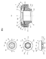
図1(A)、図1(B)および図1(C)は、本実施の形態に係る軸受装置1の平面図、底面図および正面図であり、図1(D)は、図1(A)に示す軸受装置1のA-A断面図である。
本実施の形態に係る軸受装置1は、軸回りの回転を許容しつつ、ストラット式サスペンション4(図4参照)に加わる荷重を支持するための装置であり、図示するように、スプリングシート2と、スプリングシート2上に載置された滑り軸受3と、を備えている。
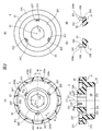
図2(A)および図2(B)は、スプリングシート2の平面図および底面図であり、図2(C)~(E)は、図2(A)に示すスプリングシート2のB-B断面図、C-C断面図、およびD-D断面図である。
スプリングシート2は、ガラス入りポリアミド樹脂等の強度の高い熱可塑性樹脂で形成され、図示するように、滑り軸受3を載置する環状の載置面200を含む上面20と、ストラット式サスペンション4のコイルスプリング42(図4参照)の上端部を支持する環状の支持面210を含む下面21と、下面21に形成され、ストラット式サスペンション4のバンプストッパ43(図4参照)の上端部を収容する筒状の収容部22と、を備えている。
載置面200の中央には、滑り軸受3の後述するロワーケース31を装着するための装着孔23が、下面21を貫き、収容部22と軸心Oを一致させて形成されている。
装着孔23の内周面230には、軸心Oに沿って、溝深さd1が一定のガイド溝231と、上面20側から下面21側に向かうに従い溝深さd2が浅くなるテーパ付ガイド溝232とが、円周方向に等間隔で交互に複数形成されている。ガイド溝231およびテーパ付ガイド溝232には、滑り軸受3の後述するロワーケース31の回止め314が挿入される。これにより、ロワーケース31がスプリングシート2の載置面200に対して回転するのを防止して、ロワーケース31およびスプリングシート2が両者間の摺動によって摩耗するのを防止することができる。また、テーパ付ガイド溝232に挿入された回止め314がテーパ付ガイド溝232に対してシメシロとなることにより、ロワーケース31がスプリングシート2に固定して、スプリングシート2および滑り軸受3間のガタつきによる異音の発生を防止することができる。なお、図2では、一部のガイド溝231、テーパ付ガイド溝232にのみ符号を付している。
収容部22の内周面221には、内方に突出する突起部222が周方向に等間隔で複数形成されている。突起部222は、収容部22に収容されたバンプストッパ43を径方向内方に押圧して固定する。また、個々の突起部222に対応して、上面20には、下面21まで貫通し、軸心Oに垂直な仮想平面において突起部222を枠内に収める窓孔207が形成されている。個々の突起部222に対応して窓孔207を設けたことにより、軸心O方向に相対移動する2つの金型(上型および下型)を用いて、スライド型なしで突起部222を形成することができる。
上面20の外縁側には、上面20を囲む環状突部201が形成されている。環状突部201には、環状突部201の内周面202および外周面203と連通して、環状突部201を分断し、上面20に溜まった液体を外部へ排水する複数の排水スリット204a、204bが、周方向に等間隔で交互に配置されている。なお、図2では、一部の排水スリット204a、204bにのみ符号を付している。
排水スリット204a、204bは、径方向と交差する方向P、Qに沿って形成された緩衝流路205a、205bを有する。これにより、車両の高圧洗浄等において、外部から径方向内方へ向かう高圧水が排水スリット204a、204bに侵入した場合でも、侵入した高圧水を緩衝流路205a、205bの壁面に衝突させて、浸入する水の勢いを弱めることができる。
ここで、排水スリット204a、204bの緩衝流路205a、205bは、互いの向きP、Qが異なっている。具体的には、両者の向きP、Qは交差している。このため、車両の高圧洗浄時において、外部から排水スリット204a、204bに侵入する高圧水の向きが緩衝流路205a、205bの向きP、Qのいずれか一方に近い場合、この高圧水の向きは他方とは交差する向きとなる。したがって、排水スリット204a、204bに侵入する水の向きに係らず、水の勢いを弱めることができる。
排水スリット204a、204bの底面206は、内縁側で上面20に連結しており、そこから径方向外方に向けて下面21側に傾斜している。このため、軸受装置1の軸心Oが鉛直となるように軸受装置1が車体に取り付けられる場合でも(図4参照)、上面20に溜まった液体を排水スリット204a、204bからより確実に排水できる。
図3(A)、図3(B)および図3(C)は、滑り軸受3の平面図、底面図および正面図であり、図3(D)は、図3(A)に示す滑り軸受3のE-E断面拡大図である。
図示するように、滑り軸受3は、環状のアッパーケース30と、ストラット式サスペンション4を構成するショックアブソーバ41のピストンロッド40が挿入されるとともに、アッパーケース30と回動自在に組み合わされる筒状のロワーケース31と、アッパーケース30とロワーケース31との間に配置された環状のセンタープレート32および金属ワッシャ33と、を備えている。
アッパーケース30は、ガラス入りポリアミド樹脂等の強度の高い熱可塑性樹脂で形成され、その上面300には、ストラット式サスペンション4を車体に取り付けるためのアッパーマウント5(図4参照)への取付面301が形成されている。また、アッパーケース30の下面302には、金属ワッシャ33を装着するための装着孔303が上面300を貫いて形成されており、下面302の装着孔303の周囲には、金属ワッシャ33の上面330と接触する環状下面304が形成されている。
ロワーケース31は、ストラット式サスペンション4を構成するショックアブソーバ41のピストンロッド40が挿入される。ロワーケース31は、必要に応じて潤滑油が含浸されたポリアセタール樹脂等の摺動特性に優れた熱可塑性樹脂で形成され、その上端面310には、センタープレート32が載置される環状上面311が形成されている。
ロワーケース31の外周面312には、滑り軸受3をスプリングシート2上に装着した場合に、スプリングシート2の上面20の載置面200と接触するフランジ部313が形成されている。また、外周面312には、滑り軸受3をスプリングシート2上に装着した場合に、スプリングシート2の装着孔23の内周面230に形成されたガイド溝231あるいはテーパ付ガイド溝232に挿入される回止め314が、円周方向に等間隔で複数形成されている。
センタープレート32は、ポリエチレン、熱可塑性ポリエステルエラストマ等の摺動特性に優れた樹脂で形成され、アッパーケース30の環状下面304とロワーケース31の環状上面311との間に配置される。これにより、アッパーケース30およびロワーケース31は、センタープレート32を介して相対的に回動する。
金属ワッシャ33は、アッパーケース30の環状下面304とセンタープレート32の上面320との間に配置され、ストラット式サスペンション4を構成するショックアブソーバ41のピストンロッド40が挿入される。金属ワッシャ33は、鋼、ステンレス等の鋼板、あるいは銅合金、チタン合金等の非鉄合金板で形成され、その上面330には、アッパーケース30の装着孔303に装着される筒状のボス部331が形成されている。
つぎに、本実施の形態に係る軸受装置1の適用例について説明する。
図4は、本実施の形態に係る軸受装置1が適用されたストラット式サスペンション4の概略断面図である。
図示するように、本実施の形態に係る軸受装置1は、例えば、ショックアブソーバ41と、ショックアブソーバ41を取り囲んで配されたコイルスプリング42と、を備えた自動車のストラット式サスペンション4に取り付けられる。この軸受装置1が取り付けられたストラット式サスペンション4は、アッパーマウント5を介して車体(不図示)に取り付けられる。
ショックアブソーバ41は、ピストンロッド40と、ピストンロッド40を取り囲むように配されたバンプストッパ43と、を備えている。
アッパーマウント5は、芯金51が埋設されたゴム等の弾性部材50で構成され、滑り軸受3のアッパーケース30の取付面301と接触するようにして、滑り軸受3を収容している。
スプリングシート2および滑り軸受3からなる軸受装置1は、アッパーマウント5とコイルスプリング42との間に配置され、ピストンロッド40が滑り軸受3に挿入された状態で、スプリングシート2の支持面210がコイルスプリング42の上端部を支持しつつ、スプリングシート2の収容部22がバンプストッパ43の上端部を収容する。
ピストンロッド40は、滑り軸受3のロワーケース31に挿入される大径部400と、大径部400に一体的に形成され、金属ワッシャ33に挿入される、大径部400より小径の小径部401と、小径部401に形成されたねじ部402と、を備えている。
ピストンロッド40の大径部400は、ロワーケース31の内周面315と、円周方向Rに回動自在に接触している。
ピストンロッド40の小径部401のねじ部402には、ナット6が螺合されている。ナット6は、ねじ部402に螺合してピストンロッド40に固定され、アッパーマウント5に対して円周方向Rに回転しないように、アッパーマウント5に収容されている。
滑り軸受3の金属ワッシャ33は、ピストンロッド40の大径部400と小径部401との間に形成される段差面403と、ねじ部402に螺合されたナット6との間に挟持されている。
滑り軸受3において、アッパーケース30は、ストラット式サスペンション4が滑り軸受3を介してアッパーマウント5に取り付けられることにより、ピストンロッド40の段差面403に固定された金属ワッシャ33によってアッパーマウント5に押し当てられる。これにより、アッパーケース30および金属ワッシャ33間の相対的な回転が阻止され、アッパーケース30は、ピストンロッド40に対して円周方向Rに回動しないようにアッパーマウント5に保持される。一方、ロワーケース31は、ロワーケース31およびスプリングシート2間の相対的な回転が阻止された状態でスプリングシート2に装着されており、スプリングシート2に従って円周方向Rに回動する。
上記構成のストラット式サスペンション4において、ステアリング操作によりコイルスプリング42が軸心O回りで円周方向Rに回転すると、コイルスプリング42を支持するスプリングシート2および滑り軸受3のロワーケース31も、コイルスプリング42とともに円周方向Rに回転する。一方、滑り軸受3の金属ワッシャ33およびアッパーケース30は、ピストンロッド40に対して円周方向Rに回動しないようにアッパーマウント5に保持されており、この結果、滑り軸受3において、金属ワッシャ33およびアッパーケース30とロワーケース31との間に、円周方向Rの相対的な回転が発生する。この相対的な回転は、ロワーケース31の環状上面311と金属ワッシャ33との間に配置されたセンタープレート32によりスムーズに行われ、これにより、ステアリング操作も抵抗なく行われる。
このように、軸受装置1は、滑り軸受3により、コイルスプリング42のアッパーマウント5に対する円周方向Rの回動を許容しつつ、スプリングシート2により、コイルスプリング42を介してストラット式サスペンション4に加わる車体の荷重を支持する。
以上、本発明の一実施の形態について説明した。
本実施の形態のスプリングシート2では、上面20の外縁側に、補強リブとして機能する環状突部201を形成し、この環状突部201に、上面20に溜まった液体を外部へ排水する複数の排水スリット204a、204bを設けている。スプリングシート2は、収容部22の内側にバンプストッパ43の上端部が収容され、収容部22の外側に、コイルスプリング42の上端部を支持する環状の支持面210を含む下面21が配される構造であるため、収容部22に大きな荷重が加わるが、補強リブとして機能する環状突部201に排水スリット204a、204bを設けているので、収容部22に排水用のオリフィスを設けることなく、上面20に溜まった液体を外部へ排水することができる。したがって、強度を維持しつつ、上面20に溜まった液体を排出することができる。
また、本実施の形態のスプリングシート2では、排水スリット204a、204bに、スプリングシート2の径方向と交差する方向P、Qに沿って形成された緩衝流路205a、205bを設けている。これにより、車両の高圧洗浄等において、外部から径方向内方へ向かう高圧水が排水スリット204a、204bに侵入した場合でも、侵入した高圧水を緩衝流路205a、205bの壁面に衝突させて、浸入する水の勢いを弱めることができる。
また、本実施の形態のスプリングシート2では、排水スリット204a、204bを周方向に交互に配置し、排水スリット204aの緩衝流路205aの向きPおよび排水スリット204bの緩衝流路205bの向きQを異ならせている。具体的には、両者の向きP、Qを交差させている。このため、車両の高圧洗浄時において、外部から排水スリット204a、204bに侵入する高圧水の向きが緩衝流路205a、205bの向きP、Qのいずれか一方に近い場合でも、この高圧水の向きが他方とは交差する向きとなるので、排水スリット204a、204bに侵入する水の向きに係らず、浸入する水の勢いを弱めることができる。
また、本実施の形態のスプリングシート2では、排水スリット204a、204bの底面206が内縁側で上面20に連結しており、そこから径方向外方に向けて下面21側に傾斜している。このため、軸受装置1の軸心Oが鉛直となるように軸受装置1が車体に取り付けられる場合でも(図4参照)、上面20に溜まった液体を排水スリット204a、204bからより確実に排水することができる。
また、本実施の形態のスプリングシート2では、収容部22の内周面221に設けられた突起部222により、収容部22に収容されたバンプストッパ43を固定するので、スプリングシート2の収容部22の内径を全周に亘りバンプストッパ43の外径に対してシメシロに設定する必要がない。このため、収容部22の内径を全周に亘りシメシロに設定した場合に比べて、バンプストッパ43の上端部をスプリングシート2の収容部22に挿入する際に要求される圧力を下げて抵抗を小さくすることができる。したがって、バンプストッパ43への装着作業の作業性を向上させることができる。
また、本実施の形態のスプリングシート2では、上面20に、個々の突起部222に対応して、下面21まで貫通し、軸心Oに垂直な仮想平面において突起部222を枠内に収める窓孔207を設けている。このため、軸心O方向に相対移動する2つの金型(上型および下型)を用いて、スライド型なしで突起部222を形成することができる。したがって、コストを増加させることなく、バンプストッパ43への装着作業の作業性を向上させることができる。
また、本実施の形態のスプリングシート2では、装着孔23の内周面230に、軸心Oに沿って、溝深さd1が一定のガイド溝231と、上面20側から下面21側に向かうに従い溝深さd2が浅くなるテーパ付ガイド溝232とを、円周方向に等間隔で交互に複数設け、これらのガイド溝231およびテーパ付ガイド溝232に、滑り軸受3のロワーケース31の回止め314を挿入している。これにより、ロワーケース31がスプリングシート2の載置面200に対して回転するのを防止して、ロワーケース31およびスプリングシート2が両者間の摺動によって摩耗するのを防止することができる。また、テーパ付ガイド溝232に挿入された回止め314がテーパ付ガイド溝232に対してシメシロとなることにより、ロワーケース31をスプリングシート2に固定して、スプリングシート2および滑り軸受3間のガタつきによる異音の発生を防止することができる。
また、本実施の形態のスプリングシート2では、特許文献1に記載のスプリングシートと異なり、環状の折り返し部を設けていないので、スプリングシート2の強度を向上させることができる。
なお、本発明は、上記の実施の形態に限定されるものではなく、その要旨の範囲内で数々の変形が可能である。
例えば、上記の実施の形態では、スプリングシート2の排水スリット204a、204bの底面206を、内縁側で上面20に連結させ、そこから径方向外方に向けて下面21側に傾斜させている。しかし、排水スリット204a、204bの底面206は、径方向外方に向けて下面21側に傾斜させなくてもよい。上面20と同一面上、あるいは上面20より下面21側に位置していればよい。また、上記の実施の形態において、上面20を、内側から径方向外方に向けて下面21側に傾斜させてもよい。この場合、例えば、排水スリット204a、204bの底面206を傾斜させた上面20と同一面上に形成する。
図4に示すストラット式サスペンション4において、軸心Oが鉛直方向に対して傾いている場合、スプリングシート2の上面20が水平方向に対して傾くので、排水スリット204a、204bの底面206が上面20と同一面上であっても、上面20に溜まった液体を排水スリット204a、204bから効率よく排水することができる。
また、上記の実施の形態では、スプリングシート2の径方向と交差する方向Pに沿って形成された緩衝流路205aを有する排水スリット204aと、スプリングシート2の径方向と交差し、かつ方向Pとは異なる方向Qに沿って形成された緩衝流路205bを有する排水スリット204bを、スプリングシート2の環状突部201に、周方向に交互に配置している。しかし、本発明はこれに限定されない。排水スリットは、環状突部201の内周面202および外周面203と連通して環状突部201を分断し、上面20に溜まった液体を外部へ排水することができるものであればよい。
図5(A)は、スプリングシート2の第一の変形例2Aの平面図である。
この変形例2Aが図2に示すスプリングシート2と異なる点は、排水スリット204a、204bに代えて、排水スリット204c、204dが、環状突部201に、周方向に等間隔で交互に配置されている点である。その他の構成は、図2に示すスプリングシート2と同様である。なお、図5(A)では、一部の排水スリット204c、204dにのみ符号を付している。
排水スリット204c、204dは、周方向に形成された緩衝流路205c、205dを有する。これにより、車両の高圧洗浄等において、外部から径方向内方へ向かう高圧水が排水スリット204c、204dに侵入した場合でも、侵入した高圧水を緩衝流路205c、205dの壁面に衝突させて、浸入する水の勢いを弱めることができる。
図5(B)は、スプリングシート2の第二の変形例2Bの平面図である。
この変形例2Bが図2に示すスプリングシート2と異なる点は、排水スリット204a、204bに代えて排水スリット204eが環状突部201に設けられている点である。その他の構成は、図2に示すスプリングシート2と同様である。
排水スリット204eは、周方向に形成された環状の緩衝流路205eと、周方向に複数配置され、環状突部201の外周面203および緩衝流路205eと連通する排水口208と、周方向に複数配置され、環状突部201の内周面202および緩衝流路205eと連通する流入口209と、を有する。なお、図5(B)では、一部の排水口208、流入口209にのみ符号を付している。
これにより、車両の高圧洗浄等において、外部から径方向内方へ向かう高圧水が排水口208に侵入した場合でも、侵入した高圧水を緩衝流路205eの壁面に衝突させて、浸入する水の勢いを弱めることができる。
図6(A)は、スプリングシート2の第三の変形例2Cの平面図である。
この変形例2Cが図2に示すスプリングシート2と異なる点は、排水スリット204a、204bに代えて、排水スリット204fが、環状突部201に、周方向に等間隔で配置されている点である。その他の構成は、図2に示すスプリングシート2と同様である。なお、図5(A)では、一部の排水スリット204fにのみ符号を付している。
排水スリット204fは、径方向と交差する方向Rに沿って形成された緩衝流路205fを有する。これにより、車両の高圧洗浄等において、外部から径方向内方へ向かう高圧水が排水スリット204fに侵入した場合でも、侵入した高圧水を緩衝流路205fの壁面に衝突させて、浸入する水の勢いを弱めることができる。
図6(B)は、スプリングシート2の第四の変形例2Dの平面図である。
この変形例2Dが図2に示すスプリングシート2と異なる点は、排水スリット204a、204bに代えて排水スリット204gが環状突部201に設けられている点である。その他の構成は、図2に示すスプリングシート2と同様である。
排水スリット204gは、周方向に形成された星型多角形状の緩衝流路205gと、周方向に複数配置され、環状突部201の外周面203および緩衝流路205gと連通する排水口208aと、周方向に複数配置され、環状突部201の内周面202および緩衝流路205gと連通する流入口209aと、を有する。緩衝流路205gは、周方向と交差する方向Sに沿って形成された緩衝流路205hと、周方向と交差し、かつ方向Rとは異なる方向Tに沿って形成された緩衝流路205iとが、交互に連結されて構成されている。また、排水口208aは、外縁側に位置する緩衝流路205hと緩衝流路205iとの連結部分に連通し、流入口209aは、内縁側に位置する緩衝流路205hと緩衝流路205iとの連結部分に連通している。なお、図6(B)では、一部の排水口208a、流入口209aにのみ符号を付している。
これにより、車両の高圧洗浄等において、外部から径方向内方へ向かう高圧水が排水口208aに侵入した場合でも、侵入した高圧水を緩衝流路205gの壁面に衝突させて、浸入する水の勢いを弱めることができる。また、外部から排水口208aに侵入する高圧水の向きが緩衝流路205h、205iの向きS、Tのいずれか一方に近い場合でも、この高圧水の向きが他方とは交差する向きとなるので、排水口208aに侵入する水の向きに係らず、浸入する水の勢いを弱めることができる。
また、上記の実施の形態では、スプリングシート2の環状突部201に排水スリットを設けた場合を例に取り説明したが、本発明はこれに限定されない。環状突部201の内周面202および外周面203と連通し、上面20に溜まった液体を外部へ排水する排水路を環状突部201に設けたものであればよい。例えば、環状突部201を貫通し、上面20に溜まった液体を外部へ排水する排水オリフィスを設けてもよい。
また、上記の実施の形態では、スプリングシート2の装着孔23の内周面230に、ガイド溝231およびテーパ付ガイド溝232を、円周方向に等間隔で交互に複数形成し、これに合わせて、滑り軸受3のロワーケース31の外周面312に、回止め314を円周方向に等間隔で複数形成しているが、本発明はこれに限定されない。ガイド溝231およびテーパ付ガイド溝232は、スプリングシート2の装着孔23の内周面230に、円周方向に並んで形成されていればよく、これに合わせて、回止め314も、滑り軸受3のロワーケース31の外周面312に、円周方向に並んで複数形成されていればよい。また、テーパ付ガイド溝232は省略されていてもよい。この場合でも、ロワーケース31がスプリングシート2の載置面200に対して回転するのを防止して、ロワーケース31およびスプリングシート2が両者間の摺動によって摩耗するのを防止することができる。
また、上記の実施の形態では、スプリングシート2の上面20に、個々の突起部222に対応して、下面21まで貫通し、軸心Oに垂直な仮想平面において突起部222を枠内に収める窓孔207を設けている。しかし、本発明はこれに限定されない。スライド型を用いて突起部222を形成する場合には、窓孔207を省略してもよい。この場合、スプリングシート2の強度をさらに向上させることができる。
また、上記の実施の形態では、滑り軸受3のロワーケース31とスプリングシート2とを別体としているが、これらを一体的に形成してもよい。
また、上記の実施の形態では、スプリングシート2の支持面210に直接、コイルスプリング42の上端部を接触させているが、スプリングシート2の下面21あるいはスプリングシート2の下面21および収容部22の外周面を覆うゴム、エラストマ等からなる緩衝材を設け、この緩衝材を介してスプリングシート2の支持面210にコイルスプリング42の上端部を接触させてもよい。この場合、緩衝材は、スプリングシート2と一体化されていても、別個でもよい。
また、上記の実施の形態では、スプリングシート2に組み合わせる軸受として、滑り軸受3を用いた場合を例にとり説明したが、本発明はこれに限定されない。軸受は、コイルスプリング42のアッパーマウント5に対する円周方向Rの回動を許容することができればよく、例えば転がり軸受でもよい。この場合、センタープレート32に代えて複数のボール、ローラ等の転がり部材が軸受部材として機能する。
また、本発明は、ストラット式サスペンションに限らず、ショックアブソーバおよびコイルスプリングを有するサスペンションに加わる荷重を支持する軸受装置に広く適用可能である。
1:軸受装置、 2:スプリングシート、 3:滑り軸受、 4:ストラット式サスペンション、 5:アッパーマウント、 6:ナット、 20:スプリングシート2の上面、 21:スプリングシート2の下面、 22:スプリングシート2の収容部、 23:スプリングシート2の、 30:アッパーケース、 31:ロワーケース、 32:センタープレート、 33:金属ワッシャ、 40:ピストンロッド、 41:ショックアブソーバ、 42:コイルスプリング、 43:バンプストッパ、 50:弾性部材、 51:芯金、 200:載置面、 201:環状突部、 202:環状突部201の内周面、 203:環状突部201の外周面、 204a~204g:排水スリット、 205a~205i:緩衝流路、 206:排水スリット204a、204bの底面、 207:窓孔、 208、208a:排水口、 209、209a:流入口、 210:スプリングシート2の支持面、 221:収容部22の内周面、 222:スプリングシート2の突起部、 230:装着孔23の内周面、 231:スプリングシート2のガイド溝、 232:スプリングシート2のテーパ付ガイド溝、 300:アッパーケース30の上面、 301:アッパーケース30の取付面、 302:アッパーケース30の下面、 303:アッパーケース30の装着孔、 304:アッパーケース30の環状下面、 310:ロワーケース31の上端面、 311:ロワーケース31の環状上面、 312:ロワーケース31の外周面、 313:ロワーケース31のフランジ部、 314:ロワーケース31の回止め、 315:ロワーケース31の内周面、 320:センタープレート32の上面、 330:金属ワッシャ33の上面、 331:金属ワッシャ33のボス部、 400:ピストンロッド40の大径部、 401:ピストンロッド40の小径部、 402:ピストンロッド40のねじ部、 403:ピストンロッド40の段差面
Claims (11)
- ショックアブソーバおよびコイルスプリングを有するサスペンションの前記コイルスプリングのバネ座として機能する合成樹脂製のスプリングシートであって、
前記サスペンションを車体に取り付けるためのアッパーマウント側に位置する上面と、
前記コイルスプリング側に位置する下面と、
前記下面に形成され、前記コイルスプリングの上端部を支持する支持部と、
前記上面の外縁側に形成され、当該上面を囲む環状の突部と、
前記突部の内周面および外周面と連通し、前記上面に溜まった液体を外部へ排水する排水路と、を備えている
ことを特徴とするスプリングシート。 - 請求項1に記載のスプリングシートであって、
前記排水路は、
径方向と交差する方向に沿って形成された緩衝流路を有する
ことを特徴とするスプリングシート。 - 請求項1または2に記載のスプリングシートであって、
前記排水路は、
周方向に複数形成されている
ことを特徴とするスプリングシート。 - 請求項3に記載のスプリングシートであって、
周方向に複数形成された前記排水路は、
周方向に隣り合うもの同士の向きが異なる
ことを特徴とするスプリングシート。 - 請求項1ないし4のいずれか一項に記載のスプリングシートであって、
前記排水路は、
当該排水路の底面が前記上面と同一面上、あるいは前記上面より前記下面側に位置している
ことを特徴とするスプリングシート。 - 請求項1ないし5のいずれか一項に記載のスプリングシートであって、
前記排水路は、
当該排水路の底面が径方向内方から径方向外方に向けて前記下面側に傾斜している
ことを特徴とするスプリングシート。 - 請求項1ないし6のいずれか一項に記載のスプリングシートであって、
前記上面は、
径方向内方から径方向外方に向けて前記下面側に傾斜している
ことを特徴とするスプリングシート。 - 請求項1ないし7のいずれか一項に記載にスプリングシートであって、
前記排水路は、
前記突部を分断するスリット状に形成されている
ことを特徴とするスプリングシート。 - 請求項1ないし7のいずれか一項に記載にスプリングシートであって、
前記排水路は、
前記突部を貫通するオリフィス状に形成されている
ことを特徴とするスプリングシート。 - ショックアブソーバおよびコイルスプリングを有するサスペンションに加わる荷重を支持する軸受装置であって、
請求項1ないし9のいずれか一項に記載のスプリングシートと、
前記サスペンションを車体に取り付けるためのアッパーマウントと前記スプリングシートとの間に配され、前記スプリングシートの前記アッパーマウントに対する相対的な回動を許容する軸受と、を備えている
ことを特徴とする軸受装置。 - 請求項10に記載の軸受装置であって、
前記軸受は、
前記アッパーマウント側に位置するアッパーケースと、
前記コイルスプリング側に位置するロワーケースと、
前記アッパーケースおよび前記ロワーケース間に配されて、前記アッパーケースおよび前記ロワーケース間の相対的な回動を許容する軸受部材と、を備え、
前記ロワーケースは、
前記スプリングシートと一体化されている
ことを特徴とする軸受装置。
Applications Claiming Priority (2)
| Application Number | Priority Date | Filing Date | Title |
|---|---|---|---|
| JP2017-140164 | 2017-07-19 | ||
| JP2017140164A JP6764836B2 (ja) | 2017-07-19 | 2017-07-19 | スプリングシートおよび軸受装置 |
Publications (1)
| Publication Number | Publication Date |
|---|---|
| WO2019017232A1 true WO2019017232A1 (ja) | 2019-01-24 |
Family
ID=65015940
Family Applications (1)
| Application Number | Title | Priority Date | Filing Date |
|---|---|---|---|
| PCT/JP2018/025942 Ceased WO2019017232A1 (ja) | 2017-07-19 | 2018-07-09 | スプリングシートおよび軸受装置 |
Country Status (2)
| Country | Link |
|---|---|
| JP (1) | JP6764836B2 (ja) |
| WO (1) | WO2019017232A1 (ja) |
Families Citing this family (1)
| Publication number | Priority date | Publication date | Assignee | Title |
|---|---|---|---|---|
| DE102018204485A1 (de) * | 2017-07-07 | 2019-01-10 | Continental Teves Ag & Co. Ohg | Luftfederbein mit abgedichtetem Verschlussdeckel |
Citations (5)
| Publication number | Priority date | Publication date | Assignee | Title |
|---|---|---|---|---|
| JPH11129721A (ja) * | 1997-10-31 | 1999-05-18 | Chuo Spring Co Ltd | 車両懸架装置 |
| JP2004263773A (ja) * | 2003-02-28 | 2004-09-24 | Oiles Ind Co Ltd | スラスト滑り軸受を用いたストラット型サスペンションの取付構造及びそのスラスト滑り軸受 |
| US20080174060A1 (en) * | 2001-07-25 | 2008-07-24 | Richard Pare | Hydraulic load centering spring perch |
| JP2008232304A (ja) * | 2007-03-20 | 2008-10-02 | Oiles Ind Co Ltd | スラスト滑り軸受並びにこのスラスト滑り軸受とピストンロッド及びコイルばねとの組合せ機構 |
| JP2016053409A (ja) * | 2014-09-04 | 2016-04-14 | 株式会社ショーワ | スプリングシート |
-
2017
- 2017-07-19 JP JP2017140164A patent/JP6764836B2/ja active Active
-
2018
- 2018-07-09 WO PCT/JP2018/025942 patent/WO2019017232A1/ja not_active Ceased
Patent Citations (5)
| Publication number | Priority date | Publication date | Assignee | Title |
|---|---|---|---|---|
| JPH11129721A (ja) * | 1997-10-31 | 1999-05-18 | Chuo Spring Co Ltd | 車両懸架装置 |
| US20080174060A1 (en) * | 2001-07-25 | 2008-07-24 | Richard Pare | Hydraulic load centering spring perch |
| JP2004263773A (ja) * | 2003-02-28 | 2004-09-24 | Oiles Ind Co Ltd | スラスト滑り軸受を用いたストラット型サスペンションの取付構造及びそのスラスト滑り軸受 |
| JP2008232304A (ja) * | 2007-03-20 | 2008-10-02 | Oiles Ind Co Ltd | スラスト滑り軸受並びにこのスラスト滑り軸受とピストンロッド及びコイルばねとの組合せ機構 |
| JP2016053409A (ja) * | 2014-09-04 | 2016-04-14 | 株式会社ショーワ | スプリングシート |
Also Published As
| Publication number | Publication date |
|---|---|
| JP2019018750A (ja) | 2019-02-07 |
| JP6764836B2 (ja) | 2020-10-07 |
Similar Documents
| Publication | Publication Date | Title |
|---|---|---|
| EP3527836B1 (en) | Synthetic resin slide bearing | |
| EP3002137B1 (en) | Suspension bearing device, motor vehicle equipped with such a suspension bearing device and manufacturing method | |
| US20180051769A1 (en) | Nozzle plate of engine mount | |
| EP3002136A1 (en) | Suspension bearing device, motor vehicle equipped with such a suspension bearing device and manufacturing method | |
| CN107532642B (zh) | 滑动轴承 | |
| US9421819B2 (en) | Vehicle wheel hubcap with vent | |
| US10180160B2 (en) | Hub unit | |
| US20030151178A1 (en) | Hydraulically damping bush bearing | |
| JP5948233B2 (ja) | サスペンション用アッパ部材 | |
| CN111483283B (zh) | 悬架推力轴承装置以及配备有这种装置的悬架支柱 | |
| CN111483282B (zh) | 悬架推力轴承装置以及配备有这种装置的悬架支柱 | |
| JP6764836B2 (ja) | スプリングシートおよび軸受装置 | |
| JP6807284B2 (ja) | 軸受装置 | |
| JP4325198B2 (ja) | 合成樹脂製の滑り軸受及びこの滑り軸受を用いたストラット型サスペンションの取付構造 | |
| EP1787890A1 (en) | Steering unit | |
| US7243766B2 (en) | Rebound cushion for hydraulic shock absorber | |
| JP2019152315A (ja) | スプリングシートおよびサスペンション取付構造 | |
| DE19527260A1 (de) | Hydraulisch dämpfendes Motorlager | |
| WO2019013132A1 (ja) | スプリングシートおよび軸受装置 | |
| EP2660487B1 (en) | Bearing sump with bi-directional stiffness | |
| WO2019013076A1 (ja) | スプリングシートおよび軸受装置 | |
| JP2019018750A5 (ja) | ||
| KR20180026338A (ko) | 허브 유닛 | |
| JP6822860B2 (ja) | 防振装置 | |
| JP2016041949A (ja) | 車輪支持用転がり軸受ユニット |
Legal Events
| Date | Code | Title | Description |
|---|---|---|---|
| 121 | Ep: the epo has been informed by wipo that ep was designated in this application |
Ref document number: 18835501 Country of ref document: EP Kind code of ref document: A1 |
|
| NENP | Non-entry into the national phase |
Ref country code: DE |
|
| 122 | Ep: pct application non-entry in european phase |
Ref document number: 18835501 Country of ref document: EP Kind code of ref document: A1 |