WO2019017004A1 - 触媒担体及び排気浄化装置 - Google Patents
触媒担体及び排気浄化装置 Download PDFInfo
- Publication number
- WO2019017004A1 WO2019017004A1 PCT/JP2018/010809 JP2018010809W WO2019017004A1 WO 2019017004 A1 WO2019017004 A1 WO 2019017004A1 JP 2018010809 W JP2018010809 W JP 2018010809W WO 2019017004 A1 WO2019017004 A1 WO 2019017004A1
- Authority
- WO
- WIPO (PCT)
- Prior art keywords
- catalyst
- carrying
- outer cylinder
- filters
- axial direction
- Prior art date
Links
- 239000003054 catalyst Substances 0.000 title claims abstract description 196
- 238000000746 purification Methods 0.000 title claims abstract description 55
- 238000010030 laminating Methods 0.000 claims abstract description 7
- 238000005245 sintering Methods 0.000 claims abstract description 3
- 238000002485 combustion reaction Methods 0.000 claims description 42
- 230000002093 peripheral effect Effects 0.000 claims description 37
- 229910052751 metal Inorganic materials 0.000 claims description 28
- 239000002184 metal Substances 0.000 claims description 28
- 239000000463 material Substances 0.000 claims description 17
- 238000011144 upstream manufacturing Methods 0.000 claims description 11
- 239000000969 carrier Substances 0.000 claims description 6
- 239000000126 substance Substances 0.000 abstract description 34
- 239000007789 gas Substances 0.000 description 60
- 239000012530 fluid Substances 0.000 description 20
- 230000000694 effects Effects 0.000 description 16
- 238000003466 welding Methods 0.000 description 15
- MWUXSHHQAYIFBG-UHFFFAOYSA-N nitrogen oxide Inorganic materials O=[N] MWUXSHHQAYIFBG-UHFFFAOYSA-N 0.000 description 13
- 230000000875 corresponding effect Effects 0.000 description 12
- 238000009434 installation Methods 0.000 description 10
- 230000007423 decrease Effects 0.000 description 8
- 230000004048 modification Effects 0.000 description 7
- 238000012986 modification Methods 0.000 description 7
- 239000011324 bead Substances 0.000 description 5
- 238000006555 catalytic reaction Methods 0.000 description 5
- 230000036961 partial effect Effects 0.000 description 5
- UGFAIRIUMAVXCW-UHFFFAOYSA-N Carbon monoxide Chemical compound [O+]#[C-] UGFAIRIUMAVXCW-UHFFFAOYSA-N 0.000 description 4
- 229910002091 carbon monoxide Inorganic materials 0.000 description 4
- 229930195733 hydrocarbon Natural products 0.000 description 4
- 150000002430 hydrocarbons Chemical class 0.000 description 4
- 230000035515 penetration Effects 0.000 description 4
- 229910001220 stainless steel Inorganic materials 0.000 description 3
- 239000010935 stainless steel Substances 0.000 description 3
- 230000003197 catalytic effect Effects 0.000 description 2
- 230000003247 decreasing effect Effects 0.000 description 2
- 230000003252 repetitive effect Effects 0.000 description 2
- 230000003584 silencer Effects 0.000 description 2
- 230000001629 suppression Effects 0.000 description 2
- PNEYBMLMFCGWSK-UHFFFAOYSA-N aluminium oxide Inorganic materials [O-2].[O-2].[O-2].[Al+3].[Al+3] PNEYBMLMFCGWSK-UHFFFAOYSA-N 0.000 description 1
- 238000006243 chemical reaction Methods 0.000 description 1
- 238000005520 cutting process Methods 0.000 description 1
- 238000006073 displacement reaction Methods 0.000 description 1
- 238000005304 joining Methods 0.000 description 1
- 238000003475 lamination Methods 0.000 description 1
- 230000014759 maintenance of location Effects 0.000 description 1
- 230000000737 periodic effect Effects 0.000 description 1
- 230000001737 promoting effect Effects 0.000 description 1
- 238000000926 separation method Methods 0.000 description 1
- 230000001743 silencing effect Effects 0.000 description 1
- 230000000087 stabilizing effect Effects 0.000 description 1
- XLYOFNOQVPJJNP-UHFFFAOYSA-N water Substances O XLYOFNOQVPJJNP-UHFFFAOYSA-N 0.000 description 1
Images


Classifications
-
- B—PERFORMING OPERATIONS; TRANSPORTING
- B01—PHYSICAL OR CHEMICAL PROCESSES OR APPARATUS IN GENERAL
- B01D—SEPARATION
- B01D53/00—Separation of gases or vapours; Recovering vapours of volatile solvents from gases; Chemical or biological purification of waste gases, e.g. engine exhaust gases, smoke, fumes, flue gases, aerosols
- B01D53/34—Chemical or biological purification of waste gases
- B01D53/92—Chemical or biological purification of waste gases of engine exhaust gases
- B01D53/94—Chemical or biological purification of waste gases of engine exhaust gases by catalytic processes
-
- B—PERFORMING OPERATIONS; TRANSPORTING
- B01—PHYSICAL OR CHEMICAL PROCESSES OR APPARATUS IN GENERAL
- B01J—CHEMICAL OR PHYSICAL PROCESSES, e.g. CATALYSIS OR COLLOID CHEMISTRY; THEIR RELEVANT APPARATUS
- B01J35/00—Catalysts, in general, characterised by their form or physical properties
- B01J35/50—Catalysts, in general, characterised by their form or physical properties characterised by their shape or configuration
- B01J35/56—Foraminous structures having flow-through passages or channels, e.g. grids or three-dimensional monoliths
-
- F—MECHANICAL ENGINEERING; LIGHTING; HEATING; WEAPONS; BLASTING
- F01—MACHINES OR ENGINES IN GENERAL; ENGINE PLANTS IN GENERAL; STEAM ENGINES
- F01N—GAS-FLOW SILENCERS OR EXHAUST APPARATUS FOR MACHINES OR ENGINES IN GENERAL; GAS-FLOW SILENCERS OR EXHAUST APPARATUS FOR INTERNAL COMBUSTION ENGINES
- F01N3/00—Exhaust or silencing apparatus having means for purifying, rendering innocuous, or otherwise treating exhaust
- F01N3/02—Exhaust or silencing apparatus having means for purifying, rendering innocuous, or otherwise treating exhaust for cooling, or for removing solid constituents of, exhaust
- F01N3/021—Exhaust or silencing apparatus having means for purifying, rendering innocuous, or otherwise treating exhaust for cooling, or for removing solid constituents of, exhaust by means of filters
- F01N3/033—Exhaust or silencing apparatus having means for purifying, rendering innocuous, or otherwise treating exhaust for cooling, or for removing solid constituents of, exhaust by means of filters in combination with other devices
- F01N3/035—Exhaust or silencing apparatus having means for purifying, rendering innocuous, or otherwise treating exhaust for cooling, or for removing solid constituents of, exhaust by means of filters in combination with other devices with catalytic reactors, e.g. catalysed diesel particulate filters
-
- F—MECHANICAL ENGINEERING; LIGHTING; HEATING; WEAPONS; BLASTING
- F01—MACHINES OR ENGINES IN GENERAL; ENGINE PLANTS IN GENERAL; STEAM ENGINES
- F01N—GAS-FLOW SILENCERS OR EXHAUST APPARATUS FOR MACHINES OR ENGINES IN GENERAL; GAS-FLOW SILENCERS OR EXHAUST APPARATUS FOR INTERNAL COMBUSTION ENGINES
- F01N3/00—Exhaust or silencing apparatus having means for purifying, rendering innocuous, or otherwise treating exhaust
- F01N3/08—Exhaust or silencing apparatus having means for purifying, rendering innocuous, or otherwise treating exhaust for rendering innocuous
- F01N3/10—Exhaust or silencing apparatus having means for purifying, rendering innocuous, or otherwise treating exhaust for rendering innocuous by thermal or catalytic conversion of noxious components of exhaust
- F01N3/24—Exhaust or silencing apparatus having means for purifying, rendering innocuous, or otherwise treating exhaust for rendering innocuous by thermal or catalytic conversion of noxious components of exhaust characterised by constructional aspects of converting apparatus
Definitions
- the present invention relates to purification treatment of exhaust gas generated in an internal combustion engine of a four-wheeled vehicle or a two-wheeled motor vehicle, and relates to a catalyst carrier and an exhaust gas purification device for removing harmful substances in the exhaust gas by catalytic reaction.
- Patent Document 1 discloses a strip-shaped metal sheet of ferritic heat-resistant stainless steel and metal A corrugated plate is overlapped and wound spirally to form a cylindrical honeycomb structure, a catalyst material is supported on the surface of the honeycomb structure, and the honeycomb structure supporting the catalyst material is inserted into a cylindrical outer cylinder.
- a catalyst carrier is disclosed in which the outer edges on both sides of this honeycomb structure are fixed by laser welding to the outer cylinder.
- the catalyst support In the catalyst carrier using this honeycomb structure, in order to obtain the catalytic reaction necessary for sufficient removal of harmful substances, it is necessary to lengthen the linear flow path through which the exhaust gas of the honeycomb structure supporting the catalyst material flows. Therefore, the catalyst support has a large linear thickness and size, which considerably restricts the installation location in the exhaust path.
- the metal mesh laminated porous body is a porous body obtained by laminating and sintering a plurality of metal mesh, and for example, an alumina thin layer on which a catalyst material is dispersed and supported is formed on the surface thereof to be a catalyst-carrying filter.
- the flow path through which the exhaust gas passes is curved in three dimensions to enhance the contact between the exhaust gas and the catalyst substance, and is thicker than the honeycomb structure carrying the catalyst substance. Can be made much thinner.
- the catalyst-carrying filter in Patent Document 2 when the catalyst-carrying filter in Patent Document 2 is incorporated in the outer cylinder to make a catalyst carrier, the catalyst having excellent purification performance to some extent by arranging a plurality of catalyst-carrying filters in the axial direction of the outer cylinder and incorporating in the outer cylinder. It is possible to obtain a carrier.
- a carrier for example, when a plurality of catalyst-carrying filters having the same shape and the same opening site are arranged in the axial direction with the positions of the opening sites aligned in the axial direction, the openings communicating in the axial direction of the plurality of catalyst-carrying filters There is a high probability that the exhaust will pass through the area in a short time without air flow collisions. Therefore, sufficient contact of the exhaust gas with the catalyst substance can not be obtained, and there is a possibility that the catalyst carrier can not exhibit sufficient purification performance.
- the present invention is proposed in view of the above problems, and in a catalyst carrier in which a plurality of catalyst-carrying filters having a catalyst material supported on a metal mesh laminated porous body are incorporated in an outer cylinder, the contact between the catalyst material and exhaust gas is enhanced. It is an object of the present invention to provide a catalyst carrier capable of performing the exhaust gas purification process more reliably, and an exhaust gas purification apparatus provided with the catalyst carrier.
- the catalyst support of the present invention is composed of a porous metal mesh laminated porous body in which a plurality of metal nets are laminated and sintered, and a catalyst supporting filter for dispersing and supporting a catalyst substance, and a plurality of the aforementioned catalyst supporting filters are aligned in the axial direction
- the plurality of catalyst-carrying filters are disposed such that the plurality of catalyst-carrying filters are provided such that the opening area is smaller than the opening area of one catalyst-carrying filter as viewed in the axial direction.
- the exhaust gas is bypassed in a short time without collision of the air flow. It is possible to reduce the possibility of the reaction and to improve the contact between the catalyst substance and the circulating exhaust gas. Therefore, the excellent purification performance of the catalyst carrier in which the plurality of catalyst-carrying filters in which the catalyst material is supported on the metal mesh laminated porous body is incorporated in the outer cylinder can be more reliably exhibited. In addition, since the exhaust gas easily collides with the catalyst-carrying filter, kinetic energy of the exhaust gas can be reduced to obtain the muffling effect of the exhaust gas.
- a catalyst carrier in which a plurality of metal nets are stacked and sintered, and a plurality of catalyst-carrying filters carrying a catalyst material dispersedly supported is arranged in parallel in the axial direction is longer than the catalyst carrier of the existing honeycomb structure. It is possible to shorten the length and to increase the degree of freedom and flexibility of the installation location in the exhaust path.
- the catalyst carrier according to the present invention is characterized in that the opening area of the plurality of catalyst loaded filters in the axial direction of the outer cylinder is 0% or more and 20.9% or less with respect to the inner cross sectional area of the outer cylinder. I assume. According to this, it is possible to further reduce the possibility of exhaust gas passing in a short time without collision of the air flow, and to further improve the contact between the catalyst substance and the circulating exhaust gas and the purification performance. In addition, since the exhaust gas easily collides with the catalyst-carrying filter, the muffling effect due to the reduction of kinetic energy of the exhaust gas can be further enhanced. Further, since the convergence tendency of the pressure loss becomes remarkable, it is possible to enhance the effect of suppressing the variation in the performance of the engine output, the noise reduction and the purification.
- the catalyst carrier according to the present invention is characterized in that the opening area of the plurality of catalyst loaded filters in the axial direction view of the outer cylinder is 0% or more and 10% or less with respect to the inner cross sectional area of the outer cylinder. More preferably, it is 0% or more and 5.1% or less. According to this, the contact property between the catalyst substance and the circulating exhaust, the purification performance, and the muffling effect can be further enhanced, and the variation suppressing effect on the engine output, the muffling, and the purification performance can be more reliably obtained.
- the catalyst carrier according to the present invention is characterized in that the plurality of catalyst supporting filters are disposed such that the opening area of the plurality of catalyst supporting filters in the axial direction view of the outer cylinder is zero.
- basically all of the exhaust flow flowing through the outer cylinder can be made to collide with the structure constituted by the plurality of catalyst-carrying filters, and the exhaust flow with respect to the plurality of catalyst-carrying filter structures It is possible to further increase the retention time of the catalyst and to further improve the contact of the circulating exhaust with the catalyst substance and the purification performance. In addition, it is possible to prevent the occurrence of a region having low contact with the catalytic substance locally and having a low degree of purification in the exhaust gas flow.
- the engine output performance of the internal combustion engine tends to increase as the opening area increases, and the opening area increases.
- the exhaust purification performance and the noise reduction performance, which tend to decrease, can be stabilized and set easily, and variations in engine output, noise reduction, and purification performance can be minimized.
- the exhaust gas easily collides with the catalyst-carrying filter, the muffling effect due to the reduction of kinetic energy of the exhaust gas can be further enhanced.
- the catalyst carrier of the present invention is characterized in that the openings of the plurality of the catalyst-carrying filters in the axial direction of the outer cylinder are dispersedly arranged. According to this, by disposing the openings of the plurality of catalyst-carrying filters in the axial direction of the outer cylinder in a dispersed manner, the contact with the catalyst substance locally in the exhaust flow is low and the region with a low degree of purification Can be prevented.
- the catalyst carrier according to the present invention is characterized in that the plurality of the catalyst-carrying filters are axially arranged in proximity to or adjacent to each other. According to this, by arranging a plurality of catalyst-carrying filters in an axial direction in the vicinity or adjacent to each other, the length of the catalyst carrier can be made shorter, and the degree of freedom of the installation place in the exhaust route and the flexibility Sex can be further enhanced.
- the exhaust flow can be kept within the necessary range while the exhaust flow stays in the structure composed of a plurality of catalyst-carrying filters within a necessary range, and the rise in exhaust pressure can be suppressed, thereby suppressing the exhaust pressure. It can be made easy to adjust and adapt when it is required to prevent the engine output from decreasing.
- the catalyst carrier of the present invention is characterized in that at least one of the plurality of catalyst-carrying filters of the plurality of catalyst-carrying filters is arranged in the axial direction at a distance from the other catalyst-carrying filters. According to this, the spacing between the catalyst-carrying filters can also be utilized to promote the turbulent flow of the exhaust flow, and the turbulent flow of the exhaust further enhances the contact between the catalyst substance and the circulating exhaust, thereby improving the purification performance. It can be further improved.
- the outer cylinder is made of metal, and the outer peripheral end of each of the catalyst-carrying filters is formed so as to substantially abut the inner peripheral surface of the outer cylinder, and the thickness direction of the catalyst-carrying filter
- the end face of the wire positioned at the outer peripheral end of the catalyst-carrying filter is welded to the inner peripheral surface of the outer cylinder which contacts.
- a welded portion welded to the inner peripheral surface of the outer cylinder with which the end face of the wire located at the outer peripheral end of the catalyst-carrying filter abuts may be provided over the entire periphery.
- the catalyst-carrying filter by welding in the middle region of the catalyst-carrying filter, burn-through and thermal deformation due to welding of the catalyst-carrying filter or the metal mesh-laminated porous body in which a plurality of wire nets are stacked and sintered are prevented.
- It can be a catalyst carrier in which the shape of the supported filter is maintained.
- the outer peripheral end of the catalyst-carrying filter in which the end faces of the wires are randomly arranged can be welded to the inner peripheral surface of the outer cylinder with high strength, and mounted on the exhaust purification system In addition, heat, vibration, exhaust pressure, etc. can provide sufficient strength that does not break.
- the outer end of the catalyst-carrying filter in which the end face of the wire is randomly disposed The welding can be performed with high strength by the inner peripheral surface of the outer cylinder.
- the exhaust gas purification apparatus of the present invention is characterized in that the catalyst carrier of the present invention is provided at a plurality of spaced locations in the exhaust gas path of an internal combustion engine. According to this, it is possible to obtain an exhaust gas purification device having the effect of the catalyst carrier of the present invention, and, for example, types of harmful substances such as carbon monoxide (CO), hydrocarbons (HC), nitrogen oxides (NOx) It is also possible to adjust the catalyst substance of each catalyst carrier according to the situation, install each catalyst carrier in a place where each harmful substance is more likely to cause a catalytic reaction, and enhance the overall purification performance.
- CO carbon monoxide
- HC hydrocarbons
- NOx nitrogen oxides
- the exhaust gas purification apparatus of the present invention is characterized in that one of the catalyst carriers of the present invention is provided at the upstream position of the exhaust gas path of the internal combustion engine.
- the upstream position of the internal combustion engine includes the case where the distance between the internal combustion engine and the end portion on the internal combustion engine side of the catalyst-carrying filter closest to the internal combustion engine on the catalyst carrier is 0 to 300 mm.
- the catalyst support of the present invention can be made compact in both axial dimension and cross-sectional area, and can be installed at a desired location of the exhaust path, by arranging the catalyst support at the upstream position of the internal combustion engine
- the contact of the exhaust gas with the catalyst substance can be enhanced with almost no loss of exhaust energy, and the exhaust gas performance can be dramatically improved.
- the exhaust gas control apparatus of the present invention is characterized in that the catalyst carrier is provided at an upstream position of an exhaust pipe which is piped from an outlet of an internal combustion engine of a motorcycle.
- the exhaust pipe piped from the outlet of the internal combustion engine has a complicated layout in which a small diameter and a plurality of bends are added to avoid interference with other parts.
- the exhaust gas purification device using the catalyst carrier according to the present invention is an exhaust system of a motorcycle having such dimensional limitations due to its compactness. It is also possible to install a pipe.
- the contact between the catalyst material and the exhaust can be enhanced, and the purification is excellent. Performance can be reliably exhibited.
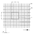
- FIG. 2 is an enlarged explanatory view of a portion B in FIG.
- A) is a partial longitudinal cross-sectional explanatory view of the metal mesh which comprises the catalyst support filter of the catalyst support of 1st Embodiment
- B) is a partial longitudinal cross-section explanatory view of the catalyst support filter of the catalyst support of 1st Embodiment.
- (A) is a side view of a catalyst-carrying filter of a catalyst carrier according to the first embodiment
- (b) is an enlarged view of part C
- (c) is an explanatory view for explaining a welding state in part C.
- (A) is a front view of the catalyst carrier of 3rd Embodiment by this invention
- (b) is the longitudinal cross-section explanatory drawing.
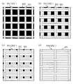
- (A)-(d) is a front view which shows the example of the catalyst support filter which comprises an analysis model.
- (A)-(d) is a front view which shows the example of the state which each rotated the catalyst support filter which comprises an analysis model 90 degree
- (A)-(d) is a front view which shows the example of the structure which accumulated and set two catalyst carrying
- (A) is explanatory drawing which shows the analysis model by the structure which adjacently arranged the catalyst support filter
- (b) is explanatory drawing which shows the analysis model by the structural unit which spaced apart the catalyst support filter.
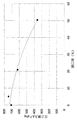
- the graph which shows the relationship between the opening ratio and the pressure loss in the structure which adjacently arranges the catalyst loading filter.
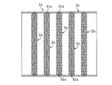
- the catalyst carrier 1 includes a catalyst-carrying filter 2 on which a catalyst material is dispersed and supported, and a metal outer cylinder 3 on which the catalyst-carrying filter 2 is embedded.
- the catalyst-carrying filter 2 is composed of a multi-layered wire mesh laminated porous body in which a plurality of wire nets 20 are laminated and sintered, and in the illustrated example, five wire nets 20 are laminated and sintered in five layers.
- the metal mesh laminated porous body is formed, and the catalyst material is dispersed and supported on the metal mesh laminated porous body. Then, a plurality of catalyst-carrying filters 2 are arranged in the axial direction and installed in the outer cylinder 3.
- each catalyst-carrying filter 2 is formed so as to substantially abut the inner peripheral surface 31 of the outer cylinder 3.
- the outer cylinder 3 in the illustrated example is formed of a metal such as stainless steel in a substantially cylindrical short cylinder shape, and its plate thickness is t2.
- the outer diameter of the outer peripheral end of the substantially circular catalyst-carrying filter 2 is formed to be substantially the same as the inner diameter of the outer cylinder 3 so as to substantially abut the inner peripheral surface 31 of the outer cylinder 3.
- the substantially circular catalyst-carrying filter 2 formed of a substantially circular wire mesh 20 formed by cutting the wire mesh 20 a into a circular shape, the end face 21 of the wire which is a cut surface is exposed at the outer peripheral end, The end face 21 of the wire is substantially in contact with the inner circumferential surface 31 of the outer cylinder 3.
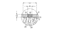
- Each catalyst-carrying filter 2 is, as shown in FIG. 4, an outer cylinder 3 with which the end face 21 of the wire located at the outer peripheral end of the catalyst-carrying filter 2 abuts in an intermediate region 45 which revolves in the middle in the thickness direction.
- the welding portion 42 is welded to the inner circumferential surface 31 of the second embodiment.
- a welded portion 42 welded to the inner peripheral surface 31 of the outer cylinder 3 in contact with the end surface 21 of the wire positioned at the outer peripheral end of the catalyst-carrying filter 2 is provided over the entire periphery in the intermediate region 45
- the end face 21 of the wire contacting the inner peripheral surface 31 of the outer cylinder 3 is randomly attached to the inner peripheral surface 31 of the outer cylinder 3 at the weld 42 at a portion exposed at the outer peripheral end and located in the intermediate region 45. It is welded.
- a portion welded to the inner peripheral surface 31 of the outer cylinder 3 to which the portion of the wire mesh 20 other than the end face 21 of the wire abut may co-exist with the welded portion 42 of the end face 21 of the wire. .
- the intermediate region 45 substantially corresponds to the wave height h and the position and width of one layer of the wire mesh 20 which is an intermediate layer in the wire mesh layer formed by laminating a plurality of three or more wire meshes 20 of the catalyst-carrying filter 2.
- the middle region 45 in the illustrated example substantially corresponds to the wave height h, the position, and the width of the third-layer wire mesh 20 located at the center among the wire mesh layers in which the wire mesh 20 is laminated in five layers.
- the width W of the intermediate region 45 is set to be substantially the same as the wave height h of the wire mesh 20.
- 41 in FIGS. 1 and 2 is a weld bead, and when welding the end surface 21 of the wire of the catalyst-carrying filter 2 or a part of the end surface 21 to the inner peripheral surface 31 of the outer cylinder 3 at the welding portion 42 It is formed when laser penetration welding is applied from the outside of the outer cylinder 3.
- the width of the inner peripheral surface 31 of the outer cylinder 3 of the weld bead 41 substantially corresponds to the width W of the intermediate region 45, and the welding width of the inner peripheral surface 31 of the outer cylinder 3 is the width W of the intermediate region 45 Laser penetration welding is applied.
- the plurality of catalyst-carrying filters 2 installed in the outer cylinder 3 are provided adjacent to or adjacent to each other in the axial direction of the outer cylinder 3.
- a total of five catalyst-carrying filters 2 are internally disposed at a substantially intermediate position in the longitudinal direction of the outer cylinder 3, and each catalyst-carrying filter 2 is continuous in proximity or adjacent to each other. It is provided in parallel inside the outer cylinder 3, and is provided so as to extend over the entire inner empty cross section of the outer cylinder 3.
- the plurality of catalyst-carrying filters 2 are disposed such that the opening area in the axial direction of the outer cylinder 3 is smaller than the opening area of the outer cylinder 3 of the single catalyst-carrying filter 2 in the axial direction. In one embodiment, the plurality of catalyst loading filters 2 are installed such that the opening areas of the plurality of catalyst loading filters 2 in the axial direction of the outer cylinder 3 become zero.
- the shielding part 5 is comprised in FIG.
- the opening area of the plurality of catalyst loading filters 2 in the axial direction of the outer cylinder 3 is 0 by the shielding portion 5, and linear light is emitted when visible light is applied to the inside of the outer cylinder 3 in the axial direction. Is supposed to go through.
- the opening area by the openings 6 of the plurality of catalyst-carrying filters 2 in the axial direction of the outer cylinder 3 is preferably 20.9% or less of the inner cross-sectional area of the outer cylinder 3, more preferably It is good to be 10% or less, more preferably 5.1% or less. Further, it is preferable that the openings 6 of the plurality of catalyst-carrying filters 2 in the axial direction of the outer cylinder 3 be disposed in a dispersed manner.
- the catalyst-carrying filter 2 in the catalyst carrier 1 of the first embodiment or the modification thereof is as thin as, for example, about 3 mm to 20 mm in thickness and about 3 mm to 6 mm in the illustrated example when the plurality of wire nets 20 are stacked.
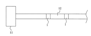
- a plurality of supported filters 2 are arranged in parallel in the axial direction, and the lengths of the catalyst carrier 1 and the outer cylinder 3 securing the length necessary for joining with the exhaust pipe on both sides in the axial direction also become short. Therefore, the catalyst carrier 1 is integrated into the exhaust path of the internal combustion engine and provided at one location to constitute an exhaust gas purification device, and as shown in FIG.
- the catalyst carrier 1 is separated from the exhaust path 12 of the internal combustion engine 11 It is also possible to provide the exhaust gas purification apparatus by providing at a plurality of locations, according to the types of harmful substances such as carbon monoxide (CO), hydrocarbons (HC), nitrogen oxides (NOx), etc. It is also possible to adjust the catalyst substance of each catalyst carrier 1 and install each catalyst carrier 1 in a place where each harmful substance is more likely to cause a catalytic reaction to enhance the overall purification performance. In the case where a plurality of catalyst carriers 1 are collected or separated in the exhaust path, the number of the catalyst-carrying filters 2 in each catalyst carrier 1 can be the same or different.
- the exhaust gas does not collide with the air flow
- the possibility of passing in a short time can be reduced, and the contact between the catalyst substance and the circulating exhaust can be enhanced. Therefore, the excellent purification performance of the catalyst carrier 1 in which the plurality of catalyst-carrying filters 2 in which the catalyst material is supported on the metal mesh laminated porous body is incorporated in the outer cylinder 3 can be more reliably exhibited.
- the exhaust gas easily collides with the catalyst-carrying filter 2, kinetic energy of the exhaust gas can be reduced to obtain the muffling effect of the exhaust gas.
- a plurality of catalyst nets 20 are stacked and sintered, and a plurality of catalyst-carrying filters 2 for dispersing and carrying the catalyst substance are arranged in parallel in the axial direction, longer than the catalyst carrier by the existing honeycomb structure.
- the length of the exhaust passage 12 can be made short, and the degree of freedom and flexibility of the installation location in the exhaust passage 12 can be increased.
- the exhaust flow basically flows through the outer cylinder 3 All can be made to collide with a structure composed of a plurality of catalyst-carrying filters 2, and the time for which the exhaust flow stays in the structure of a plurality of catalyst-carrying filters 2 is further increased, and the catalyst material of the circulating exhaust gas It is possible to further improve the contact performance with the water and the purification performance. In addition, it is possible to prevent the occurrence of a region having low contact with the catalytic substance locally and having a low degree of purification in the exhaust gas flow.
- the engine output performance of the internal combustion engine 11 and the opening area tend to increase as the opening area increases. It becomes easy to set and stabilize the exhaust gas purification performance and the muffling performance, which tend to decrease according to the increase, and it is possible to minimize the variation of the engine output, the muffling and the purification performance.
- the exhaust gas easily collides with the catalyst-carrying filter 2, the muffling effect due to the reduction of kinetic energy of the exhaust gas can be further enhanced.
- the exhaust gas passes straight in a short time without collision of the air flow. It is possible to further reduce the possibility of doing so and to further improve the contact between the catalyst substance and the circulating exhaust and the purification performance.
- the exhaust gas easily collides with the catalyst-carrying filter 2, the muffling effect due to the reduction of kinetic energy of the exhaust gas can be further enhanced.
- the opening areas of the plurality of catalyst-carrying filters 2 in the axial direction of the outer cylinder 3 are 20.9% or less of the inner cross-sectional area of the outer cylinder 3, the convergence tendency of the pressure loss becomes remarkable. , Engine power, noise reduction, and purification performance can be enhanced. Furthermore, in the case where the opening areas of the plurality of catalyst-carrying filters 2 in the axial direction of the outer cylinder 3 are 10% or less, more preferably 5.1% or less of the inner cross sectional area of the outer cylinder 3, The effect can be obtained more reliably.
- the length of the catalyst carrier 1 can be made shorter, and the degree of freedom of the installation place in the exhaust passage 12 and flexibility Sex can be further enhanced.
- the exhaust flow can be kept within the necessary range while the exhaust flow stays in the structure composed of a plurality of catalyst-carrying filters 2 in a necessary range, and the rise in exhaust pressure can be suppressed. The suppression makes it easy to adjust and adapt when it is required to prevent the engine output from decreasing.
- the catalyst-carrying filter 2 by welding in the middle region of the catalyst-carrying filter 2, burn-through and thermal deformation of the catalyst-carrying filter 2 or the metal mesh-laminated porous body in which a plurality of metal mesh 20 are laminated and sintered are prevented.
- the shape of the supported filter 2 can be made into the catalyst carrier 1 maintained.
- the outer peripheral end of the catalyst-carrying filter 2 in which the end faces 21 of the wires are randomly arranged can be welded to the inner peripheral surface of the outer cylinder 3 with high strength. When mounted, sufficient strength that does not break due to heat, vibration, exhaust pressure, etc. can be obtained.
- the catalyst-carrying filter in which the end faces 21 of the wires are randomly arranged is adopted in the case where high strength is required by fixing the catalyst-carrying filter 2 and the outer cylinder 3.
- the outer peripheral end of 2 can be welded to the inner peripheral surface of the outer cylinder 3 with high strength.
- a catalyst carrier 1a according to a second embodiment of the present invention includes a catalyst-carrying filter 2a carrying dispersed catalyst material and a metallic outer cylinder 3a in which a plurality of catalyst-carrying filters 2a are installed.
- the catalyst-carrying filter 2a has the same configuration as the catalyst-carrying filter 2 of the first embodiment, and the outer cylinder 3a has the same configuration as the outer cylinder 3 of the first embodiment except that the length is longer than the outer cylinder 3.
- the plurality of catalyst-carrying filters 2a are arranged in the axial direction and incorporated in the outer cylinder 3a.
- the plurality of five catalyst-carrying filters 2a are arranged in parallel in the axial direction so as to be spaced apart from each other. It is done.
- the distance between the catalyst-carrying filters 2a separated from each other is preferably 3 mm or more, and more preferably 5 mm or more, from the viewpoint of promoting turbulent flow of the exhaust gas.
- at least one catalyst-carrying filter 2a of the plurality of catalyst-carrying filters 2a is spaced apart from the other catalyst-carrying filters 2a.
- a plurality of catalyst-carrying filters 2a can be arranged in the axial direction, and the present invention is not limited to the configuration of the illustrated example of the second embodiment.
- the plurality of catalyst-carrying filters 2a are disposed such that the opening area in the axial direction view of the outer cylinder 3a is smaller than the opening area in the axial direction of the outer cylinder 3a of one catalyst-carrying filter 2a. Also in the second embodiment, the plurality of catalyst-carrying filters 2a are disposed such that the opening areas of the plurality of catalyst-carrying filters 2a in the axial direction of the outer cylinder 3a become zero. As in the modification of the first embodiment, or as a preferable example thereof, it is also possible to adopt a configuration in which the structure of the plurality of catalyst-carrying filters 2a has an opening in the axial direction of the outer cylinder 3a.
- each of the catalyst-carrying filters 2a has the same configuration as that of the first embodiment, and is welded in an intermediate region corresponding to the intermediate region 45 while being substantially in contact with the inner peripheral surface of the outer cylinder 3a.
- the weld bead 41a is formed when laser penetration welding is applied from the outside of the outer cylinder 3a.
- the other configuration is the same as that of the first embodiment.
- the catalyst carrier 1a of the second embodiment the catalyst carrier 1a is integrated to the exhaust path of the internal combustion engine and provided at one location to constitute the exhaust gas purification apparatus, and the catalyst carrier 1a is used as an exhaust path of the internal combustion engine It is possible to provide the exhaust gas purification apparatus by providing at a plurality of spaced places.
- the corresponding effects can be obtained from the configuration corresponding to the first embodiment.
- the distance between the catalyst-carrying filters 2a and 2a can also be utilized to promote turbulent flow of the exhaust flow, and the turbulent flow of the exhaust further enhances the contact between the catalyst substance and the circulating exhaust to improve the purification performance. It can be further improved.
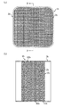
- a catalyst carrier 1b according to a third embodiment of the present invention is made of metal with which a catalyst-carrying filter 2b for dispersing and carrying a catalyst substance and a plurality of catalyst-carrying filters 2b are embedded.
- a cylinder 3b is provided.
- the catalyst-carrying filter 2b has the same configuration as the catalyst-carrying filter 2 of the first embodiment except that the outer shape is not a substantially circular shape but a substantially rectangular shape.
- the outer cylinder 3 b has the same configuration as the outer cylinder 3 of the first embodiment except that the outer cylinder 3 b is not a substantially cylindrical shape but a substantially square cylinder, and the length is slightly longer than the outer cylinder 3.
- a plurality of catalyst-carrying filters 2b are arranged in the axial direction and incorporated in the outer cylinder 3b.
- a plurality of six catalyst-carrying filters 2b are provided in the axial direction of the outer cylinder b in proximity or adjacent to each other. ing.
- a total of six catalyst-carrying filters 2b are internally disposed at a substantially intermediate position in the longitudinal direction of the outer cylinder 3b, and each catalyst-carrying filter 2b is adjacent to or adjacent to and continuous with the outer cylinder 3b. It is juxtaposed inside and provided so as to extend over the entire inner empty cross section of the outer cylinder 3b.
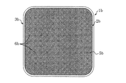
- the plurality of catalyst-carrying filters 2b are disposed such that the opening area in the axial direction view of the outer cylinder 3b is smaller than the opening area in the axial direction of the outer cylinder 3b of one catalyst-carrying filter 2b.
- the plurality of catalyst-carrying filters 2b are disposed such that the opening areas of the plurality of catalyst-carrying filters 2b in the axial direction of the outer cylinder 3b become zero. That is, as shown in FIG. 10, inside the outer cylinder 3b, there is no region where the cylinder by the plurality of catalyst-carrying filters 2b is straight in the axial direction and the cylinder is missed, and this structure allows the inside of the outer cylinder 3b.
- the shielding part 5b is comprised.
- the opening area by the openings 6b of the plurality of catalyst supporting filters 2b in the axial direction of the outer cylinder 3b is preferably 20.9% or less of the inner cross sectional area of the outer cylinder 3b, more preferably It is good to be 10% or less, more preferably 5.1% or less. Further, it is preferable that the openings 6b of the plurality of catalyst-carrying filters 2b in the axial direction of the outer cylinder 3b be disposed in a dispersed manner.
- each of the catalyst-carrying filters 2b has the same configuration as that of the first embodiment, and is welded in the middle region corresponding to the middle region 45 while being substantially in contact with the inner peripheral surface of the outer cylinder 3b.
- the welding bead 41b of b) is formed when the laser penetration welding is performed from the outer side of the outer cylinder 3b.
- the other configuration is the same as that of the first embodiment.
- the catalyst carrier 1b of the third embodiment the catalyst carrier 1b is integrated to the exhaust path of the internal combustion engine and provided at one location to constitute the exhaust gas purification apparatus, and the catalyst carrier 1b is used as an exhaust path of the internal combustion engine It is possible to provide the exhaust gas purification apparatus by providing at a plurality of spaced places.
- the corresponding effects can be obtained from the configuration corresponding to the first embodiment.
- the positions of the wire and the outer sleeves 3, 3a are mutual between the respective catalyst-carrying filters 2 ⁇ 2, 2a ⁇ 2a, 2b ⁇ 2b. It is possible to use a catalyst-carrying filter 2, 2a, 2b having the same or different axial opening position 3b.
- the outer cylinder 3, 3a, 3b is more than the opening area of the outer cylinder 3, 3a, 3b of one catalyst-carrying filter 2, 2a, 2b in the axial direction.
- the plurality of catalyst-carrying filters 2, 2a, 2b in the axial direction view of the outer cylinder 3, 3a, 3b so that the opening areas of the outer cylinders 3, 3a, 3b become zero.
- the configuration for installing a plurality of catalyst supported filters 2, 2a and 2b is appropriate. For example, in the case of a cylindrical outer cylinder 3, 3a, etc., a catalyst-carrying filter 2, 2a, etc.
- a wire extends so as to correspond to a diameter through the center is used. It is possible to arrange in parallel and to arrange in parallel in the axial direction, rotating a plurality of catalyst-carrying filters 2, 2a, etc. using the supported filters 2, 2a, etc. Further, for example, in the case of a square cylindrical outer cylinder 3b etc., a plurality of catalyst-carrying filters 2b etc. are formed so that the heights of wires extending in the lateral direction are made different, and a plurality of catalyst-carrying filters 2b etc. Can be arranged in parallel in the axial direction.
- the number of the catalyst-carrying filters 2, 2a, 2b arranged in parallel should be two or more.
- the number of parallel arrangement is 3 to 12, and more preferably 4 to 8. With this number of juxtapositions, it is possible to more stably ensure high contact between the catalyst substance and the exhaust gas flowing through while suppressing the cost of adding the catalyst-carrying filter 2, 2a, 2b and the like.
- the total thickness of the catalyst-carrying filters 2, 2a, 2b arranged in parallel is preferably 9 mm to 100 mm, and more preferably 12 mm to 50 mm. With this thickness, it is possible to more stably secure high contact between the catalyst substance and the exhaust gas flowing while suppressing the cost of adding the catalyst-carrying filter 2, 2a, 2b, etc.
- the catalyst supports 1, 1 a, 1 b and the like according to the embodiment are also preferably provided at a position upstream of the internal combustion engine 11 in the exhaust passage 12 of the internal combustion engine 11.
- the distance between the internal combustion engine 11 and the end on the internal combustion engine side, such as the catalyst-carrying filter 2, 2a, 2b, etc. closest to the internal combustion engine, such as 1a, 1b, is 0 to 300 mm.
- the catalyst carriers 1, 1a, 1b, etc. of the embodiment are more preferably provided at a position in the vicinity of immediately below the internal combustion engine 11 in the exhaust passage 12 of the internal combustion engine 11.
- the distance between the internal combustion engine 11 and the end on the internal combustion engine side, such as the catalyst-carrying filter 2, 2a, 2b, etc. closest to the internal combustion engine, such as the catalyst carrier 1, 1a, 1b, should be 0 to 100 mm. preferable. Further, in this case, it is also preferable to provide another catalyst carrier 1, 1a, 1b, etc. at a location on the upstream position of the exhaust path 12 at a distance from the catalyst carrier 1, 1b, 1b, etc.
- FIG. 12 is shown as such an example.
- the internal combustion engine 11 and exhaust path 12 of FIG. 12 are the internal combustion engine and exhaust path of a motorcycle, and this exhaust path 12 is composed of an exhaust pipe 12m piped from the outlet of the internal combustion engine 11 and a silencer 12n.
- the catalyst support 1 is provided on an exhaust pipe 12 m piping from the outlet of the internal combustion engine 11, and the exhaust pipe 12 m corresponds to the outer cylinder 3 of the catalyst support 1.
- the catalyst carrier 1 it is possible to use the catalyst carrier of the present invention, such as the catalyst carriers 1a and 1b.
- the catalyst carrier 1, 1a, 1b, etc. which can be compacted in axial dimension and cross-sectional area and installed at a desired location of the exhaust passage 12, is located upstream of the internal combustion engine 11 in the exhaust passage 12, more preferably near directly below As a result, the exhaust gas can be more easily brought into contact with the catalyst substance with almost no loss of exhaust energy, and the exhaust gas performance can be dramatically improved.
- the exhaust pipe 12m piped from the outlet of the internal combustion engine 11 has a complicated layout in which a small diameter and a plurality of bends are added in order to avoid interference with other parts.
- a wire mesh b and a thick wire rectangular frame shifted 1.16 mm in the X direction with a wire mesh b and a wire mesh c and a heavy wire rectangular frame cut 1.74 mm in a X direction with a wire mesh c and a wire mesh As a wire mesh d.
- Four sheets of wire netting selected from these wire nettings a to d were stacked to set a catalyst-carrying filter constituting an analysis model.
- FIGS. 14 (a) to 14 (d) show the catalyst-carrying filter constituting the analysis model, 201 is a wire, and 601 is an opening where the wire 201 does not exist in a front view.
- the catalyst-carrying filter 2f in FIG. 14 (a) is formed by laminating four wire nettings a in the same vertical and horizontal directions, and the opening ratio of the catalyst-carrying filter 2f (total area of openings in front view of catalyst-carrying filter The area of the catalyst-carrying filter corresponding to the thick rectangular frame is 58.6%, which is the same as the opening ratio of the wire mesh a.
- FIG. 14 (a) shows the catalyst-carrying filter constituting the analysis model
- 201 is a wire
- 601 is an opening where the wire 201 does not exist in a front view.
- the catalyst-carrying filter 2f in FIG. 14 (a) is formed by laminating four wire nettings a in the same vertical and horizontal directions, and the
- the catalyst-carrying filter 2h in FIG. 14 (c) is configured by laminating four sheets in the order of the wire mesh a, the wire mesh b, the wire mesh c, and the wire mesh a from the inflow direction F of air with the vertical and horizontal lines in the same direction.
- the opening ratio of the catalyst-carrying filter 2h in a front view is 18.6%.
- the catalyst-carrying filter 2i in FIG. 14 (d) is configured by laminating four sheets in the order of the wire mesh a, the wire mesh b, the wire mesh c, and the wire mesh d from the inflow direction F of air with the vertical and horizontal lines in the same direction.
- the opening ratio of the catalyst-carrying filter 2j in a front view is 0%.
- FIGS. 15 (a) to 15 (d) show the catalyst supported filters 2f ', 2g', 2h 'and 2i' in a state where the catalyst supported filters 2f, 2g, 2h and 2i constituting the analytical model are respectively rotated by 90 degrees. It shows.
- the opening ratios of the catalyst supporting filters 2f ', 2g', 2h 'and 2i' are the same as the opening ratios of the catalyst supporting filters 2f, 2g, 2h and 2i, respectively.
- FIG. 16 (a) shows a structure TP1 (TP1 ') in which two catalyst-carrying filters 2f and a catalyst-carrying filter 2f' are set to overlap in the stacking direction of the wire mesh.
- This structure TP1 (TP1 ') The aperture ratio of the whole front view is 50.4%, which is smaller than the aperture ratio of each of the catalyst-carrying filters 2f and 2f '.
- FIG. 16 (b) shows a structure TP2 (TP2 ') in which two catalyst-carrying filters 2g and a catalyst-carrying filter 2g' are stacked in the stacking direction of the wire mesh, and the entire structure TP2 (TP2 ')
- the aperture ratio in front view is 20.9%, which is smaller than the aperture ratio of each of the catalyst supporting filters 2g and 2g '.
- FIG. 16 (c) shows a structure TP3 (TP3 ') in which two catalyst-carrying filters 2h and a catalyst-carrying filter 2h' are stacked in the stacking direction of the wire mesh, and the entire structure TP3 (TP3 ') The aperture ratio in front view is 5.1% smaller than the aperture ratio of each of the catalyst-carrying filters 2h and 2h '.
- FIG. 16 (d) shows a structure TP4 (TP4 ') in which two catalyst-carrying filters 2i and catalyst-carrying filters 2i' are set so as to overlap in the layering direction of the wire mesh.
- the aperture ratio in front view is 0%, which is the same as the aperture ratio of each of the catalyst-carrying filters 2i and 2i '.
- FIG. 17A shows an analysis model of the structure TP1 in which the catalyst supporting filter 2f and 2f 'are disposed adjacent to each other.
- An analysis model of the catalyst-carrying filter 2f ⁇ 2f ′ having different opening ratios by the structure TP1 an analysis model of the catalyst-carrying filter 2g ⁇ 2g ′ by the structure TP2, an analysis model of the catalyst-carrying filter 2h ⁇ 2h ′ by the structure TP3
- the fluid air (compressible fluid)
- the temperature of the fluid 400 ° C.
- the flow velocity of the fluid 18 m / sec.
- Air was allowed to flow in over the entire area in front view (entire area of 10 mm square), and the pressure loss ⁇ P when air passed through the 10 mm square catalyst-carrying filter structures TP1 to TP4 was determined.
- a thick arrow in FIG. 17A is the inflow direction F of air.
- the exhaust system is assumed in the actual machine, it can be regarded as air in the analysis.
- the flow velocity is assumed to be various depending on, for example, the displacement and the rotation speed of the automobile, the tendency of the relationship of the opening ratio-pressure loss at any flow velocity is valid in other flow velocity regions.
- FIG. 18 shows the analysis result of the analysis model, and is a graph showing the relationship between the opening ratio and the pressure loss in the structures TP1 to TP4 in which the catalyst-carrying filters are disposed adjacent to each other.
- the points of the graph are pressure drop 315.1 Pa of structure TP1 (opening ratio 50.4%), pressure drop 559.1 Pa of structure TP2 (opening ratio 20.9%), structure TP3 (5.1%) Of pressure loss of 690.8 Pa, and pressure drop of 641.4 Pa of structure TP4 (opening ratio 0%).
- the relationship between the pressure loss ⁇ P and the opening ratio in the structures TP1 to TP4 in which the catalyst-carrying filters are disposed adjacent to each other is basically inversely proportional.
- the smaller the opening ratio is the more the fluid comes in contact with the structure of the catalyst-carrying filter, and the exhaust purification performance can be improved in an actual device such as a car. Furthermore, since the kinetic energy of the fluid on the downstream side of the catalyst-supporting filter structure decreases as the aperture ratio decreases, the exhaust silencing effect can be achieved in an actual device such as an automobile. Furthermore, the pressure loss value tends to converge as the opening ratio of the catalyst-supporting filter structure decreases, so that the smaller the opening ratio, the less the variation in engine output, noise reduction, and purification performance can be. it can.
- the aperture ratio is 20.9% or less, preferably 10% or less, more preferably 5.1% or less
- the purification performance and the muffling effect can be further enhanced, and the pressure can be further enhanced. Since the convergence tendency of the loss becomes remarkable, it is possible to further increase the effect of suppressing variations in engine power, noise reduction, and purification performance.
- the above-mentioned aperture ratio corresponds to the open area of the two catalyst-carrying filters in the axial direction of the outer cylinder such as the exhaust pipe of an actual vehicle such as an automobile / the inner cross-sectional area of the outer cylinder.
- the exhaust catalyst can be used for a while for the exhaust gas to stay in the structure composed of a plurality of catalyst-carrying filters. It is possible to keep the contact of the above in a necessary range, to suppress the rise of the exhaust pressure, and to be easily adjusted and adapted when the reduction of the engine output is required by the exhaust pressure suppression.
Landscapes
- Chemical & Material Sciences (AREA)
- Engineering & Computer Science (AREA)
- Chemical Kinetics & Catalysis (AREA)
- Combustion & Propulsion (AREA)
- General Engineering & Computer Science (AREA)
- Health & Medical Sciences (AREA)
- Mechanical Engineering (AREA)
- Biomedical Technology (AREA)
- Toxicology (AREA)
- Environmental & Geological Engineering (AREA)
- Analytical Chemistry (AREA)
- General Chemical & Material Sciences (AREA)
- Oil, Petroleum & Natural Gas (AREA)
- Materials Engineering (AREA)
- Organic Chemistry (AREA)
- Catalysts (AREA)
- Exhaust Gas Treatment By Means Of Catalyst (AREA)
- Exhaust Gas After Treatment (AREA)
Abstract
複数枚の金網20が積層されて焼結された金網積層多孔体で構成され、触媒物質を分散担持する触媒担持フィルター2と、複数個の触媒担持フィルター2が軸方向に並べて内装される外筒3を備え、一個の触媒担持フィルター2の軸方向視の開口面積よりも開口面積が小さくなるように複数個の触媒担持フィルター2が設置されている触媒担体1である。金網積層多孔体に触媒物質を担持させた複数個の触媒担持フィルターを外筒に内装する触媒担体において、触媒物質と排気との接触性を高めることが可能であり、優れた浄化性能をより確実に発揮することができる。
Description
本発明は、自動四輪車や自動二輪車の内燃機関で発生した排気の浄化処理に係り、排気中の有害物質を触媒反応で除去する触媒担体及び排気浄化装置に関する。
従来、内燃機関で発生した排気中に含まれる窒素酸化物等の有害物質の除去に、触媒反応によって除去する触媒担体が用いられている。触媒担体には、ステンレス製の金属板で形成されたハニカム構造体に触媒物質を担持させたものが多く用いられており、例えば特許文献1には、フェライト系耐熱ステンレスの帯状の金属薄板と金属波板を重ねて螺旋状に巻き付けて円柱状のハニカム構造体を形成し、ハニカム構造体の表面に触媒物質を担持させ、触媒物質を担持したハニカム構造体を円筒状の外筒内に挿入した状態とし、このハニカム構造体の両側の外端縁をそれぞれ外筒にレーザー溶接して固定する触媒担体が開示されている。
このハニカム構造体による触媒担体では、有害物質の充分な除去に必要な触媒反応を得るために、触媒物質を担持したハニカム構造体の排気が流通する直線流路を長くする必要がある。そのため、この触媒担体は直線的な厚さやサイズが大きいものとなってしまい、排気経路における設置場所がかなり制約される。
また、触媒担体の厚さを小さくできる可能性のあるものとして、特許文献2の金網積層多孔体がある。この金網積層多孔体は、複数枚の金網が積層されて焼結された多孔体であり、例えばその表面に触媒物質を分散担持したアルミナ薄層が形成されて触媒担持フィルターとされる。特許文献2の金網積層多孔体或いは触媒担持フィルターは、排気の通過する流路を三次元にわたる曲線状にして排気と触媒物質の接触性を高められ、触媒物質を担持したハニカム構造体よりも厚さを大幅に薄くすることが可能である。
ところで、特許文献2における触媒担持フィルターを外筒に内装して触媒担体とする場合、複数個の触媒担持フィルターを外筒の軸方向に並べて外筒に内装することにより、浄化性能にある程度優れる触媒担体を得ることは可能である。しかし、例えば同一形状で同一の開口部位を有する複数個の触媒担持フィルターを軸方向で開口部位の位置を揃えて軸方向に並べて配置した場合、複数個の触媒担持フィルターの軸方向に連通する開口部位を排気が気流の衝突なしで短時間で素通りしてしまう可能性が高くなる。そのため、触媒物質との排気の十分な接触を得ることができず、十分な浄化性能を発揮できない触媒担体となる可能性がある。
本発明は上記課題に鑑み提案するものであり、金網積層多孔体に触媒物質を担持させた複数個の触媒担持フィルターを外筒に内装する触媒担体において、触媒物質と排気との接触性を高めることが可能であり、優れた浄化性能をより確実に発揮することができる触媒担体、及びその触媒担体を備える排気浄化装置を提供することを目的とする。
本発明の触媒担体は、複数枚の金網が積層されて焼結された金網積層多孔体で構成され、触媒物質を分散担持する触媒担持フィルターと、複数個の前記触媒担持フィルターが軸方向に並べて内装される外筒を備え、一個の前記触媒担持フィルターの軸方向視の開口面積よりも開口面積が小さくなるように前記複数個の前記触媒担持フィルターが設置されていることを特徴とする。
これによれば、一個の触媒担持フィルターの軸方向視の開口面積よりも開口面積が小さくなるように複数個の触媒担持フィルターを設置することにより、排気が気流の衝突なしで短時間で素通りしてしまう可能性を低くし、触媒物質と流通する排気との接触性を高めることができる。従って、金網積層多孔体に触媒物質を担持させた複数個の触媒担持フィルターを外筒に内装する触媒担体の優れた浄化性能をより確実に発揮させることができる。また、排気が触媒担持フィルターに衝突し易くなることから、排気の運動エネルギーを低減して排気の消音効果を得ることができる。また、複数枚の金網が積層されて焼結され、触媒物質を分散担持する触媒担持フィルターを複数個軸方向に並設する触媒担体は、既存のハニカム構造体による触媒担体よりも触媒担体の長さを短尺にすることができ、排気経路における設置場所の自由度、柔軟性を高めることができる。
これによれば、一個の触媒担持フィルターの軸方向視の開口面積よりも開口面積が小さくなるように複数個の触媒担持フィルターを設置することにより、排気が気流の衝突なしで短時間で素通りしてしまう可能性を低くし、触媒物質と流通する排気との接触性を高めることができる。従って、金網積層多孔体に触媒物質を担持させた複数個の触媒担持フィルターを外筒に内装する触媒担体の優れた浄化性能をより確実に発揮させることができる。また、排気が触媒担持フィルターに衝突し易くなることから、排気の運動エネルギーを低減して排気の消音効果を得ることができる。また、複数枚の金網が積層されて焼結され、触媒物質を分散担持する触媒担持フィルターを複数個軸方向に並設する触媒担体は、既存のハニカム構造体による触媒担体よりも触媒担体の長さを短尺にすることができ、排気経路における設置場所の自由度、柔軟性を高めることができる。
本発明の触媒担体は、前記外筒の軸方向視における前記複数個の前記触媒担持フィルターの開口面積が前記外筒の内断面積に対して0%以上20.9%以下であることを特徴とする。
これによれば、排気が気流の衝突なしで短時間で素通りしてしまう可能性をより低くし、触媒物質と流通する排気との接触性、浄化性能をより高めることができる。また、排気が触媒担持フィルターにより衝突し易くなることから、排気の運動エネルギーの低減による消音効果をより高めることができる。また、圧力損失の収束傾向が顕著となることから、エンジン出力、消音、浄化の性能のバラつき抑制効果を高めることができる。
これによれば、排気が気流の衝突なしで短時間で素通りしてしまう可能性をより低くし、触媒物質と流通する排気との接触性、浄化性能をより高めることができる。また、排気が触媒担持フィルターにより衝突し易くなることから、排気の運動エネルギーの低減による消音効果をより高めることができる。また、圧力損失の収束傾向が顕著となることから、エンジン出力、消音、浄化の性能のバラつき抑制効果を高めることができる。
本発明の触媒担体は、前記外筒の軸方向視における前記複数個の前記触媒担持フィルターの開口面積が前記外筒の内断面積に対して0%以上10%以下であることを特徴とし、より好適には0%以上5.1%以下であることを特徴とする。
これによれば、触媒物質と流通する排気との接触性、浄化性能、消音効果をより高めることができると共に、エンジン出力、消音、浄化の性能に対するバラつき抑制効果をより確実に得ることができる。
これによれば、触媒物質と流通する排気との接触性、浄化性能、消音効果をより高めることができると共に、エンジン出力、消音、浄化の性能に対するバラつき抑制効果をより確実に得ることができる。
本発明の触媒担体は、前記外筒の軸方向視における前記複数個の前記触媒担持フィルターの開口面積が0となるようにして、前記複数個の前記触媒担持フィルターが設置されていることを特徴とする。
これによれば、基本的に外筒を流れる排気流の全てを複数個の触媒担持フィルターで構成される構造体に衝突させることができ、複数個の触媒担持フィルターの構造体に対して排気流が留まる時間を一層増やし、流通する排気の触媒物質との接触性、浄化性能をより高めることができる。また、排気流の中で局所的に触媒物質との接触性が低く浄化の度合の低い領域が発生することを防止することができる。また、外筒の軸方向視における複数個の触媒担持フィルターの開口面積を0に設定することにより、開口面積の増加に応じて増加傾向となる内燃機関のエンジン出力性能、開口面積の増加に応じて減少傾向となる排気浄化性能、消音性能を安定させて設定しやすくなり、エンジン出力、消音、浄化の性能のバラツキを最小限に抑えることができる。また、排気が触媒担持フィルターにより衝突し易くなることから、排気の運動エネルギーの低減による消音効果をより高めることができる。
これによれば、基本的に外筒を流れる排気流の全てを複数個の触媒担持フィルターで構成される構造体に衝突させることができ、複数個の触媒担持フィルターの構造体に対して排気流が留まる時間を一層増やし、流通する排気の触媒物質との接触性、浄化性能をより高めることができる。また、排気流の中で局所的に触媒物質との接触性が低く浄化の度合の低い領域が発生することを防止することができる。また、外筒の軸方向視における複数個の触媒担持フィルターの開口面積を0に設定することにより、開口面積の増加に応じて増加傾向となる内燃機関のエンジン出力性能、開口面積の増加に応じて減少傾向となる排気浄化性能、消音性能を安定させて設定しやすくなり、エンジン出力、消音、浄化の性能のバラツキを最小限に抑えることができる。また、排気が触媒担持フィルターにより衝突し易くなることから、排気の運動エネルギーの低減による消音効果をより高めることができる。
本発明の触媒担体は、前記外筒の軸方向視における前記複数個の前記触媒担持フィルターの開口部が分散配置されていることを特徴とする。
これによれば、外筒の軸方向視における複数個の触媒担持フィルターの開口部を分散配置することにより、排気流の中で局所的に触媒物質との接触性が低く浄化の度合の低い領域が発生することを防止することができる。
これによれば、外筒の軸方向視における複数個の触媒担持フィルターの開口部を分散配置することにより、排気流の中で局所的に触媒物質との接触性が低く浄化の度合の低い領域が発生することを防止することができる。
本発明の触媒担体は、前記複数個の前記触媒担持フィルターが近接若しくは隣接して軸方向に並べて設けられていることを特徴とする。
これによれば、複数個の触媒担持フィルターを近接若しくは隣接して軸方向に並設することにより、触媒担体の長さをより短尺にすることができ、排気経路における設置場所の自由度、柔軟性を一層高めることができる。また、複数個の触媒担持フィルターで構成される構造体に排気流が留まる時間、排気の触媒物質との接触性を必要な範囲に留め、排圧の上昇を抑制することができ、排圧抑制によってエンジン出力の低下防止が求められる場合に調整、適応し易くすることができる。
これによれば、複数個の触媒担持フィルターを近接若しくは隣接して軸方向に並設することにより、触媒担体の長さをより短尺にすることができ、排気経路における設置場所の自由度、柔軟性を一層高めることができる。また、複数個の触媒担持フィルターで構成される構造体に排気流が留まる時間、排気の触媒物質との接触性を必要な範囲に留め、排圧の上昇を抑制することができ、排圧抑制によってエンジン出力の低下防止が求められる場合に調整、適応し易くすることができる。
本発明の触媒担体は、前記複数個の前記触媒担持フィルターの少なくとも一個の前記触媒担持フィルターが、他の前記触媒担持フィルターと間隔を開けて軸方向に並べて設けられていることを特徴とする。
これによれば、触媒担持フィルター相互の間隔も利用して排気流の乱流化を促進することができ、排気の乱流によって触媒物質と流通する排気との接触性をより高め、浄化性能を一層向上することができる。
これによれば、触媒担持フィルター相互の間隔も利用して排気流の乱流化を促進することができ、排気の乱流によって触媒物質と流通する排気との接触性をより高め、浄化性能を一層向上することができる。
本発明の触媒担体は、前記外筒が金属製であり、各々の前記触媒担持フィルターの外周端が前記外筒の内周面に略当接するように形成され、前記触媒担持フィルターの厚さ方向の中間で周回する中間領域にて、前記触媒担持フィルターの外周端に位置する針金の端面が当接する前記外筒の内周面に溶着されていることを特徴とする。好ましくは、中間領域で、触媒担持フィルターの外周端に位置する針金の端面が当接する外筒の内周面に溶着される溶着部を全周に亘って設けるようにするとよい。
これによれば、触媒担持フィルターの中間領域で溶着することにより、複数枚の金網が積層されて焼結された触媒担持フィルター又は金網積層多孔体の溶接による溶け落ちや熱変形を防止し、触媒担持フィルターの形状が保持された触媒担体とすることができる。また、中間領域にて、針金の端面がランダムに配置された触媒担持フィルターの外周端を外筒の内周面に高強度で溶着された状態にすることができ、排気浄化装置に搭載したときに熱、振動、排圧などで壊れない十分な強度を得ることができる。また、溶着部を全周に亘って設ける場合には、触媒担持フィルターと外筒の固定により高い強度が求められる場合に対応し、針金の端面がランダムに配置された触媒担持フィルターの外周端を外筒の内周面により高い強度で溶着された状態にすることができる。
これによれば、触媒担持フィルターの中間領域で溶着することにより、複数枚の金網が積層されて焼結された触媒担持フィルター又は金網積層多孔体の溶接による溶け落ちや熱変形を防止し、触媒担持フィルターの形状が保持された触媒担体とすることができる。また、中間領域にて、針金の端面がランダムに配置された触媒担持フィルターの外周端を外筒の内周面に高強度で溶着された状態にすることができ、排気浄化装置に搭載したときに熱、振動、排圧などで壊れない十分な強度を得ることができる。また、溶着部を全周に亘って設ける場合には、触媒担持フィルターと外筒の固定により高い強度が求められる場合に対応し、針金の端面がランダムに配置された触媒担持フィルターの外周端を外筒の内周面により高い強度で溶着された状態にすることができる。
本発明の排気浄化装置は、本発明の触媒担体が内燃機関の排気経路の離間した複数箇所に設けられることを特徴とする。
これによれば、本発明の触媒担体の効果を有する排気浄化装置を得ることができると共に、例えば一酸化炭素(CO)、炭化水素(HC)、窒素酸化物(NOx)等の有害物質の種類に合わせて各々の触媒担体の触媒物質を調整し、各々の触媒担体をそれぞれの有害物質がより触媒反応を起こしやすい場所に設置し、全体的な浄化性能を高めることも可能となる。
これによれば、本発明の触媒担体の効果を有する排気浄化装置を得ることができると共に、例えば一酸化炭素(CO)、炭化水素(HC)、窒素酸化物(NOx)等の有害物質の種類に合わせて各々の触媒担体の触媒物質を調整し、各々の触媒担体をそれぞれの有害物質がより触媒反応を起こしやすい場所に設置し、全体的な浄化性能を高めることも可能となる。
本発明の排気浄化装置は、本発明の触媒担体の1つが、内燃機関の排気経路の上流位置に設けられることを特徴とする。この内燃機関の上流位置は、触媒担体の最も内燃機関寄りの触媒担持フィルターの内燃機関側の端部と内燃機関との距離が0~300mmである場合を含む。また、この場合、これと別の本発明の触媒担体を、排気経路の上流位置の触媒担体と離間した箇所に設けても好適である。
これによれば、本発明の触媒担体は軸方向の寸法、断面積ともにコンパクト化し、排気経路の所望箇所に設置することが可能であり、内燃機関の上流位置に触媒担体を配置することで、排気のエネルギーを殆ど損失することなく、排気の触媒物質への接触性を高めることができ、排ガス性能を飛躍的に向上することができる。
これによれば、本発明の触媒担体は軸方向の寸法、断面積ともにコンパクト化し、排気経路の所望箇所に設置することが可能であり、内燃機関の上流位置に触媒担体を配置することで、排気のエネルギーを殆ど損失することなく、排気の触媒物質への接触性を高めることができ、排ガス性能を飛躍的に向上することができる。
本発明の排気浄化装置は、自動二輪車の内燃機関の出口から配管されるエギゾーストパイプの上流位置に前記触媒担体が設けられることを特徴とする。
これによれば、自動二輪車の場合、内燃機関の出口から配管されるエギゾーストパイプは、他部品との干渉を避けるため、小径かつ複数の曲げが加わった複雑なレイアウトとなり、ここに軸方向に長い既存のメタル担体等を搭載することは寸法上の制約から困難であるが、本発明の触媒担体による上記排気浄化装置は、そのコンパクト性から、斯様な寸法上の制約がある自動二輪車のエギゾーストパイプでも設置することが可能である。
これによれば、自動二輪車の場合、内燃機関の出口から配管されるエギゾーストパイプは、他部品との干渉を避けるため、小径かつ複数の曲げが加わった複雑なレイアウトとなり、ここに軸方向に長い既存のメタル担体等を搭載することは寸法上の制約から困難であるが、本発明の触媒担体による上記排気浄化装置は、そのコンパクト性から、斯様な寸法上の制約がある自動二輪車のエギゾーストパイプでも設置することが可能である。
本発明によれば、金網積層多孔体に触媒物質を担持させた複数個の触媒担持フィルターを外筒に内装する触媒担体において、触媒物質と排気との接触性を高めることができ、優れた浄化性能を確実に発揮させることができる。
〔第1実施形態の触媒担体〕
本発明による第1実施形態の触媒担体1は、図1及び図2に示すように、触媒物質を分散担持する触媒担持フィルター2と、触媒担持フィルター2が内装される金属製の外筒3を備える。触媒担持フィルター2は、複数枚の金網20が積層されて焼結された金網積層多孔体で構成されており、図示例では、5枚の金網20が5層に積層されて焼結されることで金網積層多孔体が形成され、この金網積層多孔体に触媒物質が分散担持されている。そして、複数個の触媒担持フィルター2が軸方向に並べられて外筒3に内装されている。
本発明による第1実施形態の触媒担体1は、図1及び図2に示すように、触媒物質を分散担持する触媒担持フィルター2と、触媒担持フィルター2が内装される金属製の外筒3を備える。触媒担持フィルター2は、複数枚の金網20が積層されて焼結された金網積層多孔体で構成されており、図示例では、5枚の金網20が5層に積層されて焼結されることで金網積層多孔体が形成され、この金網積層多孔体に触媒物質が分散担持されている。そして、複数個の触媒担持フィルター2が軸方向に並べられて外筒3に内装されている。
各々の触媒担持フィルター2の外周端は、外筒3の内周面31に略当接するように形成されている。図示例における外筒3は、ステンレス等の金属で略円筒形の短筒状に形成され、その板厚はt2である。そして、略円形の触媒担持フィルター2の外周端の外径は外筒3の内径と略同一に形成され、外筒3の内周面31に略当接するようになっている。
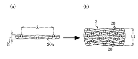
触媒担持フィルター2は、例えば針金の周期的な繰り返しパターンの波長λ、最大の厚さに相当する針金の繰り返しパターンの波高hの略矩形の金網20a(図3(a)参照)を互いの凹凸が入り込むようにして積層層n=5で積層し、積層された略矩形の金網20aを円形に切断して形成され、その厚さt1は波高h×積層数nよりも小さくなっている(図2、図3(b)参照)。金網20aを円形に切断して形成された略円形の金網20で構成される略円形の触媒担持フィルター2では、その外周端の位置で切断面である針金の端面21が露出しており、この針金の端面21が外筒3の内周面31に略当接される。
各々の触媒担持フィルター2は、図4に示すように、その厚さ方向の中間で周回する中間領域45にて、触媒担持フィルター2の外周端に位置する針金の端面21が当接する外筒3の内周面31に溶着部42で溶着されている。本実施形態では、中間領域45で、触媒担持フィルター2の外周端に位置する針金の端面21が当接する外筒3の内周面31に溶着される溶着部42が全周に亘って設けられており、外周端で露出し且つ中間領域45内に位置する部分で、外筒3の内周面31に当接する針金の端面21が溶着部42でランダムに外筒3の内周面31に溶着されている。尚、中間領域45で、針金の端面21以外の金網20の部分が当接する外筒3の内周面31に溶着された部分が、針金の端面21の溶着部42と併存する構成としてもよい。
この中間領域45は、触媒担持フィルター2の3枚以上の複数の金網20が積層されて構成される金網層のうち、中間層である一層の金網20の波高hと位置、幅を略対応させると好適であり、図示例における中間領域45は、金網20が5層に積層された金網層のうち、中央に位置する3層目の金網20の波高hと位置、幅を略対応するように設定され、中間領域45の幅Wは金網20の波高hと略同一になっている。そして、3層目の金網20と略対応する中間領域45内で外筒3の内周面31に当接する触媒担持フィルター2の針金の端面21、或いは端面21の一部が、溶着部42で外筒3の内周面31に溶着されている。
また、図1、図2中の41は溶接ビードであり、触媒担持フィルター2の針金の端面21或いは端面21の一部と外筒3の内周面31を溶着部42で溶着する際に、外筒3の外側からレーザー貫通溶接を施した際に形成されたものである。溶接ビード41の外筒3の内周面31の幅は中間領域45の幅Wと略対応しており、外筒3の内周面31の溶接幅が中間領域45の幅Wになるようにしてレーザー貫通溶接が施されている。
外筒3に内装される複数個の触媒担持フィルター2は、近接若しくは隣接して外筒3の軸方向に並べて設けられている。図示例では、合計5個の触媒担持フィルター2が外筒3の長さ方向における略中間位置に内装して配置されており、各々の触媒担持フィルター2は、近接若しくは隣接して連続するように外筒3の内部に並設され、外筒3の内空断面の全体に拡がるように設けられている。
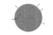
複数個の触媒担持フィルター2は、一個の触媒担持フィルター2の外筒3の軸方向視における開口面積よりも、外筒3の軸方向視における開口面積が小さくなるように設置されており、第1実施形態では、外筒3の軸方向視における複数個の触媒担持フィルター2の開口面積が0となるようにして、複数個の触媒担持フィルター2が設置されている。
即ち、図5に示すように、外筒3の内部には、複数個の触媒担持フィルター2による構造体によって軸方向に直線状で筒抜けになる部位が無く、この構造体によって外筒3の内部に遮蔽部5が構成されている。そして、遮蔽部5により、外筒3の軸方向視における複数個の触媒担持フィルター2の開口面積が0となっており、外筒3の内部に軸方向に可視光を当てた場合に直線光が通り抜けないようになっている。
尚、第1実施形態の変形例として、図6に示すように、外筒3の軸方向視において複数個の触媒担持フィルター2による構造体が開口部6を有する構成とすることも可能である。この場合、外筒3の軸方向視における複数個の前記触媒担持フィルター2の開口部6による開口面積は、外筒3の内断面積の20.9%以下とすると良好であり、より好ましくは10%以下、より一層好ましくは5.1%以下とするとよい。また、外筒3の軸方向視における複数個の触媒担持フィルター2の開口部6は分散配置するように構成することが好ましい。
第1実施形態やその変形例の触媒担体1における触媒担持フィルター2は、複数の金網20の積層状態における厚さt1が例えば3mm~20mm程度、図示例では3mm~6mm程度で薄く、この薄い触媒担持フィルター2を複数個、軸方向に並設し、その軸方向の両側に排気管との接合に必要な長さを確保した触媒担体1や外筒3の長さも短くなる。従って、触媒担体1を内燃機関の排気経路に集約して一カ所に設けて排気浄化装置を構成することの他、図7に示すように、触媒担体1を内燃機関11の排気経路12の離間した複数箇所に設けて排気浄化装置を構成することも可能であり、これにより、例えば一酸化炭素(CO)、炭化水素(HC)、窒素酸化物(NOx)等の有害物質の種類に合わせて各々の触媒担体1の触媒物質を調整し、各々の触媒担体1をそれぞれの有害物質がより触媒反応を起こしやすい場所に設置し、全体的な浄化性能を高めることも可能となる。尚、複数の触媒担体1を排気経路に集約或いは離間して設ける場合、各触媒担体1の触媒担持フィルター2の並設する数は同数或いは異なる数とすることが可能である。
第1実施形態によれば、一個の触媒担持フィルター2の軸方向視の開口面積よりも開口面積が小さくなるように複数個の触媒担持フィルター2を設置することにより、排気が気流の衝突なしで短時間で素通りしてしまう可能性を低くし、触媒物質と流通する排気との接触性を高めることができる。従って、金網積層多孔体に触媒物質を担持させた複数個の触媒担持フィルター2を外筒3に内装する触媒担体1の優れた浄化性能をより確実に発揮させることができる。また、排気が触媒担持フィルター2に衝突し易くなることから、排気の運動エネルギーを低減して排気の消音効果を得ることができる。また、複数枚の金網20が積層されて焼結され、触媒物質を分散担持する触媒担持フィルター2を複数個軸方向に並設する触媒担体1は、既存のハニカム構造体による触媒担体よりも長さを短尺にすることができ、排気経路12における設置場所の自由度、柔軟性を高めることができる。
また、外筒3の軸方向視における複数個の触媒担持フィルター2の開口面積が0となるようにして複数個の触媒担持フィルター2を設置する場合、基本的に外筒3を流れる排気流の全てを複数個の触媒担持フィルター2で構成される構造体に衝突させることができ、複数個の触媒担持フィルター2の構造体に対して排気流が留まる時間を一層増やし、流通する排気の触媒物質との接触性、浄化性能をより高めることができる。また、排気流の中で局所的に触媒物質との接触性が低く浄化の度合の低い領域が発生することを防止することができる。また、外筒3の軸方向視における複数個の触媒担持フィルター2の開口面積を0に設定することにより、開口面積の増加に応じて増加傾向となる内燃機関11のエンジン出力性能、開口面積の増加に応じて減少傾向となる排気浄化性能、消音性能を安定させて設定しやすくなり、エンジン出力、消音、浄化の性能のバラツキを最小限に抑えることができる。また、排気が触媒担持フィルター2により衝突し易くなることから、排気の運動エネルギーの低減による消音効果をより高めることができる。
また、外筒3の軸方向視における複数個の触媒担持フィルター2の開口面積を外筒3の内断面積の20.9%以下とすることにより、排気が気流の衝突なしで短時間で素通りしてしまう可能性をより低くし、触媒物質と流通する排気との接触性、浄化性能をより高めることができる。また、排気が触媒担持フィルター2により衝突し易くなることから、排気の運動エネルギーの低減による消音効果をより高めることができる。また、外筒3の軸方向視における複数個の触媒担持フィルター2の開口面積を外筒3の内断面積の20.9%以下とする場合には圧力損失の収束傾向が顕著となることから、エンジン出力、消音、浄化の性能のバラつき抑制効果を高めることができる。更に、外筒3の軸方向視における複数個の触媒担持フィルター2の開口面積を外筒3の内断面積の10%以下、より好適には5.1%以下とする場合には、これらの効果をより確実に得ることができる。また、外筒3の軸方向視における複数個の触媒担持フィルター2の開口部6を分散配置する場合には、排気流の中で局所的に触媒物質との接触性が低く浄化の度合の低い領域が発生することを防止することができる。
また、複数個の触媒担持フィルター2を近接若しくは隣接して軸方向に並設することにより、触媒担体1の長さをより短尺にすることができ、排気経路12における設置場所の自由度、柔軟性を一層高めることができる。また、複数個の触媒担持フィルター2で構成される構造体に排気流が留まる時間、排気の触媒物質との接触性を必要な範囲に留め、排圧の上昇を抑制することができ、排圧抑制によってエンジン出力の低下防止が求められる場合に調整、適応し易くすることができる。
また、触媒担持フィルター2の中間領域で溶着することにより、複数枚の金網20が積層されて焼結された触媒担持フィルター2又は金網積層多孔体の溶接による溶け落ちや熱変形を防止し、触媒担持フィルター2の形状が保持された触媒担体1とすることができる。また、中間領域にて、針金の端面21がランダムに配置された触媒担持フィルター2の外周端を外筒3の内周面に高強度で溶着された状態にすることができ、排気浄化装置に搭載したときに熱、振動、排圧などで壊れない十分な強度を得ることができる。また、溶着部42を全周に亘って設ける場合には、触媒担持フィルター2と外筒3の固定により高い強度が求められる場合に対応し、針金の端面21がランダムに配置された触媒担持フィルター2の外周端を外筒3の内周面により高い強度で溶着された状態にすることができる。
〔第2実施形態の触媒担体〕
本発明による第2実施形態の触媒担体1aは、図8に示すように、触媒物質を分散担持する触媒担持フィルター2aと、複数個の触媒担持フィルター2aが内装される金属製の外筒3aを備える。触媒担持フィルター2aは第1実施形態の触媒担持フィルター2と同一構成であり、外筒3aは長さが外筒3よりも長いこと以外は第1実施形態の外筒3と同一構成である。
本発明による第2実施形態の触媒担体1aは、図8に示すように、触媒物質を分散担持する触媒担持フィルター2aと、複数個の触媒担持フィルター2aが内装される金属製の外筒3aを備える。触媒担持フィルター2aは第1実施形態の触媒担持フィルター2と同一構成であり、外筒3aは長さが外筒3よりも長いこと以外は第1実施形態の外筒3と同一構成である。
複数個の触媒担持フィルター2aは軸方向に並べて外筒3aに内装され、図示例では、複数個である5個の触媒担持フィルター2aの各々が相互に間隔を開けるようにして軸方向に並設されている。離間する触媒担持フィルター2a相互の間隔は、排気の乱流化を促進する観点からは、3mm以上とするとよく、5mm以上とするとより好ましい。また、複数個の触媒担持フィルター2aを離間して間隔を開けて設ける場合、複数個の触媒担持フィルター2aの少なくとも一個の触媒担持フィルター2aを他の触媒担持フィルター2aと間隔を開けるようにして、複数個の触媒担持フィルター2aを軸方向に並べて設ける構成とすることが可能であり、第2実施形態の図示例の構成に限定されない。
複数個の触媒担持フィルター2aは、一個の触媒担持フィルター2aの外筒3aの軸方向視における開口面積よりも、外筒3aの軸方向視における開口面積が小さくなるように設置されており、第2実施形態でも、外筒3aの軸方向視における複数個の触媒担持フィルター2aの開口面積が0となるようにして、複数個の触媒担持フィルター2aが設置されている。尚、第1実施形態の変形例、更にその好ましい例のように、外筒3aの軸方向視において複数個の触媒担持フィルター2aによる構造体が開口部を有する構成とすることも可能である。
各々の触媒担持フィルター2aの外周端は、第1実施形態と同一構成で、外筒3aの内周面に略当接されて中間領域45に相当する中間領域で溶着されており、図8の溶接ビード41aは外筒3aの外側からレーザー貫通溶接を施した際に形成されたものである。その他の構成は第1実施形態と同様である。また、第2実施形態の触媒担体1aを用い、触媒担体1aを内燃機関の排気経路に集約して一カ所に設けて排気浄化装置を構成することの他、触媒担体1aを内燃機関の排気経路の離間した複数箇所に設けて排気浄化装置を構成することが可能である。
第2実施形態によれば、第1実施形態と対応する構成から対応する効果を得ることができる。また、触媒担持フィルター2a・2a相互の間隔も利用して排気流の乱流化を促進することができ、排気の乱流によって触媒物質と流通する排気との接触性をより高め、浄化性能を一層向上することができる。
〔第3実施形態の触媒担体〕
本発明による第3実施形態の触媒担体1bは、図9及び図10に示すように、触媒物質を分散担持する触媒担持フィルター2bと、複数個の触媒担持フィルター2bが内装される金属製の外筒3bを備える。触媒担持フィルター2bは、外形が略円形ではなく略矩形であること以外は第1実施形態の触媒担持フィルター2と同一構成である。外筒3bは、略円筒形ではなく略四角筒形であること、長さが外筒3よりも若干長いこと以外は第1実施形態の外筒3と同一構成である。
本発明による第3実施形態の触媒担体1bは、図9及び図10に示すように、触媒物質を分散担持する触媒担持フィルター2bと、複数個の触媒担持フィルター2bが内装される金属製の外筒3bを備える。触媒担持フィルター2bは、外形が略円形ではなく略矩形であること以外は第1実施形態の触媒担持フィルター2と同一構成である。外筒3bは、略円筒形ではなく略四角筒形であること、長さが外筒3よりも若干長いこと以外は第1実施形態の外筒3と同一構成である。
複数個の触媒担持フィルター2bは軸方向に並べて外筒3bに内装され、図示例では、複数個である6個の触媒担持フィルター2bが近接若しくは隣接して外筒bの軸方向に並べて設けられている。合計6個の触媒担持フィルター2bは外筒3bの長さ方向における略中間位置に内装して配置されており、各々の触媒担持フィルター2bは、近接若しくは隣接して連続するように外筒3bの内部に並設され、外筒3bの内空断面の全体に拡がるように設けられている。
複数個の触媒担持フィルター2bは、一個の触媒担持フィルター2bの外筒3bの軸方向視における開口面積よりも、外筒3bの軸方向視における開口面積が小さくなるように設置されており、第3実施形態では、外筒3bの軸方向視における複数個の触媒担持フィルター2bの開口面積が0となるようにして、複数個の触媒担持フィルター2bが設置されている。即ち、図10に示すように、外筒3bの内部には、複数個の触媒担持フィルター2bによる構造体によって軸方向に直線状で筒抜けになる部位が無く、この構造体によって外筒3bの内部に遮蔽部5bが構成されている。
尚、第1実施形態の変形例と同様、図11のように、外筒3bの軸方向視において複数個の触媒担持フィルター2bによる構造体が開口部6bを有する構成とすることも可能である。この場合、外筒3bの軸方向視における複数個の前記触媒担持フィルター2bの開口部6bによる開口面積は、外筒3bの内断面積の20.9%以下とすると良好であり、より好ましくは10%以下、より一層好ましくは5.1%以下とするとよい。また、外筒3bの軸方向視における複数個の触媒担持フィルター2bの開口部6bは分散配置するように構成することが好ましい。
各々の触媒担持フィルター2bの外周端は、第1実施形態と同一構成で、外筒3bの内周面に略当接されて中間領域45に相当する中間領域で溶着されており、図9(b)の溶接ビード41bは外筒3bの外側からレーザー貫通溶接を施した際に形成されたものである。その他の構成は第1実施形態と同様である。また、第3実施形態の触媒担体1bを用い、触媒担体1bを内燃機関の排気経路に集約して一カ所に設けて排気浄化装置を構成することの他、触媒担体1bを内燃機関の排気経路の離間した複数箇所に設けて排気浄化装置を構成することが可能である。
第3実施形態によれば、第1実施形態と対応する構成から対応する効果を得ることができる。
〔本明細書開示発明の包含範囲〕
本明細書開示の発明は、発明として列記した各発明、各実施形態及びその変形例の他に、適用可能な範囲で、これらの部分的な内容を本明細書開示の他の内容に変更して特定したもの、或いはこれらの内容に本明細書開示の他の内容を付加して特定したもの、或いはこれらの部分的な内容を部分的な作用効果が得られる限度で削除して上位概念化して特定したものを包含する。そして、本明細書開示の発明には下記変形例や追記した内容も含まれる。
本明細書開示の発明は、発明として列記した各発明、各実施形態及びその変形例の他に、適用可能な範囲で、これらの部分的な内容を本明細書開示の他の内容に変更して特定したもの、或いはこれらの内容に本明細書開示の他の内容を付加して特定したもの、或いはこれらの部分的な内容を部分的な作用効果が得られる限度で削除して上位概念化して特定したものを包含する。そして、本明細書開示の発明には下記変形例や追記した内容も含まれる。
例えば軸方向に並べて設けられる複数個の触媒担持フィルター2、2a、2bについて、各触媒担持フィルター2・2相互、2a・2a相互、2b・2b相互には、針金の位置及び外筒3、3a、3bの軸方向の開口位置が同一又は異なる触媒担持フィルター2、2a、2bを用いることが可能である。
また、複数個の触媒担持フィルター2、2a、2bで、一個の触媒担持フィルター2、2a、2bの外筒3、3a、3bの軸方向視における開口面積よりも、外筒3、3a、3bの軸方向視における開口面積が小さくなるように設置する構成、更には外筒3、3a、3bの軸方向視における複数個の触媒担持フィルター2、2a、2bの開口面積が0となるようにして複数個の触媒担持フィルター2、2a、2bを設置する構成等は適宜である。例えば円筒形の外筒3、3a等の場合には、中心を通って直径に相当するように針金が延びる触媒担持フィルター2、2a等を用い、これと針金の位置及び開口位置が同一の触媒担持フィルター2、2a等を用い、複数個の触媒担持フィルター2、2a等を回転させながら軸方向に並べて並設する構成とすることが可能である。また、例えば四角筒形の外筒3b等の場合には、横方向に延びる針金の高さを異ならせるようにして複数個の触媒担持フィルター2b等を形成し、複数個の触媒担持フィルター2b等を軸方向に並べて並設する構成とすることが可能である。
また、複数個の触媒担持フィルター2、2a、2bを外筒3の軸方向に並べて内装する場合、並設する触媒担持フィルター2、2a、2bの数は2個以上の複数であれば適宜であるが、この並設数は3個~12個とすると好ましく、更には4個~8個とするとより好ましい。この並設数により、触媒担持フィルター2、2a、2b等の増設コストを抑制しつつ、触媒物質と流通する排気との高度な接触性をより安定して確保することができる。
また、複数個の触媒担持フィルター2、2a、2bを外筒3の軸方向に並べて内装する場合、並設する触媒担持フィルター2、2a、2bの合計の厚さ(外筒3の軸方向の長さの合計)は9mm~100mmとすると好ましく、更には12mm~50mmとするとより好ましい。この厚さにより、触媒担持フィルター2、2a、2b等の増設コストを抑制しつつ、触媒物質と流通する排気との高度な接触性をより安定して確保することができる。
また、実施形態の触媒担体1、1a、1b等は、内燃機関11の排気経路12における内燃機関11の上流位置に設ける構成としても好適であり、この内燃機関11の上流位置は、触媒担体1、1a、1b等の最も内燃機関寄りの触媒担持フィルター2、2a、2b等の内燃機関側の端部と内燃機関11との距離が0~300mmとなるようにすることが好ましい。更に、実施形態の触媒担体1、1a、1b等は、内燃機関11の排気経路12における内燃機関11の直下近傍の位置に設ける構成とするとより好適であり、この内燃機関11の直下近傍の位置は、触媒担体1、1a、1b等の最も内燃機関寄りの触媒担持フィルター2、2a、2b等の内燃機関側の端部と内燃機関11との距離が0~100mmとなるようにすることが好ましい。また、この場合、これと別の触媒担体1、1a、1b等を、排気経路12の上流位置の触媒担体1、1b、1b等と離間した箇所に設けても好適である。
このような例として図12を示す。図12の内燃機関11、排気経路12は自動二輪車の内燃機関、排気経路であり、この排気経路12は、内燃機関11の出口から配管されるエギゾーストパイプ12mと、サイレンサー12nとから構成されている。触媒担体1は、内燃機関11の出口から配管されるエギゾーストパイプ12mに設けられ、エギゾーストパイプ12mが触媒担体1の外筒3に相当するようになっている。尚、触媒担体1に代え、触媒担体1a、1b等の本発明の触媒担体を用いることが可能である。
軸方向の寸法、断面積ともにコンパクト化して排気経路12の所望箇所に設置することが可能な触媒担体1、1a、1b等を、排気経路12における内燃機関11の上流位置、より好ましくは直下近傍に設けることにより、排気のエネルギーを殆ど損失することなく、排気の触媒物質への接触性を高めることができ、排ガス性能を飛躍的に向上することができる。特に、自動二輪車の場合、内燃機関11の出口から配管されるエギゾーストパイプ12mは、他部品との干渉を避けるため、小径かつ複数の曲げが加わった複雑なレイアウトとなり、ここに軸方向に長い既存のメタル担体等を搭載することは寸法上の制約から困難であるが、触媒担体1、1a、1b等による上記排気浄化装置は、そのコンパクト性から、斯様な寸法上の制約がある自動二輪車のエギゾーストパイプ12mでも設置することが可能である。
〔本発明による触媒担体のCAE解析及びその解析結果〕
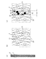
本発明による触媒担体に対応する解析モデルを設定し、SCRYU/Tetra(株式会社ソフトウェアクレイドル製)を用いてCAE解析を行った。解析の前提として、図13に示すように、針金201の線径Φ0.58mm、12-6MESH(1インチ四方に縦線12本の針金と横線6本の針金の平織)の金網を設定した。そして、図13の金網を縦L1=10mm、横L2=10mmの10mm四方の太線矩形枠で切断したものを金網aとし、金網aを基準に太線矩形枠をX方向に0.58mmずらして切断したものを金網b、金網aを基準に太線矩形枠をX方向に1.16mmずらして切断したものを金網c、金網aを基準に太線矩形枠をX方向に1.74mmずらして切断したものを金網dとした。これらの金網a~dのうちから選択した4枚の金網を積層して、解析モデルを構成する触媒担持フィルターを設定した。
本発明による触媒担体に対応する解析モデルを設定し、SCRYU/Tetra(株式会社ソフトウェアクレイドル製)を用いてCAE解析を行った。解析の前提として、図13に示すように、針金201の線径Φ0.58mm、12-6MESH(1インチ四方に縦線12本の針金と横線6本の針金の平織)の金網を設定した。そして、図13の金網を縦L1=10mm、横L2=10mmの10mm四方の太線矩形枠で切断したものを金網aとし、金網aを基準に太線矩形枠をX方向に0.58mmずらして切断したものを金網b、金網aを基準に太線矩形枠をX方向に1.16mmずらして切断したものを金網c、金網aを基準に太線矩形枠をX方向に1.74mmずらして切断したものを金網dとした。これらの金網a~dのうちから選択した4枚の金網を積層して、解析モデルを構成する触媒担持フィルターを設定した。
図14(a)~(d)は解析モデルを構成する触媒担持フィルターを示しており、201は針金、601は正面視で針金201が存在しない開口部である。図14(a)における触媒担持フィルター2fは金網aを縦横方向を同じにして4枚積層して構成され、触媒担持フィルター2fの開口率(触媒担持フィルターの正面視における開口部の面積の合計/太線矩形枠に対応する触媒担持フィルターの面積)は、金網aの開口率と同一で58.6%である。図14(b)における触媒担持フィルター2gは、後述する空気の流入方向Fから金網a、金網b、金網a、金網bの順で、それぞれ縦線と横線の方向を同じにして4枚積層して構成され、触媒担持フィルター2gの正面視の開口率は37.7%になっている。
図14(c)における触媒担持フィルター2hは、空気の流入方向Fから金網a、金網b、金網c、金網aの順で、それぞれ縦線と横線の方向を同じにして4枚積層して構成され、触媒担持フィルター2hの正面視の開口率は18.6%になっている。図14(d)における触媒担持フィルター2iは、空気の流入方向Fから金網a、金網b、金網c、金網dの順で、それぞれ縦線と横線の方向を同じにして4枚積層して構成され、触媒担持フィルター2jの正面視の開口率は0%になっている。
更に、図15(a)~(d)は解析モデルを構成する触媒担持フィルター2f、2g、2h、2iをそれぞれ90度回転した状態の触媒担持フィルター2f’、2g’、2h’、2i’を示している。触媒担持フィルター2f’、2g’、2h’、2i’の開口率は触媒担持フィルター2f、2g、2h、2iの開口率とそれぞれ同一である。
更に、図16(a)は2個の触媒担持フィルター2fと触媒担持フィルター2f’を金網の積層方向に重ねて設定した構造体TP1(TP1’)であり、この構造体TP1(TP1’)の全体の正面視の開口率は触媒担持フィルター2f、2f’のそれぞれの開口率よりも小さい50.4%になっている。図16(b)は2個の触媒担持フィルター2gと触媒担持フィルター2g’を金網の積層方向に重ねて設定した構造体TP2(TP2’)であり、この構造体TP2(TP2’)の全体の正面視の開口率は触媒担持フィルター2g、2g’のそれぞれの開口率よりも小さい20.9%になっている。
図16(c)は2個の触媒担持フィルター2hと触媒担持フィルター2h’を金網の積層方向に重ねて設定した構造体TP3(TP3’)であり、この構造体TP3(TP3’)の全体の正面視の開口率は触媒担持フィルター2h、2h’のそれぞれの開口率よりも小さい5.1%になっている。図16(d)は2個の触媒担持フィルター2iと触媒担持フィルター2i’を金網の積層方向に重ねて設定した構造体TP4(TP4’)であり、この構造体TP4(TP4’)の全体の正面視の開口率は触媒担持フィルター2i、2i’のそれぞれの開口率と同じ0%になっている。
そして、触媒担持フィルター2f・2f’を隣接配置した構造体TP1、触媒担持フィルター2g・2g’を隣接配置した構造体TP2、触媒担持フィルター2h・2h’を隣接配置した構造体TP3、触媒担持フィルター2i・2i’を隣接配置した構造体TP4を、それぞれ長さS3=9.3mmの設置区間に設定し、設置区間に設定した構造体TP1~TP4における流体流入側に流体の流れを安定化する長さS1=50mmの助走区間を設定すると共に、設置区間に設定した構造体TP1~TP4における流体流出側に流体の流れを安定化する長さS2=50mmの助走区間を設定し、解析モデルとした。図17(a)は触媒担持フィルター2f・2f’を隣接配置した構造体TP1の解析モデルを示している。
これらの開口率が異なる触媒担持フィルター2f・2f’の構造体TP1による解析モデル、触媒担持フィルター2g・2g’の構造体TP2による解析モデル、触媒担持フィルター2h・2h’の構造体TP3による解析モデル、触媒担持フィルター2i・2i’の構造体による解析モデルTP4に対し、流体:空気(圧縮性流体)、流体の温度:400℃、流体の流速:18m/secとして、各構造体TP1~TP4の正面視の領域全体(10mm四方の領域全体)に亘って空気を流入させ、10mm四方の各触媒担持フィルター構造体TP1~TP4を空気が通過するときの圧力損失ΔPを求めた。図17(a)の太線矢印は空気の流入方向Fである。尚、実機は排気が想定されるが、解析上は空気と同視することができる。また、流速は、例えば自動車の排気量や回転数に応じて様々なものが想定されるが、任意の流速における開口率-圧力損失の関係の傾向は他の流速域でも妥当する。
図18は解析モデルの解析結果を示すものであり、触媒担持フィルターを隣接配置した構造体TP1~TP4における開口率と圧力損失の関係を示すグラフである。グラフの点は、構造体TP1(開口率50.4%)の圧力損失315.1Pa、構造体TP2(開口率20.9%)の圧力損失559.1Pa、構造体TP3(5.1%)の圧力損失690.8Pa、構造体TP4(開口率0%)の圧力損失641.4Paを示している。このグラフから明らかなように、触媒担持フィルターを隣接配置した構造体TP1~TP4における圧力損失△Pと開口率の関係は基本的に反比例することが分かる。即ち、開口率が小さい方が流体が触媒担持フィルターの構造体に多く接触することを示しており、自動車等の実機において排気の浄化性能の向上を図ることができる。更に、触媒担持フィルターの構造体の下流側の流体の運動エネルギーは、開口率が小さい方が小さくなるため、自動車等の実機において排気の消音効果を図ることができる。更に、圧力損失の値は、触媒担持フィルターの構造体の開口率が小さくなるにつれ収束する傾向があることから、開口率が小さいほど、エンジン出力、消音、浄化の性能のバラつきを抑制することができる。
特に開口率が20.9%以下とする場合、好ましくは10%以下とする場合、より好ましくは5.1%以下とする場合には、浄化性能、消音効果をより高めることができると共に、圧力損失の収束傾向が顕著となることから、エンジン出力、消音、浄化の性能のバラつき抑制効果を一層高くすることができる。尚、前述の開口率は、自動車等の実機における排気管等の外筒の軸方向視における複数個である2個の触媒担持フィルターの開口面積/外筒の内断面積に相当する。
また、別の解析モデルとして、触媒担持フィルター2f・2f’を離間配置した構造体TP1’、触媒担持フィルター2g・2g’を離間配置した構造体TP2’、触媒担持フィルター2h・2h’を離間配置した構造体TP3’、触媒担持フィルター2i・2i’を離間配置した構造体TP4’を、それぞれ長さS3=14.3mmの設置区間に離間距離S4=5mm離間して設定し、設置区間に設定した構造体TP1’~TP4’における流体流入側に流体の流れを安定化する長さS1=50mmの助走区間を設定すると共に、設置区間に設定した構造体TP1’~TP4’における流体流出側に流体の流れを安定化する長さS2=50mmの助走区間を設定した。図17(b)は触媒担持フィルター2f・2f’を離間配置した構造体TP1’の解析モデルを示している。
これらの離間配置の別の解析モデルに対し、流体:空気(圧縮性流体)、流体の温度:400℃、流体の流速:18m/secとして、各構造体TP1’~TP4’の正面視の領域全体(10mm四方の領域全体)に亘って空気を流入させ、10mm四方の各触媒担持フィルター構造体TP1’~TP4’を空気が通過するときの圧力損失ΔPを求めた。図17(b)の太線矢印は空気の流入方向Fである。
図19は別の解析モデルの解析結果を示すものであり、触媒担持フィルターを離間配置した構造体TP1’~TP4’における開口率と圧力損失の関係を示すグラフである。グラフの点は、構造体TP1’(開口率50.4%)の圧力損失358.9Pa、構造体TP2’(開口率20.9%)の圧力損失621.8Pa、構造体TP3’(5.1%)の圧力損失743.1Pa、構造体TP4’(開口率0%)の圧力損失708.5Paを示している。この別の解析モデルでも、基本的に触媒担持フィルターを隣接配置した構造体TP1~TP4の場合と同様の結果が得られた。即ち、触媒担持フィルターを離間配置した構造体TP1’~TP4’における圧力損失△Pと開口率の関係は基本的に反比例することがグラフから分かり、開口率が小さい方が流体が触媒担持フィルターの構造体に多く接触することをグラフは示しており、自動車等の実機において排気の浄化性能の向上を図ることができる。更に、触媒担持フィルターの構造体の下流側の流体の運動エネルギーは、開口率が小さい方が小さくなるため、触媒担持フィルターを離間配置した構造体の場合にも自動車等の実機において排気の消音効果を図ることができる。更に、別の解析モデルでも、圧力損失の値は、触媒担持フィルターの構造体の開口率が小さくなるにつれ収束する傾向があることから、開口率が小さいほど、エンジン出力、消音、浄化の性能のバラつきを抑制することができる。
特に開口率が20.9%以下とする場合、好ましくは10%以下とする場合、より好ましくは5.1%以下とする場合には、浄化性能、消音効果をより高めることができると共に、圧力損失の収束傾向が顕著となることから、エンジン出力、消音、浄化の性能のバラつき抑制効果を一層高くすることができる。尚、前述の開口率も、自動車等の実機における排気管等の外筒の軸方向視における複数個である2個の触媒担持フィルターの開口面積/外筒の内断面積に相当する。
また、触媒担持フィルターを離間配置した構造体TP1’~TP4’の別の解析モデルの方が、触媒担持フィルターを隣接配置した構造体TP1~TP4の解析モデルよりも、全体的に圧力損失ΔPが若干大きくなる傾向が認められる。これは離間配置の場合には排気の乱流化が促進されるためと考えられ、排気浄化性能を一層高めることが可能となる。他方において、複数個の触媒担持フィルターを隣接若しくは近接して配置した構造体を実機に適用した場合、複数個の触媒担持フィルターで構成される構造体に排気流が留まる時間、排気の触媒物質との接触性を必要な範囲に留め、排圧の上昇を抑制することができ、排圧抑制によってエンジン出力の低下防止が求められる場合に調整、適応し易い構造となる。
本発明は、内燃機関の排気経路に設置される触媒担体や排気浄化装置に利用することができる。
1、1a、1b…触媒担体 2、2a、2b…触媒担持フィルター 20、20a…金網 21…針金の端面 3、3a、3b…外筒 31…内周面 41、41a、41b…溶接ビード 42…溶着部 45…中間領域 5、5b…遮蔽部 6、6b…開口部 11…内燃機関 12…排気経路 12m…エギゾーストパイプ 12n…サイレンサー t1…触媒担持フィルターの厚さ t2…外筒の板厚 h…金網の波高 λ…金網の波長 W…中間領域の幅 2f、2g、2h、2i、2f’、2g’、2h’、2i’…触媒担持フィルター 201…針金、601…開口部 L1…金網の縦の長さ、L2…金網の横の長さ a…金網 TP1、TP1’、TP2、TP2’、TP3、TP3’、TP4、TP4’…解析モデルの構造体 S1、S2…助走区間の長さ S3…設置区間の長さ S4…離間距離
Claims (11)
- 複数枚の金網が積層されて焼結された金網積層多孔体で構成され、触媒物質を分散担持する触媒担持フィルターと、
複数個の前記触媒担持フィルターが軸方向に並べて内装される外筒を備え、
一個の前記触媒担持フィルターの軸方向視の開口面積よりも開口面積が小さくなるように前記複数個の前記触媒担持フィルターが設置されている
ことを特徴とする触媒担体。 - 前記外筒の軸方向視における前記複数個の前記触媒担持フィルターの開口面積が前記外筒の内断面積に対して0%以上20.9%以下であることを特徴とする請求項1記載の触媒担体。
- 前記外筒の軸方向視における前記複数個の前記触媒担持フィルターの開口面積が前記外筒の内断面積に対して0%以上10%以下であることを特徴とする請求項2記載の触媒担体。
- 前記外筒の軸方向視における前記複数個の前記触媒担持フィルターの開口面積が0となるようにして、前記複数個の前記触媒担持フィルターが設置されていることを特徴とする請求項3記載の触媒担体。
- 前記外筒の軸方向視における前記複数個の前記触媒担持フィルターの開口部が分散配置されていることを特徴とする請求項1~4の何れかに記載の触媒担体。
- 前記複数個の前記触媒担持フィルターが近接若しくは隣接して軸方向に並べて設けられていることを特徴とする請求項1~5の何れかに記載の触媒担体。
- 前記複数個の前記触媒担持フィルターの少なくとも一個の前記触媒担持フィルターが、他の前記触媒担持フィルターと間隔を開けて軸方向に並べて設けられていることを特徴とする請求項1~5の何れかに記載の触媒担体。
- 前記外筒が金属製であり、
各々の前記触媒担持フィルターの外周端が前記外筒の内周面に略当接するように形成され、前記触媒担持フィルターの厚さ方向の中間で周回する中間領域にて、前記触媒担持フィルターの外周端に位置する針金の端面が当接する前記外筒の内周面に溶着されていることを特徴とする請求項1~7の何れかに記載の触媒担体。 - 請求項1~8の何れかに記載の触媒担体が内燃機関の排気経路の離間した複数箇所に設けられることを特徴とする排気浄化装置。
- 請求項1~8の何れかに記載の触媒担体の1つが、内燃機関の排気経路の上流位置に設けられることを特徴とする排気浄化装置。
- 自動二輪車の内燃機関の出口から配管されるエギゾーストパイプの上流位置に前記触媒担体が設けられることを特徴とする請求項10記載の排気浄化装置。
Applications Claiming Priority (4)
| Application Number | Priority Date | Filing Date | Title |
|---|---|---|---|
| JP2017142306 | 2017-07-21 | ||
| JP2017-142306 | 2017-07-21 | ||
| JP2018041067A JP7023039B2 (ja) | 2017-07-21 | 2018-03-07 | 触媒担体及び排気浄化装置 |
| JP2018-041067 | 2018-03-07 |
Publications (1)
| Publication Number | Publication Date |
|---|---|
| WO2019017004A1 true WO2019017004A1 (ja) | 2019-01-24 |
Family
ID=65015023
Family Applications (1)
| Application Number | Title | Priority Date | Filing Date |
|---|---|---|---|
| PCT/JP2018/010809 WO2019017004A1 (ja) | 2017-07-21 | 2018-03-19 | 触媒担体及び排気浄化装置 |
Country Status (1)
| Country | Link |
|---|---|
| WO (1) | WO2019017004A1 (ja) |
Citations (4)
| Publication number | Priority date | Publication date | Assignee | Title |
|---|---|---|---|---|
| JPS4839361A (ja) * | 1971-06-02 | 1973-06-09 | ||
| JPH04342819A (ja) * | 1991-05-21 | 1992-11-30 | Nissan Motor Co Ltd | 内燃機関用触媒担体 |
| JP5363406B2 (ja) * | 2010-04-23 | 2013-12-11 | ニチダイフィルタ株式会社 | ガソリンエンジン用排気ガス浄化装置の触媒担持体の基材と触媒担持体の製造方法 |
| JP2017177033A (ja) * | 2016-03-31 | 2017-10-05 | 三恵技研工業株式会社 | 触媒担体及びその製造方法、並びに排気浄化装置 |
-
2018
- 2018-03-19 WO PCT/JP2018/010809 patent/WO2019017004A1/ja active Application Filing
Patent Citations (4)
| Publication number | Priority date | Publication date | Assignee | Title |
|---|---|---|---|---|
| JPS4839361A (ja) * | 1971-06-02 | 1973-06-09 | ||
| JPH04342819A (ja) * | 1991-05-21 | 1992-11-30 | Nissan Motor Co Ltd | 内燃機関用触媒担体 |
| JP5363406B2 (ja) * | 2010-04-23 | 2013-12-11 | ニチダイフィルタ株式会社 | ガソリンエンジン用排気ガス浄化装置の触媒担持体の基材と触媒担持体の製造方法 |
| JP2017177033A (ja) * | 2016-03-31 | 2017-10-05 | 三恵技研工業株式会社 | 触媒担体及びその製造方法、並びに排気浄化装置 |
Similar Documents
| Publication | Publication Date | Title |
|---|---|---|
| US8713920B2 (en) | Exhaust gas treatment device for use near an engine and motor vehicle having the device | |
| US7128772B2 (en) | Filter assembly, process for producing the filter assembly and filter body having the filter assembly | |
| EP1990510B1 (en) | Carrier for exhaust-gas purification | |
| EP2986827B1 (en) | Inclined perforated plate at radial inlet | |
| US20090071151A1 (en) | Configuration Having a Protected Turbocharger in an Exhaust Gas Recirculation Line and Motor Vehicle Having the Configuration | |
| JP6900377B2 (ja) | モノリスを含有するための改善された要素フレーム | |
| TW200809077A (en) | Bypass flow filter with improved filter efficiency | |
| CN102361677B (zh) | 用于处理废气的整体式废气处理单元 | |
| JP4988730B2 (ja) | 排出ガスの処理のための特に円錐形ハニカム体用のフィルタ層、およびフィルタ層を製造するための方法 | |
| JP2016056790A (ja) | 車両の排気装置 | |
| JP6207106B2 (ja) | 触媒担体及びその製造方法、並びに排気浄化装置 | |
| RU2415740C2 (ru) | Соединение тонких проволочек в нетканый материал для изготовления сотовых элементов | |
| KR101294061B1 (ko) | 차량용 배기 가스 후처리 장치 | |
| WO2019017004A1 (ja) | 触媒担体及び排気浄化装置 | |
| WO2014118983A1 (ja) | キャタライザ及び触媒装置 | |
| JP7023039B2 (ja) | 触媒担体及び排気浄化装置 | |
| JP4974548B2 (ja) | エンジンの排気浄化装置 | |
| JP2019022880A5 (ja) | ||
| JP5529510B2 (ja) | 触媒坦持体のための自立した保持部 | |
| JP5474962B2 (ja) | 自動車の媒煙低減のためのフィルタ装置 | |
| KR101886189B1 (ko) | 대용량 촉매 반응기용 촉매 담체 모듈 | |
| JP2016056788A (ja) | 車両に搭載される触媒付き排気管 | |
| WO2010128570A1 (ja) | 排気ガス浄化装置 | |
| CN101262946A (zh) | 用于制造环形蜂窝体的方法以及环形蜂窝体 | |
| JP6894442B2 (ja) | 大容量触媒反応器用触媒担体モジュール |
Legal Events
| Date | Code | Title | Description |
|---|---|---|---|
| 121 | Ep: the epo has been informed by wipo that ep was designated in this application |
Ref document number: 18834649 Country of ref document: EP Kind code of ref document: A1 |
|
| NENP | Non-entry into the national phase |
Ref country code: DE |
|
| 122 | Ep: pct application non-entry in european phase |
Ref document number: 18834649 Country of ref document: EP Kind code of ref document: A1 |