WO2019016858A1 - Programmable logic controller, control unit, and method for calculating lifespan of unit - Google Patents
Programmable logic controller, control unit, and method for calculating lifespan of unit Download PDFInfo
- Publication number
- WO2019016858A1 WO2019016858A1 PCT/JP2017/025933 JP2017025933W WO2019016858A1 WO 2019016858 A1 WO2019016858 A1 WO 2019016858A1 JP 2017025933 W JP2017025933 W JP 2017025933W WO 2019016858 A1 WO2019016858 A1 WO 2019016858A1
- Authority
- WO
- WIPO (PCT)
- Prior art keywords
- unit
- programmable logic
- logic controller
- life
- remaining life
- Prior art date
Links
- 238000000034 method Methods 0.000 title claims description 14
- 238000005259 measurement Methods 0.000 description 10
- 238000003745 diagnosis Methods 0.000 description 9
- 238000010586 diagram Methods 0.000 description 9
- 238000012545 processing Methods 0.000 description 7
- 238000004519 manufacturing process Methods 0.000 description 5
- 230000005540 biological transmission Effects 0.000 description 4
- 230000004044 response Effects 0.000 description 4
- 238000012790 confirmation Methods 0.000 description 3
- 230000000630 rising effect Effects 0.000 description 3
- 239000003990 capacitor Substances 0.000 description 2
- 238000004891 communication Methods 0.000 description 2
- 230000006870 function Effects 0.000 description 2
- 206010011906 Death Diseases 0.000 description 1
- 230000007423 decrease Effects 0.000 description 1
- 230000003247 decreasing effect Effects 0.000 description 1
- 230000020169 heat generation Effects 0.000 description 1
- 230000010354 integration Effects 0.000 description 1
- 230000003287 optical effect Effects 0.000 description 1
- 239000004065 semiconductor Substances 0.000 description 1
Images


Classifications
-
- G—PHYSICS
- G05—CONTROLLING; REGULATING
- G05B—CONTROL OR REGULATING SYSTEMS IN GENERAL; FUNCTIONAL ELEMENTS OF SUCH SYSTEMS; MONITORING OR TESTING ARRANGEMENTS FOR SUCH SYSTEMS OR ELEMENTS
- G05B19/00—Programme-control systems
- G05B19/02—Programme-control systems electric
- G05B19/04—Programme control other than numerical control, i.e. in sequence controllers or logic controllers
- G05B19/05—Programmable logic controllers, e.g. simulating logic interconnections of signals according to ladder diagrams or function charts
- G05B19/058—Safety, monitoring
-
- G—PHYSICS
- G05—CONTROLLING; REGULATING
- G05B—CONTROL OR REGULATING SYSTEMS IN GENERAL; FUNCTIONAL ELEMENTS OF SUCH SYSTEMS; MONITORING OR TESTING ARRANGEMENTS FOR SUCH SYSTEMS OR ELEMENTS
- G05B19/00—Programme-control systems
- G05B19/02—Programme-control systems electric
- G05B19/18—Numerical control [NC], i.e. automatically operating machines, in particular machine tools, e.g. in a manufacturing environment, so as to execute positioning, movement or co-ordinated operations by means of programme data in numerical form
- G05B19/406—Numerical control [NC], i.e. automatically operating machines, in particular machine tools, e.g. in a manufacturing environment, so as to execute positioning, movement or co-ordinated operations by means of programme data in numerical form characterised by monitoring or safety
- G05B19/4065—Monitoring tool breakage, life or condition
-
- G—PHYSICS
- G05—CONTROLLING; REGULATING
- G05B—CONTROL OR REGULATING SYSTEMS IN GENERAL; FUNCTIONAL ELEMENTS OF SUCH SYSTEMS; MONITORING OR TESTING ARRANGEMENTS FOR SUCH SYSTEMS OR ELEMENTS
- G05B19/00—Programme-control systems
- G05B19/02—Programme-control systems electric
- G05B19/04—Programme control other than numerical control, i.e. in sequence controllers or logic controllers
- G05B19/05—Programmable logic controllers, e.g. simulating logic interconnections of signals according to ladder diagrams or function charts
-
- G—PHYSICS
- G05—CONTROLLING; REGULATING
- G05B—CONTROL OR REGULATING SYSTEMS IN GENERAL; FUNCTIONAL ELEMENTS OF SUCH SYSTEMS; MONITORING OR TESTING ARRANGEMENTS FOR SUCH SYSTEMS OR ELEMENTS
- G05B19/00—Programme-control systems
- G05B19/02—Programme-control systems electric
- G05B19/04—Programme control other than numerical control, i.e. in sequence controllers or logic controllers
- G05B19/042—Programme control other than numerical control, i.e. in sequence controllers or logic controllers using digital processors
- G05B19/0428—Safety, monitoring
-
- G—PHYSICS
- G05—CONTROLLING; REGULATING
- G05B—CONTROL OR REGULATING SYSTEMS IN GENERAL; FUNCTIONAL ELEMENTS OF SUCH SYSTEMS; MONITORING OR TESTING ARRANGEMENTS FOR SUCH SYSTEMS OR ELEMENTS
- G05B19/00—Programme-control systems
- G05B19/02—Programme-control systems electric
- G05B19/18—Numerical control [NC], i.e. automatically operating machines, in particular machine tools, e.g. in a manufacturing environment, so as to execute positioning, movement or co-ordinated operations by means of programme data in numerical form
- G05B19/4093—Numerical control [NC], i.e. automatically operating machines, in particular machine tools, e.g. in a manufacturing environment, so as to execute positioning, movement or co-ordinated operations by means of programme data in numerical form characterised by part programming, e.g. entry of geometrical information as taken from a technical drawing, combining this with machining and material information to obtain control information, named part programme, for the NC machine
- G05B19/40937—Numerical control [NC], i.e. automatically operating machines, in particular machine tools, e.g. in a manufacturing environment, so as to execute positioning, movement or co-ordinated operations by means of programme data in numerical form characterised by part programming, e.g. entry of geometrical information as taken from a technical drawing, combining this with machining and material information to obtain control information, named part programme, for the NC machine concerning programming of machining or material parameters, pocket machining
- G05B19/40938—Tool management
-
- G—PHYSICS
- G05—CONTROLLING; REGULATING
- G05B—CONTROL OR REGULATING SYSTEMS IN GENERAL; FUNCTIONAL ELEMENTS OF SUCH SYSTEMS; MONITORING OR TESTING ARRANGEMENTS FOR SUCH SYSTEMS OR ELEMENTS
- G05B19/00—Programme-control systems
- G05B19/02—Programme-control systems electric
- G05B19/418—Total factory control, i.e. centrally controlling a plurality of machines, e.g. direct or distributed numerical control [DNC], flexible manufacturing systems [FMS], integrated manufacturing systems [IMS] or computer integrated manufacturing [CIM]
- G05B19/4183—Total factory control, i.e. centrally controlling a plurality of machines, e.g. direct or distributed numerical control [DNC], flexible manufacturing systems [FMS], integrated manufacturing systems [IMS] or computer integrated manufacturing [CIM] characterised by data acquisition, e.g. workpiece identification
-
- G—PHYSICS
- G05—CONTROLLING; REGULATING
- G05B—CONTROL OR REGULATING SYSTEMS IN GENERAL; FUNCTIONAL ELEMENTS OF SUCH SYSTEMS; MONITORING OR TESTING ARRANGEMENTS FOR SUCH SYSTEMS OR ELEMENTS
- G05B23/00—Testing or monitoring of control systems or parts thereof
- G05B23/02—Electric testing or monitoring
- G05B23/0205—Electric testing or monitoring by means of a monitoring system capable of detecting and responding to faults
- G05B23/0259—Electric testing or monitoring by means of a monitoring system capable of detecting and responding to faults characterized by the response to fault detection
- G05B23/0283—Predictive maintenance, e.g. involving the monitoring of a system and, based on the monitoring results, taking decisions on the maintenance schedule of the monitored system; Estimating remaining useful life [RUL]
-
- G—PHYSICS
- G05—CONTROLLING; REGULATING
- G05B—CONTROL OR REGULATING SYSTEMS IN GENERAL; FUNCTIONAL ELEMENTS OF SUCH SYSTEMS; MONITORING OR TESTING ARRANGEMENTS FOR SUCH SYSTEMS OR ELEMENTS
- G05B2219/00—Program-control systems
- G05B2219/10—Plc systems
- G05B2219/14—Plc safety
-
- Y—GENERAL TAGGING OF NEW TECHNOLOGICAL DEVELOPMENTS; GENERAL TAGGING OF CROSS-SECTIONAL TECHNOLOGIES SPANNING OVER SEVERAL SECTIONS OF THE IPC; TECHNICAL SUBJECTS COVERED BY FORMER USPC CROSS-REFERENCE ART COLLECTIONS [XRACs] AND DIGESTS
- Y02—TECHNOLOGIES OR APPLICATIONS FOR MITIGATION OR ADAPTATION AGAINST CLIMATE CHANGE
- Y02P—CLIMATE CHANGE MITIGATION TECHNOLOGIES IN THE PRODUCTION OR PROCESSING OF GOODS
- Y02P90/00—Enabling technologies with a potential contribution to greenhouse gas [GHG] emissions mitigation
- Y02P90/02—Total factory control, e.g. smart factories, flexible manufacturing systems [FMS] or integrated manufacturing systems [IMS]
Definitions
- the present invention relates to a programmable logic controller having a function of diagnosing the life of a part, a control unit, and a method of calculating the life of the unit.
- a programmable logic controller (PLC: Programmable Logic Controller, hereinafter referred to as PLC) is generally composed of a plurality of units.
- the power supply unit which is one of the units constituting the PLC, is mounted with a lifetime component such as an electrolytic capacitor, and the power supply unit itself has a lifetime.
- a lifetime component such as an electrolytic capacitor
- Patent Document 1 describes an invention that calculates the replacement time of a power supply unit on which a component with a life is mounted, taking into consideration the property that the longer the lifetime of the component with a life becomes high, the shorter the life of the component. It is done.
- the invention described in Patent Document 1 measures the ambient temperature of a lifetime component and the operation time when the ambient temperature is higher than a predetermined value, and based on the measurement result, it is time to replace the power supply unit. Or calculate the remaining usable time of the power supply unit.
- Patent Document 1 it is necessary to add a part for detecting the temperature, and there is a problem that the cost increases.
- the present invention has been made in view of the above, and it is an object of the present invention to provide a programmable logic controller capable of calculating a replacement time of a unit mounted with a long-lived part while preventing an increase in cost. I assume.
- the present invention is a programmable logic controller configured to include a control unit and a lifetime component mounting unit on which a lifetime component is mounted.
- the lifespan part mounting unit includes a remaining life storage unit that holds remaining life information representing the life remaining of the lifespan component mounting unit.
- the control unit includes a load current calculation unit that calculates a load current of the programmable logic controller.
- the control unit calculates an estimated value of the temperature of the serviceable part during operation of the programmable logic controller based on the ambient temperature information acquired from the user and the load current, and the programmable logic controller And a remaining life calculator for updating the remaining life information based on the operating time and the estimated value.
- a programmable logic controller capable of calculating the replacement time of a unit mounted with a lifetime component while preventing an increase in cost.
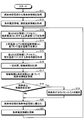
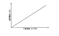
- Diagram showing configuration example of programmable logic controller Flow chart showing an operation example of a programmable logic controller A diagram showing an example of first correspondence information A diagram showing an example of second correspondence information Figure showing an example of rated current information Diagram showing a configuration example of hardware that realizes a control unit
- FIG. 1 is a diagram showing a configuration example of a programmable logic controller (PLC) according to an embodiment of the present invention.
- PLC 100 according to the present embodiment is realized by combining a plurality of units.
- the PLC 100 includes various units such as a base unit 1, a power supply unit 2, a control unit 3, and a controlled unit 4.
- the PLC 100 includes one or more controlled units 4.
- the base unit 1 electrically connects the power supply unit 2, the control unit 3 and the controlled unit 4.
- the power supply unit 2 supplies power to the control unit 3 and the controlled unit 4 via the base unit 1.
- the control unit 3 controls the controlled unit 4.
- the controlled units 4 are various units that operate according to an instruction from the control unit 3.
- the controlled unit 4 corresponds to an input unit for inputting a signal from a sensor or the like attached to a production apparatus or equipment, an output unit for outputting a control signal to an actuator, or a network unit for connecting the PLC 100 to a communication network. .
- the power-supply unit 2 has mounted thereon a lifetime-expected component (not shown), and the power-supply unit 2 itself has a lifetime.
- An example of a lifetime component is an electrolytic capacitor.
- the power supply unit 2 which is a component mounting unit with a limited life, includes a remaining life storage unit 21 that stores remaining life information that is information on the remaining life of the power supply unit 2.
- the remaining life storage unit 21 is realized by a non-volatile memory.
- the remaining life information stored in the remaining life storage unit 21 is updated by the control unit 3.
- the initial value of the remaining life information indicates the life of the power supply unit 2, that is, the remaining life of the power supply unit 2 before the start of use. In the following description, "remaining life” is referred to as "remaining life”.
- the control unit 3 includes a load current calculation unit 31, an estimated temperature calculation unit 32, a remaining life calculation unit 33, an operating time measurement unit 34, a life notification unit 35, and a storage unit 36.
- the load current calculation unit 31, the estimated temperature calculation unit 32, the remaining life calculation unit 33, and the operating time measurement unit 34 constitute a life diagnosis unit 30 that calculates the remaining life of the power supply unit 2.
- the load current calculation unit 31 calculates the load current flowing to the PLC 100.
- the estimated temperature calculation unit 32 calculates the estimated temperature of the serviceable component in operation of the PLC 100 based on the load current of the PLC 100.
- the remaining life calculation unit 33 calculates the remaining life of the power supply unit 2 based on the estimated temperature of the serviceable part during operation of the PLC 100 and the operation time of the PLC 100.
- the operating time measuring unit 34 measures the operating time of the PLC 100.
- the life notification unit 35 When the remaining life of the power supply unit 2 reaches a predetermined length, the life notification unit 35 notifies the user of it.
- the storage unit 36 is information used when each part of the life diagnosis unit 30 calculates the remaining life of the power supply unit 2, specifically, load current information, ambient temperature information, first correspondence information, and second correspondence. Maintain information and rated current information.
- the storage unit 36 obtains these pieces of information in advance from the user via an input device (not shown).
- the input device corresponds to a mouse, a keyboard, a touch panel, and the like.
- the load current information is information on the load current of the PLC 100 in operation of the PLC 100.
- the load current of the PLC 100 may be determined by actually operating the PLC 100 and may be determined by measurement, or the sum of rated currents of the units constituting the PLC 100 may be calculated and used as the load current.
- Ambient temperature information is information on the ambient temperature of the PLC 100 before the PLC 100 operates. Before the PLC 100 operates, current does not flow to each component constituting the PLC 100 and there is no heat generation, so the ambient temperature of the PLC 100 can be regarded as the temperature of the lifetime component. That is, the information on the ambient temperature of the PLC 100 is also information indicating the temperature of the lifespan part before the PLC 100 operates.
- the ambient temperature of the PLC 100 and the temperature of the lifetime component may be different because the standby current flows even if the PLC 100 is not in operation.
- the difference between the ambient temperature of PLC 100 and the temperature of the lifetime component is usually constant. Therefore, when the ambient temperature of the PLC 100 before the operation of the PLC 100 is different from the temperature of the lifetime component, the information on the difference between these temperatures is also held in the storage unit 36.
- temperature control is generally performed so that the temperature is constant. In such a case, the target temperature for temperature control can be the ambient temperature of the PLC 100 before the PLC 100 operates.
- the first correspondence information is information representing the correspondence between the load current of the PLC 100 and the amount of increase in the estimated temperature of the lifetime component.
- the second correspondence information is information representing the correspondence between the estimated temperature of the lifespan part of the PLC 100 and the life factor of the power supply unit 2.
- the life factor of the power supply unit 2 is a factor used in the process of calculating the remaining life of the power supply unit 2 by the remaining life calculation unit 33.
- the life factor of the power supply unit 2 is, for example, the life of each of the components installed in the power supply unit 2 for each temperature and the power supply unit 2 when the power supply unit 2 is used in an environment of a specified ambient temperature It can be expressed by the following equation (1) using the life specification which is the life of.
- the remaining life storage unit 21 may be deleted from the power supply unit 2 and the storage unit 36 of the control unit 3 may be configured to hold the remaining life information of the power supply unit 2.
- a configuration comprising 21 is desirable.
- the power supply unit 2 is configured to include the remaining life storage unit 21 as illustrated in FIG. 1, even if the control unit 3 is replaced, the new control unit 3 after replacement has the remaining life storage unit 21. This is because the remaining life of the power supply unit 2 can be known by using the remaining life information stored in the above. Since the PLC is configured by combining the units required to realize the function required at the production site, the combination of units may be changed according to the change of the production facility. That is, the combination of the control unit and the power supply unit may be changed.
- the power supply unit is not necessarily replaced with a new power supply unit, but may be replaced with a proven power supply unit used in another PLC.
- the control unit may fail and the need to replace the control unit may arise.
- the control unit holds the remaining life information of the power supply unit, if the combination of the control unit and the power supply unit is changed, the remaining life of the power supply unit can not be calculated after the change.
- the power supply unit is configured to include the remaining life storage unit, the remaining life of the power supply unit can be calculated even after the combination of the control unit and the power supply unit is changed.
- FIG. 2 is a flowchart showing an operation example of the PLC 100.
- the control unit 3 performs the operation according to the flowchart shown in FIG.
- the control unit 3 starts the operation shown in FIG. 2 when the power of the PLC 100 is turned on.
- the remaining life calculation unit 33 acquires remaining life information from the remaining life storage unit 21 of the power supply unit 2 (step S11). Further, in the life diagnosis unit 30 of the control unit 3, the estimated temperature calculation unit 32 acquires load current information and ambient temperature information from the storage unit 36 (step S12).
- the estimated temperature calculation unit 32 accesses the first correspondence information held by the storage unit 36, and acquires the temperature rise ( ⁇ T) with respect to the load current (I) (step S13).
- FIG. 3 is a diagram showing an example of the first correspondence information.
- the first correspondence information is information representing the correspondence between the load current and the rising temperature.
- the first correspondence information may be any information as long as the correspondence relation between the load current and the rising temperature can be understood, and may be a mathematical expression.
- the estimated temperature calculation unit 32 obtains the temperature increase ( ⁇ T) corresponding to the load current (I) represented by the load current information acquired in step S12 using the first correspondence information.
- the estimated temperature calculation unit 32 calculates an estimated temperature (T) based on the temperature increase ( ⁇ T) acquired in step S13 and the ambient temperature information acquired in step S12 (step S14). In step S14, the estimated temperature calculation unit 32 adds the rising temperature to the ambient temperature represented by the ambient temperature information to obtain an estimated temperature.
- the estimated temperature is an estimated value of the temperature of a lifetime component of the PLC 100 in a state where the PLC 100 is in operation.
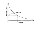
- FIG. 4 is a diagram showing an example of second correspondence information.
- the second correspondence information is information representing the correspondence between the estimated temperature and the life factor.
- the life factor decreases as the estimated temperature rises.
- the life factor in the case where the estimated temperature is equal to the upper temperature limit value of the serviceable part satisfying the life specification of the power supply unit 2 is 1.
- the upper temperature limit value of the serviceable part is the upper temperature limit of the temperature range in which the operation of the serviceable part is guaranteed. For example, the temperature upper limit of the serviceable part in the temperature range of 0 to 30 ° C. The value is 30 ° C.
- the upper temperature limit value of the serviceable part corresponds to the "rated temperature” shown in FIG.
- the second correspondence information may be any information as long as the correspondence between the estimated temperature and the life coefficient can be known, and may be a mathematical expression.
- the remaining life calculation unit 33 obtains a life factor corresponding to the estimated temperature (T) calculated in step S14 using the second correspondence information.
- the operation time measurement unit 34 measures the operation time of the PLC 100 for a certain period of time (step S16).
- the operating time measurement unit 34 measures the operating time of the PLC 100 over a predetermined fixed time, such as 30 minutes or 1 hour, for example.
- the operation time measuring unit 34 monitors whether the operation to operate the PLC 100 is performed while the PLC 100 is stopped, monitors whether the operation to stop the PLC 100 is performed while the PLC 100 is operating, and the operation of the PLC 100 is performed. Measure time That is, the operation time measuring unit 34 starts counting when detecting an operation to operate the PLC 100, and stops counting when detecting an operation to stop the PLC 100.
- the remaining life calculation unit 33 determines in step S11 based on the operation time measured by the operation time measurement unit 34 in step S16 and the life factor acquired in step S15.
- the acquired remaining life information is updated (step S17).
- the remaining life calculation unit 33 calculates the remaining life after updating according to the following equation (2), and updates the remaining life information to a value representing the remaining life after updating.
- (Remaining life after update) (Remaining life before update)-(Operating time) / (Life factor) ... (2)
- the remaining life calculation unit 33 checks whether or not the remaining life represented by the updated remaining life information is equal to or less than a predetermined remaining life setting value which is a threshold (step S18). If the remaining life is not less than the remaining life set value (step S18: No), the remaining life calculation unit 33 writes the updated remaining life information in the remaining life storage unit 21 of the power supply unit 2 (step S20). On the other hand, if the remaining life is less than the remaining life set value (step S18: Yes), the life notifier 35 of the control unit 3 notifies the user that the remaining life of the power supply unit 2 has decreased (step S19).
- the remaining life set value is, for example, a value such that notification to the user is performed when the remaining life of the power supply unit 2 reaches 30 hours.
- the remaining life setting value may be changed by the user. Notification to the user by the lifetime notification unit 35 may be performed by any method.
- the lifetime notification unit 35 may notify the user using a display device such as a display, or may notify the user using a light emitting diode (LED). Notification to the user may be performed by another method.
- the life notification unit 35 executes step S19, the remaining life calculation unit 33 executes step S20.
- the control unit 3 constantly monitors whether an operation to turn off the power of the PLC 100 has been performed.
- the control unit 3 detects that the operation to turn off the power is performed, the control unit 3 stops the control of each controlled unit 4, and the latest remaining life information at that time is stored in the remaining life storage unit of the power supply unit 2.
- the control unit 3 executes the same process as the process of step S20 shown in FIG.
- the remaining life information held by the remaining life storage unit 21 of the power supply unit 2 is updated also when an operation to turn off the power of the PLC 100 is performed. Therefore, the process of step S20 shown in FIG.
- step S20 can be omitted.
- the operation of PLC 100 may stop without an operation to turn off the power due to a power failure or the like, and therefore, the components including the processing of step S20 provide a lifespan part. It is possible to improve the estimation accuracy of the unit replacement time.
- step S21 the load current calculation unit 31 updates the load current information.
- step S21 the load current calculation unit 31 confirms whether or not there is a change in the load current of the PLC 100, and when there is a change, updates the load current information.
- the load current calculation unit 31 passes the updated load current information to the estimated temperature calculation unit 32 when the load current information is updated.
- step S21 the reason for performing step S21 will be described.
- the configuration of the PLC 100 is changed during operation, specifically, the controlled unit 4 attached to the base unit 1 is removed, or the controlled unit 4 is newly attached to the base unit 1 There is.
- the controlled unit 4 attached to the base unit 1 may stop operating due to failure or the like.
- the load current also changes. Therefore, the load current calculation unit 31 confirms whether the configuration of the PLC 100 has changed, and updates the load current information when a change in the configuration is detected. By updating the load current information in accordance with changes in the configuration of the PLC 100, it is possible to improve the calculation accuracy of the remaining life, and to notify the user of an appropriate replacement time of the power supply unit 2.
- the load current calculation unit 31 transmits a control signal for confirming the presence of each of the controlled units 4 to confirm whether the configuration of the PLC 100 has changed. Specifically, the load current calculation unit 31 transmits a control signal for confirming the presence of the controlled unit 4, and each controlled unit 4 that has received the control signal transmits a response signal.
- the response signal includes identification information of each controlled unit 4 of the transmission source. The load current calculation unit 31 determines that the controlled unit 4 that is the transmission source of the received response signal is attached to the base unit 1 and is operating.
- the load current calculation unit 31 calculates updated load current information based on the confirmation result. Specifically, the load current calculation unit 31 calculates a total value of the rated current of the controlled unit 4 in operation, the rated current of the power supply unit 2 and the rated current of the control unit 3, Do.
- the rated current of the operated controlled unit 4, the power supply unit 2 and the control unit 3 can be known from the rated current information held by the storage unit 36.
- FIG. 5 is a diagram showing an example of the rated current information held by the storage unit 36. As shown in FIG.
- the rated current information includes identification information such as a unit name and a rated current value.
- the rated current information includes identification information and rated current values of all units attachable to the base unit 1 of the PLC 100, that is, the power supply unit 2, the control unit 3, and the controlled unit 4.
- the load current calculation unit 31 may not calculate the updated load current information. Further, the load current calculation unit 31 may write the updated load current information in the storage unit 36. Further, the transmission of the control signal for confirming the configuration of the PLC 100, that is, the transmission of the control signal for confirming the presence of each of the controlled units 4 may be performed by other than the load current calculating unit 31. Further, the process of the control unit 3 transmitting the control signal for confirming the configuration of the PLC 100 and receiving the response signal is not performed after the execution of step S20 but while the processes of steps S13 to S20 are being performed. It may be performed at any timing of For example, the control unit 3 may transmit a control signal for confirming the presence of each of the controlled units 4 at regular intervals.
- FIG. 6 is a diagram showing a configuration example of hardware that realizes the control unit 3.
- the load current calculation unit 31, the estimated temperature calculation unit 32, the remaining life calculation unit 33, the operating time measurement unit 34, and the life notification unit 35 of the control unit 3 can be realized by the processor 101 and the memory 102 shown in FIG. It is.
- a program for operating as the load current calculation unit 31, the estimated temperature calculation unit 32, the remaining life calculation unit 33, the operating time measurement unit 34, and the life notification unit 35 is stored in the memory 102.
- each of these components can be realized.
- the processor 101 is a processing circuit such as a central processing unit (CPU) (central processing unit, processing unit, processing unit, arithmetic unit, microprocessor, microcomputer, processor, also referred to as DSP (digital signal processor)), system LSI (Large Scale Integration) .
- the memory 102 is a non-volatile or volatile semiconductor memory such as a random access memory (RAM), a read only memory (ROM), a flash memory, an erasable programmable read only memory (EPROM), and an electrically erasable programmable read only memory (EEPROM). , Magnetic disks, optical disks, etc.
- the control unit 3 calculates the estimated temperature of the serviceable part of the PLC 100 in the operating state of the PLC 100 based on the load current information and the ambient temperature information, The remaining life of the power supply unit 2 is calculated based on the life factor corresponding to the estimated temperature of the end-of-life component and the operation time of the PLC 100. Thereby, it is possible to calculate the replacement time of the power supply unit 2 while preventing the cost of the PLC 100 from increasing. Further, since power supply unit 2 holds the remaining life information of its own unit, even if control unit 3 used in combination with power supply unit 2 is changed, power supply unit 2 is changed in PLC 100 after the combination is changed. The exchange time of can be calculated.
- the service life parts are mounted only on the power supply unit 2, but the service life parts are for part or all of the controlled unit 4. It may be installed. That is, there may be a case where the PLC 100 includes a plurality of lifetime component mounting units. In that case, the controlled unit 4 corresponding to the lifespan part mounting unit includes a remaining life storage unit that stores remaining life information as the power supply unit 2 does.
- the storage unit 36 of the control unit 3 holds the above-described first correspondence information and second correspondence information for each of the plurality of lifetime component mounting units.
- the life diagnosis unit 30 uses the first correspondence information and the second correspondence information that are associated with each of the service life parts mounting units when calculating the remaining life of the service life parts mounting units.
- control unit 3 includes the life notification unit 35
- the power supply unit 2 or the controlled unit 4 may include the life notification unit.
- the storage unit 36 holds load current information in advance and uses load current information to calculate the estimated temperature of a lifetime component of the PLC 100, it has a unit for measuring the load current.
- the estimated temperature of the serviceable part of the PLC 100 may be calculated using the measured load current value, and the remaining life of the power supply unit 2 may be calculated based on the calculated estimated temperature.
- the control unit 3 of the PLC 100 stores information for estimating the ambient temperature in the storage unit 36 instead of the above-described ambient temperature information.
- information for estimating the ambient temperature for example, it is a graph showing a change in temperature (a change in ambient temperature) of one day.
- the control unit 3 uses the obtained estimated value in place of the ambient temperature indicated by the ambient temperature information described above to calculate the estimated temperature of the lifespan part. That is, in step S12 shown in FIG. 2, the control unit 3 acquires load current information and information for estimating the ambient temperature, which is a graph representing the temperature change per day, and changes the temperature change per day An estimate of the ambient temperature is obtained based on the representing graph and time information. Then, at step S14 shown in FIG. 2, the control unit 3 calculates the estimated temperature T based on the temperature increase ⁇ T and the estimated value of the ambient temperature.
- control unit 3 since the ambient temperature changes with the passage of time, the control unit 3 performs processing for acquiring an estimated value of the ambient temperature based on a graph representing temperature change per day and time information, for example, every 10 minutes As it passes, it repeats and updates the estimate of the ambient temperature.
- the graph representing the daily temperature change described above may be a correspondence table of time and ambient temperature.
- the control unit 3 may, for example, display 12 types of "graphs representing the change in temperature per day” corresponding to each month from January to December or "correspondence table of time and ambient temperature May be stored in the storage unit 36, and 12 types of graphs or correspondence tables may be used properly.
- the control unit 3 stores one type of “graph representing temperature change per day” or “correspondence table of time and ambient temperature” in the storage unit 36 and corrects this based on the date and time, and then the ambient temperature An estimated value of may be acquired.
- the control unit 3 may correct the estimated value of the ambient temperature based on the weather information.
- the control unit 3 corrects the estimated value of the ambient temperature obtained from the current time and the graph to a large value, and in the case of "rain”, reduces the estimated value of the ambient temperature to a small value. to correct.
- the control unit 3 acquires weather information from the outside via the communication network whose description is omitted in FIG.
- the control unit 3 may acquire information of an expected temperature for each time in addition to the weather information.
- the configuration shown in the above embodiment shows an example of the contents of the present invention, and can be combined with another known technique, and one of the configurations is possible within the scope of the present invention. Parts can be omitted or changed.
- Reference Signs List 1 base unit, 2 power supply unit, 3 control unit, 4 controlled unit, 21 remaining life storage unit, 30 life diagnosis unit, 31 load current calculation unit, 32 estimated temperature calculation unit, 33 remaining life calculation unit, 34 operation time measurement Part, 35 Life Informing Part, 36 Storage Part, 100 Programmable Logic Controller (PLC).
- PLC Programmable Logic Controller
Landscapes
- Engineering & Computer Science (AREA)
- Physics & Mathematics (AREA)
- General Physics & Mathematics (AREA)
- Automation & Control Theory (AREA)
- Manufacturing & Machinery (AREA)
- Human Computer Interaction (AREA)
- Geometry (AREA)
- General Engineering & Computer Science (AREA)
- Quality & Reliability (AREA)
- Programmable Controllers (AREA)
Abstract
Description
図1は、本発明の実施の形態にかかるプログラマブルロジックコントローラ(PLC)の構成例を示す図である。本実施の形態にかかるPLC100は、複数のユニットを組み合わせて実現される。具体的には、PLC100は、ベースユニット1、電源ユニット2、制御ユニット3および被制御ユニット4といった各種ユニットで構成される。なお、PLC100は、被制御ユニット4を1台以上備える。 Embodiment.
FIG. 1 is a diagram showing a configuration example of a programmable logic controller (PLC) according to an embodiment of the present invention.
(寿命係数)=(有寿命部品の温度ごとの寿命)/(寿命仕様) …(1) The load current information is information on the load current of the
(Life factor) = (Life according to temperature of the serviceable part) / (Life specification) ... (1)
(更新後の残寿命)=(更新前の残寿命)-(稼働時間)/(寿命係数) …(2) Next, in the
(Remaining life after update) = (Remaining life before update)-(Operating time) / (Life factor) ... (2)
Claims (8)
- 制御ユニットと、有寿命部品が搭載された有寿命部品搭載ユニットとを含んで構成されたプログラマブルロジックコントローラであって、
前記有寿命部品搭載ユニットは、
前記有寿命部品搭載ユニットの残寿命を表す残寿命情報を保持する残寿命記憶部、
を備え、
前記制御ユニットは、
前記プログラマブルロジックコントローラの負荷電流を算出する負荷電流算出部と、
ユーザから取得した周囲温度情報と、前記負荷電流とに基づいて、前記プログラマブルロジックコントローラが稼働中の有寿命部品の温度の推定値を算出する推定温度算出部と、
前記プログラマブルロジックコントローラの稼働時間と前記推定値とに基づいて、前記残寿命情報を更新する残寿命算出部と、
を備えることを特徴とするプログラマブルロジックコントローラ。 A programmable logic controller configured to include a control unit and a lifespan component mounting unit mounted with a lifespan component,
The said lifetime component mounting unit is
A remaining life storage unit that holds remaining life information representing the remaining life of the above-described part loading unit,
Equipped with
The control unit
A load current calculation unit that calculates a load current of the programmable logic controller;
An estimated temperature calculation unit that calculates an estimated value of the temperature of the serviceable component being operated by the programmable logic controller based on the ambient temperature information acquired from the user and the load current;
A remaining life calculation unit that updates the remaining life information based on the operation time of the programmable logic controller and the estimated value;
A programmable logic controller comprising: - 前記有寿命部品搭載ユニットの残寿命がしきい値以下となった場合にその旨をユーザに報知する寿命報知部、
を備えることを特徴とする請求項1に記載のプログラマブルロジックコントローラ。 A life notification unit for notifying the user of the fact that the remaining life of the component mounting unit with the life becomes equal to or less than a threshold value,
The programmable logic controller according to claim 1, comprising: - 前記有寿命部品搭載ユニットを電源ユニットとする、
ことを特徴とする請求項1または2に記載のプログラマブルロジックコントローラ。 Using the above-mentioned component mounting unit with a lifetime as a power supply unit,
The programmable logic controller according to claim 1 or 2, characterized in that: - 前記負荷電流算出部は、前記プログラマブルロジックコントローラを構成している各ユニットの定格電流値の合計値を算出して前記負荷電流とする、
ことを特徴とする請求項1から3のいずれか一つに記載のプログラマブルロジックコントローラ。 The load current calculation unit calculates a total value of rated current values of respective units constituting the programmable logic controller, and sets it as the load current.
The programmable logic controller according to any one of claims 1 to 3, characterized in that. - 前記残寿命算出部は、前記推定値から導き出される寿命係数を前記稼働時間に乗算して得られた時間を前記残寿命から減算し、減算結果を表す情報を更新後の前記残寿命情報とする、
ことを特徴とする請求項1から4のいずれか一つに記載のプログラマブルロジックコントローラ。 The remaining life calculation unit subtracts the time obtained by multiplying the operating time by the life factor derived from the estimated value from the remaining life, and uses information representing the result of subtraction as the updated remaining life information. ,
The programmable logic controller according to any one of claims 1 to 4, characterized in that: - 前記有寿命部品搭載ユニットを複数含み、
前記残寿命算出部は、複数の前記有寿命部品搭載ユニットの各々について前記寿命係数を求め、前記有寿命部品搭載ユニットの各々の残寿命情報を、前記有寿命部品搭載ユニットの各々に対応する前記寿命係数を用いて算出する、
ことを特徴とする請求項5に記載のプログラマブルロジックコントローラ。 Including a plurality of the above-mentioned component mounting units,
The remaining life calculation unit obtains the life factor for each of the plurality of lifetime component mounting units, and the remaining lifetime information of each lifetime component mounting unit corresponds to each of the lifetime component mounting units. Calculated using the life factor,
The programmable logic controller according to claim 5, characterized in that: - 制御ユニットと、有寿命部品が搭載された有寿命部品搭載ユニットとを含んで構成されたプログラマブルロジックコントローラの前記制御ユニットであって、
前記プログラマブルロジックコントローラの負荷電流を算出する負荷電流算出部と、
ユーザから取得した周囲温度情報と、前記負荷電流とに基づいて、前記プログラマブルロジックコントローラが稼働中の有寿命部品の温度の推定値を算出する推定温度算出部と、
前記プログラマブルロジックコントローラの稼働時間と前記推定値とに基づいて、前記有寿命部品搭載ユニットの残寿命を算出する残寿命算出部と、
を備えることを特徴とする制御ユニット。 A control unit for a programmable logic controller, comprising: a control unit; and a long-lived component mounting unit on which a long-lived component is mounted,
A load current calculation unit that calculates a load current of the programmable logic controller;
An estimated temperature calculation unit that calculates an estimated value of the temperature of the serviceable component being operated by the programmable logic controller based on the ambient temperature information acquired from the user and the load current;
A remaining life calculating unit that calculates a remaining life of the component mounting unit with a life based on the operation time of the programmable logic controller and the estimated value;
A control unit comprising: - 制御ユニットと、有寿命部品が搭載された有寿命部品搭載ユニットとを含んで構成されたプログラマブルロジックコントローラにおいて、前記有寿命部品搭載ユニットの残寿命を算出する方法であって、
前記制御ユニットが、前記プログラマブルロジックコントローラの負荷電流を算出するステップと、
前記制御ユニットが、ユーザから取得した周囲温度情報と、前記負荷電流とに基づいて、前記プログラマブルロジックコントローラが稼働中の有寿命部品の温度の推定値を算出するステップと、
前記制御ユニットが、前記プログラマブルロジックコントローラの稼働時間と前記推定値とに基づいて、前記有寿命部品搭載ユニットの残寿命を算出するステップと、
を含むことを特徴とするユニットの寿命算出方法。 What is claimed is: 1. A programmable logic controller comprising a control unit and a long-lived component mounting unit having long-lived components mounted thereon, wherein the remaining life of the long-lived component mounting unit is calculated,
The control unit calculating a load current of the programmable logic controller;
The control unit calculates an estimated value of the temperature of the serviceable component under operation of the programmable logic controller based on the ambient temperature information acquired from the user and the load current;
Calculating, by the control unit, the remaining life of the lifetime component mounting unit based on the operation time of the programmable logic controller and the estimated value;
A method of calculating the life of a unit comprising:
Priority Applications (6)
| Application Number | Priority Date | Filing Date | Title |
|---|---|---|---|
| CN201780026313.6A CN109526233A (en) | 2017-07-18 | 2017-07-18 | The Life Calculating Methods of programmable logic controller (PLC), control unit and unit |
| US16/092,354 US20190384251A1 (en) | 2017-07-18 | 2017-07-18 | Programmable logic controller, method of calculating life of unit, and limited-life-component-equipped unit |
| DE112017001308.9T DE112017001308T5 (en) | 2017-07-18 | 2017-07-18 | Programmable logic controller, control unit and method for calculating the life of a unit |
| JP2018511772A JP6338804B1 (en) | 2017-07-18 | 2017-07-18 | Programmable logic controller, unit life calculation method, and component-equipped unit |
| KR1020187030795A KR102004115B1 (en) | 2017-07-18 | 2017-07-18 | Programmable Logic Controller, Unit Lifetime Calculation Method, and Timed Lifetime |
| PCT/JP2017/025933 WO2019016858A1 (en) | 2017-07-18 | 2017-07-18 | Programmable logic controller, control unit, and method for calculating lifespan of unit |
Applications Claiming Priority (1)
| Application Number | Priority Date | Filing Date | Title |
|---|---|---|---|
| PCT/JP2017/025933 WO2019016858A1 (en) | 2017-07-18 | 2017-07-18 | Programmable logic controller, control unit, and method for calculating lifespan of unit |
Publications (1)
| Publication Number | Publication Date |
|---|---|
| WO2019016858A1 true WO2019016858A1 (en) | 2019-01-24 |
Family
ID=62487365
Family Applications (1)
| Application Number | Title | Priority Date | Filing Date |
|---|---|---|---|
| PCT/JP2017/025933 WO2019016858A1 (en) | 2017-07-18 | 2017-07-18 | Programmable logic controller, control unit, and method for calculating lifespan of unit |
Country Status (6)
| Country | Link |
|---|---|
| US (1) | US20190384251A1 (en) |
| JP (1) | JP6338804B1 (en) |
| KR (1) | KR102004115B1 (en) |
| CN (1) | CN109526233A (en) |
| DE (1) | DE112017001308T5 (en) |
| WO (1) | WO2019016858A1 (en) |
Citations (6)
| Publication number | Priority date | Publication date | Assignee | Title |
|---|---|---|---|---|
| JPH01216270A (en) * | 1988-02-24 | 1989-08-30 | Mitsubishi Electric Corp | Detecting device for power source service life |
| JPH01255003A (en) * | 1988-04-05 | 1989-10-11 | Mitsubishi Electric Corp | Programmable controller |
| JPH11175112A (en) * | 1997-12-05 | 1999-07-02 | Mitsubishi Electric Corp | Preventive maintenance device for equipment for programmable controller |
| JP2006294007A (en) * | 2005-03-15 | 2006-10-26 | Omron Corp | Programmable controller device |
| JP2011119428A (en) * | 2009-12-03 | 2011-06-16 | Fuji Electric Systems Co Ltd | Remaining life estimation method, and remaining life estimation system |
| JP2013080787A (en) * | 2011-10-03 | 2013-05-02 | Fuji Electric Co Ltd | Life estimation device, life estimation method and program |
Family Cites Families (19)
| Publication number | Priority date | Publication date | Assignee | Title |
|---|---|---|---|---|
| JP4490577B2 (en) * | 2000-10-02 | 2010-06-30 | 株式会社キーエンス | PLC system construction support tool |
| JP3850311B2 (en) * | 2002-02-21 | 2006-11-29 | オムロン株式会社 | Remaining life prediction notification method and electronic device |
| JP2006268834A (en) * | 2005-02-28 | 2006-10-05 | Omron Corp | Tool device for plc |
| EP1703347B1 (en) * | 2005-03-15 | 2018-10-17 | Omron Corporation | Programmable logic controller device and programmable logic controller system |
| JP4349408B2 (en) * | 2005-12-28 | 2009-10-21 | 日本電気株式会社 | Life prediction monitoring apparatus, life prediction monitoring method, and life prediction monitoring program |
| JP4749190B2 (en) * | 2006-03-24 | 2011-08-17 | 三洋電機株式会社 | Welding detection method for discriminating welding of power supply device for vehicle and contactor of this power supply device |
| US20080284449A1 (en) * | 2007-05-15 | 2008-11-20 | Vijay Phadke | Power converters with component stress monitoring for fault prediction |
| US7719812B2 (en) * | 2007-05-15 | 2010-05-18 | Astec International Limited | Power converters with rate of change monitoring for fault prediction and/or detection |
| US7830269B2 (en) * | 2007-09-14 | 2010-11-09 | Astec International Limited | Health monitoring for power converter capacitors |
| FR2923020B1 (en) * | 2007-10-30 | 2009-11-13 | Mge Ups Systems | METHOD AND DEVICE FOR PREDICTING ELECTROLYTIC CAPACITOR FAILURES, CONVERTER AND NON-INTERRUPTION POWER EQUIPPED WITH SUCH A DEVICE |
| EP2290383A4 (en) * | 2008-06-06 | 2014-10-22 | Meidensha Electric Mfg Co Ltd | Capacitor's remaining lifetime diagnosing device, and electric power compensating device having the remaining lifetime diagnosing device |
| US7822578B2 (en) * | 2008-06-17 | 2010-10-26 | General Electric Company | Systems and methods for predicting maintenance of intelligent electronic devices |
| WO2010057364A1 (en) * | 2008-11-20 | 2010-05-27 | The University Of Hong Kong | Apparatus for estimating the remaining life of a power converter and its method |
| WO2011125213A1 (en) * | 2010-04-09 | 2011-10-13 | トヨタ自動車株式会社 | Secondary battery degradation determination device and degradation determination method |
| JP5514010B2 (en) * | 2010-06-25 | 2014-06-04 | 株式会社日立製作所 | Power converter and temperature rise calculation method thereof |
| JP5197897B1 (en) * | 2012-06-05 | 2013-05-15 | 三菱電機株式会社 | Electric motor control device |
| KR20160141971A (en) * | 2015-06-02 | 2016-12-12 | 엘에스산전 주식회사 | Plc apparatus |
| JP2017058146A (en) * | 2015-09-14 | 2017-03-23 | 三菱電機株式会社 | Life estimation circuit and semiconductor device using the same |
| US9869722B1 (en) * | 2016-09-22 | 2018-01-16 | Rockwell Automation Technologies, Inc. | Method and apparatus for electrical component life estimation |
-
2017
- 2017-07-18 WO PCT/JP2017/025933 patent/WO2019016858A1/en active Application Filing
- 2017-07-18 CN CN201780026313.6A patent/CN109526233A/en active Pending
- 2017-07-18 JP JP2018511772A patent/JP6338804B1/en active Active
- 2017-07-18 KR KR1020187030795A patent/KR102004115B1/en active IP Right Grant
- 2017-07-18 US US16/092,354 patent/US20190384251A1/en not_active Abandoned
- 2017-07-18 DE DE112017001308.9T patent/DE112017001308T5/en not_active Withdrawn
Patent Citations (6)
| Publication number | Priority date | Publication date | Assignee | Title |
|---|---|---|---|---|
| JPH01216270A (en) * | 1988-02-24 | 1989-08-30 | Mitsubishi Electric Corp | Detecting device for power source service life |
| JPH01255003A (en) * | 1988-04-05 | 1989-10-11 | Mitsubishi Electric Corp | Programmable controller |
| JPH11175112A (en) * | 1997-12-05 | 1999-07-02 | Mitsubishi Electric Corp | Preventive maintenance device for equipment for programmable controller |
| JP2006294007A (en) * | 2005-03-15 | 2006-10-26 | Omron Corp | Programmable controller device |
| JP2011119428A (en) * | 2009-12-03 | 2011-06-16 | Fuji Electric Systems Co Ltd | Remaining life estimation method, and remaining life estimation system |
| JP2013080787A (en) * | 2011-10-03 | 2013-05-02 | Fuji Electric Co Ltd | Life estimation device, life estimation method and program |
Also Published As
| Publication number | Publication date |
|---|---|
| KR20190009738A (en) | 2019-01-29 |
| JP6338804B1 (en) | 2018-06-06 |
| CN109526233A (en) | 2019-03-26 |
| US20190384251A1 (en) | 2019-12-19 |
| JPWO2019016858A1 (en) | 2019-07-25 |
| DE112017001308T5 (en) | 2019-03-14 |
| KR102004115B1 (en) | 2019-07-25 |
Similar Documents
| Publication | Publication Date | Title |
|---|---|---|
| JP6017787B2 (en) | Power supply for gas discharge lamps | |
| WO2014012367A1 (en) | Online monitoring method and system for power source life and power source | |
| JP2016095610A (en) | Failure warning system and failure warning method | |
| WO2019016858A1 (en) | Programmable logic controller, control unit, and method for calculating lifespan of unit | |
| JP5853204B2 (en) | Lighting control system | |
| JP2015041315A (en) | Control device and control method | |
| CN109716071B (en) | System and method for measuring environmental parameters | |
| WO2015115137A1 (en) | Monitoring device, monitoring system, monitoring method, correction information creation device, correction information creation method, and program | |
| JP2019020830A (en) | Consumption estimation device of lp gas and consumption estimation method | |
| WO2015182217A1 (en) | Monitoring system, monitoring device, server, method for operating monitoring device, method for operating server, and program | |
| JP5355737B2 (en) | Programmable controller | |
| JP6628810B2 (en) | Control device, work support method, and program | |
| US20190012846A1 (en) | Method for determining a mean time to failure of an electrical device | |
| JP6373522B1 (en) | LED lighting evaluation system | |
| JP3466172B2 (en) | Power management unit | |
| JP2013078172A (en) | Digital protection control device | |
| KR20160141971A (en) | Plc apparatus | |
| JP7158318B2 (en) | Lifespan management device, program and lifespan management method | |
| JP2016146033A (en) | Failure prediction electronic device and failure prediction method | |
| JP7292550B1 (en) | Analog current output device, FA system, disconnection prediction device, disconnection prediction method and program | |
| JP2014081881A (en) | Electric energy monitoring device | |
| WO2018091279A1 (en) | Energy measurement for a lighting system | |
| JPWO2019012611A1 (en) | Processing unit | |
| WO2024085234A1 (en) | Charging control device, power storage system, method for reporting remaining charging time, and program for reporting remaining charging time | |
| JP2018019530A (en) | Processor, electric power management device, and ems server |
Legal Events
| Date | Code | Title | Description |
|---|---|---|---|
| ENP | Entry into the national phase |
Ref document number: 2018511772 Country of ref document: JP Kind code of ref document: A |
|
| ENP | Entry into the national phase |
Ref document number: 20187030795 Country of ref document: KR Kind code of ref document: A |
|
| 121 | Ep: the epo has been informed by wipo that ep was designated in this application |
Ref document number: 17918017 Country of ref document: EP Kind code of ref document: A1 |
|
| 122 | Ep: pct application non-entry in european phase |
Ref document number: 17918017 Country of ref document: EP Kind code of ref document: A1 |