WO2019013263A1 - Cutting insert, cutting tool, and method for manufacturing cut workpiece - Google Patents
Cutting insert, cutting tool, and method for manufacturing cut workpiece Download PDFInfo
- Publication number
- WO2019013263A1 WO2019013263A1 PCT/JP2018/026220 JP2018026220W WO2019013263A1 WO 2019013263 A1 WO2019013263 A1 WO 2019013263A1 JP 2018026220 W JP2018026220 W JP 2018026220W WO 2019013263 A1 WO2019013263 A1 WO 2019013263A1
- Authority
- WO
- WIPO (PCT)
- Prior art keywords
- hole
- insert
- recess
- straight line
- cutting
- Prior art date
Links
Images


Classifications
-
- B—PERFORMING OPERATIONS; TRANSPORTING
- B23—MACHINE TOOLS; METAL-WORKING NOT OTHERWISE PROVIDED FOR
- B23B—TURNING; BORING
- B23B27/00—Tools for turning or boring machines; Tools of a similar kind in general; Accessories therefor
- B23B27/007—Tools for turning or boring machines; Tools of a similar kind in general; Accessories therefor for internal turning
-
- B—PERFORMING OPERATIONS; TRANSPORTING
- B23—MACHINE TOOLS; METAL-WORKING NOT OTHERWISE PROVIDED FOR
- B23B—TURNING; BORING
- B23B27/00—Tools for turning or boring machines; Tools of a similar kind in general; Accessories therefor
- B23B27/14—Cutting tools of which the bits or tips or cutting inserts are of special material
- B23B27/16—Cutting tools of which the bits or tips or cutting inserts are of special material with exchangeable cutting bits or cutting inserts, e.g. able to be clamped
- B23B27/1603—Cutting tools of which the bits or tips or cutting inserts are of special material with exchangeable cutting bits or cutting inserts, e.g. able to be clamped with specially shaped plate-like exchangeable cutting inserts, e.g. chip-breaking groove
- B23B27/1611—Cutting tools of which the bits or tips or cutting inserts are of special material with exchangeable cutting bits or cutting inserts, e.g. able to be clamped with specially shaped plate-like exchangeable cutting inserts, e.g. chip-breaking groove characterised by having a special shape
-
- B—PERFORMING OPERATIONS; TRANSPORTING
- B23—MACHINE TOOLS; METAL-WORKING NOT OTHERWISE PROVIDED FOR
- B23B—TURNING; BORING
- B23B1/00—Methods for turning or working essentially requiring the use of turning-machines; Use of auxiliary equipment in connection with such methods
-
- B—PERFORMING OPERATIONS; TRANSPORTING
- B23—MACHINE TOOLS; METAL-WORKING NOT OTHERWISE PROVIDED FOR
- B23B—TURNING; BORING
- B23B27/00—Tools for turning or boring machines; Tools of a similar kind in general; Accessories therefor
- B23B27/04—Cutting-off tools
-
- B—PERFORMING OPERATIONS; TRANSPORTING
- B23—MACHINE TOOLS; METAL-WORKING NOT OTHERWISE PROVIDED FOR
- B23B—TURNING; BORING
- B23B29/00—Holders for non-rotary cutting tools; Boring bars or boring heads; Accessories for tool holders
- B23B29/04—Tool holders for a single cutting tool
- B23B29/043—Tool holders for a single cutting tool with cutting-off, grooving or profile cutting tools, i.e. blade- or disc-like main cutting parts
-
- B—PERFORMING OPERATIONS; TRANSPORTING
- B23—MACHINE TOOLS; METAL-WORKING NOT OTHERWISE PROVIDED FOR
- B23B—TURNING; BORING
- B23B2220/00—Details of turning, boring or drilling processes
- B23B2220/12—Grooving
- B23B2220/123—Producing internal grooves
-
- B—PERFORMING OPERATIONS; TRANSPORTING
- B23—MACHINE TOOLS; METAL-WORKING NOT OTHERWISE PROVIDED FOR
- B23B—TURNING; BORING
- B23B2220/00—Details of turning, boring or drilling processes
- B23B2220/12—Grooving
- B23B2220/126—Producing ring grooves
Definitions
- the present aspect generally relates to a cutting insert, a cutting tool, and a method of manufacturing a machined product. More specifically, the present invention relates to a cutting tool used for grooving.
- Patent Document 1 As a cutting tool used when cutting a work material, for example, a cutting tool described in Japanese Patent Application Publication No. 2014-504561 (Patent Document 1) is known.
- the insert in the cutting tool described in Patent Document 1 has a recess located on the upper surface side.
- the holder in the cutting tool of patent document 1 has the convex part corresponding to said recessed part.
- One insert of the aspect has a first surface, a second surface located on the opposite side of the first surface, a side surface located between the first surface and the second surface, and a first one of the side surfaces.
- a main body having a first cutting edge located at least a part of a ridge line where a side surface and a second side surface adjacent to the first side intersect and a through hole opening at the first surface and the second surface There is.
- the body further includes a first recess extending from the first surface to the side surface. The first recess is located apart from a virtual straight line connecting the first cutting edge and the center of the through hole when the first surface is viewed from the front.
- FIG. 3 is a cross-sectional view showing a cross section II in FIG. 2; It is the side view which looked at the cutting insert shown in FIG. 3 from the D direction.
- FIG. 3 is a cross-sectional view showing a II-II cross section in FIG. 2; It is a top view of the modification of the cutting insert shown in FIG. 11 is a cross-sectional view showing a III-III cross section in FIG. 11 is a cross-sectional view showing a IV-IV cross section in FIG.
- FIG. 24 is an enlarged view of a part of the side of the first end of the holder shown in FIG. 23; It is the top view which looked at the holder shown in FIG. 23 toward the 1st end.
- 26 is a cross-sectional view showing a IV-IV cross section in FIG. 25. It is the figure which showed 1 process in the manufacturing method of the cutting material of embodiment. It is the figure which showed 1 process in the manufacturing method of the cutting material of embodiment. It is the figure which showed 1 process in the manufacturing method of the cutting material of embodiment.
- cutting inserts 1 (hereinafter, also simply referred to as inserts 1) according to a plurality of embodiments will be described in detail with reference to the drawings.
- the drawings referred to in the following simply show only the main members necessary for describing each embodiment.
- the insert 1 of the present disclosure may comprise any component not shown in the figures to which it refers.
- the dimensions of the members in the respective drawings do not faithfully represent the dimensions of the actual constituent members, the dimensional ratio of the respective members, and the like.
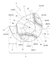
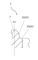
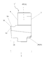
- One insert 1 of the embodiment has a flat plate-shaped main body 3 as shown in FIG.
- the main body 3 has a first surface 7, a second surface 9 located on the opposite side of the first surface 7, and a side surface 11 located between the first surface 7 and the second surface 9.
- the first surface 7 and the second surface 9 may be parallel to each other.
- the side surface 11 has a first side surface 13 and a second side surface 15 adjacent to the first side surface 13 as shown in FIGS. 1 and 2.
- the first side 13 and the second side 15 may intersect.
- the main body 3 may have a first cutting edge 17 located at at least a part of a ridge line where the first side surface 13 and the second side surface 15 intersect.
- the first side surface 13 in the example shown in FIG. 2 extends from the first cutting edge 17 and has a concave shape.
- the second side surface 15 in the example shown in FIG. 2 extends from the first cutting edge 17 and has a planar shape.
- the first side surface 13 may have a rake surface area 13a as shown in FIG.
- the second side surface 15 may have a flank surface area 15a.
- the rake surface area 13a is an area that can contact chips and cause the chips to curl during cutting.
- the rake surface area 13 a is located on a portion of the first side surface 13 along the first cutting edge 17.
- the flank surface area 15a is an area which is escaped so as to reduce the contact with the finished surface of the work material at the time of cutting.
- the flank surface area 15 a is located on a portion of the second side surface 15 along the first cutting edge 17.
- the flank surface area 15a is not required to be in no contact with the finished surface at the time of cutting.
- the first cutting edge 17 may be located at only a part of the ridge line where the first side surface 13 and the second side surface 15 intersect, or may be located at the whole.
- a so-called honing process may be applied to the first cutting edge 17 located at a ridge line where the first side surface 13 and the second side surface 15 intersect. That is, the ridgeline which the 1st side 13 and the 2nd side 15 cross may not be a strict line shape by two sides crossing.
- the main body 3 has a through hole 19 opened at the first surface 7 and the second surface 9 as shown in FIG.
- the insert 1 in the example shown in FIG. 1 and the like has a cutting portion 5 constituted by a first side surface 13, a second side surface 15 and a first cutting edge 17.
- the cutting portion 5 may protrude in a direction away from the central axis P1 of the through hole 19. Therefore, the first cutting edge 17 may be located farthest from the central axis P1 of the through hole 19.
- the through hole 19 may be used as an insertion hole of the fixture when mounting the insert 1 to the holder.
- fasteners include screws, wedges and brazes.
- the main body 3 may have a flat plate shape as described above, and the outer diameters of the first surface 7 and the second surface 9 may be larger than the thickness of the main body 3.
- FIG. 1 is an example, and the shape of the main body 3 is not limited to the shape shown in FIG.
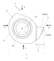
- the main body 3 of the embodiment has a first recess 21 extending from the first surface 7 to the side surface 11.
- the first recess 21 when the first surface 7 is viewed from the front, the first recess 21 is located apart from the virtual straight line L1.
- the virtual straight line L1 connects the first cutting edge 17 and the central axis P1 of the through hole 19.
- the central axis P1 may be orthogonal to the first surface 7 and the second surface 9. In this case, when the first surface 7 is viewed from the front as shown in FIG. 2, the central axis P1 is indicated by a point.
- the virtual straight line L1 is located in a region where load is likely to be applied during cutting.
- the first recess 21 is located apart from the virtual straight line L1 connecting the first cutting edge 17 and the central axis P1 of the through hole 19, the thickness of the main body 3 in the region where load is likely to be applied during cutting Is easy to secure. Therefore, the durability of the insert 1 is high while the insert 1 is stably fixed to the holder by the first recess 21.
- the first side surface 13 may have a rake surface area 13a
- the second side surface 15 may have a flank surface area 15a.
- the first recess 21 is located not on the side of the first side 13 (upper side in FIG. 2) but on the side of the second side 15 (lower side in FIG. 2) with respect to the imaginary straight line L1. doing.
- the first recess 21 may be in contact with or separated from the through hole 19, but as in the example shown in FIG. 2, the first recess 21 may be separated from the through hole 19. Since the insert 1 is fixed to the holder by the fixing tool, a load is easily applied around the through hole 19 in the main body 3. When the first recess 21 is separated from the through hole 19, the thickness around the through hole 19 to which load is easily applied is secured. Therefore, the occurrence of a crack around the through hole 19 is suppressed.
- the first recess 21 may have a first bottom surface 23 and a first wall surface 25 located between the first bottom surface 23 and the first surface 7.
- the first bottom surface 23 is positioned substantially orthogonal to the central axis P1.
- the first wall surface 25 is positioned to be substantially orthogonal to the first bottom surface 23.
- generally orthogonal is a concept that is not limited to the configuration that is strictly orthogonal but allows a range of about 80 to 100 °.
- the first bottom surface 23 may be a concave surface or a convex surface, or may be a surface parallel to the first surface 7 as in the example shown in FIG.
- the first wall surface 25 may have a third surface 27 and a fourth surface 29 which are positioned to sandwich the perpendicular L2.
- the perpendicular line L2 in the example shown in FIG. 2 is orthogonal to the imaginary straight line L1 and passes through the central axis P1 of the through hole 19.
- a surface located closer to the first cutting edge 17 than the perpendicular L2 is a third surface 27, and a surface located farther from the first cutting edge 17 than the perpendicular L2 is a fourth surface 29.
- the portion of the holder facing the third surface 27 tends to be closer to the first cutting edge 17 than the fixing tool. In this case, since the load applied to the fixture is reduced, it is possible to more stably fix the insert 1 at a portion of the holder facing the third surface 27.
- the first wall surface 25 has the fourth surface 29
- the first wall surface 25 can be easily positioned across the perpendicular L2. In this case, the load applied to the fixture can be further reduced, so that the insert 1 can be more stably fixed.
- the first wall surface 25 may be substantially parallel to the central axis P1 of the through hole 19 or may be inclined with respect to the central axis P1 of the through hole 19.
- an imaginary straight line which intersects the first surface 7 and is parallel to the central axis P1 of the through hole 19 is taken as an axis P1 '.
- the first wall 25 are compared. Note that the above-mentioned “parallel” does not have to be a positional relationship in which the two target parts are strictly parallel. Specifically, the two target parts may be inclined by about 5 ° or may be considered parallel.
- the insert 1 may have a connection surface 25 a connecting the first wall surface 25 and the first surface 7 and a connection surface 25 b connecting the first wall surface 25 and the first bottom surface 23.
- the angle between the extension of the virtual straight line L1 and the virtual extension L3 of the ridge line where the first surface 7 and the third surface 27 intersect is ⁇ 1. Further, when the first surface 7 is viewed from the front, an angle formed by an extension line of the virtual straight line L1 and the virtual straight line L4 is taken as ⁇ 2.
- the imaginary straight line L4 is a straight line connecting an end portion of the ridge line at which the first surface 7 and the third surface 27 intersect with each other and the central axis P1 at the most distant from the central axis P1.
- first wall surface 25 may further have a fifth surface 31 located between the third surface 27 and the fourth surface 29 when the first surface 7 is viewed from the front.
- the fifth surface 31 may be convex toward the outer peripheral side of the main body 3.
- the first recess 21 may be positioned along the through hole 19 so that the width between the first recess 21 and the through hole 19 is constant. In this case, the occurrence of a crack around the through hole 19 can be further suppressed.
- the fifth surface 31 may be concave with respect to the outer peripheral side of the main body 3 when the first surface 7 is viewed from the front.
- the fifth surface 31 has the above-described configuration, a large area of the first bottom surface 23 is easily secured. Therefore, the insert 1 is likely to be stably fixed to the holder.
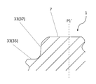
- the main body 3 may have a second recess 33 located from the first surface 7 to the side surface 11.
- the second recess 33 may have a second bottom surface 35 and a second wall surface 37 located between the second bottom surface 35 and the first surface 7.
- the insert 1 can be stably fixed to the holder by bringing the second recess 33 in the insert 1 into contact with the holder.
- the second wall surface 37 may have a sixth surface 39, a seventh surface 41 and an eighth surface 43.
- the sixth surface 39 and the seventh surface 41 may have a flat surface shape.
- the eighth surface 43 is located between the sixth surface 39 and the seventh surface 41 and may be concave toward the outer peripheral side of the main body 3.
- the surface relatively near the first cutting edge 17 is the seventh surface 41.
- the surface located relatively away from the first cutting edge 17 is the sixth surface 39.
- the second bottom surface 35 may be parallel to the first surface 7.
- the sixth surface 39 and the seventh surface 41 of the second wall 37 may be parallel to the central axis P1.
- the sixth surface 39 and the seventh surface 41 of the second wall surface 37 may be parallel to the central axis P1 or may be inclined relative to the central axis P1.
- the sixth surface 39 in the example shown in FIGS. 10 to 12 is inclined so as to be closer to the axis P1 'as it goes from the side of the second bottom surface 35 to the side of the first surface 7.
- 10 to 12 show cross sections orthogonal to the first surface 7 and the sixth surface 39. As shown in FIG.
- the fourth surface 29 may be inclined so as to approach the axis P1 ′ as it goes from the side of the first bottom surface 23 to the side of the first surface 7.
- FIG. 12 shows a cross section orthogonal to the first surface 7 and the fourth surface 29.
- the inclination angle of the fourth surface 29 with respect to the axis P1 ' can be set to, for example, about 20 to 70 degrees.
- the insert 1 When the first surface 7 is viewed from the front, a force that tends to rotate in a counterclockwise direction with respect to the central axis P1 of the through hole 19 is applied to the main body 3 by the main component force applied at the time of cutting.
- the insert 1 can be held at the portion of the holder that faces the sixth surface 39.
- the insert 1 can be held at a portion facing the seventh surface 41 in the holder against a back force applied to the main body 3 at the time of cutting.
- the surface located away from the first cutting edge 17 may be the fourth surface 29.
- the sixth surface 39 may be a surface located away from the first cutting edge 17 among the sixth surface 39 and the seventh surface 41. At this time, when the first surface 7 is viewed from the front, the distance between the ridge line where the first surface 7 and the fourth surface 29 intersect and the ridge line where the first surface 7 and the sixth surface 39 intersect is the first cutting edge The distance from 17 may be wider.
- the ridge line where the first surface 7 and the fourth surface 29 intersect and the ridge line where the first surface 7 and the sixth surface 39 intersect may extend in a parallel direction.
- the bisector L6 of the angle formed by the virtual extension line L3 and the virtual extension line L5 is parallel to the ridge line where the first surface 7 and the fourth surface 29 intersect. It may be In addition, the bisector L6 may be parallel to the ridge line where the first surface 7 and the sixth surface 39 intersect.
- the virtual extension line L3 indicates a ridge line at which the first surface 7 and the third surface 27 intersect.
- the virtual extension line L5 indicates a ridge line at which the first surface 7 and the seventh surface 41 intersect.
- the bisector L6 described above does not have to be strictly parallel to the ridgeline where the first surface 7 and the fourth surface 29 intersect, and may be inclined at about -10 to 10 °. Similarly, the bisector L6 described above does not have to be strictly parallel to the ridgeline where the first surface 7 and the sixth surface 39 intersect, and may be inclined at about -10 to 10 °.
- the virtual extension line L3 and the virtual extension line L7 may intersect at the outside of the insert 1.
- the virtual extension line L7 indicates a ridge line at which the first surface 7 and the sixth surface 39 meet.
- the fourth surface 29 and the sixth surface 39 sandwich the fourth surface 29 and the sixth surface 39 in the direction perpendicular to the direction.
- the width of the covered surface is wide. Therefore, the thickness of the surface sandwiched by the fourth surface 29 and the sixth surface 39 can be easily secured, and the fracture resistance of the insert 1 is high.
- the side surface 11 may have a third side surface 45 and a fourth side surface 47.
- the third side surface 45 is located farther from the first cutting edge 17 than the perpendicular L ⁇ b> 2, and the radius of curvature may be constant.
- the fourth side surface 47 may be located between the third side surface 45 and the first side surface 13 and may be narrower than the third side surface 45 with respect to the through hole 19.
- the side surface 11 has the third side surface 45 and the fourth side surface 47
- chips generated by the first cutting edge 17 pass through the first side surface 13 having the rake surface area 13a to the fourth side surface 47. It may flow.
- the distance between the fourth side surface 47 and the through hole 19 is relatively narrow as described above, it is easy to secure a space for chips to flow on the fourth side surface 47. Therefore, the insert 1 satisfying such a configuration has high chip dischargeability.
- the size of the main body 3 is not particularly limited.
- the length from the central axis P1 to the first cutting edge 17 may be about 3 to 20 mm.
- the distance between the first surface 7 and the second surface 9 may be, for example, about 2 to 20 mm.
- Examples of the material of the insert 1 include cemented carbide and cermet.
- Examples of the composition of the cemented carbide include WC-Co, WC-TiC-Co, and WC-TiC-TaC-Co.
- WC-Co is produced by adding a powder of cobalt (Co) to tungsten carbide (WC) and sintering it.
- WC-TiC-Co is obtained by adding titanium carbide (TiC) to WC-Co.
- WC-TiC-TaC-Co is obtained by adding tantalum carbide (TaC) to WC-TiC-Co.
- cermet is a sintered composite material in which a ceramic component is compounded with a metal.
- a member containing a titanium compound such as titanium carbide (TiC) and titanium nitride (TiN) as a main component is mentioned.
- the surface of the insert 1 may be coated with a film using a chemical vapor deposition (CVD) method or a physical vapor deposition (PVD) method.
- the composition of the film may, for example, be titanium carbide (TiC), titanium nitride (TiN), titanium carbonitride (TiCN) or alumina (Al 2 O 3 ).
- insert 1 'of the embodiment will be described using the drawings.
- insert 1 'of this embodiment may have the same composition as insert 1, and explanation may be omitted about this same composition.
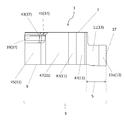
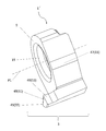
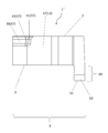
- Another insert 1 'of the embodiment has a generally flat body 3 as shown in FIG.
- the main body 3 has a first surface 7, a second surface 9 located on the opposite side of the first surface 7, and a side surface 11 located between the first surface 7 and the second surface 9.
- the main body 3 has a through hole 19 opened in the first surface 7 and the second surface 9.
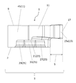
- the main body 3 in the example shown in FIG. 13 has a protrusion 49 which is located on the second surface 9 and protrudes from the second surface 9 in a direction away from the first surface 7.
- the protrusion 49 is a portion corresponding to the cutting portion in the insert 1 described above.
- the protrusion 49 in the example shown in FIG. 13 protrudes in the direction along the central axis P1 of the through hole 19.
- the protrusion 49 has a second cutting edge 51 located at a position farthest from the first surface 7.
- a protrusion 49 extends from the second surface 9 and is adjacent to the first protrusion 53 having a rake surface area and the first protrusion 53 and located at the tip of the protrusion 49.
- a second projecting surface 55 having a flank surface area, and a second cutting edge 51 positioned at at least a part of a ridge line where the first projecting surface 53 and the second projecting surface 55 intersect.
- the insert 1 has the first cutting edge 17 located at at least a part of the ridge line where the first side surface 13 and the second side surface 15 intersect, while the insert 1 ′ has the first projecting surface 53.
- the 2nd cutting surface 51 has the 2nd cutting blade 51 located in at least one part of the ridgeline which meets.
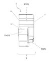
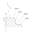
- the main body 3 has a first recess 21 extending from the first surface 7 to the side surface 11.
- the first recess 21 in the example shown in FIG. 14 has a first bottom surface 23 and a first wall surface 25 located between the first bottom surface 23 and the first surface 7.
- the first recess 21 in the example shown in FIG. 14 is located apart from the virtual straight line L8 when the first surface 7 is seen through from the front.
- the virtual straight line L8 connects the center of the second cutting edge 51 and the central axis P1 of the through hole 19. Since the insert 1 ′ in the example shown in FIG. 14 has the above-described configuration, similarly to the insert 1, the durability on the imaginary straight line L ⁇ b> 8 to which a load is easily applied during cutting is high.
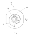
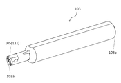
- the cutting tool 101 of the embodiment includes a holder 103 and an insert 1 represented by the above-described embodiment, as shown in FIG. In FIG. 18 to FIG. 22, the insert 1 is shown as a cutting insert.
- the cutting tool 101 may have an insert 1 'instead of the insert 1 without any problem.
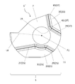
- the holder 103 is a rod-like shape extending from the first end 103a (lower left end in FIG. 18) to the second end 103b (upper right end in FIG. 18), and has a pocket 105 on the side of the first end 103a.
- the cutting tool 101 in an example shown in FIG. 19 and the like includes a screw 107 as a fixing tool.
- the pocket 105 may have a threaded hole 109 extending from the side of the first end to the side of the second end as shown in FIG.
- the insert 1 can be fixed to the holder 103 by inserting the screw 107 into the screw hole 109 in the holder 103 and the through hole 19 in the insert 1. Specifically, the screw 107 is inserted into the through hole 19 formed in the insert 1, and the tip of the screw 107 is inserted into the screw hole 109 formed in the holder 103. Then, the screw 107 is screwed into the screw hole 109.
- the extending direction of the rod-like holder 103 may coincide with the extending direction of the central axis P1 of the insert 1.
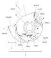
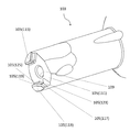
- the pocket 105 may have a bottom portion 111, a first convex portion 113, and a second convex portion 115 as illustrated in FIG.
- the bottom portion 111 is a portion facing the first surface.
- the bottom portion 111 may be in contact with the first surface of the insert 1 and may have a flat surface shape.
- the first convex portion 113 is a portion facing the first concave portion.
- the second convex portion 115 is a portion facing the second concave portion.
- the first convex portion 113 and the second convex portion 115 may respectively project from the bottom portion 111 along the direction from the side of the second end 103 b toward the side of the first end 103 a.
- the first convex portion 113 may be in contact with the first concave portion
- the second convex portion 115 may be in contact with the second concave portion.
- the first convex portion 113 in the example shown in FIG. 24 has a ninth surface 117 facing the third surface and a tenth surface 119 facing the fourth surface.
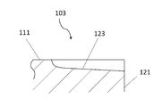
- the pocket 105 further includes a first portion 123 located between the bottom portion 111 and the ninth surface 117 and a second portion 125 located between the bottom portion 111 and the tenth surface 119.
- the first portion 123 may be a curved surface connecting the bottom portion 111 and the ninth surface 117.
- the second portion 125 may be a curved surface connecting the bottom portion 111 and the tenth surface 119.
- first portion 123 and the second portion 125 have a groove shape. Specifically, a portion corresponding to the first portion 123 is shown as a first groove portion 123, and a portion corresponding to the second portion 125 is shown as a second groove portion 125. In such a configuration, the width W 1 of the first groove 123 may be larger than the width W 2 of the second groove 125.
- a main component is likely to be applied to the insert 1 in the direction from the first cutting edge toward the flank region during cutting. Therefore, the insert 1 is easy to rotate in the F1 direction which is a clockwise direction with reference to the central axis P2 of the screw hole 109. At this time, a force is easily applied to the ninth surface 117 opposed to the third surface, and stress is easily concentrated between the bottom portion 111 and the ninth surface 117. However, when the insert 1 has the above-described configuration, concentration of stress applied between the bottom 111 and the ninth surface 117 is easily avoided. Therefore, the strength of the holder 103 is high.
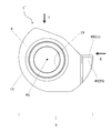
- the width W1 of the first groove portion 123 may be evaluated by the width in the direction orthogonal to the extending direction of the first groove portion 123, as shown in FIG.
- FIG. 25 is a view of the holder 103 viewed from the first end.
- the width W2 of the second groove 125 may be evaluated by the width in the direction orthogonal to the extending direction of the second groove 125, as shown in FIG.
- the whole of the bottom portion 111 may be in contact with the first surface, and only a part of the bottom portion 111 may be in contact with the first surface.
- the entire first protrusion 113 may be in contact with the first recess, or only a part of the first protrusion 113 may be in contact with the first recess.
- the entire second protrusion 115 may be in contact with the second recess, or only a part of the second protrusion 115 may be in contact with the second recess.
- the entire ninth surface 117 may be in contact with the third surface, or only a portion of the ninth surface 117 may be in contact with the third surface.
- the whole of the tenth surface 119 may be in contact with the fourth surface, or only a part of the tenth surface 119 may be in contact with the fourth surface.
- the first groove portion 123 may have a portion which becomes shallow as it is separated from the outer peripheral surface 121 of the holder 103.
- the stress tends to be concentrated toward the portion closer to the outer peripheral surface 121 of the holder 103.
- the portion closer to the outer peripheral surface 121 of the holder 103 Stress concentration is relieved.
- the thickness in the vicinity of the screw hole 109 in the holder 103 can be secured. Therefore, the strength of the holder 103 can be improved.
- the groove bottom of the first groove 123 may have a curved shape, or may have a linear shape as shown in FIG.
- the pocket 105 may have a threaded hole 109 extending from the side of the first end 103 a to the side of the second end 103 b at the bottom 111.
- the first groove portion 123 may be in contact with the screw hole 109 and may be separated from the screw hole 109. In the example shown in FIG. 25, the first groove 123 is separated from the screw hole 109.
- the central axis P2 of the screw hole 109 in the holder 103 and the central axis P1 of the through hole 19 in the insert 1 may be coincident with or offset from each other.
- the central axes P1 and P2 coincide with each other, screwing of the insert 1 to the holder 103 can be easily performed.
- FIG. 22 shows the central axis P2 and the central axis P1 in a state in which the screw is removed. Further, in FIG. 22, the central axis P2 is indicated by a point. Note that FIG. 22 shows the cutting tool 101 in the case where the holder 103 is seen through in a plan view toward the first end.
- an imaginary straight line L9 parallel to the ridge line where the first surface 7 and the third surface 27 intersect is set. Further, an imaginary straight line parallel to the imaginary straight line L9 and passing through the central axis P1 of the through hole 19 is taken as an imaginary straight line L9 '.
- the central axis P2 may be located on the side of the first recess 21 with respect to the imaginary straight line L9 '. As described above, when the central axis P2 is eccentric with respect to the central axis P1, when the insert 1 is fixed to the holder 103 by the screw 107, the screw 107 is not easily loosened.
- the central axis P2 may be located farther from the first cutting edge 17 than the central axis P1 in the direction along the imaginary straight line L9 '. Even in such a case, when the insert 1 is fixed to the holder 103 by the screw 107, the screw 107 is not easily loosened.
- steel, cast iron or the like can be used.
- high toughness steel may be used among these members.
- the machined product is produced by cutting a work material.
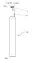
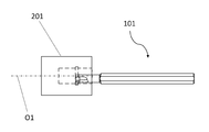
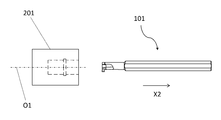
- the method of manufacturing a machined product according to the embodiment includes the following steps. That is, (1) a step of rotating the work material 201; (2) contacting the first cutting edge of the cutting tool 101 represented by the above embodiment with the rotating workpiece 201; (3) releasing the cutting tool 101 from the work material 201; Is equipped.
- the work material 201 is rotated around the axis O1, and the cutting tool 101 is brought relatively close to the work material 201.
- the first cutting edge of the cutting tool 101 is brought into contact with the rotating work material 201, and the work material 201 is cut.
- the cutting tool 101 is relatively moved away from the work material 201.
- the cutting tool 101 is moved in the X1 direction to approach the work material 201. Further, in FIG. 28, the work material 201 is cut by bringing the first cutting edge of the insert into contact with the work material 201 being rotated. Further, in FIG. 29, the cutting tool 101 is moved away in the X2 direction in a state where the work material 201 is rotated.
- the cutting tool 101 is brought into contact with the work material 201 by moving the cutting tool 101 in each process, or the cutting tool 101 is separated from the work material 201
- the cutting tool 101 is not limited to such a form.
- the work material 201 may be brought close to the cutting tool 101.
- the work material 201 may be moved away from the cutting tool 101.
- the step of rotating the work material 201 may be maintained, and the process of bringing the first cutting edge in the insert into contact with different portions of the work material 201 may be repeated.
- cut material 201 carbon steel, alloy steel, stainless steel, cast iron, or nonferrous metal etc. are mentioned, for example.
- this indication is not limited to embodiment mentioned above, It can not be overemphasized that it can be arbitrary unless it deviates from the gist of this indication.
Abstract
One mode of embodiment of an insert according to the present invention is provided with a main body including: a first surface; a second surface positioned on the opposite side to the first surface; a side surface positioned between the first surface and the second surface; a first cutting edge positioned on at least part of a ridge line where a first side surface and a second side surface adjacent to the first side surface intersect, where the first side surface and the second side surface are within the side surface; and a through hole which opens in the first surface and the second surface. The main body additionally includes a first recessed portion extending from the first surface to the side surface, wherein, when the first surface is viewed from in front, the first recessed portion is positioned away from a virtual straight line joining the first cutting edge and the center of the through hole.
Description
本出願は、2017年7月11日に出願された日本国特許出願2017-135567号及び2017年10月6日に出願された日本国特許出願2017-195958号の優先権を主張するものであり、これらの先の出願の開示全体を、ここに参照のために取り込む。
This application claims priority to Japanese Patent Application No. 2017-135567 filed on Jul. 11, 2017 and Japanese Patent Application No. 2017-195958 filed on October 6, 2017. The entire disclosure of these prior applications is incorporated herein by reference.
本態様は、一般的には、切削インサート、切削工具及び切削加工物の製造方法に関する。より具体的には、溝入れ加工に用いられる切削工具に関する。
The present aspect generally relates to a cutting insert, a cutting tool, and a method of manufacturing a machined product. More specifically, the present invention relates to a cutting tool used for grooving.
被削材を切削加工する際に用いられる切削工具として、例えば、特表2014-504561号公報(特許文献1)に記載の切削工具が知られている。特許文献1に記載の切削工具におけるインサートは、上面の側に位置する凹部を有している。また、特許文献1に記載の切削工具におけるホルダは、上記の凹部に対応する凸部を有している。上記の凹部を凸部に嵌め合わせることによって、インサートが安定してホルダに拘束される。特許文献1に記載のインサートにおいては、上面を正面視したとき、インサートの切刃と貫通穴の中心軸とを結ぶ仮想線上に凹部が位置している。
As a cutting tool used when cutting a work material, for example, a cutting tool described in Japanese Patent Application Publication No. 2014-504561 (Patent Document 1) is known. The insert in the cutting tool described in Patent Document 1 has a recess located on the upper surface side. Moreover, the holder in the cutting tool of patent document 1 has the convex part corresponding to said recessed part. By fitting the above-mentioned concave portion to the convex portion, the insert is stably restrained by the holder. In the insert described in Patent Document 1, when the upper surface is viewed from the front, the recess is located on a virtual line connecting the cutting edge of the insert and the central axis of the through hole.
態様の一つのインサートは、第1面と、該第1面の反対側に位置する第2面と、前記第1面及び前記第2面の間に位置する側面と、該側面のうち第1側面と該第1側面に隣り合う第2側面とが交わる稜線の少なくとも一部に位置する第1切刃と、前記第1面及び前記第2面において開口する貫通穴とを有する本体を備えている。前記本体は、前記第1面から前記側面にわたる第1凹部をさらに有している。該第1凹部は、前記第1面を正面から見た場合に、前記第1切刃と前記貫通穴の中心とを結ぶ仮想直線から離れて位置している。
One insert of the aspect has a first surface, a second surface located on the opposite side of the first surface, a side surface located between the first surface and the second surface, and a first one of the side surfaces. And a main body having a first cutting edge located at least a part of a ridge line where a side surface and a second side surface adjacent to the first side intersect and a through hole opening at the first surface and the second surface There is. The body further includes a first recess extending from the first surface to the side surface. The first recess is located apart from a virtual straight line connecting the first cutting edge and the center of the through hole when the first surface is viewed from the front.
<切削インサート>
以下、複数の実施形態の切削インサート1(以下、単にインサート1ともいう。)について、それぞれ図面を用いて詳細に説明する。但し、以下で参照する各図は、説明の便宜上、各実施形態を説明する上で必要な主要部材のみを簡略化して示したものである。したがって、本開示のインサート1は、参照する各図に示されていない任意の構成部材を備え得る。また、各図中の部材の寸法は、実際の構成部材の寸法及び各部材の寸法比率等を忠実に表したものではない。 <Cutting insert>
Hereinafter, cutting inserts 1 (hereinafter, also simply referred to as inserts 1) according to a plurality of embodiments will be described in detail with reference to the drawings. However, for convenience of explanation, the drawings referred to in the following simply show only the main members necessary for describing each embodiment. Thus, theinsert 1 of the present disclosure may comprise any component not shown in the figures to which it refers. Further, the dimensions of the members in the respective drawings do not faithfully represent the dimensions of the actual constituent members, the dimensional ratio of the respective members, and the like.
以下、複数の実施形態の切削インサート1(以下、単にインサート1ともいう。)について、それぞれ図面を用いて詳細に説明する。但し、以下で参照する各図は、説明の便宜上、各実施形態を説明する上で必要な主要部材のみを簡略化して示したものである。したがって、本開示のインサート1は、参照する各図に示されていない任意の構成部材を備え得る。また、各図中の部材の寸法は、実際の構成部材の寸法及び各部材の寸法比率等を忠実に表したものではない。 <Cutting insert>
Hereinafter, cutting inserts 1 (hereinafter, also simply referred to as inserts 1) according to a plurality of embodiments will be described in detail with reference to the drawings. However, for convenience of explanation, the drawings referred to in the following simply show only the main members necessary for describing each embodiment. Thus, the
実施形態の一つのインサート1は、図1に示すように、平板形状の本体3を有している。
One insert 1 of the embodiment has a flat plate-shaped main body 3 as shown in FIG.
本体3は、第1面7と、第1面7の反対側に位置する第2面9と、第1面7及び第2面9の間に位置する側面11とを有している。図1に示す一例のように、第1面7及び第2面9が互いに平行となっていてもよい。側面11は、図1及び図2に示すように、第1側面13及びこの第1側面13に隣り合う第2側面15を有している。
The main body 3 has a first surface 7, a second surface 9 located on the opposite side of the first surface 7, and a side surface 11 located between the first surface 7 and the second surface 9. As an example shown in FIG. 1, the first surface 7 and the second surface 9 may be parallel to each other. The side surface 11 has a first side surface 13 and a second side surface 15 adjacent to the first side surface 13 as shown in FIGS. 1 and 2.
第1側面13及び第2側面15は交わっていてもよい。このとき、本体3は、第1側面13及び第2側面15が交わる稜線の少なくとも一部に位置する第1切刃17を有していてもよい。図2に示す一例における第1側面13は、第1切刃17から延びており、凹面形状を有している。また、図2に示す一例における第2側面15は、第1切刃17から延びており、平面形状を有している。
The first side 13 and the second side 15 may intersect. At this time, the main body 3 may have a first cutting edge 17 located at at least a part of a ridge line where the first side surface 13 and the second side surface 15 intersect. The first side surface 13 in the example shown in FIG. 2 extends from the first cutting edge 17 and has a concave shape. Further, the second side surface 15 in the example shown in FIG. 2 extends from the first cutting edge 17 and has a planar shape.
第1側面13は、図3に示すように、すくい面領域13aを有していてもよい。また、第2側面15は、逃げ面領域15aを有していてもよい。すくい面領域13aは、切削加工時に切屑に接触して切屑をカールさせることが可能な領域である。図3に示す一例において、すくい面領域13aは、第1側面13のうち第1切刃17に沿った部分に位置している。逃げ面領域15aは、切削加工時に被削材の仕上げ面との接触が少なくなるように逃がされた領域である。図3に示す一例において、逃げ面領域15aは、第2側面15のうち第1切刃17に沿った部分に位置している。なお、逃げ面領域15aは、切削加工時において仕上げ面に全く接触しないことは要求されない。
The first side surface 13 may have a rake surface area 13a as shown in FIG. In addition, the second side surface 15 may have a flank surface area 15a. The rake surface area 13a is an area that can contact chips and cause the chips to curl during cutting. In the example shown in FIG. 3, the rake surface area 13 a is located on a portion of the first side surface 13 along the first cutting edge 17. The flank surface area 15a is an area which is escaped so as to reduce the contact with the finished surface of the work material at the time of cutting. In the example shown in FIG. 3, the flank surface area 15 a is located on a portion of the second side surface 15 along the first cutting edge 17. In addition, the flank surface area 15a is not required to be in no contact with the finished surface at the time of cutting.
第1切刃17は、第1側面13及び第2側面15が交わる稜線の一部のみに位置していてもよく、また、全体に位置していてもよい。第1側面13及び第2側面15が交わる稜線に位置する第1切刃17は、いわゆるホーニング加工が施されていてもよい。すなわち、第1側面13及び第2側面15が交わる稜線は、2つの面が交わることによる厳密な線形状ではなくてもよい。
The first cutting edge 17 may be located at only a part of the ridge line where the first side surface 13 and the second side surface 15 intersect, or may be located at the whole. A so-called honing process may be applied to the first cutting edge 17 located at a ridge line where the first side surface 13 and the second side surface 15 intersect. That is, the ridgeline which the 1st side 13 and the 2nd side 15 cross may not be a strict line shape by two sides crossing.
本体3は、図1などに示すように、第1面7及び第2面9において開口する貫通穴19を有している。図1などに示す一例におけるインサート1は、第1側面13、第2側面15及び第1切刃17によって構成される切削部5を有している。切削部5は、貫通穴19の中心軸P1から離れる方向に突出していてもよい。それゆえ、第1切刃17は、貫通穴19の中心軸P1から最も離れて位置していてもよい。
The main body 3 has a through hole 19 opened at the first surface 7 and the second surface 9 as shown in FIG. The insert 1 in the example shown in FIG. 1 and the like has a cutting portion 5 constituted by a first side surface 13, a second side surface 15 and a first cutting edge 17. The cutting portion 5 may protrude in a direction away from the central axis P1 of the through hole 19. Therefore, the first cutting edge 17 may be located farthest from the central axis P1 of the through hole 19.
貫通穴19は、インサート1をホルダに装着する際の固定具の挿入穴として用いられてもよい。固定具の例として、ネジ、くさび及びろう材などが挙げられる。
The through hole 19 may be used as an insertion hole of the fixture when mounting the insert 1 to the holder. Examples of fasteners include screws, wedges and brazes.
本体3は、上記した通り平板形状であってもよく、第1面7及び第2面9の外径が、本体3の厚みよりも大きくてもよい。ただし、図1は一例であって、本体3の形状は図1に示す形状に限定されない。
The main body 3 may have a flat plate shape as described above, and the outer diameters of the first surface 7 and the second surface 9 may be larger than the thickness of the main body 3. However, FIG. 1 is an example, and the shape of the main body 3 is not limited to the shape shown in FIG.
実施形態の本体3は、第1面7から側面11にわたる第1凹部21を有している。図6に示す一例における第1凹部21をホルダに当接させることによって、インサート1がホルダに安定して固定され易い。
The main body 3 of the embodiment has a first recess 21 extending from the first surface 7 to the side surface 11. By bringing the first recess 21 in the example shown in FIG. 6 into contact with the holder, the insert 1 can be stably fixed to the holder.
実施形態の本体3においては、第1面7を正面から見た場合に、第1凹部21が仮想直線L1から離れて位置している。ここで、仮想直線L1は、第1切刃17と貫通穴19の中心軸P1とを結んでいる。中心軸P1は第1面7及び第2面9に対して直交していてもよい。この場合には、図2に示すように第1面7を正面から見た際に、中心軸P1が点で示される。
In the main body 3 of the embodiment, when the first surface 7 is viewed from the front, the first recess 21 is located apart from the virtual straight line L1. Here, the virtual straight line L1 connects the first cutting edge 17 and the central axis P1 of the through hole 19. The central axis P1 may be orthogonal to the first surface 7 and the second surface 9. In this case, when the first surface 7 is viewed from the front as shown in FIG. 2, the central axis P1 is indicated by a point.
仮想直線L1は、切削加工時に負荷がかかり易い領域に位置する。第1凹部21が、第1切刃17と貫通穴19の中心軸P1とを結ぶ仮想直線L1から離れて位置している場合には、切削加工時に負荷がかかり易い領域において本体3の肉厚が確保され易い。したがって、第1凹部21によってインサート1をホルダに安定して固定しつつ、インサート1の耐久性が高い。
The virtual straight line L1 is located in a region where load is likely to be applied during cutting. When the first recess 21 is located apart from the virtual straight line L1 connecting the first cutting edge 17 and the central axis P1 of the through hole 19, the thickness of the main body 3 in the region where load is likely to be applied during cutting Is easy to secure. Therefore, the durability of the insert 1 is high while the insert 1 is stably fixed to the holder by the first recess 21.
既に示した通り、第1側面13がすくい面領域13aを有していてもよく、また、第2側面15が逃げ面領域15aを有していてもよい。図2に示す一例においては、第1凹部21が、仮想直線L1に対して第1側面13の側(図2における上側)ではなく、第2側面15の側(図2における下側)に位置している。
As already indicated, the first side surface 13 may have a rake surface area 13a, and the second side surface 15 may have a flank surface area 15a. In the example shown in FIG. 2, the first recess 21 is located not on the side of the first side 13 (upper side in FIG. 2) but on the side of the second side 15 (lower side in FIG. 2) with respect to the imaginary straight line L1. doing.
切削加工時においては、第1切刃17に対して、すくい面領域13aの側に向かう方向(図2における右方向)よりも逃げ面領域15aの側に向かう方向(図2における下方向)に主分力が加わり易い。このとき、第1面7を正面から見た場合において第1凹部21が第2側面15の側に位置している場合には、上記の主分力を、ホルダにおける第1壁面25に対向する部分で受け止め易い。そのため、固定具に過度の負荷が加わることを避けつつインサート1がホルダに安定して固定され易い。
At the time of cutting, with respect to the first cutting edge 17, in the direction (downward direction in FIG. 2) toward the flank surface region 15a rather than the direction (rightward direction in FIG. 2) toward the rake surface region 13a. Main component is easy to add. At this time, when the first recess 21 is located on the second side surface 15 when the first surface 7 is viewed from the front, the main component of the force is opposed to the first wall surface 25 of the holder. It is easy to catch in part. Therefore, the insert 1 is likely to be stably fixed to the holder while avoiding an excessive load on the fixture.
また、切削加工時において、第1切刃17に対して逃げ面領域15aの側に向かう方向に主分力が加わり易い。そのため、第1面7を正面から見た場合、インサート1は、貫通穴19の中心軸P1を基準として反時計回りの方向に回転し易い。このとき、第1凹部21が上記の位置にある場合には、ホルダにおける第1壁面25に対向する部分が、第1切刃17から反時計回りの方向における比較的近いところに位置することになる。そのため、インサート1がホルダに安定して固定され易い。
Further, at the time of cutting, a main component is likely to be applied in the direction toward the flank surface region 15a with respect to the first cutting edge 17. Therefore, when the first surface 7 is viewed from the front, the insert 1 is likely to rotate in the counterclockwise direction with reference to the central axis P1 of the through hole 19. At this time, when the first recess 21 is in the above position, the portion of the holder facing the first wall surface 25 is positioned relatively near to the first cutting edge 17 in the counterclockwise direction. Become. Therefore, the insert 1 is likely to be stably fixed to the holder.
第1凹部21は貫通穴19に接していても離れていてもよいが、図2に示す一例のように、第1凹部21が貫通穴19から離れていてもよい。インサート1は、固定具によってホルダに固定されることから、本体3における貫通穴19の周りには負荷が加わり易い。第1凹部21が貫通穴19から離れている場合には、負荷の加わり易い貫通穴19の周りの肉厚が確保される。そのため、貫通穴19の周りにおけるクラックの発生が抑制される。
The first recess 21 may be in contact with or separated from the through hole 19, but as in the example shown in FIG. 2, the first recess 21 may be separated from the through hole 19. Since the insert 1 is fixed to the holder by the fixing tool, a load is easily applied around the through hole 19 in the main body 3. When the first recess 21 is separated from the through hole 19, the thickness around the through hole 19 to which load is easily applied is secured. Therefore, the occurrence of a crack around the through hole 19 is suppressed.
図6に示すように、第1凹部21は、第1底面23と、第1底面23及び第1面7の間に位置する第1壁面25とを有していてもよい。図6に示す一例においては、第1底面23は、中心軸P1に概ね直交するように位置している。また、第1壁面25は、第1底面23に概ね直交するように位置している。なお、上記の「概ね直交」とは、厳密に直交している構成に限定されず、80~100°程度の範囲であることを許容する概念である。
As shown in FIG. 6, the first recess 21 may have a first bottom surface 23 and a first wall surface 25 located between the first bottom surface 23 and the first surface 7. In the example shown in FIG. 6, the first bottom surface 23 is positioned substantially orthogonal to the central axis P1. Further, the first wall surface 25 is positioned to be substantially orthogonal to the first bottom surface 23. Note that the above “generally orthogonal” is a concept that is not limited to the configuration that is strictly orthogonal but allows a range of about 80 to 100 °.
インサート1における第1底面23及び第1壁面25をホルダに当接させることによってインサート1をホルダに安定して固定することが可能である。第1底面23は、凹面又は凸面であってもよく、また、図6に示す一例のように、第1面7と平行な面であってもよい。
By bringing the first bottom surface 23 and the first wall surface 25 of the insert 1 into contact with the holder, the insert 1 can be stably fixed to the holder. The first bottom surface 23 may be a concave surface or a convex surface, or may be a surface parallel to the first surface 7 as in the example shown in FIG.
また、図2に示す一例のように、第1壁面25が、垂線L2を挟んで位置する第3面27及び第4面29を有していてもよい。ここで、図2に示す一例における垂線L2は、仮想直線L1に対して直交しており、また、貫通穴19の中心軸P1を通っている。また、上記の垂線L2よりも第1切刃17の近くに位置する面を第3面27、上記の垂線L2よりも第1切刃17から離れて位置する面を第4面29としている。
In addition, as in the example shown in FIG. 2, the first wall surface 25 may have a third surface 27 and a fourth surface 29 which are positioned to sandwich the perpendicular L2. Here, the perpendicular line L2 in the example shown in FIG. 2 is orthogonal to the imaginary straight line L1 and passes through the central axis P1 of the through hole 19. Further, a surface located closer to the first cutting edge 17 than the perpendicular L2 is a third surface 27, and a surface located farther from the first cutting edge 17 than the perpendicular L2 is a fourth surface 29.
第1壁面25が第3面27を有している場合には、ホルダにおける第3面27に対向する部分が、固定具よりも第1切刃17の近くに位置し易い。この場合には、固定具に加わる負荷が小さくなるため、ホルダにおける第3面27に対向する部分で、インサート1をより安定して固定することが可能である。
When the first wall surface 25 has the third surface 27, the portion of the holder facing the third surface 27 tends to be closer to the first cutting edge 17 than the fixing tool. In this case, since the load applied to the fixture is reduced, it is possible to more stably fix the insert 1 at a portion of the holder facing the third surface 27.
また、第1壁面25が第4面29を有している場合には、第1壁面25が垂線L2を挟んで位置し易い。この場合には、固定具に加わる負荷をより一層小さくすることが可能となることから、インサート1をさらに安定して固定することが可能である。
In addition, when the first wall surface 25 has the fourth surface 29, the first wall surface 25 can be easily positioned across the perpendicular L2. In this case, the load applied to the fixture can be further reduced, so that the insert 1 can be more stably fixed.
第1壁面25は、貫通穴19の中心軸P1に対して概ね平行であってもよく、また、貫通穴19の中心軸P1に対して傾斜していてもよい。なお、図7に示す一例などにおいては、視覚的な理解を容易にするため、第1面7と交差し、貫通穴19の中心軸P1に平行な仮想直線を軸P1’として、この軸P1’と第1壁面25とを比較している。なお、上記の平行とは、対象となる2つの部位が厳密な意味で平行な位置関係でなくてもよい。具体的には、対象となる2つの部位が5°程度傾斜していても平行と見做してもよい。
The first wall surface 25 may be substantially parallel to the central axis P1 of the through hole 19 or may be inclined with respect to the central axis P1 of the through hole 19. In the example shown in FIG. 7 and the like, in order to facilitate visual understanding, an imaginary straight line which intersects the first surface 7 and is parallel to the central axis P1 of the through hole 19 is taken as an axis P1 '. 'And the first wall 25 are compared. Note that the above-mentioned “parallel” does not have to be a positional relationship in which the two target parts are strictly parallel. Specifically, the two target parts may be inclined by about 5 ° or may be considered parallel.
また、インサート1は、第1壁面25と第1面7とをつなぐ接続面25a及び第1壁面25と第1底面23とをつなぐ接続面25bを有していてもよい。
In addition, the insert 1 may have a connection surface 25 a connecting the first wall surface 25 and the first surface 7 and a connection surface 25 b connecting the first wall surface 25 and the first bottom surface 23.
第1面7を正面から見た場合に、仮想直線L1の延長線と、第1面7及び第3面27の交わる稜線の仮想延長線L3とのなす角をθ1とする。また、第1面7を正面から見た場合に、仮想直線L1の延長線と、仮想直線L4とのなす角をθ2とする。ここで、仮想直線L4は、第1面7及び第3面27の交わる稜線のうち中心軸P1からの距離が最も離れた端部と中心軸P1とを結ぶ直線である。
When the first surface 7 is viewed from the front, the angle between the extension of the virtual straight line L1 and the virtual extension L3 of the ridge line where the first surface 7 and the third surface 27 intersect is θ1. Further, when the first surface 7 is viewed from the front, an angle formed by an extension line of the virtual straight line L1 and the virtual straight line L4 is taken as θ2. Here, the imaginary straight line L4 is a straight line connecting an end portion of the ridge line at which the first surface 7 and the third surface 27 intersect with each other and the central axis P1 at the most distant from the central axis P1.
θ1がθ2よりも小さい場合には、第1面7を正面から見た場合に第3面27が仮想直線L1に対して比較的平行に近い。そのため、第1切刃17に対して加わる主分力が、ホルダにおける第3面27に対向する部分で受け止められ易い。従って、インサート1をホルダに安定して固定することが可能である。なお、上記のθ1及びθ2は特に図示はしていない。
When θ1 is smaller than θ2, when the first surface 7 is viewed from the front, the third surface 27 is relatively parallel to the imaginary straight line L1. Therefore, the main component force applied to the first cutting edge 17 is likely to be received at a portion of the holder facing the third surface 27. Therefore, it is possible to stably fix the insert 1 to the holder. The above θ1 and θ2 are not particularly shown.
また、第1壁面25は、第1面7を正面から見た場合に、第3面27と第4面29との間に位置する第5面31をさらに有していてもよい。第5面31は、本体3の外周側に向かって凸状であってもよい。第5面31が、上記の構成である場合には、第1凹部21及び貫通穴19の間の幅が大きく確保され易い。そのため、貫通穴19の周りにおけるクラックの発生が抑制され易い。
In addition, the first wall surface 25 may further have a fifth surface 31 located between the third surface 27 and the fourth surface 29 when the first surface 7 is viewed from the front. The fifth surface 31 may be convex toward the outer peripheral side of the main body 3. When the 5th surface 31 is said structure, the width | variety between the 1st recessed part 21 and the through-hole 19 is easy to be ensured large. Therefore, the occurrence of a crack around the through hole 19 is easily suppressed.
第5面31が凸状である場合において、第1凹部21及び貫通穴19の間の幅が一定となるように第1凹部21が貫通穴19に沿って位置していてもよい。この場合には、貫通穴19の周りにおけるクラックの発生がさらに抑制され易い。
When the fifth surface 31 is convex, the first recess 21 may be positioned along the through hole 19 so that the width between the first recess 21 and the through hole 19 is constant. In this case, the occurrence of a crack around the through hole 19 can be further suppressed.
また、第5面31は、第1面7を正面から見た場合に、本体3の外周側に対し凹状であってもよい。第5面31が上記の構成である場合には、第1底面23の面積が広く確保され易い。そのため、インサート1がホルダに安定して固定され易い。
The fifth surface 31 may be concave with respect to the outer peripheral side of the main body 3 when the first surface 7 is viewed from the front. When the fifth surface 31 has the above-described configuration, a large area of the first bottom surface 23 is easily secured. Therefore, the insert 1 is likely to be stably fixed to the holder.
また、本体3は、上記の第1凹部21に加えて、第1面7から側面11にわたって位置する第2凹部33を有していてもよい。図2に示す一例のように、第2凹部33が、仮想直線L1に対して第1側面13の側かつ貫通穴19の中心軸P1よりも第1切刃17から離れて位置していてもよい。また、図8に示す一例のように、第2凹部33は、第2底面35と、第2底面35及び第1面7の間に位置する第2壁面37とを有していてもよい。
Further, in addition to the first recess 21 described above, the main body 3 may have a second recess 33 located from the first surface 7 to the side surface 11. As in the example shown in FIG. 2, even if the second recess 33 is located on the side of the first side surface 13 with respect to the imaginary straight line L1 and farther from the first cutting edge 17 than the central axis P1 of the through hole 19 Good. Further, as in the example shown in FIG. 8, the second recess 33 may have a second bottom surface 35 and a second wall surface 37 located between the second bottom surface 35 and the first surface 7.
本体3が、第2凹部33を有している場合には、インサート1における第2凹部33をホルダに当接させることによって、インサート1をホルダに安定して固定できる。
When the main body 3 has the second recess 33, the insert 1 can be stably fixed to the holder by bringing the second recess 33 in the insert 1 into contact with the holder.
図2に示す一例のように、第2壁面37は、第6面39、第7面41及び第8面43を有していてもよい。図2に示す一例のように、第6面39及び第7面41が、平坦な面形状であってもよい。また、第8面43は、第6面39及び第7面41の間に位置しており、本体3の外周側に向かって凹状であってもよい。
As an example shown in FIG. 2, the second wall surface 37 may have a sixth surface 39, a seventh surface 41 and an eighth surface 43. As an example shown in FIG. 2, the sixth surface 39 and the seventh surface 41 may have a flat surface shape. The eighth surface 43 is located between the sixth surface 39 and the seventh surface 41 and may be concave toward the outer peripheral side of the main body 3.
図2に示す一例においては、第6面39及び第7面41のうち相対的に第1切刃17の近くに位置する面が第7面41である。また、第6面39及び第7面41のうち相対的に第1切刃17から離れて位置する面が第6面39である。図2に示す一例のように、第2底面35が第1面7と平行であってもよい。また、第2壁面37における第6面39及び第7面41が中心軸P1に対してそれぞれ平行であってもよい。
In the example shown in FIG. 2, of the sixth surface 39 and the seventh surface 41, the surface relatively near the first cutting edge 17 is the seventh surface 41. Further, of the sixth surface 39 and the seventh surface 41, the surface located relatively away from the first cutting edge 17 is the sixth surface 39. As an example shown in FIG. 2, the second bottom surface 35 may be parallel to the first surface 7. Further, the sixth surface 39 and the seventh surface 41 of the second wall 37 may be parallel to the central axis P1.
第2壁面37における第6面39及び第7面41は、中心軸P1に対してそれぞれ平行であってもよく、また、中心軸P1に対してそれぞれ傾斜していてもよい。図10乃至図12に示す一例における第6面39は、第2底面35の側から第1面7の側に向かうにつれて、軸P1’に近づくように傾斜している。なお、図10乃至図12は、第1面7及び第6面39に直交する断面を示している。
The sixth surface 39 and the seventh surface 41 of the second wall surface 37 may be parallel to the central axis P1 or may be inclined relative to the central axis P1. The sixth surface 39 in the example shown in FIGS. 10 to 12 is inclined so as to be closer to the axis P1 'as it goes from the side of the second bottom surface 35 to the side of the first surface 7. 10 to 12 show cross sections orthogonal to the first surface 7 and the sixth surface 39. As shown in FIG.
切削加工時において、第1切刃17に対して逃げ面領域15aの側に向かう方向(図10における下側)に主分力が加わる。そのため、第1面7を正面から見た場合においてインサート1は、貫通穴19の中心軸P1を基準として反時計回りの方向に回転し易い。このとき、ホルダにおける第6面39に対向する部分に力が加わるところ、上記の構成を有する場合には、インサート1が回転する方向(図11における右方向)だけでなく、貫通穴19の中心軸P1に沿った方向(図11における下方向)にも上記の力を分散させ易い。そのため、インサート1及びホルダが変形しにくく、これらの耐久性が向上する。
At the time of cutting, a principal component force is applied in a direction (lower side in FIG. 10) toward the flank surface area 15a with respect to the first cutting edge 17. Therefore, when the first surface 7 is viewed from the front, the insert 1 is likely to rotate in the counterclockwise direction with reference to the central axis P1 of the through hole 19. At this time, when a force is applied to a portion facing the sixth surface 39 in the holder, in the case of the above configuration, the center of the through hole 19 as well as the direction in which the insert 1 rotates (right direction in FIG. 11) It is easy to disperse the above force in the direction along the axis P1 (downward in FIG. 11). Therefore, the insert 1 and the holder are not easily deformed, and their durability is improved.
また、図12に示す一例のように、第4面29が、第1底面23の側から第1面7の側に向かうにつれて、軸P1’に近づくように傾斜していてもよい。なお、図12は、第1面7及び第4面29に直交する断面を示している。第4面29の軸P1’に対する傾斜角は、例えば、20~70°程度に設定できる。
Further, as in the example shown in FIG. 12, the fourth surface 29 may be inclined so as to approach the axis P1 ′ as it goes from the side of the first bottom surface 23 to the side of the first surface 7. FIG. 12 shows a cross section orthogonal to the first surface 7 and the fourth surface 29. The inclination angle of the fourth surface 29 with respect to the axis P1 'can be set to, for example, about 20 to 70 degrees.
切削加工時に加わる主分力によって、本体3には、第1面7を正面から見た場合において貫通穴19の中心軸P1を基準として反時計回りの方向に回転しようとする力が加わる。この力に対しては、ホルダにおける第6面39に対向する部分でインサート1を保持できる。また、切削加工時に本体3に加わる背分力に対しては、ホルダにおける第7面41に対向する部分でインサート1を保持できる。
When the first surface 7 is viewed from the front, a force that tends to rotate in a counterclockwise direction with respect to the central axis P1 of the through hole 19 is applied to the main body 3 by the main component force applied at the time of cutting. For this force, the insert 1 can be held at the portion of the holder that faces the sixth surface 39. In addition, the insert 1 can be held at a portion facing the seventh surface 41 in the holder against a back force applied to the main body 3 at the time of cutting.
第3面27及び第4面29のうち、第1切刃17から離れて位置する面が第4面29であってもよい。また、第6面39及び第7面41のうち、第1切刃17から離れて位置する面が第6面39であってもよい。このとき、第1面7を正面から見た場合に、第1面7及び第4面29の交わる稜線と、第1面7及び第6面39の交わる稜線との間隔が、第1切刃17から離れるにつれて広くなっていてもよい。
Of the third surface 27 and the fourth surface 29, the surface located away from the first cutting edge 17 may be the fourth surface 29. Further, the sixth surface 39 may be a surface located away from the first cutting edge 17 among the sixth surface 39 and the seventh surface 41. At this time, when the first surface 7 is viewed from the front, the distance between the ridge line where the first surface 7 and the fourth surface 29 intersect and the ridge line where the first surface 7 and the sixth surface 39 intersect is the first cutting edge The distance from 17 may be wider.
また、図2に示す一例のように、第1面7及び第4面29の交わる稜線と、第1面7及び第6面39の交わる稜線とが平行な方向に延びていてもよい。第1凹部21及び第2凹部33が上記の構成である場合には、ホルダへのインサート1の取り付けが容易となる。
Further, as in the example shown in FIG. 2, the ridge line where the first surface 7 and the fourth surface 29 intersect and the ridge line where the first surface 7 and the sixth surface 39 intersect may extend in a parallel direction. When the 1st recessed part 21 and the 2nd recessed part 33 are said structure, attachment of the insert 1 to a holder becomes easy.
さらに、第1面7を正面から見た場合に、仮想延長線L3及び仮想延長線L5のなす角の二等分線L6が、第1面7及び第4面29の交わる稜線に対して平行であってもよい。また、上記の二等分線L6が、第1面7及び第6面39の交わる稜線に対して平行であってもよい。ここで、仮想延長線L3は、第1面7及び第3面27の交わる稜線を示している。また、仮想延長線L5は、第1面7及び第7面41の交わる稜線を示している。第1凹部21及び第2凹部33が上記の構成である場合には、ホルダへのインサート1の取り付けが容易でありつつインサート1をホルダに安定して固定し易い。
Furthermore, when the first surface 7 is viewed from the front, the bisector L6 of the angle formed by the virtual extension line L3 and the virtual extension line L5 is parallel to the ridge line where the first surface 7 and the fourth surface 29 intersect. It may be In addition, the bisector L6 may be parallel to the ridge line where the first surface 7 and the sixth surface 39 intersect. Here, the virtual extension line L3 indicates a ridge line at which the first surface 7 and the third surface 27 intersect. The virtual extension line L5 indicates a ridge line at which the first surface 7 and the seventh surface 41 intersect. When the 1st recessed part 21 and the 2nd recessed part 33 are said structure, while being easy to attach the insert 1 to a holder, it is easy to fix the insert 1 stably to a holder.
なお、上記の二等分線L6は、第1面7及び第4面29の交わる稜線に対して厳密に平行である必要はなく、-10~10°程度傾斜していてもよい。また同様に、上記の二等分線L6は、第1面7及び第6面39の交わる稜線に対して厳密に平行である必要はなく、-10~10°程度傾斜していてもよい。
The bisector L6 described above does not have to be strictly parallel to the ridgeline where the first surface 7 and the fourth surface 29 intersect, and may be inclined at about -10 to 10 °. Similarly, the bisector L6 described above does not have to be strictly parallel to the ridgeline where the first surface 7 and the sixth surface 39 intersect, and may be inclined at about -10 to 10 °.
また、第1面7を正面から見た場合において、仮想延長線L3及び仮想延長線L7が、インサート1の外部で交わっていてもよい。ここで、仮想延長線L7は、第1面7及び第6面39の交わる稜線を示している。
Moreover, when the first surface 7 is viewed from the front, the virtual extension line L3 and the virtual extension line L7 may intersect at the outside of the insert 1. Here, the virtual extension line L7 indicates a ridge line at which the first surface 7 and the sixth surface 39 meet.
仮想延長線L3及び仮想延長線L7が交わる交点がインサート1の外部に位置する場合には、第4面29及び第6面39に垂直な方向における、第4面29及び第6面39で挟まれた面の幅が広い。そのため、第4面29及び第6面39で挟まれた面の肉厚が確保され易く、インサート1の耐欠損性が高い。
When the intersection where the virtual extension line L3 and the virtual extension line L7 intersect is located outside the insert 1, the fourth surface 29 and the sixth surface 39 sandwich the fourth surface 29 and the sixth surface 39 in the direction perpendicular to the direction. The width of the covered surface is wide. Therefore, the thickness of the surface sandwiched by the fourth surface 29 and the sixth surface 39 can be easily secured, and the fracture resistance of the insert 1 is high.
図2に示す一例のように、側面11は、第3側面45及び第4側面47を有していてもよい。図2に示す一例のように、第3側面45は、垂線L2よりも第1切刃17から離れて位置しており、曲率半径が一定であってもよい。第4側面47は、第3側面45及び第1側面13の間に位置しており、第3側面45よりも貫通穴19との間隔が狭くてもよい。
As an example shown in FIG. 2, the side surface 11 may have a third side surface 45 and a fourth side surface 47. As in the example shown in FIG. 2, the third side surface 45 is located farther from the first cutting edge 17 than the perpendicular L <b> 2, and the radius of curvature may be constant. The fourth side surface 47 may be located between the third side surface 45 and the first side surface 13 and may be narrower than the third side surface 45 with respect to the through hole 19.
側面11が第3側面45及び第4側面47を有している場合において、第1切刃17で生じた切屑が、すくい面領域13aを有する第1側面13上を通り第4側面47へと流れる場合がある。第4側面47における貫通穴19との間隔が上記の通り相対的に狭くなっているときには、第4側面47上における切屑の流れるスペースが確保され易い。そのため、このような構成を満たすインサート1は、切屑排出性が高い。
In the case where the side surface 11 has the third side surface 45 and the fourth side surface 47, chips generated by the first cutting edge 17 pass through the first side surface 13 having the rake surface area 13a to the fourth side surface 47. It may flow. When the distance between the fourth side surface 47 and the through hole 19 is relatively narrow as described above, it is easy to secure a space for chips to flow on the fourth side surface 47. Therefore, the insert 1 satisfying such a configuration has high chip dischargeability.
本体3の大きさとしては特に限定されない。例えば、第1面7を正面視した場合に、中心軸P1から第1切刃17までの長さは3~20mm程度であってもよい。また、第1面7及び第2面9の間隔は、例えば2~20mm程度であってもよい。
The size of the main body 3 is not particularly limited. For example, when the first surface 7 is viewed from the front, the length from the central axis P1 to the first cutting edge 17 may be about 3 to 20 mm. Further, the distance between the first surface 7 and the second surface 9 may be, for example, about 2 to 20 mm.
インサート1の材質としては、例えば、超硬合金及びサーメットなどが挙げられる。超硬合金の組成としては、例えば、WC-Co、WC-TiC-Co及びWC-TiC-TaC-Coが挙げられる。WC-Coは、炭化タングステン(WC)にコバルト(Co)の粉末を加えて焼結して生成される。WC-TiC-Coは、WC-Coに炭化チタン(TiC)を添加したものである。WC-TiC-TaC-Coは、WC-TiC-Coに炭化タンタル(TaC)を添加したものである。
Examples of the material of the insert 1 include cemented carbide and cermet. Examples of the composition of the cemented carbide include WC-Co, WC-TiC-Co, and WC-TiC-TaC-Co. WC-Co is produced by adding a powder of cobalt (Co) to tungsten carbide (WC) and sintering it. WC-TiC-Co is obtained by adding titanium carbide (TiC) to WC-Co. WC-TiC-TaC-Co is obtained by adding tantalum carbide (TaC) to WC-TiC-Co.
また、サーメットは、セラミック成分に金属を複合させた焼結複合材料である。具体的には、サーメットとして、炭化チタン(TiC)及び窒化チタン(TiN)などのようなチタン化合物を主成分として含有する部材が挙げられる。
Also, cermet is a sintered composite material in which a ceramic component is compounded with a metal. Specifically, as the cermet, a member containing a titanium compound such as titanium carbide (TiC) and titanium nitride (TiN) as a main component is mentioned.
インサート1の表面は、化学蒸着(CVD)法又は物理蒸着(PVD)法を用いて被膜でコーティングされていてもよい。被膜の組成としては、炭化チタン(TiC)、窒化チタン(TiN)、炭窒化チタン(TiCN)及びアルミナ(Al2O3)などが挙げられる。
The surface of the insert 1 may be coated with a film using a chemical vapor deposition (CVD) method or a physical vapor deposition (PVD) method. The composition of the film may, for example, be titanium carbide (TiC), titanium nitride (TiN), titanium carbonitride (TiCN) or alumina (Al 2 O 3 ).
次に、実施形態の別の一つの切削インサート1´について図面を用いて説明する。ただし、以下においては、この実施形態のインサート1´における上記した実施形態のインサート1との相違点について主に説明する。そのため、インサート1´は、インサート1と同様の構成を有していてもよく、また、この同様の構成については説明を省略する場合がある。
Next, another cutting insert 1 'of the embodiment will be described using the drawings. However, in the following, differences between the insert 1 'of this embodiment and the insert 1 of the above-described embodiment will be mainly described. Therefore, insert 1 'may have the same composition as insert 1, and explanation may be omitted about this same composition.
実施形態の別の一つのインサート1´は、図13に示すように、概ね平板形状の本体3を有している。
Another insert 1 'of the embodiment has a generally flat body 3 as shown in FIG.
本体3は、第1面7と、第1面7の反対側に位置する第2面9と、第1面7及び第2面9の間に位置する側面11とを有している。本体3は、第1面7及び第2面9において開口する貫通穴19を有している。図13に示す一例における本体3は、第2面9上に位置して第1面7から離れる方向に第2面9から突出する突出部49を有している。突出部49は、上記したインサート1における切削部に相当する部分である。
The main body 3 has a first surface 7, a second surface 9 located on the opposite side of the first surface 7, and a side surface 11 located between the first surface 7 and the second surface 9. The main body 3 has a through hole 19 opened in the first surface 7 and the second surface 9. The main body 3 in the example shown in FIG. 13 has a protrusion 49 which is located on the second surface 9 and protrudes from the second surface 9 in a direction away from the first surface 7. The protrusion 49 is a portion corresponding to the cutting portion in the insert 1 described above.
図13に示す一例における突出部49は、貫通穴19の中心軸P1に沿った方向に突出している。突出部49は、第1面7から最も離れた箇所に位置する第2切刃51を有している。具体的には、突出部49が、第2面9から延びており、すくい面領域を有する第1突出面53と、第1突出面53と隣り合っており突出部49の先端に位置して、逃げ面領域を有する第2突出面55とを有し、第1突出面53及び第2突出面55が交わる稜線の少なくとも一部に位置する第2切刃51を有している。
The protrusion 49 in the example shown in FIG. 13 protrudes in the direction along the central axis P1 of the through hole 19. The protrusion 49 has a second cutting edge 51 located at a position farthest from the first surface 7. Specifically, a protrusion 49 extends from the second surface 9 and is adjacent to the first protrusion 53 having a rake surface area and the first protrusion 53 and located at the tip of the protrusion 49. And a second projecting surface 55 having a flank surface area, and a second cutting edge 51 positioned at at least a part of a ridge line where the first projecting surface 53 and the second projecting surface 55 intersect.
上記の通り、インサート1が、第1側面13及び第2側面15が交わる稜線の少なくとも一部に位置する第1切刃17を有している一方で、インサート1´は、第1突出面53及び第2突出面55が交わる稜線の少なくとも一部に位置する第2切刃51を有している。
As described above, the insert 1 has the first cutting edge 17 located at at least a part of the ridge line where the first side surface 13 and the second side surface 15 intersect, while the insert 1 ′ has the first projecting surface 53. And the 2nd cutting surface 51 has the 2nd cutting blade 51 located in at least one part of the ridgeline which meets.
本体3は、第1面7から側面11にわたる第1凹部21を有している。図14に示す一例における第1凹部21は、第1底面23と、第1底面23及び第1面7の間に位置する第1壁面25とを有している。インサート1´における第1底面23及び第1壁面25をホルダに当接させることによって、インサート1´がホルダに安定して固定され易い。
The main body 3 has a first recess 21 extending from the first surface 7 to the side surface 11. The first recess 21 in the example shown in FIG. 14 has a first bottom surface 23 and a first wall surface 25 located between the first bottom surface 23 and the first surface 7. By bringing the first bottom surface 23 and the first wall surface 25 of the insert 1 ′ into contact with the holder, the insert 1 ′ can be stably fixed to the holder.
そして、図14に示す一例における第1凹部21は、第1面7を正面から平面透視した場合に仮想直線L8から離れて位置している。ここで、仮想直線L8は、第2切刃51の中心と貫通穴19の中心軸P1とを結んでいる。図14に示す一例におけるインサート1´は、上記の構成を有するため、インサート1と同様に、切削加工時に負荷がかかり易い仮想直線L8上における耐久性が高い。
The first recess 21 in the example shown in FIG. 14 is located apart from the virtual straight line L8 when the first surface 7 is seen through from the front. Here, the virtual straight line L8 connects the center of the second cutting edge 51 and the central axis P1 of the through hole 19. Since the insert 1 ′ in the example shown in FIG. 14 has the above-described configuration, similarly to the insert 1, the durability on the imaginary straight line L <b> 8 to which a load is easily applied during cutting is high.
<切削工具>
次に、本開示の実施形態の切削工具について図面を用いて説明する。 <Cutting tool>
Next, a cutting tool according to an embodiment of the present disclosure will be described using the drawings.
次に、本開示の実施形態の切削工具について図面を用いて説明する。 <Cutting tool>
Next, a cutting tool according to an embodiment of the present disclosure will be described using the drawings.
実施形態の切削工具101は、図18などに示すように、ホルダ103と、上記の実施形態に代表されるインサート1とを備えている。なお、図18~図22においては、切削インサートとしてインサート1を示している。切削工具101は、インサート1の代わりにインサート1´を備えていても何ら問題ない。
The cutting tool 101 of the embodiment includes a holder 103 and an insert 1 represented by the above-described embodiment, as shown in FIG. In FIG. 18 to FIG. 22, the insert 1 is shown as a cutting insert. The cutting tool 101 may have an insert 1 'instead of the insert 1 without any problem.
ホルダ103は、第1端103a(図18における左下端)から第2端103b(図18における右上端)にかけて延びた棒状であって、第1端103aの側にポケット105を有する。
The holder 103 is a rod-like shape extending from the first end 103a (lower left end in FIG. 18) to the second end 103b (upper right end in FIG. 18), and has a pocket 105 on the side of the first end 103a.
図19などに示す一例における切削工具101は、固定具としてネジ107を備えている。ポケット105は、図22に示すように第1端の側から第2端の側に向かって延びたネジ穴109を有していてもよい。ネジ107をホルダ103におけるネジ穴109及びインサート1における貫通穴19に挿入することによって、インサート1をホルダ103に固定することが可能である。具体的には、インサート1に形成された貫通穴19にネジ107が挿入され、このネジ107の先端がホルダ103に形成されたネジ穴109に挿入される。そして、ネジ107がネジ穴109と螺合される。
The cutting tool 101 in an example shown in FIG. 19 and the like includes a screw 107 as a fixing tool. The pocket 105 may have a threaded hole 109 extending from the side of the first end to the side of the second end as shown in FIG. The insert 1 can be fixed to the holder 103 by inserting the screw 107 into the screw hole 109 in the holder 103 and the through hole 19 in the insert 1. Specifically, the screw 107 is inserted into the through hole 19 formed in the insert 1, and the tip of the screw 107 is inserted into the screw hole 109 formed in the holder 103. Then, the screw 107 is screwed into the screw hole 109.
棒状であるホルダ103が伸びている方向は、インサート1における中心軸P1の延びる方向と一致していてもよい。
The extending direction of the rod-like holder 103 may coincide with the extending direction of the central axis P1 of the insert 1.
ポケット105は、図24に示す一例のように、底部111、第1凸部113及び第2凸部115を有していてもよい。底部111は、第1面に対向する部分である。底部111は、インサート1における第1面に当接していてもよく、また、平坦な面形状であってもよい。第1凸部113は、第1凹部に対向する部分である。第2凸部115は、第2凹部に対向する部分である。
The pocket 105 may have a bottom portion 111, a first convex portion 113, and a second convex portion 115 as illustrated in FIG. The bottom portion 111 is a portion facing the first surface. The bottom portion 111 may be in contact with the first surface of the insert 1 and may have a flat surface shape. The first convex portion 113 is a portion facing the first concave portion. The second convex portion 115 is a portion facing the second concave portion.
第1凸部113及び第2凸部115はそれぞれ、第2端103bの側から第1端103aの側に向かう方向に沿って底部111から突出していてもよい。第1凸部113は、第1凹部に当接していてもよく、また、第2凸部115は、第2凹部に当接していてもよい。
The first convex portion 113 and the second convex portion 115 may respectively project from the bottom portion 111 along the direction from the side of the second end 103 b toward the side of the first end 103 a. The first convex portion 113 may be in contact with the first concave portion, and the second convex portion 115 may be in contact with the second concave portion.
図24に示す一例における第1凸部113は、第3面に対向する第9面117と、第4面に対向する第10面119とを有している。ポケット105は、底部111及び第9面117の間に位置する第1部位123と、底部111及び第10面119の間に位置する第2部位125とをさらに有している。このとき、第1部位123は、底部111及び第9面117をつなぐ曲面であってもよい。また、第2部位125は、底部111及び第10面119をつなぐ曲面であってもよい。
The first convex portion 113 in the example shown in FIG. 24 has a ninth surface 117 facing the third surface and a tenth surface 119 facing the fourth surface. The pocket 105 further includes a first portion 123 located between the bottom portion 111 and the ninth surface 117 and a second portion 125 located between the bottom portion 111 and the tenth surface 119. At this time, the first portion 123 may be a curved surface connecting the bottom portion 111 and the ninth surface 117. Also, the second portion 125 may be a curved surface connecting the bottom portion 111 and the tenth surface 119.
図24および図25は、第1部位123および第2部位125が溝形状である一例を示している。具体的には、第1部位123にあたる部分を第1溝部123、第2部位125にあたる部分を第2溝部125として示している。このような構成において、第1溝部123の幅W1が、第2溝部125の幅W2よりも大きくてもよい。
24 and 25 show an example in which the first portion 123 and the second portion 125 have a groove shape. Specifically, a portion corresponding to the first portion 123 is shown as a first groove portion 123, and a portion corresponding to the second portion 125 is shown as a second groove portion 125. In such a configuration, the width W 1 of the first groove 123 may be larger than the width W 2 of the second groove 125.
インサート1には、切削加工時に、第1切刃に対して逃げ面領域の側に向かう方向に主分力が加わり易い。そのため、インサート1は、ネジ穴109の中心軸P2を基準として時計回りの方向であるF1方向に回転し易い。このとき、第3面に対向する第9面117に力が加わり易く、底部111及び第9面117の間に応力が集中し易い。しかしながら、インサート1が上記の構成を有する場合には、底部111及び第9面117の間に加わる応力の集中が避けられ易い。そのため、ホルダ103の強度が高い。
A main component is likely to be applied to the insert 1 in the direction from the first cutting edge toward the flank region during cutting. Therefore, the insert 1 is easy to rotate in the F1 direction which is a clockwise direction with reference to the central axis P2 of the screw hole 109. At this time, a force is easily applied to the ninth surface 117 opposed to the third surface, and stress is easily concentrated between the bottom portion 111 and the ninth surface 117. However, when the insert 1 has the above-described configuration, concentration of stress applied between the bottom 111 and the ninth surface 117 is easily avoided. Therefore, the strength of the holder 103 is high.
ここで、第1溝部123の幅W1は、図25に示すように、第1溝部123の延びる方向に対して直交する方向における幅によって評価すればよい。なお、図25は、ホルダ103を第1端に向かって見た図である。また、第2溝125の幅W2は、図25に示すように、第2溝部125の延びる方向に対して直交する方向の幅によって評価すればよい。
Here, the width W1 of the first groove portion 123 may be evaluated by the width in the direction orthogonal to the extending direction of the first groove portion 123, as shown in FIG. FIG. 25 is a view of the holder 103 viewed from the first end. Further, the width W2 of the second groove 125 may be evaluated by the width in the direction orthogonal to the extending direction of the second groove 125, as shown in FIG.
底部111の全体が第1面に当接していてもよく、また、底部111の一部のみが第1面に当接していてもよい。第1凸部113の全体が第1凹部に当接していてもよく、また、第1凸部113の一部のみが第1凹部に当接していてもよい。第2凸部115の全体が第2凹部に当接していてもよく、また、第2凸部115の一部のみが第2凹部に当接していてもよい。第9面117の全体が第3面に当接していてもよく、また、第9面117の一部のみが第3面に当接していてもよい。また、第10面119の全体が第4面に当接していてもよく、また、第10面119の一部のみが第4面に当接していてもよい。
The whole of the bottom portion 111 may be in contact with the first surface, and only a part of the bottom portion 111 may be in contact with the first surface. The entire first protrusion 113 may be in contact with the first recess, or only a part of the first protrusion 113 may be in contact with the first recess. The entire second protrusion 115 may be in contact with the second recess, or only a part of the second protrusion 115 may be in contact with the second recess. The entire ninth surface 117 may be in contact with the third surface, or only a portion of the ninth surface 117 may be in contact with the third surface. Further, the whole of the tenth surface 119 may be in contact with the fourth surface, or only a part of the tenth surface 119 may be in contact with the fourth surface.
また、図26に示す一例のように、第1溝部123は、ホルダ103の外周面121から離れるにつれて浅くなる部分を有していてもよい。第1溝123において、ホルダ103の外周面121に近い部位ほど応力が集中し易いところ、第1溝123が上記の構成を有している場合には、ホルダ103の外周面121に近い部位における応力の集中が緩和される。また、ホルダ103におけるネジ穴109付近の肉厚を確保することもできる。そのため、ホルダ103の強度を向上することができる。
Further, as in an example shown in FIG. 26, the first groove portion 123 may have a portion which becomes shallow as it is separated from the outer peripheral surface 121 of the holder 103. In the first groove 123, the stress tends to be concentrated toward the portion closer to the outer peripheral surface 121 of the holder 103. When the first groove 123 has the above configuration, the portion closer to the outer peripheral surface 121 of the holder 103 Stress concentration is relieved. Moreover, the thickness in the vicinity of the screw hole 109 in the holder 103 can be secured. Therefore, the strength of the holder 103 can be improved.
第1溝123の溝底は、曲線形状であってもよく、また、図26に示す一例のように直線形状であってもよい。
The groove bottom of the first groove 123 may have a curved shape, or may have a linear shape as shown in FIG.
ポケット105は、底部111において第1端103aの側から第2端103bの側に向かって延びたネジ穴109を有していてもよい。第1溝部123は、ネジ穴109に接していてもよく、また、ネジ穴109から離れていてもよい。図25に示す一例においては、第1溝部123がネジ穴109から離れている。
The pocket 105 may have a threaded hole 109 extending from the side of the first end 103 a to the side of the second end 103 b at the bottom 111. The first groove portion 123 may be in contact with the screw hole 109 and may be separated from the screw hole 109. In the example shown in FIG. 25, the first groove 123 is separated from the screw hole 109.
固定具によってインサート1がホルダ103に固定される場合には、ホルダ103におけるネジ穴109の周りには負荷が加わり易い。しかしながら、第1溝部123がネジ穴109から離れている場合には、負荷の加わり易いネジ穴109の周りにおけるホルダ103の肉厚が確保され易い。そのため、ネジ穴109の周りにおけるクラックの発生が抑制され易い。
When the insert 1 is fixed to the holder 103 by a fixing tool, a load is likely to be applied around the screw hole 109 in the holder 103. However, when the first groove portion 123 is separated from the screw hole 109, the thickness of the holder 103 around the screw hole 109 to which load is easily applied is likely to be secured. Therefore, the occurrence of a crack around the screw hole 109 is easily suppressed.
ホルダ103におけるネジ穴109の中心軸P2と、インサート1における貫通穴19の中心軸P1は一致していてもよく、また、ずれていてもよい。これらの中心軸P1、P2が一致している場合には、インサート1のホルダ103へのネジ止めを容易に行うことができる。
The central axis P2 of the screw hole 109 in the holder 103 and the central axis P1 of the through hole 19 in the insert 1 may be coincident with or offset from each other. When the central axes P1 and P2 coincide with each other, screwing of the insert 1 to the holder 103 can be easily performed.
図22に示す一例においては、中心軸P2及び中心軸P1がずれている。図22においては、ネジを外した状態における、中心軸P2及び中心軸P1の位置関係が示されている。また、図22においては、中心軸P2が点で示されている。なお、図22には、ホルダ103を第1端に向かって平面透視した場合における切削工具101が示されている。
In the example shown in FIG. 22, the central axis P2 and the central axis P1 are shifted. In FIG. 22, the positional relationship between the central axis P2 and the central axis P1 in a state in which the screw is removed is shown. Further, in FIG. 22, the central axis P2 is indicated by a point. Note that FIG. 22 shows the cutting tool 101 in the case where the holder 103 is seen through in a plan view toward the first end.
図22に示す一例において、第1面7及び第3面27の交わる稜線に平行な仮想直線L9を設定する。また、仮想直線L9に平行であって貫通穴19の中心軸P1を通る仮想直線を仮想直線L9´とする。このとき、中心軸P2が、仮想直線L9´に対して第1凹部21の側に位置していてもよい。上記のように中心軸P2が中心軸P1に対して偏心している場合には、インサート1をネジ107でホルダ103に固定した際にネジ107が緩みにくい。
In the example shown in FIG. 22, an imaginary straight line L9 parallel to the ridge line where the first surface 7 and the third surface 27 intersect is set. Further, an imaginary straight line parallel to the imaginary straight line L9 and passing through the central axis P1 of the through hole 19 is taken as an imaginary straight line L9 '. At this time, the central axis P2 may be located on the side of the first recess 21 with respect to the imaginary straight line L9 '. As described above, when the central axis P2 is eccentric with respect to the central axis P1, when the insert 1 is fixed to the holder 103 by the screw 107, the screw 107 is not easily loosened.
また、図22に示すように、中心軸P2が、仮想直線L9´に沿った方向において中心軸P1よりも第1切刃17から離れて位置していてもよい。このような場合においても、インサート1をネジ107でホルダ103に固定した際にネジ107が緩みにくい。
Further, as shown in FIG. 22, the central axis P2 may be located farther from the first cutting edge 17 than the central axis P1 in the direction along the imaginary straight line L9 '. Even in such a case, when the insert 1 is fixed to the holder 103 by the screw 107, the screw 107 is not easily loosened.
ホルダ103としては、鋼、鋳鉄などを用いることができる。特に、これらの部材の中で靱性の高い鋼を用いてもよい。
As the holder 103, steel, cast iron or the like can be used. In particular, high toughness steel may be used among these members.
<切削加工物の製造方法>
次に、本開示の実施形態の切削加工物の製造方法について図面を用いて説明する。 <Method of manufacturing cut product>
Next, the manufacturing method of the cutting material of embodiment of this indication is demonstrated using drawing.
次に、本開示の実施形態の切削加工物の製造方法について図面を用いて説明する。 <Method of manufacturing cut product>
Next, the manufacturing method of the cutting material of embodiment of this indication is demonstrated using drawing.
切削加工物は、被削材を切削加工することによって作製される。実施形態における切削加工物の製造方法は、以下の工程を備えている。すなわち、
(1)被削材201を回転させる工程と、
(2)回転している被削材201に上記実施形態に代表される切削工具101の第1切刃を接触させる工程と、
(3)切削工具101を被削材201から離す工程と、
を備えている。 The machined product is produced by cutting a work material. The method of manufacturing a machined product according to the embodiment includes the following steps. That is,
(1) a step of rotating thework material 201;
(2) contacting the first cutting edge of thecutting tool 101 represented by the above embodiment with the rotating workpiece 201;
(3) releasing thecutting tool 101 from the work material 201;
Is equipped.
(1)被削材201を回転させる工程と、
(2)回転している被削材201に上記実施形態に代表される切削工具101の第1切刃を接触させる工程と、
(3)切削工具101を被削材201から離す工程と、
を備えている。 The machined product is produced by cutting a work material. The method of manufacturing a machined product according to the embodiment includes the following steps. That is,
(1) a step of rotating the
(2) contacting the first cutting edge of the
(3) releasing the
Is equipped.
より具体的には、まず、図27に示すように、被削材201を軸O1の周りで回転させるとともに、被削材201に切削工具101を相対的に近づける。次に、図28に示すように、切削工具101における第1切刃を回転している被削材201に接触させて、被削材201を切削する。そして、図29に示すように、切削工具101を被削材201から相対的に遠ざける。
More specifically, first, as shown in FIG. 27, the work material 201 is rotated around the axis O1, and the cutting tool 101 is brought relatively close to the work material 201. Next, as shown in FIG. 28, the first cutting edge of the cutting tool 101 is brought into contact with the rotating work material 201, and the work material 201 is cut. Then, as shown in FIG. 29, the cutting tool 101 is relatively moved away from the work material 201.
実施形態においては、軸O1を固定するとともに被削材201を回転させた状態で切削工具101をX1方向に移動させることによって被削材201に近づけている。また、図28においては、回転している被削材201にインサートにおける第1切刃を接触させることによって被削材201を切削している。また、図29においては、被削材201を回転させた状態で切削工具101をX2方向に移動させることによって遠ざけている。
In the embodiment, while the axis O1 is fixed and the work material 201 is rotated, the cutting tool 101 is moved in the X1 direction to approach the work material 201. Further, in FIG. 28, the work material 201 is cut by bringing the first cutting edge of the insert into contact with the work material 201 being rotated. Further, in FIG. 29, the cutting tool 101 is moved away in the X2 direction in a state where the work material 201 is rotated.
なお、実施形態の製造方法における切削加工では、それぞれの工程において、切削工具101を動かすことによって、切削工具101を被削材201に接触させる、或いは、切削工具101を被削材201から離しているが、当然ながらこのような形態に限定されるものではない。
In the cutting process in the manufacturing method of the embodiment, the cutting tool 101 is brought into contact with the work material 201 by moving the cutting tool 101 in each process, or the cutting tool 101 is separated from the work material 201 However, of course, it is not limited to such a form.
例えば、(1)の工程において、被削材201を切削工具101に近づけてもよい。同様に、(3)の工程において、被削材201を切削工具101から遠ざけてもよい。切削加工を継続する場合には、被削材201を回転させた状態を維持して、被削材201の異なる箇所にインサートにおける第1切刃を接触させる工程を繰り返せばよい。
For example, in the step (1), the work material 201 may be brought close to the cutting tool 101. Similarly, in the step (3), the work material 201 may be moved away from the cutting tool 101. When cutting is to be continued, the step of rotating the work material 201 may be maintained, and the process of bringing the first cutting edge in the insert into contact with different portions of the work material 201 may be repeated.
なお、被削材201の材質としては、例えば、炭素鋼、合金鋼、ステンレス、鋳鉄、又は非鉄金属などが挙げられる。
In addition, as a material of the cut material 201, carbon steel, alloy steel, stainless steel, cast iron, or nonferrous metal etc. are mentioned, for example.
以上、本開示に係る実施形態について例示したが、本開示は上述した実施形態に限定されるものではなく、本開示の要旨を逸脱しない限り任意のものとすることができることはいうまでもない。
As mentioned above, although illustrated about embodiment concerning this indication, this indication is not limited to embodiment mentioned above, It can not be overemphasized that it can be arbitrary unless it deviates from the gist of this indication.
1、1´・・インサート
3・・・・・本体
5・・・・・切削部
7・・・・・第1面
9・・・・・第2面
11・・・・側面
13・・・・第1側面
13a・・・すくい面領域
15・・・・第2側面
15a・・・逃げ面領域
17・・・・第1切刃
19・・・・貫通穴
21・・・・第1凹部
23・・・・第1底面
25・・・・第1壁面
27・・・・第3面
29・・・・第4面
31・・・・第5面
33・・・・第2凹部
35・・・・第2底面
37・・・・第2壁面
39・・・・第6面
41・・・・第7面
43・・・・第8面
45・・・・第3側面
47・・・・第4側面
49・・・・突出部
51・・・・第2切刃
53・・・・第1突出面
55・・・・第2突出面
101・・・切削工具
103・・・ホルダ
103a・・第1端
103b・・第2端
105・・・ポケット
107・・・ネジ
109・・・ネジ穴
111・・・底部
113・・・第1凸部
115・・・第2凸部
117・・・第9面
119・・・第10面
121・・・外周面
123・・・第1部位(第1溝部)
125・・・第2部位(第2溝部)
201・・・被削材
P1・・・・貫通穴の中心軸
P2・・・・ネジ穴の中心軸
L1・・・・仮想直線
L2・・・・垂線
L3・・・・仮想延長線
L4・・・・仮想直線
L5・・・・仮想延長線
L6・・・・二等分線
L7・・・・仮想延長線
L8・・・・仮想直線
L9・・・・仮想直線
L9´・・・仮想直線 1,1' ·insert 3 ----- body 5 ----- cutting unit 7 ----- first surface 9 ..... second surface 11 ... side 13 ... First side surface 13a: Rake surface area 15: Second surface 15a: flank surface area 17: First cutting edge 19: Through hole 21: First concave portion 23 · · · First bottom surface 25 · · · First wall surface 27 · · · Third surface 29 · · · Fourth surface 31 · · · Fifth surface 33 · · · Second concave portion 35 · · · ··· Second bottom surface 37 · · · Second wall surface 39 · · · Sixth surface 41 · · · Seventh surface 43 · · · Eighth surface 45 · · · Third side surface 47 · · · · Fourth side surface 49 · · · Protrusion portion 51 · · · Second cutting edge 53 · · · First protruding surface 55 · · · Second protruding surface 101 ··· Cutting tool 103 · · · · Holder 103a First end 103 b Second end 105 Pocket 107 ... screw 109 ... screw hole 111 ... bottom section 113 ... first convex section 115 ... second convex section 117 ... ninth surface 119 ... tenth surface 121 ... · Outer peripheral surface 123 ... first portion (first groove portion)
125 ··· Second part (second groove)
201 ··· Work material P1 ··· Central axis P2 of through hole · · · Central axis L1 of screw hole · · · Virtual straight line L · · · · Vertical line L · · · · Virtual extension line L · · · ... virtual straight line L5 ··· virtual extended line L6 · · · bisector L7 · · · virtual extended line L8 · · · virtual straight line L9 · · · virtual straight line L9 '· · · Straight line
3・・・・・本体
5・・・・・切削部
7・・・・・第1面
9・・・・・第2面
11・・・・側面
13・・・・第1側面
13a・・・すくい面領域
15・・・・第2側面
15a・・・逃げ面領域
17・・・・第1切刃
19・・・・貫通穴
21・・・・第1凹部
23・・・・第1底面
25・・・・第1壁面
27・・・・第3面
29・・・・第4面
31・・・・第5面
33・・・・第2凹部
35・・・・第2底面
37・・・・第2壁面
39・・・・第6面
41・・・・第7面
43・・・・第8面
45・・・・第3側面
47・・・・第4側面
49・・・・突出部
51・・・・第2切刃
53・・・・第1突出面
55・・・・第2突出面
101・・・切削工具
103・・・ホルダ
103a・・第1端
103b・・第2端
105・・・ポケット
107・・・ネジ
109・・・ネジ穴
111・・・底部
113・・・第1凸部
115・・・第2凸部
117・・・第9面
119・・・第10面
121・・・外周面
123・・・第1部位(第1溝部)
125・・・第2部位(第2溝部)
201・・・被削材
P1・・・・貫通穴の中心軸
P2・・・・ネジ穴の中心軸
L1・・・・仮想直線
L2・・・・垂線
L3・・・・仮想延長線
L4・・・・仮想直線
L5・・・・仮想延長線
L6・・・・二等分線
L7・・・・仮想延長線
L8・・・・仮想直線
L9・・・・仮想直線
L9´・・・仮想直線 1,1' ·
125 ··· Second part (second groove)
201 ··· Work material P1 ··· Central axis P2 of through hole · · · Central axis L1 of screw hole · · · Virtual straight line L · · · · Vertical line L · · · · Virtual extension line L · · · ... virtual straight line L5 ··· virtual extended line L6 · · · bisector L7 · · · virtual extended line L8 · · · virtual straight line L9 · · · virtual straight line L9 '· · · Straight line
Claims (17)
- 第1面と、
該第1面の反対側に位置する第2面と、
前記第1面及び前記第2面の間に位置する側面と、
該側面のうち第1側面と該第1側面に隣り合う第2側面とが交わる稜線の少なくとも一部に位置する第1切刃と、
前記第1面及び前記第2面において開口する貫通穴とを有する本体を備えたインサートであって、
前記本体は、前記第1面から前記側面にわたる第1凹部をさらに有し、
該第1凹部は、前記第1面を正面から見た場合に、前記第1切刃と前記貫通穴の中心とを結ぶ仮想直線から離れて位置していることを特徴とするインサート。 First side,
A second surface opposite to the first surface;
A side surface located between the first surface and the second surface;
A first cutting edge located at least a part of a ridge line where a first side surface and a second side surface adjacent to the first side surface intersect each other;
An insert comprising a body having a first side and a through hole opening at the second side, the insert comprising:
The body further includes a first recess extending from the first surface to the side surface,
An insert characterized in that the first concave portion is separated from a virtual straight line connecting the first cutting edge and the center of the through hole when the first surface is viewed from the front. - 前記第1側面がすくい面領域を有し、かつ、前記第2側面が逃げ面領域を有するものであるとき、
前記第1凹部は、前記第1面を正面から見た場合に、前記仮想直線に対して前記第2側面の側に位置していることを特徴とする請求項1に記載のインサート。 Where the first side has a rake face area and the second side has a flank face area,
The insert according to claim 1, wherein the first recess is located on the second side with respect to the imaginary straight line when the first surface is viewed from the front. - 前記第1凹部が前記貫通穴から離れていることを特徴とする請求項1又は2に記載のインサート。 The insert according to claim 1, wherein the first recess is separated from the through hole.
- 前記第1凹部は、第1底面と、該第1底面と前記第1面との間に位置する第1壁面とを有し、
該第1壁面は、前記第1面を正面から見た場合に、前記貫通穴の中心を通る前記仮想直線との垂線を挟んで位置する第3面及び第4面を有していることを特徴とする請求項1乃至3のいずれか1つに記載のインサート。 The first recess has a first bottom surface, and a first wall surface located between the first bottom surface and the first surface,
The first wall surface has a third surface and a fourth surface positioned across a perpendicular to the virtual straight line passing through the center of the through hole when the first surface is viewed from the front. An insert according to any one of the preceding claims, characterized in that - 前記第1壁面は、前記第1面を正面から見た場合に、前記第3面と前記第4面との間に前記本体の外周側に向かって凸状の第5面をさらに有していることを特徴とする請求項4に記載のインサート。 The first wall further has a convex fifth surface facing the outer peripheral side of the main body between the third surface and the fourth surface when the first surface is viewed from the front. An insert according to claim 4, characterized in that
- 前記第1側面がすくい面領域を有し、かつ、前記第2側面が逃げ面領域を有するものであるとき、
前記本体は、前記第1面を正面から見た場合に、前記仮想直線に対して前記第2側面の側に位置する前記第1凹部に加えて、前記仮想直線に対して前記第1側面の側かつ前記貫通穴の中心よりも前記第1切刃から離れて位置する第2凹部をさらに有し、
前記第2凹部は、第2底面と、該第2底面と前記第1面との間に位置する第2壁面とを有し、
該第2壁面は、2つの面として第6面及び第7面を有していることを特徴とする請求項1乃至5のいずれか1つに記載のインサート。 Where the first side has a rake face area and the second side has a flank face area,
The main body is, in addition to the first recess located on the side of the second side with respect to the imaginary straight line, when the first surface is viewed from the front, the first side of the first side with respect to the imaginary straight line. And a second recess located farther from the first cutting edge than the side and the center of the through hole,
The second recess has a second bottom surface, and a second wall surface located between the second bottom surface and the first surface,
The insert according to any one of claims 1 to 5, wherein the second wall surface has a sixth surface and a seventh surface as two surfaces. - 前記第1凹部は、第1底面と、該第1底面と前記第1面との間に位置する第1壁面とを有し、
該第1壁面は、前記第1面を正面から見た場合に、前記貫通穴の中心を通る前記仮想直線との垂線を挟んで位置する第3面及び第4面を有しており、
前記第3面及び前記第4面のうち、前記第1切刃から遠い面が前記第4面であり、
前記第6面及び前記第7面のうち、前記第1切刃から遠い面が前記第6面であるとき、
前記第1面を正面から見た場合に、前記第1面及び前記第4面の交わる稜線と、前記第1面及び前記第6面の交わる稜線とが平行な方向に延びていることを特徴とする請求項6に記載のインサート。 The first recess has a first bottom surface, and a first wall surface located between the first bottom surface and the first surface,
The first wall surface has a third surface and a fourth surface positioned across a perpendicular to the virtual straight line passing through the center of the through hole when the first surface is viewed from the front,
Of the third surface and the fourth surface, the surface far from the first cutting edge is the fourth surface,
When the surface far from the first cutting edge among the sixth surface and the seventh surface is the sixth surface,
When the first surface is viewed from the front, a ridge line at which the first surface and the fourth surface intersect, and a ridge line at which the first surface and the sixth surface intersect extend in a parallel direction. The insert according to claim 6. - 前記第1面を正面から見た場合に、前記第1面及び前記第3面の交わる稜線の仮想延長線と、前記第1面及び前記第7面の交わる稜線の仮想延長線とのなす角の二等分線が、前記第1面及び前記第4面の交わる稜線、並びに前記第1面及び前記第6面の交わる稜線のそれぞれに対して平行であることを特徴とする請求項7に記載のインサート。 When the first surface is viewed from the front, an angle formed by a virtual extension of the ridge line at which the first surface and the third surface intersect, and a virtual extension of the ridge line at which the first surface and the seventh surface intersect The bisecting line of the present invention is parallel to each of the ridge line at which the first surface and the fourth surface intersect, and the ridge line at which the first surface and the sixth surface intersect. Insert described.
- 前記第1面と交差し、前記貫通穴の中心軸に平行な仮想直線を仮想軸としたとき、
前記第6面は、前記第1面及び前記第6面に直交する断面において、前記第2底面の側から前記第1面の側に向かうにつれて、前記仮想軸に近づくように傾斜していることを特徴とする請求項6乃至8のいずれか1つに記載のインサート。 When an imaginary straight line intersecting the first surface and parallel to the central axis of the through hole is taken as an imaginary axis,
The sixth surface is inclined so as to approach the virtual axis as it goes from the second bottom surface side to the first surface side in a cross section orthogonal to the first surface and the sixth surface. An insert according to any one of the claims 6-8, characterized in that - 第1面と、
該第1面の反対側に位置する第2面と、
前記第1面及び前記第2面の間に位置する側面と、
前記第2面と前記側面とが交わる稜線の少なくとも一部に位置する第2切刃と、
前記第1面及び前記第2面において開口する貫通穴とを有する本体を備えたインサートであって、
前記本体は、前記第1面から前記側面にわたる第1凹部をさらに有し、
該第1凹部は、前記第1面を正面から平面透視した場合に、前記第2切刃と前記貫通穴の中心とを結ぶ仮想直線から離れて位置していることを特徴とするインサート。 First side,
A second surface opposite to the first surface;
A side surface located between the first surface and the second surface;
A second cutting edge located at at least a part of a ridge line where the second surface and the side surface intersect;
An insert comprising a body having a first side and a through hole opening at the second side, the insert comprising:
The body further includes a first recess extending from the first surface to the side surface,
An insert characterized in that the first recess is located apart from a virtual straight line connecting the second cutting edge and the center of the through hole when the first surface is seen through the front from above. - 第1端から第2端にかけて延びた棒状であって、第1端の側に位置するポケットを有するホルダと、
前記ポケット内に位置する、請求項1乃至9のいずれか1つに記載のインサートと、を有することを特徴とする切削工具。 A holder extending from the first end to the second end, the holder having a pocket located on the side of the first end;
And an insert according to any one of the preceding claims, located in the pocket. - 前記ポケットは、前記第1端の側から前記第2端の側に向かって延びたネジ穴を有し、
前記貫通穴の中心軸が、前記ネジ穴の中心軸に対して平行であって、
前記第1凹部は、第1底面と、該第1底面と前記第1面との間に位置する第1壁面とを有し、
該第1壁面は、前記第1面を正面から見た場合に、前記貫通穴の中心を通る前記仮想直線との垂線を挟んで位置する第3面及び第4面を有しており、
前記ホルダを前記第1端に向かって平面透視した場合に、前記第1面及び前記第3面の交わる稜線に平行であって、前記貫通穴の中心軸を通る仮想直線に対して、前記ネジ穴の中心軸が、前記第1凹部の側に位置していることを特徴とする請求項11に記載の切削工具。 The pocket has a screw hole extending from the side of the first end to the side of the second end,
The central axis of the through hole is parallel to the central axis of the screw hole,
The first recess has a first bottom surface, and a first wall surface located between the first bottom surface and the first surface,
The first wall surface has a third surface and a fourth surface positioned across a perpendicular to the virtual straight line passing through the center of the through hole when the first surface is viewed from the front,
When the holder is seen through in a plan view toward the first end, the screw is parallel to a ridge line where the first surface and the third surface intersect, and with respect to a virtual straight line passing through a central axis of the through hole The cutting tool according to claim 11, wherein the central axis of the hole is located on the side of the first recess. - 前記ホルダを前記第1端に向かって平面透視した場合に、前記ネジ穴の中心軸が、前記貫通穴の中心軸よりも、前記第1面及び前記第3面の交わる稜線に平行であって、前記貫通穴の中心軸を通る仮想直線に沿った方向において前記第1切刃から離れて位置していることを特徴とする請求項12に記載の切削工具。 When the holder is seen through in plan to the first end, the central axis of the screw hole is parallel to the ridge line where the first surface and the third surface intersect with each other than the central axis of the through hole. The cutting tool according to claim 12, wherein the cutting tool is located apart from the first cutting edge in a direction along an imaginary straight line passing through a central axis of the through hole.
- 前記第1凹部は、第1底面と、該第1底面と前記第1面との間に位置する第1壁面とを有し、
該第1壁面は、前記第1面を正面から見た場合に、前記貫通穴の中心を通る前記仮想直線との垂線を挟んで位置する第3面及び第4面を有しており、
前記ポケットは、前記第1面に対向する底部と、前記第1凹部に対向する第1凸部とを有しており、
前記第1凸部は、前記第3面に対向する第9面と、前記第4面に対向する第10面とを有しており、
前記ポケットは、前記底部及び前記第9面の間に位置して前記ホルダの外周面において開口する第1溝部と、前記底部及び前記第10面の間に位置して前記ホルダの外周面において開口する第2溝部とをさらに有しており、
前記第9面及び前記第10面のうち、前記第1切刃に近い面が前記第9面であるとき、
前記第1溝部の幅は前記第2溝部の幅よりも大きいことを特徴とする請求項11乃至13のいずれか1つに記載の切削工具。 The first recess has a first bottom surface, and a first wall surface located between the first bottom surface and the first surface,
The first wall surface has a third surface and a fourth surface positioned across a perpendicular to the virtual straight line passing through the center of the through hole when the first surface is viewed from the front,
The pocket has a bottom facing the first surface, and a first protrusion facing the first recess.
The first convex portion has a ninth surface facing the third surface, and a tenth surface facing the fourth surface,
The pocket is located between the bottom and the ninth surface and is open at the outer peripheral surface of the holder, and the pocket is located between the bottom and the tenth surface and is open at the outer peripheral surface of the holder And a second groove portion,
When the surface near the first cutting edge is the ninth surface among the ninth surface and the tenth surface,
The cutting tool according to any one of claims 11 to 13, wherein a width of the first groove is larger than a width of the second groove. - 前記第1溝部は、前記外周面から離れるにつれて浅くなる部分を有する請求項14に記載の切削工具。 The cutting tool according to claim 14, wherein the first groove portion has a portion which becomes shallow as separating from the outer peripheral surface.
- 前記ポケットは、前記第1端の側から前記第2端の側に向かって延びたネジ穴を有し、
前記第1溝部は、前記ネジ穴から離れていることを特徴とする請求項14又は15に記載の切削工具。 The pocket has a screw hole extending from the side of the first end to the side of the second end,
The cutting tool according to claim 14 or 15, wherein the first groove portion is separated from the screw hole. - 被削材を回転させる工程と、
回転している前記被削材に請求項11乃至16のいずれか1つに記載の切削工具を接触させる工程と、
前記切削工具を前記被削材から離す工程とを備えた切削加工物の製造方法。
Rotating the work material;
Contacting the rotating cutting material with the cutting tool according to any one of claims 11 to 16;
And moving the cutting tool away from the workpiece.
Priority Applications (4)
| Application Number | Priority Date | Filing Date | Title |
|---|---|---|---|
| JP2019529767A JP7128185B2 (en) | 2017-07-11 | 2018-07-11 | Manufacturing method of cutting insert, cutting tool and cutting work |
| CN201880045951.7A CN110869150B (en) | 2017-07-11 | 2018-07-11 | Cutting insert, cutting tool, and method for manufacturing cut product |
| DE112018003572.7T DE112018003572T5 (en) | 2017-07-11 | 2018-07-11 | CUTTING INSERT, CUTTING TOOL AND PRODUCTION METHOD FOR PRODUCING A MACHINED PRODUCT |
| US16/629,581 US11260458B2 (en) | 2017-07-11 | 2018-07-11 | Cutting insert, cutting tool and method for manufacturing machined product |
Applications Claiming Priority (4)
| Application Number | Priority Date | Filing Date | Title |
|---|---|---|---|
| JP2017-135567 | 2017-07-11 | ||
| JP2017135567 | 2017-07-11 | ||
| JP2017195958 | 2017-10-06 | ||
| JP2017-195958 | 2017-10-06 |
Publications (1)
| Publication Number | Publication Date |
|---|---|
| WO2019013263A1 true WO2019013263A1 (en) | 2019-01-17 |
Family
ID=65001350
Family Applications (1)
| Application Number | Title | Priority Date | Filing Date |
|---|---|---|---|
| PCT/JP2018/026220 WO2019013263A1 (en) | 2017-07-11 | 2018-07-11 | Cutting insert, cutting tool, and method for manufacturing cut workpiece |
Country Status (5)
| Country | Link |
|---|---|
| US (1) | US11260458B2 (en) |
| JP (1) | JP7128185B2 (en) |
| CN (1) | CN110869150B (en) |
| DE (1) | DE112018003572T5 (en) |
| WO (1) | WO2019013263A1 (en) |
Families Citing this family (3)
| Publication number | Priority date | Publication date | Assignee | Title |
|---|---|---|---|---|
| PL3501701T3 (en) * | 2017-12-22 | 2021-01-11 | Ceratizit Austria Gesellschaft M.B.H. | Tool system and method for turning |
| WO2020075228A1 (en) * | 2018-10-10 | 2020-04-16 | Sumitomo Electric Hardmetal Corp. | Cutting insert and cutting tool |
| US11724318B2 (en) * | 2020-10-15 | 2023-08-15 | Ina Acquisition Corp. | Bit for removing a plug from a branch conduit |
Citations (5)
| Publication number | Priority date | Publication date | Assignee | Title |
|---|---|---|---|---|
| JP2002512564A (en) * | 1997-05-02 | 2002-04-23 | イスカー・リミテツド | Cutting tool assembly |
| JP2006187820A (en) * | 2005-01-04 | 2006-07-20 | Mitsubishi Materials Corp | Insert detachable cutting tool |
| JP2013519538A (en) * | 2010-02-17 | 2013-05-30 | イスカーリミテッド | Tool coupler |
| JP2014504561A (en) * | 2011-02-08 | 2014-02-24 | イスカーリミテッド | Cutting tools and cutting inserts for cutting tools |
| JP2016514626A (en) * | 2013-03-26 | 2016-05-23 | イスカル リミテッド | Rhombus indexable cutting inserts and tools |
Family Cites Families (8)
| Publication number | Priority date | Publication date | Assignee | Title |
|---|---|---|---|---|
| DE3402547A1 (en) * | 1984-01-26 | 1985-08-08 | Hartmetall-Werkzeugfabrik Paul Horn GmbH, 7400 Tübingen | Exchangeable cutting body, especially for an internal-recessing and circular tool |
| JPS6175909U (en) * | 1984-10-26 | 1986-05-22 | ||
| SE9101323D0 (en) * | 1991-05-02 | 1991-05-02 | Mircona Ab | DEVICE FOR TOOLS FOR TRAANGA SPACES |
| SE523747C2 (en) | 2001-08-31 | 2004-05-11 | Sandvik Ab | Tool for chip separating machining with angled cutting holder |
| SE525583C2 (en) * | 2002-07-01 | 2005-03-15 | Seco Tools Ab Publ | Coupling with profiled surfaces for chip separating tools |
| US8708613B2 (en) | 2012-04-10 | 2014-04-29 | Iscar, Ltd. | Left-handed and right-handed cutting tool |
| US9120154B2 (en) * | 2013-02-14 | 2015-09-01 | Iscar, Ltd. | Single-sided square-shaped indexable cutting insert and cutting tool |
| WO2015046558A1 (en) * | 2013-09-30 | 2015-04-02 | 京セラ株式会社 | Cutting insert, cutting tool, and method for manufacturing cutting workpiece |
-
2018
- 2018-07-11 CN CN201880045951.7A patent/CN110869150B/en active Active
- 2018-07-11 WO PCT/JP2018/026220 patent/WO2019013263A1/en active Application Filing
- 2018-07-11 US US16/629,581 patent/US11260458B2/en active Active
- 2018-07-11 DE DE112018003572.7T patent/DE112018003572T5/en active Pending
- 2018-07-11 JP JP2019529767A patent/JP7128185B2/en active Active
Patent Citations (5)
| Publication number | Priority date | Publication date | Assignee | Title |
|---|---|---|---|---|
| JP2002512564A (en) * | 1997-05-02 | 2002-04-23 | イスカー・リミテツド | Cutting tool assembly |
| JP2006187820A (en) * | 2005-01-04 | 2006-07-20 | Mitsubishi Materials Corp | Insert detachable cutting tool |
| JP2013519538A (en) * | 2010-02-17 | 2013-05-30 | イスカーリミテッド | Tool coupler |
| JP2014504561A (en) * | 2011-02-08 | 2014-02-24 | イスカーリミテッド | Cutting tools and cutting inserts for cutting tools |
| JP2016514626A (en) * | 2013-03-26 | 2016-05-23 | イスカル リミテッド | Rhombus indexable cutting inserts and tools |
Also Published As
| Publication number | Publication date |
|---|---|
| US20210016363A1 (en) | 2021-01-21 |
| CN110869150A (en) | 2020-03-06 |
| DE112018003572T5 (en) | 2020-03-26 |
| CN110869150B (en) | 2021-01-22 |
| US11260458B2 (en) | 2022-03-01 |
| JP7128185B2 (en) | 2022-08-30 |
| JPWO2019013263A1 (en) | 2020-07-09 |
Similar Documents
| Publication | Publication Date | Title |
|---|---|---|
| US10010939B2 (en) | Cutting insert, cutting tool, and method for manufacturing machined product | |
| JP7128185B2 (en) | Manufacturing method of cutting insert, cutting tool and cutting work | |
| WO2019039547A1 (en) | Insert | |
| WO2021193709A1 (en) | Cutting insert, cutting tool, and method for manufacturing cutting workpiece | |
| US10252341B2 (en) | Cutting insert, cutting tool, and method for manufacturing machined product | |
| JP6185376B2 (en) | Cutting insert, cutting tool and method of manufacturing workpiece | |
| US10022810B2 (en) | Cutting tool and method for manufacturing machined product | |
| CN110944777B (en) | Cutting insert, cutting tool, and method for manufacturing cut product | |
| JP6542975B2 (en) | Insert, cutting tool and method of manufacturing cut product | |
| JPWO2019230987A1 (en) | Manufacturing method for cutting inserts, cutting tools and cutting products | |
| WO2019065525A1 (en) | Cutting insert, cutting tool, and method for producing cut object | |
| JP7114733B2 (en) | Manufacturing method of cutting insert, cutting tool and cutting work | |
| CN110997204B (en) | Cutting insert, cutting tool, and method for manufacturing cut product | |
| JP2020172005A (en) | Machining insert, machining tool, and method for manufacturing machined workpiece | |
| JP7344168B2 (en) | Manufacturing method for cutting inserts, cutting tools, and cut products | |
| JP7117389B2 (en) | Manufacturing method of cutting insert, cutting tool and cutting work | |
| CN111699066B (en) | Cutting insert, cutting tool, and method for manufacturing cut product | |
| JP6363355B2 (en) | Cutting insert, cutting tool and method of manufacturing workpiece | |
| WO2024048257A1 (en) | Cutting insert, cutting tool, and method for manufacturing cut workpiece | |
| JPWO2020085245A1 (en) | Manufacturing method for cutting inserts, cutting tools and cutting products | |
| CN115551663A (en) | Cutting insert, cutting tool, and method for manufacturing cut product | |
| JP6418765B2 (en) | Cutting insert, cutting tool, and method of manufacturing cut workpiece | |
| JP2020069598A (en) | Cutting insert, cutting tool and manufacturing method for cutting work-piece |
Legal Events
| Date | Code | Title | Description |
|---|---|---|---|
| 121 | Ep: the epo has been informed by wipo that ep was designated in this application |
Ref document number: 18832177 Country of ref document: EP Kind code of ref document: A1 |
|
| ENP | Entry into the national phase |
Ref document number: 2019529767 Country of ref document: JP Kind code of ref document: A |
|
| 122 | Ep: pct application non-entry in european phase |
Ref document number: 18832177 Country of ref document: EP Kind code of ref document: A1 |