WO2019013031A1 - Motor - Google Patents
Motor Download PDFInfo
- Publication number
- WO2019013031A1 WO2019013031A1 PCT/JP2018/025057 JP2018025057W WO2019013031A1 WO 2019013031 A1 WO2019013031 A1 WO 2019013031A1 JP 2018025057 W JP2018025057 W JP 2018025057W WO 2019013031 A1 WO2019013031 A1 WO 2019013031A1
- Authority
- WO
- WIPO (PCT)
- Prior art keywords
- substrate
- frame
- protrusion
- contact
- outer peripheral
- Prior art date
Links
Images


Classifications
-
- H—ELECTRICITY
- H02—GENERATION; CONVERSION OR DISTRIBUTION OF ELECTRIC POWER
- H02K—DYNAMO-ELECTRIC MACHINES
- H02K11/00—Structural association of dynamo-electric machines with electric components or with devices for shielding, monitoring or protection
- H02K11/20—Structural association of dynamo-electric machines with electric components or with devices for shielding, monitoring or protection for measuring, monitoring, testing, protecting or switching
- H02K11/21—Devices for sensing speed or position, or actuated thereby
- H02K11/215—Magnetic effect devices, e.g. Hall-effect or magneto-resistive elements
-
- H—ELECTRICITY
- H02—GENERATION; CONVERSION OR DISTRIBUTION OF ELECTRIC POWER
- H02K—DYNAMO-ELECTRIC MACHINES
- H02K29/00—Motors or generators having non-mechanical commutating devices, e.g. discharge tubes or semiconductor devices
- H02K29/06—Motors or generators having non-mechanical commutating devices, e.g. discharge tubes or semiconductor devices with position sensing devices
- H02K29/08—Motors or generators having non-mechanical commutating devices, e.g. discharge tubes or semiconductor devices with position sensing devices using magnetic effect devices, e.g. Hall-plates, magneto-resistors
-
- H—ELECTRICITY
- H02—GENERATION; CONVERSION OR DISTRIBUTION OF ELECTRIC POWER
- H02K—DYNAMO-ELECTRIC MACHINES
- H02K21/00—Synchronous motors having permanent magnets; Synchronous generators having permanent magnets
- H02K21/12—Synchronous motors having permanent magnets; Synchronous generators having permanent magnets with stationary armatures and rotating magnets
- H02K21/14—Synchronous motors having permanent magnets; Synchronous generators having permanent magnets with stationary armatures and rotating magnets with magnets rotating within the armatures
- H02K21/16—Synchronous motors having permanent magnets; Synchronous generators having permanent magnets with stationary armatures and rotating magnets with magnets rotating within the armatures having annular armature cores with salient poles
-
- H—ELECTRICITY
- H02—GENERATION; CONVERSION OR DISTRIBUTION OF ELECTRIC POWER
- H02K—DYNAMO-ELECTRIC MACHINES
- H02K2211/00—Specific aspects not provided for in the other groups of this subclass relating to measuring or protective devices or electric components
- H02K2211/03—Machines characterised by circuit boards, e.g. pcb
Definitions
- the present invention relates to a motor, and more particularly to a motor having a substrate provided with a sensor.
- some motors such as brushless motors have a substrate provided with a sensor.
- Patent Document 1 discloses a motor driving circuit board holding device having a structure in which a driving circuit board is engaged with a board holding portion of an end surface insulating portion provided on a stator core.
- An object of the present invention is to provide a motor capable of arranging a sensor at a desired position.
- a motor includes a frame, a rotor, a stator, a substrate provided on the stator, and a sensor provided on the substrate, the substrate facing the rotor And an outer peripheral portion, the outer peripheral portion of the substrate is provided with a contact portion which contacts the inner peripheral portion of the frame, and the inner peripheral portion of the frame is a contact portion which contacts the outer peripheral portion of the substrate Is provided, and at least one of the contact portion and the contact portion is provided with a protrusion projecting toward the other.
- the protrusion protrudes on the other side with respect to the annular contour of the outer periphery of the substrate on which one is provided or the inner periphery of the frame.
- the contact portion in contact with the contact portion is biased radially and / or circumferentially.
- the substrate is at a radially biased position towards a portion of the frame.
- one has a plurality of protrusions, and the plurality of protrusions are unevenly distributed in the circumferential direction.
- the stator has a stator core and a resin member, and the resin member is between the stator core and the substrate in the rotational axis direction, and the outer peripheral portion of the substrate is provided with a recess recessed in the radial direction Has a protrusion extending in the rotational axis direction, and the protrusion is inside the recess.
- the resin member is attached to the stator core, and the convex portion is a positioning portion of the substrate.
- the contact portion and the recess are unevenly distributed in different regions in the circumferential direction.
- the contact portion is provided on the contact portion, and the contact portion is an inner peripheral surface curved along the outer peripheral portion of the substrate in the circumferential direction.
- the protrusion is provided in the contact portion, and the protrusion protrudes in the radial direction toward the outer periphery of the substrate.
- the contact portion is a side surface of the outer peripheral portion of the substrate which is curved along the inner peripheral portion of the frame in the circumferential direction.
- the contact portion and the contact portion are at mutually different positions in the circumferential direction, and the contact portion has a first protrusion projecting toward the inner circumferential portion of the frame in the radial direction, and the contact portion Has a second protrusion projecting toward the outer periphery of the substrate in the radial direction.
- the direction parallel to the rotation axis of the motor may be referred to as the rotation axis direction.
- a direction perpendicular to the rotation axis may be referred to as a radial direction.
- the direction which rotates centering on a rotating shaft may be called circumferential direction.
- the direction of the rotation axis may be referred to as the vertical direction (the direction in which the rotation axis protrudes from the housing of the motor is upward).
- a plane perpendicular to the rotation axis may be referred to as a horizontal plane.
- “upper and lower”, “upper”, “lower”, “horizontal”, etc. are the methods adopted for convenience when focusing on only the motor, and the direction in the device on which the motor is mounted and the motor There is no limitation on the posture in which is used.
- FIG. 1 is a perspective view showing a motor 1 according to a first embodiment of the present invention.
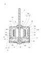
- FIG. 2 is a side sectional view showing the motor 1.
- FIG. 3 is an exploded top perspective view of the motor 1.
- FIG. 4 is an exploded lower perspective view of the motor 1.
- the arrow D indicates the rotation axis direction.
- the motor 1 is a brushless motor. As shown in FIG. 1, the motor 1 has a frame 11, a rotating shaft 2 and a cover 12. The motor 1 has a shape in which a rotation shaft 2 protrudes upward (upward) from a cylindrical housing 10 configured by a frame 11 and a cover 12.
- An opening is provided in a part of the cover 12, and the connector 55 disposed on the lower surface of the substrate 40 (FIG. 2) is exposed through the opening.
- electric power can be supplied to the motor 1 from the outside of the housing 10 of the motor 1 via the connector 55.
- a bearing 9 is disposed at the center of the cover 12 (described later).
- the frame 11 has a cylindrical portion 11 m and a top surface 11 l closing one end of the cylindrical portion 11 m, that is, the upper end.
- the frame 11 roughly has a cup shape or a cylindrical shape with a bottom.
- a cover 12 is attached to the other or lower opening of the frame 11.
- the cylindrical portion of the frame 11 has a circular, cylindrical shape when viewed from above.
- the rotation axis 2 penetrates the top surface 11 l of the frame 11.
- a bearing 8 is held on the top surface 11 l of the frame 11.
- the rotating shaft 2 is supported by a bearing 8.
- the rotation axis 2 is rotatable with respect to the frame 11.
- the rotation axis 2 is disposed substantially perpendicular to the top surface 11 l of the frame 11.
- the rotation axis 2 is located at the center of the cylindrical portion 11 m of the frame 11 in plan view (as viewed from above).
- the rotation shaft 2 protrudes upward from the top surface 11 l of the frame 11 when viewed from the frame 11.
- a hole 11h is formed in the top surface of the frame 11.
- the hole 11 h is used, for example, when the motor 1 is attached to an external device and used.
- a screw or the like can be attached to the hole 11 h.
- a bearing 9 is disposed at the center of the cover 12.
- the bearing 9 is held by the cover 12.
- the rotating shaft 2 is supported by a bearing 9.
- the rotary shaft 2 is rotatably supported relative to the frame 11 by two bearings, an upper bearing 8 and a lower bearing 9.
- the motor 1 has an internal space surrounded by the frame 11 and the cover 12. Various parts are accommodated in the interior space. That is, inside the frame 11, the rotor 2a, the elastic member 15, the stator 20, the substrate 40 and the like are arranged.
- the motor 1 is a so-called inner rotor type motor.
- the annular stator 20 is disposed along the inner circumferential portion 11 a of the cylindrical portion 11 m of the frame 11.
- the stator 20 surrounds the rotating shaft 2.
- the outer peripheral surface of the rotor 2 a (that is, the outer peripheral surface of the magnet 3) is surrounded by the stator 20.
- the rotor 2 a has a magnet 3 and a yoke 4.
- the yoke 4 has a cup shape having a cylindrical portion 4m and a top surface 4l covering the upper end of the cylindrical portion 4m. That is, the yoke 4 has a cylindrical shape having a top surface 4 l. The lower end of the yoke 4 is an opening.
- the yoke 4 may not be cup-shaped, but may be a cylindrical core or the like.
- the planar shape of the magnet 3 is annular.
- the magnet 3 is attached to the magnet 3 with the inner peripheral surface of the magnet 3 facing the outer peripheral side surface of the cylindrical portion of the yoke 4.
- the outer peripheral surface of the magnet 3 is opposed to the inner peripheral surface of the stator core 23 of the stator 20.
- the rotation shaft 2 is disposed substantially perpendicular to the top surface 4 l of the yoke 4.
- the rotation shaft 2 penetrates the top surface 4 l of the yoke 4 and is fitted to the top surface 4 l of the yoke 4. Thereby, the rotating shaft 2 and the rotor 2a are mutually fixed.
- FIG. 5 is a lower exploded perspective view showing the structure of the stator 20 and the substrate 40. As shown in FIG.
- FIG. 5 illustration of patterns of conductor portions on the substrate 40, lands, various circuit elements and the like, and illustration of conductors 27 described later are omitted.
- the stator 20 has a stator core 23, a coil 25 and a resin member 30.
- the motor 1 is a three-phase brushless motor, and the number of slots is nine.
- the stator core 23 (FIG. 2) is configured, for example, by stacking steel plates (not shown).
- the stator core 23 has teeth 23 a extending toward the rotating shaft 2 from the side of the frame 11 (FIG. 2).
- the teeth 23 a face the outer peripheral surface of the magnet 3.
- stator core 23 is divided for each slot of stator 20.
- the present invention is not limited to this, and a plurality of slots may be integrated.
- the resin member 30 is attached to the stator core 23.
- the resin member 30 is an insulating member (insulator) that insulates the coil 25 and the stator core 23. In addition, the resin member 30 insulates the coil 25 and the frame 11.
- the coil 25 is wound around the stator core 23 via the resin member 30. That is, the coil 25 is wound around the resin member 30.
- the resin member 30 is attached to the stator core 23 for each slot, and the coil 25 is wound around the resin member 30.
- the resin member 30 of each slot extends above and below the stator core 23 near the outer periphery of the stator 20.
- a resin member 30 is provided between the coil 25 and the frame 11, and the coil 25 and the frame 11 are insulated.
- the positions of the lower end surfaces 31 of the resin members 30 of the respective slots are substantially the same in the rotational axis direction except for the portions where the convex portions 34 (34a, 34b, 34c) are provided as described later.
- the substrate 40 is disposed on the lower end surface 31 of the resin member 30. That is, the resin member 30 is located between the stator core 23 and the substrate 40 in the rotational axis direction.
- the substrate 40 is provided on the stator 20.
- the substrate 40 is disposed below the stator 20.
- the substrate 40 is disposed on the lower end surface 31 of the resin member 30.
- the substrate 40 has an annular contour whose dimension in the radial direction is smaller than that of the inner circumferential portion 11 a of the cylindrical portion of the frame 11.
- the substrate 40 has a substantially circular plate shape.
- the substrate 40 has an upper surface 40 a and a lower surface 40 b, and an outer peripheral portion 41.
- the upper surface 40 a and the lower surface 40 b are surrounded by the outer peripheral portion 41.
- a hole 42 through which the rotation shaft 2 passes is provided at a substantially central portion of the substrate 40.
- the substrate 40 is disposed in a posture substantially perpendicular to the rotation axis 2. That is, the upper surface 40 a of the substrate 40 is substantially perpendicular to the rotation axis 2.
- the upper surface 40a of the substrate 40 is a surface facing the rotor 2a.
- the substrate 40 is provided with a control circuit for driving the motor 1.
- the substrate 40 applies a drive current to each coil 25 of the motor 1 at a timing according to the rotation of the rotor 2 a to drive the motor 1.
- a sensor 53 is provided on the substrate 40.
- the sensor 53 is a Hall element.
- a sensor 53 is provided for each of the three phases. That is, three sensors 53 are provided.
- the sensor 53 is disposed on the upper surface 40 a of the substrate 40.
- the sensor 53 detects a magnetic field.
- the sensor 53 mainly detects the position of the magnetic pole of the magnet 3. That is, the sensor 53 detects the rotational position of the rotor 2a. As described later, since the sensor 53 is positioned to be at a predetermined position, detection accuracy by the sensor 53 is improved.
- a connector 55 is provided on the lower surface 40 b of the substrate 40.
- the illustration of the specific shape of the connector 55 is omitted.
- the connector 55 connects a power supply line or a signal line from an external device to the control circuit on the substrate 40.
- the elastic member 15 is disposed between the lower surface 40 b of the substrate 40 and the cover 12.
- the elastic member 15 is made of, for example, a resin having elasticity, such as natural rubber or synthetic rubber.
- the elastic member 15 is in contact with the vicinity of the outer peripheral portion 41 of the substrate 40 in a state of being curved in an annular shape.
- the elastic member 15 is compressed between the substrate 40 and the cover 12 in the rotational axis direction more than in a natural state (a state in which no external load is applied).
- a natural state a state in which no external load is applied.
- the substrate 40 is pressed against the stator 20 by the elastic member 15.
- the substrate 40 is fixed in the rotation axis direction in a state of being attached to the stator 20.
- the elastic member 15 is provided with a plurality of recesses 15 b that are recessed in the rotation axis direction. Thereby, compared with the case where the recessed part 15b is not provided, the spring constant of the rotation axis direction of the elastic member 15 is small.
- the substrate 40 is pressed upward by the elastic member 15 with an appropriate amount of force.
- the position of the recess 15 b corresponds to the position on the lower surface 40 b of the substrate 40 where the land, the lead wire, the circuit element and the like are provided.
- the elastic member 15 is not in contact with lands, wires, circuit elements and the like on the lower surface 40 b of the substrate 40.
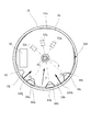
- FIG. 6 is a bottom view showing the mounting structure of the substrate 40 of the motor 1.
- FIG. 6 illustration of patterns of conductors on the substrate 40, lands, various circuit elements and the like is omitted except for a part.
- the motor 1 in a state in which the cover 12 and the elastic member 15 are not attached is shown, and a portion of the stator 20 and the rotor 2a which is hidden behind the substrate 40 is shown by a broken line.
- the sensors 53 (53a, 53b, 53c) on the upper surface 40a of the substrate 40 are shown by broken lines.
- lands 47 As shown in FIG. 6, on the lower surface 40b of the substrate 40, three lands 47 (47a, 47b, 47c) are provided. Three lands 47 are provided corresponding to the three phases of the motor 1. In the present embodiment, the land 47a corresponds to the U phase, the land 47b to the V phase, and the land 47c to the W phase.
- Each land 47 is connected to an end of a conducting wire 27 (27a, 27b, 27c) connected to the coil 25 of the corresponding phase.
- the conducting wire 27a corresponds to the U phase
- the conducting wire 27b to the V phase
- the conducting wire 27c to the W phase.
- the other end (not shown) of the conducting wire 27 of the coil 25 of each phase is connected to a common potential not shown.
- it is connected to a land (not shown) of a common potential provided on the lower surface 40 b of the substrate 40.
- the sensor 53a corresponds to the U phase, the sensor 53b to the V phase, and the sensor 53c to the W phase.
- the three sensors 53 are circumferentially spaced by 40 degrees. That is, the three sensors 53 are arranged in the circumferential direction at the same interval as the interval of the slots in the stator 20 in the circumferential direction.
- Each sensor 53 is disposed at a position overlapping the magnet 3 in the axial direction. That is, each sensor 53 is disposed at a position separated from the rotation axis 2 by substantially the same distance as the radius of the magnet 3.
- the circumferential position of each sensor 53 is positioned by positioning the substrate 40 as described later.
- one common line wiring portion 43 and three concave portions 44 are provided in the outer peripheral portion 41 of the substrate 40.
- the common line wiring portion 43 is a portion provided in a part of the outer peripheral portion 41 and recessed in the radial direction.
- a gap between the common line wiring portion 43 and the inner circumferential portion 11 a of the frame 11 is, for example, a wiring path of the common line.
- each of the three recesses 44 is a radially recessed portion provided in a part of the outer peripheral portion 41. As the rotation shaft 2 is approached, the circumferential dimension of the recess of each recess 44 decreases.
- each recess 44 has a tapered shape in which the dimension in the circumferential direction of the recess of each recess 44 decreases as the rotation shaft 2 is approached. That is, the end of each recess 44 has a contour extending linearly from the outer peripheral portion 41 to the vicinity of the tip portion 44p close to the rotation axis 2, and when viewed from the rotation axis direction, the rotation shaft 2 and the tip portion 44p It has a shape that is symmetrical with respect to a straight line passing through. In other words, each of the recessed portions 44 has a shape in which a fan-shaped portion centered on the vicinity of the tip end portion 44 p is cut away from the outer peripheral portion 41 as viewed roughly.
- a rounded portion (corner radiused portion) is provided at the corner between the contour of the recess 44 and the other part of the outer peripheral portion 41.
- a rounded portion (round corner portion) is also provided between the two fan-shaped radii of the recess 44, that is, the two lines forming the tapered shape of the contour of the recess 44.
- the tip end 44p of the recess 44 is close to the rotation shaft 2.
- the three recesses 44 are provided corresponding to the three phases of the motor 1.
- the recess 44 a corresponds to the U phase
- the recess 44 b to the V phase
- the recess 44 c to the W phase.
- the three recesses 44 are arranged in the circumferential direction at the same interval as the interval of the slots in the stator 20 in the circumferential direction.
- Each recess 44 is disposed at a position corresponding to three slots adjacent in the circumferential direction of the stator 20.
- the three recesses 44 are circumferentially spaced by 40 degrees.
- the recess 44 corresponding to a specific phase is provided in the outer peripheral portion 41 at a position opposite to the sensor 53 corresponding to that phase with respect to the rotational shaft 2.
- the sensor 53 and the recess 44 corresponding to the specific phase are disposed at positions where a distance of 180 degrees is secured in the circumferential direction. That is, the sensor 53a and the recess 44a corresponding to the U phase are arranged at positions separated by 180 degrees in the circumferential direction.
- the sensor 53b and the recess 44b corresponding to the V phase are disposed at positions separated by 180 degrees in the circumferential direction.
- the sensor 53c and the recess 44c corresponding to the W phase are disposed at positions separated by 180 degrees in the circumferential direction.
- the land 47 corresponding to a particular phase is provided in the vicinity of the recess 44 corresponding to that phase.
- Each land 47 is provided in the vicinity of the leading end 44 p of each recess 44.
- a contact portion 49 in contact with the inner peripheral portion 11 a of the frame 11 is provided on the outer peripheral portion 41 of the substrate 40.
- the contact portion 49 is two projecting portions 49 j and 49 k.
- the substrate 40 is attached to the motor 1 with the contact portion 49 in contact with the inner peripheral portion 11 a of the frame 11.
- a part of the inner circumferential portion 11a of the frame 11 is the contact portions 11j and 11k with which the contact portion 49 contacts.
- the inner circumferential portion 11a of the frame 11 has contacted portions 11j and 11k with which the two projecting portions 49j and 49k respectively contact.
- the to-be-contacted parts 11 j and 11 k are inner peripheral surfaces curved along the outer peripheral part 41 of the substrate 40 in the circumferential direction.
- the protrusions 49 j and 49 k are formed to protrude toward the inner peripheral portion 11 a of the frame 11 with respect to the annular contour of the outer peripheral portion 41 of the substrate 40.
- the protrusion 49 j and the protrusion 49 k are spaced apart from each other in the circumferential direction.
- the protrusions 49 j and 49 k are unevenly distributed in the circumferential direction.
- the protrusions 49 j and 49 k and the recess 44 are unevenly distributed in regions different from each other in the circumferential direction. That is, the protrusions 49 j and 49 k are at positions relatively away from the three recesses 44 in the circumferential direction.
- the protrusion 49 j and the protrusion 49 k are disposed at an interval of, for example, about 80 degrees in the circumferential direction.
- the recess 44 c closest to the protrusion 49 j and the protrusion 49 j are disposed at an interval of, for example, 80 degrees in the circumferential direction.
- the concave portion 44a closest to the projecting portion 49k and the projecting portion 49k are arranged at an interval of, for example, 120 degrees in the circumferential direction.
- the resin member 30 is provided with three convex portions 34 (34 a, 34 b, 34 c) extending in the rotation axis direction.
- the three projections 34 are provided on the resin member 30 of the three slots and extend downward.
- a step surface 33 is provided at substantially the same position as the lower end surface 31 of the other resin member 30 in the rotational axis direction.
- the convex portion 34 is a projecting portion that protrudes downward from the step surface 33.
- the three convex portions 34 are provided at positions corresponding to the three concave portions 44 of the substrate 40. That is, the convex portions 34 are provided on the resin members 30 of three slots adjacent in the circumferential direction.
- the outer circumferential surface of each convex portion 34 has a curved surface along the inner circumferential portion 11a of the frame 11, a plane facing inward in the radial direction, and two planes connecting the both and facing in both the circumferential direction and the radial direction. doing. Among these, assuming that the curved surface along the inner peripheral portion 11 a of the frame 11 is a plane, it can be said that the convex portion 34 has a trapezoidal outer surface as viewed from the rotation axis direction.
- the convex portion 34 has a substantially trapezoidal shape having a long side slightly curved along the inner peripheral portion 11 a of the frame 11 in a plan view.
- the radial dimension of the projection 34 is slightly smaller than the radial dimension of the recess 44.
- each convex portion 34 has a tapered shape in which the dimension in the circumferential direction decreases as the rotation axis 2 is approached. That is, the two outer side surfaces 35 of each convex portion 34 have a contour extending linearly from a curved surface along the inner peripheral portion 11 a of the frame 11 to a plane facing inward in the radial direction when viewed from the rotation axis direction.
- the convex portion 34 has a shape that is symmetrical with respect to a straight line passing through the rotation axis 2 when viewed from the rotation axis direction.
- the convex portion 34 is inside the concave portion 44.
- the convex portion 34 has two outer side surfaces 35 along the edge of the concave portion 44.
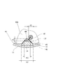
- FIG. 7 is an end view showing a schematic structure of a portion where the recess 44 is provided.
- FIG. 8 is a partially enlarged view showing a portion provided with the recess 44 as viewed from below.
- the lower end portion of the convex portion 34 is below the lower surface 40 b of the substrate 40.
- the inner end of the recess 44 is inside the position of the outer peripheral portion 41 of the substrate 40 in a portion where the recess 44 is not provided. Since the convex portion 34 is inside the concave portion 44, the circumferential displacement of the substrate 40 is restricted by the convex portion 34. That is, when the convex portion 34 is positioned inside the concave portion 44, the circumferential position of the substrate 40 with respect to the stator 20 is regulated.
- the convex portion 34 serves as a positioning portion of the substrate 40.
- the substrate 40 is held by the projections 34 so as not to rotate.
- the opening width w2 in the radial direction near the outer peripheral portion 41 of the recess 44 (here, the width in the direction perpendicular to the radial direction when viewed from the rotation axis direction) is And the width w1 of the convex portion 34 in a portion close to the rotation axis 2.
- a portion close to the rotation axis 2 of the convex portion 34 is in contact with or close to the edge of the concave portion 44 inside the concave portion 44.
- a gap 45 an example of a non-occupied region surrounded by the outer surface of the protrusion 34 and the edge of the recess 44 is formed.
- An area inside the concave portion 44 and close to the frame 11 is an occupied area 46 occupied by the convex portion 34. Since the outer side surface 35 of the projection 34 is along the edge of the recess 44, the occupied region 46 fills most of the region of the recess 44 near the frame 11 when viewed from the rotational axis direction. In the present embodiment, as viewed in the rotation axis direction, the area of the occupied region 46 is larger than the area of the gap 45 not occupied by the convex portion 34 in the region inside the concave portion 44.
- the width of the gap 45 is smaller than the width of the land 47.
- the radial width w3 of the gap 45 is smaller than the width d1 of the land 47. That is, the size of the gap 45 connecting the lower space of the substrate 40 and the upper space of the substrate 40 is relatively small.
- the conducting wire 27 extends from the lower surface 40 b of the substrate 40 through the gap 45 toward the stator 20.
- the end of the conductor 27 is electrically connected to the land 47 by a conductive member 48.
- the conductive member 48 is, for example, a solder.
- the outer surface 35 of the projection 34 is along the edge of the recess 44, the occupied area 46 is relatively large, and the gap 45 is relatively narrow. Therefore, the foreign matter is prevented from entering the space above the substrate 40.
- the conductive member 48 becomes a lump having a width as large as the width of the land 47. Since the width of the gap 45 is smaller than the width of the land 47 in the radial direction, the conductive member 48 may fall off the land 47 even when, for example, the conductor 27 is connected to the land 47. The conductive member 48 which has fallen is prevented from entering the space above the substrate 40.
- the solder As the conductive member 48, when the lead 27 is soldered to the land 47, even if a so-called solder ball is generated without the solder joining the land 47, the solder ball is higher than the substrate 40. It is prevented from entering the space. Therefore, the motor 1 can be manufactured more easily.
- the contact portion 49 is provided on the outer peripheral portion 41 of the substrate 40, and the contact portion 49 contacts the inner peripheral portion 11 a of the frame 11 to make the substrate 40 in the radial direction. It is energized.
- FIG. 9 is a bottom view showing the relationship between the substrate 40, the frame 11, and the convex portion 34. As shown in FIG.
- FIG. 9 the rotation axis 2, the substrate 40, the frame 11, and the resin member 30 are shown.
- the two-dot chain line virtually indicates the position of the substrate 40 when the contact portion 49 and the frame 11 do not contact with each other.
- the contact portion 49 of the substrate 40 contacts the contact portions 11 j and 11 k of the inner peripheral portion 11 a of the frame 11, whereby the biasing force of the frame 11 is exerted.
- (Indicated by arrows F1 and F2) act on the substrate 40.
- An arrow F1 indicates a biasing force generated by the projection 49j coming into contact with the contact portion 11j.
- An arrow F2 indicates a biasing force generated by the protrusion 49k coming into contact with the contact portion 11k. Each biasing force acts in the radial direction.
- the biasing force acting on the substrate 40 due to the provision of the two projecting portions 49 j and 49 k is a combination of the two biasing forces described above (indicated by the arrow F). Since the protrusions 49j and 49k are at positions relatively separated from the three recesses 44 in the circumferential direction, the substrate 40 is provided with the recesses 44 from the side on which the protrusions 49j and 49k are provided. The biasing force acts on the That is, the substrate 40 is biased by the frame 11, and the concave portion 44 is pushed toward the convex portion 34 of the resin member 30.
- the protrusions 49 j and 49 k protrude from the annular contour of the outer peripheral portion 41, and the protrusions 49 j and 49 k are of the frame 11. Since the inner peripheral portion 11a is in contact, the substrate 40 is displaced in the direction away from the contacted portions 11j and 11k. That is, the substrate 40 is radially biased toward a part of the frame 11.
- the substrate 40 is biased in the radial direction by the contact portion 49 and the contact portions 11 j and 11 k coming into contact with each other.
- the position of the sensor 53 on the substrate 40 is preset so that the sensor 53 is disposed at an appropriate position in a state where the substrate 40 is biased. Therefore, the sensor 53 can be disposed at a desired position.
- the position of the sensor 53 is from the desired position. Because of misalignment, the sensor 53 may not be provided at an appropriate position.
- the sensor 53 since the substrate 40 can be positioned, the sensor 53 can be disposed at a desired position.
- the sensor 53 which is a Hall element can be disposed on the magnet 3 of the rotor 2a, and the sensor 53 can detect the magnetic flux of the magnet 3 efficiently. Since the detection accuracy of the rotation speed of the motor 1 can be improved, the performance of the motor 1 can be improved.
- the substrate 40 is biased by the frame 11 and pressed against the convex portion 34 of the resin member 30. Therefore, the substrate 40 can be positioned with respect to the stator 20.
- the convex portion 34 is located inside the concave portion 44 of the substrate 40. Therefore, the circumferential position of the substrate 40 is positioned with respect to the stator 20.
- the recess 44 has a tapered shape in which the circumferential dimension of the recess of each recess 44 decreases as the rotation shaft 2 is approached. Therefore, the convex portion 34 can be positioned inside the concave portion 44, and the substrate 40 can be easily disposed below the stator 20. Further, since the substrate 40 is biased toward the convex portion 34 in a state where a part of the convex portion 34 is in contact with the edge portion of the concave portion 44, the circumferential position of the substrate 40 can be positioned more accurately. Can. Moreover, in the first embodiment, the convex portion 34 also has a tapered shape corresponding to the concave portion 44. Therefore, the radial and circumferential positions of the substrate 40 are positioned in a state where the substrate 40 is biased and the concave portion 44 is pushed into the convex portion 34.
- the resin member 30 In the stator 20, in the state where the coil 25 is wound around the resin member 30, the resin member 30 is slightly deformed as compared with the case where the coil 25 is not wound. Since the coil 25 is wound, the lower end portion of the resin member 30 is slightly bent toward the rotation shaft 2 and curved. By urging the substrate 40 in a direction substantially opposite to the direction of deformation with respect to the resin member 30 thus bent, the elasticity of the resin member 30 is utilized to cause rattling and the like. The position of the substrate 40 can be positioned firmly by making it difficult.
- the recess 44c closest to the protrusion 49j and the protrusion 49j are arranged at an interval of 80 degrees in the circumferential direction, and the recess 44a and protrusion closest to the protrusion 49k
- the portions 49 k are spaced apart by 120 degrees in the circumferential direction. That is, when viewed from the rotation shaft 2, the direction in which the three recesses 44 are provided and the direction in which the substrate 40 is biased are slightly deviated.
- the substrate 40 is biased toward the space between the recess 44 a and the recess 44 b among the three recesses 44 arranged at equal intervals in the circumferential direction, as viewed from the rotation shaft 2.
- the protrusion 34 is an edge of the recess 44.
- the substrate 40 can be positioned in contact with at least a part.
- the substrate 40 When the projecting portion 49k comes into contact with the contact portions 11j and 11k of the frame 11, the substrate 40 is urged in the radial direction and the circumferential direction, or in the circumferential direction. It is also good.
- the contact surface between the protrusion 49 and the frame 11 is inclined with respect to the surface perpendicular to the radial direction to apply a force for biasing the substrate 40 in the circumferential direction, and the convex portion 34 It may be pushed in.
- the number and shape of the protrusions 49k, the number and shape of the recesses 44, the position of the protrusions 49k, and the like are not limited thereto, and various aspects can be made.
- FIG. 10 is a bottom view showing a configuration of a substrate 140 according to a first modified example of the first embodiment.
- the substrate 140 according to the present modification is shown together with the rotary shaft 2, the frame 11, and the resin member 30 in the same manner as in FIG. 9 described above.
- the same components as those of the first embodiment described above are denoted by the same reference numerals.
- the substrate 140 has contact portions 149 (protrusions 149j, protrusions 149k) different in position from the contact portions 49 of the substrate 40 described above.
- the other configuration of the substrate 140 is similar to that of the substrate 40 described above. That is, the protrusion 149j is disposed at an interval of about 110 degrees in the circumferential direction with the recess 44c closest to the protrusion 149j, and the protrusion 149k is located around the recess 44a closest to the protrusion 149k. In the direction, they are spaced apart by about 90 degrees. That is, when viewed from the rotation shaft 2, the direction in which the three recesses 44 are provided and the direction in which the substrate 140 is biased are slightly deviated.
- the substrate 140 is biased toward the space between the recess 44 b and the recess 44 c among the three recesses 44 as viewed from the rotation shaft 2. Even in such a positional relationship between the protrusions 149 j and 149 k and the recess 44, the substrate 140 can be positioned in the same manner as described above.
- FIG. 11 is a bottom view showing a configuration of a substrate 240 according to a second modified example of the first embodiment.
- the substrate 240 according to the present modification is shown together with the rotating shaft 2, the frame 11, and the resin member 30 in the same manner as in FIG. 9 described above.
- the same components as those of the first embodiment described above are denoted by the same reference numerals.
- the substrate 240 has only one contact portion 249 (protrusion portion 249j).
- the other configuration of the substrate 240 is similar to that of the substrate 40 described above.
- the protrusion 249 j is disposed at an interval of 80 degrees in the circumferential direction from the recess 44 c closest to the protrusion 249 j. Therefore, in the present modification, a biasing force is exerted on the substrate 240 from the protrusion 249 j toward the rotation shaft 2 (indicated by an arrow F 1).
- the biasing force includes a component that biases the substrate 240 in the direction in which the recess 44 c is separated from the protrusion 34 c.
- the substrate 240 is slightly displaced in the circumferential direction, and the concave portion 44c is pushed into the convex portion 34c. Therefore, the substrate 240 can be positioned in the same manner as described above.
- FIG. 12 is a bottom view showing the configuration of a frame 311 and a substrate 340 according to a third modification of the first embodiment.
- FIG. 12 the substrate 340 and the frame 311 according to the present modification are shown together with the rotation shaft 2 and the resin member 30 in the same manner as in FIG. 9 described above.
- the same components as those of the first embodiment described above are denoted by the same reference numerals.
- the contact portions 311j and 311k of the frame 311 are protrusions.
- two projecting portions 311j and 311k are provided on the inner circumferential portion 11a of the frame 311.
- the protrusions 311 j and 311 k are provided on the contact portion.
- the protrusions 311 j and 311 k protrude toward the outer peripheral portion 41 of the substrate 340 in the radial direction.
- the contact portions 349j and 349k are side surfaces of the outer peripheral portion 41 of the substrate 340, which are curved along the inner peripheral portion 11a of the frame 311 in the circumferential direction.
- the projecting portions 311 j and 311 k may be formed, for example, by pushing a part of the frame 311 in the radial direction, or by sticking a small piece or the like in a projecting shape to the inner peripheral portion 11 a of the frame 311. It may be done.
- the protruding portions 311 j and 311 k are formed so as to protrude toward the outer peripheral portion 41 of the substrate 340 with respect to the annular contour of the inner peripheral portion 11 a of the frame 311.
- the protrusion 311 j and the protrusion 311 k are spaced apart from each other in the circumferential direction.
- the protrusions 311 j and 311 k are unevenly distributed in the circumferential direction.
- the contact portions 349j and 349k and the recess 44 are unevenly distributed in different regions in the circumferential direction. That is, the contact portions 349 j and 349 k are located at positions relatively away from the three recesses 44 in the circumferential direction.
- the protruding portion 311j and the protruding portion 311k are arranged at an interval of, for example, about 80 degrees in the circumferential direction.
- the recess 44 c closest to the protrusion 49 j and the protrusion 49 j are disposed at an interval of, for example, 80 degrees in the circumferential direction.
- the concave portion 44a closest to the projecting portion 49k and the projecting portion 49k are arranged at an interval of, for example, 120 degrees in the circumferential direction.
- the protrusions 311 j and 311 k contacting the substrate 340 may be provided on the frame 311 side, and the substrate 340 may be biased by contacting the protrusions 311 j and 311 k.
- the sensor 53 can be disposed as in the above-described embodiment.
- frame 311 is not restricted to two, One may be sufficient and three or more may be sufficient.
- FIG. 13 is a bottom view showing a configuration of a frame 311 and a substrate 440 according to a fourth modified example of the first embodiment.
- FIG. 13 the substrate 440 and the frame 411 according to the present modification are shown together with the rotation shaft 2 and the resin member 30 in the same manner as in FIG. 9 described above.
- the same components as those of the first embodiment and the modifications described above are denoted by the same reference numerals.
- protrusions may be formed on both the contact portion and the contact portion.
- a frame 311 similar to the third modified example is provided.
- the frame 311 is provided with contact portions 311j and 311k, which are protrusions, and the substrate 440 is provided with contact portions 349j and 349k similar to the substrate 340.
- a contact portion 449i which is a projecting portion protruding toward the inner circumferential portion 11a of the frame 311 in the radial direction, is provided on the substrate 440, and one of the inner circumferential portion 11a of the frame 311 contacting the contact portion 449i.
- the part is a contacted part 411i.
- a first protrusion 449i protruding toward the frame 311 and portions 349j and 349k with which the second protrusions 311j and 311k of the frame 311 contact are provided as contact portions.
- second protrusions 311j and 311k protruding toward the substrate 440, and a portion 411i in contact with the first protrusion 449i of the substrate 440 are provided as the to-be-contacted portions.
- the first protrusion 449i of the contact portion and the second protrusions 311j and 311k of the contact portion are at mutually different positions in the circumferential direction.
- the first protrusion 449i is provided between the second protrusions 311j and 311k.
- the second protrusions 311j, the first protrusions 449i, and the second protrusions 311k are arranged in this order in the circumferential direction at substantially equal intervals in the counterclockwise direction.
- the substrate 440 contacts the frame 311 at three points. At each contact point, a biasing force acts on the substrate 440 by the frame 311 (arrows F1, F2, F3), and the substrate 440 is biased by a combined force of the biasing forces as shown by the arrow F. Therefore, the sensor 53 can be disposed as in the first embodiment.
- FIG. 14 is a bottom view showing the configuration of a substrate 540 according to a fifth modification of the first embodiment.
- FIG. 14 the substrate 540 according to the present modification is shown together with the rotation shaft 2, the frame 11, and the resin member 30 in the same manner as in FIG. 9 described above.
- the same components as those of the first embodiment and the modifications described above are denoted by the same reference numerals.
- the substrate 540 has contact portions 549 (protrusions 549 j and protrusions 549 k) different in position from the contact portions 49 of the substrate 40 described above.
- the other configuration of the substrate 540 is similar to that of the substrate 40 described above.
- the contact portion 549 is provided on the side where the three recesses 44 are provided.
- the protrusion 549 j is provided on the outer peripheral portion 41 between the common line wiring portion 43 and the recess 44 a.
- the protrusion 549 k is provided on the outer peripheral portion 41 between the recess 44 b and the recess 44 c.
- the protrusions 549 j and 549 k are formed to protrude toward the inner peripheral portion 11 a of the frame 11 with respect to the annular contour of the outer peripheral portion 41 of the substrate 540.
- the substrate 540 is biased by the frame 11 and pressed against the inner circumferential portion 11 a of the frame 11.
- the substrate 540 is biased toward the portion of the frame 11 opposite to the portion where the convex portion 34 is in proximity, and a part of the outer peripheral portion 41 of the substrate 540 is the inner peripheral portion 11 a of the frame 11. It is positioned with respect to the frame 11 in a contact state.
- the substrate 540 is located at a position offset with respect to the frame 11.
- the senor 53 can be disposed at a desired position. Further, as shown in FIG. 14, the convex portion 34 of the resin member 30 is present inside the concave portion 44 of the substrate 540 even in a state where the substrate 540 is biased. Therefore, the circumferential position of the substrate 540 is positioned.
- the convex portion 34 of the resin member 30 may have another shape such as a cylindrical shape.
- the basic configuration of the motor 1 in the second embodiment is the same as that in the first embodiment, and therefore the description thereof will not be repeated.
- the same components as those of the first embodiment will be described with the same reference numerals.
- the second embodiment differs from the first embodiment in that a conductor guiding portion 736 for wiring the conductor 27 toward the land 47 is formed at the lower end portion of the convex portion 34. There is.
- FIG. 15 is a lower exploded perspective view showing the structure of the stator 20 and the substrate 40 according to the second embodiment.
- FIG. 16 is a bottom view showing the mounting structure of the substrate 40 of the motor 1 according to the second embodiment.
- FIG. 17 is an end view showing a schematic structure of a portion where the convex portion 34 according to the second embodiment is provided.
- FIG. 18 is a perspective view showing a portion where the recess 44 is provided.
- FIG. 15 is described in the same manner as FIG. 5 described above.
- FIG. 16 is described in the same manner as FIG. 6 described above.
- FIG. 17 is described in the same manner as FIG. 7 described above.
- the illustration of the conductor 27 is omitted.
- the illustration of the conductive member 48 is omitted except for FIG.
- a convex portion 34 is provided in a part of the resin member 730 of the stator 20, similarly to the resin member 30 according to the first embodiment.
- the convex portions 34 are provided at three locations, and are respectively disposed inside the concave portions 44 of the substrate 40.
- the three lands 47 provided on the lower surface 40 b of the substrate 40 are provided circumferentially adjacent to the three recesses 44 respectively. That is, the convex portions 34 and the lands 47 corresponding to the respective phases are arranged in the circumferential direction.
- Each of the three convex portions 34 is provided with a wire guide portion 736.
- the wire guide portion 736 protrudes downward from the lower end surface of the convex portion 34.
- the wire guide portion 736 has a first protrusion 737 and a second protrusion 738.
- the first protrusion 737 is provided near the inner circumferential portion 11 a of the frame 11.
- the first protrusion 737 has a wall shape extending in the circumferential direction.
- the second protrusion 738 is provided radially inward of the first protrusion 737 (a position close to the rotation axis 2).
- the second protrusion 738 has a columnar shape whose circumferential length is shorter than that of the first protrusion 737.
- the second protrusion 738 has a rounded side circumferential surface.
- the second protrusion 738 has, for example, a columnar shape whose cross section perpendicular to the rotation axis direction is an elliptical shape or a track shape.
- FIG. 17 A cross section passing through the first protrusion 737 and the second protrusion 738 is shown in FIG. As shown in FIG. 17, the second protrusions 738 are provided radially spaced from the first protrusions 737.
- the wire guide portion 736 is formed with a groove-like recess 739 having the first protrusion 737 and the second protrusion 738 as side walls.
- the recess 739 extends in the circumferential direction.
- the radial dimension of the recess 739 is slightly larger than the thickness of the conducting wire 27.
- the conductor 27 drawn through the gap 45 from the upper surface 40 a side to the lower surface 40 b side of the substrate 40 (from the stator 20 to the lower surface 40 b side)
- the wire is entangled in the wire guide portion 736 so as to pass through the upper side, and is wired toward the land 47 adjacent to the wire guide portion 736 in the circumferential direction. That is, the conducting wire 27 is wired such that a part of the conducting wire 27 is sandwiched by the recess 739, and is guided to the land 47. Then, the land 47 is connected using the conductive member 48.
- the conducting wire 27 is tangled in the conducting wire guide portion 736, it is difficult for the force and vibration transmitted to the conducting wire 27 to be transmitted to the connecting portion between the conducting wire 27 and the land 47. . Therefore, the reliability of the connection between the conductor 27 and the land 47 can be enhanced. In addition, even if the motor 1 vibrates, it is possible to prevent the lead 27 from coming into contact with the stator 20, the substrate 40, and the like to be disconnected.
- the wire 27 can be connected to the land 47 in a state where the wire 27 is guided to the land 47 by the wire guide portion 736. Therefore, the motor 1 can be easily manufactured.
- the second protrusion 738 has a circumferential dimension smaller than that of the first protrusion 737. Therefore, the wire 27 drawn downward from the gap 45 located inside the second protrusion 738 can be easily entangled in the recess 739. Further, even if the position of the land 47 is slightly closer to the rotation axis 2 than the position of the recess 739, the conducting wire 27 passing through the recess 739 can be easily guided inward to the land 47. Since the side peripheral surface of the second protrusion 738 is rounded, the bending radius of the lead 27 to be wired can be easily maintained at a certain level or more, and the lead 27 can be prevented from being damaged.
- the motor may be configured by appropriately combining a part of the configuration of the first embodiment including the modified example described above with a configuration of a part of the second embodiment.
- the number of slots of the stator, the configuration of the resin member, the shape and configuration of the substrate, and the like are not limited to the above-described embodiment.
- the type of motor is not limited. For example, it may be a brushless motor or another motor.
Landscapes
- Engineering & Computer Science (AREA)
- Power Engineering (AREA)
- Microelectronics & Electronic Packaging (AREA)
- Motor Or Generator Frames (AREA)
Abstract
Provided is a motor with which it is possible to dispose a sensor at a desired position. The motor is provided with a frame (11), a rotor, a stator, a substrate (40) provided to the stator, and a sensor (53) provided to the substrate (40). The substrate (40) has a surface facing the rotor, and an outer peripheral part (41). The outer peripheral part (41) of the substrate (40) is provided with a contact part (49) coming into contact with the inner peripheral part (11a) of the frame (11). The inner peripheral part (11a) of the frame (11) is provided with contacted parts (11j), (11k) coming into contact with the outer peripheral part (41) of the substrate (40). Either, or both of, the contact part (49) and/or the contacted parts (11j)(11k) is provided with a projecting part (49j), (49k) projecting towards the other of the contact part (49) and/or the contacted parts (11j)(11k).
Description
この発明は、モータに関し、特に、センサが設けられている基板を有するモータに関する。
The present invention relates to a motor, and more particularly to a motor having a substrate provided with a sensor.
例えばブラシレスモータ等のモータにおいては、センサが設けられている基板を有するものがある。
For example, some motors such as brushless motors have a substrate provided with a sensor.
なお、下記特許文献1には、固定子鉄心に設けられる端面絶縁部の基板保持部に駆動用回路基板が係合する構造を有する、モータの駆動用回路基板の保持装置が開示されている。
Patent Document 1 below discloses a motor driving circuit board holding device having a structure in which a driving circuit board is engaged with a board holding portion of an end surface insulating portion provided on a stator core.
この発明は、所望の位置にセンサを配置することができるモータを提供することを目的としている。
An object of the present invention is to provide a motor capable of arranging a sensor at a desired position.
上記目的を達成するためこの発明のある局面に従うと、モータは、フレームと、ロータと、ステータと、ステータに設けられた基板と、基板に設けられたセンサとを備え、基板は、ロータに対向する面と、外周部とを有し、基板の外周部には、フレームの内周部に接触する接触部が設けられ、フレームの内周部には、基板の外周部に接触する被接触部が設けられ、接触部及び被接触部の少なくとも一方には、他方に向かって突出する突出部が設けられている。
In order to achieve the above object, according to an aspect of the present invention, a motor includes a frame, a rotor, a stator, a substrate provided on the stator, and a sensor provided on the substrate, the substrate facing the rotor And an outer peripheral portion, the outer peripheral portion of the substrate is provided with a contact portion which contacts the inner peripheral portion of the frame, and the inner peripheral portion of the frame is a contact portion which contacts the outer peripheral portion of the substrate Is provided, and at least one of the contact portion and the contact portion is provided with a protrusion projecting toward the other.
好ましくは、突出部は、一方が設けられている基板の外周部又はフレームの内周部が有する環状の輪郭に対して、他方側に突出する。
Preferably, the protrusion protrudes on the other side with respect to the annular contour of the outer periphery of the substrate on which one is provided or the inner periphery of the frame.
好ましくは、被接触部に接触した接触部は、径方向かつ/又は周方向に付勢されている。
Preferably, the contact portion in contact with the contact portion is biased radially and / or circumferentially.
好ましくは、基板は、フレームの一部に向けて径方向に偏った位置にある。
Preferably, the substrate is at a radially biased position towards a portion of the frame.
好ましくは、一方は、突出部を複数有し、複数の突出部は、周方向において偏在している。
Preferably, one has a plurality of protrusions, and the plurality of protrusions are unevenly distributed in the circumferential direction.
好ましくは、ステータは、ステータコアと、樹脂部材とを有し、樹脂部材は、回転軸方向において、ステータコアと基板との間にあり、基板の外周部は、径方向に凹む凹部を備え、樹脂部材は、回転軸方向に延在する凸部を備え、凹部の内側に凸部がある。
Preferably, the stator has a stator core and a resin member, and the resin member is between the stator core and the substrate in the rotational axis direction, and the outer peripheral portion of the substrate is provided with a recess recessed in the radial direction Has a protrusion extending in the rotational axis direction, and the protrusion is inside the recess.
好ましくは、樹脂部材は、ステータコアに取り付けられており、凸部は、基板の位置決め部となっている。
Preferably, the resin member is attached to the stator core, and the convex portion is a positioning portion of the substrate.
好ましくは、接触部と凹部とは、周方向において互いに異なる領域に偏在している。
Preferably, the contact portion and the recess are unevenly distributed in different regions in the circumferential direction.
好ましくは、接触部に設けられており、被接触部は、周方向において、基板の外周部に沿って湾曲した内周面である。
Preferably, the contact portion is provided on the contact portion, and the contact portion is an inner peripheral surface curved along the outer peripheral portion of the substrate in the circumferential direction.
好ましくは、被接触部に設けられており、突出部は、径方向において、基板の外周部に向かって突出している。
Preferably, the protrusion is provided in the contact portion, and the protrusion protrudes in the radial direction toward the outer periphery of the substrate.
好ましくは、接触部は、周方向においてフレームの内周部に沿って湾曲した、基板の外周部の側面である。
Preferably, the contact portion is a side surface of the outer peripheral portion of the substrate which is curved along the inner peripheral portion of the frame in the circumferential direction.
好ましくは、接触部と被接触部とは、周方向において互いに異なる位置にあり、接触部は、径方向において、フレームの内周部に向かって突出する第1突出部を有し、被接触部は、径方向において、基板の外周部に向かって突出する第2突出部を有する。
Preferably, the contact portion and the contact portion are at mutually different positions in the circumferential direction, and the contact portion has a first protrusion projecting toward the inner circumferential portion of the frame in the radial direction, and the contact portion Has a second protrusion projecting toward the outer periphery of the substrate in the radial direction.
これらの発明に従うと、所望の位置にセンサを配置することができるモータを提供することができる。
According to these inventions, it is possible to provide a motor capable of arranging a sensor at a desired position.
以下、本発明の実施の形態におけるモータについて説明する。
Hereinafter, the motor in the embodiment of the present invention will be described.
以下の説明において、モータの回転軸に平行な方向を、回転軸方向ということがある。また、回転軸に対して垂直な方向を、径方向ということがある。また、回転軸を中心に回転する方向を、周方向ということがある。また、回転軸方向を、上下方向ということがある(モータのハウジングから見て回転軸が突出している方向が上方向)。また、回転軸に対して垂直な平面を、水平面ということがある。ここでいう「上下」、「上」、「下」、「水平」等は、モータのみに着目したときに便宜上採用する示し方であって、そのモータが搭載される機器における方向や、そのモータが使用される姿勢について、何ら限定するものではない。
In the following description, the direction parallel to the rotation axis of the motor may be referred to as the rotation axis direction. Also, a direction perpendicular to the rotation axis may be referred to as a radial direction. Moreover, the direction which rotates centering on a rotating shaft may be called circumferential direction. Also, the direction of the rotation axis may be referred to as the vertical direction (the direction in which the rotation axis protrudes from the housing of the motor is upward). Also, a plane perpendicular to the rotation axis may be referred to as a horizontal plane. Here, “upper and lower”, “upper”, “lower”, “horizontal”, etc. are the methods adopted for convenience when focusing on only the motor, and the direction in the device on which the motor is mounted and the motor There is no limitation on the posture in which is used.
[第1の実施の形態]
First Embodiment
図1は、本発明の第1の実施の形態に係るモータ1を示す斜視図である。図2は、モータ1を示す側断面図である。図3は、モータ1の分解上方斜視図である。図4は、モータ1の分解下方斜視図である。
FIG. 1 is a perspective view showing a motor 1 according to a first embodiment of the present invention. FIG. 2 is a side sectional view showing the motor 1. FIG. 3 is an exploded top perspective view of the motor 1. FIG. 4 is an exploded lower perspective view of the motor 1.
以下の図において、矢印Dは、回転軸方向を示す。
In the following figures, the arrow D indicates the rotation axis direction.
モータ1は、ブラシレスモータである。図1に示されるように、モータ1は、フレーム11と、回転軸2と、カバー12とを有している。モータ1は、フレーム11とカバー12とで構成される円柱状のハウジング10から、回転軸2が上方向(上方)に突き出た形状を有している。
The motor 1 is a brushless motor. As shown in FIG. 1, the motor 1 has a frame 11, a rotating shaft 2 and a cover 12. The motor 1 has a shape in which a rotation shaft 2 protrudes upward (upward) from a cylindrical housing 10 configured by a frame 11 and a cover 12.
なお、カバー12の一部には開口部が設けられており、開口部を通して、基板40(図2)の下側の面に配置されたコネクタ55が露出するように構成されている。これにより、コネクタ55を介して、モータ1のハウジング10の外部から、モータ1に電力を供給することができるようになっている。カバー12の中央部には、軸受9が配置されている(後述)。
An opening is provided in a part of the cover 12, and the connector 55 disposed on the lower surface of the substrate 40 (FIG. 2) is exposed through the opening. As a result, electric power can be supplied to the motor 1 from the outside of the housing 10 of the motor 1 via the connector 55. A bearing 9 is disposed at the center of the cover 12 (described later).
図2に示されるように、フレーム11は、筒部11mと、筒部11mの一端すなわち上端を塞ぐ天面11lとを有している。フレーム11は、大まかに、カップ形状すなわち底がある筒形状を有している。フレーム11の他方の開口部すなわち下の開口部には、カバー12が取り付けられている。フレーム11の筒部は、上方から見て円形の、円筒形状を有する。
As shown in FIG. 2, the frame 11 has a cylindrical portion 11 m and a top surface 11 l closing one end of the cylindrical portion 11 m, that is, the upper end. The frame 11 roughly has a cup shape or a cylindrical shape with a bottom. A cover 12 is attached to the other or lower opening of the frame 11. The cylindrical portion of the frame 11 has a circular, cylindrical shape when viewed from above.
回転軸2は、フレーム11の天面11lを貫通している。フレーム11の天面11lには軸受8が保持されている。回転軸2は、軸受8により支持されている。回転軸2は、フレーム11に対して回転可能である。回転軸2は、フレーム11の天面11lに対して略垂直に配置されている。回転軸2は、平面視で(上から見て)、フレーム11の筒部11mの中央に位置している。回転軸2は、フレーム11から見て、フレーム11の天面11lから上方に突出している。
The rotation axis 2 penetrates the top surface 11 l of the frame 11. A bearing 8 is held on the top surface 11 l of the frame 11. The rotating shaft 2 is supported by a bearing 8. The rotation axis 2 is rotatable with respect to the frame 11. The rotation axis 2 is disposed substantially perpendicular to the top surface 11 l of the frame 11. The rotation axis 2 is located at the center of the cylindrical portion 11 m of the frame 11 in plan view (as viewed from above). The rotation shaft 2 protrudes upward from the top surface 11 l of the frame 11 when viewed from the frame 11.
フレーム11の天面には、孔部11hが形成されている。孔部11hは、例えば、モータ1を外部の装置に取り付けて用いる場合等に用いられる。例えば、孔部11hには、ねじ等を取り付けられる。
In the top surface of the frame 11, a hole 11h is formed. The hole 11 h is used, for example, when the motor 1 is attached to an external device and used. For example, a screw or the like can be attached to the hole 11 h.
カバー12の中央部には、軸受9が配置されている。軸受9は、カバー12に保持されている。回転軸2は、軸受9により支持されている。回転軸2は、上側の軸受8と下側の軸受9との2つの軸受によって、フレーム11に対して、回転可能に支持されている。
A bearing 9 is disposed at the center of the cover 12. The bearing 9 is held by the cover 12. The rotating shaft 2 is supported by a bearing 9. The rotary shaft 2 is rotatably supported relative to the frame 11 by two bearings, an upper bearing 8 and a lower bearing 9.
図2に示されるように、モータ1は、フレーム11とカバー12とで囲まれた内部空間を有している。内部空間には、種々の部品が収容されている。すなわち、フレーム11の内側には、ロータ2a、弾性部材15、ステータ20、及び基板40などが配置されている。
As shown in FIG. 2, the motor 1 has an internal space surrounded by the frame 11 and the cover 12. Various parts are accommodated in the interior space. That is, inside the frame 11, the rotor 2a, the elastic member 15, the stator 20, the substrate 40 and the like are arranged.
モータ1は、いわゆるインナーロータ型モータである。環状のステータ20は、フレーム11の筒部11mの内周部11aに沿って配置されている。ステータ20は、回転軸2を囲んでいる。ロータ2aの外周面(すなわち、磁石3の外周面)は、ステータ20に囲まれている。
The motor 1 is a so-called inner rotor type motor. The annular stator 20 is disposed along the inner circumferential portion 11 a of the cylindrical portion 11 m of the frame 11. The stator 20 surrounds the rotating shaft 2. The outer peripheral surface of the rotor 2 a (that is, the outer peripheral surface of the magnet 3) is surrounded by the stator 20.
ロータ2aは、磁石3と、ヨーク4とを有している。
The rotor 2 a has a magnet 3 and a yoke 4.
本実施の形態において、ヨーク4は、筒部4mと筒部4mの上端を覆う天面4lとを有するカップ形状を有している。すなわち、ヨーク4は、天面4lを有する筒形状を有している。ヨーク4の下端は開口部となっている。なお、ヨーク4は、カップ形状ではなく、円柱状等の鉄心であってもよい。
In the present embodiment, the yoke 4 has a cup shape having a cylindrical portion 4m and a top surface 4l covering the upper end of the cylindrical portion 4m. That is, the yoke 4 has a cylindrical shape having a top surface 4 l. The lower end of the yoke 4 is an opening. The yoke 4 may not be cup-shaped, but may be a cylindrical core or the like.
磁石3の平面形状は、環状である。磁石3は、磁石3の内周面がヨーク4の筒部の外周側面に面する状態で、磁石3に取り付けられている。磁石3の外周面は、ステータ20のステータコア23の内周面に対向している。
The planar shape of the magnet 3 is annular. The magnet 3 is attached to the magnet 3 with the inner peripheral surface of the magnet 3 facing the outer peripheral side surface of the cylindrical portion of the yoke 4. The outer peripheral surface of the magnet 3 is opposed to the inner peripheral surface of the stator core 23 of the stator 20.
回転軸2は、ヨーク4の天面4lに対して略垂直に配置されている。回転軸2は、ヨーク4の天面4lを貫通しており、ヨーク4の天面4lにはめ込まれている。これにより、回転軸2とロータ2aとは互いに固定されている。
The rotation shaft 2 is disposed substantially perpendicular to the top surface 4 l of the yoke 4. The rotation shaft 2 penetrates the top surface 4 l of the yoke 4 and is fitted to the top surface 4 l of the yoke 4. Thereby, the rotating shaft 2 and the rotor 2a are mutually fixed.
図5は、ステータ20及び基板40の構造を示す下方分解斜視図である。
FIG. 5 is a lower exploded perspective view showing the structure of the stator 20 and the substrate 40. As shown in FIG.
図5において、基板40上の導体部のパターン、ランド、種々の回路素子等の図示や、後述する導線27等の図示は、省略されている。
In FIG. 5, illustration of patterns of conductor portions on the substrate 40, lands, various circuit elements and the like, and illustration of conductors 27 described later are omitted.
図5に示されるように、ステータ20は、ステータコア23と、コイル25と、樹脂部材30とを有している。本実施の形態において、モータ1は、3相ブラシレスモータであって、スロット数は9である。
As shown in FIG. 5, the stator 20 has a stator core 23, a coil 25 and a resin member 30. In the present embodiment, the motor 1 is a three-phase brushless motor, and the number of slots is nine.
ステータコア23(図2)は、例えば、鋼板(図示せず)を重ねて構成されている。ステータコア23は、フレーム11(図2)側から回転軸2に向かって延びるティース23aを有している。ティース23aは、磁石3の外周面に対向する。本実施の形態において、ステータコア23は、ステータ20のスロット毎に分割されているが、これに限られるものではなく、複数のスロットを一体に有するものであってもよい。
The stator core 23 (FIG. 2) is configured, for example, by stacking steel plates (not shown). The stator core 23 has teeth 23 a extending toward the rotating shaft 2 from the side of the frame 11 (FIG. 2). The teeth 23 a face the outer peripheral surface of the magnet 3. In the present embodiment, stator core 23 is divided for each slot of stator 20. However, the present invention is not limited to this, and a plurality of slots may be integrated.
樹脂部材30は、ステータコア23に取り付けられている。樹脂部材30は、コイル25とステータコア23とを絶縁する絶縁部材(インシュレータ)である。また、樹脂部材30は、コイル25とフレーム11とを絶縁する。
The resin member 30 is attached to the stator core 23. The resin member 30 is an insulating member (insulator) that insulates the coil 25 and the stator core 23. In addition, the resin member 30 insulates the coil 25 and the frame 11.
コイル25は、樹脂部材30を介してステータコア23に巻き回されている。すなわち、樹脂部材30には、コイル25が巻き回されている。各スロットについて、ステータコア23に対して樹脂部材30が取り付けられおり、その樹脂部材30にコイル25が巻き回されている。
The coil 25 is wound around the stator core 23 via the resin member 30. That is, the coil 25 is wound around the resin member 30. The resin member 30 is attached to the stator core 23 for each slot, and the coil 25 is wound around the resin member 30.
図2に示されるように、各スロットの樹脂部材30は、ステータ20の外周部の近傍において、ステータコア23の上方及び下方に延在している。コイル25とフレーム11との間には樹脂部材30があり、コイル25とフレーム11とが絶縁されている。
As shown in FIG. 2, the resin member 30 of each slot extends above and below the stator core 23 near the outer periphery of the stator 20. A resin member 30 is provided between the coil 25 and the frame 11, and the coil 25 and the frame 11 are insulated.
後述のように凸部34(34a,34b,34c)が設けられている部分を除き、各スロットの樹脂部材30の下側端面31は、回転軸方向の位置が互いに略同じに揃っている。この樹脂部材30の下側端面31に、基板40が配置される。すなわち、回転軸方向において、ステータコア23と基板40との間には、樹脂部材30がある。
The positions of the lower end surfaces 31 of the resin members 30 of the respective slots are substantially the same in the rotational axis direction except for the portions where the convex portions 34 (34a, 34b, 34c) are provided as described later. The substrate 40 is disposed on the lower end surface 31 of the resin member 30. That is, the resin member 30 is located between the stator core 23 and the substrate 40 in the rotational axis direction.
基板40は、ステータ20に設けられている。基板40は、ステータ20の下側に配置されている。基板40は、樹脂部材30の下側端面31に配置されている。基板40は、フレーム11の筒部の内周部11aよりも径方向の寸法が小さい、環状の輪郭を有している。基板40は、略円形の板状である。基板40は、上面40a及び下面40bと、外周部41とを有している。上面40a及び下面40bは、外周部41に囲まれている。基板40の略中央部には、回転軸2が貫通する孔部42が設けられている。
The substrate 40 is provided on the stator 20. The substrate 40 is disposed below the stator 20. The substrate 40 is disposed on the lower end surface 31 of the resin member 30. The substrate 40 has an annular contour whose dimension in the radial direction is smaller than that of the inner circumferential portion 11 a of the cylindrical portion of the frame 11. The substrate 40 has a substantially circular plate shape. The substrate 40 has an upper surface 40 a and a lower surface 40 b, and an outer peripheral portion 41. The upper surface 40 a and the lower surface 40 b are surrounded by the outer peripheral portion 41. At a substantially central portion of the substrate 40, a hole 42 through which the rotation shaft 2 passes is provided.
基板40は、回転軸2に対して略垂直な姿勢で配置されている。すなわち、基板40の上面40aは、回転軸2に対して略垂直である。基板40の上面40aは、ロータ2aに対向する面である。
The substrate 40 is disposed in a posture substantially perpendicular to the rotation axis 2. That is, the upper surface 40 a of the substrate 40 is substantially perpendicular to the rotation axis 2. The upper surface 40a of the substrate 40 is a surface facing the rotor 2a.
基板40には、モータ1を駆動させるための制御回路が設けられている。基板40は、モータ1の各コイル25に、ロータ2aの回転に応じたタイミングで駆動電流を流し、モータ1を駆動させる。
The substrate 40 is provided with a control circuit for driving the motor 1. The substrate 40 applies a drive current to each coil 25 of the motor 1 at a timing according to the rotation of the rotor 2 a to drive the motor 1.
基板40には、センサ53が設けられている。本実施の形態において、センサ53は、ホール素子である。センサ53は、3相のそれぞれについて設けられている。すなわち、センサ53は、3つ設けられている。センサ53は、基板40の上面40aに配置されている。センサ53は、磁場を検知する。センサ53は、主に磁石3の磁極の位置を検知する。すなわち、センサ53は、ロータ2aの回転位置を検知する。後述のように、センサ53は所定位置に位置するように位置決めされていることにより、センサ53による検出精度が良好になっている。
A sensor 53 is provided on the substrate 40. In the present embodiment, the sensor 53 is a Hall element. A sensor 53 is provided for each of the three phases. That is, three sensors 53 are provided. The sensor 53 is disposed on the upper surface 40 a of the substrate 40. The sensor 53 detects a magnetic field. The sensor 53 mainly detects the position of the magnetic pole of the magnet 3. That is, the sensor 53 detects the rotational position of the rotor 2a. As described later, since the sensor 53 is positioned to be at a predetermined position, detection accuracy by the sensor 53 is improved.
基板40の下面40bには、コネクタ55が設けられている。コネクタ55の具体的な形状の図示は省略されている。コネクタ55は、外部機器からの電源ラインや信号線と、基板40上の制御回路とを接続する。
A connector 55 is provided on the lower surface 40 b of the substrate 40. The illustration of the specific shape of the connector 55 is omitted. The connector 55 connects a power supply line or a signal line from an external device to the control circuit on the substrate 40.
図3に示されるように、弾性部材15は、基板40の下面40bとカバー12との間に配置されている。弾性部材15は、例えば、天然ゴムや合成ゴムなど、弾性を有する樹脂で形成されている。弾性部材15は、環状に湾曲した状態で、基板40の外周部41の近傍に接触している。弾性部材15は、基板40とカバー12との間で、自然状態(外部からの負荷が加わっていない状態)よりも回転軸方向に圧縮された状態になっている。これにより、基板40は、弾性部材15によって、ステータ20に対して押し付けられている。基板40は、ステータ20に取り付けられている状態で、回転軸方向に固定されている。
As shown in FIG. 3, the elastic member 15 is disposed between the lower surface 40 b of the substrate 40 and the cover 12. The elastic member 15 is made of, for example, a resin having elasticity, such as natural rubber or synthetic rubber. The elastic member 15 is in contact with the vicinity of the outer peripheral portion 41 of the substrate 40 in a state of being curved in an annular shape. The elastic member 15 is compressed between the substrate 40 and the cover 12 in the rotational axis direction more than in a natural state (a state in which no external load is applied). Thus, the substrate 40 is pressed against the stator 20 by the elastic member 15. The substrate 40 is fixed in the rotation axis direction in a state of being attached to the stator 20.
図2に示されるように、弾性部材15には、回転軸方向に窪む複数の凹部15bが設けられている。これにより、凹部15bが設けられていない場合と比較して、弾性部材15の回転軸方向のばね定数が小さくなっている。基板40は、弾性部材15によって、適度な大きさの力で、上方に押し付けられている。凹部15bの位置は、基板40の下面40b上のランドや導線、回路素子等が設けられている位置に対応している。基板40の下面40bにあるランドや導線、回路素子等に弾性部材15が接触しないようになっている。
As shown in FIG. 2, the elastic member 15 is provided with a plurality of recesses 15 b that are recessed in the rotation axis direction. Thereby, compared with the case where the recessed part 15b is not provided, the spring constant of the rotation axis direction of the elastic member 15 is small. The substrate 40 is pressed upward by the elastic member 15 with an appropriate amount of force. The position of the recess 15 b corresponds to the position on the lower surface 40 b of the substrate 40 where the land, the lead wire, the circuit element and the like are provided. The elastic member 15 is not in contact with lands, wires, circuit elements and the like on the lower surface 40 b of the substrate 40.
図6は、モータ1の基板40の取り付け構造を示す下面図である。
FIG. 6 is a bottom view showing the mounting structure of the substrate 40 of the motor 1.
図6において、基板40上の導体部のパターン、ランド、種々の回路素子等の図示は、一部を除いて省略されている。図6においては、カバー12と弾性部材15とが取り付けられていない状態のモータ1が示されており、ステータ20及びロータ2aのうち基板40に隠れて現れない部分が破線で示されている。また、図6において、基板40の上面40a上のセンサ53(53a,53b,53c)は、破線で示されている。
In FIG. 6, illustration of patterns of conductors on the substrate 40, lands, various circuit elements and the like is omitted except for a part. In FIG. 6, the motor 1 in a state in which the cover 12 and the elastic member 15 are not attached is shown, and a portion of the stator 20 and the rotor 2a which is hidden behind the substrate 40 is shown by a broken line. Further, in FIG. 6, the sensors 53 (53a, 53b, 53c) on the upper surface 40a of the substrate 40 are shown by broken lines.
図6に示されるように、基板40の下面40bには、3つのランド47(47a,47b,47c)が設けられている。3つのランド47は、モータ1の3相に対応して設けられている。本実施の形態において、ランド47aはU相に、ランド47bはV相に、ランド47cはW相に、それぞれ対応する。
As shown in FIG. 6, on the lower surface 40b of the substrate 40, three lands 47 (47a, 47b, 47c) are provided. Three lands 47 are provided corresponding to the three phases of the motor 1. In the present embodiment, the land 47a corresponds to the U phase, the land 47b to the V phase, and the land 47c to the W phase.
各ランド47には、それぞれ対応する相のコイル25に接続された導線27(27a,27b,27c)の端部が接続されている。本実施の形態において、導線27aはU相に、導線27bはV相に、導線27cはW相に、それぞれ対応する。また、各相のコイル25の導線27の他方の端部(図示せず)は、図示しないコモン電位に接続されている。例えば、基板40の下面40b上に設けられたコモン電位のランド(図示せず)に接続されている。このように各相のコイル25の導線27がランド47に接続されていることにより、基板40上の制御回路からコイル25に通電することができる。
Each land 47 is connected to an end of a conducting wire 27 (27a, 27b, 27c) connected to the coil 25 of the corresponding phase. In the present embodiment, the conducting wire 27a corresponds to the U phase, the conducting wire 27b to the V phase, and the conducting wire 27c to the W phase. Moreover, the other end (not shown) of the conducting wire 27 of the coil 25 of each phase is connected to a common potential not shown. For example, it is connected to a land (not shown) of a common potential provided on the lower surface 40 b of the substrate 40. By connecting the conductor 27 of the coil 25 of each phase to the land 47 as described above, the coil 25 can be energized from the control circuit on the substrate 40.
本実施の形態において、センサ53aはU相に、センサ53bはV相に、センサ53cはW相に、それぞれ対応する。図6に示されるように、3つのセンサ53は、40度ずつ周方向に間隔を開けて配置されている。すなわち、3つのセンサ53は、ステータ20のスロット同士の周方向の間隔と同じ間隔で周方向に並んで配置されている。各センサ53は、磁石3に軸方向に重なる位置に配置されている。すなわち、各センサ53は、磁石3の半径と略同じ距離だけ回転軸2から離れた位置に配置されている。各センサ53の周方向の位置は、後述のように基板40の位置決めが行われることにより、位置決めされている。これにより、ロータ2aの回転に伴う、各センサ53から出力される信号の変化に応じて、適切なタイミングで各相のコイル25に電流を流すことができ、モータ1を効率良く駆動させることができる。
In the present embodiment, the sensor 53a corresponds to the U phase, the sensor 53b to the V phase, and the sensor 53c to the W phase. As shown in FIG. 6, the three sensors 53 are circumferentially spaced by 40 degrees. That is, the three sensors 53 are arranged in the circumferential direction at the same interval as the interval of the slots in the stator 20 in the circumferential direction. Each sensor 53 is disposed at a position overlapping the magnet 3 in the axial direction. That is, each sensor 53 is disposed at a position separated from the rotation axis 2 by substantially the same distance as the radius of the magnet 3. The circumferential position of each sensor 53 is positioned by positioning the substrate 40 as described later. Thereby, according to the change of the signal outputted from each sensor 53 accompanying rotation of rotor 2a, current can be made to flow to coil 25 of each phase at appropriate timing, and motor 1 can be driven efficiently. it can.
図6に示されるように、基板40の外周部41には、1つのコモン線配線部43と、3つの凹部44(44a,44b,44c)とが設けられている。コモン線配線部43は、外周部41の一部に設けられた、径方向に凹む部位である。コモン線配線部43とフレーム11の内周部11aとの間の間隙は、例えば、コモン線の配線経路となっている。
As shown in FIG. 6, one common line wiring portion 43 and three concave portions 44 (44 a, 44 b, 44 c) are provided in the outer peripheral portion 41 of the substrate 40. The common line wiring portion 43 is a portion provided in a part of the outer peripheral portion 41 and recessed in the radial direction. A gap between the common line wiring portion 43 and the inner circumferential portion 11 a of the frame 11 is, for example, a wiring path of the common line.
3つの凹部44は、それぞれ、外周部41の一部に設けられた、径方向に凹む部位である。回転軸2に近づくにつれて、各凹部44の凹みの周方向の寸法が小さくなっている。本実施の形態では、各凹部44は、回転軸2に近づくにつれて各凹部44の凹みの周方向の寸法が小さくなるテーパ形状を有している。すなわち、各凹部44の端部は、外周部41から回転軸2に近い先端部44pの近傍まで直線的に延びる輪郭を有しており、回転軸方向から見て、回転軸2と先端部44pまでを通る直線に対して対称となる形状を有している。換言すると、各凹部44は、大まかに見て、先端部44pの近傍を中心とする扇形部分が外周部41から切り欠かれた形状を有している。
Each of the three recesses 44 is a radially recessed portion provided in a part of the outer peripheral portion 41. As the rotation shaft 2 is approached, the circumferential dimension of the recess of each recess 44 decreases. In the present embodiment, each recess 44 has a tapered shape in which the dimension in the circumferential direction of the recess of each recess 44 decreases as the rotation shaft 2 is approached. That is, the end of each recess 44 has a contour extending linearly from the outer peripheral portion 41 to the vicinity of the tip portion 44p close to the rotation axis 2, and when viewed from the rotation axis direction, the rotation shaft 2 and the tip portion 44p It has a shape that is symmetrical with respect to a straight line passing through. In other words, each of the recessed portions 44 has a shape in which a fan-shaped portion centered on the vicinity of the tip end portion 44 p is cut away from the outer peripheral portion 41 as viewed roughly.
本実施の形態において、凹部44の輪郭と外周部41の他の部位との間の角部には、丸みを帯びた部分(角アール部)が設けられている。また、凹部44のうち、扇形をなす2つの半径間、すなわち凹部44の輪郭のうちテーパ形状を成す2つの線分間にも丸みを帯びた部分(隅アール部)が設けられており、この部分が凹部44のうち回転軸2に近い先端部44pとなっている。このようにテーパ形状を成す2つの線分間に曲線状の隅アール部が設けられていることにより、後述のようにこの位置の近傍で配線される導線27が凹部44の縁部に接触しても、導線27が傷みにくい。
In the present embodiment, at the corner between the contour of the recess 44 and the other part of the outer peripheral portion 41, a rounded portion (corner radiused portion) is provided. In addition, a rounded portion (round corner portion) is also provided between the two fan-shaped radii of the recess 44, that is, the two lines forming the tapered shape of the contour of the recess 44. The tip end 44p of the recess 44 is close to the rotation shaft 2. By providing a curved corner portion between two lines forming a tapered shape in this manner, the conducting wire 27 wired in the vicinity of this position contacts the edge of the recess 44 as described later. Also, the conductor 27 is less likely to be damaged.
3つの凹部44は、モータ1の3相に対応して設けられている。本実施の形態において、凹部44aはU相に、凹部44bはV相に、凹部44cはW相に、それぞれ対応する。3つの凹部44は、ステータ20のスロット同士の周方向の間隔と同じ間隔で周方向に並んで配置されている。各凹部44は、ステータ20のうち周方向に隣り合う3つのスロットに対応する位置に配置されている。3つの凹部44は、40度ずつ周方向に間隔を開けて配置されている。
The three recesses 44 are provided corresponding to the three phases of the motor 1. In the present embodiment, the recess 44 a corresponds to the U phase, the recess 44 b to the V phase, and the recess 44 c to the W phase. The three recesses 44 are arranged in the circumferential direction at the same interval as the interval of the slots in the stator 20 in the circumferential direction. Each recess 44 is disposed at a position corresponding to three slots adjacent in the circumferential direction of the stator 20. The three recesses 44 are circumferentially spaced by 40 degrees.
本実施の形態において、特定の相に対応する凹部44は、その相に対応するセンサ53に対して回転軸2を挟んで反対側となる位置の外周部41に設けられている。換言すると、特定の相に対応するセンサ53と凹部44とは、周方向に180度の間隔が確保される位置に配置されている。すなわち、U相に対応するセンサ53aと凹部44aとは、周方向に互いに180度離れた位置に配置されている。V相に対応するセンサ53bと凹部44bとは、周方向に互いに180度離れた位置に配置されている。W相に対応するセンサ53cと凹部44cとは、周方向に互いに180度離れた位置に配置されている。
In the present embodiment, the recess 44 corresponding to a specific phase is provided in the outer peripheral portion 41 at a position opposite to the sensor 53 corresponding to that phase with respect to the rotational shaft 2. In other words, the sensor 53 and the recess 44 corresponding to the specific phase are disposed at positions where a distance of 180 degrees is secured in the circumferential direction. That is, the sensor 53a and the recess 44a corresponding to the U phase are arranged at positions separated by 180 degrees in the circumferential direction. The sensor 53b and the recess 44b corresponding to the V phase are disposed at positions separated by 180 degrees in the circumferential direction. The sensor 53c and the recess 44c corresponding to the W phase are disposed at positions separated by 180 degrees in the circumferential direction.
図6に示されるように、特定の相に対応するランド47は、その相に対応する凹部44の近傍に設けられている。各ランド47は、各凹部44の先端部44pの近傍に設けられている。
As shown in FIG. 6, the land 47 corresponding to a particular phase is provided in the vicinity of the recess 44 corresponding to that phase. Each land 47 is provided in the vicinity of the leading end 44 p of each recess 44.
また、基板40の外周部41には、フレーム11の内周部11aに接触する接触部49が設けられている。本実施の形態において、接触部49は、2つの突出部49j,49kである。基板40は、接触部49がフレーム11の内周部11aに接触した状態でモータ1に取り付けられている。換言すると、フレーム11の内周部11aの一部は、接触部49が接触する被接触部11j,11kとなっている。フレーム11の内周部11aは、2つの突出部49j,49kがそれぞれ接触する被接触部11j,11kを有している。被接触部11j,11kは、周方向において、基板40の外周部41に沿って湾曲した内周面である。
In addition, a contact portion 49 in contact with the inner peripheral portion 11 a of the frame 11 is provided on the outer peripheral portion 41 of the substrate 40. In the present embodiment, the contact portion 49 is two projecting portions 49 j and 49 k. The substrate 40 is attached to the motor 1 with the contact portion 49 in contact with the inner peripheral portion 11 a of the frame 11. In other words, a part of the inner circumferential portion 11a of the frame 11 is the contact portions 11j and 11k with which the contact portion 49 contacts. The inner circumferential portion 11a of the frame 11 has contacted portions 11j and 11k with which the two projecting portions 49j and 49k respectively contact. The to- be-contacted parts 11 j and 11 k are inner peripheral surfaces curved along the outer peripheral part 41 of the substrate 40 in the circumferential direction.
突出部49j,49kは、それぞれ、 基板40の外周部41が有している環状の輪郭に対して、フレーム11の内周部11a側に突出するように形成されている。突出部49jと突出部49kとは、周方向に互いに離れた位置にある。突出部49j,49kは、周方向において偏在している。突出部49j,49kと凹部44とは、周方向において互いに異なる領域に偏在している。すなわち、突出部49j,49kは、3つの凹部44から比較的周方向に離れた位置にある。
The protrusions 49 j and 49 k are formed to protrude toward the inner peripheral portion 11 a of the frame 11 with respect to the annular contour of the outer peripheral portion 41 of the substrate 40. The protrusion 49 j and the protrusion 49 k are spaced apart from each other in the circumferential direction. The protrusions 49 j and 49 k are unevenly distributed in the circumferential direction. The protrusions 49 j and 49 k and the recess 44 are unevenly distributed in regions different from each other in the circumferential direction. That is, the protrusions 49 j and 49 k are at positions relatively away from the three recesses 44 in the circumferential direction.
具体的には、図6に示されるように、突出部49jと突出部49kとは、周方向において、例えば80度程度の間隔を開けて配置されている。突出部49jに最も近い凹部44cと、突出部49jとは、周方向において、例えば80度の間隔を開けて配置されている。また、突出部49kに最も近い凹部44aと、突出部49kとは、周方向において、例えば120度の間隔を開けて配置されている。
Specifically, as shown in FIG. 6, the protrusion 49 j and the protrusion 49 k are disposed at an interval of, for example, about 80 degrees in the circumferential direction. The recess 44 c closest to the protrusion 49 j and the protrusion 49 j are disposed at an interval of, for example, 80 degrees in the circumferential direction. Further, the concave portion 44a closest to the projecting portion 49k and the projecting portion 49k are arranged at an interval of, for example, 120 degrees in the circumferential direction.
図5に示されるように、本実施の形態において、樹脂部材30には、回転軸方向に延在する3つの凸部34(34a,34b,34c)が設けられている。3つの凸部34は、3つのスロットの樹脂部材30に設けられており、下方に延在している。
As shown in FIG. 5, in the present embodiment, the resin member 30 is provided with three convex portions 34 (34 a, 34 b, 34 c) extending in the rotation axis direction. The three projections 34 are provided on the resin member 30 of the three slots and extend downward.
各凸部34が設けられている樹脂部材30の下部において、回転軸方向において他の樹脂部材30の下側端面31と略同じ位置にある段差面33が設けられている。凸部34は、段差面33から下方に突出している突出部である。
In the lower part of the resin member 30 in which each convex portion 34 is provided, a step surface 33 is provided at substantially the same position as the lower end surface 31 of the other resin member 30 in the rotational axis direction. The convex portion 34 is a projecting portion that protrudes downward from the step surface 33.
3つの凸部34は、基板40の3つの凹部44に対応する位置に設けられている。すなわち、凸部34は、周方向に隣り合う3つのスロットの樹脂部材30に設けられている。各凸部34の外周面は、フレーム11の内周部11aに沿う曲面と、径方向内側に向く平面と、両者間を繋ぎ、それぞれ周方向及び径方向の両方に向く2つの平面とを有している。このうち、フレーム11の内周部11aに沿う曲面を平面と仮定すると、凸部34は、回転軸方向から見て台形状の外側面を有しているといえる。換言すると、凸部34は、平面視で、長辺がフレーム11の内周部11aに沿うように若干湾曲した、略台形形状を有する。凸部34の径方向の寸法は、凹部44の径方向の寸法よりも若干小さくなっている。
The three convex portions 34 are provided at positions corresponding to the three concave portions 44 of the substrate 40. That is, the convex portions 34 are provided on the resin members 30 of three slots adjacent in the circumferential direction. The outer circumferential surface of each convex portion 34 has a curved surface along the inner circumferential portion 11a of the frame 11, a plane facing inward in the radial direction, and two planes connecting the both and facing in both the circumferential direction and the radial direction. doing. Among these, assuming that the curved surface along the inner peripheral portion 11 a of the frame 11 is a plane, it can be said that the convex portion 34 has a trapezoidal outer surface as viewed from the rotation axis direction. In other words, the convex portion 34 has a substantially trapezoidal shape having a long side slightly curved along the inner peripheral portion 11 a of the frame 11 in a plan view. The radial dimension of the projection 34 is slightly smaller than the radial dimension of the recess 44.
凸部34の外側面のうち、周方向及び径方向の両方に向く2つの外側面35は、回転軸方向から見て傾斜している。回転軸2に近づくにつれて、各凸部34の周方向の寸法が小さくなっている。本実施の形態では、各凸部34は、回転軸2に近づくにつれて周方向の寸法が小さくなるテーパ形状を有している。すなわち、各凸部34の2つの外側面35は、回転軸方向から見て、フレーム11の内周部11aに沿う曲面から径方向内側に向く平面まで直線的に延びる輪郭を有している。凸部34は、回転軸方向から見て、回転軸2を通る直線に対して対称となる形状を有している。
Two outer side surfaces 35 which turn to both the circumferential direction and radial direction among the outer side surfaces of the convex part 34 are inclined seeing from the rotation axis direction. As the rotation shaft 2 is approached, the dimension in the circumferential direction of each protrusion 34 decreases. In the present embodiment, each convex portion 34 has a tapered shape in which the dimension in the circumferential direction decreases as the rotation axis 2 is approached. That is, the two outer side surfaces 35 of each convex portion 34 have a contour extending linearly from a curved surface along the inner peripheral portion 11 a of the frame 11 to a plane facing inward in the radial direction when viewed from the rotation axis direction. The convex portion 34 has a shape that is symmetrical with respect to a straight line passing through the rotation axis 2 when viewed from the rotation axis direction.
図6に示されるように、基板40が下側端面31及び段差面33上に配置された状態で、凸部34は、凹部44の内側にある。凸部34は、2つの外側面35は、凹部44の縁部に沿っている。
As shown in FIG. 6, in the state where the substrate 40 is disposed on the lower end surface 31 and the step surface 33, the convex portion 34 is inside the concave portion 44. The convex portion 34 has two outer side surfaces 35 along the edge of the concave portion 44.
図7は、凹部44が設けられている部分の概略構造を示す端面図である。図8は、下方から見た凹部44が設けられている部分を示す部分拡大図である。
FIG. 7 is an end view showing a schematic structure of a portion where the recess 44 is provided. FIG. 8 is a partially enlarged view showing a portion provided with the recess 44 as viewed from below.
図7及び図8においては、カバー12と弾性部材15とが取り付けられていない状態のモータ1が示されている。
7 and 8 show the motor 1 in a state where the cover 12 and the elastic member 15 are not attached.
図7に示されるように、凸部34の下端部は、基板40の下面40bよりも下方にある。凹部44の内側の端部は、凹部44が設けられていない部位の基板40の外周部41の位置よりも内側にある。凸部34が凹部44の内側にあるため、基板40の周方向の変位は、凸部34によって規制される状態となっている。すなわち、凹部44の内側に凸部34が位置する状態になることにより、ステータ20に対する基板40の周方向の位置が規制される。凸部34は、基板40の位置決め部となっている。基板40は、凸部34によって回転しないように保持される。
As shown in FIG. 7, the lower end portion of the convex portion 34 is below the lower surface 40 b of the substrate 40. The inner end of the recess 44 is inside the position of the outer peripheral portion 41 of the substrate 40 in a portion where the recess 44 is not provided. Since the convex portion 34 is inside the concave portion 44, the circumferential displacement of the substrate 40 is restricted by the convex portion 34. That is, when the convex portion 34 is positioned inside the concave portion 44, the circumferential position of the substrate 40 with respect to the stator 20 is regulated. The convex portion 34 serves as a positioning portion of the substrate 40. The substrate 40 is held by the projections 34 so as not to rotate.
ここで、図8に示されるように、凹部44の外周部41付近の径方向に向けた開口幅w2(ここでは、回転軸方向から見て、径方向に対して垂直な方向の幅)は、回転軸2に近い部位の凸部34の幅w1よりも大きくなっている。凸部34の回転軸2に近い部位は、凹部44の内側で、凹部44の縁部に接触又は近接した状態になっている。これにより、凹部44の内側には、凸部34の外側面と凹部44の縁部とで囲まれた間隙(非占有領域の一例)45ができている。凹部44の内側であってフレーム11に近い領域は、凸部34が占有する占有領域46となっている。凸部34の外側面35は、凹部44の縁部に沿っているため、回転軸方向から見て、占有領域46は、凹部44のフレーム11に近い領域の大部分を埋める。本実施の形態において、回転軸方向から見て、占有領域46の面積は、凹部44の内側の領域のうち凸部34が占有しない間隙45の面積よりも大きい。
Here, as shown in FIG. 8, the opening width w2 in the radial direction near the outer peripheral portion 41 of the recess 44 (here, the width in the direction perpendicular to the radial direction when viewed from the rotation axis direction) is And the width w1 of the convex portion 34 in a portion close to the rotation axis 2. A portion close to the rotation axis 2 of the convex portion 34 is in contact with or close to the edge of the concave portion 44 inside the concave portion 44. Thus, inside the recess 44, a gap 45 (an example of a non-occupied region) surrounded by the outer surface of the protrusion 34 and the edge of the recess 44 is formed. An area inside the concave portion 44 and close to the frame 11 is an occupied area 46 occupied by the convex portion 34. Since the outer side surface 35 of the projection 34 is along the edge of the recess 44, the occupied region 46 fills most of the region of the recess 44 near the frame 11 when viewed from the rotational axis direction. In the present embodiment, as viewed in the rotation axis direction, the area of the occupied region 46 is larger than the area of the gap 45 not occupied by the convex portion 34 in the region inside the concave portion 44.
ここで、径方向において、間隙45の幅はランド47の幅よりも小さくなっている。間隙45の径方向の幅w3は、ランド47の幅d1よりも小さくなっている。すなわち、基板40の下側の空間と基板40の上側の空間とを繋げている間隙45の大きさは比較的小さくなっている。
Here, in the radial direction, the width of the gap 45 is smaller than the width of the land 47. The radial width w3 of the gap 45 is smaller than the width d1 of the land 47. That is, the size of the gap 45 connecting the lower space of the substrate 40 and the upper space of the substrate 40 is relatively small.
図7に示されるように、導線27は、基板40の下面40bから、間隙45を通過して、ステータ20に向かって延びている。導線27の端部は、導電性部材48によって、ランド47に電気的に接続されている。導電性部材48は、例えば、はんだである。
As shown in FIG. 7, the conducting wire 27 extends from the lower surface 40 b of the substrate 40 through the gap 45 toward the stator 20. The end of the conductor 27 is electrically connected to the land 47 by a conductive member 48. The conductive member 48 is, for example, a solder.
このように、第1の実施の形態においては、基板40をステータ20に配置した状態で、基板40の凹部44が設けられている領域のうち大部分が凸部34によって塞がれる。そのため、モータ1の製造工程において、導線27をランド47へ接続するとき等に、異物が凹部44とフレーム11の内周部11aとの間の領域を通過して基板40よりも上方の空間に入り込むことが防止される。したがって、モータ1の製造を容易に行うことができる。基板40よりも上方の空間においてはロータ2aとステータ20とが近接しており、この空間に異物が存在すると、モータ1の駆動が妨げられることがある。ロータ2aの付近に異物が入り込むことが防止されるので、モータ1の駆動が妨げられることを防止することができる。
As described above, in the first embodiment, in the state where the substrate 40 is disposed on the stator 20, most of the region in which the concave portion 44 of the substrate 40 is provided is closed by the convex portion 34. Therefore, in the manufacturing process of the motor 1, foreign matter passes through the area between the recess 44 and the inner peripheral portion 11a of the frame 11 when connecting the conducting wire 27 to the land 47, etc., in a space above the substrate 40. It is prevented from entering. Therefore, the motor 1 can be easily manufactured. In the space above the substrate 40, the rotor 2a and the stator 20 are in close proximity, and if foreign matter is present in this space, the driving of the motor 1 may be hindered. Since the entry of foreign matter into the vicinity of the rotor 2a is prevented, it is possible to prevent the driving of the motor 1 from being impeded.
第1の実施の形態においては、凸部34の外側面35が凹部44の縁部に沿っており、占有領域46が比較的大きく、かつ、間隙45が比較的狭くなっている。したがって、異物が基板40よりも上方の空間に入り込むことが防止される。ランド47に導線27を接続するときに、導電性部材48は、ランド47の幅と同じ程度に大きな幅を有する塊状になる。径方向において、間隙45の幅はランド47の幅よりも小さくなっているので、例えばランド47に導線27を接続する作業を行っているときなどに導電性部材48がランド47から脱落しても、脱落した導電性部材48が基板40よりも上方の空間に入り込むことが防止される。導電性部材48としてはんだを用いる場合において、ランド47に導線27をはんだ付けするときに、はんだがランド47に接合せずにいわゆるはんだボールが発生しても、はんだボールが基板40よりも上方の空間に入り込むことが防止される。したがって、モータ1の製造をより容易に行うことができる。
In the first embodiment, the outer surface 35 of the projection 34 is along the edge of the recess 44, the occupied area 46 is relatively large, and the gap 45 is relatively narrow. Therefore, the foreign matter is prevented from entering the space above the substrate 40. When connecting the conducting wire 27 to the land 47, the conductive member 48 becomes a lump having a width as large as the width of the land 47. Since the width of the gap 45 is smaller than the width of the land 47 in the radial direction, the conductive member 48 may fall off the land 47 even when, for example, the conductor 27 is connected to the land 47. The conductive member 48 which has fallen is prevented from entering the space above the substrate 40. In the case of using the solder as the conductive member 48, when the lead 27 is soldered to the land 47, even if a so-called solder ball is generated without the solder joining the land 47, the solder ball is higher than the substrate 40. It is prevented from entering the space. Therefore, the motor 1 can be manufactured more easily.
ここで、第1の実施の形態において、基板40の外周部41に接触部49が設けられており、接触部49がフレーム11の内周部11aに接触することにより、基板40が径方向に付勢されている。
Here, in the first embodiment, the contact portion 49 is provided on the outer peripheral portion 41 of the substrate 40, and the contact portion 49 contacts the inner peripheral portion 11 a of the frame 11 to make the substrate 40 in the radial direction. It is energized.
図9は、基板40と、フレーム11と、凸部34との関係を示す下面図である。
FIG. 9 is a bottom view showing the relationship between the substrate 40, the frame 11, and the convex portion 34. As shown in FIG.
図9においては、回転軸2と、基板40と、フレーム11と、樹脂部材30とが示されている。二点鎖線は、接触部49とフレーム11とが接触しない場合の基板40の位置を仮想的に示す。
In FIG. 9, the rotation axis 2, the substrate 40, the frame 11, and the resin member 30 are shown. The two-dot chain line virtually indicates the position of the substrate 40 when the contact portion 49 and the frame 11 do not contact with each other.
図9に示されるように、第1の実施の形態においては、基板40の接触部49が、フレーム11の内周部11aの被接触部11j,11kに接触することで、フレーム11による付勢力(矢印F1,F2で示す)が基板40に作用する。矢印F1は、突出部49jが被接触部11jに接触することにより発生する付勢力である。矢印F2は、突出部49kが被接触部11kに接触することにより発生する付勢力である。それぞれの付勢力は、径方向に作用する。
As shown in FIG. 9, in the first embodiment, the contact portion 49 of the substrate 40 contacts the contact portions 11 j and 11 k of the inner peripheral portion 11 a of the frame 11, whereby the biasing force of the frame 11 is exerted. (Indicated by arrows F1 and F2) act on the substrate 40. An arrow F1 indicates a biasing force generated by the projection 49j coming into contact with the contact portion 11j. An arrow F2 indicates a biasing force generated by the protrusion 49k coming into contact with the contact portion 11k. Each biasing force acts in the radial direction.
2つの突出部49j,49kが設けられていることにより基板40に作用する付勢力は、上記の2つの付勢力を合成したもの(矢印Fで示す)である。突出部49j,49kは、3つの凹部44から比較的周方向に離れた位置にあるので、基板40には、突出部49j,49kが設けられている側から、凹部44が設けられている側に向けて、付勢力が作用する。すなわち、フレーム11により基板40が付勢されて、凹部44が樹脂部材30の凸部34に向けて押し込まれる。基板40の外周部41基板40が付勢されることにより、突出部49j,49kは外周部41が有している環状の輪郭に対して突出しており、この突出部49j,49kがフレーム11の内周部11aに接触するので、基板40が被接触部11j,11kから離れる方向に変位する。すなわち、基板40は、フレーム11の一部に向けて径方向に偏った位置にある。
The biasing force acting on the substrate 40 due to the provision of the two projecting portions 49 j and 49 k is a combination of the two biasing forces described above (indicated by the arrow F). Since the protrusions 49j and 49k are at positions relatively separated from the three recesses 44 in the circumferential direction, the substrate 40 is provided with the recesses 44 from the side on which the protrusions 49j and 49k are provided. The biasing force acts on the That is, the substrate 40 is biased by the frame 11, and the concave portion 44 is pushed toward the convex portion 34 of the resin member 30. When the outer peripheral portion 41 of the substrate 40 is biased, the protrusions 49 j and 49 k protrude from the annular contour of the outer peripheral portion 41, and the protrusions 49 j and 49 k are of the frame 11. Since the inner peripheral portion 11a is in contact, the substrate 40 is displaced in the direction away from the contacted portions 11j and 11k. That is, the substrate 40 is radially biased toward a part of the frame 11.
このように、第1の実施の形態においては、接触部49と被接触部11j,11kとが接触することにより、基板40が径方向に付勢されている。基板40上のセンサ53の位置は、基板40が付勢されている状態でセンサ53が適当な位置に配置されるように、予め設定されている。したがって、所望の位置にセンサ53を配置することができる。
As described above, in the first embodiment, the substrate 40 is biased in the radial direction by the contact portion 49 and the contact portions 11 j and 11 k coming into contact with each other. The position of the sensor 53 on the substrate 40 is preset so that the sensor 53 is disposed at an appropriate position in a state where the substrate 40 is biased. Therefore, the sensor 53 can be disposed at a desired position.
基板40にセンサ53が設けられている場合、ステータ20に対する基板40の位置又はフレーム11に対する基板40の周方向の位置及び径方向の位置を位置決めしなければ、センサ53の位置が所望の位置からずれて、センサ53を適切な位置に設けられないことがある。本実施の形態では、基板40を位置決めすることができるので、センサ53を所望の位置に配置することができる。具体的には、ホール素子であるセンサ53をロータ2aの磁石3の上に配置することができ、センサ53で磁石3の磁束を効率良く検出することができる。モータ1の回転数の検出精度を向上させることができるので、モータ1の性能を向上できる。
When the sensor 53 is provided on the substrate 40, if the position of the substrate 40 with respect to the stator 20 or the circumferential position and radial position of the substrate 40 with respect to the frame 11 are not positioned, the position of the sensor 53 is from the desired position. Because of misalignment, the sensor 53 may not be provided at an appropriate position. In the present embodiment, since the substrate 40 can be positioned, the sensor 53 can be disposed at a desired position. Specifically, the sensor 53 which is a Hall element can be disposed on the magnet 3 of the rotor 2a, and the sensor 53 can detect the magnetic flux of the magnet 3 efficiently. Since the detection accuracy of the rotation speed of the motor 1 can be improved, the performance of the motor 1 can be improved.
基板40は、フレーム11により付勢されて、樹脂部材30の凸部34に押し付けられる。したがって、ステータ20に対して基板40を位置決めすることができる。凸部34は、基板40の凹部44の内側に位置している。したがって、ステータ20に対して、基板40の周方向の位置が位置決めされる。
The substrate 40 is biased by the frame 11 and pressed against the convex portion 34 of the resin member 30. Therefore, the substrate 40 can be positioned with respect to the stator 20. The convex portion 34 is located inside the concave portion 44 of the substrate 40. Therefore, the circumferential position of the substrate 40 is positioned with respect to the stator 20.
凹部44は、回転軸2に近づくにつれて各凹部44の凹みの周方向の寸法が小さくなるテーパ形状を有している。したがって、凸部34を凹部44の内側に位置させて、基板40をステータ20の下側に容易に配置することができる。また、凹部44の縁部に凸部34の一部が接触した状態で基板40が凸部34に向けて付勢されているので、基板40の周方向の位置を、より正確に位置決めすることができる。また、第1の実施の形態においては、凸部34も凹部44に対応する形状のテーパ形状を有している。したがって、基板40が付勢され、凸部34に凹部44が押し込まれた状態で、基板40の径方向及び周方向の位置が位置決めされる。
The recess 44 has a tapered shape in which the circumferential dimension of the recess of each recess 44 decreases as the rotation shaft 2 is approached. Therefore, the convex portion 34 can be positioned inside the concave portion 44, and the substrate 40 can be easily disposed below the stator 20. Further, since the substrate 40 is biased toward the convex portion 34 in a state where a part of the convex portion 34 is in contact with the edge portion of the concave portion 44, the circumferential position of the substrate 40 can be positioned more accurately. Can. Moreover, in the first embodiment, the convex portion 34 also has a tapered shape corresponding to the concave portion 44. Therefore, the radial and circumferential positions of the substrate 40 are positioned in a state where the substrate 40 is biased and the concave portion 44 is pushed into the convex portion 34.
ステータ20において、樹脂部材30にコイル25が巻き回された状態では、樹脂部材30は、コイル25が巻き回されていないときと比較して、若干変形している。コイル25が巻き付けられていることにより、樹脂部材30の下端部は、若干回転軸2に向けて撓み、湾曲している。このように撓んでいる樹脂部材30に対して、変形している方向とは略逆の方向に向けて基板40を付勢することにより、樹脂部材30の弾性を利用して、ガタ等が生じにくいようにしてしっかりと基板40の位置を位置決めすることができる。
In the stator 20, in the state where the coil 25 is wound around the resin member 30, the resin member 30 is slightly deformed as compared with the case where the coil 25 is not wound. Since the coil 25 is wound, the lower end portion of the resin member 30 is slightly bent toward the rotation shaft 2 and curved. By urging the substrate 40 in a direction substantially opposite to the direction of deformation with respect to the resin member 30 thus bent, the elasticity of the resin member 30 is utilized to cause rattling and the like. The position of the substrate 40 can be positioned firmly by making it difficult.
第1の実施の形態においては、突出部49jに最も近い凹部44cと突出部49jとは、周方向において、80度の間隔を開けて配置されており、突出部49kに最も近い凹部44aと突出部49kとは、周方向において、120度の間隔を開けて配置されている。すなわち、回転軸2から見て、3つの凹部44が設けられている方向と、基板40が付勢される方向とは、若干ずれている。回転軸2から見て、互いに周方向に等間隔で並ぶ3つの凹部44のうち、凹部44aと凹部44bとの間に向けて、基板40が付勢される。このように、基板40の付勢方向(図9において矢印Fで示される方向)が、3つの凹部44の中央に向く方向から若干ずれていることにより、凸部34が凹部44の縁部の少なくとも一部に接触するようにして、基板40の位置決めを行うことができる。
In the first embodiment, the recess 44c closest to the protrusion 49j and the protrusion 49j are arranged at an interval of 80 degrees in the circumferential direction, and the recess 44a and protrusion closest to the protrusion 49k The portions 49 k are spaced apart by 120 degrees in the circumferential direction. That is, when viewed from the rotation shaft 2, the direction in which the three recesses 44 are provided and the direction in which the substrate 40 is biased are slightly deviated. The substrate 40 is biased toward the space between the recess 44 a and the recess 44 b among the three recesses 44 arranged at equal intervals in the circumferential direction, as viewed from the rotation shaft 2. As described above, since the biasing direction of the substrate 40 (the direction indicated by the arrow F in FIG. 9) is slightly shifted from the direction toward the center of the three recesses 44, the protrusion 34 is an edge of the recess 44. The substrate 40 can be positioned in contact with at least a part.
なお、突出部49kがフレーム11の被接触部11j,11kに接触することにより、基板40が径方向かつ周方向に付勢されるようにしたり、周方向に付勢されるようにしたりしてもよい。例えば、突出部49とフレーム11との接触面を、径方向に垂直な面に対して傾斜させることで、基板40を周方向に付勢する力が加わるようにし、凹部44に凸部34が押し込まれるようにしてもよい。
When the projecting portion 49k comes into contact with the contact portions 11j and 11k of the frame 11, the substrate 40 is urged in the radial direction and the circumferential direction, or in the circumferential direction. It is also good. For example, the contact surface between the protrusion 49 and the frame 11 is inclined with respect to the surface perpendicular to the radial direction to apply a force for biasing the substrate 40 in the circumferential direction, and the convex portion 34 It may be pushed in.
また、突出部49kの数や形状、凹部44の数や形状、突出部49kの位置等は、これに限られず、種々の態様とすることができる。
Further, the number and shape of the protrusions 49k, the number and shape of the recesses 44, the position of the protrusions 49k, and the like are not limited thereto, and various aspects can be made.
図10は、第1の実施の形態の第1の変形例に係る基板140の構成を示す下面図である。
FIG. 10 is a bottom view showing a configuration of a substrate 140 according to a first modified example of the first embodiment.
図10においては、上述の図9と同様の要領で、本変形例に係る基板140が、回転軸2と、フレーム11と、樹脂部材30と共に示されている。上述の第1の実施の形態と同様の構成については、同一の符号を付して示す。
In FIG. 10, the substrate 140 according to the present modification is shown together with the rotary shaft 2, the frame 11, and the resin member 30 in the same manner as in FIG. 9 described above. The same components as those of the first embodiment described above are denoted by the same reference numerals.
図10に示されるように、基板140は、上述の基板40の接触部49とは位置が異なる接触部149(突出部149j、突出部149k)を有するものである。基板140のその他の構成は、上述の基板40と同様である。すなわち、突出部149jは、突出部149jに最も近い凹部44cと、周方向において、約110度の間隔を開けて配置されており、突出部149kは、突出部149kに最も近い凹部44aと、周方向において、約90度の間隔を開けて配置されている。すなわち、回転軸2から見て、3つの凹部44が設けられている方向と、基板140が付勢される方向とは、若干ずれている。回転軸2から見て、3つの凹部44のうち、凹部44bと凹部44cとの間に向けて、基板140が付勢される。このような突出部149j,149kと凹部44との位置関係であっても、上述と同様に、基板140の位置決めを行うことができる。
As shown in FIG. 10, the substrate 140 has contact portions 149 (protrusions 149j, protrusions 149k) different in position from the contact portions 49 of the substrate 40 described above. The other configuration of the substrate 140 is similar to that of the substrate 40 described above. That is, the protrusion 149j is disposed at an interval of about 110 degrees in the circumferential direction with the recess 44c closest to the protrusion 149j, and the protrusion 149k is located around the recess 44a closest to the protrusion 149k. In the direction, they are spaced apart by about 90 degrees. That is, when viewed from the rotation shaft 2, the direction in which the three recesses 44 are provided and the direction in which the substrate 140 is biased are slightly deviated. The substrate 140 is biased toward the space between the recess 44 b and the recess 44 c among the three recesses 44 as viewed from the rotation shaft 2. Even in such a positional relationship between the protrusions 149 j and 149 k and the recess 44, the substrate 140 can be positioned in the same manner as described above.
図11は、第1の実施の形態の第2の変形例に係る基板240の構成を示す下面図である。
FIG. 11 is a bottom view showing a configuration of a substrate 240 according to a second modified example of the first embodiment.
図11においても、上述の図9と同様の要領で、本変形例に係る基板240が、回転軸2と、フレーム11と、樹脂部材30と共に示されている。上述の第1の実施の形態と同様の構成については、同一の符号を付して示す。
Also in FIG. 11, the substrate 240 according to the present modification is shown together with the rotating shaft 2, the frame 11, and the resin member 30 in the same manner as in FIG. 9 described above. The same components as those of the first embodiment described above are denoted by the same reference numerals.
図11に示されるように、基板240は、1つの接触部249(突出部249j)のみを有しているものである。基板240のその他の構成は、上述の基板40と同様である。突出部249jは、突出部249jに最も近い凹部44cと、周方向において、80度の間隔を開けて配置されている。そのため、本変形例においては、基板240には、突出部249jから回転軸2に向けて、付勢力が働く(矢印F1で示す。)。
As shown in FIG. 11, the substrate 240 has only one contact portion 249 (protrusion portion 249j). The other configuration of the substrate 240 is similar to that of the substrate 40 described above. The protrusion 249 j is disposed at an interval of 80 degrees in the circumferential direction from the recess 44 c closest to the protrusion 249 j. Therefore, in the present modification, a biasing force is exerted on the substrate 240 from the protrusion 249 j toward the rotation shaft 2 (indicated by an arrow F 1).
本変形例においては、付勢力は、凹部44cが凸部34cから離れる方向に基板240を付勢する成分を含む。しかしながら、付勢力によって他の凹部44a,44bに凸部34a,34bが押し込まれるにつれて基板240が周方向に若干変位し、凹部44cが凸部34cに押し込まれる。したがって、上述と同様に、基板240の位置決めを行うことができる。
In the present modification, the biasing force includes a component that biases the substrate 240 in the direction in which the recess 44 c is separated from the protrusion 34 c. However, as the convex portions 34a and 34b are pushed into the other concave portions 44a and 44b by the biasing force, the substrate 240 is slightly displaced in the circumferential direction, and the concave portion 44c is pushed into the convex portion 34c. Therefore, the substrate 240 can be positioned in the same manner as described above.
図12は、第1の実施の形態の第3の変形例に係るフレーム311及び基板340の構成を示す下面図である。
FIG. 12 is a bottom view showing the configuration of a frame 311 and a substrate 340 according to a third modification of the first embodiment.
図12においても、上述の図9と同様の要領で、本変形例に係る基板340及びフレーム311が、回転軸2及び樹脂部材30と共に示されている。上述の第1の実施の形態と同様の構成については、同一の符号を付して示す。
Also in FIG. 12, the substrate 340 and the frame 311 according to the present modification are shown together with the rotation shaft 2 and the resin member 30 in the same manner as in FIG. 9 described above. The same components as those of the first embodiment described above are denoted by the same reference numerals.
第3の変形例において、フレーム311の被接触部311j,311kは、突出部である。換言すると、フレーム311の内周部11aには、2つの突出部311j,311kが設けられている。突出部311j,311kは、被接触部に設けられている。突出部311j,311kは、径方向において、基板340の外周部41に向かって突出している。また、接触部349j,349kは、周方向においてフレーム311の内周部11aに沿って湾曲した、基板340の外周部41の側面である。突出部311j,311kは、例えば、フレーム311の一部が径方向に押し込まれることにより形成されていてもよいし、突起状の小片等をフレーム311の内周部11aに貼り付けることなどにより形成されていてもよい。
In the third modified example, the contact portions 311j and 311k of the frame 311 are protrusions. In other words, on the inner circumferential portion 11a of the frame 311, two projecting portions 311j and 311k are provided. The protrusions 311 j and 311 k are provided on the contact portion. The protrusions 311 j and 311 k protrude toward the outer peripheral portion 41 of the substrate 340 in the radial direction. The contact portions 349j and 349k are side surfaces of the outer peripheral portion 41 of the substrate 340, which are curved along the inner peripheral portion 11a of the frame 311 in the circumferential direction. The projecting portions 311 j and 311 k may be formed, for example, by pushing a part of the frame 311 in the radial direction, or by sticking a small piece or the like in a projecting shape to the inner peripheral portion 11 a of the frame 311. It may be done.
突出部311j,311kは、それぞれ、フレーム311の内周部11aが有している環状の輪郭に対して、基板340の外周部41側に突出するように形成されている。突出部311jと突出部311kとは、周方向に互いに離れた位置にある。突出部311j,311kは、周方向において偏在している。基板340において、接触部349j,349kと凹部44とは、周方向において互いに異なる領域に偏在している。すなわち、接触部349j,349kは、3つの凹部44から比較的周方向に離れた位置にある。
The protruding portions 311 j and 311 k are formed so as to protrude toward the outer peripheral portion 41 of the substrate 340 with respect to the annular contour of the inner peripheral portion 11 a of the frame 311. The protrusion 311 j and the protrusion 311 k are spaced apart from each other in the circumferential direction. The protrusions 311 j and 311 k are unevenly distributed in the circumferential direction. In the substrate 340, the contact portions 349j and 349k and the recess 44 are unevenly distributed in different regions in the circumferential direction. That is, the contact portions 349 j and 349 k are located at positions relatively away from the three recesses 44 in the circumferential direction.
具体的には、図12に示されるように、突出部311jと突出部311kとは、周方向において、例えば80度程度の間隔を開けて配置されている。突出部49jに最も近い凹部44cと、突出部49jとは、周方向において、例えば80度の間隔を開けて配置されている。また、突出部49kに最も近い凹部44aと、突出部49kとは、周方向において、例えば120度の間隔を開けて配置されている。
Specifically, as shown in FIG. 12, the protruding portion 311j and the protruding portion 311k are arranged at an interval of, for example, about 80 degrees in the circumferential direction. The recess 44 c closest to the protrusion 49 j and the protrusion 49 j are disposed at an interval of, for example, 80 degrees in the circumferential direction. Further, the concave portion 44a closest to the projecting portion 49k and the projecting portion 49k are arranged at an interval of, for example, 120 degrees in the circumferential direction.
このように、フレーム311側に、基板340に接触する突出部311j,311kが設けられており、突出部311j,311kに接触することによって基板340が付勢されるようにしてもよい。これにより、上述の実施の形態と同様にセンサ53を配置することができる。なお、フレーム311の被接触部に設けられる突出部の数は2つに限られず、1つであってもよいし、3つ以上であってもよい。
As described above, the protrusions 311 j and 311 k contacting the substrate 340 may be provided on the frame 311 side, and the substrate 340 may be biased by contacting the protrusions 311 j and 311 k. Thereby, the sensor 53 can be disposed as in the above-described embodiment. In addition, the number of the protrusion parts provided in the to-be-contacted part of the flame | frame 311 is not restricted to two, One may be sufficient and three or more may be sufficient.
図13は、第1の実施の形態の第4の変形例に係るフレーム311及び基板440の構成を示す下面図である。
FIG. 13 is a bottom view showing a configuration of a frame 311 and a substrate 440 according to a fourth modified example of the first embodiment.
図13においても、上述の図9と同様の要領で、本変形例に係る基板440及びフレーム411が、回転軸2及び樹脂部材30と共に示されている。上述の第1の実施の形態や各変形例と同様の構成については、同一の符号を付して示す。
Also in FIG. 13, the substrate 440 and the frame 411 according to the present modification are shown together with the rotation shaft 2 and the resin member 30 in the same manner as in FIG. 9 described above. The same components as those of the first embodiment and the modifications described above are denoted by the same reference numerals.
第1の実施の形態において、接触部と被接触部との両方に、突出部が形成されていてもよい。
In the first embodiment, protrusions may be formed on both the contact portion and the contact portion.
第4の変形例において、第3の変形例と同様のフレーム311が設けられている。フレーム311には、突出部である被接触部311j,311kが設けられており、基板440には、基板340と同様の接触部349j,349kが設けられている。また、基板440に、径方向において、フレーム311の内周部11aに向かって突出する突出部である接触部449iが設けられており、接触部449iに接触するフレーム311の内周部11aの一部が、被接触部411iとなっている。すなわち、基板440には、フレーム311に向かって突出する第1突出部449iと、フレーム311の第2突出部311j,311kが接触する部位349j,349kとが接触部として設けられている。また、フレーム311には、基板440に向かって突出する第2突出部311j,311kと、基板440の第1突出部449iが接触する部位411iとが被接触部として設けられている。
In the fourth modified example, a frame 311 similar to the third modified example is provided. The frame 311 is provided with contact portions 311j and 311k, which are protrusions, and the substrate 440 is provided with contact portions 349j and 349k similar to the substrate 340. In addition, a contact portion 449i, which is a projecting portion protruding toward the inner circumferential portion 11a of the frame 311 in the radial direction, is provided on the substrate 440, and one of the inner circumferential portion 11a of the frame 311 contacting the contact portion 449i. The part is a contacted part 411i. That is, on the substrate 440, a first protrusion 449i protruding toward the frame 311 and portions 349j and 349k with which the second protrusions 311j and 311k of the frame 311 contact are provided as contact portions. In the frame 311, second protrusions 311j and 311k protruding toward the substrate 440, and a portion 411i in contact with the first protrusion 449i of the substrate 440 are provided as the to-be-contacted portions.
本実施の形態において、接触部の第1突出部449iと、被接触部の第2突出部311j,311kとは、周方向において互いに異なる位置にある。第1突出部449iは、第2突出部311j,311kの間に設けられている。下側から見て、第2突出部311j、第1突出部449i、及び第2突出部311kは、この順に、反時計回りに、周方向に略等間隔に並んでいる。
In the present embodiment, the first protrusion 449i of the contact portion and the second protrusions 311j and 311k of the contact portion are at mutually different positions in the circumferential direction. The first protrusion 449i is provided between the second protrusions 311j and 311k. When viewed from the lower side, the second protrusions 311j, the first protrusions 449i, and the second protrusions 311k are arranged in this order in the circumferential direction at substantially equal intervals in the counterclockwise direction.
上記のように、第4の変形例においては、基板440はフレーム311に3箇所で接触する。それぞれの接触箇所において、フレーム311によって基板440に付勢力が作用し(矢印F1,F2,F3)、矢印Fで示されるように、各付勢力を合成した力で基板440が付勢される。したがって、第1の実施の形態と同様にセンサ53を配置することができる。
As described above, in the fourth modification, the substrate 440 contacts the frame 311 at three points. At each contact point, a biasing force acts on the substrate 440 by the frame 311 (arrows F1, F2, F3), and the substrate 440 is biased by a combined force of the biasing forces as shown by the arrow F. Therefore, the sensor 53 can be disposed as in the first embodiment.
図14は、第1の実施の形態の第5の変形例に係る基板540の構成を示す下面図である。
FIG. 14 is a bottom view showing the configuration of a substrate 540 according to a fifth modification of the first embodiment.
図14においても、上述の図9と同様の要領で、本変形例に係る基板540が、回転軸2、フレーム11、及び樹脂部材30と共に示されている。上述の第1の実施の形態や各変形例と同様の構成については、同一の符号を付して示す。
Also in FIG. 14, the substrate 540 according to the present modification is shown together with the rotation shaft 2, the frame 11, and the resin member 30 in the same manner as in FIG. 9 described above. The same components as those of the first embodiment and the modifications described above are denoted by the same reference numerals.
図14に示されるように、基板540には、上述の基板40の接触部49とは位置が異なる接触部549(突出部549j、突出部549k)を有するものである。基板540のその他の構成は、上述の基板40と同様である。
As shown in FIG. 14, the substrate 540 has contact portions 549 (protrusions 549 j and protrusions 549 k) different in position from the contact portions 49 of the substrate 40 described above. The other configuration of the substrate 540 is similar to that of the substrate 40 described above.
第5の変形例において、接触部549は、3つの凹部44が設けられている側に設けられている。突出部549jは、コモン線配線部43と凹部44aとの間の外周部41に設けられている。突出部549kは、凹部44bと凹部44cとの間の外周部41に設けられている。突出部549j,549kは、基板540の外周部41が有している環状の輪郭に対して、フレーム11の内周部11a側に突出するように形成されている。
In the fifth modification, the contact portion 549 is provided on the side where the three recesses 44 are provided. The protrusion 549 j is provided on the outer peripheral portion 41 between the common line wiring portion 43 and the recess 44 a. The protrusion 549 k is provided on the outer peripheral portion 41 between the recess 44 b and the recess 44 c. The protrusions 549 j and 549 k are formed to protrude toward the inner peripheral portion 11 a of the frame 11 with respect to the annular contour of the outer peripheral portion 41 of the substrate 540.
第5の変形例において、基板540は、フレーム11により付勢されて、フレーム11の内周部11aに押し付けられる。基板540は、フレーム11のうち凸部34が近接している部分とは反対側の部分に向けて付勢されており、基板540の外周部41の一部がフレーム11の内周部11aに接触した状態でフレーム11に対して位置決めされている。これにより、基板540は、フレーム11に対して偏った位置に位置している。
In the fifth modification, the substrate 540 is biased by the frame 11 and pressed against the inner circumferential portion 11 a of the frame 11. The substrate 540 is biased toward the portion of the frame 11 opposite to the portion where the convex portion 34 is in proximity, and a part of the outer peripheral portion 41 of the substrate 540 is the inner peripheral portion 11 a of the frame 11. It is positioned with respect to the frame 11 in a contact state. Thus, the substrate 540 is located at a position offset with respect to the frame 11.
このように、第5の変形例においても、センサ53を所望の場所に配置することができる。また、図14に示されるように、基板540が付勢された状態でも、基板540の凹部44の内側には、樹脂部材30の凸部34がある。したがって、基板540の周方向の位置が位置決めされている。
As described above, also in the fifth modification, the sensor 53 can be disposed at a desired position. Further, as shown in FIG. 14, the convex portion 34 of the resin member 30 is present inside the concave portion 44 of the substrate 540 even in a state where the substrate 540 is biased. Therefore, the circumferential position of the substrate 540 is positioned.
なお、上述の第1の実施の形態において、樹脂部材30の凸部34は、円柱状等、他の形状であってもよい。
In the first embodiment described above, the convex portion 34 of the resin member 30 may have another shape such as a cylindrical shape.
[第2の実施の形態]
Second Embodiment
第2の実施の形態におけるモータ1の基本的な構成は、第1の実施の形態におけるそれと同じであるためここでの説明を繰り返さない。以下、第1の実施の形態と同様の構成については同一の符号を付して説明する。
The basic configuration of the motor 1 in the second embodiment is the same as that in the first embodiment, and therefore the description thereof will not be repeated. Hereinafter, the same components as those of the first embodiment will be described with the same reference numerals.
第2の実施の形態においては、凸部34の下端部に、導線27をランド47に向けて配線するための導線案内部736が形成されている点が第1の実施の形態とは異なっている。
The second embodiment differs from the first embodiment in that a conductor guiding portion 736 for wiring the conductor 27 toward the land 47 is formed at the lower end portion of the convex portion 34. There is.
図15は、第2の実施の形態に係るステータ20及び基板40の構造を示す下方分解斜視図である。図16は、第2の実施の形態に係るモータ1の基板40の取り付け構造を示す下面図である。図17は、第2の実施の形態に係る凸部34が設けられている部分の概略構造を示す端面図である。図18は、凹部44が設けられている部分を示す斜視図である。
FIG. 15 is a lower exploded perspective view showing the structure of the stator 20 and the substrate 40 according to the second embodiment. FIG. 16 is a bottom view showing the mounting structure of the substrate 40 of the motor 1 according to the second embodiment. FIG. 17 is an end view showing a schematic structure of a portion where the convex portion 34 according to the second embodiment is provided. FIG. 18 is a perspective view showing a portion where the recess 44 is provided.
図15は、上述の図5と同様の要領で記載されている。図16は、上述の図6と同様の要領で記載されている。図17は、上述の図7と同様の要領で記載されている。図15において、導線27の図示は省略されている。図17を除き、導電性部材48の図示は省略されている。
FIG. 15 is described in the same manner as FIG. 5 described above. FIG. 16 is described in the same manner as FIG. 6 described above. FIG. 17 is described in the same manner as FIG. 7 described above. In FIG. 15, the illustration of the conductor 27 is omitted. The illustration of the conductive member 48 is omitted except for FIG.
第2の実施の形態において、ステータ20の樹脂部材730の一部には、第1の実施の形態に係る樹脂部材30と同様に、凸部34が設けられている。図16に示されるように、凸部34は、3箇所に設けられており、それぞれ、基板40の凹部44の内側に配置されている。基板40の下面40bに設けられた3つのランド47は、それぞれ、3つの凹部44に周方向に隣接して設けられている。すなわち、各相に対応する凸部34とランド47とは、周方向に並んでいる。
In the second embodiment, a convex portion 34 is provided in a part of the resin member 730 of the stator 20, similarly to the resin member 30 according to the first embodiment. As shown in FIG. 16, the convex portions 34 are provided at three locations, and are respectively disposed inside the concave portions 44 of the substrate 40. The three lands 47 provided on the lower surface 40 b of the substrate 40 are provided circumferentially adjacent to the three recesses 44 respectively. That is, the convex portions 34 and the lands 47 corresponding to the respective phases are arranged in the circumferential direction.
3つの凸部34のそれぞれには、導線案内部736が設けられている。導線案内部736は、凸部34の下端面から下方に突出している。
Each of the three convex portions 34 is provided with a wire guide portion 736. The wire guide portion 736 protrudes downward from the lower end surface of the convex portion 34.
図18に示されるように、導線案内部736は、第1突起737と、第2突起738とを有している。第1突起737は、フレーム11の内周部11aの近くに設けられている。第1突起737は、周方向に延設された壁状である。第2突起738は、第1突起737より径方向内側(回転軸2に近い位置)に設けられている。第2突起738は、第1突起737よりも周方向の長さが短い柱状である。第2突起738は、丸みを帯びた側周面を有している。第2突起738は、例えば、回転軸方向に垂直な断面が楕円形状又はトラック形状である柱形状を有している。
As shown in FIG. 18, the wire guide portion 736 has a first protrusion 737 and a second protrusion 738. The first protrusion 737 is provided near the inner circumferential portion 11 a of the frame 11. The first protrusion 737 has a wall shape extending in the circumferential direction. The second protrusion 738 is provided radially inward of the first protrusion 737 (a position close to the rotation axis 2). The second protrusion 738 has a columnar shape whose circumferential length is shorter than that of the first protrusion 737. The second protrusion 738 has a rounded side circumferential surface. The second protrusion 738 has, for example, a columnar shape whose cross section perpendicular to the rotation axis direction is an elliptical shape or a track shape.
図17には、第1突起737と第2突起738とを通る断面が示されている。図17に示されるように、第2突起738は、第1突起737から径方向に間隔を開けて設けられている。これにより、導線案内部736には、第1突起737と第2突起738とを側壁とする溝状の凹み739が形成されている。凹み739は、周方向に延在している。凹み739の径方向の寸法は、導線27の太さよりも若干大きい。
A cross section passing through the first protrusion 737 and the second protrusion 738 is shown in FIG. As shown in FIG. 17, the second protrusions 738 are provided radially spaced from the first protrusions 737. Thus, the wire guide portion 736 is formed with a groove-like recess 739 having the first protrusion 737 and the second protrusion 738 as side walls. The recess 739 extends in the circumferential direction. The radial dimension of the recess 739 is slightly larger than the thickness of the conducting wire 27.
図18に示されるように、第2の実施の形態において、基板40の上面40a側から下面40b側に(ステータ20から下面40b側に)、間隙45を通して引き出された導線27は、凹み739の上を通過するようにして導線案内部736に絡げられ、導線案内部736に周方向に隣り合うランド47に向けて配線される。すなわち、導線27は、その一部が凹み739に挟まれるように配線されて、ランド47に案内される。そして、ランド47に、導電性部材48を用いて接続される。
As shown in FIG. 18, in the second embodiment, the conductor 27 drawn through the gap 45 from the upper surface 40 a side to the lower surface 40 b side of the substrate 40 (from the stator 20 to the lower surface 40 b side) The wire is entangled in the wire guide portion 736 so as to pass through the upper side, and is wired toward the land 47 adjacent to the wire guide portion 736 in the circumferential direction. That is, the conducting wire 27 is wired such that a part of the conducting wire 27 is sandwiched by the recess 739, and is guided to the land 47. Then, the land 47 is connected using the conductive member 48.
このように、第2の実施の形態では、導線27は導線案内部736に絡げられているので、導線27に伝わる力や振動が、導線27とランド47との接続部に伝達されにくくなる。したがって、導線27とランド47との接続の信頼性を高めることができる。また、モータ1が振動しても、導線27がステータ20や基板40等と接触して断線することを防止することができる。
As described above, in the second embodiment, since the conducting wire 27 is tangled in the conducting wire guide portion 736, it is difficult for the force and vibration transmitted to the conducting wire 27 to be transmitted to the connecting portion between the conducting wire 27 and the land 47. . Therefore, the reliability of the connection between the conductor 27 and the land 47 can be enhanced. In addition, even if the motor 1 vibrates, it is possible to prevent the lead 27 from coming into contact with the stator 20, the substrate 40, and the like to be disconnected.
また、第2の実施の形態では、導線案内部736によって導線27がランド47に案内された状態で、導線27をランド47に接続する作業を行うことができる。したがって、モータ1を容易に製造することができるようになる。
In the second embodiment, the wire 27 can be connected to the land 47 in a state where the wire 27 is guided to the land 47 by the wire guide portion 736. Therefore, the motor 1 can be easily manufactured.
第2突起738は、第1突起737よりも周方向の寸法が小さくなっている。したがって、第2突起738よりも内側にある間隙45から下方に引き出された導線27を、容易に凹み739に絡げることができる。また、ランド47の位置が、凹み739の位置よりも若干回転軸2に近くても、凹み739を通る導線27を、容易に内側に案内してランド47まで配線することができる。第2突起738の側周面は丸みを帯びているので、配線される導線27の曲げ半径を一定以上に維持しやすくなり、導線27が傷むのを防止することができる。
The second protrusion 738 has a circumferential dimension smaller than that of the first protrusion 737. Therefore, the wire 27 drawn downward from the gap 45 located inside the second protrusion 738 can be easily entangled in the recess 739. Further, even if the position of the land 47 is slightly closer to the rotation axis 2 than the position of the recess 739, the conducting wire 27 passing through the recess 739 can be easily guided inward to the land 47. Since the side peripheral surface of the second protrusion 738 is rounded, the bending radius of the lead 27 to be wired can be easily maintained at a certain level or more, and the lead 27 can be prevented from being damaged.
[その他]
[Others]
上述の、変形例を含む第1の実施の形態の一部の構成と、第2の実施の形態の一部の構成とを適宜組み合わせてモータを構成してもよい。
The motor may be configured by appropriately combining a part of the configuration of the first embodiment including the modified example described above with a configuration of a part of the second embodiment.
ステータのスロット数や樹脂部材の構成、基板の形状や構成等は、上述の実施の形態に限られない。
The number of slots of the stator, the configuration of the resin member, the shape and configuration of the substrate, and the like are not limited to the above-described embodiment.
モータの種類は限られない。例えばブラシレスモータであったり、その他のモータであったりしてもよい。
The type of motor is not limited. For example, it may be a brushless motor or another motor.
上記実施の形態は、すべての点で例示であって制限的なものではないと考えられるべきである。本発明の範囲は上記した説明ではなくて請求の範囲によって示され、請求の範囲と均等の意味及び範囲内でのすべての変更が含まれることが意図される。
It should be understood that the above embodiments are illustrative and non-restrictive in every respect. The scope of the present invention is indicated not by the above description but by the scope of the claims, and is intended to include all modifications within the scope and meaning equivalent to the scope of the claims.
1 モータ
2 回転軸
2a ロータ
3 磁石
10 ハウジング
11,311 フレーム
11a 内周部
11j,11k,311i,311j,311k,411i 被接触部
20 ステータ
23 ステータコア
23a ティース
25 コイル
27(27a,27b,27c) 導線
30,730 樹脂部材(インシュレータ)
34(34a,34b,34c) 凸部
35 外側面
40,140,240,340,440,540 基板
40a 上面
40b 下面
41 外周部
44(44a,44b,44c) 凹部
45 間隙(非占有領域の一例)
46 占有領域
47(47a,47b,47c) ランド
48 導電性部材
49,149,249,349j,349k,549 接触部
49j,49k,149j,149k,249j,449i,549j,549k 突出部
53(53a,53b,53c) センサ
736 導線案内部
737 第1突起
738 第2突起
739 凹み DESCRIPTION OFSYMBOLS 1 motor 2 rotation shaft 2a rotor 3 magnet 10 housing 11, 31 frame 11a inner peripheral part 11j, 11k, 311i, 311j, 311k, 411i to-be-contacted part 20 stator 23 stator core 23a teeth 25 coil 27 (27a, 27b, 27c) conducting wire 30, 730 Resin member (insulator)
34 (34a, 34b, 34c)convex portion 35 outer side surface 40, 140, 240, 340, 440, 540 substrate 40a upper surface 40b lower surface 41 outer peripheral portion 44 (44a, 44b, 44c) recessed portion 45 gap (an example of unoccupied area)
46 occupied area 47 (47a, 47b, 47c)land 48 conductive member 49, 149, 249, 349j, 349k, 549 contact portion 49j, 49k, 149j, 149k, 249j, 449i, 549j, 549k projection 53 (53a, 53b, 53c) Sensor 736 Lead wire portion 737 1st protrusion 738 2nd protrusion 739 Dent
2 回転軸
2a ロータ
3 磁石
10 ハウジング
11,311 フレーム
11a 内周部
11j,11k,311i,311j,311k,411i 被接触部
20 ステータ
23 ステータコア
23a ティース
25 コイル
27(27a,27b,27c) 導線
30,730 樹脂部材(インシュレータ)
34(34a,34b,34c) 凸部
35 外側面
40,140,240,340,440,540 基板
40a 上面
40b 下面
41 外周部
44(44a,44b,44c) 凹部
45 間隙(非占有領域の一例)
46 占有領域
47(47a,47b,47c) ランド
48 導電性部材
49,149,249,349j,349k,549 接触部
49j,49k,149j,149k,249j,449i,549j,549k 突出部
53(53a,53b,53c) センサ
736 導線案内部
737 第1突起
738 第2突起
739 凹み DESCRIPTION OF
34 (34a, 34b, 34c)
46 occupied area 47 (47a, 47b, 47c)
Claims (12)
- フレームと、
ロータと、
ステータと、
前記ステータに設けられた基板と、
前記基板に設けられたセンサとを備え、
前記基板は、前記ロータに対向する面と、外周部とを有し、
前記基板の外周部には、前記フレームの内周部に接触する接触部が設けられ、
前記フレームの内周部には、前記基板の外周部に接触する被接触部が設けられ、
前記接触部及び前記被接触部の少なくとも一方には、他方に向かって突出する突出部が設けられている、モータ。 With the frame
With the rotor,
With the stator,
A substrate provided on the stator;
And a sensor provided on the substrate,
The substrate has a surface facing the rotor and an outer peripheral portion,
A contact portion is provided on an outer peripheral portion of the substrate to contact an inner peripheral portion of the frame;
The inner periphery of the frame is provided with a contact portion contacting the outer periphery of the substrate;
A motor, wherein at least one of the contact portion and the contacted portion is provided with a protrusion projecting toward the other. - 前記突出部は、前記一方が設けられている前記基板の外周部又は前記フレームの内周部が有する環状の輪郭に対して、前記他方側に突出する、請求項1に記載のモータ。 2. The motor according to claim 1, wherein the protrusion protrudes to the other side with respect to an annular contour of an outer peripheral portion of the substrate on which the one side is provided or an inner peripheral portion of the frame.
- 前記被接触部に接触した前記接触部は、径方向かつ/又は周方向に付勢されている、請求項1又は2に記載のモータ。 The motor according to claim 1, wherein the contact portion in contact with the contact portion is biased in a radial direction and / or a circumferential direction.
- 前記基板は、前記フレームの一部に向けて径方向に偏った位置にある、請求項1から3のいずれかに記載のモータ。 The motor according to any one of claims 1 to 3, wherein the substrate is in a radially biased position toward a part of the frame.
- 前記一方は、前記突出部を複数有し、
前記複数の突出部は、周方向において偏在している、請求項1から4のいずれかに記載のモータ。 The one has a plurality of the protrusions,
The motor according to any one of claims 1 to 4, wherein the plurality of protrusions are unevenly distributed in a circumferential direction. - 前記ステータは、ステータコアと、樹脂部材とを有し、
前記樹脂部材は、回転軸方向において、前記ステータコアと前記基板との間にあり、
前記基板の外周部は、径方向に凹む凹部を備え、
前記樹脂部材は、回転軸方向に延在する凸部を備え、
前記凹部の内側に前記凸部がある、請求項1から5のいずれかに記載のモータ。 The stator includes a stator core and a resin member.
The resin member is between the stator core and the substrate in the rotational axis direction,
The outer peripheral portion of the substrate is provided with a recess that is recessed in the radial direction,
The resin member includes a convex portion extending in the rotational axis direction.
The motor according to any one of claims 1 to 5, wherein the convex portion is inside the concave portion. - 前記樹脂部材は、前記ステータコアに取り付けられており、
前記凸部は、前記基板の位置決め部となっている、請求項6に記載のモータ。 The resin member is attached to the stator core,
The motor according to claim 6, wherein the convex portion is a positioning portion of the substrate. - 前記接触部と前記凹部とは、周方向において互いに異なる領域に偏在している、請求項6又は7に記載のモータ。 The motor according to claim 6, wherein the contact portion and the recess are unevenly distributed in different regions in the circumferential direction.
- 前記突出部は、前記接触部に設けられており、
前記被接触部は、周方向において、前記基板の外周部に沿って湾曲した内周面である、請求項1に記載のモータ。 The protrusion is provided at the contact portion,
The motor according to claim 1, wherein the to-be-contacted portion is an inner circumferential surface curved along an outer circumferential portion of the substrate in a circumferential direction. - 前記突出部は、前記被接触部に設けられており、
前記突出部は、径方向において、前記基板の外周部に向かって突出している、請求項1に記載のモータ。 The protrusion is provided on the contact portion,
The motor according to claim 1, wherein the protrusion protrudes toward an outer peripheral portion of the substrate in a radial direction. - 前記接触部は、周方向において前記フレームの内周部に沿って湾曲した、前記基板の外周部の側面である、請求項10に記載のモータ。 The motor according to claim 10, wherein the contact portion is a side surface of an outer peripheral portion of the substrate which is curved along an inner peripheral portion of the frame in a circumferential direction.
- 前記接触部と前記被接触部とは、周方向において互いに異なる位置にあり、 前記接触部は、径方向において、前記フレームの内周部に向かって突出する第1突出部を有し、
前記被接触部は、径方向において、前記基板の外周部に向かって突出する第2突出部を有する、請求項1に記載のモータ。 The contact portion and the contact portion are at mutually different positions in the circumferential direction, and the contact portion has a first protrusion projecting toward the inner circumferential portion of the frame in the radial direction.
The motor according to claim 1, wherein the to-be-contacted portion has a second protrusion which protrudes toward the outer peripheral portion of the substrate in the radial direction.
Priority Applications (2)
| Application Number | Priority Date | Filing Date | Title |
|---|---|---|---|
| US16/629,175 US11323011B2 (en) | 2017-07-10 | 2018-07-02 | Motor |
| CN201880046081.5A CN110870178B (en) | 2017-07-10 | 2018-07-02 | Electric machine |
Applications Claiming Priority (2)
| Application Number | Priority Date | Filing Date | Title |
|---|---|---|---|
| JP2017135060A JP6935253B2 (en) | 2017-07-10 | 2017-07-10 | motor |
| JP2017-135060 | 2017-07-10 |
Publications (1)
| Publication Number | Publication Date |
|---|---|
| WO2019013031A1 true WO2019013031A1 (en) | 2019-01-17 |
Family
ID=65001635
Family Applications (1)
| Application Number | Title | Priority Date | Filing Date |
|---|---|---|---|
| PCT/JP2018/025057 WO2019013031A1 (en) | 2017-07-10 | 2018-07-02 | Motor |
Country Status (4)
| Country | Link |
|---|---|
| US (1) | US11323011B2 (en) |
| JP (1) | JP6935253B2 (en) |
| CN (1) | CN110870178B (en) |
| WO (1) | WO2019013031A1 (en) |
Families Citing this family (1)
| Publication number | Priority date | Publication date | Assignee | Title |
|---|---|---|---|---|
| FR3087597B1 (en) * | 2018-10-23 | 2021-02-26 | Safran Electronics & Defense | ELECTRIC MACHINE WITH MAGNETIC FLOW CONCENTRATION |
Citations (3)
| Publication number | Priority date | Publication date | Assignee | Title |
|---|---|---|---|---|
| JP2011055598A (en) * | 2009-08-31 | 2011-03-17 | Nidec Sankyo Corp | Stepping motor |
| JP2013042659A (en) * | 2012-11-15 | 2013-02-28 | Makita Corp | Electric power tool having dc brushless motor |
| JP2017034779A (en) * | 2015-07-30 | 2017-02-09 | 株式会社ミツバ | Rotary electric machine |
Family Cites Families (6)
| Publication number | Priority date | Publication date | Assignee | Title |
|---|---|---|---|---|
| JPH01116566A (en) | 1987-10-29 | 1989-05-09 | Canon Inc | Image forming device |
| JP2013090501A (en) * | 2011-10-20 | 2013-05-13 | Asmo Co Ltd | Motor |
| DE102012105963A1 (en) * | 2012-07-04 | 2014-05-08 | Hella Kgaa Hueck & Co. | Rotation angle sensor |
| JP5959664B2 (en) * | 2012-11-21 | 2016-08-02 | 三菱電機株式会社 | Electric motor, air conditioner, and method of manufacturing electric motor |
| DE102013222534A1 (en) | 2013-11-06 | 2015-05-07 | Robert Bosch Gmbh | electric machine |
| JP6349719B2 (en) * | 2013-12-20 | 2018-07-04 | 日本電産株式会社 | Inner rotor type motor |
-
2017
- 2017-07-10 JP JP2017135060A patent/JP6935253B2/en active Active
-
2018
- 2018-07-02 CN CN201880046081.5A patent/CN110870178B/en active Active
- 2018-07-02 US US16/629,175 patent/US11323011B2/en active Active
- 2018-07-02 WO PCT/JP2018/025057 patent/WO2019013031A1/en active Application Filing
Patent Citations (3)
| Publication number | Priority date | Publication date | Assignee | Title |
|---|---|---|---|---|
| JP2011055598A (en) * | 2009-08-31 | 2011-03-17 | Nidec Sankyo Corp | Stepping motor |
| JP2013042659A (en) * | 2012-11-15 | 2013-02-28 | Makita Corp | Electric power tool having dc brushless motor |
| JP2017034779A (en) * | 2015-07-30 | 2017-02-09 | 株式会社ミツバ | Rotary electric machine |
Also Published As
| Publication number | Publication date |
|---|---|
| JP6935253B2 (en) | 2021-09-15 |
| CN110870178B (en) | 2023-04-11 |
| US11323011B2 (en) | 2022-05-03 |
| CN110870178A (en) | 2020-03-06 |
| US20200136477A1 (en) | 2020-04-30 |
| JP2019017228A (en) | 2019-01-31 |
Similar Documents
| Publication | Publication Date | Title |
|---|---|---|
| US10978939B2 (en) | Electric actuator | |
| JP2014039429A (en) | Morter | |
| KR100883599B1 (en) | motor | |
| JP2018042362A (en) | Stator unit, motor, and fan motor | |
| WO2019013030A1 (en) | Motor | |
| US10686348B2 (en) | Electric actuator | |
| KR100883597B1 (en) | motor | |
| WO2019013031A1 (en) | Motor | |
| US10958124B2 (en) | Motor | |
| JP7081160B2 (en) | motor | |
| JPWO2017170296A1 (en) | Motor and motor manufacturing method | |
| JP7106051B2 (en) | Rotation detection device and method for manufacturing rotation detection device | |
| KR100883596B1 (en) | motor | |
| KR100883598B1 (en) | motor | |
| KR100883595B1 (en) | motor | |
| JP7182254B2 (en) | motor actuator | |
| JP6969393B2 (en) | motor | |
| JP5911756B2 (en) | Rotating electric machine | |
| JP7222475B2 (en) | motor actuator | |
| JP7210331B2 (en) | motor unit and fan | |
| JP3240122B2 (en) | Capstan motor | |
| KR20080078945A (en) | Motor | |
| JP2005198420A (en) | Outer rotor motor | |
| JP2023142038A (en) | Motor and connection structure of motor and substrate | |
| JP2023066070A (en) | motor |
Legal Events
| Date | Code | Title | Description |
|---|---|---|---|
| 121 | Ep: the epo has been informed by wipo that ep was designated in this application |
Ref document number: 18832367 Country of ref document: EP Kind code of ref document: A1 |
|
| NENP | Non-entry into the national phase |
Ref country code: DE |
|
| 122 | Ep: pct application non-entry in european phase |
Ref document number: 18832367 Country of ref document: EP Kind code of ref document: A1 |