WO2019012948A1 - Metal porous body, solid oxide fuel cell and method for manufacturing said metal porous body - Google Patents
Metal porous body, solid oxide fuel cell and method for manufacturing said metal porous body Download PDFInfo
- Publication number
- WO2019012948A1 WO2019012948A1 PCT/JP2018/023725 JP2018023725W WO2019012948A1 WO 2019012948 A1 WO2019012948 A1 WO 2019012948A1 JP 2018023725 W JP2018023725 W JP 2018023725W WO 2019012948 A1 WO2019012948 A1 WO 2019012948A1
- Authority
- WO
- WIPO (PCT)
- Prior art keywords
- metal
- porous body
- porous
- skeleton
- metal porous
- Prior art date
Links
Images


Classifications
-
- H—ELECTRICITY
- H01—ELECTRIC ELEMENTS
- H01M—PROCESSES OR MEANS, e.g. BATTERIES, FOR THE DIRECT CONVERSION OF CHEMICAL ENERGY INTO ELECTRICAL ENERGY
- H01M4/00—Electrodes
- H01M4/86—Inert electrodes with catalytic activity, e.g. for fuel cells
- H01M4/8605—Porous electrodes
-
- H—ELECTRICITY
- H01—ELECTRIC ELEMENTS
- H01M—PROCESSES OR MEANS, e.g. BATTERIES, FOR THE DIRECT CONVERSION OF CHEMICAL ENERGY INTO ELECTRICAL ENERGY
- H01M8/00—Fuel cells; Manufacture thereof
- H01M8/02—Details
- H01M8/0202—Collectors; Separators, e.g. bipolar separators; Interconnectors
- H01M8/023—Porous and characterised by the material
- H01M8/0232—Metals or alloys
-
- C—CHEMISTRY; METALLURGY
- C22—METALLURGY; FERROUS OR NON-FERROUS ALLOYS; TREATMENT OF ALLOYS OR NON-FERROUS METALS
- C22C—ALLOYS
- C22C1/00—Making non-ferrous alloys
- C22C1/08—Alloys with open or closed pores
-
- C—CHEMISTRY; METALLURGY
- C22—METALLURGY; FERROUS OR NON-FERROUS ALLOYS; TREATMENT OF ALLOYS OR NON-FERROUS METALS
- C22C—ALLOYS
- C22C1/00—Making non-ferrous alloys
- C22C1/08—Alloys with open or closed pores
- C22C1/081—Casting porous metals into porous preform skeleton without foaming
- C22C1/082—Casting porous metals into porous preform skeleton without foaming with removal of the preform
-
- C—CHEMISTRY; METALLURGY
- C22—METALLURGY; FERROUS OR NON-FERROUS ALLOYS; TREATMENT OF ALLOYS OR NON-FERROUS METALS
- C22C—ALLOYS
- C22C19/00—Alloys based on nickel or cobalt
- C22C19/03—Alloys based on nickel or cobalt based on nickel
-
- C—CHEMISTRY; METALLURGY
- C22—METALLURGY; FERROUS OR NON-FERROUS ALLOYS; TREATMENT OF ALLOYS OR NON-FERROUS METALS
- C22C—ALLOYS
- C22C19/00—Alloys based on nickel or cobalt
- C22C19/03—Alloys based on nickel or cobalt based on nickel
- C22C19/05—Alloys based on nickel or cobalt based on nickel with chromium
-
- C—CHEMISTRY; METALLURGY
- C25—ELECTROLYTIC OR ELECTROPHORETIC PROCESSES; APPARATUS THEREFOR
- C25D—PROCESSES FOR THE ELECTROLYTIC OR ELECTROPHORETIC PRODUCTION OF COATINGS; ELECTROFORMING; APPARATUS THEREFOR
- C25D3/00—Electroplating: Baths therefor
- C25D3/02—Electroplating: Baths therefor from solutions
- C25D3/12—Electroplating: Baths therefor from solutions of nickel or cobalt
-
- C—CHEMISTRY; METALLURGY
- C25—ELECTROLYTIC OR ELECTROPHORETIC PROCESSES; APPARATUS THEREFOR
- C25D—PROCESSES FOR THE ELECTROLYTIC OR ELECTROPHORETIC PRODUCTION OF COATINGS; ELECTROFORMING; APPARATUS THEREFOR
- C25D5/00—Electroplating characterised by the process; Pretreatment or after-treatment of workpieces
- C25D5/02—Electroplating of selected surface areas
-
- C—CHEMISTRY; METALLURGY
- C25—ELECTROLYTIC OR ELECTROPHORETIC PROCESSES; APPARATUS THEREFOR
- C25D—PROCESSES FOR THE ELECTROLYTIC OR ELECTROPHORETIC PRODUCTION OF COATINGS; ELECTROFORMING; APPARATUS THEREFOR
- C25D5/00—Electroplating characterised by the process; Pretreatment or after-treatment of workpieces
- C25D5/10—Electroplating with more than one layer of the same or of different metals
-
- C—CHEMISTRY; METALLURGY
- C25—ELECTROLYTIC OR ELECTROPHORETIC PROCESSES; APPARATUS THEREFOR
- C25D—PROCESSES FOR THE ELECTROLYTIC OR ELECTROPHORETIC PRODUCTION OF COATINGS; ELECTROFORMING; APPARATUS THEREFOR
- C25D5/00—Electroplating characterised by the process; Pretreatment or after-treatment of workpieces
- C25D5/60—Electroplating characterised by the structure or texture of the layers
- C25D5/615—Microstructure of the layers, e.g. mixed structure
- C25D5/617—Crystalline layers
-
- C—CHEMISTRY; METALLURGY
- C25—ELECTROLYTIC OR ELECTROPHORETIC PROCESSES; APPARATUS THEREFOR
- C25D—PROCESSES FOR THE ELECTROLYTIC OR ELECTROPHORETIC PRODUCTION OF COATINGS; ELECTROFORMING; APPARATUS THEREFOR
- C25D5/00—Electroplating characterised by the process; Pretreatment or after-treatment of workpieces
- C25D5/60—Electroplating characterised by the structure or texture of the layers
- C25D5/623—Porosity of the layers
-
- C—CHEMISTRY; METALLURGY
- C25—ELECTROLYTIC OR ELECTROPHORETIC PROCESSES; APPARATUS THEREFOR
- C25D—PROCESSES FOR THE ELECTROLYTIC OR ELECTROPHORETIC PRODUCTION OF COATINGS; ELECTROFORMING; APPARATUS THEREFOR
- C25D7/00—Electroplating characterised by the article coated
-
- H—ELECTRICITY
- H01—ELECTRIC ELEMENTS
- H01M—PROCESSES OR MEANS, e.g. BATTERIES, FOR THE DIRECT CONVERSION OF CHEMICAL ENERGY INTO ELECTRICAL ENERGY
- H01M4/00—Electrodes
- H01M4/86—Inert electrodes with catalytic activity, e.g. for fuel cells
-
- H—ELECTRICITY
- H01—ELECTRIC ELEMENTS
- H01M—PROCESSES OR MEANS, e.g. BATTERIES, FOR THE DIRECT CONVERSION OF CHEMICAL ENERGY INTO ELECTRICAL ENERGY
- H01M4/00—Electrodes
- H01M4/86—Inert electrodes with catalytic activity, e.g. for fuel cells
- H01M4/88—Processes of manufacture
- H01M4/8803—Supports for the deposition of the catalytic active composition
- H01M4/8807—Gas diffusion layers
-
- H—ELECTRICITY
- H01—ELECTRIC ELEMENTS
- H01M—PROCESSES OR MEANS, e.g. BATTERIES, FOR THE DIRECT CONVERSION OF CHEMICAL ENERGY INTO ELECTRICAL ENERGY
- H01M8/00—Fuel cells; Manufacture thereof
- H01M8/02—Details
- H01M8/0202—Collectors; Separators, e.g. bipolar separators; Interconnectors
- H01M8/023—Porous and characterised by the material
- H01M8/0241—Composites
- H01M8/0245—Composites in the form of layered or coated products
-
- H—ELECTRICITY
- H01—ELECTRIC ELEMENTS
- H01M—PROCESSES OR MEANS, e.g. BATTERIES, FOR THE DIRECT CONVERSION OF CHEMICAL ENERGY INTO ELECTRICAL ENERGY
- H01M8/00—Fuel cells; Manufacture thereof
- H01M8/10—Fuel cells with solid electrolytes
- H01M8/12—Fuel cells with solid electrolytes operating at high temperature, e.g. with stabilised ZrO2 electrolyte
-
- C—CHEMISTRY; METALLURGY
- C23—COATING METALLIC MATERIAL; COATING MATERIAL WITH METALLIC MATERIAL; CHEMICAL SURFACE TREATMENT; DIFFUSION TREATMENT OF METALLIC MATERIAL; COATING BY VACUUM EVAPORATION, BY SPUTTERING, BY ION IMPLANTATION OR BY CHEMICAL VAPOUR DEPOSITION, IN GENERAL; INHIBITING CORROSION OF METALLIC MATERIAL OR INCRUSTATION IN GENERAL
- C23C—COATING METALLIC MATERIAL; COATING MATERIAL WITH METALLIC MATERIAL; SURFACE TREATMENT OF METALLIC MATERIAL BY DIFFUSION INTO THE SURFACE, BY CHEMICAL CONVERSION OR SUBSTITUTION; COATING BY VACUUM EVAPORATION, BY SPUTTERING, BY ION IMPLANTATION OR BY CHEMICAL VAPOUR DEPOSITION, IN GENERAL
- C23C18/00—Chemical coating by decomposition of either liquid compounds or solutions of the coating forming compounds, without leaving reaction products of surface material in the coating; Contact plating
- C23C18/16—Chemical coating by decomposition of either liquid compounds or solutions of the coating forming compounds, without leaving reaction products of surface material in the coating; Contact plating by reduction or substitution, e.g. electroless plating
- C23C18/31—Coating with metals
- C23C18/32—Coating with nickel, cobalt or mixtures thereof with phosphorus or boron
-
- C—CHEMISTRY; METALLURGY
- C23—COATING METALLIC MATERIAL; COATING MATERIAL WITH METALLIC MATERIAL; CHEMICAL SURFACE TREATMENT; DIFFUSION TREATMENT OF METALLIC MATERIAL; COATING BY VACUUM EVAPORATION, BY SPUTTERING, BY ION IMPLANTATION OR BY CHEMICAL VAPOUR DEPOSITION, IN GENERAL; INHIBITING CORROSION OF METALLIC MATERIAL OR INCRUSTATION IN GENERAL
- C23C—COATING METALLIC MATERIAL; COATING MATERIAL WITH METALLIC MATERIAL; SURFACE TREATMENT OF METALLIC MATERIAL BY DIFFUSION INTO THE SURFACE, BY CHEMICAL CONVERSION OR SUBSTITUTION; COATING BY VACUUM EVAPORATION, BY SPUTTERING, BY ION IMPLANTATION OR BY CHEMICAL VAPOUR DEPOSITION, IN GENERAL
- C23C18/00—Chemical coating by decomposition of either liquid compounds or solutions of the coating forming compounds, without leaving reaction products of surface material in the coating; Contact plating
- C23C18/16—Chemical coating by decomposition of either liquid compounds or solutions of the coating forming compounds, without leaving reaction products of surface material in the coating; Contact plating by reduction or substitution, e.g. electroless plating
- C23C18/31—Coating with metals
- C23C18/38—Coating with copper
-
- C—CHEMISTRY; METALLURGY
- C25—ELECTROLYTIC OR ELECTROPHORETIC PROCESSES; APPARATUS THEREFOR
- C25D—PROCESSES FOR THE ELECTROLYTIC OR ELECTROPHORETIC PRODUCTION OF COATINGS; ELECTROFORMING; APPARATUS THEREFOR
- C25D1/00—Electroforming
-
- C—CHEMISTRY; METALLURGY
- C25—ELECTROLYTIC OR ELECTROPHORETIC PROCESSES; APPARATUS THEREFOR
- C25D—PROCESSES FOR THE ELECTROLYTIC OR ELECTROPHORETIC PRODUCTION OF COATINGS; ELECTROFORMING; APPARATUS THEREFOR
- C25D1/00—Electroforming
- C25D1/08—Perforated or foraminous objects, e.g. sieves
-
- C—CHEMISTRY; METALLURGY
- C25—ELECTROLYTIC OR ELECTROPHORETIC PROCESSES; APPARATUS THEREFOR
- C25D—PROCESSES FOR THE ELECTROLYTIC OR ELECTROPHORETIC PRODUCTION OF COATINGS; ELECTROFORMING; APPARATUS THEREFOR
- C25D3/00—Electroplating: Baths therefor
- C25D3/02—Electroplating: Baths therefor from solutions
- C25D3/30—Electroplating: Baths therefor from solutions of tin
- C25D3/32—Electroplating: Baths therefor from solutions of tin characterised by the organic bath constituents used
-
- C—CHEMISTRY; METALLURGY
- C25—ELECTROLYTIC OR ELECTROPHORETIC PROCESSES; APPARATUS THEREFOR
- C25D—PROCESSES FOR THE ELECTROLYTIC OR ELECTROPHORETIC PRODUCTION OF COATINGS; ELECTROFORMING; APPARATUS THEREFOR
- C25D5/00—Electroplating characterised by the process; Pretreatment or after-treatment of workpieces
- C25D5/48—After-treatment of electroplated surfaces
- C25D5/50—After-treatment of electroplated surfaces by heat-treatment
- C25D5/505—After-treatment of electroplated surfaces by heat-treatment of electroplated tin coatings, e.g. by melting
-
- H—ELECTRICITY
- H01—ELECTRIC ELEMENTS
- H01M—PROCESSES OR MEANS, e.g. BATTERIES, FOR THE DIRECT CONVERSION OF CHEMICAL ENERGY INTO ELECTRICAL ENERGY
- H01M8/00—Fuel cells; Manufacture thereof
- H01M8/10—Fuel cells with solid electrolytes
- H01M8/12—Fuel cells with solid electrolytes operating at high temperature, e.g. with stabilised ZrO2 electrolyte
- H01M2008/1293—Fuel cells with solid oxide electrolytes
-
- Y—GENERAL TAGGING OF NEW TECHNOLOGICAL DEVELOPMENTS; GENERAL TAGGING OF CROSS-SECTIONAL TECHNOLOGIES SPANNING OVER SEVERAL SECTIONS OF THE IPC; TECHNICAL SUBJECTS COVERED BY FORMER USPC CROSS-REFERENCE ART COLLECTIONS [XRACs] AND DIGESTS
- Y02—TECHNOLOGIES OR APPLICATIONS FOR MITIGATION OR ADAPTATION AGAINST CLIMATE CHANGE
- Y02E—REDUCTION OF GREENHOUSE GAS [GHG] EMISSIONS, RELATED TO ENERGY GENERATION, TRANSMISSION OR DISTRIBUTION
- Y02E60/00—Enabling technologies; Technologies with a potential or indirect contribution to GHG emissions mitigation
- Y02E60/30—Hydrogen technology
- Y02E60/50—Fuel cells
-
- Y—GENERAL TAGGING OF NEW TECHNOLOGICAL DEVELOPMENTS; GENERAL TAGGING OF CROSS-SECTIONAL TECHNOLOGIES SPANNING OVER SEVERAL SECTIONS OF THE IPC; TECHNICAL SUBJECTS COVERED BY FORMER USPC CROSS-REFERENCE ART COLLECTIONS [XRACs] AND DIGESTS
- Y02—TECHNOLOGIES OR APPLICATIONS FOR MITIGATION OR ADAPTATION AGAINST CLIMATE CHANGE
- Y02P—CLIMATE CHANGE MITIGATION TECHNOLOGIES IN THE PRODUCTION OR PROCESSING OF GOODS
- Y02P70/00—Climate change mitigation technologies in the production process for final industrial or consumer products
- Y02P70/50—Manufacturing or production processes characterised by the final manufactured product
Definitions
- the present invention relates to a porous metal body, a solid oxide fuel cell, and a method of producing the porous metal body.
- Patent Document 1 Japanese Patent Application Laid-Open No. 11-154517
- Patent Document 1 the surface of the skeleton of a resin molded body is treated to be conductive, an electroplating layer made of metal is formed thereon, and the resin molded body is A method of producing a porous metal body by incineration and removal is described.
- JP 2012-132083 A (Patent Document 2)
- nickel is used as a metal porous body having oxidation resistance and corrosion resistance and a large porosity, which is suitable for current collectors of various batteries, capacitors, fuel cells and the like.
- a metal porous body made of a tin alloy has been proposed.
- JP 2012-149282 Patent Document 3
- a metal porous body made of a nickel chromium alloy is proposed as a metal porous body having high corrosion resistance.
- the metal porous body according to one aspect of the present invention is A flat metal porous body having continuous pores,
- the skeleton of the porous metal body has an alloy layer containing nickel and at least one of chromium and tin, and a cobalt layer is formed on the surface of the alloy layer. It is a metal porous body.
- the method for producing a porous metal body according to one aspect of the present invention is A method for producing a porous metal body according to one aspect of the present invention described above, Providing a flat porous substrate having continuous pores; Plating cobalt on the surface of the skeleton of the porous substrate; Have The skeleton of the porous substrate has an alloy layer containing nickel and at least one of chromium and tin, Method of manufacturing porous metal body.
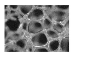
- FIG. 1 is an enlarged photograph showing the structure of a skeleton of an example of a metal porous body having a skeleton of a three-dimensional network structure.
- FIG. 2 is an enlarged view schematically showing a partial cross section of an example of a metal porous body according to an embodiment of the present invention.
- FIG. 3 is a schematic view showing an example of a state in which areas A to E are defined on the metal porous body in plan view in the method of measuring the average film thickness of the cobalt layer in the metal porous body.
- FIG. 4 is a view schematically showing an image when a cross section (a cross section taken along the line AA in FIG. 2) of the skeleton in the area A of the metal porous body shown in FIG. 3 is observed with a scanning electron microscope.
- FIG. 5 is a schematic view showing an example of the field of view (i) when the cobalt layer 11 shown in FIG. 4 is observed with a scanning electron microscope in an enlarged manner.
- FIG. 6 is a schematic view showing an example of the visual field (ii) in the case where the cobalt layer 11 shown in FIG. 4 is enlarged and observed with a scanning electron microscope.
- FIG. 7 is a schematic view showing an example of a visual field (iii) in the case where the cobalt layer 11 shown in FIG. 4 is enlarged and observed with a scanning electron microscope.
- FIG. 8 is a view schematically showing a partial cross section of an example of a porous substrate having a three-dimensional network structure.
- FIG. 9 is a photograph of a foamed urethane resin of an example of a resin molding having a skeleton of a three-dimensional network structure.
- FIG. 10 shows the porous metal body No. 1 produced in the example. It is the photograph which observed the cross section (line AA cross section of FIG. 2) of 1 frame
- FIG. 11 shows porous metal body No. 1 produced in the example. It is a figure which shows the result of having measured the cross section (line AA cross section of FIG. 2) of 1 frame
- SOFC solid oxide fuel cell
- PEFC polymer electrolyte fuel cell
- PAFC phosphoric acid fuel cell
- the SOFC includes a solid electrolyte layer formed of a solid oxide, and an electrode layer laminated on both sides of the solid electrolyte layer.
- a porous current collector is provided to collect and extract electrons generated at the electrode.
- the current collector often has a function as a gas diffusion layer in order to diffuse the gas supplied to the electrode and generate power efficiently.
- a carbon structure or a stainless steel (SUS) structure is used for a gas diffusion layer of a fuel cell.
- Grooves to be gas flow paths are formed in the carbon structure and the SUS structure.
- the width of the groove is about 500 ⁇ m, and is in the form of a straight line.
- the grooves are provided in about 1/2 of the area of the surface of the carbon structure or the SUS structure in contact with the electrolyte, so the porosity of the gas diffusion layer is about 50%. Since the gas diffusion layer as described above has a low porosity and a large pressure loss, it has been difficult to miniaturize the fuel cell while increasing the output.
- the present inventors examined using a metal porous body having a skeleton of a three-dimensional network structure instead of a carbon structure or a SUS structure as a current collector-gas diffusion layer of a fuel cell.
- a metal porous body having a skeleton of a three-dimensional network structure instead of a carbon structure or a SUS structure as a current collector-gas diffusion layer of a fuel cell.
- oxidation resistance is also required.
- a metal porous body excellent in high heat resistance for example, a metal porous body whose skeleton is made of a nickel chromium (NiCr) alloy, a nickel tin (NiSn) alloy, or a nickel tin chromium (NiSnCr) alloy can be mentioned. These metal porous bodies further have corrosion resistance and oxidation resistance, and are suitable as a collector and gas diffusion layer for the air electrode of SOFC. However, if the content of chromium (Cr) is increased to enhance the effect of high heat resistance, chromium may sublime and scatter at a high temperature of about 800 ° C., which may lower the catalyst performance of the fuel cell. is there.
- the present invention has high heat resistance, high conductivity at high temperature, and porous metal that can be suitably used as a current collector and gas diffusion layer for air electrode of SOFC. Intended to provide the body.
- a metal porous body having high heat resistance and high conductivity at high temperature which can be suitably used as a current collector and gas diffusion layer for air electrode of SOFC. be able to.
- a porous metal body according to one aspect of the present invention is A flat metal porous body having continuous pores, The skeleton of the porous metal body has an alloy layer containing nickel and at least one of chromium and tin, and a cobalt layer is formed on the surface of the alloy layer. It is a metal porous body. According to the aspect of the invention described in the above (1), it has high heat resistance and high conductivity at high temperature, and is preferably used also as a current collector and gas diffusion layer for air electrode of SOFC. A possible porous metal body can be provided.
- the porous metal body described in (1) above is The average film thickness of the cobalt layer is preferably 1 ⁇ m or more. According to the aspect of the invention described in the above (2), it is possible to provide a porous metal body having higher corrosion resistance.
- the porous metal body according to (1) or (2) above is
- the alloy layer is preferably a NiSn alloy containing Ni as a main component, a NiCr alloy containing Ni as a main component, or a NiSnCr alloy containing Ni as a main component.
- the main component of the said alloy layer shall mean the thing of the component with most ratio occupied in the said alloy layer.
- the porous metal body according to any one of (1) to (3) above It is preferable that the shape of the skeleton is a three-dimensional network structure.
- the porous metal body according to any one of (1) to (4) above, The porosity is preferably 60% or more and 98% or less.
- the porous metal body according to any one of (1) to (5) above, The average pore diameter is preferably 50 ⁇ m or more and 5000 ⁇ m or less. According to the aspect of the invention described in (4) to (6) above, it is possible to provide a metal porous body which is lightweight and has a large surface area, and which has high gas diffusion performance when used as a gas diffusion layer of a fuel cell. Can.
- the metal porous body according to any one of (1) to (6) above The thickness is preferably 500 ⁇ m or more and 5000 ⁇ m or less. According to the aspect of the invention described in (7) above, it is possible to provide a metal porous body that is lightweight and has high strength. In addition, the thickness of said metal porous body shall mean the space
- the solid oxide fuel cell according to one aspect of the present invention is It is a solid oxide fuel cell provided with the metal porous body as described in any one of said (1) to said (7) as a gas diffusion layer. According to the aspect of the invention described in the above (8), it is possible to provide a compact and lightweight solid oxide fuel cell having high power generation efficiency.
- a method for producing a porous metal body according to one aspect of the present invention It is a method of manufacturing the metal porous body according to the above (1), Providing a flat porous substrate having continuous pores; Plating cobalt on the surface of the skeleton of the porous substrate; Have The skeleton of the porous substrate has an alloy layer containing nickel and at least one of chromium and tin, It is a manufacturing method of a metal porous body. According to the aspect of the invention as described in said (9), the method of manufacturing the metal porous body as described in said (1) can be provided.
- the metal porous body according to the embodiment of the present invention has continuous pores, and has a flat plate shape as a whole.
- the continuous pores may be formed so as to penetrate the opposing main surfaces. From the viewpoint of increasing the surface area of the metal porous body, it is preferable that as many continuous pores as possible be formed.
- Examples of the shape of the skeleton of the porous metal body include mesh-like ones such as punching metal and expanded metal, and three-dimensional network-like structures.
- the skeleton of the porous metal body has an alloy layer containing nickel and at least one of chromium and tin, and a cobalt layer is formed on the surface of the alloy layer.
- the cobalt layer preferably covers the entire surface of the alloy layer containing nickel and at least one of chromium and tin.
- covering the entire surface refers to a state in which the alloy layer containing nickel and at least one of chromium and tin is not exposed at all to the surface, and nickel by pin holes, chips, etc. to the extent that the performance of SOFC is not impaired. It also includes the state in which the alloy layer containing at least one of chromium and tin is partially exposed.
- the metal porous body according to the embodiment of the present invention can suppress sublimation of chromium and tin because a cobalt layer is formed on the surface of the skeleton. Chromium and tin hardly diffuse into the cobalt layer even in a high temperature environment of about 800 ° C.
- the metal porous body according to the embodiment of the present invention does not lower the catalyst performance or reduce the strength of the skeleton even when used as the gas diffusion layer of the air electrode of SOFC, and the power generation efficiency Can provide a high SOFC. Furthermore, the surface of the cobalt layer formed on the surface of the skeleton of the metal porous body becomes cobalt oxide under the influence of oxygen. Since cobalt oxide exhibits conductivity in a high temperature environment of about 800 ° C., the metal porous body according to the embodiment of the present invention functions well not only as a gas diffusion layer but also as a current collector in a fuel cell. Do.
- the cobalt layer preferably has an average film thickness of 1 ⁇ m or more.
- the average film thickness of the cobalt layer is 1 ⁇ m or more, sublimation of chromium or tin can be sufficiently suppressed when the porous metal body is used as a gas diffusion layer of SOFC.
- the effect of suppressing the sublimation of chromium and tin is that the thickness of the cobalt layer is saturated at about 50 ⁇ m, so from the viewpoint of increasing the production cost and porosity of the metal porous body, the average film thickness of the cobalt layer is 50 ⁇ m or less It is preferable that the degree is. From these viewpoints, the average film thickness of the cobalt layer is more preferably 1 ⁇ m or more and 20 ⁇ m or less, and still more preferably 3 ⁇ m or more and 10 ⁇ m or less.
- the alloy layer may be an alloy formed of at least one of chromium and tin and nickel.
- the alloy is preferably a NiSn alloy which is an alloy of nickel and tin, a NiCr alloy which is an alloy of nickel and chromium, or a NiSnCr alloy which is an alloy of nickel, tin and chromium.
- the metal porous body has high corrosion resistance and high strength.
- other components may be intentionally or unavoidably contained in the skeleton of the porous metal body.
- aluminum, titanium, molybdenum, tungsten or the like may be contained for the purpose of improving corrosion resistance or strength.
- the content rate of chromium in a metal porous body is about 3 to 50 mass%.
- the content of chromium in the metal porous body is 3% by mass or more, the corrosion resistance of the skeleton of the metal porous body can be enhanced and the strength can be increased.
- the content of chromium in the metal porous body is 50% by mass or less, the time for the chromization treatment can be shortened and the productivity can be improved. From these viewpoints, the content of chromium in the porous metal body is more preferably 5% by mass to 47% by mass, and still more preferably 10% by mass to 45% by mass.
- the content rate of tin in a metal porous body is about 3 to 50 mass%.
- the content of tin in the metal porous body is 3% by mass or more, the corrosion resistance of the skeleton of the metal porous body can be enhanced, and high strength can be achieved.
- the content rate of tin in a metal porous body is 50 mass% or less, the time of tin plating can be shortened and productivity improves. From these viewpoints, the content of tin in the metal porous body is more preferably 5% by mass to 47% by mass, and still more preferably 10% by mass to 45% by mass.
- the shape of the skeleton of the metal porous body may be mesh-like, but it is more preferable to be a three-dimensional network-like structure.
- the shape of the skeleton is a three-dimensional network structure, the surface area can be made larger than that of a shape such as punching metal or expanded metal.
- the shape of the skeleton is more complicated, when used as a gas diffusion layer of a fuel cell, more gas can be diffused.
- FIG. 1 shows an enlarged photograph of a skeleton of a three-dimensional network structure of an example of a metal porous body according to an embodiment of the present invention.
- FIG. 2 shows an enlarged schematic view in which the cross section of the metal porous body shown in FIG. 1 is enlarged.
- the shape of the skeleton has a three-dimensional network structure, typically, as shown in FIG. 2, the interior 14 of the skeleton 13 of the porous metal body 10 is hollow.
- the skeleton 13 has a structure in which a cobalt layer 11 is formed on the surface of the alloy layer 12 which is a base material.
- the metal porous body 10 has continuous pores, and the skeleton 13 forms the pore portion 15.
- the average thickness of the cobalt layer 11 is preferably 1 ⁇ m or more and 50 ⁇ m or less as described above. The thickness is thinner than the alloy layer 12.
- the average film thickness of the cobalt layer 11 refers to what is measured by observing the cross section of the skeleton 13 of the porous metal body 10 with an electron microscope as follows. An outline of a method of measuring the average film thickness of the cobalt layer 11 is shown in FIG. 3 to FIG.
- the flat metal porous body 10 in plan view is arbitrarily divided into areas, and five places (area A to area E) are selected as measurement points. Then, at each area, the skeleton 13 of the metal porous body 10 is arbitrarily selected at one place, and an AA line cross section shown in FIG. 2 of the skeleton is observed by a scanning electron microscope (SEM).
- SEM scanning electron microscope
- the AA line cross section of the skeleton 13 of the metal porous body 10 has a substantially triangular shape as shown in FIG.
- the interior 14 of the skeleton of the porous metal body 10 is hollow, and there is a film of the alloy layer 12 facing the hollow portion.
- the cobalt layer 11 is formed to cover the outer surface of the alloy layer 12.
- the magnification is further increased to confirm the entire thickness direction of the cobalt layer 11 and to make the thickness direction appear as large as possible in one view.
- the maximum thickness and the minimum thickness of the cobalt layer 11 are measured in three different fields of view with respect to the AA line cross section of the same skeleton while changing the field of view. In all the areas, the maximum thickness and the minimum thickness of the cobalt layer are measured in three fields of view with respect to the AA line cross section of one arbitrary skeleton, and the average of them is referred to as the average film thickness of the cobalt layer.
- FIG. 5 shows a conceptual view of a visual field (i) when an AA line cross section of an arbitrary one skeleton in the area A of the metal porous body 10 shown in FIG. 3 is observed by SEM.
- FIG. 6 shows a conceptual view of another view (ii) of the AA cross section of the same skeleton
- FIG. 7 shows a conceptual view of still another view (iii).
- the thickness at which the thickness of the cobalt layer 11 is maximized in each of the visual field (i) to the visual field (iii) when the cobalt layer 11 in the AA line cross section of one arbitrary frame in the area A is observed by SEM Maximum thickness A (i), maximum thickness A (ii), maximum thickness A (iii), and thickness at which the thickness of cobalt layer 11 becomes minimum (minimum thickness a (i), minimum thickness a (ii), minimum thickness Measure a (iii)).
- the thickness of the cobalt layer 11 refers to the length of the cobalt layer 11 extending in the vertical direction from the surface of the alloy layer 12.
- the thickness of the cobalt layer 11 means a cobalt alloy layer and a cobalt layer extending in the vertical direction from the surface of the alloy layer 12.
- the sum of the 11 lengths is decided.
- the maximum thickness and the minimum thickness of the cobalt layer 11 in three fields of view are measured in the same manner as in the area A, for the AA line cross section of one arbitrary skeleton.
- the average thickness of the cobalt layer 11 is the average of the maximum thickness A (i) to the maximum thickness E (iii) and the minimum thickness a (i) to the minimum thickness e (iii) of the cobalt layer 11 measured as described above It is called thick.
- the porous metal body according to the embodiment of the present invention preferably has a porosity of 60% or more and 98% or less.
- the porosity of the porous metal body is 60% or more, the porous metal body can be made very lightweight, and furthermore, when the porous metal body is used as a gas diffusion layer of a fuel cell, gas diffusion can be achieved. Can be enhanced.
- the porosity of the metal porous body is 98% or less, the metal porous body can have sufficient strength. From these viewpoints, the porosity of the metal porous body is more preferably 70% or more and 98% or less, and still more preferably 80% or more and 98% or less.
- the porosity of the porous metal body is defined by the following equation.
- Porosity (%) (1-(Mp / (Vp x dp))) x 100
- Mp mass of porous metal body [g]
- Vp Volume of shape of appearance in porous metal body [cm 3 ]
- dp density of metal constituting the porous metal body [g / cm 3 ]
- the average pore diameter of the porous metal body is preferably 50 ⁇ m or more and 5000 ⁇ m or less.
- the strength of the metal porous body can be enhanced, and further, when the metal porous body is used as a gas diffusion layer of a fuel cell, the gas diffusivity can be enhanced.
- the bendability of a metal porous body can be improved because an average pore diameter is 5000 micrometers or less. From these viewpoints, the average pore diameter of the metal porous body is more preferably 100 ⁇ m or more and 500 ⁇ m or less, and still more preferably 150 ⁇ m or more and 400 ⁇ m or less.
- the average pore diameter of the porous metal body With the average pore diameter of the porous metal body, the surface of the porous metal body is observed with a microscope etc., the number of pores per 1 inch (25.4 mm) is counted, and the average pore diameter is calculated as 25.4 mm / number of pores. It shall mean one.
- the thickness of the porous metal body is preferably 500 ⁇ m or more and 5000 ⁇ m or less.
- the metal porous body can have sufficient strength and can have high gas diffusion performance when used as a gas diffusion layer of a fuel cell.
- the thickness of the metal porous body is 5000 ⁇ m or less, a lightweight metal porous body can be obtained. From these viewpoints, the thickness of the porous metal body is more preferably 600 ⁇ m or more and 2000 ⁇ m or less, and still more preferably 700 ⁇ m or more and 1500 ⁇ m or less.
- the solid oxide fuel cell according to the embodiment of the present invention may be provided with the metal porous body according to the above-described embodiment of the present invention as a gas diffusion layer, and the other configuration is the conventional solid oxide fuel cell Similar configurations can be employed.
- the metal porous body which concerns on embodiment of this invention can be made to act not only as a gas diffusion layer but as a collector.
- a solid oxide fuel cell operates at a high temperature of about 800 ° C.
- chromium is sublimated and scattered, resulting in deterioration of catalyst performance.
- the tin when tin is contained, the tin also sublimes and scatters, so there is a possibility that the gas diffusion layer and the current collector may become embrittled.
- the metal porous body according to the embodiment of the present invention although chromium and tin are contained in the metal porous body used as the gas diffusion layer, a cobalt layer is formed on the surface of the skeleton of the metal porous body. There is no scattering of chromium and tin. For this reason, the metal porous body according to the embodiment of the present invention does not have a concern that the catalyst performance is lowered or the gas diffusion layer is embrittled. Furthermore, since the porous metal body has high porosity, the gas can be efficiently diffused, and a solid oxide fuel cell with high power generation efficiency can be provided.
- the method for producing a metal porous body according to an embodiment of the present invention is a method for producing a metal porous body according to the above embodiment of the present invention, and a step of preparing a flat porous substrate having continuous pores. And the step of plating cobalt on the surface of the skeleton of the porous substrate. Each step is described in detail below.
- the preparation step is a step of preparing a porous substrate having continuous pores and having a flat plate shape as a whole.
- the porous substrate is formed by the substrate in the metal porous body according to the embodiment of the present invention, that is, the alloy layer 12.
- the porous base material prepared in this step may have a skeleton of a mesh shape such as punching metal or expanded metal, but more preferably has a three-dimensional network structure.
- the porous substrate may be any substrate as long as the skeleton contains nickel and at least one of chromium and tin. The contents of chromium and tin are the same as the contents of the alloy described in the metal porous body according to the embodiment of the present invention.
- FIG. 8 is an enlarged schematic view showing an enlarged cross section of an example of a porous base having a skeleton of a three-dimensional network structure.
- the skeleton 83 of the porous substrate 80 is formed of an alloy layer 82.
- the porous substrate 80 typically has a hollow interior 84 of the skeleton 83.
- the porous base material 80 has continuous pores, and the pore portion 85 is formed by the skeleton 83.
- a porous substrate having a skeleton of a three-dimensional network structure for example, Celmet (a metallic porous body containing Ni as a main component; "Celmet" is a registered trademark) manufactured by Sumitomo Electric Industries, Ltd. can be preferably used. .
- the metal porous body according to the embodiment of the present invention is formed by forming a cobalt layer on the surface of the skeleton of the porous body base 80, the porosity and the average pore diameter of the metal porous body are the same as those of the porous body base 80. And the average pore diameter are approximately equal. For this reason, the porosity and the average pore diameter of the porous substrate 80 may be appropriately selected in accordance with the porosity and the average pore diameter of the metal porous body to be manufactured. The porosity and the average pore size of the porous substrate 80 are defined in the same manner as the porosity and the average pore size of the metal porous body.
- the desired porous substrate can not be obtained from the market, it may be produced by the following method.
- a sheet-like resin molded body (hereinafter, also simply referred to as a “resin molded body”) having a skeleton of a three-dimensional network structure is prepared.
- a urethane resin, a melamine resin, etc. can be used as a resin molding.
- skeleton of a three-dimensional network structure in FIG. 9 is shown.
- a conductive treatment step of forming a conductive layer on the surface of the skeleton of the resin molded body is performed.
- the conductive treatment may be, for example, applying a conductive paint containing conductive particles such as carbon or conductive ceramic, forming a layer of a conductive metal such as nickel or copper by electroless plating, or vapor deposition Or by forming a layer of a conductive metal such as aluminum by a sputtering method. Then, the process of electroplating nickel is performed using the resin molded object which formed the conductive layer in the surface of frame
- NiSn alloy In order to manufacture a porous base material made of NiSn alloy, NiCr alloy or NiSnCr alloy by adding chromium or tin to a porous base material made of nickel, for example, chromium is added to the conductive paint in the conductive treatment step. Powder or tin powder may be mixed and used. Alternatively, a NiCr alloy, a NiSn alloy, or a NiSnCr alloy may be formed by subjecting a porous base material made of nickel to a chromizing treatment, or by plating tin on the surface of nickel followed by heat treatment.
- the chromizing treatment may be any treatment capable of diffusing and permeating chromium into a nickel porous substrate, and any known method can be adopted.
- a powder pack method in which a porous base made of nickel is filled with a penetrating material in which chromium powder, halide and alumina powder are mixed, and heating is performed in a reducing atmosphere.
- penetrant material and porous base material made of nickel are disposed apart from each other, and heated in a reducing atmosphere to form gas of the penetrant material to make the penetrant material penetrate nickel on the surface of the porous base material.
- the plating of tin can be performed, for example, as follows.
- a plating solution having a composition of 55 g / L of stannous sulfate, 100 g / L of sulfuric acid, 100 g / L of cresol sulfonic acid, 2 g / L of gelatin and 1 g / L of ⁇ -naphthol is prepared as a sulfuric acid bath, and the cathode current density is 2A. / dm 2, the anodic current density was 1A / dm 2 or less, the temperature 20 ° C., stirred (cathode rocking) with 2m / min, it may be plated with tin.
- a metal porous body having a skeleton of a three-dimensional network structure can be obtained by performing a removing step of removing the resin molded body used as the base material by heat treatment or the like.
- the porosity and the average pore diameter of the porous metal body become approximately equal to the porosity and the average pore diameter of the resin molded body used as the base material.
- the porosity and the average pore diameter of the resin molded product may be appropriately selected in accordance with the porosity and the average pore diameter of the porous base material which is the production purpose.
- the porosity and the average pore size of the resin molded body are defined in the same manner as the porosity and the average pore size of the porous metal body described above.
- the cobalt plating step is a step of plating cobalt on the surface of the skeleton of the porous substrate.
- the method of plating cobalt is not particularly limited, but, for example, it is preferable to carry out by the following method. That is, an aqueous solution having a composition of 350 g / L of cobalt sulfate, 45 g / L of cobalt chloride, 25 g / L of sodium chloride and 35 g / L of boric acid is prepared as a cobalt plating solution, and the current density is 2 A at room temperature (about 20 ° C.). By setting it as / dm ⁇ 2 >, cobalt can be plated on the surface of the skeleton of the porous substrate.
- the metal porous body according to the embodiment of the present invention can be suitably used, for example, in a gas diffusion layer for a fuel cell or an electrode for producing hydrogen by water electrolysis.
- Hydrogen production methods are roughly classified into [1] alkaline water electrolysis method, [2] PEM (Polymer Electrolyte Membrance) method, and [3] SOEC (Solid Oxide Electrolysis Cell) method.
- a porous body can be used.
- the anode and the cathode are immersed in a strong alkaline aqueous solution, and a voltage is applied to electrolyze water.
- a metal porous body as an electrode, the contact area of water and an electrode becomes large, and the efficiency of electrolysis of water can be raised.
- the porous metal body preferably has an average pore diameter of 100 ⁇ m or more and 5000 ⁇ m or less in plan view.
- the average pore diameter in a planar view of the metal porous body is 100 ⁇ m or more, generated hydrogen and oxygen bubbles are clogged in the pores of the metal porous body and the contact area between water and the electrode becomes small. Can be suppressed.
- the average pore diameter in a planar view of the metal porous body is 5000 ⁇ m or less, the surface area of the electrode becomes sufficiently large, and the efficiency of water electrolysis can be enhanced. From the same viewpoint, it is more preferable that the average pore diameter in a planar view of the metal porous body be 400 ⁇ m or more and 4000 ⁇ m or less.
- the thickness of the metal porous body and the weight per area of the metal may cause deflection or the like if the electrode area increases, and may be appropriately selected depending on the scale of the equipment.
- the weight of the metal is preferably 200 g / m 2 or more and 2000 g / m 2 or less, more preferably 300 g / m 2 or more and 1200 g / m 2 or less, and more preferably 400 g / m 2 or more and 1000 g It is further preferable that the ratio is about / m 2 or less.
- a plurality of metal porous bodies having different average pore sizes can be used in combination.
- the PEM method of the above [2] is a method of electrolyzing water using a solid polymer electrolyte membrane.
- An anode and a cathode are disposed on both sides of the solid polymer electrolyte membrane, and a voltage is applied while flowing water on the anode side, whereby hydrogen ions generated by the electrolysis of water are moved to the cathode side through the solid polymer electrolyte membrane
- the hydrogen is taken out as hydrogen on the cathode side.
- the operating temperature is about 100 ° C.
- a polymer electrolyte fuel cell that generates electric power by hydrogen and oxygen and discharges water is the same as that of the solid polymer fuel cell, and the operation is completely reversed.
- the electrode Since the anode side and the cathode side are completely separated, there is an advantage that high purity hydrogen can be taken out. Since it is necessary for both the anode and the cathode to permeate the electrode and pass water and hydrogen gas, the electrode needs a conductive porous body.
- the metal porous body according to the embodiment of the present invention has high porosity and good electrical conductivity, it can be used for PEM type water electrolysis as well as it can be suitably used for a polymer electrolyte fuel cell. It can be used suitably.
- the porous metal body preferably has an average pore diameter of 150 ⁇ m or more and 1000 ⁇ m or less when viewed in plan. When the average pore diameter in a planar view of the metal porous body is 150 ⁇ m or more, generated hydrogen and oxygen bubbles are clogged in the pores of the metal porous body and the contact area between water and the solid polymer electrolyte membrane Can be suppressed.
- the average pore diameter in a planar view of the metal porous body is 1000 ⁇ m or less, sufficient water retentivity can be secured, and water can be prevented from passing through before reaction to improve efficiency. It can perform electrolysis of water well.
- the average pore diameter when the metal porous body is viewed in plan is more preferably 200 ⁇ m or more and 700 ⁇ m or less, and still more preferably 300 ⁇ m or more and 600 ⁇ m or less.
- the thickness of metal porous body and the weight per area of metal may be selected appropriately depending on the scale of equipment, but if the porosity is too small, the pressure loss for passing water will be large, so the porosity should be 30% or more It is preferable to adjust the thickness and the weight of the metal so that In addition, in the PEM method, the conduction between the solid polymer electrolyte membrane and the electrode is crimped, so adjust the amount of metal attached to the metal so that the increase in electrical resistance due to deformation and creep at the time of pressurization becomes a problem in practical use. There is a need.
- the weight of the metal is preferably 200 g / m 2 or more and 2000 g / m 2 or less, more preferably 300 g / m 2 or more and 1200 g / m 2 or less, and more preferably 400 g / m 2 or more and 1000 g It is further preferable that the ratio is about / m 2 or less.
- the SOEC system of the above [3] is a method of electrolyzing water using a solid oxide electrolyte membrane, and the constitution differs depending on whether the electrolyte membrane is a proton conductive membrane or an oxygen ion conductive membrane.
- the oxygen ion conductive film hydrogen is generated on the cathode side supplying water vapor, so the hydrogen purity is lowered. Therefore, from the viewpoint of hydrogen production, it is preferable to use a proton conductive membrane.
- An anode and a cathode are disposed on both sides of the proton conducting membrane, and a voltage is applied while introducing water vapor on the anode side, thereby moving hydrogen ions generated by the electrolysis of water to the cathode side through the solid oxide electrolyte membrane.
- the operating temperature is about 600 ° C. or more and 800 ° C. or less.
- a solid oxide fuel cell that generates electric power by hydrogen and oxygen and discharges the water, and operates in the completely opposite manner with the same configuration.
- Both the anode and the cathode need to be permeable to the electrode to pass water vapor and hydrogen gas, so the electrode needs to be a porous body that is electrically conductive and, in particular, resistant to a high temperature oxidizing atmosphere on the anode side.
- the porous metal body according to the embodiment of the present invention has high porosity, good electrical conductivity, high oxidation resistance and heat resistance, it is the same as suitable for use in solid oxide fuel cells. It can be suitably used for SOEC type water electrolysis. It is preferable to use a metal porous body containing chromium or tin, since high oxidation resistance is required for the electrode on the side to be the oxidizing atmosphere.
- the porous metal body preferably has an average pore diameter of 150 ⁇ m or more and 1000 ⁇ m or less when viewed in plan.
- the average pore diameter in a planar view of the metal porous body is 150 ⁇ m or more, water vapor and generated hydrogen are clogged in the pores of the metal porous body and the contact area between the water vapor and the solid oxide electrolyte membrane is small It is possible to suppress the Moreover, when the metal porous body is viewed in plan, when the average pore diameter is 1000 ⁇ m or less, it is possible to suppress that the pressure loss becomes too low and the water vapor passes through before sufficiently reacting. From the same viewpoint, the average pore diameter when the metal porous body is viewed in plan is more preferably 200 ⁇ m or more and 700 ⁇ m or less, and still more preferably 300 ⁇ m or more and 600 ⁇ m or less.
- the thickness of the metal porous body and the weight of the metal may be appropriately selected depending on the scale of the equipment, but if the porosity is too small, the pressure loss for introducing water vapor becomes large, so the porosity is 30% or more It is preferable to adjust the thickness and the weight of the metal so that In addition, in the SOEC method, the conduction between the solid oxide electrolyte membrane and the electrode is crimped, so it is necessary to adjust the metal coating weight so that the increase in electrical resistance due to deformation and creep at the time of pressure becomes a practically acceptable range. There is.
- the weight of the metal is preferably 200 g / m 2 or more and 2000 g / m 2 or less, more preferably 300 g / m 2 or more and 1200 g / m 2 or less, and more preferably 400 g / m 2 or more and 1000 g It is further preferable that the ratio is about / m 2 or less.
- the metal porous body is disposed on both sides of a solid polymer electrolyte membrane, and the solid polymer electrolyte membrane and the metal porous body are brought into contact with each other, and each metal porous body acts as an anode and a cathode. 15. The method for producing hydrogen according to any one of appendices 1 to 8, wherein hydrogen is generated on the cathode side by supplying and electrolyzing the hydrogen. (Supplementary Note 10) The metal porous body is disposed on both sides of a solid oxide electrolyte membrane, and the solid polymer electrolyte membrane and the metal porous body are brought into contact with each other, and each metal porous body acts as an anode and a cathode. 15. The method for producing hydrogen according to any one of appendices 1 to 8, wherein hydrogen is generated on the cathode side by supplying water to electrolyze water.
- An apparatus for producing hydrogen capable of generating hydrogen by electrolyzing water Comprising a flat metal porous body provided with continuous pores as an electrode;
- the porous metal body includes an alloy layer containing nickel and at least one of chromium and tin, and a cobalt layer is formed on the entire surface of the alloy layer.
- Hydrogen production equipment (Supplementary Note 12) The apparatus for producing hydrogen according to appendix 11, wherein the cobalt layer has an average film thickness of 1 ⁇ m or more.
- Example 1 Preparation process- A porous base material No. 2 having a skeleton of a three-dimensional network structure, a chromium content of 27% by mass and Ni as a main component. 1 (Celmet manufactured by Sumitomo Electric Industries, Ltd., "Celmet” is a registered trademark) was prepared. Porous substrate No. 1 1 had a thickness of 1200 ⁇ m, a porosity of 96%, and an average pore diameter of 440 ⁇ m. -Cobalt plating process- The porous substrate No. 1 prepared above was prepared. Cobalt was plated on the surface of the skeleton of No. 1 so that the weight per unit area was 100 g / m 2 . I got one.
- cobalt plating For cobalt plating, prepare a cobalt plating solution with a composition of 350 g / L of cobalt sulfate, 45 g / L of cobalt chloride, 25 g / L of sodium chloride and 35 g / L of boric acid, and use 2A current density at room temperature (about 20 ° C). / was carried out by a dm 2. The current density is based on the apparent area of the porous substrate.
- Example 2 Preparation process- A porous substrate No. 1 having a skeleton of a three-dimensional network structure and containing 7% by mass of tin and Ni as a main component. I prepared two. Porous substrate No. 1 2 has a thickness of 1200 ⁇ m, a porosity of 96%, an average pore diameter of 440 ⁇ m, and a surface weight of 32 g / m 2 on the surface of the skeleton of Celmet (Sumitomo Electric Industries, Ltd., “Celmet” is a registered trademark) Tin was plated as described above, and heat treatment was performed at 1000 ° C. for 15 minutes.
- Celmet Suditomo Electric Industries, Ltd., “Celmet” is a registered trademark
- Tin plating is performed using a tin plating solution having a composition of 55 g / L stannous sulfate, 100 g / L sulfuric acid, 100 g / L cresol sulfonic acid, 2 g / L gelatin, and 1 g / L ⁇ -naphthol, and the temperature of the plating solution is 20 °C and it was performed at a current density of 2A / dm 2.
- -Cobalt plating process The porous substrate No. 1 prepared above was prepared. The surface of the skeleton of No. 2 was plated with cobalt so that the weight per unit area was 100 g / cm 2 . I got two. The plating of cobalt was performed in the same manner as in Example 1.
- FIG. 11 shows an SEM photograph at the top and a spectrum at the bottom showing the presence or absence of each element.
- the vertical axis represents the weight ratio of each element
- the horizontal axis represents the position on the line L in the SEM photograph. It was confirmed from FIG. 11 that chromium in the alloy layer 12 hardly diffused to the cobalt layer 11.
- porous metal body No. No. 1 and porous metal No. 1 No. 2 is a conventional porous substrate No. It was confirmed that the same level of strength as 1 could be maintained.
- porous metal body No. No. 1 and porous metal No. 1 No. 2 is a conventional porous substrate No. It showed extremely low resistance at a high temperature of 800 ° C., compared to 1 and showed that it can be suitably used as a current collector of SOFC.
Abstract
A metal porous body according to an embodiment of the present invention has a flat shape and continuous pores. The metal porous body skeleton has an alloy layer containing nickel, chromium and/or tin, and a cobalt layer is formed on the surface of the alloy layer.
Description
本発明は、金属多孔体、固体酸化物型燃料電池及び金属多孔体の製造方法に関する。
本出願は、2017年7月14日出願の日本出願第2017-138140号に基づく優先権を主張し、前記日本出願に記載された全ての記載内容を援用するものである。 The present invention relates to a porous metal body, a solid oxide fuel cell, and a method of producing the porous metal body.
This application claims priority based on Japanese Patent Application No. 2017-138140 filed on Jul. 14, 2017, and incorporates all the contents described in the aforementioned Japanese application.
従来、気孔率が高く表面積の大きな金属多孔体の製造方法として、発泡樹脂等の樹脂成形体の表面に金属層を形成する方法が知られている。例えば特開平11-154517号公報(特許文献1)には、樹脂成形体の骨格の表面を導電化処理し、この上に金属からなる電気めっき層を形成し、必要に応じて樹脂成形体を焼却して除去することにより金属多孔体を製造する方法が記載されている。
Conventionally, as a method for producing a metal porous body having a high porosity and a large surface area, a method of forming a metal layer on the surface of a resin molded product such as a foamed resin is known. For example, in Japanese Patent Application Laid-Open No. 11-154517 (Patent Document 1), the surface of the skeleton of a resin molded body is treated to be conductive, an electroplating layer made of metal is formed thereon, and the resin molded body is A method of producing a porous metal body by incineration and removal is described.
また、特開2012-132083号公報(特許文献2)では、耐酸化性及び耐食性を有するとともに気孔率が大きく、各種電池、キャパシタ、燃料電池等の集電体に適した金属多孔体として、ニッケルスズ合金からなる金属多孔体が提案されている。更に、特開2012-149282号公報(特許文献3)では、高い耐食性を有する金属多孔体として、ニッケルクロム合金からなる金属多孔体が提案されている。
Further, in JP 2012-132083 A (Patent Document 2), nickel is used as a metal porous body having oxidation resistance and corrosion resistance and a large porosity, which is suitable for current collectors of various batteries, capacitors, fuel cells and the like. A metal porous body made of a tin alloy has been proposed. Furthermore, in JP 2012-149282 (Patent Document 3), a metal porous body made of a nickel chromium alloy is proposed as a metal porous body having high corrosion resistance.
本発明の一態様に係る金属多孔体は、
連続気孔を有する平板状の金属多孔体であって、
前記金属多孔体の骨格は、ニッケルと、クロム及びスズの少なくとも一方と、を含有する合金層を有し、前記合金層の表面にコバルト層が形成されている、
金属多孔体である。 The metal porous body according to one aspect of the present invention is
A flat metal porous body having continuous pores,
The skeleton of the porous metal body has an alloy layer containing nickel and at least one of chromium and tin, and a cobalt layer is formed on the surface of the alloy layer.
It is a metal porous body.
本発明の一態様に係る金属多孔体の製造方法は、
上記の本発明の一態様に係る金属多孔体を製造する方法であって、
連続気孔を有する平板状の多孔体基材を用意する工程と、
前記多孔体基材の骨格の表面にコバルトをめっきする工程と、
を有し、
前記多孔体基材の骨格は、ニッケルと、クロム及びスズの少なくとも一方と、を含有する合金層を有する、
金属多孔体の製造方法。 The method for producing a porous metal body according to one aspect of the present invention is
A method for producing a porous metal body according to one aspect of the present invention described above,
Providing a flat porous substrate having continuous pores;
Plating cobalt on the surface of the skeleton of the porous substrate;
Have
The skeleton of the porous substrate has an alloy layer containing nickel and at least one of chromium and tin,
Method of manufacturing porous metal body.
[本開示が解決しようとする課題]
[Problems to be solved by the present disclosure]
各種燃料電池のなかでも、固体酸化物型燃料電池(Solid Oxide Fuel Cell;SOFC、以下「SOFC」とも記す)は、固体高分子型燃料電池(Polymer Electrolyte Fuel Cell:PEFC)やリン酸型燃料電池(Phosphoric Acid Fuel Cell:PAFC)に比べて高温で作動させる必要があるが、発電効率が高い、白金等の高価な触媒を必要としない、排熱を利用できるなどの利点を有するため、開発が盛んに進められている。
前記SOFCは、固体酸化物から形成された固体電解質層と、この固体電解質層を挟んで両側に積層形成された電極層とを備えて構成されている。また、電極で生成される電子を収集して取り出すために多孔質の集電体が設けられている。この集電体は電極に供給されるガスを拡散して効率よく発電させるためにガス拡散層としての機能を備えている場合が多い。 Among various fuel cells, a solid oxide fuel cell (SOFC, hereinafter also referred to as "SOFC") is a polymer electrolyte fuel cell (PEFC) or a phosphoric acid fuel cell. (Phosphoric Acid Fuel Cell: PAFC) needs to be operated at high temperature, but has high power generation efficiency, does not require expensive catalysts such as platinum, and can be used for exhaust heat. It is actively promoted.
The SOFC includes a solid electrolyte layer formed of a solid oxide, and an electrode layer laminated on both sides of the solid electrolyte layer. In addition, a porous current collector is provided to collect and extract electrons generated at the electrode. The current collector often has a function as a gas diffusion layer in order to diffuse the gas supplied to the electrode and generate power efficiently.
燃料電池のガス拡散層には、一般に、カーボン構造体やステンレス鋼(SUS)構造体が利用されている。カーボン構造体やSUS構造体にはガス流路となる溝が形成されている。溝の幅は約500μm程度であり、一繋がりの線状になっている。溝は、カーボン構造体やSUS構造体が電解質と接触する面の面積の約1/2程度に設けられているため、ガス拡散層の気孔率は50%程度である。
上記のようなガス拡散層は気孔率がそれほど高くなく、また、圧力損失も大きいため、燃料電池を小型化しつつ出力を大きくすることが困難であった。 Generally, a carbon structure or a stainless steel (SUS) structure is used for a gas diffusion layer of a fuel cell. Grooves to be gas flow paths are formed in the carbon structure and the SUS structure. The width of the groove is about 500 μm, and is in the form of a straight line. The grooves are provided in about 1/2 of the area of the surface of the carbon structure or the SUS structure in contact with the electrolyte, so the porosity of the gas diffusion layer is about 50%.
Since the gas diffusion layer as described above has a low porosity and a large pressure loss, it has been difficult to miniaturize the fuel cell while increasing the output.
本発明者等は、燃料電池の集電体兼ガス拡散層としてカーボン構造体やSUS構造体の代わりに三次元網目状構造の骨格を有する金属多孔体を用いることを検討した。
SOFCは800℃程度の高温で作動させるため、集電体兼ガス拡散層として金属多孔体を用いるには高耐熱性を備えている必要がある。また、空気極側では高温下で酸化が進行するため、耐酸化性も要求される。 The present inventors examined using a metal porous body having a skeleton of a three-dimensional network structure instead of a carbon structure or a SUS structure as a current collector-gas diffusion layer of a fuel cell.
In order to operate SOFC at a high temperature of about 800 ° C., it is necessary to have high heat resistance in order to use a metal porous body as a current collector and gas diffusion layer. In addition, since oxidation proceeds at high temperature on the air electrode side, oxidation resistance is also required.
高耐熱性に優れた金属多孔体としては、例えば、骨格がニッケルクロム(NiCr)合金やニッケルスズ(NiSn)合金、ニッケルスズクロム(NiSnCr)合金からなる金属多孔体が挙げられる。これらの金属多孔体は更に耐食性や耐酸化性も備えており、SOFCの空気極用の集電体兼ガス拡散層として好適である。
しかしながら高耐熱性の効果を高めるためにクロム(Cr)の含有量を多くすると、クロムは800℃程度の高温下では昇華して飛散してしまい、燃料電池の触媒性能を低下させてしまう虞がある。また、クロムやスズ(Sn)が金属多孔体の骨格の表面から昇華すると、クロムやスズが抜けた部分の骨格は表面が粗くなり、骨格の強度の低下につながってしまう。更に、クロムは導電性が低いため、SOFCの空気極において集電性能を高めるという点においても改良の余地がある。 As a metal porous body excellent in high heat resistance, for example, a metal porous body whose skeleton is made of a nickel chromium (NiCr) alloy, a nickel tin (NiSn) alloy, or a nickel tin chromium (NiSnCr) alloy can be mentioned. These metal porous bodies further have corrosion resistance and oxidation resistance, and are suitable as a collector and gas diffusion layer for the air electrode of SOFC.
However, if the content of chromium (Cr) is increased to enhance the effect of high heat resistance, chromium may sublime and scatter at a high temperature of about 800 ° C., which may lower the catalyst performance of the fuel cell. is there. In addition, when chromium or tin (Sn) is sublimed from the surface of the skeleton of the metal porous body, the skeleton of the part from which chromium or tin is removed is roughened, leading to a decrease in the strength of the skeleton. Furthermore, since chromium has low conductivity, there is room for improvement in terms of enhancing the current collection performance at the SOFC air electrode.
そこで本発明は上記問題点に鑑み、高耐熱性を有し、かつ高温下で導電性が高く、SOFCの空気極用の集電体兼ガス拡散層としても好適に用いることが可能な金属多孔体を提供することを目的とする。
Therefore, in view of the above problems, the present invention has high heat resistance, high conductivity at high temperature, and porous metal that can be suitably used as a current collector and gas diffusion layer for air electrode of SOFC. Intended to provide the body.
[本開示の効果]
本開示によれば、高耐熱性を有し、かつ高温下で導電性が高く、SOFCの空気極用の集電体兼ガス拡散層としても好適に用いることが可能な金属多孔体を提供することができる。 [Effect of the present disclosure]
According to the present disclosure, there is provided a metal porous body having high heat resistance and high conductivity at high temperature, and which can be suitably used as a current collector and gas diffusion layer for air electrode of SOFC. be able to.
[本発明の実施形態の説明]
最初に本発明の実施態様を列記して説明する。
(1)本発明の一態様に係る金属多孔体は、
連続気孔を有する平板状の金属多孔体であって、
前記金属多孔体の骨格は、ニッケルと、クロム及びスズの少なくとも一方と、を含有する合金層を有し、前記合金層の表面にコバルト層が形成されている、
金属多孔体、である。
上記(1)に記載の発明の態様によれば、高耐熱性を有し、かつ高温下で導電性が高く、SOFCの空気極用の集電体兼ガス拡散層としても好適に用いることが可能な金属多孔体を提供することができる。 Description of the embodiment of the present invention
First, the embodiments of the present invention will be listed and described.
(1) A porous metal body according to one aspect of the present invention is
A flat metal porous body having continuous pores,
The skeleton of the porous metal body has an alloy layer containing nickel and at least one of chromium and tin, and a cobalt layer is formed on the surface of the alloy layer.
It is a metal porous body.
According to the aspect of the invention described in the above (1), it has high heat resistance and high conductivity at high temperature, and is preferably used also as a current collector and gas diffusion layer for air electrode of SOFC. A possible porous metal body can be provided.
(2)上記(1)に記載の金属多孔体は、
前記コバルト層の平均膜厚が1μm以上であることが好ましい。
上記(2)に記載の発明の態様によれば、より高い耐食性を有する金属多孔体を提供することができる。 (2) The porous metal body described in (1) above is
The average film thickness of the cobalt layer is preferably 1 μm or more.
According to the aspect of the invention described in the above (2), it is possible to provide a porous metal body having higher corrosion resistance.
(3)上記(1)又は上記(2)に記載の金属多孔体は、
前記合金層はNiを主成分とするNiSn合金、Niを主成分とするNiCr合金又はNiを主成分とするNiSnCr合金であることが好ましい。
上記(3)に記載の発明の態様によれば、耐食性が高く、また高強度の金属多孔体を提供することができる。
なお、前記合金層の主成分とは、前記合金層において占める割合が最も多い成分のことをいうものとする。 (3) The porous metal body according to (1) or (2) above is
The alloy layer is preferably a NiSn alloy containing Ni as a main component, a NiCr alloy containing Ni as a main component, or a NiSnCr alloy containing Ni as a main component.
According to the aspect of the invention described in the above (3), it is possible to provide a metal porous body having high corrosion resistance and high strength.
In addition, the main component of the said alloy layer shall mean the thing of the component with most ratio occupied in the said alloy layer.
(4)上記(1)から上記(3)のいずれか一項に記載の金属多孔体は、
前記骨格の形状が三次元網目状構造であることが好ましい。
(5)上記(1)から上記(4)のいずれか一項に記載の金属多孔体は、
気孔率が60%以上、98%以下であることが好ましい。
(6)上記(1)から上記(5)のいずれか一項に記載の金属多孔体は、
平均気孔径が50μm以上、5000μm以下であることが好ましい。
上記(4)から上記(6)に記載の発明の態様によれば、軽量でかつ表面積が大きく、燃料電池のガス拡散層として使用した場合にガスの拡散性能の高い金属多孔体を提供することができる。 (4) The porous metal body according to any one of (1) to (3) above,
It is preferable that the shape of the skeleton is a three-dimensional network structure.
(5) The porous metal body according to any one of (1) to (4) above,
The porosity is preferably 60% or more and 98% or less.
(6) The porous metal body according to any one of (1) to (5) above,
The average pore diameter is preferably 50 μm or more and 5000 μm or less.
According to the aspect of the invention described in (4) to (6) above, it is possible to provide a metal porous body which is lightweight and has a large surface area, and which has high gas diffusion performance when used as a gas diffusion layer of a fuel cell. Can.
(7)上記(1)から上記(6)のいずれか一項に記載の金属多孔体は、
厚みが500μm以上、5000μm以下であることが好ましい。
上記(7)に記載の発明の態様によれば、軽量でかつ強度が高い金属多孔体を提供することができる。
なお、上記の金属多孔体の厚みとは、平板状の金属多孔体の主面同士の間隔をいうものとする。 (7) The metal porous body according to any one of (1) to (6) above,
The thickness is preferably 500 μm or more and 5000 μm or less.
According to the aspect of the invention described in (7) above, it is possible to provide a metal porous body that is lightweight and has high strength.
In addition, the thickness of said metal porous body shall mean the space | interval of the main surfaces of a flat metal porous body.
(8)本発明の一態様に係る固体酸化物型燃料電池は、
上記(1)から上記(7)のいずれか一項に記載の金属多孔体をガス拡散層として備える固体酸化物型燃料電池、である。
上記(8)に記載の発明の態様によれば、発電効率が高く、小型で軽量な固体酸化物型燃料電池を提供することができる。 (8) The solid oxide fuel cell according to one aspect of the present invention is
It is a solid oxide fuel cell provided with the metal porous body as described in any one of said (1) to said (7) as a gas diffusion layer.
According to the aspect of the invention described in the above (8), it is possible to provide a compact and lightweight solid oxide fuel cell having high power generation efficiency.
(9)本発明の一態様に係る金属多孔体の製造方法は、
上記(1)に記載の金属多孔体、を製造する方法であって、
連続気孔を有する平板状の多孔体基材を用意する工程と、
前記多孔体基材の骨格の表面にコバルトをめっきする工程と、
を有し、
前記多孔体基材の骨格は、ニッケルと、クロム及びスズの少なくとも一方と、を含有する合金層を有する、
金属多孔体の製造方法である。
上記(9)に記載の発明の態様によれば、上記(1)に記載の金属多孔体を製造する方法を提供することができる。 (9) A method for producing a porous metal body according to one aspect of the present invention,
It is a method of manufacturing the metal porous body according to the above (1),
Providing a flat porous substrate having continuous pores;
Plating cobalt on the surface of the skeleton of the porous substrate;
Have
The skeleton of the porous substrate has an alloy layer containing nickel and at least one of chromium and tin,
It is a manufacturing method of a metal porous body.
According to the aspect of the invention as described in said (9), the method of manufacturing the metal porous body as described in said (1) can be provided.
(10)上記(9)に記載の金属多孔体の製造方法は、
前記多孔体基材の骨格の形状が三次元網目状構造であることが好ましい。
上記(10)に記載の発明の態様によれば、上記(4)に記載の金属多孔体を製造する方法を提供することができる。 (10) The method for producing a porous metal body according to (9) above,
It is preferable that the shape of the skeleton of the porous substrate is a three-dimensional network structure.
According to the aspect of the invention as described in said (10), the method of manufacturing the metal porous body as described in said (4) can be provided.
[本発明の実施態様の詳細]
本発明の実施態様に係る金属多孔体、固体酸化物型燃料電池及び金属多孔体の製造方法の具体例を、以下に、より詳細に説明する。なお、本発明はこれらの例示に限定されるものではなく、請求の範囲によって示され、請求の範囲と均等の意味および範囲内でのすべての変更が含まれることが意図される。 [Details of the embodiment of the present invention]
Specific examples of the porous metal body, the solid oxide fuel cell, and the method of producing the porous metal body according to the embodiment of the present invention will be described in more detail below. The present invention is not limited to these exemplifications, is shown by the claims, and is intended to include all modifications within the scope and meaning equivalent to the claims.
<金属多孔体>
本発明の実施形態に係る金属多孔体は連続気孔を有し、全体として平板状の形状をしている。金属多孔体において連続気孔は対向する主面を貫通するように形成されていればよい。金属多孔体の表面積を大きくする観点からは、なるべく多くの連続気孔が形成されていることが好ましい。金属多孔体の骨格の形状としては、例えば、パンチングメタルやエキスパンドメタルのようなメッシュ状のものや、三次元網目状構造のようなものが挙げられる。 <Porous metal body>
The metal porous body according to the embodiment of the present invention has continuous pores, and has a flat plate shape as a whole. In the metal porous body, the continuous pores may be formed so as to penetrate the opposing main surfaces. From the viewpoint of increasing the surface area of the metal porous body, it is preferable that as many continuous pores as possible be formed. Examples of the shape of the skeleton of the porous metal body include mesh-like ones such as punching metal and expanded metal, and three-dimensional network-like structures.
金属多孔体の骨格は、ニッケルと、クロム及びスズの少なくとも一方と、を含有する合金層を有し、前記合金層の表面に、コバルト層が形成されている。前記コバルト層はニッケルと、クロム及びスズの少なくとも一方と、を含有する合金層の表面全体を覆うのが好ましい。ここで表面全体を覆うとは、ニッケルと、クロム及びスズの少なくとも一方と、を含有する合金層が表面に全く露出しない状態の他、SOFCの性能を損なわない程度においてピンホール、欠け等によりニッケルと、クロム及びスズの少なくとも一方と、を含有する合金層が一部露出している状態も含む。
従来のクロムやスズを含有する金属多孔体は、SOFCのガス拡散層として用いると高温下でクロムやスズが昇華して触媒性能を低下させたり、骨格の強度が低下したりする虞があったが、本発明の実施形態に係る金属多孔体は骨格の表面にコバルト層が形成されているためクロムやスズの昇華を抑制することができる。クロムやスズは800℃程度の高温環境下でもコバルト層中に殆ど拡散しない。このため本発明の実施形態に係る金属多孔体は、SOFCの空気極のガス拡散層として用いた場合にも、触媒性能を低下させたり、骨格の強度を低下させたりすることがなく、発電効率が高いSOFCを提供することができる。更に、金属多孔体の骨格の表面に形成されているコバルト層の表面は酸素の影響によって酸化コバルトとなる。酸化コバルトは800℃程度の高温環境下で導電性を発揮するようになるため、本発明の実施形態に係る金属多孔体は燃料電池においてガス拡散層としてだけでなく集電体としても良好に機能する。 The skeleton of the porous metal body has an alloy layer containing nickel and at least one of chromium and tin, and a cobalt layer is formed on the surface of the alloy layer. The cobalt layer preferably covers the entire surface of the alloy layer containing nickel and at least one of chromium and tin. Here, covering the entire surface refers to a state in which the alloy layer containing nickel and at least one of chromium and tin is not exposed at all to the surface, and nickel by pin holes, chips, etc. to the extent that the performance of SOFC is not impaired. It also includes the state in which the alloy layer containing at least one of chromium and tin is partially exposed.
When a conventional metal porous body containing chromium or tin is used as a gas diffusion layer of SOFC, there is a risk that the chromium or tin will sublime at high temperature to lower the catalyst performance or the strength of the skeleton. However, the metal porous body according to the embodiment of the present invention can suppress sublimation of chromium and tin because a cobalt layer is formed on the surface of the skeleton. Chromium and tin hardly diffuse into the cobalt layer even in a high temperature environment of about 800 ° C. Therefore, the metal porous body according to the embodiment of the present invention does not lower the catalyst performance or reduce the strength of the skeleton even when used as the gas diffusion layer of the air electrode of SOFC, and the power generation efficiency Can provide a high SOFC. Furthermore, the surface of the cobalt layer formed on the surface of the skeleton of the metal porous body becomes cobalt oxide under the influence of oxygen. Since cobalt oxide exhibits conductivity in a high temperature environment of about 800 ° C., the metal porous body according to the embodiment of the present invention functions well not only as a gas diffusion layer but also as a current collector in a fuel cell. Do.
前記コバルト層は、平均膜厚が1μm以上であることが好ましい。コバルト層の平均膜厚が1μm以上であることにより、金属多孔体をSOFCのガス拡散層として用いた場合にクロムやスズの昇華を十分に抑制することができる。また、クロムやスズの昇華の抑制の効果は、コバルト層の厚みが50μm程度で飽和するため、金属多孔体の製造コストや気孔率を大きくする観点からは、コバルト層の平均膜厚は50μm以下程度であることが好ましい。これらの観点から、コバルト層の平均膜厚は、1μm以上、20μm以下であることがより好ましく、3μm以上、10μm以下であることが更に好ましい。
The cobalt layer preferably has an average film thickness of 1 μm or more. When the average film thickness of the cobalt layer is 1 μm or more, sublimation of chromium or tin can be sufficiently suppressed when the porous metal body is used as a gas diffusion layer of SOFC. In addition, the effect of suppressing the sublimation of chromium and tin is that the thickness of the cobalt layer is saturated at about 50 μm, so from the viewpoint of increasing the production cost and porosity of the metal porous body, the average film thickness of the cobalt layer is 50 μm or less It is preferable that the degree is. From these viewpoints, the average film thickness of the cobalt layer is more preferably 1 μm or more and 20 μm or less, and still more preferably 3 μm or more and 10 μm or less.
前記合金層は、クロム及びスズの少なくとも一方と、ニッケルとによって形成された合金であればよい。例えば、前記合金は、ニッケルとスズとの合金であるNiSn合金や、ニッケルとクロムとの合金であるNiCr合金、ニッケルとスズとクロムとの合金であるNiSnCr合金であることが好ましい。NiCr合金やNiSn合金、NiSnCr合金であることにより、耐食性が高く、高強度の金属多孔体となる。
なお、金属多孔体の骨格には前記合金成分の他にも、意図的又は不可避的に他の成分が含まれていてもよい。例えば、耐食性や強度の向上を目的としてアルミニウムやチタン、モリブデン、タングステン等が含まれていてもよい。 The alloy layer may be an alloy formed of at least one of chromium and tin and nickel. For example, the alloy is preferably a NiSn alloy which is an alloy of nickel and tin, a NiCr alloy which is an alloy of nickel and chromium, or a NiSnCr alloy which is an alloy of nickel, tin and chromium. By being a NiCr alloy, a NiSn alloy, or a NiSnCr alloy, the metal porous body has high corrosion resistance and high strength.
In addition to the above-mentioned alloy components, other components may be intentionally or unavoidably contained in the skeleton of the porous metal body. For example, aluminum, titanium, molybdenum, tungsten or the like may be contained for the purpose of improving corrosion resistance or strength.
前記合金層がクロムを含有する場合には、金属多孔体におけるクロムの含有率は3質量%以上、50質量%以下程度であることが好ましい。金属多孔体におけるクロムの含有率が3質量%以上であることにより金属多孔体の骨格の耐食性を高め、かつ高強度にすることができる。また、金属多孔体におけるクロムの含有率が50質量%以下であることにより、クロマイズ処理の時間を短くでき生産性が向上する。これらの観点から、金属多孔体におけるクロムの含有率は5質量%以上、47質量%以下であることがより好ましく、10質量%以上、45質量%以下であることが更に好ましい。
When the said alloy layer contains chromium, it is preferable that the content rate of chromium in a metal porous body is about 3 to 50 mass%. When the content of chromium in the metal porous body is 3% by mass or more, the corrosion resistance of the skeleton of the metal porous body can be enhanced and the strength can be increased. In addition, when the content of chromium in the metal porous body is 50% by mass or less, the time for the chromization treatment can be shortened and the productivity can be improved. From these viewpoints, the content of chromium in the porous metal body is more preferably 5% by mass to 47% by mass, and still more preferably 10% by mass to 45% by mass.
前記合金層がスズを含有する場合には、金属多孔体におけるスズの含有率は3質量%以上、50質量%以下程度であることが好ましい。金属多孔体におけるスズの含有率が3質量%以上であることにより金属多孔体の骨格の耐食性を高め、かつ高強度にすることができる。また、金属多孔体におけるスズの含有率が50質量%以下であることにより、スズめっきの時間を短くでき生産性が向上する。これらの観点から、金属多孔体におけるスズの含有率は5質量%以上、47質量%以下であることがより好ましく、10質量%以上、45質量%以下であることが更に好ましい。
When the said alloy layer contains tin, it is preferable that the content rate of tin in a metal porous body is about 3 to 50 mass%. When the content of tin in the metal porous body is 3% by mass or more, the corrosion resistance of the skeleton of the metal porous body can be enhanced, and high strength can be achieved. Moreover, since the content rate of tin in a metal porous body is 50 mass% or less, the time of tin plating can be shortened and productivity improves. From these viewpoints, the content of tin in the metal porous body is more preferably 5% by mass to 47% by mass, and still more preferably 10% by mass to 45% by mass.
前述のように金属多孔体の骨格の形状はメッシュ状のものであってもよいが、三次元網目状構造であることがより好ましい。骨格の形状が三次元網目状構造の場合には、パンチングメタルやエキスパンドメタルのような形状のものよりも更に表面積を大きくすることができる。また、骨格の形状がより複雑であるため、燃料電池のガス拡散層として用いた場合に、ガスをより多く拡散させることができる。
As described above, the shape of the skeleton of the metal porous body may be mesh-like, but it is more preferable to be a three-dimensional network-like structure. When the shape of the skeleton is a three-dimensional network structure, the surface area can be made larger than that of a shape such as punching metal or expanded metal. In addition, since the shape of the skeleton is more complicated, when used as a gas diffusion layer of a fuel cell, more gas can be diffused.
以下では、金属多孔体の骨格の形状が三次元網目状構造である場合を例にして本発明の実施形態に係る金属多孔体をより詳細に説明する。
図1に、本発明の実施形態に係る金属多孔体の一例の、三次元網目状構造の骨格を写した拡大写真を示す。また、図1に示す金属多孔体の断面を拡大視した拡大模式図を図2に示す。
骨格の形状が三次元網目状構造を有する場合には、典型的には図2に示すように、金属多孔体10の骨格13の内部14は中空になっている。そして、骨格13は基材となっている合金層12の表面にコバルト層11が形成された構造となっている。また、金属多孔体10は連続気孔を有しており、骨格13によって気孔部15が形成されている。 Hereinafter, the metal porous body according to the embodiment of the present invention will be described in more detail with reference to the case where the shape of the skeleton of the metal porous body is a three-dimensional network structure.
FIG. 1 shows an enlarged photograph of a skeleton of a three-dimensional network structure of an example of a metal porous body according to an embodiment of the present invention. Further, FIG. 2 shows an enlarged schematic view in which the cross section of the metal porous body shown in FIG. 1 is enlarged.
When the shape of the skeleton has a three-dimensional network structure, typically, as shown in FIG. 2, theinterior 14 of the skeleton 13 of the porous metal body 10 is hollow. The skeleton 13 has a structure in which a cobalt layer 11 is formed on the surface of the alloy layer 12 which is a base material. The metal porous body 10 has continuous pores, and the skeleton 13 forms the pore portion 15.
図1に、本発明の実施形態に係る金属多孔体の一例の、三次元網目状構造の骨格を写した拡大写真を示す。また、図1に示す金属多孔体の断面を拡大視した拡大模式図を図2に示す。
骨格の形状が三次元網目状構造を有する場合には、典型的には図2に示すように、金属多孔体10の骨格13の内部14は中空になっている。そして、骨格13は基材となっている合金層12の表面にコバルト層11が形成された構造となっている。また、金属多孔体10は連続気孔を有しており、骨格13によって気孔部15が形成されている。 Hereinafter, the metal porous body according to the embodiment of the present invention will be described in more detail with reference to the case where the shape of the skeleton of the metal porous body is a three-dimensional network structure.
FIG. 1 shows an enlarged photograph of a skeleton of a three-dimensional network structure of an example of a metal porous body according to an embodiment of the present invention. Further, FIG. 2 shows an enlarged schematic view in which the cross section of the metal porous body shown in FIG. 1 is enlarged.
When the shape of the skeleton has a three-dimensional network structure, typically, as shown in FIG. 2, the
なお、図2ではコバルト層11の厚みを合金層12と同程度に示しているが、前述のようにコバルト層11の平均膜厚は1μm以上、50μm以下であることが好ましく、コバルト層11の厚みは合金層12よりも薄いものである。コバルト層11の平均膜厚は、金属多孔体10の骨格13の断面を以下のようにして電子顕微鏡によって観察することにより測定されるものをいうものとする。コバルト層11の平均膜厚の測定方法の概略を図3~図7に示す。
Although the thickness of the cobalt layer 11 is shown to be comparable to that of the alloy layer 12 in FIG. 2, the average thickness of the cobalt layer 11 is preferably 1 μm or more and 50 μm or less as described above. The thickness is thinner than the alloy layer 12. The average film thickness of the cobalt layer 11 refers to what is measured by observing the cross section of the skeleton 13 of the porous metal body 10 with an electron microscope as follows. An outline of a method of measuring the average film thickness of the cobalt layer 11 is shown in FIG. 3 to FIG.
まず、例えば、図3に示すように、平面的に見て平板状の金属多孔体10を任意にエリア分けし、測定箇所として5箇所(エリアA~エリアE)を選択する。そして、各エリアにおいて金属多孔体10の骨格13を任意に1箇所選択し、走査型電子顕微鏡(SEM)によってその骨格の、図2に示すA-A線断面を観察する。金属多孔体10の骨格13のA-A線断面は、図4に示すように、略三角形状をしている。図4に示す例では、金属多孔体10の骨格の内部14は中空であり、その中空部に面して合金層12の膜が有る。そして、コバルト層11は合金層12の外側表面を覆うようにして形成されている。
First, for example, as shown in FIG. 3, the flat metal porous body 10 in plan view is arbitrarily divided into areas, and five places (area A to area E) are selected as measurement points. Then, at each area, the skeleton 13 of the metal porous body 10 is arbitrarily selected at one place, and an AA line cross section shown in FIG. 2 of the skeleton is observed by a scanning electron microscope (SEM). The AA line cross section of the skeleton 13 of the metal porous body 10 has a substantially triangular shape as shown in FIG. In the example shown in FIG. 4, the interior 14 of the skeleton of the porous metal body 10 is hollow, and there is a film of the alloy layer 12 facing the hollow portion. The cobalt layer 11 is formed to cover the outer surface of the alloy layer 12.
SEMによって骨格のA-A線断面全体を観察することができたら倍率を更に上げ、コバルト層11の厚み方向の全体が確認でき、かつ、出来得る限り一視野内で厚み方向が大きく見えるように設定する。そして、視野を変えて同じ骨格のA-A線断面について異なる3つの視野でコバルト層11の最大厚みと最小厚みを測定する。全てのエリアにおいて、1箇所の任意の骨格のA-A線断面について3つの視野でコバルト層の最大厚みと最小厚みを測定し、それらを平均したものをコバルト層の平均膜厚という。
If it is possible to observe the entire cross section of the skeleton along the line AA by the SEM, the magnification is further increased to confirm the entire thickness direction of the cobalt layer 11 and to make the thickness direction appear as large as possible in one view. Set Then, the maximum thickness and the minimum thickness of the cobalt layer 11 are measured in three different fields of view with respect to the AA line cross section of the same skeleton while changing the field of view. In all the areas, the maximum thickness and the minimum thickness of the cobalt layer are measured in three fields of view with respect to the AA line cross section of one arbitrary skeleton, and the average of them is referred to as the average film thickness of the cobalt layer.
例として、図5に、図3に示す金属多孔体10のエリアAにおける任意の1箇所の骨格のA-A線断面をSEMによって観察した場合の視野(i)の概念図を示す。同様に、図6には同じ骨格のA-A線断面の別の視野(ii)の概念図を、図7にはさらに別の視野(iii)の概念図を示す。
As an example, FIG. 5 shows a conceptual view of a visual field (i) when an AA line cross section of an arbitrary one skeleton in the area A of the metal porous body 10 shown in FIG. 3 is observed by SEM. Similarly, FIG. 6 shows a conceptual view of another view (ii) of the AA cross section of the same skeleton, and FIG. 7 shows a conceptual view of still another view (iii).
エリアAにおける任意の1箇所の骨格のA-A線断面におけるコバルト層11をSEMで観察した場合の視野(i)~視野(iii)のそれぞれにおいて、コバルト層11の厚みが最大となる厚み(最大厚みA(i)、最大厚みA(ii)、最大厚みA(iii))と、コバルト層11の厚みが最小となる厚み(最小厚みa(i)、最小厚みa(ii)、最小厚みa(iii))を測定する。コバルト層11の厚みとは、合金層12の表面から垂直方向に伸びるコバルト層11の長さをいうものとする。なお、コバルト層11と合金層12との間にコバルト合金層が形成されている場合には、前記コバルト層11の厚みとは、合金層12の表面から垂直方向に伸びるコバルト合金層とコバルト層11の長さの合計をいうものとする。
これにより、エリアAにおける任意の1箇所の骨格のA-A線断面について、異なる3つの視野の最大厚みA(i)~最大厚みA(iii)と、最小厚みa(i)~最小厚みa(iii)が決定する。エリアB、C、D、EについてもエリアAと同様にして、任意の1箇所の骨格のA-A線断面について3つの視野におけるコバルト層11の最大厚みと最小厚みを測定する。
以上のようにして測定されたコバルト層11の、最大厚みA(i)~最大厚みE(iii)と、最小厚みa(i)~最小厚みe(iii)の平均をコバルト層11の平均膜厚という。 The thickness at which the thickness of thecobalt layer 11 is maximized in each of the visual field (i) to the visual field (iii) when the cobalt layer 11 in the AA line cross section of one arbitrary frame in the area A is observed by SEM Maximum thickness A (i), maximum thickness A (ii), maximum thickness A (iii), and thickness at which the thickness of cobalt layer 11 becomes minimum (minimum thickness a (i), minimum thickness a (ii), minimum thickness Measure a (iii)). The thickness of the cobalt layer 11 refers to the length of the cobalt layer 11 extending in the vertical direction from the surface of the alloy layer 12. When a cobalt alloy layer is formed between the cobalt layer 11 and the alloy layer 12, the thickness of the cobalt layer 11 means a cobalt alloy layer and a cobalt layer extending in the vertical direction from the surface of the alloy layer 12. We shall say the sum of the 11 lengths.
Thereby, with respect to the cross section along the line AA of one arbitrary skeleton in the area A, the maximum thickness A (i) to the maximum thickness A (iii) of the three different fields of view and the minimum thickness a (i) to the minimum thickness a (Iii) is decided. With respect to the areas B, C, D, and E, the maximum thickness and the minimum thickness of thecobalt layer 11 in three fields of view are measured in the same manner as in the area A, for the AA line cross section of one arbitrary skeleton.
The average thickness of thecobalt layer 11 is the average of the maximum thickness A (i) to the maximum thickness E (iii) and the minimum thickness a (i) to the minimum thickness e (iii) of the cobalt layer 11 measured as described above It is called thick.
これにより、エリアAにおける任意の1箇所の骨格のA-A線断面について、異なる3つの視野の最大厚みA(i)~最大厚みA(iii)と、最小厚みa(i)~最小厚みa(iii)が決定する。エリアB、C、D、EについてもエリアAと同様にして、任意の1箇所の骨格のA-A線断面について3つの視野におけるコバルト層11の最大厚みと最小厚みを測定する。
以上のようにして測定されたコバルト層11の、最大厚みA(i)~最大厚みE(iii)と、最小厚みa(i)~最小厚みe(iii)の平均をコバルト層11の平均膜厚という。 The thickness at which the thickness of the
Thereby, with respect to the cross section along the line AA of one arbitrary skeleton in the area A, the maximum thickness A (i) to the maximum thickness A (iii) of the three different fields of view and the minimum thickness a (i) to the minimum thickness a (Iii) is decided. With respect to the areas B, C, D, and E, the maximum thickness and the minimum thickness of the
The average thickness of the
本発明の実施形態に係る金属多孔体は、気孔率が60%以上、98%以下であることが好ましい。金属多孔体の気孔率が60%以上であることにより金属多孔体を非常に軽量なものとすることができ、更には、金属多孔体を燃料電池のガス拡散層として用いた場合にガスの拡散性を高めることができる。また、金属多孔体の気孔率が98%以下であることにより、金属多孔体を十分な強度のものとすることができる。これらの観点から、金属多孔体の気孔率は70%以上、98%以下であることがより好ましく、80%以上、98%以下であることが更に好ましい。
金属多孔体の気孔率は次式で定義される。
気孔率(%)=(1-(Mp/(Vp×dp)))×100
Mp:金属多孔体の質量[g]
Vp:金属多孔体における外観の形状の体積[cm3]
dp:金属多孔体を構成する金属の密度[g/cm3] The porous metal body according to the embodiment of the present invention preferably has a porosity of 60% or more and 98% or less. When the porosity of the porous metal body is 60% or more, the porous metal body can be made very lightweight, and furthermore, when the porous metal body is used as a gas diffusion layer of a fuel cell, gas diffusion can be achieved. Can be enhanced. In addition, when the porosity of the metal porous body is 98% or less, the metal porous body can have sufficient strength. From these viewpoints, the porosity of the metal porous body is more preferably 70% or more and 98% or less, and still more preferably 80% or more and 98% or less.
The porosity of the porous metal body is defined by the following equation.
Porosity (%) = (1-(Mp / (Vp x dp))) x 100
Mp: mass of porous metal body [g]
Vp: Volume of shape of appearance in porous metal body [cm 3 ]
dp: density of metal constituting the porous metal body [g / cm 3 ]
金属多孔体の平均気孔径は50μm以上、5000μm以下であることが好ましい。平均気孔径が50μm以上であることにより、金属多孔体の強度を高めることができ、更には、金属多孔体を燃料電池のガス拡散層として用いた場合にガスの拡散性を高めることができる。平均気孔径が5000μm以下であることにより、金属多孔体の曲げ性を高めることができる。これらの観点から、金属多孔体の平均気孔径は100μm以上、500μm以下であることがより好ましく、150μm以上、400μm以下であることが更に好ましい。
金属多孔体の平均気孔径とは、金属多孔体の表面を顕微鏡等で観察し、1インチ(25.4mm)あたりの気孔数を計数し、平均気孔径=25.4mm/気孔数として算出されるものをいうものとする。 The average pore diameter of the porous metal body is preferably 50 μm or more and 5000 μm or less. When the average pore diameter is 50 μm or more, the strength of the metal porous body can be enhanced, and further, when the metal porous body is used as a gas diffusion layer of a fuel cell, the gas diffusivity can be enhanced. The bendability of a metal porous body can be improved because an average pore diameter is 5000 micrometers or less. From these viewpoints, the average pore diameter of the metal porous body is more preferably 100 μm or more and 500 μm or less, and still more preferably 150 μm or more and 400 μm or less.
With the average pore diameter of the porous metal body, the surface of the porous metal body is observed with a microscope etc., the number of pores per 1 inch (25.4 mm) is counted, and the average pore diameter is calculated as 25.4 mm / number of pores. It shall mean one.
金属多孔体の厚みは500μm以上、5000μm以下であることが好ましい。金属多孔体の厚みが500μm以上であることにより、十分な強度を有し、また、燃料電池のガス拡散層として用いた場合にガスの拡散性能が高い金属多孔体とすることができる。金属多孔体の厚みが5000μm以下であることにより、軽量な金属多孔体とすることができる。これらの観点から金属多孔体の厚みは、600μm以上、2000μm以下であることがより好ましく、700μm以上、1500μm以下であることが更に好ましい。
The thickness of the porous metal body is preferably 500 μm or more and 5000 μm or less. When the thickness of the metal porous body is 500 μm or more, the metal porous body can have sufficient strength and can have high gas diffusion performance when used as a gas diffusion layer of a fuel cell. When the thickness of the metal porous body is 5000 μm or less, a lightweight metal porous body can be obtained. From these viewpoints, the thickness of the porous metal body is more preferably 600 μm or more and 2000 μm or less, and still more preferably 700 μm or more and 1500 μm or less.
<固体酸化物燃料電池>
本発明の実施形態に係る固体酸化物燃料電池は、上記の本発明の実施形態に係る金属多孔体をガス拡散層として備えていればよく、他の構成は従来の固体酸化物型燃料電池と同様の構成を採用することができる。なお、本発明の実施形態に係る金属多孔体はガス拡散層としてだけでなく集電体としても作用させることができる。
一般に固体酸化物燃料電池は800℃程度の高温で動作するものであり、従来は、ガス拡散層や集電体としてクロムを含む材料を用いるとクロムが昇華して飛散し、触媒性能を低下させてしまう虞があった。また、スズが含まれている場合には、スズも昇華して飛散してしまうため、ガス拡散層や集電体が脆化してしまう虞があった。
本発明の実施形態に係る固体酸化物燃料電池は、ガス拡散層として用いる金属多孔体中にクロムやスズが含まれているが、金属多孔体の骨格の表面にコバルト層が形成されているためクロムやスズが飛散することがない。このため本発明の実施形態に係る金属多孔体は、触媒性能が低下したり、ガス拡散層が脆化したりする心配がない。更には、金属多孔体は気孔率が高いため、ガスを効率よく拡散させることができ、発電効率が高い固体酸化物型燃料電池を提供することができる。 <Solid oxide fuel cell>
The solid oxide fuel cell according to the embodiment of the present invention may be provided with the metal porous body according to the above-described embodiment of the present invention as a gas diffusion layer, and the other configuration is the conventional solid oxide fuel cell Similar configurations can be employed. In addition, the metal porous body which concerns on embodiment of this invention can be made to act not only as a gas diffusion layer but as a collector.
In general, a solid oxide fuel cell operates at a high temperature of about 800 ° C. Conventionally, when a material containing chromium is used as a gas diffusion layer or a current collector, chromium is sublimated and scattered, resulting in deterioration of catalyst performance. There was a risk of In addition, when tin is contained, the tin also sublimes and scatters, so there is a possibility that the gas diffusion layer and the current collector may become embrittled.
In the solid oxide fuel cell according to the embodiment of the present invention, although chromium and tin are contained in the metal porous body used as the gas diffusion layer, a cobalt layer is formed on the surface of the skeleton of the metal porous body. There is no scattering of chromium and tin. For this reason, the metal porous body according to the embodiment of the present invention does not have a concern that the catalyst performance is lowered or the gas diffusion layer is embrittled. Furthermore, since the porous metal body has high porosity, the gas can be efficiently diffused, and a solid oxide fuel cell with high power generation efficiency can be provided.
<金属多孔体の製造方法>
本発明の実施形態に係る金属多孔体の製造方法は、上記の本発明の実施形態に係る金属多孔体を製造する方法であって、連続気孔を有する平板状の多孔体基材を用意する工程と、前記多孔体基材の骨格の表面にコバルトをめっきする工程と、を有するものである。以下に各工程を詳述する。 <Method of producing porous metal body>
The method for producing a metal porous body according to an embodiment of the present invention is a method for producing a metal porous body according to the above embodiment of the present invention, and a step of preparing a flat porous substrate having continuous pores. And the step of plating cobalt on the surface of the skeleton of the porous substrate. Each step is described in detail below.
(用意工程)
用意工程は、連続気孔を有し、全体として平板状の形状をしている多孔体基材を用意する工程である。前記多孔体基材は本発明の実施形態に係る金属多孔体における基材、すなわち合金層12によって形成されるものである。このためこの工程で用意する多孔体基材は、骨格の形状がパンチングメタルやエキスパンドメタルのようなメッシュ状のものでもよいが、三次元網目状構造のものであることがより好ましい。
また、前記多孔体基材は骨格がニッケルと、クロム及びスズの少なくとも一方と、を含有するものであればよい。クロムとスズの含有率は、本発明の実施形態に係る金属多孔体において説明した合金についての含有率と同様である。 (Preparation process)
The preparation step is a step of preparing a porous substrate having continuous pores and having a flat plate shape as a whole. The porous substrate is formed by the substrate in the metal porous body according to the embodiment of the present invention, that is, thealloy layer 12. For this reason, the porous base material prepared in this step may have a skeleton of a mesh shape such as punching metal or expanded metal, but more preferably has a three-dimensional network structure.
In addition, the porous substrate may be any substrate as long as the skeleton contains nickel and at least one of chromium and tin. The contents of chromium and tin are the same as the contents of the alloy described in the metal porous body according to the embodiment of the present invention.
用意工程は、連続気孔を有し、全体として平板状の形状をしている多孔体基材を用意する工程である。前記多孔体基材は本発明の実施形態に係る金属多孔体における基材、すなわち合金層12によって形成されるものである。このためこの工程で用意する多孔体基材は、骨格の形状がパンチングメタルやエキスパンドメタルのようなメッシュ状のものでもよいが、三次元網目状構造のものであることがより好ましい。
また、前記多孔体基材は骨格がニッケルと、クロム及びスズの少なくとも一方と、を含有するものであればよい。クロムとスズの含有率は、本発明の実施形態に係る金属多孔体において説明した合金についての含有率と同様である。 (Preparation process)
The preparation step is a step of preparing a porous substrate having continuous pores and having a flat plate shape as a whole. The porous substrate is formed by the substrate in the metal porous body according to the embodiment of the present invention, that is, the
In addition, the porous substrate may be any substrate as long as the skeleton contains nickel and at least one of chromium and tin. The contents of chromium and tin are the same as the contents of the alloy described in the metal porous body according to the embodiment of the present invention.
図8に三次元網目状構造の骨格を有する多孔体基材の一例の断面を拡大視した拡大模式図を示す。図8に示すように、多孔体基材80の骨格83は合金層82によって形成されている。多孔体基材80は、典型的には骨格83の内部84が中空になっている。また、多孔体基材80は連続気孔を有しており、骨格83によって気孔部85が形成されている。
三次元網目状構造の骨格を有する多孔体基材としては、例えば、住友電気工業株式会社製のセルメット(Niを主成分とする金属多孔体。「セルメット」は登録商標)を好ましく用いることができる。 FIG. 8 is an enlarged schematic view showing an enlarged cross section of an example of a porous base having a skeleton of a three-dimensional network structure. As shown in FIG. 8, theskeleton 83 of the porous substrate 80 is formed of an alloy layer 82. The porous substrate 80 typically has a hollow interior 84 of the skeleton 83. In addition, the porous base material 80 has continuous pores, and the pore portion 85 is formed by the skeleton 83.
As a porous substrate having a skeleton of a three-dimensional network structure, for example, Celmet (a metallic porous body containing Ni as a main component; "Celmet" is a registered trademark) manufactured by Sumitomo Electric Industries, Ltd. can be preferably used. .
三次元網目状構造の骨格を有する多孔体基材としては、例えば、住友電気工業株式会社製のセルメット(Niを主成分とする金属多孔体。「セルメット」は登録商標)を好ましく用いることができる。 FIG. 8 is an enlarged schematic view showing an enlarged cross section of an example of a porous base having a skeleton of a three-dimensional network structure. As shown in FIG. 8, the
As a porous substrate having a skeleton of a three-dimensional network structure, for example, Celmet (a metallic porous body containing Ni as a main component; "Celmet" is a registered trademark) manufactured by Sumitomo Electric Industries, Ltd. can be preferably used. .
多孔体基材80の骨格の表面にコバルト層を形成することで本発明の実施形態に係る金属多孔体が形成されるため、金属多孔体の気孔率や平均気孔径は、多孔体基材80の気孔率や平均気孔径と略等しくなる。このため、多孔体基材80の気孔率や平均気孔径は、製造目的である金属多孔体の気孔率や平均気孔径に応じて適宜選択すればよい。多孔体基材80の気孔率及び平均気孔径は、前記金属多孔体の気孔率及び平均気孔径と同様に定義される。
Since the metal porous body according to the embodiment of the present invention is formed by forming a cobalt layer on the surface of the skeleton of the porous body base 80, the porosity and the average pore diameter of the metal porous body are the same as those of the porous body base 80. And the average pore diameter are approximately equal. For this reason, the porosity and the average pore diameter of the porous substrate 80 may be appropriately selected in accordance with the porosity and the average pore diameter of the metal porous body to be manufactured. The porosity and the average pore size of the porous substrate 80 are defined in the same manner as the porosity and the average pore size of the metal porous body.
所望の多孔体基材を市場から入手することが出来ない場合には、以下の方法によって製造してもよい。
まず、三次元網目状構造の骨格を有するシート状の樹脂成形体(以下、単に「樹脂成形体」とも記す)を用意する。樹脂成形体としては、ウレタン樹脂やメラミン樹脂等を用いることができる。図9に三次元網目状構造の骨格を有する発泡ウレタン樹脂の写真を示す。
続いて、樹脂成形体の骨格の表面に導電層を形成する導電化処理工程を行なう。導電化処理は、例えば、カーボンや導電性セラミック等の導電性粒子を含有した導電性塗料を塗布したり、無電解めっき法によってニッケルや銅等の導電性金属による層を形成したり、蒸着法やスパッタリング法によってアルミニウム等の導電性金属による層を形成したりすることによって行なうことができる。
続いて、骨格の表面に導電層を形成した樹脂成形体を基材として用いて、ニッケルを電気めっきする工程を行なう。ニッケルの電気めっきは公知の手法によって行なえばよい。 If the desired porous substrate can not be obtained from the market, it may be produced by the following method.
First, a sheet-like resin molded body (hereinafter, also simply referred to as a “resin molded body”) having a skeleton of a three-dimensional network structure is prepared. A urethane resin, a melamine resin, etc. can be used as a resin molding. The photograph of the foaming urethane resin which has frame | skeleton of a three-dimensional network structure in FIG. 9 is shown.
Subsequently, a conductive treatment step of forming a conductive layer on the surface of the skeleton of the resin molded body is performed. The conductive treatment may be, for example, applying a conductive paint containing conductive particles such as carbon or conductive ceramic, forming a layer of a conductive metal such as nickel or copper by electroless plating, or vapor deposition Or by forming a layer of a conductive metal such as aluminum by a sputtering method.
Then, the process of electroplating nickel is performed using the resin molded object which formed the conductive layer in the surface of frame | skeleton as a base material. Electroplating of nickel may be performed by a known method.
ニッケル製の多孔体基材にクロムやスズを含有させて、NiSn合金、NiCr合金又はNiSnCr合金とする多孔体基材を製造するには、例えば、導電化処理工程において、前記導電性塗料にクロム粉末やスズ粉末を混ぜて用いればよい。
また、ニッケル製の多孔質基材をクロマイジング処理したり、ニッケルの表面にスズをめっきしてから熱処理をすることによってNiCr合金やNiSn合金、NiSnCr合金の形成を行なってもよい。
クロマイジング処理は、ニッケル製の多孔質基材にクロムを拡散浸透させることができる処理であればよく、公知の手法を採用できる。例えば、ニッケル製の多孔質基材にクロム粉末、ハロゲン化物、アルミナ粉末を混合した浸透材を充填して還元性雰囲気で加熱する粉末パック法を採用することができる。また、浸透材とニッケル製の多孔質基材を離間して配置し、還元性雰囲気中で加熱し、浸透材のガスを形成して多孔質基材の表面のニッケルに浸透材を浸透させることもできる。
スズのめっきは、例えば、次のようにして行うことができる。すなわち、硫酸浴として、硫酸第一スズ55g/L、硫酸100g/L、クレゾールスルホン酸100g/L、ゼラチン2g/L、βナフトール1g/Lの組成のめっき液を用意し、陰極電流密度を2A/dm2、陽極電流密度を1A/dm2以下とし、温度を20℃、攪拌(陰極揺動)を2m/分とすることで、スズをめっきすることができる。 In order to manufacture a porous base material made of NiSn alloy, NiCr alloy or NiSnCr alloy by adding chromium or tin to a porous base material made of nickel, for example, chromium is added to the conductive paint in the conductive treatment step. Powder or tin powder may be mixed and used.
Alternatively, a NiCr alloy, a NiSn alloy, or a NiSnCr alloy may be formed by subjecting a porous base material made of nickel to a chromizing treatment, or by plating tin on the surface of nickel followed by heat treatment.
The chromizing treatment may be any treatment capable of diffusing and permeating chromium into a nickel porous substrate, and any known method can be adopted. For example, it is possible to adopt a powder pack method in which a porous base made of nickel is filled with a penetrating material in which chromium powder, halide and alumina powder are mixed, and heating is performed in a reducing atmosphere. In addition, penetrant material and porous base material made of nickel are disposed apart from each other, and heated in a reducing atmosphere to form gas of the penetrant material to make the penetrant material penetrate nickel on the surface of the porous base material. You can also.
The plating of tin can be performed, for example, as follows. That is, a plating solution having a composition of 55 g / L of stannous sulfate, 100 g / L of sulfuric acid, 100 g / L of cresol sulfonic acid, 2 g / L of gelatin and 1 g / L of β-naphthol is prepared as a sulfuric acid bath, and the cathode current density is 2A. / dm 2, the anodic current density was 1A / dm 2 or less, the temperature 20 ° C., stirred (cathode rocking) with 2m / min, it may be plated with tin.
最後に、熱処理等により、基材として用いた樹脂成形体を除去する除去工程を行なうことにより、三次元網目状構造の骨格を有する金属多孔体を得ることができる。
金属多孔体の気孔率や平均気孔径は、基材として用いる樹脂成形体の気孔率や平均気孔径と略等しくなる。このため、製造目的である多孔体基材の気孔率や平均気孔径に応じて樹脂成形体の気孔率や平均気孔径を適宜選択すればよい。樹脂成形体の気孔率及び平均気孔径は、前述の金属多孔体の気孔率及び平均気孔径と同様に定義される。 Finally, a metal porous body having a skeleton of a three-dimensional network structure can be obtained by performing a removing step of removing the resin molded body used as the base material by heat treatment or the like.
The porosity and the average pore diameter of the porous metal body become approximately equal to the porosity and the average pore diameter of the resin molded body used as the base material. For this reason, the porosity and the average pore diameter of the resin molded product may be appropriately selected in accordance with the porosity and the average pore diameter of the porous base material which is the production purpose. The porosity and the average pore size of the resin molded body are defined in the same manner as the porosity and the average pore size of the porous metal body described above.
(コバルトめっき工程)
コバルトめっき工程は、前記多孔体基材の骨格の表面にコバルトをめっきする工程である。
コバルトのめっき方法は特に限定されるものではないが、例えば、以下のような方法によって行なうことが好ましい。すなわち、コバルトめっき液として、硫酸コバルト350g/L、塩化コバルト45g/L、塩化ナトリウム25g/L、ホウ酸35g/Lの組成の水溶液を用意し、室温(20℃程度)で、電流密度を2A/dm2とすることで、多孔質基材の骨格の表面にコバルトをめっきすることができる。 (Cobalt plating process)
The cobalt plating step is a step of plating cobalt on the surface of the skeleton of the porous substrate.
The method of plating cobalt is not particularly limited, but, for example, it is preferable to carry out by the following method. That is, an aqueous solution having a composition of 350 g / L of cobalt sulfate, 45 g / L of cobalt chloride, 25 g / L of sodium chloride and 35 g / L of boric acid is prepared as a cobalt plating solution, and the current density is 2 A at room temperature (about 20 ° C.). By setting it as / dm < 2 >, cobalt can be plated on the surface of the skeleton of the porous substrate.
<水素の製造方法、及び水素の製造装置>
本発明の実施形態に係る金属多孔体は、例えば、燃料電池用のガス拡散層や、水電解による水素製造用の電極に好適に使用できる。水素の製造方式には、大きく分けて[1]アルカリ水電解方式、[2]PEM(Polymer Electrolyte Membrance)方式、及び[3]SOEC(Solid Oxide Electrolysis Cell)方式があり、いずれの方式にも金属多孔体を用いることができる。 <Method for Producing Hydrogen, and Device for Producing Hydrogen>
The metal porous body according to the embodiment of the present invention can be suitably used, for example, in a gas diffusion layer for a fuel cell or an electrode for producing hydrogen by water electrolysis. Hydrogen production methods are roughly classified into [1] alkaline water electrolysis method, [2] PEM (Polymer Electrolyte Membrance) method, and [3] SOEC (Solid Oxide Electrolysis Cell) method. A porous body can be used.
前記[1]のアルカリ水電解方式では、強アルカリ水溶液に陽極と陰極を浸漬し、電圧を印加することで水を電気分解する方式である。金属多孔体を電極として使用することで水と電極の接触面積が大きくなり、水の電気分解の効率を高めることができる。
アルカリ水電解方式による水素の製造方法においては、金属多孔体は平面的に見た場合の平均気孔径が100μm以上、5000μm以下であることが好ましい。金属多孔体を平面的に見た場合の平均気孔径が100μm以上であることにより、発生した水素・酸素の気泡が金属多孔体の気孔部に詰まって水と電極との接触面積が小さくなることを抑制することができる。また、金属多孔体を平面的に見た場合の平均気孔径が5000μm以下であることにより電極の表面積が十分に大きくなり、水の電気分解の効率を高めることができる。同様の観点から、金属多孔体を平面的に見た場合の平均気孔径は400μm以上、4000μm以下であることがより好ましい。
金属多孔体の厚さや金属の目付量は、電極面積が大きくなるとたわみなどの原因となるため、設備の規模によって適宜選択すればよい。金属の目付量としては200g/m2以上、2000g/m2以下程度であることが好ましく、300g/m2以上、1200g/m2以下程度であることがより好ましく、400g/m2以上、1000g/m2以下程度であることが更に好ましい。気泡の抜けと表面積の確保を両立するために、異なる平均気孔径を持つ複数の金属多孔体を組み合わせて使うこともできる。 In the alkaline water electrolysis system of the above [1], the anode and the cathode are immersed in a strong alkaline aqueous solution, and a voltage is applied to electrolyze water. By using a metal porous body as an electrode, the contact area of water and an electrode becomes large, and the efficiency of electrolysis of water can be raised.
In the method for producing hydrogen by the alkaline water electrolysis method, the porous metal body preferably has an average pore diameter of 100 μm or more and 5000 μm or less in plan view. When the average pore diameter in a planar view of the metal porous body is 100 μm or more, generated hydrogen and oxygen bubbles are clogged in the pores of the metal porous body and the contact area between water and the electrode becomes small. Can be suppressed. In addition, when the average pore diameter in a planar view of the metal porous body is 5000 μm or less, the surface area of the electrode becomes sufficiently large, and the efficiency of water electrolysis can be enhanced. From the same viewpoint, it is more preferable that the average pore diameter in a planar view of the metal porous body be 400 μm or more and 4000 μm or less.
The thickness of the metal porous body and the weight per area of the metal may cause deflection or the like if the electrode area increases, and may be appropriately selected depending on the scale of the equipment. The weight of the metal is preferably 200 g / m 2 or more and 2000 g / m 2 or less, more preferably 300 g / m 2 or more and 1200 g / m 2 or less, and more preferably 400 g / m 2 or more and 1000 g It is further preferable that the ratio is about / m 2 or less. In order to achieve both of bubble removal and securing of the surface area, a plurality of metal porous bodies having different average pore sizes can be used in combination.
前記[2]のPEM方式は、固体高分子電解質膜を用いて水を電気分解する方法である。固体高分子電解質膜の両面に陽極と陰極を配置し、陽極側に水を流しながら電圧を印加することで、水の電気分解により発生した水素イオンを、固体高分子電解質膜を通して陰極側へ移動させ、陰極側で水素として取り出す方式である。動作温度は100℃程度である。水素と酸素で発電して水を排出する固体高分子型燃料電池と、同様の構成で全く逆の動作をさせるものである。陽極側と陰極側は完全に分離されているため、純度の高い水素を取り出せる利点がある。陽極・陰極共に電極を透過させて水・水素ガスを通す必要があるため、電極には導電性の多孔体が必要である。
The PEM method of the above [2] is a method of electrolyzing water using a solid polymer electrolyte membrane. An anode and a cathode are disposed on both sides of the solid polymer electrolyte membrane, and a voltage is applied while flowing water on the anode side, whereby hydrogen ions generated by the electrolysis of water are moved to the cathode side through the solid polymer electrolyte membrane The hydrogen is taken out as hydrogen on the cathode side. The operating temperature is about 100 ° C. A polymer electrolyte fuel cell that generates electric power by hydrogen and oxygen and discharges water is the same as that of the solid polymer fuel cell, and the operation is completely reversed. Since the anode side and the cathode side are completely separated, there is an advantage that high purity hydrogen can be taken out. Since it is necessary for both the anode and the cathode to permeate the electrode and pass water and hydrogen gas, the electrode needs a conductive porous body.
本発明の実施形態に係る金属多孔体は高い気孔率と良好な電気伝導性を備えているため、固体高分子型燃料電池に好適に使用できるのと同じように、PEM方式の水電解にも好適に使用できる。PEM方式による水素の製造方法においては、金属多孔体は平面的に見た場合の平均気孔径が150μm以上、1000μm以下であることが好ましい。金属多孔体を平面的に見た場合の平均気孔径が150μm以上であることにより、発生した水素・酸素の気泡が金属多孔体の気孔部に詰まって水と固体高分子電解質膜との接触面積が小さくなってしまうことを抑制することができる。また、金属多孔体を平面的に見た場合の平均気孔径が1000μm以下であることにより十分な保水性を確保することができ、反応する前に水が通り抜けてしまうことを抑制して、効率よく水の電気分解を行なうことができる。同様の観点から、金属多孔体を平面的に見た場合の平均気孔径は、200μm以上、700μm以下であることがより好ましく、300μm以上、600μm以下であることが更に好ましい。
Since the metal porous body according to the embodiment of the present invention has high porosity and good electrical conductivity, it can be used for PEM type water electrolysis as well as it can be suitably used for a polymer electrolyte fuel cell. It can be used suitably. In the method for producing hydrogen by the PEM method, the porous metal body preferably has an average pore diameter of 150 μm or more and 1000 μm or less when viewed in plan. When the average pore diameter in a planar view of the metal porous body is 150 μm or more, generated hydrogen and oxygen bubbles are clogged in the pores of the metal porous body and the contact area between water and the solid polymer electrolyte membrane Can be suppressed. In addition, since the average pore diameter in a planar view of the metal porous body is 1000 μm or less, sufficient water retentivity can be secured, and water can be prevented from passing through before reaction to improve efficiency. It can perform electrolysis of water well. From the same viewpoint, the average pore diameter when the metal porous body is viewed in plan is more preferably 200 μm or more and 700 μm or less, and still more preferably 300 μm or more and 600 μm or less.
金属多孔体の厚さや金属の目付量は、設備の規模によって適宜選択すればよいが、気孔率が小さくなり過ぎると水を通過させるための圧力損失が大きくなるため、気孔率は30%以上となるように厚みと金属の目付量を調整することが好ましい。また、PEM方式では固体高分子電解質膜と電極の導通は圧着になるため、加圧時の変形・クリープによる電気抵抗増加が、実用上問題ない範囲になるように金属の目付属量を調節する必要がある。
金属の目付量としては200g/m2以上、2000g/m2以下程度であることが好ましく、300g/m2以上、1200g/m2以下程度であることがより好ましく、400g/m2以上、1000g/m2以下程度であることが更に好ましい。他、気孔率の確保と電気的接続の両立のために、異なる平均気孔径を持つ複数の金属多孔体を組み合わせて使うこともできる。 The thickness of metal porous body and the weight per area of metal may be selected appropriately depending on the scale of equipment, but if the porosity is too small, the pressure loss for passing water will be large, so the porosity should be 30% or more It is preferable to adjust the thickness and the weight of the metal so that In addition, in the PEM method, the conduction between the solid polymer electrolyte membrane and the electrode is crimped, so adjust the amount of metal attached to the metal so that the increase in electrical resistance due to deformation and creep at the time of pressurization becomes a problem in practical use. There is a need.
The weight of the metal is preferably 200 g / m 2 or more and 2000 g / m 2 or less, more preferably 300 g / m 2 or more and 1200 g / m 2 or less, and more preferably 400 g / m 2 or more and 1000 g It is further preferable that the ratio is about / m 2 or less. In addition, in order to achieve both porosity and electrical connection, it is also possible to use a plurality of metal porous bodies having different average pore sizes in combination.
前記[3]のSOEC方式は、固体酸化物電解質膜を用いて水を電気分解する方法で、電解質膜がプロトン伝導膜か酸素イオン伝導膜かによって構成が異なる。酸素イオン伝導膜では、水蒸気を供給する陰極側で水素が発生するため、水素純度が下がる。そのため、水素製造の観点からはプロトン伝導膜を用いることが好ましい。
プロトン伝導膜の両側に陽極と陰極を配置し、陽極側に水蒸気を導入しながら電圧を印加することで、水の電気分解により発生した水素イオンを、固体酸化物電解質膜を通して陰極側へ移動させ、陰極側で水素のみを取り出す方式である。動作温度は600℃以上、800℃以下程度である。水素と酸素で発電して水を排出する固体酸化物型燃料電池と、同様の構成で全く逆の動作をさせるものである。 The SOEC system of the above [3] is a method of electrolyzing water using a solid oxide electrolyte membrane, and the constitution differs depending on whether the electrolyte membrane is a proton conductive membrane or an oxygen ion conductive membrane. In the oxygen ion conductive film, hydrogen is generated on the cathode side supplying water vapor, so the hydrogen purity is lowered. Therefore, from the viewpoint of hydrogen production, it is preferable to use a proton conductive membrane.
An anode and a cathode are disposed on both sides of the proton conducting membrane, and a voltage is applied while introducing water vapor on the anode side, thereby moving hydrogen ions generated by the electrolysis of water to the cathode side through the solid oxide electrolyte membrane. , It is a system to take out only hydrogen on the cathode side. The operating temperature is about 600 ° C. or more and 800 ° C. or less. A solid oxide fuel cell that generates electric power by hydrogen and oxygen and discharges the water, and operates in the completely opposite manner with the same configuration.
陽極・陰極共に電極を透過させて水蒸気・水素ガスを通す必要があるため、電極には導電性かつ、特に陽極側で高温の酸化雰囲気に耐える多孔体が必要である。本発明の実施形態に係る金属多孔体は高い気孔率と良好な電気伝導性と高い耐酸化性・耐熱性を備えているため、固体酸化物型燃料電池に好適に使用できるのと同じように、SOEC方式の水電解にも好適に使用できる。酸化性雰囲気となる側の電極には、高い耐酸化性が要求されるため、クロムやスズを含む金属多孔体を使用することが好ましい。
Both the anode and the cathode need to be permeable to the electrode to pass water vapor and hydrogen gas, so the electrode needs to be a porous body that is electrically conductive and, in particular, resistant to a high temperature oxidizing atmosphere on the anode side. Since the porous metal body according to the embodiment of the present invention has high porosity, good electrical conductivity, high oxidation resistance and heat resistance, it is the same as suitable for use in solid oxide fuel cells. It can be suitably used for SOEC type water electrolysis. It is preferable to use a metal porous body containing chromium or tin, since high oxidation resistance is required for the electrode on the side to be the oxidizing atmosphere.
SOEC方式による水素の製造方法においては、金属多孔体は平面的に見た場合の平均気孔径が150μm以上、1000μm以下であることが好ましい。金属多孔体を平面的に見た場合の平均気孔径が150μm以上であることにより、水蒸気や発生した水素が金属多孔体の気孔部に詰まって水蒸気と固体酸化物電解質膜との接触面積が小さくなってしまうことを抑制することができる。また、金属多孔体を平面的に見た場合平均気孔径が1000μm以下であることにより、圧損が低くなりすぎて水蒸気が十分に反応する前に通り抜けてしまうことを抑制することができる。同様の観点から、金属多孔体を平面的に見た場合の平均気孔径は、200μm以上、700μm以下であることがより好ましく、300μm以上、600μm以下であることが更に好ましい。
In the method of producing hydrogen according to the SOEC method, the porous metal body preferably has an average pore diameter of 150 μm or more and 1000 μm or less when viewed in plan. When the average pore diameter in a planar view of the metal porous body is 150 μm or more, water vapor and generated hydrogen are clogged in the pores of the metal porous body and the contact area between the water vapor and the solid oxide electrolyte membrane is small It is possible to suppress the Moreover, when the metal porous body is viewed in plan, when the average pore diameter is 1000 μm or less, it is possible to suppress that the pressure loss becomes too low and the water vapor passes through before sufficiently reacting. From the same viewpoint, the average pore diameter when the metal porous body is viewed in plan is more preferably 200 μm or more and 700 μm or less, and still more preferably 300 μm or more and 600 μm or less.
金属多孔体の厚さや金属の目付量は、設備の規模によって適宜選択すればよいが、気孔率が小さくなり過ぎると水蒸気を投入するための圧力損失が大きくなるため、気孔率は30%以上となるように厚みと金属の目付量を調整することが好ましい。また、SOEC方式では固体酸化物電解質膜と電極の導通は圧着になるため、加圧時の変形・クリープによる電気抵抗増加が、実用上問題ない範囲になるように金属の目付量を調節する必要がある。金属の目付量としては200g/m2以上、2000g/m2以下程度であることが好ましく、300g/m2以上、1200g/m2以下程度であることがより好ましく、400g/m2以上、1000g/m2以下程度であることが更に好ましい。他、気孔率の確保と電気的接続の両立のために、異なる平均気孔径を持つ複数の金属多孔体を組み合わせて使うこともできる。
The thickness of the metal porous body and the weight of the metal may be appropriately selected depending on the scale of the equipment, but if the porosity is too small, the pressure loss for introducing water vapor becomes large, so the porosity is 30% or more It is preferable to adjust the thickness and the weight of the metal so that In addition, in the SOEC method, the conduction between the solid oxide electrolyte membrane and the electrode is crimped, so it is necessary to adjust the metal coating weight so that the increase in electrical resistance due to deformation and creep at the time of pressure becomes a practically acceptable range. There is. The weight of the metal is preferably 200 g / m 2 or more and 2000 g / m 2 or less, more preferably 300 g / m 2 or more and 1200 g / m 2 or less, and more preferably 400 g / m 2 or more and 1000 g It is further preferable that the ratio is about / m 2 or less. In addition, in order to achieve both porosity and electrical connection, it is also possible to use a plurality of metal porous bodies having different average pore sizes in combination.
<付記>
以上の説明は、以下に付記する特徴を含む。
(付記1)
金属多孔体を電極として用いて、水を電気分解することによって水素を発生させる方法であって、
前記金属多孔体は連続気孔を有する平板状の金属多孔体であり、
前記金属多孔体の骨格は、ニッケルと、クロム及びスズの少なくとも一方と、を含有する合金層を有し、前記合金層の表面にコバルト層が形成されている、
水素の製造方法。
(付記2)
前記コバルト層は、平均膜厚が1μm以上である、付記1に記載の水素の製造方法。
(付記3)
前記合金層は、Niを主成分とするNiSn合金、Niを主成分とするNiCr合金又はNiを主成分とするNiSnCr合金である、付記1又は付記2に記載の水素の製造方法。
(付記4)
前記骨格の形状が三次元網目状構造である、付記1から付記3のいずれか一項に記載の水素の製造方法。
(付記5)
前記金属多孔体は、気孔率が60%以上、98%以下である、付記1から付記4のいずれか一項に記載の水素の製造方法。
(付記6)
前記金属多孔体は、平均気孔径が50μm以上、5000μm以下である、付記1から付記5のいずれか一項に記載の水素の製造方法。
(付記7)
前記金属多孔体は、厚みが500μm以上、5000μm以下である、付記1から付記6のいずれか一項に記載の水素の製造方法。
(付記8)
前記水が強アルカリ水溶液である付記1から付記7のいずれか一項に記載の水素の製造方法。
(付記9)
固体高分子電解質膜の両側に前記金属多孔体を配置して前記固体高分子電解質膜と前記金属多孔体とを接触させ、それぞれの金属多孔体を陽極及び陰極として作用させ、前記陽極側に水を供給して電気分解することによって、前記陰極側に水素を発生させる、付記1から付記8のいずれか一項に記載の水素の製造方法。
(付記10)
固体酸化物電解質膜の両側に前記金属多孔体を配置して前記固体高分子電解質膜と前記金属多孔体とを接触させ、それぞれの金属多孔体を陽極及び陰極として作用させ、前記陽極側に水蒸気を供給して水を電気分解することによって、前記陰極側に水素を発生させる、付記1から付記8のいずれか一項に記載の水素の製造方法。 <Supplementary Note>
The above description includes the features described below.
(Supplementary Note 1)
A method of generating hydrogen by electrolyzing water using a porous metal body as an electrode,
The metal porous body is a flat metal porous body having continuous pores,
The skeleton of the porous metal body has an alloy layer containing nickel and at least one of chromium and tin, and a cobalt layer is formed on the surface of the alloy layer.
Hydrogen production method.
(Supplementary Note 2)
The method for producing hydrogen according toclaim 1, wherein the cobalt layer has an average film thickness of 1 μm or more.
(Supplementary Note 3)
The method for producing hydrogen according toAppendix 1 or 2, wherein the alloy layer is a NiSn alloy containing Ni as a main component, a NiCr alloy containing Ni as a main component, or a NiSnCr alloy containing Ni as a main component.
(Supplementary Note 4)
15. The method for producing hydrogen according to any one ofappendices 1 to 3, wherein the shape of the skeleton is a three-dimensional network structure.
(Supplementary Note 5)
15. The method for producing hydrogen according to any one ofAppendices 1 to 4, wherein the porous metal body has a porosity of 60% or more and 98% or less.
(Supplementary Note 6)
15. The method for producing hydrogen according to any one ofAppendices 1 to 5, wherein the porous metal body has an average pore diameter of 50 μm or more and 5000 μm or less.
(Appendix 7)
15. The method for producing hydrogen according to any one ofappendices 1 to 6, wherein the metal porous body has a thickness of 500 μm to 5000 μm.
(Supplementary Note 8)
The method for producing hydrogen according to any one ofAppendixes 1 to 7, wherein the water is a strong alkaline aqueous solution.
(Appendix 9)
The metal porous body is disposed on both sides of a solid polymer electrolyte membrane, and the solid polymer electrolyte membrane and the metal porous body are brought into contact with each other, and each metal porous body acts as an anode and a cathode. 15. The method for producing hydrogen according to any one ofappendices 1 to 8, wherein hydrogen is generated on the cathode side by supplying and electrolyzing the hydrogen.
(Supplementary Note 10)
The metal porous body is disposed on both sides of a solid oxide electrolyte membrane, and the solid polymer electrolyte membrane and the metal porous body are brought into contact with each other, and each metal porous body acts as an anode and a cathode. 15. The method for producing hydrogen according to any one ofappendices 1 to 8, wherein hydrogen is generated on the cathode side by supplying water to electrolyze water.
以上の説明は、以下に付記する特徴を含む。
(付記1)
金属多孔体を電極として用いて、水を電気分解することによって水素を発生させる方法であって、
前記金属多孔体は連続気孔を有する平板状の金属多孔体であり、
前記金属多孔体の骨格は、ニッケルと、クロム及びスズの少なくとも一方と、を含有する合金層を有し、前記合金層の表面にコバルト層が形成されている、
水素の製造方法。
(付記2)
前記コバルト層は、平均膜厚が1μm以上である、付記1に記載の水素の製造方法。
(付記3)
前記合金層は、Niを主成分とするNiSn合金、Niを主成分とするNiCr合金又はNiを主成分とするNiSnCr合金である、付記1又は付記2に記載の水素の製造方法。
(付記4)
前記骨格の形状が三次元網目状構造である、付記1から付記3のいずれか一項に記載の水素の製造方法。
(付記5)
前記金属多孔体は、気孔率が60%以上、98%以下である、付記1から付記4のいずれか一項に記載の水素の製造方法。
(付記6)
前記金属多孔体は、平均気孔径が50μm以上、5000μm以下である、付記1から付記5のいずれか一項に記載の水素の製造方法。
(付記7)
前記金属多孔体は、厚みが500μm以上、5000μm以下である、付記1から付記6のいずれか一項に記載の水素の製造方法。
(付記8)
前記水が強アルカリ水溶液である付記1から付記7のいずれか一項に記載の水素の製造方法。
(付記9)
固体高分子電解質膜の両側に前記金属多孔体を配置して前記固体高分子電解質膜と前記金属多孔体とを接触させ、それぞれの金属多孔体を陽極及び陰極として作用させ、前記陽極側に水を供給して電気分解することによって、前記陰極側に水素を発生させる、付記1から付記8のいずれか一項に記載の水素の製造方法。
(付記10)
固体酸化物電解質膜の両側に前記金属多孔体を配置して前記固体高分子電解質膜と前記金属多孔体とを接触させ、それぞれの金属多孔体を陽極及び陰極として作用させ、前記陽極側に水蒸気を供給して水を電気分解することによって、前記陰極側に水素を発生させる、付記1から付記8のいずれか一項に記載の水素の製造方法。 <Supplementary Note>
The above description includes the features described below.
(Supplementary Note 1)
A method of generating hydrogen by electrolyzing water using a porous metal body as an electrode,
The metal porous body is a flat metal porous body having continuous pores,
The skeleton of the porous metal body has an alloy layer containing nickel and at least one of chromium and tin, and a cobalt layer is formed on the surface of the alloy layer.
Hydrogen production method.
(Supplementary Note 2)
The method for producing hydrogen according to
(Supplementary Note 3)
The method for producing hydrogen according to
(Supplementary Note 4)
15. The method for producing hydrogen according to any one of
(Supplementary Note 5)
15. The method for producing hydrogen according to any one of
(Supplementary Note 6)
15. The method for producing hydrogen according to any one of
(Appendix 7)
15. The method for producing hydrogen according to any one of
(Supplementary Note 8)
The method for producing hydrogen according to any one of
(Appendix 9)
The metal porous body is disposed on both sides of a solid polymer electrolyte membrane, and the solid polymer electrolyte membrane and the metal porous body are brought into contact with each other, and each metal porous body acts as an anode and a cathode. 15. The method for producing hydrogen according to any one of
(Supplementary Note 10)
The metal porous body is disposed on both sides of a solid oxide electrolyte membrane, and the solid polymer electrolyte membrane and the metal porous body are brought into contact with each other, and each metal porous body acts as an anode and a cathode. 15. The method for producing hydrogen according to any one of
(付記11)
水を電気分解することによって水素を発生させることが可能な水素の製造装置であって、
電極として連続気孔を備える平板状の金属多孔体を備え、
前記金属多孔体は、ニッケルと、クロム及びスズの少なくとも一方と、を含有する合金層を備え、前記合金層の表面全体にコバルト層が形成されている、
水素の製造装置。
(付記12)
前記コバルト層は平均膜厚が1μm以上である、付記11に記載の水素の製造装置。
(付記13)
前記合金層は、Niを主成分とするNiSn合金、Niを主成分とするNiCr合金又はNiを主成分とするNiSnCr合金である、付記11又は付記12に記載の水素の製造装置。
(付記14)
前記骨格の形状が三次元網目状構造である、付記11から付記13のいずれか一項に記載の水素の製造装置。
(付記15)
前記金属多孔体は、気孔率が60%以上、98%以下である、付記11から付記14のいずれか一項に記載の水素の製造装置。
(付記16)
前記金属多孔体は、平均気孔径が50μm以上、5000μm以下である、付記11から付記15のいずれか一項に記載の水素の製造装置。
(付記17)
前記金属多孔体は、厚みが500μm以上、5000μm以下である、付記11から付記16のいずれか一項に記載の水素の製造装置。
(付記18)
前記水が強アルカリ水溶液である、付記11から付記17のいずれか一項に記載の水素の製造装置。
(付記19)
固体高分子電解質膜の両側に陽極及び陰極を有し、
前記陽極及び前記陰極は前記固体高分子電解質膜と接触しており、
前記陽極側に供給された水を電気分解することによって前記陰極側に水素を発生させることが可能な水素の製造装置であって、
前記陽極及び前記陰極の少なくとも一方に前記金属多孔体を用いる、付記11から付記18のいずれか一項に記載の水素の製造装置。
(付記20)
固体酸化物電解質膜の両側に陽極及び陰極を有し、
前記陽極及び前記陰極は前記固体高分子電解質膜と接触しており、
前記陽極側に供給された水蒸気を電気分解することによって前記陰極側に水素を発生させることが可能な水素の製造装置であって、
前記陽極及び前記陰極の少なくとも一方に前記金属多孔体を用いる、付記11から付記19のいずれか一項に記載の水素の製造装置。 (Supplementary Note 11)
An apparatus for producing hydrogen capable of generating hydrogen by electrolyzing water,
Comprising a flat metal porous body provided with continuous pores as an electrode;
The porous metal body includes an alloy layer containing nickel and at least one of chromium and tin, and a cobalt layer is formed on the entire surface of the alloy layer.
Hydrogen production equipment.
(Supplementary Note 12)
The apparatus for producing hydrogen according toappendix 11, wherein the cobalt layer has an average film thickness of 1 μm or more.
(Supplementary Note 13)
The apparatus for producing hydrogen according to Appendix 11 or 12, wherein the alloy layer is a NiSn alloy containing Ni as a main component, a NiCr alloy containing Ni as a main component, or a NiSnCr alloy containing Ni as a main component.
(Supplementary Note 14)
15. The apparatus for producing hydrogen according to any one ofappendixes 11 to 13, wherein the shape of the skeleton is a three-dimensional network structure.
(Supplementary Note 15)
15. The apparatus for producing hydrogen according to any one ofappendixes 11 to 14, wherein the porous metal body has a porosity of 60% or more and 98% or less.
(Supplementary Note 16)
15. The apparatus for producing hydrogen according to any one ofappendixes 11 to 15, wherein the porous metal body has an average pore diameter of 50 μm to 5000 μm.
(Supplementary Note 17)
15. The apparatus for producing hydrogen according to any one ofappendixes 11 to 16, wherein the porous metal body has a thickness of 500 μm or more and 5000 μm or less.
(Appendix 18)
15. The apparatus for producing hydrogen according to any one ofappendices 11 to 17, wherein the water is a strong alkaline aqueous solution.
(Appendix 19)
Having an anode and a cathode on both sides of the solid polymer electrolyte membrane,
The anode and the cathode are in contact with the solid polymer electrolyte membrane,
An apparatus for producing hydrogen capable of generating hydrogen on the cathode side by electrolyzing water supplied to the anode side, wherein
15. The apparatus for producing hydrogen according to any one ofappendixes 11 to 18, wherein the metal porous body is used for at least one of the anode and the cathode.
(Supplementary Note 20)
Having an anode and a cathode on both sides of the solid oxide electrolyte membrane,
The anode and the cathode are in contact with the solid polymer electrolyte membrane,
An apparatus for producing hydrogen capable of generating hydrogen on the cathode side by electrolyzing water vapor supplied to the anode side, wherein
15. The apparatus for producing hydrogen according to any one ofappendixes 11 to 19, wherein the metal porous body is used for at least one of the anode and the cathode.
水を電気分解することによって水素を発生させることが可能な水素の製造装置であって、
電極として連続気孔を備える平板状の金属多孔体を備え、
前記金属多孔体は、ニッケルと、クロム及びスズの少なくとも一方と、を含有する合金層を備え、前記合金層の表面全体にコバルト層が形成されている、
水素の製造装置。
(付記12)
前記コバルト層は平均膜厚が1μm以上である、付記11に記載の水素の製造装置。
(付記13)
前記合金層は、Niを主成分とするNiSn合金、Niを主成分とするNiCr合金又はNiを主成分とするNiSnCr合金である、付記11又は付記12に記載の水素の製造装置。
(付記14)
前記骨格の形状が三次元網目状構造である、付記11から付記13のいずれか一項に記載の水素の製造装置。
(付記15)
前記金属多孔体は、気孔率が60%以上、98%以下である、付記11から付記14のいずれか一項に記載の水素の製造装置。
(付記16)
前記金属多孔体は、平均気孔径が50μm以上、5000μm以下である、付記11から付記15のいずれか一項に記載の水素の製造装置。
(付記17)
前記金属多孔体は、厚みが500μm以上、5000μm以下である、付記11から付記16のいずれか一項に記載の水素の製造装置。
(付記18)
前記水が強アルカリ水溶液である、付記11から付記17のいずれか一項に記載の水素の製造装置。
(付記19)
固体高分子電解質膜の両側に陽極及び陰極を有し、
前記陽極及び前記陰極は前記固体高分子電解質膜と接触しており、
前記陽極側に供給された水を電気分解することによって前記陰極側に水素を発生させることが可能な水素の製造装置であって、
前記陽極及び前記陰極の少なくとも一方に前記金属多孔体を用いる、付記11から付記18のいずれか一項に記載の水素の製造装置。
(付記20)
固体酸化物電解質膜の両側に陽極及び陰極を有し、
前記陽極及び前記陰極は前記固体高分子電解質膜と接触しており、
前記陽極側に供給された水蒸気を電気分解することによって前記陰極側に水素を発生させることが可能な水素の製造装置であって、
前記陽極及び前記陰極の少なくとも一方に前記金属多孔体を用いる、付記11から付記19のいずれか一項に記載の水素の製造装置。 (Supplementary Note 11)
An apparatus for producing hydrogen capable of generating hydrogen by electrolyzing water,
Comprising a flat metal porous body provided with continuous pores as an electrode;
The porous metal body includes an alloy layer containing nickel and at least one of chromium and tin, and a cobalt layer is formed on the entire surface of the alloy layer.
Hydrogen production equipment.
(Supplementary Note 12)
The apparatus for producing hydrogen according to
(Supplementary Note 13)
The apparatus for producing hydrogen according to
(Supplementary Note 14)
15. The apparatus for producing hydrogen according to any one of
(Supplementary Note 15)
15. The apparatus for producing hydrogen according to any one of
(Supplementary Note 16)
15. The apparatus for producing hydrogen according to any one of
(Supplementary Note 17)
15. The apparatus for producing hydrogen according to any one of
(Appendix 18)
15. The apparatus for producing hydrogen according to any one of
(Appendix 19)
Having an anode and a cathode on both sides of the solid polymer electrolyte membrane,
The anode and the cathode are in contact with the solid polymer electrolyte membrane,
An apparatus for producing hydrogen capable of generating hydrogen on the cathode side by electrolyzing water supplied to the anode side, wherein
15. The apparatus for producing hydrogen according to any one of
(Supplementary Note 20)
Having an anode and a cathode on both sides of the solid oxide electrolyte membrane,
The anode and the cathode are in contact with the solid polymer electrolyte membrane,
An apparatus for producing hydrogen capable of generating hydrogen on the cathode side by electrolyzing water vapor supplied to the anode side, wherein
15. The apparatus for producing hydrogen according to any one of
以下、実施例に基づいて本発明をより詳細に説明するが、これらの実施例は例示であって、本発明の金属多孔体等はこれらに限定されるものではない。本発明の範囲は請求の範囲の記載によって示され、請求の範囲の記載と均等の意味および範囲内でのすべての変更が含まれる。
Hereinafter, the present invention will be described in more detail based on examples, but these examples are illustrative, and the porous metal body and the like of the present invention are not limited to these. The scope of the present invention is shown by the statement of a claim, and the meaning of a statement and the equivalent of a statement of a claim, and all the changes within the limits are included.
(実施例1)
-用意工程-
三次元網目状構造の骨格を有し、クロムの含有率が27質量%でNiを主成分とする多孔体基材No.1(住友電気工業株式会社製のセルメット、「セルメット」は登録商標)を用意した。
多孔体基材No.1は厚みが1200μmであり、気孔率が96%、平均気孔径が440μmであった。
-コバルトめっき工程-
上記で用意した多孔体基材No.1の骨格の表面に目付量が100g/m2となるようにコバルトをめっきして金属多孔体No.1を得た。
コバルトのめっきは、硫酸コバルト350g/L、塩化コバルト45g/L、塩化ナトリウム25g/L、ホウ酸35g/Lの組成のコバルトめっき液を用意し、室温(約20℃)で、電流密度を2A/dm2とすることで行なった。なお、電流密度は多孔質基材のみかけの面積を基準としたものである。 Example 1
-Preparation process-
A porous base material No. 2 having a skeleton of a three-dimensional network structure, a chromium content of 27% by mass and Ni as a main component. 1 (Celmet manufactured by Sumitomo Electric Industries, Ltd., "Celmet" is a registered trademark) was prepared.
Porous substrate No. 1 1 had a thickness of 1200 μm, a porosity of 96%, and an average pore diameter of 440 μm.
-Cobalt plating process-
The porous substrate No. 1 prepared above was prepared. Cobalt was plated on the surface of the skeleton of No. 1 so that the weight per unit area was 100 g / m 2 . I got one.
For cobalt plating, prepare a cobalt plating solution with a composition of 350 g / L of cobalt sulfate, 45 g / L of cobalt chloride, 25 g / L of sodium chloride and 35 g / L of boric acid, and use 2A current density at room temperature (about 20 ° C). / was carried out by a dm 2. The current density is based on the apparent area of the porous substrate.
(実施例2)
-用意工程-
三次元網目状構造の骨格を有し、スズの含有率が7質量%でNiを主成分とする多孔体基材No.2を用意した。
多孔体基材No.2は、厚みが1200μmであり、気孔率が96%、平均気孔径が440μmのセルメット(住友電気工業株式会社製、「セルメット」は登録商標)の骨格の表面に目付量が32g/m2となるようにスズをめっきし、1000℃で15分間熱処理することにより作製した。
スズのめっきは、硫酸第一スズ55g/L、硫酸100g/L、クレゾールスルホン酸100g/L、ゼラチン2g/L、βナフトール1g/Lの組成のスズめっき液を用い、めっき液の温度を20℃とし、電流密度を2A/dm2として行なった。
-コバルトめっき工程-
上記で用意した多孔体基材No.2の骨格の表面に目付量が100g/cm2となるようにコバルトをめっきして金属多孔体No.2を得た。
コバルトのめっきは実施例1と同様にして行なった。 (Example 2)
-Preparation process-
A porous substrate No. 1 having a skeleton of a three-dimensional network structure and containing 7% by mass of tin and Ni as a main component. I prepared two.
Porous substrate No. 1 2 has a thickness of 1200 μm, a porosity of 96%, an average pore diameter of 440 μm, and a surface weight of 32 g / m 2 on the surface of the skeleton of Celmet (Sumitomo Electric Industries, Ltd., “Celmet” is a registered trademark) Tin was plated as described above, and heat treatment was performed at 1000 ° C. for 15 minutes.
Tin plating is performed using a tin plating solution having a composition of 55 g / L stannous sulfate, 100 g / L sulfuric acid, 100 g / L cresol sulfonic acid, 2 g / L gelatin, and 1 g / L β-naphthol, and the temperature of the plating solution is 20 ℃ and it was performed at a current density of 2A / dm 2.
-Cobalt plating process-
The porous substrate No. 1 prepared above was prepared. The surface of the skeleton of No. 2 was plated with cobalt so that the weight per unit area was 100 g / cm 2 . I got two.
The plating of cobalt was performed in the same manner as in Example 1.
-評価-
実施例において作製した金属多孔体No.1は、気孔率が95%であり、平均気孔径は430μmであった。また、金属多孔体No.1のコバルト層の平均膜厚を電子顕微鏡像で計測したところ、10μmであった。
(電子顕微鏡観察)
金属多孔体No.1の骨格の断面(図2のA-A線断面)をSEMによって観察した写真を図10に示す。図10に示すように、合金層12の表面にコバルト層11が形成されていることが確認できた。 -Evaluation-
Metallic porous body No. 1 produced in the examples. 1 had a porosity of 95% and an average pore diameter of 430 μm. In addition, porous metal body No. It was 10 micrometers when the average film thickness of the cobalt layer of 1 was measured with the electron microscope image.
(Electron microscopy)
Metallic porous body No. A photograph obtained by observing a cross section of the skeleton 1 (a cross section along line AA in FIG. 2) by SEM is shown in FIG. As shown in FIG. 10, it was confirmed that thecobalt layer 11 was formed on the surface of the alloy layer 12.
実施例において作製した金属多孔体No.1は、気孔率が95%であり、平均気孔径は430μmであった。また、金属多孔体No.1のコバルト層の平均膜厚を電子顕微鏡像で計測したところ、10μmであった。
(電子顕微鏡観察)
金属多孔体No.1の骨格の断面(図2のA-A線断面)をSEMによって観察した写真を図10に示す。図10に示すように、合金層12の表面にコバルト層11が形成されていることが確認できた。 -Evaluation-
Metallic porous body No. 1 produced in the examples. 1 had a porosity of 95% and an average pore diameter of 430 μm. In addition, porous metal body No. It was 10 micrometers when the average film thickness of the cobalt layer of 1 was measured with the electron microscope image.
(Electron microscopy)
Metallic porous body No. A photograph obtained by observing a cross section of the skeleton 1 (a cross section along line AA in FIG. 2) by SEM is shown in FIG. As shown in FIG. 10, it was confirmed that the
(熱処理)
金属多孔体No.1を大気下で、800℃、500時間、熱処理した。
熱処理後の金属多孔体No.1の骨格の断面をエネルギー分散型X線分光法(EDX:Energy Dispersive X-ray Spectroscopy)によって測定した。その結果を図11に示す。
図11では、上部にSEM写真を、下部に各元素の存在有無を表すスペクトルを示す。
図11の下部のグラフは、縦軸が各元素の重量比率を表し、横軸はSEM写真における線L上の位置を表している。図11より、合金層12中のクロムはコバルト層11に殆ど拡散していないことが確認された。 (Heat treatment)
Metallic porous body No. 1 was heat-treated under atmosphere at 800 ° C. for 500 hours.
No. Metal porous body No. 2 after heat treatment. The cross section of the skeleton of 1 was measured by energy dispersive X-ray spectroscopy (EDX). The results are shown in FIG.
FIG. 11 shows an SEM photograph at the top and a spectrum at the bottom showing the presence or absence of each element.
In the lower graph of FIG. 11, the vertical axis represents the weight ratio of each element, and the horizontal axis represents the position on the line L in the SEM photograph. It was confirmed from FIG. 11 that chromium in thealloy layer 12 hardly diffused to the cobalt layer 11.
金属多孔体No.1を大気下で、800℃、500時間、熱処理した。
熱処理後の金属多孔体No.1の骨格の断面をエネルギー分散型X線分光法(EDX:Energy Dispersive X-ray Spectroscopy)によって測定した。その結果を図11に示す。
図11では、上部にSEM写真を、下部に各元素の存在有無を表すスペクトルを示す。
図11の下部のグラフは、縦軸が各元素の重量比率を表し、横軸はSEM写真における線L上の位置を表している。図11より、合金層12中のクロムはコバルト層11に殆ど拡散していないことが確認された。 (Heat treatment)
Metallic porous body No. 1 was heat-treated under atmosphere at 800 ° C. for 500 hours.
No. Metal porous body No. 2 after heat treatment. The cross section of the skeleton of 1 was measured by energy dispersive X-ray spectroscopy (EDX). The results are shown in FIG.
FIG. 11 shows an SEM photograph at the top and a spectrum at the bottom showing the presence or absence of each element.
In the lower graph of FIG. 11, the vertical axis represents the weight ratio of each element, and the horizontal axis represents the position on the line L in the SEM photograph. It was confirmed from FIG. 11 that chromium in the
(強度測定)
金属多孔体No.1及び金属多孔体No.2を大気下、800℃で、0時間、144時間、288時間、500時間と時間を変えて熱処理した。比較として多孔体基材No.1も同様に熱処理した。
熱処理後の金属多孔体No.1、金属多孔体No.2及び多孔体基材No.1について、強度の測定を行なった。強度の測定は、試験片の大きさを2.5cm×2.5cmとし、常温で、圧縮試験機にて行なった。その結果を表1に示す。 (Intensity measurement)
Metallic porous body No. No. 1 and porous metal No. 1 2 was heat-treated under the atmosphere at 800 ° C. for 0 hours, 144 hours, 288 hours, 500 hours and so on. As a comparison, porous substrate No. 1 was similarly heat treated.
No. Metal porous body No. 2 after heat treatment. 1, porous metal body No. 1 2 and porous substrate No. 1 The strength was measured for 1. The measurement of strength was carried out with a compression tester at a normal temperature with a test piece size of 2.5 cm × 2.5 cm. The results are shown in Table 1.
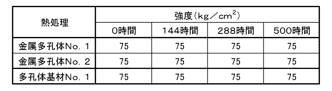
表1より、金属多孔体No.1及び金属多孔体No.2は従来の多孔体基材No.1と同程度の強度を維持できることが確認できた。
From Table 1, porous metal body No. No. 1 and porous metal No. 1 No. 2 is a conventional porous substrate No. It was confirmed that the same level of strength as 1 could be maintained.
(抵抗測定)
強度測定を行なった場合と同様にして金属多孔体No.1、金属多孔体No.2及び多孔体基材No.1を熱処理した。
熱処理後の金属多孔体No.1、金属多孔体No.2及び多孔体基材No.1について、電気抵抗の測定を行なった。
電気抵抗の測定は、試験片の大きさを4cm×4cmとし、四端子法にて、800℃で厚み方向の電気抵抗を測定した。その結果を表2に示す。 (Resistance measurement)
As in the case of strength measurement, porous metal body No. 1 1, porous metal body No. 1 2 and porous substrate No. 1 1 was heat treated.
No. Metal porous body No. 2 after heat treatment. 1, porous metal body No. 1 2 and porous substrate No. 1 The electrical resistance of 1 was measured.
In the measurement of the electrical resistance, the size of the test piece was 4 cm × 4 cm, and the electrical resistance in the thickness direction was measured at 800 ° C. by the four probe method. The results are shown in Table 2.

表2より、金属多孔体No.1及び金属多孔体No.2は従来の多孔体基材No.1と比べて、800℃の高温下では極めて低い抵抗値を示し、SOFCの集電体としても好適に用いることができることが示された。
From Table 2, porous metal body No. No. 1 and porous metal No. 1 No. 2 is a conventional porous substrate No. It showed extremely low resistance at a high temperature of 800 ° C., compared to 1 and showed that it can be suitably used as a current collector of SOFC.
10 金属多孔体
11 コバルト層
12 合金層
13 骨格
14 骨格の内部
15 気孔部
80 多孔体基材
82 合金層
83 骨格
84 骨格の内部
85 気孔部 DESCRIPTION OFSYMBOLS 10 metal porous body 11 cobalt layer 12 alloy layer 13 frame | skeleton 14 framework inside 15 pore part 80 porous material base material 82 alloy layer 83 framework 84 frame interior 85 pore part
11 コバルト層
12 合金層
13 骨格
14 骨格の内部
15 気孔部
80 多孔体基材
82 合金層
83 骨格
84 骨格の内部
85 気孔部 DESCRIPTION OF
Claims (10)
- 連続気孔を有する平板状の金属多孔体であって、
前記金属多孔体の骨格は、ニッケルと、クロム及びスズの少なくとも一方と、を含有する合金層を有し、前記合金層の表面にコバルト層が形成されている、
金属多孔体。 A flat metal porous body having continuous pores,
The skeleton of the porous metal body has an alloy layer containing nickel and at least one of chromium and tin, and a cobalt layer is formed on the surface of the alloy layer.
Porous metal body. - 前記コバルト層は、平均膜厚が1μm以上である、請求項1に記載の金属多孔体。 The metal porous body according to claim 1, wherein the cobalt layer has an average film thickness of 1 μm or more.
- 前記合金層は、Niを主成分とするNiSn合金、Niを主成分とするNiCr合金又はNiを主成分とするNiSnCr合金である、請求項1又は請求項2に記載の金属多孔体。 The metal porous body according to claim 1 or 2, wherein the alloy layer is a NiSn alloy containing Ni as a main component, a NiCr alloy containing Ni as a main component, or a NiSnCr alloy containing Ni as a main component.
- 前記骨格の形状が三次元網目状構造である、請求項1から請求項3のいずれか一項に記載の金属多孔体。 The metal porous body according to any one of claims 1 to 3, wherein the shape of the skeleton is a three-dimensional network structure.
- 前記金属多孔体は、気孔率が60%以上、98%以下である、請求項1から請求項4のいずれか一項に記載の金属多孔体。 The metal porous body according to any one of claims 1 to 4, wherein the porosity of the metal porous body is 60% or more and 98% or less.
- 前記金属多孔体は、平均気孔径が50μm以上、5000μm以下である、請求項1から請求項5のいずれか一項に記載の金属多孔体。 The metal porous body according to any one of claims 1 to 5, wherein the metal porous body has an average pore diameter of 50 μm or more and 5000 μm or less.
- 前記金属多孔体は、厚みが500μm以上、5000μm以下である、請求項1から請求項6のいずれか一項に記載の金属多孔体。 The metal porous body according to any one of claims 1 to 6, wherein the metal porous body has a thickness of 500 μm or more and 5000 μm or less.
- 請求項1から請求項7のいずれか一項に記載の金属多孔体をガス拡散層として備える、固体酸化物型燃料電池。 A solid oxide fuel cell comprising the porous metal body according to any one of claims 1 to 7 as a gas diffusion layer.
- 金属多孔体を製造する方法であって、
連続気孔を有する平板状の多孔体基材を用意する工程と、
前記多孔体基材の骨格の表面全体にコバルトをめっきする工程と、
を有し、
前記多孔体基材の骨格は、ニッケルと、クロム及びスズの少なくとも一方と、を含有する合金層を有する、
金属多孔体の製造方法。 A method of producing a porous metal body, comprising
Providing a flat porous substrate having continuous pores;
Plating cobalt on the entire surface of the skeleton of the porous substrate;
Have
The skeleton of the porous substrate has an alloy layer containing nickel and at least one of chromium and tin,
Method of manufacturing porous metal body. - 前記多孔体基材の骨格の形状が三次元網目状構造である、請求項9に記載の金属多孔体の製造方法。 The manufacturing method of the metal porous body of Claim 9 whose shape of frame | skeleton of the said porous body base material is a three-dimensional network-like structure.
Priority Applications (5)
| Application Number | Priority Date | Filing Date | Title |
|---|---|---|---|
| CN201880045689.6A CN110870117B (en) | 2017-07-14 | 2018-06-22 | Porous metal body, solid oxide fuel cell, and method for producing porous metal body |
| JP2019529024A JP7021669B2 (en) | 2017-07-14 | 2018-06-22 | Method for manufacturing metal porous body, solid oxide fuel cell and metal porous body |
| KR1020207000467A KR20200029439A (en) | 2017-07-14 | 2018-06-22 | Metal porous body, solid oxide fuel cell, and method for manufacturing metal porous body |
| EP18831395.1A EP3654428A4 (en) | 2017-07-14 | 2018-06-22 | Metal porous body, solid oxide fuel cell and method for manufacturing said metal porous body |
| US16/625,392 US20210249666A1 (en) | 2017-07-14 | 2018-06-22 | Metal porous body, solid oxide fuel cell, and method for producing metal porous body |
Applications Claiming Priority (2)
| Application Number | Priority Date | Filing Date | Title |
|---|---|---|---|
| JP2017138140 | 2017-07-14 | ||
| JP2017-138140 | 2017-07-14 |
Publications (1)
| Publication Number | Publication Date |
|---|---|
| WO2019012948A1 true WO2019012948A1 (en) | 2019-01-17 |
Family
ID=65002032
Family Applications (1)
| Application Number | Title | Priority Date | Filing Date |
|---|---|---|---|
| PCT/JP2018/023725 WO2019012948A1 (en) | 2017-07-14 | 2018-06-22 | Metal porous body, solid oxide fuel cell and method for manufacturing said metal porous body |
Country Status (6)
| Country | Link |
|---|---|
| US (1) | US20210249666A1 (en) |
| EP (1) | EP3654428A4 (en) |
| JP (1) | JP7021669B2 (en) |
| KR (1) | KR20200029439A (en) |
| CN (1) | CN110870117B (en) |
| WO (1) | WO2019012948A1 (en) |
Cited By (3)
| Publication number | Priority date | Publication date | Assignee | Title |
|---|---|---|---|---|
| JPWO2020217668A1 (en) * | 2019-04-25 | 2020-10-29 | ||
| WO2020235265A1 (en) * | 2019-05-22 | 2020-11-26 | 住友電気工業株式会社 | Porous body, fuel cell including same, and water-vapor electrolysis apparatus including same |
| EP3797901B1 (en) | 2019-09-25 | 2021-09-08 | Evonik Operations GmbH | Metal foam body and method for its production |
Families Citing this family (1)
| Publication number | Priority date | Publication date | Assignee | Title |
|---|---|---|---|---|
| EP3499615A4 (en) | 2017-10-25 | 2020-02-05 | Sumitomo Electric Toyama Co., Ltd. | Fuel cell and method for manufacturing metal porous body |
Citations (7)
| Publication number | Priority date | Publication date | Assignee | Title |
|---|---|---|---|---|
| JPH11154517A (en) | 1997-11-21 | 1999-06-08 | Inoac Corporation:Kk | Metallic porous body for secondary battery and its manufacture |
| JP2006092837A (en) * | 2004-09-22 | 2006-04-06 | Kyocera Corp | Current collecting member for fuel cell, its manufacturing method, fuel cell stack using it and the fuel cell |
| JP2011192546A (en) * | 2010-03-15 | 2011-09-29 | Osaka Gas Co Ltd | Manufacturing method of interconnector for fuel cell |
| JP2012132083A (en) | 2010-12-24 | 2012-07-12 | Sumitomo Electric Ind Ltd | Metallic porous body having high corrosion resistance, and method for manufacturing therefor |
| JP2012149282A (en) | 2011-01-17 | 2012-08-09 | Toyama Sumitomo Denko Kk | Porous metal having high corrosion resistance, and process for producing the same |
| JP2013093271A (en) * | 2011-10-27 | 2013-05-16 | Sumitomo Electric Ind Ltd | Porous collector and fuel cell using the same |
| JP2017138140A (en) | 2016-02-02 | 2017-08-10 | 株式会社ブイ・テクノロジー | Manufacturing method of radiation detector |
Family Cites Families (4)
| Publication number | Priority date | Publication date | Assignee | Title |
|---|---|---|---|---|
| CN100565987C (en) * | 2000-11-16 | 2009-12-02 | 三菱综合材料株式会社 | The air electrode current collector that solid electrolyte fuel cell uses |
| JP2015159021A (en) * | 2014-02-24 | 2015-09-03 | 住友電気工業株式会社 | Porous collector and electrochemical device |
| JP6614131B2 (en) * | 2014-03-12 | 2019-12-04 | 住友電気工業株式会社 | Porous current collector, fuel cell, and method for producing porous current collector |
| CN106334561A (en) * | 2016-09-07 | 2017-01-18 | 江苏师范大学 | Non-noble metal catalyst for alcoholysis hydrogen production of sodium borohydride and preparation method of non-noble metal catalyst for alcoholysis hydrogen production of sodium borohydride |
-
2018
- 2018-06-22 KR KR1020207000467A patent/KR20200029439A/en unknown
- 2018-06-22 WO PCT/JP2018/023725 patent/WO2019012948A1/en unknown
- 2018-06-22 CN CN201880045689.6A patent/CN110870117B/en active Active
- 2018-06-22 EP EP18831395.1A patent/EP3654428A4/en active Pending
- 2018-06-22 JP JP2019529024A patent/JP7021669B2/en active Active
- 2018-06-22 US US16/625,392 patent/US20210249666A1/en not_active Abandoned
Patent Citations (7)
| Publication number | Priority date | Publication date | Assignee | Title |
|---|---|---|---|---|
| JPH11154517A (en) | 1997-11-21 | 1999-06-08 | Inoac Corporation:Kk | Metallic porous body for secondary battery and its manufacture |
| JP2006092837A (en) * | 2004-09-22 | 2006-04-06 | Kyocera Corp | Current collecting member for fuel cell, its manufacturing method, fuel cell stack using it and the fuel cell |
| JP2011192546A (en) * | 2010-03-15 | 2011-09-29 | Osaka Gas Co Ltd | Manufacturing method of interconnector for fuel cell |
| JP2012132083A (en) | 2010-12-24 | 2012-07-12 | Sumitomo Electric Ind Ltd | Metallic porous body having high corrosion resistance, and method for manufacturing therefor |
| JP2012149282A (en) | 2011-01-17 | 2012-08-09 | Toyama Sumitomo Denko Kk | Porous metal having high corrosion resistance, and process for producing the same |
| JP2013093271A (en) * | 2011-10-27 | 2013-05-16 | Sumitomo Electric Ind Ltd | Porous collector and fuel cell using the same |
| JP2017138140A (en) | 2016-02-02 | 2017-08-10 | 株式会社ブイ・テクノロジー | Manufacturing method of radiation detector |
Non-Patent Citations (1)
| Title |
|---|
| See also references of EP3654428A4 |
Cited By (4)
| Publication number | Priority date | Publication date | Assignee | Title |
|---|---|---|---|---|
| JPWO2020217668A1 (en) * | 2019-04-25 | 2020-10-29 | ||
| WO2020217668A1 (en) * | 2019-04-25 | 2020-10-29 | 富山住友電工株式会社 | Metal porous body, electrode for electrolysis, hydrogen production device, fuel cell, and method for producing metal porous body |
| WO2020235265A1 (en) * | 2019-05-22 | 2020-11-26 | 住友電気工業株式会社 | Porous body, fuel cell including same, and water-vapor electrolysis apparatus including same |
| EP3797901B1 (en) | 2019-09-25 | 2021-09-08 | Evonik Operations GmbH | Metal foam body and method for its production |
Also Published As
| Publication number | Publication date |
|---|---|
| US20210249666A1 (en) | 2021-08-12 |
| JPWO2019012948A1 (en) | 2020-05-21 |
| KR20200029439A (en) | 2020-03-18 |
| CN110870117B (en) | 2023-04-04 |
| EP3654428A1 (en) | 2020-05-20 |
| EP3654428A4 (en) | 2021-04-07 |
| CN110870117A (en) | 2020-03-06 |
| JP7021669B2 (en) | 2022-02-17 |
Similar Documents
| Publication | Publication Date | Title |
|---|---|---|
| Yuan et al. | Bubble evolution and transport in PEM water electrolysis: Mechanism, impact, and management | |
| Stiber et al. | A high-performance, durable and low-cost proton exchange membrane electrolyser with stainless steel components | |
| Wei et al. | A hierarchically porous nickel–copper phosphide nano-foam for efficient electrochemical splitting of water | |
| Carmo et al. | A comprehensive review on PEM water electrolysis | |
| JP7021669B2 (en) | Method for manufacturing metal porous body, solid oxide fuel cell and metal porous body | |
| Majasan et al. | Effect of microstructure of porous transport layer on performance in polymer electrolyte membrane water electrolyser | |
| JP6663584B2 (en) | Porous metal body, fuel cell, and method for manufacturing porous metal body | |
| JP6300315B2 (en) | Fuel cell current collector and fuel cell | |
| US11316172B2 (en) | Fuel cell and method of manufacturing metal porous body | |
| KR20180037174A (en) | Porous metal body, fuel cell, and method for producing porous metal body | |
| Yuan et al. | The porous transport layer in proton exchange membrane water electrolysis: perspectives on a complex component | |
| Koj et al. | Novel alkaline water electrolysis with nickel-iron gas diffusion electrode for oxygen evolution | |
| WO2017022542A1 (en) | Metal porous body, fuel cell, and method for manufacturing metal porous body | |
| CN107208294B (en) | The manufacturing method of nickel alloy porous body | |
| US11434547B2 (en) | Metal porous material, fuel cell, and method of producing metal porous material | |
| WO2019012947A1 (en) | Metal porous body, solid oxide fuel cell and method for manufacturing said metal porous body | |
| WO2020217668A1 (en) | Metal porous body, electrode for electrolysis, hydrogen production device, fuel cell, and method for producing metal porous body | |
| WO2019106879A1 (en) | Metallic porous body, fuel cell, and method for producing metallic porous body | |
| JP6812606B1 (en) | Porous materials, electrochemical cells, and methods for producing porous materials | |
| US20230143743A1 (en) | Titanium substrate, method for producing titanium substrate, electrode for water electrolysis, and water electrolysis apparatus | |
| WO2022210421A1 (en) | Titanium porous plate, electrode for water electrolysis, and water electrolysis device | |
| JP2004039517A (en) | Porous metal gas diffusion sheet for solid macromolecular fuel cell exhibiting outstanding contact surface conductivity for a long period of time | |
| JP2019220465A (en) | Electrolyte for electrochemical cell and electrochemical cell |
Legal Events
| Date | Code | Title | Description |
|---|---|---|---|
| 121 | Ep: the epo has been informed by wipo that ep was designated in this application |
Ref document number: 18831395 Country of ref document: EP Kind code of ref document: A1 |
|
| ENP | Entry into the national phase |
Ref document number: 2019529024 Country of ref document: JP Kind code of ref document: A |
|
| NENP | Non-entry into the national phase |
Ref country code: DE |
|
| ENP | Entry into the national phase |
Ref document number: 2018831395 Country of ref document: EP Effective date: 20200214 |