WO2019009331A1 - タービン翼及びガスタービン - Google Patents
タービン翼及びガスタービン Download PDFInfo
- Publication number
- WO2019009331A1 WO2019009331A1 PCT/JP2018/025385 JP2018025385W WO2019009331A1 WO 2019009331 A1 WO2019009331 A1 WO 2019009331A1 JP 2018025385 W JP2018025385 W JP 2018025385W WO 2019009331 A1 WO2019009331 A1 WO 2019009331A1
- Authority
- WO
- WIPO (PCT)
- Prior art keywords
- wing
- cooling
- height direction
- region
- cooling holes
- Prior art date
- Legal status (The legal status is an assumption and is not a legal conclusion. Google has not performed a legal analysis and makes no representation as to the accuracy of the status listed.)
- Ceased
Links
Images









Classifications
-
- F—MECHANICAL ENGINEERING; LIGHTING; HEATING; WEAPONS; BLASTING
- F01—MACHINES OR ENGINES IN GENERAL; ENGINE PLANTS IN GENERAL; STEAM ENGINES
- F01D—NON-POSITIVE DISPLACEMENT MACHINES OR ENGINES, e.g. STEAM TURBINES
- F01D5/00—Blades; Blade-carrying members; Heating, heat-insulating, cooling or antivibration means on the blades or the members
- F01D5/12—Blades
- F01D5/14—Form or construction
- F01D5/18—Hollow blades, i.e. blades with cooling or heating channels or cavities; Heating, heat-insulating or cooling means on blades
- F01D5/187—Convection cooling
-
- F—MECHANICAL ENGINEERING; LIGHTING; HEATING; WEAPONS; BLASTING
- F01—MACHINES OR ENGINES IN GENERAL; ENGINE PLANTS IN GENERAL; STEAM ENGINES
- F01D—NON-POSITIVE DISPLACEMENT MACHINES OR ENGINES, e.g. STEAM TURBINES
- F01D25/00—Component parts, details, or accessories, not provided for in, or of interest apart from, other groups
- F01D25/08—Cooling; Heating; Heat-insulation
- F01D25/12—Cooling
-
- F—MECHANICAL ENGINEERING; LIGHTING; HEATING; WEAPONS; BLASTING
- F01—MACHINES OR ENGINES IN GENERAL; ENGINE PLANTS IN GENERAL; STEAM ENGINES
- F01D—NON-POSITIVE DISPLACEMENT MACHINES OR ENGINES, e.g. STEAM TURBINES
- F01D5/00—Blades; Blade-carrying members; Heating, heat-insulating, cooling or antivibration means on the blades or the members
- F01D5/12—Blades
- F01D5/14—Form or construction
- F01D5/18—Hollow blades, i.e. blades with cooling or heating channels or cavities; Heating, heat-insulating or cooling means on blades
-
- F—MECHANICAL ENGINEERING; LIGHTING; HEATING; WEAPONS; BLASTING
- F01—MACHINES OR ENGINES IN GENERAL; ENGINE PLANTS IN GENERAL; STEAM ENGINES
- F01D—NON-POSITIVE DISPLACEMENT MACHINES OR ENGINES, e.g. STEAM TURBINES
- F01D9/00—Stators
- F01D9/02—Nozzles; Nozzle boxes; Stator blades; Guide conduits, e.g. individual nozzles
-
- F—MECHANICAL ENGINEERING; LIGHTING; HEATING; WEAPONS; BLASTING
- F01—MACHINES OR ENGINES IN GENERAL; ENGINE PLANTS IN GENERAL; STEAM ENGINES
- F01D—NON-POSITIVE DISPLACEMENT MACHINES OR ENGINES, e.g. STEAM TURBINES
- F01D9/00—Stators
- F01D9/02—Nozzles; Nozzle boxes; Stator blades; Guide conduits, e.g. individual nozzles
- F01D9/023—Transition ducts between combustor cans and first stage of the turbine in gas-turbine engines; their cooling or sealings
-
- F—MECHANICAL ENGINEERING; LIGHTING; HEATING; WEAPONS; BLASTING
- F01—MACHINES OR ENGINES IN GENERAL; ENGINE PLANTS IN GENERAL; STEAM ENGINES
- F01D—NON-POSITIVE DISPLACEMENT MACHINES OR ENGINES, e.g. STEAM TURBINES
- F01D9/00—Stators
- F01D9/06—Fluid supply conduits to nozzles or the like
- F01D9/065—Fluid supply or removal conduits traversing the working fluid flow, e.g. for lubrication-, cooling-, or sealing fluids
-
- F—MECHANICAL ENGINEERING; LIGHTING; HEATING; WEAPONS; BLASTING
- F02—COMBUSTION ENGINES; HOT-GAS OR COMBUSTION-PRODUCT ENGINE PLANTS
- F02C—GAS-TURBINE PLANTS; AIR INTAKES FOR JET-PROPULSION PLANTS; CONTROLLING FUEL SUPPLY IN AIR-BREATHING JET-PROPULSION PLANTS
- F02C7/00—Features, components parts, details or accessories, not provided for in, or of interest apart form groups F02C1/00 - F02C6/00; Air intakes for jet-propulsion plants
- F02C7/12—Cooling of plants
- F02C7/16—Cooling of plants characterised by cooling medium
- F02C7/18—Cooling of plants characterised by cooling medium the medium being gaseous, e.g. air
-
- F—MECHANICAL ENGINEERING; LIGHTING; HEATING; WEAPONS; BLASTING
- F05—INDEXING SCHEMES RELATING TO ENGINES OR PUMPS IN VARIOUS SUBCLASSES OF CLASSES F01-F04
- F05D—INDEXING SCHEME FOR ASPECTS RELATING TO NON-POSITIVE-DISPLACEMENT MACHINES OR ENGINES, GAS-TURBINES OR JET-PROPULSION PLANTS
- F05D2220/00—Application
- F05D2220/30—Application in turbines
- F05D2220/32—Application in turbines in gas turbines
-
- F—MECHANICAL ENGINEERING; LIGHTING; HEATING; WEAPONS; BLASTING
- F05—INDEXING SCHEMES RELATING TO ENGINES OR PUMPS IN VARIOUS SUBCLASSES OF CLASSES F01-F04
- F05D—INDEXING SCHEME FOR ASPECTS RELATING TO NON-POSITIVE-DISPLACEMENT MACHINES OR ENGINES, GAS-TURBINES OR JET-PROPULSION PLANTS
- F05D2240/00—Components
- F05D2240/10—Stators
- F05D2240/12—Fluid guiding means, e.g. vanes
- F05D2240/122—Fluid guiding means, e.g. vanes related to the trailing edge of a stator vane
-
- F—MECHANICAL ENGINEERING; LIGHTING; HEATING; WEAPONS; BLASTING
- F05—INDEXING SCHEMES RELATING TO ENGINES OR PUMPS IN VARIOUS SUBCLASSES OF CLASSES F01-F04
- F05D—INDEXING SCHEME FOR ASPECTS RELATING TO NON-POSITIVE-DISPLACEMENT MACHINES OR ENGINES, GAS-TURBINES OR JET-PROPULSION PLANTS
- F05D2240/00—Components
- F05D2240/20—Rotors
- F05D2240/30—Characteristics of rotor blades, i.e. of any element transforming dynamic fluid energy to or from rotational energy and being attached to a rotor
- F05D2240/304—Characteristics of rotor blades, i.e. of any element transforming dynamic fluid energy to or from rotational energy and being attached to a rotor related to the trailing edge of a rotor blade
-
- F—MECHANICAL ENGINEERING; LIGHTING; HEATING; WEAPONS; BLASTING
- F05—INDEXING SCHEMES RELATING TO ENGINES OR PUMPS IN VARIOUS SUBCLASSES OF CLASSES F01-F04
- F05D—INDEXING SCHEME FOR ASPECTS RELATING TO NON-POSITIVE-DISPLACEMENT MACHINES OR ENGINES, GAS-TURBINES OR JET-PROPULSION PLANTS
- F05D2240/00—Components
- F05D2240/20—Rotors
- F05D2240/30—Characteristics of rotor blades, i.e. of any element transforming dynamic fluid energy to or from rotational energy and being attached to a rotor
- F05D2240/307—Characteristics of rotor blades, i.e. of any element transforming dynamic fluid energy to or from rotational energy and being attached to a rotor related to the tip of a rotor blade
-
- F—MECHANICAL ENGINEERING; LIGHTING; HEATING; WEAPONS; BLASTING
- F05—INDEXING SCHEMES RELATING TO ENGINES OR PUMPS IN VARIOUS SUBCLASSES OF CLASSES F01-F04
- F05D—INDEXING SCHEME FOR ASPECTS RELATING TO NON-POSITIVE-DISPLACEMENT MACHINES OR ENGINES, GAS-TURBINES OR JET-PROPULSION PLANTS
- F05D2240/00—Components
- F05D2240/35—Combustors or associated equipment
-
- F—MECHANICAL ENGINEERING; LIGHTING; HEATING; WEAPONS; BLASTING
- F05—INDEXING SCHEMES RELATING TO ENGINES OR PUMPS IN VARIOUS SUBCLASSES OF CLASSES F01-F04
- F05D—INDEXING SCHEME FOR ASPECTS RELATING TO NON-POSITIVE-DISPLACEMENT MACHINES OR ENGINES, GAS-TURBINES OR JET-PROPULSION PLANTS
- F05D2250/00—Geometry
- F05D2250/10—Two-dimensional
- F05D2250/18—Two-dimensional patterned
- F05D2250/185—Two-dimensional patterned serpentine-like
-
- F—MECHANICAL ENGINEERING; LIGHTING; HEATING; WEAPONS; BLASTING
- F05—INDEXING SCHEMES RELATING TO ENGINES OR PUMPS IN VARIOUS SUBCLASSES OF CLASSES F01-F04
- F05D—INDEXING SCHEME FOR ASPECTS RELATING TO NON-POSITIVE-DISPLACEMENT MACHINES OR ENGINES, GAS-TURBINES OR JET-PROPULSION PLANTS
- F05D2260/00—Function
- F05D2260/20—Heat transfer, e.g. cooling
-
- F—MECHANICAL ENGINEERING; LIGHTING; HEATING; WEAPONS; BLASTING
- F05—INDEXING SCHEMES RELATING TO ENGINES OR PUMPS IN VARIOUS SUBCLASSES OF CLASSES F01-F04
- F05D—INDEXING SCHEME FOR ASPECTS RELATING TO NON-POSITIVE-DISPLACEMENT MACHINES OR ENGINES, GAS-TURBINES OR JET-PROPULSION PLANTS
- F05D2260/00—Function
- F05D2260/20—Heat transfer, e.g. cooling
- F05D2260/205—Cooling fluid recirculation, i.e. after cooling one or more components is the cooling fluid recovered and used elsewhere for other purposes
Definitions
- the present disclosure relates to turbine blades and gas turbines.
- Patent Document 1 discloses a turbine blade arranged in a combustion gas flow path of a gas turbine and provided with an internal flow path through which a cooling medium flows.
- a plurality of air outlets are arranged along the direction connecting the blade root and the blade tip, and the air outlets are provided to open at the trailing edge.
- the cooling medium supplied to the internal flow path from the supply port provided at the blade root portion of the turbine moving blade is blown out from the plurality of air outlets provided at the rear edge portion while passing through the internal flow path. It is supposed to be
- Patent Document 1 does not specifically disclose cooling of the turbine blade in accordance with the temperature distribution and / or pressure distribution in the cooling passage.
- At least one embodiment of the present invention aims to provide a turbine blade and a gas turbine that can effectively cool the turbine blade.
- a turbine blade With the wings, A cooling passage extending in the wing height direction inside the wing portion; A plurality of cooling holes formed at the rear edge of the wing so as to be arranged along the wing height direction and in communication with the cooling passage and opening on the surface of the wing at the rear edge; Equipped with An area where the plurality of cooling holes are formed at the trailing edge portion is: A central region including an intermediate position between the first end and the second end of the wing in the wing height direction, and having a constant d_mid as an index indicating the opening density of the plurality of cooling holes; An upstream region located upstream of the cooling medium flow in the cooling passage in the wing height direction than the central region, and having an index indicating the opening density of the plurality of cooling holes constant at d_up; And d_up, which is located downstream of the central flow area in the wing height direction and downstream of the cooling medium flow, and whose index indicating the opening density of the plurality of cooling holes is constant at
- the opening density of the cooling holes is made larger at a position downstream of the flow of the cooling medium in the cooling passage than at a position further upstream, so the temperature of the cooling medium is relatively high.
- the flow rate of the cooling medium supplied through the cooling holes can be increased.
- a turbine blade With the wings, A cooling passage extending in the wing height direction inside the wing portion; An arrangement is made along the wing height direction and is formed at the rear edge so as to convectively cool the rear edge of the wing, and is in communication with the cooling passage and penetrates the rear edge to form a rear edge end face And a plurality of cooling holes open to the An index indicating an opening density of the cooling hole in a central region including an intermediate position between the first end and the second end of the wing in the wing height direction is d_mid, The index in a region located upstream of the cooling medium flow in the cooling passage in the wing height direction with respect to the central region is d_up, Assuming that the index in a region located downstream of the cooling medium flow with respect to the central region in the wing height direction is d_down, the relationship d_up ⁇ d_down ⁇ d_mid is satisfied, An area where the plurality of cooling holes are formed at the trailing edge portion is
- the most upstream area where the index indicating the density is constant at d_up An indicator indicating the opening density of the plurality of cooling holes, which is located on the downstream side of the cooling medium flow with respect to the central area in the wing height direction and on the most downstream side of the cooling medium flow in the formation area And the most downstream area where d_down is constant.
- the temperature of the gas flowing through the combustion gas flow path in which the turbine blade is disposed is higher in the central region in the blade height direction than in the region on both ends (first end and second end) of the blade portion Tend.
- the cooling passage formed inside the wing since the cooling medium flows while cooling the wing, a temperature distribution may be generated which becomes higher toward the downstream side of the flow of the cooling medium.
- the flow rate of the cooling medium through the cooling holes in the central region in the blade height direction is maximized, and the cooling medium flow downstream of the cooling passage It is desirable that the flow rate of the cooling medium through the cooling holes be larger than the area located upstream in the area located in the area.
- the opening density of the cooling holes in the central region can be divided into a region (upstream region) located upstream of the central region and a region (downstream region) located downstream Since the opening density of the cooling holes in the above is increased, the supply flow rate of the cooling medium through the cooling holes can be increased in the central region where the gas temperature flowing through the combustion gas flow path becomes relatively high. Further, in the configuration of the above (2), in the downstream region described above, the opening density of the cooling holes is increased compared to the upstream region described above, so in the downstream region where the temperature of the cooling medium becomes higher than the upstream region. , The supply flow rate of the cooling medium through the cooling holes can be increased. Thus, depending on the temperature distribution of the cooling passage, the trailing edge of the turbine blade can be properly cooled.
- a turbine blade With the wings, A cooling passage extending in the wing height direction inside the wing portion; A plurality of cooling holes formed at the rear edge of the wing so as to be arranged along the wing height direction and in communication with the cooling passage and opening on the surface of the wing at the rear edge; A turbine blade comprising The turbine blade is a moving blade, An index indicating the opening density of the cooling hole in the central area including the middle position between the tip and the base of the wing in the wing height direction is d_mid, and the tip side is more than the central area in the wing height direction.
- the index in the region located at is d_tip, Assuming that the index in the region located on the proximal side with respect to the central region in the wing height direction is d_root, the relationship of d_tip ⁇ d_mid ⁇ d_root is satisfied,
- the index d_tip, d_mid and d_root indicating the opening density is the ratio of the through hole diameter D of the cooling hole provided to penetrate the trailing edge to the pitch P between the cooling holes adjacent in the wing height direction D / P,
- An area where the plurality of cooling holes are formed at the trailing edge portion is: A central region including an intermediate position between the tip end and the base end of the wing in the wing height direction, and having a constant d_mid as an index indicating the opening density of the plurality of cooling holes;
- a turbine blade With the wings, A cooling passage extending in the wing height direction inside the wing portion; An arrangement is made along the wing height direction and is formed at the rear edge so as to convectively cool the rear edge of the wing, and is in communication with the cooling passage and penetrates the rear edge to form a rear edge end face With multiple cooling holes, A turbine blade comprising The turbine blade is a moving blade, An index indicating the opening density of the cooling hole in the central area including the middle position between the tip and the base of the wing in the wing height direction is d_mid, and the tip side is more than the central area in the wing height direction.
- An area where the plurality of cooling holes are formed at the trailing edge portion is: A central region including an intermediate position between the tip end and the base end of the wing in the wing height direction, and having a constant d_mid as an index indicating the opening density of the plurality of cooling holes; A tip which is located closer to the tip end of the formation region than the central region in the wing height direction and closer to the tip among the formation regions, and whose index indicating the opening density of the plurality of cooling holes is constant at d_tip Side area, An index indicating the opening density of the plurality of cooling holes is constant at d_root, which is located on the proximal end side of the central region in the wing height direction and closer to the proximal end of the formation regions than the
- the temperature of the gas flowing through the combustion gas flow path in which the moving blades (turbine blades) are disposed is higher in the central region in the blade height direction than in the region on both ends (tip and base end) of the blade portion Tend to be
- the centrifugal force acts on the cooling medium in the cooling passage formed inside the blade of the moving blade, so the pressure distribution becomes higher toward the tip of the blade in the cooling passage. It may occur.
- the flow rate of the cooling medium through the cooling holes in the central region in the blade height direction is maximized, and the tip end side in the blade height direction is located.
- the opening density of the cooling holes in the central region can be divided into a region (distal end region) located distal to the central region and a region (proximal end) Since the opening density of the cooling holes in the side area is made larger, the supply flow rate of the cooling medium via the cooling holes can be increased in the central area where the gas temperature flowing through the combustion gas flow path becomes relatively high.
- the opening density of the cooling holes is made smaller in the above-mentioned tip side region compared to the above-mentioned base end side region, and therefore, the tip side is It is possible to reduce the variation in the flow rate of the cooling medium supplied through the cooling holes between the area and the proximal area.
- the trailing edge of the turbine blade can be properly cooled.
- the central region includes a plurality of cooling holes of the same diameter
- the tip side area located closer to the tip end side of the wing than the central area and the proximal side area located closer to the base end of the wing than the central area have a plurality of coolings of the same diameter as the cooling holes in the central area Including holes.
- the surface of the wing is an end face of the trailing edge.
- the plurality of cooling holes are formed to be inclined with respect to a plane orthogonal to the wing height direction. .
- the cooling holes are formed with an inclination with respect to the plane orthogonal to the wing height direction, the cooling holes are formed parallel to the plane orthogonal to the wing height direction
- the cooling holes can be made longer than in the case of This can effectively cool the trailing edge of the turbine blade.
- the plurality of cooling holes are formed in parallel to one another.
- the cooling passage is a final one of serpentine flow passages formed inside the wing.
- the rear edge portion of the turbine blade is properly cooled by opening the plurality of cooling holes communicating with the final path of the serpentine flow path on the surface of the wing portion at the rear edge portion. be able to.
- the turbine blade is a moving blade
- An outlet opening of the cooling passage is formed on the tip end side of the wing portion.
- the turbine blade is a stationary blade
- An outlet opening of the cooling passage is formed on the inner shroud side of the wing.
- the stationary blade as the turbine blade since the stationary blade as the turbine blade has the configuration of the above (1) or (2), the trailing edge portion of the stationary blade as the turbine blade can be appropriately cooled.
- a gas turbine according to at least one embodiment of the present invention, The turbine blade according to any one of the above (1) to (11); And a combustor for generating a combustion gas flowing in a combustion gas flow path provided with the turbine blade.
- the turbine blade since the turbine blade has any one of the configurations (1) to (11), the trailing edge of the turbine blade can be properly cooled.
- a turbine blade and a gas turbine capable of effectively cooling the turbine blade are provided.
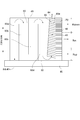
- FIG. 1 is a partial cross-sectional view of a moving blade that is a turbine blade according to an embodiment. It is a III-III cross section of the moving blade (turbine blade) shown in FIG.
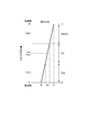
- FIG. 3 is a schematic cross-sectional view of a moving blade (turbine blade) shown in FIG. It is a typical sectional view of a stator blade which is a turbine blade concerning one embodiment. It is a graph which shows an example of distribution of the opening density of the trailing edge of a moving blade (turbine blade) in one embodiment. It is a graph which shows an example of distribution of the opening density of the trailing edge of a moving blade (turbine blade) in one embodiment.
- FIG. 3 is a cross-sectional view of a trailing edge of a turbine blade according to an embodiment taken along the blade height direction.
- FIG. 3 is a view of a trailing edge of a turbine blade according to an embodiment as viewed from the trailing edge of the blade toward the leading edge.
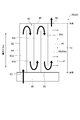
- It is a schematic diagram which shows the structure of the cooling passage of the turbine rotor blade in one Embodiment. It is a schematic diagram which shows the structure of the turbulator in one Embodiment.
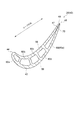
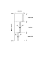
- FIG. 1 It is a schematic diagram of the turbine bucket explaining the basic composition of the present invention. It is a figure which shows opening density distribution of the cooling hole of the conventional wing
- the moving blade 26 of the gas terpin is fixed to the rotor 8 rotating at high speed (see FIG. 1), and cools the wing portion 42 using a cooling medium in order to operate in a high temperature combustion gas atmosphere.
- a cooling passage 66 is formed inside the wing portion 42 of the moving blade 26, and the cooling medium supplied from the proximal end 50 flows in the cooling passage 66 to cool the wing portion 42.
- the cooling medium flows through the final path 60 e and is supplied to the plurality of cooling holes 70 formed on the downstream side of the rotor 8 in the axial direction of the trailing edge 47 and having an opening at the trailing edge 46.
- the cooling medium convectively cools the trailing edge 47 in the process of flowing through the cooling holes 70 and discharging into the combustion gas.
- FIG. 20B in the cooling holes disclosed in Patent Document 1, the cooling holes 70 having the same diameter are arranged at the same pitch over the entire length of the trailing edge 47 in the blade height direction, The opening density of the cooling holes 70 is made uniform in the wing height direction.
- This example is an example of the conventional arrangement of cooling holes.
- the cooling medium is heated from the wings 42 in the process of flowing through the cooling passage 66 upstream of the final pass 60 e and flows into the final pass 60 e on the trailing edge 46 side.
- the cooling medium receives heat from the wings 42 and is further heated up in the process of flowing from the proximal end 50 on the inlet side to the distal end 48 on the outlet side of the final pass 60 e in the flow direction. Therefore, the temperature of the wing portion 42 in the tip end region of the cooling medium flowing through the final pass 60 e may be high, which may cause severe use conditions.
- the tip side region of the blade height direction outer side (radial direction outer side) of the blade portion 42 becomes a metal temperature close to the use limit temperature determined from the oxidation reduction allowance and does not exceed the use limit temperature It is necessary to cool the wings 42.
- the metal temperature is highest at the tip end region of the final pass 60e of the wing portion 42, and the center region of the wing portion 42 is lower than the tip end region.
- the side area is lower than the central area.
- the blade portion 42 are arranged in the blade height direction so that the metal temperature distribution is uniform without increasing the metal temperature variation in each region. It is desirable to select the opening density of the cooling holes 70. That is, the opening density of the cooling holes 70 on the tip side area outside the blade height direction of the moving blade 26 in the downstream side area in the flow direction of the cooling medium is the most dense distribution. It is desirable that the opening density be an intermediate distribution, and the distribution be the sparsest in the cooling holes 70 in the proximal region. Based on the above-mentioned view, an example of a schematic view of a cooling hole as one embodiment according to the present invention is shown in FIG. 20C.
- FIG. 20E shows an example of a creep limit curve of a wing material.
- the vertical axis shows allowable stress
- the horizontal axis shows metal temperature. It becomes a downward curve where the allowable stress decreases with increasing metal temperature.
- the wing portion 42 In the region where the stress below the creep limit curve is small, creep rupture of the wing portion 42 does not occur, but in the region where the stress above the curve is large, the wing portion 42 may be damaged by creep rupture. .
- the distal end region of the wing portion 42 does not cause creep rupture because the centrifugal force acting on it is small, but creep rupture is possible even if the central region and the proximal end region of the wing portion 42 have a lower metal temperature than the distal end region. It is necessary to consider the nature.
- FIG. 20D and FIG. 20E show an example where the creep strength of the central region and the proximal region is critical.
- FIG. 20E an A1 point in the central region and a B1 point in the proximal region will be described as an example.
- the point A1 indicates that the creep limit is exceeded
- the point B1 indicates that the creep limit is within. Whether or not it falls within the creep limit depends on the size of the wing, the wall thickness, the metal temperature, etc., at the relevant site.
- the creep limit is exceeded, so it is necessary to lower the metal temperature.
- the opening density of the cooling holes 70 in the central region is made denser to strengthen the cooling, and the metal temperature at the point A2 is lowered.
- the opening density of the cooling holes 70 in the central region is increased, the flow rate of the cooling medium flowing through the cooling holes 70 in the central region increases, and the flow rate of the cooling medium flowing through the cooling holes 70 in the proximal end region may decrease. There is sex. Therefore, when the cooling of the central region is strengthened, the metal temperature of the proximal region rises to the point B2, but if the position of the point B2 is within the creep limit as shown in FIG. 20E, this opening density is selected do it.
- the distal region can be adjusted as well.
- the flow rate of the cooling medium flowing through the cooling holes 70 in the front end region can be reduced by reducing the opening density of the cooling holes 70 in the front end region.
- the flow rate of the cooling medium flowing through the cooling holes 70 in the central area can be increased to enhance the cooling of the central area .
- FIG. 20D An example in which the opening density of the cooling holes 70 is corrected by such a procedure is shown in FIG. 20D.
- the solid line is the aperture density after adjustment
- the dashed line is the aperture density before adjustment. It can be confirmed that each of the regions is within the operating limit temperature or the creep limit, and the appropriate opening density of the cooling holes in each region can be determined.
- the centrifugal force acting on the cooling medium flowing in the final pass 60 e It may affect the placement of 70.
- An example is described below.
- a centrifugal force acts on the cooling medium flowing in the final path 60e of the wing portion 42 in the same direction as the flow direction of the cooling medium. That is, due to the action of the centrifugal force, a pressure gradient is generated in the cooling medium in which the pressure increases from the proximal end 50 to the distal end 48. Accordingly, in the arrangement of the cooling holes having a uniform opening density shown in FIG.
- the flow rate of the cooling medium discharged into the combustion gas from the cooling holes 70 of the outlet opening 64 of the tip 48 of the wing portion 42 As a result, the flow rate of the cooling medium supplied to the cooling holes 70 in the central region and the proximal region may decrease, and the central region and the proximal region may become insufficiently cooled.
- the opening density is reduced stepwise from the proximal end region toward the distal end region, and the exhaust gas is discharged from the outlet opening 64 on the distal end 48 side or into the combustion gas from the cooling holes 70 on the distal end region. It is necessary to throttle the flow rate of the medium to increase the amount of cooling medium supplied to the cooling holes 70 in the central and proximal regions.
- the metal temperature of each region can be made uniform.
- FIG. 20F shows an example of the opening density distribution of the cooling holes 70 in consideration of the influence of the centrifugal force.
- FIG. 1 is a schematic configuration diagram of a gas turbine to which a turbine blade according to an embodiment is applied.
- the gas turbine 1 is rotationally driven by the compressor 2 for generating compressed air, a combustor 4 for generating combustion gas using the compressed air and fuel, and the combustion gas.
- a turbine 6 configured as described above.
- a generator (not shown) is connected to the turbine 6.
- the compressor 2 includes a plurality of stationary blades 16 fixed to the compressor casing 10 and a plurality of moving blades 18 implanted in the rotor 8 so as to be alternately arranged with respect to the stationary blades 16. .
- the air taken in from the air intake 12 is sent to the compressor 2, and this air is compressed by passing through the plurality of stationary blades 16 and the plurality of moving blades 18. Become compressed air.
- a fuel and compressed air generated by the compressor 2 are supplied to the combustor 4, and the fuel is burned in the combustor 4 to generate a combustion gas which is a working fluid of the turbine 6. Be done.
- a plurality of combustors 4 may be disposed in the casing 20 along the circumferential direction centering on the rotor.
- the turbine 6 has a combustion gas flow passage 28 formed in the turbine casing 22, and includes a plurality of stationary blades 24 and moving blades 26 provided in the combustion gas flow passage 28.
- the stator vanes 24 are fixed to the turbine casing 22 side, and a plurality of stator vanes 24 arranged along the circumferential direction of the rotor 8 constitute a stator vane row.
- the moving blades 26 are implanted in the rotor 8, and a plurality of moving blades 26 arranged along the circumferential direction of the rotor 8 constitute a moving blade row.
- the stationary blade row and the moving blade row are alternately arranged in the axial direction of the rotor 8.
- the combustion gas from the combustor 4 that has flowed into the combustion gas flow path 28 passes through the plurality of stationary blades 24 and the plurality of moving blades 26 to rotationally drive the rotor 8, thereby connecting to the rotor 8.
- the generated generator is driven to generate electric power.
- the combustion gas after driving the turbine 6 is exhausted to the outside through the exhaust chamber 30.
- At least one of the blades 26 or the vanes 24 of the turbine 6 is a turbine blade 40 described below.
- FIG. 2 is a partial cross-sectional view of a moving blade 26 that is a turbine blade 40 according to an embodiment.
- a cross section of a portion of the wing portion 42 of the moving blade 26 is shown.
- FIG. 3 is a III-III cross section of the turbine blade 40 shown in FIG.
- FIG. 4 is a schematic cross-sectional view of the moving blade 26 (turbine blade 40) shown in FIG.
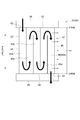
- FIG. 5 is a schematic cross-sectional view of a stationary blade 24 which is a turbine blade 40 according to an embodiment. 4 and 5, illustration of a part of the configuration of the turbine blade 40 is omitted.
- the arrows in the figure indicate the flow direction of the cooling medium.
- a turbine blade 40 that is a moving blade 26 includes a blade portion 42, a platform 80, and a blade root portion 82.
- the blade root 82 is embedded in the rotor 8 (see FIG. 1), and the moving blades 26 rotate with the rotor 8.
- the platform 80 is integrally configured with the wing root 82.
- the wing portion 42 is provided to extend along the radial direction of the rotor 8 (hereinafter, sometimes simply referred to as “radial direction”), and the proximal end 50 fixed to the platform 80 and the radial direction And a distal end 48 opposite to the proximal end 50.
- turbine blade 40 may be stationary blade 24. As shown in FIG. 5, the turbine blade 40, which is the stator blade 24, is positioned radially outward with respect to the blade 42, the inner shroud 86 positioned radially inward with respect to the blade 42, and the blade 42. And an outer shroud 88. The outer shroud 88 is supported by the turbine casing 22, and the vanes 24 are supported by the turbine casing 22 via the outer shroud 88.
- the wing portion 42 has an outer end 52 located on the outer shroud 88 side (i.e., radially outer side) and an inner end 54 located on the inner shroud 86 side (i.e., radially inner side).
- the blade 42 of the turbine blade 40 extends from the base end 50 to the tip 48 in the case of the moving blade 26 (see FIGS. 2 to 4) and the outer end 52 in the case of the stationary blade 24.
- the wing surface of the wing portion 42 is in the wing height direction between the base end 50 and the tip end 48 in the case of the moving blade 26 and between the outer end 52 and the inner end 54 in the case of the stator blade 24. It is formed by a pressure surface (abdominal surface) 56 extending along and a suction surface (back surface) 58 (see FIG. 3).
- the cooling passage 66 is a flow passage for flowing a cooling medium (for example, air or the like) for cooling the turbine blade 40.
- the cooling passage 66 forms part of a serpentine flow passage 60 provided inside the wing 42.
- the serpentine flow path 60 shown in FIGS. 2 to 5 includes a plurality of paths 60a to 60e extending along the wing height direction, and arranged in this order from the front edge 44 side to the rear edge 46 side. There is. Adjacent ones of the plurality of paths 60a to 60e (for example, the path 60a and the path 60b) are connected to each other on the tip 48 side or the base end 50 side, and the direction of the coolant flow is wing height at this connection It is like a return flow channel which is reversed in the longitudinal direction, and has a serpentine flow channel 60 as a whole in a meandering shape.
- the cooling passage 66 is the final pass 60 e of the serpentine flow passage 60.
- the final pass 60e is provided on the most downstream trailing edge 46 side in the coolant flow direction among the plurality of passes 60a to 60e constituting the serpentine flow passage 60.
- the cooling medium is, for example, an internal flow passage 84 formed inside the blade root 82 and an inlet opening 62 provided on the proximal end 50 side of the blade 42 (FIGS. 4) and is introduced into the serpentine channel 60, and flows sequentially through the plurality of paths 60a to 60e.
- the cooling medium flowing in the final path 60e on the most downstream side in the flow direction of the cooling medium among the plurality of paths 60a to 60e passes through the outlet opening 64 provided on the tip 48 side of the wing portion 42 It flows out to the outside combustion gas channel 28.
- the cooling medium is, for example, an internal flow passage (not shown) formed inside the outer shroud 88 and an inlet opening 62 provided on the outer end 52 side of the wing 42 (see FIG. 5) and is introduced into the serpentine channel 60, and flows sequentially through the plurality of paths 60a to 60e.
- the cooling medium flowing through the final path 60e furthest downstream in the flow direction of the cooling medium among the plurality of paths 60a to 60e is an outlet opening 64 provided on the inner end 54 side (inner shroud 86 side) of the wing portion 42. It flows out to the combustion gas channel 28 outside the turbine blade 40 via the.
- a portion of the compressed air compressed by the compressor 2 may be led to the cooling passage 66.
- the compressed air from the compressor 2 may be supplied to the cooling passage 66 after being cooled by heat exchange with a cold heat source.
- the shape of the serpentine flow path 60 is not limited to the shape shown by FIG.2 and FIG.3.
- a plurality of serpentine flow paths may be formed inside the wing portion 42 of one turbine blade 40.
- the serpentine flow channel 60 may branch into a plurality of flow channels at a branch point on the serpentine flow channel 60.
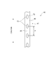
- a plurality of cooling holes 70 are formed in the rear edge 47 (portion including the rear edge 46) of the wing portion 42 so as to be arranged along the wing height direction.
- the plurality of cooling holes 70 communicate with the cooling passage 66 (the final path 60 e of the serpentine flow passage 60 in the illustrated example) formed inside the wing 42 and the wing at the rear edge 47 of the wing 42 It is open to the surface of 42.
- a portion of the cooling medium flowing through the cooling passage 66 passes through the cooling holes 70 and flows out of the opening of the trailing edge 47 of the wing portion 42 to the combustion gas flow path 28 outside the turbine blade 40.
- the passage of the cooling medium through the cooling holes 70 in this manner causes the trailing edge 47 of the wing 42 to be convectively cooled.
- the surface of the trailing edge 47 of the wing 42 may be the surface including the trailing edge 46 of the wing 42 or may be the surface of the wing near the trailing edge 46, the trailing edge end face It may be 49 surfaces.
- the surface of the wing 42 at the trailing edge 47 of the wing 42 is the trailing edge 46 side of the wing 42 including the trailing edge 46 in the cord direction (see FIG. 3) connecting the leading edge 44 and the trailing edge 46 It may be the surface of the wing 42 in a portion of 10%.
- the pressure surface (abdominal side) 56 and the negative pressure surface (back side) intersect at the end of the rear edge 46 on the axially downstream side of the rotor 8, and the end surface facing the axially downstream side of the rotor 8 Say.
- the plurality of cooling holes 70 have an uneven distribution of the opening density which is not constant in the wing height direction.
- the distribution of the opening density of the plurality of cooling holes 70 according to some embodiments will be described.
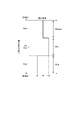
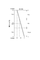
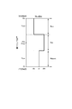
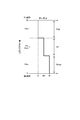
- 6 to 8 and FIGS. 14 and 15 are graphs showing an example of the distribution of the opening density in the blade height direction of the trailing edge 47 of the moving blade 26 (the turbine blade 40) in one embodiment.
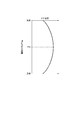
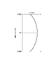
- FIGS. 9 and 13 are graphs showing an example of the temperature distribution of the combustion gas in the wing height direction.
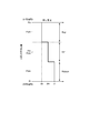
- 10 to 12 are graphs showing an example of the distribution of the opening density in the blade height direction of the trailing edge 47 of the stationary blade 24 (the turbine blade 40) according to one embodiment.
- FIG. 16 is a cross-sectional view taken along the blade height direction at the trailing edge 47 of the turbine blade 40 according to one embodiment
- FIG. 17 is a diagram illustrating the trailing edge 47 of the turbine blade 40 according to one embodiment. It is the figure seen in the direction which goes to the front edge from the rear edge of a part.
- upstream and downstream mean “upstream of the coolant flow in the cooling passage 66" and “upstream of the coolant flow in the cooling passage 66", respectively. .
- the index indicating the opening density of the cooling holes 70 in the central region including the middle position Pm between the first end and the second end, which are both ends of the wing 42 in the wing height direction (hereinafter referred to as opening density index (Also referred to as d_mid)
- the opening density index d_up of the cooling holes 70 in the upstream area located upstream of the central area and the opening density index of the cooling holes 70 in the downstream area located downstream of the central area Rm d_down satisfies the relationship of d_up ⁇ d_mid ⁇ d_down.
- the aperture density index d_down satisfies the relationship d_up ⁇ d_down ⁇ d_mid.
- the cooling medium flows in the cooling passage 66 (final pass 60e of the serpentine passage 60) from the proximal end 50 side to the distal end 48 side (see FIGS. 2 and 4)
- the “upstream side” and “downstream side” of the coolant flow in the cooling passage 66 correspond to the proximal end 50 side and the distal end 48 side of the wing portion 42 in the cooling passage 66, respectively.
- the first end and the second end, which are both ends of the wing 42 in the wing height direction, correspond to the tip 48 and the base 50, respectively.
- the opening of the cooling hole 70 in the central region Rm including the intermediate position Pm between the tip 48 and the proximal end 50 of the wing 42 in the wing height direction.
- the opening density index d_down of the cooling hole 70 in the downstream region Rdown satisfies the relationship of d_up ⁇ d_mid ⁇ d_down.
- the wing height direction area of the wing portion 42 includes the central area Rm and the upstream area Rup including the proximal end 50 and located closer to the proximal end 50 than the central area Rm; It is divided into three regions including 48 and a downstream region Rdown located closer to the tip 48 than the central region Rm.
- the opening density of the cooling holes 70 is uniform and constant in each of the three regions, and the opening density changes in a step-like manner in the blade height direction.
- the opening density index d_mid of the cooling holes 70 in the central region Rm is constant at the opening density index dm at the intermediate position Pm, and the opening density index d_up of the cooling holes 70 in the upstream region Rup is more based on the intermediate position Pm.
- the opening density index dr (where dr ⁇ dm) is constant at the position Pr on the end 50 side, and the opening density index d_down of the cooling hole 70 in the downstream region Rdown is the opening at the position Pt on the tip 48 side than the intermediate position Pm. It is constant at the density index dt (where dm ⁇ dt).
- the opening density of all the cooling holes 70 in each region is made constant the same.
- the opening density indices of the cooling holes 70 at the positions may be d_up and d_mid and d_down, respectively, and the relationship of d_up ⁇ d_mid ⁇ d_down may be satisfied.
- the area intermediate position in each area is represented by Pdm, Pcm, Pum for each of the upstream area Rup, the central area Rm, and the downstream area Rdown.
- Pdm, Pcm and Pum are radial lengths between the position of the radially outermost cooling hole 70 and the position of the radially innermost cooling hole 70 in each region. It may be an intermediate position of Further, the positions of the cooling holes may be located at positions corresponding to the middle of the number of cooling holes arranged in the radial direction of the cooling holes in each region. Further, the hole diameter D of the cooling hole 70 may be the same hole diameter D from the tip 48 side to the base end 50 side, or may be a combination of cooling holes 70 with different hole diameters D.
- the average opening density index in each region is d_up ⁇ d_mid ⁇ d_down.
- the relationship between Here, the average opening density index in each area means an index indicating the average value of the opening density of all the cooling holes 70 in each area.
- the area intermediate position Pum of the upstream area Rup includes the position from the base end 50 to 1 ⁇ 4 L with respect to the total length L between the tip 48 and the base end 50 in the wing height direction, and the base end It is desirable to arrange at a position close to the 50 side. It is desirable that the area intermediate position Pcm of the central area Rm be disposed between the position of a length of 1 ⁇ 4 L from the proximal end 50 to the position of a length of 3 ⁇ 4 L. In addition, it is desirable that the region intermediate position Pdm of the downstream region Rdown includes a position of a length of 3 ⁇ 4 L from the proximal end 50 and be disposed at a position between the distal end 48 and the distal end 48.
- the opening density of the cooling holes 70 continuously changes in the wing height direction of the wing portion 42 so as to increase from the base end 50 side to the tip end 48 side.
- the opening density index d_mid of the cooling hole 70 in the central region Rm is a value in a range including the opening density index dm at the intermediate position Pm
- the opening density index d_up of the cooling hole 70 in the upstream region Rup is the proximal end 50.
- the opening density index d_down of the cooling hole 70 in the downstream region Rdown is a value not less than the opening density index dr at the position Pr on the side and less than the opening density index dm at the middle position Pm. It is a value smaller than dt and larger than the aperture density index dm at the intermediate position Pm.
- the cooling medium flows while cooling the wing portion 42, so the temperature is higher toward the downstream side (tip 48 side) of the cooling medium flow
- the cooling passage 66 formed inside the wing portion 42 of the moving blade 26 (the turbine blade 40)
- the cooling medium flows while cooling the wing portion 42, so the temperature is higher toward the downstream side (tip 48 side) of the cooling medium flow
- the opening density of the cooling holes 70 is made smaller than that in the other regions, so that the opening density of the cooling holes 70 as the whole wing portion 42 is relatively reduced. be able to.
- the pressure in the cooling passage 66 can be easily maintained high, so that the differential pressure between the cooling passage 66 and the pressure outside the turbine blade 40 (for example, the combustion gas passage 28 of the gas turbine 1) can be maintained appropriately.
- the cooling medium can be easily supplied to the cooling holes 70 effectively.
- the distribution of the opening density of the cooling holes 70 in the blade height direction may be such that the above-mentioned opening density indexes d_mid, d_up and d_down satisfy the relationship of d_up ⁇ d_mid ⁇ d_down, and the graph of FIG. 6 or FIG. It is not limited to what is shown in.
- the region in the blade height direction of the wing portion 42 is divided into more than three regions, and the opening density of the cooling holes 70 in each region gradually increases from the base end 50 toward the tip 48 Thus, it may be changed stepwise.
- the opening density of the cooling holes 70 changes continuously in a partial region, and the opening density of the cooling holes 70 is constant in another partial region. It may be
- the opening density index d_mid of the cooling hole 70 in the central region and cooling in the upstream region located on the upstream side (proximal 50 side) of the central region satisfy the relationship of d_up ⁇ d_down ⁇ d_mid.
- the wing height direction region of the wing portion 42 includes the central region Rm, the upstream region Rup including the proximal end 50 and located closer to the proximal end 50 than the central region Rm, and the tip It is divided into three regions including 48 and a downstream region Rdown located closer to the tip 48 than the central region Rm.
- the opening density of the cooling holes 70 is constant in each of the three regions, and the opening density changes stepwise in the blade height direction.
- the opening density index d_mid of the cooling holes 70 in the central region Rm is constant at dm at the intermediate position Pm, and the opening density index d_up of the cooling holes 70 in the upstream region Rup is closer to the proximal end 50 than the intermediate position Pm.
- the opening density index dr (where dr ⁇ dm) at the position Pr of the position is constant, and the opening density index d_down of the cooling hole 70 in the downstream region Rdown is the opening density index dt at the position Pt closer to the tip 48 than the intermediate position Pm. (However, it is constant at dr ⁇ dt ⁇ dm).
- the temperature of the gas flowing through the combustion gas flow path 28 (see FIG. 1) in which the moving blade 26 (the turbine blade 40) is disposed has, for example, a distribution as shown in the graph of FIG.
- the central region including the intermediate position Pm between the distal end 48 and the proximal end 50 tends to be higher than the region on the distal end 48 side of the wing portion 42 and the region on the proximal end 50 side.
- the cooling passage 66 formed inside the wing portion 42 since the cooling medium flows while cooling the wing portion 42, a temperature distribution which becomes higher toward the downstream side (the tip 48 side) of the cooling medium flow occurs There is.
- the flow rate of the cooling medium through the cooling holes 70 in the central region Rm in the blade height direction is maximized, and the above-described downstream region Rdown It is desirable that the flow rate of the cooling medium through the cooling holes 70 be larger than the upstream region Rup in the direction of.
- the cooling medium is heated up in the process of flowing in the final path 60e, and the metal temperature of the cooling holes 70 at the tip 48 or the downstream region Rdown of the final path 60e becomes the highest.
- the opening density distribution of the cooling holes 70 shown in FIG. 20C and FIG. 6 is selected. Damage can be suppressed.
- the heat input received from the combustion gas by the wing portion 42 in the central region Rm is large, and the central region Rm shown in FIG.
- the metal temperature of the cooling hole 70 in the central region Rm may exceed the use limit temperature.
- the supply flow rate of the cooling medium flowing through the cooling holes 70 in the central region Rm can be increased.
- the opening density index of the cooling holes 70 in the upstream region Rup is further reduced, and the metal temperature of the cooling holes 70 in the tip 48 of the final pass 60e and the downstream region Rdown and the metal temperature in the central region Rm An aperture density distribution that fits within the operating limit temperature may be selected.
- the creep strength described above in the central region Rm and the upstream region Rup falls within the creep limit, and the opening density distribution of the cooling holes 70 in each region in the present embodiment may be selected. .
- the opening density index d_mid of the cooling holes 70 in the central region Rm is the opening density of the cooling holes 70 in the upstream region Rup and the downstream region Rdown.
- the opening density index d_down of the cooling hole 70 in the downstream region Rdown is compared to the opening density index d_up of the cooling hole 70 in the upstream region Rup.
- the supply flow rate of the cooling medium via the cooling holes 70 can be increased in the downstream region Rdown where the temperature of the cooling medium is higher than the upstream region Rup.
- the trailing edge 47 of the moving blade 26 (the turbine blade 40) can be properly cooled.
- the opening density of all the cooling holes 70 in each region is made constant, and
- the opening density indices of the cooling holes 70 at the positions may be d_up and d_mid and d_down, respectively, to satisfy the relationship of d_up ⁇ d_down ⁇ d_mid.
- the average opening density index in each region is d_up ⁇ d_down ⁇ d_mid.
- the hole diameter D of the cooling hole 70 may be the same hole diameter D from the tip 48 side to the base end 50 side, or may be a combination of cooling holes 70 with different hole diameters D.
- the distribution of the opening density of the cooling holes 70 in the wing height direction may be such that the above-mentioned opening density indexes d_mid, d_up and d_down satisfy the relationship of d_up ⁇ d_down ⁇ d_mid, as shown in the graph of FIG. It is not limited to.
- the opening density of the cooling holes 70 in each region may be changed stepwise so as to satisfy the above-mentioned relationship. Good.
- the opening density of the cooling holes 70 may be continuously changed in at least a partial region. In this case, the opening density of the cooling holes 70 may be constant in the other part of the wing 42 in the wing height direction.
- the cooling medium flows from the side of the outer end 52 toward the side of the inner end 54 in the cooling passage 66 (final pass 60e of the serpentine passage 60) (see FIG. 5).
- the “upstream side” and “downstream side” of the coolant flow in the passage 66 correspond to the outer end 52 side and the inner end 54 side of the wing 42 in the cooling passage 66, respectively.
- the first end and the second end which are both ends of the wing 42 in the wing height direction correspond to the outer end 52 and the inner end 54, respectively.
- the opening of the cooling hole 70 in the central region including the middle position Pm between the outer end 52 and the inner end 54 of the wing 42 in the wing height direction.
- Density index d_mid Opening density index d_up of cooling hole 70 in the upstream area located on the upstream side (outer end 52 side) than the central area, and downstream located on the downstream side (inner end 54 side) than the central area
- the opening density index d_down of the cooling hole 70 in the side area satisfies the relationship of d_up ⁇ d_mid ⁇ d_down.
- the wing height direction region of the wing portion 42 includes the central region Rm and the upstream region Rup located on the outer end 52 side of the central region Rm including the outer end 52; And a downstream region Rdown that includes the end 54 and is located on the inner end 54 side of the central region Rm, and is divided into three regions.
- the opening density of the cooling holes 70 is constant in each of the three regions, and the opening density changes stepwise in the blade height direction.
- the opening density index d_mid of the cooling holes 70 in the central region Rm is constant at the opening density index dm at the intermediate position Pm, and the opening density index d_up of the cooling holes 70 in the upstream region Rup is outside the intermediate position Pm
- the aperture density index do at a position Po on the end 52 side is constant (where do ⁇ dm)
- the aperture density index d_down of the cooling hole 70 in the downstream region Rdown is a position Pi on the inner end 54 side than the intermediate position Pm.
- the aperture density index di (where dm ⁇ di) is constant.
- the opening density of the cooling holes 70 continuously changes in the wing height direction of the wing portion 42 so as to increase from the outer end 52 side to the inner end 54 side.
- the opening density index d_mid of the cooling hole 70 in the central region Rm is a value in a range including the opening density index dm at the intermediate position Pm
- the opening density index d_up of the cooling hole 70 in the upstream region Rup is the outer end 52
- the opening density index d_down of the cooling hole 70 in the downstream region Rdown is equal to or higher than the opening density index do at the position Po of the side and the opening density index d_down of the cooling hole 70 at the intermediate position Pm It is a value smaller than the index di and larger than the aperture density index dm at the intermediate position Pm.
- the cooling medium flows while cooling the wing portion 42, so the downstream side (inner end 54 side) of the cooling medium flow There may be a temperature distribution at which the temperature is high, that is, the above-described heat-up.
- the position on the downstream side (inner end 54 side) of the cooling passage 66 in the cooling medium flow direction By increasing the opening density of the cooling holes 70 compared to the position of), the flow rate of the cooling medium supplied through the cooling holes 70 on the downstream side (inner end 54 side) where the temperature of the cooling medium becomes relatively high. It can be increased. Thereby, depending on the temperature distribution of the cooling passage 66, the trailing edge 47 of the stationary blade 24 (turbine blade 40) can be properly cooled.
- the opening density of all the cooling holes 70 in each region is made constant, and the intermediate region in the radial direction in each region
- the opening density indices of the cooling holes 70 at the positions may be d_up and d_mid and d_down, respectively, and the relationship of d_up ⁇ d_mid ⁇ d_down may be satisfied.
- the average opening density index in each region is d_up ⁇ d_mid ⁇ d_down.
- the hole diameter D of the cooling hole 70 may be the same hole diameter D from the tip 48 side to the base end 50 side, or may be a combination of cooling holes 70 with different hole diameters D.
- the distribution of the opening density of the cooling holes 70 in the blade height direction may be such that the above-mentioned opening density indexes d_mid, d_up and d_down satisfy the relationship of d_up ⁇ d_mid ⁇ d_down, and the graph of FIG. It is not limited to what is shown in.
- the area in the wing height direction in the wing portion 42 is divided into more than three areas, and the opening density of the cooling holes 70 in each area gradually increases from the inner end 54 side toward the outer end 52 side. It may be changed in a step-like manner.
- the opening density of the cooling holes 70 changes continuously in a partial region, and the opening density of the cooling holes 70 is constant in another partial region. It may be
- the opening density index d_mid of the cooling hole 70 in the central region and the cooling in the upstream region located on the upstream side (outer end 52 side) of the central region satisfy the relationship of d_up ⁇ d_down ⁇ d_mid.
- the wing height direction area of the wing portion 42 includes the central area Rm, the upstream area Rup including the outer end 52 and located closer to the outer end 52 than the central area Rm; And a downstream region Rdown that includes the end 54 and is located on the inner end 54 side of the central region Rm, and is divided into three regions.
- the opening density of the cooling holes 70 is constant in each of the three regions, and the opening density changes stepwise in the blade height direction. That is, the opening density index d_mid of the cooling holes 70 in the central region Rm is constant at dm at the intermediate position Pm, and the opening density index d_up of the cooling holes 70 in the upstream region Rup is closer to the outer end 52 than the intermediate position Pm.
- the opening density index d_down of the cooling hole 70 in the downstream region Rdown is constant at the opening density index do at the position Po of the area and the opening density index at the position Pi closer to the inner end 54 than the intermediate position Pm. It is constant at di (however, do ⁇ di ⁇ dm).
- the temperature of the gas flowing through the combustion gas flow path 28 (see FIG. 1) in which the stator vanes 24 (turbine blades 40) are disposed has a distribution as shown in the graph of FIG.
- the central region including the middle position Pm between the outer end 52 and the inner end 54 tends to be higher than the region at the outer end 52 side and the region at the inner end 54 side of the wing portion 42.
- the cooling passage 66 formed in the inside of the wing portion 42 the cooling medium flows while cooling the wing portion 42, so a temperature distribution which becomes higher toward the downstream side (inner end 54 side) of the cooling medium flow is generated. There is a case.
- the flow rate of the cooling medium through the cooling holes 70 in the central region Rm in the blade height direction is maximized, and the above-described downstream region Rdown It is desirable that the flow rate of the cooling medium through the cooling holes 70 be larger than the upstream region Rup in the direction of.
- the cooling medium is heated up in the process of flowing in the final path 60e, and the metal temperature of the cooling holes 70 in the inner end 54 or the downstream region Rdown of the final path 60e becomes the highest.
- damage to the blade can be suppressed by selecting the opening density distribution of the cooling holes 70 shown in FIG.
- the heat input received from the combustion gas by the wing portion 42 in the central region Rm is large, and the cooling holes in the central region Rm shown in FIG.
- the metal temperature of the cooling hole 70 in the central region Rm may exceed the use limit temperature.
- the opening density index of the cooling holes 70 in the central region Rm is further increased to enhance the cooling. That is, the opening density index of the cooling holes 70 in the downstream region Rdown is made smaller, and the opening density index of the cooling holes 70 in the central region Rm is enlarged, and the supply flow rate of the cooling medium flowing through the cooling holes 70 in the downstream region Rdown is narrowed.
- the supply flow rate of the cooling medium flowing through the cooling holes 70 in the central region Rm can be increased.
- the opening density index of the cooling holes 70 in the upstream region Rup is further reduced, and the metal temperature of the cooling holes 70 in the inner end 54 of the final pass 60e and the downstream region Rdown and the metal temperature in the central region Rm
- the aperture density distribution may be selected such that the temperature falls within the operating limit temperature.
- the opening density index d_mid of the cooling holes 70 in the central region Rm is the opening density of the cooling holes 70 in the upstream region Rup and the downstream region Rdown.
- the opening density index d_down of the cooling hole 70 in the downstream region Rdown is compared to the opening density index d_up of the cooling hole 70 in the upstream region Rup.
- the opening density of all the cooling holes 70 in each region is made constant, and the intermediate region in the radial direction in each region
- the opening density indices of the cooling holes 70 at the positions may be d_up and d_mid and d_down, respectively, to satisfy the relationship of d_up ⁇ d_down ⁇ d_mid.
- the average opening density index in each region is d_up ⁇ d_down ⁇ d_mid.
- the hole diameter D of the cooling hole 70 may be the same hole diameter D from the tip 48 side to the base end 50 side, or may be a combination of cooling holes 70 with different hole diameters D.
- the distribution of the opening density of the cooling holes 70 in the blade height direction may be any as long as the above-mentioned opening density indexes d_mid, d_up and d_down satisfy the relationship of d_up ⁇ d_down ⁇ d_mid, as shown in the graph of FIG. It is not limited to.
- the opening density of the cooling holes 70 in each region may be changed stepwise so as to satisfy the above-mentioned relationship. Good.
- the opening density of the cooling holes 70 may be continuously changed in at least a partial region. In this case, the opening density of the cooling holes 70 may be constant in the other part of the wing 42 in the wing height direction.
- the turbine blade 40 is a moving blade 26 (see FIG. 4).
- the opening density index d_tip at the distal end side located closer to the tip 48 than the central area and the opening density index d_root at the proximal end side located closer to the proximal end 50 than the central area are d_tip ⁇ d_mid ⁇ d_root Meet the relationship.
- the wing height direction area of the wing portion 42 includes a central region Rm, a tip end region Rtip including the tip 48 and positioned closer to the tip 48 than the central region Rm, and a base end 50. And a proximal end region Rroot located closer to the proximal end 50 than the central region Rm, and divided into three regions.
- the opening density of the cooling holes 70 is constant in each of the three regions, and the opening density changes stepwise in the blade height direction.
- the aperture density index d_mid of the cooling holes 70 in the central region Rm is constant at the aperture density index dm at the intermediate position Pm
- the aperture density index d_tip of the cooling holes 70 in the distal end region Rtip is the tip more than the intermediate position Pm.
- the opening density index dt (where dt ⁇ dm) at the position Pt on the 48 side is constant
- the opening density index d_root of the cooling hole 70 in the proximal region Rroot is at the position Pr on the proximal end 50 side than the intermediate position Pm. It is constant at the aperture density index dr (where dm ⁇ dr).
- the tip 48 side of the wing portion 42 is A high pressure may occur in the pressure distribution.
- the opening density of the cooling holes 70 is smaller at the position on the tip 48 side of the wing 42 than in the position on the proximal end 50 side.
- the opening density of all the cooling holes 70 in each region is set to be the same and the region in the radial direction in each region is constant. It is also possible to satisfy the relationship of d_tip ⁇ d_mid ⁇ d_root as d_root and d_mid and d_tip, respectively, as the opening density index of the cooling hole 70 at the intermediate position.
- the region intermediate position in each region is indicated by Prm, Pcm, Ptm for each of the proximal region Rroot, the central region Rm, and the distal region Rtip.
- the average opening density index in each region is d_tip ⁇ d_mid ⁇ It is also possible to satisfy the d_root relationship.
- the concept of the area intermediate position and the average aperture density index in each area is as described above.
- the hole diameter D of the cooling hole 70 may be the same hole diameter D from the tip 48 side to the base end 50 side, or may be a combination of cooling holes 70 with different hole diameters D.
- the distribution of the opening density of the cooling holes 70 in the wing height direction may be such that the above-mentioned opening density indexes d_mid, d_tip and d_root satisfy the relationship of d_tip ⁇ d_mid ⁇ d_root, as shown in the graph of FIG. It is not limited to.
- the opening density of the cooling holes 70 in each region may be changed stepwise so as to satisfy the above-mentioned relationship. Good.
- the opening density of the cooling holes 70 may be continuously changed in at least a partial region. In this case, the opening density of the cooling holes 70 may be constant in the other part of the wing 42 in the wing height direction.
- the opening density index d_mid of the cooling hole 70 in the central region described above and the opening density in the distal region located closer to the tip 48 than the central region satisfy the relationship of d_tip ⁇ d_root ⁇ d_mid.
- the wing height direction region of the wing portion 42 includes the central region Rm, and the distal end region Rtip including the distal end 48 and located closer to the distal end 48 than the central region Rm; And a proximal end region Rroot located closer to the proximal end 50 than the central region Rm, and divided into three regions.
- the opening density of the cooling holes 70 is constant in each of the three regions, and the opening density changes stepwise in the blade height direction.
- the aperture density index d_mid of the cooling holes 70 in the central region Rm is constant at the aperture density index dm at the intermediate position Pm
- the aperture density index d_tip of the cooling holes 70 in the distal end region Rtip is the tip more than the intermediate position Pm.
- the opening density index dt (where dt ⁇ dm) at the position Pt on the 48 side is constant
- the opening density index d_root of the cooling hole 70 in the proximal region Rroot is at the position Pr on the proximal end 50 side than the intermediate position Pm. It is constant at the aperture density index dr (where dt ⁇ dr ⁇ dm).
- the temperature of the gas flowing through the combustion gas flow path 28 (see FIG. 1) in which the moving blade 26 (the turbine blade 40) is disposed has, for example, a distribution as shown in the graph of FIG. It tends to be higher in the central region including the intermediate position Pm between the distal end 48 and the proximal end 50 compared to the region on the distal end 48 side of the wing portion 42 and the region on the proximal end 50 side.
- centrifugal force acts on the cooling medium in the cooling passage 66 formed inside the wing portion 42 of the moving blade 26, so the tip 48 of the wing portion 42 in the cooling passage 66.
- a pressure distribution becomes higher toward the side.
- the flow rate of the cooling medium through the cooling hole 70 in the central region in the blade height direction is maximized, and the tip 48 in the blade height direction is It is desirable to reduce the variation in the flow rate of the cooling medium supplied through the cooling holes in the area located on the side and the area located on the proximal end 50 side.
- the opening density index d_mid of the cooling hole 70 in the central region Rm corresponds to the cooling hole in the above-described tip side region Rtip and the base end side region Rroot.
- the opening density index d_tip of the cooling hole 70 in the tip end region Rtip is compared with the opening density index d_root of the cooling hole 70 in the proximal end region Rroot.
- the area of the radial direction in each area is assumed to be the same and the opening density of all the cooling holes 70 in each area is the same for each area of the proximal area Rroot, the central area Rm and the distal area Rtip.
- the opening density indices of the cooling holes 70 at the intermediate position may be d_root and d_mid and d_tip, respectively, to satisfy the relationship of d_tip ⁇ d_root ⁇ d_mid.
- the region intermediate position in each region is indicated by Prm, Pcm, Ptm for each of the proximal region Rroot, the central region Rm, and the distal region Rtip.
- the average opening density index in each region is d_tip ⁇ d_root ⁇
- the relationship of d_mid may be satisfied.
- the concept of the area intermediate position and the average aperture density index in each area is as described above.
- the hole diameter D of the cooling hole 70 may be the same hole diameter D from the tip 48 side to the base end 50 side, or may be a combination of cooling holes 70 with different hole diameters D.
- the distribution of the opening density of the cooling holes 70 in the wing height direction may be such that the above-mentioned opening density indexes d_mid, d_tip and d_root satisfy the relationship of d_tip ⁇ d_root ⁇ d_mid, as shown in the graph of FIG. It is not limited to.
- the opening density of the cooling holes 70 in each region may be changed stepwise so as to satisfy the above-mentioned relationship. Good.
- the opening density of the cooling holes 70 may be continuously changed in at least a partial region. In this case, the opening density of the cooling holes 70 may be constant in the other part of the wing 42 in the wing height direction.
- the respective regions in the wing height direction of the wing portion 42 (the central region Rm, the upstream region Rup Since the opening density of the cooling holes 70 in the downstream region Rdown or in the distal region Rtip and the proximal region Rroot) is constant, processing of the cooling holes in each region is facilitated.
- the ratio of the pitch P of the cooling holes 70 in the blade height direction (see FIG. 16) to the diameter D of the cooling holes 70 (see FIG. 16) P / D may be adopted.
- the diameter D of the cooling holes 70 the maximum diameter, the minimum diameter or the average diameter of the cooling holes 70 may be used.
- the wetted edge length S at the opening end 72 (see FIG. 17) to the surface of the wing portion 42 of the cooling hole 70 that is, the circumferential length of the opening end 72 at the surface of the wing portion 42
- the ratio S / P to the pitch P (see FIG. 17) of the cooling holes 70 in the wing height direction may be employed.
- the number of cooling holes 70 per unit area (or unit length) of the surface of the wing 42 at the trailing edge 47 of the wing 42 may be employed as the above-mentioned opening density index.
- the cooling holes 70 formed in the trailing edge 47 of the blade 42 of the turbine blade 40 may have the following features.
- the cooling holes 70 may be formed to be inclined with respect to a plane orthogonal to the wing height direction.
- the cooling holes 70 are formed to be inclined with respect to the plane orthogonal to the wing height direction, thereby forming the cooling holes 70 in parallel to the plane perpendicular to the wing height direction.
- the cooling holes 70 can be made longer. Thereby, the trailing edge of the turbine blade 40 can be cooled effectively.
- the angle A (see FIG. 16) between the extending direction of the cooling holes 70 and the plane orthogonal to the wing height direction is 15 ° or more and 45 ° or less, or 20 ° or more and 40 Or less. If the angle A is in the above range, a relatively long cooling hole 70 is formed while maintaining the ease of processing the cooling hole 70 or maintaining the strength of the trailing edge 47 of the wing 42. can do.
- the cooling holes 70 may be formed parallel to one another.
- the cooling holes 70 may be formed parallel to one another.
- more cooling holes 70 are formed in the trailing edge 47 of the wing portion 42 than in the case where the plurality of cooling holes 70 are not parallel with each other. can do. Thereby, the trailing edge 47 of the turbine blade 40 can be cooled effectively.
- a turbulator 90 is provided on the inner surface of the serpentine flow passage 60 in order to facilitate heat transfer with the cooling medium.
- FIG. 18 the arrangement of the cooling holes 70 formed in the vicinity of the trailing edge 47, and the configuration of the final pass 60e of the cooling passage 66 arranged on the upstream side in the flow direction of the cooling medium adjacent to the trailing edge 47. It is shown.
- a turbulator 90 as a turbulence promoting material is disposed from the base end 50 to the tip 48 and on each inner wall surface 68 of the pressure surface (vent side) 56 and suction surface (back side) 58 of the wing portion 42. ing. Similarly, a turbulator (not shown) is disposed also in the serpentine flow passage 60 upstream of the final pass 60 e in the flow direction of the cooling medium.
- the turbulators 90 disposed in the serpentine flow passage 60 are provided on the inner wall surface 68 of the pressure side (vent side) 56 and the suction side (back side) 58 of at least one of the paths 60a to 60e. It is provided, and is formed in height e on the basis of the inner wall surface 68 of the turbulator 90.
- the passage width in the back and forth direction of each of the paths 60a to 60e is H, and in each flow passage, a plurality of turbulators 90 arranged adjacent to each other in the radial direction are provided at intervals of pitch PP.
- the turbulator 90 has a ratio of the pitch PP to the height e of the turbulator 90 (PP / e) and the ratio of the height e of the turbulator 90 to the passage width H in the dorso-ventral direction (e / H) and the flow direction of the cooling medium.
- the inclination angle of the turbulator 90 is formed so as to be substantially constant from the proximal end 50 to the distal end 48, and is arranged so as to obtain an optimum heat transfer with the cooling medium.
- the passage width H of the final pass 60e is narrower than the other passes 60a to 60d other than the final pass 60e. Therefore, when it is difficult to select the turbulator height e corresponding to the appropriate ratio (e / H) of the height e of the turbulator 90 of the cooling passage 66 and the passage width H to obtain the appropriate heat transfer described above There is. That is, in the case of the final pass 60e, in order to maintain an appropriate ratio (e / H) between the height e of the turbulator 90 and the passage width H as compared with the other passes 60a to 60d, the height of the turbulator 90 If the value e becomes too small, processing of the turbulator 90 may be difficult. In particular, since the passage width H is narrower at the distal end 48 side than at the proximal end 50 side, selection of the appropriate height e of the turbulator 90 may be more difficult.
- the cooling medium flowing into the final pass 60e of the serpentine flow passage 60 is heated from the inner wall surface 68 of the wing portion 42 in the process of flowing down the respective passes 60a to 60d upstream of the final pass 60e, and supplied to the final pass 60e. Be done. Therefore, the metal temperature of the final pass 60e is likely to be high, and in particular the vicinity of the tip 48 side of the final pass 60e is likely to be high. Therefore, a means is employed such that the metal temperature of the final pass 60e does not exceed the use limit temperature.
- the passage cross-sectional area of the final pass 60e is decreased toward the outlet opening 64 to increase the flow rate of the cooling medium, promote heat transfer with the final pass 60e, and reduce the metal temperature of the final pass 60e to the use limit temperature or less. It becomes possible to suppress.
- the passage width H in the vicinity of the tip 48 of the final pass 60e is in the direction in which it is further narrowed.
- the turbulator 90 whose height e is relatively large with respect to the appropriate height e of the turbulator 90 with respect to the passage width H is selected. is there. That is, the height e of the turbulator 90 formed in the final pass 60e is smaller than that of the turbulators 90 of the other passes 60a to 60d other than the final pass 60e, but the height e of the turbulator 90 is from the base end 50 to the tip 48 There is a case where a constant same height e is selected without changing.
- the ratio (e / H) of the height e of the turbulator 90 to the passage width H in the final pass 60e is the ratio of the height e to the passage width H applied to the other passes 60a to 60d (e / H) H) be bigger.
- the turbulator 90 whose height e is relatively larger than the appropriate value in the final pass 60e the occurrence of turbulent flow of the cooling medium in the final pass 60e is promoted, and the other passes 60a to 60d and In comparison, heat transfer between the final pass 60 e and the cooling medium is further promoted.
- the metal temperature of the final pass 60e is suppressed to the use limit temperature or less.
- the final pass 60 e is achieved by decreasing the passage width H in the final pass 60 e toward the tip 48 or by making the height e of the turbulator 90 of the final pass 60 e relatively larger than the other passes 60 a to 60 d. Cooling is enhanced and the occurrence of thermal stress etc. is improved.
- the opening of the cooling hole 70 of the trailing edge 47 from the intermediate position in the blade height direction of the final pass 60e to the outlet opening 64 of the tip 48 The density is increased to absorb the temperature rise of the inflowing cooling medium, and the rise of the metal temperature of the trailing edge 47 is suppressed to enable the proper cooling of the trailing edge 47 including the final pass 60e.
- a representation representing a relative or absolute arrangement such as “in a direction”, “along a direction”, “parallel”, “orthogonal”, “center”, “concentric” or “coaxial”
- a representation representing a relative or absolute arrangement such as “in a direction”, “along a direction”, “parallel”, “orthogonal”, “center”, “concentric” or “coaxial”
- expressions that indicate that things such as “identical”, “equal” and “homogeneous” are equal states not only represent strictly equal states, but also have tolerances or differences with which the same function can be obtained. It also represents the existing state.
- expressions representing shapes such as a square shape and a cylindrical shape not only indicate shapes such as a square shape and a cylindrical shape in a geometrically strict sense, but also within the range where the same effect can be obtained. Also, the shape including the uneven portion, the chamfered portion, and the like shall be indicated. Moreover, in the present specification, the expressions “comprising”, “including” or “having” one component are not exclusive expressions excluding the presence of other components.
Landscapes
- Engineering & Computer Science (AREA)
- Mechanical Engineering (AREA)
- General Engineering & Computer Science (AREA)
- Chemical & Material Sciences (AREA)
- Combustion & Propulsion (AREA)
- Physics & Mathematics (AREA)
- Fluid Mechanics (AREA)
- Turbine Rotor Nozzle Sealing (AREA)
Abstract
Description
しかしながら、特許文献1には、冷却通路内における温度分布及び/又は圧力分布に応じたタービン翼の冷却を行うことについて、具体的に開示されていない。
翼部と、
前記翼部の内部において翼高さ方向に沿って延在する冷却通路と、
前記翼高さ方向に沿って配列するように前記翼部の後縁部に形成され、前記冷却通路に連通するとともに前記後縁部における前記翼部の表面に開口する複数の冷却孔と、
を備え、
前記後縁部における前記複数の冷却孔の形成領域は、
前記翼高さ方向における前記翼部の第1端と第2端との中間位置を含み、且つ、複数の前記冷却孔の開口密度を示す指標がd_midで一定である中央領域と、
前記翼高さ方向において前記中央領域よりも前記冷却通路内における冷却媒体流れの上流側に位置し、且つ、複数の前記冷却孔の開口密度を示す指標がd_upで一定である上流側領域と、
前記翼高さ方向において前記中央領域よりも前記冷却媒体流れの下流側に位置し、且つ、複数の前記冷却孔の開口密度を示す指標がd_downで一定である下流側領域と、を含み、d_up<d_mid<d_downの関係を満たす。
翼部と、
前記翼部の内部において翼高さ方向に沿って延在する冷却通路と、
前記翼高さ方向に沿って配列して前記翼部の後縁部を対流冷却するように前記後縁部に形成され、前記冷却通路に連通するとともに前記後縁部を貫通して後縁端面に開口する複数の冷却孔と、を備え、
前記翼高さ方向における前記翼部の第1端と第2端との中間位置を含む中央領域における前記冷却孔の開口密度を示す指標をd_midとし、
前記翼高さ方向において前記中央領域よりも前記冷却通路内における冷却媒体流れの上流側に位置する領域における前記指標をd_upとし、
前記翼高さ方向において前記中央領域よりも前記冷却媒体流れの下流側に位置する領域における前記指標をd_downとしたとき、d_up<d_down<d_midの関係を満たすとともに、
前記後縁部における前記複数の冷却孔の形成領域は、
前記翼高さ方向における前記翼部の第1端と第2端との中間位置を含み、且つ、複数の前記冷却孔の開口密度を示す指標がd_midで一定である中央領域と、
前記翼高さ方向において前記中央領域よりも前記冷却通路内における冷却媒体流れの上流側であって前記形成領域における前記冷却媒体流れの最上流側に位置し、且つ、複数の前記冷却孔の開口密度を示す指標がd_upで一定である最上流側領域と、
前記翼高さ方向において前記中央領域よりも前記冷却媒体流れの下流側であって前記形成領域における前記冷却媒体流れの最下流側に位置し、且つ、複数の前記冷却孔の開口密度を示す指標がd_downで一定である最下流側領域と、を含む。
この点、上記(2)の構成によれば、中央領域における冷却孔の開口密度を、該中央領域よりも上流側に位置する領域(上流側領域)及び下流側に位置する領域(下流側領域)における冷却孔の開口密度よりも大きくしたので、燃焼ガス流路を流通するガス温度が相対的に高くなる中央領域において、冷却孔を介した冷却媒体の供給流量を増やすことができる。また、上記(2)の構成では、上述の下流側領域において、上述の上流側領域に比べて冷却孔の開口密度を大きくしたので、冷却媒体温度が上流側領域よりも高くなる下流側領域において、冷却孔を介した冷却媒体の供給流量を増やすことができる。こうして、冷却通路の温度分布に応じて、タービン翼の後縁部を適切に冷却することができる。
翼部と、
前記翼部の内部において翼高さ方向に沿って延在する冷却通路と、
前記翼高さ方向に沿って配列するように前記翼部の後縁部に形成され、前記冷却通路に連通するとともに前記後縁部における前記翼部の表面に開口する複数の冷却孔と、
を備えるタービン翼であって、
前記タービン翼は動翼であり、
前記翼高さ方向における前記翼部の先端と基端との中間位置を含む中央領域における前記冷却孔の開口密度を示す指標をd_midとし、前記翼高さ方向において前記中央領域よりも前記先端側に位置する領域における前記指標をd_tipとし、
前記翼高さ方向において前記中央領域よりも前記基端側に位置する領域における前記指標をd_rootとしたとき、d_tip<d_mid<d_rootの関係を満たすとともに、
前記開口密度を示す指標d_tip、d_mid及びd_rootは、前記後縁部を貫通するように設けられる前記冷却孔の貫通孔径Dの、前記翼高さ方向に隣り合う前記冷却孔間のピッチPに対する比D/Pであり、
前記後縁部における前記複数の冷却孔の形成領域は、
前記翼高さ方向における前記翼部の先端と基端との中間位置を含み、且つ、複数の前記冷却孔の開口密度を示す指標がd_midで一定である中央領域と、
前記翼高さ方向において前記中央領域よりも前記先端側であって前記形成領域のうち最も前記先端寄りに位置し、且つ、複数の前記冷却孔の開口密度を示す指標がd_tipで一定である先端側領域と、
前記翼高さ方向において前記中央領域よりも前記基端側であって前記形成領域のうち最も前記基端寄りに位置し、且つ、複数の前記冷却孔の開口密度を示す指標がd_rootで一定である基端側領域と、を含む。
翼部と、
前記翼部の内部において翼高さ方向に沿って延在する冷却通路と、
前記翼高さ方向に沿って配列して前記翼部の後縁部を対流冷却するように前記後縁部に形成され、前記冷却通路に連通するとともに前記後縁部を貫通して後縁端面に開口する複数の冷却孔と、
を備えるタービン翼であって、
前記タービン翼は動翼であり、
前記翼高さ方向における前記翼部の先端と基端との中間位置を含む中央領域における前記冷却孔の開口密度を示す指標をd_midとし、前記翼高さ方向において前記中央領域よりも前記先端側に位置する領域における前記指標をd_tipとし、前記翼高さ方向において前記中央領域よりも前記基端側に位置する領域における前記指標をd_rootとしたとき、d_tip<d_root<d_midの関係を満たし、
前記後縁部における前記複数の冷却孔の形成領域は、
前記翼高さ方向における前記翼部の先端と基端との中間位置を含み、且つ、複数の前記冷却孔の開口密度を示す指標がd_midで一定である中央領域と、
前記翼高さ方向において前記中央領域よりも前記先端側であって前記形成領域のうち最も前記先端寄りに位置し、且つ、複数の前記冷却孔の開口密度を示す指標がd_tipで一定である先端側領域と、
前記翼高さ方向において前記中央領域よりも前記基端側であって前記形成領域のうち最も前記基端寄りに位置し、且つ、複数の前記冷却孔の開口密度を示す指標がd_rootで一定である基端側領域と、
を含む。
この点、上記(4)の構成によれば、中央領域における冷却孔の開口密度を、該中央領域よりも先端側に位置する領域(先端側領域)及び基端側に位置する領域(基端側領域)における冷却孔の開口密度よりも大きくしたので、燃焼ガス流路を流通するガス温度が相対的に高くなる中央領域において、冷却孔を介した冷却媒体の供給流量を増やすことができる。また、上記(4)の構成では、上述の先端側領域において、上述の基端側領域に比べて冷却孔の開口密度を小さくしたので、上述の圧力分布がある場合であっても、先端側領域と基端側領域とで冷却孔を介した冷却媒体の供給流量のばらつきを小さくすることができる。こうして、冷却通路の圧力分布に応じて、タービン翼の後縁部を適切に冷却することができる。
前記中央領域は、同一径の複数の冷却孔を含み、
前記中央領域より前記翼部の先端側に位置する先端側領域及び前記中央領域より前記翼部の基端側に位置する基端側領域は、前記中央領域における冷却孔と同一径の複数の冷却孔を含む。
前記タービン翼は動翼であり、
前記翼部の先端側に、前記冷却通路の出口開口が形成されている。
前記タービン翼は静翼であり、
前記翼部の内側シュラウド側に、前記冷却通路の出口開口が形成されている。
上記(1)乃至(11)の何れかに記載のタービン翼と、
前記タービン翼が設けられる燃焼ガス流路を流れる燃焼ガスを生成するための燃焼器と、を備える。
ガスターピンの動翼26は、高速回転するロータ8に固定され(図1参照)、高温の燃焼ガス雰囲気中で稼働するため、冷却媒体を用いて翼部42を冷却している。図20Aに示すように、動翼26の翼部42の内部には冷却通路66が形成され、基端50側から供給された冷却媒体は、冷却通路66内を流れて翼部42を冷却し、後縁46側の最終パス60eの先端48から燃焼ガス中に排出される。また、冷却媒体は、最終パス60eを流れ、後縁部47のロータ8の軸方向下流側に形成され後縁46に開口を有する複数の冷却孔70に供給される。冷却媒体は、冷却孔70を流れ燃焼ガス中に排出する過程で、後縁部47を対流冷却している。また、特許文献1に開示された冷却孔は、図20Bに示すように、後縁部47の翼高さ方向の全長に渡って、同一孔径の冷却孔70を同一のピッチで配置して、冷却孔70の開口密度を翼高さ方向に均一としている。この例が、従来の冷却孔の配置の一例である。
圧縮機2には、空気取入口12から取り込まれた空気が送られるようになっており、この空気は、複数の静翼16及び複数の動翼18を通過して圧縮されることで高温高圧の圧縮空気となる。
静翼24はタービン車室22側に固定されており、ロータ8の周方向に沿って配列される複数の静翼24が静翼列を構成している。また、動翼26はロータ8に植設されており、ロータ8の周方向に沿って配列される複数の動翼26が動翼列を構成している。静翼列と動翼列とは、ロータ8の軸方向において交互に配列されている。
タービン6では、燃焼ガス流路28に流れ込んだ燃焼器4からの燃焼ガスが複数の静翼24及び複数の動翼26を通過することでロータ8が回転駆動され、これにより、ロータ8に連結された発電機が駆動されて電力が生成されるようになっている。タービン6を駆動した後の燃焼ガスは、排気室30を介して外部へ排出される。
図5に示すように、静翼24であるタービン翼40は、翼部42と、翼部42に対して径方向内側に位置する内側シュラウド86と、翼部42に対して径方向外側に位置する外側シュラウド88と、を備えている。外側シュラウド88はタービン車室22に支持され、静翼24は外側シュラウド88を介してタービン車室22に支持される。翼部42は、外側シュラウド88側(すなわち径方向外側)に位置する外側端52と、内側シュラウド86側(すなわち径方向内側)に位置する内側端54と、を有する。
図2~図5に示すサーペンタイン流路60は、それぞれ翼高さ方向に沿って延在する複数のパス60a~60eを含み、前縁44側から後縁46側に向かってこの順に配列されている。これらの複数のパス60a~60eのうち互いに隣り合うパス(例えばパス60aとパス60b)は、先端48側又は基端50側において互いに接続され、この接続部において、冷却媒体流れの方向が翼高さ方向において逆向きに折り返るリターン流路のようになっており、サーペンタイン流路60全体として蛇行した形状を有している。
以下、幾つかの実施形態に係る複数の冷却孔70の開口密度の分布について説明する。
図6~図8、図14及び図15は、それぞれ、一実施形態における動翼26(タービン翼40)の後縁部47の翼高さ方向における開口密度の分布の一例を示すグラフである。図9及び図13は、それぞれ、翼高さ方向における燃焼ガスの温度分布の一例を示すグラフである。図10~図12は、それぞれ、一実施形態における静翼24(タービン翼40)の後縁部47の翼高さ方向における開口密度の分布の一例を示すグラフである。図16は、一実施形態に係るタービン翼40の後縁部47における翼高さ方向に沿った断面図であり、図17は、一実施形態に係るタービン翼40の後縁部47を、翼部の後縁から前縁に向かう方向に視た図である。
タービン翼40が動翼26である場合、冷却媒体は、冷却通路66(サーペンタイン流路60の最終パス60e)を基端50側から先端48側に向かって流れるので(図2及び図4参照)、冷却通路66内における冷却媒体流れの「上流側」及び「下流側」は、それぞれ、冷却通路66における翼部42の基端50側及び先端48側に相当する。また、翼高さ方向における翼部42の両端である第1端及び第2端は、それぞれ先端48及び基端50に相当する。
すなわち、中央領域Rmにおける冷却孔70の開口密度指標d_midは、中間位置Pmにおける開口密度指標dmで一定であり、上流側領域Rupにおける冷却孔70の開口密度指標d_upは、中間位置Pmよりも基端50側の位置Prにおける開口密度指標dr(ただしdr<dm)で一定であり、下流側領域Rdownにおける冷却孔70の開口密度指標d_downは、中間位置Pmよりも先端48側の位置Ptにおける開口密度指標dt(ただしdm<dt)で一定である。
すなわち、中央領域Rmにおける冷却孔70の開口密度指標d_midは、中間位置Pmにおける開口密度指標dmを含む範囲の値であり、上流側領域Rupにおける冷却孔70の開口密度指標d_upは、基端50側の位置Prにおける開口密度指標dr以上かつ中間位置Pmにおける開口密度指標dm未満の値であり、下流側領域Rdownにおける冷却孔70の開口密度指標d_downは、先端48側の位置Ptにおける開口密度指標dt以下かつ中間位置Pmにおける開口密度指標dmよりも大きい値である。
例えば、翼部42における翼高さ方向の領域を3つよりも多い領域に分割し、各領域における冷却孔70の開口密度が、基端50側から先端48側に向かうにしたがい徐々に大きくなるように、ステップ状に変化するようにしてもよい。
また、例えば、翼部42における翼高さ方向の領域において、一部の領域では冷却孔70の開口密度が連続的に変化するとともに、他の一部の領域では冷却孔70の開口密度が一定であってもよい。
すなわち、中央領域Rmにおける冷却孔70の開口密度指標d_midは、中間位置Pmにおけるdmで一定であり、上流側領域Rupにおける冷却孔70の開口密度指標d_upは、中間位置Pmよりも基端50側の位置Prにおける開口密度指標dr(ただしdr<dm)で一定であり、下流側領域Rdownにおける冷却孔70の開口密度指標d_downは、中間位置Pmよりも先端48側の位置Ptにおける開口密度指標dt(ただしdr<dt<dm)で一定である。
一方、翼部42の内部に形成された冷却通路66内では、冷却媒体は翼部42を冷却しながら流れるため、冷却媒体流れの下流側(先端48側)ほど高温となる温度分布が生じる場合がある。このような場合には、後縁部47を適切に冷却するためには、翼高さ方向の中央領域Rmにおける冷却孔70を介した冷却媒体流量を最大とし、且つ、上述の下流側領域Rdownの方において上流側領域Rupよりも冷却孔70を介した冷却媒体流量が大きくなるようにすることが望ましい。
例えば、翼部42における翼高さ方向の領域を3つよりも多い領域に分割し、各領域における冷却孔70の開口密度が上述の関係を満たすように、ステップ状に変化するようにしてもよい。
また、例えば、翼部42における翼高さ方向の領域において、少なくとも一部の領域において冷却孔70の開口密度が連続的に変化していてもよい。この場合、翼部42の翼高さ方向における他の一部の領域において冷却孔70の開口密度が一定であってもよい。
タービン翼40が静翼24である場合、冷却媒体は、冷却通路66(サーペンタイン流路60の最終パス60e)を外側端52側から内側端54側に向かって流れるので(図5参照)、冷却通路66内における冷却媒体流れの「上流側」及び「下流側」は、それぞれ、冷却通路66内における翼部42の外側端52側及び内側端54側に相当する。また、翼高さ方向における翼部42の両端である第1端及び第2端は、それぞれ外側端52及び内側端54に相当する。
すなわち、中央領域Rmにおける冷却孔70の開口密度指標d_midは、中間位置Pmにおける開口密度指標dmで一定であり、上流側領域Rupにおける冷却孔70の開口密度指標d_upは、中間位置Pmよりも外側端52側の位置Poにおける開口密度指標do(ただしdo<dm)で一定であり、下流側領域Rdownにおける冷却孔70の開口密度指標d_downは、中間位置Pmよりも内側端54側の位置Piにおける開口密度指標di(ただしdm<di)で一定である。
すなわち、中央領域Rmにおける冷却孔70の開口密度指標d_midは、中間位置Pmにおける開口密度指標dmを含む範囲の値であり、上流側領域Rupにおける冷却孔70の開口密度指標d_upは、外側端52側の位置Poにおける開口密度指標do以上かつ中間位置Pmにおける開口密度指標dm未満の値であり、下流側領域Rdownにおける冷却孔70の開口密度指標d_downは、内側端54側の位置Piにおける開口密度指標di以下かつ中間位置Pmにおける開口密度指標dmよりも大きい値である。
例えば、翼部42における翼高さ方向の領域を3つよりも多い領域に分割し、各領域における冷却孔70の開口密度が、内側端54側から外側端52側に向かうにしたがい徐々に大きくなるように、ステップ状に変化するようにしてもよい。
また、例えば、翼部42における翼高さ方向の領域において、一部の領域では冷却孔70の開口密度が連続的に変化するとともに、他の一部の領域では冷却孔70の開口密度が一定であってもよい。
すなわち、中央領域Rmにおける冷却孔70の開口密度指標d_midは、中間位置Pmにおけるdmで一定であり、上流側領域Rupにおける冷却孔70の開口密度指標d_upは、中間位置Pmよりも外側端52側の位置Poにおける開口密度指標do(ただしdo<dm)で一定であり、下流側領域Rdownにおける冷却孔70の開口密度指標d_downは、中間位置Pmよりも内側端54側の位置Piにおける開口密度指標di(ただしdo<di<dm)で一定である。
一方、翼部42の内部に形成された冷却通路66内では、冷却媒体は翼部42を冷却しながら流れるため、冷却媒体流れの下流側(内側端54側)ほど高温となる温度分布が生じる場合がある。このような場合には、後縁部47を適切に冷却するためには、翼高さ方向の中央領域Rmにおける冷却孔70を介した冷却媒体流量を最大とし、且つ、上述の下流側領域Rdownの方において上流側領域Rupよりも冷却孔70を介した冷却媒体流量が大きくなるようにすることが望ましい。
例えば、翼部42における翼高さ方向の領域を3つよりも多い領域に分割し、各領域における冷却孔70の開口密度が上述の関係を満たすように、ステップ状に変化するようにしてもよい。
また、例えば、翼部42における翼高さ方向の領域において、少なくとも一部の領域において冷却孔70の開口密度が連続的に変化していてもよい。この場合、翼部42の翼高さ方向における他の一部の領域において冷却孔70の開口密度が一定であってもよい。
すなわち、中央領域Rmにおける冷却孔70の開口密度指標d_midは、中間位置Pmにおける開口密度指標dmで一定であり、先端側領域Rtipにおける冷却孔70の開口密度指標d_tipは、中間位置Pmよりも先端48側の位置Ptにおける開口密度指標dt(ただしdt<dm)で一定であり、基端側領域Rrootにおける冷却孔70の開口密度指標d_rootは、中間位置Pmよりも基端50側の位置Prにおける開口密度指標dr(ただしdm<dr)で一定である。
例えば、翼部42における翼高さ方向の領域を3つよりも多い領域に分割し、各領域における冷却孔70の開口密度が上述の関係を満たすように、ステップ状に変化するようにしてもよい。
また、例えば、翼部42における翼高さ方向の領域において、少なくとも一部の領域において冷却孔70の開口密度が連続的に変化していてもよい。この場合、翼部42の翼高さ方向における他の一部の領域において冷却孔70の開口密度が一定であってもよい。
すなわち、中央領域Rmにおける冷却孔70の開口密度指標d_midは、中間位置Pmにおける開口密度指標dmで一定であり、先端側領域Rtipにおける冷却孔70の開口密度指標d_tipは、中間位置Pmよりも先端48側の位置Ptにおける開口密度指標dt(ただしdt<dm)で一定であり、基端側領域Rrootにおける冷却孔70の開口密度指標d_rootは、中間位置Pmよりも基端50側の位置Prにおける開口密度指標dr(ただしdt<dr<dm)で一定である。
一方、ガスタービン1の運転時、動翼26の翼部42の内部に形成された冷却通路66内の冷却媒体には遠心力が作用するため、該冷却通路66内において翼部42の先端48側ほど高圧となる圧力分布が生じる場合がある。このような場合には、後縁部47を適切に冷却するためには、翼高さ方向の中央領域における冷却孔70を介した冷却媒体流量を最大とし、且つ、翼高さ方向における先端48側に位置する領域と基端50側に位置する領域とで、冷却孔を介した冷却媒体の供給流量のばらつきを小さくすることが望ましい。
例えば、翼部42における翼高さ方向の領域を3つよりも多い領域に分割し、各領域における冷却孔70の開口密度が上述の関係を満たすように、ステップ状に変化するようにしてもよい。
また、例えば、翼部42における翼高さ方向の領域において、少なくとも一部の領域において冷却孔70の開口密度が連続的に変化していてもよい。この場合、翼部42の翼高さ方向における他の一部の領域において冷却孔70の開口密度が一定であってもよい。
あるいは、上述の開口密度指標として、冷却孔70の翼部42の表面への開口端72(図17参照)における濡れ縁長さS(即ち、翼部42表面における開口端72の周長)と、翼高さ方向における冷却孔70のピッチP(図17参照)との比S/Pを採用してもよい。
あるいは、上述の開口密度指標として、翼部42の後縁部47における翼部42の表面の単位面積あたり(又は単位長さあたり)の冷却孔70の個数を採用してもよい。
このように、冷却孔70が、翼高さ方向に直行する平面に対して傾きをもって形成されることにより、該冷却孔70を翼高さ方向に直交する平面と平行に形成する場合に比べて、冷却孔70を長くすることができる。これにより、タービン翼40の後縁部を効果的に冷却することができる。
このように、複数の冷却孔70が互いに平行に形成されることにより、複数の冷却孔70が互いに平行でない場合に比べて、より多くの冷却孔70を翼部42の後縁部47に形成することができる。これにより、タービン翼40の後縁部47を効果的に冷却することができる。
例えば、「同一」、「等しい」及び「均質」等の物事が等しい状態であることを表す表現は、厳密に等しい状態を表すのみならず、公差、若しくは、同じ機能が得られる程度の差が存在している状態も表すものとする。
また、本明細書において、四角形状や円筒形状等の形状を表す表現は、幾何学的に厳密な意味での四角形状や円筒形状等の形状を表すのみならず、同じ効果が得られる範囲で、凹凸部や面取り部等を含む形状も表すものとする。
また、本明細書において、一の構成要素を「備える」、「含む」、又は、「有する」という表現は、他の構成要素の存在を除外する排他的な表現ではない。
2 圧縮機
4 燃焼器
6 タービン
8 ロータ
10 圧縮機車室
12 空気取入口
16 静翼
18 動翼
20 ケーシング
22 タービン車室
24 静翼
26 動翼
28 燃焼ガス流路
30 排気室
40 タービン翼
42 翼部
44 前縁
46 後縁
47 後縁部
48 先端
49 後縁端面
50 基端
52 外側端
54 内側端
56 圧力面
58 負圧面
60 サーペンタイン流路
60a~60e パス
60e 最終パス
62 入口開口
64 出口開口
66 冷却通路
68 内壁面
70 冷却孔
72 開口端
80 プラットフォーム
82 翼根部
84 内部流路
86 内側シュラウド
88 外側シュラウド
90 タービュレータ
Pm 中間位置
Pcm 中央領域中間位置
Pum 上流側領域中間位置
Pdm 下流側領域中間位置
Ptm 先端側領域中間位置
Prm 基端側領域中間位置
Rtip 先端側領域
Rm 中央領域
Rroot 基端側領域
Rup 上流側領域
Rdown 下流側領域
Claims (12)
- 翼部と、
前記翼部の内部において翼高さ方向に沿って延在する冷却通路と、
前記翼高さ方向に沿って配列するように前記翼部の後縁部に形成され、前記冷却通路に連通するとともに前記後縁部における前記翼部の表面に開口する複数の冷却孔と、
を備え、
前記後縁部における前記複数の冷却孔の形成領域は、
前記翼高さ方向における前記翼部の第1端と第2端との中間位置を含み、且つ、複数の前記冷却孔の開口密度を示す指標がd_midで一定である中央領域と、
前記翼高さ方向において前記中央領域よりも前記冷却通路内における冷却媒体流れの上流側に位置し、且つ、複数の前記冷却孔の開口密度を示す指標がd_upで一定である上流側領域と、
前記翼高さ方向において前記中央領域よりも前記冷却媒体流れの下流側に位置し、且つ、複数の前記冷却孔の開口密度を示す指標がd_downで一定である下流側領域と、を含み、
d_up<d_mid<d_downの関係を満たすタービン翼。 - 翼部と、
前記翼部の内部において翼高さ方向に沿って延在する冷却通路と、
前記翼高さ方向に沿って配列して前記翼部の後縁部を対流冷却するように前記後縁部に形成され、前記冷却通路に連通するとともに前記後縁部を貫通して後縁端面に開口する複数の冷却孔と、
を備え、
前記翼高さ方向における前記翼部の第1端と第2端との中間位置を含む中央領域における前記冷却孔の開口密度を示す指標をd_midとし、
前記翼高さ方向において前記中央領域よりも前記冷却通路内における冷却媒体流れの上流側に位置する領域における前記指標をd_upとし、
前記翼高さ方向において前記中央領域よりも前記冷却媒体流れの下流側に位置する領域における前記指標をd_downとしたとき、
d_up<d_down<d_midの関係を満たすとともに
前記後縁部における前記複数の冷却孔の形成領域は、
前記翼高さ方向における前記翼部の第1端と第2端との中間位置を含み、且つ、複数の前記冷却孔の開口密度を示す指標がd_midで一定である中央領域と、
前記翼高さ方向において前記中央領域よりも前記冷却通路内における冷却媒体流れの上流側であって前記形成領域における前記冷却媒体流れの最上流側に位置し、且つ、複数の前記冷却孔の開口密度を示す指標がd_upで一定である最上流側領域と、
前記翼高さ方向において前記中央領域よりも前記冷却媒体流れの下流側であって前記形成領域における前記冷却媒体流れの最下流側に位置し、且つ、複数の前記冷却孔の開口密度を示す指標がd_downで一定である最下流側領域と、を含むタービン翼。 - 翼部と、
前記翼部の内部において翼高さ方向に沿って延在する冷却通路と、
前記翼高さ方向に沿って配列するように前記翼部の後縁部に形成され、前記冷却通路に連通するとともに前記後縁部における前記翼部の表面に開口する複数の冷却孔と、
を備えるタービン翼であって、
前記タービン翼は動翼であり、
前記翼高さ方向における前記翼部の先端と基端との中間位置を含む中央領域における前記冷却孔の開口密度を示す指標をd_midとし、前記翼高さ方向において前記中央領域よりも前記先端側に位置する領域における前記指標をd_tipとし、前記翼高さ方向において前記中央領域よりも前記基端側に位置する領域における前記指標をd_rootとしたとき、
d_tip<d_mid<d_rootの関係を満たすとともに、
前記開口密度を示す指標d_tip、d_mid及びd_rootは、前記後縁部を貫通するように設けられる前記冷却孔の貫通孔径Dの、前記翼高さ方向に隣り合う前記冷却孔間のピッチPに対する比D/Pであり、
前記後縁部における前記複数の冷却孔の形成領域は、
前記翼高さ方向における前記翼部の先端と基端との中間位置を含み、且つ、複数の前記冷却孔の開口密度を示す指標がd_midで一定である中央領域と、
前記翼高さ方向において前記中央領域よりも前記先端側であって前記形成領域のうち最も前記先端寄りに位置し、且つ、複数の前記冷却孔の開口密度を示す指標がd_tipで一定である先端側領域と、
前記翼高さ方向において前記中央領域よりも前記基端側であって前記形成領域のうち最も前記基端寄りに位置し、且つ、複数の前記冷却孔の開口密度を示す指標がd_rootで一定である基端側領域と、
を含むタービン翼。 - 翼部と、
前記翼部の内部において翼高さ方向に沿って延在する冷却通路と、
前記翼高さ方向に沿って配列して前記翼部の後縁部を対流冷却するように前記後縁部に形成され、前記冷却通路に連通するとともに前記後縁部を貫通して後縁端面に開口する複数の冷却孔と、
を備えるタービン翼であって、
前記タービン翼は動翼であり、
前記翼高さ方向における前記翼部の先端と基端との中間位置を含む中央領域における前記冷却孔の開口密度を示す指標をd_midとし、前記翼高さ方向において前記中央領域よりも前記先端側に位置する領域における前記指標をd_tipとし、前記翼高さ方向において前記中央領域よりも前記基端側に位置する領域における前記指標をd_rootとしたとき、
d_tip<d_root<d_midの関係を満たし、
前記後縁部における前記複数の冷却孔の形成領域は、
前記翼高さ方向における前記翼部の先端と基端との中間位置を含み、且つ、複数の前記冷却孔の開口密度を示す指標がd_midで一定である中央領域と、
前記翼高さ方向において前記中央領域よりも前記先端側であって前記形成領域のうち最も前記先端寄りに位置し、且つ、複数の前記冷却孔の開口密度を示す指標がd_tipで一定である先端側領域と、
前記翼高さ方向において前記中央領域よりも前記基端側であって前記形成領域のうち最も前記基端寄りに位置し、且つ、複数の前記冷却孔の開口密度を示す指標がd_rootで一定である基端側領域と、
を含むタービン翼。 - 前記中央領域は、同一径の複数の冷却孔を含み、
前記中央領域より前記翼部の先端側に位置する先端側領域及び前記中央領域より前記翼部の基端側に位置する基端側領域は、前記中央領域における冷却孔と同一径の複数の冷却孔を含む、
請求項1乃至4の何れか一項に記載のタービン翼。 - 前記翼部の前記表面が前記後縁部の端面である請求項1乃至5の何れか一項に記載のタービン翼。
- 前記複数の冷却孔は、前記翼高さ方向に直交する平面に対して傾きをもって形成された請求項1乃至6の何れか一項に記載のタービン翼。
- 前記複数の冷却孔は、互いに平行に形成された請求項1乃至7の何れか一項に記載のタービン翼。
- 前記冷却通路は、前記翼部の内部に形成されたサーペンタイン流路のうちの最終パスである請求項1乃至8の何れか一項に記載のタービン翼。
- 前記タービン翼は動翼であり、
前記翼部の先端側に、前記冷却通路の出口開口が形成されている
請求項1乃至9の何れか一項に記載のタービン翼。 - 前記タービン翼は静翼であり、
前記翼部の内側シュラウド側に、前記冷却通路の出口開口が形成されている
請求項1又は2に記載のタービン翼。 - 請求項1乃至11の何れか一項に記載のタービン翼と、
前記タービン翼が設けられる燃焼ガス流路を流れる燃焼ガスを生成するための燃焼器と、を備えるガスタービン。
Priority Applications (5)
| Application Number | Priority Date | Filing Date | Title |
|---|---|---|---|
| DE112018002830.5T DE112018002830B4 (de) | 2017-07-07 | 2018-07-04 | Turbinenschaufel und gasturbine |
| CN201880036090.6A CN110691892B (zh) | 2017-07-07 | 2018-07-04 | 涡轮叶片及燃气涡轮 |
| US16/617,266 US11339669B2 (en) | 2017-07-07 | 2018-07-04 | Turbine blade and gas turbine |
| KR1020197034910A KR102364543B1 (ko) | 2017-07-07 | 2018-07-04 | 터빈 블레이드 및 가스 터빈 |
| MX2019014789A MX2019014789A (es) | 2017-07-07 | 2018-07-04 | Pala de turbina y turbina de gas. |
Applications Claiming Priority (2)
| Application Number | Priority Date | Filing Date | Title |
|---|---|---|---|
| JP2017134101A JP6345319B1 (ja) | 2017-07-07 | 2017-07-07 | タービン翼及びガスタービン |
| JP2017-134101 | 2017-07-07 |
Publications (1)
| Publication Number | Publication Date |
|---|---|
| WO2019009331A1 true WO2019009331A1 (ja) | 2019-01-10 |
Family
ID=62635680
Family Applications (1)
| Application Number | Title | Priority Date | Filing Date |
|---|---|---|---|
| PCT/JP2018/025385 Ceased WO2019009331A1 (ja) | 2017-07-07 | 2018-07-04 | タービン翼及びガスタービン |
Country Status (8)
| Country | Link |
|---|---|
| US (1) | US11339669B2 (ja) |
| JP (1) | JP6345319B1 (ja) |
| KR (1) | KR102364543B1 (ja) |
| CN (1) | CN110691892B (ja) |
| DE (1) | DE112018002830B4 (ja) |
| MX (1) | MX2019014789A (ja) |
| TW (1) | TWI691643B (ja) |
| WO (1) | WO2019009331A1 (ja) |
Families Citing this family (8)
| Publication number | Priority date | Publication date | Assignee | Title |
|---|---|---|---|---|
| KR102321824B1 (ko) * | 2020-04-28 | 2021-11-04 | 두산중공업 주식회사 | 터빈 베인, 그리고 이를 포함하는 터빈 |
| CN113586165B (zh) * | 2021-07-20 | 2022-09-16 | 西安交通大学 | 一种具有单一煤油冷却通道的涡轮叶片 |
| CN114776400B (zh) | 2022-04-11 | 2024-02-20 | 北京航空航天大学 | 一种航空发动机涡轮机匣及导叶一体化冷却系统 |
| JP7847031B2 (ja) * | 2022-05-06 | 2026-04-16 | 三菱重工業株式会社 | タービン翼及びガスタービン |
| JP7770258B2 (ja) * | 2022-06-15 | 2025-11-14 | 三菱重工業株式会社 | 動翼、及びこれを備えているガスタービン |
| JP7778043B2 (ja) * | 2022-06-30 | 2025-12-01 | 三菱重工業株式会社 | 静翼、及びこれを備えているガスタービン |
| US12650079B2 (en) | 2022-08-24 | 2026-06-09 | General Electric Company | Turbine engine airfoil |
| US11952912B2 (en) * | 2022-08-24 | 2024-04-09 | General Electric Company | Turbine engine airfoil |
Citations (4)
| Publication number | Priority date | Publication date | Assignee | Title |
|---|---|---|---|---|
| US20070031252A1 (en) * | 2005-08-02 | 2007-02-08 | Rolls-Royce Plc | Component comprising a multiplicity of cooling passages |
| US20080273988A1 (en) * | 2006-02-24 | 2008-11-06 | Ian Tibbott | Aerofoils |
| US8807943B1 (en) * | 2010-02-15 | 2014-08-19 | Florida Turbine Technologies, Inc. | Turbine blade with trailing edge cooling circuit |
| US9447692B1 (en) * | 2012-11-28 | 2016-09-20 | S&J Design Llc | Turbine rotor blade with tip cooling |
Family Cites Families (15)
| Publication number | Priority date | Publication date | Assignee | Title |
|---|---|---|---|---|
| JPS4951907U (ja) * | 1972-08-15 | 1974-05-08 | ||
| JPS4951907A (ja) | 1972-09-16 | 1974-05-20 | ||
| FR2476207A1 (fr) * | 1980-02-19 | 1981-08-21 | Snecma | Perfectionnement aux aubes de turbines refroidies |
| JP3142850B2 (ja) * | 1989-03-13 | 2001-03-07 | 株式会社東芝 | タービンの冷却翼および複合発電プラント |
| US5378108A (en) | 1994-03-25 | 1995-01-03 | United Technologies Corporation | Cooled turbine blade |
| US5498126A (en) * | 1994-04-28 | 1996-03-12 | United Technologies Corporation | Airfoil with dual source cooling |
| JPH0814001A (ja) * | 1994-06-29 | 1996-01-16 | Toshiba Corp | ガスタービン翼 |
| JP3817205B2 (ja) | 2002-07-31 | 2006-09-06 | アンリツ株式会社 | ネットワーク中継装置及び該装置の通信離脱方法 |
| JP2004137958A (ja) * | 2002-10-17 | 2004-05-13 | Mitsubishi Heavy Ind Ltd | ガスタービン動翼 |
| US6942449B2 (en) | 2003-01-13 | 2005-09-13 | United Technologies Corporation | Trailing edge cooling |
| US6988872B2 (en) | 2003-01-27 | 2006-01-24 | Mitsubishi Heavy Industries, Ltd. | Turbine moving blade and gas turbine |
| US7165940B2 (en) | 2004-06-10 | 2007-01-23 | General Electric Company | Method and apparatus for cooling gas turbine rotor blades |
| GB0523469D0 (en) * | 2005-11-18 | 2005-12-28 | Rolls Royce Plc | Blades for gas turbine engines |
| US7387492B2 (en) * | 2005-12-20 | 2008-06-17 | General Electric Company | Methods and apparatus for cooling turbine blade trailing edges |
| US9638046B2 (en) * | 2014-06-12 | 2017-05-02 | Pratt & Whitney Canada Corp. | Airfoil with variable land width at trailing edge |
-
2017
- 2017-07-07 JP JP2017134101A patent/JP6345319B1/ja active Active
-
2018
- 2018-07-04 WO PCT/JP2018/025385 patent/WO2019009331A1/ja not_active Ceased
- 2018-07-04 US US16/617,266 patent/US11339669B2/en active Active
- 2018-07-04 MX MX2019014789A patent/MX2019014789A/es unknown
- 2018-07-04 KR KR1020197034910A patent/KR102364543B1/ko active Active
- 2018-07-04 DE DE112018002830.5T patent/DE112018002830B4/de active Active
- 2018-07-04 CN CN201880036090.6A patent/CN110691892B/zh active Active
- 2018-07-05 TW TW107123279A patent/TWI691643B/zh active
Patent Citations (4)
| Publication number | Priority date | Publication date | Assignee | Title |
|---|---|---|---|---|
| US20070031252A1 (en) * | 2005-08-02 | 2007-02-08 | Rolls-Royce Plc | Component comprising a multiplicity of cooling passages |
| US20080273988A1 (en) * | 2006-02-24 | 2008-11-06 | Ian Tibbott | Aerofoils |
| US8807943B1 (en) * | 2010-02-15 | 2014-08-19 | Florida Turbine Technologies, Inc. | Turbine blade with trailing edge cooling circuit |
| US9447692B1 (en) * | 2012-11-28 | 2016-09-20 | S&J Design Llc | Turbine rotor blade with tip cooling |
Also Published As
| Publication number | Publication date |
|---|---|
| DE112018002830T5 (de) | 2020-02-20 |
| KR20190138879A (ko) | 2019-12-16 |
| CN110691892B (zh) | 2022-08-23 |
| CN110691892A (zh) | 2020-01-14 |
| MX2019014789A (es) | 2020-02-10 |
| US20210123349A1 (en) | 2021-04-29 |
| TWI691643B (zh) | 2020-04-21 |
| US11339669B2 (en) | 2022-05-24 |
| JP6345319B1 (ja) | 2018-06-20 |
| TW201920829A (zh) | 2019-06-01 |
| KR102364543B1 (ko) | 2022-02-17 |
| DE112018002830B4 (de) | 2025-12-11 |
| JP2019015252A (ja) | 2019-01-31 |
Similar Documents
| Publication | Publication Date | Title |
|---|---|---|
| JP6345319B1 (ja) | タービン翼及びガスタービン | |
| CN100575672C (zh) | 燃气轮机的透平叶片、燃气轮机的应用及其冷却方法 | |
| EP1630352B1 (en) | Turbine component | |
| CN102834588A (zh) | 用于涡轮机的轮叶或叶片 | |
| CN107366555A (zh) | 叶片以及涡轮转子叶片 | |
| TWI710696B (zh) | 渦輪葉片及燃氣渦輪機 | |
| US20250369358A1 (en) | Rotor blade and gas turbine provided with same | |
| CN110185499A (zh) | 具有排出孔用以递送流体至压力侧边界层膜的涡轮转子叶片 | |
| JP2019183805A5 (ja) | ||
| JPS59231102A (ja) | ガスタ−ビンの翼 | |
| JP6996947B2 (ja) | タービン翼及びガスタービン | |
| JP2021071085A (ja) | タービン翼及びこれを備えたガスタービン | |
| EP3875735A1 (en) | Aerofoil for a gas turbine | |
| JP7674511B2 (ja) | タービン静翼 | |
| US12281594B2 (en) | Turbine blade and gas turbine | |
| JP2019085973A5 (ja) | ||
| JP7847031B2 (ja) | タービン翼及びガスタービン | |
| JPWO2023095721A5 (ja) | ||
| JP2026023829A (ja) | タービン動翼、及びガスタービン | |
| WO2023223741A1 (ja) | タービン翼及びガスタービン |
Legal Events
| Date | Code | Title | Description |
|---|---|---|---|
| 121 | Ep: the epo has been informed by wipo that ep was designated in this application |
Ref document number: 18828560 Country of ref document: EP Kind code of ref document: A1 |
|
| ENP | Entry into the national phase |
Ref document number: 20197034910 Country of ref document: KR Kind code of ref document: A |
|
| WWE | Wipo information: entry into national phase |
Ref document number: 112018002830 Country of ref document: DE |
|
| 122 | Ep: pct application non-entry in european phase |
Ref document number: 18828560 Country of ref document: EP Kind code of ref document: A1 |
|
| WWG | Wipo information: grant in national office |
Ref document number: 112018002830 Country of ref document: DE |