WO2019008725A1 - 天然ガス液化装置用モジュール、天然ガス液化装置、及び天然ガス液化装置の製造方法 - Google Patents
天然ガス液化装置用モジュール、天然ガス液化装置、及び天然ガス液化装置の製造方法 Download PDFInfo
- Publication number
- WO2019008725A1 WO2019008725A1 PCT/JP2017/024814 JP2017024814W WO2019008725A1 WO 2019008725 A1 WO2019008725 A1 WO 2019008725A1 JP 2017024814 W JP2017024814 W JP 2017024814W WO 2019008725 A1 WO2019008725 A1 WO 2019008725A1
- Authority
- WO
- WIPO (PCT)
- Prior art keywords
- natural gas
- frame
- module
- building
- liquefier
- Prior art date
- Legal status (The legal status is an assumption and is not a legal conclusion. Google has not performed a legal analysis and makes no representation as to the accuracy of the status listed.)
- Ceased
Links
Images


Classifications
-
- F—MECHANICAL ENGINEERING; LIGHTING; HEATING; WEAPONS; BLASTING
- F25—REFRIGERATION OR COOLING; COMBINED HEATING AND REFRIGERATION SYSTEMS; HEAT PUMP SYSTEMS; MANUFACTURE OR STORAGE OF ICE; LIQUEFACTION SOLIDIFICATION OF GASES
- F25J—LIQUEFACTION, SOLIDIFICATION OR SEPARATION OF GASES OR GASEOUS OR LIQUEFIED GASEOUS MIXTURES BY PRESSURE AND COLD TREATMENT OR BY BRINGING THEM INTO THE SUPERCRITICAL STATE
- F25J1/00—Processes or apparatus for liquefying or solidifying gases or gaseous mixtures
- F25J1/02—Processes or apparatus for liquefying or solidifying gases or gaseous mixtures requiring the use of refrigeration, e.g. of helium or hydrogen ; Details and kind of the refrigeration system used; Integration with other units or processes; Controlling aspects of the process
- F25J1/0243—Start-up or control of the process; Details of the apparatus used; Details of the refrigerant compression system used
- F25J1/0257—Construction and layout of liquefaction equipments, e.g. valves, machines
- F25J1/0259—Modularity and arrangement of parts of the liquefaction unit and in particular of the cold box, e.g. pre-fabrication, assembling and erection, dimensions, horizontal layout "plot"
-
- E—FIXED CONSTRUCTIONS
- E04—BUILDING
- E04H—BUILDINGS OR LIKE STRUCTURES FOR PARTICULAR PURPOSES; SWIMMING OR SPLASH BATHS OR POOLS; MASTS; FENCING; TENTS OR CANOPIES, IN GENERAL
- E04H5/00—Buildings or groups of buildings for industrial or agricultural purposes
- E04H5/02—Buildings or groups of buildings for industrial purposes, e.g. for power-plants or factories
-
- F—MECHANICAL ENGINEERING; LIGHTING; HEATING; WEAPONS; BLASTING
- F25—REFRIGERATION OR COOLING; COMBINED HEATING AND REFRIGERATION SYSTEMS; HEAT PUMP SYSTEMS; MANUFACTURE OR STORAGE OF ICE; LIQUEFACTION SOLIDIFICATION OF GASES
- F25J—LIQUEFACTION, SOLIDIFICATION OR SEPARATION OF GASES OR GASEOUS OR LIQUEFIED GASEOUS MIXTURES BY PRESSURE AND COLD TREATMENT OR BY BRINGING THEM INTO THE SUPERCRITICAL STATE
- F25J1/00—Processes or apparatus for liquefying or solidifying gases or gaseous mixtures
- F25J1/0002—Processes or apparatus for liquefying or solidifying gases or gaseous mixtures characterised by the fluid to be liquefied
- F25J1/0022—Hydrocarbons, e.g. natural gas
Definitions
- the present invention relates to a technology for constructing a natural gas liquefaction apparatus for liquefying natural gas.
- the natural gas liquefier is a facility for cooling and liquefying natural gas (NG: Natural Gas) produced in gas wells and the like to produce liquefied natural gas (LNG).
- NG Natural Gas
- LNG liquefied natural gas
- modularization efforts have been made such that a large number of devices constituting the NG liquefier are divided into blocks, and a group of devices of each block is incorporated into a common frame (for example, Patent Document 1) .
- a module for constructing an NG liquefier is referred to as a natural gas liquefier module (module for an NG liquefier).
- the module for the NG liquefier is constructed at another site, transported to the construction site of the NG liquefier, and installed on the site.
- an NG liquefier is constituted by combining a plurality of modules for NG liquefiers.
- NG liquefaction module modules include power transformers that perform voltage conversion, power supply control equipment that controls power supply to each power consumer, and power supply devices such as circuit breakers and disconnectors.
- a equipped substation may be provided.
- the module for the NG liquefaction device in the central control room performing overall control of the whole NG liquefaction device, the flow rate setting value, pressure setting value, temperature setting value, etc.
- Information related to the operation control of the controlled device is output to the controller that performs the operation control of the controlled device, or information such as flow rate, pressure, temperature controlled using the controlled device is directed to the central control room
- An instrument control room (Instrument Control Room) equipped with a control information output device for outputting may also be provided.
- Patent Document 1 does not disclose any technology as to whether it is efficient to construct an NG liquefier module and transport it to a construction site to construct an NG liquefier.
- the present invention has been made under such background, and an object thereof is to provide a module for a natural gas liquefier which is easy to transport and install at a construction site.
- a module for a natural gas liquefier comprises: a frame accommodating a group of devices constituting a part of the natural gas liquefier; A power supply device which is provided separately from the frame and supplies power to the power consuming device included in the device group or included in the device group and performs operation control of the controlled device using a control signal An additional building containing at least one of control information output devices for outputting information related to the operation control to a controller;
- the frame and the parallel building are connected so that the frame and the parallel building can be transported integrally, and the natural gas liquefier module is constructed as a construction of the natural gas liquefier It is characterized by having provided the connecting member removed in order to separate a frame and an additional building in the case of installing in a ground.
- the module for a natural gas liquefier may have the following features.
- B When the module for natural gas equipment is installed at a construction site and the connection member is removed, the connection member is connected to the frame so that the frame and the parallel building are placed at their respective installation positions. Connect the side of the building with the side of the building.
- the parallel building has a blast resistant structure, while the frame does not have a blast resistant structure.
- the natural gas liquefying device of the present invention is characterized in that the plurality of natural gas liquefying device modules described above are respectively installed in a state where the connecting member is removed.
- a frame containing a group of devices constituting a part of the natural gas liquefying device and the frame are separately provided, and the power included in the group of devices Control for outputting information related to the operation control to a power supply device that supplies power to a consumer device or a controller that is included in the device group and performs operation control of a controlled device using a control signal
- An additional building accommodating at least one of the information output devices, and a connecting member for connecting the frame and the additional building so that the structure and the additional building can be transported integrally when the module for a natural gas liquefier is transported.
- Constructing a module for a natural gas liquefier comprising: Transporting the module for a natural gas liquefier from the construction site of the module for a natural gas liquefier to the construction site of the natural gas liquefier, When the module for a natural gas liquefier transported to the construction site is installed in the construction site, the connecting member is removed to separate the frame and the parallel building. .
- the method for producing the natural gas liquefier may have the following features.
- (D) In the step of constructing the module for a natural gas liquefier when the power supply equipment is provided in the adjacent building, the power supply equipment and the power consumption equipment to which the power is supplied are supplied with a feeder line. And connecting the control information output device and the controller to which the information related to the operation control is output through a signal line, when the control information output device is provided in the parallel building. Including.
- the connecting member connects the side of the frame and the side of the parallel building, and when the connecting member is removed in the step of separating the frame and the parallel building, the frame and the parallel building each Be placed in the installation position.
- the step of constructing the module for a natural gas liquefier comprises: a step of constructing the juxtaposed building having a blast resistant structure; and a step of constructing the frame by a steel frame structure having no blast resistant structure; Including.
- the frame accommodating the group of devices constituting a part of the natural gas liquefying apparatus and the parallel building accommodating the power supply device or the control information output device are connected via the connecting member, the natural gas At the time of transportation of the liquefier module, it becomes easy to integrally transport the frame and the additional building.
- the frame and the parallel building are separated by removing the connecting member, so that the design standard is not affected. Design and construction of modules for natural gas liquefiers can be performed under less restrictive conditions.
- each process part contained in a natural gas liquefying device It is a structural example of each process part contained in a natural gas liquefying device. It is a top view which shows the example of a layout of the module for natural gas liquefiers arrange
- FIG. 1 is an example of a schematic configuration of a natural gas (NG) liquefier configured using the module for a natural gas liquefier according to this embodiment.
- the NG liquefaction apparatus includes a gas-liquid separation unit 11 for separating liquid from NG, a mercury removal unit 12 for removing mercury in the NG, and an acid gas removal unit for removing acid gas such as carbon dioxide and hydrogen sulfide from the NG. 13, a water removing unit 14 for removing a small amount of water contained in the NG, a liquefaction processing unit 15 for obtaining LNG by cooling and liquefying the NG from which these impurities have been removed, and storing the liquefied LNG And a tank 17.
- the gas-liquid separation unit 11 separates the liquid condensate at normal temperature contained in NG transported by a pipeline or the like.
- the gas-liquid separation unit 11 is added as needed for the purpose of preventing blockage of a sloped long narrow pipe or drum for separating liquid from NG using difference in specific gravity, and transportation process. It includes equipment groups such as antifreeze liquid regeneration towers and reboilers that perform heating and regeneration of antifreeze liquid, and their incidental facilities.
- the mercury removal unit 12 removes a trace amount of mercury contained in NG after the liquid is separated.
- the mercury removal part 12 is equipped with equipment groups, such as a mercury adsorption tower which filled the mercury removal agent in the adsorption tower, and its incidental equipment.
- the acid gas removal unit 13 removes acid gas such as carbon dioxide and hydrogen sulfide that may solidify in LNG during liquefaction.
- acid gas such as carbon dioxide and hydrogen sulfide that may solidify in LNG during liquefaction.
- Examples of the method for removing the acid gas include a method using a gas absorbing solution containing an amine compound and the like, and a method using a gas separation membrane that allows the acid gas in NG to permeate.
- the acid gas removing unit 13 is an absorption tower for bringing the NG and the gas absorbing liquid into countercurrent contact, a regeneration tower for regenerating the gas absorbing liquid having absorbed the acid gas, and a regeneration tower. It comprises equipment groups such as reboilers for heating the gas absorption liquid in the equipment and accessories attached to these.
- the acid gas removal unit 13 includes a group of devices such as a gas separation unit in which a large number of hollow fiber membranes are accommodated in the main body, and an accessory equipment thereof.
- the water removing unit 14 removes a small amount of water contained in the NG.
- the water removal unit 14 is filled with an adsorbent such as molecular sieve or silica gel, and a plurality of adsorption towers are implemented by alternately switching between the NG water removal operation and the regeneration operation of the adsorbent adsorbed with water;
- the apparatus includes a heater for heating the adsorbent regeneration gas (for example, NG after water removal) supplied to the adsorption tower where the operation is being performed, and a group of equipment such as these incidental facilities.
- the NG after the impurities are removed by the processing units 11 to 14 described above is supplied to the liquefaction processing unit 15 and liquefied.
- the liquefaction processing unit 15 includes a pre-cooling heat exchanger that performs pre-cooling of NG with a pre-cooling refrigerant mainly composed of propane, a scrub column that removes heavy components from the NG after pre-cooling, nitrogen, methane, ethane, propane, etc.
- a cryogenic heat exchanger (MCHE: Main Cryogenic Heat Exchanger) that cools, liquefies, and subcools an NG by a mixed refrigerant containing multiple types of refrigerant materials (MCHE: Main Cryogenic Heat Exchanger), and a precooling refrigerant and a mixed refrigerant vaporized by heat exchange
- MCHE Main Cryogenic Heat Exchanger
- a refrigerant compressor 21 that compresses a gas, and equipment groups such as these incidental facilities are provided.
- FIG. 1 shows an example in which the gas turbine 22 is used as a power source for driving the refrigerant compressor 21, a motor or the like may be used depending on the size of the refrigerant compressor 21 or the like.
- a large number of air-cooled heat exchangers (ACHE: Air) for cooling the fluid handled in the NG liquefier, such as a cooler for cooling the gas absorption liquid and the top liquid regenerated in the regenerator.
- -Cooled Heat Exchanger 41 is provided.
- the liquefaction processing unit 15 includes a de-ethanizer for separating ethane from the liquid (liquid heavy components) separated from the cooled NG, a depropanizer for separating propane from the liquid after ethane separation, and a liquid after propane separation And a debinarizer for separating butane from the mixture and obtaining liquid condensate at room temperature.
- the de-ethanizer, the de-propanizer, and the de-butanizer each include equipment such as a rectification column for rectifying each component, a reboiler for heating the liquid in each rectification column, and incidental equipment thereof.
- the rectification unit 16 corresponds to the heavy matter removing unit in the present embodiment.
- the liquefied natural gas (LNG) which has been liquefied and subcooled in the liquefaction processing unit 15 is fed to the storage tank 16 and stored.
- the LNG stored in the storage tank 16 is transported by an unshown LNG pump and shipped to an LNG tanker or pipeline.
- various heating operations performed by the above-described processing units 11 to 16 and heat supplied to the ground antifreeze heater provided on the bottom surface of the storage tank 17 or the like Equipment such as oil heaters and boilers that heat media (for example, hot oil and steam, etc.) and their ancillary equipment, gas turbine generators and gas engine generators that supply power consumed in the NG liquefier, and ancillary equipment A group is also set up.
- Equipment such as oil heaters and boilers that heat media (for example, hot oil and steam, etc.) and their ancillary equipment, gas turbine generators and gas engine generators that supply power consumed in the NG liquefier, and ancillary equipment A group is also set up.
- FIG. 2 shows an example of the layout of the above-mentioned NG liquefier.
- the NG liquefying apparatus of this example is configured by a plurality of NG liquefying apparatus modules M (hereinafter referred to simply as "in-frame apparatus 6 and ACHE 41, etc.” that constitute each processing unit 11 to 16 are housed in a common frame 30). And a module M (hereinafter also referred to as “module M”).
- the device group constituting the liquefaction processing unit 15 is further divided into a plurality of groups, and a plurality of modules M in which the device groups of the respective groups are accommodated in the frame 30 are provided.
- the processing units 11, 12, 13, 14, 16 are also used for the other processing units 11, 12, 13, 14, 16, other equipment groups (in-frame equipment 6 and ACHE 41) that constitute the oil heater, the boiler, and the like.
- a plurality of modules M are provided, each of which is grouped and the equipment group of each group is accommodated in the frame 30.
- a plurality of modules M on the side of the liquefaction processing unit 15 are arranged in the lateral direction, and modules M related to other processing units 11, 12, 13, 14, 16 are arranged in the lateral direction, An NG liquefier is configured by these two rows of modules M.
- a refrigerant compressor 21 which is an MR compressor or a C3 compressor is disposed on both sides of the row of modules M of the liquefaction processing unit 15.
- the base point side of the Y axis of the coordinate axis shown by the solid line in FIG. 2 is called the near side
- the arrow direction side is called the back side.
- the secondary coordinate axes shown by broken lines in FIGS. 2 to 4 indicate the directions focusing on each module M, and the base point side of the Y 'axis of the secondary coordinate axes is called the rear end side and the arrow direction side is called the front end side.
- the frame 30 constituting each module M is formed to have a substantially rectangular planar shape, and the devices included in the device group of each processing unit 11 to 16 are vertically arranged in multiple layers It is a steel frame structure that can be done.
- the upper surface of the frame 30 is provided with a row in which a plurality of ACHEs 41 are arranged along the Y-axis direction from the front end side to the rear end side. Furthermore, a large number of ACHE groups 4 are arranged by providing a plurality of ACHE 41 rows (for convenience of illustration, three rows are shown in FIG. 2) in the width direction of the frame 30. These ACHEs 41 constitute a part of the device group of each of the processing units 11-16.
- the space under the area where the ACHE group 4 is disposed is a pipe rack in which a large number of pipes 42 through which the fluid transferred between the processing units 11 to 16 flows is disposed. It has become.
- the pipes 42 also constitute a part of the equipment group of the processing units 11 to 16.
- connection piping (not shown) for connecting between stationary equipment such as a tower tank and a heat exchanger, moving equipment such as a pump 6a, each stationary equipment, piping 42 between moving equipments and a pipe rack side Etc.).
- the rated voltage of each power consuming device is used among the devices housed in the frame 30, for the power consuming devices such as the ACHE 41 and the pump 6a that consume power for driving. Power is supplied through the feeder line. Therefore, in the frame 30 accommodating these power consuming devices, a transformer including a transformer for performing voltage conversion, a power supply control facility for controlling power supply to each power consuming device, and a power supplying device such as a circuit breaker or disconnector. A room is added.
- a flow control valve for adjusting the flow rate of the fluid includes various controlled devices such as control valves such as flow control valves that increase or decrease the flow rate of heat medium and refrigerant, and on-off valves that open and close depending on the liquid level in the tower tank.
- control valves such as flow control valves that increase or decrease the flow rate of heat medium and refrigerant, and on-off valves that open and close depending on the liquid level in the tower tank.
- a controller is added to these controlled devices, and the controller outputs a control signal to the controlled device based on the result of detection of the flow rate, pressure, temperature, liquid level, etc. of the fluid by the detection unit.
- a control loop for controlling the operation of the device is constructed.
- a device control room containing a control information output device called an FCS (Field Control Station) or the like may also be juxtaposed to the frame 30 containing the devices related to these control loops.
- the control information output device receives the information related to the operation control of the controlled device, such as the flow rate setting value, the pressure setting value, and the temperature setting value received from the operator, in the central control room that performs overall control of the entire NG liquefier. It outputs to a controller that controls the operation of the control device, and outputs information such as the flow rate, pressure, temperature and liquid level of the fluid detected by the detection unit to the central control room.
- the control information output device and the controller and the detection unit of each controlled device are connected via a signal line. Further, in the following description, the above-mentioned transformer room and equipment control room are also referred to as the parallel building 50.
- the module M is constructed in a factory different from the construction site of the NG liquefier, and the completed module M is transported to the construction site by a carrier ship or transport vehicle and then installed in the construction site Work is carried out.
- the power supply devices in the parallel building 50 and the power consumption devices in the frame 30 are connected via the feed line, and the control information output devices in the parallel building 50 and the objects in the frame 30 are connected.
- the controller and the detection unit of the control device are connected via a signal line.
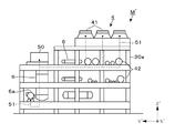
- a module M ′ illustrated in FIG. 4 illustrates an example in which the parallel building 50 which is a transformation room is disposed on the top surface of the tip end side of the frame 30a.
- the power supply device in the parallel building 50 and the power consumption device ACHE 41 and the pump 6 a are connected via a feed line 51 schematically shown by a broken line. If the module M 'of the above configuration is built, the structure 30a and the parallel building 50 are transported integrally, and installed at the construction site, almost no connection work of the feeder line or the signal line occurs. Can be significantly reduced.
- the building 50 that includes equipment (power supply equipment and control information output equipment) that performs important control of the NG liquefier
- equipment power supply equipment and control information output equipment
- the design of a building that can withstand shock is required, and a blast resistant structure may be required for the additional building 50 and the structure that supports it.
- the module M ′ shown in FIG. 4 is configured to easily increase the construction cost.
- the additional building 50 is disposed on the upper surface of the structure 30a, for example, if the additional building 50 is disposed in the space below the pipe 42 on the rear end side of the structure 30a
- the range in which the cross section of the steel frame member of the frame 30a must be increased to support the explosive load can be limited to only the lower layer portion.
- the module M of this example connects the side surface of the frame 30 accommodating the device group (in-frame device 6, ACHE 41, etc.) and the side surface of the parallel building 50 through the connecting member 31. Adopted the configuration.
- the module M of this example arranges the additional building 50 at the side position on the rear end side of the frame 30 corresponding to the positional relationship after installation on the construction site.
- the side surface of the frame 30 and the side surface of the base portion 501 that supports the parallel building 50 are connected via the connecting member 31.
- the connecting member 31 is made of a steel member, corresponds to the distance between the frame 30 and the building 50 (base portion 501), and has a width dimension of several tens of centimeters to several meters in the front-rear direction. have. And in connection of the steel frame which constitutes the frame 30, the connection member 31, and the base part 501, a transport load, a removal operation in a construction site, etc. are taken into consideration, and a plurality of connection methods such as bolt structure and welding structure are made. I can think of a method.
- the power consumption device in the frame 30 and the power supply device in the additional building 50 which is a substation room are connected via the feed line 51.
- the controller and the detection unit of the controlled device in the frame 30 and the control information output device in the parallel building 50 which is the device control room are connected via a signal line.
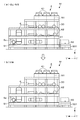
- 3 (a) and 3 (b) a state in which the power supply device in the side-by-side building 50, which is a substation, and the power consumption device ACHE 41 and the pump 6a are connected by a feeder line 51 indicated by a broken line. Is shown.
- the module M is installed in the frame 30 or the parallel building 50 at a factory or the like different from the construction site of the NG liquefaction device, and each device is installed by the feeder 51 and the signal line. Are connected to each other, and the frame 30 and the parallel building 50 are connected via the connecting member 31 (FIG. 3A).
- the module M which has been completed, is transported to the construction site using a carrier ship or a transport vehicle in an integrated state in which the frame 30 and the additional building 50 are connected (FIG. 3 (a)).
- the module M is placed on a foundation prepared in advance in the construction site of the NG liquefier, the lower end of the frame 30 and the lower end of the base 501 of the parallel building 50 are fixed to the foundation and the module M is installed.
- the frame 30 and the parallel building 50 are connected to correspond to the positional relationship after installation on the construction site, only by transporting the module M to a predetermined position, The frame 30 and the parallel building 50 can be arranged at an accurate position.
- the parallel building 50 separated from the frame 30 is installed outside the frame 30 and at a position separated from the frame 30 by a necessary distance.
- the explosion proof structure required for the additional building 50 and the base portion 501 supporting the same is limited to only this range, and the frame 30 does not have to be an explosion proof structure.
- a plurality of modules M corresponding to the respective processing units 11 to 16 are respectively installed at predetermined positions, and other devices such as the refrigerant compressor 21 are installed.
- a plurality of modules M are arranged in two rows on the near side and the far side, with the parallel buildings 50 arranged on the rear end side of each structure 30 facing each other in the front and back direction.
- the position of the additional building 50 may be disposed on the front end side with respect to the frame 30.
- FIG. 2 shows an example in which one additional building 50 is provided for each structure 30, a plurality of additional buildings 50 for the transformation room and the equipment control room are connected to the structure 30, M may be built and transported.
- the module M is installed at a predetermined position, the connecting member 31 is removed, piping is connected between the modules M or between devices outside the module M, power generation facilities, and so on.
- the NG liquefaction apparatus can be configured by connecting a feed line to the main control room and connecting a signal line between the central control room and each parallel building 50 which is an equipment control room.
- the module M according to the present embodiment has the following effects. Since the frame 30 accommodating the device group constituting a part of the NG gas liquefier and the parallel building 50 accommodating the power supply device or the control information output device are connected via the connecting member 31, the module M At the time of transportation, it becomes easy to transport the frame 30 and the parallel building 50 integrally. In addition, after the module M is installed on the construction site of the NG gas liquefier, the frame 30 and the parallel building 50 are separated by removing the connecting member 31. Optimal design and construction of the module M can be performed under less restrictive conditions without being subject to any problems.
- the parallel building 50 is disposed outside the structure 30, and the side surface of the structure 30 and the side surface of the parallel building 50 (base portion 501) are connected by the connecting member 31.
- An example is shown.
- the connection position of the parallel building 50 with respect to the frame 30 is not limited to the example.
- the frame 30 and the additional building 50 are connected via the connecting member 31 in a state where the additional building 50 is accommodated in the structure 30 (for example, the space below the piping 42). May be built.
- the module M can be transported in a more compact state.
- M M 'module (module for NG liquefier) 11 Gas-Liquid Separation Unit 12 Mercury Removal Unit 13 Acidic Gas Removal Unit 14 Water Removal Unit 15 Liquefaction Treatment Unit 16 Refractiveization Unit 30, 30a Frame 31 connecting member 41 ACHE 50 parallel building 51 feeder 6 frame internal equipment 6a pump
Landscapes
- Engineering & Computer Science (AREA)
- Physics & Mathematics (AREA)
- Mechanical Engineering (AREA)
- Thermal Sciences (AREA)
- General Engineering & Computer Science (AREA)
- Architecture (AREA)
- Chemical Kinetics & Catalysis (AREA)
- General Chemical & Material Sciences (AREA)
- Oil, Petroleum & Natural Gas (AREA)
- Chemical & Material Sciences (AREA)
- Civil Engineering (AREA)
- Structural Engineering (AREA)
- Separation By Low-Temperature Treatments (AREA)
Abstract
Description
近年、NG液化装置を建設するにあたり、NG液化装置を構成する多数の機器をブロック分けし、各ブロックの機器群を共通の架構内に組み込むモジュール化の取り組みがなされている(例えば特許文献1)。以下、NG液化装置を建設するためのモジュールを天然ガス液化装置用モジュール(NG液化装置用モジュール)と呼ぶ。
電力消費機器に対する電力の供給について、NG液化装置用モジュールには、電圧変換を行う変電器や、各電力消費機器への給電制御を行う給電制御設備、遮断機や断路器などの電力供給機器を備えた変電室(Substation)が併設される場合がある。
前記架構とは別に設けられ、前記機器群に含まれる電力消費機器に対して電力を供給する電力供給機器、または、前記機器群に含まれ、制御信号を用いて被制御機器の動作制御を行うコントローラに対して、前記動作制御に係る情報を出力する制御情報出力機器の少なくとも一方を収容した併設建屋と、
前記天然ガス液化装置用モジュールの輸送時に、前記架構と併設建屋とを一体として輸送可能なようにこれら架構と併設建屋とを連結し、当該天然ガス液化装置用モジュールを前記天然ガス液化装置の建設地に設置する際に、架構と併設建屋とを分離するために取り外される連結部材と、を備えたことを特徴とする。
(a)前記連結部材を介して架構と併設建屋とが連結された状態の前記天然ガス液化装置用モジュールは、前記併設建屋に電力供給機器が設けられている場合には、当該電力供給機器と、電力の供給先の電力消費機器とが給電線を介して接続され、前記併設建屋に制御情報出力機器が設けられている場合には、当該制御情報出力機器と、動作制御に係る情報の出力先のコントローラとが信号線を介して接続されていること。
(b)前記天然ガス装置用モジュールを建設地に設置して前記連結部材を取り外すと、前記架構及び併設建屋が各々の設置位置に配置された状態となるように、当該連結部材は、前記架構の側面と併設建屋の側面とを連結すること。
(c)前記併設建屋は耐爆構造を有する一方、前記架構は耐爆構造を有しないこと。
また、本発明の天然ガス液化装置は、上述した複数の天然ガス液化装置用モジュールが、各々、前記連結部材を取り外された状態で設置されていることを特徴とする。
前記天然ガス液化装置用モジュールの建造地から、前記天然ガス液化装置の建設地へと、当該天然ガス液化装置用モジュールを輸送する工程と、
前記建設地へと輸送された天然ガス液化装置用モジュールを当該建設地内に設置する際に、前記連結部材を取り外して、前記架構と併設建屋とを分離する工程と、を含むことを特徴とする。
(d)前記天然ガス液化装置用モジュールを建造する工程は、前記併設建屋に電力供給機器が設けられている場合には、当該電力供給機器と、電力の供給先の電力消費機器とを給電線を介して接続し、前記併設建屋に制御情報出力機器が設けられている場合には、当該制御情報出力機器と、動作制御に係る情報の出力先のコントローラとを信号線を介して接続する工程を含むこと。
(e)前記連結部材は、前記架構の側面と併設建屋の側面とを連結し、前記架構と併設建屋とを分離する工程にて、前記連結部材を取り外すと、前記架構及び併設建屋が各々の設置位置に配置された状態となること。
(f)前記天然ガス液化装置用モジュールを建造する工程は、耐爆構造を有する前記併設建屋を構成する工程と、耐爆構造を有しない鉄骨製の骨組み構造により前記架構を構成する工程と、を含むこと。
また、天然ガス液化装置の建設地に天然ガス液化装置用モジュールを設置した後には連結部材を取り外すことにより架構と併設建屋とが分離されるので、設計規格の違いなどの影響を受けずに、より制約の少ない条件下で天然ガス液化装置用モジュールの構造物設計、建造を行うことができる。
NG液化装置は、NGから液体を分離する気液分離部11と、NG中の水銀の除去を行う水銀除去部12と、NGから二酸化炭素や硫化水素などの酸性ガスを除去する酸性ガス除去部13と、NGに含まれる微量の水分を除去する水分除去部14と、これらの不純物が除去されたNGを冷却、液化してLNGを得る液化処理部15と、液化されたLNGを貯蔵する貯蔵タンク17とを備える。
また、ガス分離膜が採用されている場合、酸性ガス除去部13は、本体内に多数本の中空糸膜を収容したガス分離ユニットやその付帯設備などの機器群を備える。
また図1には、冷媒圧縮機21を駆動する動力源としてガスタービン22を用いた例を示してあるが、冷媒圧縮機21の規模などに応じてモーターなどを用いてもよい。
以下の説明では、図2中に実線で示した座標軸のY軸の基点側を手前側、矢印方向側を奥手側と呼ぶ。また、図2~4中に破線で示した副座標軸は、各モジュールMに着目した方向を示し、副座標軸のY’軸の基点側を後端側、矢印方向側を先端側と呼ぶ。
そこでこれらの電力消費機器を収容した架構30には、電圧変換を行う変電器や、各電力消費機器への給電制御を行う給電制御設備、遮断機や断路器などの電力供給機器を備えた変電室が併設される。
制御情報出力機器と、各被制御機器のコントローラや検出部とは、信号線を介して接続されている。また以下の説明では、上述の変電室や機器制御室を併設建屋50とも呼ぶ。
NG液化装置の建設にあたっては、当該NG液化装置の建設地とは異なる工場などでモジュールMを建造し、完成したモジュールMを運搬船や輸送車にて建設地まで輸送した後、当該建設地に設置する作業が実施される。
このため、架構30と併設建屋50とを別々に輸送して建設地に設置した後、給電線や信号線の繋ぎ込み作業を行うよりも、モジュールMの建造時にこれら架構30や併設建屋50を一緒に建造し、給電線や信号線の繋ぎ込みも完了させておいた方が、モジュールMを建設地に設置した後の工数を大幅に低減できる。
上述の構成のモジュールM’を建造して、架構30aと併設建屋50とを一体に輸送し、建設地に設置すれば、給電線や信号線の繋ぎ込み作業は殆ど発生しないので、その後の工数を大幅に低減できる。
なお、架構30aの上面に併設建屋50を配置する図4の例に替えて、例えば架構30aの後端側の配管42の下方側の空間に併設建屋50を配置すれば、併設建屋50の耐爆荷重を支えるための架構30aの鉄骨部材断面を大きくしなければならない範囲は、低層部分のみに限定することができる。しかしながら、依然として大きな範囲の強固な架構構造が必要なうえに、建造工程上、配管42の据え付けの前に併設建屋を架構30a内に据え付ける必要があり、工程管理を難しくするという新たな問題も発生する。
詳細には図3(a)に示すように、本例のモジュールMは、建設地への設置後の位置関係に対応させて架構30の後端側の側方位置に併設建屋50を配置し、架構30の側面と、併設建屋50を支持する基台部501の側面とを連結部材31を介して連結した構造となっている。
なお、図3(a)、(b)には、変電室である併設建屋50内の電力供給機器と、電力消費機器であるACHE41やポンプ6aとが破線で示す給電線51によって接続された状態を示してある。
建造が完了したモジュールMは、架構30と併設建屋50とが連結された一体の状態にて、運搬船や輸送車を用いて建設地まで輸送される(図3(a))。
このとき、既述のように建設地への設置後の位置関係に対応させて架構30と併設建屋50とが連結されているので、予め設定された位置にモジュールMを輸送するだけで、これら架構30及び併設建屋50を正確な位置に配置することができる。
なお、連結部材31を取り外す順序に特段の限定はなく、モジュールMを設置位置の近傍まで輸送した後、連結部材31を切り離してから、架構30及び併設建屋50の正確な位置合わせを行ってもよい。
図2に示す例では、各架構30の後端側に配置された併設建屋50を前後に対向させた状態にて、複数のモジュールMが手前側及び奥手側の2列に並べられているが、併設建屋50の位置は架構30に対して前端側に配置されてもよい。
図2には、各架構30に対して併設建屋50を1つずつ設けた例を示したが、変電室用及び機器制御室用の複数の併設建屋50を架構30に対して連結し、モジュールMの建造、輸送を行ってもよい。
NGガス液化装置の一部を構成する機器群を収容した架構30と、電力供給機器または制御情報出力機器を収容した併設建屋50とが連結部材31を介して連結されているので、モジュールMの輸送時に、これら架構30と併設建屋50とを一体に輸送することが容易となる。
また、NGガス液化装置の建設地にモジュールMを設置した後には連結部材31を取り外すことにより架構30と併設建屋50とが分離されるので、互いの構造物の設計規格の違いなどの影響を受けずに、より制約の少ない条件下でモジュールMの最適設計、建造を行うことができる。
11 気液分離部
12 水銀除去部
13 酸性ガス除去部
14 水分除去部
15 液化処理部
16 精留部
30、30a
架構
31 連結部材
41 ACHE
50 併設建屋
51 給電線
6 架構内機器
6a ポンプ
Claims (9)
- 天然ガス液化装置用モジュールにおいて、
前記天然ガス液化装置の一部を構成する機器群を収容した架構と、
前記架構とは別に設けられ、前記機器群に含まれる電力消費機器に対して電力を供給する電力供給機器、または、前記機器群に含まれ、制御信号を用いて被制御機器の動作制御を行うコントローラに対して、前記動作制御に係る情報を出力する制御情報出力機器の少なくとも一方を収容した併設建屋と、
前記天然ガス液化装置用モジュールの輸送時に、前記架構と併設建屋とを一体として輸送可能なようにこれら架構と併設建屋とを連結し、当該天然ガス液化装置用モジュールを前記天然ガス液化装置の建設地に設置する際に、架構と併設建屋とを分離するために取り外される連結部材と、を備えたことを特徴とする天然ガス液化装置用モジュール。 - 前記連結部材を介して架構と併設建屋とが連結された状態の前記天然ガス液化装置用モジュールは、
前記併設建屋に電力供給機器が設けられている場合には、当該電力供給機器と、電力の供給先の電力消費機器とが給電線を介して接続され、
前記併設建屋に制御情報出力機器が設けられている場合には、当該制御情報出力機器と、動作制御に係る情報の出力先のコントローラとが信号線を介して接続されていることを特徴とする請求項1に記載の天然ガス液化装置用モジュール。 - 前記天然ガス装置用モジュールを建設地に設置して前記連結部材を取り外すと、前記架構及び併設建屋が各々の設置位置に配置された状態となるように、当該連結部材は、前記架構の側面と併設建屋の側面とを連結することを特徴とする請求項1に記載の天然ガス液化装置用モジュール。
- 前記併設建屋は耐爆構造を有する一方、前記架構は耐爆構造を有しないことを特徴とする請求項1に記載の天然ガス液化装置用モジュール。
- 請求項1ないし4のいずれか一つに記載の複数の天然ガス液化装置用モジュールが、各々、前記連結部材を取り外された状態で設置されていることを特徴とする天然ガス液化装置。
- 天然ガス液化装置の製造方法において、
前記天然ガス液化装置の一部を構成する機器群を収容した架構と、前記架構とは別に設けられ、前記機器群に含まれる電力消費機器に対して電力を供給する電力供給機器、または、前記機器群に含まれ、制御信号を用いて被制御機器の動作制御を行うコントローラに対して、前記動作制御に係る情報を出力する制御情報出力機器の少なくとも一方を収容した併設建屋と、前記天然ガス液化装置用モジュールの輸送時に、前記架構と併設建屋とを一体として輸送可能なようにこれら架構と併設建屋とを連結する連結部材と、を備えた天然ガス液化装置用モジュールを建造する工程と、
前記天然ガス液化装置用モジュールの建造地から、前記天然ガス液化装置の建設地へと、当該天然ガス液化装置用モジュールを輸送する工程と、
前記建設地へと輸送された天然ガス液化装置用モジュールを当該建設地内に設置する際に、前記連結部材を取り外して、前記架構と併設建屋とを分離する工程と、を含むことを特徴とする天然ガス液化装置の製造方法。 - 前記天然ガス液化装置用モジュールを建造する工程は、
前記併設建屋に電力供給機器が設けられている場合には、当該電力供給機器と、電力の供給先の電力消費機器とを給電線を介して接続し、前記併設建屋に制御情報出力機器が設けられている場合には、当該制御情報出力機器と、動作制御に係る情報の出力先のコントローラとを信号線を介して接続する工程を含むことを特徴とする請求項6に記載の天然ガス液化装置の製造方法。 - 前記連結部材は、前記架構の側面と併設建屋の側面とを連結し、
前記架構と併設建屋とを分離する工程にて、前記連結部材を取り外すと、前記架構及び併設建屋が各々の設置位置に配置された状態となることを特徴とする請求項6に記載の天然ガス液化装置の製造方法。 - 前記天然ガス液化装置用モジュールを建造する工程は、
耐爆構造を有する前記併設建屋を構成する工程と、
耐爆構造を有しない鉄骨製の骨組み構造により前記架構を構成する工程と、を含むことを特徴とする請求項6に記載の天然ガス液化装置の製造方法。
Priority Applications (5)
| Application Number | Priority Date | Filing Date | Title |
|---|---|---|---|
| AU2017422728A AU2017422728B2 (en) | 2017-07-06 | 2017-07-06 | Module for natural gas liquefaction devices, natural gas liquefaction device, and method for manufacturing natural gas liquefaction devices |
| RU2019130807A RU2727948C1 (ru) | 2017-07-06 | 2017-07-06 | Модуль для устройств сжижения природного газа, устройство сжижения природного газа и способ производства устройств сжижения природного газа |
| CA3054113A CA3054113C (en) | 2017-07-06 | 2017-07-06 | Module for natural gas liquefaction devices, natural gas liquefaction device, and method for manufacturing natural gas liquefaction devices |
| US16/497,796 US11371774B2 (en) | 2017-07-06 | 2017-07-06 | Module for natural gas liquefaction devices, natural gas liquefaction device, and method for manufacturing natural gas liquefaction devices |
| PCT/JP2017/024814 WO2019008725A1 (ja) | 2017-07-06 | 2017-07-06 | 天然ガス液化装置用モジュール、天然ガス液化装置、及び天然ガス液化装置の製造方法 |
Applications Claiming Priority (1)
| Application Number | Priority Date | Filing Date | Title |
|---|---|---|---|
| PCT/JP2017/024814 WO2019008725A1 (ja) | 2017-07-06 | 2017-07-06 | 天然ガス液化装置用モジュール、天然ガス液化装置、及び天然ガス液化装置の製造方法 |
Publications (1)
| Publication Number | Publication Date |
|---|---|
| WO2019008725A1 true WO2019008725A1 (ja) | 2019-01-10 |
Family
ID=64950705
Family Applications (1)
| Application Number | Title | Priority Date | Filing Date |
|---|---|---|---|
| PCT/JP2017/024814 Ceased WO2019008725A1 (ja) | 2017-07-06 | 2017-07-06 | 天然ガス液化装置用モジュール、天然ガス液化装置、及び天然ガス液化装置の製造方法 |
Country Status (5)
| Country | Link |
|---|---|
| US (1) | US11371774B2 (ja) |
| AU (1) | AU2017422728B2 (ja) |
| CA (1) | CA3054113C (ja) |
| RU (1) | RU2727948C1 (ja) |
| WO (1) | WO2019008725A1 (ja) |
Cited By (6)
| Publication number | Priority date | Publication date | Assignee | Title |
|---|---|---|---|---|
| JPWO2020245868A1 (ja) * | 2019-06-03 | 2020-12-10 | ||
| WO2021024376A1 (ja) * | 2019-08-06 | 2021-02-11 | 日揮グローバル株式会社 | 天然ガスプラント用モジュール |
| WO2021106151A1 (ja) * | 2019-11-28 | 2021-06-03 | 日揮グローバル株式会社 | 洋上プラント用構造物 |
| KR20220048425A (ko) | 2020-10-12 | 2022-04-19 | 닛키 글로벌 가부시키가이샤 | 건물의 설치 기구, 및 건물의 설치 방법 |
| RU2794742C1 (ru) * | 2019-09-26 | 2023-04-24 | ДжГК Корпорейшн | Способ изготовления станции для преобразования энергии и станция для преобразования энергии |
| US12034280B2 (en) | 2019-11-13 | 2024-07-09 | Chiyoda Corporation | Plant module, plant including the same, and operation method of plant |
Families Citing this family (1)
| Publication number | Priority date | Publication date | Assignee | Title |
|---|---|---|---|---|
| CA3083578A1 (en) * | 2017-12-07 | 2019-06-13 | Shell Internationale Research Maatschappij B.V. | Compact lng production train and method |
Citations (3)
| Publication number | Priority date | Publication date | Assignee | Title |
|---|---|---|---|---|
| WO2014028961A1 (en) * | 2012-08-22 | 2014-02-27 | Woodside Energy Technologies Pty Ltd | Modular lng production facility |
| JP2016514823A (ja) * | 2013-03-27 | 2016-05-23 | ウッドサイド エナジー テクノロジーズ プロプライエタリー リミテッド | 空冷式モジュール型lng生産設備 |
| WO2017062155A1 (en) * | 2015-10-06 | 2017-04-13 | Exxonmobil Upstream Research Company | Modularization of a hydrocarbon processing plant |
Family Cites Families (13)
| Publication number | Priority date | Publication date | Assignee | Title |
|---|---|---|---|---|
| US4992669A (en) * | 1989-02-16 | 1991-02-12 | Parmley Daniel W | Modular energy system |
| US7221061B2 (en) * | 2002-12-02 | 2007-05-22 | Caterpillar Inc | Power generation system having an external process module |
| US10787803B2 (en) * | 2008-02-02 | 2020-09-29 | Charles H. Leahy | Methods and systems for modular buildings |
| US20090223144A1 (en) * | 2008-02-02 | 2009-09-10 | Leahy Charles H | Methods & systems for modular buildings |
| US20090229194A1 (en) * | 2008-03-11 | 2009-09-17 | Advanced Shielding Technologies Europe S.I. | Portable modular data center |
| US8251785B2 (en) * | 2008-10-31 | 2012-08-28 | Cirrus Logic, Inc. | System and method for vertically stacked information handling system and infrastructure enclosures |
| US9670689B2 (en) * | 2010-04-06 | 2017-06-06 | Schneider Electric It Corporation | Container based data center solutions |
| US8587136B2 (en) * | 2010-12-20 | 2013-11-19 | Solar Turbines Inc. | Mobile power system |
| RU2451252C1 (ru) * | 2011-03-22 | 2012-05-20 | Закрытое акционерное общество Финансовая компания "Центр Космос-Нефть-Газ" | Способ монтажа блок-модуля установки комплексной подготовки газа на газовом промысле нефтегазоконденсатного месторождения |
| US9945142B2 (en) * | 2011-04-06 | 2018-04-17 | Fmr Llc | Modular data center |
| WO2013000985A2 (en) * | 2011-06-28 | 2013-01-03 | Dsm Ip Assets B.V. | Modular multi-story production plant and methods for constructing same |
| RU2561962C1 (ru) * | 2014-07-22 | 2015-09-10 | Открытое акционерное общество "Татнефть" им. В.Д. Шашина | Блок сепарации газа |
| US9939194B2 (en) * | 2014-10-21 | 2018-04-10 | Kellogg Brown & Root Llc | Isolated power networks within an all-electric LNG plant and methods for operating same |
-
2017
- 2017-07-06 WO PCT/JP2017/024814 patent/WO2019008725A1/ja not_active Ceased
- 2017-07-06 CA CA3054113A patent/CA3054113C/en active Active
- 2017-07-06 US US16/497,796 patent/US11371774B2/en active Active
- 2017-07-06 AU AU2017422728A patent/AU2017422728B2/en active Active
- 2017-07-06 RU RU2019130807A patent/RU2727948C1/ru active
Patent Citations (3)
| Publication number | Priority date | Publication date | Assignee | Title |
|---|---|---|---|---|
| WO2014028961A1 (en) * | 2012-08-22 | 2014-02-27 | Woodside Energy Technologies Pty Ltd | Modular lng production facility |
| JP2016514823A (ja) * | 2013-03-27 | 2016-05-23 | ウッドサイド エナジー テクノロジーズ プロプライエタリー リミテッド | 空冷式モジュール型lng生産設備 |
| WO2017062155A1 (en) * | 2015-10-06 | 2017-04-13 | Exxonmobil Upstream Research Company | Modularization of a hydrocarbon processing plant |
Cited By (12)
| Publication number | Priority date | Publication date | Assignee | Title |
|---|---|---|---|---|
| JPWO2020245868A1 (ja) * | 2019-06-03 | 2020-12-10 | ||
| WO2020245868A1 (ja) * | 2019-06-03 | 2020-12-10 | 日揮グローバル株式会社 | プラント建設用モジュール、プラント、プラント建設用モジュールの製造方法、及びプラントの建設方法 |
| JP7238117B2 (ja) | 2019-06-03 | 2023-03-13 | 日揮グローバル株式会社 | プラント建設用モジュール、プラント、プラント建設用モジュールの製造方法、及びプラントの建設方法 |
| US11795682B2 (en) | 2019-06-03 | 2023-10-24 | Jgc Corporation | Plant construction module, plant, manufacturing method for plant construction module, and plant construction method |
| WO2021024376A1 (ja) * | 2019-08-06 | 2021-02-11 | 日揮グローバル株式会社 | 天然ガスプラント用モジュール |
| CN112912678A (zh) * | 2019-08-06 | 2021-06-04 | 日挥环球株式会社 | 天然气设备用模块 |
| JP6887071B1 (ja) * | 2019-08-06 | 2021-06-16 | 日揮グローバル株式会社 | 天然ガスプラント用モジュール |
| RU2766682C1 (ru) * | 2019-08-06 | 2022-03-15 | ДжГК Корпорейшн | Модуль для завода по переработке природного газа |
| RU2794742C1 (ru) * | 2019-09-26 | 2023-04-24 | ДжГК Корпорейшн | Способ изготовления станции для преобразования энергии и станция для преобразования энергии |
| US12034280B2 (en) | 2019-11-13 | 2024-07-09 | Chiyoda Corporation | Plant module, plant including the same, and operation method of plant |
| WO2021106151A1 (ja) * | 2019-11-28 | 2021-06-03 | 日揮グローバル株式会社 | 洋上プラント用構造物 |
| KR20220048425A (ko) | 2020-10-12 | 2022-04-19 | 닛키 글로벌 가부시키가이샤 | 건물의 설치 기구, 및 건물의 설치 방법 |
Also Published As
| Publication number | Publication date |
|---|---|
| CA3054113C (en) | 2023-09-12 |
| CA3054113A1 (en) | 2019-01-10 |
| AU2017422728B2 (en) | 2023-04-13 |
| AU2017422728A1 (en) | 2019-08-29 |
| RU2727948C1 (ru) | 2020-07-27 |
| US11371774B2 (en) | 2022-06-28 |
| US20200300540A1 (en) | 2020-09-24 |
Similar Documents
| Publication | Publication Date | Title |
|---|---|---|
| WO2019008725A1 (ja) | 天然ガス液化装置用モジュール、天然ガス液化装置、及び天然ガス液化装置の製造方法 | |
| US10060670B2 (en) | Air-cooled modular LNG production facility | |
| KR101915007B1 (ko) | 모듈로 조립된 콤팩트한 액화천연가스 생산설비 | |
| AU2016335111B2 (en) | Modularization of a hydrocarbon processing plant | |
| JP2015522782A (ja) | コア交換用のコールドボックス設計 | |
| US11408677B2 (en) | Module for natural gas liquefier apparatus and natural gas liquefier apparatus | |
| WO2016092593A1 (ja) | 天然ガスの液化システム | |
| WO2018180549A1 (ja) | プラントの建設方法 | |
| AU2017419936B2 (en) | Natural gas liquefaction device | |
| KR102485278B1 (ko) | 천연가스 플랜트용 모듈 | |
| AU2013202033A1 (en) | Modular lng production facility | |
| US20230392860A1 (en) | Compact system and method for the production of liquefied natural gas | |
| JP2020159647A (ja) | 天然ガス液化装置 | |
| CA3057262C (en) | Module for natural gas liquefier apparatus and natural gas liquefier apparatus | |
| WO2020075295A1 (ja) | 天然ガス液化装置 |
Legal Events
| Date | Code | Title | Description |
|---|---|---|---|
| 121 | Ep: the epo has been informed by wipo that ep was designated in this application |
Ref document number: 17916883 Country of ref document: EP Kind code of ref document: A1 |
|
| ENP | Entry into the national phase |
Ref document number: 3054113 Country of ref document: CA |
|
| ENP | Entry into the national phase |
Ref document number: 2017422728 Country of ref document: AU Date of ref document: 20170706 Kind code of ref document: A |
|
| NENP | Non-entry into the national phase |
Ref country code: DE |
|
| 122 | Ep: pct application non-entry in european phase |
Ref document number: 17916883 Country of ref document: EP Kind code of ref document: A1 |
|
| NENP | Non-entry into the national phase |
Ref country code: JP |