WO2019003804A1 - 眼科装置、及びその制御方法 - Google Patents
眼科装置、及びその制御方法 Download PDFInfo
- Publication number
- WO2019003804A1 WO2019003804A1 PCT/JP2018/021305 JP2018021305W WO2019003804A1 WO 2019003804 A1 WO2019003804 A1 WO 2019003804A1 JP 2018021305 W JP2018021305 W JP 2018021305W WO 2019003804 A1 WO2019003804 A1 WO 2019003804A1
- Authority
- WO
- WIPO (PCT)
- Prior art keywords
- image
- light
- scan
- displacement
- scanner
- Prior art date
- Legal status (The legal status is an assumption and is not a legal conclusion. Google has not performed a legal analysis and makes no representation as to the accuracy of the status listed.)
- Ceased
Links
Images






Classifications
-
- A—HUMAN NECESSITIES
- A61—MEDICAL OR VETERINARY SCIENCE; HYGIENE
- A61B—DIAGNOSIS; SURGERY; IDENTIFICATION
- A61B3/00—Apparatus for testing the eyes; Instruments for examining the eyes
- A61B3/10—Objective types, i.e. instruments for examining the eyes independent of the patients' perceptions or reactions
- A61B3/12—Objective types, i.e. instruments for examining the eyes independent of the patients' perceptions or reactions for looking at the eye fundus, e.g. ophthalmoscopes
-
- A—HUMAN NECESSITIES
- A61—MEDICAL OR VETERINARY SCIENCE; HYGIENE
- A61B—DIAGNOSIS; SURGERY; IDENTIFICATION
- A61B3/00—Apparatus for testing the eyes; Instruments for examining the eyes
- A61B3/10—Objective types, i.e. instruments for examining the eyes independent of the patients' perceptions or reactions
- A61B3/12—Objective types, i.e. instruments for examining the eyes independent of the patients' perceptions or reactions for looking at the eye fundus, e.g. ophthalmoscopes
- A61B3/1225—Objective types, i.e. instruments for examining the eyes independent of the patients' perceptions or reactions for looking at the eye fundus, e.g. ophthalmoscopes using coherent radiation
-
- A—HUMAN NECESSITIES
- A61—MEDICAL OR VETERINARY SCIENCE; HYGIENE
- A61B—DIAGNOSIS; SURGERY; IDENTIFICATION
- A61B3/00—Apparatus for testing the eyes; Instruments for examining the eyes
- A61B3/10—Objective types, i.e. instruments for examining the eyes independent of the patients' perceptions or reactions
- A61B3/102—Objective types, i.e. instruments for examining the eyes independent of the patients' perceptions or reactions for optical coherence tomography [OCT]
-
- A—HUMAN NECESSITIES
- A61—MEDICAL OR VETERINARY SCIENCE; HYGIENE
- A61B—DIAGNOSIS; SURGERY; IDENTIFICATION
- A61B3/00—Apparatus for testing the eyes; Instruments for examining the eyes
- A61B3/10—Objective types, i.e. instruments for examining the eyes independent of the patients' perceptions or reactions
- A61B3/1025—Objective types, i.e. instruments for examining the eyes independent of the patients' perceptions or reactions for confocal scanning
-
- A—HUMAN NECESSITIES
- A61—MEDICAL OR VETERINARY SCIENCE; HYGIENE
- A61B—DIAGNOSIS; SURGERY; IDENTIFICATION
- A61B3/00—Apparatus for testing the eyes; Instruments for examining the eyes
- A61B3/10—Objective types, i.e. instruments for examining the eyes independent of the patients' perceptions or reactions
- A61B3/14—Arrangements specially adapted for eye photography
Definitions
- the present invention relates to an ophthalmologic apparatus and a control method thereof.
- OCT optical coherence tomography
- SLO scanning laser ophthalmoscope
- tracking is an important technique for acquiring a high-definition image regardless of eye movement of a target eye.
- Tracking is to move the device optical system in accordance with the eye movement of the target eye.
- alignment and focusing are performed in advance.
- the tracking is a function of maintaining a suitable positional relationship in which the alignment and the focus are in focus by making the position of the apparatus optical system follow the eye movement.
- Various techniques related to such tracking have been proposed.
- Patent Document 1 the base image and the target image of the fundus are acquired using the SLO optical system, the difference (displacement amount) between a plurality of target areas in each image is obtained, and the sum of the obtained differences is An ophthalmologic apparatus is disclosed that performs tracking control to a minimum.
- a fundus camera is used to obtain a base image and a target image of a fundus, and a phase limited correlation process is performed on the base image and the target image to obtain a slight positional deviation amount.
- An ophthalmologic apparatus is disclosed that performs tracking control based on a positional displacement amount.
- the SLO optical system is used to acquire a target image of the same size as the base image, so it takes time to scan the fundus, and the eye movement during that time It may not be possible to follow the position etc.
- the target image can be acquired in a short time, and the position of the apparatus optical system can follow the eye movement with high accuracy.
- the position of the apparatus optical system may not be able to follow the eye movement during that time.
- the present invention has been made in view of such circumstances, and an object thereof is an ophthalmologic apparatus capable of high-speed and highly accurate tracking control even when acquiring an image using an SLO optical system, and It is in providing the control method.
- a first aspect of the embodiment includes a first light scanner for deflecting a first light, and an SLO system for scanning a target eye with the first light deflected by the first light scanner, and for deflecting a second light.
- a projection system that includes a second light scanner and projects the second light deflected by the second light scanner onto the target eye, and the scan result of the first scan area using the first light scanner
- a second image of the target eye is generated based on a scan result of a second scan area narrower than the first scan area using a first image forming unit for forming a first image of the target eye and the first light scanner.
- the second image forming unit to be formed a displacement processing unit that calculates a displacement between the partial image corresponding to the second image in the first image, and the second image, and the above calculated by the displacement processing unit Said second based on the displacement
- a control unit for controlling the optical scanner is a ophthalmologic apparatus including a.
- control unit may correct the projection position of the second light by the projection system based on the displacement.
- the second image is obtained by dividing the first image in a first scan direction by the SLO system. It may be an image corresponding to one of the above partial images.
- sizes of the two or more partial images in the first scan direction may be the same.
- control unit repeatedly scans while changing the position of the second scan area in the target eye.
- the second light scanner may be controlled based on
- control unit repeats scanning of the second scan area by the SLO system so as to scan the entire first scan area. It may be performed by
- the displacement processing unit performs phase limited correlation processing on the partial image and the second image.
- the parallel movement amount and the parallel movement direction between the partial image and the second image, and the rotational movement amount and the rotational movement direction between the partial image and the second image are calculated. May be
- the projection system according to any one of the first to seventh aspects, wherein the second light is a measurement light based on OCT light from an OCT light source.
- the target includes an OCT system that projects light onto the target eye via an optical scanner and receives interference light between the return light and reference light based on the OCT light, and the target is based on the result of reception of the interference light by the OCT system. It may include a third image forming unit that forms a tomogram of the eye.
- the projection system includes a laser irradiation system which irradiates the target eye with a laser beam output from a light source. May be.
- the tenth aspect of the embodiment includes a first light scanner for deflecting a first light, and an SLO system for scanning a target eye with the first light deflected by the first light scanner, and a first light
- a control method of an ophthalmologic apparatus comprising: a second light scanner that deflects, and a projection system that projects the second light deflected by the second light scanner onto the target eye.
- a control step of controlling the second optical scanner based on the serial displacement processing said displacement calculated in step a control method for an ophthalmologic apparatus including a.
- the projection position of the second light by the projection system may be corrected based on the displacement in the control step.
- control step scanning is repeatedly performed while changing the position of the second scan area with respect to the target eye.
- control the SLO system to form the second image in the second image forming step each time the scanning of the second scan region is completed, and calculate the displacement in the displacement processing step;
- the second light scanner may be controlled based on the displacement.
- an ophthalmologic apparatus capable of performing high-speed and highly accurate tracking control even when acquiring an image using the SLO optical system, and a control method thereof.
- the ophthalmologic apparatus includes an SLO system as a fundus observation system (imaging system), and light of a projection system based on (fundus) images of a target eye (eye to be examined, patient's eye) acquired using the SLO system.
- SLO system a fundus observation system
- the OCT system includes an optical scanner and an interference optical system.
- the interference optical system divides the light from the OCT light source into the measurement light and the reference light, irradiates the measurement light to the target eye, and refers to the return light of the measurement light from the target eye (fundus oculi) and the reference light path.
- Interference light with light is generated, and the generated interference light is detected.
- the measurement light is deflected by an optical scanner.
- the laser irradiation system includes an optical scanner and an irradiation optical system.
- the irradiation optical system is an optical system that guides the laser light from the laser light source to the target eye.
- laser light is deflected by an optical scanner.
- the left and right direction is the X direction when viewed from the subject
- the vertical direction is the Y direction
- the depth direction of the optical system is viewed as the Z direction when viewed from the subject.
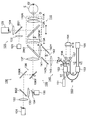
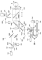
- Optical system 1 to 3 show an example of the configuration of the optical system of the ophthalmologic apparatus according to the embodiment.
- the ophthalmologic apparatus according to the embodiment can acquire an image of an eye to be examined in a range corresponding to the imaging mode.
- the imaging mode includes a wide-angle imaging mode for capturing an image of the eye E in a first range (for example, an angle of view of 100 degrees) and a second range (for example, an angle of view of 50 degrees) narrower than the first range.
- a high magnification photographing mode for photographing the image of the eye E to be examined.
- the ophthalmologic apparatus can selectively arrange an objective lens unit corresponding to a photographing mode on the optical axis of the optical system.
- FIG. 1 shows an example of the configuration of the optical system of the ophthalmologic apparatus when the wide-angle shooting mode is set.
- FIG. 2 shows an example of the configuration of an objective lens system according to an embodiment that can be switched according to the imaging mode.
- FIG. 3 shows a configuration example of an optical system of the ophthalmologic apparatus when the high magnification shooting mode is set. In FIG. 3, the same parts as in FIG. 1 or FIG. In FIGS.
- a position optically conjugate to the fundus Ef of the eye E to be examined is illustrated as a fundus conjugate position P
- a position optically conjugate to a pupil of the eye to be examined E is illustrated as a pupil conjugate position Q There is.
- the optical system 100 includes a projection system that projects light onto the eye to be examined via the objective lens system 110, and a light reception system that receives return light of light projected onto the eye to be examined E by the projection system via the objective lens system 110. including.
- the ophthalmologic apparatus forms an image based on the result of light reception by the light reception system.
- the ophthalmologic apparatus according to the embodiment can form an SLO image and an OCT image.
- Such an optical system 100 includes an SLO optical system 130 and an OCT optical system 140.
- the SLO optical system 130 includes an SLO projection system and an SLO light reception system.
- the OCT optical system 140 includes an OCT projection system and an OCT light receiving system.
- the above laser irradiation system may be provided in the projection system of the optical system 100.
- the projection system of the optical system 100 may be provided with a laser irradiation system in place of the OCT optical system 140.
- the ophthalmologic apparatus is provided with an anterior segment imaging system (an anterior segment observation system) 120 for capturing an anterior segment of an eye to be examined.
- the optical system 100 together with the objective lens system 110 and the anterior segment imaging system 120, can be moved in the X direction, the Y direction, and the Z direction by a moving mechanism (moving mechanism 100D described later) (not shown).
- the ophthalmologic apparatus aligns the optical system 100 with the eye E by moving the optical system 100 or the like by a moving mechanism based on the anterior eye image of the eye E obtained by the anterior eye imaging system 120. It is possible to perform an alignment to do the Although the case where the optical system 100 includes the objective lens system 110 and the anterior segment imaging system 120 will be described below, the optical system 100 may not include these.
- the ophthalmologic apparatus can arrange the objective lens unit according to the imaging mode on the optical axis O of the optical system 100.
- the objective lens system 110 includes objective lens units 110A and 110B (see FIG. 2).
- the objective lens units 110A and 110B can be manually and selectively disposed on the optical axis O by a known rotation mechanism or slide mechanism.
- the optical axis of the objective lens unit 110A is arranged to coincide with the optical axis of the optical system 100 (FIG. 1).
- the optical axis O of the objective lens unit 110B is aligned with the optical axis O (FIG. 3).
- the objective lens unit 110A includes two or more lenses.
- a dichroic mirror DM1A is provided between the two or more lenses.
- the objective lens unit 110A may be a lens unit (Nagler type) including convex lenses 111A and 112A and a concave lens 113A.
- the convex lenses 111A and 112A and the concave lens 113A are arranged in this order from the side of the eye E to be examined.
- the dichroic mirror DM1A is disposed between the convex lens 112A and the concave lens 113A.
- the dichroic mirror DM1A is an optical path coupling member that couples the optical path of the anterior eye imaging system 120 to both the optical path of the SLO optical system 130 and the optical path of the OCT optical system 140 in the wide angle imaging mode. Between the dichroic mirror DM1A and the concave lens 113A, a position (fundus conjugate position) P optically conjugate with the fundus (retina) or the vicinity thereof is disposed.
- the objective lens unit 110A may include a dichroic mirror DM1A.
- the dichroic mirror DM1A includes light from the SLO optical system 130 (SLO light), return light from the eye E, light from the OCT optical system 140 (OCT light, measurement light) and return light from the eye E Permeate.
- SLO light SLO optical system 130
- OCT optical system 140 OCT optical system 140
- the dichroic mirror DM1A reflects the light from the anterior eye imaging system 120 toward the eye E and reflects the return light from the eye E toward the anterior eye imaging system 120.
- the objective lens unit 110B includes at least one lens.
- a dichroic mirror DM1B is provided on the light source (SLO light source and OCT light source) side with respect to the at least one lens.
- the objective lens unit 110B may include a convex lens 111B.
- the dichroic mirror DM1B is an optical path coupling member that couples the optical path of the anterior segment imaging system 120 to both the optical path of the SLO optical system 130 and the optical path of the OCT optical system 140 in the high magnification imaging mode.
- the objective lens unit 110B may include a dichroic mirror DM1B.
- the dichroic mirror DM1B includes the light from the SLO optical system 130 (SLO light), the return light from the eye to be examined E, the light from the OCT optical system 140 (OCT light, measurement light) The return light from the optometry E is transmitted. Further, the dichroic mirror DM1B reflects the light from the anterior eye part imaging system 120 toward the eye E and reflects the return light from the eye E toward the anterior eye part imaging system 120.
- SLO light SLO optical system 130
- OCT optical system 140 OCT light, measurement light
- the position of the dichroic mirror DM1B on the optical axis O when the objective lens unit 110B is disposed on the optical axis O is the dichroic mirror DM1A on the optical axis O when the objective lens unit 110A is disposed on the optical axis O. It may be substantially the same as the position of. As a result, when the imaging mode is changed, the adjustment of the position and orientation of the anterior segment imaging system 120 becomes unnecessary.
- the objective lens unit 110A may include only the convex lenses 111A and 112A and the concave lens 113A, and the objective lens unit 110B may include only the convex lens 111B. Thereby, when the objective lens unit disposed on the optical axis O is switched, it is possible to share the dichroic mirrors DM1A and DM1B with one dichroic mirror.
- the objective lens system 110 is movable along the optical axis O by a moving mechanism (not shown) (moving mechanism 110D described later).
- a moving mechanism not shown
- the objective lens system 110 can be moved in the Z direction with respect to the optical system 100, and the focal positions of both the SLO optical system 130 and the OCT optical system 140 can be changed.
- An anterior segment imaging system 120 includes an anterior segment illumination light source 121, a collimating lens 122, an anterior segment imaging camera 123, an imaging lens 124, and a beam splitter BS1.
- the beam splitter BS1 is an optical path coupling member that couples the optical path of the return light to the optical path of the illumination light for illuminating the anterior segment of the eye E.
- the anterior eye illumination light source 121 is a light source for illuminating the anterior eye of the eye to be examined E.
- the anterior eye photographing camera 123 includes an imaging element for detecting reflected light (return light) from the anterior eye of the subject's eye E illuminated by the anterior eye illumination light source 121.
- As the anterior ocular segment illumination light source 121 for example, an LED that emits light with a center wavelength of 950 nm is used.
- the light emitted by the anterior segment illumination light source 121 is collimated by the collimator lens 122.
- the illumination light converted into a parallel light flux is reflected by the beam splitter BS1 toward the dichroic mirror DM1A.
- the illumination light reflected by the beam splitter BS1 is deflected toward the eye E by the dichroic mirror DM1A.
- the return light of the illumination light from the eye E to be examined is reflected by the dichroic mirror DM1A, and passes through the beam splitter BS1.
- the return light transmitted through the beam splitter BS1 is focused by the imaging lens 124 on the detection surface of the imaging device in the anterior eye imaging camera 123.
- the detection surface of the imaging element is disposed at or near the pupil conjugate position (an anterior segment conjugate position) Q.
- the imaging device is configured of, for example, a CCD or a CMOS image sensor.
- the detection result of the return light from the anterior segment of the eye E to be examined by the imaging device is used to form an image of the anterior segment.
- the optical path of the SLO optical system 130 and the optical path of the OCT optical system 140 are coupled by the dichroic mirror DM2. At least a portion of the SLO optical system 130 is formed as a telecentric optical system. Similarly, at least a part of the OCT optical system 140 is formed as a telecentric optical system.
- the dichroic mirror DM2 combines the optical path formed by the telecentric optical system of the SLO optical system 130 with the optical path formed by the telecentric optical system of the OCT optical system 140.
- the dichroic mirrors DM1A (DM1B) and DM2 be disposed on the optical axis O in a state in which the dichroic relationship is maintained.
- the dichroic mirror DM1A (DM1B) is an optical path of the SLO optical system 130 and an optical path of the OCT optical system 140 (an optical path of the optical system 100) of at least a part of the light and an optical path of the anterior eye imaging system 120
- a first optical surface is provided to reflect one of at least a part of the light and transmit the other light.
- the dichroic mirror DM2 reflects one of the light guided through the optical path of the SLO optical system 130 and the light guided through the optical path of the OCT optical system 140 and transmits the other light.
- the second optical surface is provided.
- the dichroic mirrors DM1A (DM1B) and DM2 are planes including the normal to the first optical surface and the optical axis of the SLO optical system 130, and the planes including the normal to the second optical surface and the optical axis of the SLO optical system 130. And are arranged to be orthogonal or substantially orthogonal to each other.
- the concave lens 113A is not disposed between the dichroic mirror DM1B and the dichroic mirror DM2
- astigmatism is removed by the dichroic mirror DM1B and the dichroic mirror DM2, or astigmatism is caused.
- the roughness of the image is allowed as compared with that in the high magnification shooting mode, and therefore the influence on the image quality due to the remaining astigmatism can be small.
- the SLO optical system 130 includes an SLO light source 131, a collimator lens 132, a beam splitter BS 2, a condenser lens 133, a confocal stop 134, a detector 135, an optical scanner 136, and a lens 137.
- the beam splitter BS2 is an optical path coupling member that couples the optical path of the return light to the optical path of the SLO light projected to the eye E.
- the SLO light source 131 for example, one emitting a light with a central wavelength of 840 nm is used.
- the SLO light source 131 include a laser diode (Laser Diode: hereinafter, LD), a super luminescent diode (Super Luminescent Diode: SLD), a laser driven light source (LDLS), and the like.
- the SLO light source 131 is disposed at or near a position (fundus conjugate position) P optically conjugate with the fundus (retina).
- the light emitted from the SLO light source 131 is collimated by the collimator lens 132.
- the collimated light passes through the beam splitter BS2.
- the light transmitted through the beam splitter BS2 is deflected by the optical scanner 136.
- the light scanner 136 is used to scan the fundus oculi Ef of the eye E with the light from the SLO light source 131.
- the optical scanner 136 includes an optical scanner 136X that deflects light in the X direction and an optical scanner 136Y that deflects light in the Y direction.
- the light scanner 136X is a mirror whose tilt can be changed, and the tilt of the reflection surface is controlled by a control unit 200 described later.
- the optical scanner 136 is used, for example, for horizontal scanning in the fundus plane.
- An optical scanner 136Y is disposed on the side of the subject eye E of the optical scanner 136X.
- the light scanner 136Y is a mirror whose tilt can be changed, and the control unit 200 controls the tilt of the reflection surface.
- the light scanner 136Y is used, for example, for vertical scanning in the fundus plane orthogonal to the horizontal direction.
- One of the optical scanner 136X and the optical scanner 136Y is a low speed scanner such as a galvano mirror, and the other is a high speed scanner such as a resonant mirror, a polygon mirror, or a MEMS (Micro Electro Mechanical Systems: MEMS) mirror.
- MEMS Micro Electro Mechanical Systems
- the reflective surface of the optical scanner 136Y is disposed at or near a position (a pupil conjugate position) Q optically conjugate with the pupil of the eye E to be examined.
- a lens 137 and a dichroic mirror DM2 are disposed on the side of the eye E to be examined of the light scanner 136Y.
- the light from the SLO light source 131 deflected by the light scanner 136 passes through the lens 137 and the dichroic mirror DM 2 and is projected onto the eye E via the objective lens system 110.
- the return light of the light from the SLO light source 131 projected onto the eye to be examined E is reflected toward the detector 135 by the beam splitter BS2 via the same light path.
- a condensing lens 133 and a confocal stop 134 are disposed between the beam splitter BS2 and the detector 135.
- the condenser lens 133 condenses the light reflected by the beam splitter BS2.
- the light condensed by the condenser lens 133 passes through the aperture formed in the confocal stop 134 and is incident on the detection surface of the detector 135.
- the aperture formed in the confocal stop 134 is disposed at or near a position P (fundus conjugate position) optically conjugate with the fundus (retina).
- the detector 135 is configured of, for example, an avalanche photodiode (APD) or a photomultiplier tube (PMT).
- APD avalanche photodiode
- PMT photomultiplier tube
- the OCT optical system 140 includes a focusing lens 141, an optical scanner 142, a collimator lens 143, and an interference optical system 150.
- the interference optical system 150 includes an OCT light source 151, fiber couplers 152 and 153, a prism 154, and a detector 155.
- the focusing lens 141 is movable along an optical axis (optical path) of the OCT optical system 140 by a moving mechanism (moving mechanism 141D described later) (not shown). Thereby, it is possible to change the focal position of the OCT optical system 140 independently of the SLO optical system 130. Therefore, for example, after the in-focus state of the SLO optical system 130 and the OCT optical system 140 is adjusted by the movement of the objective lens system 110, the in-focus state of the OCT optical system 140 is finely adjusted by the movement of the in-focus lens 141. Can.
- the optical scanner 142 is used to scan the fundus oculi Ef of the eye E with the measurement light based on the light from the OCT light source 151.
- the light scanner 142 includes a light scanner 142X that deflects light in the X direction and a light scanner 142Y that deflects light in the Y direction.
- the light scanner 142X is a mirror whose tilt can be changed, and the control unit 200 controls the tilt of the reflection surface.
- the light scanner 142 is used, for example, for horizontal scanning in the fundus plane.
- a light scanner 142Y is disposed on the side of the subject eye E of the light scanner 142X.
- the light scanner 142Y is a mirror whose tilt can be changed, and the control unit 200 controls the tilt of the reflection surface.
- the optical scanner 142Y is used, for example, for scanning in the vertical direction in the fundus plane orthogonal to the horizontal direction.
- One of the optical scanner 142X and the optical scanner 142Y may be a low speed scanner such as a low speed galvano mirror, and the other may be a high speed scanner such as a high speed galvano mirror.
- An intermediate position of the light scanners 142X and 142Y is disposed at or near a position (a pupil conjugate position) Q optically conjugate with the pupil of the eye E to be examined.
- a collimator lens 143 is disposed on the side of the OCT light source 151 of the light scanner 142Y.
- the controller 200 can control the light scanner 142 independently of the light scanner 136.
- the interference optical system 150 is provided with an optical system for acquiring an OCT image of the eye E to be examined.
- This optical system has the same configuration as a conventional swept source type OCT apparatus. That is, this optical system divides the light from the wavelength sweeping type (wavelength scanning type) light source into the measurement light and the reference light, and the return light of the measurement light from the eye E to be examined and the reference light via the reference light path
- the interference optical system generates interference light to generate interference light and detects the interference light.
- the detection result (detection signal) of the interference light by the interference optical system is a signal indicating the spectrum of the interference light.
- the interference optical system 150 may have a configuration similar to that of a conventional spectral domain type OCT apparatus instead of the swept source type OCT apparatus.
- the OCT light source 151 is a wavelength sweeping type (wavelength scanning type) light source capable of sweeping (scanning) the wavelength of OCT light (emission light).
- a wavelength swept light source for example, a laser light source that includes a resonator and emits light with a center wavelength of 1050 nm is used.
- the OCT light source 151 temporally changes the output wavelength in a near infrared wavelength band which can not be visually recognized by the human eye.
- the light L0 output from the OCT light source 151 is guided to the fiber coupler 152 by the optical fiber f1 and split into the measurement light LS and the reference light LR.
- the reference light LR is guided to the fiber output end c1 by the optical fiber f2, and is irradiated to the collimating lens 156 from the fiber output end c1.
- the reference light LR emitted from the fiber emission end c 1 is collimated by the collimator lens 156.
- the reference light LR which is converted into a parallel light flux, is guided to the prism 154.
- the prism 154 turns the traveling direction of the reference light LR, which has been converted into a parallel light beam by the collimator lens 156, in the opposite direction.
- the optical path of the reference light LR entering the prism 154 and the optical path of the reference light LR exiting from the prism 154 are parallel.
- the prism 154 is movable in a direction along the incident light path and the outgoing light path of the reference light LR by a moving mechanism (not shown) (moving mechanism 154D described later).
- a moving mechanism not shown
- an actuator that generates a driving force for moving the moving mechanism and a transmission mechanism that transmits the driving force are provided.
- the actuator is constituted by, for example, a pulse motor.
- the transmission mechanism is configured by, for example, a combination of gears, a rack and pinion, and the like. Thereby, the length of the optical path of the reference light LR is changed.
- the reference light LR that has passed through the prism 154 is converted from a parallel light flux into a focused light flux by the collimator lens 157, enters the fiber entrance end c2, and is guided to the fiber coupler 153 by the optical fiber f3.
- An optical path length correction member or a dispersion compensation member may be disposed between the collimator lenses 156 and 157 and the prism 154.
- the optical path length correction member acts as a delay means for matching the optical path length (optical distance) of the reference light LR with the optical path length of the measurement light LS.
- the dispersion compensation member acts as a dispersion compensation means for matching the dispersion characteristics between the reference light LR and the measurement light LS.
- the measurement light LS generated by the fiber coupler 152 is guided to the fiber end c3 by the optical fiber f4.
- the measurement light LS guided to the fiber end c3 is irradiated to the collimator lens 143.
- the measurement light LS emitted from the fiber end c3 is collimated by the collimator lens 143.
- the measurement light LS which is converted into a parallel light beam, reaches the dichroic mirror DM2 via the light scanner 142 and the focusing lens 141.
- the measurement light LS is reflected by the dichroic mirror DM2, is refracted by the objective lens system 110, and is irradiated to the eye E.
- the measurement light LS is scattered (including reflection) at various depth positions of the eye E.
- the return light of the measurement light LS including such backscattered light travels in the same direction as the forward path in the reverse direction, is guided to the fiber coupler 152, and reaches the fiber coupler 153 via the optical fiber f5.
- the fiber coupler 153 combines (interferences) the measurement light LS incident through the optical fiber f5 and the reference light LR incident through the optical fiber f3 to generate interference light.
- the fiber coupler 153 branches the interference light of the measurement light LS and the reference light LR at a predetermined branching ratio (for example, 1: 1) to generate a pair of interference lights LC.
- the pair of interference light LC emitted from the fiber coupler 153 is guided to the detector 155.
- the detector 155 is, for example, a balanced photo diode that has a pair of photodetectors that respectively detect a pair of interference lights LC, and outputs a difference between detection results of these.
- the detector 155 sends the detection result (detection signal) to a DAQ (Data Acquisition System) not shown.
- a clock is supplied to the DAQ from the OCT light source 151.
- the clock is generated in the OCT light source 151 in synchronization with the output timing of each wavelength swept (scanned) within a predetermined wavelength range by the wavelength swept light source.
- the DAQ samples the detection result of the detector 155 based on this clock and sends it to an image forming unit or the like described later.
- the image forming unit forms a reflection intensity profile at each A-line, for example, by performing Fourier transform or the like on the spectrum distribution based on the detection result obtained by the detector 155 every series of wavelength scanning (for each A line). Do. Furthermore, the image forming unit forms image data by imaging the reflection intensity profile of each A line.
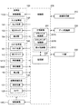
- FIG. 4A to 4E show configuration examples of the processing system of the ophthalmologic apparatus according to the embodiment.
- FIG. 4A the same parts as in FIG. 1 and FIG.
- FIG. 4B to FIG. 4E the same parts as in FIG.
- Control unit As shown in FIG. 4A, the processing system of the ophthalmologic apparatus according to the embodiment is configured around the control unit 200.
- the control unit 200 controls each unit of the ophthalmologic apparatus.
- Control unit 200 includes a main control unit 201 and a storage unit 202.
- the function of the main control unit 201 is realized by, for example, a microprocessor.
- a computer program for controlling the ophthalmologic apparatus is stored in advance.
- the computer program includes various light source control programs, light scanner control programs, various detector control programs, image forming programs, data processing programs, user interface programs, and the like.
- the main control unit 201 operates in accordance with such a computer program, whereby the control unit 200 executes control processing.
- control for the objective lens system 110 there is control for a moving mechanism 110D for moving the objective lens system 110 along the optical axis O.
- the moving mechanism 110D is provided with an actuator that generates a driving force for moving the moving mechanism 110D, and a transmission mechanism that transmits the driving force.
- the actuator is constituted by, for example, a pulse motor.
- the transmission mechanism is configured by, for example, a combination of gears, a rack and pinion, and the like.
- the main control unit 201 controls the moving mechanism 110D by sending a control signal to the actuator.
- the control of the SLO optical system 130 includes control of the SLO light source 131, control of the optical scanner 136, control of the detector 135, and the like.
- the control of the SLO light source 131 includes turning on and off the light source, adjusting the light amount, adjusting the aperture, and the like.
- the control of the light scanner 136 includes control of a scan position and a scan range by the light scanner 136X and control of a scan position and a scan range by the light scanner 136Y.
- the control of the detector 135 includes exposure adjustment of the detection element, gain adjustment, detection rate adjustment, and the like.
- the control of the OCT optical system 140 includes control of the OCT light source 151, control of the optical scanner 142, control of the moving mechanism 141D and the moving mechanism 154D, and control of the detector 155.
- the control of the OCT light source 151 includes turning on and off the light source, adjusting the light amount, adjusting the aperture, and the like.
- the control of the light scanner 142 includes control of a scan position and a scan range by the light scanner 142X, control of a scan position and a scan range by the light scanner 142Y, and the like.
- the moving mechanism 141 D moves the focusing lens 141 along the optical path of the OCT optical system 140.
- the moving mechanism 141D is provided with an actuator that generates a driving force for moving the moving mechanism, and a transmission mechanism that transmits the driving force.
- the actuator is constituted by, for example, a pulse motor.
- the transmission mechanism is configured by, for example, a combination of gears, a rack and pinion, and the like.
- the main control unit 201 controls the moving mechanism 141D by sending a control signal to the actuator.
- the moving mechanism 154D moves the prism 154 in the direction along the incident light path and the outgoing light path of the reference light LR.
- the moving mechanism 154D is provided with an actuator that generates a driving force for moving the moving mechanism, and a transmission mechanism that transmits the driving force.
- the actuator is constituted by, for example, a pulse motor.
- the transmission mechanism is configured by, for example, a combination of gears, a rack and pinion, and the like.
- the main control unit 201 controls the moving mechanism 154D by sending a control signal to the actuator.
- the control of the detector 155 includes exposure adjustment of the detection element, gain adjustment, detection rate adjustment, and the like.
- Control of the anterior eye imaging system 120 includes control of the anterior eye illumination light source 121, control of the anterior eye imaging camera 123, and the like.
- the control of the anterior ocular segment illumination light source 121 includes turning on and off the light source, adjusting the light amount, and adjusting the aperture.
- the control of the anterior-eye imaging camera 123 includes exposure adjustment, gain adjustment, imaging rate adjustment, and the like of the imaging element.
- Control of the optical system 100 includes control of a moving mechanism 100D that moves the optical system 100 (including the dichroic mirrors DM1A and DM1B and the anterior segment imaging system 120) in the X direction, the Y direction, and the Z direction.
- the moving mechanism 100D is provided with an actuator that generates a driving force for moving the moving mechanism, and a transmission mechanism that transmits the driving force.
- the actuator is constituted by, for example, a pulse motor.
- the transmission mechanism is configured by, for example, a combination of gears, a rack and pinion, and the like.
- the main control unit 201 controls the moving mechanism 100D by sending a control signal to the actuator.
- the main control unit 201 includes an alignment control unit 201A, a tracking control unit 201B, and a display control unit 201C.
- the alignment control unit 201A controls the execution of alignment for aligning the optical system 100 with the eye E.
- the alignment control unit 201A controls the moving mechanisms 100D and 110D based on the anterior segment image of the eye E obtained by the anterior segment photographing system 120.
- the alignment control unit 201A specifies, for example, a characteristic site in the anterior segment image of the subject eye E obtained by the anterior segment imaging system 120, and the amount of deviation between the position of the identified characteristic site and a predetermined target position.
- the amount of movement of the optical system 100 or the like is determined so that The alignment control unit 201A aligns the optical system 100 with the eye E by controlling the moving mechanism 100D based on the calculated movement amount (X and Y directions).
- the target position may be a predetermined position, or may be a position in the anterior segment image specified using the UI unit 230.
- the alignment control unit 201A specifies, for example, the in-focus state (the degree of blurring) of the anterior-eye image of the subject eye E obtained by the anterior-eye imaging system 120, and the specified in-focus state is a desired in-focus state It is possible to obtain the amount of movement of the objective lens system 110 in the Z direction so that The alignment control unit 201A performs alignment of the optical system 100 and the objective lens system 110 with respect to the eye E by controlling the moving mechanisms 100D and 110D based on the calculated movement amount (Z direction). Note that the anterior segment is photographed from two different directions using two or more cameras, and the in-focus state is specified three-dimensionally from the two or more images provided with parallax, and the specified in-focus state is desired. The amount of movement of the objective lens system 110 in the Z direction may be determined so as to be in focus.
- the alignment control unit 201A may perform alignment (Z direction) of the objective lens system 110 with respect to the eye E by controlling the moving mechanism 110D based on the SLO image obtained by the SLO optical system 130.
- the alignment control unit 201A specifies the in-focus state (the degree of blurring) of the acquired SLO image, and the objective lens system 110 in the Z direction is set such that the specified in-focus state becomes the desired in-focus state. Find the amount of movement.
- the alignment control unit 201A controls the moving mechanism 110D based on the obtained movement amount.
- the tracking control unit 201B performs tracking control on the basis of the SLO image of the eye to be examined E obtained by the SLO optical system 130.
- the tracking control unit 201B uses the base image, which is an SLO image of the fundus oculi Ef of the eye to be examined E obtained in advance, as a reference, and the positional deviation amount of the target image, which is an SLO image of the fundus oculi Ef obtained after acquisition It is possible to obtain (including the misregistration direction) and to perform tracking control based on the obtained misregistration amount.
- the target image is an image acquired by scanning a scan area narrower than the scan area when acquiring the base image.
- the tracking control unit 201B can perform tracking control based on the positional deviation amount between the partial image corresponding to the target image in the base image and the target image.
- the positional deviation amount of the target image with respect to the partial image is obtained by phase limited correlation processing.
- the tracking control unit 201B can control the moving mechanism 100D and the optical scanner 136 based on the determined positional deviation amount.
- the tracking control unit 201B can control the optical scanner 142 based on the calculated positional deviation amount. For example, the tracking control unit 201B corrects the scan position of the optical scanner 142 based on the calculated positional displacement amount.
- the display control unit 201C causes the UI unit 230 described later to display various information.
- the information displayed on the UI unit 230 includes information generated by the control unit 200, an image formed by the image forming unit 210, information after data processing by the data processing unit 220, and the like.
- the image forming unit 210 forms various images (image data). Various images (image data) formed by the image forming unit 210 are stored, for example, in the storage unit 202.
- the image forming unit 210 includes an SLO image forming unit 210A and an OCT image forming unit 210B.
- the SLO image forming unit 210A forms the image data of the SLO image based on the detection signal input from the detector 135 and the pixel position signal input from the control unit 200.
- the SLO image forming unit 210A includes a base image forming unit 211A and a target image forming unit 212A.
- the base image forming unit 211A forms a base image based on the scan result of the scan area corresponding to the base image.
- the target image forming unit 212A forms a target image based on the scan result of the scan area corresponding to the target image.
- the OCT image forming unit 210B forms image data of an OCT image (tomographic image of the fundus oculi Ef) based on the detection signal input from the detector 155 and the pixel position signal input from the control unit 200.
- the image forming unit 210 can form an anterior segment image based on the detection result of the reflected light from the anterior segment of the eye E to be examined by the imaging element of the anterior segment photographing camera 123.
- the data processing unit 220 executes various data processing.
- An example of data processing is processing on image data formed by the image forming unit 210 or another device. Examples of this process include various image processes, analysis processes on images, and diagnosis support processes such as image evaluation based on image data.
- the data processing unit 220 determines the amount of positional deviation between the partial image corresponding to the target image and the target image in the base image acquired in advance, and controls the information corresponding to the calculated amount of positional deviation It outputs to 200 (main control unit 201).
- the amount of positional deviation is the amount of rotational movement of the sub-pixel level between the partial image and the target image in the direction of rotation of less than one pixel (rotational direction about the Z axis), its rotational movement direction, partial image and target It includes the amount of translation in the XY plane of the subpixel level between the image and the image, the translation direction thereof, and the like.
- the data processing unit 220 calculates the rotational movement amount and rotational movement direction between the partial image and the target image at the sub-pixel level, and the partial image based on the calculated rotational movement amount and rotational movement direction Perform rotational alignment between the image and the target image. Thereafter, the data processing unit 220 calculates the amount of translation and the direction of translation between the aligned partial image and the target image at the subpixel level.
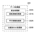
- such a data processing unit 220 includes a displacement processing unit 220A and an alignment processing unit 220B.
- the displacement processing unit 220A determines the displacement (including the amount of misalignment and the direction of misalignment) of the target image with respect to the partial image based on the partial image and the target image in the base image as described above.
- the alignment processing unit 220B aligns the partial image with the target image.
- the displacement processing unit 220A includes a rotational movement processing unit 221A and a parallel movement processing unit 222A.
- the rotational movement processing unit 221A calculates the rotational movement amount and rotational movement direction between the partial image and the target image.
- the rotational movement processing unit 221A can calculate the rotational movement amount and rotational movement direction between the partial image and the target image by performing the phase limited correlation process on the partial image and the target image.
- phase limited correlation processing is similar to the processing disclosed in Japanese Patent Laid-Open No. 2015-043898 (Patent Document 2).
- phase limited correlation function is used in the phase limited correlation processing according to the embodiment.
- a partial image corresponding to a target image in the base image may be referred to as a “base image”.
- the image size is N 1 ⁇ N 2 (N 1 , N 2 is a positive integer) is a partial image (base image) to f (n 1, n 2), the target image g (n 1, n 2) I assume.
- n 1 ⁇ M 1 ,..., M 1 on a discrete space
- N 1 2M 1 +1 (M 1 is a positive integer)
- a two-dimensional discrete of f (n 1 , n 2 ) Assuming that the calculation result of the discrete Fourier transformation (hereinafter referred to as DFT) is F (k 1 , k 2 ), F (k 1 , k 2 ) is expressed as equation (1).
- DFT discrete Fourier transformation
- a F (k 1 , k 2 ) is the amplitude component of f (n 1 , n 2 ), and e j ⁇ F (k 1 , k 2 ) is the phase component of f (n 1 , n 2 ) is there.
- a G (k 1 , k 2 ) is an amplitude component of g (n 1 , n 2 ), and ej ⁇ G (k 1 , k 2 ) is a phase component of g (n 1 , n 2 ) is there.
- phase limited combination function used for the phase limited combination processing is defined as equation (3) using equations (1) and (2).
- phase limited correlation function can be expressed by equation (4) by applying two-dimensional inverse discrete Fourier transformation (hereinafter referred to as IDFT) to the phase limited composite function of equation (3). expressed.
- the 2-dimensional images s c of the continuous space is defined (x 1, x 2), by a minute amount of movement [delta] 1 in x 1 direction and the image obtained by shifting the x 2 direction by a minute amount of movement [delta] 2 is , S c (x 1 - ⁇ 1 , x 2 - ⁇ 2 ).
- a two-dimensional image f (n 1 , n 2 ) on a discrete space sampled at a sampling interval T 1 is defined as equation (5).
- a two-dimensional image g (n 1 , n 2 ) on a discrete space sampled at a sampling interval T 2 is defined as equation (6).
- n 1 -M 1, ⁇ , a M 1
- n 2 -M 2 , ⁇ , a M 2.
- the phase-only correlation function with respect to the two-dimensional images f (n 1 , n 2 ) and g (n 1 , n 2 ) on the discrete space is represented by a general form such as equation (7).
- the rotational movement processing unit 221A includes a first conversion processing unit 301, a logarithmic conversion unit 302, a polar coordinate conversion unit 303, a second conversion processing unit 304, and a first phase limit combining unit 305. , And the first inverse transformation processing unit 306.
- the first conversion processing unit 301 performs two-dimensional DFT processing on a partial image (base image). Further, the first conversion processing unit 301 performs two-dimensional DFT processing on the target image.
- the two-dimensional DFT process performed by the first transformation processing unit 301 includes a two-dimensional DFT and a known shift process for shifting a quadrant with respect to the calculation result of the two-dimensional DFT. Hereinafter, this shift process may be referred to as “shift”.
- the two-dimensional DFT performed by the first transformation processing unit 301 may be a two-dimensional FFT.
- the logarithmic conversion unit 302 performs logarithmic conversion on the calculation result by the first conversion processing unit 301 on the partial image (base image). Further, the logarithmic conversion unit 302 performs logarithmic conversion on the calculation result by the first conversion processing unit 301 for the target image.
- the logarithmic conversion by the logarithmic conversion unit 302 has an effect of compressing an amplitude spectrum which tends to be concentrated in the low frequency region of the spatial frequency in the natural image.
- the polar coordinate conversion unit 303 performs polar coordinate conversion on the calculation result by the logarithmic conversion unit 302 for the partial image (base image).
- the polar coordinate conversion unit 303 performs polar coordinate conversion on the calculation result of the logarithmic conversion unit 302 for the target image.
- the polar coordinate conversion unit 303 performs polar coordinate conversion on the calculation result by the first conversion processing unit 301 for the partial image (base image), and performs first conversion for the target image.
- Polar coordinate conversion is performed on the calculation result by the conversion processing unit 301.
- Polar conversion by polar coordinate transformation unit 303 is a process of converting the movement amount of the rotational direction to the amount of movement of the parallel direction (n 1 direction and n 2 direction) in the formula (1) to (7).
- the second conversion processing unit 304 performs a two-dimensional DFT process (two-dimensional DFT + shift) on the calculation result by the polar coordinate conversion unit 303 for the partial image (base image), as shown in equation (1).
- the processing result of the second conversion processing unit 304 for the partial image (base image) is, for example, stored in the storage unit 202 as base POC data normalized with the amplitude component prior to the arithmetic processing by the first phase-limited combining unit 305. Pre-stored.
- the second conversion processing unit 304 performs two-dimensional DFT processing (two-dimensional DFT + shift) on the calculation result of the polar coordinate conversion unit 303 for the target image, as shown in equation (2).
- the two-dimensional DFT performed by the second transformation processing unit 304 may also be a two-dimensional FFT.
- the first phase-limited combining unit 305 generates, as shown in equation (3), base POC data (first data) obtained in advance for the partial image (base image) and the second conversion processing unit 304 for the target image.
- a phase limited combining process is performed to combine target POC data (second data) normalized with the amplitude component based on the calculation result.
- the first inverse transform processing unit 306 performs a two-dimensional IDFT process on the calculation result by the first phase only synthesis unit 305.
- the two-dimensional IDFT process performed by the first inverse transformation processing unit 306 includes a two-dimensional IDFT and a known shift process for shifting a quadrant with respect to the calculation result of the two-dimensional IDFT.
- the two-dimensional IDFT may be calculated by two-dimensional Inverse Fast Fourier Transformation (hereinafter, IFFT).
- the rotational movement processing unit 221A calculates the rotational movement amount and the rotational movement direction based on the calculation result by the first inverse conversion processing unit 306. Specifically, the rotational movement processing unit 221A determines the rotational movement amount and rotational movement direction at the pixel level by specifying the peak position based on the calculation result by the first inverse transformation processing unit 306. After that, the rotational movement processing unit 221A determines the sub-pixel by specifying the pixel position at which the correlation value of the phase only correlation function shown in equation (7) is maximum in the vicinity of the peak position specified at the pixel level. Determine the rotational movement amount and rotational movement direction by level.
- the rotational movement processing unit 221A may not calculate the rotational movement amount and the rotational movement direction by the phase limited correlation process, and may calculate the rotational movement amount and the rotational movement direction by a known method.
- the parallel movement processor 222A calculates the amount of parallel movement and the direction of parallel movement between the partial image (base image) that has been aligned by the alignment processor 220B described later and the target image.
- the parallel movement processing unit 222A performs the phase limited correlation processing on the partial image and the target image that have been aligned by the registration processing unit 220B, thereby to translate the parallel movement amount and parallel movement between the partial image and the target image. Calculate the direction.
- phase limited correlation processing is similar to the processing disclosed in Japanese Patent Laid-Open No. 2015-043898.
- the translation processing unit 222A determines the translation amount and the translation direction between the partial image and the target image that have been aligned by the alignment processing unit 220B. Specifically, the parallel movement processing unit 222A performs phase-only correlation processing on the partial image and the target image that have been aligned by the alignment processing unit 220B, thereby achieving a parallel between the partial image and the target image. The movement amount and the parallel movement direction are calculated.
- the translation processing unit 222A includes a third conversion processing unit 311, a second phase-only combining unit 312, and a second inverse conversion processing unit 313.
- the third transform processing unit 311 performs a two-dimensional DFT process (two-dimensional DFT + shift) on the partial image (base image), as shown in equation (1).
- the processing result by the third conversion processing unit 311 for the partial image is, for example, the storage unit 202 as base POC data (third data) normalized by the amplitude component prior to the arithmetic processing by the second phase-limited combining unit 312. In advance.
- the third transform processing unit 311 performs two-dimensional DFT processing (two-dimensional DFT + shift) on the target image, as shown in Expression (2).
- the two-dimensional DFT performed by the third transformation processing unit 311 may be a two-dimensional FFT.
- the second phase-limited combining unit 312 generates base POC data (third data) obtained in advance for the partial image (base image) and the third conversion processing unit 311 for the target image, as shown in equation (3). Based on the calculation result, phase limited combining processing is performed to combine target POC data (fourth data) normalized with the amplitude component.
- the second inverse transform processing unit 313 performs a two-dimensional IDFT process (two-dimensional IDFT + shift) on the calculation result by the second phase only synthesis unit 312.
- the two-dimensional IDFT performed by the second inverse transform processor 313 may be a two-dimensional IFFT.
- the parallel movement processing unit 222A calculates the amount of parallel movement and the direction of parallel movement based on the calculation result by the second inverse conversion processing unit 313. Specifically, the translation processing unit 222A determines the amount of translation and the direction of translation at the pixel level by specifying the peak position based on the calculation result by the second inverse transform processing unit 313. After that, the parallel shift processing unit 222A determines the sub-pixel by specifying the pixel position at which the correlation value of the phase-only correlation function shown in Equation (7) is maximum in the vicinity of the peak position specified at the pixel level. Find the translation amount and translation direction at the level.
- the alignment processing unit 220B aligns the rotational direction between the partial image and the target image based on the rotational movement amount and the rotational movement direction obtained by the rotational movement processing unit 221A. Specifically, based on the rotational movement amount and the rotational movement direction calculated by the rotational movement processing unit 221A, the alignment processing unit 220B aligns the target image in the rotational direction based on the partial image. Note that even if the alignment processing unit 220B performs alignment of the partial image in the rotational direction based on the target image based on the rotational movement amount and the rotational movement direction calculated by the rotational movement processing unit 221A. Good.
- a UI (User Interface) unit 230 has a function to exchange information between the user and the ophthalmologic apparatus.
- the UI unit 230 includes a display device and an operation device (input device).
- the display device may include a display unit, and may include other display devices.
- the operating device includes various hardware keys and / or software keys.
- the control unit 200 can receive an operation content on the operation device and can output a control signal corresponding to the operation content to each unit. It is possible to integrally configure at least a portion of the operation device and at least a portion of the display device.
- the touch panel display is one example.
- the light (SLO light) emitted from the SLO light source 131 and transmitted through the beam splitter BS2 is an example of the “first light” according to the embodiment.
- the light scanner 136 is an example of the “first light scanner” according to the embodiment.
- the subject eye E is an example of the "target eye” according to the embodiment.
- the SLO optical system 130 is an example of the “SLO system” according to the embodiment.
- the measurement light LS is an example of the “second light” according to the embodiment.
- the light scanner 142 is an example of the “second light scanner” according to the embodiment.
- the OCT optical system 140 is an example of the “projection system” or the “OCT system” according to the embodiment.
- the base image is an example of the “first image” according to the embodiment.
- the base image forming unit 211A is an example of the “first image forming unit” according to the embodiment.
- the target image is an example of the “second image” according to the embodiment.
- the target image forming unit 212A is an example of the “second image forming unit” according to the embodiment.
- the OCT image forming unit 210B is an example of the “third image forming unit” according to the embodiment.
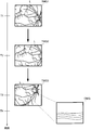
- FIG. 5 is an explanatory view of an operation example of the ophthalmologic apparatus according to the embodiment.
- FIG. 5 illustrates a partial image of a base image according to the embodiment and an explanatory view of a target image.
- the target image of the fundus oculi Ef (TI1) is scanned by scanning a scan area narrower than the scan area when acquiring the base image.
- TI2, ...) are sequentially acquired. Each time a target image (TI1, TI2, ...) is acquired, the positional deviation amount between the target image and a partial image (BI1, BI2, ...) in the base image corresponding to the target image is obtained.
- the rotational movement processing unit 221A obtains ⁇ 1 representing the rotational movement amount and rotational direction of the target image TI1 with respect to the partial image BI1.
- the parallel movement processing unit 222A obtains ⁇ x1 and ⁇ y1 representing the parallel movement amount and the parallel movement direction of the target image TI1 with respect to the partial image BI1.
- the rotational movement processing unit 221A obtains ⁇ 2 representing the rotational movement amount and rotational direction of the target image TI2 with respect to the partial image BI2.
- the parallel movement processing unit 222A also calculates ⁇ x2 and ⁇ y2 representing the parallel movement amount and the parallel movement direction of the target image TI2 with respect to the partial image BI2.
- the tracking control unit 201B corrects the scan position of the optical scanner 142 based on the positional shift amount ( ⁇ x1, ⁇ y1, ⁇ 1) of the target image TI1 with respect to the partial image BI1. Subsequently, when the target image TI2 is acquired, the tracking control unit 201B corrects the scan position of the optical scanner 142 based on the positional shift amount ( ⁇ x2, ⁇ y2, ⁇ 2) of the target image TI2 with respect to the partial image BI2.
- the main control unit 201 performs SLO optical system 130 (optical scanner 136) so as to repeatedly scan while changing the position of the scan area for acquiring the target image in the eye E to be examined. And causes the target image forming unit 212A to form a target image each time scanning of the scan area is completed, and causes the displacement processing unit 220A to calculate the amount of displacement (displacement), based on the calculated amount of displacement.
- the optical scanner 142 is controlled.
- the main control unit 201 tilt control unit 201B
- FIG. 6 schematically shows an example of the correction of the scan position according to the embodiment.
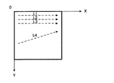
- FIG. 6 schematically shows a scan area in the case where a line scan along the X direction is sequentially moved in the Y direction by the optical scanner 142 in the OCT optical system 140.
- the tracking control unit 201B determines that the scan end position is (xe, ye). And the direction of the line scan L4 is rotated by "-.DELTA..theta.”. Then, the tracking control unit 201B corrects the scan position so that the scan end position of the line scan L4 is (xe + h1 ( ⁇ x), ye + h2 ( ⁇ y)).
- h1 and h2 are predetermined functions. For example, assuming that k is an arbitrary coefficient, the tracking control unit 201B can correct the scan position in the x direction by ( ⁇ k ⁇ ⁇ x) and correct in the y direction by ( ⁇ k ⁇ ⁇ y). .
- FIG. 7 is an explanatory view of tracking control in the ophthalmologic apparatus according to the embodiment.
- FIG. 7 schematically shows the target image and the OCT image at times T1, T2 and T3 while scanning the scan line L. In each target image, the position of the scan line L by the OCT optical system 140 is schematically illustrated.
- FIG. 7 schematically shows the case where the target image is moved in parallel with respect to the base image, but the same applies to the case where the target image is moved in rotation with respect to the base image.
- the target image TMG1 is acquired, and the OCT optical system 140 starts scanning of the scan line L.
- the displacement processing unit 220A determines the amount of positional deviation, and the tracking control unit 201B Then, the scan position of the optical scanner 142 is corrected based on the determined positional deviation amount. Thereby, at time T2, the scan is continued at the position of the scan line L in the target image TMG2.
- the displacement processing unit 220A determines the amount of positional deviation as described above, and performs tracking control
- the unit 201B corrects the scan position of the optical scanner 142 based on the calculated positional shift amount. Thereby, at time T3, the scan is continued at the position of the scan line L in the target image TMG2.
- the scan position by the light scanner 142 follows the eye movement between times T1 and T3.
- an OCT image OMG is formed based on the scan result on the scan line L (FIG. 7).
- the SLO optical system 130 can be used. Even when used, the target image can be acquired in a short time. Thereby, it is possible to follow the eye movement during acquisition of the SLO image, and to perform high-speed tracking control.
- the positional deviation amount of the target image with respect to the partial image of the base image is obtained by the phase limited correlation processing, highly accurate tracking control can be performed. Furthermore, by performing a scan for acquiring the next target image while calculating the positional deviation amount, it is possible to further increase the speed.
- the position of the scan area for acquiring the target image is changed such that the position of the partial image in the base image is changed.
- the position of the scan area in the fundus oculi Ef may be determined such that the position of the partial image in the base image is a fixed position. In this case, the process of specifying the position of the partial image in the base image is simplified.
- the position of the scan area on the fundus oculi Ef for acquiring the target image may be changed so that the base image is covered by a plurality of partial images.
- tracking control can be performed based on the form of the fundus oculi Ef drawn in a wide range in the base image, it is possible to improve the tracking accuracy.
- the data processing unit 220 includes an analysis unit that specifies a characteristic portion of the fundus oculi Ef, and the size of a scan area including a region corresponding to the characteristic portion specified by the analysis unit is larger than other scan regions. It may be. This makes it possible to improve the tracking accuracy.
- the size of the scan area for acquiring the target image may be changed at the next scan. For example, when the positional deviation amount between the target image and the partial image is equal to or larger than a predetermined threshold, the size of the scan area may be enlarged when acquiring the next target image.
- At least a part of a scan area for acquiring a target image may overlap with a scan area for acquiring another target image.
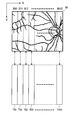
- a target image such that a partial image corresponding to the target image is an image obtained by dividing the base image BI in the X direction which is the scanning direction by the optical scanner 136 (optical scanner 142) It is assumed that the position of the scan area of is sequentially moved in the X direction.
- FIG. 8 is an explanatory view of a partial image according to the embodiment.
- FIG. 8 shows partial images BI0 to BI15 obtained by dividing the base image BI into 16 at regular intervals in the X direction. That is, the sizes of the partial images BI0 to BI15 in the Y direction are the same, and the sizes in the X direction are the same.
- the main control unit 201 controls the SLO optical system 130 so as to sequentially scan the scan region set to obtain the target image shown in FIG. 8, and sequentially transmits the target images TI0 to TI15 to the target image forming unit 212A.
- Each of the target images TI0 to TI15 is an image in which the size in the Y direction is the same as the size in the Y direction of the base image BI and the size in the X direction is one sixteenth of the size in the X direction of the base image BI. is there.
- the main control unit 201 causes the displacement processing unit 220A to calculate the displacement amount with respect to the partial image corresponding to the target image each time the target image is acquired, and controls the optical scanner 142 based on the calculated displacement amount. Do.
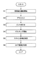
- FIG. 9 is a flowchart showing an example of the operation of the ophthalmologic apparatus according to the embodiment.
- the objective lens unit 110A for the wide-angle shooting mode is set on the optical axis O.
- the main control unit 201 continuously illuminates the fundus oculi Ef with illumination light from the anterior eye illumination light source 121, and starts acquisition of an anterior eye image by the anterior eye photographing camera 123.
- the alignment control unit 201A performs alignment of the optical system 100 and the objective lens system 110 with respect to the eye E by controlling the moving mechanism 100D based on the anterior eye image acquired in step S1 (X direction and Y direction). For example, the alignment control unit 201A controls the moving mechanism 100D such that the position of the characteristic portion (the position of the area corresponding to the pupil) in the anterior segment image specified by the data processing unit 220 is a predetermined position.
- the main control unit 201 moves the scan position of each of the optical scanners 136 and 142 to a predetermined initial position.
- the main control unit 201 turns on the SLO light source 131 and controls the light scanner 136 to start scanning of the fundus oculi Ef of the eye E with light from the SLO light source 131.
- the SLO image forming unit 210A forms an SLO image of the fundus oculi Ef based on the detection result of the fundus oculi reflected light by the detector 135.
- the alignment control unit 201A performs alignment of the focus direction (Z direction) of the retina from the anterior segment image obtained in step S1 or the SLO image obtained in step S3. This enables fine adjustment of the position of the objective lens system 110 in the direction of the optical axis O.
- the tracking control unit 201B starts tracking control.
- the tracking control unit 201B can execute tracking control on the SLO image and tracking control on the OCT image.
- the main control unit 201 causes the display unit of the UI unit 230 to display the SLO image in real time.
- the user uses the operation unit of the UI unit 230 to set a scan area on the SLO image.
- the scan area to be set may be a one-dimensional area or a two-dimensional area.
- the main control unit 201 controls the OCT optical system 140 to control the optical scanner 142 based on the scan area set in step S5, thereby performing OCT measurement of the fundus oculi Ef.
- the OCT image forming unit 210B forms a tomogram of the fundus oculi Ef based on the obtained detection signal.
- the data processing unit 220 forms a three-dimensional image of the fundus oculi Ef based on the plurality of tomographic images formed by the OCT image forming unit 210B. This is the end of the operation example (end).
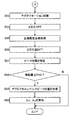
- FIG. 10 is a flowchart of an example of processing for tracking control according to the embodiment. For example, when the eye to be examined E is changed or the imaging mode is changed, the process shown in FIG. 10 is performed.
- the main control unit 201 performs predetermined initialization processing.
- the initialization process includes securing of resources, setting of a scan area for acquiring a base image and a target image, and initialization of the displacement processing unit 220A.
- the main control unit 201 causes the displacement processing unit 220A to perform base image processing for performing phase limited correlation processing on a partial region in the base image corresponding to the target image. Details of the base image processing will be described later.
- the main control unit 201 causes the displacement processing unit 220A to perform target image processing for performing phase-only correlation processing on the sequentially input target images.
- target image processing processing for tracking control based on a partial image corresponding to the target image and the target image is performed. Details of the target image processing will be described later.
- the main control unit 201 determines whether there is a next partial image.
- the base image is divided into 16 partial image areas, and target image processing is sequentially performed on each partial image area.
- step S14 When it is determined that the next partial image is present (S14: Y), the operation of the ophthalmologic apparatus proceeds to step S13. When it is determined that there is no next partial image (S14: N), the operation of the ophthalmologic apparatus proceeds to step S15.
- step S14 When it is determined in step S14 that the next partial image is not present (S14: N), the main control unit 201 determines whether to end the imaging. When it is determined that the imaging is not finished (S15: N), the operation of the ophthalmologic apparatus proceeds to step S12. That is, when target image processing is performed on target images (TI0 to TI15) corresponding to all partial images (BI0 to BI15), target images (TI0) to target images corresponding to the first partial image (BI0) are again generated. Processing is performed sequentially. When it is determined that the photographing is ended (S15: Y), the processing for tracking control is ended (END).
- step S12 Next, the base image processing of step S12 will be described.
- FIG. 11 shows an example of the flow of base image processing according to the embodiment.
- Base image processing shown in FIG. 11 is performed for each partial image of the base image.
- the rotational movement processing unit 221A performs an apodization process on a partial image (base image) corresponding to the target image.
- the apodization process is a process of reducing the amplitude of the main lobe to some extent and reducing the amplitude of the side lobe by multiplying the apodization function to increase the dynamic range.
- the apodization function there are known Hanning windows, window functions such as Gaussian windows and rectangular windows.
- the apodization process is performed by, for example, an apodization processing unit (not shown) in the first conversion processing unit 301 or the rotation movement processing unit 221A.
- the first conversion processing unit 301 performs a two-dimensional DFT on the result of the apodization processing on the partial image in step S21.
- the logarithmic conversion unit 302 performs logarithmic conversion on the processing result of the two-dimensional DFT in step S22.
- Logarithmic conversion is expressed as Expression (8), where Re is a real component of a processing result of a two-dimensional DFT, Im is an imaginary component, and Am is a logarithmic conversion result. This compresses the amplitude spectrum which tends to be concentrated in the low frequency region of the spatial frequency in the natural image.
- step S24 Log-Polar conversion
- the polar coordinate conversion unit 303 performs Log-Polar conversion on the processing result of logarithmic conversion in step S23. Thereby, the radial direction is converted into the X direction, and the declination direction is converted into the Y direction.
- the second conversion processing unit 304 performs a two-dimensional DFT on the processing result of the Log-Polar conversion in step S24.
- the rotational movement processing unit 221A normalizes the amplitude component on the basis of the processing result of the two-dimensional DFT in step S25, and stores it in the storage unit 202 as first base POC data based on the processing result of the two-dimensional DFT.
- the first base POC data stored in the storage unit 202 is used to calculate the correlation value of the phase limited correlation function for calculating the rotational movement amount and the rotational direction.
- step S27 apodization process
- the third transformation processing unit 311 performs a two-dimensional DFT on the real component of the result of the apodization processing on the partial image.
- the parallel shift processing unit 222A normalizes the amplitude component based on the processing result of the two-dimensional DFT in step S28, and stores the second base POC data based on the processing result of the two-dimensional DFT in the storage unit 202.
- the second base POC data stored in the storage unit 202 is used to calculate the correlation value of the phase limited correlation function for calculating the amount of parallel movement and the direction of parallel movement. This is the end of the series of base image processing (end).
- step S13 the target image processing of step S13 will be described.
- the target image processing includes processing for generating target POC data for a target image, processing for calculating rotational movement amount and rotational movement direction, alignment processing, and calculation processing for parallel movement amount and parallel movement direction.
- the rotational movement processing unit 221A performs an apodization process on the target image. This process is the same as step S21, and is performed by an apodization processing unit (not shown) in the first conversion processing unit 301 or the rotational movement processing unit 221A.
- the first conversion processing unit 301 performs a two-dimensional DFT on the result of the apodization processing on the partial image in step S41.
- step S43 Logarithmic conversion
- the logarithmic conversion unit 302 performs logarithmic conversion on the processing result of the two-dimensional DFT in step S42. This logarithmic conversion is similar to step S23.
- step S44 Log-Polar conversion
- the polar coordinate conversion unit 303 performs Log-Polar conversion on the processing result of logarithmic conversion in step S43. This Log-Polar conversion is similar to step S24.
- the second conversion processing unit 304 performs a two-dimensional DFT on the processing result of the Log-Polar conversion in step S44.
- the first phase-limited combining unit 305 combines the first base POC data stored in the storage unit 202 in step S26 and the target POC data obtained by normalizing the processing result of the two-dimensional DFT in step S45 with the amplitude component. Using this, phase limited synthesis processing is performed according to the equation shown in equation (3).
- the first base POC data is base POC data generated for a partial image corresponding to the target image.
- the first inverse transform processing unit 306 applies a two-dimensional IDFT to the processing result of the phase only combining processing in step S46 according to the equation shown in equation (4).
- the rotational movement processing unit 221A determines whether the rotation angle (absolute value) corresponding to the declination is equal to or less than the first threshold TH1. When it is determined that the rotation angle is not less than or equal to the first threshold TH1 (S49: N), the rotation movement processing unit 221A determines that an error occurs, and ends the series of processing (END). On the other hand, when it is determined that the rotation angle is equal to or less than the first threshold TH1 (S49: Y), the processing of the rotation movement processing unit 221A proceeds to step S50.
- the rotation movement processing unit 221A calculates the correlation value of the phase only correlation function at the sub-pixel level according to Equation (7). . Specifically, as disclosed in Japanese Patent Laid-Open No. 2015-043898, the rotational movement processing unit 221A obtains a plurality of correlation values of the phase limited correlation function shown in Expression (7) at the sub-pixel level, and By specifying the position, a high argument (coordinate in the y direction) of the correlation value is specified.
- the rotational movement processing unit 221 ⁇ / b> A acquires an address corresponding to the identified peak value, and stores the address in the storage unit 202.
- the rotational movement processing unit 221A calculates the rotational movement amount ⁇ corresponding to the peak position specified at the sub-pixel level.
- the rotational movement direction is specified by the sign of ⁇ .
- the parallel movement processing unit 222A calculates the parallel movement amount and the parallel movement direction. That is, the translation processing unit 222A performs an apodization process on the target image on which the alignment has been performed in step S52. This process is performed by, for example, an apodization processing unit (not shown) in the third conversion processing unit 311 or the parallel movement processing unit 222A.
- the third conversion processing unit 311 performs a two-dimensional DFT on the result of the apodization processing on the target image in step S53.
- the second phase-limited combining unit 312 combines the second base POC data stored in the storage unit 202 in step S29 and target POC data obtained by normalizing the processing result of the two-dimensional DFT in step S54 with the amplitude component. Using this, phase limited synthesis processing is performed according to the equation shown in equation (3).
- the second inverse transform processing unit 313 applies a two-dimensional IDFT to the processing result of the phase only combining processing according to the equation shown in equation (4).
- step S57 Identify the peak position
- the parallel shift processing unit 222A obtains the peak value of the processing result in step S59, acquires the address of the peak position corresponding to the peak value, and stores the address in the storage unit 202.
- the parallel movement processing unit 222A Based on the address of the peak position stored in the storage unit 202, the parallel movement processing unit 222A has, for example, the amount of movement (absolute value) in the X direction and the amount of movement (absolute value) in the Y direction equal to or less than the second threshold TH2. It is determined whether or not it is. When it is determined that the amount of movement in the X direction and the amount of movement in the Y direction are not less than or equal to the second threshold TH2 (S58: N), the parallel movement processor 222A determines that there is an error and ends the series of processing ( End). On the other hand, when it is determined that the amount of movement in the X direction and the amount of movement in the Y direction are less than or equal to the second threshold TH2 (S58: Y), the processing of the parallel movement processor 222A proceeds to S59.
- the parallel movement processor 222A performs phase-only correlation at the sub-pixel level according to equation (7) Calculate the correlation value of the function. Specifically, as disclosed in Japanese Patent Laid-Open No. 2015-043898, the parallel shift processing unit 222A obtains a plurality of correlation values of the phase limited correlation function shown in equation (7) at the sub-pixel level, and By specifying the position, the movement amount (coordinate in the X direction and coordinate in the Y direction) of high correlation value is specified.
- the translation processing unit 222 ⁇ / b> A acquires an address corresponding to the identified peak value, and stores the address in the storage unit 202.
- the parallel movement processing unit 222A calculates the parallel movement amounts ⁇ x and ⁇ y corresponding to the peak position specified at the sub-pixel level.
- the translation direction is specified by the signs of ⁇ x and ⁇ y. This is the end of the series of target image processing (end).
- the rotational movement amount ⁇ and the rotational movement direction calculated as described above, and the parallel movement amounts ⁇ x and ⁇ y and the parallel movement direction are output to the control unit 200.
- the control unit 200 (main control unit 201) performs tracking by moving the device optical system three-dimensionally by controlling the moving mechanism 100D based on the calculated parallel movement amounts ⁇ x and ⁇ y.
- the ophthalmologic apparatus includes an SLO system (SLO optical system 130), a projection system (OCT optical system 140 or laser irradiation system), a first image forming unit (base image forming unit 211A), and a second image forming unit. It includes a unit (target image forming unit 212A), a displacement processing unit (220A), and a control unit (control unit 200, main control unit 201, tracking control unit 201B).
- the SLO system includes a first light scanner (light scanner 136) for deflecting the first light, and scans the target eye (eye E to be examined) with the first light deflected by the first light scanner.
- the projection system includes a second light scanner (light scanner 142) that deflects the second light (measurement light LS), and projects the second light deflected by the second light scanner onto the target eye.
- the first image forming unit forms a first image (base image) of the target eye based on the scan result of the first scan area using the first light scanner.
- the second image forming unit forms a second image (target image) of the target eye based on the scan result of the second scan area narrower than the first scan area using the first light scanner.
- the displacement processing unit calculates displacement (displacement amount, misregistration direction) between the partial image corresponding to the second image in the first image and the second image.
- the control unit controls the second optical scanner based on the displacement calculated by the displacement processing unit.
- the second scan area which is narrower than the first scan area for acquiring the first image is scanned to acquire the second image, Since the second light scanner of the projection system is controlled based on the displacement between the first image and the second image, the second image can be acquired in a short time even when the SLO system is used become. Thereby, it is possible to follow the eye movement during acquisition of the second image which is the SLO image, and to perform high-speed tracking control.
- control unit may correct the projection position of the second light by the projection system based on the displacement.
- the speed of tracking control can be increased by a simple control. Will be able to
- the second image is an image corresponding to one of two or more partial images obtained by dividing the first image in the first scan direction (X direction) by the SLO system. It may be.
- the narrow scan area is scanned with simple control.
- the sizes of the two or more partial images in the first scanning direction may be the same.
- control unit controls the SLO system so as to scan repeatedly while changing the position of the second scan area in the target eye, every time the scan of the second scan area is completed.
- the second image forming unit may form the second image
- the displacement processing unit may calculate the displacement
- the second optical scanner may be controlled based on the displacement.
- control unit may repeatedly execute the scan of the second scan area by the SLO system so as to scan the entire first scan area.
- the second optical scanner can be controlled based on the displacement with various regions in the first image, it is possible to improve the tracking accuracy.
- the displacement processing unit performs the phase-only correlation processing on the partial image and the second image to obtain the parallel movement amount and parallel movement between the partial image and the second image.
- the direction and / or the amount of rotational movement between the partial image and the second image and / or the direction of rotational movement may be calculated.
- the projection system projects the measurement light based on the OCT light from the OCT light source as the second light onto the target eye via the second optical scanner, and the return light and the OCT light
- Third image forming unit that includes an OCT system (OCT optical system 140) that receives interference light (LC) with reference light (LR), and forms a tomogram of the target eye based on the reception result of interference light by the OCT system (OCT image forming unit 210B) may be included.
- OCT optical system 140 that receives interference light (LC) with reference light (LR), and forms a tomogram of the target eye based on the reception result of interference light by the OCT system
- the second scan area narrower than the first scan area for acquiring the first image is scanned to acquire the second image, Since the second light scanner of the projection system is controlled based on the displacement between the first image and the second image, the second image can be acquired in a short time even when the SLO system is used become. Thereby, it is possible to follow the eye movement during acquisition of the second image which is the SLO image, and to perform high-speed tracking control.
- the projection system may include a laser irradiation system which irradiates the target eye with a laser beam output from a light source.
- the second scan area which is narrower than the first scan area for acquiring the first image is scanned to acquire the second image Since the second light scanner of the projection system is controlled based on the displacement between the first image and the second image, the second image can be acquired in a short time even when the SLO system is used. It will be. Thereby, it is possible to follow the eye movement during acquisition of the second image which is the SLO image, and to perform high-speed tracking control.
- the control method of the ophthalmologic apparatus includes the first light scanner that deflects the first light, and the SLO system that scans the target eye with the first light deflected by the first light scanner, and the second light
- a control method of an ophthalmologic apparatus comprising: a second light scanner for deflecting the light beam; and a projection system for projecting the second light deflected by the second light scanner onto the target eye,
- the And a control step of controlling the second optical scanner based on the position may comprise.
- the second scan area which is narrower than the first scan area for acquiring the first image is scanned to acquire the second image, Since the second light scanner of the projection system is controlled based on the displacement between the first image and the second image, the second image can be acquired in a short time even when the SLO system is used become. Thereby, it is possible to follow the eye movement during acquisition of the second image which is the SLO image, and to perform high-speed tracking control.
- the projection position of the second light by the projection system may be corrected based on the displacement.
- the speed of tracking control can be increased by a simple control. Will be able to
- the SLO system in the control step, is controlled to scan repeatedly while changing the position of the second scan area with respect to the target eye, and the scan of the second scan area is Every time the process is completed, a second image may be formed in the second image forming step, displacement may be calculated in the displacement processing step, and the second optical scanner may be controlled based on the displacement in the control step.
- scanning is repeated while changing the position of the second scan area, so that high-speed and highly accurate tracking control can be performed on the target eye.
- composition of optical system 100 was composition shown in Drawing 1 or Drawing 3
- composition of an optical system concerning an embodiment is not limited to this.
- the optical system according to the embodiment may include an optical system for irradiating a treatment site on the fundus with laser light, an optical system for moving a visual target in a state where the eye to be examined is fixed.
- the configuration of the objective lens system 110 is the configuration shown in FIGS. 1 to 3 has been described, but the configuration of the objective lens system according to the embodiment is not limited to this.
- the anterior segment imaging system may include two or more cameras for capturing the anterior segment of the eye E from two or more different directions.
- the alignment control unit 201A executes the alignment in the Z direction from the parallax obtained based on the photographed images of the anterior eye part from two or more different directions acquired using these cameras. It is possible.
- the display provided in UI section 230 the acquired anterior segment image It may be displayed on the device. Also, the acquired anterior segment image may not be used for alignment.
Landscapes
- Health & Medical Sciences (AREA)
- Life Sciences & Earth Sciences (AREA)
- Medical Informatics (AREA)
- Biophysics (AREA)
- Ophthalmology & Optometry (AREA)
- Engineering & Computer Science (AREA)
- Biomedical Technology (AREA)
- Heart & Thoracic Surgery (AREA)
- Physics & Mathematics (AREA)
- Molecular Biology (AREA)
- Surgery (AREA)
- Animal Behavior & Ethology (AREA)
- General Health & Medical Sciences (AREA)
- Public Health (AREA)
- Veterinary Medicine (AREA)
- Nuclear Medicine, Radiotherapy & Molecular Imaging (AREA)
- Radiology & Medical Imaging (AREA)
- Eye Examination Apparatus (AREA)
Abstract
眼科装置は、SLO系と、投射系と、第1画像形成部と、第2画像形成部と、変位処理部と、制御部とを含む。SLO系は、第1光スキャナにより偏向された第1光で対象眼をスキャンする。投射系は、第2光スキャナにより偏向された第2光を対象眼に投射する。第1画像形成部は、第1光スキャナを用いた第1スキャン領域のスキャン結果に基づいて対象眼の第1画像を形成する。第2画像形成部は、第1光スキャナを用いた、第1スキャン領域より狭い第2スキャン領域のスキャン結果に基づいて対象眼の第2画像を形成する。変位処理部は、第1画像における第2画像に対応した部分画像と第2画像との間の変位を算出する。制御部は、算出された変位に基づいて第2光スキャナを制御する。
Description
この発明は、眼科装置、及びその制御方法に関する。
対象眼(被検眼、患者眼)を撮影する眼科装置として、光コヒーレンストモグラフィ(Optical Coherence Tomography:以下、OCT)を用いた装置や眼底カメラや走査型レーザー検眼鏡(Scanning Laser Ophthalmoscope:以下、SLO)やスリットランプなどがある。中でも、レーザー光源等からの光ビームを用いて対象眼の表面形態や内部形態を表す画像を形成するOCTが注目を集めている。OCTは、X線CTのような人体に対する侵襲性を持たないことから、特に医療分野や生物学分野における応用の展開が期待されている。例えば、眼科分野においては、対象眼の眼底や前眼部等の画像を形成したり眼内距離を計測したりする装置が実用化されている。
このような眼科装置において、トラッキングは、対象眼の眼球運動にかかわらず高精細な画像を取得するための重要な技術である。トラッキングとは、対象眼の眼球運動に合わせて装置光学系を移動させるものである。トラッキングを行う場合、事前にアライメントとピント合わせが実行される。トラッキングは、装置光学系の位置等を眼球運動に追従させることにより、アライメントとピントが合った好適な位置関係を維持する機能である。このようなトラッキングに関する技術については、種々提案されている。
例えば、特許文献1には、SLO光学系を用いて眼底のベース画像及びターゲット画像を取得し、各画像における複数の対象領域同士の差分(位置ずれ量)を求め、求められた差分の総和が最小になるようにトラッキング制御を行う眼科装置が開示されている。
例えば、特許文献2には、眼底カメラを用いて眼底のベース画像及びターゲット画像を取得し、ベース画像及びターゲット画像に対して位相限定相関処理を施して微少な位置ずれ量を求め、求められた位置ずれ量に基づいてトラッキング制御を行う眼科装置が開示されている。
しかしながら、従来の手法では、ターゲット画像の取得や位置ずれ量の算出に時間を要し、その間の眼球運動に対してトラッキング制御を追いつかなくなる場合がある。
例えば、特許文献1に開示された手法では、SLO光学系を用いてベース画像と同じサイズのターゲット画像を取得するため、眼底のスキャンに時間がかかり、その間の眼球運動に対して装置光学系の位置等を追従させることができないことがある。
これに対して、例えば特許文献2に開示された手法では、ターゲット画像を短時間に取得し、眼球運動に対して装置光学系の位置等を高精度に追従させることができる。しかしながら、微少な位置ずれ量を特定するための位相限定相関処理に時間を要するため、その間の眼球運動に対して装置光学系の位置等を追従させることができないことがある。
本発明は、このような事情に鑑みてなされたものであり、その目的は、SLO光学系を用いて画像を取得する場合でも、高速、かつ、高精度なトラッキング制御が可能な眼科装置、及びその制御方法を提供することにある。
実施形態の第1態様は、第1光を偏向する第1光スキャナを含み、前記第1光スキャナにより偏向された前記第1光で対象眼をスキャンするSLO系と、第2光を偏向する第2光スキャナを含み、前記第2光スキャナにより偏向された前記第2光を前記対象眼に投射する投射系と、前記第1光スキャナを用いた第1スキャン領域のスキャン結果に基づいて前記対象眼の第1画像を形成する第1画像形成部と、前記第1光スキャナを用いた、前記第1スキャン領域より狭い第2スキャン領域のスキャン結果に基づいて前記対象眼の第2画像を形成する第2画像形成部と、前記第1画像における前記第2画像に対応した部分画像と前記第2画像との間の変位を算出する変位処理部と、前記変位処理部により算出された前記変位に基づいて前記第2光スキャナを制御する制御部と、を含む眼科装置である。
また、実施形態の第2態様に係る眼科装置では、第1態様において、前記制御部は、前記変位に基づいて前記投射系による前記第2光の投射位置を補正してもよい。
また、実施形態の第3態様に係る眼科装置では、第1態様又は第2態様において、前記第2画像は、前記第1画像を前記SLO系による第1スキャン方向に分割することにより得られる2以上の部分画像の1つに対応する画像であってもよい。
また、実施形態の第4態様に係る眼科装置では、第3態様において、前記2以上の部分画像の前記第1スキャン方向のサイズは同一であってもよい。
また、実施形態の第5態様に係る眼科装置では、第1態様~第4態様のいずれかにおいて、前記制御部は、前記対象眼における前記第2スキャン領域の位置を変更しつつ反復的にスキャンするように前記SLO系を制御し、前記第2スキャン領域のスキャンが終了するたびに前記第2画像形成部に前記第2画像を形成させ、前記変位処理部に前記変位を算出させ、前記変位に基づいて前記第2光スキャナを制御してもよい。
また、実施形態の第6態様に係る眼科装置では、第5態様において、前記制御部は、前記第1スキャン領域の全体をスキャンするように前記SLO系による前記第2スキャン領域のスキャンを反復的に実行させてもよい。
また、実施形態の第7態様に係る眼科装置では、第1態様~第6態様のいずれかにおいて、前記変位処理部は、前記部分画像と前記第2画像とに対して位相限定相関処理を施すことにより、前記部分画像と前記第2画像との間の平行移動量及び平行移動方向、並びに、前記部分画像と前記第2画像との間の回転移動量及び回転移動方向の少なくとも一方を算出してもよい。
また、実施形態の第8態様に係る眼科装置では、第1態様~第7態様のいずれかにおいて、前記投射系は、OCT光源からのOCT光に基づく測定光を前記第2光として前記第2光スキャナを介して前記対象眼に投射し、その戻り光と前記OCT光に基づく参照光との干渉光を受光するOCT系を含み、前記OCT系による前記干渉光の受光結果に基づいて前記対象眼の断層像を形成する第3画像形成部を含んでもよい。
また、実施形態の第9態様に係る眼科装置では、第1態様~第8態様のいずれかにおいて、前記投射系は、光源から出力されたレーザー光を前記対象眼に照射するレーザー照射系を含んでもよい。
また、実施形態の第10態様は、第1光を偏向する第1光スキャナを含み、前記第1光スキャナにより偏向された前記第1光で対象眼をスキャンするSLO系と、第1光を偏向する第2光スキャナを含み、前記第2光スキャナにより偏向された前記第2光を前記対象眼に投射する投射系と、を含む眼科装置の制御方法であって、前記第1光スキャナを用いた第1スキャン領域のスキャン結果に基づいて対象眼の第1画像を形成する第1画像形成ステップと、前記第1光スキャナを用いた、前記第1スキャン領域より狭い第2スキャン領域のスキャン結果に基づいて前記対象眼の第2画像を形成する第2画像形成ステップと、前記第1画像における前記第2画像に対応した部分画像と前記第2画像と間の変位を算出する変位処理ステップと、前記変位処理ステップにおいて算出された前記変位に基づいて前記第2光スキャナを制御する制御ステップと、を含む眼科装置の制御方法である。
また、実施形態の第11態様に係る眼科装置の制御方法は、第10態様において、前記制御ステップでは、前記変位に基づいて前記投射系による前記第2光の投射位置を補正してもよい。
また、実施形態の第12態様に係る眼科装置の制御方法は、第10態様又は第11態様において、前記制御ステップでは、前記対象眼に対する前記第2スキャン領域の位置を変更しつつ反復的にスキャンするように前記SLO系を制御し、前記第2スキャン領域のスキャンが終了するたびに、前記第2画像形成ステップにおいて前記第2画像を形成し、前記変位処理ステップにおいて前記変位を算出し、前記制御ステップにおいて前記変位に基づいて前記第2光スキャナを制御してもよい。
本発明によれば、SLO光学系を用いて画像を取得する場合でも、高速、かつ、高精度なトラッキング制御が可能な眼科装置、及びその制御方法を提供することができる。
この発明に係る眼科装置、及びその制御方法の実施形態の例について、図面を参照しながら詳細に説明する。なお、この明細書において引用された文献の記載内容や任意の公知技術を、以下の実施形態に援用することが可能である。
実施形態に係る眼科装置は、眼底観察系(撮影系)としてSLO系を備え、SLO系を用いて取得された対象眼(被検眼、患者眼)の(眼底)画像に基づいて投射系の光スキャナを制御することにより、当該対象眼における投射系による光の投射位置を眼球運動に追従させる。このような投射系には、OCT系やレーザー照射系などがある。OCT系は、光スキャナと、干渉光学系とを含む。干渉光学系は、OCT光源からの光を測定光と参照光とに分割し、測定光を対象眼に照射し、当該対象眼(眼底)からの測定光の戻り光と参照光路を経由した参照光との干渉光を生成し、生成された干渉光を検出する。OCT系では、光スキャナにより測定光が偏向される。レーザー照射系は、光スキャナと、照射光学系とを含む。照射光学系は、レーザー光源からのレーザー光を対象眼に導く光学系である。レーザー照射系では、光スキャナによりレーザー光が偏向される。
以下では、被検者から見て左右方向をX方向とし、上下方向をY方向とし、被検者から見て光学系の奥行き方向をZ方向として説明する。
[光学系]
図1~図3に、実施形態に係る眼科装置の光学系の構成例を示す。実施形態に係る眼科装置は、撮影モードに対応した範囲の被検眼の画像を取得することが可能である。この実施形態では、撮影モードには、第1範囲(例えば画角が100度)で被検眼Eの画像を撮影する広角撮影モードと、第1範囲より狭い第2範囲(例えば画角が50度)で被検眼Eの画像を撮影する高倍率撮影モードとがある。眼科装置は、撮影モードに対応した対物レンズユニットを光学系の光軸に選択的に配置することが可能である。
図1~図3に、実施形態に係る眼科装置の光学系の構成例を示す。実施形態に係る眼科装置は、撮影モードに対応した範囲の被検眼の画像を取得することが可能である。この実施形態では、撮影モードには、第1範囲(例えば画角が100度)で被検眼Eの画像を撮影する広角撮影モードと、第1範囲より狭い第2範囲(例えば画角が50度)で被検眼Eの画像を撮影する高倍率撮影モードとがある。眼科装置は、撮影モードに対応した対物レンズユニットを光学系の光軸に選択的に配置することが可能である。
図1は、広角撮影モードに設定されているときの眼科装置の光学系の構成例を表す。図2は、撮影モードに応じて切り替え可能な実施形態に係る対物レンズ系の構成例を表す。図2において、図1と同様の部分には同一符号を付し、適宜説明を省略する。図3は、高倍率撮影モードに設定されているときの眼科装置の光学系の構成例を表す。図3において、図1又は図2と同様の部分には同一符号を付し、適宜説明を省略する。図1及び図3では、被検眼Eの眼底Efと光学的に共役な位置が眼底共役位置Pとして図示され、被検眼Eの瞳と光学的に共役な位置が瞳共役位置Qとして図示されている。
光学系100は、対物レンズ系110を介して被検眼に光を投射する投射系と、投射系により被検眼Eに投射された光の戻り光を対物レンズ系110を介して受光する受光系とを含む。眼科装置は、受光系による受光結果に基づいて画像を形成する。実施形態に係る眼科装置は、SLO画像及びOCT画像を形成することが可能である。このような光学系100は、SLO光学系130と、OCT光学系140とを含む。SLO光学系130は、SLO投射系と、SLO受光系とを含む。OCT光学系140は、OCT投射系と、OCT受光系とを含む。なお、光学系100の投射系には、SLO光学系130とOCT光学系140とに加えて、上記のレーザー照射系が設けられていてもよい。また、光学系100の投射系には、OCT光学系140に代えてレーザー照射系が設けられていてもよい。
眼科装置には、被検眼の前眼部を撮影するための前眼部撮影系(前眼部観察系)120が設けられている。光学系100は、対物レンズ系110や前眼部撮影系120と共に、図示しない移動機構(後述の移動機構100D)によりX方向、Y方向及びZ方向に移動可能である。眼科装置は、前眼部撮影系120により得られた被検眼Eの前眼部画像に基づいて移動機構により光学系100等を移動することにより、被検眼Eに対して光学系100の位置合わせを行うためのアライメントを行うことが可能である。以下では、光学系100が対物レンズ系110や前眼部撮影系120を含む場合について説明するが、光学系100がこれらを含まない構成であってもよい。
(対物レンズ系)
眼科装置は、撮影モードに応じた対物レンズユニットを光学系100の光軸Oに配置することが可能である。
眼科装置は、撮影モードに応じた対物レンズユニットを光学系100の光軸Oに配置することが可能である。
対物レンズ系110は、対物レンズユニット110A、110Bを含む(図2参照)。例えば、公知の回転機構又はスライド機構により対物レンズユニット110A、110Bを手動で光軸Oに選択的に配置させることが可能である。広角撮影モードでは、光学系100の光軸に対物レンズユニット110Aの光軸が一致するように配置される(図1)。高倍率撮影モードでは、光軸Oに対物レンズユニット110Bの光軸が一致するように配置される(図3)。
対物レンズユニット110Aは、2以上のレンズを含む。2以上のレンズの間には、ダイクロイックミラーDM1Aが設けられる。例えば、対物レンズユニット110Aは、凸レンズ111A、112Aと、凹レンズ113Aとを含むレンズユニット(ナグラータイプ)であってよい。被検眼Eの側から凸レンズ111A、112A、及び凹レンズ113Aの順序で配置されている。凸レンズ112Aと凹レンズ113Aとの間にダイクロイックミラーDM1Aが配置されている。ダイクロイックミラーDM1Aは、広角撮影モードにおいて、SLO光学系130の光路及びOCT光学系140の光路の双方に前眼部撮影系120の光路を結合する光路結合部材である。ダイクロイックミラーDM1Aと凹レンズ113Aとの間に眼底(網膜)と光学的に共役な位置(眼底共役位置)P又はその近傍が配置されている。対物レンズユニット110Aは、ダイクロイックミラーDM1Aを含んでもよい。
ダイクロイックミラーDM1Aは、SLO光学系130からの光(SLO光)、その被検眼Eからの戻り光、OCT光学系140からの光(OCT光、測定光)及びその被検眼Eからの戻り光を透過させる。ダイクロイックミラーDM1Aは、前眼部撮影系120からの光を被検眼Eに向けて反射し、その被検眼Eからの戻り光を前眼部撮影系120に向けて反射する。
対物レンズユニット110Bは、少なくとも1つのレンズを含む。当該少なくとも1つのレンズに対して光源(SLO光源及びOCT光源)側にダイクロイックミラーDM1Bが設けられる。例えば、対物レンズユニット110Bは、凸レンズ111Bを含んでよい。ダイクロイックミラーDM1Bは、高倍率撮影モードにおいて、SLO光学系130の光路及びOCT光学系140の光路の双方に前眼部撮影系120の光路を結合する光路結合部材である。対物レンズユニット110Bは、ダイクロイックミラーDM1Bを含んでもよい。
ダイクロイックミラーDM1Bは、ダイクロイックミラーDM1Aと同様に、SLO光学系130からの光(SLO光)、その被検眼Eからの戻り光、OCT光学系140からの光(OCT光、測定光)及びその被検眼Eからの戻り光を透過させる。また、ダイクロイックミラーDM1Bは、前眼部撮影系120からの光を被検眼Eに向けて反射し、その被検眼Eからの戻り光を前眼部撮影系120に向けて反射する。光軸Oに対物レンズユニット110Bが配置されているときの光軸O上におけるダイクロイックミラーDM1Bの位置は、光軸Oに対物レンズユニット110Aが配置されているときの光軸O上におけるダイクロイックミラーDM1Aの位置と略同じであってよい。それにより、撮影モードを変更したとき、前眼部撮影系120の位置や向きの調整が不要になる。
対物レンズユニット110Aが凸レンズ111A、112Aと凹レンズ113Aだけを含み、対物レンズユニット110Bが凸レンズ111Bだけを含んでもよい。それにより、光軸Oに配置される対物レンズユニットを切り替えたときにダイクロイックミラーDM1A、DM1Bを1つのダイクロイックミラーで共用することが可能である。
対物レンズ系110は、図示しない移動機構(後述の移動機構110D)により光軸Oに沿って移動可能である。それにより、光学系100に対して対物レンズ系110をZ方向に移動することが可能になり、SLO光学系130及びOCT光学系140の双方の焦点位置を変更することができる。
以下、主として、光軸Oに対物レンズユニット110Aが配置されている場合について説明する。
(前眼部撮影系)
前眼部撮影系120は、前眼部照明光源121と、コリメートレンズ122と、前眼部撮影カメラ123と、結像レンズ124と、ビームスプリッタBS1とを含む。ビームスプリッタBS1は、被検眼Eの前眼部を照明するための照明光の光路に、その戻り光の光路を結合する光路結合部材である。
前眼部撮影系120は、前眼部照明光源121と、コリメートレンズ122と、前眼部撮影カメラ123と、結像レンズ124と、ビームスプリッタBS1とを含む。ビームスプリッタBS1は、被検眼Eの前眼部を照明するための照明光の光路に、その戻り光の光路を結合する光路結合部材である。
前眼部照明光源121は、被検眼Eの前眼部を照明するための光源である。前眼部撮影カメラ123は、前眼部照明光源121により照明された被検眼Eの前眼部からの反射光(戻り光)を検出するための撮像素子を備えている。前眼部照明光源121には、例えば、中心波長が950nmの光を発するLEDが用いられる。前眼部照明光源121により発せられた光は、コリメートレンズ122により平行光束とされる。平行光束とされた照明光は、ビームスプリッタBS1によりダイクロイックミラーDM1Aに向けて反射される。ビームスプリッタBS1により反射された照明光は、ダイクロイックミラーDM1Aにより被検眼Eに向けて偏向される。被検眼Eからの照明光の戻り光は、ダイクロイックミラーDM1Aにより反射され、ビームスプリッタBS1を透過する。ビームスプリッタBS1を透過した戻り光は、結像レンズ124により前眼部撮影カメラ123における撮像素子の検出面に集光される。撮像素子の検出面は、瞳共役位置(前眼部共役位置)Q又はその近傍に配置されている。撮像素子は、例えば、CCD又はCMOSイメージセンサにより構成されている。撮像素子による被検眼Eの前眼部からの戻り光の検出結果は、前眼部の画像の形成に用いられる。
(SLO光学系)
SLO光学系130の光路とOCT光学系140の光路とは、ダイクロイックミラーDM2により結合される。SLO光学系130の少なくとも一部がテレセントリック光学系として形成されている。同様に、OCT光学系140の少なくとも一部がテレセントリック光学系として形成されている。ダイクロイックミラーDM2は、SLO光学系130のテレセントリック光学系により形成される光路とOCT光学系140のテレセントリック光学系により形成される光路とを結合する。それにより、対物レンズ系110の移動により光学系100の焦点位置を変更した場合でも瞳(例えば対物レンズ系110による射出瞳)の収差が小さくなるため、合焦状態の調整が容易になる。
SLO光学系130の光路とOCT光学系140の光路とは、ダイクロイックミラーDM2により結合される。SLO光学系130の少なくとも一部がテレセントリック光学系として形成されている。同様に、OCT光学系140の少なくとも一部がテレセントリック光学系として形成されている。ダイクロイックミラーDM2は、SLO光学系130のテレセントリック光学系により形成される光路とOCT光学系140のテレセントリック光学系により形成される光路とを結合する。それにより、対物レンズ系110の移動により光学系100の焦点位置を変更した場合でも瞳(例えば対物レンズ系110による射出瞳)の収差が小さくなるため、合焦状態の調整が容易になる。
ダイクロイックミラーDM1A(DM1B)、DM2は、ねじれの関係を保持した状態で光軸Oに配置されていることが望ましい。ダイクロイックミラーDM1A(DM1B)は、SLO光学系130の光路及びOCT光学系140の光路(光学系100の光路)を導かれる光の少なくとも一部及び前眼部撮影系120の光路を導かれる光の少なくとも一部のうち一方の光を反射し、かつ、他方の光を透過させる第1光学面を備えている。ダイクロイックミラーDM2は、SLO光学系130の光路を導かれる光の少なくとも一部及びOCT光学系140の光路を導かれる光の少なくとも一部のうち一方の光を反射し、かつ、他方の光を透過させる第2光学面を備えている。ダイクロイックミラーDM1A(DM1B)、DM2は、第1光学面の法線とSLO光学系130の光軸とを含む平面と、第2光学面の法線とSLO光学系130の光軸とを含む平面とが互いに直交する、又は略直交するように配置されている。それにより、図3に示す高倍率撮影モードでは、ダイクロイックミラーDM1BとダイクロイックミラーDM2との間に凹レンズ113Aが配置されないため、ダイクロイックミラーDM1BとダイクロイックミラーDM2とにより非点収差を除去、又は非点収差を極めて小さくすることができるので、画質の劣化を抑えることが可能になる。一方、図1に示す広角撮影モードでは、高倍率撮影モード時よりも画像の粗さが許容されるため、非点収差の残存に起因する画質への影響は小さくて済む。
SLO光学系130は、SLO光源131と、コリメートレンズ132と、ビームスプリッタBS2と、集光レンズ133と、共焦点絞り134と、検出器135と、光スキャナ136と、レンズ137とを含む。ビームスプリッタBS2は、被検眼Eに投射されるSLO光の光路に、その戻り光の光路を結合する光路結合部材である。
SLO光源131は、例えば中心波長が840nmの光を発するものが用いられる。SLO光源131として、例えばレーザーダイオード(Laser Diode:以下、LD)、スーパールミネッセントダイオード(Super Luminescent Diode:SLD)、レーザードリブンライトソース(Laser Driven Light Source:LDLS)などが挙げられる。SLO光源131は、眼底(網膜)と光学的に共役な位置(眼底共役位置)P又はその近傍に配置されている。
SLO光源131から発せられた光は、コリメートレンズ132により平行光束とされる。平行光束とされた光は、ビームスプリッタBS2を透過する。ビームスプリッタBS2を透過した光は、光スキャナ136により偏向される。光スキャナ136は、SLO光源131からの光で被検眼Eの眼底Efを走査するために用いられる。光スキャナ136は、X方向に光を偏向させる光スキャナ136Xと、Y方向に光を偏向させる光スキャナ136Yとを含む。光スキャナ136Xは、その傾きが変更可能なミラーであり、後述の制御部200により反射面の傾きが制御される。光スキャナ136は、例えば、眼底面内の水平方向の走査に用いられる。光スキャナ136Xの被検眼Eの側には、光スキャナ136Yが配置されている。光スキャナ136Yは、その傾きが変更可能なミラーであり、制御部200により反射面の傾きが制御される。光スキャナ136Yは、例えば、水平方向に直交する眼底面内の垂直方向の走査に用いられる。光スキャナ136X及び光スキャナ136Yのいずれか一方は、ガルバノミラーなどの低速スキャナであり、他方は、レゾナントミラーやポリゴンミラー、或いはMEMS(Micro Electro Mechanical Systems:以下、MEMS)ミラーなどの高速スキャナであってよい。光スキャナ136Yの反射面は、被検眼Eの瞳と光学的に共役な位置(瞳共役位置)Q又はその近傍に配置されている。光スキャナ136Yの被検眼Eの側には、レンズ137と、ダイクロイックミラーDM2とが配置されている。光スキャナ136により偏向されたSLO光源131からの光は、レンズ137及びダイクロイックミラーDM2を透過し、対物レンズ系110を介して被検眼Eに投射される。
被検眼Eに投射されたSLO光源131からの光の戻り光は、同じ光路を経由してビームスプリッタBS2により検出器135に向けて反射される。ビームスプリッタBS2と検出器135との間には、集光レンズ133と共焦点絞り134とが配置されている。集光レンズ133は、ビームスプリッタBS2により反射された光を集光する。集光レンズ133により集光された光は、共焦点絞り134に形成された開口を通過し、検出器135の検出面に入射する。共焦点絞り134に形成された開口は、眼底(網膜)と光学的に共役な位置(眼底共役位置)P又はその近傍に配置されている。検出器135は、例えば、アバランシェフォトダイオード(Avalanche PhotoDiode:APD)又は光電子増倍管(Photo Multiplier Tube:PMT)により構成されている。
(OCT光学系)
OCT光学系140は、合焦レンズ141と、光スキャナ142と、コリメートレンズ143と、干渉光学系150とを含む。干渉光学系150は、OCT光源151と、ファイバーカプラ152、153と、プリズム154と、検出器155とを含む。
OCT光学系140は、合焦レンズ141と、光スキャナ142と、コリメートレンズ143と、干渉光学系150とを含む。干渉光学系150は、OCT光源151と、ファイバーカプラ152、153と、プリズム154と、検出器155とを含む。
合焦レンズ141は、図示しない移動機構(後述の移動機構141D)によりOCT光学系140の光軸(光路)に沿って移動可能である。それにより、SLO光学系130とは独立にOCT光学系140の焦点位置を変更することが可能になる。従って、例えば対物レンズ系110の移動によりSLO光学系130及びOCT光学系140の合焦状態が調整された後、合焦レンズ141の移動によりOCT光学系140の合焦状態の微調整を行うことができる。
光スキャナ142は、OCT光源151からの光に基づく測定光で被検眼Eの眼底Efを走査するために用いられる。光スキャナ142は、X方向に光を偏向させる光スキャナ142Xと、Y方向に光を偏向させる光スキャナ142Yとを含む。光スキャナ142Xは、その傾きが変更可能なミラーであり、制御部200により反射面の傾きが制御される。光スキャナ142は、例えば、眼底面内の水平方向の走査に用いられる。光スキャナ142Xの被検眼Eの側には、光スキャナ142Yが配置されている。光スキャナ142Yは、その傾きが変更可能なミラーであり、制御部200により反射面の傾きが制御される。光スキャナ142Yは、例えば、水平方向に直交する眼底面内の垂直方向の走査に用いられる。光スキャナ142X及び光スキャナ142Yのいずれか一方は、低速なガルバノミラーなどの低速スキャナであり、他方は、高速なガルバノミラーなどの高速スキャナであってよい。光スキャナ142X、142Yの中間位置は、被検眼Eの瞳と光学的に共役な位置(瞳共役位置)Q又はその近傍に配置されている。光スキャナ142YのOCT光源151の側には、コリメートレンズ143が配置されている。制御部200は、光スキャナ136と独立に光スキャナ142を制御することが可能である。
干渉光学系150には、被検眼EのOCT画像を取得するための光学系が設けられている。この光学系は、従来のスウェプトソースタイプのOCT装置と同様の構成を有する。すなわち、この光学系は、波長掃引型(波長走査型)光源からの光を測定光と参照光とに分割し、被検眼Eからの測定光の戻り光と参照光路を経由した参照光とを干渉させて干渉光を生成し、この干渉光を検出する干渉光学系である。干渉光学系による干渉光の検出結果(検出信号)は、干渉光のスペクトルを示す信号である。なお、干渉光学系150は、スウェプトソースタイプのOCT装置ではなく、従来のスペクトラルドメインタイプのOCT装置と同様の構成を有していてもよい。
OCT光源151は、OCT光(出射光)の波長を掃引(走査)可能な波長掃引型(波長走査型)光源である。波長掃引型光源には、例えば、共振器を含み、中心波長が1050nmの光を発するレーザー光源が用いられる。OCT光源151は、人眼では視認できない近赤外の波長帯において、出力波長を時間的に変化させる。
OCT光源151から出力された光L0は、光ファイバf1によりファイバーカプラ152に導かれて測定光LSと参照光LRとに分割される。
参照光LRは、光ファイバf2によりファイバ出射端c1に導かれて、ファイバ出射端c1からコリメートレンズ156に照射される。ファイバ出射端c1から出射された参照光LRは、コリメートレンズ156により平行光束とされる。平行光束とされた参照光LRは、プリズム154に導かれる。プリズム154は、コリメートレンズ156により平行光束とされた参照光LRの進行方向を逆方向に折り返す。プリズム154に入射する参照光LRの光路と、プリズム154から出射する参照光LRの光路とは平行である。プリズム154は、図示しない移動機構(後述の移動機構154D)により参照光LRの入射光路及び出射光路に沿う方向に移動可能である。この場合、移動機構を移動するための駆動力を発生するアクチュエータと、この駆動力を伝達する伝達機構とが設けられる。アクチュエータは、例えばパルスモータにより構成される。伝達機構は、例えば歯車の組み合わせやラック・アンド・ピニオンなどによって構成される。それにより、参照光LRの光路の長さが変更される。
プリズム154を経由した参照光LRは、コリメートレンズ157によって平行光束から集束光束に変換されてファイバ入射端c2に入射し、光ファイバf3によりファイバーカプラ153に導かれる。なお、コリメートレンズ156,157とプリズム154との間に、光路長補正部材や分散補償部材が配置されていてもよい。光路長補正部材は、参照光LRの光路長(光学距離)と測定光LSの光路長とを合わせるための遅延手段として作用する。分散補償部材は、参照光LRと測定光LSとの間の分散特性を合わせるための分散補償手段として作用する。
一方、ファイバーカプラ152により生成された測定光LSは、光ファイバf4によりファイバ端c3に導かれる。ファイバ端c3に導かれた測定光LSは、コリメートレンズ143に照射される。ファイバ端c3から照射された測定光LSは、コリメートレンズ143により平行光束とされる。平行光束にされた測定光LSは、光スキャナ142及び合焦レンズ141を経由してダイクロイックミラーDM2に到達する。測定光LSは、ダイクロイックミラーDM2により反射され、対物レンズ系110により屈折されて被検眼Eに照射される。測定光LSは、被検眼Eの様々な深さ位置において散乱(反射を含む)される。このような後方散乱光を含む測定光LSの戻り光は、往路と同じ経路を逆向きに進行してファイバーカプラ152に導かれ、光ファイバf5を経由してファイバーカプラ153に到達する。
ファイバーカプラ153は、光ファイバf5を介して入射された測定光LSと、光ファイバf3を介して入射された参照光LRとを合成して(干渉させて)干渉光を生成する。ファイバーカプラ153は、所定の分岐比(例えば1:1)で、測定光LSと参照光LRとの干渉光を分岐することにより、一対の干渉光LCを生成する。ファイバーカプラ153から出射した一対の干渉光LCは、検出器155に導かれる。
検出器155は、例えば一対の干渉光LCをそれぞれ検出する一対のフォトディテクタを有し、これらによる検出結果の差分を出力するバランスドフォトダイオード(Balanced Photo Diode)である。検出器155は、その検出結果(検出信号)を図示しないDAQ(Data Acquisition System)に送る。DAQには、OCT光源151からクロックが供給される。このクロックは、OCT光源151において、波長掃引型光源により所定の波長範囲内で掃引(走査)される各波長の出力タイミングに同期して生成される。DAQは、このクロックに基づき、検出器155の検出結果をサンプリングし、後述の画像形成部等に送る。画像形成部は、例えば一連の波長走査毎に(Aライン毎に)、検出器155により得られた検出結果に基づくスペクトル分布にフーリエ変換等を施すことにより、各Aラインにおける反射強度プロファイルを形成する。更に、画像形成部は、各Aラインの反射強度プロファイルを画像化することにより画像データを形成する。
[処理系]
図4A~図4Eに、実施形態に係る眼科装置の処理系の構成例を示す。図4Aにおいて、図1及び図3と同様の部分には同一符号を付し、適宜説明を省略する。図4B~図4Eにおいて、図4Aと同様の部分には同一符号を付し、適宜説明を省略する。
図4A~図4Eに、実施形態に係る眼科装置の処理系の構成例を示す。図4Aにおいて、図1及び図3と同様の部分には同一符号を付し、適宜説明を省略する。図4B~図4Eにおいて、図4Aと同様の部分には同一符号を付し、適宜説明を省略する。
(制御部)
図4Aに示すように、実施形態に係る眼科装置の処理系は、制御部200を中心に構成される。制御部200は、眼科装置の各部の制御を行う。制御部200は、主制御部201と、記憶部202とを含む。主制御部201の機能は、例えばマイクロプロセッサにより実現される。記憶部202には、眼科装置を制御するためのコンピュータプログラムがあらかじめ格納される。このコンピュータプログラムには、各種の光源制御用プログラム、光スキャナ制御用プログラム、各種の検出器制御用プログラム、画像形成用プログラム、データ処理用プログラム及びユーザインターフェイス用プログラムなどが含まれる。このようなコンピュータプログラムに従って主制御部201が動作することにより、制御部200は制御処理を実行する。
図4Aに示すように、実施形態に係る眼科装置の処理系は、制御部200を中心に構成される。制御部200は、眼科装置の各部の制御を行う。制御部200は、主制御部201と、記憶部202とを含む。主制御部201の機能は、例えばマイクロプロセッサにより実現される。記憶部202には、眼科装置を制御するためのコンピュータプログラムがあらかじめ格納される。このコンピュータプログラムには、各種の光源制御用プログラム、光スキャナ制御用プログラム、各種の検出器制御用プログラム、画像形成用プログラム、データ処理用プログラム及びユーザインターフェイス用プログラムなどが含まれる。このようなコンピュータプログラムに従って主制御部201が動作することにより、制御部200は制御処理を実行する。
対物レンズ系110に対する制御として、対物レンズ系110を光軸Oに沿って移動させる移動機構110Dに対する制御などがある。例えば、移動機構110Dには、移動機構110Dを移動するための駆動力を発生するアクチュエータと、この駆動力を伝達する伝達機構とが設けられる。アクチュエータは、例えばパルスモータにより構成される。伝達機構は、例えば歯車の組み合わせやラック・アンド・ピニオンなどによって構成される。主制御部201は、アクチュエータに対して制御信号を送ることにより、移動機構110Dに対する制御を行う。
SLO光学系130に対する制御として、SLO光源131の制御、光スキャナ136の制御、検出器135の制御などがある。SLO光源131の制御には、光源の点灯、消灯、光量調整、絞り調整などがある。光スキャナ136の制御には、光スキャナ136Xによるスキャン位置やスキャン範囲の制御、光スキャナ136Yによるスキャン位置やスキャン範囲の制御などがある。検出器135の制御には、検出素子の露光調整やゲイン調整や検出レート調整などがある。
OCT光学系140に対する制御として、OCT光源151の制御、光スキャナ142の制御、移動機構141Dや移動機構154Dの制御、検出器155の制御などがある。OCT光源151の制御には、光源の点灯、消灯、光量調整、絞り調整などがある。光スキャナ142の制御には、光スキャナ142Xによるスキャン位置やスキャン範囲の制御、光スキャナ142Yによるスキャン位置やスキャン範囲の制御などがある。移動機構141Dは、OCT光学系140の光路に沿って合焦レンズ141を移動する。例えば、移動機構141Dには、移動機構を移動するための駆動力を発生するアクチュエータと、この駆動力を伝達する伝達機構とが設けられる。アクチュエータは、例えばパルスモータにより構成される。伝達機構は、例えば歯車の組み合わせやラック・アンド・ピニオンなどによって構成される。主制御部201は、アクチュエータに対して制御信号を送ることにより、移動機構141Dに対する制御を行う。移動機構154Dは、プリズム154を参照光LRの入射光路及び出射光路に沿う方向に移動する。例えば、移動機構154Dには、移動機構を移動するための駆動力を発生するアクチュエータと、この駆動力を伝達する伝達機構とが設けられる。アクチュエータは、例えばパルスモータにより構成される。伝達機構は、例えば歯車の組み合わせやラック・アンド・ピニオンなどによって構成される。主制御部201は、アクチュエータに対して制御信号を送ることにより、移動機構154Dに対する制御を行う。検出器155の制御には、検出素子の露光調整やゲイン調整や検出レート調整などがある。
前眼部撮影系120に対する制御として、前眼部照明光源121の制御、前眼部撮影カメラ123の制御などがある。前眼部照明光源121の制御には、光源の点灯、消灯、光量調整、絞り調整などがある。前眼部撮影カメラ123の制御には、撮像素子の露光調整やゲイン調整や撮影レート調整などがある。
光学系100に対する制御として、光学系100(ダイクロイックミラーDM1A、DM1B、前眼部撮影系120を含む)をX方向、Y方向及びZ方向に移動する移動機構100Dの制御などがある。例えば、移動機構100Dには、移動機構を移動するための駆動力を発生するアクチュエータと、この駆動力を伝達する伝達機構とが設けられる。アクチュエータは、例えばパルスモータにより構成される。伝達機構は、例えば歯車の組み合わせやラック・アンド・ピニオンなどによって構成される。主制御部201は、アクチュエータに対して制御信号を送ることにより、移動機構100Dに対する制御を行う。
主制御部201は、アライメント制御部201Aと、トラッキング制御部201Bと、表示制御部201Cとを含む。
アライメント制御部201Aは、被検眼Eに対して光学系100の位置合わせを行うためのアライメントの実行を制御する。アライメント制御部201Aは、前眼部撮影系120により得られた被検眼Eの前眼部画像に基づいて移動機構100D、110Dを制御する。アライメント制御部201Aは、例えば、前眼部撮影系120により得られた被検眼Eの前眼部画像中の特徴部位を特定し、特定された特徴部位の位置と所定の目標位置とのずれ量がキャンセルされるように光学系100等の移動量を求める。アライメント制御部201Aは、求められた移動量に基づいて移動機構100Dを制御することにより被検眼Eに対して光学系100の位置合わせを行う(XY方向)。目標位置は、あらかじめ決められた位置であってもよいし、UI部230を用いて指定された前眼部画像中の位置であってもよい。
アライメント制御部201Aは、例えば、前眼部撮影系120により得られた被検眼Eの前眼部画像の合焦状態(ぼけ具合)を特定し、特定された合焦状態が所望の合焦状態となるように対物レンズ系110のZ方向の移動量を求めることが可能である。アライメント制御部201Aは、求められた移動量に基づいて移動機構100D、110Dを制御することにより、被検眼Eに対する光学系100及び対物レンズ系110の位置合わせを行う(Z方向)。なお、2以上のカメラを用いて互いに異なる方向から前眼部を撮影し、視差が設けられた2以上の画像から3次元的に合焦状態を特定し、特定された合焦状態が所望の合焦状態となるように対物レンズ系110のZ方向の移動量を求めてもよい。
アライメント制御部201Aは、SLO光学系130により得られたSLO画像に基づいて移動機構110Dを制御することにより被検眼Eに対する対物レンズ系110の位置合わせ(Z方向)を行ってもよい。この場合、アライメント制御部201Aは、取得されたSLO画像の合焦状態(ぼけ具合)を特定し、特定された合焦状態が所望の合焦状態となるように対物レンズ系110のZ方向の移動量を求める。アライメント制御部201Aは、求められた移動量に基づいて移動機構110Dを制御する。
トラッキング制御部201Bは、SLO光学系130により得られた被検眼EのSLO画像に基づいてトラッキング制御を行う。トラッキング制御部201Bは、事前に得られた被検眼Eの眼底EfのSLO画像であるベース画像を基準として、当該ベース画像の取得後に得られた眼底EfのSLO画像であるターゲット画像の位置ずれ量(位置ずれ方向を含む)を求め、求められた位置ずれ量に基づいてトラッキング制御を行うことが可能である。ここで、ターゲット画像は、ベース画像を取得したときのスキャン領域よりも狭いスキャン領域をスキャンすることにより取得された画像である。トラッキング制御部201Bは、ベース画像におけるターゲット画像に対応した部分画像と当該ターゲット画像との位置ずれ量に基づいてトラッキング制御を行うことが可能である。部分画像に対するターゲット画像の位置ずれ量は、位相限定相関処理により求められる。トラッキング制御部201Bは、求められた位置ずれ量に基づいて移動機構100Dや光スキャナ136を制御することが可能である。
また、トラッキング制御部201Bは、求められた位置ずれ量に基づいて光スキャナ142を制御することが可能である。例えば、トラッキング制御部201Bは、求められた位置ずれ量に基づいて光スキャナ142によるスキャン位置を補正する。
表示制御部201Cは、各種情報を後述のUI部230に表示させる。UI部230に表示される情報には、制御部200により生成された情報、画像形成部210により形成された画像、データ処理部220によるデータ処理後の情報などがある。
(画像形成部)
画像形成部210は、各種の画像(画像データ)を形成する。画像形成部210により形成された各種の画像(画像データ)は、例えば記憶部202に保存される。
画像形成部210は、各種の画像(画像データ)を形成する。画像形成部210により形成された各種の画像(画像データ)は、例えば記憶部202に保存される。
図4Bに示すように、画像形成部210は、SLO画像形成部210Aと、OCT画像形成部210Bとを含む。
SLO画像形成部210Aは、検出器135から入力される検出信号と、制御部200から入力される画素位置信号とに基づいて、SLO画像の画像データを形成する。SLO画像形成部210Aは、ベース画像形成部211Aと、ターゲット画像形成部212Aとを含む。ベース画像形成部211Aは、ベース画像に対応したスキャン領域のスキャン結果に基づいてベース画像を形成する。ターゲット画像形成部212Aは、ターゲット画像に対応したスキャン領域のスキャン結果に基づいてターゲット画像を形成する。
OCT画像形成部210Bは、検出器155から入力される検出信号と、制御部200から入力される画素位置信号とに基づいて、OCT画像(眼底Efの断層像)の画像データを形成する。
また、画像形成部210は、前眼部撮影カメラ123の撮像素子による被検眼Eの前眼部からの反射光の検出結果に基づいて前眼部画像を形成することが可能である。
(データ処理部)
データ処理部220は、各種のデータ処理を実行する。データ処理の例として、画像形成部210又は他の装置により形成された画像データに対する処理がある。この処理の例として、各種の画像処理や、画像に対する解析処理や、画像データに基づく画像評価などの診断支援処理がある。
データ処理部220は、各種のデータ処理を実行する。データ処理の例として、画像形成部210又は他の装置により形成された画像データに対する処理がある。この処理の例として、各種の画像処理や、画像に対する解析処理や、画像データに基づく画像評価などの診断支援処理がある。
データ処理部220は、事前に取得されたベース画像における、ターゲット画像に対応する部分画像と、当該ターゲット画像との間の位置ずれ量を求め、求められた位置ずれ量に対応した情報を制御部200(主制御部201)に出力する。位置ずれ量は、部分画像とターゲット画像との間の1ピクセル未満のサブピクセルレベルの回転方向(Z方向の軸を中心とする回転方向)の回転移動量やその回転移動方向、部分画像とターゲット画像との間のサブピクセルレベルのXY面内における平行移動量やその平行移動方向などを含む。
具体的には、データ処理部220は、部分画像とターゲット画像との間の回転移動量及び回転移動方向をサブピクセルレベルで算出し、算出された回転移動量及び回転移動方向に基づいて部分画像とターゲット画像との間で回転方向の位置合わせを行う。その後、データ処理部220は、位置合わせがなされた部分画像とターゲット画像との間の平行移動量及び平行移動方向をサブピクセルレベルで算出する。
このようなデータ処理部220は、図4Cに示すように、変位処理部220Aと、位置合わせ処理部220Bとを含む。変位処理部220Aは、上記のようにベース画像における部分画像とターゲット画像とに基づいて、部分画像に対するターゲット画像の変位(位置ずれ量、位置ずれ方向を含む)を求める。位置合わせ処理部220Bは、部分画像とターゲット画像との位置合わせを行う。
変位処理部220Aは、回転移動処理部221Aと、平行移動処理部222Aとを含む。
回転移動処理部221Aは、部分画像とターゲット画像との間の回転移動量及び回転移動方向を算出する。回転移動処理部221Aは、部分画像とターゲット画像とに対し位相限定相関処理を施すことにより、部分画像とターゲット画像との間の回転移動量及び回転移動方向を算出することが可能である。このような位相限定相関処理は、特開2015-043898号公報(特許文献2)に開示された処理と同様である。
実施形態に係る位相限定相関処理では、例えば、以下のような位相限定相関関数が用いられる。以下、ベース画像における、ターゲット画像に対応する部分画像を「ベース画像」と表記することがある。
まず、画像サイズがN1×N2(N1、N2は正の整数)である部分画像(ベース画像)をf(n1,n2)、ターゲット画像をg(n1,n2)とする。ここで、離散空間上でn1=-M1,・・・,M1とし、N1=2M1+1(M1は正の整数)とし、f(n1,n2)の2次元離散フーリエ変換(Discrete Fourier Transformation:以下、DFT)の演算結果をF(k1,k2)とすると、F(k1,k2)は、式(1)のように表される。

式(1)において、AF(k1,k2)はf(n1,n2)の振幅成分であり、ejθF(k1,k2)はf(n1,n2)の位相成分である。
同様に、離散空間上でn2=-M2,・・・,M2とし、N2=2M2+1(M2は正の整数)とし、g(n1,n2)の2次元DFTの演算結果をG(k1,k2)とすると、G(k1,k2)は、式(2)のように表される。

式(2)において、AG(k1,k2)はg(n1,n2)の振幅成分であり、ejθG(k1,k2)はg(n1,n2)の位相成分である。
位相限定合成処理に用いられる位相限定合成関数は、式(1)及び式(2)を用いて、式(3)のように定義される。

実施形態に係る位相限定相関関数は、式(3)の位相限定合成関数に対して2次元逆離散フーリエ変換(Inverse Discrete Fourier Transformation:以下、IDFT)を施すことにより、式(4)のように表される。

連続空間で定義された2次元画像sc(x1,x2)を、x1方向に微小移動量δ1だけ、且つ、x2方向に微小移動量δ2だけシフトさせて得られる画像は、sc(x1-δ1,x2-δ2)と表される。標本化間隔T1で標本化された離散空間上の2次元画像f(n1,n2)は、式(5)のように定義される。

同様に、標本化間隔T2で標本化された離散空間上の2次元画像g(n1,n2)は、式(6)のように定義される。

式(5)及び式(6)において、n1=-M1,・・・,M1であり、n2=-M2,・・・,M2である。これにより、離散空間上の2次元画像f(n1,n2)、g(n1,n2)に関する位相限定相関関数は、式(7)のような一般形で表される。式(7)において、α=1である。

図4Dに示すように、回転移動処理部221Aは、第1変換処理部301と、対数変換部302と、極座標変換部303と、第2変換処理部304と、第1位相限定合成部305と、第1逆変換処理部306とを含む。
第1変換処理部301は、部分画像(ベース画像)に対し2次元DFT処理を施す。また、第1変換処理部301は、ターゲット画像に対し2次元DFT処理を施す。第1変換処理部301により行われる2次元DFT処理は、2次元DFTと、この2次元DFTの演算結果に対し象限をシフトする公知のシフト処理とを含む。以下、このシフト処理を、「シフト」と呼ぶことがある。なお、第1変換処理部301により行われる2次元DFTは、2次元FFTであってよい。
対数変換部302は、部分画像(ベース画像)についての第1変換処理部301による演算結果に対し対数変換を施す。また、対数変換部302は、ターゲット画像についての第1変換処理部301による演算結果に対し対数変換を施す。対数変換部302による対数変換は、自然画像において空間周波数の低周波数領域に集中する傾向がある振幅スペクトルを圧縮させる効果を有する。
極座標変換部303は、部分画像(ベース画像)についての対数変換部302による演算結果に対し極座標変換を施す。また、極座標変換部303は、ターゲット画像についての対数変換部302による演算結果に対し極座標変換を施す。なお、対数変換部302による対数変換を行わない場合、極座標変換部303は、部分画像(ベース画像)についての第1変換処理部301による演算結果に対し極座標変換を施し、ターゲット画像についての第1変換処理部301による演算結果に対し極座標変換を施す。極座標変換部303による極座標変換は、回転方向の移動量を式(1)~式(7)における平行方向(n1方向やn2方向)の移動量に変換する処理である。
第2変換処理部304は、式(1)に示すように、部分画像(ベース画像)についての極座標変換部303による演算結果に対し2次元DFT処理(2次元DFT+シフト)を施す。部分画像(ベース画像)についての第2変換処理部304による処理結果は、第1位相限定合成部305による演算処理に先立って、振幅成分で正規化されたベースPOCデータとして、たとえば記憶部202に事前に保存される。また、第2変換処理部304は、式(2)に示すように、ターゲット画像についての極座標変換部303による演算結果に対し2次元DFT処理(2次元DFT+シフト)を施す。なお、第2変換処理部304により行われる2次元DFTもまた、2次元FFTであってよい。
第1位相限定合成部305は、式(3)に示すように、部分画像(ベース画像)について予め求められたベースPOCデータ(第1データ)と、ターゲット画像についての第2変換処理部304による演算結果に基づいて振幅成分で正規化されたターゲットPOCデータ(第2データ)とを合成する位相限定合成処理を行う。
第1逆変換処理部306は、第1位相限定合成部305による演算結果に対し2次元IDFT処理を施す。第1逆変換処理部306により行われる2次元IDFT処理は、2次元IDFTと、この2次元IDFTの演算結果に対し象限をシフトする公知のシフト処理とを含む。なお、2次元IDFTは、2次元逆高速フーリエ変換(Inverse Fast Fourier Transformation:以下、IFFT)により演算してもよい。
回転移動処理部221Aは、第1逆変換処理部306による演算結果に基づいて回転移動量及び回転移動方向を算出する。具体的には、回転移動処理部221Aは、第1逆変換処理部306による演算結果に基づいてピーク位置を特定することにより、ピクセルレベルで回転移動量及び回転移動方向を求める。その後、回転移動処理部221Aは、ピクセルレベルで特定されたピーク位置の近傍において、式(7)に示す位相限定相関関数の相関値が最大となるときの画素位置を特定することにより、サブピクセルレベルで回転移動量及び回転移動方向を求める。
なお、回転移動処理部221Aは、位相限定相関処理により回転移動量及び回転移動方向を算出するものでなくてもよく、公知の手法により回転移動量及び回転移動方向を算出してもよい。
平行移動処理部222Aは、後述の位置合わせ処理部220Bによる位置合わせがなされた部分画像(ベース画像)とターゲット画像との間の平行移動量及び平行移動方向を算出する。平行移動処理部222Aは、位置合わせ処理部220Bによる位置合わせがなされた部分画像とターゲット画像とに対し位相限定相関処理を施すことにより、部分画像とターゲット画像との間の平行移動量及び平行移動方向を算出する。このような位相限定相関処理は、特開2015-043898号公報に開示された処理と同様である。
平行移動処理部222Aは、位置合わせ処理部220Bによる位置合わせがなされた部分画像とターゲット画像との間の平行移動量及び平行移動方向を求める。具体的には、平行移動処理部222Aは、位置合わせ処理部220Bによる位置合わせがなされた部分画像とターゲット画像とに対し位相限定相関処理を施すことにより、部分画像とターゲット画像との間の平行移動量及び平行移動方向を算出する。
平行移動処理部222Aは、第3変換処理部311と、第2位相限定合成部312と、第2逆変換処理部313とを備えている。
第3変換処理部311は、式(1)に示すように、部分画像(ベース画像)に対し2次元DFT処理(2次元DFT+シフト)を施す。部分画像についての第3変換処理部311による処理結果は、第2位相限定合成部312による演算処理に先立って、振幅成分で正規化されたベースPOCデータ(第3データ)として、たとえば記憶部202に事前に保存される。また、第3変換処理部311は、式(2)に示すように、ターゲット画像に対し2次元DFT処理(2次元DFT+シフト)を施す。なお、第3変換処理部311により行われる2次元DFTは、2次元FFTであってよい。
第2位相限定合成部312は、式(3)に示すように、部分画像(ベース画像)について予め求められたベースPOCデータ(第3データ)と、ターゲット画像についての第3変換処理部311による演算結果に基づいて、振幅成分で正規化されたターゲットPOCデータ(第4データ)とを合成する位相限定合成処理を行う。
第2逆変換処理部313は、第2位相限定合成部312による演算結果に対し2次元IDFT処理(2次元IDFT+シフト)を施す。なお、第2逆変換処理部313により行われる2次元IDFTは、2次元IFFTであってよい。
平行移動処理部222Aは、第2逆変換処理部313による演算結果に基づいて平行移動量及び平行移動方向を算出する。具体的には、平行移動処理部222Aは、第2逆変換処理部313による演算結果に基づいてピーク位置を特定することにより、ピクセルレベルで平行移動量及び平行移動方向を求める。その後、平行移動処理部222Aは、ピクセルレベルで特定されたピーク位置の近傍において、式(7)に示す位相限定相関関数の相関値が最大となるときの画素位置を特定することにより、サブピクセルレベルで平行移動量及び平行移動方向を求める。
位置合わせ処理部220Bは、回転移動処理部221Aにより求められた回転移動量及び回転移動方向に基づいて部分画像とターゲット画像との間の回転方向の位置合わせを行う。具体的には、位置合わせ処理部220Bは、回転移動処理部221Aにより算出された回転移動量及び回転移動方向に基づいて、部分画像を基準に、ターゲット画像に対し回転方向の位置合わせを行う。なお、位置合わせ処理部220Bは、回転移動処理部221Aにより算出された回転移動量及び回転移動方向に基づいて、ターゲット画像を基準に、部分画像に対し回転方向の位置合わせを行うようにしてもよい。
(UI部)
UI(User Interface)部230は、ユーザと眼科装置との間で情報のやりとりを行うための機能を備える。UI部230は、表示デバイスと操作デバイス(入力デバイス)とを含む。表示デバイスは、表示部を含んでよく、それ以外の表示デバイスを含んでもよい。操作デバイスは、各種のハードウェアキー及び/又はソフトウェアキーを含む。制御部200は、操作デバイスに対する操作内容を受け、操作内容に対応した制御信号を各部に出力することが可能である。操作デバイスの少なくとも一部と表示デバイスの少なくとも一部とを一体的に構成することが可能である。タッチパネルディスプレイはその一例である。
UI(User Interface)部230は、ユーザと眼科装置との間で情報のやりとりを行うための機能を備える。UI部230は、表示デバイスと操作デバイス(入力デバイス)とを含む。表示デバイスは、表示部を含んでよく、それ以外の表示デバイスを含んでもよい。操作デバイスは、各種のハードウェアキー及び/又はソフトウェアキーを含む。制御部200は、操作デバイスに対する操作内容を受け、操作内容に対応した制御信号を各部に出力することが可能である。操作デバイスの少なくとも一部と表示デバイスの少なくとも一部とを一体的に構成することが可能である。タッチパネルディスプレイはその一例である。
SLO光源131から発せられ、ビームスプリッタBS2を透過した光(SLO光)は、実施形態に係る「第1光」の一例である。光スキャナ136は、実施形態に係る「第1光スキャナ」の一例である。被検眼Eは、実施形態に係る「対象眼」の一例である。SLO光学系130は、実施形態に係る「SLO系」の一例である。測定光LSは、実施形態に係る「第2光」の一例である。光スキャナ142は、実施形態に係る「第2光スキャナ」の一例である。OCT光学系140は、実施形態に係る「投射系」又は「OCT系」の一例である。ベース画像は、実施形態に係る「第1画像」の一例である。ベース画像形成部211Aは、実施形態に係る「第1画像形成部」の一例である。ターゲット画像は、実施形態に係る「第2画像」の一例である。ターゲット画像形成部212Aは、実施形態に係る「第2画像形成部」の一例である。OCT画像形成部210Bは、実施形態に係る「第3画像形成部」の一例である。
[動作例]
実施形態に係る眼科装置の動作例について説明する。
実施形態に係る眼科装置の動作例について説明する。
図5に、実施形態に係る眼科装置の動作例の説明図を示す。図5は、実施形態に係るベース画像の部分画像と、ターゲット画像の説明図を表す。
実施形態では、被検眼Eの眼底Efのベース画像(SLO画像)BIが取得されると、ベース画像を取得したときのスキャン領域よりも狭いスキャン領域をスキャンすることにより眼底Efのターゲット画像(TI1、TI2、・・・)が順次に取得される。ターゲット画像(TI1、TI2、・・・)が取得される毎に、当該ターゲット画像と当該ターゲット画像に対応するベース画像中の部分画像(BI1、BI2、・・・)との位置ずれ量が求められる。
部分画像BI1及びターゲット画像TI1について、回転移動処理部221Aは、部分画像BI1に対するターゲット画像TI1の回転移動量及び回転方向を表すΔθ1を求める。また、平行移動処理部222Aは、部分画像BI1に対するターゲット画像TI1の平行移動量及び平行移動方向を表すΔx1、Δy1を求める。
同様に、部分画像BI2及びターゲット画像TI2について、回転移動処理部221Aは、部分画像BI2に対するターゲット画像TI2の回転移動量及び回転方向を表すΔθ2を求める。また、平行移動処理部222Aは、部分画像BI2に対するターゲット画像TI2の平行移動量及び平行移動方向を表すΔx2、Δy2を求める。
トラッキング制御部201Bは、部分画像BI1に対するターゲット画像TI1の位置ずれ量(Δx1,Δy1,Δθ1)に基づいて、光スキャナ142によるスキャン位置を補正する。続いて、ターゲット画像TI2が取得されると、トラッキング制御部201Bは、部分画像BI2に対するターゲット画像TI2の位置ずれ量(Δx2,Δy2,Δθ2)に基づいて、光スキャナ142によるスキャン位置を補正する。
すなわち、主制御部201(トラッキング制御部201B)は、被検眼Eにおける、ターゲット画像を取得するためのスキャン領域の位置を変更しつつ反復的にスキャンするようにSLO光学系130(光スキャナ136)を制御し、当該スキャン領域のスキャンが終了するたびにターゲット画像形成部212Aにターゲット画像を形成させ、変位処理部220Aに位置ずれ量(変位)を算出させ、算出された位置ずれ量に基づいて光スキャナ142を制御する。主制御部201(トラッキング制御部201B)は、ベース画像を取得したときのスキャン領域の全体をスキャンするように光スキャナ136によるスキャン領域に対するスキャンを反復的に実行させることが可能である。
図6に、実施形態に係るスキャン位置の補正の一例を模式的に示す。図6は、OCT光学系140における光スキャナ142により、X方向に沿ったラインスキャンをY方向に順次に移動させる場合のスキャン領域を模式的に表したものである。
例えば、ラインスキャンL1~L3が行われた後、上記の変位処理部220Aにより位置ずれ量(Δx,Δy,Δθ)が求められると、トラッキング制御部201Bは、スキャン終了位置が(xe,ye)であるラインスキャンL4の方向を「-Δθ」だけ回転させる。そして、トラッキング制御部201Bは、ラインスキャンL4のスキャン終了位置が(xe+h1(Δx),ye+h2(Δy))となるようにスキャン位置を補正する。ここで、h1、h2は所定の関数である。トラッキング制御部201Bは、例えば、kを任意の係数とすると、スキャン位置をそれぞれx方向に(-k×Δx)だけ補正し、y方向に(-k×Δy)だけ補正することが可能である。
図7に、実施形態に係る眼科装置におけるトラッキング制御の説明図を示す。図7は、スキャンラインLをスキャン中の時刻T1、T2、T3におけるターゲット画像とOCT画像とを模式的に表したものである。なお、各ターゲット画像には、OCT光学系140によるスキャンラインLの位置が模式的に図示されている。図7は、ベース画像に対してターゲット画像が平行移動した場合を模式的に表しているが、ベース画像に対してターゲット画像が回転移動した場合も同様である。
時刻T1において、ターゲット画像TMG1が取得され、OCT光学系140によりスキャンラインLのスキャンが開始されるものとする。
時刻T1~T2の間の眼球運動により、時刻T2に取得されたターゲット画像がベース画像に対して移動した場合、上記のように変位処理部220Aは、位置ずれ量を求め、トラッキング制御部201Bは、求められた位置ずれ量に基づいて光スキャナ142のスキャン位置を補正する。それにより、時刻T2において、ターゲット画像TMG2におけるスキャンラインLの位置でスキャンが継続される。
同様に、時刻T2~T3の間の眼球運動により、時刻T3に取得されたターゲット画像がベース画像に対して移動した場合、上記のように変位処理部220Aは、位置ずれ量を求め、トラッキング制御部201Bは、求められた位置ずれ量に基づいて光スキャナ142のスキャン位置を補正する。それにより、時刻T3において、ターゲット画像TMG2におけるスキャンラインLの位置でスキャンが継続される。
このように、時刻T1~T3の間の眼球運動に対して光スキャナ142によるスキャン位置が追従している。時刻T3以降の時刻T4では、スキャンラインLにおけるスキャン結果に基づき、OCT画像OMGが形成される(図7)。
以上のように、実施形態によれば、ベース画像よりも狭いスキャン領域をスキャンすることにより得られたターゲット画像を用いて光スキャナ142のスキャン位置を補正するようにしたので、SLO光学系130を用いた場合でもターゲット画像を短時間に取得することができるようになる。それにより、SLO画像を取得する間の眼球運動にも追従し、高速なトラッキング制御を行うことができる。
また、ベース画像の部分画像に対するターゲット画像の位置ずれ量を位相限定相関処理により求めるようにしたので、高精度なトラッキング制御を行うことができる。更に、位置ずれ量を算出している間に次のターゲット画像を取得するためのスキャンを行うことで、より一層の高速化が可能になる。
上記の実施形態では、ベース画像における部分画像の位置が変更されるように、ターゲット画像を取得するためのスキャン領域の位置が変更される。しかしながら、ベース画像における部分画像の位置が固定位置になるように、眼底Efにおけるスキャン領域の位置が決定されてもよい。この場合、ベース画像における部分画像の位置の特定処理が簡素化される。
また、ベース画像が複数の部分画像により網羅されるように、ターゲット画像を取得するための眼底Efにおけるスキャン領域の位置が変更されてもよい。この場合、ベース画像において広範囲に描出された眼底Efの形態に基づいてトラッキング制御を行うことができるため、トラッキングの精度を向上させることが可能になる。
また、ベース画像と同じサイズのスキャン領域をスキャンすることでターゲット画像を取得する場合には、位置ずれ量の誤差を小さくするために歪みを考慮して、取得されたターゲット画像に対して歪み補正処理を行うことが考えられる。これに対して、実施形態によれば、ターゲット画像を取得するためのスキャン領域を狭くすることができるので、歪み補正処理等を不要にすることができる。
また、位置ずれ量を算出するときに各スキャン領域のサイズ(ターゲット画像のサイズ)が既知であれば、ターゲット画像を取得するためのスキャン領域それぞれのサイズは同一でなくてもよい。例えば、データ処理部220が、眼底Efの特徴部位を特定する解析部を備え、解析部により特定された特徴部位に相当する領域が含まれるスキャン領域のサイズは、他のスキャン領域よりも広いサイズであってよい。それにより、トラッキングの精度を向上させることが可能になる。
また、当該ターゲット画像を取得するためのスキャン領域のサイズは、次のスキャン時に変更されてもよい。例えば、当該ターゲット画像と部分画像との位置ずれ量が所定の閾値以上のとき、次の当該ターゲット画像を取得する際に、スキャン領域のサイズを拡大してもよい。
また、眼底Efにおいて、ターゲット画像を取得するためのスキャン領域の少なくとも一部は、別のターゲット画像取得するためのスキャン領域と重複していてもよい。
以下では、ターゲット画像に対応する部分画像が、ベース画像BIを光スキャナ136(光スキャナ142)によるスキャン方向であるX方向に分割することにより得られる画像になるように、ターゲット画像を取得するためのスキャン領域の位置をX方向に順次に移動させるものとする。
図8に、実施形態に係る部分画像の説明図を示す。図8は、ベース画像BIをX方向に等間隔に16分割して得られる部分画像BI0~BI15を表す。すなわち、部分画像BI0~BI15のY方向のサイズは同一であり、かつ、X方向のサイズは同一である。
主制御部201は、図8に示すターゲット画像を取得するように設定されたスキャン領域を順次にスキャンするようにSLO光学系130を制御し、ターゲット画像形成部212Aにターゲット画像TI0~TI15を順次に形成させる。ターゲット画像TI0~TI15のそれぞれは、Y方向のサイズがベース画像BIのY方向のサイズと同一で、かつ、X方向のサイズがベース画像BIのX方向のサイズの16分の1となる画像である。主制御部201は、ターゲット画像が取得されるごとに当該ターゲット画像に対応する部分画像との位置ずれ量を変位処理部220Aに算出させ、算出された位置ずれ量に基づいて光スキャナ142を制御する。
図9に、実施形態に係る眼科装置の動作の一例を表すフロー図を示す。図9では、例えば、光軸Oに広角撮影モード用の対物レンズユニット110Aがセットされているものとする。
(S1:前眼部を撮影開始)
まず、主制御部201は、前眼部照明光源121からの照明光で眼底Efを連続照明し、前眼部撮影カメラ123による前眼部画像の取得を開始する。
まず、主制御部201は、前眼部照明光源121からの照明光で眼底Efを連続照明し、前眼部撮影カメラ123による前眼部画像の取得を開始する。
(S2:アライメント)
アライメント制御部201Aは、ステップS1において取得された前眼部画像に基づいて移動機構100Dを制御することにより、被検眼Eに対する光学系100及び対物レンズ系110の位置合わせを行う(X方向及びY方向)。例えば、アライメント制御部201Aは、データ処理部220により特定された前眼部画像における特徴部位の位置(瞳孔に相当する領域の位置)が所定の位置になるように移動機構100Dを制御する。
アライメント制御部201Aは、ステップS1において取得された前眼部画像に基づいて移動機構100Dを制御することにより、被検眼Eに対する光学系100及び対物レンズ系110の位置合わせを行う(X方向及びY方向)。例えば、アライメント制御部201Aは、データ処理部220により特定された前眼部画像における特徴部位の位置(瞳孔に相当する領域の位置)が所定の位置になるように移動機構100Dを制御する。
(S3:ピント合わせ)
主制御部201は、光スキャナ136、142それぞれのスキャン位置をあらかじめ決められた初期位置に移動させる。主制御部201は、SLO光源131をオンにして、光スキャナ136を制御することによりSLO光源131からの光で被検眼Eの眼底Efのスキャンを開始させる。SLO画像形成部210Aは、検出器135による眼底反射光の検出結果に基づいて眼底EfのSLO画像を形成する。
主制御部201は、光スキャナ136、142それぞれのスキャン位置をあらかじめ決められた初期位置に移動させる。主制御部201は、SLO光源131をオンにして、光スキャナ136を制御することによりSLO光源131からの光で被検眼Eの眼底Efのスキャンを開始させる。SLO画像形成部210Aは、検出器135による眼底反射光の検出結果に基づいて眼底EfのSLO画像を形成する。
アライメント制御部201Aは、ステップS1において得られた前眼部画像又はステップS3において得られたSLO画像から網膜のフォーカス方向(Z方向)のアライメントを行う。それにより、対物レンズ系110の光軸Oの方向の位置の微調整が可能になる。
(S4:トラッキング開始)
トラッキング制御部201Bは、トラッキング制御を開始する。トラッキング制御部201Bは、SLO画像に対するトラッキング制御とOCT画像に対するトラッキング制御とを実行することが可能である。
トラッキング制御部201Bは、トラッキング制御を開始する。トラッキング制御部201Bは、SLO画像に対するトラッキング制御とOCT画像に対するトラッキング制御とを実行することが可能である。
(S5:スキャン領域を設定)
主制御部201は、SLO画像をUI部230の表示部にリアルタイムで表示させる。ユーザは、UI部230の操作部を用いることにより、このSLO画像上にスキャン領域を設定する。設定されるスキャン領域は1次元領域でも2次元領域でもよい。
主制御部201は、SLO画像をUI部230の表示部にリアルタイムで表示させる。ユーザは、UI部230の操作部を用いることにより、このSLO画像上にスキャン領域を設定する。設定されるスキャン領域は1次元領域でも2次元領域でもよい。
(S6:OCT画像を取得)
主制御部201は、OCT光学系140を制御して、ステップS5において設定されたスキャン領域に基づいて光スキャナ142を制御することにより、眼底EfのOCT計測を行う。OCT画像形成部210Bは、得られた検出信号に基づいて眼底Efの断層像を形成する。走査態様が3次元スキャンである場合、データ処理部220は、OCT画像形成部210Bにより形成された複数の断層像に基づいて眼底Efの3次元画像を形成する。以上で、この動作例は終了となる(エンド)。
主制御部201は、OCT光学系140を制御して、ステップS5において設定されたスキャン領域に基づいて光スキャナ142を制御することにより、眼底EfのOCT計測を行う。OCT画像形成部210Bは、得られた検出信号に基づいて眼底Efの断層像を形成する。走査態様が3次元スキャンである場合、データ処理部220は、OCT画像形成部210Bにより形成された複数の断層像に基づいて眼底Efの3次元画像を形成する。以上で、この動作例は終了となる(エンド)。
図10に、実施形態に係るトラッキング制御のための処理例のフロー図を示す。例えば、被検眼Eが変更されたときや撮影モードが変更されたときに、図10に示す処理が実行される。
(S11:初期設定)
まず、主制御部201は、所定の初期化処理を行う。初期化処理には、リソースの確保や、ベース画像やターゲット画像を取得するためのスキャン領域の設定、変位処理部220Aの初期化などがある。
まず、主制御部201は、所定の初期化処理を行う。初期化処理には、リソースの確保や、ベース画像やターゲット画像を取得するためのスキャン領域の設定、変位処理部220Aの初期化などがある。
(S12:ベース画像処理)
次に、主制御部201は、当該ターゲット画像に対応したベース画像における部分領域に対し位相限定相関処理を施すためのベース画像処理を変位処理部220Aに行わせる。ベース画像処理の詳細については、後述する。
次に、主制御部201は、当該ターゲット画像に対応したベース画像における部分領域に対し位相限定相関処理を施すためのベース画像処理を変位処理部220Aに行わせる。ベース画像処理の詳細については、後述する。
(S13:ターゲット画像処理)
続いて、主制御部201は、逐次に入力されるターゲット画像に対し位相限定相関処理を施すためのターゲット画像処理を変位処理部220Aに行わせる。ターゲット画像処理では、当該ターゲット画像に対応した部分画像と、当該ターゲット画像とに基づくトラッキング制御のための処理が行われる。ターゲット画像処理の詳細については、後述する。
続いて、主制御部201は、逐次に入力されるターゲット画像に対し位相限定相関処理を施すためのターゲット画像処理を変位処理部220Aに行わせる。ターゲット画像処理では、当該ターゲット画像に対応した部分画像と、当該ターゲット画像とに基づくトラッキング制御のための処理が行われる。ターゲット画像処理の詳細については、後述する。
(S14:次の部分画像?)
主制御部201は、次の部分画像があるか否かを判別する。実施形態では、図8に示すようにベース画像を16個の部分画像領域に分割し、各部分画像領域についてターゲット画像処理が順次に行われる。
主制御部201は、次の部分画像があるか否かを判別する。実施形態では、図8に示すようにベース画像を16個の部分画像領域に分割し、各部分画像領域についてターゲット画像処理が順次に行われる。
次の部分画像があると判別されたとき(S14:Y)、眼科装置の動作はステップS13に移行する。次の部分画像がないと判別されたとき(S14:N)、眼科装置の動作はステップS15に移行する。
(S15:終了?)
ステップS14において次の部分画像がないと判別されたとき(S14:N)、主制御部201は、撮影を終了するか否かを判別する。撮影を終了しないと判別されたとき(S15:N)、眼科装置の動作はステップS12に移行する。すなわち、すべての部分画像(BI0~BI15)に対応するターゲット画像(TI0~TI15)についてターゲット画像処理が行われると、再び、最初の部分画像(BI0)に対応するターゲット画像(TI0)からターゲット画像処理が順次に行われる。撮影を終了すると判別されたとき(S15:Y)、トラッキング制御のための処理を終了する(エンド)。
ステップS14において次の部分画像がないと判別されたとき(S14:N)、主制御部201は、撮影を終了するか否かを判別する。撮影を終了しないと判別されたとき(S15:N)、眼科装置の動作はステップS12に移行する。すなわち、すべての部分画像(BI0~BI15)に対応するターゲット画像(TI0~TI15)についてターゲット画像処理が行われると、再び、最初の部分画像(BI0)に対応するターゲット画像(TI0)からターゲット画像処理が順次に行われる。撮影を終了すると判別されたとき(S15:Y)、トラッキング制御のための処理を終了する(エンド)。
次に、ステップS12のベース画像処理について説明する。
図11に、実施形態に係るベース画像処理のフローの一例を示す。ベース画像の部分画像毎に、図11に示すベース画像処理が行われる。
(S21:アポダイゼーション処理)
まず、回転移動処理部221Aは、当該ターゲット画像に対応する部分画像(ベース画像)に対しアポダイゼーション処理を施す。アポダイゼーション処理は、アポダイゼーション関数を掛け合わせることにより、メインローブの振幅の低下をある程度抑えつつサイドローブの振幅を低下させて、ダイナミックレンジを高める処理である。アポダイゼーション関数としては、公知のハニング窓やガウス窓や矩形窓などの窓関数がある。アポダイゼーション処理は、例えば、第1変換処理部301又は回転移動処理部221Aにおける図示しないアポダイゼーション処理部により行われる。
まず、回転移動処理部221Aは、当該ターゲット画像に対応する部分画像(ベース画像)に対しアポダイゼーション処理を施す。アポダイゼーション処理は、アポダイゼーション関数を掛け合わせることにより、メインローブの振幅の低下をある程度抑えつつサイドローブの振幅を低下させて、ダイナミックレンジを高める処理である。アポダイゼーション関数としては、公知のハニング窓やガウス窓や矩形窓などの窓関数がある。アポダイゼーション処理は、例えば、第1変換処理部301又は回転移動処理部221Aにおける図示しないアポダイゼーション処理部により行われる。
(S22:2次元DFT)
次に、第1変換処理部301は、ステップS21における部分画像に対するアポダイゼーション処理の結果に対し2次元DFTを施す。
次に、第1変換処理部301は、ステップS21における部分画像に対するアポダイゼーション処理の結果に対し2次元DFTを施す。
(S23:対数変換)
次に、対数変換部302は、ステップS22における2次元DFTの処理結果に対し対数変換を施す。対数変換は、2次元DFTの処理結果の実数成分をRe、虚数成分をIm、対数変換結果をAmとすると、式(8)のように表される。これにより、自然画像において空間周波数の低周波数領域に集中する傾向がある振幅スペクトルを圧縮させる。
次に、対数変換部302は、ステップS22における2次元DFTの処理結果に対し対数変換を施す。対数変換は、2次元DFTの処理結果の実数成分をRe、虚数成分をIm、対数変換結果をAmとすると、式(8)のように表される。これにより、自然画像において空間周波数の低周波数領域に集中する傾向がある振幅スペクトルを圧縮させる。

(S24:Log-Polar変換)
次に、極座標変換部303は、ステップS23における対数変換の処理結果に対しLog-Polar変換を施す。これにより、動径方向がX方向、偏角方向がY方向に変換される。
次に、極座標変換部303は、ステップS23における対数変換の処理結果に対しLog-Polar変換を施す。これにより、動径方向がX方向、偏角方向がY方向に変換される。
(S25:2次元DFT)
次に、第2変換処理部304は、ステップS24におけるLog-Polar変換の処理結果に対し2次元DFTを施す。
次に、第2変換処理部304は、ステップS24におけるLog-Polar変換の処理結果に対し2次元DFTを施す。
(S26:POCデータを保存)
次に、回転移動処理部221Aは、ステップS25における2次元DFTの処理結果に基づいて振幅成分で正規化し、2次元DFTの処理結果に基づく第1ベースPOCデータとして記憶部202に保存する。ここで、記憶部202に保存された第1ベースPOCデータは、回転移動量及び回転方向を算出するための位相限定相関関数の相関値の算出に供される。
次に、回転移動処理部221Aは、ステップS25における2次元DFTの処理結果に基づいて振幅成分で正規化し、2次元DFTの処理結果に基づく第1ベースPOCデータとして記憶部202に保存する。ここで、記憶部202に保存された第1ベースPOCデータは、回転移動量及び回転方向を算出するための位相限定相関関数の相関値の算出に供される。
(S27:アポダイゼーション処理)
続いて、平行移動処理部222Aは、当該部分画像に対し、平行移動量及び平行移動方向を算出するための位相限定相関関数の相関値の算出に供されるベースPOCデータを生成する。そこで、平行移動処理部222Aは、当該部分画像に対しアポダイゼーション処理を施す。このアポダイゼーション処理は、ステップS21と同様の処理である。ステップS21の処理結果が記憶部202に保存されている場合、ステップS27の処理を不要にすることができる。
続いて、平行移動処理部222Aは、当該部分画像に対し、平行移動量及び平行移動方向を算出するための位相限定相関関数の相関値の算出に供されるベースPOCデータを生成する。そこで、平行移動処理部222Aは、当該部分画像に対しアポダイゼーション処理を施す。このアポダイゼーション処理は、ステップS21と同様の処理である。ステップS21の処理結果が記憶部202に保存されている場合、ステップS27の処理を不要にすることができる。
(S28:2次元DFT)
次に、第3変換処理部311は、当該部分画像に対するアポダイゼーション処理の結果の実数成分に対し2次元DFTを施す。
次に、第3変換処理部311は、当該部分画像に対するアポダイゼーション処理の結果の実数成分に対し2次元DFTを施す。
(S29:POCデータを保存)
次に、平行移動処理部222Aは、ステップS28における2次元DFTの処理結果に基づいて振幅成分で正規化し、2次元DFTの処理結果に基づく第2ベースPOCデータを記憶部202に保存する。ここで記憶部202に保存された第2ベースPOCデータは、平行移動量及び平行移動方向を算出するための位相限定相関関数の相関値の算出に供される。以上で、ベース画像処理の一連の処理は終了する(エンド)。
次に、平行移動処理部222Aは、ステップS28における2次元DFTの処理結果に基づいて振幅成分で正規化し、2次元DFTの処理結果に基づく第2ベースPOCデータを記憶部202に保存する。ここで記憶部202に保存された第2ベースPOCデータは、平行移動量及び平行移動方向を算出するための位相限定相関関数の相関値の算出に供される。以上で、ベース画像処理の一連の処理は終了する(エンド)。
次に、ステップS13のターゲット画像処理について説明する。
図12~図14に、実施形態に係るターゲット画像処理のフローの一例を示す。ターゲット画像処理は、ターゲット画像についてターゲットPOCデータを生成する処理と、回転移動量及び回転移動方向の算出処理と、位置合わせ処理と、平行移動量及び平行移動方向の算出処理とを含む。
(S41:アポダイゼーション処理)
まず、回転移動処理部221Aは、当該ターゲット画像に対しアポダイゼーション処理を施す。この処理は、ステップS21と同様であり、第1変換処理部301又は回転移動処理部221Aにおける図示しないアポダイゼーション処理部により行われる。
まず、回転移動処理部221Aは、当該ターゲット画像に対しアポダイゼーション処理を施す。この処理は、ステップS21と同様であり、第1変換処理部301又は回転移動処理部221Aにおける図示しないアポダイゼーション処理部により行われる。
(S42:2次元DFT)
次に、第1変換処理部301は、ステップS41における部分画像に対するアポダイゼーション処理の結果に対し2次元DFTを施す。
次に、第1変換処理部301は、ステップS41における部分画像に対するアポダイゼーション処理の結果に対し2次元DFTを施す。
(S43:対数変換)
次に、対数変換部302は、ステップS42における2次元DFTの処理結果に対し対数変換を施す。この対数変換は、ステップS23と同様である。
次に、対数変換部302は、ステップS42における2次元DFTの処理結果に対し対数変換を施す。この対数変換は、ステップS23と同様である。
(S44:Log-Polar変換)
次に、極座標変換部303は、ステップS43における対数変換の処理結果に対しLog-Polar変換を施す。このLog-Polar変換は、ステップS24と同様である。
次に、極座標変換部303は、ステップS43における対数変換の処理結果に対しLog-Polar変換を施す。このLog-Polar変換は、ステップS24と同様である。
(S45:2次元DFT)
次に、第2変換処理部304は、ステップS44におけるLog-Polar変換の処理結果に対し2次元DFTを施す。
次に、第2変換処理部304は、ステップS44におけるLog-Polar変換の処理結果に対し2次元DFTを施す。
(S46:位相限定合成処理)
次に、第1位相限定合成部305は、ステップS26において記憶部202に保存された第1ベースPOCデータと、ステップS45における2次元DFTの処理結果を振幅成分で正規化したターゲットPOCデータとを用いて、式(3)に示す式に従って位相限定合成処理を行う。ここで、第1ベースPOCデータは、当該ターゲット画像に対応する部分画像に対して生成されたベースPOCデータである。
次に、第1位相限定合成部305は、ステップS26において記憶部202に保存された第1ベースPOCデータと、ステップS45における2次元DFTの処理結果を振幅成分で正規化したターゲットPOCデータとを用いて、式(3)に示す式に従って位相限定合成処理を行う。ここで、第1ベースPOCデータは、当該ターゲット画像に対応する部分画像に対して生成されたベースPOCデータである。
(S47:2次元IDFT)
次に、第1逆変換処理部306は、式(4)に示す式に従ってステップS46における位相限定合成処理の処理結果に対し2次元IDFTを施す。
次に、第1逆変換処理部306は、式(4)に示す式に従ってステップS46における位相限定合成処理の処理結果に対し2次元IDFTを施す。
(S48:ピーク位置を特定)
ステップS47の処理結果からピーク位置を特定することにより、相関値の高い動径(X方向の座標)と偏角(Y方向の座標)とがピクセルレベルで特定される。そこで、回転移動処理部221Aは、ステップS47の処理結果のピーク値を求め、当該ピーク値に対応したピーク位置のアドレスを取得し、記憶部202に保存する。
ステップS47の処理結果からピーク位置を特定することにより、相関値の高い動径(X方向の座標)と偏角(Y方向の座標)とがピクセルレベルで特定される。そこで、回転移動処理部221Aは、ステップS47の処理結果のピーク値を求め、当該ピーク値に対応したピーク位置のアドレスを取得し、記憶部202に保存する。
(S49:回転角≦TH1?)
回転移動処理部221Aは、記憶部202に記憶されたピーク位置のアドレスに基づき、偏角に対応した回転角(絶対値)が第1の閾値TH1以下であるか否かを判別する。当該回転角が第1の閾値TH1以下ではないと判別されたとき(S49:N)、回転移動処理部221Aは、エラーと判断し、一連の処理を終了する(エンド)。一方、当該回転角が第1の閾値TH1以下であると判別されたとき(S49:Y)、回転移動処理部221Aの処理はステップS50に移行する。
回転移動処理部221Aは、記憶部202に記憶されたピーク位置のアドレスに基づき、偏角に対応した回転角(絶対値)が第1の閾値TH1以下であるか否かを判別する。当該回転角が第1の閾値TH1以下ではないと判別されたとき(S49:N)、回転移動処理部221Aは、エラーと判断し、一連の処理を終了する(エンド)。一方、当該回転角が第1の閾値TH1以下であると判別されたとき(S49:Y)、回転移動処理部221Aの処理はステップS50に移行する。
(S50:サブピクセルレベルでピーク位置を特定)
当該回転角が第1の閾値TH1以下であると判別されたとき(S49:Y)、回転移動処理部221Aは、式(7)に従ってサブピクセルレベルで位相限定相関関数の相関値の算出を行う。具体的には、回転移動処理部221Aは、特開2015-043898号公報に開示されているように、サブピクセルレベルで式(7)に示す位相限定相関関数の複数の相関値を求め、ピーク位置を特定することにより相関値の高い偏角(y方向の座標)を特定する。回転移動処理部221Aは、特定されたピーク値に対応したアドレスを取得し、記憶部202に保存する。
当該回転角が第1の閾値TH1以下であると判別されたとき(S49:Y)、回転移動処理部221Aは、式(7)に従ってサブピクセルレベルで位相限定相関関数の相関値の算出を行う。具体的には、回転移動処理部221Aは、特開2015-043898号公報に開示されているように、サブピクセルレベルで式(7)に示す位相限定相関関数の複数の相関値を求め、ピーク位置を特定することにより相関値の高い偏角(y方向の座標)を特定する。回転移動処理部221Aは、特定されたピーク値に対応したアドレスを取得し、記憶部202に保存する。
(S51:Δθを算出)
次に、回転移動処理部221Aは、特開2015-043898号公報に開示されているように、サブピクセルレベルで特定されたピーク位置に対応した回転移動量Δθを算出する。回転移動方向は、Δθの符号により特定される。
次に、回転移動処理部221Aは、特開2015-043898号公報に開示されているように、サブピクセルレベルで特定されたピーク位置に対応した回転移動量Δθを算出する。回転移動方向は、Δθの符号により特定される。
(S52:位置合わせ)
回転移動量Δθが算出されると、位置合わせ処理部220Bは、記憶部202に記憶されたターゲット画像を-Δθだけ回転させる。
回転移動量Δθが算出されると、位置合わせ処理部220Bは、記憶部202に記憶されたターゲット画像を-Δθだけ回転させる。
(S53:アポダイゼーション処理)
続いて、平行移動処理部222Aは、平行移動量及び平行移動方向の算出を行う。すなわち、平行移動処理部222Aは、ステップS52において位置合わせが行われたターゲット画像に対しアポダイゼーション処理を施す。この処理は、例えば、第3変換処理部311又は平行移動処理部222Aにおける図示しないアポダイゼーション処理部により行われる。
続いて、平行移動処理部222Aは、平行移動量及び平行移動方向の算出を行う。すなわち、平行移動処理部222Aは、ステップS52において位置合わせが行われたターゲット画像に対しアポダイゼーション処理を施す。この処理は、例えば、第3変換処理部311又は平行移動処理部222Aにおける図示しないアポダイゼーション処理部により行われる。
(S54:2次元DFT)
次に、第3変換処理部311は、ステップS53におけるターゲット画像に対するアポダイゼーション処理の結果に対し2次元DFTを施す。
次に、第3変換処理部311は、ステップS53におけるターゲット画像に対するアポダイゼーション処理の結果に対し2次元DFTを施す。
(S55:位相限定合成処理)
次に、第2位相限定合成部312は、ステップS29において記憶部202に保存された第2ベースPOCデータと、ステップS54における2次元DFTの処理結果を振幅成分で正規化したターゲットPOCデータとを用いて、式(3)に示す式に従って位相限定合成処理を行う。
次に、第2位相限定合成部312は、ステップS29において記憶部202に保存された第2ベースPOCデータと、ステップS54における2次元DFTの処理結果を振幅成分で正規化したターゲットPOCデータとを用いて、式(3)に示す式に従って位相限定合成処理を行う。
(S56:2次元IDFT)
次に、第2逆変換処理部313は、式(4)に示す式に従って位相限定合成処理の処理結果に対し2次元IDFTを施す。
次に、第2逆変換処理部313は、式(4)に示す式に従って位相限定合成処理の処理結果に対し2次元IDFTを施す。
(S57:ピーク位置を特定)
ステップS59の処理結果からピーク位置を特定することにより、相関値のX方向の座標とY方向の座標とが特定される。平行移動処理部222Aは、ステップS59の処理結果のピーク値を求め、当該ピーク値に対応したピーク位置のアドレスを取得し、記憶部202に保存する。
ステップS59の処理結果からピーク位置を特定することにより、相関値のX方向の座標とY方向の座標とが特定される。平行移動処理部222Aは、ステップS59の処理結果のピーク値を求め、当該ピーク値に対応したピーク位置のアドレスを取得し、記憶部202に保存する。
(S58:移動量≦TH2?)
平行移動処理部222Aは、記憶部202に記憶されたピーク位置のアドレスに基づき、例えばX方向の移動量(絶対値)及びY方向の移動量(絶対値)が第2の閾値TH2以下であるか否かを判別する。X方向の移動量及びY方向の移動量が第2の閾値TH2以下ではないと判別されたとき(S58:N)、平行移動処理部222Aは、エラーと判断し、一連の処理を終了する(エンド)。一方、X方向の移動量及びY方向の移動量が第2の閾値TH2以下であると判別されたとき(S58:Y)、平行移動処理部222Aの処理はS59に移行する。
平行移動処理部222Aは、記憶部202に記憶されたピーク位置のアドレスに基づき、例えばX方向の移動量(絶対値)及びY方向の移動量(絶対値)が第2の閾値TH2以下であるか否かを判別する。X方向の移動量及びY方向の移動量が第2の閾値TH2以下ではないと判別されたとき(S58:N)、平行移動処理部222Aは、エラーと判断し、一連の処理を終了する(エンド)。一方、X方向の移動量及びY方向の移動量が第2の閾値TH2以下であると判別されたとき(S58:Y)、平行移動処理部222Aの処理はS59に移行する。
(S59:サブピクセルレベルでピーク位置を特定)
X方向の移動量及びY方向の移動量が第2の閾値TH2以下であると判別されたとき(S58:Y)、平行移動処理部222Aは、式(7)に従ってサブピクセルレベルで位相限定相関関数の相関値の算出を行う。具体的には、平行移動処理部222Aは、特開2015-043898号公報に開示されているように、サブピクセルレベルで式(7)に示す位相限定相関関数の複数の相関値を求め、ピーク位置を特定することにより相関値の高い移動量(X方向の座標、及びY方向の座標)を特定する。平行移動処理部222Aは、特定されたピーク値に対応したアドレスを取得し、記憶部202に保存する。
X方向の移動量及びY方向の移動量が第2の閾値TH2以下であると判別されたとき(S58:Y)、平行移動処理部222Aは、式(7)に従ってサブピクセルレベルで位相限定相関関数の相関値の算出を行う。具体的には、平行移動処理部222Aは、特開2015-043898号公報に開示されているように、サブピクセルレベルで式(7)に示す位相限定相関関数の複数の相関値を求め、ピーク位置を特定することにより相関値の高い移動量(X方向の座標、及びY方向の座標)を特定する。平行移動処理部222Aは、特定されたピーク値に対応したアドレスを取得し、記憶部202に保存する。
(S60:Δx、Δyを算出)
次に、平行移動処理部222Aは、特開2015-043898号公報に開示されているように、サブピクセルレベルで特定されたピーク位置に対応した平行移動量Δx、Δyを算出する。平行移動方向は、Δx、Δyの符号により特定される。以上で、ターゲット画像処理の一連の処理は終了する(エンド)。
次に、平行移動処理部222Aは、特開2015-043898号公報に開示されているように、サブピクセルレベルで特定されたピーク位置に対応した平行移動量Δx、Δyを算出する。平行移動方向は、Δx、Δyの符号により特定される。以上で、ターゲット画像処理の一連の処理は終了する(エンド)。
以上のように算出された回転移動量Δθ及び回転移動方向、並びに平行移動量Δx、Δy及び平行移動方向は、制御部200に出力される。制御部200(主制御部201)は、算出された平行移動量Δx、Δyに基づいて、移動機構100Dを制御することにより、装置光学系を3次元的に移動させることでトラッキングを行う。
[効果]
実施形態に係る眼科装置について説明する。
実施形態に係る眼科装置について説明する。
実施形態に係る眼科装置は、SLO系(SLO光学系130)と、投射系(OCT光学系140又はレーザー照射系)と、第1画像形成部(ベース画像形成部211A)と、第2画像形成部(ターゲット画像形成部212A)と、変位処理部(220A)と、制御部(制御部200、主制御部201、トラッキング制御部201B)とを含む。SLO系は、第1光を偏向する第1光スキャナ(光スキャナ136)を含み、第1光スキャナにより偏向された第1光で対象眼(被検眼E)をスキャンする。投射系は、第2光(測定光LS)を偏向する第2光スキャナ(光スキャナ142)を含み、第2光スキャナにより偏向された第2光を対象眼に投射する。第1画像形成部は、第1光スキャナを用いた第1スキャン領域のスキャン結果に基づいて対象眼の第1画像(ベース画像)を形成する。第2画像形成部は、第1光スキャナを用いた、第1スキャン領域より狭い第2スキャン領域のスキャン結果に基づいて対象眼の第2画像(ターゲット画像)を形成する。変位処理部は、第1画像における第2画像に対応した部分画像と第2画像との間の変位(位置ずれ量、位置ずれ方向)を算出する。制御部は、変位処理部により算出された変位に基づいて第2光スキャナを制御する。
このような構成によれば、SLO系と投射系とを備えた眼科装置において、第1画像を取得するための第1スキャン領域より狭い第2スキャン領域をスキャンして第2画像を取得し、第1画像と第2画像との間の変位に基づいて投射系の第2光スキャナを制御するようにしたので、SLO系を用いた場合でも第2画像を短時間に取得することができるようになる。それにより、SLO画像である第2画像を取得する間の眼球運動にも追従し、高速なトラッキング制御を行うことが可能になる。
また、実施形態に係る眼科装置では、制御部は、変位に基づいて投射系による第2光の投射位置を補正してもよい。
このような構成によれば、第1画像と第2画像との間の変位に基づいて投射系による第2光の投射位置を補正するようにしたので、簡素な制御で、トラッキング制御の高速化を図ることができるようになる。
また、実施形態に係る眼科装置では、第2画像は、第1画像をSLO系による第1スキャン方向(X方向)に分割することにより得られる2以上の部分画像の1つに対応する画像であってもよい。
このような構成によれば、第1画像を第1スキャン方向に分割して得られる部分画像に対応した画像を第2画像として取得するようにしたので、簡素な制御で、狭いスキャン領域をスキャンしつつ、広範囲の画像でトラッキングの制御を向上させることが可能になる。
また、実施形態に係る眼科装置では、2以上の部分画像の第1スキャン方向のサイズは同一であってもよい。
このような構成によれば、簡素な制御で、第1画像と第2画像との間の変位を求めることができる。
また、実施形態に係る眼科装置では、制御部は、対象眼における第2スキャン領域の位置を変更しつつ反復的にスキャンするようにSLO系を制御し、第2スキャン領域のスキャンが終了するたびに第2画像形成部に第2画像を形成させ、変位処理部に変位を算出させ、変位に基づいて第2光スキャナを制御してもよい。
このような構成によれば、第2スキャン領域の位置を変更しつつスキャンを繰り返すようにしたので、対象眼に対して、高速、かつ、高精度なトラッキング制御が可能になる。
また、実施形態に係る眼科装置では、制御部は、第1スキャン領域の全体をスキャンするようにSLO系による第2スキャン領域のスキャンを反復的に実行させてもよい。
このような構成によれば、第1画像における様々な領域との変位に基づいて第2光スキャナを制御することができるので、トラッキング精度を向上させることが可能になる。
また、実施形態に係る眼科装置では、変位処理部は、部分画像と第2画像とに対して位相限定相関処理を施すことにより、部分画像と第2画像との間の平行移動量及び平行移動方向、並びに、部分画像と第2画像との間の回転移動量及び回転移動方向の少なくとも一方を算出してもよい。
このような構成によれば、部分画像と第2画像との微少な位置ずれ量を求めることができるので、高精度なトラッキング制御が可能になる。
また、実施形態に係る眼科装置では、投射系は、OCT光源からのOCT光に基づく測定光を第2光として第2光スキャナを介して対象眼に投射し、その戻り光とOCT光に基づく参照光(LR)との干渉光(LC)を受光するOCT系(OCT光学系140)を含み、OCT系による干渉光の受光結果に基づいて対象眼の断層像を形成する第3画像形成部(OCT画像形成部210B)を含んでもよい。
このような構成によれば、SLO系とOCT系とを備えた眼科装置において、第1画像を取得するための第1スキャン領域より狭い第2スキャン領域をスキャンして第2画像を取得し、第1画像と第2画像との間の変位に基づいて投射系の第2光スキャナを制御するようにしたので、SLO系を用いた場合でも第2画像を短時間に取得することができるようになる。それにより、SLO画像である第2画像を取得する間の眼球運動にも追従し、高速なトラッキング制御を行うことが可能になる。
また、実施形態に係る眼科装置では、投射系は、光源から出力されたレーザー光を前記対象眼に照射するレーザー照射系を含んでもよい。
このような構成によれば、SLO系とレーザー照射系とを備えた眼科装置において、第1画像を取得するための第1スキャン領域より狭い第2スキャン領域をスキャンして第2画像を取得し、第1画像と第2画像との間の変位に基づいて投射系の第2光スキャナを制御するようにしたので、SLO系を用いた場合でも第2画像を短時間に取得することができるようになる。それにより、SLO画像である第2画像を取得する間の眼球運動にも追従し、高速なトラッキング制御を行うことが可能になる。
また、実施形態に係る眼科装置の制御方法は、第1光を偏向する第1光スキャナを含み、第1光スキャナにより偏向された第1光で対象眼をスキャンするSLO系と、第2光を偏向する第2光スキャナを含み、第2光スキャナにより偏向された第2光を対象眼に投射する投射系と、を含む眼科装置の制御方法であって、第1光スキャナを用いた第1スキャン領域のスキャン結果に基づいて対象眼の第1画像を形成する第1画像形成ステップと、第1光スキャナを用いた、第1スキャン領域より狭い第2スキャン領域のスキャン結果に基づいて対象眼の第2画像を形成する第2画像形成ステップと、第1画像における第2画像に対応した部分画像と第2画像との間の変位を算出する変位処理ステップと、変位処理ステップにおいて算出された変位に基づいて第2光スキャナを制御する制御ステップと、を含んでもよい。
このような構成によれば、SLO系と投射系とを備えた眼科装置において、第1画像を取得するための第1スキャン領域より狭い第2スキャン領域をスキャンして第2画像を取得し、第1画像と第2画像との間の変位に基づいて投射系の第2光スキャナを制御するようにしたので、SLO系を用いた場合でも第2画像を短時間に取得することができるようになる。それにより、SLO画像である第2画像を取得する間の眼球運動にも追従し、高速なトラッキング制御を行うことが可能になる。
また、実施形態に係る眼科装置の制御方法は、制御ステップでは、変位に基づいて投射系による第2光の投射位置を補正してもよい。
このような構成によれば、第1画像と第2画像との間の変位に基づいて投射系による第2光の投射位置を補正するようにしたので、簡素な制御で、トラッキング制御の高速化を図ることができるようになる。
また、実施形態に係る眼科装置の制御方法は、制御ステップでは、対象眼に対する第2スキャン領域の位置を変更しつつ反復的にスキャンするようにSLO系を制御し、第2スキャン領域のスキャンが終了するたびに、第2画像形成ステップにおいて第2画像を形成し、変位処理ステップにおいて変位を算出し、制御ステップにおいて変位に基づいて第2光スキャナを制御してもよい。
このような構成によれば、第2スキャン領域の位置を変更しつつスキャンを繰り返すようにしたので、対象眼に対して、高速、かつ、高精度なトラッキング制御が可能になる
<変形例>
以上に示された実施形態は、この発明を実施するための一例に過ぎない。この発明を実施しようとする者は、この発明の要旨の範囲内において任意の変形、省略、追加等を施すことが可能である。
以上に示された実施形態は、この発明を実施するための一例に過ぎない。この発明を実施しようとする者は、この発明の要旨の範囲内において任意の変形、省略、追加等を施すことが可能である。
前述の実施形態では、光学系100の構成が図1又は図3に示す構成である場合について説明したが、実施形態に係る光学系の構成はこれに限定されるものではない。実施形態に係る光学系は、レーザー光を眼底における治療部位に照射するための光学系や、被検眼に固視させた状態で視標を移動させるための光学系などを備えていてもよい。
前述の実施形態では、対物レンズ系110の構成が図1~図3に示す構成である場合について説明したが、実施形態に係る対物レンズ系の構成はこれに限定されるものではない。
実施形態に係る前眼部撮影系は、互いに異なる2以上の方向から被検眼Eの前眼部を撮影するための2以上のカメラを含んでいてもよい。この場合、実施形態に係るアライメント制御部201Aは、これらのカメラを用いて取得された互いに異なる2以上の方向からの前眼部の撮影画像に基づいて得られる視差からZ方向のアライメントを実行することが可能である。
前述の実施形態では、前眼部撮影系120を用いて取得された前眼部画像を用いてアライメントを行う場合について説明したが、取得された前眼部画像をUI部230に設けられた表示デバイスに表示させてもよい。また、取得された前眼部画像をアライメントに用いなくてもよい。
100 光学系
100D 移動機構
130 SLO光学系
136、142 光スキャナ
140 OCT光学系
200 制御部
201 主制御部
201B トラッキング制御部
202 記憶部
210 画像形成部
210A SLO画像形成部
211A ベース画像形成部
212A ターゲット画像形成部
210B OCT画像形成部
220 データ処理部
220A 変位処理部
221A 回転移動処理部
222A 平行移動処理部
220B 位置合わせ処理部
E 被検眼
Ef 眼底
100D 移動機構
130 SLO光学系
136、142 光スキャナ
140 OCT光学系
200 制御部
201 主制御部
201B トラッキング制御部
202 記憶部
210 画像形成部
210A SLO画像形成部
211A ベース画像形成部
212A ターゲット画像形成部
210B OCT画像形成部
220 データ処理部
220A 変位処理部
221A 回転移動処理部
222A 平行移動処理部
220B 位置合わせ処理部
E 被検眼
Ef 眼底
Claims (12)
- 第1光を偏向する第1光スキャナを含み、前記第1光スキャナにより偏向された前記第1光で対象眼をスキャンするSLO系と、
第2光を偏向する第2光スキャナを含み、前記第2光スキャナにより偏向された前記第2光を前記対象眼に投射する投射系と、
前記第1光スキャナを用いた第1スキャン領域のスキャン結果に基づいて前記対象眼の第1画像を形成する第1画像形成部と、
前記第1光スキャナを用いた、前記第1スキャン領域より狭い第2スキャン領域のスキャン結果に基づいて前記対象眼の第2画像を形成する第2画像形成部と、
前記第1画像における前記第2画像に対応した部分画像と前記第2画像との間の変位を算出する変位処理部と、
前記変位処理部により算出された前記変位に基づいて前記第2光スキャナを制御する制御部と、
を含む眼科装置。 - 前記制御部は、前記変位に基づいて前記投射系による前記第2光の投射位置を補正する
ことを特徴とする請求項1に記載の眼科装置。 - 前記第2画像は、前記第1画像を前記SLO系による第1スキャン方向に分割することにより得られる2以上の部分画像の1つに対応する画像である
ことを特徴とする請求項1又は請求項2に記載の眼科装置。 - 前記2以上の部分画像の前記第1スキャン方向のサイズは同一である
ことを特徴とする請求項3に記載の眼科装置。 - 前記制御部は、前記対象眼における前記第2スキャン領域の位置を変更しつつ反復的にスキャンするように前記SLO系を制御し、前記第2スキャン領域のスキャンが終了するたびに前記第2画像形成部に前記第2画像を形成させ、前記変位処理部に前記変位を算出させ、前記変位に基づいて前記第2光スキャナを制御する
ことを特徴とする請求項1~請求項4のいずれか一項に記載の眼科装置。 - 前記制御部は、前記第1スキャン領域の全体をスキャンするように前記SLO系による前記第2スキャン領域のスキャンを反復的に実行させる
ことを特徴とする請求項5に記載の眼科装置。 - 前記変位処理部は、前記部分画像と前記第2画像とに対して位相限定相関処理を施すことにより、前記対象眼の平行移動量及び平行移動方向、並びに、前記対象眼の回転移動量及び回転移動方向の少なくとも一方を算出する
ことを特徴とする請求項1~請求項6のいずれか一項に記載の眼科装置。 - 前記投射系は、OCT光源からのOCT光に基づく測定光を前記第2光として前記第2光スキャナを介して前記対象眼に投射し、その戻り光と前記OCT光に基づく参照光との干渉光を受光するOCT系を含み、
前記OCT系による前記干渉光の受光結果に基づいて前記対象眼の断層像を形成する第3画像形成部を含む
ことを特徴とする請求項1~請求項7のいずれか一項に記載の眼科装置。 - 前記投射系は、光源から出力されたレーザー光を前記対象眼に照射するレーザー照射系を含む
ことを特徴とする請求項1~請求項8のいずれか一項に記載の眼科装置。 - 第1光を偏向する第1光スキャナを含み、前記第1光スキャナにより偏向された前記第1光で対象眼をスキャンするSLO系と、
第2光を偏向する第2光スキャナを含み、前記第2光スキャナにより偏向された前記第2光を前記対象眼に投射する投射系と、を含む眼科装置の制御方法であって、
前記第1光スキャナを用いた第1スキャン領域のスキャン結果に基づいて対象眼の第1画像を形成する第1画像形成ステップと、
前記第1光スキャナを用いた、前記第1スキャン領域より狭い第2スキャン領域のスキャン結果に基づいて前記対象眼の第2画像を形成する第2画像形成ステップと、
前記第1画像における前記第2画像に対応した部分画像と前記第2画像との間の変位を算出する変位処理ステップと、
前記変位処理ステップにおいて算出された前記変位に基づいて前記第2光スキャナを制御する制御ステップと、
を含む眼科装置の制御方法。 - 前記制御ステップでは、前記変位に基づいて前記投射系による前記第2光の投射位置を補正する
ことを特徴とする請求項10に記載の眼科装置の制御方法。 - 前記制御ステップでは、前記対象眼に対する前記第2スキャン領域の位置を変更しつつ反復的にスキャンするように前記SLO系を制御し、
前記第2スキャン領域のスキャンが終了するたびに、前記第2画像形成ステップにおいて前記第2画像を形成し、前記変位処理ステップにおいて前記変位を算出し、前記制御ステップにおいて前記変位に基づいて前記第2光スキャナを制御する
ことを特徴とする請求項10又は請求項11に記載の眼科装置の制御方法。
Priority Applications (1)
| Application Number | Priority Date | Filing Date | Title |
|---|---|---|---|
| US16/583,319 US11213202B2 (en) | 2017-06-26 | 2019-09-26 | Ophthalmologic apparatus and method for controlling the same |
Applications Claiming Priority (2)
| Application Number | Priority Date | Filing Date | Title |
|---|---|---|---|
| JP2017123877A JP6776189B2 (ja) | 2017-06-26 | 2017-06-26 | 眼科装置、及びその制御方法 |
| JP2017-123877 | 2017-06-26 |
Related Child Applications (1)
| Application Number | Title | Priority Date | Filing Date |
|---|---|---|---|
| US16/583,319 Continuation US11213202B2 (en) | 2017-06-26 | 2019-09-26 | Ophthalmologic apparatus and method for controlling the same |
Publications (1)
| Publication Number | Publication Date |
|---|---|
| WO2019003804A1 true WO2019003804A1 (ja) | 2019-01-03 |
Family
ID=64741439
Family Applications (1)
| Application Number | Title | Priority Date | Filing Date |
|---|---|---|---|
| PCT/JP2018/021305 Ceased WO2019003804A1 (ja) | 2017-06-26 | 2018-06-04 | 眼科装置、及びその制御方法 |
Country Status (3)
| Country | Link |
|---|---|
| US (1) | US11213202B2 (ja) |
| JP (1) | JP6776189B2 (ja) |
| WO (1) | WO2019003804A1 (ja) |
Families Citing this family (4)
| Publication number | Priority date | Publication date | Assignee | Title |
|---|---|---|---|---|
| JP7308679B2 (ja) * | 2019-07-11 | 2023-07-14 | 株式会社トプコン | 光コヒーレンストモグラフィ(oct)イメージング方法 |
| EP3961147A1 (en) | 2019-07-02 | 2022-03-02 | Topcon Corporation | Method of processing optical coherence tomography (oct) data |
| CA3096285A1 (en) | 2020-10-16 | 2022-04-16 | Pulsemedica Corp. | Opthalmological imaging and laser delivery device, system and methods |
| CA3100460A1 (en) | 2020-11-24 | 2022-05-24 | Pulsemedica Corp. | Spatial light modulation targeting of therapeutic lasers for treatment of ophthalmological conditions |
Citations (7)
| Publication number | Priority date | Publication date | Assignee | Title |
|---|---|---|---|---|
| JP2010110392A (ja) * | 2008-11-05 | 2010-05-20 | Nidek Co Ltd | 眼科撮影装置 |
| JP2011135933A (ja) * | 2009-12-25 | 2011-07-14 | Nidek Co Ltd | 網膜機能計測装置 |
| JP2011229835A (ja) * | 2010-04-30 | 2011-11-17 | Canon Inc | 特徴点抽出方法及び眼科装置 |
| JP2016041222A (ja) * | 2014-08-19 | 2016-03-31 | 株式会社トプコン | 眼底撮影装置 |
| JP2016063955A (ja) * | 2014-09-24 | 2016-04-28 | キヤノン株式会社 | 眼科装置及びその制御方法 |
| JP2017029483A (ja) * | 2015-08-03 | 2017-02-09 | 株式会社ニデック | 眼科撮影装置 |
| JP2017046975A (ja) * | 2015-09-02 | 2017-03-09 | 株式会社ニデック | 眼科撮影装置及び眼科撮影プログラム |
Family Cites Families (5)
| Publication number | Priority date | Publication date | Assignee | Title |
|---|---|---|---|---|
| JP2010012109A (ja) | 2008-07-04 | 2010-01-21 | Nidek Co Ltd | 眼底撮影装置 |
| JP6276943B2 (ja) | 2013-08-28 | 2018-02-07 | 株式会社トプコン | 眼科装置 |
| JP6220248B2 (ja) * | 2013-11-29 | 2017-10-25 | キヤノン株式会社 | 眼科装置及び制御方法 |
| JP6442903B2 (ja) * | 2014-07-31 | 2018-12-26 | 株式会社ニデック | 眼科装置 |
| JP2018068732A (ja) * | 2016-10-31 | 2018-05-10 | 株式会社トプコン | 眼科装置 |
-
2017
- 2017-06-26 JP JP2017123877A patent/JP6776189B2/ja active Active
-
2018
- 2018-06-04 WO PCT/JP2018/021305 patent/WO2019003804A1/ja not_active Ceased
-
2019
- 2019-09-26 US US16/583,319 patent/US11213202B2/en active Active
Patent Citations (7)
| Publication number | Priority date | Publication date | Assignee | Title |
|---|---|---|---|---|
| JP2010110392A (ja) * | 2008-11-05 | 2010-05-20 | Nidek Co Ltd | 眼科撮影装置 |
| JP2011135933A (ja) * | 2009-12-25 | 2011-07-14 | Nidek Co Ltd | 網膜機能計測装置 |
| JP2011229835A (ja) * | 2010-04-30 | 2011-11-17 | Canon Inc | 特徴点抽出方法及び眼科装置 |
| JP2016041222A (ja) * | 2014-08-19 | 2016-03-31 | 株式会社トプコン | 眼底撮影装置 |
| JP2016063955A (ja) * | 2014-09-24 | 2016-04-28 | キヤノン株式会社 | 眼科装置及びその制御方法 |
| JP2017029483A (ja) * | 2015-08-03 | 2017-02-09 | 株式会社ニデック | 眼科撮影装置 |
| JP2017046975A (ja) * | 2015-09-02 | 2017-03-09 | 株式会社ニデック | 眼科撮影装置及び眼科撮影プログラム |
Non-Patent Citations (1)
| Title |
|---|
| NEMOTO, YUSUKE ET AL.: "Retrieving large multidimensional data using phase-only correlation", PROCEEDINGS OF THE 3RD FORUM ON DATA ENGINEERING AND INFORMATION MANAGEMENT, 27 July 2011 (2011-07-27), XP055321928, Retrieved from the Internet <URL:http://db-event.jpn.org/deim2011/proceedings/pdf/d6-1.pdf> [retrieved on 20140827] * |
Also Published As
| Publication number | Publication date |
|---|---|
| JP2019005254A (ja) | 2019-01-17 |
| JP6776189B2 (ja) | 2020-10-28 |
| US20200015675A1 (en) | 2020-01-16 |
| US11213202B2 (en) | 2022-01-04 |
Similar Documents
| Publication | Publication Date | Title |
|---|---|---|
| US10568504B2 (en) | Ophthalmologic apparatus | |
| US10849499B2 (en) | Ophthalmologic apparatus and method of controlling the same | |
| US10932664B2 (en) | Ophthalmic device | |
| JP6276943B2 (ja) | 眼科装置 | |
| US20200297209A1 (en) | Imaging apparatus and control method therefor | |
| JP6756498B2 (ja) | 眼科撮影装置 | |
| JP6775302B2 (ja) | 眼科撮影装置 | |
| US10667684B2 (en) | OCT apparatus | |
| US11213202B2 (en) | Ophthalmologic apparatus and method for controlling the same | |
| US11464409B2 (en) | Optical coherence tomographic apparatus and method for the same | |
| US10993616B2 (en) | Ophthalmologic apparatus | |
| US10842375B2 (en) | Ophthalmologic apparatus and method of controlling the same | |
| JP2025185146A (ja) | 眼底観察装置 | |
| JP2017148097A (ja) | 眼科撮影装置 | |
| JP2018192082A (ja) | 眼科装置、及びその制御方法 | |
| JP6564076B2 (ja) | 眼科装置 | |
| JP2020142119A (ja) | 眼科撮影装置 | |
| JP7736914B2 (ja) | 眼底観察装置 | |
| JP2019198468A (ja) | 画像処理装置およびその制御方法 | |
| JP2018075443A (ja) | 眼科装置 |
Legal Events
| Date | Code | Title | Description |
|---|---|---|---|
| 121 | Ep: the epo has been informed by wipo that ep was designated in this application |
Ref document number: 18825523 Country of ref document: EP Kind code of ref document: A1 |
|
| NENP | Non-entry into the national phase |
Ref country code: DE |
|
| 122 | Ep: pct application non-entry in european phase |
Ref document number: 18825523 Country of ref document: EP Kind code of ref document: A1 |