WO2019003736A1 - 画像処理装置 - Google Patents
画像処理装置 Download PDFInfo
- Publication number
- WO2019003736A1 WO2019003736A1 PCT/JP2018/019980 JP2018019980W WO2019003736A1 WO 2019003736 A1 WO2019003736 A1 WO 2019003736A1 JP 2018019980 W JP2018019980 W JP 2018019980W WO 2019003736 A1 WO2019003736 A1 WO 2019003736A1
- Authority
- WO
- WIPO (PCT)
- Prior art keywords
- image
- vehicle
- unit
- input
- image processing
- Prior art date
- Legal status (The legal status is an assumption and is not a legal conclusion. Google has not performed a legal analysis and makes no representation as to the accuracy of the status listed.)
- Ceased
Links
Images





Classifications
-
- G—PHYSICS
- G06—COMPUTING OR CALCULATING; COUNTING
- G06T—IMAGE DATA PROCESSING OR GENERATION, IN GENERAL
- G06T7/00—Image analysis
- G06T7/20—Analysis of motion
- G06T7/246—Analysis of motion using feature-based methods, e.g. the tracking of corners or segments
-
- G—PHYSICS
- G06—COMPUTING OR CALCULATING; COUNTING
- G06T—IMAGE DATA PROCESSING OR GENERATION, IN GENERAL
- G06T7/00—Image analysis
- G06T7/20—Analysis of motion
- G06T7/285—Analysis of motion using a sequence of stereo image pairs
-
- G—PHYSICS
- G01—MEASURING; TESTING
- G01P—MEASURING LINEAR OR ANGULAR SPEED, ACCELERATION, DECELERATION, OR SHOCK; INDICATING PRESENCE, ABSENCE, OR DIRECTION, OF MOVEMENT
- G01P3/00—Measuring linear or angular speed; Measuring differences of linear or angular speeds
- G01P3/36—Devices characterised by the use of optical means, e.g. using infrared, visible, or ultraviolet light
- G01P3/38—Devices characterised by the use of optical means, e.g. using infrared, visible, or ultraviolet light using photographic means
-
- G—PHYSICS
- G06—COMPUTING OR CALCULATING; COUNTING
- G06T—IMAGE DATA PROCESSING OR GENERATION, IN GENERAL
- G06T5/00—Image enhancement or restoration
- G06T5/50—Image enhancement or restoration using two or more images, e.g. averaging or subtraction
-
- G—PHYSICS
- G06—COMPUTING OR CALCULATING; COUNTING
- G06T—IMAGE DATA PROCESSING OR GENERATION, IN GENERAL
- G06T7/00—Image analysis
- G06T7/10—Segmentation; Edge detection
- G06T7/11—Region-based segmentation
-
- G—PHYSICS
- G06—COMPUTING OR CALCULATING; COUNTING
- G06T—IMAGE DATA PROCESSING OR GENERATION, IN GENERAL
- G06T7/00—Image analysis
- G06T7/80—Analysis of captured images to determine intrinsic or extrinsic camera parameters, i.e. camera calibration
-
- G—PHYSICS
- G06—COMPUTING OR CALCULATING; COUNTING
- G06V—IMAGE OR VIDEO RECOGNITION OR UNDERSTANDING
- G06V20/00—Scenes; Scene-specific elements
- G06V20/50—Context or environment of the image
- G06V20/56—Context or environment of the image exterior to a vehicle by using sensors mounted on the vehicle
- G06V20/58—Recognition of moving objects or obstacles, e.g. vehicles or pedestrians; Recognition of traffic objects, e.g. traffic signs, traffic lights or roads
-
- G—PHYSICS
- G08—SIGNALLING
- G08G—TRAFFIC CONTROL SYSTEMS
- G08G1/00—Traffic control systems for road vehicles
- G08G1/09—Arrangements for giving variable traffic instructions
- G08G1/0962—Arrangements for giving variable traffic instructions having an indicator mounted inside the vehicle, e.g. giving voice messages
- G08G1/09623—Systems involving the acquisition of information from passive traffic signs by means mounted on the vehicle
-
- G—PHYSICS
- G08—SIGNALLING
- G08G—TRAFFIC CONTROL SYSTEMS
- G08G1/00—Traffic control systems for road vehicles
- G08G1/09—Arrangements for giving variable traffic instructions
- G08G1/0962—Arrangements for giving variable traffic instructions having an indicator mounted inside the vehicle, e.g. giving voice messages
- G08G1/09626—Arrangements for giving variable traffic instructions having an indicator mounted inside the vehicle, e.g. giving voice messages where the origin of the information is within the own vehicle, e.g. a local storage device, digital map
-
- G—PHYSICS
- G06—COMPUTING OR CALCULATING; COUNTING
- G06T—IMAGE DATA PROCESSING OR GENERATION, IN GENERAL
- G06T2207/00—Indexing scheme for image analysis or image enhancement
- G06T2207/20—Special algorithmic details
- G06T2207/20172—Image enhancement details
- G06T2207/20208—High dynamic range [HDR] image processing
-
- G—PHYSICS
- G06—COMPUTING OR CALCULATING; COUNTING
- G06T—IMAGE DATA PROCESSING OR GENERATION, IN GENERAL
- G06T2207/00—Indexing scheme for image analysis or image enhancement
- G06T2207/20—Special algorithmic details
- G06T2207/20212—Image combination
- G06T2207/20221—Image fusion; Image merging
-
- G—PHYSICS
- G06—COMPUTING OR CALCULATING; COUNTING
- G06T—IMAGE DATA PROCESSING OR GENERATION, IN GENERAL
- G06T2207/00—Indexing scheme for image analysis or image enhancement
- G06T2207/30—Subject of image; Context of image processing
- G06T2207/30248—Vehicle exterior or interior
- G06T2207/30252—Vehicle exterior; Vicinity of vehicle
-
- H—ELECTRICITY
- H04—ELECTRIC COMMUNICATION TECHNIQUE
- H04N—PICTORIAL COMMUNICATION, e.g. TELEVISION
- H04N7/00—Television systems
- H04N7/18—Closed-circuit television [CCTV] systems, i.e. systems in which the video signal is not broadcast
- H04N7/181—Closed-circuit television [CCTV] systems, i.e. systems in which the video signal is not broadcast for receiving images from a plurality of remote sources
Definitions
- the present invention relates to an image processing apparatus.
- an imaging unit 100 captures an image of an image processing apparatus 1 mounted on a host vehicle 400 as a moving object such as a car using an imaging unit 100 for capturing a captured image of an area ahead of the host vehicle
- a stereo image processing unit 200 that analyzes an image and detects a recognition target such as a pedestrian present in an imaging region is provided.
- the stereo image processing unit 200 detects a recognition target object based on the horizontal parallax diagram, matches the recognition target object region luminance image corresponding to the recognition target object, and the pattern image of the dynamic dictionary 258, and recognizes the recognition target.
- An arrangement for determining whether or not an object is disclosed.
- Patent Document 1 in order to obtain information on a plurality of subjects with different brightness, it is necessary to take pictures under shooting conditions matched to each subject and to process each of the obtained images Because of this, the calculation cost for obtaining information on a plurality of subjects having differences in brightness is high.
- An image processing apparatus is an image processing apparatus mounted on a vehicle, which uses a plurality of photographed image input units to which a plurality of photographed images having different photographing sensitivities are input, and the plurality of photographed images.
- Configuration diagram of the image processing system S in the first embodiment The figure explaining operation of judgment part 60 in the case of adopting the 1st standard
- a figure showing an operation example of the 1st image synthetic part 20 in the case of adopting the 1st standard The figure which shows the propriety of calculation of distance information of a bright part and a dark part in the case of adopting the 1st standard, comparative example 1, and comparative example 2.
- the figure explaining operation of judgment part 60 in the case of adopting the 2nd standard The figure explaining operation of judgment part 60 in the case of adopting the 3rd standard
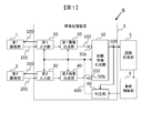
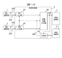
- FIG. 1 is a block diagram of an image processing system S including an image processing apparatus 3.
- the image processing system S includes a first imaging unit 1, a second imaging unit 2, an image processing device 3, a vehicle control unit 4, and a recognition processing unit 5.
- the image processing system S is mounted on a vehicle.
- a vehicle equipped with the image processing system S is also referred to as a "equipped vehicle”.
- the first imaging unit 1 is, for example, a camera.
- the first imaging unit 1 shoots a subject based on the shooting instruction 100 from the image processing device 3, and outputs the obtained image 101 to the image processing device 3.
- the first imaging unit 1 receives one imaging instruction 100
- the first imaging unit 1 performs so-called auto bracket imaging for imaging with two different exposure times, and outputs two images to the image processing apparatus 3.
- two types of exposure time are called “short exposure time” and "long exposure time”
- the images obtained by each exposure are called “image A” and "image B”. That is, the image 101 is an image having a plurality of exposure times different from each other, the image A and the image B.
- the fact that the exposure time is different is also referred to as "the photographing sensitivity is different". Since the image A and the image B are images obtained by photographing at strictly different times, for example, when the mounted vehicle is moving, the subject in the image A and the subject in the image B are at different positions in the photographed image Taken.
- the second imaging unit 2 is, for example, a camera.
- the second imaging unit 2 shoots a subject based on a shooting instruction 200 from the image processing device 3, and outputs the obtained image 201 to the image processing device 3.
- the function and operation of the second imaging unit 2 are the same as those of the first imaging unit 1.
- the image obtained in the short exposure time taken by the second imaging unit 2 is also called “image A”, and the image obtained in the long exposure time taken by the second imaging unit 2 is also called “image B”. That is, the image 201 is an image having a plurality of exposure times different from each other, the image A and the image B.
- the image processing apparatus 3 is a computer including a CPU, a ROM, a RAM, and an interface (not shown).
- the CPU develops a program stored in the ROM in the RAM and executes the program to realize the functions to be described later.
- the image processing device 3 may be configured by an ASIC or an FPGA instead of the CPU, the ROM, and the RAM.
- the image processing device 3 processes the images input from the first imaging unit 1 and the second imaging unit 2 to generate distance information, and outputs the distance information to the recognition processing unit 5.
- the image processing apparatus 3 has a first input unit 10 to which the images 101 of different imaging sensitivities supplied from the first imaging unit 1 are input, and a function of combining the images 101 of different imaging sensitivities into one image. It has a 1 image combining unit 20, a second input unit 30 to which an image 201 with different imaging sensitivity supplied from the second imaging unit 2 is input, and a function for combining the image 201 with different imaging sensitivity into one image And a second image combining unit 40.
- the first image combining unit 20 and the second image combining unit 40 may output one of the input images having different photographing sensitivity as it is.
- the first image combining unit 20 and the second image combining unit 40 output one of the image A, the image B, and the combined image (hereinafter, “combined image”). Which image to output is determined by the mode command signal 600 input from the determination unit 60 described later.
- the first image combining unit 20 and the second image combining unit 40 may always create a combined image, or may create a combined image only when outputting a combined image.
- the first input unit 10 and the second input unit 30 receive information indicating processing timing from the determination unit 60, and perform processing at that timing.
- the composition of the images in the first image composition unit 20 and the second image composition unit 40 is the creation of a so-called HDR (High Dynamic Range) image.
- the image output from the first image combining unit 20 is referred to as an image 102
- the image output from the second image combining unit 40 is referred to as an image 202.
- the first image combining unit 20 and the second image combining unit 40 may perform image processing other than combining processing such as enhancer processing and scaler processing. Enhancer processing is processing for extracting and sharpening edges, and scaler processing is processing for enlarging or reducing an image.
- the image processing device 3 further generates a distance information generation unit 50 that generates distance information using the image 102 supplied from the first image synthesis unit 20 and the image 202 supplied from the second image synthesis unit 40; And a determination unit 60 which determines an image to be supplied to the unit 50 and outputs a mode command signal 600.
- the distance information generation unit 50 generates distance information using the image 102 and the image 202 according to a known distance information generation algorithm.
- the first imaging unit 1 and the second imaging unit 2 have a predetermined baseline distance, and the positional relationship between the first imaging unit 1 and the second imaging unit 2 is known.
- the distance information generation unit 50 calculates the correspondence between the pixels of the first imaging unit 1 and the second imaging unit 2 and the parallax is larger as the distance to the subject is shorter, that is, the photographed image of the first imaging unit 1 and the first 2)
- the distance to the subject is calculated using the fact that the distance of the corresponding pixel in the photographed image of the imaging unit 2 is long.
- the calculated distance information is output to the recognition processing unit 5 as indicated by reference numeral 500.
- the distance information generation unit 50 also outputs the images input from the first image combining unit 20 and the second image combining unit 40 to the recognition processing unit 5 according to the content of the recognition process performed by the recognition processing unit 5.
- the distance information generation unit 50 includes a first port 50a and a second port 50b which are virtual input ports.
- the image output from the first image combining unit 20 is input from the first port 50a, and the image output from the second image combining unit 40 is input from the second port 50b.
- the distance information generation unit 50 receives information indicating processing timing from the determination unit 60, and performs processing at that timing.
- the distance information generation unit 50 may receive a non-composite image, that is, an image A or an image B, or a composite image.
- a non-composite image that is, an image A or an image B, or a composite image.
- the type of the image input from the first image combining unit 20 and the type of the image input from the second image combining unit 40 are always the same. Therefore, the distance information generation unit 50 generates the distance information using the image 102 and the image 202 in any case as well. Further, in the present embodiment, the time interval of the image input to the distance information generation unit 50, that is, the frame rate is constant.
- the vehicle control unit 4 is based on the distance information output from the recognition processing unit 5 or the information on the mounted vehicle acquired from the CAN network (not shown), the traveling information on the mounted vehicle in the image processing device 3 or the peripheral information on the mounted vehicle ( Hereinafter, "vehicle surrounding information" is output.
- the vehicle control unit 4 may further perform subject detection processing based on the information processed by the image processing device 3. Further, the vehicle control unit 4 may display the image obtained from the first imaging unit 1 as it is on a display device (not shown) connected to the vehicle control unit 4 as it is. The subject may be emphasized and displayed.
- the vehicle control unit 4 may further supply the information of the observation object detected by the vehicle control unit 4 to an information device (not shown) that processes traffic information such as map information and traffic congestion information.
- the recognition processing unit 5 performs various recognition processing as described later based on the information generated by the image processing device 3.
- the travel information output by the vehicle control unit 4 is, for example, the vehicle speed, the vehicle acceleration, the vehicle traveling direction, the steering angle, the brake information, the type of travel mode, the vehicle control information, and the like.
- the vehicle peripheral information output by the vehicle control unit 4 is, for example, the crowded degree of the host vehicle or the predicted value of the crowded degree, the distance to the subject, the speed of the subject, the relative speed with the subject, the host vehicle position information, the map information, Traffic congestion information, past accident information, road surface condition, and the like.
- the traveling mode mentioned as an example of the traveling state is a traveling mode based on a traveling path, a traveling mode based on a traveling situation, a traveling mode based on the surrounding natural environment, an energy saving mode traveling with power saving or low fuel consumption.
- the travel mode based on the travel path is, for example, a city travel mode, an expressway travel mode, and legal speed information.
- the travel mode based on the travel situation includes a traffic mode during traffic jam, a parking lot mode, and a travel mode according to the position and movement of surrounding vehicles.
- the travel modes based on the surrounding natural environment include a nighttime travel mode, a backlit travel mode, and the like.
- the map information is, for example, position information of a mounted vehicle on a map, road shape information, road surface feature information, road width information, lane information, road slope information, and the like.
- Road shape information is, for example, a T-junction or an intersection.
- Road surface feature information includes traffic lights, driveways, sidewalks, crossings, bicycle parking lots, car parking lots, pedestrian crossings, and the like.
- the traffic information includes traffic jam information, traffic restriction information such as speed limit and no-pass, and travel route guidance information for guiding to another travel route.
- Vehicle control information includes brake control, steering wheel control, accelerator control, in-vehicle lamp control, alarm sound generation, in-vehicle camera control, and observation objects in the vicinity of an imaging device connected to peripheral vehicles or remote center devices connected via a network Information output, etc.
- the recognition target in the recognition processing unit 5 is, for example, position information of a subject, type information, motion information, and danger information.
- the position information is, for example, the direction and distance from the mounted vehicle.
- the type information is information indicating types of pedestrians, adults, children, elderly people, animals, fallen rocks, bicycles, surrounding vehicles, surrounding structures, and curbs.
- the motion information is, for example, shaking of a pedestrian or a bicycle, jumping out, crossing, moving direction, moving speed, moving track, and the like.
- the danger information includes pedestrians jumping out, falling rocks, sudden stop, sudden deceleration, abnormal operation of nearby vehicles such as sudden steering, etc.
- the image A is effective for grasping the surrounding condition in the daytime when the amount of light is large.
- a pedestrian may move around the mounted vehicle, so quick detection is required, and the usefulness of the image A is high.
- the image B obtained in the long exposure time it is difficult to distinguishably record an object having high luminance, and it tends to be easy to record an object having low luminance so as to be distinguishable. Therefore, the image B is effective for grasping the surrounding situation at night when the amount of light is small.
- a dark area in the image A but an area in which the subject is identifiably recorded in the image B is a “dark area”, and an overexposed area in the image B is a discriminatively recorded in the image A
- the area where it is located is called "bright area”.
- the combining process of creating a combined image is realized by the following known method.
- the synthesis processing is composed of, for example, dynamic range expansion processing and gradation compression processing.
- the dynamic range expansion process is a process of superimposing the luminance information of the image A and the luminance information of the image B to increase the gradation of the luminance of each pixel.
- the luminance information of the image A and the luminance information of the image B may be multiplied by a coefficient according to the exposure time.
- only the luminance information is described as the processing target of the combining processing, but the same processing may be performed for each of RGB.
- the subsequent gradation compression processing is processing for reducing the gradation of the luminance of each pixel increased by the dynamic range expansion processing to a gradation that can be handled by the subsequent processing.
- the gradation compression processing may be omitted.
- the gradation is higher than that of the original image A and the image B, and overexposure and underexposure can be reduced.
- the mounted vehicle is moving, the subject is photographed at different positions in the image A and the image B, so the subject is unclear in the composite image. This tendency is more remarkable as the moving speed of the mounted vehicle is higher.
- the combining process has a sufficiently low processing load as compared to the process of calculating distance information performed by the distance information generating unit 50.
- the determination unit 60 stores seven preset criteria, that is, first to seventh criteria. Which criteria the determination unit 60 adopts is determined by an external input, for example, a setting by a user using the image processing system S or an operation command from an external server received from a communication interface (not shown). .
- the determination unit 60 determines an image to be input to the distance information generation unit 50 based on the adopted standard, the state of the mounted vehicle, and the like. The operation of the determination unit 60 in each of the first to seventh criteria will be described below.
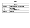
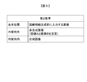
- FIG. 2 is a diagram for explaining the operation of the determination unit 60 in the case of employing the first reference.
- the determination unit 60 evaluates the vehicle speed of the mounted vehicle and determines whether the speed is higher than a predetermined speed S0.
- mode command signal 600 instructing output of image A and image B alternately is used as a first image combining unit 20 and a second image combining unit.
- Output to 40 When determining that the vehicle speed of the mounted vehicle is equal to or less than S0, determination unit 60 outputs mode command signal 600 instructing output of a combined image to first image combining unit 20 and second image combining unit 40.
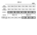
- FIG. 3 is a diagram showing an operation example of the first image combining unit 20 in the case of adopting the first reference.
- the first image combining unit 20 creates a combined image regardless of the mode command signal 600 input from the determination unit 60 for the sake of explanation.
- serial numbers are assigned to the created image in chronological order. That is, it indicates that the image A1 is created next to the image A0.
- the composite image is represented by adding a code C, and it is shown that the composite image C is created from the image A and the image B of the same number. That is, the image C0 was created from the image A0 and the image B0.
- the time has passed from the left to the right in the figure, and the vehicle speed was faster than S0 until the center time shown in the figure, but the vehicle speed became S0 or less after that.
- the vehicle speed when the vehicle speed is faster than S0, it is instructed that the first image combining unit 20 should alternately output a non-combined image. Therefore, at the bottom of FIG. 3, the image A and the image B are alternately input to the distance information generation unit 50 as illustrated as A0, B1, A2, and B3.
- the first image combining unit 20 is instructed to output a combined image, so the combined image is input to the distance information generating unit 50. Therefore, when the vehicle speed is equal to or less than S0, the recognition processing unit 5 can obtain the distance information of the subject photographed in the dark part and the bright part each time the distance information generation unit 50 calculates the distance information.
- the vehicle speed is less than or equal to S0, it is possible to calculate distance information for each of the image A and the image B, but there are the following problems.
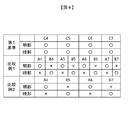
- FIG. 4 is a diagram showing whether or not calculation of distance information of a bright portion and a dark portion can be performed in the case of adopting the above-described first reference and in the case of employing Comparative Example 1 and Comparative Example 2.
- the upper part of FIG. 4 corresponds to the right half in FIG. 3, that is, the case where the vehicle speed is equal to or less than S0.
- the distance information generation unit 50 uses each of C4 to C7 and also uses a similar composite image output from the second image combining unit 40 exactly. Generate distance information. Since information on bright and dark portions can be obtained in the composite image, distance information on light and dark portions can be obtained when using any image. When the reference 1 is adopted, the number of calculations of the distance information in the range shown in FIG. 4 is four.
- Comparative Example 1 In the case of Comparative Example 1 shown in the middle part of FIG. 4, distance information is calculated using each of the image A and the image B without creating a composite image.
- the image A is used to calculate distance information
- distance information of the bright part can be obtained but distance information of the dark part can not be obtained.
- the image B is used to calculate distance information
- distance information of the dark part can be obtained but distance information of the bright part can not be obtained. That is, if the distance information calculated using image A and the distance information calculated using image B are combined, distance information of the bright part and the dark part can be obtained as in the case of adopting the first reference.
- the number of calculations of the distance information in the range shown in FIG. 4 is eight times, that is, twice that in the case of adopting the reference 1. In other words, when the first reference is adopted, the calculation cost of the distance information can be reduced to half as compared with Comparative Example 1.
- the image A and the image B are alternately used to generate distance information as in the case where the vehicle speed is faster than S0 in the first reference.
- the number of calculations of the distance information in the range shown in FIG. 4 is four, and the calculation cost of the distance information is the same as the first reference.
- distance information can be obtained only once every other time. In other words, in the case of employing the first reference, the frequency of acquiring distance information of the lightness and the dark part is twice that of the comparative example 2.
- the distance information generating unit 50 when the first reference is adopted, when the vehicle speed of the mounted vehicle exceeds the predetermined value S0, the distance information generating unit 50 generates the distance information for the non-composite image with less blurring of the object. Also, the distance information can be accurately calculated, and the recognition processing unit 5 can recognize a distant subject.
- the distance information is generated for the composite image, so as shown in the comparison with Comparative Example 1 and Comparative Example 2, the calculation cost and the frequency of obtaining distance information Excellent in terms of Furthermore, when the first standard is adopted, the processing load fluctuation can be prevented because the frequency of the image input to the distance information generation unit 50, that is, the frame rate, is constant even if the vehicle speed changes.
- the second to seventh criteria also have advantages over Comparative Example 1 and Comparative Example 2 when a composite image is used.
- FIG. 5 is a diagram for explaining the operation of the determination unit 60 in the case of employing the second reference.
- the determination unit 60 evaluates the position of the mounted vehicle and determines whether the mounted vehicle is in the urban area or outside the urban area. This determination may be made by the determination unit 60 on the basis of the position information of the mounted vehicle provided by the vehicle control unit 4 and the position information of the city area, or the inside and outside of the city area input from the vehicle control unit 4 You may judge by the signal which shows either.
- the determination unit 60 instructs the first image combining unit 20 and the second image combining unit 40 to output a mode command signal 600 for alternately outputting the image A and the image B.
- determination unit 60 outputs mode command signal 600 instructing output of a composite image to first image combining unit 20 and second image combining unit 40.
- the image processing device 3 can appropriately generate distance information based on the location of the mounted vehicle.
- FIG. 6 is a diagram for explaining the operation of the determination unit 60 in the case of employing the third reference.
- the determination unit 60 evaluates the vehicle speed and the position of the mounted vehicle. When it is determined that the mounted vehicle is in a city area and the vehicle speed is less than or equal to S0, determination unit 60 sets mode command signal 600 instructing output of a combined image to first image combining unit 20 and second image combining Output to section 40. Otherwise, the determination unit 60 outputs the mode command signal 600 instructing to output the image A and the image B alternately to the first image combining unit 20 and the second image combining unit 40.
- the image processing device 3 can appropriately generate distance information based on the vehicle speed and the location of the mounted vehicle.
- FIG. 7 is a diagram for explaining the operation of the determination unit 60 in the case where the fourth reference is adopted.
- the fourth reference is similar to the first reference, and differs from the first reference in that the ratio of the image A to the image B is 1: 3 when the vehicle speed is faster than the speed S0.
- the first image combining unit 20 outputs one image A, then outputs three images B, and then outputs one image A again.
- the fourth standard is high in the frequency of input of the image B having a long exposure time, and therefore, specifications such as nighttime and rainy weather are suitable. Note that, even at night, there is a large amount of light at the portion illuminated by the headlight, so recognition using the image A is effective. Even when this standard is adopted, the frame rate of the image input to the distance information generation unit 50 is constant regardless of the vehicle state.
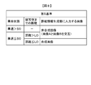
- FIG. 8 is a diagram for explaining the operation of the determination unit 60 in the case where the fifth reference is adopted.
- the determination unit 60 evaluates the vehicle speed of the mounted vehicle and the distance to the subject. If the determination unit 60 determines that the distance to the subject is a predetermined distance L0 or less and the vehicle speed is S0 or less, the mode command signal 600 instructing the output of the composite image is the first image combining unit 20 and It is output to the second image combining unit 40. Otherwise, the determination unit 60 outputs the mode command signal 600 instructing to output the image A and the image B alternately to the first image combining unit 20 and the second image combining unit 40. When there are a plurality of subjects, the distance of the closest subject is evaluated.
- the image processing device 3 can appropriately generate distance information based on the vehicle speed of the mounted vehicle and the distance to the object.
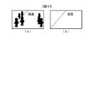
- FIG. 9 is a schematic view of an image obtained by photographing the front of the vehicle, FIG. 9 (a) shows a state at the time of congestion, and FIG. 9 (b) shows a state at the time of no congestion .
- the sixth standard uses the degree of congestion that indicates the degree of congestion.
- the congestion degree may be generated based on traffic information such as congestion information, or may be generated based on distance information or vehicle surrounding information.
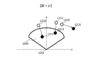
- FIG. 10 is a diagram showing an example of generation of the congestion degree.
- FIG. 10 shows subjects 1210, 1212, 1214 at time T0 indicated by white circles, subjects 1211, 1213, 1215 at time T0 + ⁇ t indicated by black circles, the vehicle position 1201, and the congestion degree determination area 1200.
- the subjects shown by reference numerals 1210 and 1211 are the same, the subjects shown by reference numerals 1212 and 1213 are the same, and the subjects shown by reference numerals 1214 and 1215 are the same.
- the degree of congestion is the number of objects present in the degree of congestion determination area 1200. At time T0, since the number of subjects in the congestion degree determination area 1200 is zero, the congestion degree is zero.
- the congestion degree is 2.
- the congestion degree determination area 1200 is one area, the congestion degree determination area 1200 may be divided into a plurality of areas, and the weighting for calculating the congestion degree may be changed according to the area.
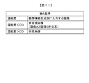
- FIG. 11 is a diagram for explaining the operation of the determination unit 60 in the case where the sixth reference is adopted.
- the determination unit 60 evaluates the degree of congestion described above. If the determination unit 60 determines that the congestion degree is equal to or less than the predetermined congestion degree C0, the mode command signal 600 instructing to output the image A and the image B alternately is used as the first image combining unit 20 and the second image Output to the combining unit 40.
- the determination unit 60 outputs a mode command signal 600 instructing output of a composite image to the first image combining unit 20 and the second image combining unit 40.
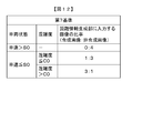
- FIG. 12 is a diagram for explaining the operation of the determination unit 60 in the case where the seventh reference is adopted.
- the determination unit 60 evaluates the vehicle speed and the degree of congestion of the mounted vehicle.
- the determination unit 60 sets the ratio of the composite image to the non-composite image to 0: 4. That is, the determination unit 60 outputs the mode command signal 600 instructing to alternately output the image A and the image B, which are non-combined images, to the first image combining unit 20 and the second image combining unit 40.
- the determination unit 60 If it is determined that the vehicle speed of the mounted vehicle is less than or equal to S0 and the congestion degree is less than or equal to a predetermined congestion degree C0, the determination unit 60 outputs the next mode command signal 600. That is, determination unit 60 outputs, to first image combining unit 20 and second image combining unit 40, mode command signal 600 instructing to output the ratio of the combined image and the non-combined image as 1: 3. If it is determined that the vehicle speed of the mounted vehicle is less than or equal to S0 and the congestion degree is greater than a predetermined congestion degree C0, the determination unit 60 outputs the next mode command signal 600.
- determination unit 60 outputs, to first image combining unit 20 and second image combining unit 40, mode command signal 600 instructing to output the ratio of the combined image and the non-combined image as 3: 1.
- mode command signal 600 instructing to output the ratio of the combined image and the non-combined image as 3: 1.
- the vehicle speed is equal to or less than S0
- two types of ratios are selected using the threshold C0, but the ratios may be changed stepwise according to the degree of congestion.
- the image processing device 3 is mounted on a mounted vehicle.
- the image processing apparatus 3 receives a first input unit 10 and a second input unit 30 to which a plurality of images having different imaging sensitivities are input, and a high-graded composite image generated using a plurality of images.
- the distance information generation unit 50 Based on at least one of the first port 50a and the second port 50b, the distance information generation unit 50 that generates predetermined feature information using an input image, the state of the mounted vehicle, and the peripheral state of the mounted vehicle
- a determination unit 60 which determines an image to be input to the distance information generation unit 50 as any one of a composite image, an image A, and an image B. Therefore, by inputting an appropriate image to the distance information generation unit 50 according to the situation, it is possible to efficiently obtain information of a subject in the bright area and a subject in the dark area, that is, a plurality of subjects with different brightness.
- the feature information generated by the distance information generation unit 50 is distance information. Therefore, the surroundings of the vehicle can be recognized using the distance information.
- the determination unit 60 further determines the frame rate of the image input to the distance information generation unit 50 based on at least one of the state of the vehicle and the state of the surroundings of the vehicle. Therefore, the processing load of the distance information generation unit 50 can be adjusted flexibly.
- the determination unit 60 maintains the frame rate of the image input to the distance information generation unit 50 within a predetermined range regardless of the state of the vehicle and the state of the surroundings of the vehicle. Therefore, the fluctuation of the processing load of the distance information generation unit 50 can be suppressed.
- the state of the vehicle includes at least one of the speed of the vehicle, the steering wheel operation information, and the position information of the vehicle.
- the condition around the vehicle includes the degree of congestion around the vehicle or the distance from the vehicle to the subject.
- a plurality of images having parallax captured by the first imaging unit 1 and the second imaging unit 2 are input to the first input unit 10 and the second input unit 30.
- the distance from the vehicle to the subject is a distance calculated using a plurality of images having parallax. Therefore, the distance can be calculated without using an additional sensor.
- the degree of congestion around the mounted vehicle is calculated based on the distance from the mounted vehicle to the subject and the relative velocity of the object with respect to the mounted vehicle. Therefore, the degree of congestion can be calculated by predicting the object moving in the vicinity of the mounted vehicle from the relative speed.
- the image processing device 3 generates a composite image using the plurality of images input to the first input unit 10 and the second input unit 30, and inputs the first image to the first port 50a and the second port 50b.
- a combining unit 20 and a second image combining unit 40 are provided. Therefore, even when another apparatus used together with the image processing apparatus 3 does not have a combining function, the above-described effect can be exhibited.
- the auto bracketing by the first imaging unit 1 and the second imaging unit 2 may be performed three or more times instead of twice. Further, the first imaging unit 1 and the second imaging unit 2 may change the aperture amount of the lens or the ISO sensitivity with the exposure time fixed, or may use these in combination.
- Modification 2 When the distance information generation unit 50 uses a non-composite image, in the above-described embodiment, images obtained by different bracket imaging such as A0, B1, etc. are used. However, if images obtained by the same bracket imaging are used, for example, the left half of FIG. 3, that is, non-composite images, images such as A0, B0, A2, B2, etc. may be used.
- the image processing device 3 may be configured to include the first imaging unit 1 and the second imaging unit 2. Furthermore, the image processing device 3 may be configured to include the recognition processing unit 5 and the vehicle control unit 4. According to this modification, the following effects can be obtained. (9) The image processing device 3 captures an image of the periphery of the mounted vehicle with different sensitivities, and inputs a plurality of images obtained by capturing to the first input unit 10 and the second input unit 30. A second imaging unit 2 is provided. Therefore, it is not necessary to connect the image processing device 3 to the first imaging unit 1 and the second imaging unit 2, and it can be used easily.
- the determination unit 60 only needs to store at least one of the first to seventh criteria. Further, any standard, for example, the seventh standard may be set by default, and may be changed by external input. Furthermore, the determination unit 60 may automatically select any one of the first to seventh standards according to a predetermined standard, for example, the ambient brightness or time zone.
- FIG. 1 A second embodiment of the image processing apparatus will be described with reference to FIG.
- the same components as in the first embodiment will be assigned the same reference numerals and differences will be mainly described.
- the points that are not particularly described are the same as in the first embodiment.
- the present embodiment differs from the first embodiment in that the imaging unit has a function of forming an image.
- FIG. 13 is a block diagram of an image processing system S in the second embodiment.
- 1 in the first embodiment is that the first imaging unit 1 has the function of the first image combining unit 20, and the second imaging unit 2 has the function of the second image combining unit 40. is there. Therefore, in the present embodiment, mode command signal 600 from determination unit 60 is input to first imaging unit 1 and second imaging unit 2 via first input unit 10 and second input unit 30.
- the first imaging unit 1 and the second imaging unit 2 output the non-composite image or the composite image to the first input unit 10 and the second input unit 30 according to the mode command signal 600.
- the first input unit 10 and the second input unit 30 output the input image to the distance information generation unit 50.
- FIG. 1 A third embodiment of the image processing apparatus will be described with reference to FIG.
- the same components as in the first embodiment will be assigned the same reference numerals and differences will be mainly described.
- the points that are not particularly described are the same as in the first embodiment.
- the present embodiment is different from the first embodiment mainly in that the image processing system S includes only one imaging unit.
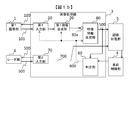
- FIG. 14 is a block diagram of an image processing system S in the third embodiment.
- the second embodiment differs from the first embodiment in FIG. 1 in that the second imaging unit 2, the second input unit 30, and the second image combining unit 40 are not provided.
- the feature information generating unit 80 is provided instead of the distance information generating unit 50.
- the feature information generation unit 80 performs, for example, edge information extraction processing, contour extraction processing, distance information generation, pattern matching processing, variance value calculation, average value calculation, and the like on the input image 102.
- FIG. 1 A fourth embodiment of the image processing apparatus will be described with reference to FIG.
- the same components as in the first embodiment will be assigned the same reference numerals and differences will be mainly described. Points that are not particularly described are the same as in the third embodiment.
- the present embodiment is different from the third embodiment in that the present embodiment mainly includes a radar unit that acquires surrounding information.
- FIG. 15 is a block diagram of an image processing system S in the fourth embodiment.
- the image processing system S further includes a radar unit 6, and the image processing apparatus 3 further includes a second input unit 70.
- the radar unit 6 is, for example, a two-dimensional or three-dimensional laser rangefinder.
- the second input unit 70 outputs an output instruction 500 to the radar unit 6 and acquires the distance information 501 from the radar unit 6.
- the second input unit 70 outputs the acquired distance information 501 as the distance information 700 to the recognition processing unit 5.
- the second input unit 70 may also output the distance information 700 to the feature information generation unit 80.
- FIGS. 16 to 17 A fifth embodiment of the image processing apparatus will be described with reference to FIGS. 16 to 17.
- the same components as in the first embodiment will be assigned the same reference numerals and differences will be mainly described.
- the points that are not particularly described are the same as in the first embodiment.
- the present embodiment is different from the first embodiment in that the processing is mainly changed according to the area of the photographed image.
- the first image combining unit 20 and the second image combining unit 40 divide the captured image into a plurality of processing areas, and the types of output images 102 and 202 for each processing area according to the mode command signal 600. And change the frame rate. Further, in the present embodiment, the first imaging unit 1 and the second imaging unit 2 perform imaging at 80 fps. Further, in the present embodiment, the distance information generation unit 50 generates distance information for each area of the input photographed image. Furthermore, the first image combining unit 20 and the second image combining unit 40 output an image for each area of the captured image at the frequency specified by the determination unit 60. For example, when an output at 80 fps is designated for an area, the input image for that area is output each time, but when output at 40 fps is output, an image is output every other time.
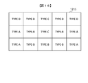
- FIG. 16 is a diagram showing an example of dividing the photographed image 1215 into processing areas.
- the captured image is divided into five horizontally and vertically divided into three areas, for a total of 15 areas, and each area is classified into one of four types, Type-A to D.
- the upper part, ie, the top row, of the photographed image 1215 is a region where a sky or a distant scenery is photographed, and four regions excluding one central region are classified into Type-D.
- the center in the horizontal direction is classified into Type-C except for the bottom row.
- the middle and lower stages at the left and right ends are classified as Type-A.
- the remaining area is Type-B.
- the area of Type-B is an area where the hood of a vehicle mounted and the road on which the vehicle is traveling are photographed.
- the area of Type-A corresponds to the left and right front of the mounted vehicle, and it is required to quickly detect obstacles such as pedestrians jumping out and approaching moving objects.
- FIG. 17 is a diagram for explaining the operation of the determination unit 60 in the case of adopting an eighth standard which is a standard specific to the fifth embodiment.
- determination unit 60 determines whether the vehicle speed of the mounted vehicle is faster than predetermined speed S0.
- the determination unit 60 instructs to output a non-composite image at 20 fps for all the regions.
- the area of Type-A outputs the composite image at 80 fps
- the area of Type-B outputs the composite image at 40 fps
- the area C outputs a non-composite image at 20 fps
- the area Type-D instructs to output a non-composite image at 10 fps.
- the determination unit 60 divides each of the plurality of images into a plurality of determination areas, and inputs each of the determination areas to the distance information generation unit 50 based on at least one of the state of the vehicle and the state around the vehicle.
- An image is determined as any one of a composite image, an image A, and an image B.
- the determination unit 60 determines the frame rate of the image input to the distance information generation unit 50 for each determination region based on at least one of the state of the mounted vehicle and the state of the periphery of the mounted vehicle. Therefore, depending on the situation, the frame rate of the area requiring special attention can be increased. Furthermore, it is possible to reduce the load on the distance information generation unit 50 by reducing the frame rate of the region where the necessity for calculating distance information is low, such as the region where the sky is captured.
- FIGS. 18 to 20 A sixth embodiment of the image processing apparatus will be described with reference to FIGS. 18 to 20.
- the same components as in the first embodiment will be assigned the same reference numerals and differences will be mainly described.
- the points that are not particularly described are the same as in the first embodiment.
- the present embodiment differs from the first embodiment mainly in that the distance information generation unit 50 calculates motion vector information.
- FIG. 18 is a block diagram of the distance information generation unit 50.
- the distance information generation unit 50 includes a processed image selection unit 2000 and a pattern matching unit 2001.
- the processed image selection unit 2000 outputs the input images 102 and 202 input at the same time according to the mode command signal 600 or two kinds of input images 102 (time T, time T-t) different in time. Switch whether to output.
- the pattern matching unit 2001 generates distance information based on the input images 102 and 202 input at the same time according to the mode command signal 600, or generates two types of input images 102 at different times (time T, time T). Switch whether to generate motion vector information based on -t).
- the distance information or motion vector information generated by the pattern matching unit 2001 is output as feature information 501. Note that the input image 202 may be used instead of the input image 102.
- FIG. 19 is a diagram for explaining the operation of the determination unit 60 in the case of adopting a distance information reference indicating an operation command to the distance information generation unit 50.
- the distance information reference is adopted for the operation command to the distance information generating unit 50
- the operation command to the first image combining unit 20 and the second image combining unit 40 adopts the sixth reference using the same judgment standard. Other criteria may be adopted.
- the determination unit 60 adopts the distance information standard
- the vehicle speed and the congestion degree of the mounted vehicle are evaluated.
- the vehicle speed is faster than the predetermined speed S0, a mode command signal 600 is issued which instructs to generate only the distance information regardless of the degree of congestion.
- a mode command signal 600 instructing generation of information is output.
- the vehicle speed is less than a predetermined speed S0 and the degree of congestion is greater than C0
- two frames in four frames generate motion vector information
- the remaining two frames generate distance information, whereby the vehicle is near the vehicle. Improve the motion detection performance of the subject.
- FIG. 20 is a diagram showing a processing example of the distance information generation unit 50 in the last case shown in FIG. 19, that is, when the vehicle speed is S0 or less and the congestion degree is larger than C0.
- time passes from the left to the right in the figure.
- a white square indicated by reference numeral 2201 indicates a motion vector information generation process
- a black square indicated by reference numeral 2200 indicates a distance information generation process.
- the distance information generation unit 50 switches processing every two frames as shown in FIG.
- the distance information generation unit 50 determines the ratio of generating the distance information and the motion vector information based on the command of the determination unit 60.
- the determination unit 60 determines the ratio of distance information and motion vector information output by the distance information generation unit 50 based on the distance information reference based on at least one of the state of the mounted vehicle and the state of the periphery of the mounted vehicle. Therefore, the image processing apparatus 3 can output distance information and motion vector information at an appropriate ratio according to the situation.
- the program is stored in the ROM (not shown) in the above-described embodiments and modifications, the program may be stored in a non-volatile memory (not shown).
- the image processing apparatus 3 may include an input / output interface (not shown), and a program may be read from another apparatus via a medium available to the image processing apparatus 3 when necessary.
- the medium refers to, for example, a storage medium removable from the input / output interface or a communication medium, that is, a wired, wireless, light or other network, or a carrier wave or digital signal propagating through the network.
- some or all of the functions implemented by the program may be implemented by a hardware circuit or an FPGA.
Landscapes
- Engineering & Computer Science (AREA)
- Physics & Mathematics (AREA)
- General Physics & Mathematics (AREA)
- Theoretical Computer Science (AREA)
- Computer Vision & Pattern Recognition (AREA)
- Multimedia (AREA)
- Electromagnetism (AREA)
- Power Engineering (AREA)
- Image Processing (AREA)
- Image Analysis (AREA)
- Closed-Circuit Television Systems (AREA)
- Traffic Control Systems (AREA)
Abstract
画像処理装置は、車両に搭載される画像処理装置であって、撮影感度の異なる複数の撮影画像が入力される撮影画像入力部と、複数の撮影画像を用いて生成される高階調化された合成画像が入力される合成画像入力部と、入力される画像を用いて所定の特徴情報を生成する特徴情報生成部と、車両の状態、および車両の周囲の状態の少なくとも一方に基づき、特徴情報生成部に入力する画像を、合成画像および撮影画像のいずれかに決定する判定部と、を備える。
Description
本発明は、画像処理装置に関する。
ステレオカメラを使用してカメラと観測対象物との距離を算出し、観測対象物の認識処理を行う技術が知られている。例えば特許文献1には、自動車等の移動体としての自車両400に搭載される画像処理装置1を、自車両進行方向前方領域(撮像領域)の撮像画像を撮像する撮像ユニット100で撮像した撮像画像を解析して、撮像領域内に存在する歩行者等の認識対象物を検知するステレオ画像処理部200を備えて構成する。ステレオ画像処理部200は、水平視差図に基づいて、認識対象物を検出し、当該認識対象物に対応する認識対象物領域輝度画像と、動的辞書258のパターン画像とを照合し、認識対象物であるか否か判定する構成が開示されている。
特許文献1に記載されている発明では、明るさが異なる複数の被写体の情報を得るためにはそれぞれの被写体にあわせた撮影条件で撮影し、得られたそれぞれの画像に対して処理を行う必要があるので、明るさに差がある複数の被写体の情報を得る計算コストが高い。
本発明の第1の態様による画像処理装置は、車両に搭載される画像処理装置であって、撮影感度の異なる複数の撮影画像が入力される撮影画像入力部と、前記複数の撮影画像を用いて生成される高階調化された合成画像が入力される合成画像入力部と、入力される画像を用いて所定の特徴情報を生成する特徴情報生成部と、前記車両の状態、および前記車両の周囲の状態の少なくとも一方に基づき、前記特徴情報生成部に入力する画像を、前記合成画像および前記撮影画像のいずれかに決定する判定部と、を備える。
本発明によれば、明るさに差がある複数の被写体の情報を効率よく得られる。
―第1の実施の形態―
以下、図1~図12を参照して、画像処理装置の第1の実施の形態を説明する。
以下、図1~図12を参照して、画像処理装置の第1の実施の形態を説明する。
(構成)
図1は、画像処理装置3を含む画像処理システムSの構成図である。画像処理システムSは、第1撮像部1と、第2撮像部2と、画像処理装置3と、車両制御部4と、認識処理部5とを備える。画像処理システムSは車両に搭載される。以下では、画像処理システムSを搭載する車両を、「搭載車両」とも呼ぶ。
図1は、画像処理装置3を含む画像処理システムSの構成図である。画像処理システムSは、第1撮像部1と、第2撮像部2と、画像処理装置3と、車両制御部4と、認識処理部5とを備える。画像処理システムSは車両に搭載される。以下では、画像処理システムSを搭載する車両を、「搭載車両」とも呼ぶ。
第1撮像部1は、たとえばカメラである。第1撮像部1は、画像処理装置3からの撮影指示100に基づき被写体を撮影し、得られた画像101を画像処理装置3に出力する。第1撮像部1は、一回の撮影指示100を受信すると、異なる2種類の露光時間で撮影する、いわゆるオートブラケット撮影を行い、2枚の画像を画像処理装置3に出力する。以下では、2種類の露光時間を「短露光時間」と「長露光時間」と呼び、それぞれの露光で得られた画像を「画像A」と「画像B」と呼ぶ。すなわち画像101は、画像Aと画像Bからなる複数の露光時間の異なる画像である。なお以下では、露光時間が異なることを「撮影感度が異なる」とも言う。なお画像Aと画像Bは厳密には異なる時刻に撮影して得られた画像なので、たとえば搭載車両が移動している場合には、画像Aにおける被写体と画像Bにおける被写体は撮影画像において異なる位置に撮影される。
第2撮像部2は、たとえばカメラである。第2撮像部2は画像処理装置3からの撮影指示200に基づき被写体を撮影し、得られた画像201を画像処理装置3に出力する。第2撮像部2の機能および動作は第1撮像部1と同様である。第2撮像部2が撮影した短露光時間で得られた画像も「画像A」と呼び、第2撮像部2が撮影した長露光時間で得られた画像も「画像B」と呼ぶ。すなわち画像201は、画像Aと画像Bからなる複数の露光時間の異なる画像である。
画像処理装置3は、不図示のCPU,ROM,RAM、およびインタフェースを備える計算機である。CPUがROMに格納されたプログラムをRAMに展開して実行することにより、後述する機能を実現する。ただし画像処理装置3は、CPU,ROM,およびRAMの代わりにASICやFPGAにより構成されてもよい。画像処理装置3は、第1撮像部1および第2撮像部2から入力された画像を処理して距離情報を生成し、認識処理部5に出力する。
画像処理装置3は、第1撮像部1から供給される撮影感度の異なる画像101が入力される第1入力部10と、撮影感度の異なる画像101を一枚の画像に合成する機能を備える第1画像合成部20と、第2撮像部2から供給される撮影感度の異なる画像201が入力される第2入力部30と、撮影感度の異なる画像201を一枚の画像に合成する機能を備える第2画像合成部40とを備える。ただし第1画像合成部20および第2画像合成部40は、入力された撮影感度の異なる画像のうちいずれか一方をそのまま出力することもある。すなわち第1画像合成部20および第2画像合成部40は、画像A、画像B、および合成した画像(以下、「合成画像」)のいずれかを出力する。いずれの画像を出力するかは、後述する判定部60から入力されるモード指令信号600により決定される。第1画像合成部20および第2画像合成部40は、常に合成画像を作成してもよいし、合成画像を出力する場合のみ合成画像を作成してもよい。また第1入力部10および第2入力部30は、判定部60から処理タイミングを示す情報が入力され、そのタイミングに処理を行う。
第1画像合成部20および第2画像合成部40における画像の合成は、いわゆるHDR(High Dynamic Range)画像の作成である。第1画像合成部20が出力する画像を画像102と呼び、第2画像合成部40が出力する画像を画像202と呼ぶ。なお第1画像合成部20および第2画像合成部40は、エンハンサ処理やスケーラ処理などの合成処理以外の画像処理を施してもよい。エンハンサ処理とはエッジを抽出して鮮鋭化する処理であり、スケーラ処理とは画像を拡大または縮小する処理である。画像処理装置3はさらに、第1画像合成部20から供給される画像102および第2画像合成部40から供給される画像202を用いて距離情報を生成する距離情報生成部50と、距離情報生成部50に供給する画像を決定し、モード指令信号600を出力する判定部60とを備える。
距離情報生成部50は、既知の距離情報生成アルゴリズムにより、画像102および画像202を用いて距離情報を生成する。第1撮像部1と第2撮像部2は、予め定められたベースライン距離を有しており、第1撮像部1と第2撮像部2の位置関係は既知である。距離情報生成部50は、第1撮像部1と第2撮像部2の各画素の対応関係を算出し、被写体との距離が近いほど視差が大きい、すなわち第1撮像部1の撮影画像と第2撮像部2の撮影画像における対応する画素の距離が遠いことを利用して被写体までの距離を計算する。計算した距離情報は、符号500で示すように認識処理部5に出力する。なお距離情報の算出には、前述のとおり第1撮像部1と第2撮像部2の各画素の対応関係を算出する必要があるため処理負荷が高い。また距離情報生成部50は、認識処理部5が実行する認識処理の内容に応じて、第1画像合成部20および第2画像合成部40から入力される画像も認識処理部5に出力する。
距離情報生成部50は仮想的な入力ポートである第1ポート50aおよび第2ポート50bを備える。第1画像合成部20が出力する画像は第1ポート50aから入力され、第2画像合成部40が出力する画像は第2ポート50bから入力される。距離情報生成部50は、判定部60から処理タイミングを示す情報が入力され、そのタイミングに処理を行う。
距離情報生成部50には、非合成画像、すなわち画像Aや画像Bが入力される場合と、合成画像が入力される場合がある。ただし第1画像合成部20から入力される画像の種類と、第2画像合成部40から入力される画像の種類は常に同一である。そのため距離情報生成部50は、いずれの場合であっても同様に画像102および画像202を用いて距離情報を生成する。また本実施の形態では、距離情報生成部50に入力される画像の時間間隔、すなわちフレームレートは一定である。
車両制御部4は、認識処理部5から出力される距離情報たは不図示のCANネットワークから取得する搭載車両の情報に基づき、画像処理装置3に搭載車両の走行情報または搭載車両の周辺情報(以下、「車両周辺情報」)を出力する。車両制御部4はさらに、画像処理装置3で処理した情報を元に被写体検知処理を行ってもよい。また車両制御部4は、車両制御部4に接続される不図示の表示機器に対して、第1撮像部1から得られた画像をそのまま表示してもよいし、被写体検出処理により検出された被写体を強調して表示してもよい。車両制御部4はさらに、地図情報や、渋滞情報などの交通情報を処理する不図示の情報機器に対して、車両制御部4が検知した観測対象物の情報を供給してもよい。認識処理部5は、画像処理装置3が生成した情報を元に後述するように様々な認識処理を行う。
(車両制御部4の機能の具体例)
車両制御部4が出力する走行情報とはたとえば、自車速度、自車加速度、自車進行方向、操舵角、ブレーキ情報、走行モードの種別、車両制御情報などである。車両制御部4が出力する車両周辺情報とはたとえば、自車周辺の混雑度または混雑度の予測値、被写体までの距離、被写体の速度、被写体との相対速度、自車位置情報、地図情報、交通渋滞情報、過去の事故情報、路面状態などである。
車両制御部4が出力する走行情報とはたとえば、自車速度、自車加速度、自車進行方向、操舵角、ブレーキ情報、走行モードの種別、車両制御情報などである。車両制御部4が出力する車両周辺情報とはたとえば、自車周辺の混雑度または混雑度の予測値、被写体までの距離、被写体の速度、被写体との相対速度、自車位置情報、地図情報、交通渋滞情報、過去の事故情報、路面状態などである。
走行状態の一例として挙げた走行モードとは、走行路に基づく走行モード、走行状況に基づく走行モード、周囲自然環境に基づく走行モード、省電力または少燃費で走行する省エネルギーモードなどである。走行路に基づく走行モードとは、市街地走行モード、高速道路走行モード、法定速度情報などである。走行状況に基づく走行モードとは、渋滞時走行モード、駐車場モード、周囲車両の位置や動きに応じた走行モードなどである。周囲自然環境に基づく走行モードとは、夜間時走行モード、逆光時走行モードなどである。
地図情報とは、地図上における搭載車両の位置情報、道路形状情報、道路面地物情報、路幅情報、車線情報、道路勾配情報などである。道路形状情報とは、T字路、交差点などである。道路面地物情報とは、信号、車道部、歩道部、踏切道、自転車駐輪場、自動車駐車場、横断歩道などである。交通情報とは、渋滞情報、速度制限や通行禁止などの交通規制情報、別の走行ルートに誘導する走行ルート誘導情報などである。車両制御情報とは、ブレーキ制御、ハンドル制御、アクセル制御、車載ランプ制御、警告音発生、車載カメラ制御、ネットワークを介して接続された周辺車両や遠隔地センタ機器への撮像装置周辺の観測対象物に関する情報出力などである。
(認識処理部5の機能の具体例)
認識処理部5における認識対象はたとえば、被写体の位置情報、種類情報、動作情報、危険情報である。位置情報とは、搭載車両からの方向と距離などである。種類情報とは、歩行者、大人、子供、高齢者、動物、落石、自転車、周辺車両、周辺構造物、縁石の種類を示す情報である。動作情報とは、歩行者や自転車のふらつき、飛び出し、横切り、移動方向、移動速度、移動軌跡などである。危険情報とは、歩行者飛び出し、落石、急停止や急減速や急ハンドルなど周辺車両の異常動作などである。
認識処理部5における認識対象はたとえば、被写体の位置情報、種類情報、動作情報、危険情報である。位置情報とは、搭載車両からの方向と距離などである。種類情報とは、歩行者、大人、子供、高齢者、動物、落石、自転車、周辺車両、周辺構造物、縁石の種類を示す情報である。動作情報とは、歩行者や自転車のふらつき、飛び出し、横切り、移動方向、移動速度、移動軌跡などである。危険情報とは、歩行者飛び出し、落石、急停止や急減速や急ハンドルなど周辺車両の異常動作などである。
(画像A,画像B,合成画像の特徴)
短露光時間で得られた画像Aには、輝度の高い被写体が識別可能に記録されやすく、輝度の低い被写体が識別可能に記録されにくい傾向にある。そのため画像Aは光の量が多い昼間における周囲の状況把握に有効である。また市街地では、搭載車両の周辺を歩行者が移動する可能性があるため迅速な検出が求められ、画像Aの有用性が高い。長露光時間で得られた画像Bには、輝度の高い被写体が識別可能に記録されにくく、輝度の低い被写体が識別可能に記録されやすい傾向にある。そのため画像Bは光の量が少ない夜間における周囲の状況把握に有効である。
短露光時間で得られた画像Aには、輝度の高い被写体が識別可能に記録されやすく、輝度の低い被写体が識別可能に記録されにくい傾向にある。そのため画像Aは光の量が多い昼間における周囲の状況把握に有効である。また市街地では、搭載車両の周辺を歩行者が移動する可能性があるため迅速な検出が求められ、画像Aの有用性が高い。長露光時間で得られた画像Bには、輝度の高い被写体が識別可能に記録されにくく、輝度の低い被写体が識別可能に記録されやすい傾向にある。そのため画像Bは光の量が少ない夜間における周囲の状況把握に有効である。
画像Aと画像Bを比較すると、画像Aにおいて光量が少なく黒くつぶれて表示される(以下、「黒つぶれ」)領域であっても、画像Bでは被写体が識別可能に記録されている可能性がある。また画像Bにおいて光量が多いために白く表示される(以下、「白とび」)領域であっても、画像Aでは被写体が識別可能に記録されている可能性がある。そこで、画像Aと画像Bを以下のように合成することで、黒つぶれや白飛びが軽減された合成画像が得られる。以下では、画像Aにおいて黒つぶれ領域であるが画像Bでは被写体が識別可能に記録されている領域を「暗部」、画像Bにおいて白とび領域であるが画像Aでは被写体が識別可能に記録されている領域を「明部」と呼ぶ。
合成画像を作成する合成処理は、以下のような既知の手法により実現される。合成処理は、たとえばダイナミックレンジ拡大処理と階調圧縮処理とから構成される。ダイナミックレンジ拡大処理は、画像Aの輝度情報と画像Bの輝度情報を重畳して各画素の輝度の階調を増加させる処理である。このとき画像Aの輝度情報と画像Bの輝度情報に、露光時間に応じた係数を乗じてもよい。なおここでは合成処理の処理対象として輝度情報のみを説明したが、RGBのそれぞれについて同様の処理を施してもよい。続く階調圧縮処理は、ダイナミックレンジ拡大処理により増加した各画素の輝度の階調を、後続する処理が対応可能な階調まで減少させる処理である。ただし距離情報生成部50が高階調の画像を処理可能な場合は、階調圧縮処理を省略してもよい。このようにして作成された合成画像では、元の画像Aおよび画像Bより高階調化されており、白飛びや黒つぶれが軽減される。ただし搭載車両が移動している場合には、画像Aと画像Bでは被写体が異なる位置に撮影されるので、合成画像において被写体は不鮮明となる。この傾向は搭載車両の移動速度が速いほど顕著である。なお合成処理は距離情報生成部50が実行する距離情報を算出する処理に比べると十分に処理負荷が低い。
(判定部60)
判定部60には、あらかじめ設定された7つの基準、すなわち第1基準~第7基準が記憶されている。判定部60がいずれの基準を採用するかは、外部からの入力、たとえば画像処理システムSを使用するユーザによる設定、または不図示の通信インタフェースから受信する外部のサーバからの動作指令により決定される。判定部60は、採用する基準、および搭載車両の状態などに基づき、距離情報生成部50に入力する画像を決定する。以下では第1基準~第7基準のそれぞれにおける判定部60の動作を説明する。
判定部60には、あらかじめ設定された7つの基準、すなわち第1基準~第7基準が記憶されている。判定部60がいずれの基準を採用するかは、外部からの入力、たとえば画像処理システムSを使用するユーザによる設定、または不図示の通信インタフェースから受信する外部のサーバからの動作指令により決定される。判定部60は、採用する基準、および搭載車両の状態などに基づき、距離情報生成部50に入力する画像を決定する。以下では第1基準~第7基準のそれぞれにおける判定部60の動作を説明する。
(第1基準)
図2は、第1基準を採用する場合の判定部60の動作を説明する図である。判定部60は、第1基準を採用する場合は、搭載車両の車速を評価し、所定の速度S0より速いか否かを判断する。判定部60は、搭載車両の車速がS0より速いと判断する場合は、画像Aと画像Bを交互に出力することを指示するモード指令信号600を第1画像合成部20および第2画像合成部40に出力する。判定部60は、搭載車両の車速がS0以下であると判断する場合は、合成画像の出力を指示するモード指令信号600を第1画像合成部20および第2画像合成部40に出力する。
図2は、第1基準を採用する場合の判定部60の動作を説明する図である。判定部60は、第1基準を採用する場合は、搭載車両の車速を評価し、所定の速度S0より速いか否かを判断する。判定部60は、搭載車両の車速がS0より速いと判断する場合は、画像Aと画像Bを交互に出力することを指示するモード指令信号600を第1画像合成部20および第2画像合成部40に出力する。判定部60は、搭載車両の車速がS0以下であると判断する場合は、合成画像の出力を指示するモード指令信号600を第1画像合成部20および第2画像合成部40に出力する。
図3は、第1基準を採用する場合の第1画像合成部20の動作例を示す図である。ただし図3では、説明のために第1画像合成部20は判定部60から入力されるモード指令信号600に関わらず合成画像を作成している。また図3では、作成された画像に時系列で連番を付与している。すなわち画像A0の次に画像A1が作成されたことを示している。またここでは合成画像に符号Cを付与して表し、合成画像Cは同一の番号の画像Aおよび画像Bから作成されたことを示している。すなわち画像A0と画像B0から画像C0が作成された。図3では図示左から右に時間が経過しており、図示する中央の時刻までは車速はS0より速かったが、それ以後は車速はS0以下となった。
このような場合において、車速がS0よりも速い場合は、第1画像合成部20は非合成画像を交互に出力すべきことが指示される。そのため図3の最下段に、A0、B1、A2、B3と図示されているように画像Aと画像Bが交互に距離情報生成部50に入力される。そして車速がS0以下になると、第1画像合成部20は合成画像を出力すべきことが指示されるので、合成画像が距離情報生成部50に入力される。そのため認識処理部5は、車速がS0以下の場合は距離情報生成部50が距離情報を算出するたびに暗部と明部に撮影された被写体の距離情報を得ることができる。なお、車速がS0以下の場合に、画像Aと画像Bのそれぞれについて距離情報を算出することも可能であるが以下の問題がある。
図4は、上述した第1基準を採用する場合と、比較例1および比較例2を採用する場合の明部および暗部の距離情報の算出の可否を示す図である。図4の上段は、図3における右半分、すなわち車速がS0以下の場合に相当する。図4の上段に示す基準1の場合は、C4~C7のそれぞれを使用して、正確には第2画像合成部40が出力する同様の合成画像もあわせて使用して距離情報生成部50は距離情報を生成する。そして合成画像では明部および暗部の情報が得られるので、いずれの画像を用いる場合にも明部および暗部の距離情報が得られる。基準1を採用する場合に、図4で示す範囲における距離情報の算出回数は4回である。
図4の中段に示す比較例1の場合は、合成画像を作成せずに画像Aと画像Bのそれぞれを使用して距離情報を算出する。距離情報の算出に画像Aを用いる場合は、明部の距離情報は得られるが暗部の距離情報は得られない。距離情報の算出に画像Bを用いる場合は、暗部の距離情報は得られるが明部の距離情報は得られない。すなわち、画像Aを用いて算出した距離情報と、画像Bを用いて算出した距離情報とをあわせれば、第1基準を採用する場合と同様に、明部および暗部の距離情報が得られる。しかし比較例1において、図4で示す範囲における距離情報の算出回数は8回、すなわち基準1を採用する場合の2倍である。換言すると、第1基準を採用する場合は比較例1に比べて距離情報の計算コストを半分に抑えることができる。
図4の下段に示す比較例2の場合は、第1基準において車速がS0より速い場合と同様に、画像Aおよび画像Bを交互に使用して距離情報を生成する。比較例2の場合は図4で示す範囲における距離情報の算出回数は4回であり、距離情報の計算コストは第1基準と同一である。しかし暗部および明部のそれぞれは、1回おきにしか距離情報が得られない。換言すると、第1基準を採用する場合は比較例2に比べて明度および暗部の距離情報の取得頻度が2倍である。
このように第1基準を採用すると、搭載車両の車速が所定値S0を上回る場合に、被写体のブレが少ない非合成画像を対象として距離情報を生成するので、距離情報生成部50は遠方の被写体も精度よく距離情報を算出することができ、認識処理部5が遠方の被写体も認識できる。一方、搭載車両の車速が所定値S0以下の場合は、合成画像を対象として距離情報を生成するので、比較例1および比較例2との比較で示したように計算コストおよび距離情報の取得頻度の点で優れる。さらに第1基準を採用する場合には、車速が変化しても距離情報生成部50に入力される画像の頻度、すなわちフレームレートが一定なので処理負荷の変動を防止することができる。なお以下に説明する第2基準~第7基準では言及しないが、第2基準~第7基準においても同様に、合成画像を使用する場合は比較例1および比較例2に対する利点を有する。
(第2基準)
図5は、第2基準を採用する場合の判定部60の動作を説明する図である。判定部60は、第2基準を採用する場合は、搭載車両の位置を評価し、搭載車両が市街地内と市街地外のいずれに居るかを判断する。この判断は、車両制御部4から提供される搭載車両の位置情報と市街地の位置情報に基づき判定部60が自ら判断してもよいし、車両制御部4から入力される市街地内と市街地外のいずれかを示す信号により判断してもよい。判定部60は、搭載車両が市街地外に存在すると判断する場合は、画像Aと画像Bを交互に出力することを指示するモード指令信号600を第1画像合成部20および第2画像合成部40に出力する。判定部60は、搭載車両が市街地内に存在すると判断する場合は、合成画像の出力を指示するモード指令信号600を第1画像合成部20および第2画像合成部40に出力する。第2基準を採用すると、画像処理装置3は搭載車両の所在地に基づき適切に距離情報を生成することができる。
図5は、第2基準を採用する場合の判定部60の動作を説明する図である。判定部60は、第2基準を採用する場合は、搭載車両の位置を評価し、搭載車両が市街地内と市街地外のいずれに居るかを判断する。この判断は、車両制御部4から提供される搭載車両の位置情報と市街地の位置情報に基づき判定部60が自ら判断してもよいし、車両制御部4から入力される市街地内と市街地外のいずれかを示す信号により判断してもよい。判定部60は、搭載車両が市街地外に存在すると判断する場合は、画像Aと画像Bを交互に出力することを指示するモード指令信号600を第1画像合成部20および第2画像合成部40に出力する。判定部60は、搭載車両が市街地内に存在すると判断する場合は、合成画像の出力を指示するモード指令信号600を第1画像合成部20および第2画像合成部40に出力する。第2基準を採用すると、画像処理装置3は搭載車両の所在地に基づき適切に距離情報を生成することができる。
(第3基準)
図6は、第3基準を採用する場合の判定部60の動作を説明する図である。判定部60は、第3基準を採用する場合は、搭載車両の車速および位置を評価する。判定部60は、搭載車両が市街地内に存在し、かつ車速がS0以下であると判断する場合は、合成画像の出力を指示するモード指令信号600を第1画像合成部20および第2画像合成部40に出力する。判定部60は、それ以外の場合は、画像Aと画像Bを交互に出力することを指示するモード指令信号600を第1画像合成部20および第2画像合成部40に出力する。第3基準を採用すると、画像処理装置3は搭載車両の車速および所在地に基づき適切に距離情報を生成することができる。
図6は、第3基準を採用する場合の判定部60の動作を説明する図である。判定部60は、第3基準を採用する場合は、搭載車両の車速および位置を評価する。判定部60は、搭載車両が市街地内に存在し、かつ車速がS0以下であると判断する場合は、合成画像の出力を指示するモード指令信号600を第1画像合成部20および第2画像合成部40に出力する。判定部60は、それ以外の場合は、画像Aと画像Bを交互に出力することを指示するモード指令信号600を第1画像合成部20および第2画像合成部40に出力する。第3基準を採用すると、画像処理装置3は搭載車両の車速および所在地に基づき適切に距離情報を生成することができる。
(第4基準)
図7は、第4基準を採用する場合の判定部60の動作を説明する図である。第4基準は第1基準と類似しており、車速が速度S0よりも速い場合に画像Aと画像Bの比率が1:3である点が第1基準と異なる。第4基準において車速が速度S0よりも速い場合は、第1画像合成部20は画像Aを1枚出力した後に画像Bを3枚出力し、その後再び画像Aを1枚出力する。第4基準は露光時間が長い画像Bの入力頻度が高いため、たとえば夜間や雨天時などの仕様が適している。なお夜間であってもヘッドライトに照らされる個所は光量が多いため、画像Aを用いた認識が有効である。また本基準を採用する場合でも、車両状態によらず距離情報生成部50に入力される画像のフレームレートは一定である。
図7は、第4基準を採用する場合の判定部60の動作を説明する図である。第4基準は第1基準と類似しており、車速が速度S0よりも速い場合に画像Aと画像Bの比率が1:3である点が第1基準と異なる。第4基準において車速が速度S0よりも速い場合は、第1画像合成部20は画像Aを1枚出力した後に画像Bを3枚出力し、その後再び画像Aを1枚出力する。第4基準は露光時間が長い画像Bの入力頻度が高いため、たとえば夜間や雨天時などの仕様が適している。なお夜間であってもヘッドライトに照らされる個所は光量が多いため、画像Aを用いた認識が有効である。また本基準を採用する場合でも、車両状態によらず距離情報生成部50に入力される画像のフレームレートは一定である。
(第5基準)
図8は、第5基準を採用する場合の判定部60の動作を説明する図である。判定部60は、第5基準を採用する場合は、搭載車両の車速および被写体までの距離を評価する。判定部60は、被写体までの距離が所定の距離L0以下であり、かつ車速がS0以下であると判断する場合は、合成画像の出力を指示するモード指令信号600を第1画像合成部20および第2画像合成部40に出力する。判定部60は、それ以外の場合は、画像Aと画像Bを交互に出力することを指示するモード指令信号600を第1画像合成部20および第2画像合成部40に出力する。なお被写体が複数存在する場合は、最も近い被写体の距離を評価する。第5基準を採用すると、画像処理装置3は搭載車両の車速および被写体までの距離に基づき適切に距離情報を生成することができる。
図8は、第5基準を採用する場合の判定部60の動作を説明する図である。判定部60は、第5基準を採用する場合は、搭載車両の車速および被写体までの距離を評価する。判定部60は、被写体までの距離が所定の距離L0以下であり、かつ車速がS0以下であると判断する場合は、合成画像の出力を指示するモード指令信号600を第1画像合成部20および第2画像合成部40に出力する。判定部60は、それ以外の場合は、画像Aと画像Bを交互に出力することを指示するモード指令信号600を第1画像合成部20および第2画像合成部40に出力する。なお被写体が複数存在する場合は、最も近い被写体の距離を評価する。第5基準を採用すると、画像処理装置3は搭載車両の車速および被写体までの距離に基づき適切に距離情報を生成することができる。
(第6基準)
図9は搭載車両の前方を撮影して得られる画像の模式図であり、図9(a)は混雑時の状況を示す図、図9(b)は非混雑時の状況を示す図である。第6基準では混雑の度合いを示す混雑度を利用する。混雑度は、渋滞情報などの交通情報を元に生成してもよいし、距離情報や車両周辺情報を元に生成してもよい。
図9は搭載車両の前方を撮影して得られる画像の模式図であり、図9(a)は混雑時の状況を示す図、図9(b)は非混雑時の状況を示す図である。第6基準では混雑の度合いを示す混雑度を利用する。混雑度は、渋滞情報などの交通情報を元に生成してもよいし、距離情報や車両周辺情報を元に生成してもよい。
図10は、混雑度の生成例を示す図である。図10には、白丸で示す時刻T0における被写体1210、1212、1214と、黒丸で示す時刻T0+Δtにおける被写体1211、1213、1215と、自車位置1201と、混雑度判定領域1200とを示している。符号1210と符号1211で示す被写体は同一であり、符号1212と符号1213で示す被写体は同一であり、符号1214と符号1215で示す被写体は同一である。ここでは混雑度は、混雑度判定領域1200に存在する被写体の数である。時刻T0では、混雑度判定領域1200内の被写体数が0であるため、混雑度は0である。時刻T0+Δtでは、混雑度判定領域1200内に被写体1211および被写体1213が存在するため、混雑度は2である。ただしここでは混雑度判定領域1200を一つの領域としたが、混雑度判定領域1200を複数の領域に分割し、領域により混雑度を算出する重みづけを変化させてもよい。
図11は、第6基準を採用する場合の判定部60の動作を説明する図である。判定部60は、第6基準を採用する場合は、上述した混雑度を評価する。判定部60は、混雑度が所定の混雑度C0以下であると判断する場合は画像Aと画像Bを交互に出力することを指示するモード指令信号600を第1画像合成部20および第2画像合成部40に出力する。判定部60は混雑度が所定の混雑度C0より大きいと判断する場合は、合成画像の出力を指示するモード指令信号600を第1画像合成部20および第2画像合成部40に出力する。
(第7基準)
図12は、第7基準を採用する場合の判定部60の動作を説明する図である。判定部60は、第7基準を採用する場合は、搭載車両の車速および混雑度を評価する。判定部60は、搭載車両の車速がS0より速いと判断する場合は、合成画像と非合成画像の割合を0:4とする。すなわち判定部60は、非合成画像である画像Aと画像Bを交互に出力することを指示するモード指令信号600を第1画像合成部20および第2画像合成部40に出力する。判定部60は、搭載車両の車速がS0以下であり、混雑度が所定の混雑度C0以下であると判断する場合は、次のモード指令信号600を出力する。すなわち判定部60は、合成画像と非合成画像の割合を1:3として出力することを指示するモード指令信号600を第1画像合成部20および第2画像合成部40に出力する。判定部60は、搭載車両の車速がS0以下であり、混雑度が所定の混雑度C0より大きいと判断する場合は、次のモード指令信号600を出力する。すなわち判定部60は、合成画像と非合成画像の割合を3:1として出力することを指示するモード指令信号600を第1画像合成部20および第2画像合成部40に出力する。なお車速がS0以下の場合に、閾値C0を用いて2種類の比率を選択しているが、混雑度に応じて段階的に比率を変更してもよい。
図12は、第7基準を採用する場合の判定部60の動作を説明する図である。判定部60は、第7基準を採用する場合は、搭載車両の車速および混雑度を評価する。判定部60は、搭載車両の車速がS0より速いと判断する場合は、合成画像と非合成画像の割合を0:4とする。すなわち判定部60は、非合成画像である画像Aと画像Bを交互に出力することを指示するモード指令信号600を第1画像合成部20および第2画像合成部40に出力する。判定部60は、搭載車両の車速がS0以下であり、混雑度が所定の混雑度C0以下であると判断する場合は、次のモード指令信号600を出力する。すなわち判定部60は、合成画像と非合成画像の割合を1:3として出力することを指示するモード指令信号600を第1画像合成部20および第2画像合成部40に出力する。判定部60は、搭載車両の車速がS0以下であり、混雑度が所定の混雑度C0より大きいと判断する場合は、次のモード指令信号600を出力する。すなわち判定部60は、合成画像と非合成画像の割合を3:1として出力することを指示するモード指令信号600を第1画像合成部20および第2画像合成部40に出力する。なお車速がS0以下の場合に、閾値C0を用いて2種類の比率を選択しているが、混雑度に応じて段階的に比率を変更してもよい。
上述した第1の実施の形態によれば、次の作用効果が得られる。
(1)画像処理装置3は、搭載車両に搭載される。画像処理装置3は、撮影感度の異なる複数の画像が入力される第1入力部10および第2入力部30と、複数の画像を用いて生成される高階調化された合成画像が入力される第1ポート50aおよび第2ポート50bと、入力される画像を用いて所定の特徴情報を生成する距離情報生成部50と、搭載車両の状態、および搭載車両の周囲の状態の少なくとも一方に基づき、距離情報生成部50に入力する画像を、合成画像、画像A、および画像Bのいずれかに決定する判定部60と、を備える。そのため状況に応じて適切な画像を距離情報生成部50に入力することで、明部の被写体および暗部の被写体、すなわち明るさに差がある複数の被写体の情報を効率よく得られる。
(1)画像処理装置3は、搭載車両に搭載される。画像処理装置3は、撮影感度の異なる複数の画像が入力される第1入力部10および第2入力部30と、複数の画像を用いて生成される高階調化された合成画像が入力される第1ポート50aおよび第2ポート50bと、入力される画像を用いて所定の特徴情報を生成する距離情報生成部50と、搭載車両の状態、および搭載車両の周囲の状態の少なくとも一方に基づき、距離情報生成部50に入力する画像を、合成画像、画像A、および画像Bのいずれかに決定する判定部60と、を備える。そのため状況に応じて適切な画像を距離情報生成部50に入力することで、明部の被写体および暗部の被写体、すなわち明るさに差がある複数の被写体の情報を効率よく得られる。
(2)距離情報生成部50が生成する特徴情報は距離情報である。そのため距離情報を用いて搭載車両の周囲を認識することができる。
(3)判定部60はさらに、車両の状態、および車両の周囲の状態の少なくとも一方に基づき距離情報生成部50に入力する画像のフレームレートを決定する。そのため距離情報生成部50の処理負荷を柔軟に調整できる。
(4)判定部60は、車両の状態、および車両の周囲の状態に関わらず、距離情報生成部50に入力する画像のフレームレートを所定の範囲内に維持する。そのため距離情報生成部50の処理負荷の変動を抑制することができる。
(5)車両の状態とは、車両の速度、ハンドル操作情報、および車両の位置情報の少なくとも一つを含む。車両の周囲の状態とは、車両の周囲における混雑の程度、または車両から被写体までの距離を含む。
(6)第1入力部10および第2入力部30には第1撮像部1および第2撮像部2が撮影した視差を有する複数の画像が入力される。車両から被写体までの距離は、視差を有する複数の画像を用いて算出された距離である。そのため追加のセンサを用いることなく距離を算出することができる。
(7)搭載車両の周囲における混雑の程度は、搭載車両から被写体までの距離と、搭載車両に対する被写体の相対速度に基づき算出される。そのため搭載車両の付近に移動する被写体を相対速度から予測して混雑度を算出することができる。
(8)画像処理装置3は、第1入力部10および第2入力部30に入力された複数の画像を用いて合成画像を生成し第1ポート50aおよび第2ポート50bに入力する第1画像合成部20および第2画像合成部40を備える。そのため画像処理装置3とともに用いられる他の装置が合成機能を有していない場合でも上述した効果を発揮することができる。
(変形例1)
第1撮像部1および第2撮像部2によるオートブラケット撮影は、2回ではなく3回以上行ってもよい。また第1撮像部1および第2撮像部2は、露光時間を一定としてレンズの絞り量やISO感度を変えてもよいし、これらを併用してもよい。
第1撮像部1および第2撮像部2によるオートブラケット撮影は、2回ではなく3回以上行ってもよい。また第1撮像部1および第2撮像部2は、露光時間を一定としてレンズの絞り量やISO感度を変えてもよいし、これらを併用してもよい。
(変形例2)
距離情報生成部50が非合成画像を使用する場合において、上述した実施の形態では、A0,B1,などのように異なるブラケット撮影で得られた画像を使用した。しかし同一のブラケット撮影で得られた画像を使用し、たとえば図3の左半分、すなわち非合成画像を用いる場合に、A0,B0,A2,B2,などの画像を使用してもよい。
距離情報生成部50が非合成画像を使用する場合において、上述した実施の形態では、A0,B1,などのように異なるブラケット撮影で得られた画像を使用した。しかし同一のブラケット撮影で得られた画像を使用し、たとえば図3の左半分、すなわち非合成画像を用いる場合に、A0,B0,A2,B2,などの画像を使用してもよい。
(変形例3)
画像処理装置3は、第1撮像部1および第2撮像部2を含んで構成されてもよい。さらに画像処理装置3は、認識処理部5や車両制御部4を含んで構成されてもよい。本変形例によれば次の作用効果が得られる。
(9)画像処理装置3は、搭載車両の周囲を異なる感度で撮影し、撮影して得られた複数の画像を第1入力部10および第2入力部30に入力する第1撮像部1および第2撮像部2を備える。そのため画像処理装置3を第1撮像部1および第2撮像部2と接続する必要がなく、簡便に使用することができる。
画像処理装置3は、第1撮像部1および第2撮像部2を含んで構成されてもよい。さらに画像処理装置3は、認識処理部5や車両制御部4を含んで構成されてもよい。本変形例によれば次の作用効果が得られる。
(9)画像処理装置3は、搭載車両の周囲を異なる感度で撮影し、撮影して得られた複数の画像を第1入力部10および第2入力部30に入力する第1撮像部1および第2撮像部2を備える。そのため画像処理装置3を第1撮像部1および第2撮像部2と接続する必要がなく、簡便に使用することができる。
(変形例4)
判定部60には、第1基準~第7基準の少なくとも1つの基準が記憶されていればよい。またいずれかの基準、たとえば第7基準がデフォルトで設定され、外部からの入力により変更可能な構成であってもよい。さらに判定部60は、所定の基準、たとえば周囲の明るさや時間帯により第1基準~第7基準のいずれかを自動で選択してもよい。
判定部60には、第1基準~第7基準の少なくとも1つの基準が記憶されていればよい。またいずれかの基準、たとえば第7基準がデフォルトで設定され、外部からの入力により変更可能な構成であってもよい。さらに判定部60は、所定の基準、たとえば周囲の明るさや時間帯により第1基準~第7基準のいずれかを自動で選択してもよい。
―第2の実施の形態―
図13を参照して、画像処理装置の第2の実施の形態を説明する。以下の説明では、第1の実施の形態と同じ構成要素には同じ符号を付して相違点を主に説明する。特に説明しない点については、第1の実施の形態と同じである。本実施の形態では、撮像部が画像を構成する機能を備える点で第1の実施の形態と異なる。
図13を参照して、画像処理装置の第2の実施の形態を説明する。以下の説明では、第1の実施の形態と同じ構成要素には同じ符号を付して相違点を主に説明する。特に説明しない点については、第1の実施の形態と同じである。本実施の形態では、撮像部が画像を構成する機能を備える点で第1の実施の形態と異なる。
図13は、第2の実施の形態における画像処理システムSの構成図である。第1の実施の形態における図1との相違点は、第1撮像部1が第1画像合成部20の機能を備え、第2撮像部2が第2画像合成部40の機能を備える点である。そのため本実施の形態では、判定部60からのモード指令信号600は、第1入力部10および第2入力部30を経由して第1撮像部1および第2撮像部2に入力される。そして第1撮像部1および第2撮像部2は、モード指令信号600に従い、非合成画像または合成画像を第1入力部10および第2入力部30に出力する。そして第1入力部10および第2入力部30は、入力された画像を距離情報生成部50に出力する。
―第3の実施の形態―
図14を参照して、画像処理装置の第3の実施の形態を説明する。以下の説明では、第1の実施の形態と同じ構成要素には同じ符号を付して相違点を主に説明する。特に説明しない点については、第1の実施の形態と同じである。本実施の形態では、主に、画像処理システムSが撮像部を1つのみ備える点で、第1の実施の形態と異なる。
図14を参照して、画像処理装置の第3の実施の形態を説明する。以下の説明では、第1の実施の形態と同じ構成要素には同じ符号を付して相違点を主に説明する。特に説明しない点については、第1の実施の形態と同じである。本実施の形態では、主に、画像処理システムSが撮像部を1つのみ備える点で、第1の実施の形態と異なる。
図14は、第3の実施の形態における画像処理システムSの構成図である。第1の実施の形態における図1との相違点は、本実施の形態では第2撮像部2、第2入力部30、および第2画像合成部40を備えない点である。また本実施の形態では、距離情報生成部50に代えて特徴情報生成部80を備える。特徴情報生成部80は、たとえば入力画像102に対するエッジ情報抽出処理、輪郭抽出処理、距離情報生成、パタンマッチング処理、分散値の算出、平均値の算出などを行う。
―第4の実施の形態―
図15を参照して、画像処理装置の第4の実施の形態を説明する。以下の説明では、第1の実施の形態と同じ構成要素には同じ符号を付して相違点を主に説明する。特に説明しない点については、第3の実施の形態と同じである。本実施の形態では、主に、周囲の情報を取得するレーダ部をさらに備える点で、第3の実施の形態と異なる。
図15を参照して、画像処理装置の第4の実施の形態を説明する。以下の説明では、第1の実施の形態と同じ構成要素には同じ符号を付して相違点を主に説明する。特に説明しない点については、第3の実施の形態と同じである。本実施の形態では、主に、周囲の情報を取得するレーダ部をさらに備える点で、第3の実施の形態と異なる。
図15は、第4の実施の形態における画像処理システムSの構成図である。第3の実施の形態における図14との相違点は、画像処理システムSがレーダ部6をさらに備え、画像処理装置3が第2入力部70をさらに備える点である。レーダ部6は、たとえば2次元または3次元のレーザ距離計である。第2入力部70は、レーダ部6に出力指示500を出力し、レーダ部6から距離情報501を取得する。第2入力部70は、取得した距離情報501を距離情報700として認識処理部5に出力する。ただし第2入力部70は距離情報700を特徴情報生成部80にも出力してもよい。
―第5の実施の形態―
図16~図17を参照して、画像処理装置の第5の実施の形態を説明する。以下の説明では、第1の実施の形態と同じ構成要素には同じ符号を付して相違点を主に説明する。特に説明しない点については、第1の実施の形態と同じである。本実施の形態では、主に、撮影画像の領域に応じて処理を異ならせる点で、第1の実施の形態と異なる。
図16~図17を参照して、画像処理装置の第5の実施の形態を説明する。以下の説明では、第1の実施の形態と同じ構成要素には同じ符号を付して相違点を主に説明する。特に説明しない点については、第1の実施の形態と同じである。本実施の形態では、主に、撮影画像の領域に応じて処理を異ならせる点で、第1の実施の形態と異なる。
本実施の形態では、第1画像合成部20および第2画像合成部40は、撮影画像を複数の処理領域に分割し、モード指令信号600に応じて処理領域毎に出力画像102、202の種類とフレームレートを変更する。また本実施の形態では、第1撮像部1および第2撮像部2は、80fpsで撮影を行っている。また本実施の形態では、距離情報生成部50は入力された撮影画像の領域ごとに距離情報を生成する。さらに第1画像合成部20および第2画像合成部40は、判定部60から指定された頻度で撮影画像の領域ごとに画像を出力する。たとえばある領域について80fpsでの出力を指定された場合は、その領域について入力された画像を毎回出力するが、40fpsでの出力をされた場合は、1回おきに画像を出力する。
図16は、撮影画像1215を処理領域に分割する一例を示す図である。図16に示す例では、撮影画像を横方向に5分割、縦方向に3分割、合計で15の領域に分割し、それぞれの領域をType-A~Dの4種類のいずれかに分類している。撮影画像1215の上部、すなわち最上段は空や遠方の風景が撮影される領域であり、中央の1領域を除いた4領域がType-Dに分類される。横方向の中央は、最下段を除いてType-Cに分類される。左右端の中段および下段は、Type-Aに分類される。そして残りの領域がType-Bである。Type-Bの領域は、搭載車両のボンネットや走行する道路が撮影される領域である。Type-Aの領域は、搭載車両の左右前方に相当しており歩行者の飛び出しや移動体の接近など迅速な障害物の検知が求められる。
図17は、第5の実施の形態に特有の基準である第8基準を採用する場合の判定部60の動作を説明する図である。判定部60は、第8基準を採用する場合は、搭載車両の車速が所定の速度S0より速いか否かを判断する。判定部60は、車速が所定の速度S0よりも速いと判断する場合は、全ての領域について非合成画像を20fpsで出力するように指示する。判定部60は、車速が所定の速度S0以下であると判断する場合は、Type-Aの領域は合成画像を80fpsで出力し、Type-Bの領域は合成画像を40fpsで出力し、Type-Cの領域は非合成画像を20fpsで出力し、Type-Dの領域は非合成画像を10fpsで出力するように指示する。
上述した第5の実施の形態によれば、次の作用効果が得られる。
(10)判定部60は、複数の画像のそれぞれを複数の判定領域に分割し、判定領域ごとに、車両の状態および車両の周囲の状態の少なくとも一方に基づき、距離情報生成部50に入力する画像を、合成画像、画像A,および画像Bのいずれかに決定する。
(10)判定部60は、複数の画像のそれぞれを複数の判定領域に分割し、判定領域ごとに、車両の状態および車両の周囲の状態の少なくとも一方に基づき、距離情報生成部50に入力する画像を、合成画像、画像A,および画像Bのいずれかに決定する。
(11)判定部60は、搭載車両の状態および搭載車両の周囲の状態の少なくとも一方に基づき、判定領域ごとに距離情報生成部50に入力する画像のフレームレートを決定する。そのため状況に応じて特に注意を要する領域のフレームレートを増加させることができる。さらに、空が撮影されている領域など距離情報を算出する必要性が乏しい領域のフレームレートを減少させ、距離情報生成部50の負荷を減少させることができる。
―第6の実施の形態―
図18~図20を参照して、画像処理装置の第6の実施の形態を説明する。以下の説明では、第1の実施の形態と同じ構成要素には同じ符号を付して相違点を主に説明する。特に説明しない点については、第1の実施の形態と同じである。本実施の形態では、主に、距離情報生成部50が動きベクトル情報を算出する点で、第1の実施の形態と異なる。
図18~図20を参照して、画像処理装置の第6の実施の形態を説明する。以下の説明では、第1の実施の形態と同じ構成要素には同じ符号を付して相違点を主に説明する。特に説明しない点については、第1の実施の形態と同じである。本実施の形態では、主に、距離情報生成部50が動きベクトル情報を算出する点で、第1の実施の形態と異なる。
図18は、距離情報生成部50の構成図である。距離情報生成部50は、処理画像選択部2000と、パタンマッチング部2001とを備える。処理画像選択部2000は、モード指令信号600に応じて、同じ時刻に入力される入力画像102と202を出力するか、時刻の異なる2種類の入力画像102(時刻T、時刻T―t)を出力するかを切替える。パタンマッチング部2001は、モード指令信号600に応じて、同じ時刻に入力される入力画像102と202を元に距離情報を生成するか、時刻の異なる2種類の入力画像102(時刻T、時刻T―t)を元に動きベクトル情報を生成するかを切替える。パタンマッチング部2001で生成した距離情報または動きベクトル情報は、特徴情報501として出力する。なお入力画像102に代えて入力画像202を用いてもよい。
図19は、距離情報生成部50への動作指令を示す距離情報基準を採用する場合の判定部60の動作を説明する図である。なお、距離情報生成部50への動作指令に距離情報基準を採用する場合は、第1画像合成部20および第2画像合成部40への動作指令は同様の判断基準を用いる第6基準を採用してもよいし、他の基準を採用してもよい。判定部60が距離情報基準を採用する場合は、搭載車両の車速および混雑度を評価する。車速が所定の速度S0よりも速い場合は、混雑度に関らず距離情報のみを生成することを指示するモード指令信号600を出力する。車速が所定の速度S0以下でありかつ混雑度がC0以下の場合は、車両近傍の被写体の動きを検知するために、4フレーム中の1フレームは動きベクトル情報を生成し、残り3フレームは距離情報を生成することを指示するモード指令信号600を出力する。また車速が所定の速度S0以下でありかつ混雑度がC0よりも大きい場合は、4フレーム中の2フレームは動きベクトル情報を生成し、残り2フレームは距離情報を生成することで、車両近傍の被写体の動き検知性能を向上させる。
図20は、図19で示した最後のケース、すなわち車速がS0以下でかつ混雑度がC0よりも大きい場合における、距離情報生成部50の処理例を示す図である。図20において、図示左から右に時間が経過している。図20では、符号2201で示す白抜きの四角は動きベクトル情報生成処理を示し、符号2200で示す黒塗りの四角は距離情報生成処理を示している。距離情報生成部50は、図19に示すように2フレームごとに処理を切替えている。
上述した第6の実施の形態によれば、次の作用効果が得られる。
(12)距離情報生成部50は、判定部60の指令に基づき距離情報および動きベクトル情報を生成する比率を決定する。判定部60は、搭載車両の状態、および搭載車両の周囲の状態の少なくとも一方に基づき、距離情報基準により、距離情報生成部50が出力する距離情報および動きベクトル情報の比率を決定する。そのため画像処理装置3は、状況に応じて距離情報と動きベクトル情報を適切な比率で出力することができる。
(12)距離情報生成部50は、判定部60の指令に基づき距離情報および動きベクトル情報を生成する比率を決定する。判定部60は、搭載車両の状態、および搭載車両の周囲の状態の少なくとも一方に基づき、距離情報基準により、距離情報生成部50が出力する距離情報および動きベクトル情報の比率を決定する。そのため画像処理装置3は、状況に応じて距離情報と動きベクトル情報を適切な比率で出力することができる。
上述した各実施の形態および変形例では、プログラムは不図示のROMに格納されるとしたが、プログラムは不図示の不揮発性メモリに格納されていてもよい。また、画像処理装置3が不図示の入出力インタフェースを備え、必要なときに入出力インタフェースと画像処理装置3が利用可能な媒体を介して、他の装置からプログラムが読み込まれてもよい。ここで媒体とは、たとえば入出力インタフェースに着脱可能な記憶媒体、または通信媒体、すなわち有線、無線、光などのネットワーク、または当該ネットワークを伝搬する搬送波やディジタル信号、を指す。また、プログラムにより実現される機能の一部または全部がハードウエア回路やFPGAにより実現されてもよい。
上述した各実施の形態および変形例は、それぞれ組み合わせてもよい。上記では、種々の実施の形態および変形例を説明したが、本発明はこれらの内容に限定されるものではない。本発明の技術的思想の範囲内で考えられるその他の態様も本発明の範囲内に含まれる。
次の優先権基礎出願の開示内容は引用文としてここに組み込まれる。
日本国特許出願2017-128821(2017年6月30日出願)
日本国特許出願2017-128821(2017年6月30日出願)
1…第1撮像部
2…第2撮像部
3…画像処理装置
4…車両制御部
5…認識処理部
10…第1入力部
20…第1画像合成部
30…第2入力部
40…第2画像合成部
50…距離情報生成部
60…判定部
70…第2入力部
80…特徴情報生成部
1200…混雑度判定領域
2000…処理画像選択部
2001…パタンマッチング部
2…第2撮像部
3…画像処理装置
4…車両制御部
5…認識処理部
10…第1入力部
20…第1画像合成部
30…第2入力部
40…第2画像合成部
50…距離情報生成部
60…判定部
70…第2入力部
80…特徴情報生成部
1200…混雑度判定領域
2000…処理画像選択部
2001…パタンマッチング部
Claims (12)
- 車両に搭載される画像処理装置であって、
撮影感度の異なる複数の撮影画像が入力される撮影画像入力部と、
前記複数の撮影画像を用いて生成される高階調化された合成画像が入力される合成画像入力部と、
入力される画像を用いて所定の特徴情報を生成する特徴情報生成部と、
前記車両の状態、および前記車両の周囲の状態の少なくとも一方に基づき、前記特徴情報生成部に入力する画像を、前記合成画像および前記撮影画像のいずれかに決定する判定部と、を備える画像処理装置。 - 請求項1に記載の画像処理装置において、
前記特徴情報生成部が生成する特徴情報は距離情報、および動きベクトル情報の少なくとも一方である画像処理装置。 - 請求項1に記載の画像処理装置において、
前記判定部はさらに、前記車両の状態、および前記車両の周囲の状態の少なくとも一方に基づき前記特徴情報生成部に入力する画像のフレームレートを決定する画像処理装置。 - 請求項3に記載の画像処理装置において、
前記判定部は、前記車両の状態、および前記車両の周囲の状態に関わらず、前記特徴情報生成部に入力する画像のフレームレートを所定の範囲内に維持する画像処理装置。 - 請求項1に記載の画像処理装置において、
前記車両の状態とは、前記車両の速度、および前記車両の位置情報の少なくとも一つを含み、
前記車両の周囲の状態とは、前記車両の周囲における混雑の程度、または前記車両から被写体までの距離を含む画像処理装置。 - 請求項5に記載の画像処理装置において、
前記撮影画像入力部には視差を有する前記撮影画像の組み合わせが複数の前記撮影感度についてそれぞれ入力され、
前記合成画像入力部には前記視差を有する複数の前記合成画像が入力され、
前記車両から前記被写体までの距離は、前記視差を有する複数の前記撮影画像または前記合成画像を用いて算出された距離である画像処理装置。 - 請求項5に記載の画像処理装置において、
前記車両の周囲における混雑の程度は、前記車両から前記被写体までの距離と、前記車両に対する前記被写体の相対速度に基づき算出される画像処理装置。 - 請求項1に記載の画像処理装置において、
前記判定部はさらに、前記撮影画像および前記合成画像のそれぞれを複数の判定領域に分割し、前記判定領域ごとに、前記車両の状態および前記車両の周囲の状態の少なくとも一方に基づき、前記特徴情報生成部に入力する画像を、前記合成画像および前記撮影画像のいずれかに決定する画像処理装置。 - 請求項8に記載の画像処理装置において、
前記判定部はさらに、前記車両の状態および前記車両の周囲の状態の少なくとも一方に基づき、前記判定領域ごとに前記特徴情報生成部に入力する画像のフレームレートを決定する画像処理装置。 - 請求項2に記載の画像処理装置において、
前記判定部はさらに、前記車両の状態、および前記車両の周囲の状態の少なくとも一方に基づき、前記特徴情報生成部が生成する前記距離情報および前記動きベクトル情報の比率を決定する画像処理装置。 - 請求項1に記載の画像処理装置において、
前記車両の周囲を異なる撮影感度で複数回撮影し、撮影して得られた前記複数の撮影画像を前記撮影画像入力部に入力する撮像部をさらに備える画像処理装置。 - 請求項1に記載の画像処理装置において、
前記撮影画像入力部に入力された前記複数の撮影画像を用いて前記合成画像を生成し前記合成画像入力部に入力する画像合成部をさらに備える画像処理装置。
Priority Applications (1)
| Application Number | Priority Date | Filing Date | Title |
|---|---|---|---|
| US16/627,117 US20200118280A1 (en) | 2017-06-30 | 2018-05-24 | Image Processing Device |
Applications Claiming Priority (2)
| Application Number | Priority Date | Filing Date | Title |
|---|---|---|---|
| JP2017128821A JP6847781B2 (ja) | 2017-06-30 | 2017-06-30 | 画像処理装置 |
| JP2017-128821 | 2017-06-30 |
Publications (1)
| Publication Number | Publication Date |
|---|---|
| WO2019003736A1 true WO2019003736A1 (ja) | 2019-01-03 |
Family
ID=64742998
Family Applications (1)
| Application Number | Title | Priority Date | Filing Date |
|---|---|---|---|
| PCT/JP2018/019980 Ceased WO2019003736A1 (ja) | 2017-06-30 | 2018-05-24 | 画像処理装置 |
Country Status (3)
| Country | Link |
|---|---|
| US (1) | US20200118280A1 (ja) |
| JP (1) | JP6847781B2 (ja) |
| WO (1) | WO2019003736A1 (ja) |
Families Citing this family (6)
| Publication number | Priority date | Publication date | Assignee | Title |
|---|---|---|---|---|
| JP2020140381A (ja) * | 2019-02-27 | 2020-09-03 | 本田技研工業株式会社 | 車両の制御システム、車両の制御方法、およびプログラム |
| KR102649032B1 (ko) * | 2019-04-26 | 2024-03-20 | 엘지전자 주식회사 | 자율주행 차량의 영상 처리 방법 |
| JP7400962B2 (ja) * | 2020-05-14 | 2023-12-19 | 日本電気株式会社 | 商品特定装置、商品特定方法、及びプログラム |
| US20240242360A1 (en) * | 2021-05-17 | 2024-07-18 | Nippon Telegraph And Telephone Corporation | Judgment device, judgment method, and judgment program |
| JP7780284B2 (ja) * | 2021-09-21 | 2025-12-04 | 株式会社Subaru | 車外環境認識装置 |
| DE102022211241A1 (de) * | 2022-10-24 | 2024-04-25 | Continental Autonomous Mobility Germany GmbH | Erkennen von Fahrbahnauflage auf einer Fahrbahn |
Citations (3)
| Publication number | Priority date | Publication date | Assignee | Title |
|---|---|---|---|---|
| WO2009060581A1 (ja) * | 2007-11-05 | 2009-05-14 | Fujitsu Ten Limited | 周辺監視装置、安全走行支援システム、及び車両 |
| JP2009177250A (ja) * | 2008-01-21 | 2009-08-06 | Fujitsu Ten Ltd | 車載用画像認識装置、車両状況判定装置および車載用画像認識方法 |
| JP2015050494A (ja) * | 2013-08-30 | 2015-03-16 | 日立オートモティブシステムズ株式会社 | 撮像装置 |
Family Cites Families (5)
| Publication number | Priority date | Publication date | Assignee | Title |
|---|---|---|---|---|
| JP4099011B2 (ja) * | 2002-07-10 | 2008-06-11 | 富士重工業株式会社 | 監視装置および監視方法 |
| JP4437532B2 (ja) * | 2004-03-26 | 2010-03-24 | オムロン株式会社 | 撮像装置及び画像処理方法 |
| JP4876080B2 (ja) * | 2008-01-25 | 2012-02-15 | 富士重工業株式会社 | 環境認識装置 |
| JP5746116B2 (ja) * | 2012-09-12 | 2015-07-08 | 本田技研工業株式会社 | 車両用監視装置 |
| JP6246629B2 (ja) * | 2014-03-14 | 2017-12-13 | 株式会社東芝 | 監視装置 |
-
2017
- 2017-06-30 JP JP2017128821A patent/JP6847781B2/ja active Active
-
2018
- 2018-05-24 US US16/627,117 patent/US20200118280A1/en not_active Abandoned
- 2018-05-24 WO PCT/JP2018/019980 patent/WO2019003736A1/ja not_active Ceased
Patent Citations (3)
| Publication number | Priority date | Publication date | Assignee | Title |
|---|---|---|---|---|
| WO2009060581A1 (ja) * | 2007-11-05 | 2009-05-14 | Fujitsu Ten Limited | 周辺監視装置、安全走行支援システム、及び車両 |
| JP2009177250A (ja) * | 2008-01-21 | 2009-08-06 | Fujitsu Ten Ltd | 車載用画像認識装置、車両状況判定装置および車載用画像認識方法 |
| JP2015050494A (ja) * | 2013-08-30 | 2015-03-16 | 日立オートモティブシステムズ株式会社 | 撮像装置 |
Also Published As
| Publication number | Publication date |
|---|---|
| JP2019012413A (ja) | 2019-01-24 |
| US20200118280A1 (en) | 2020-04-16 |
| JP6847781B2 (ja) | 2021-03-24 |
Similar Documents
| Publication | Publication Date | Title |
|---|---|---|
| JP6847781B2 (ja) | 画像処理装置 | |
| US11970156B1 (en) | Parking assistance using a stereo camera and an added light source | |
| US10504214B2 (en) | System and method for image presentation by a vehicle driver assist module | |
| JP4970516B2 (ja) | 周囲確認支援装置 | |
| JP6176028B2 (ja) | 車両制御システム、画像センサ | |
| CN109076163B (zh) | 成像控制装置、成像控制方法以及成像装置 | |
| JP7042185B2 (ja) | 距離算出装置 | |
| JP2023159121A (ja) | 情報処理装置、情報処理方法、プログラム、および移動体 | |
| CN104272345B (zh) | 车辆用显示装置和车辆用显示方法 | |
| US8305431B2 (en) | Device intended to support the driving of a motor vehicle comprising a system capable of capturing stereoscopic images | |
| JP2020501423A (ja) | 車両の周辺領域を状況に依存した捕捉を実施するためのカメラ手段及び方法 | |
| CN106295494B (zh) | 车外环境识别装置 | |
| JP2013147112A (ja) | 車両の走行環境認識装置 | |
| JP6668975B2 (ja) | 電子機器および自動車 | |
| JP2009017157A (ja) | 画像処理装置および方法、並びに、プログラム | |
| WO2012141053A1 (ja) | 画像処理装置 | |
| JP6468568B2 (ja) | 物体認識装置、モデル情報生成装置、物体認識方法、および物体認識プログラム | |
| JP2013041481A (ja) | 画像処理装置、画像処理システム、カメラ及びカメラシステム | |
| CN106295493A (zh) | 车外环境识别装置 | |
| JP4717073B2 (ja) | 風景解析装置及び方法 | |
| US12505568B1 (en) | Generating 3D visualization on 3D display utilizing 3D point cloud from multiple sources | |
| JP2013042404A (ja) | 画像処理装置、画像処理システム、カメラ、カメラシステム | |
| WO2021245935A1 (ja) | 情報処理装置、情報処理方法、及びプログラム | |
| JP2019061314A (ja) | 物体距離検出装置 | |
| JP4130601B2 (ja) | 対象物認識装置および対象物認識方法 |
Legal Events
| Date | Code | Title | Description |
|---|---|---|---|
| 121 | Ep: the epo has been informed by wipo that ep was designated in this application |
Ref document number: 18822824 Country of ref document: EP Kind code of ref document: A1 |
|
| NENP | Non-entry into the national phase |
Ref country code: DE |
|
| 122 | Ep: pct application non-entry in european phase |
Ref document number: 18822824 Country of ref document: EP Kind code of ref document: A1 |