WO2019003733A1 - Infrared ray-reflective substrate - Google Patents
Infrared ray-reflective substrate Download PDFInfo
- Publication number
- WO2019003733A1 WO2019003733A1 PCT/JP2018/019946 JP2018019946W WO2019003733A1 WO 2019003733 A1 WO2019003733 A1 WO 2019003733A1 JP 2018019946 W JP2018019946 W JP 2018019946W WO 2019003733 A1 WO2019003733 A1 WO 2019003733A1
- Authority
- WO
- WIPO (PCT)
- Prior art keywords
- layer
- infrared reflective
- substrate
- reflectance
- visible light
- Prior art date
Links
- 239000000758 substrate Substances 0.000 title claims abstract description 145
- 238000002834 transmittance Methods 0.000 claims abstract description 100
- 239000010410 layer Substances 0.000 claims description 302
- 239000004820 Pressure-sensitive adhesive Substances 0.000 claims description 14
- 239000011521 glass Substances 0.000 claims description 5
- 230000001681 protective effect Effects 0.000 claims description 5
- 239000000463 material Substances 0.000 abstract description 55
- 230000031700 light absorption Effects 0.000 abstract description 3
- 238000002310 reflectometry Methods 0.000 abstract description 2
- 229910052751 metal Inorganic materials 0.000 description 93
- 239000002184 metal Substances 0.000 description 93
- 239000010408 film Substances 0.000 description 91
- 229910044991 metal oxide Inorganic materials 0.000 description 63
- 150000004706 metal oxides Chemical class 0.000 description 63
- 229920005989 resin Polymers 0.000 description 50
- 239000011347 resin Substances 0.000 description 50
- 239000011241 protective layer Substances 0.000 description 39
- 239000000853 adhesive Substances 0.000 description 28
- 230000001070 adhesive effect Effects 0.000 description 28
- 230000000052 comparative effect Effects 0.000 description 25
- 125000006850 spacer group Chemical group 0.000 description 25
- 238000000034 method Methods 0.000 description 22
- 229910001316 Ag alloy Inorganic materials 0.000 description 21
- 239000012790 adhesive layer Substances 0.000 description 19
- 230000001965 increasing effect Effects 0.000 description 18
- BQCADISMDOOEFD-UHFFFAOYSA-N Silver Chemical compound [Ag] BQCADISMDOOEFD-UHFFFAOYSA-N 0.000 description 16
- -1 polyethylene terephthalate Polymers 0.000 description 16
- 229910052709 silver Inorganic materials 0.000 description 16
- 239000004332 silver Substances 0.000 description 16
- KDLHZDBZIXYQEI-UHFFFAOYSA-N Palladium Chemical compound [Pd] KDLHZDBZIXYQEI-UHFFFAOYSA-N 0.000 description 14
- GWEVSGVZZGPLCZ-UHFFFAOYSA-N Titan oxide Chemical compound O=[Ti]=O GWEVSGVZZGPLCZ-UHFFFAOYSA-N 0.000 description 14
- XLOMVQKBTHCTTD-UHFFFAOYSA-N Zinc monoxide Chemical compound [Zn]=O XLOMVQKBTHCTTD-UHFFFAOYSA-N 0.000 description 14
- 230000005540 biological transmission Effects 0.000 description 13
- 230000002708 enhancing effect Effects 0.000 description 13
- 230000003287 optical effect Effects 0.000 description 13
- 238000010521 absorption reaction Methods 0.000 description 12
- 239000002904 solvent Substances 0.000 description 12
- 239000005357 flat glass Substances 0.000 description 11
- 239000000126 substance Substances 0.000 description 11
- 238000001228 spectrum Methods 0.000 description 10
- OGIDPMRJRNCKJF-UHFFFAOYSA-N titanium oxide Inorganic materials [Ti]=O OGIDPMRJRNCKJF-UHFFFAOYSA-N 0.000 description 10
- ZWEHNKRNPOVVGH-UHFFFAOYSA-N 2-Butanone Chemical compound CCC(C)=O ZWEHNKRNPOVVGH-UHFFFAOYSA-N 0.000 description 9
- 150000002739 metals Chemical class 0.000 description 9
- 239000010949 copper Substances 0.000 description 8
- 230000006870 function Effects 0.000 description 8
- 239000012044 organic layer Substances 0.000 description 8
- RYGMFSIKBFXOCR-UHFFFAOYSA-N Copper Chemical compound [Cu] RYGMFSIKBFXOCR-UHFFFAOYSA-N 0.000 description 7
- 239000002131 composite material Substances 0.000 description 7
- 229910052802 copper Inorganic materials 0.000 description 7
- 239000003431 cross linking reagent Substances 0.000 description 7
- 239000010931 gold Substances 0.000 description 7
- 239000011787 zinc oxide Substances 0.000 description 7
- 229920002799 BoPET Polymers 0.000 description 6
- YMWUJEATGCHHMB-UHFFFAOYSA-N Dichloromethane Chemical compound ClCCl YMWUJEATGCHHMB-UHFFFAOYSA-N 0.000 description 6
- 238000000576 coating method Methods 0.000 description 6
- 238000001035 drying Methods 0.000 description 6
- 230000000694 effects Effects 0.000 description 6
- PCHJSUWPFVWCPO-UHFFFAOYSA-N gold Chemical compound [Au] PCHJSUWPFVWCPO-UHFFFAOYSA-N 0.000 description 6
- 229910052737 gold Inorganic materials 0.000 description 6
- 229920000139 polyethylene terephthalate Polymers 0.000 description 6
- 239000005020 polyethylene terephthalate Substances 0.000 description 6
- 229920000642 polymer Polymers 0.000 description 6
- 230000005855 radiation Effects 0.000 description 6
- 229920000459 Nitrile rubber Polymers 0.000 description 5
- 239000011248 coating agent Substances 0.000 description 5
- 230000007423 decrease Effects 0.000 description 5
- 230000006866 deterioration Effects 0.000 description 5
- 239000012535 impurity Substances 0.000 description 5
- 238000009413 insulation Methods 0.000 description 5
- 229920001225 polyester resin Polymers 0.000 description 5
- 239000004645 polyester resin Substances 0.000 description 5
- 230000002829 reductive effect Effects 0.000 description 5
- 230000035945 sensitivity Effects 0.000 description 5
- 238000004544 sputter deposition Methods 0.000 description 5
- XEEYBQQBJWHFJM-UHFFFAOYSA-N Iron Chemical compound [Fe] XEEYBQQBJWHFJM-UHFFFAOYSA-N 0.000 description 4
- 230000015572 biosynthetic process Effects 0.000 description 4
- 238000009835 boiling Methods 0.000 description 4
- 238000013461 design Methods 0.000 description 4
- 229910052763 palladium Inorganic materials 0.000 description 4
- 239000004814 polyurethane Substances 0.000 description 4
- 229920002635 polyurethane Polymers 0.000 description 4
- 229910001020 Au alloy Inorganic materials 0.000 description 3
- 239000004593 Epoxy Substances 0.000 description 3
- 229910052782 aluminium Inorganic materials 0.000 description 3
- 238000004364 calculation method Methods 0.000 description 3
- 239000003795 chemical substances by application Substances 0.000 description 3
- 229910052733 gallium Inorganic materials 0.000 description 3
- 239000003353 gold alloy Substances 0.000 description 3
- 238000010438 heat treatment Methods 0.000 description 3
- 238000010030 laminating Methods 0.000 description 3
- 238000005259 measurement Methods 0.000 description 3
- 239000000203 mixture Substances 0.000 description 3
- 229920000728 polyester Polymers 0.000 description 3
- 238000012545 processing Methods 0.000 description 3
- 239000010409 thin film Substances 0.000 description 3
- 239000010936 titanium Substances 0.000 description 3
- 239000004925 Acrylic resin Substances 0.000 description 2
- GYHNNYVSQQEPJS-UHFFFAOYSA-N Gallium Chemical compound [Ga] GYHNNYVSQQEPJS-UHFFFAOYSA-N 0.000 description 2
- 239000004696 Poly ether ether ketone Substances 0.000 description 2
- 239000004698 Polyethylene Substances 0.000 description 2
- RTAQQCXQSZGOHL-UHFFFAOYSA-N Titanium Chemical compound [Ti] RTAQQCXQSZGOHL-UHFFFAOYSA-N 0.000 description 2
- NIXOWILDQLNWCW-UHFFFAOYSA-N acrylic acid group Chemical group C(C=C)(=O)O NIXOWILDQLNWCW-UHFFFAOYSA-N 0.000 description 2
- 239000003522 acrylic cement Substances 0.000 description 2
- 239000000654 additive Substances 0.000 description 2
- XAGFODPZIPBFFR-UHFFFAOYSA-N aluminium Chemical compound [Al] XAGFODPZIPBFFR-UHFFFAOYSA-N 0.000 description 2
- 125000003118 aryl group Chemical group 0.000 description 2
- 230000008859 change Effects 0.000 description 2
- 238000011109 contamination Methods 0.000 description 2
- 239000007822 coupling agent Substances 0.000 description 2
- 238000001723 curing Methods 0.000 description 2
- 238000009820 dry lamination Methods 0.000 description 2
- 238000005566 electron beam evaporation Methods 0.000 description 2
- 238000005516 engineering process Methods 0.000 description 2
- 238000010884 ion-beam technique Methods 0.000 description 2
- 239000012939 laminating adhesive Substances 0.000 description 2
- 239000010955 niobium Substances 0.000 description 2
- 239000012788 optical film Substances 0.000 description 2
- 230000035699 permeability Effects 0.000 description 2
- 229920000570 polyether Polymers 0.000 description 2
- 229920002530 polyetherether ketone Polymers 0.000 description 2
- 229920000573 polyethylene Polymers 0.000 description 2
- 229920000098 polyolefin Polymers 0.000 description 2
- 238000002360 preparation method Methods 0.000 description 2
- 229920002803 thermoplastic polyurethane Polymers 0.000 description 2
- 229910052719 titanium Inorganic materials 0.000 description 2
- 238000009281 ultraviolet germicidal irradiation Methods 0.000 description 2
- 239000006097 ultraviolet radiation absorber Substances 0.000 description 2
- 238000001771 vacuum deposition Methods 0.000 description 2
- RNFJDJUURJAICM-UHFFFAOYSA-N 2,2,4,4,6,6-hexaphenoxy-1,3,5-triaza-2$l^{5},4$l^{5},6$l^{5}-triphosphacyclohexa-1,3,5-triene Chemical compound N=1P(OC=2C=CC=CC=2)(OC=2C=CC=CC=2)=NP(OC=2C=CC=CC=2)(OC=2C=CC=CC=2)=NP=1(OC=1C=CC=CC=1)OC1=CC=CC=C1 RNFJDJUURJAICM-UHFFFAOYSA-N 0.000 description 1
- 229920000178 Acrylic resin Polymers 0.000 description 1
- ZAMOUSCENKQFHK-UHFFFAOYSA-N Chlorine atom Chemical compound [Cl] ZAMOUSCENKQFHK-UHFFFAOYSA-N 0.000 description 1
- VYZAMTAEIAYCRO-UHFFFAOYSA-N Chromium Chemical compound [Cr] VYZAMTAEIAYCRO-UHFFFAOYSA-N 0.000 description 1
- JOYRKODLDBILNP-UHFFFAOYSA-N Ethyl urethane Chemical compound CCOC(N)=O JOYRKODLDBILNP-UHFFFAOYSA-N 0.000 description 1
- 241000282412 Homo Species 0.000 description 1
- OFOBLEOULBTSOW-UHFFFAOYSA-N Malonic acid Chemical compound OC(=O)CC(O)=O OFOBLEOULBTSOW-UHFFFAOYSA-N 0.000 description 1
- CBENFWSGALASAD-UHFFFAOYSA-N Ozone Chemical compound [O-][O+]=O CBENFWSGALASAD-UHFFFAOYSA-N 0.000 description 1
- 229910001252 Pd alloy Inorganic materials 0.000 description 1
- 239000004721 Polyphenylene oxide Substances 0.000 description 1
- 239000004743 Polypropylene Substances 0.000 description 1
- 229920002396 Polyurea Polymers 0.000 description 1
- 239000006087 Silane Coupling Agent Substances 0.000 description 1
- 229910001069 Ti alloy Inorganic materials 0.000 description 1
- ATJFFYVFTNAWJD-UHFFFAOYSA-N Tin Chemical compound [Sn] ATJFFYVFTNAWJD-UHFFFAOYSA-N 0.000 description 1
- WGCXSIWGFOQDEG-UHFFFAOYSA-N [Zn].[Sn].[In] Chemical compound [Zn].[Sn].[In] WGCXSIWGFOQDEG-UHFFFAOYSA-N 0.000 description 1
- 239000006096 absorbing agent Substances 0.000 description 1
- 229920006109 alicyclic polymer Polymers 0.000 description 1
- 239000003963 antioxidant agent Substances 0.000 description 1
- 239000002216 antistatic agent Substances 0.000 description 1
- QVGXLLKOCUKJST-UHFFFAOYSA-N atomic oxygen Chemical compound [O] QVGXLLKOCUKJST-UHFFFAOYSA-N 0.000 description 1
- 229910052797 bismuth Inorganic materials 0.000 description 1
- JCXGWMGPZLAOME-UHFFFAOYSA-N bismuth atom Chemical compound [Bi] JCXGWMGPZLAOME-UHFFFAOYSA-N 0.000 description 1
- 230000015556 catabolic process Effects 0.000 description 1
- 238000005229 chemical vapour deposition Methods 0.000 description 1
- 239000000460 chlorine Substances 0.000 description 1
- 229910052801 chlorine Inorganic materials 0.000 description 1
- 239000011651 chromium Substances 0.000 description 1
- BIJOYKCOMBZXAE-UHFFFAOYSA-N chromium iron nickel Chemical compound [Cr].[Fe].[Ni] BIJOYKCOMBZXAE-UHFFFAOYSA-N 0.000 description 1
- VNNRSPGTAMTISX-UHFFFAOYSA-N chromium nickel Chemical compound [Cr].[Ni] VNNRSPGTAMTISX-UHFFFAOYSA-N 0.000 description 1
- 229910000423 chromium oxide Inorganic materials 0.000 description 1
- 150000001875 compounds Chemical class 0.000 description 1
- 238000001816 cooling Methods 0.000 description 1
- 238000003851 corona treatment Methods 0.000 description 1
- 238000005260 corrosion Methods 0.000 description 1
- 230000007797 corrosion Effects 0.000 description 1
- 230000008878 coupling Effects 0.000 description 1
- 238000010168 coupling process Methods 0.000 description 1
- 238000005859 coupling reaction Methods 0.000 description 1
- 238000004132 cross linking Methods 0.000 description 1
- 238000007766 curtain coating Methods 0.000 description 1
- 125000004122 cyclic group Chemical group 0.000 description 1
- 150000001925 cycloalkenes Chemical class 0.000 description 1
- 238000006731 degradation reaction Methods 0.000 description 1
- 150000002009 diols Chemical class 0.000 description 1
- 229920001971 elastomer Polymers 0.000 description 1
- 125000003700 epoxy group Chemical group 0.000 description 1
- UHESRSKEBRADOO-UHFFFAOYSA-N ethyl carbamate;prop-2-enoic acid Chemical compound OC(=O)C=C.CCOC(N)=O UHESRSKEBRADOO-UHFFFAOYSA-N 0.000 description 1
- 239000003063 flame retardant Substances 0.000 description 1
- 239000003574 free electron Substances 0.000 description 1
- 125000000524 functional group Chemical group 0.000 description 1
- 229910052732 germanium Inorganic materials 0.000 description 1
- GNPVGFCGXDBREM-UHFFFAOYSA-N germanium atom Chemical compound [Ge] GNPVGFCGXDBREM-UHFFFAOYSA-N 0.000 description 1
- 238000007756 gravure coating Methods 0.000 description 1
- 229910052735 hafnium Inorganic materials 0.000 description 1
- VBJZVLUMGGDVMO-UHFFFAOYSA-N hafnium atom Chemical compound [Hf] VBJZVLUMGGDVMO-UHFFFAOYSA-N 0.000 description 1
- 150000002466 imines Chemical class 0.000 description 1
- 229910052738 indium Inorganic materials 0.000 description 1
- APFVFJFRJDLVQX-UHFFFAOYSA-N indium atom Chemical compound [In] APFVFJFRJDLVQX-UHFFFAOYSA-N 0.000 description 1
- NJWNEWQMQCGRDO-UHFFFAOYSA-N indium zinc Chemical compound [Zn].[In] NJWNEWQMQCGRDO-UHFFFAOYSA-N 0.000 description 1
- 238000009434 installation Methods 0.000 description 1
- 230000002452 interceptive effect Effects 0.000 description 1
- 229910052742 iron Inorganic materials 0.000 description 1
- UQSXHKLRYXJYBZ-UHFFFAOYSA-N iron oxide Inorganic materials [Fe]=O UQSXHKLRYXJYBZ-UHFFFAOYSA-N 0.000 description 1
- 239000012948 isocyanate Substances 0.000 description 1
- 150000002513 isocyanates Chemical class 0.000 description 1
- 238000003475 lamination Methods 0.000 description 1
- 239000000314 lubricant Substances 0.000 description 1
- 238000004519 manufacturing process Methods 0.000 description 1
- 230000004048 modification Effects 0.000 description 1
- 238000012986 modification Methods 0.000 description 1
- 238000013008 moisture curing Methods 0.000 description 1
- 229910000480 nickel oxide Inorganic materials 0.000 description 1
- 229910052758 niobium Inorganic materials 0.000 description 1
- GUCVJGMIXFAOAE-UHFFFAOYSA-N niobium atom Chemical compound [Nb] GUCVJGMIXFAOAE-UHFFFAOYSA-N 0.000 description 1
- 230000003647 oxidation Effects 0.000 description 1
- 238000007254 oxidation reaction Methods 0.000 description 1
- GNRSAWUEBMWBQH-UHFFFAOYSA-N oxonickel Chemical compound [Ni]=O GNRSAWUEBMWBQH-UHFFFAOYSA-N 0.000 description 1
- 239000001301 oxygen Substances 0.000 description 1
- 229910052760 oxygen Inorganic materials 0.000 description 1
- 150000002978 peroxides Chemical class 0.000 description 1
- 238000009832 plasma treatment Methods 0.000 description 1
- 239000004014 plasticizer Substances 0.000 description 1
- 229920000058 polyacrylate Polymers 0.000 description 1
- 229920001707 polybutylene terephthalate Polymers 0.000 description 1
- 229920000515 polycarbonate Polymers 0.000 description 1
- 239000004417 polycarbonate Substances 0.000 description 1
- 238000006068 polycondensation reaction Methods 0.000 description 1
- 229920000647 polyepoxide Polymers 0.000 description 1
- 239000011112 polyethylene naphthalate Substances 0.000 description 1
- 229920001155 polypropylene Polymers 0.000 description 1
- 229920001296 polysiloxane Polymers 0.000 description 1
- 229920005749 polyurethane resin Polymers 0.000 description 1
- 230000002265 prevention Effects 0.000 description 1
- 230000009993 protective function Effects 0.000 description 1
- 230000009467 reduction Effects 0.000 description 1
- 230000002441 reversible effect Effects 0.000 description 1
- 238000007127 saponification reaction Methods 0.000 description 1
- 238000006748 scratching Methods 0.000 description 1
- 230000002393 scratching effect Effects 0.000 description 1
- 229920002050 silicone resin Polymers 0.000 description 1
- 239000007787 solid Substances 0.000 description 1
- 238000005507 spraying Methods 0.000 description 1
- JBQYATWDVHIOAR-UHFFFAOYSA-N tellanylidenegermanium Chemical compound [Te]=[Ge] JBQYATWDVHIOAR-UHFFFAOYSA-N 0.000 description 1
- KKEYFWRCBNTPAC-UHFFFAOYSA-L terephthalate(2-) Chemical compound [O-]C(=O)C1=CC=C(C([O-])=O)C=C1 KKEYFWRCBNTPAC-UHFFFAOYSA-L 0.000 description 1
- 229910052716 thallium Inorganic materials 0.000 description 1
- BKVIYDNLLOSFOA-UHFFFAOYSA-N thallium Chemical compound [Tl] BKVIYDNLLOSFOA-UHFFFAOYSA-N 0.000 description 1
- 239000003017 thermal stabilizer Substances 0.000 description 1
- GZCWPZJOEIAXRU-UHFFFAOYSA-N tin zinc Chemical compound [Zn].[Sn] GZCWPZJOEIAXRU-UHFFFAOYSA-N 0.000 description 1
- 239000012780 transparent material Substances 0.000 description 1
- 229940124543 ultraviolet light absorber Drugs 0.000 description 1
- 125000000391 vinyl group Chemical group [H]C([*])=C([H])[H] 0.000 description 1
- XLYOFNOQVPJJNP-UHFFFAOYSA-N water Substances O XLYOFNOQVPJJNP-UHFFFAOYSA-N 0.000 description 1
- 229910001868 water Inorganic materials 0.000 description 1
- 230000003313 weakening effect Effects 0.000 description 1
- 229910052845 zircon Inorganic materials 0.000 description 1
- GFQYVLUOOAAOGM-UHFFFAOYSA-N zirconium(iv) silicate Chemical compound [Zr+4].[O-][Si]([O-])([O-])[O-] GFQYVLUOOAAOGM-UHFFFAOYSA-N 0.000 description 1
Images


Classifications
-
- G—PHYSICS
- G02—OPTICS
- G02B—OPTICAL ELEMENTS, SYSTEMS OR APPARATUS
- G02B5/00—Optical elements other than lenses
- G02B5/20—Filters
- G02B5/208—Filters for use with infrared or ultraviolet radiation, e.g. for separating visible light from infrared and/or ultraviolet radiation
-
- B—PERFORMING OPERATIONS; TRANSPORTING
- B32—LAYERED PRODUCTS
- B32B—LAYERED PRODUCTS, i.e. PRODUCTS BUILT-UP OF STRATA OF FLAT OR NON-FLAT, e.g. CELLULAR OR HONEYCOMB, FORM
- B32B17/00—Layered products essentially comprising sheet glass, or glass, slag, or like fibres
- B32B17/06—Layered products essentially comprising sheet glass, or glass, slag, or like fibres comprising glass as the main or only constituent of a layer, next to another layer of a specific material
- B32B17/061—Layered products essentially comprising sheet glass, or glass, slag, or like fibres comprising glass as the main or only constituent of a layer, next to another layer of a specific material of metal
-
- B—PERFORMING OPERATIONS; TRANSPORTING
- B32—LAYERED PRODUCTS
- B32B—LAYERED PRODUCTS, i.e. PRODUCTS BUILT-UP OF STRATA OF FLAT OR NON-FLAT, e.g. CELLULAR OR HONEYCOMB, FORM
- B32B7/00—Layered products characterised by the relation between layers; Layered products characterised by the relative orientation of features between layers, or by the relative values of a measurable parameter between layers, i.e. products comprising layers having different physical, chemical or physicochemical properties; Layered products characterised by the interconnection of layers
- B32B7/02—Physical, chemical or physicochemical properties
- B32B7/023—Optical properties
-
- C—CHEMISTRY; METALLURGY
- C09—DYES; PAINTS; POLISHES; NATURAL RESINS; ADHESIVES; COMPOSITIONS NOT OTHERWISE PROVIDED FOR; APPLICATIONS OF MATERIALS NOT OTHERWISE PROVIDED FOR
- C09J—ADHESIVES; NON-MECHANICAL ASPECTS OF ADHESIVE PROCESSES IN GENERAL; ADHESIVE PROCESSES NOT PROVIDED FOR ELSEWHERE; USE OF MATERIALS AS ADHESIVES
- C09J201/00—Adhesives based on unspecified macromolecular compounds
-
- C—CHEMISTRY; METALLURGY
- C09—DYES; PAINTS; POLISHES; NATURAL RESINS; ADHESIVES; COMPOSITIONS NOT OTHERWISE PROVIDED FOR; APPLICATIONS OF MATERIALS NOT OTHERWISE PROVIDED FOR
- C09J—ADHESIVES; NON-MECHANICAL ASPECTS OF ADHESIVE PROCESSES IN GENERAL; ADHESIVE PROCESSES NOT PROVIDED FOR ELSEWHERE; USE OF MATERIALS AS ADHESIVES
- C09J7/00—Adhesives in the form of films or foils
- C09J7/20—Adhesives in the form of films or foils characterised by their carriers
-
- G—PHYSICS
- G02—OPTICS
- G02B—OPTICAL ELEMENTS, SYSTEMS OR APPARATUS
- G02B5/00—Optical elements other than lenses
- G02B5/20—Filters
- G02B5/26—Reflecting filters
-
- G—PHYSICS
- G02—OPTICS
- G02B—OPTICAL ELEMENTS, SYSTEMS OR APPARATUS
- G02B5/00—Optical elements other than lenses
- G02B5/20—Filters
- G02B5/28—Interference filters
-
- G—PHYSICS
- G02—OPTICS
- G02B—OPTICAL ELEMENTS, SYSTEMS OR APPARATUS
- G02B5/00—Optical elements other than lenses
- G02B5/20—Filters
- G02B5/28—Interference filters
- G02B5/281—Interference filters designed for the infrared light
- G02B5/282—Interference filters designed for the infrared light reflecting for infrared and transparent for visible light, e.g. heat reflectors, laser protection
-
- G—PHYSICS
- G02—OPTICS
- G02B—OPTICAL ELEMENTS, SYSTEMS OR APPARATUS
- G02B5/00—Optical elements other than lenses
- G02B5/20—Filters
- G02B5/28—Interference filters
- G02B5/281—Interference filters designed for the infrared light
Definitions
- the present invention relates to an infrared reflective substrate comprising a thin film of an infrared reflective layer on a transparent substrate.
- An infrared reflective substrate provided with an infrared reflective layer on a substrate such as glass or film is conventionally known.
- Such an infrared reflective substrate is made, for example, by using a glass as a base material, the infrared reflective layer formed on the indoor side thereof and the window glass integrally, or using a film as a base on the indoor side of the window glass.
- near infrared rays such as sunlight which are incident from the outside into the room are reflected to provide a heat shielding effect.
- window glass it can also be used for other applications such as showcases if it is necessary to block external light.
- the heat shielding property is as high as possible, when the heat shielding property is enhanced, the transmittance of visible light is lowered and the visibility from the inside is deteriorated. That is, even if it is a prior art, although the heat insulation can be improved if the light transmittance is lowered, the visible light transmittance will also be lowered if the light transmission is enhanced by lowering the transmittance in this way. For this reason, in recent years, it has been desired to simultaneously achieve high light shielding properties and visible light transmittance.
- the visible light transmittance may be as low as 40%, but it has a heat shielding coefficient of 0.25 or less
- a heat shield having a heat shield coefficient of 0.5 or less may be required while maintaining a high visible light transmittance of 65% or more from the viewpoint of design and design.
- Patent Document 1 discloses an infrared reflective film including two metal layers. Such infrared reflective films are targeted to have high visible light transmission and low total solar heat transmission.
- the conventional infrared reflective substrate has, for example, a high visible light transmittance, and in the case of 70%, the heat shield coefficient exceeds about 0.55. Moreover, the visible light transmittance was low, and the infrared reflective substrate of 40% exceeded about 0.35. In fact, the visible light transmittances of Examples 1 and 2 of the infrared reflective film disclosed in Patent Document 1 are as high as 77% and 78%, but the solar heat gain rate (TSHT) is 55 and 53. When converted to a shielding coefficient, the values are as high as 62.5 and 60.2, and it is understood that the heat shielding properties are low in any of the above-described Examples 1 and 2.
- the problem to be solved by the present invention is to provide an infrared reflective substrate that has both high visible light transmittance and high heat shielding properties.
- the reflectance is high in the visible light region, and the visible light transmittance is correspondingly low.
- the reflectance is suppressed to a wavelength of around 700 nm to increase the transmittance. In the vicinity of 750 nm to the long wavelength side, it had a reflection characteristic that the light reflectance increased.
- the infrared reflective substrate is designed so that the reflectance increases from around 750 nm, the reflectance does not sufficiently increase in the near infrared region, and most of the near infrared light passes through the infrared reflective substrate. As a result, the thermal insulation of the infrared reflective substrate is reduced by the transmission of near infrared light.
- the sensitivity of the human eye varies depending on the wavelength even within the visible light range and is not uniform. For example, even in the visible light region, the sensitivity of the human eye to light having a wavelength near 550 nm and light having a wavelength near 700 nm is lower than the sensitivity to light having a wavelength near the center of the visible light region. Therefore, in order to correspond to the brightness actually felt by humans, in the calculation of the visible light transmittance, the weight ratio coefficient determined for each wavelength according to the sensitivity of the eye is multiplied by the ratio of the light actually transmitted. Calculated.
- FIG. 1 is a graph showing a weighting factor for calculating the visible light transmittance. In FIG.
- the horizontal axis indicates the wavelength
- the vertical axis indicates the weighting factor.
- the heavy duty coefficient is the highest at a wavelength of 550 nm and exhibits a value of less than 10. However, in the wavelength range of 650 nm to 700 nm, the heavy duty coefficient is 1 or less.
- the infrared reflective substrate of the present invention can have both high visible light transmittance and low heat shielding coefficient based on the fact that the reflectance of near infrared light can be increased while suppressing the influence on visible light transmittance. it can.
- the reflectance R 600 is preferably 10% or more and 60% or less. This is because the visible light transmittance can be increased by reducing the reflectance at a wavelength of 600 nm.
- the reflectance R 700 is preferably 25% or more and 85% or less. By increasing the reflectance at a wavelength of 700 nm, it is possible to reduce the shielding coefficient while keeping the influence on the visible light transmittance low. Moreover, it is preferable to make the ratio of the reflectance of wavelength 700 nm with respect to the reflectance of wavelength 600 nm 1.2 or more. By increasing the ratio of the reflectance, the polarizing film laminate can achieve both the visible light transmittance and the shielding coefficient at a higher level.
- the visible light transmittance can be increased by setting the visible light transmittance top wavelength between 450 nm and 650 nm.
- the transparent substrate is a film, and an adhesive layer may be provided on the surface opposite to the surface of the transparent substrate provided with the infrared reflective layer, or the transparent substrate is made of glass. It is also good.
- the infrared reflective substrate can be further provided with a transparent protective film on the infrared reflective layer to improve the durability.
- the visible light transmittance (VLT) and the shielding coefficient (SC) are in a trade-off relationship because the heat shielding coefficient decreases as the light transmission amount (transmission) decreases. Both parameters are considered
- the property of the infrared reflective film is represented by, for example, VLT (%)-160 ⁇ SC. This equation is based on the fact that it is possible to reduce the shielding coefficient by approximately 160 by approximately sacrificing the visible light transmittance by 1%.
- the infrared reflective substrate of the present invention may have, as one aspect, a characteristic that VLT (%) ⁇ 160 ⁇ SC is ⁇ 12 or more. Further, the value is more preferably 0 or more, more preferably 10 or more, and still more preferably 15 or more. Further, in consideration of other factors such as durability, the parameter may be 20 or less, or 17 or less.
- the infrared reflective substrate of the present invention has both high visible light transmittance and low heat shielding coefficient.
- Example 2 is a schematic view showing a layer configuration of Example 1;
- FIG. 18 is a schematic view illustrating a layer configuration of Example 8.
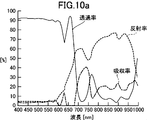
- 5 is a graph showing optical characteristics of Example 1.
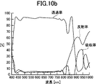
- 7 is a graph showing the optical characteristics of Comparative Example 1;
- 15 is a graph showing the optical characteristics of Example 9.
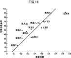
- 15 is a graph showing the optical characteristics of Comparative Example 4; It is a graph showing the relationship between the shielding coefficient and the visible light transmittance of the Example of this invention, and a comparative example.
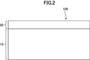
- FIG. 2 is a cross-sectional view schematically showing an example of the configuration of the infrared reflective substrate according to the embodiment of the present invention.
- the infrared reflective substrate 100 includes an infrared reflective layer 20 on one main surface of the transparent substrate 10.
- the infrared reflective layer 20 is in direct contact with the transparent substrate 10, but may have another layer in between.
- an undercoat layer may be provided between the infrared reflective layer 20 and the transparent substrate 10 in order to enhance the durability.
- a transparent protective film (not shown) for protecting the infrared reflective layer 10 may be provided on the upper surface of the infrared reflective layer, that is, the main surface on the opposite side to the transparent substrate 10.
- FIG. 3 is used to schematically explain the function of the infrared reflective substrate, and schematically shows a cross section of an example of the usage of infrared reflectance.
- the transparent substrate of the infrared reflective substrate is a film substrate.
- the main surface on the transparent base material side of the infrared reflective substrate 100 is bonded to the indoor side of the window glass 50 of a building or an automobile via the adhesive layer 60 or the like.
- the infrared reflection substrate 100 transmits visible light (VIS) from the outside and introduces it into the room, and reflects near infrared light (NIR) from the outside by the infrared reflection layer 20.
- the near-infrared reflection suppresses heat rays incident from the outside to the room due to sunlight and the like (a heat shielding effect is exhibited), so that the cooling efficiency in summer can be enhanced.
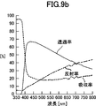
- FIG. 4 is a graph showing a typical example of the transmittance and reflectance of light incident from the base material side of the infrared reflective substrate 100 according to the embodiment of the present invention.
- the horizontal axis is wavelength (nm), and the vertical axis is transmittance (%) and reflectance (%).
- the infrared reflective substrate is attached to a single sheet glass conforming to JIS A 5759-2008 (architectural window glass film).
- JIS A 5759-2008 architectural window glass film.
- permeability and the reflectance from 100% becomes an absorptivity.
- the infrared reflective substrate 100 has a high transmittance of about 70% and a low reflectance of about 10% at 400 nm to 550 nm, which corresponds to the short wavelength side in the visible light region.
- the reflectance increases from around 550 nm to the long wavelength side, and the reflectance exceeds 50% at 700 nm near the long wavelength side boundary of the visible light region.
- the infrared reflective substrate 100 has a reflectance of over 50% at 700 nm to 800 nm which is a wavelength close to the visible light region.
- the reason why the near infrared light region has high reflectance of over 50% while being 700 nm to 800 nm close to the visible light region is that the slope of the reflectance is high in the wavelength region of 600 nm to 700 nm It is. Therefore, the infrared reflective substrate 100 has a high heat shielding property and a heat shielding coefficient of 0.50 because the light reflectance is high even in the near infrared light area near the visible light area.
- the slope of reflectance is determined based on the definition described in Equation 1.
- ⁇ wavelength (nm) (upper indicates long wavelength side, lower indicates wavelength on short wavelength side)
- R ⁇ reflectance at wavelength ⁇ (%)
- dR ⁇ upper- ⁇ lower slope of reflectance between wavelength ⁇ upper and wavelength ⁇ lower (% / nm)
- the infrared reflective substrate 100 is designed to have a high reflectance in the wavelength range of 600 nm to 700 nm, so the transmittance is reduced. However, as shown in FIG. 1, at wavelengths of 600 nm to 700 nm, since the heavy duty coefficient in the visible light transmittance calculation is low, the influence on the visible light transmittance is small. Therefore, the visible light transmittance of the infrared reflective substrate 100 has a high value of 68% despite the high thermal insulation.
- Transparent base material As the transparent substrate 10, those having a visible light transmittance of 80% or more are suitably used.
- the visible light transmittance is measured, for example, according to JIS A 5759-2008 (Building Window Glass Film).
- the thickness of the transparent substrate 10 is not particularly limited, but typically about 10 ⁇ m to 10 mm.
- a glass plate, a flexible transparent resin film, etc. are used as a transparent base material.
- a flexible transparent resin film is suitably used as the transparent substrate 10 from the viewpoint of enhancing the productivity of the infrared reflective substrate and facilitating the installation when bonding the infrared reflective substrate to a window glass or the like.
- the thickness thereof is preferably in the range of about 10 ⁇ m to 300 ⁇ m, preferably 100 ⁇ m or less, more preferably 50 ⁇ m or less, and still more preferably 40 ⁇ m or less.
- the resin material which comprises a transparent resin film base material is heat resistance.
- the resin material constituting the transparent resin film substrate include polyethylene terephthalate (PET), polyethylene naphthalate (PEN), polyetheretherketone (PEEK), polycarbonate (PC) and the like.
- the transparent substrate 10 is a transparent resin film substrate
- one having a cured resin layer on the surface of the transparent film in addition to the transparent film is preferable for the purpose of, for example, enhancing the mechanical strength of the infrared reflective substrate. Used. Further, by providing the cured resin layer on the side of the transparent film on which the infrared reflective layer 20 is formed, the scratch resistance of the infrared reflective layer 20, the transparent protective layer that can be formed thereon, and the like tends to be enhanced.
- the cured resin layer 12 can be formed, for example, by a method in which a cured film of an appropriate ultraviolet curable resin such as an acrylic resin or a silicone resin is attached on a transparent film. As the cured resin layer, one having high hardness is suitably used.
- Surface modification treatment such as treatment with an agent may be performed.
- the transparent substrate 10 is a resin film base, it is used to bond an infrared reflective substrate to a window glass or the like on the surface of the transparent substrate 10 opposite to the surface on which the infrared reflective layer 20 is formed.
- the pressure-sensitive adhesive layer 60 or the like may be attached.
- the pressure-sensitive adhesive layer 60 preferably has a high visible light transmittance and a small difference in refractive index from the transparent substrate 10.
- an acrylic pressure-sensitive adhesive pressure-sensitive adhesive
- the pressure-sensitive adhesive layer 60 preferably has a high visible light transmittance and a low ultraviolet light transmittance.
- the pressure-sensitive adhesive layer preferably contains an ultraviolet light absorber.
- degradation of the infrared reflectiveness layer resulting from the ultraviolet-ray from the outdoors can be suppressed also by using the transparent film base material etc. which contain an ultraviolet absorber.
- the exposed surface of the pressure-sensitive adhesive layer is preferably covered with a separator temporarily attached for the purpose of preventing contamination of the exposed surface until the infrared reflective substrate is put to practical use. Thereby, the contamination by the contact with the exterior of the exposed surface of an adhesive layer can be prevented in a usual handling state.
- the infrared reflective substrate can be used by being fitted in a frame or the like.
- Far infrared rays from the side can be reflected by the infrared reflection layer 20, and heat insulation can be imparted to both sides of the infrared reflection substrate.
- Such a configuration is particularly useful, for example, in a refrigerated showcase or a frozen showcase.
- the infrared reflective layer 20 in the embodiment of the present invention has a high light reflectance inclination from a wavelength of 600 nm to a wavelength of 700 nm.
- the following embodiments exist. It is not necessarily limited to
- FIG. 5 shows an infrared reflective layer 500 in an embodiment of the present invention.
- the infrared reflective layer 500 in FIG. 5 forms a Fabry-Perot resonator by two metal layers.
- the two metal layers play the role of a half mirror in a Fabry-Perot resonator.
- a transparent spacer layer is disposed between the two metal thin films, and light is blocked by selectively transmitting light of a specific wavelength and reflecting, interfering, or attenuating light of other wavelengths. .
- the range of wavelengths of light to be transmitted and the reflection are made The range of wavelengths of light can be changed.
- the infrared reflective layer 500 includes a first laminate 510, a transparent spacer layer 530, and a second laminate 550 in this order from the substrate 10 side.
- the first stacked body 510 includes a first metal oxide layer 512, a first metal layer 514, and a second metal oxide layer 516 in this order from the substrate 10 side, and the second stacked body is a base
- the third metal oxide layer 552, the second metal layer 554, and the fourth metal oxide layer 556 are provided in order from the material 10 side.
- the first metal layer 514 and the second metal layer 554 correspond to the two metal layers acting as a half mirror.
- the first metal layer is in direct contact with the first metal oxide layer and the second metal oxide layer, but for the protection of the metal layer or to adjust the refractive index difference of the interface. And other layers may be included between the two.
- the second metal layer is in direct contact with the third metal oxide layer and the fourth metal oxide layer, but other layers may be included between the two.
- Metal layers 514 and 554 have a central role in infrared reflection.
- metals having high near infrared reflectance such as silver, gold, copper, and aluminum, are preferably used.
- a silver alloy layer containing silver as a main component is preferably used as a metal layer sandwiched between metal oxide layers from the viewpoint of enhancing visible light transmittance and near infrared reflectance without increasing the number of laminations. Used.
- Silver has high free electron density, so that high reflectance of near infrared rays and far infrared rays can be realized, and the heat shielding effect and the heat insulating effect are excellent even when the number of laminated layers constituting the infrared reflection layer 20 is small. An infrared reflective film is obtained.
- the metal layers 514 and 554 preferably contain 75 to 99.9% by weight of silver.
- the silver content of the metal layer 15 is more preferably 80% by weight or more, further preferably 85% by weight or more, and particularly preferably 90% by weight or more.
- the wavelength selectivity of the transmittance and the reflectance can be enhanced, and the visible light transmittance can be enhanced.
- the visible light transmittance of the infrared reflective film tends to be enhanced.
- the metal layers 514 and 554 are preferably silver alloy layers containing metals other than silver for the purpose of improving the durability.
- the metal layers 514 and 554 preferably contain 0.1% by weight or more of a metal other than silver, more preferably 0.2% by weight or more, and further preferably 0.3% by weight or more. preferable.
- the metal added for the purpose of enhancing the durability of the metal layer palladium (Pd), gold (Au), copper (Cu), bismuth (Bi), germanium (Ge), gallium (Ga), etc. are preferable.
- Pd is most preferably used from the viewpoint of imparting high durability to silver.
- the addition amount of Pd or the like is increased, the durability of the metal layer tends to be improved.
- the addition amount of Pd or the like is excessively large, the visible light transmittance of the infrared reflective film tends to decrease. Therefore, 10 weight% or less is preferable, as for content of metals other than silver in a metal layer, 5 weight% or less is more preferable, 3 weight% or less is further more preferable, and 1 weight% or less is especially preferable.
- the metal layer is not limited to a silver alloy, and for example, from the viewpoint of enhancing the durability, a gold simple substance or a gold alloy containing gold as a main component may be used.
- the content of gold in the gold alloy is preferably 75 to 99.9% by weight.
- the content of gold in the metal layer is more preferably 80% by weight or more, still more preferably 85% by weight or more, and particularly preferably 90% by weight or more.
- silver as an impurity, for example, it is preferable to contain 1 to 25% by weight of silver, 10% by weight or less is more preferable, and 5% by weight or less is more preferable.
- the first metal layer 514 and the second metal layer 554 may be different metals, for example, while the second metal layer close to the surface and requiring high durability is a gold alloy,
- the metal layer 1 may be an inexpensive silver alloy.
- the film thicknesses of the first metal layer 514 and the second metal layer 554 are appropriately set in consideration of the refractive index and the like of the material so that the metal layer functions as a half mirror.
- the thickness of the metal layers 514 and 554 is preferably 4 nm to 25 nm, and more preferably 5 nm to 20 nm.
- a dry process such as a sputtering method, a vacuum evaporation method, or an electron beam evaporation method is preferable.
- the roll-to-roll film formation is possible, the film formation method common to the metal oxide layer can be adopted, and the film formation rate is high, so the sputtering method is preferable.
- the metal oxide layers 512, 516, 552 and 556 are provided for the purpose of achieving both high visible light transmittance and infrared reflectance by controlling the reflection amount of visible light at the interface with the metal layer.
- the metal oxide layer can also function as a protective layer for preventing deterioration of the metal layers 514 and 554.
- the refractive index to visible light of the metal oxide layer is preferably 1.5 or more, more preferably 1.6 or more, and still more preferably 1.7 or more. .
- oxides of metals such as thallium (Tl) and tin (Sn), or composite oxides of these metals.
- a composite metal oxide containing zinc oxide is suitably used as the material of the metal oxide layers 512, 516, 552 and 556.
- these metal oxide layers also have a function of protecting the metal layer, they are preferably amorphous.
- the metal oxide layer is an amorphous layer containing zinc oxide, the durability of the metal oxide layer itself is enhanced and the function as a protective layer for the metal layer is increased, so that the metal layer made of a silver alloy Deterioration of the
- the content of zinc oxide in the metal oxide layers 512, 516, 552 and 556 is preferably 3 parts by weight or more, more preferably 5 parts by weight or more, and 7 parts by weight with respect to 100 parts by weight in total of metal oxides.
- the above is more preferable.
- the content of zinc oxide is in the above range, the metal oxide layer tends to be an amorphous layer, and the durability tends to be enhanced.
- the content of zinc oxide is excessively large, the durability tends to decrease and the visible light transmittance tends to decrease.
- the content of zinc oxide in the metal oxide layers 512, 516, 552, 556 is preferably 60 parts by weight or less, more preferably 50 parts by weight or less, with respect to 100 parts by weight in total of the metal oxides. Parts by weight or less are more preferred.
- the composite metal oxide containing zinc oxide from the viewpoint of satisfying all of visible light transmittance, refractive index and durability, indium-zinc composite oxide (IZO), zinc-tin composite oxide (ZTO) Indium-tin-zinc complex oxide (ITZO) and the like are preferable.
- These composite oxides may further contain metals such as Al and Ga, and oxides of these metals.
- the thicknesses of the metal oxide layers 512, 516, 552, and 556 are appropriately set in consideration of the refractive index of the material and the like so that the infrared reflection layer transmits visible light and selectively reflects near infrared light. .
- the thickness of the metal oxide layers 512, 516, 552, 556 can be adjusted, for example, in the range of 3 nm to 80 nm, preferably 3 nm to 50 nm, more preferably 3 to 35 nm.
- the film forming method of the metal oxide layer is not particularly limited, it is preferable to form a film by a dry process such as a sputtering method, a vacuum evaporation method, a CVD method, an electron beam evaporation method, as in the metal layer.
- a dry process such as a sputtering method, a vacuum evaporation method, a CVD method, an electron beam evaporation method, as in the metal layer.
- the transparent spacer layer 530 acts as a spacer that adjusts its thickness to change the optical distance between the first metal layer and the second metal layer. And, by adjusting the optical characteristics such as the transmittance and the reflectance of the light from the substrate side by changing the above-mentioned optical distance, it is a high transmittance and a low reflectance at a wavelength of 600 nm, and At a wavelength of 700 nm, an infrared reflective film with low transmittance and high reflectance can be obtained.
- Such optical properties are determined according to the refractive index of the transparent spacer layer, and the materials and film thicknesses of the metal layer and the metal oxide layer.
- the optical film thickness of the transparent spacer layer (physical thickness and refractive index The product is preferably 70 nm to 300 nm, more preferably 80 nm to 250 nm, and still more preferably 90 nm to 200 nm. That is, considering that the refractive index of the transparent spacer layer is generally in the range of 1.3 to 1.7, the physical thickness of the transparent spacer layer is preferably 40 nm to 200 nm, for example, and 50 nm to 180 nm. More preferably, 60 nm to 160 nm is even more preferable.
- the infrared reflective substrate 500 may sequentially form each layer including the transparent spacer layer 530 on the transparent film substrate 10, but the transparent spacer layer 530 is provided with an adhesive function to be transparent different from the transparent film substrate 10.
- a second laminate 530 is formed on a film substrate (not shown), and is bonded to the first laminate 510 formed on the transparent film substrate 10 via the transparent spacer layer 530. , Can also create. Between the transparent film substrate 10 and the metal oxide layers 512 and 556 and between the transparent spacer layer 530 and the metal oxide layers 516 and 552 in this bonding method, compared to the method in which layers are sequentially formed. Excellent adhesion.
- the resin solution is applied on the metal oxide layer 516 to form the transparent spacer layer 530.
- An adhesive is preferably used as the transparent spacer layer 530 in order to enhance the adhesion between the metal oxide layers 516 and 552.
- the adhesive may be used as a mixture of two or more, and may be a two-component curable adhesive or a two-component solvent-based adhesive.
- the adhesive preferably has a crosslinking agent.
- the crosslinking agent include polyfunctional vinyl compounds, epoxy crosslinking agents, isocyanate crosslinking agents, imine crosslinking agents, peroxide crosslinking agents and the like.
- Bonding of the first laminate 510 and the second laminate 550 was performed by applying an adhesive onto one of the infrared reflection layers, and then immediately wet-laminating the laminate and drying the adhesive. You may carry out by any of the dry lamination method which bonds together later.
- the adhesive layer formed as the transparent spacer layer 530 has a great influence on optical characteristics such as transmission / reflection wavelength selectivity of the infrared reflective film. Therefore, it is preferable to use a dry lamination method that enables precise adjustment of the thickness of the adhesive layer.
- a dry laminating adhesive is used for bonding by the dry laminating method.
- a two-component curing type adhesive As a dry laminating adhesive, a two-component curing type adhesive, a two-component solvent type adhesive, a one-component non-solvent type adhesive, etc. may be mentioned.
- Acrylic-based as a two-component curing adhesive polyester-based, polyester / polyurethane-based, polyether / polyurethane-based, epoxy-based, one-component non-solvent-based adhesive (moisture curing type) as a two-component solvent-based adhesive
- Polyethers / polyurethanes, epoxys, etc. can be used.
- a resin solution such as an adhesive
- various methods such as gravure coating, kiss roll coating, reverse coating, various roll coating methods such as Mayer bar coating, spray coating, curtain coating, lip coating and the like.
- the first laminate 510 and the second laminate 550 are bonded together such that the second metal oxide layer 516 and the third metal oxide layer 552 face each other.
- heating may be performed as necessary.
- a crosslinking treatment be performed by heating, UV irradiation or the like after bonding.
- the metal layer and the metal oxide layer are two sheets of transparent Since the transparent base material disposed between the film base materials and forming the second laminate functions as a protective layer described later, it is excellent in physical durability such as scratch resistance. Furthermore, since the metal oxide layer is provided directly on each of the two transparent films without passing through the other resin layer, and the metal oxide layer is provided in contact with both sides of the metal layer, moisture etc. Intrusion is suppressed.
- the infrared reflective film of the present invention has high chemical durability, does not deteriorate the metal layer even when exposed to a high temperature and high humidity environment, and can maintain high thermal insulation and transparency.
- the transparent film substrate on the fourth metal oxide layer is not an essential component, it may be removed after laminating the first laminate 510 and the second laminate 530. .
- the transparent protective layer (not shown) is not essential, but on the second metal oxide layer of the infrared reflection layer, for the purpose of preventing scratching or deterioration of the metal oxide layer or the metal layer.
- a transparent protective layer may be provided.
- an organic substance is used as a material of the transparent protective layer from the viewpoint of forming the transparent protective layer within the heat resistant temperature range of the film substrate, an inorganic substance may be used.
- the transparent protective layer preferably has small absorption of far infrared radiation. If the absorptivity of far-infrared rays is large, the far-infrared rays in the room are absorbed by the transparent protective layer and dissipated to the outside by heat conduction, so the heat insulating properties of the infrared reflective film tend to be lowered. On the other hand, when the absorption of far infrared radiation by the transparent protective layer is small, the far infrared radiation is reflected indoors by the metal layers 514 and 554 of the infrared reflection layer, so that the heat insulating effect of the infrared reflection film is enhanced.
- Examples of methods for reducing the amount of far-infrared absorption by the transparent protective layer include methods for reducing the thickness of the transparent protective layer, and methods using materials having a small absorptivity of far-infrared as a material for the transparent protective layer.
- the thickness of a transparent protective layer and making far infrared ray absorption small 300 nm or less is preferable, 200 nm or less is more preferable, and 100 nm or less is more preferable.
- the thickness of the transparent protective layer is small, while the heat insulating effect can be enhanced by the reduction of the far infrared absorption amount, the function as a protective layer for enhancing the durability of the infrared reflective layer may be deteriorated. Therefore, when the thickness of the transparent protective layer is 200 nm or less, it is preferable that a material excellent in strength is used as the transparent protective layer, and the durability of the infrared reflective layer itself is also enhanced.
- the metal layers 514 and 554 are an alloy of silver and palladium, it is preferable to adjust the content of silver: palladium in a weight ratio of about 96: 4 to 98: 2.
- the material for the transparent protective layer has a small absorptivity of far infrared rays, the amount of far infrared absorption can be kept small even if the thickness of the protective layer is increased, thereby enhancing the protective effect on the infrared reflective layer be able to.
- the durability of the infrared reflective film can be enhanced without excessively increasing the content of palladium or the like in the metal layers 514 and 554, and thus both the visible light transmittance and the durability can be improved. Preferred above.
- a material which comprises a transparent protective layer for example, polyolefins, such as polyethylene and a polypropylene, alicyclic polymers, such as a cycloolefin type polymer, rubber-type polymers etc. are used suitably.
- the material constituting the transparent protective layer in addition to having a small absorptivity of far infrared rays, materials having high visible light transmittance, excellent adhesion to the infrared light reflecting layer, and excellent scratch resistance are suitably used. . From this point of view, rubber-based materials are particularly preferable, and among these, nitrile rubber-based materials are suitably used.
- the method for forming the transparent protective layer is not particularly limited, but, for example, a polymer such as hydrogenated nitrile rubber is dissolved in a solvent together with a crosslinking agent as necessary to prepare a solution, and this solution is placed on the infrared reflective layer 20 After application, it is formed by drying the solvent.
- the solvent is not particularly limited as long as it can dissolve the above-mentioned polymer, but low boiling point solvents such as methyl ethyl ketone (MEK) and methylene chloride are suitably used.
- the second laminate 550 is formed on the transparent base material, and the second laminate 550 is formed into the first laminate 510 through the transparent spacer layer 530 made of an adhesive.
- the transparent substrate may be used as a transparent protective layer so that the transparent substrate has a thickness and a material suitable for the transparent protective layer.
- coupling agents such as silane coupling agents and titanium coupling agents, leveling agents, ultraviolet absorbers, antioxidants, thermal stabilizer lubricants, plasticizers, coloration prevention Additives, such as an agent, a flame retardant, and an antistatic agent may be included.
- the content of these additives may be appropriately adjusted within the range that does not impair the object of the present invention, but the content of the polymer in the transparent protective layer is preferably 80% by weight or more.
- the content of the hydrogenated nitrile rubber in the transparent protective layer is preferably 90% by weight or more, more preferably 95% by weight or more, and 99% by weight The above is more preferable.
- the thickness of the transparent protective layer is preferably 1 ⁇ m to 20 ⁇ m, more preferably 2 ⁇ m to 15 ⁇ m, and 3 ⁇ m to 10 ⁇ m More preferable.
- the protective layer itself has sufficient physical strength, and the protective function of the infrared reflective layer can be enhanced, and the amount of absorption of far infrared rays can be reduced.
- the infrared reflective substrate 500 of the present invention comprises the first metal oxide layer, the first metal layer, the second metal oxide layer, the adhesive layer, and the like on one main surface of the transparent film substrate 10.
- the infrared ray reflection layer comprising the third metal oxide layer, the second metal layer, and the fourth metal oxide layer
- an additional layer may be provided depending on the use situation.
- a hard coat layer, an easily bonding layer or the like may be provided for the purpose of enhancing the strength of the film.
- a transparent material having a high visible light transmittance is preferably used.
- the refractive index (material) and thickness of each layer can be adjusted to make the transmittance of visible light with a wavelength of 600 nm or less 50% or more, more preferably 55% or more, 60% or more is still more preferable.
- the transmittance between 450 nm and 550 nm is preferably 55% or more, more preferably 60% or more, still more preferably 65% or more, and most preferably 70% or more.
- the infrared reflective layer 500 is of the type and thickness of the second and third metal oxide layers 516 and 552, and the transparent spacer layer 530 so that the reflectance is increased from the wavelength of 600 nm to the wavelength of 700 nm.
- the optical distance between the first and second metal layers is adjusted.
- the slope of reflectance (dR 700-600 (% / nm)) is at least 0.12, preferably at least 0.15, preferably between 0.20 nm and 700 nm. The above is more preferable, and 0.25 or more is still more preferable.
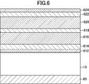
- An infrared reflective substrate 600 which is another embodiment of the present invention, includes an infrared reflective layer including three metal layers.
- the infrared reflective layer 600 includes three metal layers, which makes it possible to design complicated optical properties.
- the infrared reflective substrate 600 shown in FIG. 6 includes a substrate and an infrared reflective layer on the substrate, but the infrared reflective layer is formed of a first metal oxide layer 612, a first metal, in order from the substrate side. It comprises a layer 614, a second metal oxide layer 616, a second metal layer 618, a third metal oxide layer 620, a third metal layer 622 and a fourth metal oxide layer 624.
- the present embodiment includes three metal layers, the present invention includes a metal layer and a metal oxide layer in the same manner as the structure including four or more metal layers and three metal layers. It may be prepared alternately.
- the refractive index (material) and thickness of each layer can be adjusted to make the transmittance of visible light with a wavelength of 600 nm or less 50% or more, more preferably 55% or more, 60% or more is still more preferable.
- the transmittance between 450 nm and 550 nm is preferably 55% or more, more preferably 60% or more, still more preferably 65% or more, and most preferably 70% or more.
- the type and thickness of each layer are adjusted so that the reflectance is increased from the wavelength of 600 nm to the wavelength of 700 nm.
- the slope of reflectance (dR 700-600 (% / nm)) is at least 0.12, preferably at least 0.15, preferably between 0.20 nm and 700 nm. The above is more preferable, and 0.25 or more is still more preferable.
- the metals and metal oxides described in connection with the infrared reflective substrate 500 can be used. Moreover, you may use an adhesive layer, a protective film, and a hard-coat layer as needed like the infrared reflective substrate 500.
- FIG. 1 For the metal layer and the metal oxide layer of the infrared reflective substrate 600, the metals and metal oxides described in connection with the infrared reflective substrate 500 can be used. Moreover, you may use an adhesive layer, a protective film, and a hard-coat layer as needed like the infrared reflective substrate 500. FIG.
- the infrared reflective substrate which is another embodiment of the present invention includes an infrared reflective layer in which two or more types of organic resins are combined in a multilayer.
- the infrared reflective substrate comprises a substrate and an infrared reflective layer on the substrate, but the infrared reflective layer alternately comprises two organic resins having different refractive indices.
- the infrared reflective layer comprises a plurality of first-type organic layers and a plurality of second-type organic layers alternately, and the two types of resin laminates each having a thickness gradually reduced from the substrate side Have multiple bodies.
- the second type organic layer has the same thickness as the first type organic layer immediately below it, and the plurality of first type organic layers and the plurality of second type organic layers are It is getting thinner gradually from the material side.
- the infrared reflective layer in the present embodiment forms a second-type organic substance layer of the same thickness on the main surface of the first-type organic substance layer, and further reduces the first-type organic substance layer by a predetermined thickness. Then, a second type organic substance layer of the same thickness is formed on the second type resin layer, and the same is repeated to form a two-type resin laminate. Furthermore, the infrared reflective substrate is formed by stacking a plurality of the two-type resin laminates.
- the transmittance of visible light with a wavelength of 600 nm or less 50% or more, 55% or more. Is more preferable, and it is more preferable to make it 60% or more.
- the transmittance between 450 nm and 550 nm is preferably 55% or more, more preferably 60% or more, still more preferably 65% or more, and most preferably 70% or more.
- the reflectance increases from 600 nm toward the long wavelength side.
- the slope of reflectance (dR 700-600 (% / nm)) is at least 0.12, preferably at least 0.15, preferably between 0.20 nm and 700 nm. The above is more preferable, and 0.25 or more is still more preferable.
- the thickness of the two-type resin laminate varies depending on the required optical properties and the material to be used, but for example, in the thickest layer, 180 nm to 240 nm is preferable, 190 nm to 230 nm is more preferable, and 200 nm to 220 nm is more preferable. In the thinnest layer, 120 nm to 180 nm is preferable, 130 nm to 170 nm is more preferable, and 140 nm to 160 nm is more preferable.
- the amount of change in thickness of the first and second organic layers is preferably 1 nm to 20 nm, more preferably 2 nm to 10 nm, and still more preferably 3 nm to 7 nm.
- the number of layers of the first resin layer and the second resin layer included in each two-type resin laminate is preferably 5 to 30, more preferably 8 to 20, and still more preferably 10 to 15.
- the number of laminates of the two resin laminates provided in the infrared reflective substrate is preferably 10 or more, the spectrum of the refractive index and the transmittance can be more precisely defined by increasing the number of layers.
- the number of layers is preferably 15 or more, and more preferably 20 or more. However, from the viewpoint of reducing the manufacturing process of the infrared reflective substrate, 35 layers or less are preferable, and 25 layers or less are more preferable.
- the materials used for the first and second organic substance layers may be two organic substances having different refractive indexes.
- the refractive index is preferably 1.3 to 1.7, and more preferably 1.4 to 1.6.
- the difference in refractive index between the two organic substances is preferably 0.01 to 0.2, and more preferably 0.03 to 0.1.
- polyester resin and polyurethane resin can be used.
- Typical examples of the polyester resin that can be used include polyethylene terephthalate, polypropylene terephthalate, polybutylene terephthalate, polyethylene-2,6-naphthalate, poly-1,4-cyclohexanedimethylene terephthalate, and polyethylene diphenyllate. is there.
- polyethylene terephthalate is preferable because it is inexpensive and can be used in a wide variety of applications.
- a preferable amorphous polyester resin is, for example, one having a structure obtained by polycondensation of a dicarboxylic acid component and a diol component in combination and using at least three or more kinds.
- the amorphous polyester resin may be a mixture of two or more polyester resins as long as it is amorphous.
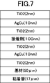
- Example 1 A 2 nm thick titanium oxide (TiO 2 ), 10 nm thick copper (2.5%) silver alloy as an impurity, 2 nm thick on one side of a 50 ⁇ m thick polyethylene terephthalate (PET) film substrate by sputtering Titanium oxide (TiO 2 ) was formed, and a first laminate was formed on the substrate. Then, a photocurable urethane acrylate resin solution was applied onto the first laminate, and after drying, the resin solution was cured by irradiation with ultraviolet rays to form a transparent spacer layer. The amount of the resin solution was adjusted so that the thickness of the transparent spacer layer in which the resin was cured was 100 nm.
- a 17 ⁇ m-thick adhesive layer made of an acrylic adhesive was attached to form a polarizing film laminate of Example 1.
- the layer configuration of the polarizing film laminate of Example 1 is shown in FIG.
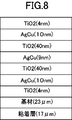
- Example 2 The polarizing film laminate of Example 2 is only that the thickness of the metal layer of the silver alloy of the first laminate and the second laminate is 12 nm and the thickness of the adhesive layer is 70 nm. Unlike the polarizing film laminate of Example 1, the other points are the same.
- Example 3 The polarizing film laminate of Example 3 differs from the polarizing film laminate of Example 1 only in that the thickness of the metal layer of the silver alloy of the first laminate and the second laminate is 12 nm; In terms of points, they are identical.
- Example 4 In the polarizing film laminate of Example 4, the thickness of the metal layer of the silver alloy of the first laminate and the second laminate is 20 nm, and the thickness of the adhesive layer is 70 nm. Unlike the polarizing film laminate of Example 1, the other points are the same.
- Example 5 The polarizing film laminate of Example 5 differs from the polarizing film laminate of Example 1 only in that the thickness of the metal layer of the silver alloy of the first laminate and the second laminate is 15 nm; In terms of points, they are identical.
- Example 6 The polarizing film laminate of Example 6 is different from the polarizing film laminate of Example 1 only in that the thickness of the metal layer of the silver alloy of the first laminate and the second laminate is 20 nm; In terms of points, they are identical.
- Example 7 The polarizing film laminate of Example 7 differs from the polarizing film laminate of Example 1 only in that the thickness of the metal layer of the silver alloy of the first laminate and the second laminate is 25 nm; In terms of points, they are identical.
- the polarizing film laminate of Example 8 comprises three metal layers.
- All silver alloys contain 2.5 wt% of copper as an impurity.
- the adhesive layer similar to Example 1 was bonded on the other side of a PET film base material.
- the laminated structure of Example 8 is shown in FIG.
- the polarizing film laminate of Example 9 includes two types of urethane ester resins, a urethane ester resin (low refractive index resin) having a refractive index of 1.5 and a urethane ester resin (high refractive index resin) having a refractive index of 1.55. , Stacked alternately.
- the thickness of the urethane resin was changed by 5 nm from 210 nm to 150 nm from the side of the pressure-sensitive adhesive layer to be bonded, to create a two-type resin laminate which is a laminate including 13 layers of each material.
- the two-class resin laminate forms a layer of high refractive index resin of 210 nm on the layer of low refractive index resin of 210 nm, and forms a layer of low refractive index resin of 205 nm on it.
- the operation of creating a 205 nm high refractive index resin layer was repeated.
- work of this 2 types of resin laminated body was repeated 20 times, 20 layers of 2 types of resin laminated bodies were accumulated, and the polarizing film laminated body of Example 9 was created.
- Comparative Example 1 A polarizing film laminate of Comparative Example 1 was produced in the same manner as in Example 1 except that the thickness of the adhesive layer was 50 nm.
- Comparative Example 2 A 3 nm thick iron-chromium-nickel composite oxide layer, a 20 nm thick copper layer and a 3 nm thick iron layer by sputtering on one side of a first substrate constituted by a 24 ⁇ m thick PET film A chromium-nickel complex oxide layer was formed in this order.
- a 2.9 ⁇ m thick adhesive composed of a urethane-based adhesive solution is formed on one surface of a second base composed of a PET film having a thickness of 24 ⁇ m different from the first base. It apply
- the polarizing film laminate of Comparative Example 3 includes three metal layers.
- a silver alloy and titanium oxide with a thickness of 4 nm were formed in this order. All silver alloys contain 2.5 wt% of copper as an impurity.
- the adhesive layer similar to Example 1 was bonded on the other side of a PET film base material.
- the polarizing film laminate of Example 4 was composed of a urethane ester resin (low refractive index resin) having a refractive index of 1.5 and a urethane ester resin (high refractive index resin) having a refractive index of 1.55.
- Two types of urethane ester resin were alternately laminated and created.
- the thickness of the urethane resin was changed by 5 nm from 175 nm to 115 nm from the side of the pressure-sensitive adhesive layer to be laminated, to create an alternately arranged laminate which is a laminate of 13 layers.
- positioning laminated body was repeated 20 times, 20 layers of alternating laminated bodies were accumulated, and the polarizing film laminated body of Example 9 was produced.
- each layer constituting the infrared reflection layer is obtained by processing a sample by a focused ion beam (FIB) method using a focused ion beam processing and observation apparatus (product name "FB-2100” manufactured by Hitachi, Ltd.), and its cross section It was determined by observation with a field emission type transmission electron microscope (manufactured by Hitachi, Ltd., product name "HF-2000").
- the thickness of the hard coat layer formed on the substrate and the thickness of the transparent protective layer are visible light when light is incident from the measurement target side using an instantaneous multiphotometric system (product name “MCPD 3000” manufactured by Otsuka Electronics Co., Ltd.) It calculated by calculation from the interference pattern of the reflectance of
- VLT visible light transmittance
- U-4100 manufactured by Hitachi High-Technologies
- an average value of reflectances of 575 nm, 600 nm and 625 nm is used as a reflectance (R 600 ) of wavelength 600 nm
- an average value of reflectances of 675 nm, 700 nm and 725 nm is used as a reflectance (R 700 ) of wavelength 700 nm. It was.
- the solar radiation transmittance ⁇ e and the solar radiation reflectance ee were measured using a spectrophotometer (product name "U-4100” manufactured by Hitachi High-Technologies), and the shielding coefficient (SC) was measured according to JIS A 5759-2008 (building window glass film) A method. ) was calculated.
- the visible light transmittance can be increased by increasing the shielding coefficient (ie, by reducing the degree of shielding). That is, since a lot of light can be transmitted by weakening the degree of shielding, both are in a trade-off relationship, and it can be said that it is relatively easy to raise only one level.
- a polarizing film having both at a high level can be said to be a high performance polarizing film. Therefore, the value of 160 ⁇ SC-12 was calculated and VLTs were compared. The case where VLT is equal to or greater than 160 ⁇ SC-12 was described as “good”, and the case where VLT was less than the value was described as “good”. Further, FIG.
- FIG. 10 shows a graph in which the abscissa represents the shielding coefficient and the ordinate represents VLT.
- the slope of the reflectance between the wavelength 600 nm and the wavelength 700 nm is 0.12 or more, and the visible light absorption rate is less than 30%. It is. Therefore, all of Examples 1 to 9 have a high visible light transmittance and a low shielding coefficient, and the balance between the visible light transmittance and the shielding coefficient is good. As a result, the slope of reflectance is high and the reflectance in near infrared rays is high, so the shielding coefficient is low, while the reflectance in the visible light region is low and the absorptivity of visible light is low. It is because the transmittance becomes high.
- the visible light top wavelength is at a position distant from both ends in the visible light region, that is, 400 nm and 700 nm. It is present and has high visible light transmission.
- Comparative Example 1 Comparative Example 3 and Comparative Example 4, the slope of the reflectance is smaller than 0.12, and the balance between the visible light transmittance and the shielding coefficient is deteriorated.
- 435 nm is the top wavelength of the visible light transmittance, and the transmittance is low in the entire visible light region.
- Comparative Example 4 since the slope of the reflectance is 0.00, the balance between the visible light transmittance and the shielding coefficient is poor, and the value of 160 ⁇ SC-12 is 122, which is visible light. The transmittance is significantly over 92%.
- Comparative Example 2 although the slope of reflectance has a high value of 0.16, the visible light absorptivity is as high as 41%, so the visible light transmittance is low, and the balance between the visible light transmittance and the shielding coefficient Is getting worse.
- Example 1 The transmission, absorption and reflection spectra of 350 nm to 800 nm of Example 1 are shown in FIG. 9a, and the similar spectrum of Comparative Example 1 is shown in FIG. 9b.
- the reflectance is 10% at a wavelength of 600 nm, and while it is low, it increases to nearly 30% at a wavelength of 700 nm, and the slope of the reflectance is large at a wavelength of 600 nm and a wavelength of 700 nm.
- Comparative Example 1 the reflectance is gradually increased from the wavelength of 400 nm to the long wavelength side. Therefore, the shielding coefficient is low at visible light transmittance and remains at 56%.
- FIG. 10a shows the transmission, absorption and reflection spectra of 400 nm to 900 nm of Example 9, and FIG. 10b shows a similar spectrum of Comparative Example 4.
- the reflectance is 10% or less at a wavelength of 600 nm, and is low while it exceeds 40% at a wavelength of 700 nm, and the slope of the reflectance becomes large between the wavelength of 600 nm and the wavelength of 700 nm.
- Comparative Example 4 the reflectance is less than 10% at any of the wavelengths of 600 nm and 700 nm. Then, on a longer wavelength side than near 750 nm, the slope of the reflectance becomes larger, and exceeds 40% at a wavelength of around 850 nm.
- the shielding coefficient of Comparative Example 4 is extremely high and is 0.84.
- the visible light transmittance of Comparative Example 4 is higher than that of Example 9, it is improved by only 2% and 92% of Comparative Example 4 to 90% of Example 9. This is because, at around 700 nm, the weighting factor is low, so even if the transmittance at around 700 nm is increased, the rate of increase in the overall visible light transmittance is limited.
- FIG. 11 is a graph showing the relationship between the shielding coefficient and the visible light transmittance in the example and the comparative example.
- the horizontal axis is the shielding coefficient
- the vertical axis is the visible light transmittance. Examples 1 and 8 are shown as one point because the shielding coefficient and the visible light transmittance are the same value.
- the condition VLT ⁇ 160 ⁇ SC-12 is satisfied.
- the comparative example such a condition is not satisfied.
- DESCRIPTION OF SYMBOLS 100 infrared reflective substrate 10 transparent base material 20 infrared reflective layer 50 window glass 60 adhesive layer 500 infrared reflective layer 500 510 first stacked body 512 first metal oxide layer 514 first metal layer 516 second metal oxide layer 530 transparent spacer layer 550 second stacked body 552 third metal oxide layer 554 second Metal layer 556 fourth metal oxide layer 600 infrared reflective substrate 612 first metal oxide layer 614 first metal layer 616 second metal oxide layer 618 second metal layer 620 third metal oxide layer 622 third metal layer 624 fourth metal oxide layer
Abstract
Provided is an infrared ray-reflective substrate that features both high visible light transmittance and high heat-shielding property. This infrared ray-reflective substrate is provided with a transparent base material and an infrared reflective layer, wherein the visible light absorption rate of the infrared ray-reflective substrate is at most 0.3, and the slope of the reflectivity of the infrared ray-reflective substrate between 600 nm and 700 nm is at least 0.12.
Description
本発明は、透明基材上に赤外線反射層の薄膜を備える赤外線反射基板に関する。
The present invention relates to an infrared reflective substrate comprising a thin film of an infrared reflective layer on a transparent substrate.
従来より、ガラスやフィルム等の基材上に赤外線反射層を備える赤外線反射基板が知られている。このような赤外線反射基板は、例えば、基材をガラスとして、その室内側に形成された赤外線反射層と窓ガラスが一体になって、又は、フィルムを基材として、窓ガラスの室内側に貼られることによって、外部から室内へと入射する太陽光等の近赤外線を反射して、遮熱効果を奏する。もっとも窓ガラス以外にもショーケースなど、外部からの光を遮断する必要があれば他の用途に用いることもできる。
BACKGROUND OF THE INVENTION An infrared reflective substrate provided with an infrared reflective layer on a substrate such as glass or film is conventionally known. Such an infrared reflective substrate is made, for example, by using a glass as a base material, the infrared reflective layer formed on the indoor side thereof and the window glass integrally, or using a film as a base on the indoor side of the window glass As a result, near infrared rays such as sunlight which are incident from the outside into the room are reflected to provide a heat shielding effect. Besides window glass, it can also be used for other applications such as showcases if it is necessary to block external light.
このような赤外線反射基板においては、遮熱性は、高い程好ましいと言えるが、遮熱性を高めると、可視光の透過率が低下してしまい、内部からの視認性が悪化する。すなわち、従来技術であっても、光の透過率を下げれば、遮熱性を高めることができるが、このように透過率を下げて、遮熱性を高めると、可視光透過率も下がってしまう。このため、近年、高い遮光性と可視光透過率を両立することが、望まれている。
In such an infrared reflective substrate, although it is preferable that the heat shielding property is as high as possible, when the heat shielding property is enhanced, the transmittance of visible light is lowered and the visibility from the inside is deteriorated. That is, even if it is a prior art, although the heat insulation can be improved if the light transmittance is lowered, the visible light transmittance will also be lowered if the light transmission is enhanced by lowering the transmittance in this way. For this reason, in recent years, it has been desired to simultaneously achieve high light shielding properties and visible light transmittance.
例えば、気温が高く、太陽光からの熱線が強い、東南アジアといった赤道付近の地域では、可視光透過率は、40%程度と低くても構わないが、0.25以下の遮熱係数を持つようなより高い遮熱性を持つ赤外線反射基板が求められている。一方で、地域によっては、デザイン性や意匠性の観点から65%以上といった高い可視光透過率を維持したまま、遮熱係数0.5以下の遮熱性が求められることもある。
For example, in areas near the equator such as Southeast Asia where the temperature is high and the heat rays from sunlight are strong, the visible light transmittance may be as low as 40%, but it has a heat shielding coefficient of 0.25 or less There is a need for an infrared reflective substrate having a much higher heat shielding property. On the other hand, depending on the area, a heat shield having a heat shield coefficient of 0.5 or less may be required while maintaining a high visible light transmittance of 65% or more from the viewpoint of design and design.
このような赤外線反射基板として、特許文献1は、二層の金属層を含む赤外線反射フィルムを開示している。かかる赤外線反射フィルムは、高い可視光透過率を有すると共に、低い総太陽熱透過率を有することを目標としている。
As such an infrared reflective substrate, Patent Document 1 discloses an infrared reflective film including two metal layers. Such infrared reflective films are targeted to have high visible light transmission and low total solar heat transmission.
しかしながら、遮熱性と可視光透過率は、トレードオフの関係にあるため、従来、高い遮熱性と可視光透過率を両立することは、困難であった。従来の赤外線反射基板は、例えば、可視光透過率が高く、70%の場合には、遮熱係数は、0.55程度を超えていた。また、可視光透過率が低いもので、40%の赤外線反射基板は、0.35程度を超えていた。実際に、特許文献1に開示の赤外線反射フィルムの実施例1及び2の可視光透過率は、77%及び78%と高いが、日射熱取得率(TSHT)は、55及び53であり、これを遮蔽係数に換算すると、62.5及び60.2という高い値になり、上記実施例1及び2のいずれも、遮熱性が低いことがわかる。
However, since the heat shielding property and the visible light transmittance are in a trade-off relationship, it has conventionally been difficult to simultaneously achieve high heat shielding property and visible light transmittance. The conventional infrared reflective substrate has, for example, a high visible light transmittance, and in the case of 70%, the heat shield coefficient exceeds about 0.55. Moreover, the visible light transmittance was low, and the infrared reflective substrate of 40% exceeded about 0.35. In fact, the visible light transmittances of Examples 1 and 2 of the infrared reflective film disclosed in Patent Document 1 are as high as 77% and 78%, but the solar heat gain rate (TSHT) is 55 and 53. When converted to a shielding coefficient, the values are as high as 62.5 and 60.2, and it is understood that the heat shielding properties are low in any of the above-described Examples 1 and 2.
本発明が解決すべき課題は、高い可視光透過率と、高い遮熱性を兼ね備える赤外線反射基板を提供することにある。
The problem to be solved by the present invention is to provide an infrared reflective substrate that has both high visible light transmittance and high heat shielding properties.
従来の赤外線反射基板は、高い遮熱性を有していても、例えば、図9bのスペクトルから明らかなように、可視光領域において反射率が高く、その分、可視光透過率が低くなるとい欠点を有していた。また、図10bにスペクトル示される従来の赤外線反射フィルムは、可視光の波長領域が一般に、400nmから700nmであることを考慮して、波長700nm付近まで、反射率を抑えて、透過率を高くし、750nm付近から長波長側にかけて、光の反射率が高まるという反射特性を有していた。しかし、反射率を特定の波長から急激に高くなるように、赤外線反射基板を設計することは、困難である。そのため、750nm付近から反射率が高まるように赤外線反射基板を設計しても、近赤外領域では反射率が十分高まらず、近赤外光の多くは、赤外線反射基板を透過してしまう。その結果、近赤外光が透過することにより、赤外線反射基板の遮熱性が低下していた。
Even if the conventional infrared reflective substrate has high heat shielding properties, for example, as is apparent from the spectrum of FIG. 9b, the reflectance is high in the visible light region, and the visible light transmittance is correspondingly low. Had. Also, in the conventional infrared reflective film shown in the spectrum in FIG. 10b, in consideration of the fact that the wavelength region of visible light is generally 400 nm to 700 nm, the reflectance is suppressed to a wavelength of around 700 nm to increase the transmittance. In the vicinity of 750 nm to the long wavelength side, it had a reflection characteristic that the light reflectance increased. However, it is difficult to design an infrared reflective substrate so that the reflectance rises rapidly from a specific wavelength. Therefore, even if the infrared reflective substrate is designed so that the reflectance increases from around 750 nm, the reflectance does not sufficiently increase in the near infrared region, and most of the near infrared light passes through the infrared reflective substrate. As a result, the thermal insulation of the infrared reflective substrate is reduced by the transmission of near infrared light.
一方で、人間の目の感度は、可視光領域内でも波長に応じて異なり、均一ではない。例えば、可視光領域内でも、550nm付近の波長を持つ光と、700nm付近の波長を持つ光に対する人間の目の感度は、可視光領域の中心付近の波長を持つ光に対する感度よりも低い。そのため、人間が実際に感じる明るさに対応するように、可視光透過率の算出では、目の感度に応じて波長ごとに定められる重課係数を、実際に透過した光の割合に対して乗算して算出される。図1は、可視光透過率を算出するための重課係数を示すグラフである。図1では、横軸が、波長を示し、縦軸が、重課係数を示す。図1によると、550nmの波長においてもっとも重課係数が高く、10弱の値を示すが、650nmから700nmの波長の範囲では、重課係数は、1以下になる。
On the other hand, the sensitivity of the human eye varies depending on the wavelength even within the visible light range and is not uniform. For example, even in the visible light region, the sensitivity of the human eye to light having a wavelength near 550 nm and light having a wavelength near 700 nm is lower than the sensitivity to light having a wavelength near the center of the visible light region. Therefore, in order to correspond to the brightness actually felt by humans, in the calculation of the visible light transmittance, the weight ratio coefficient determined for each wavelength according to the sensitivity of the eye is multiplied by the ratio of the light actually transmitted. Calculated. FIG. 1 is a graph showing a weighting factor for calculating the visible light transmittance. In FIG. 1, the horizontal axis indicates the wavelength, and the vertical axis indicates the weighting factor. According to FIG. 1, the heavy duty coefficient is the highest at a wavelength of 550 nm and exhibits a value of less than 10. However, in the wavelength range of 650 nm to 700 nm, the heavy duty coefficient is 1 or less.
可視光領域内であっても長波長境界付近では、目の感度が低く可視光透過率の重課係数が低い点を鑑み、可視光領域内の長波長側において、反射率の傾きを大きくすることによって、可視光透過率に与える影響を抑えつつ、近赤外光の反射率を高められることに基づき、本発明の赤外線反射基板は、高い可視光透過率と低い遮熱係数を兼ね備えることができる。
In view of the low sensitivity of the eye and low cohesion coefficient of visible light transmittance near the long wavelength boundary even in the visible light region, increase the slope of the reflectance on the long wavelength side in the visible light region Thus, the infrared reflective substrate of the present invention can have both high visible light transmittance and low heat shielding coefficient based on the fact that the reflectance of near infrared light can be increased while suppressing the influence on visible light transmittance. it can.
本発明は、一態様において、透明基材と、赤外線反射層とを備える赤外線反射基板であって、前記赤外線反射基板の可視光吸収率は、0.3以下であり、前記赤外線反射基板の700nmと600nmの反射率の傾きdR700-600が0.12以上であり、前記反射率の傾きdR700-600(%/nm)は、600nmの波長における前記透明基材側からの反射率をR600(%)とし、前記赤外線反射フィルムの700nmの波長における前記透明基材側からの反射率をR700(%)とすると、dR700-600=(R700-R600)/100(nm)で表されることを特徴とする赤外線反射基板を提供する。
The present invention is, in one aspect, an infrared reflective substrate comprising a transparent substrate and an infrared reflective layer, wherein the visible light absorptivity of the infrared reflective substrate is 0.3 or less, and 700 nm of the infrared reflective substrate and 600nm and the slope dR 700-600 of 0.12 or more reflectivity of the slope dR 700-600 (% / nm) of the reflectance, the reflectance from the transparent substrate side at a wavelength of 600nm R Assuming that 600 (%) and the reflectance from the transparent substrate side at a wavelength of 700 nm of the infrared reflective film is R 700 (%), dR 700-600 = (R 700- R 600 ) / 100 (nm) And an infrared reflective substrate characterized by
前記反射率R600は、10%以上かつ60%以下であることが好ましい。波長600nmにおける反射率を低くすることにより、可視光透過率を高くすることが可能だからである。また、前記反射率R700は、25%以上かつ85%以下であることが好ましい。波長700nmにおける反射率を高めることで、可視光透過率に対する影響を低く維持しつつ、遮蔽係数を低下させることが可能となるからである。また、波長600nmの反射率に対する波長700nmの反射率の比率を1.2以上にすることが好ましい。該反射率の比率を高くすることで、偏光フィルム積層体は、一層高い水準で可視光透過率及び遮蔽係数を両立することができる。可視光透過率トップ波長が、450nmから650nmまでの間にすることにより、可視光透過率を高めることができる。また、透明基材は、フィルムであり、前記透明基材の赤外線反射層を備える面とは、逆側の面に、粘着剤層を備えるようにしてもよいし、透明基材をガラスにしてもよい。前記赤外線反射基板はさらに、赤外線反射層上に、透明保護フィルムを備えるようにして、耐久性を向上させることができる。
The reflectance R 600 is preferably 10% or more and 60% or less. This is because the visible light transmittance can be increased by reducing the reflectance at a wavelength of 600 nm. Further, the reflectance R 700 is preferably 25% or more and 85% or less. By increasing the reflectance at a wavelength of 700 nm, it is possible to reduce the shielding coefficient while keeping the influence on the visible light transmittance low. Moreover, it is preferable to make the ratio of the reflectance of wavelength 700 nm with respect to the reflectance of wavelength 600 nm 1.2 or more. By increasing the ratio of the reflectance, the polarizing film laminate can achieve both the visible light transmittance and the shielding coefficient at a higher level. The visible light transmittance can be increased by setting the visible light transmittance top wavelength between 450 nm and 650 nm. The transparent substrate is a film, and an adhesive layer may be provided on the surface opposite to the surface of the transparent substrate provided with the infrared reflective layer, or the transparent substrate is made of glass. It is also good. The infrared reflective substrate can be further provided with a transparent protective film on the infrared reflective layer to improve the durability.
可視光透過率(VLT)と、遮蔽係数(SC)は、光の透過量(透過率)を減らせば、遮熱係数が低くなることから、トレードオフの関係にあるところ、両パラメータを考慮した赤外線反射フィルムの特性は例えば、VLT(%)-160×SCによって表される。かかる数式は、可視光透過率を1%犠牲にすれば、概ね遮蔽係数を160分の1低下させることが可能であることを根拠とする。本発明の赤外線反射基板は、一態様として、VLT(%)-160×SCが-12以上であるとの特性を備えてもよい。また、当該値は、0以上とすることがより好ましく、10以上とすることがより好ましく、15以上とすることが一層好ましい。また、耐久性といった他の要素を考慮して、該パラメータを20以下としても良いし、17以下としてもよい。
The visible light transmittance (VLT) and the shielding coefficient (SC) are in a trade-off relationship because the heat shielding coefficient decreases as the light transmission amount (transmission) decreases. Both parameters are considered The property of the infrared reflective film is represented by, for example, VLT (%)-160 × SC. This equation is based on the fact that it is possible to reduce the shielding coefficient by approximately 160 by approximately sacrificing the visible light transmittance by 1%. The infrared reflective substrate of the present invention may have, as one aspect, a characteristic that VLT (%) − 160 × SC is −12 or more. Further, the value is more preferably 0 or more, more preferably 10 or more, and still more preferably 15 or more. Further, in consideration of other factors such as durability, the parameter may be 20 or less, or 17 or less.
本発明の赤外線反射基板は、高い可視光透過率と、低い遮熱係数を併せ持つ。
The infrared reflective substrate of the present invention has both high visible light transmittance and low heat shielding coefficient.
図2は、本発明の実施形態となる赤外線反射基板の構成例を模式的に示す断面図である。図2に示されるように、赤外線反射基板100は、透明基材10の一主面上に、赤外線反射層20を備える。本実施形態においては、赤外線反射層20は、透明基材10に直接接しているが、間に別の層を備えてもよい。例えば、耐久性を高めるために、赤外線反射層20と透明基材10との間に、アンダーコート層を設けてもよい。また、赤外線反射層の上面すなわち、透明基材10とは逆側の主面に、赤外線反射層10を保護するための透明保護フィルム(図示せず。)を設けてもよい。
FIG. 2 is a cross-sectional view schematically showing an example of the configuration of the infrared reflective substrate according to the embodiment of the present invention. As shown in FIG. 2, the infrared reflective substrate 100 includes an infrared reflective layer 20 on one main surface of the transparent substrate 10. In the present embodiment, the infrared reflective layer 20 is in direct contact with the transparent substrate 10, but may have another layer in between. For example, an undercoat layer may be provided between the infrared reflective layer 20 and the transparent substrate 10 in order to enhance the durability. In addition, a transparent protective film (not shown) for protecting the infrared reflective layer 10 may be provided on the upper surface of the infrared reflective layer, that is, the main surface on the opposite side to the transparent substrate 10.
図3は、赤外線反射基板の機能を概略的に説明するために用いられ、赤外線反射の使用形態の一例の断面を模式的に示している。当該使用形態において、赤外線反射基板の透明基材は、フィルム基材である。赤外線反射基板100の透明基材側の主面が、粘着剤層60等を介して、建物や自動車の窓ガラス50の室内側に貼り合わされて用いられる。図3に示されるように、赤外線反射基板100は、屋外からの可視光(VIS)を透過して室内に導入すると共に、屋外からの近赤外線(NIR)を赤外線反射層20で反射する。近赤外線反射により、太陽光等に起因する室外から室内への入射する熱線が抑制される(遮熱効果が発揮される)ため、夏場の冷房効率を高めることができる。
FIG. 3 is used to schematically explain the function of the infrared reflective substrate, and schematically shows a cross section of an example of the usage of infrared reflectance. In the use form, the transparent substrate of the infrared reflective substrate is a film substrate. The main surface on the transparent base material side of the infrared reflective substrate 100 is bonded to the indoor side of the window glass 50 of a building or an automobile via the adhesive layer 60 or the like. As shown in FIG. 3, the infrared reflection substrate 100 transmits visible light (VIS) from the outside and introduces it into the room, and reflects near infrared light (NIR) from the outside by the infrared reflection layer 20. The near-infrared reflection suppresses heat rays incident from the outside to the room due to sunlight and the like (a heat shielding effect is exhibited), so that the cooling efficiency in summer can be enhanced.
図4は、本発明の実施形態となる赤外線反射基板100の、基材側から入射する光の透過率及び反射率の典型例を示すグラフである。横軸は、波長(nm)であり、縦軸は、透過率(%)及び反射率(%)である。図4においては、JIS A5759-2008(建築窓ガラスフィルム)に準じた単板ガラスに赤外線反射基板が貼られている。なお、赤外線反射基板に入射する光は、透過、反射及び吸収の何れかの帰趨をたどるため、100%から、透過率及び反射率を減じた値が、吸収率となる。
FIG. 4 is a graph showing a typical example of the transmittance and reflectance of light incident from the base material side of the infrared reflective substrate 100 according to the embodiment of the present invention. The horizontal axis is wavelength (nm), and the vertical axis is transmittance (%) and reflectance (%). In FIG. 4, the infrared reflective substrate is attached to a single sheet glass conforming to JIS A 5759-2008 (architectural window glass film). In addition, since the light which injects into an infrared reflectiveness board | substrate follows any one of transmission, reflection, and absorption, the value which reduced the transmittance | permeability and the reflectance from 100% becomes an absorptivity.
赤外線反射基板100は、可視光領域の内の短波長側に当たる400nmから550nmにおいては、透過率が、70%程度と高い一方で、反射率は、10%程度と低い。550nm付近から長波長側にかけて、反射率が高くなり、可視光領域の長波長側境界付近となる700nmでは、反射率は、50%を超える。そして、可視光領域よりも長波長となる近赤外光領域では、可視光領域に近い波長である700nmから800nmにおいて、赤外線反射基板100は、50%を超える反射率を持つ。このように、近赤外光領域の中でも可視光領域に近い700nmから800nmでありながら、50%を超える高い反射率を持つ理由は、600nmから700nmの波長領域において、反射率の傾きが、高いことにある。そのため、赤外線反射基板100は、可視光領域付近の近赤外光領域であっても、光の反射率が高いことから、遮熱性が高く、遮熱係数は、0.50である。
The infrared reflective substrate 100 has a high transmittance of about 70% and a low reflectance of about 10% at 400 nm to 550 nm, which corresponds to the short wavelength side in the visible light region. The reflectance increases from around 550 nm to the long wavelength side, and the reflectance exceeds 50% at 700 nm near the long wavelength side boundary of the visible light region. Then, in the near infrared light region having a longer wavelength than the visible light region, the infrared reflective substrate 100 has a reflectance of over 50% at 700 nm to 800 nm which is a wavelength close to the visible light region. As described above, the reason why the near infrared light region has high reflectance of over 50% while being 700 nm to 800 nm close to the visible light region is that the slope of the reflectance is high in the wavelength region of 600 nm to 700 nm It is. Therefore, the infrared reflective substrate 100 has a high heat shielding property and a heat shielding coefficient of 0.50 because the light reflectance is high even in the near infrared light area near the visible light area.
本願においては、反射率の傾きは、数1に記載される定義に基づいて定められる。

λ:波長(nm)(upperは、長波長側、lowerは、短波長側の波長であることを示す。)Rλ:波長λにおける反射率(%)
dRλupper-λlower:波長λupperと波長λlowerとの間における反射率の傾き(%/nm) In the present application, the slope of reflectance is determined based on the definition described in Equation 1.
λ: wavelength (nm) (upper indicates long wavelength side, lower indicates wavelength on short wavelength side) R λ : reflectance at wavelength λ (%)
dR λ upper-λ lower : slope of reflectance between wavelength λ upper and wavelength λ lower (% / nm)
dRλupper-λlower:波長λupperと波長λlowerとの間における反射率の傾き(%/nm) In the present application, the slope of reflectance is determined based on the definition described in Equation 1.
dR λ upper-λ lower : slope of reflectance between wavelength λ upper and wavelength λ lower (% / nm)
赤外線反射基板100は、波長領域600nmから700nmにかけて、反射率が高くなるように設計されているため、透過率は低下する。しかしながら、図1に示されるように、波長600nmから700nmでは、可視光透過率算出における重課係数が低いので、可視光透過率に与える影響が小さい。そのため、赤外線反射基板100は、遮熱性が高いにも関わらず、可視光透過率は、68%と高い値を有する。
The infrared reflective substrate 100 is designed to have a high reflectance in the wavelength range of 600 nm to 700 nm, so the transmittance is reduced. However, as shown in FIG. 1, at wavelengths of 600 nm to 700 nm, since the heavy duty coefficient in the visible light transmittance calculation is low, the influence on the visible light transmittance is small. Therefore, the visible light transmittance of the infrared reflective substrate 100 has a high value of 68% despite the high thermal insulation.
以下、各層の構成や材料等の好ましい実施形態について、順に説明する。
Hereinafter, preferred embodiments of the configuration, materials and the like of each layer will be described in order.
[透明基材]
透明基材10としては、可視光線透過率が80%以上のものが好適に用いられる。なお、可視光線透過率は例えば、JIS A5759-2008(建築窓ガラスフィルム)に準じて測定される。 [Transparent base material]
As thetransparent substrate 10, those having a visible light transmittance of 80% or more are suitably used. The visible light transmittance is measured, for example, according to JIS A 5759-2008 (Building Window Glass Film).
透明基材10としては、可視光線透過率が80%以上のものが好適に用いられる。なお、可視光線透過率は例えば、JIS A5759-2008(建築窓ガラスフィルム)に準じて測定される。 [Transparent base material]
As the
透明基材10の厚みは、特に限定されないが、典型的には10μmから10mm程度である。透明基材としては、ガラス板や可撓性の透明樹脂フィルム等が用いられる。赤外線反射基板の生産性を高め、かつ窓ガラス等へ赤外線反射基板を貼り合わせる際の施工を容易とする観点からは、透明基材10には、可撓性の透明樹脂フィルムが好適に用いられる。透明基材として透明樹脂フィルムが用いられる場合、その厚みは10μm~300μm程度の範囲が好適であり、100μm以下が、好ましく、50μm以下が一層好ましく、40μm以下がより一層好ましい。また、透明基材10上に、金属層や金属酸化物層等が形成される際に、高温での加工が行われる場合があるため、透明樹脂フィルム基材を構成する樹脂材料は、耐熱性に優れるものが好ましい。透明樹脂フィルム基材を構成する樹脂材料としては、ポリエチレンテレフタレート(PET)、ポリエチレンナフタレート(PEN)、ポリエーテルエーテルケトン(PEEK)、ポリカーボネート(PC)等が挙げられる。
The thickness of the transparent substrate 10 is not particularly limited, but typically about 10 μm to 10 mm. A glass plate, a flexible transparent resin film, etc. are used as a transparent base material. A flexible transparent resin film is suitably used as the transparent substrate 10 from the viewpoint of enhancing the productivity of the infrared reflective substrate and facilitating the installation when bonding the infrared reflective substrate to a window glass or the like. . When a transparent resin film is used as the transparent substrate, the thickness thereof is preferably in the range of about 10 μm to 300 μm, preferably 100 μm or less, more preferably 50 μm or less, and still more preferably 40 μm or less. Moreover, when a metal layer, a metal oxide layer, etc. are formed on the transparent base material 10, since processing at high temperature may be performed, the resin material which comprises a transparent resin film base material is heat resistance. Those which are excellent in Examples of the resin material constituting the transparent resin film substrate include polyethylene terephthalate (PET), polyethylene naphthalate (PEN), polyetheretherketone (PEEK), polycarbonate (PC) and the like.
透明基材10が、透明樹脂フィルム基材である場合、赤外線反射基板の機械的強度を高める等の目的で、透明フィルムに加えて、該透明フィルムの表面に硬化樹脂層を備えるものが好適に用いられる。また、透明フィルムの赤外線反射層20形成面側に硬化樹脂層を備えることで、赤外線反射層20や、その上に形成され得る透明保護層等の耐擦傷性が高められる傾向がある。硬化樹脂層12は、例えばアクリル系、シリコーン系等の適宜な紫外線硬化型樹脂の硬化被膜を、透明フィルム上に付設する方式等により形成できる。硬化樹脂層としては、硬度の高いものが好適に用いられる。
When the transparent substrate 10 is a transparent resin film substrate, one having a cured resin layer on the surface of the transparent film in addition to the transparent film is preferable for the purpose of, for example, enhancing the mechanical strength of the infrared reflective substrate. Used. Further, by providing the cured resin layer on the side of the transparent film on which the infrared reflective layer 20 is formed, the scratch resistance of the infrared reflective layer 20, the transparent protective layer that can be formed thereon, and the like tends to be enhanced. The cured resin layer 12 can be formed, for example, by a method in which a cured film of an appropriate ultraviolet curable resin such as an acrylic resin or a silicone resin is attached on a transparent film. As the cured resin layer, one having high hardness is suitably used.
透明基材10の赤外線反射層20が形成される面側には、密着性向上等の目的で、コロナ処理、プラズマ処理、フレーム処理、オゾン処理、プライマー処理、グロー処理、ケン化処理、カップリング剤による処理等の表面改質処理が行われてもよい。
Corona treatment, plasma treatment, flame treatment, ozone treatment, primer treatment, glow treatment, saponification treatment, coupling on the side of the transparent substrate 10 on which the infrared reflection layer 20 is formed, for the purpose of improving adhesion, etc. Surface modification treatment such as treatment with an agent may be performed.
[粘着剤層]
透明基材10が、樹脂フィルム基剤の場合には、透明基材10の赤外線反射層20が形成される面と反対側の面に、赤外線反射基板と窓ガラス等との貼り合せに用いるための粘着剤層60等が付設されてもよい。粘着剤層60は、可視光線透過率が高く、透明基材10との屈折率差が小さいことが好ましく、例えば、アクリル系の粘着剤(感圧粘着剤)は、光学的透明性に優れ、適度な濡れ性と凝集性と接着性を示し、耐候性や耐熱性等に優れることから、透明フィルム基材に付設される粘着剤層の材料として好適である。 [Pressure-sensitive adhesive layer]
In the case where thetransparent substrate 10 is a resin film base, it is used to bond an infrared reflective substrate to a window glass or the like on the surface of the transparent substrate 10 opposite to the surface on which the infrared reflective layer 20 is formed. The pressure-sensitive adhesive layer 60 or the like may be attached. The pressure-sensitive adhesive layer 60 preferably has a high visible light transmittance and a small difference in refractive index from the transparent substrate 10. For example, an acrylic pressure-sensitive adhesive (pressure-sensitive adhesive) is excellent in optical transparency, It is suitable as a material of a pressure-sensitive adhesive layer to be attached to a transparent film substrate because it exhibits appropriate wettability, cohesion and adhesiveness, and is excellent in weather resistance, heat resistance and the like.
透明基材10が、樹脂フィルム基剤の場合には、透明基材10の赤外線反射層20が形成される面と反対側の面に、赤外線反射基板と窓ガラス等との貼り合せに用いるための粘着剤層60等が付設されてもよい。粘着剤層60は、可視光線透過率が高く、透明基材10との屈折率差が小さいことが好ましく、例えば、アクリル系の粘着剤(感圧粘着剤)は、光学的透明性に優れ、適度な濡れ性と凝集性と接着性を示し、耐候性や耐熱性等に優れることから、透明フィルム基材に付設される粘着剤層の材料として好適である。 [Pressure-sensitive adhesive layer]
In the case where the
粘着剤層60は、可視光線の透過率が高く、かつ紫外線透過率が小さいものが好ましい。粘着剤層60の紫外線透過率を小さくすることにより、太陽光等の紫外線に起因する赤外線反射層の劣化を抑制できる。粘着剤層の紫外線透過率を小さくする観点から、粘着剤層は紫外線吸収剤を含有することが好ましい。なお、紫外線吸収剤を含有する透明フィルム基材等を用いることによっても、屋外からの紫外線に起因する赤外線反射層の劣化を抑制できる。粘着剤層の露出面は、赤外線反射基板が実用に供されるまでの間、露出面の汚染防止等を目的にセパレータが仮着されてカバーされることが好ましい。これにより、通例の取扱状態で、粘着剤層の露出面の外部との接触による汚染を防止できる。
The pressure-sensitive adhesive layer 60 preferably has a high visible light transmittance and a low ultraviolet light transmittance. By reducing the ultraviolet light transmittance of the pressure-sensitive adhesive layer 60, it is possible to suppress the deterioration of the infrared reflective layer caused by the ultraviolet light such as sunlight. From the viewpoint of reducing the ultraviolet light transmittance of the pressure-sensitive adhesive layer, the pressure-sensitive adhesive layer preferably contains an ultraviolet light absorber. In addition, degradation of the infrared reflectiveness layer resulting from the ultraviolet-ray from the outdoors can be suppressed also by using the transparent film base material etc. which contain an ultraviolet absorber. The exposed surface of the pressure-sensitive adhesive layer is preferably covered with a separator temporarily attached for the purpose of preventing contamination of the exposed surface until the infrared reflective substrate is put to practical use. Thereby, the contamination by the contact with the exterior of the exposed surface of an adhesive layer can be prevented in a usual handling state.
なお、透明基材10が可撓性フィルムである場合でも、例えば、特許文献2に開示されているように、赤外線反射基板を枠体等に嵌め込んで用いることもできる。当該形態では、透明基材10に粘着剤層60を付設する必要がないため、粘着剤層による遠赤外線の吸収が生じない。そのため、透明基材10として、C=C結合、C=O結合、C-O結合、芳香族環等の官能基の含有量が少ない材料(例えば環状ポリオレフィン)を用いることにより、透明基材10側からの遠赤外線を赤外線反射層20で反射させることができ、赤外線反射基板の両面側に断熱性を付与できる。このような構成は、例えば冷蔵ショーケースや冷凍ショーケース等で特に有用である。
Even when the transparent substrate 10 is a flexible film, for example, as disclosed in Patent Document 2, the infrared reflective substrate can be used by being fitted in a frame or the like. In the said form, since it is not necessary to attach the adhesive layer 60 to the transparent base material 10, absorption of the far-infrared rays by an adhesive layer does not arise. Therefore, by using a material having a small content of functional groups such as C = C bond, C = O bond, C—O bond, and aromatic ring as the transparent substrate 10 (for example, cyclic polyolefin), the transparent substrate 10 can be obtained. Far infrared rays from the side can be reflected by the infrared reflection layer 20, and heat insulation can be imparted to both sides of the infrared reflection substrate. Such a configuration is particularly useful, for example, in a refrigerated showcase or a frozen showcase.
[赤外線反射層]
本発明の実施形態における赤外線反射層20は、波長600nmから波長700nmにかけて光の反射率の傾きが高いものであり、例えば、以下のような実施形態が存在するが、本発明は、これらの形態に限定されるわけではない。 [Infrared reflective layer]
The infraredreflective layer 20 in the embodiment of the present invention has a high light reflectance inclination from a wavelength of 600 nm to a wavelength of 700 nm. For example, the following embodiments exist. It is not necessarily limited to
本発明の実施形態における赤外線反射層20は、波長600nmから波長700nmにかけて光の反射率の傾きが高いものであり、例えば、以下のような実施形態が存在するが、本発明は、これらの形態に限定されるわけではない。 [Infrared reflective layer]
The infrared
<2層の金属層構成>
図5は、本発明の実施形態における赤外線反射層500を示す。図5における赤外線反射層500は、2層の金属層によって、ファブリペロー共振器を形成する。該2層の金属層は、ファブリペロー共振器におけるハーフミラーの役割を果たす。そして、この2層の金属薄膜間に、透明スペーサ層を配置して、特定の波長の光を選択的に透過させ、他の波長の光を反射あるいは干渉・減衰させることにより光が遮蔽される。ファブリペロー共振器では、2層の金属薄膜間にある透明スペーサ層の光学膜厚(屈折率と物理的な膜厚の積)を調整することによって、透過させる光の波長の範囲と、反射させる光の波長の範囲を変更することができる。 <Metal layer configuration of two layers>
FIG. 5 shows an infraredreflective layer 500 in an embodiment of the present invention. The infrared reflective layer 500 in FIG. 5 forms a Fabry-Perot resonator by two metal layers. The two metal layers play the role of a half mirror in a Fabry-Perot resonator. Then, a transparent spacer layer is disposed between the two metal thin films, and light is blocked by selectively transmitting light of a specific wavelength and reflecting, interfering, or attenuating light of other wavelengths. . In the Fabry-Perot resonator, by adjusting the optical film thickness (the product of the refractive index and the physical film thickness) of the transparent spacer layer between the two metal thin films, the range of wavelengths of light to be transmitted and the reflection are made The range of wavelengths of light can be changed.
図5は、本発明の実施形態における赤外線反射層500を示す。図5における赤外線反射層500は、2層の金属層によって、ファブリペロー共振器を形成する。該2層の金属層は、ファブリペロー共振器におけるハーフミラーの役割を果たす。そして、この2層の金属薄膜間に、透明スペーサ層を配置して、特定の波長の光を選択的に透過させ、他の波長の光を反射あるいは干渉・減衰させることにより光が遮蔽される。ファブリペロー共振器では、2層の金属薄膜間にある透明スペーサ層の光学膜厚(屈折率と物理的な膜厚の積)を調整することによって、透過させる光の波長の範囲と、反射させる光の波長の範囲を変更することができる。 <Metal layer configuration of two layers>
FIG. 5 shows an infrared
赤外線反射層500は、基材10側から順に、第1の積層体510、透明スペーサ層530、第2の積層体550を備える。また、第1の積層体510は基材10側から順に、第1の金属酸化物層512、第1の金属層514、第2の金属酸化物層516を備え、第2の積層体は基材10側から順に、第3の金属酸化物層552、第2の金属層554、第4の金属酸化物層556を備える。第1の金属層514と、第2の金属層554が、ハーフミラーの役割を果たす上記2層の金属層に対応する。第1の金属層と、第1の金属酸化物層及び第2の金属酸化物層とは、直接接しているが、金属層の保護のため、あるいは、界面の屈折率差を調節するために、両者の間に他の層を含んでもよい。同様に、第2の金属層と、第3の金属酸化物層及び第4の金属酸化物層とは、直接接しているが、両者の間に他の層を含んでもよい。
The infrared reflective layer 500 includes a first laminate 510, a transparent spacer layer 530, and a second laminate 550 in this order from the substrate 10 side. In addition, the first stacked body 510 includes a first metal oxide layer 512, a first metal layer 514, and a second metal oxide layer 516 in this order from the substrate 10 side, and the second stacked body is a base The third metal oxide layer 552, the second metal layer 554, and the fourth metal oxide layer 556 are provided in order from the material 10 side. The first metal layer 514 and the second metal layer 554 correspond to the two metal layers acting as a half mirror. The first metal layer is in direct contact with the first metal oxide layer and the second metal oxide layer, but for the protection of the metal layer or to adjust the refractive index difference of the interface. And other layers may be included between the two. Similarly, the second metal layer is in direct contact with the third metal oxide layer and the fourth metal oxide layer, but other layers may be included between the two.
<金属層>
金属層514及び554は、赤外線反射の中心的な役割を有する。金属層514及び5554の材料としては、銀、金、銅、アルミニウム等の近赤外線の反射率の高い金属が好ましく用いられる。中でも、積層数を増加させることなく、可視光線透過率と近赤外線反射率を高める観点から、金属酸化物層の間に挟持される金属層として、銀を主成分とする銀合金層が好適に用いられる。銀は高い自由電子密度を有するため、近赤外線・遠赤外線の高い反射率を実現することができ、赤外線反射層20を構成する層の積層数が少ない場合でも、遮熱効果および断熱効果に優れる赤外線反射フィルムが得られる。 <Metal layer>
Metal layers 514 and 554 have a central role in infrared reflection. As a material of the metal layers 514 and 5554, metals having high near infrared reflectance, such as silver, gold, copper, and aluminum, are preferably used. Among them, a silver alloy layer containing silver as a main component is preferably used as a metal layer sandwiched between metal oxide layers from the viewpoint of enhancing visible light transmittance and near infrared reflectance without increasing the number of laminations. Used. Silver has high free electron density, so that high reflectance of near infrared rays and far infrared rays can be realized, and the heat shielding effect and the heat insulating effect are excellent even when the number of laminated layers constituting theinfrared reflection layer 20 is small. An infrared reflective film is obtained.
金属層514及び554は、赤外線反射の中心的な役割を有する。金属層514及び5554の材料としては、銀、金、銅、アルミニウム等の近赤外線の反射率の高い金属が好ましく用いられる。中でも、積層数を増加させることなく、可視光線透過率と近赤外線反射率を高める観点から、金属酸化物層の間に挟持される金属層として、銀を主成分とする銀合金層が好適に用いられる。銀は高い自由電子密度を有するため、近赤外線・遠赤外線の高い反射率を実現することができ、赤外線反射層20を構成する層の積層数が少ない場合でも、遮熱効果および断熱効果に優れる赤外線反射フィルムが得られる。 <Metal layer>
Metal layers 514 and 554 have a central role in infrared reflection. As a material of the metal layers 514 and 5554, metals having high near infrared reflectance, such as silver, gold, copper, and aluminum, are preferably used. Among them, a silver alloy layer containing silver as a main component is preferably used as a metal layer sandwiched between metal oxide layers from the viewpoint of enhancing visible light transmittance and near infrared reflectance without increasing the number of laminations. Used. Silver has high free electron density, so that high reflectance of near infrared rays and far infrared rays can be realized, and the heat shielding effect and the heat insulating effect are excellent even when the number of laminated layers constituting the
金属層514及び554は、銀を75~99.9重量%含有することが好ましい。可視光透過率を高める観点から、金属層15の銀の含有量は、80重量%以上がより好ましく、85重量%以上がさらに好ましく、90重量%以上が特に好ましい。例えば、銀の含有量を96重量%以上とすることで、透過率および反射率の波長選択性を高め、可視光線透過率を高めることができる。金属層514、554における銀の含有量が増加するにしたがって、赤外線反射フィルムの可視光線透過率が高められる傾向がある。
The metal layers 514 and 554 preferably contain 75 to 99.9% by weight of silver. From the viewpoint of enhancing the visible light transmittance, the silver content of the metal layer 15 is more preferably 80% by weight or more, further preferably 85% by weight or more, and particularly preferably 90% by weight or more. For example, by setting the content of silver to 96% by weight or more, the wavelength selectivity of the transmittance and the reflectance can be enhanced, and the visible light transmittance can be enhanced. As the silver content in the metal layers 514, 554 increases, the visible light transmittance of the infrared reflective film tends to be enhanced.
一方で、銀は、水分、酸素、塩素等が存在する環境下に暴露された場合や、紫外光や可視光が照射された場合に、酸化や腐食等の劣化を生じる場合がある。そのため、金属層514、554は、耐久性を向上させる目的で、銀以外の金属を含有する銀合金層であることが好ましい。例えば、金属層514、554は、銀以外の金属を0.1重量%以上含有することが好ましく、0.2重量%以上含有することがより好ましく、0.3重量%以上含有することがさらに好ましい。金属層の耐久性を高める目的で添加される金属としては、パラジウム(Pd),金(Au),銅(Cu),ビスマス(Bi),ゲルマニウム(Ge),ガリウム(Ga)等が好ましい。中でも、銀に高い耐久性を付与する観点から、Pdが最も好適に用いられる。Pd等の添加量を増加させると、金属層の耐久性が向上する傾向がある。一方で、Pd等の添加量が過度に多いと、赤外線反射フィルムの可視光線透過率が低下する傾向がある。そのため、金属層中の銀以外の金属の含有量は、10重量%以下が好ましく、5重量%以下がより好ましく、3重量%以下がさらに好ましく、1重量%以下が特に好ましい。
On the other hand, silver may cause deterioration such as oxidation or corrosion when exposed to an environment in which water, oxygen, chlorine or the like is present, or when irradiated with ultraviolet light or visible light. Therefore, the metal layers 514 and 554 are preferably silver alloy layers containing metals other than silver for the purpose of improving the durability. For example, the metal layers 514 and 554 preferably contain 0.1% by weight or more of a metal other than silver, more preferably 0.2% by weight or more, and further preferably 0.3% by weight or more. preferable. As the metal added for the purpose of enhancing the durability of the metal layer, palladium (Pd), gold (Au), copper (Cu), bismuth (Bi), germanium (Ge), gallium (Ga), etc. are preferable. Among them, Pd is most preferably used from the viewpoint of imparting high durability to silver. When the addition amount of Pd or the like is increased, the durability of the metal layer tends to be improved. On the other hand, when the addition amount of Pd or the like is excessively large, the visible light transmittance of the infrared reflective film tends to decrease. Therefore, 10 weight% or less is preferable, as for content of metals other than silver in a metal layer, 5 weight% or less is more preferable, 3 weight% or less is further more preferable, and 1 weight% or less is especially preferable.
また、金属層は、銀合金に限られるものではなく、例えば、耐久性を高める観点から、金単体又は金を主成分とする金合金を用いてもよい。金合金における金の含有量は、75~99.9重量%含有することが好ましい。特に、可視光透過率を高める観点から、金属層の金の含有量は、80重量%以上がより好ましく、85重量%以上がさらに好ましく、90重量%以上が特に好ましい。また、銀を不純物とすることが好ましく、例えば、銀を1から25重量%含有することが好ましく、10重量%以下がより好ましく、5重量%以下がさらに好ましい。
Further, the metal layer is not limited to a silver alloy, and for example, from the viewpoint of enhancing the durability, a gold simple substance or a gold alloy containing gold as a main component may be used. The content of gold in the gold alloy is preferably 75 to 99.9% by weight. In particular, from the viewpoint of enhancing the visible light transmittance, the content of gold in the metal layer is more preferably 80% by weight or more, still more preferably 85% by weight or more, and particularly preferably 90% by weight or more. In addition, it is preferable to use silver as an impurity, for example, it is preferable to contain 1 to 25% by weight of silver, 10% by weight or less is more preferable, and 5% by weight or less is more preferable.
第1の金属層514と第2の金属層554は、異なる金属であってもよく、例えば、表面に近く、高い耐久性が必要となる第2の金属層を金合金とする一方で、第1の金属層を安価な銀合金としてもよい。
The first metal layer 514 and the second metal layer 554 may be different metals, for example, while the second metal layer close to the surface and requiring high durability is a gold alloy, The metal layer 1 may be an inexpensive silver alloy.
第1の金属層514及び第2の金属層554の膜厚は、金属層がハーフミラーとして機能するように、材料の屈折率等を勘案して適宜に設定される。金属層514、554の膜厚は、4nm~25nmが好ましく、5nm~20nmがより好ましい。
The film thicknesses of the first metal layer 514 and the second metal layer 554 are appropriately set in consideration of the refractive index and the like of the material so that the metal layer functions as a half mirror. The thickness of the metal layers 514 and 554 is preferably 4 nm to 25 nm, and more preferably 5 nm to 20 nm.
金属層514、554の形成方法としては、スパッタ法、真空蒸着法、電子線蒸着法等のドライプロセスが好ましい。中でも、ロールトゥーロール成膜が可能であり、金属酸化物層と共通の成膜方法を採用でき、かつ成膜レートが高いことから、スパッタ法が好ましい。
As a method of forming the metal layers 514 and 554, a dry process such as a sputtering method, a vacuum evaporation method, or an electron beam evaporation method is preferable. Among them, the roll-to-roll film formation is possible, the film formation method common to the metal oxide layer can be adopted, and the film formation rate is high, so the sputtering method is preferable.
<金属酸化物層>
金属酸化物層512、516、552及び556は、金属層との界面における可視光線の反射量を制御して、高い可視光線透過率と、赤外線反射率とを両立させる等の目的で設けられる。また、金属酸化物層は、金属層514、554の劣化を防止するための保護層としても機能し得る。赤外線反射層における反射および透過の波長選択性を高める観点から、金属酸化物層の可視光に対する屈折率は、1.5以上が好ましく、1.6以上がより好ましく、1.7以上がさらに好ましい。 <Metal oxide layer>
The metal oxide layers 512, 516, 552 and 556 are provided for the purpose of achieving both high visible light transmittance and infrared reflectance by controlling the reflection amount of visible light at the interface with the metal layer. The metal oxide layer can also function as a protective layer for preventing deterioration of the metal layers 514 and 554. From the viewpoint of enhancing the wavelength selectivity of reflection and transmission in the infrared reflection layer, the refractive index to visible light of the metal oxide layer is preferably 1.5 or more, more preferably 1.6 or more, and still more preferably 1.7 or more. .
金属酸化物層512、516、552及び556は、金属層との界面における可視光線の反射量を制御して、高い可視光線透過率と、赤外線反射率とを両立させる等の目的で設けられる。また、金属酸化物層は、金属層514、554の劣化を防止するための保護層としても機能し得る。赤外線反射層における反射および透過の波長選択性を高める観点から、金属酸化物層の可視光に対する屈折率は、1.5以上が好ましく、1.6以上がより好ましく、1.7以上がさらに好ましい。 <Metal oxide layer>
The
上記の屈折率を有する材料としては、チタン(Ti),ジルコン(Zr),ハフニウム(Hf),ニオブ(Nb),亜鉛(Zn),アルミニウム(Al),ガリウム(Ga),インジウム(In),タリウム(Tl),錫(Sn)等の金属の酸化物、あるいはこれらの金属の複合酸化物が挙げられる。特に、本発明においては、金属酸化物層512、516、552及び556の材料として、酸化亜鉛を含有する複合金属酸化物が好適に用いられる。また、これらの金属酸化物層は、金属層を保護する機能をも有するため、非晶質であることが好ましい。金属酸化物層が酸化亜鉛を含有する非晶質層である場合、金属酸化物層自体の耐久性が高められると共に、金属層に対する保護層としての作用が増大するため、銀合金からなる金属層の劣化が抑制される。
As materials having the above-mentioned refractive index, titanium (Ti), zircon (Zr), hafnium (Hf), niobium (Nb), zinc (Zn), aluminum (Al), gallium (Ga), indium (In), Examples thereof include oxides of metals such as thallium (Tl) and tin (Sn), or composite oxides of these metals. In particular, in the present invention, a composite metal oxide containing zinc oxide is suitably used as the material of the metal oxide layers 512, 516, 552 and 556. In addition, since these metal oxide layers also have a function of protecting the metal layer, they are preferably amorphous. When the metal oxide layer is an amorphous layer containing zinc oxide, the durability of the metal oxide layer itself is enhanced and the function as a protective layer for the metal layer is increased, so that the metal layer made of a silver alloy Deterioration of the
金属酸化物層512、516、552及び556中の酸化亜鉛の含有量は、金属酸化物の合計100重量部に対して、3重量部以上が好ましく、5重量部以上がより好ましく、7重量部以上がさらに好ましい。酸化亜鉛の含有量が上記範囲であれば、金属酸化物層が非晶質層となりやすく、耐久性が高められる傾向がある。一方、酸化亜鉛の含有量が過度に大きいと、逆に耐久性が低下したり、可視光線透過率が低下する傾向がある。そのため、金属酸化物層512、516、552、556中の酸化亜鉛の含有量は、金属酸化物の合計100重量部に対して、60重量部以下が好ましく、50重量部以下がより好ましく、40重量部以下がさらに好ましい。
The content of zinc oxide in the metal oxide layers 512, 516, 552 and 556 is preferably 3 parts by weight or more, more preferably 5 parts by weight or more, and 7 parts by weight with respect to 100 parts by weight in total of metal oxides. The above is more preferable. When the content of zinc oxide is in the above range, the metal oxide layer tends to be an amorphous layer, and the durability tends to be enhanced. On the other hand, when the content of zinc oxide is excessively large, the durability tends to decrease and the visible light transmittance tends to decrease. Therefore, the content of zinc oxide in the metal oxide layers 512, 516, 552, 556 is preferably 60 parts by weight or less, more preferably 50 parts by weight or less, with respect to 100 parts by weight in total of the metal oxides. Parts by weight or less are more preferred.
酸化亜鉛を含有する複合金属酸化物としては、可視光線透過率、屈折率、耐久性の全てを満足するとの観点から、インジウム-亜鉛複合酸化物(IZO)、亜鉛-錫複合酸化物(ZTO)、インジウム-錫-亜鉛複合酸化物(ITZO)等が好ましい。これらの複合酸化物は、さらにAlやGa等の金属や、これらの金属の酸化物を含有していてもよい。
As the composite metal oxide containing zinc oxide, from the viewpoint of satisfying all of visible light transmittance, refractive index and durability, indium-zinc composite oxide (IZO), zinc-tin composite oxide (ZTO) Indium-tin-zinc complex oxide (ITZO) and the like are preferable. These composite oxides may further contain metals such as Al and Ga, and oxides of these metals.
金属酸化物層512、516、552、556の厚みは、赤外線反射層が、可視光線を透過し近赤外線を選択的に反射するように、材料の屈折率等を勘案して適宜に設定される。金属酸化物層512、516、552、556の厚みは、例えば、3nm~80nm、好ましくは3nm~50nm、より好ましくは3~35nmの範囲で調整され得る。金属酸化物層の製膜方法は特に限定されないが、金属層と同様に、スパッタ法、真空蒸着法、CVD法、電子線蒸着法等のドライプロセスによる製膜が好ましい。
The thicknesses of the metal oxide layers 512, 516, 552, and 556 are appropriately set in consideration of the refractive index of the material and the like so that the infrared reflection layer transmits visible light and selectively reflects near infrared light. . The thickness of the metal oxide layers 512, 516, 552, 556 can be adjusted, for example, in the range of 3 nm to 80 nm, preferably 3 nm to 50 nm, more preferably 3 to 35 nm. Although the film forming method of the metal oxide layer is not particularly limited, it is preferable to form a film by a dry process such as a sputtering method, a vacuum evaporation method, a CVD method, an electron beam evaporation method, as in the metal layer.
<透明スペーサ層>
透明スペーサ層530は、その厚みを調整して第1の金属層と第2の金属層との間の光学距離を変更するスペーサとしての役割を果たす。そして、上記の光学距離を変更することによって、基材側からの光の透過率及び反射率といった光学特性を調整することで、600nmの波長においては、高透過率・低反射率であり、かつ、700nmの波長において、低透過率・高反射率の赤外線反射フィルムを得ることができる。このような光学特性は、透明スペーサ層の屈折率、金属層及び金属酸化物層の材料及び膜厚に応じて定められ、例えば、透明スペーサ層の光学膜厚(物理的な厚みと屈折率の積)は、70nmから300nmが好ましく、80nmから250nmがより好ましく、90nmから200nmが一層好ましい。すなわち、透明スペーサ層の屈折率が、一般に1.3から1.7の範囲内にあることを考慮すれば、透明スペーサ層の物理的な厚みは例えば、40nmから200nmが好ましく、50nmから180nmがより好ましく、60nmから160nmがより一層好ましい。 <Transparent spacer layer>
Thetransparent spacer layer 530 acts as a spacer that adjusts its thickness to change the optical distance between the first metal layer and the second metal layer. And, by adjusting the optical characteristics such as the transmittance and the reflectance of the light from the substrate side by changing the above-mentioned optical distance, it is a high transmittance and a low reflectance at a wavelength of 600 nm, and At a wavelength of 700 nm, an infrared reflective film with low transmittance and high reflectance can be obtained. Such optical properties are determined according to the refractive index of the transparent spacer layer, and the materials and film thicknesses of the metal layer and the metal oxide layer. For example, the optical film thickness of the transparent spacer layer (physical thickness and refractive index The product is preferably 70 nm to 300 nm, more preferably 80 nm to 250 nm, and still more preferably 90 nm to 200 nm. That is, considering that the refractive index of the transparent spacer layer is generally in the range of 1.3 to 1.7, the physical thickness of the transparent spacer layer is preferably 40 nm to 200 nm, for example, and 50 nm to 180 nm. More preferably, 60 nm to 160 nm is even more preferable.
透明スペーサ層530は、その厚みを調整して第1の金属層と第2の金属層との間の光学距離を変更するスペーサとしての役割を果たす。そして、上記の光学距離を変更することによって、基材側からの光の透過率及び反射率といった光学特性を調整することで、600nmの波長においては、高透過率・低反射率であり、かつ、700nmの波長において、低透過率・高反射率の赤外線反射フィルムを得ることができる。このような光学特性は、透明スペーサ層の屈折率、金属層及び金属酸化物層の材料及び膜厚に応じて定められ、例えば、透明スペーサ層の光学膜厚(物理的な厚みと屈折率の積)は、70nmから300nmが好ましく、80nmから250nmがより好ましく、90nmから200nmが一層好ましい。すなわち、透明スペーサ層の屈折率が、一般に1.3から1.7の範囲内にあることを考慮すれば、透明スペーサ層の物理的な厚みは例えば、40nmから200nmが好ましく、50nmから180nmがより好ましく、60nmから160nmがより一層好ましい。 <Transparent spacer layer>
The
赤外線反射基板500は、透明フィルム基材10上に、透明スペーサ層530を含む各層を順次形成してもよいが、透明スペーサ層530に接着機能を与えて、透明フィルム基材10とは異なる透明フィルム基材上(図示せず。)に、第2の積層体530を形成し、透明フィルム基材10上に形成された第1の積層体510に、透明スペーサ層530を介して貼り合わせて、作成することもできる。この貼り合わせ方式の方が、順次層を形成する方式よりも、透明フィルム基材10と金属酸化物層512、556との間、透明スペーサ層530と金属酸化物層516、552との間の接着性に優れる。
The infrared reflective substrate 500 may sequentially form each layer including the transparent spacer layer 530 on the transparent film substrate 10, but the transparent spacer layer 530 is provided with an adhesive function to be transparent different from the transparent film substrate 10. A second laminate 530 is formed on a film substrate (not shown), and is bonded to the first laminate 510 formed on the transparent film substrate 10 via the transparent spacer layer 530. , Can also create. Between the transparent film substrate 10 and the metal oxide layers 512 and 556 and between the transparent spacer layer 530 and the metal oxide layers 516 and 552 in this bonding method, compared to the method in which layers are sequentially formed. Excellent adhesion.
透明フィルム基材10上に第1の積層体510を形成後、金属酸化物層516上に樹脂溶液を塗布することにより、透明スペーサ層530が形成される。金属酸化物層516、552間の接着性を高めるために、透明スペーサ層530は、接着剤が好ましく用いられる。接着剤としては、ポリウレタン系接着剤、ポリウレア系接着剤、ポリアクリレート系接着剤、ポリエステル系接着剤、エポキシ系接着剤、シリコーン系接着剤等が好ましく用いられる。接着剤は、2種以上を混合して用いてもよく、二液硬化型接着剤や二液溶剤型接着剤等を用いてもよい。
After forming the first laminate 510 on the transparent film substrate 10, the resin solution is applied on the metal oxide layer 516 to form the transparent spacer layer 530. An adhesive is preferably used as the transparent spacer layer 530 in order to enhance the adhesion between the metal oxide layers 516 and 552. As the adhesive, polyurethane-based adhesives, polyurea-based adhesives, polyacrylate-based adhesives, polyester-based adhesives, epoxy-based adhesives, silicone-based adhesives and the like are preferably used. The adhesive may be used as a mixture of two or more, and may be a two-component curable adhesive or a two-component solvent-based adhesive.
接着剤は、架橋剤を有することが好ましい。架橋性の接着剤を介して第一の積層体510と第二の積層体550とを対向するように重ね合わせた後、加熱やUV照射等により架橋を行うことにより、第2及び第3の金属酸化物516、552間の接着性が高められる。架橋剤としては、多官能ビニル化合物、エポキシ系架橋剤、イソシアネート系架橋剤、イミン系架橋剤、過酸化物系架橋剤等が挙げられる。
The adhesive preferably has a crosslinking agent. After superposing the first laminate 510 and the second laminate 550 so as to face each other via a crosslinkable adhesive, the second and third layers are crosslinked by heating or UV irradiation. The adhesion between the metal oxides 516, 552 is enhanced. Examples of the crosslinking agent include polyfunctional vinyl compounds, epoxy crosslinking agents, isocyanate crosslinking agents, imine crosslinking agents, peroxide crosslinking agents and the like.
第一の積層体510と第二の積層体550との貼り合わせは、いずれか一方の赤外線反射層上に接着剤を塗布後、ただちに貼り合わせを行うウェットラミネート法、および接着剤を乾燥させた後に貼り合わせを行うドライラミネート法のいずれで行ってもよい。本発明においては、透明スペーサ層530として形成される接着剤層が、赤外線反射フィルムの透過・反射の波長選択性等の光学特性に大きな影響を与える。そのため、接着剤層の精密な厚み調整が可能であるドライラミネート法による貼り合わせが好ましい。ドライラミネート法による貼り合わせには、ドライラミネート接着剤が用いられる。
Bonding of the first laminate 510 and the second laminate 550 was performed by applying an adhesive onto one of the infrared reflection layers, and then immediately wet-laminating the laminate and drying the adhesive. You may carry out by any of the dry lamination method which bonds together later. In the present invention, the adhesive layer formed as the transparent spacer layer 530 has a great influence on optical characteristics such as transmission / reflection wavelength selectivity of the infrared reflective film. Therefore, it is preferable to use a dry lamination method that enables precise adjustment of the thickness of the adhesive layer. A dry laminating adhesive is used for bonding by the dry laminating method.
ドライラミネート接着剤としては、二液硬化型接着剤、二液溶剤型接着剤、一液無溶剤型接着剤等が挙げられる。二液硬化型接着剤としてはアクリル系、二液溶剤型接着剤としては、ポリエステル系、ポリエステル/ポリウレタン系、ポリエーテル/ポリウレタン系、エポキシ系、一液無溶剤型接着剤(湿気硬化型タイプ)としてはポリエーテル/ポリウレタン系、エポキシ系等を用いることができる。
As a dry laminating adhesive, a two-component curing type adhesive, a two-component solvent type adhesive, a one-component non-solvent type adhesive, etc. may be mentioned. Acrylic-based as a two-component curing adhesive, polyester-based, polyester / polyurethane-based, polyether / polyurethane-based, epoxy-based, one-component non-solvent-based adhesive (moisture curing type) as a two-component solvent-based adhesive Polyethers / polyurethanes, epoxys, etc. can be used.
接着剤等の樹脂溶液の塗布は、グラビアコート、キスロールコート、リバースコート、マイヤーバーコート等の各種のロールコート法、スプレーコート、カーテンコート、リップコート等の公知の方法により行い得る。樹脂溶液の固形分濃度および塗布厚みを調整することにより、透明スペーサ層の厚みを所望の範囲とすることができる。
The application of a resin solution such as an adhesive may be carried out by various methods such as gravure coating, kiss roll coating, reverse coating, various roll coating methods such as Mayer bar coating, spray coating, curtain coating, lip coating and the like. By adjusting the solid content concentration of the resin solution and the coating thickness, the thickness of the transparent spacer layer can be made into a desired range.
必要に応じて溶媒を乾燥後に、第二の金属酸化物層516と第三金属酸化物層552とが対向するように、第一の積層体510と第二の積層体550との貼り合わせが行われる。貼り合わせの際には、必要に応じて加熱を行ってもよい。架橋性接着剤が用いられる場合は、貼り合わせ後に、加熱やUV照射等により架橋処理が行われることが好ましい。
As required, after the solvent is dried, the first laminate 510 and the second laminate 550 are bonded together such that the second metal oxide layer 516 and the third metal oxide layer 552 face each other. To be done. At the time of bonding, heating may be performed as necessary. When a crosslinkable adhesive is used, it is preferable that a crosslinking treatment be performed by heating, UV irradiation or the like after bonding.
また、透明スペーサ層530としての接着剤を介して第一の積層体510と第二の積層体530とが貼り合わせられた赤外線反射基板500は、金属層および金属酸化物層が2枚の透明フィルム基材の間に配置され、第2の積層体を形成した透明基材を、後述する保護層として機能させているため、耐擦傷性等の物理的耐久性に優れる。さらに、2枚の透明フィルム上のそれぞれに、他の樹脂層を介さずに直接金属酸化物層が設けられ、かつ金属層の両面に接して金属酸化物層が設けられているため、水分等の侵入が抑制される。そのため、本発明の赤外線反射フィルムは高い化学的耐久性を有し、高温高湿環境下に曝された場合でも金属層の劣化がなく、高い遮熱性および透明性を維持できる。もっとも、第4の金属酸化物層上にある透明フィルム基材は、必須の構成ではないから、第1の積層体510と第2の積層体530とを貼り合わせた後に、除去してもよい。
Further, in the infrared reflective substrate 500 in which the first laminate 510 and the second laminate 530 are bonded to each other through the adhesive as the transparent spacer layer 530, the metal layer and the metal oxide layer are two sheets of transparent Since the transparent base material disposed between the film base materials and forming the second laminate functions as a protective layer described later, it is excellent in physical durability such as scratch resistance. Furthermore, since the metal oxide layer is provided directly on each of the two transparent films without passing through the other resin layer, and the metal oxide layer is provided in contact with both sides of the metal layer, moisture etc. Intrusion is suppressed. Therefore, the infrared reflective film of the present invention has high chemical durability, does not deteriorate the metal layer even when exposed to a high temperature and high humidity environment, and can maintain high thermal insulation and transparency. However, since the transparent film substrate on the fourth metal oxide layer is not an essential component, it may be removed after laminating the first laminate 510 and the second laminate 530. .
[透明保護層]
本発明において、透明保護層(図示せず。)は、必須ではないが、赤外線反射層の第二金属酸化物層上には、金属酸化物層や金属層の擦傷や劣化を防止する目的で、透明保護層を設けてもよい。フィルム基材の耐熱温度の範囲内で透明保護層を形成する観点から、透明保護層の材料としては有機物が用いられるが、無機物であってもよい。 [Transparent Protective Layer]
In the present invention, the transparent protective layer (not shown) is not essential, but on the second metal oxide layer of the infrared reflection layer, for the purpose of preventing scratching or deterioration of the metal oxide layer or the metal layer. And a transparent protective layer may be provided. Although an organic substance is used as a material of the transparent protective layer from the viewpoint of forming the transparent protective layer within the heat resistant temperature range of the film substrate, an inorganic substance may be used.
透明保護層は、高い可視光線の透過率を有することに加えて、遠赤外線の吸収が小さいことが好ましい。遠赤外線の吸収率が大きいと、室内の遠赤外線が透明保護層で吸収され、熱伝導によって外部に放熱されるため、赤外線反射フィルムの断熱性が低下する傾向がある。一方、透明保護層による遠赤外線の吸収が少ない場合、遠赤外線は、赤外線反射層の金属層514及び554により室内に反射されるため、赤外線反射フィルムの断熱効果が高められる。透明保護層による遠赤外線吸収量を小さくする方法としては、透明保護層の厚みを小さくする方法や、透明保護層の材料として遠赤外線の吸収率が小さいものを用いる方法が挙げられる。
In addition to having a high visible light transmittance, the transparent protective layer preferably has small absorption of far infrared radiation. If the absorptivity of far-infrared rays is large, the far-infrared rays in the room are absorbed by the transparent protective layer and dissipated to the outside by heat conduction, so the heat insulating properties of the infrared reflective film tend to be lowered. On the other hand, when the absorption of far infrared radiation by the transparent protective layer is small, the far infrared radiation is reflected indoors by the metal layers 514 and 554 of the infrared reflection layer, so that the heat insulating effect of the infrared reflection film is enhanced. Examples of methods for reducing the amount of far-infrared absorption by the transparent protective layer include methods for reducing the thickness of the transparent protective layer, and methods using materials having a small absorptivity of far-infrared as a material for the transparent protective layer.
透明保護層の厚みを調整して遠赤外線吸収を小さくする場合、透明保護層の厚みは、300nm以下が好ましく、200nm以下がより好ましく、100nm以下がさらに好ましい。透明保護層の厚みが小さい場合、遠赤外線吸収量の低減によって断熱効果を高められる一方で、赤外線反射層の耐久性を高めるための保護層としての機能が低下する場合がある。そのため、透明保護層の厚みが200nm以下の場合は、透明保護層として強度に優れる材料が用いられると共に、赤外線反射層自体の耐久性も高められることが好ましい。赤外線反射層自体の耐久性を高める方法としては、金属層514及び554における銀の含有量を小さくして、パラジウム等の成分の含有量を大きくする方法が挙げられる。例えば、金属層514及び554が、銀とパラジウムの合金である場合、銀:パラジウムの含有量を重量比で、96:4~98:2程度に調整することが好ましい。
When adjusting the thickness of a transparent protective layer and making far infrared ray absorption small, 300 nm or less is preferable, 200 nm or less is more preferable, and 100 nm or less is more preferable. When the thickness of the transparent protective layer is small, while the heat insulating effect can be enhanced by the reduction of the far infrared absorption amount, the function as a protective layer for enhancing the durability of the infrared reflective layer may be deteriorated. Therefore, when the thickness of the transparent protective layer is 200 nm or less, it is preferable that a material excellent in strength is used as the transparent protective layer, and the durability of the infrared reflective layer itself is also enhanced. As a method of enhancing the durability of the infrared reflective layer itself, there is a method of reducing the content of silver in the metal layers 514 and 554 to increase the content of components such as palladium. For example, when the metal layers 514 and 554 are an alloy of silver and palladium, it is preferable to adjust the content of silver: palladium in a weight ratio of about 96: 4 to 98: 2.
一方、透明保護層の材料として遠赤外線の吸収率が小さいものを用いれば、保護層の厚みを大きくしても、遠赤外線吸収量を小さく保つことができるため、赤外線反射層に対する保護効果を高めることができる。当該構成によれば、金属層514及び554中のパラジウム等の含有量を過度に増大させることなく、赤外線反射フィルムの耐久性を高められることから、可視光線透過率と耐久性の両方を向上する上で好ましい。透明保護層の材料としては、遠赤外線の吸収を小さくする観点から、C=C結合、C=O結合、C-O結合、芳香族環等の含有量が小さい化合物が好適に用いられる。透明保護層を構成する材料としては、例えば、ポリエチレン、ポリプロピレン等のポリオレフィンや、シクロオレフィン系ポリマー等の脂環式ポリマー、ゴム系ポリマー等が好適に用いられる。
On the other hand, if the material for the transparent protective layer has a small absorptivity of far infrared rays, the amount of far infrared absorption can be kept small even if the thickness of the protective layer is increased, thereby enhancing the protective effect on the infrared reflective layer be able to. According to the configuration, the durability of the infrared reflective film can be enhanced without excessively increasing the content of palladium or the like in the metal layers 514 and 554, and thus both the visible light transmittance and the durability can be improved. Preferred above. As a material of the transparent protective layer, a compound having a small content of a CCC bond, a C = O bond, a C—O bond, an aromatic ring and the like is preferably used from the viewpoint of reducing absorption of far infrared radiation. As a material which comprises a transparent protective layer, for example, polyolefins, such as polyethylene and a polypropylene, alicyclic polymers, such as a cycloolefin type polymer, rubber-type polymers etc. are used suitably.
透明保護層を構成する材料は、遠赤外線の吸収率が小さいことに加えて、可視光線透過率が高く、赤外線反射層との密着性に優れ、かつ耐擦傷性に優れるものが好適に用いられる。かかる観点から、ゴム系の材料が特に好ましく、中でもニトリルゴム系の材料が好適に用いられる。
As the material constituting the transparent protective layer, in addition to having a small absorptivity of far infrared rays, materials having high visible light transmittance, excellent adhesion to the infrared light reflecting layer, and excellent scratch resistance are suitably used. . From this point of view, rubber-based materials are particularly preferable, and among these, nitrile rubber-based materials are suitably used.
透明保護層の形成方法は特に限定されないが、例えば、水素化ニトリルゴム等の高分子を、必要に応じて架橋剤と共に溶剤に溶解させて溶液を調整し、この溶液を赤外線反射層20上に塗布した後、溶媒を乾燥させることにより形成される。溶剤は、上記高分子を溶解可能なものであれば、特に限定されないが、メチルエチルケトン(MEK)、塩化メチレン等の低沸点溶剤が好適に用いられる。溶剤として、メチルエチルケトン(沸点:79.5℃)や塩化メチレン(沸点:40℃)等の低沸点溶剤が用いられた場合、赤外線反射層20上に溶液を塗布後の乾燥を低温で行い得るため、赤外線反射層20や透明フィルム基材10に対する熱ダメージが抑制される。また、上述のように、透明基材上に第2の積層体550を形成し、かかる第2の積層体550を、接着剤からなる透明スペーサ層530を介して、第1の積層体510に貼り合わせて、赤外線反射基板500を形成する場合に、上記透明基材が、透明保護層に適した厚み、材料であるようにして、上記透明基材を透明保護層として利用してもよい。
The method for forming the transparent protective layer is not particularly limited, but, for example, a polymer such as hydrogenated nitrile rubber is dissolved in a solvent together with a crosslinking agent as necessary to prepare a solution, and this solution is placed on the infrared reflective layer 20 After application, it is formed by drying the solvent. The solvent is not particularly limited as long as it can dissolve the above-mentioned polymer, but low boiling point solvents such as methyl ethyl ketone (MEK) and methylene chloride are suitably used. When a low boiling point solvent such as methyl ethyl ketone (boiling point: 79.5 ° C.) or methylene chloride (boiling point: 40 ° C.) is used as the solvent, drying after application of the solution on the infrared reflective layer 20 can be performed at low temperature. The heat damage to the infrared reflective layer 20 and the transparent film substrate 10 is suppressed. Further, as described above, the second laminate 550 is formed on the transparent base material, and the second laminate 550 is formed into the first laminate 510 through the transparent spacer layer 530 made of an adhesive. When the infrared reflective substrate 500 is formed by bonding, the transparent substrate may be used as a transparent protective layer so that the transparent substrate has a thickness and a material suitable for the transparent protective layer.
なお、透明保護層の材料としては、ポリマー以外に、シランカップリング剤、チタンカップリング剤等のカップリング剤、レベリング剤、紫外線吸収剤、酸化防止剤、熱安定剤滑剤、可塑剤、着色防止剤、難燃剤、帯電防止剤等の添加剤が含まれていてもよい。これらの添加剤の含有量は、本発明の目的を損なわない範囲で適宜に調整され得るが、透明保護層中のポリマーの含有量は80重量%以上であることが好ましい。例えば、透明保護層の材料として、水素化ニトリルゴムが用いられる場合、透明保護層中の水素化ニトリルゴムの含有量は、90重量%以上が好ましく、95重量%以上がより好ましく、99重量%以上がさらに好ましい。
As materials for the transparent protective layer, in addition to polymers, coupling agents such as silane coupling agents and titanium coupling agents, leveling agents, ultraviolet absorbers, antioxidants, thermal stabilizer lubricants, plasticizers, coloration prevention Additives, such as an agent, a flame retardant, and an antistatic agent may be included. The content of these additives may be appropriately adjusted within the range that does not impair the object of the present invention, but the content of the polymer in the transparent protective layer is preferably 80% by weight or more. For example, when hydrogenated nitrile rubber is used as the material of the transparent protective layer, the content of the hydrogenated nitrile rubber in the transparent protective layer is preferably 90% by weight or more, more preferably 95% by weight or more, and 99% by weight The above is more preferable.
透明保護層の材料として、水素化ニトリルゴム等の遠赤外線の吸収率が小さいものが用いられる場合、透明保護層の厚みは、1μm~20μmが好ましく、2μm~15μmがより好ましく、3μm~10μmがさらに好ましい。透明保護層の厚みが上記範囲であれば、保護層自体が十分な物理的強度を有し、かつ赤外線反射層の保護機能が高められると共に、遠赤外線の吸収量が小さくすることができる。
When a material having a low far-infrared absorptivity such as hydrogenated nitrile rubber is used as the material of the transparent protective layer, the thickness of the transparent protective layer is preferably 1 μm to 20 μm, more preferably 2 μm to 15 μm, and 3 μm to 10 μm More preferable. When the thickness of the transparent protective layer is in the above range, the protective layer itself has sufficient physical strength, and the protective function of the infrared reflective layer can be enhanced, and the amount of absorption of far infrared rays can be reduced.
[その他の層]
上記のように、本発明の赤外線反射基板500は、透明フィルム基材10の一主面上に、第1金属酸化物層、第1の金属層、第2金属酸化物層、接着剤層、第3金属酸化物層、第2の金属層、第4金属酸化物層からなる赤外線反射層を有するが、使用状況に応じて追加の層を設けてもよい。透明フィルム基材10と赤外線反射層20との間、および、透明保護層を配置した場合には赤外線反射層20と透明保護層30との間に、各層の密着性を高める目的や、赤外線反射フィルムの強度を高める等の目的で、ハードコート層や易接着層等が設けられていてもよい。易接着層やハードコート層等の材料や形成方法は特に限定されないが、可視光線透過率の高い透明な材料が好適に用いられる。 [Other layer]
As described above, the infraredreflective substrate 500 of the present invention comprises the first metal oxide layer, the first metal layer, the second metal oxide layer, the adhesive layer, and the like on one main surface of the transparent film substrate 10. Although the infrared ray reflection layer comprising the third metal oxide layer, the second metal layer, and the fourth metal oxide layer is provided, an additional layer may be provided depending on the use situation. The purpose of enhancing the adhesion of each layer between the transparent film substrate 10 and the infrared reflective layer 20 and between the infrared reflective layer 20 and the transparent protective layer 30 when the transparent protective layer is disposed, or infrared reflective A hard coat layer, an easily bonding layer or the like may be provided for the purpose of enhancing the strength of the film. There are no particular limitations on the material and formation method of the easily adhesive layer and the hard coat layer, but a transparent material having a high visible light transmittance is preferably used.
上記のように、本発明の赤外線反射基板500は、透明フィルム基材10の一主面上に、第1金属酸化物層、第1の金属層、第2金属酸化物層、接着剤層、第3金属酸化物層、第2の金属層、第4金属酸化物層からなる赤外線反射層を有するが、使用状況に応じて追加の層を設けてもよい。透明フィルム基材10と赤外線反射層20との間、および、透明保護層を配置した場合には赤外線反射層20と透明保護層30との間に、各層の密着性を高める目的や、赤外線反射フィルムの強度を高める等の目的で、ハードコート層や易接着層等が設けられていてもよい。易接着層やハードコート層等の材料や形成方法は特に限定されないが、可視光線透過率の高い透明な材料が好適に用いられる。 [Other layer]
As described above, the infrared
[赤外線反射層500を含む赤外線反射基板の特性]
赤外線反射層500では、各層の屈折率(材料)及び厚みを調整して、600nm以下の波長の可視光の透過率を50%以上にすることができ、55%以上にすることが一層好ましく、60%以上がより一層好ましい。特に、450nmから550nmの間の透過率を55%以上にすることが好ましく、60%以上が一層好ましく、65%以上がより一層好ましく、70%以上とすることが最も好ましい。また、赤外線反射層500は、600nmの波長から700nmの波長に向けて、反射率が高まるように、第2及び第3の金属酸化物層516、552の種類及び厚み、並びに、透明スペーサ層530の種類及び厚みを調整し、第1及び第2の金属層間の光学距離が調整される。赤外線反射層500においては、600nmと700nmとの間では、反射率の傾き(dR700-600(%/nm))が、0.12以上であり、0.15以上が、好ましく、0.20以上が、一層好ましく、0.25以上がより一層好ましい。 [Characteristics of Infrared Reflective Substrate Including Infrared Reflective Layer 500]
In the infraredreflective layer 500, the refractive index (material) and thickness of each layer can be adjusted to make the transmittance of visible light with a wavelength of 600 nm or less 50% or more, more preferably 55% or more, 60% or more is still more preferable. In particular, the transmittance between 450 nm and 550 nm is preferably 55% or more, more preferably 60% or more, still more preferably 65% or more, and most preferably 70% or more. In addition, the infrared reflective layer 500 is of the type and thickness of the second and third metal oxide layers 516 and 552, and the transparent spacer layer 530 so that the reflectance is increased from the wavelength of 600 nm to the wavelength of 700 nm. The optical distance between the first and second metal layers is adjusted. In the infrared reflective layer 500, the slope of reflectance (dR 700-600 (% / nm)) is at least 0.12, preferably at least 0.15, preferably between 0.20 nm and 700 nm. The above is more preferable, and 0.25 or more is still more preferable.
赤外線反射層500では、各層の屈折率(材料)及び厚みを調整して、600nm以下の波長の可視光の透過率を50%以上にすることができ、55%以上にすることが一層好ましく、60%以上がより一層好ましい。特に、450nmから550nmの間の透過率を55%以上にすることが好ましく、60%以上が一層好ましく、65%以上がより一層好ましく、70%以上とすることが最も好ましい。また、赤外線反射層500は、600nmの波長から700nmの波長に向けて、反射率が高まるように、第2及び第3の金属酸化物層516、552の種類及び厚み、並びに、透明スペーサ層530の種類及び厚みを調整し、第1及び第2の金属層間の光学距離が調整される。赤外線反射層500においては、600nmと700nmとの間では、反射率の傾き(dR700-600(%/nm))が、0.12以上であり、0.15以上が、好ましく、0.20以上が、一層好ましく、0.25以上がより一層好ましい。 [Characteristics of Infrared Reflective Substrate Including Infrared Reflective Layer 500]
In the infrared
<3層の金属構成>
本発明の別の実施形態である赤外線反射基板600は、3層の金属層を含む赤外線反射層を備える。赤外線反射層600は、3層の金属層を備えるため、複雑な光学特性を設計することが可能になる。図6に示される赤外線反射基板600は、基材と基材上にある赤外線反射層を備えるが、赤外線反射層は、基材側から順に、第1の金属酸化物層612、第1の金属層614、第2の金属酸化物層616、第2の金属層618、第3の金属酸化物層620、第3の金属層622及び第4の金属酸化物層624からなる。なお、本実施形態は、3層の金属層を備えるが、本発明は、4層以上の金属層を備え、3層の金属層を備える構成と同様に、金属層と、金属酸化物層を交互に備えてもよい。 <Three-layer metal composition>
An infraredreflective substrate 600, which is another embodiment of the present invention, includes an infrared reflective layer including three metal layers. The infrared reflective layer 600 includes three metal layers, which makes it possible to design complicated optical properties. The infrared reflective substrate 600 shown in FIG. 6 includes a substrate and an infrared reflective layer on the substrate, but the infrared reflective layer is formed of a first metal oxide layer 612, a first metal, in order from the substrate side. It comprises a layer 614, a second metal oxide layer 616, a second metal layer 618, a third metal oxide layer 620, a third metal layer 622 and a fourth metal oxide layer 624. Although the present embodiment includes three metal layers, the present invention includes a metal layer and a metal oxide layer in the same manner as the structure including four or more metal layers and three metal layers. It may be prepared alternately.
本発明の別の実施形態である赤外線反射基板600は、3層の金属層を含む赤外線反射層を備える。赤外線反射層600は、3層の金属層を備えるため、複雑な光学特性を設計することが可能になる。図6に示される赤外線反射基板600は、基材と基材上にある赤外線反射層を備えるが、赤外線反射層は、基材側から順に、第1の金属酸化物層612、第1の金属層614、第2の金属酸化物層616、第2の金属層618、第3の金属酸化物層620、第3の金属層622及び第4の金属酸化物層624からなる。なお、本実施形態は、3層の金属層を備えるが、本発明は、4層以上の金属層を備え、3層の金属層を備える構成と同様に、金属層と、金属酸化物層を交互に備えてもよい。 <Three-layer metal composition>
An infrared
赤外線反射層600では、各層の屈折率(材料)及び厚みを調整して、600nm以下の波長の可視光の透過率を50%以上にすることができ、55%以上にすることが一層好ましく、60%以上がより一層好ましい。特に、450nmから550nmの間の透過率を55%以上にすることが好ましく、60%以上が一層好ましく、65%以上がより一層好ましく、70%以上とすることが最も好ましい。また、赤外線反射層600は、600nmの波長から700nmの波長に向けて、反射率が高まるように、各層の種類及び厚み、が調整される。赤外線反射層500においては、600nmと700nmとの間では、反射率の傾き(dR700-600(%/nm))が、0.12以上であり、0.15以上が、好ましく、0.20以上が、一層好ましく、0.25以上がより一層好ましい。
In the infrared reflective layer 600, the refractive index (material) and thickness of each layer can be adjusted to make the transmittance of visible light with a wavelength of 600 nm or less 50% or more, more preferably 55% or more, 60% or more is still more preferable. In particular, the transmittance between 450 nm and 550 nm is preferably 55% or more, more preferably 60% or more, still more preferably 65% or more, and most preferably 70% or more. In the infrared reflection layer 600, the type and thickness of each layer are adjusted so that the reflectance is increased from the wavelength of 600 nm to the wavelength of 700 nm. In the infrared reflective layer 500, the slope of reflectance (dR 700-600 (% / nm)) is at least 0.12, preferably at least 0.15, preferably between 0.20 nm and 700 nm. The above is more preferable, and 0.25 or more is still more preferable.
赤外線反射基板600の金属層及び金属酸化物層には、赤外線反射基板500に関連して説明された金属及び金属酸化物を用いることができる。また、赤外線反射基板500と同様に、必要に応じて、粘着剤層、保護フィルム及びハードコート層を用いてもよい。
For the metal layer and the metal oxide layer of the infrared reflective substrate 600, the metals and metal oxides described in connection with the infrared reflective substrate 500 can be used. Moreover, you may use an adhesive layer, a protective film, and a hard-coat layer as needed like the infrared reflective substrate 500. FIG.
<有機多層構成>
本発明の更に別の実施形態である赤外線反射基板は、2種類以上の有機樹脂を多層に組み合わせた赤外線反射層を備える。赤外線反射基板は、基材と基材上にある赤外線反射層を備えるが、赤外線反射層は、屈折率の異なる2種類の有機樹脂を交互に備える。具体的には、赤外線反射層は、複数の第1種の有機物層と、複数の第2種の有機物層とを交互に備え、それぞれの厚みを基材側から徐々に薄くした2種樹脂積層体を複数備える。すわなち、第2種の有機物層は、その直下にある第1種の有機物層と同一の厚みを有し、複数の第1種の有機物層及び複数の第2種の有機物層が、基材側から徐々にうすくなっている。本実施形態における赤外線反射層は、第1種の有機物層の主面上に、同一の厚みの第2種有機物層を形成し、その上に、一定の厚みだけ薄くした第1種有機物層を形成し、さらにその上に、同一の厚みの第2種有機物層を形成し、それを繰り返して、2種樹脂積層体を形成する。さらに、その2種樹脂積層体を複数重ねることで、赤外線反射基板を形成する。 <Organic multilayer structure>
The infrared reflective substrate which is another embodiment of the present invention includes an infrared reflective layer in which two or more types of organic resins are combined in a multilayer. The infrared reflective substrate comprises a substrate and an infrared reflective layer on the substrate, but the infrared reflective layer alternately comprises two organic resins having different refractive indices. Specifically, the infrared reflective layer comprises a plurality of first-type organic layers and a plurality of second-type organic layers alternately, and the two types of resin laminates each having a thickness gradually reduced from the substrate side Have multiple bodies. That is, the second type organic layer has the same thickness as the first type organic layer immediately below it, and the plurality of first type organic layers and the plurality of second type organic layers are It is getting thinner gradually from the material side. The infrared reflective layer in the present embodiment forms a second-type organic substance layer of the same thickness on the main surface of the first-type organic substance layer, and further reduces the first-type organic substance layer by a predetermined thickness. Then, a second type organic substance layer of the same thickness is formed on the second type resin layer, and the same is repeated to form a two-type resin laminate. Furthermore, the infrared reflective substrate is formed by stacking a plurality of the two-type resin laminates.
第1種及び第2種有機物層の材料及び各層の厚さを規定することによって、600nm以下の波長の可視光の透過率を50%以上にすることが可能であり、55%以上とすることが一層好ましく、60%以上とすることがより一層好ましい。また、450nmから550nmの間の透過率を55%以上にすることが好ましく、60%以上が一層好ましく、65%以上がより一層好ましく、70%以上とすることが最も好ましい。600nmから長波長側に向けて、反射率が高まる。赤外線反射層500においては、600nmと700nmとの間では、反射率の傾き(dR700-600(%/nm))が、0.12以上であり、0.15以上が、好ましく、0.20以上が、一層好ましく、0.25以上がより一層好ましい。
By defining the materials of the first and second organic layer and the thickness of each layer, it is possible to make the transmittance of visible light with a wavelength of 600 nm or less 50% or more, 55% or more. Is more preferable, and it is more preferable to make it 60% or more. The transmittance between 450 nm and 550 nm is preferably 55% or more, more preferably 60% or more, still more preferably 65% or more, and most preferably 70% or more. The reflectance increases from 600 nm toward the long wavelength side. In the infrared reflective layer 500, the slope of reflectance (dR 700-600 (% / nm)) is at least 0.12, preferably at least 0.15, preferably between 0.20 nm and 700 nm. The above is more preferable, and 0.25 or more is still more preferable.
2種樹脂積層体の厚みは、必要な光学特性及び使用する材料によって異なるが、例えば、最も厚い層で、180nmから240nmが好ましく、190nmから230nmがより好ましく、200nmから220nmがさらに好ましい。また、最も薄い層で、120nmから180nmが好ましく、130nmから170nmがより好ましく、140nmから160nmがさらに好ましい。第1種及び第2種の有機物層の厚みの変化量は、1nmから20nmが好ましく、2nmから10nmがより好ましく3nmから7nmが一層好ましい。各2種樹脂積層体が有する第1樹脂層及び第2樹脂層の層数は、5から30層が好ましく、8から20層がより好ましく、10から15層が一層好ましい。また、赤外線反射基板が備える2種樹脂積層体の積層体数は、10層以上が好ましいが、層数を増加させることによって、屈折率及び透過率のスペクトルをより精密に規定することができるため、15層以上備えることが好ましく、20層以上備えることが一層好ましい。もっとも赤外線反射基板の製造工程を少なくする観点からは、35層以下が好ましく、25層以下がより好ましい。
The thickness of the two-type resin laminate varies depending on the required optical properties and the material to be used, but for example, in the thickest layer, 180 nm to 240 nm is preferable, 190 nm to 230 nm is more preferable, and 200 nm to 220 nm is more preferable. In the thinnest layer, 120 nm to 180 nm is preferable, 130 nm to 170 nm is more preferable, and 140 nm to 160 nm is more preferable. The amount of change in thickness of the first and second organic layers is preferably 1 nm to 20 nm, more preferably 2 nm to 10 nm, and still more preferably 3 nm to 7 nm. The number of layers of the first resin layer and the second resin layer included in each two-type resin laminate is preferably 5 to 30, more preferably 8 to 20, and still more preferably 10 to 15. In addition, although the number of laminates of the two resin laminates provided in the infrared reflective substrate is preferably 10 or more, the spectrum of the refractive index and the transmittance can be more precisely defined by increasing the number of layers. The number of layers is preferably 15 or more, and more preferably 20 or more. However, from the viewpoint of reducing the manufacturing process of the infrared reflective substrate, 35 layers or less are preferable, and 25 layers or less are more preferable.
第1種及び第2種有機物層に用いられる材料としては、屈折率が異なる2種類の有機物材料であればよい。例えば、屈折率は、1.3から1.7が好ましく、1.4から1.6がさらに好ましい。また、2種類の有機物の屈折率の差は、0.01から0.2であれば好ましく、0.03から0.1であればさらに好ましい。例えば、ポリエステル樹脂、ポリウレタン樹脂を用いることができる。ポリエステル樹脂として用いうるものとしては、例えば、ポリエチレンテレフタレート、ポリプロピレンテレフタレート、ポリブチレンテレフタレート、ポリエチレン-2,6-ナフタレート、ポリ-1,4-シクロヘキサンジメチレンテレフタレート、ポリエチレンジフェニルレートなどが代表的なものである。特にポリエチレンテレフタレートは、安価であるため、非常に多岐にわたる用途に用いることができ好ましい。また、好ましい非晶性ポリエステル樹脂は、例えば、ジカルボン酸成分とジオール成分が合わせて少なくとも3種以上用いて重縮合して得られる構造を有するものである。非晶性のポリエステル樹脂は非晶性である限り2種以上のポリエステル樹脂が混合されたものであってもよい。
The materials used for the first and second organic substance layers may be two organic substances having different refractive indexes. For example, the refractive index is preferably 1.3 to 1.7, and more preferably 1.4 to 1.6. The difference in refractive index between the two organic substances is preferably 0.01 to 0.2, and more preferably 0.03 to 0.1. For example, polyester resin and polyurethane resin can be used. Typical examples of the polyester resin that can be used include polyethylene terephthalate, polypropylene terephthalate, polybutylene terephthalate, polyethylene-2,6-naphthalate, poly-1,4-cyclohexanedimethylene terephthalate, and polyethylene diphenyllate. is there. In particular, polyethylene terephthalate is preferable because it is inexpensive and can be used in a wide variety of applications. A preferable amorphous polyester resin is, for example, one having a structure obtained by polycondensation of a dicarboxylic acid component and a diol component in combination and using at least three or more kinds. The amorphous polyester resin may be a mixture of two or more polyester resins as long as it is amorphous.
<実施例>
以下に、実施例を挙げて、本発明をより詳細に説明するが、本発明は以下の実施例に限定されるものではない。 <Example>
Hereinafter, the present invention will be described in more detail by way of examples, but the present invention is not limited to the following examples.
以下に、実施例を挙げて、本発明をより詳細に説明するが、本発明は以下の実施例に限定されるものではない。 <Example>
Hereinafter, the present invention will be described in more detail by way of examples, but the present invention is not limited to the following examples.
[実施例1]
厚み50μmのポリエチレンテレフタレート(PET)フィルム基材の一方の面上に、スパッタリングによって、厚み2nmの酸化チタン(TiO2)、厚み10nmの銅(2.5%)を不純物として含む銀合金、厚み2nmの酸化チタン(TiO2)を形成し、第1の積層体を基材上に形成した。そして、第1の積層体上に、光硬化性のウレタンアクリレート樹脂溶液を塗布し、乾燥後に紫外線を照射することによって、樹脂溶液を硬化させて、透明スペーサ層を形成した。樹脂溶液の量は、樹脂を硬化させた透明スペーサ層の厚みが、100nmとなるように、調整された。硬化した透明スペーサ層に対して、厚み2nmの酸化チタン(TiO2)、厚み10nmの銅(2.5wt%)を不純物として含む銀合金、厚み2nmの酸化チタン(TiO2)を形成した基材側の面に、アクリル系粘着剤からなる厚み17μmの粘着層を貼り合わせて、実施例1の偏光フィルム積層体を形成した。実施例1の偏光フィルム積層体の層構成を図7に示す。 Example 1
A 2 nm thick titanium oxide (TiO 2 ), 10 nm thick copper (2.5%) silver alloy as an impurity, 2 nm thick on one side of a 50 μm thick polyethylene terephthalate (PET) film substrate by sputtering Titanium oxide (TiO 2 ) was formed, and a first laminate was formed on the substrate. Then, a photocurable urethane acrylate resin solution was applied onto the first laminate, and after drying, the resin solution was cured by irradiation with ultraviolet rays to form a transparent spacer layer. The amount of the resin solution was adjusted so that the thickness of the transparent spacer layer in which the resin was cured was 100 nm. A substrate on which a 2 nm-thick titanium oxide (TiO 2 ), a 10 nm-thick copper (2.5 wt%) silver alloy containing as impurities, and a 2 nm-thick titanium oxide (TiO 2 ) are formed on a cured transparent spacer layer On the side surface, a 17 μm-thick adhesive layer made of an acrylic adhesive was attached to form a polarizing film laminate of Example 1. The layer configuration of the polarizing film laminate of Example 1 is shown in FIG.
[実施例2]
実施例2の偏光フィルム積層体は、第1の積層体及び第2の積層体の銀合金の金属層の厚みが、12nmである点及び、接着剤層の厚みが、70nmである点のみ、実施例1の偏光フィルム積層体と異なり、その他の点では、同一である。 Example 2
The polarizing film laminate of Example 2 is only that the thickness of the metal layer of the silver alloy of the first laminate and the second laminate is 12 nm and the thickness of the adhesive layer is 70 nm. Unlike the polarizing film laminate of Example 1, the other points are the same.
[実施例3]
実施例3の偏光フィルム積層体は、第1の積層体及び第2の積層体の銀合金の金属層の厚みが、12nmである点のみ、実施例1の偏光フィルム積層体と異なり、その他の点では、同一である。 [Example 3]
The polarizing film laminate of Example 3 differs from the polarizing film laminate of Example 1 only in that the thickness of the metal layer of the silver alloy of the first laminate and the second laminate is 12 nm; In terms of points, they are identical.
[実施例4]
実施例4の偏光フィルム積層体は、第1の積層体及び第2の積層体の銀合金の金属層の厚みが、20nmである点及び、接着剤層の厚みが、70nmである点のみ、実施例1の偏光フィルム積層体と異なり、その他の点では、同一である。 Example 4
In the polarizing film laminate of Example 4, the thickness of the metal layer of the silver alloy of the first laminate and the second laminate is 20 nm, and the thickness of the adhesive layer is 70 nm. Unlike the polarizing film laminate of Example 1, the other points are the same.
[実施例5]
実施例5の偏光フィルム積層体は、第1の積層体及び第2の積層体の銀合金の金属層の厚みが、15nmである点のみ、実施例1の偏光フィルム積層体と異なり、その他の点では、同一である。 [Example 5]
The polarizing film laminate of Example 5 differs from the polarizing film laminate of Example 1 only in that the thickness of the metal layer of the silver alloy of the first laminate and the second laminate is 15 nm; In terms of points, they are identical.
[実施例6]
実施例6の偏光フィルム積層体は、第1の積層体及び第2の積層体の銀合金の金属層の厚みが、20nmである点のみ、実施例1の偏光フィルム積層体と異なり、その他の点では、同一である。 [Example 6]
The polarizing film laminate of Example 6 is different from the polarizing film laminate of Example 1 only in that the thickness of the metal layer of the silver alloy of the first laminate and the second laminate is 20 nm; In terms of points, they are identical.
[実施例7]
実施例7の偏光フィルム積層体は、第1の積層体及び第2の積層体の銀合金の金属層の厚みが、25nmである点のみ、実施例1の偏光フィルム積層体と異なり、その他の点では、同一である。 [Example 7]
The polarizing film laminate of Example 7 differs from the polarizing film laminate of Example 1 only in that the thickness of the metal layer of the silver alloy of the first laminate and the second laminate is 25 nm; In terms of points, they are identical.
[実施例8]
実施例8の偏光フィルム積層体は、3層の金属層を備える。厚み23μmのPETフィルム基材の一方の面上に、スパッタリングによって、厚み4nmの酸化チタン、厚み10nmの銀合金、厚み40nmの酸化チタン、厚み9nmの銀合金、厚み40nmの酸化チタン、厚み10nmの銀合金、厚み4nmの酸化チタンをこの順で形成した。銀合金はいずれも、銅2.5wt%を不純物として含む。また、PETフィルム基材の他方の面上に、実施例1と同様の粘着層を貼合せた。図8に実施例8の積層構造を示す。 [Example 8]
The polarizing film laminate of Example 8 comprises three metal layers. A titanium oxide with a thickness of 4 nm, a silver alloy with a thickness of 10 nm, a titanium oxide with a thickness of 40 nm, a titanium oxide with a thickness of 9 nm, a silver alloy with a thickness of 40 nm, a titanium oxide with a thickness of 40 nm, on one side of a PET film substrate with a thickness of 23 μm A silver alloy and titanium oxide with a thickness of 4 nm were formed in this order. All silver alloys contain 2.5 wt% of copper as an impurity. Moreover, the adhesive layer similar to Example 1 was bonded on the other side of a PET film base material. The laminated structure of Example 8 is shown in FIG.
[実施例9]
実施例9の偏光フィルム積層体は、屈折率1.5のウレタンエステル樹脂(低屈折率樹脂)と、屈折率1.55のウレタンエステル樹脂(高屈折率樹脂)の2種類のウレタンエステル樹脂を、交互に積層して作成した。ウレタン樹脂の厚みは、貼合せの粘着剤層の側から、210nmから、150nmまで、5nmずつ変化させて、各材料を13層備える積層体である2種樹脂積層体を作成した。すなわち、2種樹脂積層体は、210nmの低屈折率樹脂の層の上に、210nmの高屈折率樹脂の層を作成し、その上に、205nmの低屈折率樹脂の層を作成し、また、その上に、205nmの高屈折率樹脂の層を作成する、という操作を繰り返して作成された。そして、かかる2種樹脂積層体の作成作業を20回繰り返して、2種樹脂積層体を20層重ね、実施例9の偏光フィルム積層体を作成した。 [Example 9]
The polarizing film laminate of Example 9 includes two types of urethane ester resins, a urethane ester resin (low refractive index resin) having a refractive index of 1.5 and a urethane ester resin (high refractive index resin) having a refractive index of 1.55. , Stacked alternately. The thickness of the urethane resin was changed by 5 nm from 210 nm to 150 nm from the side of the pressure-sensitive adhesive layer to be bonded, to create a two-type resin laminate which is a laminate including 13 layers of each material. That is, the two-class resin laminate forms a layer of high refractive index resin of 210 nm on the layer of low refractive index resin of 210 nm, and forms a layer of low refractive index resin of 205 nm on it. On top of that, the operation of creating a 205 nm high refractive index resin layer was repeated. And the preparation operation | work of this 2 types of resin laminated body was repeated 20 times, 20 layers of 2 types of resin laminated bodies were accumulated, and the polarizing film laminated body of Example 9 was created.
[比較例1]
接着剤層の厚みを50nmとした点を除き、実施例1と同様の方法により、比較例1の偏光フィルム積層体を作成した。 Comparative Example 1
A polarizing film laminate of Comparative Example 1 was produced in the same manner as in Example 1 except that the thickness of the adhesive layer was 50 nm.
接着剤層の厚みを50nmとした点を除き、実施例1と同様の方法により、比較例1の偏光フィルム積層体を作成した。 Comparative Example 1
A polarizing film laminate of Comparative Example 1 was produced in the same manner as in Example 1 except that the thickness of the adhesive layer was 50 nm.
[比較例2]
厚み24μmのPETフィルムによって構成される第1の基材の一方の面上に、スパッタリングによって、厚みの3nmの鉄-クロム-ニッケルの複合酸化物層、厚み20nmの銅層及び厚みの3nmの鉄-クロム-ニッケルの複合酸化物層をこの順で形成した。また、第1の基材とは別の厚み24μmのPETフィルムによって構成される第2の基材の一方の面状に、ウレタン系接着剤溶液で構成される、厚み2.9μmの接着剤を塗布し、上記の第1の基材を含む積層体を、鉄、クロム及びニッケル酸化物層側から貼合せて、接着した。そして、第2の基材の接着剤層とは、逆側に、アクリル系粘着剤で構成される、厚み6.2μmの粘着層を貼合せて、比較例2の偏光フィルム積層体を作成した。 Comparative Example 2
A 3 nm thick iron-chromium-nickel composite oxide layer, a 20 nm thick copper layer and a 3 nm thick iron layer by sputtering on one side of a first substrate constituted by a 24 μm thick PET film A chromium-nickel complex oxide layer was formed in this order. In addition, a 2.9 μm thick adhesive composed of a urethane-based adhesive solution is formed on one surface of a second base composed of a PET film having a thickness of 24 μm different from the first base. It apply | coated and the laminated body containing said 1st base material was bonded from the iron, chromium, and nickel oxide layer side, and was adhere | attached. Then, a 6.2 μm thick adhesive layer composed of an acrylic adhesive was laminated on the opposite side to the adhesive layer of the second base material, and a polarizing film laminate of Comparative Example 2 was produced. .
[比較例3]
比較例3の偏光フィルム積層体は、3層の金属層を備える。厚み23μmのPETフィルム基材の一方の面上に、スパッタリングによって、厚み4nmの酸化チタン、厚み10nmの銀合金、厚み50nmの酸化チタン、厚み10nmの銀合金、厚み50nmの酸化チタン、厚み10nmの銀合金、厚み4nmの酸化チタンをこの順で形成した。銀合金はいずれも、銅2.5wt%を不純物として含む。また、PETフィルム基材の他方の面上に、実施例1と同様の粘着層を貼合せた。 Comparative Example 3
The polarizing film laminate of Comparative Example 3 includes three metal layers. A titanium oxide with a thickness of 4 nm, a silver alloy with a thickness of 10 nm, a titanium oxide with a thickness of 50 nm, a titanium oxide with a thickness of 10 nm, a titanium alloy with a thickness of 50 nm, a titanium oxide with a thickness of 50 nm on one surface of a PET film substrate with a thickness of 23 μm A silver alloy and titanium oxide with a thickness of 4 nm were formed in this order. All silver alloys contain 2.5 wt% of copper as an impurity. Moreover, the adhesive layer similar to Example 1 was bonded on the other side of a PET film base material.
[比較例4]
実施例4の偏光フィルム積層体は、実施例9と同様に、屈折率1.5のウレタンエステル樹脂(低屈折率樹脂)と、屈折率1.55のウレタンエステル樹脂(高屈折率樹脂)の2種類のウレタンエステル樹脂を、交互に積層して作成した。ウレタン樹脂の厚みは、貼合せの粘着剤層の側から、175nmから115nmまで、5nmずつ変化させて、13層の積層体である交互配置積層体を作成した。そして、かかる交互配置積層体の作成作業を20回繰り返して、交互積層体を20層重ね、実施例9の偏光フィルム積層体を作成した。 Comparative Example 4
Similarly to Example 9, the polarizing film laminate of Example 4 was composed of a urethane ester resin (low refractive index resin) having a refractive index of 1.5 and a urethane ester resin (high refractive index resin) having a refractive index of 1.55. Two types of urethane ester resin were alternately laminated and created. The thickness of the urethane resin was changed by 5 nm from 175 nm to 115 nm from the side of the pressure-sensitive adhesive layer to be laminated, to create an alternately arranged laminate which is a laminate of 13 layers. And the preparation work of this alternate arrangement | positioning laminated body was repeated 20 times, 20 layers of alternating laminated bodies were accumulated, and the polarizing film laminated body of Example 9 was produced.
以下に、偏光フィルム積層体の特性を測定する方法を記載する。
Below, the method to measure the characteristic of a polarizing film laminated body is described.
[各層の厚み]
赤外線反射層を構成する各層の厚みは、集束イオンビーム加工観察装置(日立製作所製、製品名「FB-2100」)を用いて、集束イオンビーム(FIB)法により試料を加工し、その断面を、電界放出形透過電子顕微鏡(日立製作所製、製品名「HF-2000」)により観察して求めた。基材上に形成されたハードコート層、および透明保護層の厚みは、瞬間マルチ測光システム(大塚電子製、製品名「MCPD3000」)を用い、測定対象側から光を入射させた際の可視光の反射率の干渉パターンから、計算により求めた。 [Thickness of each layer]
The thickness of each layer constituting the infrared reflection layer is obtained by processing a sample by a focused ion beam (FIB) method using a focused ion beam processing and observation apparatus (product name "FB-2100" manufactured by Hitachi, Ltd.), and its cross section It was determined by observation with a field emission type transmission electron microscope (manufactured by Hitachi, Ltd., product name "HF-2000"). The thickness of the hard coat layer formed on the substrate and the thickness of the transparent protective layer are visible light when light is incident from the measurement target side using an instantaneous multiphotometric system (product name “MCPD 3000” manufactured by Otsuka Electronics Co., Ltd.) It calculated by calculation from the interference pattern of the reflectance of
[可視光線透過率、可視光反射率及び可視光吸収率]
可視光線透過率(VLT)及び可視光反射率は、分光光度計(日立ハイテク製 製品名「U-4100」)を用いて、JIS A5759-2008(建築窓ガラスフィルム)に準じて求めた。 [Visible light transmittance, visible light reflectance and visible light absorption]
The visible light transmittance (VLT) and the visible light reflectance were determined according to JIS A 5759-2008 (building window glass film) using a spectrophotometer (product name “U-4100” manufactured by Hitachi High-Technologies).
[反射率の傾き]
上記分光光度計によって得られた反射率のスペクトルを用いて、波長600nmの反射率(R600)と波長700nmの反射率(R700)との間の反射率の傾き(dR700-600)を求めた。反射率の傾きは、数1によって求められる。また、反射率を、波長600nm又は700nmの一点の値を採用すると、スペクトルの測定誤差の影響を受け易いから、前後25nmの値との平均値を用いた。すなわち、波長600nmの反射率(R600)として、575nm、600nm及び625nmの反射率の平均値を、波長700nmの反射率(R700)として、675nm、700nm及び725nmの反射率の平均値を用いた。 [Inclination of reflectance]
Using the spectrum of reflectance obtained by the above-mentioned spectrophotometer, the slope of reflectance (dR 700-600 ) between the reflectance of 600 nm wavelength (R 600 ) and the reflectance of 700 nm wavelength (R 700 ) I asked. The slope of the reflectance is determined by Equation 1. In addition, when the reflectance is adopted at one point of the wavelength of 600 nm or 700 nm, it is easily influenced by the measurement error of the spectrum, so the average value with the value of around 25 nm was used. That is, an average value of reflectances of 575 nm, 600 nm and 625 nm is used as a reflectance (R 600 ) ofwavelength 600 nm, and an average value of reflectances of 675 nm, 700 nm and 725 nm is used as a reflectance (R 700 ) of wavelength 700 nm. It was.
上記分光光度計によって得られた反射率のスペクトルを用いて、波長600nmの反射率(R600)と波長700nmの反射率(R700)との間の反射率の傾き(dR700-600)を求めた。反射率の傾きは、数1によって求められる。また、反射率を、波長600nm又は700nmの一点の値を採用すると、スペクトルの測定誤差の影響を受け易いから、前後25nmの値との平均値を用いた。すなわち、波長600nmの反射率(R600)として、575nm、600nm及び625nmの反射率の平均値を、波長700nmの反射率(R700)として、675nm、700nm及び725nmの反射率の平均値を用いた。 [Inclination of reflectance]
Using the spectrum of reflectance obtained by the above-mentioned spectrophotometer, the slope of reflectance (dR 700-600 ) between the reflectance of 600 nm wavelength (R 600 ) and the reflectance of 700 nm wavelength (R 700 ) I asked. The slope of the reflectance is determined by Equation 1. In addition, when the reflectance is adopted at one point of the wavelength of 600 nm or 700 nm, it is easily influenced by the measurement error of the spectrum, so the average value with the value of around 25 nm was used. That is, an average value of reflectances of 575 nm, 600 nm and 625 nm is used as a reflectance (R 600 ) of
[反射率の比率]
反射率の比率(R700/R600)は、波長700nmの反射率を波長600nmの反射率で除算することによって算出した。 [Reflectance ratio]
The ratio of reflectance (R 700 / R 600 ) was calculated by dividing the reflectance at a wavelength of 700 nm by the reflectance at a wavelength of 600 nm.
反射率の比率(R700/R600)は、波長700nmの反射率を波長600nmの反射率で除算することによって算出した。 [Reflectance ratio]
The ratio of reflectance (R 700 / R 600 ) was calculated by dividing the reflectance at a wavelength of 700 nm by the reflectance at a wavelength of 600 nm.
[可視光透過率のトップ波長]
上記分光光度計によって得られた透過率のスペクトルを用いて、波長400nmから700nmまでの間で、最も高い透過率を持つ波長を、可視光透過率のトップ波長とした。 [Top wavelength of visible light transmittance]
Using the spectrum of the transmittance obtained by the above-mentioned spectrophotometer, the wavelength having the highest transmittance between the wavelength of 400 nm and 700 nm is taken as the top wavelength of the visible light transmittance.
[遮蔽係数]
分光光度計(日立ハイテク製 製品名「U-4100」)を用いて、日射透過率τeおよび日射反射率ρeを測定し、JIS A5759-2008(建築窓ガラスフィルム)A法により、遮蔽係数(SC)を算出した。 Shielding factor
The solar radiation transmittance τe and the solar radiation reflectance ee were measured using a spectrophotometer (product name "U-4100" manufactured by Hitachi High-Technologies), and the shielding coefficient (SC) was measured according to JIS A 5759-2008 (building window glass film) A method. ) Was calculated.
[可視光透過率と遮蔽係数とのバランス]
可視光透過率は、遮蔽係数を大きくすることで(つまり、遮蔽の程度を弱めることで)、高めることができる。すなわち、遮蔽の程度を弱めることで、多くの光が透過できるようになるため、両者は、トレードオフの関係にあり、一方の水準のみを高めることは、比較的容易といえる。両者を高い水準で有する偏光フィルムが、高性能の偏光フィルムと言える。そこで、160×SC-12の値を算出し、VLTを比較した。VLTが、160×SC-12の値以上である場合について「良好」と記載し、VLTが、該値未満である場合を「良好」と記載した。また、図10に、横軸に遮蔽係数、縦軸にVLTとしたグラフを示す。該グラフには、VLT=160×SC-12を表す線を記した。すなわち、VLT≧160×SC-12の条件を充足するものが、「良好」であり、充足しないものが、「不良」となる。 [Balance between visible light transmittance and shielding coefficient]
The visible light transmittance can be increased by increasing the shielding coefficient (ie, by reducing the degree of shielding). That is, since a lot of light can be transmitted by weakening the degree of shielding, both are in a trade-off relationship, and it can be said that it is relatively easy to raise only one level. A polarizing film having both at a high level can be said to be a high performance polarizing film. Therefore, the value of 160 × SC-12 was calculated and VLTs were compared. The case where VLT is equal to or greater than 160 × SC-12 was described as “good”, and the case where VLT was less than the value was described as “good”. Further, FIG. 10 shows a graph in which the abscissa represents the shielding coefficient and the ordinate represents VLT. The graph shows a line representing VLT = 160 × SC-12. That is, those that satisfy the condition VLT ≧ 160 × SC-12 are “good” and those that do not satisfy “bad”.
以下の表1に測定結果を示す。
The measurement results are shown in Table 1 below.
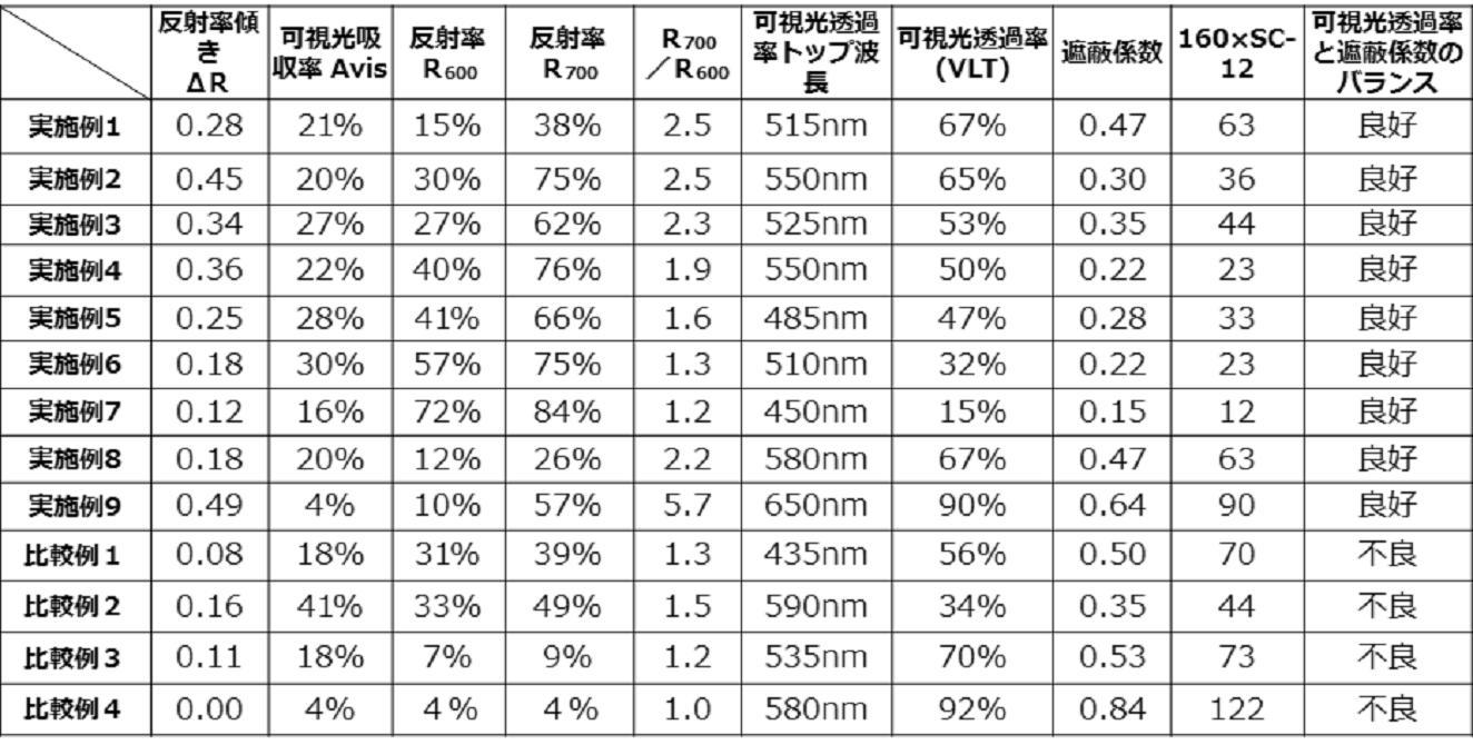
表1から理解されるように、実施例1から9はいずれも、波長600nmと波長700nmの間の反射率の傾きが、0.12以上であり、かつ、可視光吸収率が、30%未満である。そのため、実施例1から9のいずれも、高い可視光透過率を備えると共に、低い遮蔽係数を備え、可視光透過率と遮蔽係数のバランスが、いずれも良好となっている。この結果は、反射率の傾きが高く、近赤外線における、反射率が高いので、遮蔽係数が低くなる一方で、可視光領域において、反射率が低いと共に、可視光吸収率が低いため、可視光透過率が高くなることによる。また、いずれの実施例においても、可視光透過率のトップ波長が、450nmから650nmまでの範囲内にあるため、可視光領域の中でも両端、すなわち400nmと700nmと離れた位置に可視光トップ波長が存在し、高い可視光透過率を有している。
As understood from Table 1, in all of Examples 1 to 9, the slope of the reflectance between the wavelength 600 nm and the wavelength 700 nm is 0.12 or more, and the visible light absorption rate is less than 30%. It is. Therefore, all of Examples 1 to 9 have a high visible light transmittance and a low shielding coefficient, and the balance between the visible light transmittance and the shielding coefficient is good. As a result, the slope of reflectance is high and the reflectance in near infrared rays is high, so the shielding coefficient is low, while the reflectance in the visible light region is low and the absorptivity of visible light is low. It is because the transmittance becomes high. Further, in any of the embodiments, since the top wavelength of the visible light transmittance is in the range of 450 nm to 650 nm, the visible light top wavelength is at a position distant from both ends in the visible light region, that is, 400 nm and 700 nm. It is present and has high visible light transmission.
一方で、比較例1、比較例3及び比較例4は、反射率の傾きが0.12よりも小さく、可視光透過率と遮蔽係数のバランスが悪化している。特に、比較例1では、435nmが、可視光透過率のトップ波長であり、可視光領域全体では透過率低い。また、比較例4では、反射率の傾きが0.00であることから、可視光透過率と遮蔽係数のバランスが、不良となっており、160×SC-12の値が122となり、可視光透過率92%を大幅に超えている。
On the other hand, in Comparative Example 1, Comparative Example 3 and Comparative Example 4, the slope of the reflectance is smaller than 0.12, and the balance between the visible light transmittance and the shielding coefficient is deteriorated. In particular, in Comparative Example 1, 435 nm is the top wavelength of the visible light transmittance, and the transmittance is low in the entire visible light region. Further, in Comparative Example 4, since the slope of the reflectance is 0.00, the balance between the visible light transmittance and the shielding coefficient is poor, and the value of 160 × SC-12 is 122, which is visible light. The transmittance is significantly over 92%.
また、比較例2は、反射率の傾きは、0.16と高い値を持つが、可視光吸収率が41%と高いため、可視光透過率が低く、可視光透過率と遮蔽係数のバランスが悪くなっている。
Further, in Comparative Example 2, although the slope of reflectance has a high value of 0.16, the visible light absorptivity is as high as 41%, so the visible light transmittance is low, and the balance between the visible light transmittance and the shielding coefficient Is getting worse.
図9aに実施例1の350nmから800nmの透過、吸収、反射スペクトルを、図9bに比較例1の同様のスペクトルを示す。実施例1では、波長600nmにおいて、反射率が10%であり、低い一方で、波長700nmにおいて、30%近くにまで高まっており、波長600nmと波長700nmにおいて、反射率の傾きが大きくなっている。一方で、比較例1では、反射率が波長400nmから長波長側にかけてなだらかに高まっている。そのため、遮蔽係数は、可視光透過率が低く、56%にとどまる。
The transmission, absorption and reflection spectra of 350 nm to 800 nm of Example 1 are shown in FIG. 9a, and the similar spectrum of Comparative Example 1 is shown in FIG. 9b. In Example 1, the reflectance is 10% at a wavelength of 600 nm, and while it is low, it increases to nearly 30% at a wavelength of 700 nm, and the slope of the reflectance is large at a wavelength of 600 nm and a wavelength of 700 nm. . On the other hand, in Comparative Example 1, the reflectance is gradually increased from the wavelength of 400 nm to the long wavelength side. Therefore, the shielding coefficient is low at visible light transmittance and remains at 56%.
また、図10aに実施例9の400nmから900nmの透過、吸収、反射スペクトルを、図10bに比較例4の同様のスペクトルを示す。実施例9では、波長600nmにおいて、反射率が10%以下であり、低い一方で、波長700nmにおいて、40%を超えており、波長600nmと波長700nmとの間において、反射率の傾きが大きくなっている。一方で、比較例4では、波長600nm及び700nmのいずれにおいても反射率が、10%を下回っている。そして、750nm付近よりも長波長側において、反射率の傾きが大きくなり、波長850nm近辺で40%を超える。そのため、比較例4の遮蔽係数が、極めて高くなり、0.84となっている。一方で、比較例4の可視光透過率は、実施例9よりも高いが、実施例9の90%に対し比較例4の92%とわずか2%しか向上していない。これは、700nm付近においては、重課係数が低いため、700nm付近における透過率を増加させても、可視光透過率全体における増加率は、限定的であるからである。
10a shows the transmission, absorption and reflection spectra of 400 nm to 900 nm of Example 9, and FIG. 10b shows a similar spectrum of Comparative Example 4. In Example 9, the reflectance is 10% or less at a wavelength of 600 nm, and is low while it exceeds 40% at a wavelength of 700 nm, and the slope of the reflectance becomes large between the wavelength of 600 nm and the wavelength of 700 nm. ing. On the other hand, in Comparative Example 4, the reflectance is less than 10% at any of the wavelengths of 600 nm and 700 nm. Then, on a longer wavelength side than near 750 nm, the slope of the reflectance becomes larger, and exceeds 40% at a wavelength of around 850 nm. Therefore, the shielding coefficient of Comparative Example 4 is extremely high and is 0.84. On the other hand, although the visible light transmittance of Comparative Example 4 is higher than that of Example 9, it is improved by only 2% and 92% of Comparative Example 4 to 90% of Example 9. This is because, at around 700 nm, the weighting factor is low, so even if the transmittance at around 700 nm is increased, the rate of increase in the overall visible light transmittance is limited.
図11に、実施例及び比較例の遮蔽係数と可視光透過率の関係を表すグラフを示す。横軸が遮蔽係数であり、縦軸が、可視光透過率である。なお、実施例1と8は、遮蔽係数及び可視光透過率が同一の値であったため、一つの点として示されている。
FIG. 11 is a graph showing the relationship between the shielding coefficient and the visible light transmittance in the example and the comparative example. The horizontal axis is the shielding coefficient, and the vertical axis is the visible light transmittance. Examples 1 and 8 are shown as one point because the shielding coefficient and the visible light transmittance are the same value.
図11によると、実施例では、いずれもVLT≧160×SC-12の条件を充足する。一方で、比較例では、かかる条件を充足しない。また、当業者であれば、実施例に基づき、遮蔽係数を高めて、可視光透過率を上げる、また、その逆を行うことができる。例えば、実施例2では、VLT-160×SCの値が、17になるため、実施例2の構成を基に、VLT=160×SC+17を充足する高性能の偏光フィルムを製造することができる。
According to FIG. 11, in any of the embodiments, the condition VLT ≧ 160 × SC-12 is satisfied. On the other hand, in the comparative example, such a condition is not satisfied. In addition, one skilled in the art can increase the shielding coefficient to increase the visible light transmittance, and vice versa, based on the embodiment. For example, in Example 2, since the value of VLT-160 × SC is 17, based on the configuration of Example 2, a high-performance polarizing film satisfying VLT = 160 × SC + 17 can be manufactured.
以上、本発明を特定の実施形態について図示し、説明したが、本発明は、図示の実施形態に限定されるものではなく、本発明の範囲は、特許請求の範囲の請求項によってのみ定まるものである。
While the present invention has been illustrated and described with respect to particular embodiments, the present invention is not limited to the illustrated embodiments, the scope of the present invention being defined solely by the appended claims It is.
100 赤外線反射基板
10 透明基材
20 赤外線反射層
50 窓ガラス
60 粘着剤層
500 赤外線反射層500
510 第1の積層体
512 第1の金属酸化物層
514 第1の金属層
516 第2の金属酸化物層
530 透明スペーサ層
550 第2の積層体
552 第3の金属酸化物層
554 第2の金属層
556 第4の金属酸化物層
600 赤外線反射基板
612 第1の金属酸化物層
614 第1の金属層
616 第2の金属酸化物層
618 第2の金属層
620 第3の金属酸化物層
622 第3の金属層
624 第4の金属酸化物層 DESCRIPTION OFSYMBOLS 100 infrared reflective substrate 10 transparent base material 20 infrared reflective layer 50 window glass 60 adhesive layer 500 infrared reflective layer 500
510 firststacked body 512 first metal oxide layer 514 first metal layer 516 second metal oxide layer 530 transparent spacer layer 550 second stacked body 552 third metal oxide layer 554 second Metal layer 556 fourth metal oxide layer 600 infrared reflective substrate 612 first metal oxide layer 614 first metal layer 616 second metal oxide layer 618 second metal layer 620 third metal oxide layer 622 third metal layer 624 fourth metal oxide layer
10 透明基材
20 赤外線反射層
50 窓ガラス
60 粘着剤層
500 赤外線反射層500
510 第1の積層体
512 第1の金属酸化物層
514 第1の金属層
516 第2の金属酸化物層
530 透明スペーサ層
550 第2の積層体
552 第3の金属酸化物層
554 第2の金属層
556 第4の金属酸化物層
600 赤外線反射基板
612 第1の金属酸化物層
614 第1の金属層
616 第2の金属酸化物層
618 第2の金属層
620 第3の金属酸化物層
622 第3の金属層
624 第4の金属酸化物層 DESCRIPTION OF
510 first
Claims (8)
- 透明基材と、前記基材上に赤外線反射層とを備える赤外線反射基板であって、
前記赤外線反射基板の可視光吸収率は、0.3以下であり、
前記赤外線反射基板の700nmと600nmの反射率の傾きdR700-600が0.12以上であり、
前記反射率の傾きdR700-600(%/nm)は、600nmの波長における前記透明基材側からの反射率をR600(%)とし、前記赤外線反射フィルムの700nmの波長における前記透明基材側からの反射率をR700(%)とすると、
dR700-600=(R700-R600)/100(nm)
で表される、
ことを特徴とする赤外線反射基板。 An infrared reflective substrate comprising: a transparent substrate; and an infrared reflective layer on the substrate,
The visible light absorptivity of the infrared reflective substrate is 0.3 or less,
The reflectance dR 700-600 of the reflectance of 700 nm and 600 nm of the infrared reflective substrate is 0.12 or more,
In the reflectance dR 700-600 (% / nm) of the reflectance, the reflectance from the transparent substrate side at a wavelength of 600 nm is R 600 (%), and the transparent substrate at a wavelength of 700 nm of the infrared reflective film Assuming that the reflectance from the side is R 700 (%),
dR 700-600 = (R 700 -R 600 ) / 100 (nm)
Represented by
An infrared reflective substrate characterized by - 前記反射率R600は、10%以上かつ60%以下である、ことを特徴とする請求項1に記載の赤外線反射基板。 The infrared reflective substrate according to claim 1, wherein the reflectance R 600 is 10% or more and 60% or less.
- 前記反射率R700は、25%以上かつ85%以下である、ことを特徴とする請求項1又は2に記載の赤外線反射基板。 The infrared reflective substrate according to claim 1, wherein the reflectance R 700 is 25% or more and 85% or less.
- 前記反射率R600に対する前記反射率R700の比率R700/R600は、1.2以上である、ことを特徴とする請求項1から3のいずれか1項に記載の赤外線反射基板。 The infrared reflective substrate according to any one of claims 1 to 3, wherein a ratio R700 / R600 of the reflectance R700 to the reflectance R600 is 1.2 or more.
- 可視光透過率トップ波長が、450nmから650nmまでの間にある、ことを特徴とする請求項1から4のいずれか1項に記載の赤外線反射基板。 The infrared reflective substrate according to any one of claims 1 to 4, wherein the visible light transmittance top wavelength is between 450 nm and 650 nm.
- 前記透明基材が、フィルムであり、
前記透明基材の赤外線反射層を備える面とは、逆側の面に、粘着剤層を備えることを特徴とする請求項1から5のいずれか1項に記載の赤外線反射基板。 The transparent substrate is a film,
The infrared reflective substrate according to any one of claims 1 to 5, wherein a pressure-sensitive adhesive layer is provided on the surface opposite to the surface provided with the infrared reflective layer of the transparent substrate. - 前記透明基材が、ガラスであることを特徴とする請求項1から5のいずれか1項に記載の赤外線反射基板。 The infrared reflective substrate according to any one of claims 1 to 5, wherein the transparent substrate is glass.
- 前記赤外線反射基板はさらに、赤外線反射層上に、透明保護フィルムを備えることを特徴とする請求項1から7のいずれか1項に記載の赤外線反射基板。 The infrared reflective substrate according to any one of claims 1 to 7, further comprising a transparent protective film on the infrared reflective layer.
Priority Applications (4)
| Application Number | Priority Date | Filing Date | Title |
|---|---|---|---|
| CN201880043054.2A CN110809724A (en) | 2017-06-26 | 2018-05-24 | Infrared reflection substrate |
| EP18825418.9A EP3647838A4 (en) | 2017-06-26 | 2018-05-24 | Infrared ray-reflective substrate |
| KR1020207002238A KR20200016388A (en) | 2017-06-26 | 2018-05-24 | Infrared reflective substrate |
| US16/626,648 US20200241184A1 (en) | 2017-06-26 | 2018-05-24 | Infrared ray-reflective substrate |
Applications Claiming Priority (2)
| Application Number | Priority Date | Filing Date | Title |
|---|---|---|---|
| JP2017124122A JP2019008157A (en) | 2017-06-26 | 2017-06-26 | Infrared reflection substrate |
| JP2017-124122 | 2017-06-26 |
Publications (1)
| Publication Number | Publication Date |
|---|---|
| WO2019003733A1 true WO2019003733A1 (en) | 2019-01-03 |
Family
ID=64742948
Family Applications (1)
| Application Number | Title | Priority Date | Filing Date |
|---|---|---|---|
| PCT/JP2018/019946 WO2019003733A1 (en) | 2017-06-26 | 2018-05-24 | Infrared ray-reflective substrate |
Country Status (6)
| Country | Link |
|---|---|
| US (1) | US20200241184A1 (en) |
| EP (1) | EP3647838A4 (en) |
| JP (1) | JP2019008157A (en) |
| KR (1) | KR20200016388A (en) |
| CN (1) | CN110809724A (en) |
| WO (1) | WO2019003733A1 (en) |
Families Citing this family (1)
| Publication number | Priority date | Publication date | Assignee | Title |
|---|---|---|---|---|
| CN114574120A (en) * | 2022-04-02 | 2022-06-03 | 极天羽技术股份有限公司 | Recyclable infrared blocking protective film and preparation method thereof |
Citations (10)
| Publication number | Priority date | Publication date | Assignee | Title |
|---|---|---|---|---|
| JPH04504555A (en) * | 1986-06-30 | 1992-08-13 | サウスウォール テクノロジーズ,インコーポレイテッド | Multilayer heat reflective composite film and window glass products containing the film |
| JP2000098131A (en) * | 1998-09-28 | 2000-04-07 | Nitto Denko Corp | Filter for plasma display panel |
| JP2000117871A (en) * | 1998-10-09 | 2000-04-25 | Suzutora:Kk | Selective light transmitting film |
| JP2006505811A (en) * | 2002-11-05 | 2006-02-16 | ナムローゼ・フェンノートシャップ・ベーカート・ソシエテ・アノニム | Infrared reflective laminated structure |
| JP2010149347A (en) * | 2008-12-25 | 2010-07-08 | Tokai Rubber Ind Ltd | Transparent laminated film |
| JP2011509193A (en) | 2007-12-28 | 2011-03-24 | スリーエム イノベイティブ プロパティズ カンパニー | Infrared reflective film for solar control and other uses |
| WO2011040578A1 (en) * | 2009-09-30 | 2011-04-07 | 旭硝子株式会社 | Near-infrared-absorbing particles, process for producing same, dispersion, and article thereof |
| JP2012009873A (en) * | 2004-11-30 | 2012-01-12 | Asahi Glass Co Ltd | Conductive stacked body, manufacturing method for the same, electromagnetic wave shielding film for plasma display, and protection plate for plasma display |
| JP2013061370A (en) | 2011-09-12 | 2013-04-04 | Nitto Denko Corp | Infrared reflection film |
| WO2017131174A1 (en) * | 2016-01-29 | 2017-08-03 | 日立マクセル株式会社 | Transparent heat-shielding/heat-insulating member having transparent screen function |
-
2017
- 2017-06-26 JP JP2017124122A patent/JP2019008157A/en active Pending
-
2018
- 2018-05-24 WO PCT/JP2018/019946 patent/WO2019003733A1/en unknown
- 2018-05-24 US US16/626,648 patent/US20200241184A1/en not_active Abandoned
- 2018-05-24 KR KR1020207002238A patent/KR20200016388A/en unknown
- 2018-05-24 CN CN201880043054.2A patent/CN110809724A/en active Pending
- 2018-05-24 EP EP18825418.9A patent/EP3647838A4/en not_active Withdrawn
Patent Citations (10)
| Publication number | Priority date | Publication date | Assignee | Title |
|---|---|---|---|---|
| JPH04504555A (en) * | 1986-06-30 | 1992-08-13 | サウスウォール テクノロジーズ,インコーポレイテッド | Multilayer heat reflective composite film and window glass products containing the film |
| JP2000098131A (en) * | 1998-09-28 | 2000-04-07 | Nitto Denko Corp | Filter for plasma display panel |
| JP2000117871A (en) * | 1998-10-09 | 2000-04-25 | Suzutora:Kk | Selective light transmitting film |
| JP2006505811A (en) * | 2002-11-05 | 2006-02-16 | ナムローゼ・フェンノートシャップ・ベーカート・ソシエテ・アノニム | Infrared reflective laminated structure |
| JP2012009873A (en) * | 2004-11-30 | 2012-01-12 | Asahi Glass Co Ltd | Conductive stacked body, manufacturing method for the same, electromagnetic wave shielding film for plasma display, and protection plate for plasma display |
| JP2011509193A (en) | 2007-12-28 | 2011-03-24 | スリーエム イノベイティブ プロパティズ カンパニー | Infrared reflective film for solar control and other uses |
| JP2010149347A (en) * | 2008-12-25 | 2010-07-08 | Tokai Rubber Ind Ltd | Transparent laminated film |
| WO2011040578A1 (en) * | 2009-09-30 | 2011-04-07 | 旭硝子株式会社 | Near-infrared-absorbing particles, process for producing same, dispersion, and article thereof |
| JP2013061370A (en) | 2011-09-12 | 2013-04-04 | Nitto Denko Corp | Infrared reflection film |
| WO2017131174A1 (en) * | 2016-01-29 | 2017-08-03 | 日立マクセル株式会社 | Transparent heat-shielding/heat-insulating member having transparent screen function |
Non-Patent Citations (1)
| Title |
|---|
| See also references of EP3647838A4 |
Also Published As
| Publication number | Publication date |
|---|---|
| CN110809724A (en) | 2020-02-18 |
| EP3647838A4 (en) | 2021-03-24 |
| JP2019008157A (en) | 2019-01-17 |
| EP3647838A1 (en) | 2020-05-06 |
| US20200241184A1 (en) | 2020-07-30 |
| KR20200016388A (en) | 2020-02-14 |
Similar Documents
| Publication | Publication Date | Title |
|---|---|---|
| US10007037B2 (en) | Infrared-ray reflective film | |
| AU2014213392B2 (en) | Infrared radiation reflecting film | |
| JP6423198B2 (en) | Infrared reflective film | |
| US20170067593A1 (en) | Transparent heat-shielding/heat-insulating member and production method thereof | |
| JP5959746B2 (en) | Light transmissive laminate | |
| JP2008036864A (en) | Laminate, laminated glass using the laminate and glass sheet | |
| JP2017122779A (en) | Infrared reflection film | |
| JP6163196B2 (en) | Infrared reflective film | |
| JPWO2019004199A1 (en) | Transparent heat insulating and heat insulating member and method for manufacturing the same | |
| WO2019003733A1 (en) | Infrared ray-reflective substrate | |
| JP6370347B2 (en) | Infrared reflective film | |
| JP7057714B2 (en) | Transparent heat shield and heat insulating member and its manufacturing method | |
| JP2022006679A (en) | Transparent heat blocking and heat insulating member and method for manufacturing the same | |
| JP2008036866A (en) | Transfer foil and glass sheet, acrylic plate, or polycarbonate plate using transfer foil | |
| JP5895089B1 (en) | Heat ray shielding laminate and window glass using the laminate | |
| JP2007118227A (en) | Reflection reducing near infrared absorbing material and electronic image display device using it | |
| WO2016199661A1 (en) | Heat-ray-shielding layered body and window glass using heat-ray-shielding layered body |
Legal Events
| Date | Code | Title | Description |
|---|---|---|---|
| 121 | Ep: the epo has been informed by wipo that ep was designated in this application |
Ref document number: 18825418 Country of ref document: EP Kind code of ref document: A1 |
|
| NENP | Non-entry into the national phase |
Ref country code: DE |
|
| ENP | Entry into the national phase |
Ref document number: 20207002238 Country of ref document: KR Kind code of ref document: A |
|
| ENP | Entry into the national phase |
Ref document number: 2018825418 Country of ref document: EP Effective date: 20200127 |