WO2019003278A1 - Method for controlling direction indicator and device for controlling direction indicator - Google Patents
Method for controlling direction indicator and device for controlling direction indicator Download PDFInfo
- Publication number
- WO2019003278A1 WO2019003278A1 PCT/JP2017/023422 JP2017023422W WO2019003278A1 WO 2019003278 A1 WO2019003278 A1 WO 2019003278A1 JP 2017023422 W JP2017023422 W JP 2017023422W WO 2019003278 A1 WO2019003278 A1 WO 2019003278A1
- Authority
- WO
- WIPO (PCT)
- Prior art keywords
- roundabout
- vehicle
- road
- exit
- path
- Prior art date
Links
Images


Classifications
-
- G—PHYSICS
- G01—MEASURING; TESTING
- G01C—MEASURING DISTANCES, LEVELS OR BEARINGS; SURVEYING; NAVIGATION; GYROSCOPIC INSTRUMENTS; PHOTOGRAMMETRY OR VIDEOGRAMMETRY
- G01C21/00—Navigation; Navigational instruments not provided for in groups G01C1/00 - G01C19/00
- G01C21/26—Navigation; Navigational instruments not provided for in groups G01C1/00 - G01C19/00 specially adapted for navigation in a road network
- G01C21/34—Route searching; Route guidance
- G01C21/36—Input/output arrangements for on-board computers
- G01C21/3626—Details of the output of route guidance instructions
- G01C21/3658—Lane guidance
-
- B—PERFORMING OPERATIONS; TRANSPORTING
- B60—VEHICLES IN GENERAL
- B60Q—ARRANGEMENT OF SIGNALLING OR LIGHTING DEVICES, THE MOUNTING OR SUPPORTING THEREOF OR CIRCUITS THEREFOR, FOR VEHICLES IN GENERAL
- B60Q1/00—Arrangement of optical signalling or lighting devices, the mounting or supporting thereof or circuits therefor
- B60Q1/26—Arrangement of optical signalling or lighting devices, the mounting or supporting thereof or circuits therefor the devices being primarily intended to indicate the vehicle, or parts thereof, or to give signals, to other traffic
- B60Q1/34—Arrangement of optical signalling or lighting devices, the mounting or supporting thereof or circuits therefor the devices being primarily intended to indicate the vehicle, or parts thereof, or to give signals, to other traffic for indicating change of drive direction
- B60Q1/346—Arrangement of optical signalling or lighting devices, the mounting or supporting thereof or circuits therefor the devices being primarily intended to indicate the vehicle, or parts thereof, or to give signals, to other traffic for indicating change of drive direction with automatic actuation
-
- G—PHYSICS
- G01—MEASURING; TESTING
- G01C—MEASURING DISTANCES, LEVELS OR BEARINGS; SURVEYING; NAVIGATION; GYROSCOPIC INSTRUMENTS; PHOTOGRAMMETRY OR VIDEOGRAMMETRY
- G01C21/00—Navigation; Navigational instruments not provided for in groups G01C1/00 - G01C19/00
- G01C21/26—Navigation; Navigational instruments not provided for in groups G01C1/00 - G01C19/00 specially adapted for navigation in a road network
- G01C21/34—Route searching; Route guidance
- G01C21/36—Input/output arrangements for on-board computers
- G01C21/3626—Details of the output of route guidance instructions
- G01C21/3632—Guidance using simplified or iconic instructions, e.g. using arrows
-
- G—PHYSICS
- G01—MEASURING; TESTING
- G01C—MEASURING DISTANCES, LEVELS OR BEARINGS; SURVEYING; NAVIGATION; GYROSCOPIC INSTRUMENTS; PHOTOGRAMMETRY OR VIDEOGRAMMETRY
- G01C21/00—Navigation; Navigational instruments not provided for in groups G01C1/00 - G01C19/00
- G01C21/26—Navigation; Navigational instruments not provided for in groups G01C1/00 - G01C19/00 specially adapted for navigation in a road network
- G01C21/34—Route searching; Route guidance
- G01C21/36—Input/output arrangements for on-board computers
- G01C21/3667—Display of a road map
-
- G—PHYSICS
- G08—SIGNALLING
- G08G—TRAFFIC CONTROL SYSTEMS
- G08G1/00—Traffic control systems for road vehicles
- G08G1/09—Arrangements for giving variable traffic instructions
- G08G1/0962—Arrangements for giving variable traffic instructions having an indicator mounted inside the vehicle, e.g. giving voice messages
- G08G1/0968—Systems involving transmission of navigation instructions to the vehicle
- G08G1/0969—Systems involving transmission of navigation instructions to the vehicle having a display in the form of a map
-
- B—PERFORMING OPERATIONS; TRANSPORTING
- B60—VEHICLES IN GENERAL
- B60R—VEHICLES, VEHICLE FITTINGS, OR VEHICLE PARTS, NOT OTHERWISE PROVIDED FOR
- B60R11/00—Arrangements for holding or mounting articles, not otherwise provided for
- B60R11/04—Mounting of cameras operative during drive; Arrangement of controls thereof relative to the vehicle
Definitions
- the present invention relates to a direction indicator control method and a direction indicator controller.
- the rule of the direction indication at the roundabout may be different from the rule at a crossroad or the like. Therefore, with the above-described technology, it is not always possible to perform the turn indication in accordance with the rules in the roundabout.
- the present invention has been made in view of the above problems, and it is an object of the present invention to provide a direction indicator control method and a direction indicator controller capable of performing direction indication according to a rule in a roundabout.
- the direction indicator control method determines the position of the approach road to the roundabout and the position of the exit road when there is a roundabout on the planned traveling road of the vehicle, and indicates the direction when entering Is determined based on the relationship between the position of the approach route and the position of the exit route.
- the turn indication can be performed according to the rules in the roundabout.
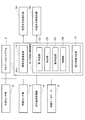
- FIG. 1 is a functional block diagram showing a part of a vehicle equipped with a turn signal controller according to an embodiment of the present invention.
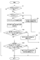
- FIG. 2 is a flowchart for explaining the direction indicator control method performed by the direction indicator controller 12.
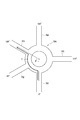
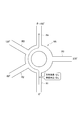
- FIG. 3 is a diagram for explaining the azimuth angle of the road connecting to the roundabout.
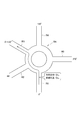
- FIG. 4 is a diagram showing a specific example of direction indication and lane determination when the exit road is adjacent to the entrance road.
- FIG. 5 is a diagram showing a specific example of the direction indication and the lane determination when the angle formed by the exit path with respect to the entrance path is greater than 180 degrees.
- FIG. 1 is a functional block diagram showing a part of a vehicle equipped with a turn signal controller according to an embodiment of the present invention.
- FIG. 2 is a flowchart for explaining the direction indicator control method performed by the direction indicator controller 12.
- FIG. 3 is a diagram for explaining the azimuth angle of the road connecting to the roundabout.
- FIG. 4 is a diagram showing
- FIG. 6 is a diagram showing a first specific example of direction indication and lane determination when the exit path makes an angle of 180 degrees or less with respect to the entrance path and the exit path is not adjacent to the entrance path.
- FIG. 7 is a diagram showing a second specific example of the direction indication and the lane determination when the exit path makes an angle of 180 degrees or less with respect to the entrance path and the exit path is not adjacent to the entrance path.
- the vehicle includes an electronic control unit (ECU) 1, an external sensor unit 2, an internal sensor unit 3, a GPS (Global Positioning System) radio wave receiving unit 4, a map database 5, a navigation system 6, a vehicle exterior direction An indicator 7A and a vehicle interior direction indicator 7B are provided.
- ECU electronice control unit
- an external sensor unit 2 an external sensor unit 2
- an internal sensor unit 3 a GPS (Global Positioning System) radio wave receiving unit 4
- a map database 5 a navigation system 6
- vehicle exterior direction indicator 7A and a vehicle interior direction indicator 7B are provided.
- the vehicle shown in FIG. 1 is referred to as "the vehicle” so as not to be confused with other vehicles.
- the vehicle exterior direction indicator 7A and the vehicle interior direction indicator 7B are collectively referred to as a direction indicator.
- the ECU 1 includes a control unit (control circuit) of the direction indicator control device (control device), and can be realized using a microcomputer including a CPU (central processing unit), a memory, and an input / output unit.
- a computer program for causing the microcomputer to function as the ECU 1 is installed in the microcomputer and executed.
- the microcomputer functions as the ECU 1.
- the example which realizes ECU1 by software is shown, of course, it is also possible to prepare ECU1 for exclusive use for performing each information processing shown below, and to constitute ECU1.
- the external sensor unit 2 includes a radar device or a camera (both not shown), and outputs ambient information of the host vehicle obtained from the radar device or the camera to the ECU 1 and the navigation system 6.
- the internal sensor unit 3 includes a vehicle speed sensor or a yaw angle sensor (both not shown), and outputs the vehicle speed or the yaw angle obtained from the vehicle speed sensor or the yaw angle sensor to the ECU 1 and the navigation system 6.
- the GPS radio wave receiver 4 receives radio waves from three or more GPS satellites to obtain position information indicating the position of the host vehicle, and outputs the position information to the ECU 1 and the navigation system 6.
- the map database 5 includes map information of a region where the host vehicle travels, and the ECU 1 and the navigation system 6 refer to the map information.
- Map information includes information such as the locations of roads and intersections.
- the intersections include round intersections called roundabouts in addition to cross intersections and T-shaped intersections.
- a roundabout is an intersection where three or more roads connect to a ring road (referred to as a ring road), and in this case, the round about is a ring road.
- the map information includes roundabout information.
- the roundabout information includes information indicating the traveling direction (clockwise or counterclockwise direction) of the host vehicle in the roundabout and the position of each connected road.
- the information indicating the position of each road includes the azimuth angle of the road when the traveling direction of the vehicle at the roundabout is positive with reference to a predetermined direction (for example, north direction) from the center position of the ring road.
- the navigation system 6 provides guidance to a destination set by an occupant such as a driver of the host vehicle.
- the navigation system 6 estimates the position of the vehicle based on the information output from the external sensor unit 2, the internal sensor unit 3, and the GPS radio wave receiving unit 4, calculates a planned traveling route to the destination, and reaches the destination To give guidance.
- the navigation system 6 outputs information on the planned traveling route to the ECU 1.
- the ECU 1 includes a vehicle position estimation unit 11, a turn indicator control unit 12, and a traveling lane determination unit 13.
- the vehicle position estimation unit 11 estimates the position of the host vehicle based on the information output from the external sensor unit 2, the internal sensor unit 3, and the GPS radio wave reception unit 4.
- the direction indicator control unit 12 corresponds to a control unit (control circuit) of the direction indicator control device (control device).
- the direction indicator control unit 12 is based on the position information of the vehicle obtained by the vehicle position estimation unit 11, the map information of the map database 5, and the information on the planned traveling route generated by the navigation system 6, 7A and the vehicle interior direction indicator 7B are controlled.
- the direction indicator control unit 12 includes a first determination unit (first determination circuit) 121, a calculation unit (calculation circuit) 122, a second determination unit (second determination circuit) 123, and a control unit (control circuit) 124. And.
- the first determination unit 121 determines whether or not there is a roundabout on the planned travel route on which the host vehicle is to travel.
- the calculation unit 122 obtains an entry path where the host vehicle enters the roundabout and an exit road where the host vehicle exits the roundabout.
- the second determination unit 123 determines, based on the relationship between the position of the entry route and the position of the exit route, whether or not the direction indicator (7A, 7B) requires a direction indication when the host vehicle enters the roundabout. judge.
- the control unit 124 controls the outdoor direction indicator 7A and the indoor direction indicator 7B.
- the outdoor direction indicator 7A includes a turn indicator light for right turn and a turn indicator light for left turn attached to the outer part of the host vehicle to notify other vehicles or pedestrians of right turn and left turn.
- the vehicle interior direction indicator 7B includes a turn indicator light for right turn and a turn indicator light for left turn mounted in the host vehicle to notify an occupant such as a driver of a right turn and a left turn.
- both the direction indicator lights of the right turn of the outdoor direction indicator 7A and the indoor direction indicator 7B light up, and at this time, the outdoor direction indicator 7A and the indoor direction indicator
- the left turn indicator lights on 7B turn off together.
- the turn indicator lights of the left turn are both turned on, and at this time, the turn indicator lights of the right turn are both turned off.
- the exterior direction indicator 7A and the interior direction indicator 7B operate in synchronization with each other.
- the travel lane determination unit 13 determines the position of the entrance road and the position of the road on which the host vehicle exits the roundabout (exit road). Based on the relationship, it is determined whether or not the host vehicle is in the appropriate lane.
- the direction indicator control method performed by the direction indicator controller 12 will be described.
- control of the feature of the embodiment will be described on the premise of control of a direction indicator that gives a direction indication in the direction in which the vehicle travels when the vehicle enters a point where roads are connected.
- the planned travel road is a route for making a right turn at an intersection or the like
- the right turn indicator is automatically operated in front of the intersection.
- the vehicle is traveling by the guidance of the navigation system 6 based on the information of the planned traveling route.
- the turn signal controller 12 determines whether the own vehicle approaches an intersection based on the position of the own vehicle estimated by the vehicle position estimation unit 11 and the map information of the map database 5. If it is not approaching (S1: NO), the process ends.
- the first determination unit 121 of the turn indicator control unit 12 determines whether the intersection is a roundabout (S3). That is, the first determination unit 121 determines whether or not there is a roundabout on the planned travel route on which the host vehicle is to travel.
- step S5 specifically, based on the information on the planned traveling road, the direction indication in the right direction is started when turning right at the intersection, and the direction indication in the left direction is started when turning left (S5).
- the direction indicator 7A outside the vehicle and the direction indicator 7B inside the vehicle room turn on the right turn indicator light when turning right at the intersection, and turn on the left turn indicator light when turning left.
- the direction indicator control unit 12 acquires the information about the roundabout from the map information (S21) .
- the calculation unit 122 of the turn indicator control unit 12 determines the position of the road (hereinafter referred to as the entrance road) where the own vehicle enters the roundabout
- the position of the road on which the vehicle exits from the roundabout (hereinafter referred to as exit route) is determined (S23).
- the occupant of the host vehicle may designate the position of the approach path and the position of the exit path.
- the turn signal controller control portion 12 second determination portion 123 determines whether or not the turn signal is necessary in the exterior direction indicator 7A and the interior direction indicator 7B when the host vehicle enters the roundabout. The determination is made based on the relationship between the position of the road and the position of the exit road.
- the second determination unit 123 of the turn indicator control unit 12 first determines whether the exit path is adjacent to the approach path on the traveling direction side in the roundabout (S25).
- the turn signal controller 12 sets the azimuth angle (positive angle) of another road (including the exit road) when the azimuth angle of the approach road is 0 ° (degree). Angle) is calculated, and a determination is made based on the azimuth angle (S25).
- Roads R1 to R5 are connected to the roundabout RA.
- the traveling direction in the roundabout RA is clockwise.
- the road R1 is an approach road.
- the azimuth angles of the roads R2 to R5 are 60 ° (degree), 120 ° (degree), 180 ° (degree) in order. It is 270 degrees (degree).
- the road R3 is an exit road, the host vehicle travels along the arrow T.
- the azimuth of the exit path is ⁇ in FIG. 4, that is, 120 ° (degrees).
- the control unit 124 of the turn indicator control unit 12 determines that the exit path is adjacent to the approach path on the traveling direction side (S25: YES), the exterior direction indicator 7A and the interior direction command When the vehicle leaves the roundabout, the control unit 7B starts the direction indication of the turning direction (S27), and ends the processing.
- the direction in which the vehicle turns when exiting from the roundabout is hereinafter referred to as the "direction of bend.”
- the bending direction is, in other words, the direction in which the vehicle bends when entering the exit road from the roundabout.
- the turn signal control unit 12 executes step S27 before entering the roundabout, that is, on the approach path.
- step S27 the direction indicator 7A outside the vehicle and the direction indicator 7B inside the vehicle room turn on the left turn indicator light when the traveling direction is clockwise, and in the counterclockwise direction, the right turn indicator light Light.
- the host vehicle enters the roundabout with the turn indicator light on.
- the exit path is for the entrance path. It is determined whether or not the angle to be formed is greater than 180 degrees with the direction of travel in the roundabout being positive (S29).
- the turn indicator control unit 12 second determination unit 123 determines that the azimuth of the exit road calculated in step S 25 (the azimuth of the exit road when the azimuth of the approach road is 0 degrees) is 180 degrees. It is determined whether or not it is larger (S29).
- the control unit 124 of the direction indicator control unit 12 responds to the exterior direction indicator 7A and the interior direction indicator 7B.
- the direction indication in the direction opposite to the bending direction is started (S31), and the process is ended.
- the turn signal control unit 12 executes step S29 before entering the roundabout, that is, on the approach path.
- the opposite direction of the bending direction is the right direction
- the traveling direction is counterclockwise
- the opposite direction of the bending direction is the left direction.
- the direction indicator 7A outside the vehicle and the direction indicator 7B inside the vehicle room turn on the right turn indicator light when the traveling direction is clockwise, and in the counterclockwise direction the left turn indicator light Light.
- the host vehicle enters the roundabout with the turn indicator light on.
- the control section 124 of the direction indicator control section 12 detects the exterior direction indicator 7A and the interior direction indicator 7B. End the process without starting direction indication.
- the host vehicle enters a roundabout with the turn indicator light turned off. That is, the direction indicator control unit 12 does not cause the direction indicator in the direction indicator to enter when entering the roundabout. That is, the turn indicator control unit 12 prohibits the turn indication of the turn indicator.
- the direction indicator control unit 12 performs the process of FIG. 2 for each intersection on the planned travel road. Although the end of the direction indication has not been described in the flowchart of FIG. 2, the direction indicator control unit 12 indicates the timing at which a predetermined time has elapsed since the start of the direction indication, or the timing at which the roundabout has passed. The direction indication can be ended at an appropriate timing based on the traffic rules.
- the traveling lane determination unit 13 determines whether or not the own vehicle is positioned in the lane on the side of the turn when the approach road includes a plurality of lanes and it is determined as YES in step S25 of FIG. The traveling lane determination unit 13 determines whether the approach road includes a plurality of lanes based on the map information.
- the traveling lane determination unit 13 determines whether or not the host vehicle is located in the left lane (for example, the leftmost lane).
- the traveling lane determination unit 13 determines whether the host vehicle is located in the right lane (for example, the rightmost lane).
- the traveling lane determination unit 13 urges lane change to the lane on the side of the turn, for example, by voice or screen display in the navigation system 6. This allows the host vehicle to enter the roundabout from the lane on the side of the turn, that is, the appropriate lane.
- the turn signal controller 12 causes the turn indicator (7A, 7B) to turn from the lane in which the host vehicle is located. If the lane on the direction side is the right side, the direction indication may be made to the right side, and if it is the left side, the direction indication may be made to the left side.
- the traveling lane determination unit 13 determines whether or not the own vehicle is positioned in the lane opposite to the turning direction. Do.
- the traveling lane determination unit 13 determines whether the host vehicle is located in the right lane (for example, the rightmost lane).
- the traveling lane determination unit 13 determines whether the host vehicle is positioned in the left lane (for example, the leftmost lane). judge.
- the traveling lane determination unit 13 determines that the host vehicle is not located in the lane opposite to the bending direction, for example, by voice or screen display in the navigation system 6, the lane opposite to the bending direction is displayed. Prompt to change lanes of This enables the host vehicle to enter the roundabout from the lane opposite to the direction of the turn, that is, the appropriate lane.
- the direction indicator controller 12 causes the direction indicator (7A, 7B) to be viewed from the lane in which the host vehicle is located. The direction may be directed to the right if the lane opposite to the turn direction is to the right, and to the left if the lane is to the left.
- the angle ⁇ formed by the road R5 (exit road) with respect to the road R1 (access road) may be larger than 270 degrees, that is, 180 degrees assuming that the traveling direction in the roundabout RA is positive. .
- the direction indication in the direction opposite to the turning direction (right in the case of the drawing) is started. Therefore, when the angle ⁇ is larger than 180 degrees, it is possible to perform the direction indication according to the rule in the roundabout of the rule of starting the direction indication in the opposite direction to the bending direction in the approach path. That is, it is possible to prevent entry into a roundabout without giving a direction indication or while giving a direction indication of a bending direction.
- the angle ⁇ made by the exit road (road R3 in FIG. 6, road R4 in FIG. 7) with respect to road R1 (access road) is positive in the direction of travel in roundabout RA. As it is less than 180 degrees.
- the exit road (R3, R4) is not adjacent to the advancing direction side in the roundabout RA with respect to the entrance road (R1). In this case, no direction is given when entering the roundabout RA. Therefore, when the angle ⁇ is equal to or less than 180 degrees and the exit path is not adjacent to the traveling direction on the traveling direction side, the rule of the direction indication can be observed in the roundabout of the rule not giving the direction indication. That is, it is possible to prevent entry into the roundabout with the direction indication.
- 4 to 7 are diagrams showing a specific example in a roundabout in which the vehicle travels clockwise.
- the angles ⁇ of the road R5 to the road R2 become 90 degrees, 180 degrees, 240 degrees, and 300 degrees in order. Therefore, the determination in step 29 of FIG. 2 is performed based on this angle ⁇ .
- the position of the entrance road and the position of the exit road are obtained, and the necessity of direction indication at the entry to the roundabout is indicated.
- the determination is made based on the relationship between the position of the road and the position of the exit road. Therefore, it is possible to perform the direction indication according to the rule in the roundabout of the rule that determines the necessity of the direction indication at the time of entry based on the relationship between the position of the entry path and the position of the exit path.
- the turn signal controller control device is mounted on a target vehicle for which a turn signal is to be issued.
- the direction indicator control device is mounted on a server device that can communicate with the target vehicle or on another vehicle that is not the target vehicle, and necessary information and instructions are transmitted and received by communication between the server device or the other vehicle and the target vehicle, A similar turn signal control method may be performed remotely. Communication between the server device and the target vehicle can be performed by wireless communication or road-vehicle communication. Communication between the other vehicle and the target vehicle can be performed by so-called inter-vehicle communication.
- the direction indicator blinks by turning on (energizes) the control circuit, and is turned off by turning it off. For example, the control circuit is turned off or turned off as control that does not perform the direction indicator. May be controlled to maintain.
Landscapes
- Engineering & Computer Science (AREA)
- Radar, Positioning & Navigation (AREA)
- Remote Sensing (AREA)
- Automation & Control Theory (AREA)
- Physics & Mathematics (AREA)
- General Physics & Mathematics (AREA)
- Mechanical Engineering (AREA)
- Navigation (AREA)
- Traffic Control Systems (AREA)
- Lighting Device Outwards From Vehicle And Optical Signal (AREA)
Abstract
Description
内部センサ部3は、車速センサ又はヨー角センサ(共に図示せず)を備え、車速センサ又はヨー角センサから得た車速又はヨー角をECU1及びナビゲーションシステム6に出力する。 The
The
車両位置推定部11は、外部センサ部2、内部センサ部3、GPS電波受信部4が出力した各情報を基に自車両の位置を推定する。方向指示器制御部12は、方向指示器制御装置(制御装置)の制御部(制御回路)に相当するものである。 The ECU 1 includes a vehicle
The vehicle
車室内方向指示器7Bは、運転者などの乗員に右折と左折を知らせるために自車両内に取り付けられた右折の方向指示灯及び左折の方向指示灯を備える。 The
The vehicle
なお、図2のフローチャートには方向指示の終了を記載しなかったが、方向指示器制御部12は、方向指示を開始してから所定の時間が経過したタイミング、又はラウンドアバウトを通過したタイミングなど、交通規則に基づく適切なタイミングで方向指示を終了させることができる。 The direction indicator control unit 12 performs the process of FIG. 2 for each intersection on the planned travel road.
Although the end of the direction indication has not been described in the flowchart of FIG. 2, the direction indicator control unit 12 indicates the timing at which a predetermined time has elapsed since the start of the direction indication, or the timing at which the roundabout has passed. The direction indication can be ended at an appropriate timing based on the traffic rules.
図4に示すように、道路R2(退出路)が、道路R1(進入路)に対してラウンドアバウトRAにおける進行方向側に隣接する場合、道路R1(進入路)において、曲がり方向(図の場合は左)の方向指示を開始させる。よって、退出路が進入路に対して進行方向側に隣接する場合は進入路において曲がり方向の方向指示を開始するというルールのラウンドアバウトにおいてルールに従った方向指示を行うことができる。すなわち、方向指示を行わないで、又は、曲がり方向とは反対方向の方向指示を行ったままラウンドアバウトに進入することを防止できる。 Next, specific examples of direction indication and lane determination will be described using the drawings.
As shown in FIG. 4, when the road R2 (exit road) is adjacent to the road R1 (access road) on the traveling direction side of the roundabout RA, the road R1 (access road) is curved (in the case of FIG. Starts the direction indication on the left). Therefore, when the exit road is adjacent to the traveling direction with respect to the entrance road, it is possible to perform the turn instruction according to the rule in the roundabout of the rule of starting the turn instruction of the bending direction on the entrance road. That is, it is possible to prevent entry into the roundabout without giving a direction indication or while giving a direction indication opposite to the bending direction.
2 外部センサ部
3 内部センサ部
4 GPS電波受信部
5 地図データベース
6 ナビゲーションシステム
7A 車室外方向指示器(方向指示器)
7B 車室内方向指示器(方向指示器)
11 車両位置推定部
12 方向指示器制御部
13 走行車線判定部
121 第1判定部
122 算出部
123 第2判定部
124 制御部
RA ラウンドアバウト
R1~R5 道路
θ 方位角 1 ECU
2
7B Interior direction indicator (direction indicator)
11 Vehicle position estimation unit 12 Direction
Claims (7)
- 車両が走行する予定の走行予定路にラウンドアバウトが有るか否かを判定し、
前記走行予定路にラウンドアバウトが有ると判定した場合は、前記車両が前記ラウンドアバウトに進入する進入路の位置と前記車両が前記ラウンドアバウトから退出する退出路の位置とを求め、
前記車両が前記ラウンドアバウトに進入するときに前記車両の方向指示器において方向指示が必要か否かを、前記進入路の位置と前記退出路の位置との関係に基づいて判定する
ことを特徴とする方向指示器制御方法。 Determine if there is a roundabout on the planned travel route on which the vehicle is to travel.
If it is determined that there is a roundabout on the planned traveling road, the position of the entrance road where the vehicle enters the roundabout and the position of the exit road where the vehicle exits the roundabout are determined.
It is determined based on the relationship between the position of the approach route and the position of the exit route whether or not the direction indicator of the vehicle needs direction indication when the vehicle enters the roundabout. Direction indicator control method. - 前記退出路が前記進入路に対して前記ラウンドアバウトにおける進行方向側に隣接するか否かを判定し、
前記退出路が前記進入路に対して前記ラウンドアバウトにおける進行方向側に隣接すると判定した場合、前記進入路において、前記方向指示器に対し、前記ラウンドアバウトから車両が退出するときに曲がる方向の方向指示を開始させる
ことを特徴とする請求項1記載の方向指示器制御方法。 It is determined whether the exit route is adjacent to the advancing direction side in the roundabout with respect to the entry route,
When it is determined that the exit path is adjacent to the advancing direction side in the roundabout with respect to the entrance path, the direction in which the vehicle bends when exiting from the roundabout with respect to the turn indicator in the entrance path A direction indicator control method according to claim 1, wherein the direction is started. - 前記退出路が前記進入路に対して前記ラウンドアバウトにおける進行方向側に隣接するか否かを判定し、
前記進入路が複数の車線を含み、前記退出路が、前記進入路に対して前記ラウンドアバウトにおける進行方向側に隣接すると判定した場合、前記ラウンドアバウトから車両が退出するときに曲がる方向側の前記車線に前記車両が位置しているか否かを判定し、
上記車線に位置していないと判定した場合は、上記車線側に方向指示を行わせる
ことを特徴とする請求項1記載の方向指示器制御方法。 It is determined whether the exit route is adjacent to the advancing direction side in the roundabout with respect to the entry route,
When it is determined that the entrance road includes a plurality of lanes and the exit road is adjacent to the traveling direction side in the roundabout with respect to the entrance road, the vehicle on the turning direction side when exiting the roundabout Determine whether the vehicle is located in the lane,
The direction indicator control method according to claim 1, wherein when it is determined that the vehicle is not positioned in the lane, the direction indication is performed on the lane side. - 前記退出路が前記進入路に対してなす角度が前記ラウンドアバウトにおける進行方向を正として180度より大きいか否かを判定し、
前記角度が180度より大きいと判定した場合、前記進入路において、前記方向指示器に対し、前記ラウンドアバウトから車両が退出するときに曲がる方向とは反対方向の方向指示を開始させる
ことを特徴とする請求項1乃至3のいずれかに記載の方向指示器制御方法。 It is determined whether or not the angle formed by the exit path with respect to the entrance path is greater than 180 degrees, with the direction of travel in the roundabout being positive.
When it is determined that the angle is larger than 180 degrees, the direction indicator is caused to start, in the approach road, a direction indication in a direction opposite to a bending direction when the vehicle leaves the roundabout. The direction indicator control method according to any one of claims 1 to 3. - 前記退出路が前記進入路に対してなす角度が前記ラウンドアバウトにおける進行方向を正として180度より大きいか否かを判定し、
前記進入路が複数の車線を含み、前記角度が180度より大きいと判定した場合、前記ラウンドアバウトから車両が退出するときに曲がる方向とは反対側の前記車線に前記車両が位置しているか否かを判定し、
上記車線に位置していないと判定した場合は、上記車線側に方向指示を行わせる
ことを特徴とする請求項1乃至3のいずれかに記載の方向指示器制御方法。 It is determined whether or not the angle formed by the exit path with respect to the entrance path is greater than 180 degrees, with the direction of travel in the roundabout being positive.
When it is determined that the approach road includes a plurality of lanes and the angle is greater than 180 degrees, the vehicle is positioned in the lane opposite to the turning direction when the vehicle exits from the roundabout To determine
The direction indicator control method according to any one of claims 1 to 3, wherein, when it is determined that the vehicle is not located in the lane, the direction indication is performed on the lane side. - 前記退出路が前記進入路に対してなす角度が前記ラウンドアバウトにおける進行方向を正として180度以下であり、前記退出路が、前記進入路に対して前記ラウンドアバウトにおける進行方向側に隣接しない場合は、前記ラウンドアバウトに進入するときに前記方向指示器における方向指示を行わせない
ことを特徴とする請求項1乃至5のいずれかに記載の方向指示器制御方法。 The angle formed by the exit path with respect to the approach path is 180 degrees or less assuming that the traveling direction in the roundabout is positive, and the exit path is not adjacent to the advancing direction side in the roundabout with respect to the approach path The direction indicator control method according to any one of claims 1 to 5, wherein, when entering the roundabout, no direction indication in the direction indicator is performed. - 車両に搭載される方向指示器の制御装置であって、前記車両が走行する予定の走行予定路にラウンドアバウトが有るか否かを判定する判定部と、前記走行予定路にラウンドアバウトが有ると判定した場合は、前記車両が前記ラウンドアバウトに進入する進入路と前記車両が前記ラウンドアバウトから退出する退出路とを求める算出部と、前記車両が前記ラウンドアバウトに進入するときに前記車両の方向指示器において方向指示が必要か否かを、前記進入路の位置と前記退出路の位置との関係に基づいて判定する判定部とを有する制御部を備えることを特徴とする方向指示器制御装置。 A control device of a turn indicator mounted on a vehicle, wherein a determination unit that determines whether or not there is a roundabout on the planned traveling road on which the vehicle is to travel, and a roundabout on the planned traveling road When it is determined, a calculation unit for obtaining an entry path where the vehicle enters the roundabout and an exit route where the vehicle exits from the roundabout, and a direction of the vehicle when the vehicle enters the roundabout A direction indicator control device comprising: a control unit having a determination unit that determines whether or not a direction indication is necessary in an indicator based on a relationship between a position of the entrance path and a position of the exit path .
Priority Applications (10)
| Application Number | Priority Date | Filing Date | Title |
|---|---|---|---|
| EP17915454.7A EP3647731A4 (en) | 2017-06-26 | 2017-06-26 | Method for controlling direction indicator and device for controlling direction indicator |
| BR112019027769-2A BR112019027769A2 (en) | 2017-06-26 | 2017-06-26 | direction indicator control method and direction indicator control device |
| CA3068184A CA3068184A1 (en) | 2017-06-26 | 2017-06-26 | Direction indicator control method and direction indicator control device |
| JP2019526413A JP6822566B2 (en) | 2017-06-26 | 2017-06-26 | Direction indicator control method and direction indicator control device |
| KR1020197037553A KR20200009067A (en) | 2017-06-26 | 2017-06-26 | Direction indicator control method and direction indicator control device |
| US16/625,448 US11493356B2 (en) | 2017-06-26 | 2017-06-26 | Direction indicator control method and direction indicator control device |
| CN201780092258.0A CN110770544A (en) | 2017-06-26 | 2017-06-26 | Direction indicator control method and direction indicator control device |
| MX2019015359A MX2019015359A (en) | 2017-06-26 | 2017-06-26 | Method for controlling direction indicator and device for controlling direction indicator. |
| PCT/JP2017/023422 WO2019003278A1 (en) | 2017-06-26 | 2017-06-26 | Method for controlling direction indicator and device for controlling direction indicator |
| RU2020102897A RU2742458C1 (en) | 2017-06-26 | 2017-06-26 | Method of controlling turn indicator and device for controlling turn indicator |
Applications Claiming Priority (1)
| Application Number | Priority Date | Filing Date | Title |
|---|---|---|---|
| PCT/JP2017/023422 WO2019003278A1 (en) | 2017-06-26 | 2017-06-26 | Method for controlling direction indicator and device for controlling direction indicator |
Publications (1)
| Publication Number | Publication Date |
|---|---|
| WO2019003278A1 true WO2019003278A1 (en) | 2019-01-03 |
Family
ID=64741214
Family Applications (1)
| Application Number | Title | Priority Date | Filing Date |
|---|---|---|---|
| PCT/JP2017/023422 WO2019003278A1 (en) | 2017-06-26 | 2017-06-26 | Method for controlling direction indicator and device for controlling direction indicator |
Country Status (10)
| Country | Link |
|---|---|
| US (1) | US11493356B2 (en) |
| EP (1) | EP3647731A4 (en) |
| JP (1) | JP6822566B2 (en) |
| KR (1) | KR20200009067A (en) |
| CN (1) | CN110770544A (en) |
| BR (1) | BR112019027769A2 (en) |
| CA (1) | CA3068184A1 (en) |
| MX (1) | MX2019015359A (en) |
| RU (1) | RU2742458C1 (en) |
| WO (1) | WO2019003278A1 (en) |
Families Citing this family (2)
| Publication number | Priority date | Publication date | Assignee | Title |
|---|---|---|---|---|
| US11332068B2 (en) * | 2017-06-26 | 2022-05-17 | Nissan Motor Co., Ltd. | Direction indicator control method and direction indicator control device |
| CN111693062B (en) * | 2020-06-11 | 2022-10-21 | 阿波罗智联(北京)科技有限公司 | Method and device for navigation of roundabout route, electronic equipment and storage medium |
Citations (4)
| Publication number | Priority date | Publication date | Assignee | Title |
|---|---|---|---|---|
| JPH0886662A (en) * | 1994-07-18 | 1996-04-02 | Sumitomo Electric Ind Ltd | Traveling route indicator on vehicle, road information transmitter, route guide system and display method for navigation system |
| JP2001336944A (en) | 2000-05-26 | 2001-12-07 | Alpine Electronics Inc | Navigation device |
| WO2008125392A1 (en) * | 2007-03-20 | 2008-10-23 | Jean-Pierre Cado | System and method for actuating a change-of-direction indicator |
| JP2012149957A (en) * | 2011-01-18 | 2012-08-09 | Clarion Co Ltd | On-vehicle map display device |
Family Cites Families (20)
| Publication number | Priority date | Publication date | Assignee | Title |
|---|---|---|---|---|
| FR2743655B1 (en) * | 1996-01-16 | 1998-02-13 | Renault | METHOD AND DEVICE FOR GUIDING A ROAD VEHICLE |
| JPH10129342A (en) | 1996-11-01 | 1998-05-19 | Harness Sogo Gijutsu Kenkyusho:Kk | Direction indicator for vehicle |
| JP3160211B2 (en) * | 1996-12-11 | 2001-04-25 | オプテックス株式会社 | Sensor light |
| JP3719315B2 (en) * | 1997-08-08 | 2005-11-24 | アイシン・エィ・ダブリュ株式会社 | Vehicle navigation device and storage medium |
| JP2001018708A (en) * | 1999-07-02 | 2001-01-23 | Nissan Motor Co Ltd | Automatic lighting system for direction indicator |
| US20050187710A1 (en) * | 2004-02-20 | 2005-08-25 | Walker James A. | Vehicle navigation system turn indicator |
| EP1580529A1 (en) * | 2004-03-22 | 2005-09-28 | Harman/Becker Automotive Systems GmbH | System for controlling the direction indicator of a vehicle and method therefor |
| JP2005292040A (en) * | 2004-04-02 | 2005-10-20 | Matsushita Electric Ind Co Ltd | Navigation system |
| JP4148232B2 (en) * | 2005-03-22 | 2008-09-10 | 株式会社デンソー | Route guidance device |
| JP2007017266A (en) | 2005-07-07 | 2007-01-25 | Denso Corp | Car navigation system |
| TWI278602B (en) * | 2005-03-22 | 2007-04-11 | Denso Corp | Vehicular navigation system |
| JP4983552B2 (en) * | 2007-11-05 | 2012-07-25 | 日産自動車株式会社 | On-vehicle navigation device and route guidance method |
| JP5051046B2 (en) * | 2008-07-31 | 2012-10-17 | アイシン・エィ・ダブリュ株式会社 | Road information guidance device, road information guidance method, and computer program |
| US9079499B1 (en) * | 2011-11-22 | 2015-07-14 | Sara Elyse Raubvogel | Automatic activation of turn signals in a vehicle |
| US9487129B2 (en) * | 2014-09-05 | 2016-11-08 | Lenovo (Singapore) Pte. Ltd. | Method and system to control vehicle turn indicators |
| JP6309467B2 (en) | 2015-01-29 | 2018-04-11 | 株式会社トヨタマップマスター | NAVIGATION DEVICE, NAVIGATION METHOD, COMPUTER PROGRAM, AND RECORDING MEDIUM CONTAINING THE COMPUTER PROGRAM |
| US9701241B2 (en) * | 2015-09-17 | 2017-07-11 | Volkswagen AG and Audi AG | Early detection of turning and automatic response by the vehicle |
| JP6515773B2 (en) * | 2015-10-09 | 2019-05-22 | 株式会社デンソー | Information processing device |
| DE102015226840A1 (en) * | 2015-11-03 | 2017-05-04 | Robert Bosch Gmbh | Method for operating a longitudinal control device of a motor vehicle in a roundabout |
| US10011216B1 (en) * | 2017-04-27 | 2018-07-03 | Toyota Motor Engineering & Manufacturing North America, Inc. | Auto turn signal initiation based on lane change and driver history |
-
2017
- 2017-06-26 KR KR1020197037553A patent/KR20200009067A/en not_active Application Discontinuation
- 2017-06-26 JP JP2019526413A patent/JP6822566B2/en active Active
- 2017-06-26 EP EP17915454.7A patent/EP3647731A4/en not_active Ceased
- 2017-06-26 CA CA3068184A patent/CA3068184A1/en not_active Abandoned
- 2017-06-26 CN CN201780092258.0A patent/CN110770544A/en active Pending
- 2017-06-26 RU RU2020102897A patent/RU2742458C1/en active
- 2017-06-26 BR BR112019027769-2A patent/BR112019027769A2/en not_active IP Right Cessation
- 2017-06-26 WO PCT/JP2017/023422 patent/WO2019003278A1/en unknown
- 2017-06-26 US US16/625,448 patent/US11493356B2/en active Active
- 2017-06-26 MX MX2019015359A patent/MX2019015359A/en unknown
Patent Citations (4)
| Publication number | Priority date | Publication date | Assignee | Title |
|---|---|---|---|---|
| JPH0886662A (en) * | 1994-07-18 | 1996-04-02 | Sumitomo Electric Ind Ltd | Traveling route indicator on vehicle, road information transmitter, route guide system and display method for navigation system |
| JP2001336944A (en) | 2000-05-26 | 2001-12-07 | Alpine Electronics Inc | Navigation device |
| WO2008125392A1 (en) * | 2007-03-20 | 2008-10-23 | Jean-Pierre Cado | System and method for actuating a change-of-direction indicator |
| JP2012149957A (en) * | 2011-01-18 | 2012-08-09 | Clarion Co Ltd | On-vehicle map display device |
Non-Patent Citations (3)
| Title |
|---|
| "Kanjo kosaten (rounabout) no kotsu hoho ni Tsuite", 5 March 2015 (2015-03-05), pages 1 - 3, XP009518557, Retrieved from the Internet <URL:http://www.pref.nagano.lg.jp/police/anshin/koutsu/roundabout.html> [retrieved on 20170808] * |
| See also references of EP3647731A4 |
| STUART HICKS ET.AL.: "Part 9: Roundabouts", AUSTRALIAN ROAD RULES, February 2012 (2012-02-01), pages 100 - 108, XP009518551, ISBN: 0-7240-8874-1, Retrieved from the Internet <URL:https://web.archive.org/web/20161019141928/https://www.ntc.gov.au/Media/Reports/(F1D63B25-98A0-8E5A-EBD4-BA6FC69ABF7D).pdf> [retrieved on 20170808] * |
Also Published As
| Publication number | Publication date |
|---|---|
| JPWO2019003278A1 (en) | 2020-06-18 |
| CN110770544A (en) | 2020-02-07 |
| MX2019015359A (en) | 2020-02-07 |
| US11493356B2 (en) | 2022-11-08 |
| BR112019027769A2 (en) | 2020-07-07 |
| KR20200009067A (en) | 2020-01-29 |
| US20200363228A1 (en) | 2020-11-19 |
| CA3068184A1 (en) | 2019-01-03 |
| EP3647731A4 (en) | 2020-06-24 |
| JP6822566B2 (en) | 2021-01-27 |
| EP3647731A1 (en) | 2020-05-06 |
| RU2742458C1 (en) | 2021-02-05 |
Similar Documents
| Publication | Publication Date | Title |
|---|---|---|
| JP6819788B2 (en) | Driving support method and driving support device | |
| US8712683B2 (en) | Sensor controller, navigation device, and sensor control method | |
| JP4910510B2 (en) | Control information storage device and program | |
| JP6870735B2 (en) | Direction indicator control method and direction indicator control device | |
| JP6809611B2 (en) | Driving support method and driving support device | |
| JP2016062328A (en) | Driving support device | |
| JP7101777B2 (en) | Driving support method and driving support device | |
| JP2006266759A (en) | On-vehicle navigation device | |
| JP7086190B2 (en) | Driving support method and driving support device | |
| WO2019003278A1 (en) | Method for controlling direction indicator and device for controlling direction indicator | |
| KR102229643B1 (en) | Navigation device, vehicle having the same, and method for controlling thereof | |
| JP7114865B2 (en) | VEHICLE POSITION DETECTION METHOD AND VEHICLE POSITION DETECTION DEVICE | |
| JP6943031B2 (en) | Driving judgment method and driving judgment device | |
| CN110770542A (en) | Information management device | |
| JP5692118B2 (en) | Vehicle communication device and intersection approach path determination system | |
| JP2011137733A (en) | Navigation device and route search method thereof | |
| JPH11325933A (en) | On-vehicle navigator and on-vehicle navigation method | |
| JP2002090161A (en) | Navigation method, navigation device, its information providing device and navigation system | |
| JP2019109203A (en) | On-vehicle navigation apparatus and map display method | |
| JP2008232987A (en) | On-board map display device |
Legal Events
| Date | Code | Title | Description |
|---|---|---|---|
| 121 | Ep: the epo has been informed by wipo that ep was designated in this application |
Ref document number: 17915454 Country of ref document: EP Kind code of ref document: A1 |
|
| ENP | Entry into the national phase |
Ref document number: 2019526413 Country of ref document: JP Kind code of ref document: A |
|
| ENP | Entry into the national phase |
Ref document number: 20197037553 Country of ref document: KR Kind code of ref document: A |
|
| ENP | Entry into the national phase |
Ref document number: 3068184 Country of ref document: CA |
|
| NENP | Non-entry into the national phase |
Ref country code: DE |
|
| REG | Reference to national code |
Ref country code: BR Ref legal event code: B01A Ref document number: 112019027769 Country of ref document: BR |
|
| ENP | Entry into the national phase |
Ref document number: 2017915454 Country of ref document: EP Effective date: 20200127 |
|
| ENP | Entry into the national phase |
Ref document number: 112019027769 Country of ref document: BR Kind code of ref document: A2 Effective date: 20191223 |