WO2018235946A1 - 空調室内機 - Google Patents
空調室内機 Download PDFInfo
- Publication number
- WO2018235946A1 WO2018235946A1 PCT/JP2018/023837 JP2018023837W WO2018235946A1 WO 2018235946 A1 WO2018235946 A1 WO 2018235946A1 JP 2018023837 W JP2018023837 W JP 2018023837W WO 2018235946 A1 WO2018235946 A1 WO 2018235946A1
- Authority
- WO
- WIPO (PCT)
- Prior art keywords
- indoor unit
- conditioning indoor
- air conditioning
- air
- guide
- Prior art date
- Legal status (The legal status is an assumption and is not a legal conclusion. Google has not performed a legal analysis and makes no representation as to the accuracy of the status listed.)
- Ceased
Links
Images



Classifications
-
- F—MECHANICAL ENGINEERING; LIGHTING; HEATING; WEAPONS; BLASTING
- F24—HEATING; RANGES; VENTILATING
- F24F—AIR-CONDITIONING; AIR-HUMIDIFICATION; VENTILATION; USE OF AIR CURRENTS FOR SCREENING
- F24F13/00—Details common to, or for air-conditioning, air-humidification, ventilation or use of air currents for screening
- F24F13/08—Air-flow control members, e.g. louvres, grilles, flaps or guide plates
-
- F—MECHANICAL ENGINEERING; LIGHTING; HEATING; WEAPONS; BLASTING
- F24—HEATING; RANGES; VENTILATING
- F24F—AIR-CONDITIONING; AIR-HUMIDIFICATION; VENTILATION; USE OF AIR CURRENTS FOR SCREENING
- F24F13/00—Details common to, or for air-conditioning, air-humidification, ventilation or use of air currents for screening
- F24F13/20—Casings or covers
Definitions
- the present invention relates to an air conditioning indoor unit.
- a case 10X and an outlet panel 20X provided below the case 10X are provided, a fan is provided inside the case 10X, and an outlet CFX is formed in the outlet panel 20X.
- an air conditioning indoor unit provided with a wind guide fin 40X inside the outlet CFX.
- the present invention has been made in view of the above problems, and is an air conditioning indoor unit including a case and a blowout panel provided below the case, the air flow blown out from the blowout port provided in the blowout panel. It aims to provide an air conditioning indoor unit that contributes to avoiding direct hitting of the ceiling plate.
- the present invention is an air conditioning indoor unit including a case and a blowout panel provided below the case, the space being surrounded by the case and the blowout panel, A fan is provided.
- the blowout panel is formed with a blowout port.
- a wind guide fin is provided inside the blowout port.
- the radial direction outer side wall surface has a guide part and the adhesion part extended
- the cross-sectional shape cut along the vertical direction of the guide portion is at least one of a vertical line, an inclined straight line, and an arc shape protruding outward in the radial direction of the blowout port.
- the cross-sectional shape cut along the up-down direction of the adhesion portion is an arc shape at least a part of which protrudes radially inward of the blowout port.
- the air flow can be smoothly derived from the air outlet so that the air flow is not turbulent inside the air outlet due to the action of the guide portion, and the comfort by the air flow is improved.
- the blowout air flow can smoothly transition from the guide portion to the adhesion portion, and due to the Coanda effect by the adhesion portion, the blowout air flow is less likely to be separated from the surface of the adhesion portion and changes the flow direction of the blowout air flow.
- the blowout air stream first diffuses forward and downward and then flows along the direction of the ceiling plate.
- the blowout panel has an outer edge frame portion, and the vertical distance between the upper portion of the outer edge frame portion and the lower end of the attachment portion is 10 mm or more.
- the air conditioning indoor unit having the above structure, since the distance between the upper portion of the outer rim and the lower end of the attachment portion is 10 mm or more in the vertical direction, the upper rim of the outer rim is mounted when the air conditioner is installed Is brought into contact with the ceiling plate in the vertical direction, the distance between the ceiling plate and the lower end of the attachment portion in the vertical direction reaches 10 mm or more.
- the above distance is made smaller than 10 mm, it is possible to more effectively prevent the air flow blown out from the air outlet from sticking to the ceiling plate, and the ceiling plate is included in the blowing air flow Contamination by dust is suppressed.
- the blowout panel has an outer rim portion.
- the outer frame portion has an inclined surface extending obliquely upward and radially outward from the bottom end of the blowout panel, and the angle between the inclined surface and the horizontal surface is ⁇ , 0 ° ⁇ ⁇ 60 ° Meet.
- the air conditioning indoor unit having the above-described structure, it is possible to effectively prevent the air flow blown out from the blowout port from directly hitting the ceiling plate, as compared to the case where the angle ⁇ is larger than 60 °. While suppressing that a ceiling board gets dirty by the dust contained in blowing air flow, the appearance of the combination of a blowing panel and a ceiling board can be improved.
- the cross-sectional shape cut along the vertical direction of the attached portion is a shape connected by a plurality of arcs having different curvature radii.
- the air conditioning indoor unit having the above-described structure, by appropriately setting the number of arcs, it is possible to gradually change the flow direction of the wall-attached air flow by using a plurality of arcs. It suppresses that the air flow adhering to the wall separates from the adhesion portion, and contributes to enhancing the Coanda effect.
- the air flow blown out from the air outlet is prevented from directly hitting the ceiling plate, and the ceiling plate is prevented from being contaminated by dust contained in the blown air flow.
- the outer arc has a larger radius of curvature than the inner arc.
- the degree of change in the flow direction of the wall-attached air flow can be gradually improved by the curvature of the outer arc becoming larger than that of the inner arc. It suppresses that the air flow adhering to the wall separates from the adhesion portion, and contributes to enhancing the Coanda effect.
- the air flow blown out from the air outlet is prevented from directly hitting the ceiling plate, and the ceiling plate is prevented from being contaminated by dust contained in the blowing air.
- the blowout panel has an outer rim portion.
- the outer frame portion has a fixed portion fixed to the case and a movable portion which can be opened to the fixed portion.
- the movable part has an attached part.
- the movable portion is rotated to a position where one end of the attached portion separated from the rotation center of the movable portion is positioned further downward. This corresponds to stretching the attached portion downward.
- the case is provided with a filter.
- the stationary part comprises an opening having a size that allows the filter to be removed.
- the movable portion is a movable plate rotatably provided inside the opening.
- the movable portion when the air conditioning indoor unit is operated, the movable portion is rotated to a position at which the opening is opened, whereby the filter attached to the case via the opening is It becomes easy to do maintenance. For example, the filter attached to the case can be removed, washed and then attached to the case.
- the blowout panel has an outer rim portion.
- the outer frame portion has a fixed portion fixed to the case and a movable portion capable of moving up and down with respect to the fixed portion.
- the movable part has an attached part.
- the lower end of the adhesion portion can be positioned further downward than lowering the movable portion by lowering the movable portion. .
- the air conditioning indoor unit further includes a lift drive mechanism.
- the elevation drive mechanism includes a motor and a rack and pinion mechanism.
- the rack and pinion mechanism transmits the power of the motor to the movable portion so as to raise and lower the movable portion.
- raising and lowering of the movable portion can be realized with a simple configuration, which contributes to reducing the manufacturing cost.
- the fan is an axial fan.
- the air conditioning indoor unit includes the control unit.
- the control unit controls the operation of the air conditioning indoor unit so that the air flow blown out from the blowout port flows in the attachment portion and the air guide fin and diffuses in the direction away from the blowout panel.
- the blowout air flow is diffused in the direction away from the blowout panel by the cooperative action of the adhesion portion and the air guide fin, and the air flow blown out from the blowout port is the ceiling plate.
- an angle formed by an extension of a line connecting both ends in the vertical direction of the surface of the air guide fin facing the guide and an extension of the lower end of the guide is ⁇ . , 15 ° ⁇ ⁇ ⁇ 60 ° Meet.
- the turning angle of the air guiding fin is controlled so as to satisfy the condition of 15 ° ⁇ ⁇ ⁇ 60 ° during operation of the air conditioning indoor unit.
- the minimum distance between the air guide fin and the guide portion is L. 10 mm ⁇ L ⁇ 40 mm Meet.
- the turning angle of the air guide fin is controlled to satisfy the condition of 10 mm ⁇ L ⁇ 40 mm during operation of the air conditioning indoor unit.
- an angle between a tangent at the point of the attached portion farthest from the line connecting both ends of the attached portion and a horizontal surface is ⁇ 0 ° ⁇ ⁇ 60 ° Meet.
- the air conditioning indoor unit having the above structure contributes to enhancing the Coanda effect.
- the distance between the lower end of the air guide fin and the lower end of the attachment portion is D, 0 mm ⁇ D ⁇ 35 mm Meet.
- the air conditioning indoor unit having the above structure contributes to enhancing the Coanda effect.
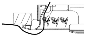
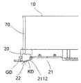
- FIG. 1 is a side cross sectional view schematically showing the entire structure of an air conditioning indoor unit according to Embodiment 1 of the present invention. It is a local-part side sectional view which shows typically the structure of the blowing panel of the air conditioning indoor unit in Embodiment 1 of this invention, Comprising: It shows the state which the wind guide fin rotated to the position which opens a blower outlet. It is a local-part side sectional view which shows typically the structure of the blowing panel of the air conditioning indoor unit in Embodiment 1 of this invention, Comprising: It shows the state which the wind guide fin rotated to the position which closes a blower outlet.
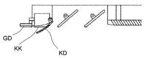
- FIG. 1 It is a local-part side sectional view which shows typically the structure of the air conditioning indoor unit in Embodiment 2 of this invention, Comprising: A wind guide fin rotates to the position which closes a blower outlet, It rotates to the position which a movable part closes an opening. Show the state of It is a local part sectional view showing typically the structure of the blowing panel of the air-conditioning indoor unit in Embodiment 2 of this invention, Comprising: A wind guide fin rotates to the position which opens a blower outlet, and a movable part opens an opening. It shows a state in which it is turned to the position to be moved. FIG.
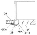
- FIG. 13 is a local side sectional view schematically showing the structure of the air conditioning indoor unit according to Embodiment 3 of the present invention, showing a state in which the wind guide fin has pivoted to a position closing the blowout port and the movable portion has risen. is there.
- FIG. 21 is a local side sectional view schematically showing the structure of the outlet panel of the air conditioning indoor unit according to Embodiment 3 of the present invention, in which the air guide fin is pivoted to the position for opening the outlet and the movable part is lowered.
- Is an indicator of It is a schematic diagram which shows the blowing effect of the airflow of the air-conditioning indoor unit in the prior art which does not contain an adhesion part, and the arrow of a thick line shows the direction of the flow of airflow.
- the actual mounting state of the air conditioning indoor unit is a state in which the case of the air conditioning indoor unit is embedded in the ceiling plate such that the case is located on the back surface of the ceiling plate and the blowout panel is exposed to the ceiling plate.
- the terms indicating directions such as “upper” and “lower” mean directions in the actual installation state of the air conditioning indoor unit, and “radially inside” and “radially outside” Both are based on the rotation axis of the fan inside the indoor unit body.
- Embodiment 1 a first embodiment of the air conditioning indoor unit according to the present invention will be described with reference to FIGS.
- the air conditioning indoor unit 1 has a case 10 and a blowing panel 20 provided below the case 10. Inside the case 10, a fan 30 is provided. An outlet 21 is formed in the outlet panel 20. A wind guide fin 40 is provided inside the air outlet 21.
- the fan 30 is attached to the top plate of the case 10 via the bracket 60. Inside the case 10, a heat exchanger 50 and a filter 70 are further provided. The heat exchanger 50 and the filter 70 are respectively provided to surround the fan 30 from the radially outer side.
- the fan 30 is an axial fan.
- the radial outer wall surface 211 has a guide portion 2111 and an adhesion portion 2112 extending from the guide portion 2111 to the outside.
- the cross-sectional shape of the guide portion 2112 cut in the vertical direction is an arc shape projecting radially inward of the blowout port 21.
- the entire cross-sectional shape of the guide portion 2112 cut in the vertical direction is an arc shape protruding inward in the radial direction of the air outlet 21.
- the cross-sectional shape obtained by cutting may be an arc shape in which at least a portion protrudes radially inward of the air outlet 21.
- the guide portion 2111 is formed of a vertical wall surface parallel to the vertical direction, and an inclined surface inclined with respect to the vertical direction. That is, the cross-sectional shape of the guide portion 2111 cut in the vertical direction is a combination of a vertical line and an inclined straight line connected to the vertical line.
- the cross-sectional shape of the attached portion 2112 cut in the vertical direction is a circular arc having a constant radius of curvature.
- the blow-out panel 20 has an outer edge frame portion 22.
- the distance H in the vertical direction between the upper portion of the outer frame portion 22 and the lower end of the attachment portion 2112 is H 10 10 mm Meet.
- the outer edge frame portion 22 has an inclined surface 221 which extends upward and radially outward from the bottom end of the blowout panel 20. Assuming that the angle between the inclined surface 221 and the horizontal surface is ⁇ , 0 ° ⁇ ⁇ 60 ° Meet.
- the air conditioning indoor unit 1 also includes a control unit 90 (see FIG. 1) including a CPU, a memory, and the like.
- the control unit 90 controls the operation of the air conditioning indoor unit 1 so that the air flow blown out from the blowout port 21 flows through the attached portion 2112 and the wind guide fins 40 and is diffused in the direction away from the blowout panel 20.
- an angle formed by an extension of a line connecting both ends in the vertical direction of the surface of the air guide fin 40 facing the guide portion 2111 and an extension line of the lower end of the guide portion 2111 Let ⁇ be ⁇ , preferably 15 ° ⁇ ⁇ ⁇ 60 ° Meet.
- the distance between the lower end of the air guide fin 40 and the lower end of the attachment portion 2112 is D, 0 mm ⁇ D ⁇ 35 mm Meet. Specifically, the lower end of the air guide fin 40 is located above the lower end of the attachment portion 2112.
- the minimum distance between the air guide fin 40 and the guide portion 2111 be L, 10 mm ⁇ L ⁇ 40 mm Meet.
- the radial outer wall surface 211 has a guide portion 2111 and an adhesion portion 2112 extending from the guide portion 2111 to the outside.
- the cross-sectional shape of the guide portion 2112 cut in the vertical direction is a vertical line.
- the cross-sectional shape of the attached portion 2112 cut in the vertical direction is an arc shape that protrudes inward in the radial direction of the air outlet 21. Therefore, as shown in FIG. 7, the air flow blown out by the action of the guide portion 2111 is smoothly derived from the blowout port 21 so that the air flow does not become turbulent in the blowout port 21, and the comfort by the blowout air flow Improve.
- the attached portion 2112 is one that smoothly extends from the guide portion 2111 to the outside. For this reason, the blowout air flow smoothly flows to the attachment portion 2112 along the guide portion 2111. Specifically, it depends on the Coanda effect.
- the entire cross-sectional shape of the attached portion 2112 cut in the vertical direction is an arc shape projecting radially inward of the air outlet 21.
- the blowout air stream first flows forward and downward due to the action of the portion of the arc shape projecting radially inward and approaching the guide portion 2111. And it flows along the direction of a ceiling board by the effect
- the air blowing effect in the cooling operation mode can be secured, and moreover, it is possible to suppress that the minute particles contained in the blowing air flow are adsorbed to the ceiling plate and the ceiling plate is soiled.
- the distance H in the vertical direction between the upper portion of the outer edge frame portion 22 and the lower end of the attachment portion 2112 is 10 mm or more.
- the distance between the ceiling plate and the lower end of the attachment portion 2112 in the vertical direction becomes 10 mm or more by bringing the upper portion of the outer rim portion 22 into contact with the ceiling plate in the mounted state of the air conditioning indoor unit.
- the blowout air flow first flows forward and downward and flows along the horizontal direction by the action of the attachment portion 2112.
- the ceiling plate is at a fixed distance.
- the air flow blown out from the air outlet 21 can be effectively prevented from flowing so as to stick to the ceiling plate, and contamination of the ceiling plate by dust contained in the blow air can be suppressed.
- the angle ⁇ between the horizontal surface and the inclined surface 221 of the outer edge frame portion 22 that extends obliquely upward and outward from the bottom end of the blowout panel 20 is 0 ° ⁇ It satisfies ⁇ ⁇ 60 °.
- the angle ⁇ is made larger than 60 °, it is possible to effectively prevent the air flow blown out from the air outlet 21 from directly hitting the ceiling plate, and the dust is included in the air flow It is suppressed that it gets dirty.
- the difference in height between the blowout panel 20 and the ceiling plate may be reduced by the visual effect, and the appearance of the combination of the blowout panel 20 and the ceiling plate can be improved.
- the air guide fin is controlled by controlling the turning angle of the air guide fin 40 so as to satisfy the condition of 15 ° ⁇ ⁇ ⁇ 60 ° during the cooling operation of the air conditioning indoor unit 1.
- An air flow passage having a tapered end is formed between 40 and the inner wall of the air outlet 21. This contributes to the formation of the main air flow by increasing the flow velocity of the air flow.
- the blowout air stream first flows forward and downward and then flows along the direction of the ceiling plate by the action of the attachment portion 2112.
- the condition that 0 mm ⁇ D ⁇ 35 mm (specifically, the lower end of the air guide fin is located above the lower end of the adhering portion) during the cooling operation of the air conditioning indoor unit 1
- the turning angle of the air guide fin 40 is controlled so as to satisfy the condition.
- the air guide fins 40 and the attachment portion 2112 cooperate with each other.
- the turning angle of the air guide fin 40 is controlled so as to satisfy the condition of 10 mm ⁇ L ⁇ 40 mm during the cooling operation of the air conditioning indoor unit 1.
- the blow-off air flows through the air flow passage formed between the air guide fins 40 and the inner side wall of the blowout port 21, the flow speed is improved, and the Coanda effect by the adhering portion 2112 is contributed.
- the rotational angle of the air guide fin 40 is controlled so as to simultaneously satisfy the relational expressions 15 ° ⁇ ⁇ ⁇ 60 °, 10 mm ⁇ L ⁇ 40 mm, 0 mm ⁇ D ⁇ 35 mm.
- the blowout air flow is first of all due to the action of the arc shape projecting radially inward and in the portion close to the guide portion 2111. It flows forward and downward. Then, it flows in the horizontal direction by the action of the portion of the arc shape projecting radially inward and away from the guide portion 2111. Then, the air blowing effect in the cooling operation mode can be secured, and furthermore, it can be suppressed that the minute particles contained in the blowing air flow are adsorbed to the ceiling plate and the ceiling plate is soiled.
- Embodiment 2 of the air conditioning indoor unit in the present invention will be described with reference to FIGS. 8 and 9.
- the present embodiment is basically the same as Embodiment 1 described above, but differs in the structure of the blowing panel.
- the blowout panel 20 has an outer rim 22.
- the outer edge frame portion 22 has a fixed portion GD fixed to the case 10 and a movable portion KD openable to the fixed portion GD.
- the movable portion KD has an attached portion 2112.
- the filter 70 is not integrally formed, and at least a portion (e.g., the portion on the left side of FIG. 8) is removable from the case 10 separately from the other portions.
- the fixed portion GD has an opening KK of a size that allows removal of (at least a part of) the filter 70.
- the movable portion KD is a movable plate rotatably provided inside the opening portion KK.
- the control unit 90 also controls the rotation of the movable portion KD.
- the control unit 90 is used to rotate the movable portion KD to a position at which the opening portion KK is opened.
- one end of the attached part 2112 away from the rotation center of the movable part KD is positioned further downward. It can be done. That is, the distance between the lower end of the attached portion 2112 and the ceiling plate is increased.
- the adhesion portion 2112 the blowout air flow is kept at a constant distance from the ceiling plate.
- the control unit 90 is used to rotate the movable portion KD to a position at which the opening portion KK is opened. This makes it easy to perform maintenance on (at least a part of) the filter 70 attached to the case 10 through the opening KK. For example, the filter 70 attached to the case 10 can be removed and cleaned, and then attached to the case 10.
- Embodiment 3 of the air conditioning indoor unit in the present invention will be described with reference to FIG. 10 and FIG.
- the present embodiment is basically the same as Embodiment 1 described above, but differs in the structure of the blowing panel.
- the blowout panel 20 has an outer rim 22.
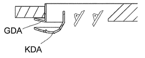
- the outer edge frame portion 22 has a fixed portion GDA fixed to the case 10 and a movable portion KDA which can move up and down with respect to the fixed portion GDA. And.
- the movable part KDA has an attached part 2112.
- the air conditioning indoor unit further includes a lifting drive mechanism.
- the elevation drive mechanism has a motor and a rack and pinion mechanism.
- the rack and pinion mechanism transmits the power of the motor to the movable part KDA, and raises and lowers the movable part KDA.
- the movable portion KDA as shown in FIG. 10 is raised by lowering the movable portion KDA using the control unit 90.
- the bottom end of the attachment portion 2112 can be positioned lower than in the case where it is carried out.
- the cross-sectional shape of the attached portion 2112 cut in the vertical direction is a circular arc having a constant radius of curvature.
- the cross-sectional shape cut along the up and down direction of the attached portion 2112 may be a shape in which a plurality of arcs having different radii of curvature are connected.
- the outer arc has a larger radius of curvature than the inner (case side) arc.
- the guide portion 2111 is formed of a vertical wall surface parallel to the vertical direction and an inclined surface inclined to the vertical direction.
- the invention is not limited thereto, and the guide portion may be formed only by an inclined surface which is inclined with respect to the vertical direction.
- 15 ° ⁇ ⁇ ⁇ 60 ° is satisfied, preferably 10 mm ⁇ L ⁇ 40 mm, and preferably 0 mm ⁇ D ⁇ 35 mm.
- the air guide fin in the heating operation mode, is inverted to preferably satisfy 0 mm ⁇ D ⁇ 35 mm, and the lower end of the air guide fin may be positioned below the adhesion portion. This contributes to guiding the air flow blown out from the fan further downward, thus achieving rapid heating. Thus, the height dimension of the blowout panel can be prevented from increasing while securing the comfort.
- the guide portion may be formed by a curved surface, or formed by at least one of a vertical wall parallel to the vertical direction and an inclined surface inclined with respect to the vertical direction and a curved surface. It may be done.
- the fan 30 is not limited to the axial fan.
Landscapes
- Engineering & Computer Science (AREA)
- Chemical & Material Sciences (AREA)
- Combustion & Propulsion (AREA)
- Mechanical Engineering (AREA)
- General Engineering & Computer Science (AREA)
- Air-Flow Control Members (AREA)
- Air Filters, Heat-Exchange Apparatuses, And Housings Of Air-Conditioning Units (AREA)
Abstract
空調室内機は、ケース(10)及びその下方に設けられた吹出しパネル(20)を備える。この空調室内機では、吹出しパネル(20)に設けられた吹出口(21)から吹き出された気流が天井板に直接当たること、が避けられる。ケース(10)の内部にはファン(30)が設けられる。吹出しパネル(20)に形成された吹出口(21)の内部には、導風フィン(40)が設けられる。吹出しパネル(20)の、吹出口(21)を構成する壁面のうち、径方向外側壁面(211)は、案内部(2111)と、その案内部(2111)から外部へ延伸する付着部(2112)と、を有する。案内部(2111)の断面形状は、鉛直線と、傾斜直線と、吹出口(21)の径方向外側に向かって突出した弧形状とのうちの少なくとも1つである。付着部(2112)の断面形状は、少なくとも一部が、吹出口(21)の径方向内側に向かって突出した弧形状である。
Description
本発明は、空調室内機に関する。
従来、図12に示すように、ケース10Xと、ケース10Xの下方に設けられた吹出しパネル20Xとを備え、ケース10Xの内部にファンが設けられ、吹出しパネル20Xに吹出口CFXが形成され、その吹出口CFXの内部に導風フィン40Xが設けられている空調室内機が存在している。
しかし、図12に示すように、上記空調室内機は、ケース10Xが天井板Uの裏面に位置し、吹出しパネル20Xが天井板Uに露出するように天井板Uに埋め込まれている場合、運転されると、特に、冷房で運転されると、吹出口CFXから吹き出された気流が天井板Uに張り付くように流れ、運転時間の経過に伴い、吹出口CFXから吹き出された気流に含まれる埃などが吹出しパネル20Xの周囲の天井板Uに付着やすくなり、天井板Uが汚れてしまう。
本発明は、上記問題に鑑みて為されたものであり、ケース及び当該ケースの下方に設けられた吹出しパネルを備える空調室内機であって、吹出しパネルに設けられた吹出口から吹き出された気流が天井板に直接当たることを避けることに寄与する空調室内機を提供することを目的としている。
上記の技術的課題を解決するために、本発明は、ケースと当該ケースの下方に設けられた吹出しパネルとを備える空調室内機であって、ケースと吹出しパネルとで囲まれた空間内に、ファンが設けられている。吹出しパネルには、吹出口が形成されている。吹出口の内部には、導風フィンが設けられている。吹出しパネルの吹出口を構成する壁面のうち、径方向外側壁面は、案内部と、その案内部から外部へ延伸する付着部と、を有している。案内部の上下方向に沿って切断した断面形状は、鉛直線と、傾斜直線と、吹出口の径方向外側に向かって突出した弧形状との少なくとも1つである。付着部の上下方向に沿って切断した断面形状は、少なくとも一部が、吹出口の径方向内側に向かって突出した弧形状である。
本発明における空調室内機によれば、案内部による作用で、気流が吹出口の内部に乱流にならないように、吹き出された気流を吹出口からスムーズに導出でき、吹き出し気流による快適性が向上する。さらに、吹出し気流は、案内部から付着部に滑らかに移行することが可能であり、付着部によるコアンダ効果により、吹出し気流が付着部の表面から離れにくくなり、吹出し気流の流れの方向を変化させる。特に、吹出口の径方向内側に向かって突出した弧形状による作用で、吹出し気流はまず前且つ下方に向かって拡散し、そして、天井板の方向に沿って流れるようになる。これによって、吹出口から吹き出された気流が天井板に張り付くように流れることを効果的に避けることができ、吹出口から吹き出された気流が天井板に直接当たることを避けることにも寄与し、天井板が吹き出し気流に含まれる埃によって汚れてしまうことを抑制する。
本発明では、好ましくは、吹出しパネルは、外縁枠部を有し、外縁枠部の上部と付着部の下端との間の上下方向の距離は、10mm以上である。
上記構造を有する空調室内機によれば、上下方向において、外縁枠部の上部と付着部の下端との間の距離が10mm以上であるため、空調室内機の取り付け状態で、外縁枠部の上部を上下方向において天井板に当接させることにより、上下方向において天井板と付着部の下端との距離が10mm以上に達する。これによって、上記距離を10mmよりも小さくした場合と比べて、吹出口から吹き出された気流が天井板に張り付くように流れることをより効果的に避けることができ、天井板が吹き出し気流に含まれる埃によって汚れてしまうことが抑制される。
本発明では、好ましくは、吹出しパネルは、外縁枠部を有する。外縁枠部は、吹出しパネルの底端から径方向外側に向かって上向きに傾斜して延伸する傾斜面を有し、その傾斜面と水平面とのなす角度をγとすると、
0°<γ≦60°
を満たす。
0°<γ≦60°
を満たす。
上記構造を有する空調室内機によれば、上記の角度γを60°よりも大きくした場合と比べて、吹出口から吹き出された気流が天井板に直接当たることを効果的に避けることができ、天井板が吹き出し気流に含まれる埃によって汚れてしまうことを抑制するとともに、吹出しパネルと天井板との組み合わせの見栄えを向上させることができる。
本発明では、好ましくは、付着部の上下方向に沿って切断した断面形状が、曲率半径が異なる複数の円弧によって接続された形状である。
上記構造を有する空調室内機によれば、円弧の数を適宜設定することにより、複数の円弧を利用して壁付着気流の流れの方向を徐々に変化させることができる。壁付着気流が付着部から剥離してしまうことを抑制し、コアンダ効果を高めることに寄与する。吹出口から吹き出された気流が天井板に直接当たることを避け、天井板が吹き出し気流に含まれる埃によって汚れてしまうことを抑制する。
本発明では、好ましくは、付着部の曲率半径が異なる複数の円弧のうち、外側の円弧は、内側の円弧よりも、曲率半径が大きくなる。
上記構造を有する空調室内機によれば、外側の円弧が、内側となる円弧よりも、曲率半径が大きくなることにより、壁付着気流の流れの方向の変化程度を徐々に向上させることができ、壁付着気流が付着部から剥離してしまうことを抑制し、コアンダ効果を高めることに寄与する。吹出口から吹き出された気流が天井板に直接当たることが避けられ、天井板が吹き出し気流に含まれる埃によって汚れてしまうことが抑制される。
本発明では、好ましくは、吹出しパネルは、外縁枠部を有する。外縁枠部は、ケースに固定された固定部と、固定部に対して開放可能な可動部とを有する。可動部は、付着部を有する。
上記構造を有する空調室内機によれば、可動部の回動中心から離れた付着部の一端をより下方に位置させる箇所まで、可動部を回動させる。このことは、付着部を下向きに延伸させることに相当する。これによって、吹出口から吹き出された気流が天井板に直接当たることをより効果的に避けることができ、天井板が吹き出し気流に含まれる埃によって汚れてしまうことが抑制される。
本発明では、好ましくは、ケースには、フィルターが設けられている。固定部は、フィルターが取り出されることが可能なサイズを有する開口部を備える。可動部は、開口部の内部に回動可能に設けられた可動板である。
上記構造を有する空調室内機によれば、空調室内機の運転時、可動部を、開口部を開放させる位置まで回動させることにより、開口部を介してケースに取り付けられたフィルターに対して、メンテナンスを行いやすくなる。例えば、ケースに取り付けられたフィルターを取り外して、洗浄し、その後、ケースに取り付けることができる。
本発明では、好ましくは、吹出しパネルは、外縁枠部を有する。外縁枠部は、ケースに固定された固定部と、固定部に対して昇降可能な可動部とを有する。可動部は、付着部を有する。
上記構造を有する空調室内機によれば、空調室内機の運転時、可動部を下降させることにより、可動部を上昇させる場合と比べて、付着部の底端をより下方に位置させることができる。これによって、吹出口から吹き出された気流が天井板に直接当たることをより効果的に避けることができ、天井板が吹き出し気流に含まれる埃によって汚れてしまうことが抑制される。
本発明では、好ましくは、空調室内機は、昇降駆動機構をさらに備える。昇降駆動機構は、モータと、ラックピニオン機構とを含む。ラックピニオン機構は、可動部を昇降させるように、モータによる動力を可動部に伝達する。
上記構造を有する空調室内機によれば、可動部の昇降を簡単な構成で実現させることができ、製造のコストを低減することに寄与する。
本発明では、好ましくは、ファンは軸流ファンである。
本発明では、空調室内機は、制御部を備える。制御部は、吹出口から吹き出された気流が、付着部と導風フィンを流れて吹出しパネルから離れる方向へ拡散するように、空調室内機の運転を制御する。
上記構造を有する空調室内機によれば、付着部と導風フィンとの協働作用で、吹出し気流が吹出しパネルから離れる方向へ拡散するようになり、吹出口から吹き出された気流が天井板に直接当たることをより効果的に避けることができ、天井板が吹き出し気流に含まれる埃によって汚れてしまうことが抑制される。
本発明では、好ましくは、冷房運転モードにおいて、導風フィンの案内部に面する面の上下方向の両端を結ぶ線の延長線と、案内部の下端の延長線とのなす角度をαとすると、
15°≦α≦60°
を満たす。
15°≦α≦60°
を満たす。
上記構造を有する空調室内機によれば、空調室内機の運転時、15°≦α≦60°という条件を満たすように、導風フィンの回動角度が制御される。これにより、αを他の角度とする場合と比べて、吹出口から吹き出された気流が天井板に直接当たることを効果的に避けることができる。
本発明では、好ましくは、冷房運転モードにおいて、導風フィンと案内部との最小距離をLとすると、
10mm≦L≦40mm
を満たす。
10mm≦L≦40mm
を満たす。
上記構造を有する空調室内機によれば、空調室内機の運転時、10mm≦L≦40mmという条件を満たすように、導風フィンの回動角度を制御する。これにより、Lを他の角度とする場合と比べて、付着部によるコアンダ効果を確保することに寄与し、送風量を確保することもできる。
本発明では、好ましくは、付着部の上下方向に沿って切断した断面において、付着部の両端を結ぶ線から最も離れた付着部の点における接線と、水平面とのなす角度をβとすると、
0°<β≦60°
を満たす。
0°<β≦60°
を満たす。
上記構造を有する空調室内機によれば、コアンダ効果を高めることに寄与する。
本発明では、好ましくは、冷房運転モードにおいて、導風フィンの下端と付着部の下端との距離をDとすると、
0mm≦D≦35mm
を満たす。
0mm≦D≦35mm
を満たす。
上記構造を有する空調室内機によれば、コアンダ効果を高めることに寄与する。
以下、添付図面を参照しながら、空調室内機の実際な取り付け状態に応じて、本発明における空調室内機の実施の形態を説明する。ここで、空調室内機の実際な取り付け状態とは、空調室内機は、ケースが天井板の裏面に位置し、吹き出しパネルが天井板に露出したように、天井板に埋め込まれた状態である。
ところで、本願では、「上」、「下」などの方向を示す用語は、いずれも空調室内機の実際な取り付け状態での方向を意味しており、「径方向内側」と「径方向外側」はともに、室内機本体の内部におけるファンの回転軸線を基準としているものである。
<実施の形態1>
以下、図1~7を参照しながら、本発明における空調室内機の実施の形態1を説明する。
以下、図1~7を参照しながら、本発明における空調室内機の実施の形態1を説明する。
図1に示すように、空調室内機1は、ケース10と、ケース10の下方に設けられた吹出しパネル20とを有する。ケース10の内部に、ファン30が設けられている。吹出しパネル20には、吹出口21が形成されている。吹出口21の内部に、導風フィン40が設けられている。
ここで、ファン30は、ブラケット60を介してケース10の天板に取り付けられている。ケース10の内部には、さらに、熱交換器50とフィルター70とが設けられている。熱交換器50とフィルター70は、それぞれ、径方向外側からファン30を囲むように設けられている。ここでは、ファン30は軸流ファンである。
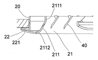
また、図2に示すように、吹出しパネル20の吹出口21を構成する壁面のうち、径方向外側壁面211は、案内部2111と、案内部2111から外部へ伸びる付着部2112と、を有する。案内部2112の上下方向に沿って切断した断面形状は、吹出口21の径方向内側に向かって突出した弧形状である。ここでは、案内部2112の上下方向に沿って切断した断面形状全体が、吹出口21の径方向内側に向かって突出した弧形状であるが、これに限らず、付着部2112の上下方向に沿って切断した断面形状は、少なくとも一部が、吹出口21の径方向内側に向かって突出した弧形状であればよい。
図2と図3に示すように、案内部2111は、上下方向に平行な鉛直壁面と、上下方向に対して傾斜した傾斜面と、で形成されている。即ち、案内部2111の上下方向に沿って切断した断面形状は、鉛直線と、鉛直線に接続された傾斜直線と、が組み合わされたものである。付着部2112の上下方向に沿って切断した断面形状は、曲率半径が一定な円弧である。
また、図2と図3に示すように、吹出しパネル20は、外縁枠部22を有する。外縁枠部22の上部と、付着部2112の下端との間の上下方向の距離Hは、
H≧10mm
を満たす。
H≧10mm
を満たす。
また、図3に示すように、外縁枠部22は、吹出しパネル20の底端から、径方向外側に向かって上向きに傾斜して伸びる傾斜面221を有する。傾斜面221と水平面とのなす角度をγとすると、
0°<γ≦60°
を満たす。
0°<γ≦60°
を満たす。
また、本実施の形態では、空調室内機1は、CPUやメモリーなどから成る制御部90(図1参照)も備えている。制御部90は、吹出口21から吹き出された気流が、付着部2112と導風フィン40とを流れて、吹出しパネル20から離れる方向へ拡散するように、空調室内機1の運転を制御する。
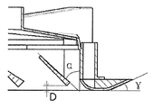
また、図4に示すように、冷房運転モードでは、案内部2111に面する導風フィン40の面の上下方向の両端を結ぶ線の延長線と、案内部2111の下端の延長線のなす角度をαとすると、好ましくは、
15°≦α≦60°
を満たす。
15°≦α≦60°
を満たす。
さらに、冷房運転モードでは、導風フィン40の下端と付着部2112の下端との距離をDとすると、
0mm≦D≦35mm
を満たす。具体的には、導風フィン40の下端は、付着部2112の下端の上方に位置する。
0mm≦D≦35mm
を満たす。具体的には、導風フィン40の下端は、付着部2112の下端の上方に位置する。
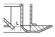
また、図5に示すように、冷房運転モードでは、導風フィン40と案内部2111との最小距離をLとすると、好ましくは、
10mm≦L≦40mm
を満たす。
10mm≦L≦40mm
を満たす。
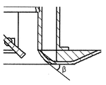
また、図6に示すように、本実施の形態では、付着部2112の上下方向に沿って切断した断面において、付着部2112の上下両端を結ぶ線から最も離れている付着部2112の点における接線LQと、水平面と、のなす角度をβとすると、
0°<β≦60°
を満たす。
0°<β≦60°
を満たす。
本実施の形態によれば、吹出しパネル20の吹出口21を構成する壁面のうち、径方向外側壁面211は、案内部2111と、案内部2111から外部へ伸びる付着部2112と、を有する。案内部2112の上下方向に沿って切断した断面形状は、鉛直線である。付着部2112の上下方向に沿って切断した断面形状は、吹出口21の径方向内側に向かって突出した弧形状である。そのため、図7に示すように、案内部2111による作用で、吹き出された気流は、気流が吹出口21内において乱流にならないように、吹出口21からスムーズに導出され、吹き出し気流による快適性を向上させる。
さらに、付着部2112は、案内部2111から外部へ滑らかに延伸するものである。このため、吹出し気流は、案内部2111に沿って、付着部2112に滑らかに流れるようになる。具体的には、コアンダ効果による。付着部2112の上下方向に沿って切断した断面形状全体は、吹出口21の径方向内側に向かって突出した弧形状である。吹出し気流は、上記径方向内側へ突出した弧形状の、案内部2111に接近した部分による作用で、まず前方且つ下方に向かって流れる。そして、上記径方向内側へ突出した弧形状の、案内部2111から離れた部分による作用で、天井板の方向に沿って流れる。これによって、冷房運転モードでの送風効果を確保することができるほか、吹出し気流に含まれる微小な粒子が天井板に吸着して天井板が汚れてしまうことを抑制することができる。
また、本実施の形態によれば、外縁枠部22の上部と付着部2112の下端との間の上下方向の距離Hが、10mm以上となっている。このため、空調室内機の取り付け状態で外縁枠部22の上部を天井板に当接させることにより、上下方向において天井板と付着部2112の下端との距離が10mm以上になる。これによって、吹出し気流は、付着部2112による作用で、まず前方且つ下方に向かって流れ、そして、水平方向に沿って流れるようになる。気流が上下方向において拡散してしまった場合でも、天井板とは一定の距離を置いていることになる。これによって、吹出口21から吹き出された気流が天井板に張り付くように流れることを効果的に避けることができ、天井板が吹き出し気流に含まれる埃によって汚れてしまうことが抑制される。
また、本実施の形態によれば、外縁枠部22の、吹出しパネル20の底端から径方向外側に向かって上向きに傾斜して延伸する傾斜面221と水平面のなす角度γが、0°<γ≦60°を満たす。これによって、角度γを60°よりも大きくする場合と比べると、吹出口21から吹き出された気流が天井板に直接当たることを効果的に避けることができ、天井板が吹き出し気流に含まれる埃によって汚れてしまうことが抑制される。また、傾斜面221によっては、視覚効果によって吹出しパネル20と天井板との高度差が減り、吹出しパネル20と天井板との組み合わせの見栄えを向上させることができる。
また、本実施の形態によれば、空調室内機1の冷房運転時、15°≦α≦60°という条件を満たすように、導風フィン40の回動角度を制御することにより、導風フィン40と吹出口21の内側壁との間に、先が細くなる気流通路が形成される。このことは、気流の流動速度を高めて主気流を形成することに寄与する。吹出し気流は、付着部2112による作用で、まず、前方且つ下方に流れ、そして、天井板の方向に沿って流れるようになる。
また、本実施の形態によれば、空調室内機1の冷房運転時、0mm≦D≦35mm(具体的には、導風フィンの下端は、付着部の下端の上方に位置する)という条件を満たすように、導風フィン40の回動角度を制御する。これにより、導風フィン40と付着部2112とが相互に協働するようになる。
また、本実施の形態によれば、空調室内機1の冷房運転時、10mm≦L≦40mmという条件を満たすように、導風フィン40の回動角度を制御する。これにより、吹出し気流は、導風フィン40と吹出口21の内側壁との間に形成された気流通路を流れ、流動速度が向上し、付着部2112によるコアンダ効果を確保することに寄与する。
特に、空調室内機1の冷房運転時、15°≦α≦60°、10mm≦L≦40mm、0mm≦D≦35mmという各関係式を同時に満たすように、導風フィン40の回動角度を制御することによって、吹出口21から吹き出された気流が天井板に直接当たることを効果的に避けることができる。また、気流が直下に吹き出されることを抑制できる。さらに、コアンダ効果により、吹出し気流がまず前方且つ下方に向かって流れ、そして、水平方向に流れることが確保される。これにより、送風量が確保され、快適性が向上する。
また、本実施の形態によれば、0°<β≦60°を満たしているので、吹出し気流は、径方向内側へ突出した弧形状の、案内部2111に接近した部分による作用で、まず、前方且つ下方に向かって流れる。そして、径方向内側へ突出した弧形状の、案内部2111から離れた部分による作用で、水平方向へ流れる。そうすると、冷房運転モードでの送風効果を確保することができ、さらに、吹出し気流に含まれる微小な粒子が天井板に吸着されて天井板が汚れてしまうことも抑制できる。
<実施の形態2>
以下、図8と図9を参照しながら、本発明における空調室内機の実施の形態2を説明する。本実施の形態は、上記実施の形態1と基本的に同じであるが、吹出しパネルの構造が相違する。
以下、図8と図9を参照しながら、本発明における空調室内機の実施の形態2を説明する。本実施の形態は、上記実施の形態1と基本的に同じであるが、吹出しパネルの構造が相違する。
ここでは、上記実施の形態1と同じ部材に対して同一の符号を付加し、相違点を中心として説明する。
図8に示すように、吹出しパネル20は、外縁枠部22を有する。外縁枠部22は、ケース10に固定された固定部GDと、固定部GDに対して開放可能な可動部KDとを有する。可動部KDは、付着部2112を有する。
また、フィルター70は、一体に形成されたものではなく、少なくとも一部(例えば、図8の左側の部分)が、他の部分とは別に、ケース10から取り外し可能である。
また、固定部GDは、フィルター70(の少なくとも一部)の取り出しが可能なサイズの開口部KKを有する。
ここで、可動部KDは、開口部KKの内部に回動可能に設けられた可動板である。
また、制御部90は、可動部KDの回動を制御する。
本実施の形態によれば、基本的に上記実施の形態と同じ技術的効果を奏することができる。
また、本実施の形態によれば、空調室内機の運転時、図9に示すように、制御部90を用いて、開口部KKを開放させる位置まで可動部KDを回動させる。これにより、図8に示すような、開口部KKを閉じる位置に可動部KDが位置する場合と比べて、付着部2112の、可動部KDの回動中心から離れた一端を、より下方に位置させることができる。即ち、付着部2112の下端と天井板との距離が増加する。付着部2112による作用で、吹出し気流は、天井板との間で一定の距離を保つことになる。これによって、吹出口21から吹き出された気流が天井板に直接当たることをより効果的に避けることができ、天井板が吹き出し気流に含まれるダストによって汚れてしまうことが抑制される。
また、本実施の形態によれば、空調室内機の運転時、図9に示すように、制御部90を用いて、開口部KKを開放させる位置まで可動部KDを回動させる。これにより、開口部KKを介して、ケース10に取り付けられたフィルター70(の少なくとも一部)へのメンテナンスが行いやすくなる。例えば、ケース10に取り付けられたフィルター70を取り外して洗浄し、その後、ケース10に取り付けることができる。
<実施の形態3>
以下、図10と図11を参照しながら、本発明における空調室内機の実施の形態3を説明する。本実施の形態は、上記実施の形態1と基本的に同じであるが、吹出しパネルの構造が相違する。
以下、図10と図11を参照しながら、本発明における空調室内機の実施の形態3を説明する。本実施の形態は、上記実施の形態1と基本的に同じであるが、吹出しパネルの構造が相違する。
ここでは、上記実施の形態と同じ部材に対して同一の符号を付加し、相違点を中心として説明する。
図10に示すように、吹出しパネル20は、外縁枠部22を有する。外縁枠部22は、ケース10に固定された固定部GDAと、固定部GDAに対して昇降可能な可動部KDA
とを有する。可動部KDAは、付着部2112を有する。
とを有する。可動部KDAは、付着部2112を有する。
ここで、図示されていないが、空調室内機は、昇降駆動機構をさらに備える。昇降駆動機構は、モータと、ラックピニオン機構とを有する。ラックピニオン機構は、モータによる動力を可動部KDAに伝達し、その可動部KDAを昇降させる。
本実施の形態によれば、基本的に上記実施の形態と同じ技術的効果を奏することができる。
また、本実施の形態によれば、空調室内機の運転時、図11に示すように、制御部90を用いて可動部KDAを下降させることにより、図10に示すような可動部KDAが上昇している場合と比べて、付着部2112の底端を、より下方に位置させることができる。これによって、吹出口21から吹き出された気流が天井板に直接当たることを、より効果的に避けることができる。
以上、添付図面によって、本発明を例示的に説明したが、本発明の具体的な実現は、上記実施の形態だけに限られないことは明らかである。
例えば、上記実施の形態では、付着部2112の上下方向に沿って切断した断面形状が、曲率半径が一定な円弧である。しかし、そのような断面形状に限らず、付着部2112の上下方向に沿って切断した断面形状は、曲率半径が異なる複数の円弧が接続された形状であってもよい。また、その場合、好ましくは、複数の円弧のうち、外側の円弧は、内側(ケース側)の円弧よりも、曲率半径が大きくなる。そのような構造によれば、吹出口21から吹き出された気流が天井板に直接当たることを、より効果的に避けることができる。
また、上記実施の形態では、案内部2111は、上下方向に平行な鉛直壁面と上下方向に対して傾斜した傾斜面とで形成されている。しかし、それに限らず、案内部は、上下方向に対して傾斜した傾斜面のみで形成されてもよい。その場合、付着部と導風フィンとが協働して、ファンから吹き出された気流を、付着部に沿って径方向外側に案内するような冷房運転モードにおいて、上記実施の形態と同じように、好ましくは、15°≦α≦60°を満たし、好ましくは、10mm≦L≦40mmを満たし、好ましくは、0mm≦D≦35mmを満たす。
また、上記実施の形態において、暖房運転モードでは、導風フィンが反転され、0mm≦D≦35mmを満たすことが好ましく、導風フィンの下端が付着部の下方に位置するようにしてもよい。そうすると、ファンから吹き出された気流を、さらに下向きに案内させることに寄与し、迅速な加熱を実現する。これにより、快適性を確保しながら、吹出しパネルの高さ寸法を増加しないようにすることができる。
また、図示されていないが、案内部は、曲面で形成されてもよいし、または、上下方向に平行な鉛直壁面と、上下方向に対して傾斜した傾斜面との、少なくとも一方及び曲面で形成されてもよい。
また、ファン30は、軸流ファンに限られない。
1 空調室内機
10 ケース
20 吹出しパネル
21 吹出口
22 外縁枠部
221 傾斜面
211 径方向外側壁面
2111 案内部
2112 付着部
30 ファン
40 導風フィン
50 熱交換器
60 ブラケット
70 フィルター
GD,GDA 固定部
KK 開口部
KD,KDA 可動部
10 ケース
20 吹出しパネル
21 吹出口
22 外縁枠部
221 傾斜面
211 径方向外側壁面
2111 案内部
2112 付着部
30 ファン
40 導風フィン
50 熱交換器
60 ブラケット
70 フィルター
GD,GDA 固定部
KK 開口部
KD,KDA 可動部
Claims (13)
- ケース(10)と、
前記ケースの下方に設けられた吹出しパネル(20)と、
前記ケースの内部に設けられたファン(30)と、
導風フィン(40)と、
を備える空調室内機であって、
前記吹出しパネルに、吹出口(21)が形成されており、
前記吹出口の内部に、前記導風フィンが設けられ、
前記吹出しパネルの、前記吹出口を構成する壁面のうち、径方向外側壁面(211)は、案内部(2111)と、前記案内部から外部へ延伸する付着部(2112)と、を有し、
前記案内部(2111)の上下方向に沿って切断した断面形状は、鉛直線と、傾斜直線と、前記吹出口の径方向外側に向かって突出した弧形状とのうちの少なくとも1つであり、
前記付着部(2112)の上下方向に沿って切断した断面形状は、少なくとも一部が、前記吹出口の径方向内側に向かって突出した弧形状である、
空調室内機。
- 前記吹出しパネル(20)は、外縁枠部(22)を有し、
上下方向において、前記外縁枠部(22)の上部と前記付着部(2112)の下端との間の上下方向の距離は、10mm以上である、
請求項1に記載の空調室内機。
- 前記吹出しパネル(20)は、外縁枠部(22)を有し、
前記外縁枠部(22)は、前記吹出しパネルの底端から径方向外側に向かって上向きに傾斜して延伸する傾斜面(221)を有し、
前記傾斜面(221)と水平面とのなす角度をγとすると、
0°<γ≦60°
を満たす、
請求項1又は2に記載の空調室内機。
- 前記付着部(2112)の上下方向に沿って切断した断面形状は、曲率半径が異なる複数の円弧が接続された形状である、
請求項1から3のいずれか1項に記載の空調室内機。
- 前記複数の円弧において、外側の円弧は、内側の円弧よりも、曲率半径が大きい、
請求項4に記載の空調室内機。
- 前記付着部(2112)は、可動的なものである、
請求項1から5のいずれか1項に記載の空調室内機。
- 前記ファン(30)は、軸流ファンである、
請求項1から6のいずれか1項に記載の空調室内機。
- 前記空調室内機は、制御部(90)を備え、
前記制御部は、前記吹出口から吹き出された気流が、前記付着部と前記導風フィンとを流れて、前記吹出しパネルから離れる方向へ拡散するように、前記空調室内機の運転を制御する、
請求項1から7のいずれか1項に記載の空調室内機。
- 冷房運転モードにおいて、前記導風フィン(40)の前記案内部(2111)に面する面の上下方向の両端を結ぶ線の延長線と、前記案内部(2111)の下端の延長線とのなす角度をαとすると、
15°≦α≦60°
を満たす、
請求項8に記載の空調室内機。
- 冷房運転モードにおいて、前記導風フィン(40)と前記案内部(2111)との最小距離をLとすると、
10mm≦L≦40mm
を満たす、
請求項8又は9に記載の空調室内機。
- 前記付着部(2112)を上下方向に沿って切断した断面において、前記付着部の両端を結ぶ線から最も離れた前記付着部の点における接線と、水平面とのなす角度をβとすると、
0°<β≦60°
を満たす、
請求項1から10のいずれか1項に記載の空調室内機。
- 運転モードにおいて、前記導風フィンの下端と前記付着部の下端との距離をDとすると、
0mm≦D≦35mm
を満たす、
請求項8から10のいずれか1項に記載の空調室内機。
- 運転モードにおいて、前記導風フィンの下端は、前記付着部の下端の上方に位置する、請求項8から10のいずれか1項、又は、請求項12に記載の空調室内機。
Applications Claiming Priority (4)
| Application Number | Priority Date | Filing Date | Title |
|---|---|---|---|
| CN201720740183.X | 2017-06-23 | ||
| CN201710488739.5 | 2017-06-23 | ||
| CN201710488739.5A CN109114687B (zh) | 2017-06-23 | 2017-06-23 | 空调室内机 |
| CN201720740183.XU CN207132443U (zh) | 2017-06-23 | 2017-06-23 | 空调室内机 |
Publications (1)
| Publication Number | Publication Date |
|---|---|
| WO2018235946A1 true WO2018235946A1 (ja) | 2018-12-27 |
Family
ID=64736023
Family Applications (1)
| Application Number | Title | Priority Date | Filing Date |
|---|---|---|---|
| PCT/JP2018/023837 Ceased WO2018235946A1 (ja) | 2017-06-23 | 2018-06-22 | 空調室内機 |
Country Status (1)
| Country | Link |
|---|---|
| WO (1) | WO2018235946A1 (ja) |
Cited By (2)
| Publication number | Priority date | Publication date | Assignee | Title |
|---|---|---|---|---|
| CN110748955A (zh) * | 2019-11-14 | 2020-02-04 | 珠海格力电器股份有限公司 | 空调室内机 |
| CN114763927A (zh) * | 2021-01-15 | 2022-07-19 | 青岛海尔空调器有限总公司 | 立式空调室内机 |
Citations (6)
| Publication number | Priority date | Publication date | Assignee | Title |
|---|---|---|---|---|
| JPH10160238A (ja) * | 1996-11-29 | 1998-06-19 | Mitsubishi Electric Corp | 埋め込み形空気調和装置 |
| JP2001193960A (ja) * | 1999-11-05 | 2001-07-17 | Daikin Ind Ltd | 天井埋込型空気調和装置 |
| EP1471311A1 (en) * | 2003-04-22 | 2004-10-27 | Xiang Srl | Ceiling type air-conditioner |
| EP1589292A1 (en) * | 2004-04-23 | 2005-10-26 | Unico Consumer Products Co., Ltd. | Ceiling-recessed air treatment apparatus |
| JP2007292328A (ja) * | 2006-04-21 | 2007-11-08 | Daikin Ind Ltd | 空気調和装置 |
| CN106678982A (zh) * | 2017-02-16 | 2017-05-17 | 珠海格力电器股份有限公司 | 出风面板及具有其的空调装置 |
-
2018
- 2018-06-22 WO PCT/JP2018/023837 patent/WO2018235946A1/ja not_active Ceased
Patent Citations (6)
| Publication number | Priority date | Publication date | Assignee | Title |
|---|---|---|---|---|
| JPH10160238A (ja) * | 1996-11-29 | 1998-06-19 | Mitsubishi Electric Corp | 埋め込み形空気調和装置 |
| JP2001193960A (ja) * | 1999-11-05 | 2001-07-17 | Daikin Ind Ltd | 天井埋込型空気調和装置 |
| EP1471311A1 (en) * | 2003-04-22 | 2004-10-27 | Xiang Srl | Ceiling type air-conditioner |
| EP1589292A1 (en) * | 2004-04-23 | 2005-10-26 | Unico Consumer Products Co., Ltd. | Ceiling-recessed air treatment apparatus |
| JP2007292328A (ja) * | 2006-04-21 | 2007-11-08 | Daikin Ind Ltd | 空気調和装置 |
| CN106678982A (zh) * | 2017-02-16 | 2017-05-17 | 珠海格力电器股份有限公司 | 出风面板及具有其的空调装置 |
Cited By (2)
| Publication number | Priority date | Publication date | Assignee | Title |
|---|---|---|---|---|
| CN110748955A (zh) * | 2019-11-14 | 2020-02-04 | 珠海格力电器股份有限公司 | 空调室内机 |
| CN114763927A (zh) * | 2021-01-15 | 2022-07-19 | 青岛海尔空调器有限总公司 | 立式空调室内机 |
Similar Documents
| Publication | Publication Date | Title |
|---|---|---|
| WO2016197747A1 (zh) | 空调器 | |
| WO2017041728A1 (zh) | 立式空调器及其使用方法 | |
| JPWO2004040204A1 (ja) | 空気調和装置の室内機 | |
| JP5223976B2 (ja) | 空調室内機 | |
| CN107278255A (zh) | 空调的室内机 | |
| WO2011033843A1 (ja) | 空気調節装置の風向変更装置 | |
| JP5080210B2 (ja) | 空気調和機 | |
| JP5348294B2 (ja) | 空調室内機 | |
| JP2015155764A (ja) | 空気調和装置の室内機 | |
| JP2017116146A (ja) | 空気調和装置の室内ユニット | |
| JP2017116146A5 (ja) | ||
| CN1342873A (zh) | 空调装置的装饰板、送风口单元及空调装置 | |
| CN109163387A (zh) | 一种用于空调室外机的气流反向结构及空调室外机 | |
| JP4858506B2 (ja) | 空気調和装置 | |
| CN104685302A (zh) | 空调机 | |
| CN206618021U (zh) | 制冷空调内机及其导风板结构和空调 | |
| WO2001035030A1 (en) | Ceiling-embedded type air conditioner | |
| CN109114687A (zh) | 空调室内机 | |
| WO2022151800A1 (zh) | 立式空调室内机 | |
| JP2017116145A (ja) | 空気調和装置の室内ユニット | |
| CN104390266B (zh) | 挂壁式空调器 | |
| CN219325716U (zh) | 车辆及车辆出风结构 | |
| CN215980030U (zh) | 风压式排气结构及排风扇 | |
| CN106871239B (zh) | 制冷空调内机及其导风板结构和导风控制方法 | |
| CN207132443U (zh) | 空调室内机 |
Legal Events
| Date | Code | Title | Description |
|---|---|---|---|
| 121 | Ep: the epo has been informed by wipo that ep was designated in this application |
Ref document number: 18821365 Country of ref document: EP Kind code of ref document: A1 |
|
| NENP | Non-entry into the national phase |
Ref country code: DE |
|
| 122 | Ep: pct application non-entry in european phase |
Ref document number: 18821365 Country of ref document: EP Kind code of ref document: A1 |
|
| NENP | Non-entry into the national phase |
Ref country code: JP |