WO2018235496A1 - 電力制御装置及び発電装置 - Google Patents
電力制御装置及び発電装置 Download PDFInfo
- Publication number
- WO2018235496A1 WO2018235496A1 PCT/JP2018/019678 JP2018019678W WO2018235496A1 WO 2018235496 A1 WO2018235496 A1 WO 2018235496A1 JP 2018019678 W JP2018019678 W JP 2018019678W WO 2018235496 A1 WO2018235496 A1 WO 2018235496A1
- Authority
- WO
- WIPO (PCT)
- Prior art keywords
- power
- electronic device
- threshold
- current
- external interface
- Prior art date
- Legal status (The legal status is an assumption and is not a legal conclusion. Google has not performed a legal analysis and makes no representation as to the accuracy of the status listed.)
- Ceased
Links
Images




Classifications
-
- G—PHYSICS
- G06—COMPUTING OR CALCULATING; COUNTING
- G06F—ELECTRIC DIGITAL DATA PROCESSING
- G06F1/00—Details not covered by groups G06F3/00 - G06F13/00 and G06F21/00
- G06F1/26—Power supply means, e.g. regulation thereof
-
- G—PHYSICS
- G06—COMPUTING OR CALCULATING; COUNTING
- G06F—ELECTRIC DIGITAL DATA PROCESSING
- G06F1/00—Details not covered by groups G06F3/00 - G06F13/00 and G06F21/00
- G06F1/26—Power supply means, e.g. regulation thereof
- G06F1/30—Means for acting in the event of power-supply failure or interruption, e.g. power-supply fluctuations
-
- H—ELECTRICITY
- H02—GENERATION; CONVERSION OR DISTRIBUTION OF ELECTRIC POWER
- H02J—ELECTRIC POWER NETWORKS; CIRCUIT ARRANGEMENTS OR SYSTEMS FOR SUPPLYING OR DISTRIBUTING ELECTRIC POWER; SYSTEMS FOR STORING ELECTRIC ENERGY
- H02J7/00—Circuit arrangements for charging or discharging batteries or for supplying loads from batteries
- H02J7/34—Parallel operation in networks using both storage and other DC sources, e.g. providing buffering
- H02J7/35—Parallel operation in networks using both storage and other DC sources, e.g. providing buffering with light sensitive cells
Definitions
- the present invention relates to a power control device and a power generation device.
- a portable electronic device such as a smartphone, a notebook PC (Personal Computer) or a tablet PC, or other electronic devices.
- a portable electronic device such as a smartphone, a notebook PC (Personal Computer) or a tablet PC, or other electronic devices.
- power generators that generate corresponding power. Examples of such a power generation device include a device provided with a solar cell that generates electric power using solar energy, a device that generates electric power using geothermal energy, and the like.
- the power generated by such generators varies depending on the external environment. Therefore, the current output from the power generation apparatus to the electronic device may change in accordance with the generated power. Some electronic devices stop power reception when the supplied power decreases. In such a case, even if the power generated by the power generation apparatus recovers and the power supplied to the electronic device rises, the electronic device may not resume power reception. Then, in order to cause the electronic device to resume power reception, it has been necessary to physically remove and insert a connector that connects the electronic device and the power generation device.
- Patent Document 1 In a power generation apparatus that generates power according to the external environment, since the generated power changes depending on the external environment, it may be better to stop power supply even if the electronic device does not stop power reception. However, the technology described in Patent Document 1 can not perform control suitable for such a power generation device.
- an object of the present invention is to provide a power control device and a power generation device capable of solving the above-mentioned problems and performing appropriate control according to the power control device itself or the state of the power supply destination electronic device. is there.
- An object of the present invention is to solve the above problems advantageously, and a power control apparatus according to the present invention includes an external interface to which an electronic device can be connected, and generates environmental power according to an external environment. Power generated by the device can be supplied to the electronic device via the external interface.
- the power control apparatus includes a first current detection unit that detects an output current from the external interface, a voltage detection unit that detects an input voltage from the energy harvesting device, and the output current is equal to or less than a first threshold.
- the switching control unit continues the power supply to the electronic device, and stops the power supply to the electronic device if the input voltage is equal to or less than the second threshold; Equipped with With such a configuration, appropriate control can be performed according to the status of the power control device itself or the electronic device to which power is supplied.
- the power control apparatus further includes a second current detection unit that detects an input current from the energy harvesting device while power supply to the electronic device is stopped, and the switching control unit It is preferable to stop the supply of power to the electronic device if the input current is less than or equal to a third threshold, and to resume the supply of power to the electronic device if the input current exceeds the third threshold.
- the switching control unit feeds power to the electronic device until the output current is detected when the output current is not detected after resuming power feeding to the electronic device. It is preferable to repeat stop and restart of the predetermined number of times.
- a state capable of supplying electric power capable of supplying the electric power generated by the energy harvesting device to the electronic device through the external interface, and electric power supply not capable of supplying the electric power to the electronic device The apparatus further comprises a current switching unit capable of switching between the disabled state, wherein the first current detection unit detects the output current in the feedable state, and the second current detection unit in the feed not possible state.
- the input current is detected.
- the third threshold is a value equal to or greater than the first threshold.
- the third threshold is a value larger than the first threshold.
- the switching control unit resumes power supply to the external interface when the input current continuously exceeds the third threshold for a predetermined time.
- the external interface and the electronic device conform to the USB standard
- the switching control unit is a VBUS terminal, a D + terminal, and a D specified by the USB standard of the electronic device.
- the terminals it is preferable to stop power supply to the external interface by disconnecting at least the VBUS terminal from the external interface.
- the environmental power generation device preferably includes a solar cell that photoelectrically converts incident light to generate electric power.
- a power generation apparatus is an external power generation device that generates power corresponding to an external environment and an external device to which an electronic device can be connected. And a power control device capable of supplying power generated by the energy harvesting device to the electronic device through the external interface.
- the power control apparatus includes a first current detection unit that detects an output current from the external interface, a voltage detection unit that detects an input voltage from the energy harvesting device, and the output current is equal to or less than a first threshold.
- the switching control unit continues the power supply to the electronic device, and stops the power supply to the electronic device if the input voltage is equal to or less than the second threshold; Equipped with With such a configuration, appropriate control can be performed according to the state of the power generation device itself or the electronic device to which power is supplied.
- the present invention it is possible to provide a power control device and a power generation device capable of performing appropriate control according to the situation of the power control device itself or the electronic device to which power is supplied.
- FIG. 1 is a block diagram showing a schematic configuration of a power generation device 1 according to an embodiment of the present invention.
- the power generation device 1 includes an environmental power generation device 10 and a power control device 2.
- the power control device 2 includes a current control unit 20, an external interface 30, a first current detection unit 40, a comparator 41, a voltage detection unit 50, a comparator 51, a second switch 60, and a second switch 60. , A comparator 71, and a switching control unit 80.
- the external interface 30 comprises a first switch 31.
- the environmental power generation device 10 generates power according to the external environment. In other words, the power generated by the environmental power generation device 10 changes depending on the external environment.
- the environmental power generation device 10 outputs the generated power to the power control device 2.
- the environmental power generation device 10 includes, for example, a solar cell that photoelectrically converts incident light such as sunlight and room light to generate electric power.
- the environmental power generation device 10 includes, for example, a power generation module that generates power using energy such as geothermal energy.
- the environmental power generation device 10 may be connected to the power control device 2 or may be detachable from the power control device 2.
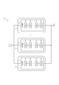
- FIG. 2 is a diagram showing a configuration example in the case where the environmental power generation device 10 has a solar cell.
- the environmental power generation device 10 includes, for example, a solar cell module 11 as a photoelectric conversion module.
- the solar cell module 11 has a thin panel shape, and includes a solar cell group 12 in which a plurality of solar cells 13 are electrically connected in series.
- the solar battery cell 13 is a member constituted by a solar cell which photoelectrically converts incident light such as sunlight and room light and outputs electric power.
- the solar cell modules 11 may be connected to each other via the connecting portion, and may be configured to be foldable, for example, with the connecting portion as a boundary.
- the types of solar cells constituting the solar battery cell 13 can be roughly classified into inorganic solar cells using inorganic materials and organic solar cells using organic materials.
- Si type using silicon (Si) Si
- compound type using a compound, etc. are mentioned.
- organic solar cells low molecular weight vapor deposition systems using organic pigments, polymer coating systems using conductive polymers, coating systems using conversion type semiconductors, thin film systems such as titania, organic dyes, The dye sensitization system etc. which consist of electrolytes are mentioned.
- the solar cells constituting the solar battery cell 13 can also include organic-inorganic hybrid solar cells and solar cells using a perovskite compound.
- a thin panel solar cell 13 is used, and a dye-sensitized solar cell made of a plastic film or the like is preferable.
- the solar battery cell 13 is not limited to what was produced by the said plastic film etc., and, of course, if it is thin similarly, it does not ask
- the solar battery cell group 12 is configured by connecting in series a number of solar battery cells 13 sufficient for the open circuit voltage at both ends to be 5.3 V or more in a normal use mode.
- the normal use mode refers to a mode in which the solar cell group 12 does not generate partial shadows and is used outdoors in the daytime when the weather is not extremely bad.
- the solar cell module 11 may have a plurality of solar cell groups 12.
- the solar cell module 11 has a plurality of solar cell groups 12
- the plurality of solar cell groups 12 are electrically connected in parallel to one another.
- the environmental power generation device 10 has the several solar cell module 11, the photovoltaic cell group 12 contained in each solar cell module 11 is mutually electrically connected in parallel.
- the current control unit 20 is connected to the energy harvesting device 10, controls the current input from the energy harvesting device 10 to increase or decrease, and outputs the current to the external interface 30.
- the current control unit 20 is configured of, for example, a transistor or an FET.
- the external interface 30 is connected to the current control unit 20 and can connect the electronic device 100.
- the external interface 30 outputs the power input from the current control unit 20 to the electronic device 100. That is, the power generated by the environmental power generation device 10 is supplied to the electronic device 100 via the external interface 30.
- a portable battery such as a lead-acid battery, a chargeable / dischargeable secondary battery such as a lithium ion battery, or a smartphone, a notebook PC, or a tablet PC provided with the above secondary battery.
- Equipment can be mentioned.
- the external interface 30 is detachably connected to the electronic device 100 to supply power to the electronic device 100 in response to a power supply request from the electronic device 100, for example.
- the external interface 30 preferably conforms to a predetermined power supply standard, for example, conforms to the USB standard.
- the external interface 30 has a first switch 31.
- the first switch 31 is located on a lead between the current control unit 20 and the electronic device 100, and is a switch that can switch on / off of conduction.
- the first switch 31 can switch between a state in which the electronic device 100 is electrically connected and a state in which the electronic device 100 is electrically disconnected in a state in which the electronic device 100 is physically connected.
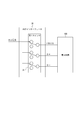
- FIG. 3 is a diagram showing an example of the configuration when the external interface 30 conforms to the USB standard.
- the external interface 30 conforming to the USB standard can be connected to the VBUS terminal, the D + terminal, and the D- terminal defined by the USB standard of the electronic device 100.
- the first switch 31 includes switches respectively corresponding to the VBUS terminal, the D + terminal, and the D ⁇ terminal of the electronic device 100.
- the power generated by the environmental power generation device 10 is input to the switch corresponding to the VBUS terminal.
- the switch corresponding to at least the VBUS terminal among the first switches 31 the state in which power can be supplied to the electronic device 100 and the state in which power can not be supplied can be switched.
- the first current detection unit 40 detects an output current (hereinafter, appropriately abbreviated as “output current”) output from the external interface 30.
- output current an output current
- the first current detection unit 40 detects the current output from the current control unit 20 to the external interface 30, but the detected current is the output current from the external interface 30. equal.
- the first current detection unit 40 has, for example, a predetermined load between the current control unit 20 and the external interface 30, and detects an output current by measuring the potential difference between both ends of the load.
- the comparator 41 compares the output current detected by the first current detection unit 40 with the first threshold, which is the value of the predetermined current, and uses information on the magnitude relationship of the output current to the first threshold as the comparison result. It is output to the switching control unit 80.
- the voltage detection unit 50 detects an input voltage of power input from the environmental power generation device 10 to the power control device 2 (hereinafter, appropriately abbreviated as “input voltage”).
- the comparator 51 compares the input voltage detected by the voltage detection unit 50 with the second threshold which is the value of the predetermined voltage, and uses the information on the magnitude relation of the input voltage to the second threshold as the comparison result as the switching control unit Output to 80.
- the second switch 60 is a switch that is located on a lead from between the energy harvesting device 10 and the current control unit 20 to the ground GND, and can switch the presence or absence of conduction.
- the first switch 31 and the second switch 60 collectively constitute a current switching unit.
- the current switching unit is capable of supplying power generated by the energy harvesting device 10 to the electronic device 100 through the external interface 30, and can not supply the power to the electronic device 100. It is possible to switch between the power supply impossible state.
- the second current detection unit 70 detects the current between the second switch 60 and the ground GND.
- the second current detection unit 70 detects an input current (hereinafter abbreviated as “input current” as appropriate) input from the environmental power generation device 10 to the power control device 2 in the power supply impossible state.
- the second current detection unit 70 has, for example, a predetermined load between the second switch 60 and the ground GND, and detects an output current by measuring the potential difference between both ends of the load.
- the comparator 71 compares the input current detected by the second current detection unit 70 with the third threshold, which is the value of the predetermined current, and uses the information on the magnitude relation of the input current to the third threshold as the comparison result. It is output to the switching control unit 80.
- the switching control unit 80 switches the first switch 31 and the second switch 60 based on the comparison result input from the comparator 41, the comparator 51, and the comparator 71, and switches between the power feeding enabled state and the power feeding disabled state. Control.
- FIG. 4 is a diagram showing the flow of current when the power generation device 1 is in the power supply enable state.
- the flow of current when the power generation device 1 is in the power supply enable state is indicated by a white arrow.
- the first switch 31 is in an energized state (on), and the second switch 60 is in a non-energized state (off).
- the electric power generated by the environmental power generation device 10 is supplied to the electronic device 100.
- the first current detection unit 40 detects an output current to be output to the external interface 30 in a state where power can be supplied.
- FIG. 5 is a diagram showing the flow of current when the power generation device 1 is in the power supply impossible state.
- the flow of current when the power generation device 1 is in the power supply impossible state is indicated by a white arrow.
- the first switch 31 is in a non-energized state (off), and the second switch 60 is in an energized state (on).
- the current based on the power generated by the environmental power generation device 10 does not flow to the current control unit 20, but flows to the ground GND.
- the second current detection unit 70 detects an input current input to the power control device 2 in the power supply impossible state.
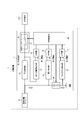
- FIG. 6 is a flowchart showing the operation of the switching control unit 80.
- the switching control unit 80 controls the current switching unit (the first switch 31 and the second switch 60) to set the power feeding enabled state (step S101), and proceeds to the determination process of step S102.
- the power generation device 1 starts power generation by the environmental power generation device 10, maintains a predetermined output voltage, and waits for connection of the electronic device 100.
- the electronic device 100 detects a predetermined output voltage from the power generation device 1 and recognizes that the power can be supplied. For example, the reception of power supply is started by the OTG (On The Go) function.
- the switching control unit 80 determines whether the output current is less than or equal to the first threshold (step S102).
- the first threshold may be, for example, 100 mA.
- the determination processing in step S102 is performed while maintaining the power supply enabled state, that is, the power supply to the electronic device 100 is continued.
- the switching control unit 80 determines that the output current is equal to or less than the first threshold (Yes in step S102)
- the process proceeds to the determination processing in step S103.
- the switching control unit 80 determines whether the input voltage is less than or equal to the second threshold (step S103).
- the second threshold may be, for example, 5.5V.
- the determination processing in step S102 is performed while maintaining the power supply enabled state, that is, the power supply to the electronic device 100 is continued.
- the current control unit is controlled to switch to the power supply impossible state (step S104). Power supply is stopped, and the process proceeds to the determination process of step S105.
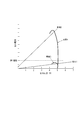
- FIG. 7 is a diagram showing the relationship between the output current and the output voltage based on the generated power of the environmental power generation device 10 under different illumination conditions when the power generation device 1 is in the power supply enable state.
- FIG. 8 is a diagram showing the relationship between the input current and the input voltage based on the generated power of the energy harvesting device 10 under different illumination conditions when a load is directly connected to the energy harvesting device 10. In this example, in the state where the load is directly connected to the environmental power generation device 10, the input current and the input voltage when the power generation device 1 is in the power supply impossible state were measured.
- the illumination intensity of the incident light to the solar cell module 11 of the environmental power generation device 10 is A, and the illumination intensity B is lower than A.
- the environmental power generation device 10 can ensure sufficient generated power for power supply to the electronic device 100.
- the illuminance of incident light is B, the environmental power generation device 10 can not secure sufficient generated power for power supply to the electronic device 100.
- the value when the output voltage is less than the predetermined value may differ depending on the circuit system, and thus the description thereof is omitted.
- the switching control unit 80 determines that a sufficient amount of power generation can be secured. , Power supply to the electronic device 100 is continued.
- the case where the output current has a value equal to or less than the first threshold value will be considered.
- the load current has decreased (changed from load 2 to load 1 in FIG. 8) because the electronic device 100 is close to full charge, and power supply is continued so that the electronic device 100 is fully charged.
- the switching control unit 80 decreases the illuminance of incident light to B. It is determined that power generation sufficient for power supply to the electronic device 100 can not be secured, and power supply to the electronic device 100 is stopped.
- the lower limit voltage shown in FIG. 8 may be a lower limit voltage defined in the standard.
- the lower limit voltage may be 4.75 V (Battery Charging Specification, Rev 1.2 (December 7, 2010) P43 Table 5-1 Voltages "Charging Port Output Voltage” (See BC standard)).
- step S105 the switching control unit 80 determines whether the input current is equal to or less than the third threshold.
- the switching control unit 80 maintains the power supply impossible state, that is, continues stopping the power supply to the electronic device 100. Return.
- the switching control unit 80 proceeds to the determination process of step S106.
- the switching control unit 80 determines whether the state where the input current exceeds the third threshold continues for a predetermined time (step S106). If the state in which the input current exceeds the third threshold does not continue for a predetermined time (No in step S106), the switching control unit 80 proceeds to the determination process in step S105. On the other hand, when the state where the input current exceeds the third threshold continues for a predetermined time (Yes at step S106), the switching control unit 80 controls the current switching unit to switch to the power available state (step S107) Power supply to the device 100 is resumed, and the process proceeds to the determination process of step S108.
- the third threshold is a value equal to or greater than the first threshold.
- the switching control unit 80 can resume supplying power to the electronic device 100 after ensuring that the output current exceeds the first threshold for a predetermined time, so that the electronic device 100 can resume power reception by the OTG function.
- the third threshold may be a value larger than the first threshold.
- the switching control unit 80 resumes the power supply to the electronic device 100 after ensuring that the output current exceeds the first threshold value for a predetermined time more than a predetermined time. be able to.
- the third threshold may be equal to the first threshold. As a result, the switching control unit 80 can restart power feeding more quickly than in the case where the third threshold is a value larger than the first threshold, so that the power can be effectively used.
- the switching control unit 80 determines whether or not the output current is detected (step S108). When the output current is not detected (No in step S108), switching control unit 80 controls the current switching unit to switch to the power supply impossible state (step S109), and after a predetermined time (for example, 1 second) elapses It switches again (step S107) and returns to the determination process of step S108. On the other hand, when the output current is detected (Yes in step S108), the switching control unit 80 returns to the determination process in step S102 while maintaining the power feeding enabled state.
- the process may return to the determination process of step S105.
- the switching control unit 80 may repeat stopping and resuming power supply to the electronic device 100 a predetermined number of times until the output current is detected. Thereby, for example, when the electronic device 100 can not supply power due to physical detachment from the power control device 2 or the like, it is possible to suppress repeating the determination process.
- the power control device 2 when the output current is equal to or less than the first threshold, if the input voltage exceeds the second threshold, the power supply to the electronic device 100 is continued, and the input voltage is the second threshold If it is below, the power supply to the electronic device 100 is stopped. Therefore, even when the output current decreases, the power control device 2 can perform appropriate control in accordance with the situation of the power control device 2 itself or the power supply destination electronic device 100.
- the supply of power to the electronic device 100 is stopped if the input current is equal to or less than the third threshold, and the supply of power to the electronic device 100 is resumed if the input current exceeds the third threshold. Therefore, the power control apparatus 2 resumes the power supply after stopping the power supply to the electronic device 100 and then resuming the power supply after securing a constant current. Can.
- the second current detection unit 70 detects the input current only in the state in which the power can not be supplied. Therefore, since the power control device 2 can directly detect the current of the generated power without being affected by the control of the electronic device 100, the current corresponding to the instantaneous amount of power generation is detected in real time, It is possible to switch to the power available state at an appropriate timing.
- the power control device 2 in the power supply impossible state, the output current is equal to or less than the first threshold and the input voltage is equal to or less than the second threshold, so the power consumption is relatively small.
- the power control apparatus 2 when the output current exceeds the third threshold and the power consumption is relatively large, the power control apparatus 2 is in the power feeding state. Therefore, the power control device 2 can reduce the power consumption that can not be supplied to the electronic device 100 and is wasted.
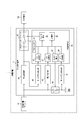
- FIG. 9 is a block diagram showing a schematic configuration of a modification of the power generation device 1.
- the switching control unit 80 may be configured by a microcomputer, and the comparator 41, the comparator 51, and the comparator 71 may not be provided.
- the switching control unit 80 is a microcomputer, the A / D converter 81, the A / D converter 82, the input / output terminal 83, the A / D converter 84, the input / output terminal 85, and the storage unit 86 and a processor 87.
- the A / D converter 81 converts analog information of the output current detected by the first current detection unit 40 into a digital signal, and outputs the digital signal to the processor 87.
- the A / D converter 82 converts analog information of the input voltage detected by the voltage detection unit 50 into a digital signal, and outputs the digital signal to the processor 87.
- the input / output terminal 83 outputs the control signal from the processor 87 to the second switch 60.
- the A / D converter 84 converts analog information of the input current detected by the second current detection unit 70 into a digital signal, and outputs the digital signal to the processor 87.
- the input / output terminal 85 outputs the control signal from the processor 87 to the first switch 31.
- the storage unit 86 includes, for example, a primary storage device or a secondary storage device.
- the storage unit 86 includes, for example, a semiconductor memory or a magnetic memory.
- the semiconductor memory includes, for example, volatile memory or non-volatile memory.
- the magnetic memory includes, for example, a hard disk or a magnetic tape.
- the storage unit 86 stores information such as the first threshold, the second threshold, and the third threshold.
- the processor 87 includes a dedicated processor specialized for a specific process, or a general purpose processor that performs a specific function by reading a specific program.
- the processor 87 compares the input output current, the input voltage, and the digital signal of the input current with the first threshold, the second threshold, and the third threshold stored in the storage unit 86, respectively, to generate a comparison result. . Then, the processor 87 outputs a control signal for switching the first switch 31 and the second switch 60 to the input / output terminal 83 and the input / output terminal 85 based on the comparison result.
- the switching control unit 80 of the modification of the power generation device 1 illustrated in FIG. 9 performs the operation illustrated in the flowchart of FIG. 6.
- the present invention it is possible to provide a power control device and a power generation device capable of performing appropriate control according to the situation of the power control device itself or the electronic device to which power is supplied.
Landscapes
- Engineering & Computer Science (AREA)
- Theoretical Computer Science (AREA)
- Physics & Mathematics (AREA)
- General Engineering & Computer Science (AREA)
- General Physics & Mathematics (AREA)
- Power Engineering (AREA)
- Power Sources (AREA)
- Charge And Discharge Circuits For Batteries Or The Like (AREA)
Abstract
本発明は、電力制御装置自体又は給電先の電子機器の状況に応じた適切な制御を行うことができる、電力制御装置を提供することを目的とする。本発明に係る電力制御装置は、電子機器を接続可能な外部インターフェースを備え、外部環境に応じた電力を発電する環境発電デバイスにより発電された電力を前記外部インターフェースを介して前記電子機器に供給可能である。前記電力制御装置は、前記外部インターフェースからの出力電流を検出する第1の電流検出部と、前記環境発電デバイスからの入力電圧を検出する電圧検出部と、前記出力電流が第1閾値以下である場合、前記入力電圧が第2閾値を超えていれば前記電子機器への給電を継続し、前記入力電圧が前記第2閾値以下であれば前記電子機器への給電を停止する切替制御部と、を備える。
Description
本発明は、電力制御装置及び発電装置に関する。
近年、商用電源を得られない外出先などでも、利用者が、スマートフォン、ノートPC(Personal Computer)、タブレットPCなどの携帯型の電子機器、又はその他の電子機器を利用できるように、外部環境に応じた電力を発電する発電装置の需要が高まっている。このような発電装置としては、例えば太陽光エネルギーを用いて発電する太陽電池を備える装置や、地熱エネルギーを用いて発電する装置等が挙げられる。
このような発電装置によって発電される電力は、外部環境に依存して変化する。従って、発電装置から電子機器に出力される電流は、発電電力に応じて変化しうる。電子機器によっては、給電される電力が低下すると、受電を停止するものがある。このような場合、発電装置によって発電される電力が回復して電子機器に給電される電力が上昇しても電子機器が受電を再開しないことがあった。そして、電子機器に受電を再開させるには、電子機器と発電装置とを繋ぐコネクタを物理的に抜き差しする必要があった。
ところで、デバイス間で通信エラーが発生した場合に、電子スイッチを切り替えることで、コネクタを抜き差しすることなく通信を再開する技術が開発されている(例えば、特許文献1参照。)
外部環境に応じた電力を発電する発電装置では、発電電力が外部環境に依存して変化するため、電子機器が受電を停止しない場合であっても、給電を停止した方が良い場合がある。しかしながら、特許文献1に記載された技術では、このような発電装置に適した制御を行うことができなかった。
そこで、本発明の目的は、上述した課題を解決し、電力制御装置自体又は給電先の電子機器の状況に応じた適切な制御を行うことができる、電力制御装置及び発電装置を提供することにある。
この発明は、上記課題を有利に解決することを目的とするものであり、本発明の電力制御装置は、電子機器を接続可能な外部インターフェースを備え、外部環境に応じた電力を発電する環境発電デバイスにより発電された電力を前記外部インターフェースを介して前記電子機器に供給可能である。前記電力制御装置は、前記外部インターフェースからの出力電流を検出する第1の電流検出部と、前記環境発電デバイスからの入力電圧を検出する電圧検出部と、前記出力電流が第1閾値以下である場合、前記入力電圧が第2閾値を超えていれば前記電子機器への給電を継続し、前記入力電圧が前記第2閾値以下であれば前記電子機器への給電を停止する切替制御部と、を備える。このような構成とすることで、電力制御装置自体又は給電先の電子機器の状況に応じた適切な制御を行うことができる。
ここで、本発明の電力制御装置において、前記電子機器への給電を停止している間の前記環境発電デバイスからの入力電流を検出する第2の電流検出部を更に備え、前記切替制御部は、前記入力電流が第3閾値以下であれば前記電子機器への給電の停止を継続し、前記入力電流が前記第3閾値を超えると前記電子機器への給電を再開することが好ましい。
また、本発明の電力制御装置において、前記切替制御部は、前記電子機器への給電の再開後、前記出力電流が検出されない場合には、前記出力電流が検出されるまで前記電子機器への給電の停止と再開を所定回数繰り返すことが好ましい。
また、本発明の電力制御装置において、前記環境発電デバイスにより発電された電力を前記外部インターフェースを介して前記電子機器に供給可能な給電可能状態と、当該電力を前記電子機器に供給不可能な給電不可状態と、を切り替え可能な電流切替部を更に備え、前記第1の電流検出部は、前記給電可能状態で前記出力電流を検出し、前記第2の電流検出部は、前記給電不可状態で前記入力電流を検出することが好ましい。
また、本発明の電力制御装置において、前記第3閾値は、前記第1閾値以上の値であることが好ましい。
また、本発明の電力制御装置において、前記第3閾値は、前記第1閾値よりも大きい値であることが好ましい。
また、本発明の電力制御装置において、前記切替制御部は、前記入力電流が前記第3閾値を所定時間継続して超えると、前記外部インターフェースへの給電を再開することが好ましい。
また、本発明の電力制御装置において、前記外部インターフェース及び前記電子機器は、USB規格に準拠し、前記切替制御部は、前記電子機器の前記USB規格で規定されたVBUS端子、D+端子、及びD-端子のうち、少なくとも前記VBUS端子を前記外部インターフェースから遮断することで前記外部インターフェースへの給電を停止することが好ましい。
また、本発明の電力制御装置において、前記環境発電デバイスは、入射光を光電変換して発電する太陽電池を含むことが好ましい。
また、この発明は、上記課題を有利に解決することを目的とするものであり、本発明の発電装置は、外部環境に応じた電力を発電する環境発電デバイスと、電子機器を接続可能な外部インターフェースを備え、前記環境発電デバイスにより発電された電力を前記外部インターフェースを介して前記電子機器に供給可能な電力制御装置と、を備える。前記電力制御装置は、前記外部インターフェースからの出力電流を検出する第1の電流検出部と、前記環境発電デバイスからの入力電圧を検出する電圧検出部と、前記出力電流が第1閾値以下である場合、前記入力電圧が第2閾値を超えていれば前記電子機器への給電を継続し、前記入力電圧が前記第2閾値以下であれば前記電子機器への給電を停止する切替制御部と、を備える。このような構成とすることで、発電装置自体又は給電先の電子機器の状況に応じた適切な制御を行うことができる。
本発明によれば、電力制御装置自体又は給電先の電子機器の状況に応じた適切な制御を行うことができる電力制御装置及び発電装置を提供することができる。
以下、本発明の実施の形態について図面を参照して説明する。各図において共通の構成部には、同一の符号を付している。なお、本発明は下記の実施形態に限定されるものではない。
[発電装置1の構成]
図1は、本発明の一実施形態に係る発電装置1の概略構成を示すブロック図である。図1に示すように、発電装置1は、環境発電デバイス10と、電力制御装置2とを備える。電力制御装置2は、電流制御部20と、外部インターフェース30と、第1の電流検出部40と、比較器41と、電圧検出部50と、比較器51と、第2スイッチ60と、第2の電流検出部70と、比較器71と、切替制御部80とを備える。外部インターフェース30は、第1スイッチ31を備える。
図1は、本発明の一実施形態に係る発電装置1の概略構成を示すブロック図である。図1に示すように、発電装置1は、環境発電デバイス10と、電力制御装置2とを備える。電力制御装置2は、電流制御部20と、外部インターフェース30と、第1の電流検出部40と、比較器41と、電圧検出部50と、比較器51と、第2スイッチ60と、第2の電流検出部70と、比較器71と、切替制御部80とを備える。外部インターフェース30は、第1スイッチ31を備える。
環境発電デバイス10は、外部環境に応じた電力を発電する。換言すれば、環境発電デバイス10によって発電される電力は、外部環境に依存して変化する。環境発電デバイス10は、発電した電力を電力制御装置2に出力する。環境発電デバイス10は、例えば、太陽光、室内光などの入射光を光電変換して発電する太陽電池を有する。環境発電デバイス10は、例えば、地熱等のエネルギーを利用して発電する発電モジュールを有する。環境発電デバイス10は、電力制御装置2と連結されていてもよいし、電力制御装置2と着脱可能であってもよい。
図2は、環境発電デバイス10が太陽電池を有する場合の構成例を示す図である。図2に示すように、環境発電デバイス10は、例えば、光電変換モジュールとしての太陽電池モジュール11を有する。ここで、図2には3つの太陽電池モジュール11を示したが、太陽電池モジュール11は1つ又は2つでもよいし、4つ以上でもよい。太陽電池モジュール11は、薄型パネル状であり、複数の太陽電池セル13が電気的に直列に連結した太陽電池セル群12を有する。太陽電池セル13は、太陽光、室内光などの入射光を光電変換して電力を出力する太陽電池で構成された部材である。また、太陽電池モジュール11は、互いに連結部を介して連結し、例えば連結部を境として折り畳むことが可能な構成であってもよい。
太陽電池セル13を構成する太陽電池の種類としては、大別して、無機系材料を用いた無機系太陽電池と、有機系材料を用いた有機系太陽電池とが挙げられる。無機系太陽電池としては、シリコン(Si)を用いたSi系、化合物を用いた化合物系などが挙げられる。また、有機系太陽電池としては、有機顔料を用いた低分子蒸着系、導電性高分子を用いた高分子塗布系、変換型半導体を用いた塗布変換系などの薄膜系、チタニア、有機色素および電解質から成る色素増感系などが挙げられる。また、太陽電池セル13を構成する太陽電池には、有機無機ハイブリッド太陽電池、ペロブスカイト系化合物を用いた太陽電池も含めることができる。本発明においては、薄型パネル状の太陽電池セル13が用いられ、プラスチックフィルム等に作製された色素増感太陽電池が好適である。なお、太陽電池セル13は、上記プラスチックフィルム等に作製されたものに限定されるものでなく、同様の薄型であれば方式を問わないことは言うまでもない。
太陽電池セル群12は、通常の使用態様で両端の開放電圧が5.3V以上となるのに十分な数の太陽電池セル13が直列に連結して構成される。ここで、通常の使用態様とは、太陽電池セル群12に部分影が発生せず、極端な悪天候ではない昼間の屋外で使用される態様をいう。ここで、図2では、太陽電池モジュール11が、1つの太陽電池セル群12を有する例を示したが、太陽電池モジュール11が複数の太陽電池セル群12を有してもよい。太陽電池モジュール11が複数の太陽電池セル群12を有する場合、複数の太陽電池セル群12が互いに電気的に並列に接続される。また、環境発電デバイス10が複数の太陽電池モジュール11を有する場合、各太陽電池モジュール11に含まれる太陽電池セル群12が互いに電気的に並列に接続される。
図1に示すように、電流制御部20は、環境発電デバイス10に接続され、環境発電デバイス10から入力される電流を増減制御して外部インターフェース30に出力する。電流制御部20は、例えばトランジスタ又はFET等によって構成される。
図1に示すように、外部インターフェース30は、電流制御部20に接続され、電子機器100を接続可能である。外部インターフェース30は、電流制御部20から入力される電力を電子機器100に出力する。すなわち、環境発電デバイス10により発電された電力は、外部インターフェース30を介して電子機器100に供給される。外部インターフェース30によって電力が供給される電子機器100としては、鉛蓄電池、リチウムイオン電池等の充放電可能な二次電池、又は、上記二次電池を備えたスマートフォン、ノートPC、タブレットPC等の携帯機器が挙げられる。外部インターフェース30は、電子機器100と着脱可能に接続して、例えば電子機器100からの給電要求を受けて電子機器100に電力を供給する。外部インターフェース30は、所定の給電の規格に準拠していることが好ましく、例えば、USB規格に準拠している。
外部インターフェース30は、第1スイッチ31を有する。第1スイッチ31は、電流制御部20と電子機器100との間の導線上に位置し、導通の有無を切り替え可能なスイッチである。第1スイッチ31は、電子機器100が物理的に接続された状態で、電子機器100を電気的に接続した状態と、電子機器100を電気的に切断した状態とを切り替え可能である。
図3は、外部インターフェース30がUSB規格に準拠する場合の構成例を示す図である。USB規格に準拠する外部インターフェース30は、電子機器100のUSB規格で規定されたVBUS端子、D+端子、及びD-端子と接続可能である。第1スイッチ31は、電子機器100のVBUS端子、D+端子、及びD-端子にそれぞれ対応するスイッチを有する。環境発電デバイス10により発電された電力は、VBUS端子に対応するスイッチに入力される。第1スイッチ31のうち、少なくともVBUS端子に対応するスイッチが切り替えられることで、電子機器100に給電可能な状態と給電不可能な状態とが切り替えられる。換言すれば、電子機器100のUSB規格で規定されたVBUS端子、D+端子、及びD-端子のうち、少なくともVBUS端子が後述する切替制御部80によって外部インターフェース30から遮断されることで、外部インターフェース30への給電が停止する。
第1の電流検出部40は、外部インターフェース30から出力される出力電流(以下、適宜「出力電流」と略記する。)を検出する。なお、図1に示す例では、第1の電流検出部40は、電流制御部20から外部インターフェース30に出力される電流を検出するが、検出される電流は、外部インターフェース30からの出力電流と等しい。第1の電流検出部40は、例えば、電流制御部20と外部インターフェース30との間に所定の負荷を有し、当該負荷の両端の電位差を測定することで、出力電流を検出する。
比較器41は、第1の電流検出部40によって検出される出力電流と、所定の電流の値である第1閾値とを比較し、出力電流の第1閾値に対する大小関係の情報を比較結果として切替制御部80に出力する。
電圧検出部50は、環境発電デバイス10から電力制御装置2に入力される電力の入力電圧(以下、適宜「入力電圧」と略記する。)を検出する。
比較器51は、電圧検出部50によって検出される入力電圧と、所定の電圧の値である第2閾値とを比較し、入力電圧の第2閾値に対する大小関係の情報を比較結果として切替制御部80に出力する。
第2スイッチ60は、環境発電デバイス10と電流制御部20との間からグランドGNDに至る導線上に位置し、導通の有無を切り替え可能なスイッチである。第1スイッチ31及び第2スイッチ60は、合わせて電流切替部を構成する。詳細は後述するが、電流切替部は、環境発電デバイス10により発電された電力を外部インターフェース30を介して電子機器100に供給可能な給電可能状態と、当該電力を電子機器100に供給不可能な給電不可状態と、を切り替え可能である。
第2の電流検出部70は、第2スイッチ60とグランドGNDとの間の電流を検出する。第2の電流検出部70は、給電不可状態では、環境発電デバイス10から電力制御装置2に入力される入力電流(以下、適宜「入力電流」と略記する。)を検出する。第2の電流検出部70は、例えば、第2スイッチ60とグランドGNDとの間に所定の負荷を有し、当該負荷の両端の電位差を測定することで、出力電流を検出する。
比較器71は、第2の電流検出部70によって検出される入力電流と、所定の電流の値である第3閾値とを比較し、入力電流の第3閾値に対する大小関係の情報を比較結果として切替制御部80に出力する。
切替制御部80は、比較器41、比較器51及び比較器71から入力される比較結果に基づいて、第1スイッチ31及び第2スイッチ60を切り替えて、給電可能状態と給電不可状態とを切り替え制御する。
図4は、発電装置1が給電可能状態であるときの電流の流れを示す図である。発電装置1が給電可能状態であるときの電流の流れを、白抜き矢印で示す。図4に示すように、給電可能状態では、第1スイッチ31は通電した状態(オン)であり、第2スイッチ60は通電しない状態(オフ)である。このとき、環境発電デバイス10で発電される電力は電子機器100に給電される。第1の電流検出部40は、給電可能状態では、外部インターフェース30に出力される出力電流を検出する。
図5は、発電装置1が給電不可状態であるときの電流の流れを示す図である。発電装置1が給電不可状態であるときの電流の流れを、白抜き矢印で示す。図5に示すように、給電不可状態では、第1スイッチ31は通電しない状態(オフ)であり、第2スイッチ60は通電した状態(オン)である。このとき、環境発電デバイス10で発電される電力に基づく電流は電流制御部20には流れず、グランドGNDに流れる。第2の電流検出部70は、給電不可状態では、電力制御装置2に入力される入力電流を検出する。
[切替制御部80の動作]
図6は、切替制御部80の動作を示すフローチャートである。
図6は、切替制御部80の動作を示すフローチャートである。
切替制御部80は、電流切替部(第1スイッチ31及び第2スイッチ60)を制御して給電可能状態に設定し(ステップS101)、ステップS102の判定処理に進む。ステップS101の状態において、発電装置1は、環境発電デバイス10による発電を開始し、所定の出力電圧を維持して電子機器100の接続を待機する。この状態で発電装置1の外部インターフェース30に電子機器100が接続される場合、電子機器100は、発電装置1からの所定の出力電圧を検知して電力供給を受けられる状態であると認識し、例えばOTG(On The Go)機能によって電力の供給の受け入れを開始する。
切替制御部80は、出力電流が第1閾値以下であるか否かを判定する(ステップS102)。第1閾値は、例えば100mAであってよい。切替制御部80は、出力電流が第1閾値を超えると判定する場合(ステップS102のNo)、給電可能状態を維持したまま、すなわち電子機器100への給電を継続して、ステップS102の判定処理に戻る。一方、切替制御部80は、出力電流が第1閾値以下であると判定する場合(ステップS102のYes)、ステップS103の判定処理に進む。
切替制御部80は、入力電圧が第2閾値以下であるか否かを判定する(ステップS103)。第2閾値は、例えば5.5Vであってよい。切替制御部80は、入力電圧が第2閾値を超えると判定する場合(ステップS103のNo)、給電可能状態を維持したまま、すなわち電子機器100への給電を継続して、ステップS102の判定処理に戻る。一方、切替制御部80は、入力電圧が第2閾値以下であると判定する場合(ステップS103のYes)、電流切替部を制御して給電不可状態に切り替え(ステップS104)、すなわち電子機器100への給電を停止し、ステップS105の判定処理に進む。
ここで、ステップS102及びS103の判定処理の詳細について、図7及び図8を参照して詳細に説明する。図7は、発電装置1が給電可能状態であるときの、異なる照度条件下での環境発電デバイス10の発電電力に基づく出力電流及び出力電圧の関係を示す図である。図8は、環境発電デバイス10に直接負荷を接続したときの、異なる照度条件下での環境発電デバイス10の発電電力に基づく入力電流及び入力電圧の関係を示す図である。本例では、環境発電デバイス10に直接負荷を接続した状態として、発電装置1が給電不可状態であるときの入力電流及び入力電圧を測定した。ここで、異なる照度条件としては、環境発電デバイス10が有する太陽電池モジュール11への入射光の照度がAのときと、照度がAよりも低いBのときとを示す。入射光の照度がAのとき、環境発電デバイス10は、電子機器100への給電に十分な発電電力を確保できる。一方、入射光の照度がBのとき、環境発電デバイス10は、電子機器100への給電に十分な発電電力を確保できない。なお、図7において、出力電圧が所定値未満であるときの値は、回路系によって異なり得るため、記載を省略する。
図7に示すように、出力電流が第1閾値を超えた値である場合、照度がBよりも大きいAであるため、切替制御部80は十分な発電量が確保できていると判断して、電子機器100への給電を継続する。以下、出力電流が第1閾値以下の値である場合について検討する。出力電流が第1閾値以下であり、かつ、入力電圧が第2閾値を超えている場合、図8に示すように、切替制御部80は、照度がAで十分な発電電力があるにもかかわらず、電子機器100が満充電近傍になったために負荷電流が減少(図8の負荷2から負荷1に変化)したと判断して、電子機器100が満充電となるように給電を継続する。出力電流が第1閾値以下の値であり、かつ、入力電圧が第2閾値以下の値(図8のVB)である場合、切替制御部80は、入射光の照度がBに減少したために電子機器100への給電に十分な発電電力が確保できないと判断して、電子機器100への給電を停止する。
図8に示す下限電圧は、外部インターフェース30が所定の給電の規格に準拠する場合、その規格に定められた下限の電圧であってよい。例えば、外部インターフェース30がUSB給電の規格に準拠する場合、下限電圧は4.75Vであってよい(Battery Charging Specification, Rev 1.2 (December 7,2010) P43 Table 5-1 Voltages 「Charging Port Output Voltage」(BC規格)参照)。
切替制御部80は、ステップS104の処理の後、入力電流が第3閾値以下であるか否かを判定する(ステップS105)。切替制御部80は、入力電流が第3閾値以下である場合(ステップS105のYes)、給電不可状態を維持したまま、すなわち電子機器100への給電の停止を継続し、ステップS105の判定処理に戻る。一方、切替制御部80は、入力電流が第3閾値を超える場合(ステップS105のNo)、ステップS106の判定処理に進む。
切替制御部80は、入力電流が第3閾値を超えた状態が所定時間継続したか否かを判定する(ステップS106)。切替制御部80は、入力電流が第3閾値を超えた状態が所定時間継続しない場合(ステップS106のNo)、ステップS105の判定処理に進む。一方、切替制御部80は、入力電流が第3閾値を超えた状態が所定時間継続した場合(ステップS106のYes)、電流切替部を制御して給電可能状態に切り替え(ステップS107)、すなわち電子機器100への給電を再開し、ステップS108の判定処理に進む。ここで、第3閾値は、第1閾値以上の値である。これにより、切替制御部80は出力電流が第1閾値を所定時間超えることが確保できてから電子機器100への給電を再開するので、電子機器100にOTG機能による受電を再開させることができる。また、第3閾値は、第1閾値よりも大きい値であってもよい。これにより、切替制御部80は出力電流が第1閾値を所定時間より大きく超えることが確保できてから電子機器100への給電を再開するので、電子機器100に対してより安定的な給電をすることができる。また、第3閾値は、第1閾値と等しい値であってもよい。これにより、切り替え制御部80は、第3閾値が第1閾値よりも大きい値である場合よりも迅速に給電を再開することができるので、電力を有効に活用することができる。
切替制御部80は、出力電流が検出されたか否かを判定する(ステップS108)。切替制御部80は、出力電流が検出されない場合(ステップS108のNo)、電流切替部を制御して給電不可状態に切り替え(ステップS109)、所定時間(例えば1秒)経過後、給電可能状態に再度切り替えて(ステップS107)、ステップS108の判定処理に戻る。一方、切替制御部80は、出力電流が検出された場合(ステップS108のYes)、給電可能状態を維持したまま、ステップS102の判定処理に戻る。ここで、ステップS109及びS107の切り替えを所定回数繰り返しても出力電流が検出されない場合、ステップS105の判定処理に戻ってもよい。すなわち、切替制御部80は、出力電流が検出されるまで電子機器100への給電の停止と再開を所定回数繰り返してもよい。これにより、例えば電子機器100が電力制御装置2から物理的に脱離している等によって給電不可能である場合に、判定処理を繰り返すことを抑制することができる。
上記のように、電力制御装置2によると、出力電流が第1閾値以下である場合、入力電圧が第2閾値を超えていれば電子機器100への給電を継続し、入力電圧が第2閾値以下であれば電子機器100への給電を停止する。従って、電力制御装置2は、出力電流が減少した場合であっても、電力制御装置2自体又は給電先の電子機器100の状況に応じた適切な制御を行うことができる。
また、電力制御装置2によると、入力電流が第3閾値以下であれば電子機器100への給電の停止を継続し、入力電流が第3閾値を超えると電子機器100への給電を再開する。よって、電力制御装置2は、電子機器100への給電を停止した後、一定の電流が確保できてから給電を再開するので、電子機器100を物理的に着脱しなくても給電を再開することができる。
また、電力制御装置2によると、第2の電流検出部70は給電不可状態でのみ入力電流を検出する。よって、電力制御装置2は、電子機器100の制御の影響を受けることなく、直接、発電電力の電流を検出することができるので、その瞬間の発電量に応じた電流をリアルタイムで検出して、適切なタイミングで給電可能状態に切り替えることができる。
また、電力制御装置2によると、給電不可状態では、出力電流が第1閾値以下であり、かつ入力電圧が第2閾値以下であるため、消費電力は比較的小さい状態である。一方、電力制御装置2は、出力電流が第3閾値を超えて消費電力が比較的大きい状態では、給電状態となる。従って、電力制御装置2は、電子機器100に給電できずに無駄となる消費電力を低減することができる。
[変形例]
図9は、発電装置1の変形例の概略構成を示すブロック図である。図9に示すように、発電装置1は、切替制御部80をマイクロコンピュータで構成し、比較器41と、比較器51と、比較器71とを備えない構成としてもよい。切替制御部80は、マイクロコンピュータである場合、A/D変換器81と、A/D変換器82と、入出力端子83と、A/D変換器84と、入出力端子85と、記憶部86と、プロセッサ87とを備える。
図9は、発電装置1の変形例の概略構成を示すブロック図である。図9に示すように、発電装置1は、切替制御部80をマイクロコンピュータで構成し、比較器41と、比較器51と、比較器71とを備えない構成としてもよい。切替制御部80は、マイクロコンピュータである場合、A/D変換器81と、A/D変換器82と、入出力端子83と、A/D変換器84と、入出力端子85と、記憶部86と、プロセッサ87とを備える。
A/D変換器81は、第1の電流検出部40によって検出される出力電流のアナログ情報をデジタル信号に変換し、プロセッサ87に出力する。
A/D変換器82は、電圧検出部50によって検出される入力電圧のアナログ情報をデジタル信号に変換し、プロセッサ87に出力する。
入出力端子83は、プロセッサ87からの制御信号を第2スイッチ60に出力する。
A/D変換器84は、第2の電流検出部70によって検出される入力電流のアナログ情報をデジタル信号に変換し、プロセッサ87に出力する。
入出力端子85は、プロセッサ87からの制御信号を第1スイッチ31に出力する。
記憶部86は、例えば一次記憶装置又は二次記憶装置を有する。記憶部86は、例えば半導体メモリ又は磁気メモリ等を有する。半導体メモリは、例えば揮発性メモリ又は不揮発性メモリを含む。磁気メモリは、例えばハードディスク又は磁気テープ等を含む。記憶部86は、第1閾値、第2閾値、及び第3閾値等の情報を記憶する。
プロセッサ87は、特定の処理に特化した専用のプロセッサ、又は特定のプログラムを読み込むことによって特定の機能を実行する汎用のプロセッサを含む。プロセッサ87は、入力された出力電流、入力電圧、及び入力電流のデジタル信号を、記憶部86に記憶された第1閾値、第2閾値、及び第3閾値とそれぞれ比較して比較結果を生成する。そして、プロセッサ87は、比較結果に基づいて、第1スイッチ31及び第2スイッチ60を切り替える制御信号を入出力端子83及び入出力端子85に出力する。
図9に示した発電装置1の変形例の切替制御部80は、図6のフローチャートに示した動作を実行する。
前述したところは本発明の一実施形態を示したにすぎず、特許請求の範囲において、種々の変更を加えてもよいことは言うまでもない。
本発明によれば、電力制御装置自体又は給電先の電子機器の状況に応じた適切な制御を行うことができる、電力制御装置及び発電装置を提供することができる。
1 発電装置
2 電力制御装置
10 環境発電デバイス
11 太陽電池モジュール
12 太陽電池セル群
13 太陽電池セル
20 電流制御部
30 外部インターフェース
31 第1スイッチ
40 第1の電流検出部
41 比較器
50 電圧検出部
51 比較器
60 第2スイッチ
70 第2の電流検出部
71 比較器
80 切替制御部
81 A/D変換器
82 A/D変換器
83 入出力端子
84 A/D変換器
85 入出力端子
86 記憶部
87 プロセッサ
100 電子機器
GND グランド
2 電力制御装置
10 環境発電デバイス
11 太陽電池モジュール
12 太陽電池セル群
13 太陽電池セル
20 電流制御部
30 外部インターフェース
31 第1スイッチ
40 第1の電流検出部
41 比較器
50 電圧検出部
51 比較器
60 第2スイッチ
70 第2の電流検出部
71 比較器
80 切替制御部
81 A/D変換器
82 A/D変換器
83 入出力端子
84 A/D変換器
85 入出力端子
86 記憶部
87 プロセッサ
100 電子機器
GND グランド
Claims (10)
- 電子機器を接続可能な外部インターフェースを備え、外部環境に応じた電力を発電する環境発電デバイスにより発電された電力を前記外部インターフェースを介して前記電子機器に供給可能な電力制御装置であって、
前記外部インターフェースからの出力電流を検出する第1の電流検出部と、
前記環境発電デバイスからの入力電圧を検出する電圧検出部と、
前記出力電流が第1閾値以下である場合、前記入力電圧が第2閾値を超えていれば前記電子機器への給電を継続し、前記入力電圧が前記第2閾値以下であれば前記電子機器への給電を停止する切替制御部と、
を備える電力制御装置。 - 前記電子機器への給電を停止している間の前記環境発電デバイスからの入力電流を検出する第2の電流検出部を更に備え、
前記切替制御部は、前記入力電流が第3閾値以下であれば前記電子機器への給電の停止を継続し、前記入力電流が前記第3閾値を超えると前記電子機器への給電を再開する、
請求項1に記載の電力制御装置。 - 前記切替制御部は、前記電子機器への給電の再開後、前記出力電流が検出されない場合には、前記出力電流が検出されるまで前記電子機器への給電の停止と再開を所定回数繰り返す、請求項2に記載の電力制御装置。
- 前記環境発電デバイスにより発電された電力を前記外部インターフェースを介して前記電子機器に供給可能な給電可能状態と、当該電力を前記電子機器に供給不可能な給電不可状態と、を切り替え可能な電流切替部を更に備え、
前記第1の電流検出部は、前記給電可能状態で前記出力電流を検出し、
前記第2の電流検出部は、前記給電不可状態で前記入力電流を検出する、
請求項2又は3に記載の電力制御装置。 - 前記第3閾値は、前記第1閾値以上の値である、請求項2から4のいずれか一項に記載の電力制御装置。
- 前記第3閾値は、前記第1閾値よりも大きい値である、請求項5に記載の電力制御装置。
- 前記切替制御部は、前記入力電流が前記第3閾値を所定時間継続して超えると、前記外部インターフェースへの給電を再開する、請求項2から6のいずれか一項に記載の電力制御装置。
- 前記外部インターフェース及び前記電子機器は、USB規格に準拠し、
前記切替制御部は、前記電子機器の前記USB規格で規定されたVBUS端子、D+端子、及びD-端子のうち、少なくとも前記VBUS端子を前記外部インターフェースから遮断することで前記外部インターフェースへの給電を停止する、請求項1から7のいずれか一項に記載の電力制御装置。 - 前記環境発電デバイスは、入射光を光電変換して発電する太陽電池を含む、請求項1から8のいずれか一項に記載の電力制御装置。
- 外部環境に応じた電力を発電する環境発電デバイスと、
電子機器を接続可能な外部インターフェースを備え、前記環境発電デバイスにより発電された電力を前記外部インターフェースを介して前記電子機器に供給可能な電力制御装置と、を備える発電装置であって、
前記電力制御装置は、
前記外部インターフェースからの出力電流を検出する第1の電流検出部と、
前記環境発電デバイスからの入力電圧を検出する電圧検出部と、
前記出力電流が第1閾値以下である場合、前記入力電圧が第2閾値を超えていれば前記電子機器への給電を継続し、前記入力電圧が前記第2閾値以下であれば前記電子機器への給電を停止する切替制御部と、を備える、発電装置。
Priority Applications (1)
| Application Number | Priority Date | Filing Date | Title |
|---|---|---|---|
| JP2019525252A JP7115476B2 (ja) | 2017-06-19 | 2018-05-22 | 電力制御装置及び発電装置 |
Applications Claiming Priority (2)
| Application Number | Priority Date | Filing Date | Title |
|---|---|---|---|
| JP2017-119926 | 2017-06-19 | ||
| JP2017119926 | 2017-06-19 |
Publications (1)
| Publication Number | Publication Date |
|---|---|
| WO2018235496A1 true WO2018235496A1 (ja) | 2018-12-27 |
Family
ID=64735705
Family Applications (1)
| Application Number | Title | Priority Date | Filing Date |
|---|---|---|---|
| PCT/JP2018/019678 Ceased WO2018235496A1 (ja) | 2017-06-19 | 2018-05-22 | 電力制御装置及び発電装置 |
Country Status (3)
| Country | Link |
|---|---|
| JP (1) | JP7115476B2 (ja) |
| TW (1) | TW201907313A (ja) |
| WO (1) | WO2018235496A1 (ja) |
Cited By (2)
| Publication number | Priority date | Publication date | Assignee | Title |
|---|---|---|---|---|
| CN110086228A (zh) * | 2019-05-23 | 2019-08-02 | 厦门硅田系统工程有限公司 | 一种太阳能充电电路 |
| JP2022535766A (ja) * | 2019-11-28 | 2022-08-10 | エルジー エナジー ソリューション リミテッド | 電池セル異常劣化診断装置および方法 |
Citations (4)
| Publication number | Priority date | Publication date | Assignee | Title |
|---|---|---|---|---|
| JPS6069720A (ja) * | 1983-09-27 | 1985-04-20 | Toshiba Corp | 太陽光発電システム |
| JPH02156313A (ja) * | 1988-12-08 | 1990-06-15 | Fuji Electric Co Ltd | 太陽光発電システムの始動停止装置 |
| JP2012235631A (ja) * | 2011-05-02 | 2012-11-29 | Seiko Instruments Inc | 二次電池充電装置、二次電池充電システム及び二次電池充電方法 |
| JP2012254004A (ja) * | 2011-05-12 | 2012-12-20 | Sharp Corp | 充電制御装置 |
Family Cites Families (1)
| Publication number | Priority date | Publication date | Assignee | Title |
|---|---|---|---|---|
| JP2015166982A (ja) | 2014-03-04 | 2015-09-24 | キヤノン株式会社 | 画像処理装置及びその制御方法、並びにプログラム |
-
2018
- 2018-05-22 WO PCT/JP2018/019678 patent/WO2018235496A1/ja not_active Ceased
- 2018-05-22 JP JP2019525252A patent/JP7115476B2/ja active Active
- 2018-06-08 TW TW107119876A patent/TW201907313A/zh unknown
Patent Citations (4)
| Publication number | Priority date | Publication date | Assignee | Title |
|---|---|---|---|---|
| JPS6069720A (ja) * | 1983-09-27 | 1985-04-20 | Toshiba Corp | 太陽光発電システム |
| JPH02156313A (ja) * | 1988-12-08 | 1990-06-15 | Fuji Electric Co Ltd | 太陽光発電システムの始動停止装置 |
| JP2012235631A (ja) * | 2011-05-02 | 2012-11-29 | Seiko Instruments Inc | 二次電池充電装置、二次電池充電システム及び二次電池充電方法 |
| JP2012254004A (ja) * | 2011-05-12 | 2012-12-20 | Sharp Corp | 充電制御装置 |
Cited By (4)
| Publication number | Priority date | Publication date | Assignee | Title |
|---|---|---|---|---|
| CN110086228A (zh) * | 2019-05-23 | 2019-08-02 | 厦门硅田系统工程有限公司 | 一种太阳能充电电路 |
| JP2022535766A (ja) * | 2019-11-28 | 2022-08-10 | エルジー エナジー ソリューション リミテッド | 電池セル異常劣化診断装置および方法 |
| US11815558B2 (en) | 2019-11-28 | 2023-11-14 | Lg Energy Solution, Ltd. | Apparatus and method for diagnosing abnormal degradated battery cell |
| JP7403775B2 (ja) | 2019-11-28 | 2023-12-25 | エルジー エナジー ソリューション リミテッド | 電池セル異常劣化診断装置および方法 |
Also Published As
| Publication number | Publication date |
|---|---|
| JPWO2018235496A1 (ja) | 2020-05-21 |
| JP7115476B2 (ja) | 2022-08-09 |
| TW201907313A (zh) | 2019-02-16 |
Similar Documents
| Publication | Publication Date | Title |
|---|---|---|
| US8350411B2 (en) | Modular system for unattended energy generation and storage | |
| JP6233556B1 (ja) | 環境発電装置及び電流制御回路 | |
| US20120176078A1 (en) | Solar chargeable battery for portable devices | |
| US9876371B2 (en) | Battery pack and driving method thereof | |
| US8860252B2 (en) | Power storage system, method of controlling the same, and computer readable recording medium storing a program for executing the method | |
| US8629647B2 (en) | Battery charger apparatus and method for a photovoltaic system | |
| US20170201098A1 (en) | Photovoltaic microstorage microinverter | |
| CN105655528B (zh) | 电池模块及其驱动方法 | |
| CN103477525A (zh) | 具有优先电力供应的受控转换器架构 | |
| WO2022033002A1 (zh) | 一种光伏发电系统 | |
| CA3065294A1 (en) | Energy storage system with string balance function | |
| JP7115476B2 (ja) | 電力制御装置及び発電装置 | |
| US10742165B2 (en) | Bypass mechanisms for energy generation systems | |
| US20110084645A1 (en) | Power supply device and driving method thereof | |
| Zheng et al. | Distributed control for modular plug-and-play subpanel photovoltaic converter system | |
| CN103457519A (zh) | 废热温差发电装置 | |
| Akin | Solar power charger with universal USB output | |
| US8817508B2 (en) | Bidirectional inverter for new renewable energy storage system | |
| US11509164B2 (en) | Systems and methods for solar energy management | |
| Gong et al. | A wide-range charge controller for solar sensor | |
| CN223348628U (zh) | 充电电路和电子设备 | |
| CN104716694B (zh) | 一种基于太阳电池的电源补偿装置和方法 | |
| US20130181692A1 (en) | Power supply system | |
| JPWO2019123880A1 (ja) | 電力配線装置 | |
| CN110061550A (zh) | 一种基于超低电压母线的微纳卫星电源系统 |
Legal Events
| Date | Code | Title | Description |
|---|---|---|---|
| 121 | Ep: the epo has been informed by wipo that ep was designated in this application |
Ref document number: 18819968 Country of ref document: EP Kind code of ref document: A1 |
|
| ENP | Entry into the national phase |
Ref document number: 2019525252 Country of ref document: JP Kind code of ref document: A |
|
| NENP | Non-entry into the national phase |
Ref country code: DE |
|
| 122 | Ep: pct application non-entry in european phase |
Ref document number: 18819968 Country of ref document: EP Kind code of ref document: A1 |