WO2018235439A1 - 電子制御装置 - Google Patents
電子制御装置 Download PDFInfo
- Publication number
- WO2018235439A1 WO2018235439A1 PCT/JP2018/017695 JP2018017695W WO2018235439A1 WO 2018235439 A1 WO2018235439 A1 WO 2018235439A1 JP 2018017695 W JP2018017695 W JP 2018017695W WO 2018235439 A1 WO2018235439 A1 WO 2018235439A1
- Authority
- WO
- WIPO (PCT)
- Prior art keywords
- unique
- ecu
- communication
- electronic control
- local
- Prior art date
- Legal status (The legal status is an assumption and is not a legal conclusion. Google has not performed a legal analysis and makes no representation as to the accuracy of the status listed.)
- Ceased
Links
Images

Classifications
-
- B—PERFORMING OPERATIONS; TRANSPORTING
- B60—VEHICLES IN GENERAL
- B60R—VEHICLES, VEHICLE FITTINGS, OR VEHICLE PARTS, NOT OTHERWISE PROVIDED FOR
- B60R16/00—Electric or fluid circuits specially adapted for vehicles and not otherwise provided for; Arrangement of elements of electric or fluid circuits specially adapted for vehicles and not otherwise provided for
- B60R16/02—Electric or fluid circuits specially adapted for vehicles and not otherwise provided for; Arrangement of elements of electric or fluid circuits specially adapted for vehicles and not otherwise provided for electric constitutive elements
- B60R16/023—Electric or fluid circuits specially adapted for vehicles and not otherwise provided for; Arrangement of elements of electric or fluid circuits specially adapted for vehicles and not otherwise provided for electric constitutive elements for transmission of signals between vehicle parts or subsystems
-
- G—PHYSICS
- G06—COMPUTING OR CALCULATING; COUNTING
- G06F—ELECTRIC DIGITAL DATA PROCESSING
- G06F13/00—Interconnection of, or transfer of information or other signals between, memories, input/output devices or central processing units
- G06F13/14—Handling requests for interconnection or transfer
-
- H—ELECTRICITY
- H04—ELECTRIC COMMUNICATION TECHNIQUE
- H04L—TRANSMISSION OF DIGITAL INFORMATION, e.g. TELEGRAPHIC COMMUNICATION
- H04L12/00—Data switching networks
- H04L12/28—Data switching networks characterised by path configuration, e.g. LAN [Local Area Networks] or WAN [Wide Area Networks]
-
- H—ELECTRICITY
- H04—ELECTRIC COMMUNICATION TECHNIQUE
- H04L—TRANSMISSION OF DIGITAL INFORMATION, e.g. TELEGRAPHIC COMMUNICATION
- H04L12/00—Data switching networks
- H04L12/28—Data switching networks characterised by path configuration, e.g. LAN [Local Area Networks] or WAN [Wide Area Networks]
- H04L12/40—Bus networks
Definitions
- the present invention relates to an electronic control device.
- bus wiring is a connection form in which a plurality of electronic control devices are connected to a common wiring.
- the present connection mode is characterized in that the signal transmitted by the upper ECU is received by all the lower ECUs. In order to distinguish each lower ECU, this is done by specifying an individually assigned ID.
- the bus wiring method has a merit that the weight and cost of the wire harness can be reduced because the number and structure of the wiring are simplified as compared with the conventional direct connection method.
- in-vehicle ECUs also have high reliability requirements. Specifically, if the lower-level ECU connected in the network is broken or the wiring is broken during the idle period of the vehicle, the engine etc. can not be operated properly if it is attempted to start as it is. In some cases, the entire system such as the engine may be damaged. In order to prevent this, it is necessary to have a function to diagnose whether all lower ECUs are properly connected.
- Patent Document 1 is not effective in solving the problems related to the requirement for communication efficiency and activation time.
- An object of the present invention is to provide an electronic control device capable of improving communication efficiency.
- the present invention provides a communication circuit connected to a bus and in communication with at least one lower control apparatus having a unique ID indicating a unique identifier, a memory, and the unique ID from the lower control apparatus.
- An arithmetic circuit having a first operation mode for collecting the unique ID and storing the collected unique ID in the memory and a second operation mode for assigning a local ID indicating an identifier shorter than the unique ID to the lower control apparatus Prepare.
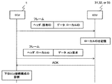
- FIG. 5 is a sequence diagram of an electronic control unit (upper ECU) and a lower ECU according to the embodiment of the present invention.
- FIG. 7 is another sequence diagram of the electronic control unit (upper ECU) and the lower ECU according to the embodiment of the present invention.
- the present embodiment relates to an electronic control unit (hereinafter referred to as “upper-level ECU”) for controlling an engine, a transmission, etc. of an automobile, and a plurality of lower-level electronic control units (hereinafter referred to as “lower-level ECU”) And using bus-like wiring for connection to the lower ECU, and in particular, shortening the communication start-up time with the lower ECU and improving the communication efficiency, and reliability.
- the present invention relates to a host ECU provided with means for securing the flexibility.
- the electronic control unit according to the present embodiment is described as the host ECU 1 in the figure, and the entire system includes the bus wiring 2, a plurality of lower ECUs 31 to 33, a plurality of actuators 41 to 43, etc. It consists of objects 51-53.
- the host ECU 1 is connected to the bus line 2, and the inside thereof includes an arithmetic circuit 11, a communication circuit 12, and a non-volatile memory (hereinafter referred to as an EPROM) 13.
- the EPROM 13 also stores configuration information 14 of the lower ECUs connected.
- the configuration information is information obtained by aggregating information such as a unique ID and a local ID (described later) for each lower ECU.
- the EPROM 13 is specifically implemented by an EEPROM (Electrically Erasable and Programmable Read-Only Memory), it is preferable to use another form such as a battery backup RAM or a ferroelectric memory. It may be a non-volatile memory.
- EEPROM Electrically Erasable and Programmable Read-Only Memory
- the bus wiring 2 has a bus-like wiring configuration, and the lower ECUs 31 to 33 in addition to the upper ECU 1 are logically equally connected.
- the lower ECUs 31 to 33 are connected to the bus wiring 2 and internally include an arithmetic circuit 301, a communication circuit 302, a non-volatile memory (hereinafter referred to as ROM) 303, and a volatile memory (hereinafter referred to as RAM) 305 Be done.
- the lower ECUs 31 to 33 can receive a command from the arithmetic circuit 11 of the upper ECU 1 by a communication method not shown, and can output control to actuators 41 to 43 described later through the arithmetic circuit 301.
- the ROM 303 stores its own unique ID 304, and the RAM 305 stores its own local ID 306. These ID information will be described later.
- the unique ID 304 does not need to be rewritten after the lower-level ECU is produced, it is preferable that the ROM 303 storing the same be implemented as a one-time PROM with a fuse circuit or the like in terms of cost and reliability. However, it may be a non-volatile memory in another form such as an EEPROM.
- the actuators 41 to 43 are, for example, injectors for fuel injection and solenoid valves for hydraulic pressure control, and perform control operations on control targets 51 to 53 described later according to the control output from the arithmetic circuit 301.
- the control objects 51 to 53 are schematically shown separately, they may be integrated.
- the actuators etc. 41 to 43 are respectively an injector, an ignition device, and a temperature sensor (such as a temperature sensor of cooling water)
- the control targets 51 to 53 can be an engine (internal combustion engine) and can be integrally shown.
- the control objects 51 to 53 are, for example, an engine and a transmission, and are driven by control operations of actuators 41 to 43 to realize functions such as power supply and gear change.
- the present invention can be applied to a number other than three.
- the host ECU 1 electronic control unit of the present embodiment includes at least the arithmetic circuit 11, the communication circuit 12, and the EPROM 13 (memory).
- the communication circuit 12 is connected to the bus wiring 2 (bus) and communicates with at least one lower ECU 31 to 33 (lower controller) having a unique ID indicating a unique identifier.
- Arithmetic circuit 11 collects the unique ID from lower ECUs 31 to 33, and stores the collected unique ID in EPROM 13 and assigns a local ID indicating an identifier shorter than the unique ID to lower ECUs 31 to 33 as a second operation mode. It has an operation mode.
- the host ECU 1 can communicate with the lower ECUs 31 to 33 using a local ID shorter than the unique ID. As a result, communication efficiency is improved.
- the unique ID 304 is an ID uniquely assigned at the time of manufacture of the lower ECU, and a number centrally managed so as not to be duplicated in all lower ECUs is allocated. By performing communication with this unique ID 304 as the destination, ID duplication will occur even if the lower ECU is incorporated into the network in any combination at the assembly stage of the entire ECU network (upper ECU, bus wiring, and multiple lower ECUs). Can be avoided. Further, by managing the information in connection with type information and manufacturing information as a secondary application, it can be used for product management (traceability) including after shipment.
- this unique ID 304 is represented by a finite number of digits, the number of digits must be set so that the maximum value is larger than the number of lower ECUs that can be produced. For example, if 100 lower-level ECUs are installed in 100 million vehicles a year, it is necessary to prepare 1 trillion unique IDs in 100 years. This requires a 40-bit ID number (2 to the power of 40) when expressed in binary numbers, and it is difficult to issue an ID without gaps in practice, so there is a margin. It is necessary to prepare a number of digits of about 48 bits.
- the upper ECU performs individual communication to all lower ECUs once.
- the difference between using a unique ID and using a local ID is 2 ms. That is, when the local ID is used, the time of 2 ms can be shortened for each communication, and the communication efficiency can be improved.
- the local ID is determined by the upper ECU after all the unique IDs 304 are collected, and assigned to the lower ECU. At this time, the arithmetic circuit 11 of the host ECU 1 records the relationship between the unique ID 304 and the local ID 306 in the EPROM 13 as the lower ECU configuration information 14.
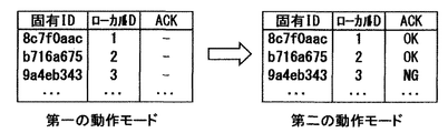
- the lower-level ECU configuration information 14 is storage information that can store information of the unique ID 304, the local ID 306, and an ACK described later for each lower-level ECU 31 to 33, as shown in FIG.
- the host ECU 1 collects the unique IDs 304 of the lower ECUs 31 to 33 and collects the unique ID 304 in the unique ID column of the lower ECU configuration information 14 and the local ID column, and a local ID which is a unique 8-bit number. Are respectively stored (FIG. 3 left). The method of determining the local ID will be described later.
- This operation mode is performed immediately after assembling the ECU network.
- the upper level ECU 1 communicates with the lower level ECUs 31 to 33 by broadcast communication to request the unique ID 304, and the lower level ECUs 31 to 33 return their own unique ID 304 in response thereto.
- the reason for using broadcast here is that the unique ID is unknown at this stage and one-to-one communication is impossible.
- a circuit scale which requires a type using a linear feedback shift register can be small, which is preferable.
- the arithmetic circuit 301 of the lower ECU 31 inputs its own unique ID 304 stored in the ROM 303 into the linear feedback shift register (not shown).
- the linear feedback shift register generates and outputs a random number using the input unique ID 304 as a seed. For example, when the random number is equal to or more than a predetermined threshold value, the arithmetic circuit 301 of the lower ECU 31 notifies the upper ECU 1 of its own unique ID 304 using the communication circuit 302.
- this procedure requires repeating the request for the unique ID several hundreds times even if the number of unique IDs is about 10, which takes a long time.
- this operation mode is an assembly stage of the product, and a relatively long processing time can be allowed as compared with the key ON described later.
- the arithmetic circuit 11 of the host ECU 1 (electronic control unit) simultaneously transmits a unique ID acquisition request to all the lower ECUs 31 to 33 (lower controller) via the communication circuit 12.
- Each lower-level ECU 31 to 33 (lower-level control device) responds to the communication circuit 302 connected to the bus wiring 2 (bus), the ROM 303 (memory) storing the unique ID, and the unique ID acquisition request.
- the corresponding local ID 306 is determined.
- the method of allocation may be completely random, but it is desirable to allocate the local ID 306 in accordance with the function (for example, in which cylinder) the lower-level ECUs 31-33 are in charge of the actuators 41-43.
- the arithmetic circuit 11 of the host ECU 1 determines the local ID according to the functions of the actuators 41 to 43 controlled by the respective lower ECUs 31 to 33 (lower controller).
- the detection of the order in which the lower ECUs 31 to 33 are connected to the bus wiring 2 is performed.
- a current for detection is caused to flow to a specific lower-level ECU, and the connection order is detected using a ratio in which the current for detection is divided by the wiring resistance of the bus wiring 2 can do.
- the arithmetic circuit 11 of the host ECU 1 transmits a command to apply the current I 0 to the bus wiring 2 to each of the plurality of lower ECUs 31 to 33.
- the current detection resistors 141 and 142, the amplifiers 131 and 132, and the arithmetic circuit 11 constitute a current sensor CS.
- the current sensor CS measures the current Is1 flowing through the port 111 and the current Is2 flowing through the port 112 when the plurality of lower ECUs 31 to 33 apply the current I0 to the bus line 2, respectively.
- the load resistor 311, the switch 312 such as a transistor, and the arithmetic circuit 301 constitute a current application device CA.
- the load resistor 311 and the switch 312 are connected in series between the wire 21 and the wire 22.
- the arithmetic circuit 301 turns on the switch 312 when it receives a command to apply a current to the bus wiring 2 from the host ECU 1.
- the arithmetic circuit 11 of the host ECU 1 identifies the order on the bus wiring 2 of the plurality of lower ECUs 31 to 33 based on the current Is1 and the current Is2 measured for each of the plurality of lower ECUs 31 to 33.
- the wiring resistance 23 is schematically represented.
- the arithmetic circuit 11 of the host ECU 1 identifies the order on the bus wiring 2 of the plurality of lower ECUs 31 to 33 based on the difference between the current Is1 and the current Is2 measured for each of the plurality of lower ECUs 31 to 33. Do. In detail, the arithmetic circuit 11 of the host ECU 1 arranges the differences (Is1-Is2) of the current values measured for the respective lower ECUs 31 to 33 in the descending order of the current values on the bus wiring 2 of the lower ECUs 31 to 33. Identify the order.
- the arithmetic circuit 11 of the host ECU 1 generates a plurality of low-order signals based on the ratio of the difference between the currents Is1 and Is2 measured for each of the low-order ECUs 31 to 33 and the sum of the currents Is1 and Is2.
- the order on the bus lines 2 of the ECUs 31 to 33 may be identified.
- the arithmetic circuit 11 of the host ECU 1 can identify the order on the bus wiring 2 of the lower ECUs 31 to 33.
- the arithmetic circuit 11 of the host ECU 1 determines the function of the actuator from the order on the bus wiring 2 of the lower ECUs 31 to 33.
- the host ECU 1 sequentially includes, from the port 111, an injector of # 1 cylinder disposed in the engine to an injector of # 4 cylinder disposed in the engine, and a # 1 solenoid valve to #n solenoid valve disposed in the transmission.
- Design information indicating that various # 1 sensors to #n sensors are connected to the bus line 2 is stored in the EPROM 13.
- the arithmetic circuit 11 of the upper ECU 1 can determine the functions of actuators 41 to 43 that the lower ECUs 31 to 33 are in charge of from the identified lower ECUs 31 to 33 in order by referring to the design information.
- the arithmetic circuit 11 of the host ECU 1 uses, for example, an ID assigned to each function as design information as a local ID. Note that the arithmetic circuit 11 of the host ECU 1 may calculate the local ID by performing a predetermined operation in order on the bus wiring 2 of the identified lower ECUs 31 to 33.
- the arithmetic circuit 11 of the host ECU 1 identifies the connection order of the lower ECUs 31 to 33 (lower controller) in the bus wiring 2 (bus), and the local ECUs 31 to 33 localize according to the identified connection order. Determine the ID.
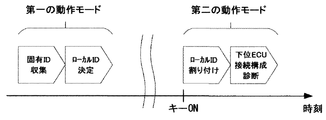
- the second operation mode is started by a key-on operation instructing the start of the vehicle as shown in FIG.
- the upper ECU 1 performs communication to assign the local IDs individually to the lower ECUs 31 to 33 based on the unique ID field and the local ID field of the lower ECU configuration information 14.
- the lower ECUs 31 to 33 return an acknowledgment (hereinafter, referred to as an ACK) to the communication.
- the host ECU 1 registers in the ACK column of the lower ECU configuration information 14 whether or not this ACK has been returned for each communication (FIG. 3 right).
- This operation mode is implemented each time the key is turned on.
- the corresponding local ID (“1” in FIG. 3) is assigned to the unique ID (“8c7f0aac” in FIG. 3) of the lower ECU 31 from the upper ECU 1.
- the lower ECU 31 stores the received value of the local ID in its own RAM 306, and sends back an ACK signal to the upper ECU 1.
- the upper ECU 1 receives the ACK, the upper ECU 1 records information indicating “OK” in the ACK column of the lower ECU configuration information 14, and records information indicating “NG” if the information can not be received.
- the host ECU 1 repeats the above process as many as the number of the lower ECUs described in the configuration information 14.
- a disconnection symbol 6 in FIG. 1
- the lower ECU 33 can not receive the communication of the local ID assignment, and returns an ACK signal. I can not do it either.
- information indicating "NG" is recorded in the ACK column of the lower ECU configuration information 14.
- the connection configuration of the lower ECUs 31 to 33 is abnormal, that is, the failure of the lower ECUs 31 to 33 or the disconnection (6 in FIG. 1) Can be diagnosed.
- the ACK column of the lower ECU 33 is “NG”, it can be determined that an abnormality occurs in the connection with the lower ECU 33.
- the arithmetic circuit 11 of the host ECU 1 transmits the local ID to the lower ECUs 31 to 33 (lower controller) via the communication circuit 12 in the second operation mode, and the lower ECUs 31 to 31 via the communication circuit 12
- an ACK acknowledgement response
- the communication circuit 12 is diagnosed as abnormal.
- connection configuration Even if the connection configuration is normal, there is a possibility that the ACK can not be received due to noise or the like, so when communication can not be received, it is possible to distinguish single-shot noise and abnormality of the connection configuration by trying communication multiple times. .
- connection configuration If an abnormality in the connection configuration is detected, communication with the lower-level ECU can not be performed, and there is a high possibility that the vehicle can not be operated safely. Take measures such as For example, when the upper ECU can not receive ACK from at least one lower ECU, it determines that it is abnormal, for example, turns on a warning light. By thus diagnosing the ECU connection configuration, it is possible to improve the reliability required for the on-vehicle device.
- each lower level ECU controls an actuator.
- the arithmetic circuit 11 of the host ECU 1 determines that the communication between the lower ECUs 31 to 33 (lower controller) and the communication circuit 12 is all normal. Start sending and receiving data used to control the This can improve the reliability of communication.
- the host ECU 1 since the host ECU 1 communicates with the lower ECUs 31 to 33 using a local ID shorter than the unique ID, the communication data amount is reduced, and the communication time is shortened. As a result, system startup time is shortened.
- the present invention is not limited to the above-described embodiment, but includes various modifications.
- the embodiments described above are described in detail in order to explain the present invention in an easy-to-understand manner, and are not necessarily limited to those having all the described configurations.
- each of the configurations, functions, and the like described above may be realized by hardware by designing part or all of them, for example, by an integrated circuit.
- each configuration, function, and the like described above may be realized by software by a processor (arithmetic circuit) interpreting and executing a program that realizes each function.
- Information such as a program, a table, and a file for realizing each function can be placed in a memory, a hard disk, a recording device such as an SSD (Solid State Drive), or a recording medium such as an IC card, an SD card, or a DVD.
- the embodiment of the present invention may have the following aspects.
- a plurality of lower control devices having unique IDs are connected by bus-like wiring, have at least two operation modes, and collect unique IDs of lower control devices in the first operation mode and store them In the second control mode, a local ID shorter than the unique ID is allocated to the lower control device having the unique ID stored in the second operation mode.
- the local ID is determined according to the connection order of the bus-like wirings of the lower control units.
- the improvement of the communication efficiency and the shortening of the start-up time can be realized, and an electronic control device suitable for in-vehicle use can be provided.
Landscapes
- Engineering & Computer Science (AREA)
- Computer Networks & Wireless Communication (AREA)
- Signal Processing (AREA)
- Theoretical Computer Science (AREA)
- Mechanical Engineering (AREA)
- Small-Scale Networks (AREA)
- Physics & Mathematics (AREA)
- General Engineering & Computer Science (AREA)
- General Physics & Mathematics (AREA)
Abstract
通信効率を向上することができる電子制御装置を提供する。 上位ECU1(電子制御装置)は、少なくとも演算回路11、通信回路12、EPROM13(メモリ)を備える。通信回路12は、バス配線2(バス)に接続され、固有の識別子を示す固有IDを有する少なくとも1つの下位ECU31~33(下位制御装置)と通信する。演算回路11は、下位ECU31~33から固有IDを収集し、収集した固有IDをEPROM13に記憶する第1の動作モード及び固有IDより短い識別子を示すローカルIDを下位ECU31~33に割り付ける第2の動作モードを有する。
Description
本発明は、電子制御装置に関する。
[省配線化への要求]
近年の自動車の高機能化は著しく、それに伴って車両に搭載されるアクチュエータやセンサの数が増加している。それに伴い、上位ECU(Electronic Control Unit:電子制御装置)としての例えばエンジン制御ECUと、アクチュエータ(例えば燃料噴射用のインジェクタ)やセンサとの間を接続するワイヤハーネスの重量およびコストも増大している。これに対し、燃費改善等のための軽量化要求から、ワイヤハーネスを省配線化したいという要求が強まっている。以下、アクチュエータやセンサをアクチュエータ等と略して記述する。
近年の自動車の高機能化は著しく、それに伴って車両に搭載されるアクチュエータやセンサの数が増加している。それに伴い、上位ECU(Electronic Control Unit:電子制御装置)としての例えばエンジン制御ECUと、アクチュエータ(例えば燃料噴射用のインジェクタ)やセンサとの間を接続するワイヤハーネスの重量およびコストも増大している。これに対し、燃費改善等のための軽量化要求から、ワイヤハーネスを省配線化したいという要求が強まっている。以下、アクチュエータやセンサをアクチュエータ等と略して記述する。
上位ECUとアクチュエータ等との接続に用いられるワイヤハーネスの省配線化手法としては、従来は上位ECUとアクチュエータ等との間とを個別の配線で直結していたものを共通のバス配線で置き換え、さらに各アクチュエータ等に通信機能および制御機能を備える下位ECUを追加し、上位ECUから通信を介して伝達される指示をもとに下位ECUが制御動作を行う形式が有効である。
[バス配線と衝突回避の必要性]
上述の「バス配線」は、共通の配線に対して複数の電子制御装置を接続する接続形態である。本接続形態では、上位ECUが送信した信号は全ての下位ECUで受信されるという特徴がある。各下位ECUを区別するには、個別に割り当てられたIDを指定することでこれを行う。バス配線方式は、従来の直結方式と比べて配線の本数および構造が単純となるため、ワイヤハーネスの重量およびコストを軽減できるメリットがある。
上述の「バス配線」は、共通の配線に対して複数の電子制御装置を接続する接続形態である。本接続形態では、上位ECUが送信した信号は全ての下位ECUで受信されるという特徴がある。各下位ECUを区別するには、個別に割り当てられたIDを指定することでこれを行う。バス配線方式は、従来の直結方式と比べて配線の本数および構造が単純となるため、ワイヤハーネスの重量およびコストを軽減できるメリットがある。
一方で、バス配線方式にはデメリットも存在する。同一のバス配線の中でIDが重複してしまうと複数の下位ECUが同時に返信して信号が衝突しまい、通信が成立しないことがある点である。
[固有ID]
これを回避するには、同一のバス配線の中でのIDが重複しないように手段を講じる必要がある。これは、生産するすべての下位ECUに重複しない固有のID(以下、固有IDと記す)を割り付けることで実現できる。ただしこの固有IDは、その取り得る最大値を生産し得る下位ECUの数よりも多く確保する必要があるため、その桁数(固有IDを二進数で表す場合、bit数)を大きくする必要がある。一方で、このIDは通信のたびに宛先として送信する必要があるため、桁数が多いとそのぶん通信効率の低下につながってしまう。
これを回避するには、同一のバス配線の中でのIDが重複しないように手段を講じる必要がある。これは、生産するすべての下位ECUに重複しない固有のID(以下、固有IDと記す)を割り付けることで実現できる。ただしこの固有IDは、その取り得る最大値を生産し得る下位ECUの数よりも多く確保する必要があるため、その桁数(固有IDを二進数で表す場合、bit数)を大きくする必要がある。一方で、このIDは通信のたびに宛先として送信する必要があるため、桁数が多いとそのぶん通信効率の低下につながってしまう。
[起動時間への要求]
次に、自動車用制御装置(以下、車載ECUと記す)における起動時間への要求について述べる。車載ECUでは、キーON(例えば、スタートスイッチON又はイグニッションスイッチON)時、すなわちユーザーが車両を起動する操作をしてからエンジン等が実際に起動するまでをある定められた時間以内に完了させる必要がある。このためには、上位ECUと下位ECUとの通信の立ち上げ時間も短くする必要がある。
次に、自動車用制御装置(以下、車載ECUと記す)における起動時間への要求について述べる。車載ECUでは、キーON(例えば、スタートスイッチON又はイグニッションスイッチON)時、すなわちユーザーが車両を起動する操作をしてからエンジン等が実際に起動するまでをある定められた時間以内に完了させる必要がある。このためには、上位ECUと下位ECUとの通信の立ち上げ時間も短くする必要がある。
[信頼性への要求]
一方で、車載ECUでは信頼性に対する要求も高い。具体的には、車両の休止期間中にネットワーク内に接続された下位ECUが故障していたり、配線が断線していた場合、そのまま起動しようとすると正しくエンジン等を動作させることができず、場合によってはエンジン等のシステム全体を故障させてしまうおそれがある。これを防ぐためには、全ての下位ECUが正しく接続されているかを診断する機能が必要となる。
一方で、車載ECUでは信頼性に対する要求も高い。具体的には、車両の休止期間中にネットワーク内に接続された下位ECUが故障していたり、配線が断線していた場合、そのまま起動しようとすると正しくエンジン等を動作させることができず、場合によってはエンジン等のシステム全体を故障させてしまうおそれがある。これを防ぐためには、全ての下位ECUが正しく接続されているかを診断する機能が必要となる。
[従来例]
このような診断方法として、特許文献1に示されているような例が知られている。本特許文献では、上位の監視制御端末が下位の監視対象装置の識別情報を記憶し、対応する監視対象装置を呼び出すことで監視対象装置の接続等が正常であるかを監視する手法が提示されている。この手法を応用することで全ての下位ECUが正しく接続されているかを診断することができ、システム全体の信頼性を向上させることができる。
このような診断方法として、特許文献1に示されているような例が知られている。本特許文献では、上位の監視制御端末が下位の監視対象装置の識別情報を記憶し、対応する監視対象装置を呼び出すことで監視対象装置の接続等が正常であるかを監視する手法が提示されている。この手法を応用することで全ての下位ECUが正しく接続されているかを診断することができ、システム全体の信頼性を向上させることができる。
一方で、特許文献1に示された手法は、通信効率や起動時間への要求に関する課題の解決には効果がない。
本発明の目的は、通信効率を向上することができる電子制御装置を提供することにある。
上記目的を達成するために、本発明は、バスに接続され、固有の識別子を示す固有IDを有する少なくとも1つの下位制御装置と通信する通信回路と、メモリと、前記下位制御装置から前記固有IDを収集し、収集した前記固有IDを前記メモリに記憶する第1の動作モード及び前記固有IDより短い識別子を示すローカルIDを前記下位制御装置に割り付ける第2の動作モードを有する演算回路と、を備える。
本発明によれば、通信効率を向上することができる。上記した以外の課題、構成及び効果は、以下の実施形態の説明により明らかにされる。
以下、図面を用いて、本発明の実施形態による電子制御装置の構成及び動作について説明する。各図において、同一符号は同一部分を示す。なお、本実施形態は自動車のエンジンや変速機等の制御を行うための電子制御装置(以下、「上位ECU」と記す)に関し、その配下に複数の下位の電子制御装置(以下、「下位ECU」と記す)を有し、前記下位ECUとの接続にバス状の配線を利用しているものであって、特に、前記下位ECUとの通信立ち上げ時間の短縮と通信効率の向上、および信頼性の確保を図るための手段を備えた上位ECUに関する。
[全体構成]
以下、本発明に係る実施形態による電子制御装置等の接続構成と動作について、図1、図2、および図3を用いて説明する。本実施形態による電子制御装置は図中で上位ECU1として記載しており、全体のシステムとしては上位ECU1の他にバス配線2、複数の下位ECU31~33、複数のアクチュエータ等41~43、および制御対象51~53から構成される。
以下、本発明に係る実施形態による電子制御装置等の接続構成と動作について、図1、図2、および図3を用いて説明する。本実施形態による電子制御装置は図中で上位ECU1として記載しており、全体のシステムとしては上位ECU1の他にバス配線2、複数の下位ECU31~33、複数のアクチュエータ等41~43、および制御対象51~53から構成される。
上位ECU1は、バス配線2と接続され、その内部は演算回路11、通信回路12、および不揮発性メモリ(以下、EPROMと記す)13から構成される。また、EPROM13には接続される下位ECUの構成情報14が格納されている。この構成情報は、各下位ECUについての固有IDやローカルID等(後述)の情報を集約したものである。
なお、EPROM13は具体的にはEEPROM(Electrically Erasable and Programmable Read-Only Memory)で実装されることがコスト面において好適であるが、バッテリバックアップ型のRAMや強誘電体メモリなど、他の形式での不揮発性メモリであってもよい。
バス配線2はバス状の配線形態となっており、上位ECU1のほか、下位ECU31~33が論理的に平等に接続されている。
下位ECU31~33は、バス配線2と接続され、その内部は演算回路301、通信回路302、不揮発性メモリ(以下、ROMと記す)303、および揮発性メモリ(以下、RAMと記す)305から構成される。下位ECU31~33は図示しない通信手法により、上位ECU1の演算回路11からの指令を受け、演算回路301を通じて後述するアクチュエータ等41~43へ制御出力を行うことができる。
また、ROM303には自らの固有ID304、RAM305には自らのローカルID306が格納されている。これらのID情報については後述する。なお、固有ID304は下位ECUが生産されたのちに書き換える必要が無いため、それを格納するROM303はヒューズ回路等でのワンタイムPROMで実装されることがコスト面および信頼性の面で好適であるが、EEPROM等の他の形式での不揮発性メモリであってもよい。
アクチュエータ等41~43は、例えば燃料噴射用のインジェクタや油圧制御用のソレノイドバルブであり、演算回路301からの制御出力に応じ、後述の制御対象51~53のそれぞれに対して制御動作を行う。なお、図1の例では、制御対象51~53を別体として模式的に表しているが、一体であってもよい。例えば、アクチュエータ等41~43がそれぞれインジェクタ、点火装置、温度センサ(冷却水の温度センサ等)である場合、制御対象51~53は、エンジン(内燃機関)となり一体として表すことができる。
制御対象51~53は、例えばエンジンや変速機であり、アクチュエータ等41~43の制御動作により駆動され、動力の供給や変速などの機能を実現する。
なお、本実施例では下位ECU31~33およびアクチュエータ等41~43を3個ずつとした例で説明しているが、この個数は3以外の数でも同様に本発明を適用することができる。
このように、本実施形態の上位ECU1(電子制御装置)は、少なくとも演算回路11、通信回路12、EPROM13(メモリ)を備える。通信回路12は、バス配線2(バス)に接続され、固有の識別子を示す固有IDを有する少なくとも1つの下位ECU31~33(下位制御装置)と通信する。演算回路11は、下位ECU31~33から固有IDを収集し、収集した固有IDをEPROM13に記憶する第1の動作モード及び固有IDより短い識別子を示すローカルIDを下位ECU31~33に割り付ける第2の動作モードを有する。
これにより、上位ECU1は、固有IDよりも短いローカルIDを用いて、下位ECU31~33と通信を行うことができる。その結果、通信効率が向上する。
[固有ID]
次に、固有ID304について説明する。固有ID304は、下位ECUの製造時に一意に割りつけられたIDであり、すべての下位ECUにおいて重複しないよう一元的に管理された番号が割り当てられている。この固有ID304を宛先として通信を行うことで、ECUネットワーク全体(上位ECU、バス配線、および複数の下位ECU)の組立段階で下位ECUがどのような組み合わせでネットワークに組込まれたとしてもIDの重複を回避することができる。また、副次的な用途として、型式情報や製造情報と紐づけて管理しておくことで、出荷後を含めた製品管理(トレーサビリティ)に役立てることができる。
次に、固有ID304について説明する。固有ID304は、下位ECUの製造時に一意に割りつけられたIDであり、すべての下位ECUにおいて重複しないよう一元的に管理された番号が割り当てられている。この固有ID304を宛先として通信を行うことで、ECUネットワーク全体(上位ECU、バス配線、および複数の下位ECU)の組立段階で下位ECUがどのような組み合わせでネットワークに組込まれたとしてもIDの重複を回避することができる。また、副次的な用途として、型式情報や製造情報と紐づけて管理しておくことで、出荷後を含めた製品管理(トレーサビリティ)に役立てることができる。
この固有ID304は有限の桁数で表わされるが、その桁数はその最大値が生産し得る下位ECUの数よりも多くなるよう設定する必要がある。例えば、年間1億台の自動車に100個の下位ECUが搭載された場合、100年間で一兆個の固有IDを用意する必要がある。これには2進数で表した時に40bitの桁数のID(2の40乗のID)が必要であり、また、実際にはIDを隙間なく発行することは困難であることから、余裕を持たせて48bit程度の桁数を用意することが必要となる。
[ローカルID]
前述の固有IDを用いることで通信を行うことができるが、桁数が多いために通信に時間がかかり、通信効率を高くすることができないという課題がある。本実施例ではECUネットワーク全体に接続された下位ECUの数は3つであるが、実際の応用でも通信容量等の問題から10個程度が上限となることが多い。この場合、ネットワーク内の識別という目的のために必要なID桁数は4bitと短い。このように、固有ID304をそれより短いID(以下、ローカルID306と記す)に置き換えることで通信時間を短縮し、通信効率を向上させることができる。
前述の固有IDを用いることで通信を行うことができるが、桁数が多いために通信に時間がかかり、通信効率を高くすることができないという課題がある。本実施例ではECUネットワーク全体に接続された下位ECUの数は3つであるが、実際の応用でも通信容量等の問題から10個程度が上限となることが多い。この場合、ネットワーク内の識別という目的のために必要なID桁数は4bitと短い。このように、固有ID304をそれより短いID(以下、ローカルID306と記す)に置き換えることで通信時間を短縮し、通信効率を向上させることができる。
例を挙げると、固有IDの長さが48bit、ローカルIDの長さが4bit、下位ECU数が10個、通信速度が200kbpsである場合、上位ECUからすべての下位ECUへ個別通信を1回行うのにかかる時間差について考えると、固有IDを用いる場合とローカルIDを用いる場合とでの差は2msとなる。すなわち、ローカルIDを用いる場合は通信毎に2msの時間を短縮でき、通信効率を向上させることができる。
このローカルIDは固有ID304を全て収集した後に上位ECUにて決定し、下位ECUへ割り当てる。このとき、上位ECU1の演算回路11は、固有ID304とローカルID306との関係を下位ECU構成情報14としてEPROM13に記録する。この下位ECU構成情報14は、図3に示すように各下位ECU31~33について、固有ID304、ローカルID306、および後述するACKの情報を記憶することができる記憶情報である。
[第一の動作モード]
以下、本実施形態での上位ECU1の、通信立ち上げにおける動作について説明する。本実施形態での通信立ち上げは、図2に示すように第一および第二の2つのモードに分けて実施する。
以下、本実施形態での上位ECU1の、通信立ち上げにおける動作について説明する。本実施形態での通信立ち上げは、図2に示すように第一および第二の2つのモードに分けて実施する。
第一の動作モードでは、上位ECU1は下位ECU31~33の固有ID304を収集して下位ECU構成情報14の固有ID欄、およびローカルID欄へ収集した固有ID304、ユニークな8bitの数字であるローカルIDをそれぞれ記憶する(図3左)。なお、ローカルIDの決定方法については、後述する。
本動作モードはECUネットワークを組み立てた直後に行う。具体的な手法としては、上位ECU1から下位ECU31~33へ同報通信にて固有ID304を要求する通信を行い、下位ECU31~33はそれに応答して自らの固有ID304を返信する。ここで同報通信を用いる理由は、この段階では固有IDが不明で、1対1の通信は不可能であるためである。
[乱数利用による衝突抑制]
ここで、下位ECU31~33は同一のバス配線2につながっているため、下位ECU31~33が単純に固有IDの要求に応答するとその通信が衝突してしまい、通信が成立しない。これを回避するには、各下位ECUにおいて自らの固有IDをもとに乱数処理を行い、返信有無を決定する手法が有効である。この乱数値を固有IDの要求ごとに更新することで、上位ECU1が固有IDの要求を多数回繰り返すうちに1つの下位ECUだけが返信するタイミングが訪れ、衝突を回避して固有を収集できる。
ここで、下位ECU31~33は同一のバス配線2につながっているため、下位ECU31~33が単純に固有IDの要求に応答するとその通信が衝突してしまい、通信が成立しない。これを回避するには、各下位ECUにおいて自らの固有IDをもとに乱数処理を行い、返信有無を決定する手法が有効である。この乱数値を固有IDの要求ごとに更新することで、上位ECU1が固有IDの要求を多数回繰り返すうちに1つの下位ECUだけが返信するタイミングが訪れ、衝突を回避して固有を収集できる。
このような乱数処理の手法としては、線形帰還シフトレジスタを用いる形式が必要な回路規模が小さくて済み、好適である。具体的には、下位ECU31の演算回路301は、固有IDの要求を受信した場合、ROM303に記憶される自らの固有ID304を線形帰還シフトレジスタ(不図示)に入力する。線形帰還シフトレジスタは入力された固有ID304をシードとして乱数を生成して出力する。下位ECU31の演算回路301は、例えば、乱数が所定の閾値以上の場合に、自身の固有ID304を、通信回路302を用いて上位ECU1に通知する。
なお、この手続きは全ての固有IDを収集するまでに、固有IDの数が10個程度である場合でも固有IDの要求を数百回繰り返す必要があり長い時間を要する。ただし、本動作モードは製品の組立段階であり、後述するキーON時と比べて比較的長い処理時間を許容することができる。
ここで、上位ECU1(電子制御装置)の演算回路11は、通信回路12を介してすべての下位ECU31~33(下位制御装置)に同時に固有IDの取得要求を送信する。それぞれの下位ECU31~33(下位制御装置)は、バス配線2(バス)に接続される通信回路302と、固有IDを記憶するROM303(メモリ)と、固有IDの取得要求に応答して、固有IDに基づいて算出されるタイミングに通信回路302を介して固有IDを上位ECU1に送信する演算回路301と、を備える。それぞれの下位ECU31~33が固有IDを同時に送信することを抑制することができる。その結果、通信が衝突することを抑制することができる。
[ローカルIDの決定]
こうして収集した各固有ID304に対し、対応するローカルID306を決定する。割り振りの方法は全くのランダムでも良いが、各下位ECU31~33が担当するアクチュエータ等41~43の機能(例えば、何番目の気筒に設置されているか)に応じてローカルID306を割り振ることが望ましい。
こうして収集した各固有ID304に対し、対応するローカルID306を決定する。割り振りの方法は全くのランダムでも良いが、各下位ECU31~33が担当するアクチュエータ等41~43の機能(例えば、何番目の気筒に設置されているか)に応じてローカルID306を割り振ることが望ましい。
すなわち、好ましくは、上位ECU1の演算回路11は、それぞれの下位ECU31~33(下位制御装置)が制御するアクチュエータ等41~43の機能に応じてローカルIDを決定する。
これは、上位ECU1から見てローカルID306と対応する機能が常に同じとなるため、動作の指示において特別な変換手処理を必要としないためである。
各下位ECU31~33が担当するアクチュエータ等41~43の機能を判定するには、バス配線2に下位ECU31~33が接続されている順序を検出することで行う。具体的な手法としては、後述するように、例えば特定の下位ECUに検出用の電流を流させて、その検出用電流がバス配線2の配線抵抗により分流される比を用いて接続順序を検出することができる。
[バスに接続されるECUの順序の同定]
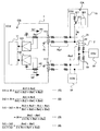
図4に示すように、上位ECU1の演算回路11は、バス配線2に電流I0を印加する指令を複数の下位ECU31~33のそれぞれに送信する。ここで、電流検出抵抗器141、142、アンプ131、132、演算回路11は、電流センサCSを構成する。電流センサCSは、複数の下位ECU31~33のそれぞれがバス配線2に電流I0を印加することによりポート111に流れる電流Is1及びポート112に流れる電流Is2をそれぞれ測定する。
図4に示すように、上位ECU1の演算回路11は、バス配線2に電流I0を印加する指令を複数の下位ECU31~33のそれぞれに送信する。ここで、電流検出抵抗器141、142、アンプ131、132、演算回路11は、電流センサCSを構成する。電流センサCSは、複数の下位ECU31~33のそれぞれがバス配線2に電流I0を印加することによりポート111に流れる電流Is1及びポート112に流れる電流Is2をそれぞれ測定する。
一方、下位ECU31~33において、負荷抵抗311、トランジスタ等のスイッチ312、演算回路301は、電流印加装置CAを構成する。負荷抵抗311及びスイッチ312は、配線21と配線22の間に直列接続される。演算回路301は、バス配線2に電流を印加する指令を上位ECU1から受信した場合、スイッチ312をオンする。
上位ECU1の演算回路11は、複数の下位ECU31~33のそれぞれに対して測定された電流Is1と電流Is2に基づいて、複数の下位ECU31~33のバス配線2上の順序を同定する。なお、図4では、配線抵抗23を模式的に表している。
例えば、上位ECU1の演算回路11は、複数の下位ECU31~33のそれぞれに対して測定された電流Is1と電流Is2の差に基づいて、複数の下位ECU31~33のバス配線2上の順序を同定する。詳細には、上位ECU1の演算回路11は、それぞれの下位ECU31~33に対して測定された電流値の差分(Is1-Is2)を大きい順に並べることにより、下位ECU31~33のバス配線2上の順序を同定する。
なお、上位ECU1の演算回路11は、複数の下位ECU31~33のそれぞれに対して測定された電流Is1と電流Is2の差と、電流Is1と電流Is2の和との比に基づいて、複数の下位ECU31~33のバス配線2上の順序を同定してもよい。
これにより、上位ECU1の演算回路11は、下位ECU31~33のバス配線2上の順序を同定することができる。上位ECU1の演算回路11は、下位ECU31~33のバス配線2上の順序からアクチュエータの機能を判定する。
例えば、上位ECU1は、ポート111から順に、エンジンに配設される#1気筒のインジェクタ~#4気筒のインジェクタ、変速機に配設される#1電磁弁~#n電磁弁、・・・、各種の#1センサ~#nセンサがバス配線2に接続されていることを示す設計情報をEPROM13に記憶しておく。上位ECU1の演算回路11は、設計情報を参照することにより、同定された下位ECU31~33の順序から下位ECU31~33が担当するアクチュエータ等41~43の機能を判定することができる。
上位ECU1の演算回路11は、例えば、設計情報として各機能に割り当てられたIDをローカルIDとする。なお、上位ECU1の演算回路11は、同定した下位ECU31~33のバス配線2上の順番に所定の演算を行うことによりローカルIDを算出してもよい。
このように、上位ECU1の演算回路11は、下位ECU31~33(下位制御装置)のバス配線2(バス)における接続順序を同定し、同定した接続順序に応じてそれぞれの下位ECU31~33のローカルIDを決定する。
[第二の動作モード]
次に、第二の動作モードでの動作を説明する。第二の動作モードは図2に示すように車両の起動を指示するキーON操作により開始される。本動作モードではまず、上位ECU1は下位ECU31~33へ、下位ECU構成情報14の固有ID欄およびローカルID欄に基づいて個別にローカルIDを割り当てる通信を行う。また、当該通信に対して下位ECU31~33は肯定応答(以下、ACKと記す)を返信する。上位ECU1は各通信毎に、このACKの返信があったかどうかを下位ECU構成情報14のACK欄へ登録する(図3右)。
次に、第二の動作モードでの動作を説明する。第二の動作モードは図2に示すように車両の起動を指示するキーON操作により開始される。本動作モードではまず、上位ECU1は下位ECU31~33へ、下位ECU構成情報14の固有ID欄およびローカルID欄に基づいて個別にローカルIDを割り当てる通信を行う。また、当該通信に対して下位ECU31~33は肯定応答(以下、ACKと記す)を返信する。上位ECU1は各通信毎に、このACKの返信があったかどうかを下位ECU構成情報14のACK欄へ登録する(図3右)。
本動作モードはキーONのたびに毎回実施される。
具体的な手法としては、上位ECU1からまず下位ECU31の固有ID(図3では「8c7f0aac」)宛に、対応するローカルID(図3では「1」)を割り当てる。下位ECU31は受信したローカルIDの値を自らのRAM306へ記憶し、上位ECU1へACK信号を返信する。上位ECU1はACKを受信したら下位ECU構成情報14のACK欄へ「OK」を示す情報を、受信できなかったら「NG」を示す情報を記録する。
上位ECU1は以上の処理を構成情報14に記された下位ECUの数だけ繰り返す。ここで、例えば下位ECU33とバス配線2との間に断線(図1中の符号6)が生じていたとすると、下位ECU33はローカルID割り当ての通信を受け取ることができず、ACK信号を返信することもできない。結果として、下位ECU構成情報14のACK欄へ「NG」を示す情報が記録される。
[ローカルIDを用いた通信]
こうして下位ECU31~33へローカルIDが割り当てられた後は、上位ECU1と下位ECU31~33との間の通信はローカルIDを用いて行うことができる。前述のようにローカルIDは固有IDと比べて桁数が短いために通信時間を短縮でき、通信効率を向上させることができる。
こうして下位ECU31~33へローカルIDが割り当てられた後は、上位ECU1と下位ECU31~33との間の通信はローカルIDを用いて行うことができる。前述のようにローカルIDは固有IDと比べて桁数が短いために通信時間を短縮でき、通信効率を向上させることができる。
[下位ECU接続構成の診断]
また、下位ECU構成情報14のACK欄により、下位ECU31~33の接続構成の異常、すなわち、下位ECU31~33の故障やバス配線2との間の断線(図1中の符号6)等の状態を診断することができる。本実施例では、下位ECU構成情報14において、下位ECU33のACK欄が「NG」であることから、下位ECU33との接続に異常が発生していることを判断できる。
また、下位ECU構成情報14のACK欄により、下位ECU31~33の接続構成の異常、すなわち、下位ECU31~33の故障やバス配線2との間の断線(図1中の符号6)等の状態を診断することができる。本実施例では、下位ECU構成情報14において、下位ECU33のACK欄が「NG」であることから、下位ECU33との接続に異常が発生していることを判断できる。
換言すれば、上位ECU1の演算回路11は、第2の動作モードにおいて、通信回路12を介して下位ECU31~33(下位制御装置)にローカルIDを送信し、通信回路12を介して下位ECU31~33からローカルIDを受信したことを示すACK(肯定応答)を受信した場合、下位ECU31~33と通信回路との間の通信が正常であると診断し、ACKを受信しない場合、下位ECU31~33と通信回路12との間の通信が異常であると診断する。
なお、接続構成が正常でもノイズ等によりACKが受信できなかった可能性があるため、ACKが受信できなかった場合は複数回通信を試行することで単発ノイズと接続構成の異常を切り分けることができる。
接続構成の異常が検出された場合、当該下位ECUとの間の通信が行えない状態であり安全に車両を動作させることができない可能性が高いため、車両の起動を中止し、運転者にランプで知らせる等の措置を取る。例えば、上位ECUは、少なくとも1つの下位ECUからACKを受信できない場合、異常と判定し、例えば、警告灯を点灯させる。こうしてECU接続構成を診断することで、車載機器に必要な信頼性を向上することができる。
なお、下位ECU(下位制御装置)は複数あり、それぞれの下位ECUはアクチュエータを制御する。上位ECU1の演算回路11は、それぞれの下位ECU31~33(下位制御装置)と通信回路12との間の通信がすべて正常であると診断した場合、下位ECU31~33と通信回路12と間でアクチュエータの制御に用いられるデータの送受信を開始する。これにより、通信の信頼性を向上することができる。
[起動時間短縮効果]
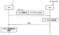
以上、第二の動作モードにおける動作により、図5Aに示すように、ローカルIDの割り当ておよび下位ECU接続構成の診断を行うことができる。ここで、上位ECUにおける処理を単純化するためには、図5Bに示すように、ローカルIDの割り当てと下位ECU接続構成の診断を別々の通信で行うこともできる。しかしこの方法をとった場合、各下位ECUとの通信を2回ずつ行う必要があり、時間がかかってしまう。一般に、車載ECUではキーONからシステムの立ち上がり完了までを短い時間で行うことが求められる。これを実現するには下位ECUとの通信時間をできるだけ短くする必要があり、本実施例で述べたように、ローカルIDの割り当てと下位ECU接続構成の診断を同じ通信にて行うことが有効である。
以上、第二の動作モードにおける動作により、図5Aに示すように、ローカルIDの割り当ておよび下位ECU接続構成の診断を行うことができる。ここで、上位ECUにおける処理を単純化するためには、図5Bに示すように、ローカルIDの割り当てと下位ECU接続構成の診断を別々の通信で行うこともできる。しかしこの方法をとった場合、各下位ECUとの通信を2回ずつ行う必要があり、時間がかかってしまう。一般に、車載ECUではキーONからシステムの立ち上がり完了までを短い時間で行うことが求められる。これを実現するには下位ECUとの通信時間をできるだけ短くする必要があり、本実施例で述べたように、ローカルIDの割り当てと下位ECU接続構成の診断を同じ通信にて行うことが有効である。
すなわち、上位ECU1は、固有IDより短いローカルIDを用いて下位ECU31~33と通信を行うため、通信データ量が小さくなり、通信時間が短くなる。その結果、システムの起動時間が短くなる。
以上説明したように、本実施形態によれば、通信効率を向上することができる。その結果、システムの起動時間が短くなる。
なお、本発明は上記した実施形態に限定されるものではなく、様々な変形例が含まれる。例えば、上述した実施形態は本発明を分かりやすく説明するために詳細に説明したものであり、必ずしも説明した全ての構成を備えるものに限定されるものではない。
また、上記の各構成、機能等は、それらの一部又は全部を、例えば集積回路で設計する等によりハードウェアで実現してもよい。また、上記の各構成、機能等は、プロセッサ(演算回路)がそれぞれの機能を実現するプログラムを解釈し、実行することによりソフトウェアで実現してもよい。各機能を実現するプログラム、テーブル、ファイル等の情報は、メモリや、ハードディスク、SSD(Solid State Drive)等の記録装置、または、ICカード、SDカード、DVD等の記録媒体に置くことができる。
なお、本発明の実施形態は、以下の態様であってもよい。
(1)固有のIDを有する複数の下位制御装置とバス状の配線で接続され、少なくとも2つの動作モードを有し、第一の動作モードにおいて下位制御装置の固有IDを収集してこれを記憶する電子制御装置において、第二の動作モードでは記憶している前記固有IDを備えた下位制御装置に対して固有IDより短いローカルIDを割り付けることを特徴とする電子制御装置。
(2)(1)に記載の電子制御装置において、前記ローカルIDを割り付ける通信の返信有無をもとに、記憶している前記固有IDを備えた下位制御装置がすべて接続されているかを診断し、正常である場合に下位制御装置との通常通信を開始することを特徴とする電子制御装置。
(3)(1)に記載の電子制御装置において、前記ローカルIDを、各々の前記下位制御装置に接続されたアクチュエータ等の担当機能に応じて決定することを特徴とする電子制御装置。
(4)(1)に記載の電子制御装置において、前記ローカルIDを、各々の前記下位制御装置の前記バス状の配線における接続順序に応じて決定することを特徴とする電子制御装置。
上記(1)~(4)によれば、信頼性の向上に加えて通信効率の向上や起動時間の短縮を実現し、車載用途に適した電子制御装置を提供することができる。
1:上位ECU
2:バス配線
31~33:下位ECU
41~43:アクチュエータ等
51~53:制御対象
6:断線箇所
11:演算回路
12:通信回路
13:不揮発性メモリ
14:下位ECU構成情報
301:演算回路
302:通信回路
303:不揮発性メモリ
304:固有ID
305:揮発性メモリ
306:ローカルID
2:バス配線
31~33:下位ECU
41~43:アクチュエータ等
51~53:制御対象
6:断線箇所
11:演算回路
12:通信回路
13:不揮発性メモリ
14:下位ECU構成情報
301:演算回路
302:通信回路
303:不揮発性メモリ
304:固有ID
305:揮発性メモリ
306:ローカルID
Claims (6)
- バスに接続され、固有の識別子を示す固有IDを有する少なくとも1つの下位制御装置と通信する通信回路と、
メモリと、
前記下位制御装置から前記固有IDを収集し、収集した前記固有IDを前記メモリに記憶する第1の動作モード及び前記固有IDより短い識別子を示すローカルIDを前記下位制御装置に割り付ける第2の動作モードを有する演算回路と、
を備えることを特徴とする電子制御装置。 - 請求項1に記載の電子制御装置であって、
前記演算回路は、
前記第2の動作モードにおいて、前記通信回路を介して前記下位制御装置に前記ローカルIDを送信し、前記通信回路を介して前記下位制御装置から前記ローカルIDを受信したことを示す肯定応答を受信した場合、前記下位制御装置と前記通信回路との間の通信が正常であると診断し、前記肯定応答を受信しない場合、前記下位制御装置と前記通信回路との間の通信が異常であると診断する
ことを特徴とする電子制御装置。 - 請求項2に記載の電子制御装置であって、
前記下位制御装置は複数あり、それぞれの前記下位制御装置はアクチュエータを制御し、
前記演算回路は、
それぞれの前記下位制御装置と前記通信回路との間の通信がすべて正常であると診断した場合、前記下位制御装置と前記通信回路と間で前記アクチュエータの制御に用いられるデータの送受信を開始する
ことを特徴とする電子制御装置。 - 請求項1に記載の電子制御装置であって、
前記演算回路は、
それぞれの前記下位制御装置が制御するアクチュエータの機能に応じて前記ローカルIDを決定する
ことを特徴とする電子制御装置。 - 請求項1に記載の電子制御装置であって、
前記演算回路は、
前記下位制御装置の前記バスにおける接続順序を同定し、
同定した前記接続順序に応じてそれぞれの前記下位制御装置の前記ローカルIDを決定する
ことを特徴とする電子制御装置。 - 請求項1に記載の電子制御装置と複数の下位制御装置を含むシステムであって、
前記電子制御装置の前記演算回路は、
前記通信回路を介してすべての下位制御装置に同時に前記固有IDの取得要求を送信し、
それぞれの前記下位制御装置は、
前記バスに接続される通信回路と、
固有IDを記憶するメモリと、
前記固有IDの取得要求に応答して、前記固有IDに基づいて算出されるタイミングに前記通信回路を介して前記固有IDを前記電子制御装置に送信する演算回路と、を備える
ことを特徴とするシステム。
Applications Claiming Priority (2)
| Application Number | Priority Date | Filing Date | Title |
|---|---|---|---|
| JP2017123539A JP6806636B2 (ja) | 2017-06-23 | 2017-06-23 | 電子制御装置 |
| JP2017-123539 | 2017-06-23 |
Publications (1)
| Publication Number | Publication Date |
|---|---|
| WO2018235439A1 true WO2018235439A1 (ja) | 2018-12-27 |
Family
ID=64735678
Family Applications (1)
| Application Number | Title | Priority Date | Filing Date |
|---|---|---|---|
| PCT/JP2018/017695 Ceased WO2018235439A1 (ja) | 2017-06-23 | 2018-05-08 | 電子制御装置 |
Country Status (2)
| Country | Link |
|---|---|
| JP (1) | JP6806636B2 (ja) |
| WO (1) | WO2018235439A1 (ja) |
Families Citing this family (1)
| Publication number | Priority date | Publication date | Assignee | Title |
|---|---|---|---|---|
| KR20250063505A (ko) * | 2023-11-01 | 2025-05-08 | 주식회사 엘지에너지솔루션 | 배터리 시스템 및 이의 식별자 할당 방법 |
Citations (2)
| Publication number | Priority date | Publication date | Assignee | Title |
|---|---|---|---|---|
| JP2011189863A (ja) * | 2010-03-16 | 2011-09-29 | Railway Technical Research Institute | 列車制御システム、地上装置、及び列車制御方法 |
| JP2012222527A (ja) * | 2011-04-06 | 2012-11-12 | Toyota Motor Corp | 車載ネットワーク、管理ノード、番号付与方法 |
-
2017
- 2017-06-23 JP JP2017123539A patent/JP6806636B2/ja active Active
-
2018
- 2018-05-08 WO PCT/JP2018/017695 patent/WO2018235439A1/ja not_active Ceased
Patent Citations (2)
| Publication number | Priority date | Publication date | Assignee | Title |
|---|---|---|---|---|
| JP2011189863A (ja) * | 2010-03-16 | 2011-09-29 | Railway Technical Research Institute | 列車制御システム、地上装置、及び列車制御方法 |
| JP2012222527A (ja) * | 2011-04-06 | 2012-11-12 | Toyota Motor Corp | 車載ネットワーク、管理ノード、番号付与方法 |
Also Published As
| Publication number | Publication date |
|---|---|
| JP2019009620A (ja) | 2019-01-17 |
| JP6806636B2 (ja) | 2021-01-06 |
Similar Documents
| Publication | Publication Date | Title |
|---|---|---|
| US6684152B2 (en) | Method of initializing a system for open/closed-loop control of the operational sequences of a motor vehicle and a system for carrying out the method | |
| CN101566852B (zh) | 过滤相关诊断故障代码的控制系统和方法 | |
| CN100507861C (zh) | 故障诊断数据记录系统与方法 | |
| EP1284556A1 (en) | A method for initializing a control system and a control system | |
| US8223060B2 (en) | Electric control system and electric control unit | |
| KR102298187B1 (ko) | 디에스아이 프로토콜 기반 자동차 내 센서 장치 작동 방법 | |
| US6904339B2 (en) | Method for coding control devices in means of conveyance | |
| CN105579919A (zh) | 用于自动识别蓄电池管理系统中的控制装置的方法 | |
| US20030023407A1 (en) | Method and device for monitoring the functioning of a system | |
| US20100214119A1 (en) | Method and device for assigning addresses in a system having a plurality of generator units positioned in parallel | |
| CN107005448B (zh) | 通信系统及数据总线 | |
| JP7741338B2 (ja) | データ伝送バスを介してデータ伝送するための通信装置を備えた機器、ならびにこの種の機器を備えたデータ伝送システム | |
| JP6806636B2 (ja) | 電子制御装置 | |
| US7539564B2 (en) | Device and method for central on-board diagnosis for motor vehicles | |
| CN103677926A (zh) | 一种在线配置汽车仪表的系统及其方法 | |
| JP5970563B2 (ja) | 電池制御装置 | |
| JP7627847B2 (ja) | 補助電源システム、モジュール、補助電源制御方法、及びプログラム | |
| CN112543218A (zh) | 用于车辆的通信装置及通信方法 | |
| JP6345447B2 (ja) | 自動車用電子制御装置 | |
| JP5643058B2 (ja) | 車両の故障診断制御装置 | |
| JP7856060B2 (ja) | 診断装置 | |
| CN103368799B (zh) | 经由总线系统传输数据的系统和方法 | |
| JP7710201B2 (ja) | 補助電源システム、モジュール、補助電源制御方法、及びプログラム | |
| JP2009501920A (ja) | 電子装置 | |
| WO2022113155A1 (ja) | 車載用制御システム |
Legal Events
| Date | Code | Title | Description |
|---|---|---|---|
| 121 | Ep: the epo has been informed by wipo that ep was designated in this application |
Ref document number: 18820151 Country of ref document: EP Kind code of ref document: A1 |
|
| NENP | Non-entry into the national phase |
Ref country code: DE |
|
| 122 | Ep: pct application non-entry in european phase |
Ref document number: 18820151 Country of ref document: EP Kind code of ref document: A1 |