WO2018235299A1 - User terminal and wireless communication method - Google Patents
User terminal and wireless communication method Download PDFInfo
- Publication number
- WO2018235299A1 WO2018235299A1 PCT/JP2017/023298 JP2017023298W WO2018235299A1 WO 2018235299 A1 WO2018235299 A1 WO 2018235299A1 JP 2017023298 W JP2017023298 W JP 2017023298W WO 2018235299 A1 WO2018235299 A1 WO 2018235299A1
- Authority
- WO
- WIPO (PCT)
- Prior art keywords
- sequence
- signal
- index
- user terminal
- unit
- Prior art date
Links
Images


Classifications
-
- H—ELECTRICITY
- H04—ELECTRIC COMMUNICATION TECHNIQUE
- H04J—MULTIPLEX COMMUNICATION
- H04J13/00—Code division multiplex systems
- H04J13/16—Code allocation
-
- H—ELECTRICITY
- H04—ELECTRIC COMMUNICATION TECHNIQUE
- H04L—TRANSMISSION OF DIGITAL INFORMATION, e.g. TELEGRAPHIC COMMUNICATION
- H04L5/00—Arrangements affording multiple use of the transmission path
- H04L5/003—Arrangements for allocating sub-channels of the transmission path
- H04L5/0053—Allocation of signaling, i.e. of overhead other than pilot signals
- H04L5/0055—Physical resource allocation for ACK/NACK
-
- H—ELECTRICITY
- H04—ELECTRIC COMMUNICATION TECHNIQUE
- H04L—TRANSMISSION OF DIGITAL INFORMATION, e.g. TELEGRAPHIC COMMUNICATION
- H04L1/00—Arrangements for detecting or preventing errors in the information received
- H04L1/12—Arrangements for detecting or preventing errors in the information received by using return channel
- H04L1/16—Arrangements for detecting or preventing errors in the information received by using return channel in which the return channel carries supervisory signals, e.g. repetition request signals
- H04L1/1607—Details of the supervisory signal
- H04L1/1671—Details of the supervisory signal the supervisory signal being transmitted together with control information
-
- H—ELECTRICITY
- H04—ELECTRIC COMMUNICATION TECHNIQUE
- H04L—TRANSMISSION OF DIGITAL INFORMATION, e.g. TELEGRAPHIC COMMUNICATION
- H04L1/00—Arrangements for detecting or preventing errors in the information received
- H04L1/12—Arrangements for detecting or preventing errors in the information received by using return channel
- H04L1/16—Arrangements for detecting or preventing errors in the information received by using return channel in which the return channel carries supervisory signals, e.g. repetition request signals
- H04L1/1607—Details of the supervisory signal
- H04L1/1692—Physical properties of the supervisory signal, e.g. acknowledgement by energy bursts
-
- H—ELECTRICITY
- H04—ELECTRIC COMMUNICATION TECHNIQUE
- H04L—TRANSMISSION OF DIGITAL INFORMATION, e.g. TELEGRAPHIC COMMUNICATION
- H04L1/00—Arrangements for detecting or preventing errors in the information received
- H04L1/12—Arrangements for detecting or preventing errors in the information received by using return channel
- H04L1/16—Arrangements for detecting or preventing errors in the information received by using return channel in which the return channel carries supervisory signals, e.g. repetition request signals
- H04L1/18—Automatic repetition systems, e.g. Van Duuren systems
- H04L1/1812—Hybrid protocols; Hybrid automatic repeat request [HARQ]
-
- H—ELECTRICITY
- H04—ELECTRIC COMMUNICATION TECHNIQUE
- H04L—TRANSMISSION OF DIGITAL INFORMATION, e.g. TELEGRAPHIC COMMUNICATION
- H04L1/00—Arrangements for detecting or preventing errors in the information received
- H04L1/12—Arrangements for detecting or preventing errors in the information received by using return channel
- H04L1/16—Arrangements for detecting or preventing errors in the information received by using return channel in which the return channel carries supervisory signals, e.g. repetition request signals
- H04L1/18—Automatic repetition systems, e.g. Van Duuren systems
- H04L1/1829—Arrangements specially adapted for the receiver end
- H04L1/1861—Physical mapping arrangements
-
- H—ELECTRICITY
- H04—ELECTRIC COMMUNICATION TECHNIQUE
- H04L—TRANSMISSION OF DIGITAL INFORMATION, e.g. TELEGRAPHIC COMMUNICATION
- H04L27/00—Modulated-carrier systems
- H04L27/26—Systems using multi-frequency codes
- H04L27/2601—Multicarrier modulation systems
- H04L27/2602—Signal structure
- H04L27/26025—Numerology, i.e. varying one or more of symbol duration, subcarrier spacing, Fourier transform size, sampling rate or down-clocking
-
- H—ELECTRICITY
- H04—ELECTRIC COMMUNICATION TECHNIQUE
- H04L—TRANSMISSION OF DIGITAL INFORMATION, e.g. TELEGRAPHIC COMMUNICATION
- H04L27/00—Modulated-carrier systems
- H04L27/26—Systems using multi-frequency codes
- H04L27/2601—Multicarrier modulation systems
- H04L27/2602—Signal structure
- H04L27/261—Details of reference signals
- H04L27/2613—Structure of the reference signals
- H04L27/26136—Pilot sequence conveying additional information
-
- H—ELECTRICITY
- H04—ELECTRIC COMMUNICATION TECHNIQUE
- H04L—TRANSMISSION OF DIGITAL INFORMATION, e.g. TELEGRAPHIC COMMUNICATION
- H04L5/00—Arrangements affording multiple use of the transmission path
- H04L5/003—Arrangements for allocating sub-channels of the transmission path
- H04L5/0053—Allocation of signaling, i.e. of overhead other than pilot signals
Definitions
- the present invention relates to a user terminal and a wireless communication method in a next-generation mobile communication system.
- LTE Long Term Evolution
- LTE-A also referred to as LTE advanced, LTE Rel. 10 or 11 or 12
- LTE Rel. 8 or 9 LTE Successor systems
- FRA Fluture Radio Access
- 5G 5th generation mobile communication system
- 5G + plus
- NR New Radio
- NX New radio access
- FX Fluture generation radio access
- downlink Downlink
- uplink are performed using subframes of 1 ms (also referred to as Transmission Time Interval (TTI)).
- TTI Transmission Time Interval
- UL Uplink
- the subframe is a transmission time unit of one channel-coded data packet, and is a processing unit such as scheduling, link adaptation, and retransmission control (HARQ: Hybrid Automatic Repeat reQuest).
- HARQ Hybrid Automatic Repeat reQuest
- the user terminal may be a UL control channel (for example, PUCCH (Physical Uplink Control Channel)) and / or a UL data channel (for example, Uplink control information (UCI) is transmitted using PUSCH (Physical Uplink Shared Channel).
- UL control channel for example, PUCCH (Physical Uplink Control Channel)
- PUSCH Physical Uplink Shared Channel
- the configuration (format) of the UL control channel is also called a PUCCH format or the like.
- UCI is a scheduling request (SR: Scheduling Request), retransmission control information (Hybrid Automatic Repeat reQuest-Acknowledge) (HARQ-ACK) for DL data (PDSCH: Physical Downlink Shared Channel), ACK / NACK (Negative ACK) ), And at least one of channel state information (CSI: Channel State Information).
- SR Scheduling Request
- HARQ-ACK retransmission control information
- PDSCH Physical Downlink Shared Channel
- ACK / NACK Negative ACK
- CSI Channel State Information
- E-UTRA Evolved Universal Terrestrial Radio Access
- E-UTRAN Evolved Universal Terrestrial Radio Access Network
- Future wireless communication systems eg, 5G, NR are expected to realize various wireless communication services to meet different requirements (eg, ultra high speed, large capacity, ultra low delay, etc.) There is.
- eMBB enhanced Mobile Broad Band
- mMTC massive Machine Type Communication
- URLLC Ultra Reliable and Low Latency Communications
- LTE / NR using various UL signal configurations (UL control channel format) is being considered.
- UL control channel format UL control channel format
- LTE Rel. 13 or earlier when a UL signal transmission method in an existing LTE system (LTE Rel. 13 or earlier) is applied, degradation such as coverage and / or throughput may occur.
- This invention is made in view of this point, and it aims at providing the user terminal and the wireless communication method which can transmit UL signal appropriately in the future wireless communication system.
- a user terminal based on a transmitter configured to transmit a sequence obtained from a reference sequence using a cyclic shift associated with a value of uplink control information, and a parameter notified from a wireless base station.
- a control unit configured to control the determination of the reference sequence and a set including a plurality of cyclic shifts respectively associated with a plurality of candidate values of the uplink control information.
- UL signals can be properly transmitted in a future wireless communication system.
- FIG. 1A and FIG. 1B are diagrams showing an example of sequence-based PUCCH.
- FIGS. 2A to 2D are diagrams showing an example of transmission signal generation processing for sequence based PUCCH. It is a figure which shows an example of CS candidate set.
- FIG. 4A and FIG. 4B are diagrams showing an example of a sequence determination method according to the first embodiment.
- 5A and 5B are diagrams showing an example of a sequence determination method according to the second embodiment. It is a figure which shows an example of CS candidate set for sequence based PUCCH which transmits 1 bit.
- 7A and 7B illustrate an example of a CS candidate set for a sequence-based PUCCH transmitting 2 bits.
- Neurology may mean a set of communication parameters that characterize signal design in a certain radio access technology (RAT), design of the RAT, etc., subcarrier spacing (SCS: SubCarrier-Spacing), symbol length It may be a parameter regarding frequency direction and / or time direction, such as cyclic prefix length and subframe length.
- RAT radio access technology
- SCS SubCarrier-Spacing
- symbol length It may be a parameter regarding frequency direction and / or time direction, such as cyclic prefix length and subframe length.
- the same and / or different time unit eg, subframe, slot, minislot, It has been considered to introduce subslots, transmission time intervals (TTIs), short TTIs (sTTIs), radio frames, and so on.
- TTIs transmission time intervals
- sTTIs short TTIs
- radio frames and so on.
- TTI may represent a unit of time for transmitting and receiving transport blocks, code blocks, and / or codewords of transmission and reception data.
- the time interval (number of symbols) in which the transport block, code block, and / or codeword of data is actually mapped may be shorter than the TTI.
- the TTI includes a predetermined number of symbols (for example, 14 symbols)
- transport blocks, code blocks, and / or codewords of transmission and reception data are transmitted and received in one to a predetermined number of symbol intervals therefrom.
- the number of symbols for transmitting / receiving transport blocks, code blocks, and / or codewords of transmitted / received data is smaller than the number of symbols in TTI, mapping reference signals, control signals, etc. to symbols that do not map data in TTI can do.
- a subframe may be a unit of time having a predetermined length of time (for example, 1 ms) regardless of the terminology used (and / or set) by a user terminal (for example, UE: User Equipment).
- UE User Equipment
- the slot may be a time unit based on the numerology used by the UE. For example, when the subcarrier spacing is 15 kHz or 30 kHz, the number of symbols per slot may be 7 or 14 symbols. When the subcarrier spacing is 60 kHz or more, the number of symbols per slot may be 14 symbols. Also, the slot may include a plurality of mini (sub) slots.
- short PUCCH Physical Uplink Control Channel
- long PUCCH Physical Uplink Control Channel
- a short PUCCH has a predetermined number of symbols (eg, 1, 2 or 3 symbols) in a certain SCS.
- uplink control information UCI: Uplink Control Information
- reference signal RS: Reference Signal
- TDM Time Division Multiplexing
- FDM Frequency Division Multiplexing
- RS may be, for example, a demodulation reference signal (DMRS: DeModulation Reference Signal) used for demodulation of UCI.
- DMRS DeModulation Reference Signal
- the SCS of each symbol of the short PUCCH may be the same as or higher than the SCS of a symbol for a data channel (hereinafter, also referred to as a data symbol).
- the data channel may be, for example, a Physical Downlink Shared Channel (PDSCH), a Physical Uplink Shared Channel (PUSCH), or the like.
- PUCCH may be read as “short PUCCH” or “PUCCH in short duration”.
- the PUCCH may be TDM and / or FDM with a UL data channel (hereinafter also referred to as PUSCH) in a slot. Also, the PUCCH may be TDM and / or FDM with a DL data channel (hereinafter also referred to as PDSCH) and / or a DL control channel (hereinafter referred to as PDCCH: Physical Downlink Control Channel) in a slot.
- PUSCH UL data channel
- PUCCH Physical Downlink Control Channel
- a DMRS-based PUCCH (DMRS-based transmission or DMRS-based PUCCH) that notifies UCI by transmitting a DM signal and UCI with FDM and / or TDM as a short PUCCH transmission method, and UCI without using DMRS.
- a sequence based PUCCH (sequence-based transmission or sequence-based PUCCH) that reports UCI by transmitting a UL signal using a code resource associated with a value of.
- the DMRS-based PUCCH may be referred to as coherent transmission, coherent design, etc. to transmit the PUCCH because it includes RSs for UCI demodulation.
- the sequence-based PUCCH may be referred to as non-coherent transmission, noncoherent design, etc., because it reports UCI on PUCCHs that do not include RS for demodulation of UCI.
- the code resource for the sequence-based PUCCH is a resource capable of code division multiplexing (CDM), and is at least one of a reference sequence, a cyclic shift amount (phase rotation amount), and an OCC (Orthogonal Cover Code) It is also good.
- the cyclic shift may be read as phase rotation.
- Information on time resources, frequency resources, and / or code resources for sequence-based PUCCH may be upper layer signaling (eg, RRC (Radio Resource Control) signaling, MAC (Medium Access Control) signaling, broadcast information (MIB) (Master Information Block), SIB (System Information Block), etc.), physical layer signaling (eg, DCI), or a combination thereof may be notified from the NW (network, eg, base station, gNodeB) to the UE.
- RRC Radio Resource Control
- MAC Medium Access Control
- MIB Master Information Block
- SIB System Information Block
- DCI Physical layer signaling
- the reference sequence may be a Constant Amplitude Zero Auto-Correlation (CAZAC) sequence (e.g., a Zadoff-chu sequence), or 3GPP TS 36.211 ⁇ ⁇ 5.5.1.2 (in particular, Table 5.5. 1.2-1 (Table 5.5.1.2-2) or the like may be a sequence (CG-CAZAC (computer generated CAZAC) sequence) conforming to the CAZAC sequence.
- CAZAC Constant Amplitude Zero Auto-Correlation
- sequence-based PUCCH transmits 2-bit UCI using cyclic shift.
- a plurality of candidates for cyclic shift amounts (phase rotation amounts) allocated to one UE are referred to as a CS candidate set (cyclic shift candidate set, cyclic shift amount pattern, phase rotation amount candidate set, phase rotation amount pattern).
- the phase rotation amount ⁇ 0 - ⁇ 11 may be defined based on at least one of the number of subcarriers M, the number of PRBs, and the sequence length of the reference sequence.
- the cyclic shift candidate set may include two or more phase rotation amounts selected from the phase rotation amounts ⁇ 0 - ⁇ 11 .
- Sequence-based PUCCH reports control information including at least one of ACK / NACK (A / N), CSI, and SR.
- UCI indicating A / N and / or CSI and presence of SR may be called UCI including SR
- UCI indicating A / N and / or CSI and no SR May be called UCI without SR.
- control information indicating A / N and / or CSI is referred to as UCI
- control information indicating SR presence or absence is referred to as SR presence / absence.
- UCI values 0 and 1 may correspond to “NACK” and “ACK”, respectively.
- UCI values 00, 01, 11, 10 correspond to "NACK-NACK”, “NACK-ACK”, “ACK-ACK”, and “ACK-NACK”, respectively. Good.
- the UE when UCI is 2 bits, the UE performs phase rotation of the reference sequence using the phase rotation amount corresponding to the value to be transmitted among the 4 candidates of the 2 bit UCI value. And transmit the phase rotated signal using a given time / frequency resource.
- the time / frequency resources are time resources (eg, subframes, slots, symbols, etc.) and / or frequency resources (eg, carrier frequency, channel band, CC (Component Carrier), PRB, etc.).
- FIG. 2 is a diagram illustrating an example of transmission signal generation processing for sequence-based PUCCH.
- the reference sequence X 0 -X M-1 of sequence length M is phase rotated (cyclically shifted) using the selected phase rotation amount ⁇ , and the phase rotated reference sequence is OFDM (Orthogonal Input to a Frequency Division Multiplexing) transmitter or a DFT-S-OFDM (Discrete Fourier Transform-Spread-Orthogonal Frequency Division Multiplexing) transmitter.
- the UE transmits the output signal from the OFDM transmitter or DFT-S-OFDM transmitter.
- phase rotation amount candidate ⁇ 0 - ⁇ 3 When phase rotation amount candidate ⁇ 0 - ⁇ 3 is associated with UCI information candidate 0-3 and information 0 is notified as UCI, as shown in FIG. 2A, the UE can generate a reference sequence X 0 -X M-1 Are phase rotated using the phase rotation amount ⁇ 0 associated with the information 0. Similarly, when notifying information 1-3 as UCI, the UE associates the reference sequence X 0 -X M-1 with the information 1-3 as shown in FIG. 2B, FIG. 2C and FIG. 2D, respectively. Phase rotation is performed using phase rotation amounts ⁇ 1 , ⁇ 2 and ⁇ 3 .
- the NW may determine the UCI from the received signal using maximum likelihood detection (MLD: may be called correlation detection or correlation detection).
- MLD maximum likelihood detection
- the network generates a replica (phase rotation amount replica) of each phase rotation amount allocated to the user terminal (for example, when the UCI payload length is 2 bits, four pattern phase rotation amount replicas).
- the transmission signal waveform may be generated similarly to the user terminal using the reference sequence and the phase rotation amount replica.
- the network calculates the correlation between the obtained transmission signal waveform and the received signal waveform received from the user terminal for all phase rotation replicas, and estimates that the highest correlation phase rotation replica is transmitted. You may
- the network is obtained by performing phase rotation of the phase rotation amount replica on the reference sequence of the transmission signal for each element of the received signal sequence (M complex number sequences) after DFT of size M. It is assumed that the phase rotation replica having the largest absolute value (or the square of the absolute value) of the sum of the M obtained sequences is sent by multiplying the complex conjugate of the transmitted signal sequence (M complex sequences) by multiplication. It may be assumed.
- the network generates transmit signal replicas for the maximum allocation number (12 in the case of 1 PRB) of phase rotation amount, and estimates the phase rotation amount having the highest correlation with the received signal by the same operation as the above MLD. You may When a phase rotation amount other than the allocated phase rotation amount is estimated, it may be estimated that the phase rotation amount closest to the estimated phase rotation amount among the allocated phase rotation amounts is transmitted.
- the base station determines, for example, the UCI value and the presence or absence of SR by performing MLD on the received sequence-based PUCCH.
- the number of cell IDs is 504, and a reference signal (for example, DMRS) associated with PUCCH or PUSCH is selected from 30 sequences according to the cell ID.
- a reference signal for example, DMRS
- the number of cell IDs increases to about 1000 (about twice). With the increase of cell ID, it is preferable to increase the number of sequences used for sequence-based PUCCH.
- the number of base sequences used for reference signals less than 6 PRBs is 30.
- CCS computer generated sequence
- the problem is how to set a large number of sequences used for uplink. Therefore, the present inventors examined a method of setting a sequence for uplink, and reached the present invention.
- This method can be applied to a signal using a sequence obtained by cyclic shift of a reference sequence.
- this method may be applied to the sequence used for sequence based PUCCH, or may be applied to the sequence used for reference signal (eg DMRS) associated with PUCCH or PUSCH.
- DMRS reference signal
- the UE determines a reference sequence and a CS candidate set to be used for sequence-based PUCCH based on the sequence index (number) i notified from the NW.
- the sequence index i may be configured to the UE via higher layer signaling.
- the UE may determine, based on the sequence index i, a reference sequence index j indicating a reference sequence and a CS candidate set index Y indicating a CS candidate set.
- the number of CS candidates (number of UCI value candidates) R to be allocated to each UE is 4.
- the number of usable CS candidate sets S is three.
- the number of usable sequences (maximum number of CDM sequences to be subjected to CDM) N is M ⁇ S.
- the reference sequence number M is 30, and the CS candidate set number S is 3, the usable sequence number N is 90.
- NW allocating one of the 90 sequences to the UE, sequence-based PUCCHs from multiple UEs can be CDM on the same time / frequency resource (symbol / PRB).
- the UE may determine the CS candidate set index Y based on the parameter m and the CS candidate set number S.
- m may be determined by the UE based on a cell ID (cell identifier, cell index), and m may be notified by higher layer signaling.
- m is Mod (cell ID, S).
- Mod (a, b) represents the remainder of a by b (modulo, remainder of a divided by b).
- the UE may determine the CS candidate set determination method based on the range to which the sequence index i belongs. Possible values of the sequence index i may be 0 to S ⁇ M ⁇ 1 using the number of reference sequences M and the number S of CS candidate sets. In this case, the range of the sequence index i may be divided into S partial ranges including M sequence indexes, and a CS candidate set determination method corresponding to each partial range may be defined. Each CS candidate set determination method may be expressed by an equation using m and the CS candidate set number S.
- a partial range corresponding to the partial range index p is p ⁇ M to (p + 1) ⁇ M ⁇ 1, and CS corresponding to the partial range
- a value smaller than M may be used, and instead of the CS candidate set number S, a value smaller than S may be used.
- the UE may assume that the sequence index i is one of 0 to 89.
- the UE may determine the reference sequence index j based on the sequence index i and the reference sequence number M.
- the reference sequence index j is Mod (i, M).
- the UE can prevent the same CS candidate set from being used in two adjacent cells by determining the CS candidate set based on the cell ID. Therefore, it is possible to keep the cross-correlation of the two cell sequences low, and prevent the deterioration of the communication quality of the sequence-based PUCCH.
- FIG. 4 shows a method of determining a sequence in a case where a reference sequence number M is 30, a UCI payload length is 2 bits, and sequence-based PUCCHs are arranged in each PRB of 10 consecutive PRBs in one symbol.
- the NW sets the range of the sequence index assigned to the UE to 0 to 29 (sets the number of usable sequences N to 30), thereby suppressing the cross correlation between the sequences to a low degree, and the sequence base It is possible to prevent the deterioration of communication quality of PUCCH.
- the CS candidate set index is based on the cell ID, the probability that the CS candidate set matches between adjacent cells can be suppressed (the distance between cells using the same CS candidate set can be increased), and the cross correlation of the sequences between cells Can be kept low.
- the distance (phase) between CS candidates can be separated, and the cross-correlation of the series in the cell can be reduced even when the frequency selectivity is severe. be able to.
- the NW sets a plurality of CS candidate sets in one cell by setting the range of the sequence index assigned to the UE to 0 to 89 (setting the number N of available sequences to 90). And the number of multiplexed UEs can be increased.
- a CS candidate set is determined based on the range to which the notified sequence index belongs. Therefore, the case where different CS candidate sets are used in the same cell occurs.
- the reference sequence index j is a remainder of the reference sequence of the sequence index i.
- the NW can set the sequence index i flexibly according to the situation.
- the UE may determine the parameter m based on the cell ID, the PRB index (PRB number), the symbol index (symbol number), and / or the beam index.
- the PRB index may be the smallest PRB index or the largest PRB index in the frequency resource of sequence-based PUCCH.
- the symbol index may be a symbol index indicating a time resource of sequence-based PUCCH.
- the beam index may be an index indicating a beam used for transmission of sequence based PUCCH.
- information indicating other frequency resources may be used.
- information indicating other time resources may be used.
- the parameter m may be obtained based on the combination of the cell ID, the PRB index, and the symbol index.
- the parameter m may be obtained by Mod (cell ID + PRB index + symbol index, N).
- the reference sequence index j and / or the CS candidate set index Y may hop based on a predetermined hopping pattern.
- the number of CS candidates allocated to each UE is 2. Since the total number of CS candidates is 12, the number S of usable CS candidate sets is 6.
- the reference sequence number M may be configured in the UE via higher layer signaling.
- the bandwidth of the sequence-based PUCCH (the number of PUCCH PRBs) is 1 to 5 PRBs, 30 or 60 may be set as the reference sequence number M.
- the UE may assume that the reference sequence number M is 30. If the bandwidth of sequence-based PUCCH is 6 PRBs or more, the UE may assume that the number of reference sequences M is 60.
- the UE may determine the reference sequence number M based on the PUCCH PRB number or sequence length set by the NW.
- the UE may assume that the reference sequence number M is 30. Otherwise, the UE may assume that the reference sequence number M is 60. For example, when the number of PUCCH PRBs is 1 to 2 PRBs, the UE assumes that the reference sequence number M is 30, otherwise, the reference sequence number M is the maximum prime number -1 or less of the reference sequence length. It may be assumed that Specifically, the UE assumes that the reference sequence is CGS of LTE when the number of PUCCH PRBs is 1 to 2 PRBs, and assumes that the reference sequence is a Zadoff-Chu sequence otherwise. It is also good.
- the NW may determine the reference sequence index j and the CS candidate set index Y from the notified sequence index i in the same manner as the UE. By this operation, the NW can specify the reference sequence and the CS candidate set, and receive the sequence based PUCCH.
- the NW reduces the probability of sequence duplication within and / or between cells by setting one of many combinations of reference sequences and CS candidate sets to the UE. can do.
- the available sequence number N is configured in the UE via higher layer signaling and / or broadcast information.
- the available sequence number N can be reworded as the number of available combinations among the combinations of the reference sequence and the CS candidate set.
- the available sequence number N may be based on the reference sequence number M.
- any one of M, 2M, and 3M may be designated from NW as N.
- the NW may notify the UE of information indicating N or may notify the UE of information indicating N / M.
- the number N of usable sequences may be t ⁇ M.
- the UE may determine the sequence index i in the range of 0 to N ⁇ 1 based on at least one of the cell ID, the PRB index, the symbol index, and the beam index.
- sequence index i may be obtained by Mod (cell ID, N), may be obtained by Mod (PRB index, N), or may be obtained by Mod (symbol index, N) .
- sequence index i may be obtained based on the combination of the cell ID, the PRB index, and the symbol index.
- the sequence index i may be obtained by Mod (cell ID + PRB index + symbol index, N).
- the UE may determine the CS candidate set index Y based on the cell ID.
- the CS candidate set index Y may be Mod (cell ID, S).
- the UE may determine the CS candidate set index Y based on at least one of the cell ID, the PRB index, the symbol index, and the beam index.
- the CS candidate set index Y may be Mod (cell ID + PRB index + symbol index, S).
- the UE may determine the reference sequence index j based on the sequence index i and the reference sequence number M.
- the reference sequence index j is Mod (i, M).
- the NW can suppress the cross correlation between the sequences low and prevent the deterioration of the communication quality of the sequence-based PUCCH. Also, the NW can increase the number of multiplexed UEs by setting the number N of usable sequences larger than a predetermined value (for example, N is 3M).
- the NW can flexibly set the number N of usable sequences depending on the situation.
- the reference sequence index j and / or the CS candidate set index Y may hop based on a predetermined hopping pattern.
- FIG. 5 shows that in a symbol in which the reference sequence number M is 30, the UCI payload length is 2 bits, the usable sequence number N is 30, and the symbol index is 13 symbols, each PRB of 10 consecutive PRBs A method of determining a sequence when a base PUCCH is deployed is shown.
- the sequence index i is determined by Mod (cell ID + PRB index + symbol index, N)
- the CS candidate set index Y is determined by Mod (cell ID, S).
- FIG. 5A shows a cell whose cell ID is 3 and FIG. 5B shows a cell whose cell ID is 5.
- the CS candidate set index Y is different among these cells.
- the sequence index i is different even if the PRB index and the symbol index are identical to each other.
- the reference sequence index j in this case is equal to the sequence index i.
- the range of the sequence index i is 0 to 89, which may cause a case where different CS candidate sets are used in the same cell.
- the NW may determine the reference sequence index j and the CS candidate set index Y based on the notified available number of available sequences N and the cell ID and / or the resources of the sequence-based PUCCH. By this operation, the NW can specify the reference sequence and the CS candidate set, and receive the sequence based PUCCH.
- the UE can reduce the amount of information of notification by NW by determining the sequence index i, compared to the first embodiment.
- the CS candidate set index is set from the NW to the UE via higher layer signaling.
- a CS candidate set index Y and a reference sequence index j may be respectively set.
- the range of CS candidate set index Y is 0 to S-1
- the range of reference sequence index j is 0 to M-1.
- the NW may limit the range of the CS candidate set index Y notified to the UE. For example, by limiting the range of the CS candidate set index Y by the NW, it is possible to suppress the cross correlation between the sequences low and prevent the deterioration of the communication quality of the sequence-based PUCCH. For example, the number of multiplexed UEs can be increased by not limiting the range of the CS candidate set index Y by the NW.
- the NW can flexibly set the CS candidate set to the UE depending on the situation.
- the NW limits the CS candidate set in the corresponding cell to # 1, thereby using the series used in the cell and the periphery.
- Cross-correlation with sequences used in cells can be kept low.
- the NW performs a process of assigning a CS candidate set. For example, it is desirable to restrict the CS candidate set to # 1 in one cell, restrict the CS candidate set to # 2 in a neighboring cell, and restrict the CS candidate set to # 3 in another neighboring cell. In order to do so, a plurality of NWs need to share the CS candidate set index to be used outside each cell.
- the NW assigns the CS candidate set index Y and the reference sequence index j to the UE, the influence on the specification is small.
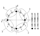
- CS candidate sets for sequence-based PUCCHs of 1 symbol / 1 PRB are shown.
- each CS candidate set includes 2 CS candidates, and the number S of CS candidate sets is 6.
- the distance (phase difference) between CS candidates is the largest.
- CS candidate set # 0 includes ⁇ 0 and ⁇ 6
- CS candidate set # 1 includes ⁇ 1 and ⁇ 7
- CS candidate set # 2 includes ⁇ 2 and ⁇ 8
- CS candidate set # 3 includes ⁇ 3 and ⁇ 9
- CS candidate set # 4 includes ⁇ 4 and ⁇ 10
- CS candidate set # 5 includes ⁇ 5 and ⁇ 11 .
- Two CS candidates in each CS candidate set correspond to UCI values 0 and 1, respectively.
- the interval of CS (phase rotation amount) candidates in each CS candidate set is ⁇ .
- the NW can use this value as a reference signal (e.g., DMRS).
- a reference signal e.g., DMRS
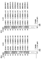
- each CS candidate set includes 4 CS candidates, and is a CS candidate.
- the number of sets S is three.
- the distance (phase difference) between CS candidates is the largest.
- Such a CS candidate set is called a first CS candidate set. That is, the plurality of CS candidates in the first CS candidate set have equal intervals.
- CS candidate set # 0 includes ⁇ 0 , ⁇ 3 , ⁇ 6 and ⁇ 9
- CS candidate set # 1 includes ⁇ 1 , ⁇ 4 , ⁇ 7 and ⁇ 10
- CS candidate set # 2 includes ⁇ 2 , ⁇ 5 , ⁇ 8 and ⁇ 11 .
- Four CS candidates in each CS candidate set correspond to UCI values 00, 01, 11, 10, respectively.
- the interval of CS (phase rotation amount) candidates in each CS candidate set is ⁇ / 2.
- the NW can use this value as a reference signal (e.g., DMRS).
- the NW may perform channel estimation using DMRS, or may demodulate UCI using DMRS.
- each CS candidate set includes 4 CS candidates, and the number S of CS candidate sets is 3.
- the distance (phase difference) between CS candidates corresponding to different UCI values is the longest, and CS candidates corresponding to the presence / absence of SR are adjacent.
- Such a CS candidate set is called a second CS candidate set. That is, the plurality of CS candidates in the second CS candidate set have unequal intervals.
- CS candidate set # 0 includes ⁇ 0 , ⁇ 1 , ⁇ 6 and ⁇ 7
- CS candidate set # 1 includes ⁇ 2 , ⁇ 3 , ⁇ 8 and ⁇ 9
- CS candidate set # 2 includes ⁇ 4 , ⁇ 5 , ⁇ 10 and ⁇ 11 .
- the four CS candidates in each CS candidate set correspond to UCI value 0 and no SR, UCI value 0 and SR, UCI value 1 and SR, UCI value 1 and SR, respectively.
- the interval of CS (phase rotation amount) candidates corresponding to different UCIs is ⁇
- the interval of CS candidates corresponding to the presence or absence of SR is ⁇ / 6.
- the UCI error rate requirement is more stringent than the SR presence / absence error rate requirement.
- the interval between two CS candidates corresponding to different UCI values is larger than the interval between two CS candidates corresponding to the presence / absence of SR, frequency selectivity is strict (channel delay spread In a large environment, the UCI error rate can be reduced compared to the first CS candidate set.
- the NW UE When the sequence-based PUCCH reports UCI and SR presence / absence (for example, when notifying 1 bit UCI and SR presence / absence), the NW UEs the first CS candidate set or the second CS candidate set via higher layer signaling. It may be set to The UE may transmit the sequence based PUCCH using the configured CS candidate set.
- the fifth embodiment shows a method of determining a sequence other than sequence-based PUCCH.
- the UE may determine a sequence for a reference signal (eg, DMRS) associated with PUCCH or PUSCH.
- a reference signal eg, DMRS
- the UE may determine at least one of the sequence index i, the reference sequence index j, and the CS candidate set index Y, as in the first embodiment.
- the UE may determine at least one of the sequence index i, the reference sequence index j, and the CS candidate set index Y, as in the second or third embodiment.
- the UE uses CS candidates associated with the UCI value among the determined CS candidates for sequence-based PUCCH.
- the UE determines a CS candidate to be used for a sequence other than sequence-based PUCCH, and performs cyclic shift of the reference sequence using the determined CS candidate.
- a first CS candidate determination method and a second CS candidate determination method for determining CS candidates will be described.
- the UE may be configured as a CS candidate via higher layer signaling.
- the CS candidate index Z indicating one of CS candidates may be notified from the NW to the UE.
- the CS candidate index Z is one of 0-11.
- the CS candidate set index Y and information for specifying a CS candidate in the CS candidate set may be notified.
- the information specifying the CS candidates may be one of 0 to 3.
- the NW can flexibly set the CS candidate to the UE according to the situation by assigning the CS candidate to the UE.
- the UE may determine the CS candidate index Z based on at least one of the cell ID, the PRB index, the symbol index, and the beam index.
- the PRB index may be the smallest PRB index or the largest PRB index in frequency resources used to transmit a sequence.
- the symbol index may be a symbol index indicating a time resource used to transmit a sequence.
- the beam index may be an index indicating a beam used to transmit a sequence.
- the CS candidate index Z may be determined by Y + S ⁇ Mod (cell ID + symbol index + PRB index, R).
- the UE can reduce the amount of information of notification from the NW by determining the CS candidate.
- the CS candidate is based on the cell ID, the probability that the CS candidate matches between adjacent cells can be suppressed.
- wireless communication system Wireless communication system
- communication is performed using any one or a combination of the wireless communication methods according to the above embodiments of the present invention.
- FIG. 8 is a diagram showing an example of a schematic configuration of a wireless communication system according to an embodiment of the present invention.
- the radio communication system 1 applies carrier aggregation (CA) and / or dual connectivity (DC) in which a plurality of basic frequency blocks (component carriers) each having a system bandwidth (for example, 20 MHz) of the LTE system as one unit are integrated. can do.
- CA carrier aggregation
- DC dual connectivity
- the wireless communication system 1 includes LTE (Long Term Evolution), LTE-A (LTE-Advanced), LTE-B (LTE-Beyond), SUPER 3G, IMT-Advanced, 4G (4th generation mobile communication system), and 5G. It may be called (5th generation mobile communication system), NR (New Radio), FRA (Future Radio Access), New-RAT (Radio Access Technology) or the like, or may be called a system for realizing these.
- the radio communication system 1 includes a radio base station 11 forming a macrocell C1 with a relatively wide coverage, and radio base stations 12 (12a to 12c) disposed in the macrocell C1 and forming a small cell C2 narrower than the macrocell C1. And. Moreover, the user terminal 20 is arrange
- the user terminal 20 can be connected to both the radio base station 11 and the radio base station 12. It is assumed that the user terminal 20 simultaneously uses the macro cell C1 and the small cell C2 by CA or DC. Also, the user terminal 20 may apply CA or DC using a plurality of cells (CCs) (for example, 5 or less CCs, 6 or more CCs).
- CCs cells
- Communication can be performed between the user terminal 20 and the radio base station 11 using a relatively low frequency band (for example, 2 GHz) and a narrow bandwidth carrier (also called an existing carrier, legacy carrier, etc.).
- a carrier having a wide bandwidth in a relatively high frequency band for example, 3.5 GHz, 5 GHz, etc.
- the configuration of the frequency band used by each wireless base station is not limited to this.
- a wired connection for example, an optical fiber conforming to a Common Public Radio Interface (CPRI), an X2 interface, etc.
- a wireless connection Can be configured.
- the radio base station 11 and each radio base station 12 are connected to the higher station apparatus 30 and connected to the core network 40 via the higher station apparatus 30.
- the upper station apparatus 30 includes, for example, an access gateway apparatus, a radio network controller (RNC), a mobility management entity (MME), and the like, but is not limited thereto. Further, each wireless base station 12 may be connected to the higher station apparatus 30 via the wireless base station 11.
- RNC radio network controller
- MME mobility management entity
- the radio base station 11 is a radio base station having a relatively wide coverage, and may be called a macro base station, an aggregation node, an eNB (eNodeB), a transmission / reception point, or the like.
- the radio base station 12 is a radio base station having local coverage, and is a small base station, a micro base station, a pico base station, a femto base station, a HeNB (Home eNodeB), an RRH (Remote Radio Head), transmission and reception It may be called a point or the like.
- the radio base stations 11 and 12 are not distinguished, they are collectively referred to as the radio base station 10.
- Each user terminal 20 is a terminal compatible with various communication schemes such as LTE and LTE-A, and may include not only mobile communication terminals (mobile stations) but also fixed communication terminals (fixed stations).
- orthogonal frequency division multiple access (OFDMA) is applied to the downlink as a radio access scheme, and single carrier frequency division multiple access (SC-FDMA: single carrier) to the uplink.
- SC-FDMA single carrier frequency division multiple access
- Frequency Division Multiple Access and / or OFDMA is applied.
- OFDMA is a multicarrier transmission scheme in which a frequency band is divided into a plurality of narrow frequency bands (subcarriers) and data is mapped to each subcarrier to perform communication.
- SC-FDMA is a single carrier transmission method that reduces interference between terminals by dividing the system bandwidth into bands of one or continuous resource blocks for each terminal and using different bands by a plurality of terminals.
- the uplink and downlink radio access schemes are not limited to these combinations, and other radio access schemes may be used.
- a downlink shared channel (PDSCH: Physical Downlink Shared Channel) shared by each user terminal 20, a broadcast channel (PBCH: Physical Broadcast Channel), a downlink L1 / L2 control channel, etc. are used as downlink channels. Used. User data, upper layer control information, SIB (System Information Block) and the like are transmitted by the PDSCH. Also, a MIB (Master Information Block) is transmitted by the PBCH.
- PDSCH Physical Downlink Shared Channel
- PBCH Physical Broadcast Channel
- SIB System Information Block
- MIB Master Information Block
- the downlink L1 / L2 control channel includes PDCCH (Physical Downlink Control Channel), EPDCCH (Enhanced Physical Downlink Control Channel), PCFICH (Physical Control Format Indicator Channel), PHICH (Physical Hybrid-ARQ Indicator Channel) and the like.
- Downlink control information (DCI) including scheduling information of PDSCH and / or PUSCH is transmitted by PDCCH.
- scheduling information may be notified by DCI.
- DCI scheduling DL data reception may be referred to as DL assignment
- DCI scheduling UL data transmission may be referred to as UL grant.
- the number of OFDM symbols used for PDCCH is transmitted by PCFICH.
- Delivery confirmation information (for example, also referred to as retransmission control information, HARQ-ACK, or ACK / NACK) of HARQ (Hybrid Automatic Repeat reQuest) for the PUSCH is transmitted by the PHICH.
- the EPDCCH is frequency division multiplexed with a PDSCH (downlink shared data channel), and is used for transmission such as DCI, similarly to the PDCCH.
- an uplink shared channel (PUSCH: Physical Uplink Shared Channel) shared by each user terminal 20, an uplink control channel (PUCCH: Physical Uplink Control Channel), a random access channel (PRACH: Physical Random Access Channel) or the like is used.
- User data, upper layer control information, etc. are transmitted by PUSCH.
- downlink radio quality information (CQI: Channel Quality Indicator), delivery confirmation information, scheduling request (SR: Scheduling Request), etc. are transmitted by the PUCCH.
- the PRACH transmits a random access preamble for establishing a connection with a cell.
- a cell-specific reference signal (CRS: Cell-specific Reference Signal), a channel state information reference signal (CSI-RS: Channel State Information-Reference Signal), a demodulation reference signal (DMRS: DeModulation Reference Signal, positioning reference signal (PRS), etc.
- CRS Cell-specific Reference Signal
- CSI-RS Channel State Information-Reference Signal
- DMRS DeModulation Reference Signal
- PRS positioning reference signal
- SRS Sounding Reference Signal
- DMRS demodulation reference signal
- PRS positioning reference signal
- DMRS Demodulation reference signal
- PRS positioning reference signal
- FIG. 9 is a diagram showing an example of the entire configuration of a radio base station according to an embodiment of the present invention.
- the radio base station 10 includes a plurality of transmitting and receiving antennas 101, an amplifier unit 102, a transmitting and receiving unit 103, a baseband signal processing unit 104, a call processing unit 105, and a transmission path interface 106.
- each of the transmitting and receiving antenna 101, the amplifier unit 102, and the transmitting and receiving unit 103 may be configured to include one or more.
- User data transmitted from the radio base station 10 to the user terminal 20 by downlink is input from the higher station apparatus 30 to the baseband signal processing unit 104 via the transmission path interface 106.
- the baseband signal processing unit 104 performs packet data convergence protocol (PDCP) layer processing, user data division / combination, RLC layer transmission processing such as RLC (Radio Link Control) retransmission control, and MAC (Medium Access) for user data.
- Control Transmission processing such as retransmission control (for example, HARQ transmission processing), scheduling, transmission format selection, channel coding, inverse fast Fourier transform (IFFT) processing, precoding processing, etc. It is transferred to 103. Further, transmission processing such as channel coding and inverse fast Fourier transform is also performed on the downlink control signal and transferred to the transmission / reception unit 103.
- the transmission / reception unit 103 converts the baseband signal output from the baseband signal processing unit 104 for each antenna into a radio frequency band and transmits the baseband signal.
- the radio frequency signal frequency-converted by the transmitting and receiving unit 103 is amplified by the amplifier unit 102 and transmitted from the transmitting and receiving antenna 101.
- the transmission / reception unit 103 can be configured of a transmitter / receiver, a transmission / reception circuit, or a transmission / reception device described based on the common recognition in the technical field according to the present invention.
- the transmitting and receiving unit 103 may be configured as an integrated transmitting and receiving unit, or may be configured from a transmitting unit and a receiving unit.
- the radio frequency signal received by the transmission / reception antenna 101 is amplified by the amplifier unit 102.
- the transmitting and receiving unit 103 receives the upstream signal amplified by the amplifier unit 102.
- the transmission / reception unit 103 frequency-converts the received signal into a baseband signal and outputs the result to the baseband signal processing unit 104.
- the baseband signal processing unit 104 performs Fast Fourier Transform (FFT) processing, Inverse Discrete Fourier Transform (IDFT) processing, and error correction on user data included in the input upstream signal. Decoding, reception processing of MAC retransmission control, and reception processing of RLC layer and PDCP layer are performed, and are transferred to the higher station apparatus 30 via the transmission path interface 106.
- the call processing unit 105 performs call processing (setting, release, etc.) of the communication channel, state management of the radio base station 10, management of radio resources, and the like.
- the transmission path interface 106 transmits and receives signals to and from the higher station apparatus 30 via a predetermined interface. Also, the transmission path interface 106 transmits / receives signals (backhaul signaling) to / from the other wireless base station 10 via an inter-base station interface (for example, an optical fiber conforming to CPRI (Common Public Radio Interface), X2 interface). May be
- an inter-base station interface for example, an optical fiber conforming to CPRI (Common Public Radio Interface), X2 interface.
- the transmitting / receiving unit 103 may receive a sequence (for example, sequence-based PUCCH) obtained from the reference sequence using a cyclic shift associated with the value of uplink control information (UCI).
- a sequence for example, sequence-based PUCCH
- UCI uplink control information
- the transmission / reception unit 103 may use parameters (for example, sequence index, usable number of available sequences, cell ID, and information indicating a frequency resource of sequence-based PUCCH) used to determine a reference sequence and / or CS candidate set for the sequence-based PUCCH And / or information indicating a time resource of sequence-based PUCCH) may be transmitted to the user terminal 20.
- parameters for example, sequence index, usable number of available sequences, cell ID, and information indicating a frequency resource of sequence-based PUCCH used to determine a reference sequence and / or CS candidate set for the sequence-based PUCCH And / or information indicating a time resource of sequence-based PUCCH
- FIG. 10 is a diagram showing an example of a functional configuration of a wireless base station according to an embodiment of the present invention.
- the functional block of the characteristic part in this embodiment is mainly shown, and suppose that the wireless base station 10 also has another functional block required for wireless communication.
- the baseband signal processing unit 104 at least includes a control unit (scheduler) 301, a transmission signal generation unit 302, a mapping unit 303, a reception signal processing unit 304, and a measurement unit 305. Note that these configurations may be included in the wireless base station 10, and some or all of the configurations may not be included in the baseband signal processing unit 104.
- a control unit (scheduler) 301 performs control of the entire radio base station 10.
- the control unit 301 can be configured of a controller, a control circuit, or a control device described based on the common recognition in the technical field according to the present invention.
- the control unit 301 controls, for example, generation of a signal by the transmission signal generation unit 302, assignment of a signal by the mapping unit 303, and the like. Further, the control unit 301 controls reception processing of a signal by the reception signal processing unit 304, measurement of a signal by the measurement unit 305, and the like.
- the control unit 301 schedules (for example, resources) system information, downlink data signals (for example, signals transmitted on PDSCH), downlink control signals (for example, signals transmitted on PDCCH and / or EPDCCH, delivery confirmation information, etc.) Control allocation). Further, the control unit 301 controls generation of the downlink control signal, the downlink data signal, and the like based on the result of determining whether the retransmission control for the uplink data signal is necessary or not. The control unit 301 also controls scheduling of synchronization signals (for example, PSS (Primary Synchronization Signal) / SSS (Secondary Synchronization Signal), downlink reference signals (for example, CRS, CSI-RS, DMRS) and the like.
- PSS Primary Synchronization Signal
- SSS Synchronization Signal
- the control unit 301 may use an uplink data signal (for example, a signal transmitted on PUSCH), an uplink control signal (for example, a signal transmitted on PUCCH and / or PUSCH, delivery confirmation information, etc.), a random access preamble (for example, PRACH). Control the scheduling of transmitted signals, uplink reference signals, etc.
- an uplink data signal for example, a signal transmitted on PUSCH
- an uplink control signal for example, a signal transmitted on PUCCH and / or PUSCH, delivery confirmation information, etc.
- a random access preamble for example, PRACH
- the transmission signal generation unit 302 generates a downlink signal (downlink control signal, downlink data signal, downlink reference signal or the like) based on an instruction from the control unit 301, and outputs the downlink signal to the mapping unit 303.
- the transmission signal generation unit 302 can be configured from a signal generator, a signal generation circuit or a signal generation device described based on the common recognition in the technical field according to the present invention.
- the transmission signal generation unit 302 generates, for example, DL assignment for notifying downlink data allocation information and / or UL grant for notifying uplink data allocation information, based on an instruction from the control unit 301.
- DL assignment and UL grant are both DCI and follow DCI format.
- coding processing and modulation processing are performed on the downlink data signal according to a coding rate, a modulation method, and the like determined based on channel state information (CSI: Channel State Information) and the like from each user terminal 20.
- CSI Channel State Information
- Mapping section 303 maps the downlink signal generated by transmission signal generation section 302 to a predetermined radio resource based on an instruction from control section 301, and outputs the mapped downlink signal to transmission / reception section 103.
- the mapping unit 303 may be configured of a mapper, a mapping circuit or a mapping device described based on the common recognition in the technical field according to the present invention.
- the reception signal processing unit 304 performs reception processing (for example, demapping, demodulation, decoding, and the like) on the reception signal input from the transmission / reception unit 103.
- the reception signal is, for example, an uplink signal (uplink control signal, uplink data signal, uplink reference signal, etc.) transmitted from the user terminal 20.
- the received signal processing unit 304 can be configured from a signal processor, a signal processing circuit or a signal processing device described based on the common recognition in the technical field according to the present invention.
- the reception signal processing unit 304 outputs the information decoded by the reception process to the control unit 301. For example, when the PUCCH including the HARQ-ACK is received, the HARQ-ACK is output to the control unit 301. Further, the reception signal processing unit 304 outputs the reception signal and / or the signal after reception processing to the measurement unit 305.
- the measurement unit 305 performs measurement on the received signal.
- the measuring unit 305 can be configured from a measuring device, a measuring circuit or a measuring device described based on the common recognition in the technical field according to the present invention.
- the measurement unit 305 may perform Radio Resource Management (RRM) measurement, Channel State Information (CSI) measurement, and the like based on the received signal.
- the measurement unit 305 may use received power (for example, RSRP (Reference Signal Received Power)), received quality (for example, RSRQ (Reference Signal Received Quality), SINR (Signal to Interference plus Noise Ratio)), signal strength (for example, RSSI (for example). Received Signal Strength Indicator), propagation path information (eg, CSI), etc. may be measured.
- the measurement result may be output to the control unit 301.
- control unit 301 may assign a radio resource for sequence-based PUCCH. Also, the control unit 301 may assign a sequence index for sequence-based PUCCH.
- FIG. 11 is a diagram showing an example of the entire configuration of a user terminal according to an embodiment of the present invention.
- the user terminal 20 includes a plurality of transmitting and receiving antennas 201, an amplifier unit 202, a transmitting and receiving unit 203, a baseband signal processing unit 204, and an application unit 205.
- each of the transmitting and receiving antenna 201, the amplifier unit 202, and the transmitting and receiving unit 203 may be configured to include one or more.
- the radio frequency signal received by the transmission / reception antenna 201 is amplified by the amplifier unit 202.
- the transmitting and receiving unit 203 receives the downlink signal amplified by the amplifier unit 202.
- the transmission / reception unit 203 frequency-converts the received signal into a baseband signal and outputs the result to the baseband signal processing unit 204.
- the transmission / reception unit 203 can be configured of a transmitter / receiver, a transmission / reception circuit or a transmission / reception device described based on the common recognition in the technical field according to the present invention.
- the transmission / reception unit 203 may be configured as an integrated transmission / reception unit, or may be configured from a transmission unit and a reception unit.
- the baseband signal processing unit 204 performs reception processing of FFT processing, error correction decoding, retransmission control, and the like on the input baseband signal.
- the downlink user data is transferred to the application unit 205.
- the application unit 205 performs processing on a layer higher than the physical layer and the MAC layer. Moreover, broadcast information may also be transferred to the application unit 205 among downlink data.
- uplink user data is input from the application unit 205 to the baseband signal processing unit 204.
- the baseband signal processing unit 204 performs transmission processing of retransmission control (for example, transmission processing of HARQ), channel coding, precoding, discrete Fourier transform (DFT) processing, IFFT processing, etc. It is transferred to 203.
- the transmission / reception unit 203 converts the baseband signal output from the baseband signal processing unit 204 into a radio frequency band and transmits it.
- the radio frequency signal frequency-converted by the transmitting and receiving unit 203 is amplified by the amplifier unit 202 and transmitted from the transmitting and receiving antenna 201.
- the transmission / reception unit 203 may transmit a sequence (for example, sequence-based PUCCH) obtained from the reference sequence using a cyclic shift associated with the value of uplink control information (UCI).
- a sequence for example, sequence-based PUCCH
- UCI uplink control information
- the transmission / reception unit 203 may receive, from the radio base station 10, a reference sequence for sequence-based PUCCH and / or parameters used for determining a CS candidate set.
- FIG. 12 is a diagram showing an example of a functional configuration of a user terminal according to an embodiment of the present invention.
- the functional block of the characteristic part in this embodiment is mainly shown, and it is assumed that the user terminal 20 also has another functional block required for wireless communication.
- the baseband signal processing unit 204 included in the user terminal 20 at least includes a control unit 401, a transmission signal generation unit 402, a mapping unit 403, a reception signal processing unit 404, and a measurement unit 405. Note that these configurations may be included in the user terminal 20, and some or all of the configurations may not be included in the baseband signal processing unit 204.
- the control unit 401 controls the entire user terminal 20.
- the control unit 401 can be configured of a controller, a control circuit, or a control device described based on the common recognition in the technical field according to the present invention.
- the control unit 401 controls, for example, signal generation by the transmission signal generation unit 402, assignment of signals by the mapping unit 403, and the like. Further, the control unit 401 controls reception processing of a signal by the reception signal processing unit 404, measurement of a signal by the measurement unit 405, and the like.
- the control unit 401 acquires the downlink control signal and the downlink data signal transmitted from the radio base station 10 from the reception signal processing unit 404.
- the control unit 401 controls the generation of the uplink control signal and / or the uplink data signal based on the result of determining the necessity of the retransmission control for the downlink control signal and / or the downlink data signal.
- control unit 401 When the control unit 401 acquires various types of information notified from the radio base station 10 from the received signal processing unit 404, the control unit 401 may update parameters used for control based on the information.
- the transmission signal generation unit 402 generates an uplink signal (uplink control signal, uplink data signal, uplink reference signal or the like) based on an instruction from the control unit 401, and outputs the uplink signal to the mapping unit 403.
- the transmission signal generation unit 402 can be configured from a signal generator, a signal generation circuit, or a signal generation device described based on the common recognition in the technical field according to the present invention.
- the transmission signal generation unit 402 generates, for example, an uplink control signal related to delivery confirmation information, channel state information (CSI), and the like based on an instruction from the control unit 401. Further, the transmission signal generation unit 402 generates an uplink data signal based on an instruction from the control unit 401. For example, when the downlink control signal notified from the radio base station 10 includes a UL grant, the transmission signal generation unit 402 is instructed by the control unit 401 to generate an uplink data signal.
- CSI channel state information
- Mapping section 403 maps the uplink signal generated by transmission signal generation section 402 to a radio resource based on an instruction from control section 401, and outputs the uplink signal to transmission / reception section 203.
- the mapping unit 403 may be configured of a mapper, a mapping circuit or a mapping device described based on the common recognition in the technical field according to the present invention.
- the reception signal processing unit 404 performs reception processing (for example, demapping, demodulation, decoding, and the like) on the reception signal input from the transmission / reception unit 203.
- the reception signal is, for example, a downlink signal (a downlink control signal, a downlink data signal, a downlink reference signal, or the like) transmitted from the radio base station 10.
- the received signal processing unit 404 can be composed of a signal processor, a signal processing circuit or a signal processing device described based on the common recognition in the technical field according to the present invention. Also, the received signal processing unit 404 can constitute a receiving unit according to the present invention.
- the reception signal processing unit 404 outputs the information decoded by the reception process to the control unit 401.
- the received signal processing unit 404 outputs, for example, broadcast information, system information, RRC signaling, DCI, and the like to the control unit 401. Further, the reception signal processing unit 404 outputs the reception signal and / or the signal after reception processing to the measurement unit 405.
- the measurement unit 405 performs measurement on the received signal.
- the measuring unit 405 can be configured of a measuring device, a measuring circuit or a measuring device described based on the common recognition in the technical field according to the present invention.
- the measurement unit 405 may perform RRM measurement, CSI measurement, and the like based on the received signal.
- the measurement unit 405 may measure reception power (for example, RSRP), reception quality (for example, RSRQ, SINR), signal strength (for example, RSSI), channel information (for example, CSI), and the like.
- the measurement result may be output to the control unit 401.
- control unit 401 is a set (for example, CS candidate set) including a plurality of cyclic shifts respectively associated with a plurality of candidate values of uplink control information (UCI) based on the parameters notified from the radio base station.
- the reference sequence may be controlled.
- the number of possible values (for example, the number of usable sequences N) of the parameter may be a multiple of the number of reference sequences (for example, the number of reference sequences M).
- the control unit 401 may determine the set using a determination method (for example, a CS candidate set determination method) associated with a range (for example, a partial range) including the parameter.
- control unit 401 may determine the set based on the parameter and the cell identifier.
- the parameter is the number of available combinations of reference sequences and sets (for example, the number of available sequences), and may be a multiple of the number of reference sequences.
- control unit 401 is based on at least one of a cell identifier, a frequency resource (for example, a PRB index) assigned to a sequence, and a time resource (for example, a symbol index) assigned to a sequence, and a parameter.
- a frequency resource for example, a PRB index
- a time resource for example, a symbol index
- each functional block (components) are realized by any combination of hardware and / or software.
- the implementation method of each functional block is not particularly limited. That is, each functional block may be realized using one physically and / or logically coupled device, or directly and / or two or more physically and / or logically separated devices. Or it may connect indirectly (for example, using a wire communication and / or radio), and it may be realized using a plurality of these devices.
- a wireless base station, a user terminal, and the like in an embodiment of the present invention may function as a computer that performs the processing of the wireless communication method of the present invention.
- FIG. 13 is a diagram showing an example of a hardware configuration of a radio base station and a user terminal according to an embodiment of the present invention.
- the above-described wireless base station 10 and user terminal 20 may be physically configured as a computer device including a processor 1001, a memory 1002, a storage 1003, a communication device 1004, an input device 1005, an output device 1006, a bus 1007 and the like. Good.
- the term “device” can be read as a circuit, a device, a unit, or the like.
- the hardware configuration of the radio base station 10 and the user terminal 20 may be configured to include one or more of the devices illustrated in the figure, or may be configured without including some devices.
- processor 1001 may be implemented by one or more chips.
- Each function in the radio base station 10 and the user terminal 20 is calculated by causing the processor 1001 to read predetermined software (program) on hardware such as the processor 1001 and the memory 1002, and the communication device 1004 is performed. This is realized by controlling communication, and controlling reading and / or writing of data in the memory 1002 and the storage 1003.
- the processor 1001 operates, for example, an operating system to control the entire computer.
- the processor 1001 may be configured by a central processing unit (CPU) including an interface with a peripheral device, a control device, an arithmetic device, a register, and the like.
- CPU central processing unit
- the above-described baseband signal processing unit 104 (204), call processing unit 105, and the like may be realized by the processor 1001.
- the processor 1001 reads a program (program code), a software module, data, and the like from the storage 1003 and / or the communication device 1004 to the memory 1002, and executes various processing according to these.
- a program a program that causes a computer to execute at least a part of the operations described in the above-described embodiment is used.
- the control unit 401 of the user terminal 20 may be realized by a control program stored in the memory 1002 and operating in the processor 1001, or may be realized similarly for other functional blocks.
- the memory 1002 is a computer readable recording medium, and for example, at least at least a read only memory (ROM), an erasable programmable ROM (EPROM), an electrically EPROM (EEPROM), a random access memory (RAM), or any other suitable storage medium. It may be configured by one.
- the memory 1002 may be called a register, a cache, a main memory (main storage device) or the like.
- the memory 1002 may store a program (program code), a software module, and the like that can be executed to implement the wireless communication method according to an embodiment of the present invention.
- the storage 1003 is a computer readable recording medium, and for example, a flexible disk, a floppy (registered trademark) disk, a magneto-optical disk (for example, a compact disk (CD-ROM (Compact Disc ROM), etc.), a digital versatile disk, Blu-ray® disc), removable disc, hard disc drive, smart card, flash memory device (eg card, stick, key drive), magnetic stripe, database, server, at least one other suitable storage medium May be configured by The storage 1003 may be called an auxiliary storage device.
- a computer readable recording medium for example, a flexible disk, a floppy (registered trademark) disk, a magneto-optical disk (for example, a compact disk (CD-ROM (Compact Disc ROM), etc.), a digital versatile disk, Blu-ray® disc), removable disc, hard disc drive, smart card, flash memory device (eg card, stick, key drive), magnetic stripe, database, server, at least one other suitable storage medium May be configured by
- the communication device 1004 is hardware (transmission / reception device) for performing communication between computers via a wired and / or wireless network, and is also called, for example, a network device, a network controller, a network card, a communication module, or the like.
- the communication device 1004 includes, for example, a high frequency switch, a duplexer, a filter, a frequency synthesizer, and the like to realize, for example, frequency division duplex (FDD) and / or time division duplex (TDD). It may be configured.
- FDD frequency division duplex
- TDD time division duplex
- the transmission / reception antenna 101 (201), the amplifier unit 102 (202), the transmission / reception unit 103 (203), the transmission path interface 106, and the like described above may be realized by the communication device 1004.
- the input device 1005 is an input device (for example, a keyboard, a mouse, a microphone, a switch, a button, a sensor, and the like) that receives an input from the outside.
- the output device 1006 is an output device (for example, a display, a speaker, a light emitting diode (LED) lamp, and the like) that performs output to the outside.
- the input device 1005 and the output device 1006 may be integrated (for example, a touch panel).
- each device such as the processor 1001 and the memory 1002 is connected by a bus 1007 for communicating information.
- the bus 1007 may be configured using a single bus, or may be configured using different buses between devices.
- radio base station 10 and the user terminal 20 may be microprocessors, digital signal processors (DSPs), application specific integrated circuits (ASICs), programmable logic devices (PLDs), field programmable gate arrays (FPGAs), etc.
- DSPs digital signal processors
- ASICs application specific integrated circuits
- PLDs programmable logic devices
- FPGAs field programmable gate arrays
- Hardware may be included, and part or all of each functional block may be realized using the hardware.
- processor 1001 may be implemented using at least one of these hardware.
- the channels and / or symbols may be signaling.
- the signal may be a message.
- the reference signal may be abbreviated as RS (Reference Signal), and may be referred to as a pilot (Pilot), a pilot signal or the like according to an applied standard.
- a component carrier CC: Component Carrier
- CC Component Carrier
- the radio frame may be configured by one or more periods (frames) in the time domain.
- Each of the one or more periods (frames) that constitute a radio frame may be referred to as a subframe.
- a subframe may be configured by one or more slots in the time domain.
- the subframes may be of a fixed time length (e.g., 1 ms) independent of the neurology.
- the slot may be configured by one or more symbols in the time domain (such as orthogonal frequency division multiplexing (OFDM) symbols, single carrier frequency division multiple access (SC-FDMA) symbols, etc.).
- the slot may be a time unit based on the neurology.
- the slot may include a plurality of minislots. Each minislot may be configured by one or more symbols in the time domain. Minislots may also be referred to as subslots.
- a radio frame, a subframe, a slot, a minislot and a symbol all represent time units when transmitting a signal.
- subframes, slots, minislots and symbols other names corresponding to each may be used.
- one subframe may be referred to as a transmission time interval (TTI)
- TTI transmission time interval
- a plurality of consecutive subframes may be referred to as a TTI
- one slot or one minislot may be referred to as a TTI.
- TTI transmission time interval
- the subframe and / or TTI may be a subframe (1 ms) in existing LTE, a period shorter than 1 ms (eg, 1-13 symbols), or a period longer than 1 ms. It may be.
- the unit representing TTI may be called a slot, a minislot, etc. instead of a subframe.
- TTI refers to, for example, the minimum time unit of scheduling in wireless communication.
- the radio base station performs scheduling to assign radio resources (frequency bandwidth usable in each user terminal, transmission power, etc.) to each user terminal in TTI units.
- radio resources frequency bandwidth usable in each user terminal, transmission power, etc.
- the TTI may be a transmission time unit of a channel encoded data packet (transport block), a code block, and / or a codeword, or may be a processing unit such as scheduling and link adaptation. Note that, when a TTI is given, the time interval (eg, the number of symbols) in which the transport block, the code block, and / or the codeword is actually mapped may be shorter than the TTI.
- one or more TTIs may be the minimum time unit of scheduling.
- the number of slots (the number of minislots) constituting the minimum time unit of the scheduling may be controlled.
- a TTI having a time length of 1 ms may be referred to as a normal TTI (TTI in LTE Rel. 8-12), a normal TTI, a long TTI, a normal subframe, a normal subframe, a long subframe, or the like.
- a TTI shorter than a normal TTI may be referred to as a shortened TTI, a short TTI, a partial TTI (partial or fractional TTI), a shortened subframe, a short subframe, a minislot, a subslot, or the like.
- a long TTI for example, a normal TTI, a subframe, etc.
- a short TTI eg, a shortened TTI, etc.
- a resource block is a resource allocation unit in time domain and frequency domain, and may include one or more consecutive subcarriers (subcarriers) in the frequency domain. Also, an RB may include one or more symbols in the time domain, and may be one slot, one minislot, one subframe, or one TTI in length. One TTI and one subframe may be respectively configured by one or more resource blocks. Note that one or more RBs may be a physical resource block (PRB: Physical RB), a subcarrier group (SCG: Sub-Carrier Group), a resource element group (REG: Resource Element Group), a PRB pair, an RB pair, etc. It may be called.
- PRB Physical resource block
- SCG Sub-Carrier Group
- REG Resource Element Group
- a resource block may be configured by one or more resource elements (RE: Resource Element).
- RE Resource Element
- one RE may be one subcarrier and one symbol radio resource region.
- the above-described structures such as the radio frame, subframe, slot, minislot and symbol are merely examples.
- the number of subframes included in a radio frame the number of slots per subframe or radio frame, the number of minislots included in a slot, the number of symbols and RBs included in a slot or minislot, included in an RB
- the number of subcarriers, as well as the number of symbols in a TTI, the symbol length, the cyclic prefix (CP) length, and other configurations can be variously changed.
- the information, parameters, etc. described in the present specification may be expressed using absolute values, may be expressed using relative values from predetermined values, or other corresponding information. May be represented.
- radio resources may be indicated by a predetermined index.
- the names used for parameters and the like in the present specification are not limited names in any respect.
- various channels PUCCH (Physical Uplink Control Channel), PDCCH (Physical Downlink Control Channel), etc.
- information elements can be identified by any suitable names, various assignments are made to these various channels and information elements.
- the name is not limited in any way.
- data, instructions, commands, information, signals, bits, symbols, chips etc may be voltage, current, electromagnetic waves, magnetic fields or particles, optical fields or photons, or any of these May be represented by a combination of
- information, signals, etc. may be output from the upper layer to the lower layer and / or from the lower layer to the upper layer.
- Information, signals, etc. may be input / output via a plurality of network nodes.
- the input / output information, signals and the like may be stored in a specific place (for example, a memory) or may be managed using a management table. Information, signals, etc. input and output can be overwritten, updated or added. The output information, signals and the like may be deleted. The input information, signals and the like may be transmitted to other devices.
- notification of information is not limited to the aspects / embodiments described herein, and may be performed using other methods.
- notification of information may be physical layer signaling (eg, downlink control information (DCI), uplink control information (UCI)), upper layer signaling (eg, RRC (Radio Resource Control) signaling, It may be implemented by broadcast information (Master Information Block (MIB), System Information Block (SIB), etc.), MAC (Medium Access Control) signaling, other signals, or a combination thereof.
- DCI downlink control information
- UCI uplink control information
- RRC Radio Resource Control
- MIB Master Information Block
- SIB System Information Block
- MAC Medium Access Control
- the physical layer signaling may be called L1 / L2 (Layer 1 / Layer 2) control information (L1 / L2 control signal), L1 control information (L1 control signal), or the like.
- RRC signaling may be referred to as an RRC message, and may be, for example, an RRC connection setup (RRC Connection Setup) message, an RRC connection reconfiguration (RRC Connection Reconfiguration) message, or the like.
- MAC signaling may be notified using, for example, a MAC control element (MAC CE (Control Element)).
- notification of predetermined information is not limited to explicit notification, but implicitly (for example, by not notifying the predetermined information or other information Notification may be performed).
- the determination may be performed by a value (0 or 1) represented by one bit, or may be performed by a boolean value represented by true or false. , Numerical comparison (for example, comparison with a predetermined value) may be performed.
- Software may be called software, firmware, middleware, microcode, hardware description language, or any other name, and may be instructions, instruction sets, codes, code segments, program codes, programs, subprograms, software modules. Should be interpreted broadly to mean applications, software applications, software packages, routines, subroutines, objects, executables, threads of execution, procedures, functions, etc.
- software, instructions, information, etc. may be sent and received via a transmission medium.
- software may use a wired technology (coaxial cable, fiber optic cable, twisted pair, digital subscriber line (DSL), etc.) and / or a wireless technology (infrared, microwave, etc.), a website, a server
- wired technology coaxial cable, fiber optic cable, twisted pair, digital subscriber line (DSL), etc.
- wireless technology infrared, microwave, etc.
- system and "network” as used herein are used interchangeably.
- base station Base Station
- radio base station eNB
- gNB gigad Generation
- cell cell
- cell group cell group
- carrier carrier
- carrier may be used interchangeably.
- a base station may also be called in terms of a fixed station (Node station), NodeB, eNodeB (eNB), access point (access point), transmission point, reception point, femtocell, small cell, and so on.
- a base station may accommodate one or more (e.g., three) cells (also called sectors). If the base station accommodates multiple cells, the entire coverage area of the base station can be partitioned into multiple smaller areas, each smaller area being a base station subsystem (eg, a small base station for indoor use (RRH: Communication services may also be provided by the Remote Radio Head, where the term "cell” or “sector” refers to part or all of the coverage area of a base station and / or a base station subsystem serving communication services in this coverage. Point to.
- RRH Small base station for indoor use
- MS mobile station
- UE user equipment
- a base station may also be called in terms of a fixed station (Node station), NodeB, eNodeB (eNB), access point (access point), transmission point, reception point, femtocell, small cell, and so on.
- Node station Node station
- NodeB NodeB
- eNodeB eNodeB
- access point access point
- transmission point reception point
- femtocell small cell, and so on.
- the mobile station may be a subscriber station, a mobile unit, a subscriber unit, a wireless unit, a remote unit, a mobile device, a wireless device, a wireless communication device, a remote device, a mobile subscriber station, an access terminal, a mobile terminal, a wireless terminal, by those skilled in the art. It may also be called a terminal, a remote terminal, a handset, a user agent, a mobile client, a client or some other suitable term.
- the radio base station in the present specification may be replaced with a user terminal.
- each aspect / embodiment of the present invention may be applied to a configuration in which communication between a wireless base station and a user terminal is replaced with communication between a plurality of user terminals (D2D: Device-to-Device).
- the user terminal 20 may have a function that the above-described radio base station 10 has.
- the wordings such as "up” and “down” may be read as "side".
- the upstream channel may be read as a side channel.
- a user terminal herein may be read at a radio base station.
- the radio base station 10 may have a function that the above-described user terminal 20 has.
- the operation supposed to be performed by the base station may be performed by its upper node in some cases.
- various operations performed for communication with a terminal may be a base station, one or more network nodes other than the base station (eg, It is apparent that this can be performed by MME (Mobility Management Entity), S-GW (Serving-Gateway), etc. but not limited thereto or a combination thereof.
- MME Mobility Management Entity
- S-GW Serving-Gateway
- Each aspect / embodiment described in the present specification includes LTE (Long Term Evolution), LTE-A (LTE-Advanced), LTE-B (LTE-Beyond), SUPER 3G, IMT-Advanced, 4G (4th generation mobile) Communication system), 5G (5th generation mobile communication system), FRA (Future Radio Access), New-RAT (Radio Access Technology), NR (New Radio), NX (New radio access), FX (Future generation radio access), GSM (registered trademark) (Global System for Mobile communications), CDMA2000, UMB (Ultra Mobile Broadband), IEEE 802.11 (Wi-Fi (registered trademark)), IEEE 802.16 (WiMAX (registered trademark)), IEEE 802 .20, UWB (Ultra-Wide Band), Bluetooth (registered trademark) And / or systems based on other suitable wireless communication methods and / or extended next generation systems based on these.
- LTE Long Term Evolution
- LTE-A Long Term Evolution-Advanced
- any reference to an element using the designation "first”, “second” and the like as used herein does not generally limit the quantity or order of those elements. These designations may be used herein as a convenient way of distinguishing between two or more elements. Thus, reference to the first and second elements does not mean that only two elements can be taken or that the first element must somehow precede the second element.
- determining may encompass a wide variety of operations. For example, “determination” may be calculating, computing, processing, deriving, investigating, looking up (eg, table, database or other data) A search on structure), ascertaining, etc. may be considered as “determining”. Also, “determination” may be receiving (e.g. receiving information), transmitting (e.g. transmitting information), input (input), output (output), access (access) It may be considered as “determining” (eg, accessing data in memory) and the like. Also, “determination” is considered to be “determination” to resolve, select, choose, choose, establish, compare, etc. It is also good. That is, “determination” may be considered as “determining” some action.
- connection refers to any direct or indirect connection between two or more elements or It means a bond and can include the presence of one or more intermediate elements between two elements “connected” or “connected” to each other.
- the coupling or connection between elements may be physical, logical or a combination thereof. For example, “connection” may be read as "access”.
- the radio frequency domain It can be considered as “connected” or “coupled” with one another using electromagnetic energy or the like having wavelengths in the microwave region and / or the light (both visible and invisible) regions.
- a and B are different may mean “A and B are different from each other”.
- the terms “leave”, “combined” and the like may be interpreted similarly.
Abstract
Description
<第1の実施形態>
第1の実施形態において、UEは、NWから通知された系列インデックス(番号)iに基づいて、系列ベースPUCCHに用いる基準系列及びCS候補セットを決定する。系列インデックスiは、上位レイヤシグナリングを介してUEに設定されてもよい。 (Wireless communication method)
First Embodiment
In the first embodiment, the UE determines a reference sequence and a CS candidate set to be used for sequence-based PUCCH based on the sequence index (number) i notified from the NW. The sequence index i may be configured to the UE via higher layer signaling.
第2の実施形態において、使用可能系列数Nが、上位レイヤシグナリング及び/又はブロードキャスト情報を介してUEに設定される。使用可能系列数Nは、基準系列とCS候補セットの組み合わせのうち、使用可能な組み合わせの数と言い換えることができる。 Second Embodiment
In the second embodiment, the available sequence number N is configured in the UE via higher layer signaling and / or broadcast information. The available sequence number N can be reworded as the number of available combinations among the combinations of the reference sequence and the CS candidate set.
第3の実施形態においては、CS候補セットインデックスが、上位レイヤシグナリングを介してNWからUEに設定される。 Third Embodiment
In the third embodiment, the CS candidate set index is set from the NW to the UE via higher layer signaling.
第4の実施形態においては、CS候補セットの詳細を示す。 Fourth Embodiment
In the fourth embodiment, details of the CS candidate set are shown.
第5の実施形態においては、系列ベースPUCCH以外のための系列の決定方法を示す。例えば、UEは、PUCCH又はPUSCHに関連付けられる参照信号(例えば、DMRS)のための系列を決定してもよい。 Fifth Embodiment
The fifth embodiment shows a method of determining a sequence other than sequence-based PUCCH. For example, the UE may determine a sequence for a reference signal (eg, DMRS) associated with PUCCH or PUSCH.
以下、本発明の一実施形態に係る無線通信システムの構成について説明する。この無線通信システムでは、本発明の上記各実施形態に係る無線通信方法のいずれか又はこれらの組み合わせを用いて通信が行われる。 (Wireless communication system)
Hereinafter, the configuration of a wireless communication system according to an embodiment of the present invention will be described. In this wireless communication system, communication is performed using any one or a combination of the wireless communication methods according to the above embodiments of the present invention.
図9は、本発明の一実施形態に係る無線基地局の全体構成の一例を示す図である。無線基地局10は、複数の送受信アンテナ101と、アンプ部102と、送受信部103と、ベースバンド信号処理部104と、呼処理部105と、伝送路インターフェース106と、を備えている。なお、送受信アンテナ101、アンプ部102、送受信部103は、それぞれ1つ以上を含むように構成されればよい。 (Wireless base station)
FIG. 9 is a diagram showing an example of the entire configuration of a radio base station according to an embodiment of the present invention. The
図11は、本発明の一実施形態に係るユーザ端末の全体構成の一例を示す図である。ユーザ端末20は、複数の送受信アンテナ201と、アンプ部202と、送受信部203と、ベースバンド信号処理部204と、アプリケーション部205と、を備えている。なお、送受信アンテナ201、アンプ部202、送受信部203は、それぞれ1つ以上を含むように構成されればよい。 (User terminal)
FIG. 11 is a diagram showing an example of the entire configuration of a user terminal according to an embodiment of the present invention. The
なお、上記実施形態の説明に用いたブロック図は、機能単位のブロックを示している。これらの機能ブロック(構成部)は、ハードウェア及び/又はソフトウェアの任意の組み合わせによって実現される。また、各機能ブロックの実現方法は特に限定されない。すなわち、各機能ブロックは、物理的及び/又は論理的に結合した1つの装置を用いて実現されてもよいし、物理的及び/又は論理的に分離した2つ以上の装置を直接的及び/又は間接的に(例えば、有線及び/又は無線を用いて)接続し、これら複数の装置を用いて実現されてもよい。 (Hardware configuration)
The block diagram used for the explanation of the above-mentioned embodiment has shown the block of a functional unit. These functional blocks (components) are realized by any combination of hardware and / or software. Moreover, the implementation method of each functional block is not particularly limited. That is, each functional block may be realized using one physically and / or logically coupled device, or directly and / or two or more physically and / or logically separated devices. Or it may connect indirectly (for example, using a wire communication and / or radio), and it may be realized using a plurality of these devices.
なお、本明細書において説明した用語及び/又は本明細書の理解に必要な用語については、同一の又は類似する意味を有する用語と置き換えてもよい。例えば、チャネル及び/又はシンボルは信号(シグナリング)であってもよい。また、信号はメッセージであってもよい。参照信号は、RS(Reference Signal)と略称することもでき、適用される標準によってパイロット(Pilot)、パイロット信号などと呼ばれてもよい。また、コンポーネントキャリア(CC:Component Carrier)は、セル、周波数キャリア、キャリア周波数などと呼ばれてもよい。 (Modification)
The terms described in the present specification and / or the terms necessary for the understanding of the present specification may be replaced with terms having the same or similar meanings. For example, the channels and / or symbols may be signaling. Also, the signal may be a message. The reference signal may be abbreviated as RS (Reference Signal), and may be referred to as a pilot (Pilot), a pilot signal or the like according to an applied standard. Also, a component carrier (CC: Component Carrier) may be called a cell, a frequency carrier, a carrier frequency or the like.
Claims (6)
- 上り制御情報の値に関連付けられた巡回シフトを用いて基準系列から得られる系列を送信する送信部と、
無線基地局から通知されるパラメータに基づいて、前記上り制御情報の複数の候補値にそれぞれ関連付けられた複数の巡回シフトを含むセットと、前記基準系列と、の決定を制御する制御部と、を有することを特徴とするユーザ端末。 A transmitter configured to transmit a sequence obtained from a reference sequence using a cyclic shift associated with a value of uplink control information;
A control unit configured to control the determination of the reference sequence and a set including a plurality of cyclic shifts respectively associated with a plurality of candidate values of the uplink control information based on parameters notified from the radio base station; User terminal characterized by having. - 前記パラメータが取り得る値の数は、基準系列の数の倍数であり、
前記制御部は、前記パラメータの値を含む範囲に関連付けられた決定方法を用いて、前記セットを決定することを特徴とする請求項1に記載のユーザ端末。 The number of possible values of the parameter is a multiple of the number of reference sequences,
The user terminal according to claim 1, wherein the control unit determines the set using a determination method associated with a range including the value of the parameter. - 前記制御部は、前記パラメータ及びセル識別子に基づいて、前記セットを決定することを特徴とする請求項1又は請求項2に記載のユーザ端末。 The user terminal according to claim 1, wherein the control unit determines the set based on the parameter and a cell identifier.
- 前記パラメータは、前記基準系列及び前記セットの利用可能な組み合わせの数であり、基準系列の数の倍数であることを特徴とする請求項1に記載のユーザ端末。 The user terminal according to claim 1, wherein the parameter is the number of available combinations of the reference sequence and the set, and is a multiple of the number of reference sequences.
- 前記制御部は、セル識別子、前記系列に割り当てられた周波数リソース、及び前記系列に割り当てられた時間リソース、の少なくともいずれかと、前記パラメータとに基づいて、前記基準系列及び前記セットの決定を制御することを特徴とする請求項4に記載のユーザ端末。 The control unit controls the determination of the reference sequence and the set based on at least one of a cell identifier, a frequency resource assigned to the sequence, and a time resource assigned to the sequence, and the parameter. The user terminal according to claim 4, characterized in that:
- ユーザ端末の無線通信方法であって、
上り制御情報の値に関連付けられた巡回シフトを用いて基準系列から得られる系列を送信する工程と、
無線基地局から通知されるパラメータに基づいて、前記上り制御情報の複数の候補値にそれぞれ関連付けられた複数の巡回シフトを含むセットと、前記基準系列と、の決定を制御する工程と、を有することを特徴とする無線通信方法。 A wireless communication method of a user terminal, comprising
Transmitting the sequence obtained from the reference sequence using a cyclic shift associated with the value of uplink control information;
Controlling the determination of the reference sequence and a set including a plurality of cyclic shifts respectively associated with a plurality of candidate values of the uplink control information based on parameters notified from the radio base station Wireless communication method characterized in that
Priority Applications (10)
| Application Number | Priority Date | Filing Date | Title |
|---|---|---|---|
| BR112019027494-4A BR112019027494A2 (en) | 2017-06-23 | 2017-06-23 | terminal and radio communication method for a terminal |
| PE2019002627A PE20200509A1 (en) | 2017-06-23 | 2017-06-23 | USER TERMINAL AND RADIO COMMUNICATION METHOD |
| PCT/JP2017/023298 WO2018235299A1 (en) | 2017-06-23 | 2017-06-23 | User terminal and wireless communication method |
| AU2017420053A AU2017420053B2 (en) | 2017-06-23 | 2017-06-23 | User terminal and radio communication method |
| JP2019524857A JPWO2018235299A1 (en) | 2017-06-23 | 2017-06-23 | User terminal and wireless communication method |
| MX2019015092A MX2019015092A (en) | 2017-06-23 | 2017-06-23 | User terminal and wireless communication method. |
| CN201780092443.XA CN110785974B (en) | 2017-06-23 | 2017-06-23 | User terminal and wireless communication method |
| US16/624,517 US11343049B2 (en) | 2017-06-23 | 2017-06-23 | User terminal and radio communication method |
| EP17915004.0A EP3644566A4 (en) | 2017-06-23 | 2017-06-23 | User terminal and wireless communication method |
| JP2021170010A JP7210676B2 (en) | 2017-06-23 | 2021-10-18 | Terminal, wireless communication method and system |
Applications Claiming Priority (1)
| Application Number | Priority Date | Filing Date | Title |
|---|---|---|---|
| PCT/JP2017/023298 WO2018235299A1 (en) | 2017-06-23 | 2017-06-23 | User terminal and wireless communication method |
Publications (1)
| Publication Number | Publication Date |
|---|---|
| WO2018235299A1 true WO2018235299A1 (en) | 2018-12-27 |
Family
ID=64736008
Family Applications (1)
| Application Number | Title | Priority Date | Filing Date |
|---|---|---|---|
| PCT/JP2017/023298 WO2018235299A1 (en) | 2017-06-23 | 2017-06-23 | User terminal and wireless communication method |
Country Status (9)
| Country | Link |
|---|---|
| US (1) | US11343049B2 (en) |
| EP (1) | EP3644566A4 (en) |
| JP (1) | JPWO2018235299A1 (en) |
| CN (1) | CN110785974B (en) |
| AU (1) | AU2017420053B2 (en) |
| BR (1) | BR112019027494A2 (en) |
| MX (1) | MX2019015092A (en) |
| PE (1) | PE20200509A1 (en) |
| WO (1) | WO2018235299A1 (en) |
Families Citing this family (5)
| Publication number | Priority date | Publication date | Assignee | Title |
|---|---|---|---|---|
| ES2927694T3 (en) * | 2017-05-31 | 2022-11-10 | Ntt Docomo Inc | User terminal and radio communication method |
| CN109150468B (en) * | 2017-06-16 | 2020-10-23 | 华为技术有限公司 | Method and device for transmitting information |
| CN111052640B (en) * | 2017-09-08 | 2022-12-02 | 株式会社Ntt都科摩 | Terminal, wireless communication method, base station and system |
| US11356987B2 (en) * | 2017-09-30 | 2022-06-07 | Samsung Electronics Co., Ltd. | Method and equipment for transmitting uplink control information and setting uplink time advance |
| US20220038319A1 (en) * | 2018-10-28 | 2022-02-03 | Indian Institute Of Technology Hyderabad | Method and system for generating a transmit waveform for reference sequences |
Citations (3)
| Publication number | Priority date | Publication date | Assignee | Title |
|---|---|---|---|---|
| JP2012005075A (en) * | 2010-06-21 | 2012-01-05 | Ntt Docomo Inc | Mobile terminal device and radio communication method |
| JP2012169859A (en) * | 2011-02-14 | 2012-09-06 | Ntt Docomo Inc | Micro base station, user terminal, and radio communication method |
| JP2016174396A (en) * | 2012-02-20 | 2016-09-29 | エルジー エレクトロニクス インコーポレイティド | Method and apparatus for transmitting uplink signal in wireless communication system |
Family Cites Families (20)
| Publication number | Priority date | Publication date | Assignee | Title |
|---|---|---|---|---|
| JP4463780B2 (en) * | 2005-06-14 | 2010-05-19 | 株式会社エヌ・ティ・ティ・ドコモ | Transmitting apparatus and transmitting method |
| US9544776B2 (en) * | 2008-03-25 | 2017-01-10 | Qualcomm Incorporated | Transmission and reception of dedicated reference signals |
| US8699426B2 (en) * | 2008-03-26 | 2014-04-15 | Qualcomm Incorporated | Method and apparatus for resource allocation in wireless communication systems |
| PL3352407T3 (en) * | 2008-03-31 | 2020-04-30 | Telefonaktiebolaget Lm Ericsson (Publ) | Methods and arrangements in a telecommunications system |
| KR101593702B1 (en) * | 2009-03-22 | 2016-02-15 | 엘지전자 주식회사 | Method and apparatus for reference signal in wireless communication system |
| CA2762117C (en) * | 2009-05-21 | 2015-04-21 | Lg Electronics Inc. | Method and apparatus for transmitting reference signal in multi-antenna system |
| CN101997659B (en) * | 2009-08-25 | 2012-12-26 | 电信科学技术研究院 | Methods and devices for allocating uplink control resources and transmitting uplink control information |
| JP5087061B2 (en) * | 2009-10-30 | 2012-11-28 | シャープ株式会社 | Wireless communication system, base station apparatus, mobile station apparatus, and wireless communication method |
| KR101814394B1 (en) * | 2010-01-17 | 2018-01-03 | 엘지전자 주식회사 | Apparatus and method of transmitting control information in wireless communication system |
| KR101572397B1 (en) * | 2011-08-16 | 2015-11-26 | 엘지전자 주식회사 | Method and apparatus for transmitting uplink reference signal in wireless communication system |
| JP5162699B1 (en) * | 2011-10-04 | 2013-03-13 | シャープ株式会社 | Mobile station apparatus, base station apparatus, radio communication method, radio communication system, and integrated circuit |
| KR101589563B1 (en) * | 2011-11-17 | 2016-01-28 | 엘지전자 주식회사 | Method for receiving uplink signal, base station, method for transmitting uplink signal and user equipment |
| CN103312447B (en) * | 2012-03-16 | 2019-02-26 | 中兴通讯股份有限公司 | The sending method and device of demodulation reference signal of physical uplink control channel |
| KR101584756B1 (en) * | 2012-08-06 | 2016-01-12 | 주식회사 케이티 | Method for transiting Control Information of Transmission/Reception Point, Transmission/Reception Point thereof, Method for mapping Uplink Control Channel Resource of Terminal and Terminal thereof |
| WO2016155305A1 (en) * | 2015-03-27 | 2016-10-06 | 华为技术有限公司 | User equipment, network device and method for determining physical uplink control channel resource |
| KR101952397B1 (en) * | 2015-12-10 | 2019-02-26 | 엘지전자 주식회사 | A method for transmitting an uplink signal in a wireless communication system supporting a short transmission time interval and a device supporting the same |
| JP7078554B2 (en) * | 2017-02-02 | 2022-05-31 | 株式会社Nttドコモ | Terminal and wireless communication method |
| ES2927694T3 (en) * | 2017-05-31 | 2022-11-10 | Ntt Docomo Inc | User terminal and radio communication method |
| AU2017416737B2 (en) * | 2017-05-31 | 2023-01-19 | Ntt Docomo, Inc. | Radio Base Station and Radio Communication Method |
| CN111052640B (en) * | 2017-09-08 | 2022-12-02 | 株式会社Ntt都科摩 | Terminal, wireless communication method, base station and system |
-
2017
- 2017-06-23 BR BR112019027494-4A patent/BR112019027494A2/en unknown
- 2017-06-23 CN CN201780092443.XA patent/CN110785974B/en active Active
- 2017-06-23 US US16/624,517 patent/US11343049B2/en active Active
- 2017-06-23 AU AU2017420053A patent/AU2017420053B2/en active Active
- 2017-06-23 JP JP2019524857A patent/JPWO2018235299A1/en active Pending
- 2017-06-23 PE PE2019002627A patent/PE20200509A1/en unknown
- 2017-06-23 WO PCT/JP2017/023298 patent/WO2018235299A1/en active Application Filing
- 2017-06-23 EP EP17915004.0A patent/EP3644566A4/en active Pending
- 2017-06-23 MX MX2019015092A patent/MX2019015092A/en unknown
Patent Citations (3)
| Publication number | Priority date | Publication date | Assignee | Title |
|---|---|---|---|---|
| JP2012005075A (en) * | 2010-06-21 | 2012-01-05 | Ntt Docomo Inc | Mobile terminal device and radio communication method |
| JP2012169859A (en) * | 2011-02-14 | 2012-09-06 | Ntt Docomo Inc | Micro base station, user terminal, and radio communication method |
| JP2016174396A (en) * | 2012-02-20 | 2016-09-29 | エルジー エレクトロニクス インコーポレイティド | Method and apparatus for transmitting uplink signal in wireless communication system |
Non-Patent Citations (2)
| Title |
|---|
| "Evolved Universal Terrestrial Radio Access (E-UTRA) and Evolved Universal Terrestrial Radio Access Network (E-UTRAN); Overall description; Stage 2 (Release 8", 3GPP TS 36.300, April 2010 (2010-04-01) |
| See also references of EP3644566A4 |
Also Published As
| Publication number | Publication date |
|---|---|
| MX2019015092A (en) | 2020-02-17 |
| US20200127795A1 (en) | 2020-04-23 |
| CN110785974A (en) | 2020-02-11 |
| AU2017420053A1 (en) | 2020-01-23 |
| EP3644566A1 (en) | 2020-04-29 |
| PE20200509A1 (en) | 2020-03-05 |
| AU2017420053B2 (en) | 2022-10-13 |
| EP3644566A4 (en) | 2021-01-27 |
| CN110785974B (en) | 2023-08-01 |
| BR112019027494A2 (en) | 2020-07-07 |
| US11343049B2 (en) | 2022-05-24 |
| JPWO2018235299A1 (en) | 2020-04-23 |
Similar Documents
| Publication | Publication Date | Title |
|---|---|---|
| JP6938630B2 (en) | Terminals, wireless communication methods and systems | |
| JP6751471B2 (en) | Terminal, wireless communication method, and base station | |
| WO2018143393A1 (en) | User terminal and wireless communications method | |
| JP7104052B2 (en) | Terminals, wireless communication methods and systems | |
| WO2018207296A1 (en) | User equipment and wireless communication method | |
| CN110785974B (en) | User terminal and wireless communication method | |
| WO2019038832A1 (en) | User equipment and wireless communication method | |
| WO2019012670A1 (en) | User terminal and radio communication method | |
| WO2018220773A1 (en) | User terminal and wireless communication method | |
| WO2019021490A1 (en) | User terminal and radio communication method | |
| WO2018155605A1 (en) | User terminal and radio communication method | |
| JP7234117B2 (en) | Terminal, wireless communication method and system | |
| WO2018235297A1 (en) | User terminal and wireless communication method | |
| WO2018235298A1 (en) | User terminal and wireless communication method | |
| WO2019064537A1 (en) | User terminal and radio communication method | |
| JP6997790B2 (en) | Terminals, wireless communication methods and systems | |
| WO2019097704A1 (en) | User terminal and wireless communication method | |
| JP7210676B2 (en) | Terminal, wireless communication method and system |
Legal Events
| Date | Code | Title | Description |
|---|---|---|---|
| 121 | Ep: the epo has been informed by wipo that ep was designated in this application |
Ref document number: 17915004 Country of ref document: EP Kind code of ref document: A1 |
|
| ENP | Entry into the national phase |
Ref document number: 2019524857 Country of ref document: JP Kind code of ref document: A |
|
| NENP | Non-entry into the national phase |
Ref country code: DE |
|
| REG | Reference to national code |
Ref country code: BR Ref legal event code: B01A Ref document number: 112019027494 Country of ref document: BR |
|
| ENP | Entry into the national phase |
Ref document number: 2017420053 Country of ref document: AU Date of ref document: 20170623 Kind code of ref document: A |
|
| WWE | Wipo information: entry into national phase |
Ref document number: 2017915004 Country of ref document: EP |
|
| ENP | Entry into the national phase |
Ref document number: 2017915004 Country of ref document: EP Effective date: 20200123 |
|
| ENP | Entry into the national phase |
Ref document number: 112019027494 Country of ref document: BR Kind code of ref document: A2 Effective date: 20191220 |