WO2018230728A1 - 端末装置、基地局装置、通信方法、および、集積回路 - Google Patents
端末装置、基地局装置、通信方法、および、集積回路 Download PDFInfo
- Publication number
- WO2018230728A1 WO2018230728A1 PCT/JP2018/023017 JP2018023017W WO2018230728A1 WO 2018230728 A1 WO2018230728 A1 WO 2018230728A1 JP 2018023017 W JP2018023017 W JP 2018023017W WO 2018230728 A1 WO2018230728 A1 WO 2018230728A1
- Authority
- WO
- WIPO (PCT)
- Prior art keywords
- pdcp entity
- setting
- rrc connection
- drb
- connection reconfiguration
- Prior art date
Links
Images


Classifications
-
- H—ELECTRICITY
- H04—ELECTRIC COMMUNICATION TECHNIQUE
- H04W—WIRELESS COMMUNICATION NETWORKS
- H04W76/00—Connection management
- H04W76/10—Connection setup
- H04W76/12—Setup of transport tunnels
-
- H—ELECTRICITY
- H04—ELECTRIC COMMUNICATION TECHNIQUE
- H04W—WIRELESS COMMUNICATION NETWORKS
- H04W76/00—Connection management
- H04W76/10—Connection setup
- H04W76/15—Setup of multiple wireless link connections
- H04W76/16—Involving different core network technologies, e.g. a packet-switched [PS] bearer in combination with a circuit-switched [CS] bearer
-
- H—ELECTRICITY
- H04—ELECTRIC COMMUNICATION TECHNIQUE
- H04W—WIRELESS COMMUNICATION NETWORKS
- H04W76/00—Connection management
- H04W76/10—Connection setup
-
- H—ELECTRICITY
- H04—ELECTRIC COMMUNICATION TECHNIQUE
- H04W—WIRELESS COMMUNICATION NETWORKS
- H04W28/00—Network traffic management; Network resource management
- H04W28/02—Traffic management, e.g. flow control or congestion control
- H04W28/06—Optimizing the usage of the radio link, e.g. header compression, information sizing, discarding information
-
- H—ELECTRICITY
- H04—ELECTRIC COMMUNICATION TECHNIQUE
- H04W—WIRELESS COMMUNICATION NETWORKS
- H04W72/00—Local resource management
- H04W72/04—Wireless resource allocation
-
- H—ELECTRICITY
- H04—ELECTRIC COMMUNICATION TECHNIQUE
- H04W—WIRELESS COMMUNICATION NETWORKS
- H04W76/00—Connection management
- H04W76/10—Connection setup
- H04W76/11—Allocation or use of connection identifiers
-
- H—ELECTRICITY
- H04—ELECTRIC COMMUNICATION TECHNIQUE
- H04W—WIRELESS COMMUNICATION NETWORKS
- H04W76/00—Connection management
- H04W76/10—Connection setup
- H04W76/15—Setup of multiple wireless link connections
-
- H—ELECTRICITY
- H04—ELECTRIC COMMUNICATION TECHNIQUE
- H04W—WIRELESS COMMUNICATION NETWORKS
- H04W76/00—Connection management
- H04W76/10—Connection setup
- H04W76/19—Connection re-establishment
-
- H—ELECTRICITY
- H04—ELECTRIC COMMUNICATION TECHNIQUE
- H04W—WIRELESS COMMUNICATION NETWORKS
- H04W76/00—Connection management
- H04W76/20—Manipulation of established connections
- H04W76/27—Transitions between radio resource control [RRC] states
-
- H—ELECTRICITY
- H04—ELECTRIC COMMUNICATION TECHNIQUE
- H04W—WIRELESS COMMUNICATION NETWORKS
- H04W88/00—Devices specially adapted for wireless communication networks, e.g. terminals, base stations or access point devices
- H04W88/02—Terminal devices
- H04W88/06—Terminal devices adapted for operation in multiple networks or having at least two operational modes, e.g. multi-mode terminals
-
- H—ELECTRICITY
- H04—ELECTRIC COMMUNICATION TECHNIQUE
- H04W—WIRELESS COMMUNICATION NETWORKS
- H04W88/00—Devices specially adapted for wireless communication networks, e.g. terminals, base stations or access point devices
- H04W88/08—Access point devices
-
- H—ELECTRICITY
- H04—ELECTRIC COMMUNICATION TECHNIQUE
- H04W—WIRELESS COMMUNICATION NETWORKS
- H04W16/00—Network planning, e.g. coverage or traffic planning tools; Network deployment, e.g. resource partitioning or cells structures
- H04W16/24—Cell structures
- H04W16/32—Hierarchical cell structures
Definitions
- the present invention relates to a terminal device, a base station device, a communication method, and an integrated circuit.
- a wireless access method and a wireless network for cellular mobile communication (hereinafter referred to as “Long Term Evolution (LTE: registered trademark)” or “Evolved Universal Terrestrial Access: EUTRA”) and a core network (hereinafter referred to as “Evolved”). (Packet Core: EPC)) is being studied in the 3rd Generation Partnership Project (3GPP).
- 3GPP 3rd Generation Partnership Project
- Non-patent Document 1 LTE-Advanced Pro, which is an LTE extension technology, and NR (New Radio technology), which is a new radio access technology, as a wireless access method and wireless network technology for the fifth generation cellular system Standards have been developed (Non-patent Document 1).
- 5GC 5 Generation Core Network
- 3GPP RP-170855 “Work Item on New Radio (NR) Access Technology” 3GPP TS 23.501, “System Architecture for the 5G System; Stage 2” 3GPP TS 36.300, “Evolved Universal Terrestrial Radio Access (E-UTRA) and Evolved Universal Terrestrial Radio Access Network (E-UrTr); 3GPP TS 36.331, “Evolved Universal Terrestrial Radio Access (E-UTRA); Radio Resource Control (RRC); Protocol specifications” 3GPP TS 36.323, “Evolved Universal Terrestrial Radio Access (E-UTRA); Packet Data Convergence Protocol (PDCP) specification” 3GPP TS 36.322, “Evolved Universal Terrestrial Radio Access (E-UTRA); Radio Link Control (RLC) protocol specification” 3GPP TS 36.321, “Evolved Universal Terrestrial Radio Access (E-UTRA); Medium Access Control (MAC) protocol specification” 3GPP TS 37.374, “Evolved Universal Terrestrial
- RAT Radio Access Technology
- NR Radio Access Technology
- An object of the present invention is to provide a communication method, a communication method used for the base station device, an integrated circuit mounted on the terminal device, and an integrated circuit mounted on the base station device.
- one aspect of the present invention is a terminal device that supports EN-DC, and includes a receiving unit that receives an RRC connection reconfiguration message from a base station device, and the RRC connection reconfiguration message includes a radio bearer identifier. Including, when the terminal device has not set the value of the radio bearer identifier, and the RR PDCP entity setting is included in the RRC connection reconfiguration message, the NR PDCP entity setting And a setting unit for establishing a PDCP entity.
- one aspect of the present invention is a terminal device that supports EN-DC, and includes a receiving unit that receives an RRC connection reconfiguration message from a base station device, wherein the RRC connection reconfiguration message includes a radio bearer identifier, And the PDCP entity configuration corresponding to the radio bearer identifier, wherein the PDCP entity configuration is either a PDCP entity configuration for E-UTRA or a PDCP entity configuration for NR, and the value of the radio bearer identifier is set to the terminal If the device is not configured, and if the RRC connection reconfiguration message does not include the E-UTRA PDCP entity configuration, a configuration for establishing a PDCP entity according to the NR PDCP entity configuration Department.
- one aspect of the present invention is a base station apparatus compatible with EN-DC, comprising: a generation unit that generates an RRC connection reconfiguration message; and a transmission unit that transmits the RRC connection reconfiguration message to a terminal device.
- the RRC connection reconfiguration message includes a radio bearer identifier, and the RRC connection reconfiguration message including the radio bearer identifier does not set the value of the radio bearer identifier for the terminal device. If the PDRC entity setting for NR is included in the RRC connection reconfiguration message, the PDCP entity is established according to the PDCP entity setting for NR.
- one aspect of the present invention is a base station apparatus compatible with EN-DC, comprising: a generation unit that generates an RRC connection reconfiguration message; and a transmission unit that transmits the RRC connection reconfiguration message to a terminal device.
- the RRC connection reconfiguration message includes a radio bearer identifier and a PDCP entity configuration corresponding to the radio bearer identifier, and the PDCP entity configuration is selected from an E-UTRA PDCP entity configuration and an NR PDCP entity configuration.
- the RRC connection reconfiguration message including the radio bearer identifier and the PDCP entity configuration is a case where the terminal device has not set the value of the radio bearer identifier to the terminal device, and The RRC connection reconfiguration If the message the contains no PDCP entity set for E-UTRA, the following PDCP entity set for NR, to establish a PDCP entity.
- Another aspect of the present invention is a method executed by a terminal device compatible with EN-DC, wherein an RRC connection reconfiguration message is received from a base station device, and the RRC connection reconfiguration message is a radio bearer identifier. And the terminal device has not set the value of the radio bearer identifier, and the NR PDCP entity setting is included in the RRC connection reconfiguration message. Establish a PDCP entity according to the configuration.
- Another aspect of the present invention is a method executed by a terminal device compatible with EN-DC, wherein an RRC connection reconfiguration message is received from a base station device, and the RRC connection reconfiguration message is a radio bearer identifier. , And a PDCP entity setting corresponding to the radio bearer identifier, wherein the PDCP entity setting is either a PDCP entity setting for E-UTRA or a PDCP entity setting for NR, and the value of the radio bearer identifier is If the terminal device is not set and the RRC connection reconfiguration message does not include the E-UTRA PDCP entity setting, the PDCP entity is established according to the NR PDCP entity setting. .
- an aspect of the present invention is a method executed by a base station apparatus corresponding to EN-DC, which generates an RRC connection reconfiguration message, transmits the RRC connection reconfiguration message to a terminal device, and
- the RRC connection reconfiguration message includes a radio bearer identifier
- the RRC connection reconfiguration message including the radio bearer identifier is a case where the value of the radio bearer identifier is not set for the terminal device. If the RR PDCP entity setting is included in the RRC connection reconfiguration message, the PDCP entity is established according to the NR PDCP entity setting.
- an aspect of the present invention is a method executed by a base station apparatus corresponding to EN-DC, which generates an RRC connection reconfiguration message, transmits the RRC connection reconfiguration message to a terminal device, and
- the RRC connection reconfiguration message includes a radio bearer identifier and a PDCP entity configuration corresponding to the radio bearer identifier, and the PDCP entity configuration is selected from an E-UTRA PDCP entity configuration and an NR PDCP entity configuration,
- the RRC connection reconfiguration message including the radio bearer identifier and the PDCP entity configuration is a case where the terminal device has not set the value of the radio bearer identifier to the terminal device, and the RRC connection resetting menu If there are no the E-UTRA PDCP entity set for the message, the following PDCP entity set for NR, to establish a PDCP entity.
- the terminal device and the base station device can reduce the complexity of the protocol processing and efficiently communicate.
- FIG. 1 is a schematic diagram of a communication system according to each embodiment of the present invention.
- ASN.1 related to DRB setting in each embodiment of the present invention 1 (Abstract Syntax Notation One) Another part of the figure (second sheet) showing an example.
- the ASN when changing from a CG bearer or an SCG bearer to a split bearer, the ASN.
- the ASN The figure which shows an example of 1 (Abstract Syntax Notation One).
- the ASN In the third embodiment of the present invention, the ASN.
- ASN.1 related to DRB setting in each embodiment of the present invention 1 (Abstract Syntax Notation One) Another part of the figure (second sheet) showing an example. ASN.1 related to DRB setting in each embodiment of the present invention. 1 (Abstract Syntax Notation One) is another part (third sheet) of the figure showing an example.
- LTE (and LTE-A Pro) and NR may be defined as different RATs.
- NR may also be defined as a technology included in LTE.
- LTE may be defined as a technology included in NR.
- LTE that can be connected by NR and Dual connectivity may be distinguished from conventional LTE. This embodiment may be applied to NR, LTE and other RATs.
- terms related to LTE and NR are used for explanation, but the present invention may be applied to other technologies using other terms.
- FIG. 1 is a schematic diagram of a communication system according to each embodiment of the present invention.
- the E-UTRA 100 is a radio access technology described in Non-Patent Document 3 and the like, and includes a cell group (CG) configured by one or a plurality of frequency bands.
- An eNB (E-UTRAN Node B) 102 is an E-UTRA base station apparatus.
- An EPC (Evolved Packet Core) 104 is a core network described in Non-Patent Document 14 and the like, and was designed as an E-UTRA core network.
- the interface 112 is an interface between the eNB 102 and the EPC 104, and includes a control plane (Control Plane: CP) through which control signals pass and a user plane (User Plane: UP) through which user data passes.
- Control Plane: CP Control Plane
- User Plane User Plane
- the NR 106 is a new radio access technology currently being studied in 3GPP, and is composed of a cell group (CG) composed of one or a plurality of frequency bands.
- the gNB (g Node B) 108 is an NR base station apparatus.
- 5GC110 is a new core network for NR currently being studied by 3GPP, and is described in Non-Patent Document 2 and the like.
- Interface 114 is an interface between eNB 102 and 5GC 110
- interface 116 is an interface between gNB 108 and 5GC 110
- interface 118 is an interface between gNB 108 and EPC 104
- interface 120 is an interface between eNB 102 and gNB 108
- interface 124 is EPC 104 and 5GC 110. It is an interface between.
- the interface 114, the interface 116, the interface 118, the interface 120, and the interface 124 are CP-only, UP-only, or both CP and UP-passed interfaces. Further, the interface 114, the interface 116, the interface 118, the interface 120, and the interface 124 may not exist depending on the communication system provided by the communication carrier.
- UE 122 is a terminal device that supports both E-UTRA and NR.
- FIG. 2 is a protocol stack diagram of UP and CP of a terminal device and a base station device in E-UTRA in each embodiment of the present invention.
- FIG. 2A is a UP protocol stack diagram used when the UE 122 communicates with the eNB 102.
- a PHY (Physical layer) 200 is a wireless physical layer, and provides a transmission service to an upper layer by using a physical channel (Physical Channel).
- the PHY 200 is connected to a later-described higher-level MAC (Medium Access Control layer) 202 by a transport channel (Transport Channel). Data moves between the MAC 202 and the PHY 200 via the transport channel. Data transmission / reception is performed between the UE 122 and the PHY of the eNB 102 via a radio physical channel.
- the MAC 202 maps various logical channels (Logical Channel) to various transport channels.
- the MAC 202 is connected to an upper RLC (Radio Link Control layer) 204, which will be described later, through a logical channel.
- Logical channels are roughly classified according to the type of information to be transmitted, and are divided into a control channel for transmitting control information and a traffic channel for transmitting user information.
- the MAC 202 has a function of controlling the PHY 200 for performing intermittent transmission / reception (DRX / DTX), a function of executing a random access (Random Access) procedure, a function of notifying information of transmission power, a function of performing HARQ control, and the like.
- DRX / DTX intermittent transmission / reception
- Random Access random access
- the RLC 204 divides data received from a higher-level PDCP (Packet Data Convergence Protocol Layer) 206 described later, and adjusts the data size so that the lower layer can appropriately transmit the data.
- the RLC 200 also has a function for guaranteeing QoS (Quality of Service) required by each data. That is, the RLC 204 has functions such as data retransmission control (Non-Patent Document 6).
- the PDCP 206 may have a header compression function that compresses unnecessary control information in order to efficiently transmit IP packets (IP packets) that are user data in a wireless section.
- the PDCP 206 may also have a data encryption function (Non-patent Document 5).
- the data processed in the MAC 202, RLC 204, and PDCP 206 are referred to as MAC PDU (Protocol Data Unit), RLC PDU, and PDCP PDU, respectively.
- the data passed from the upper layer to the MAC 202, RLC 204, and PDCP 206 are referred to as MAC SDU (Service Data Unit), RLC SDU, and PDCP SDU, respectively.
- FIG. 2B is a CP protocol stack diagram used when the UE 122 communicates with the eNB 102.
- RRC radio resource control layer
- the RRC 208 performs setting and resetting of a radio bearer (RB), and controls logical channels, transport channels, and physical channels.
- the RB may be divided into a signaling radio bearer (Signaling Radio Bearer: SRB) and a data radio bearer (Data Radio Bearer: DRB), and the SRB is used as a route for transmitting an RRC message as control information. May be.
- the DRB may be used as a route for transmitting user data. Setting of each RB may be performed between RRC208 of eNB102 and UE122 (nonpatent literature 4).
- the above-described functional classification of the MAC 202, RLC 204, PDCP 206, and RRC 208 is an example, and some or all of the functions may not be implemented. Also, some or all of the functions of each layer may be included in other layers.
- FIG. 3 is a protocol stack diagram of UP and CP of the terminal device and the base station device in the NR according to each embodiment of the present invention.
- FIG. 3A is a UP protocol stack diagram used when the UE 122 communicates with the gNB 108.
- PHY (Physical layer) 300 is a radio physical layer of NR, and may provide a transmission service to an upper layer using a physical channel (Physical Channel).
- the PHY 300 may be connected to a higher-level MAC (Medium Access Control layer) 302, which will be described later, via a transport channel (Transport Channel). Data may move between the MAC 302 and the PHY 300 via the transport channel. Data transmission / reception may be performed between the UE 122 and the PHY of the gNB 108 via a radio physical channel.
- MAC Medium Access Control layer
- the MAC 302 may perform mapping of various logical channels (Logical Channels) to various transport channels.
- the MAC 302 may be connected to an upper RLC (Radio Link Control layer) 304, which will be described later, through a logical channel.
- the logical channel is roughly divided according to the type of information to be transmitted, and may be divided into a control channel for transmitting control information and a traffic channel for transmitting user information.
- the MAC 302 has a function of controlling the PHY 300 to perform intermittent transmission / reception (DRX / DTX), a function of executing a random access (Random Access) procedure, a function of notifying transmission power information, a function of performing HARQ control, and the like. You may have (nonpatent literature 13). In detail, unlike E-UTRA MAC 202, it is under discussion in 3GPP.
- the RLC 304 may divide the data received from a higher-level PDCP (Packet Data Convergence Protocol Layer) 206 (Segmentation), which will be described later, and adjust the data size so that the lower layer can transmit data appropriately. . Further, the RLC 304 may have a function for guaranteeing QoS (Quality of Service) required by each data. That is, the RLC 304 may have functions such as data retransmission control (Non-patent Document 12). In detail, unlike E-UTRA RLC 204, it is under discussion in 3GPP.
- PDCP Packet Data Convergence Protocol Layer
- Segmentation Packet Data Convergence Protocol Layer
- QoS Quality of Service
- the PDCP 306 may have a header compression function for compressing unnecessary control information in order to efficiently transmit an IP packet (IP packet) that is user data in a wireless section.
- the PDCP 306 may also have a data encryption function (Non-patent Document 11).
- Non-patent Document 11 Non-patent Document 11
- the SDAP (Service Data Adaptation Protocol) 310 may have a function of mapping the QoS of data sent from the 5GC 110 to the gNB 108, and the data sent from the gNB to the 5GC 110, and the QoS of the RB.
- Non-patent document 9 When the eNB 102 is directly connected to the 5GC 110 via the interface 114, or when the eNB 102 is indirectly connected to the 5GC 110, that is, when the eNB 102 is connected to the 5GC via the interface 120 and the interface 116, -It may exist as an upper layer of PDCP 206 which is PDCP of UTRA. Details are under discussion in 3GPP.
- MAC PDU Protocol Data Unit
- RLC PDU Packet Data Unit
- PDCP PDU Packet Data Unit
- STAP PDU Packet Data Unit
- RLC SDU Service Data Unit
- PDCP SDU Packet Data Unit
- SSAP SDU Service Data Unit
- FIG. 3B is a CP protocol stack diagram used when the UE 122 communicates with the gNB 108.
- the CP protocol stack includes an RRC (Radio Resource Control layer) 308 in addition to the PHY 300, MAC 302, RLC 304, and PDCP 306.
- the RRC 308 may set and reconfigure a radio bearer (RB) and control a logical channel, a transport channel, and a physical channel.
- the RB may be divided into a signaling radio bearer (Signaling Radio Bearer: SRB) and a data radio bearer (Data Radio Bearer: DRB), and the SRB is used as a route for transmitting an RRC message as control information. May be.
- the DRB may be used as a route for transmitting user data.
- Each RB may be set between the gNB 108 and the RRC 208 of the UE 122 (Non-patent Document 10).
- the above-described function classifications of the MAC 302, RLC 304, PDCP 306, SDAP 310, and RRC 208 are examples, and some or all of the functions may not be implemented. Also, some or all of the functions of each layer may be included in other layers.
- the MAC 202, the RLC 204, the PDCP 206, and the RRC 208 are referred to as an E-UTRA MAC, an E-UTRA RLC, an E- It may also be referred to as UTRA RLC and E-UTRA RRC.
- the MAC 302, RLC 304, PDCP 306, and RRC 308 may be referred to as NR MAC, NR RLC, NR RLC, and NR RRC, respectively.
- the eNB 102, the gNB 108, the EPC 104, and the 5 GC 110 may be connected via an interface 112, an interface 116, an interface 118, an interface 120, and an interface 114. Therefore, the RRC 208 in FIG. 2 may be replaced with the RRC 308 in FIG. 3 in order to support various communication systems. 2 may be replaced with the PDCP 306 in FIG. 3 may include the function of the RRC 208 in FIG. Further, the PDCP 306 in FIG. 3 may be the PDCP 206 in FIG.
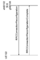
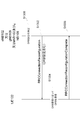
- FIG. 4 is a diagram showing an example of a flow of an RRC connection resetting procedure in each embodiment of the present invention.
- the RRC connection reconfiguration procedure includes the establishment, change, and release of RBs in E-UTRA and the change and release of secondary cells as described in Non-Patent Document 4, as well as handover and measurement ( Is a procedure used for RB etc., but may be used for RB establishment, change and release in NR, and secondary cell addition, change, release, handover and measurement, etc. It may be described in Non-Patent Document 10.
- the procedure used for establishing, changing, and releasing RBs in NR, and adding, changing, releasing, handover, measurement, etc. of cell groups is the RRC connection reconfiguration procedure. It may be called another name.
- the RRC connection reconfiguration procedure in each embodiment of the present invention is an RRC connection reconfiguration procedure including establishment, change, and release of RB in NR, and addition, change, release, handover, and measurement (measurement) of a cell group. There may be.
- RRC connection re-setting request message (RRC Connection Reconfiguration message) is transmitted to UE 122 (S400).
- the UE 122 that has received the RRC connection reconfiguration request message performs setting according to information (Information Element: IE) included in the RRC connection reconfiguration request message and notifies that the setting is completed.
- An RRC connection reconfiguration completion message (RRCConnectionReconfigurationComplete message) may be transmitted to the eNB 102 or the gNB 108, or both the eNB and the gNB (S402).
- the UE 122 may transmit an RRC connection reconfiguration completion message to both the eNB 102 and the gNB 108 regardless of whether the base station apparatus that transmitted the RRC connection reconfiguration request is the eNB 102 or the gNB 108.
- the UE 122 is not limited to the eNB 102 or the gNB 108, or both the eNB 102 and the gNB 108 for all or a part of other RRC (RRC connection setting means, RRC connection re-setting means, etc.).
- a completion message may be transmitted to both the eNB 102 and the gNB 108 regardless of whether the base station apparatus that transmitted the request message is the eNB 102 or the gNB 108.
- FIG. 5 is a block diagram showing a configuration of a terminal apparatus (UE) in each embodiment of the present invention. In order to avoid complicated explanation, FIG. 5 shows only main components closely related to the present invention.
- the UE 122 shown in FIG. 5 includes DRB configuration information (DRB configuration) in the receiving unit 500 that receives the RRC connection reconfiguration request message from the eNB 102, or gNB 108, or both the eNB and gNB, and the RRC connection reconfiguration request message.
- the setting unit 502 performs DRB setting according to the DRB setting.
- the UE 122 may include functions other than the receiving unit 500 and the setting unit 502.
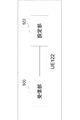
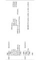
- FIG. 6 is a diagram showing an example of DRB setting reception and setting in the embodiment of the present invention.
- the eNB 102, or the gNB 108, or both the eNB 102 and the gNB 108 determine the DRB setting required for the UE 122 (S600).
- the eNB 102, or the gNB 108, or both the eNB 102 and the gNB 108 set the DRB configuration information from the core network (EPC 104, or 5GC 110, or both EPC 104 and 5 GC 110), or the capability of the UE 122 (Capability), or the information from the core network and the UE 122 You may decide based on ability.
- Information from the core network may be determined based on application service conditions such as a voice call requested by the UE 122.
- the eNB 102, or the gNB 108, or both the eNB 102 and the gNB 108 generate an RRC connection reconfiguration request (RRCConnectionReconfiguration) message including the DRB setting, and transmit the RRC connection reconfiguration request message to the UE 122 (S602).
- the receiving unit 500 of the UE 122 receives the RRC connection reconfiguration request message including the DRB setting, and passes the DRB setting to the setting unit 502.
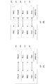
- FIG. 7 and FIG. 8 show ASN. 1 (Abstract Syntax Notation One).
- specifications related to RRC Non-Patent Document 4, Non-Patent Document 10
- DRB-ToAddMod included in the RRCConnectionReconfiguration message is the DRB setting IE.
- DRB-ToAddMod may include DRB-Identity, which is an IE of the DRB identifier, and PDCP-Config, which is PDCP entity setting information corresponding to the DRB identifier.
- PDCP-Config which is PDCP entity setting information
- PDCP-EUTRA-Config which is PDCP entity setting information for E-UTRA, or PDCP entity setting for NR.
- Information PDCP-NR-Config may be selected (CHOICE). Also, as shown in FIG. 8 of FIG. 7 and FIG.
- PDCP-EUTRA-Config and PDCP-NR-Config include pdcp-SN- which indicates the length of the PDCP sequence number (Sequence Number: SN). Size information may be included, and this pdcp-SN-Size may be an integer including seven.
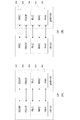
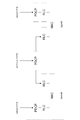
- FIG. 16, FIG. 17, and FIG. 18 show ASN. This is another example of 1 (Abstract Syntax Notation One).
- FIG.16, FIG.17 and FIG.18 is one figure. That is, FIG. 16 shows an ASN.
- FIG. 17 is a first diagram of another example of FIG. 1
- FIG. FIG. 18 is a second diagram of another example of FIG. 1, and FIG. It is the 3rd sheet in a figure showing another example of 1. 16, 17, and 18.
- 1, ⁇ abbreviation> and ⁇ abbreviation> are ASN. This indicates that other information is omitted, not a part of the notation of 1. Information may be omitted even where there is no description of ⁇ omitted> or ⁇ omitted>.
- the RRCConnectionReconfiguration message is an RRCConnectionReconfiguration-EUTRA-IE that is an IE of an RRC connection reconfiguration request for E-UTRA, or an IE of an RRC connection reconfiguration request for NR.
- a certain RRCConnectionReconfiguration-NR-IE may be selected and included.
- DRB-ToAddMod-EUTRA when the IE for the RRC connection reconfiguration request for E-UTRA is selected, the DRB that is the IE for the DRB setting for E-UTRA -ToAddMod-EUTRA may be included. Also, as shown in FIG. 17, FIG. 17, and FIG. 18, DRB-ToAddMod-EUTRA includes DRB-Identity, which is the DRB identifier IE, and PDCP for E-UTRA corresponding to the DRB identifier. PDCP-Config-EUTRA that is entity setting information may be included. Further, as shown in FIGS. 17 and 18 of FIGS.
- PDCP-Config-EUTRA which is the PDCP entity setting information for EUTRA, is further set as E-UTRA PDCP entity setting.
- PDCP-EUTRA-Config that is PDCP entity setting information for UTRA or PDCP-NR-Config that is PDCP entity setting information for NR may be selected (CHOICE).
- PDCP-EUTRA-Config and PDCP-NR-Config are pdcp indicating the length of the PDCP sequence number (Sequence Number: SN).
- -SN-Size information may be included, and this pdcp-SN-Size may be an integer including 7.
- DRB-ToAddMod-NR that is an IE for DRB setting for NR May be included.
- DRB-ToAddMod-NR includes DRB-Identity, which is the DRB identifier IE, and PDCP entity setting information for NR corresponding to the DRB identifier.
- the PDCP-Config-NR may be included.
- PDCP-Config-NR which is PDCP entity setting information for NR, is further used for E-UTRA as PDCP entity setting for NR.
- PDCP-EUTRA-Config that is PDCP entity setting information or PDCP-NR-Config that is PDCP entity setting information for NR may be selected (CHOICE). Also, as shown in FIG. 18, FIG. 17, and FIG. 18, PDCP-EUTRA-Config and PDCP-NR-Config are pdcp indicating the length of the PDCP sequence number (Sequence Number: SN). -SN-Size information may be included, and this pdcp-SN-Size may be an integer including 7.
- FIG.7, FIG.8, FIG.16, FIG.17 and FIG. 1 message name, IE name, parameter name, etc. are examples, and other names may be used.
- the E-UTRA RLC entity in FIGS. 7, 8, 16, 17, and 18, the E-UTRA RLC entity, And an RLC entity for NR may be described.
- the E-UTRA MAC entity (MACMainConfig) is used in the same manner as described for the E-UTRA PDCP entity and the NR PDCP entity. (Not shown), logicalChannelConfig, etc.), and the MAC entity for NR may be described.
- the DRB setting passed from the receiving unit 500 of the UE 122 by the setting unit 502 of the UE 122 includes at least the DRB identifier and the PDCP entity setting corresponding to the DRB identifier as the PDCP entity setting for E-UTRA, or for NR Either PDCP entity configuration is included.
- the setting unit 502 of the UE 122 establishes or re-establishes the PDCP entity according to the DRB identifier and the PDCP entity setting corresponding to the DRB identifier.
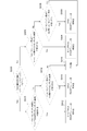
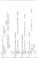
- FIG. 9 is an example of PDCP setting determination in the setting unit of the terminal device according to the embodiment of the present invention.
- the setting unit 502 of the UE 122 confirms whether or not the value of the DRB identifier exists in the current setting of the terminal device (S900). If it does not exist, it is checked whether the PDCP entity configuration corresponding to this DRB identifier includes the E-UTRA PDCP entity (S902). If included, according to the E-UTRA PDCP entity configuration information, E- A UTRA PDCP entity is established (S904).
- the PDCP entity configuration corresponding to the DRB identifier does not include the PDCP entity for E-UTRA, it is further confirmed whether the PDCP entity configuration corresponding to the DRB identifier includes the NR PDCP entity. (S906) If it is included, an NR PDCP entity is established in accordance with the NR PDCP entity setting information (S908). When the PDCP entity setting corresponding to the DRB identifier does not include the NR PDCP entity, other settings are performed (S918).
- the PDCP entity setting corresponding to the DRB identifier includes the PDCP entity for E-UTRA (S910). If so, the PDCP entity for E-UTRA is re-established according to the PDCP entity setting information for E-UTRA (S912). On the other hand, when the PDCP entity configuration corresponding to the DRB identifier does not include the PDCP entity for E-UTRA, it is further confirmed whether the PDCP entity configuration corresponding to the DRB identifier includes the NR PDCP entity.
- the NR PDCP entity is reestablished according to the NR PDCP entity setting information (S916).
- the PDCP entity setting corresponding to the DRB identifier does not include the NR PDCP entity, other settings are performed (S918).
- the PDCP entity for E-UTRA and the PDCP entity for NR may be switched.
- the PDCP entity setting corresponding to a certain DRB identifier (referred to as DRB identifier 1) in the current UE 122 setting is the PDCP entity for E-UTRA
- the DRB included in the received RRC connection reconfiguration message When the setting includes the above-described DRB identifier 1 and the PDCP entity setting corresponding to the DRB identifier 1 is the NR PDCP entity setting, the PDCP entity corresponding to the DRB identifier 1 is reset as the NR PDCP entity. .
- the DRB setting included in the received RRC connection reconfiguration message Includes the above-described DRB identifier 2 and the PDCP entity setting corresponding to this DRB identifier 2 is the PDCP entity setting for E-UTRA, the PDCP entity corresponding to DRB identifier 2 is set as the PDCP entity for E-UTRA. Reset it.
- the PDCP entity setting for E-UTRA and the PDCP entity setting for NR may be switched by the RRC connection reconfiguration message.
- the UE 122 After completing the setting in the setting unit 502 of the UE 122, in FIG. 6, the UE 122 transmits an RRC connection reconfiguration complete (RRCConnectionReconfigurationComplete) message to the eNB 102, the gNB 108, or both the eNB 102 and the gNB 108 (S606).
- RRC connection reconfiguration complete RRCConnectionReconfigurationComplete
- the DRB setting in this embodiment may be included not only in the RRC connection resetting procedure, but also in the RRC connection setting (RRC Connection Establishment) procedure and the RRC connection resetting (RRC Connection Re-Establishment) procedure.
- the PDCP entity re-establishment in the present embodiment refers to, for example, the hyperframe number (HFN) zero reset described in Non-Patent Document 5 or the header compression initial (Initialization and Refresh: IR) mode. Change to the designated encryption algorithm and algorithm, and the like.
- HFN hyperframe number
- IR header compression initial
- hyperframe numbers (Hyper Frame Number: HFN) described in non-patent literature are reset to zero, header compression is changed to the initial (Initialization and Refresh: IR) mode, specified encryption algorithm (algorithm), and encryption
- the change to the key is for E-UTRA, but may be applied for NR.
- the E-UTRA base station apparatus (eNB) or the NR base station apparatus (eNB) or the NR base station apparatus (eNB) is requested based on application service conditions such as a voice call requested by the terminal apparatus (UE).
- gNB or the eNB and gNB select whether the PDCP entity used in communication with the UE is for E-UTRA or NR, and notify the UE using the RRC connection reconfiguration message. Therefore, a PDCP entity suitable for an application service used by the UE can be established, and efficient communication can be performed with reduced protocol processing complexity.
- FIG. 10 is a diagram illustrating an example of a relationship between the radio protocol architecture on the base station apparatus side of the EN-DC and the RB in the embodiment of the present invention.
- EN-DC uses EPC as a core network, an E-UTRA base station device as a master base station (Master eNB: MeNB), and an NR base station device as a secondary base station (Secondary gNB: SgNB). Data using the radio resources of the cell groups each configured by the base station apparatus, that is, the master cell group (Master Cell Group: MCG) configured by the MeNB and the secondary cell group (Secondary Cell Group: SCG) configured by the SgNB A technique for performing communication may be used.
- the master base station is a main RRC function related to MR-DC, for example, establishment, change, and release of RBs, and addition, change, release, and handover of additional cells such as secondary cells, etc.
- the secondary base station may be a base station having a part of RRC functions such as SCG change and release.
- a part of the data to be transmitted / received is transmitted / received on the SgNB side and the rest is transmitted / received on the MeNB side.
- a node in the EPC becomes an anchor point that is a data branching / merging point
- each of the MeNB and SgNB is a bearer that is a logical path between the EPC and the bearer.
- Radio Bearer Radio Bearer: RB
- the split bearer changes the MCG bearer or SCG bearer to the split bearer by establishing the radio bearer and after establishing the MCG bearer or SCG bearer, adding the SCG side or MCG side radio bearer. There may be a method.
- the establishment and change of the MCG bearer, the SCG bearer, and the split bearer may be performed by an RRC (Radio Resource Control) connection reconfiguration procedure (Connection Reconfiguration) performed between the MeNB and the UE.
- RRC Radio Resource Control
- the cell group of the base station apparatus that becomes the anchor point of the split bearer is called an anchor cell group
- the cell group of the base station apparatus that does not become the anchor point of the split bearer is an additional cell group (additional cell). group).
- the anchor cell group may be MCG and the additional cell group may be SCG
- the anchor cell group may be SCG
- the additional cell group may be MCG.
- a split bearer when the anchor cell group is an MCG may be called an MCG split bearer
- a split bearer when the anchor cell group is an SCG may be called an SCG split bearer.
- a part of downlink data transferred from the EPC is delivered by the base station apparatus of the anchor cell group to the base station apparatus of the additional cell group, While the base station apparatus of the additional cell group transmits to the UE, the remaining data may be transmitted from the base station apparatus of the master cell group to the UE.
- the UE transmits a part of the uplink data to the base station apparatus of the additional cell group, and the base station apparatus of the additional cell group distributes a part of this uplink data to the base station apparatus of the master cell group. The UE may transmit the remaining data to the base station apparatus of the master cell group.
- PDCP PDUs may be transmitted and received between the base station apparatus of the master cell group and the base station apparatus of the additional cell group.
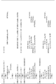
- FIG. 11 is a diagram showing an example of DRB setting reception and setting when an MCG bearer or SCG bearer is established as an anchor cell group bearer in the embodiment of the present invention. Even if it is established as an anchor cell group, the split bearer need not be changed later.
- the eNB 102 determines the DRB setting requested from the UE 122 (S1100).
- the eNB 102 may determine the DRB configuration based on information from the core network (EPC 104), or the capability (Capability) of the UE 122, or information from the core network and the capability of the UE 122.
- Information from the core network may be determined based on application service conditions such as a voice call requested by the UE 122.
- the eNB 102 generates an RRC connection reconfiguration request (RRCConnectionReconfiguration) message including DRB settings, and transmits the message to the UE 122 (S1102).
- the receiving unit 500 of the UE 122 receives the RRC connection reconfiguration request message including the DRB setting, and passes the DRB setting to the setting unit 502.
- FIG. 7 and FIG. 8 are diagrams showing the ASN. 1 (Abstract Syntax Notation One).
- DRB-ToAddMod included in the RRCConnectionReconfiguration message is an IE for DRB setting.
- DRB-ToAddMod may include DRB-Identity, which is an IE of the DRB identifier, and PDCP-Config, which is PDCP entity setting information corresponding to the DRB identifier.
- PDCP-Config which is PDCP entity setting information
- PDCP-EUTRA-Config which is PDCP entity setting information for E-UTRA
- Information PDCP-NR-Config may be selected (CHOICE).
- PDCP-EUTRA-Config and PDCP-NR-Config include pdcp-SN- which indicates the length of the PDCP sequence number (Sequence Number: SN). Size information may be included, and this pdcp-SN-Size may be an integer including seven.
- FIG. 16, FIG. 17, and FIG. 18 show the ASN. This is another example of 1 (Abstract Syntax Notation One).
- the RRCConnectionReconfiguration message is an RRCConnectionReconfiguration-EUTRA-IE that is an IE of an RRC connection reconfiguration request for E-UTRA, or an IE of an RRC connection reconfiguration request for NR.
- RRCConnectionReconfiguration-NR-IE may be selected (CHOICE).
- DRB-ToAddMod-EUTRA when the IE for the RRC connection reconfiguration request for E-UTRA is selected, the DRB that is the IE for the DRB setting for E-UTRA -ToAddMod-EUTRA may be included. Also, as shown in FIG. 17, FIG. 17, and FIG. 18, DRB-ToAddMod-EUTRA includes DRB-Identity, which is the DRB identifier IE, and PDCP for E-UTRA corresponding to the DRB identifier. PDCP-Config-EUTRA that is entity setting information may be included. Further, as shown in FIGS. 17 and 18 of FIGS.
- PDCP-Config-EUTRA which is the PDCP entity setting information for EUTRA, is further set as E-UTRA PDCP entity setting.
- PDCP-EUTRA-Config that is PDCP entity setting information for UTRA or PDCP-NR-Config that is PDCP entity setting information for NR may be selected (CHOICE).
- PDCP-EUTRA-Config and PDCP-NR-Config are pdcp indicating the length of the PDCP sequence number (Sequence Number: SN).
- -SN-Size information may be included, and this pdcp-SN-Size may be an integer including 7.
- DRB-ToAddMod-NR when IE for NR RRC connection reconfiguration request is selected, DRB-ToAddMod- NR may be included. Also, as shown in FIG. 17, FIG. 17, and FIG. 18, DRB-ToAddMod-NR includes DRB-Identity, which is the DRB identifier IE, and PDCP entity setting information for NR corresponding to the DRB identifier. The PDCP-Config-NR may be included. Further, as shown in FIGS. 17 and 18 of FIGS. 16, 17, and 18, PDCP-Config-NR, which is PDCP entity setting information for NR, is further used for E-UTRA as PDCP entity setting for NR.
- PDCP-EUTRA-Config that is PDCP entity setting information or PDCP-NR-Config that is PDCP entity setting information for NR may be selected (CHOICE). Also, as shown in FIG. 18, FIG. 17, and FIG. 18, PDCP-EUTRA-Config and PDCP-NR-Config are pdcp indicating the length of the PDCP sequence number (Sequence Number: SN). -SN-Size information may be included, and this pdcp-SN-Size may be an integer including 7.
- the ASN.1 in FIGS. 7, 8, 16, 17, and 18 is used.
- 1 message name, IE name, parameter name, etc. are examples, and other names may be used.
- the E-UTRA RLC entity in the same manner as described for the E-UTRA PDCP entity and the NR PDCP entity in FIGS. 7, 8, 16, 17, and 18, the E-UTRA RLC entity, And an RLC entity for NR may be described.
- the E-UTRA MAC entity in the same manner as described for the E-UTRA PDCP entity and the NR PDCP entity
- MACMainConfig not shown
- logicalChannelConfig etc.
- MAC entity for NR may be described.
- the DRB setting passed from the receiving unit 500 of the UE 122 by the setting unit 502 of the UE 122 includes at least the DRB identifier and the PDCP entity setting corresponding to the DRB identifier as the PDCP entity setting for E-UTRA, or for NR Either PDCP entity configuration is included.
- the setting unit 502 of the UE 122 establishes or re-establishes the PDCP entity according to the DRB identifier and the PDCP entity setting corresponding to the DRB identifier.
- FIG. 9 is an example of PDCP setting determination in the setting unit of the terminal device as described in the first embodiment. That is, the setting unit 502 of the UE 122 confirms whether or not the DRB identifier value exists in the current setting of the terminal device (S900). If it does not exist, it is checked whether the PDCP entity configuration corresponding to this DRB identifier includes the E-UTRA PDCP entity (S902). If included, according to the E-UTRA PDCP entity configuration information, E- A UTRA PDCP entity is established (S904).
- the PDCP entity configuration corresponding to the DRB identifier does not include the PDCP entity for E-UTRA, it is further confirmed whether the PDCP entity configuration corresponding to the DRB identifier includes the NR PDCP entity. (S906) If it is included, an NR PDCP entity is established in accordance with the NR PDCP entity setting information (S908). When the PDCP entity setting corresponding to the DRB identifier does not include the NR PDCP entity, other settings are performed (S918).
- the PDCP entity setting corresponding to the DRB identifier includes the PDCP entity for E-UTRA (S910). If so, the PDCP entity for E-UTRA is re-established according to the PDCP entity setting information for E-UTRA (S912). On the other hand, when the PDCP entity configuration corresponding to the DRB identifier does not include the PDCP entity for E-UTRA, it is further confirmed whether the PDCP entity configuration corresponding to the DRB identifier includes the NR PDCP entity.
- the NR PDCP entity is reestablished according to the NR PDCP entity setting information (S916).
- the PDCP entity setting corresponding to the DRB identifier does not include the NR PDCP entity, other settings are performed (S918).
- the PDCP entity for E-UTRA and the PDCP entity for NR may be switched.
- the PDCP entity setting corresponding to a certain DRB identifier (referred to as DRB identifier 1) in the current UE 122 setting is the PDCP entity for E-UTRA
- the DRB included in the received RRC connection reconfiguration message When the setting includes the above-described DRB identifier 1 and the PDCP entity setting corresponding to the DRB identifier 1 is the NR PDCP entity setting, the PDCP entity corresponding to the DRB identifier 1 is reset as the NR PDCP entity. .
- the DRB setting included in the received RRC connection reconfiguration message Includes the above-described DRB identifier 2 and the PDCP entity setting corresponding to this DRB identifier 2 is the PDCP entity setting for E-UTRA, the PDCP entity corresponding to DRB identifier 2 is set as the PDCP entity for E-UTRA. Reset it.
- the PDCP entity setting for E-UTRA and the PDCP entity setting for NR may be switched by the RRC connection reconfiguration message.
- the UE 122 After completing the setting by the setting unit 502 of the UE 122, the UE 122 transmits an RRC connection reconfiguration complete (RRCConnectionReconfigurationComplete) message to the eNB 102 in FIG. 11 (S1106).
- RRC connection reconfiguration complete RRCConnectionReconfigurationComplete
- the DRB setting in this embodiment may be included not only in the RRC connection resetting procedure, but also in the RRC connection setting (RRC Connection Establishment) procedure and the RRC connection resetting (RRC Connection Re-Establishment) procedure.
- the PDCP entity re-establishment in the present embodiment refers to, for example, the hyperframe number (HFN) zero reset described in Non-Patent Document 5 or the header compression initial (Initialization and Refresh: IR) mode. Change to the designated encryption algorithm and algorithm, and the like.
- HFN hyperframe number
- IR header compression initial
- hyperframe numbers (Hyper Frame Number: HFN) described in non-patent literature are reset to zero, header compression is changed to the initial (Initialization and Refresh: IR) mode, specified encryption algorithm (algorithm), and encryption
- the change to the key is for E-UTRA, but may be applied for NR.
- FIG. 12 shows the ASN.3 related to DRB setting of an additional cell group when changing from an MCG bearer or SCG bearer to a split bearer. 1 (Abstract Syntax Notation One).
- ASN. 1, ⁇ abbreviation> and ⁇ abbreviation> are ASN. This indicates that other information is omitted, not a part of the notation of 1. Information may be omitted even where there is no description of ⁇ omitted> or ⁇ omitted>.
- ASN. An example of ANS.1 shown in FIG. 7 and FIG. 8, or FIG. 16, FIG. It may be a part of one example.
- the DRB-ToAddModADDCG-NR IE shown in FIG. 12 relates to the DRB setting of the additional cell group, and may have another name. Also, the DRB-ToAddModADDCG-NR IE shown in FIG. 12 may be a part of the higher-level IE related to the additional cell group setting.
- the eNB 102 determines the DRB setting of the anchor cell group and the DRB setting of the additional cell group that are requested to the UE 122 (S1100).
- the DRB setting of the anchor cell group need not be changed.
- the DRB setting of the anchor cell group may include a DRB identifier and entity setting information such as a PDCP entity setting to be changed corresponding thereto.
- entity setting information such as a PDCP entity setting to be changed corresponding thereto.
- only the DRB identifier may be included in the DRB setting of the anchor cell group.
- the eNB 102 may determine whether to change the DRB setting of the anchor cell group based on information from the core network (EPC 104), capability of the UE 122 (Capability), information from the core network, and capability of the UE 122. good. Information from the core network may be determined based on application service conditions such as a voice call requested by the UE 122.
- the eNB 102 generates an RRC connection reconfiguration request (RRCConnectionReconfiguration) message including the DRB setting of the anchor cell and the DRB setting of the additional cell, and transmits the RRC connection reconfiguration request message to the UE 122 (S1102).
- RRCConnectionReconfiguration RRC connection reconfiguration request
- the receiving unit 500 of the UE 122 receives the RRC connection reconfiguration request message including the DRB setting of the anchor cell and the DRB setting of the additional cell, and passes the DRB setting of the anchor cell and the DRB setting of the additional cell to the setting unit 502.
- the DRB identifier included in the DRB configuration of the anchor cell group is present in the current UE 122 configuration, and the DRB identifier included in the DRB configuration of the anchor cell group is the additional cell group
- the DRB identifier is included in the DRB configuration, that is, when the DRB identifier value of the anchor cell group and the DRB identifier value of the additional cell group are the same, and the DRB type of the additional cell group (drb-Type in FIG. 12) -NR, etc.) is split
- the determination method for changing an existing MCG bearer or SCG bearer to a split bearer is not limited to this, and another method may be used.
- the setting unit 502 of the UE 122 establishes the DRB of the additional cell group according to the DRB setting of the additional cell group, and when the PDCP entity setting corresponding to the DRB identifier exists in the DRB setting of the anchor cell group, the PDCP entity setting The PDCP entity may be reestablished according to Through the re-establishment process, the PDCP entity for E-UTRA and the PDCP entity for NR may be switched.
- the PDCP entity setting corresponding to a certain DRB identifier (referred to as DRB identifier 1) in the current UE 122 setting is the PDCP entity for E-UTRA
- the DRB included in the received RRC connection reconfiguration message When the setting includes the above-described DRB identifier 1 and the PDCP entity setting corresponding to the DRB identifier 1 is the NR PDCP entity setting, the PDCP entity corresponding to the DRB identifier 1 is reset as the NR PDCP entity. .
- the DRB setting included in the received RRC connection reconfiguration message Includes the above-described DRB identifier 2 and the PDCP entity setting corresponding to this DRB identifier 2 is the PDCP entity setting for E-UTRA, the PDCP entity corresponding to DRB identifier 2 is set as the PDCP entity for E-UTRA. Reset it.
- the PDCP entity setting for E-UTRA and the PDCP entity setting for NR may be switched by the RRC connection reconfiguration message.
- the anchor cell group communicates with the UE based on the conditions of application services such as voice calls requested by the terminal device (UE). Select whether the PDCP entity to be used in E-UTRA or NR is used, and notify the UE using an RRC connection reconfiguration message. Therefore, even in the case of EN-DC, a PDCP entity suitable for an application service used by the UE can be established, and efficient communication with reduced complexity of protocol processing can be performed.
- the UE 122 may communicate with the 5GC 110 via the gNB, may communicate with the 5GC via the eNB, and may use the MR-DC that performs both the gNB and the eNB. Communication may be performed.
- FIG. 13 is a diagram illustrating an example of DRB setting reception and setting according to the embodiment of the present invention.
- the eNB 102, or the gNB 108, or both the eNB 102 and the gNB 108 determine the DRB configuration including the SDAP entity configuration requested to the UE 122 (S1300).
- the eNB 102, or the gNB 108, or both the eNB 102 and the gNB 108 set the DRB configuration information from the core network (EPC 104, or 5GC 110, or both EPC 104 and 5 GC 110), or the capability of the UE 122 (Capability), or the information from the core network and the UE 122 You may decide based on ability.
- Information from the core network may be determined based on application service conditions such as a voice call requested by the UE 122.
- the DRB setting may include information related to SDAP such as the SDAP header length. Further, the information regarding SDAP may be included in the SDAP entity setting, or may be included in other entity settings such as the PDCP entity setting.
- the eNB 102, or the gNB 108, or both the eNB 102 and the gNB 108 generate an RRC connection reconfiguration request (RRCConnectionReconfiguration) message including the DRB setting, and transmit it to the UE 122 (S1302).
- the receiving unit 500 of the UE 122 receives the RRC connection reconfiguration request message including the DRB setting, and passes the DRB setting to the setting unit 502.
- FIG. 14 and FIG. 15 are diagrams showing ASN. 1 (Abstract Syntax Notation One). 14 and FIG. 1, ⁇ abbreviation> and ⁇ abbreviation> are ASN. This indicates that other information is omitted, not a part of the notation of 1. Information may be omitted even where there is no description of ⁇ omitted> or ⁇ omitted>.
- FIG. 14 is an example in which SDCP header length information is included in the SDCP entity settings
- FIG. 15 is an example in which the SDCP header length is included in other PDCP entity settings.
- the SDCP header length information may be information included in either the SDCP entity configuration or the PDCP entity configuration, or may be information included in both the SDCP entity configuration and the PDCP entity configuration.
- the SDAP header length may be a multiple of 8 including zero (zero: 0).
- “len0 bits”, “len8 bits”, “len16 bits”, and “len24 bits” may be 0 bits, 8 bits, 12 bits, and 24 bits, respectively.
- an SDAP header length of zero may mean that no SDAP header exists.
- the notation and name of the SDAP header length are not limited to this, and may be another notation or name.
- 14 and FIG. 1 message name, IE name, parameter name, etc. are examples, and other names may be used.
- the ASN An example of ASN.1 shown in FIG. 7 and FIG. 8 or FIG. 16, FIG. It may be a part of one example.
- the setting unit 502 of the UE 122 will be described using the example of FIG. 14, that is, an example in which there is an SDAP header length in the SDAP entity setting.
- the DRB setting passed from the receiving unit 500 of the UE 122 to the setting unit 502 of the UE 122 includes at least the DRB identifier and the SDAP entity setting corresponding to the DRB identifier. Is included.
- the setting unit 502 of the UE 122 establishes or re-establishes the SDAP entity according to the DRB identifier and the SDAP entity setting corresponding to the DRB identifier.
- an SDAP entity is established, and the DRB identifier value passed from the receiving unit 500 is If present in the configuration, the SDAP entity may be re-established. Note that when the STAP header length is zero, the SDAP entity is established, but the processing may be that there is no SDAP header, or the processing may be that the SDAP entity is not established.
- the setting unit 502 of the UE 122 will be described using the example of FIG. 15, that is, an example in the case where the SDCP header length is included in the PDCP entity setting.
- the DRB setting passed from the setting unit 502 of the UE 122 from the receiving unit 500 of the UE 122 includes at least the DRB identifier and the PDCP entity setting corresponding to the DRB identifier, and the PDCP entity setting includes the SDAP header length. Is included.
- the setting unit 502 of the UE 122 establishes or re-establishes the PDCP entity according to the DRB identifier and the PDCP entity setting corresponding to the DRB identifier.
- the PDCP entity may be re-established.
- the established or re-established PDCP entity may specify the start position of the SDAP SDU, that is, the IP packet, from the information of the SDAP header length, and may perform header compression processing.
- the PDCP entity does not include the SSAP header length in the PDCP entity configuration, and even if it is included in the SSAP entity configuration, the SCAP SDU, that is, the start position of the IP packet, from the information on the SSAP header length included in the SSAP entity configuration. And header compression processing may be performed.
- the UE 122 After the setting is completed by the setting unit 502 of the UE 122, in FIG. 13, the UE 122 transmits an RRC connection reconfiguration complete (RRCConnectionReconfigurationComplete) message to the eNB 102 or the gNB 108, or both the eNB 102 and the gNB 108 (S1306).
- RRC connection reconfiguration complete RRCConnectionReconfigurationComplete
- the DRB setting in this embodiment may be included not only in the RRC connection resetting procedure, but also in the RRC connection setting (RRC Connection Establishment) procedure and the RRC connection resetting (RRC Connection Re-Establishment) procedure.
- the PDCP entity re-establishment in the present embodiment refers to, for example, the hyperframe number (HFN) zero reset described in Non-Patent Document 5 or the header compression initial (Initialization and Refresh: IR) mode. Change to the designated encryption algorithm and algorithm, and the like.
- HFN hyperframe number
- IR header compression initial
- hyperframe numbers (Hyper Frame Number: HFN) described in non-patent literature are reset to zero, header compression is changed to the initial (Initialization and Refresh: IR) mode, specified encryption algorithm (algorithm), and encryption
- the change to the key is for E-UTRA, but may be applied for NR.
- the DRB setting in the present embodiment assumes that the core network is 5GC, but may be applied to the case where the core network is EPC.
- the E-UTRA base station apparatus (eNB) or the NR base station apparatus (eNB) or the NR base station apparatus (eNB) is requested based on application service conditions such as a voice call requested by the terminal apparatus (UE).
- gNB or the eNB and gNB are used for communication with the UE, perform the SSAP entity setting including the SDAP header length or the PDCP entity setting including the SSAP header length, and use the RRC connection reconfiguration message to the UE.
- RRC description in each embodiment of the present invention for example, a message such as an RRC connection reset request message, and ASN. 1 and the like are assumed to be RRC for NR (for example, RRC described in Non-Patent Document 9 and Non-Patent Document 10), but may be for LTE expansion, and an E-UTRA base station apparatus It may be transmitted / received to / from a terminal device compatible with MR-DC.
- each entity such as the PDCP entity in each embodiment of the present invention may be performed by an RRC connection re-establishment procedure at the time of handover.
- the security settings may be reset.
- the program that operates on the device related to the present invention may be a program that controls the central processing unit (CPU) and the like to function the computer so as to realize the functions of the above-described embodiments related to the present invention.
- the program or the information handled by the program is temporarily read into volatile memory such as Random Access Memory (RAM) during processing, or stored in nonvolatile memory such as flash memory or Hard Disk Drive (HDD).
- RAM Random Access Memory
- HDD Hard Disk Drive
- the CPU reads and corrects / writes.
- a part of the apparatus in the above-described embodiment may be realized by a computer.
- the program for realizing the control function is recorded on a computer-readable recording medium, and the program recorded on the recording medium is read into the computer system and executed.
- the “computer system” here is a computer system built in the apparatus, and includes hardware such as an operating system and peripheral devices.
- the “computer-readable recording medium” may be any of a semiconductor recording medium, an optical recording medium, a magnetic recording medium, and the like.
- Computer-readable recording medium means that a program is dynamically stored in a short time, like a communication line when transmitting a program via a network such as the Internet or a communication line such as a telephone line. It is also possible to include those that hold a program for a certain period of time, such as a volatile memory inside a computer system that becomes a server or client in that case.
- the program may be for realizing a part of the functions described above, and may be a program that can realize the functions described above in combination with a program already recorded in the computer system. .
- each functional block or various features of the apparatus used in the above-described embodiments can be implemented or executed by an electric circuit, that is, typically an integrated circuit or a plurality of integrated circuits.
- Electrical circuits designed to perform the functions described herein can be general purpose processors, digital signal processors (DSPs), application specific integrated circuits (ASICs), field programmable gate arrays (FPGAs), or others Programmable logic devices, discrete gate or transistor logic, discrete hardware components, or a combination thereof.
- a general purpose processor may be a microprocessor, but in the alternative, the processor may be any conventional processor, controller, microcontroller, or state machine.
- the general-purpose processor or each circuit described above may be configured by a digital circuit or an analog circuit.
- an integrated circuit based on the technology can be used.
- a terminal apparatus is a terminal apparatus that supports EN-DC, and includes a receiving unit that receives an RRC connection reconfiguration message from a base station apparatus, and the RRC connection reconfiguration message includes a radio bearer. If the terminal device does not set the value of the radio bearer identifier including the identifier, and the RR PDCP entity setting is included in the RRC connection reconfiguration message, the NR PDCP
- the configuration includes a setting unit for establishing a PDCP entity according to the entity setting.
- a terminal apparatus is a terminal apparatus that supports EN-DC, and includes a receiving unit that receives an RRC connection reconfiguration message from a base station apparatus, and the RRC connection reconfiguration message includes a radio bearer. And an PDCP entity setting corresponding to the radio bearer identifier, and the PDCP entity setting is either an E-UTRA PDCP entity setting or an NR PDCP entity setting, and the value of the radio bearer identifier is If the terminal device has not been set, and if the RRC connection reconfiguration message does not contain the E-UTRA PDCP entity setting, the PDCP entity is established according to the NR PDCP entity setting. It has a setting part to , It is a configuration.
- the terminal device may be configured such that, in aspect 1 or 2, the PDCP entity corresponds to the EN-DC MCG bearer.
- a base station apparatus is a base station apparatus compatible with EN-DC, and includes a generation unit that generates an RRC connection reset message and a transmission that transmits the RRC connection reset message to a terminal apparatus
- the RRC connection reconfiguration message includes a radio bearer identifier
- the RRC connection reconfiguration message including the radio bearer identifier sets the value of the radio bearer identifier to the terminal device.
- the PDCP entity is established according to the NR PDCP entity setting.
- a base station apparatus is a base station apparatus compatible with EN-DC, a generation unit that generates an RRC connection reset message, and a transmission that transmits the RRC connection reset message to a terminal apparatus
- the RRC connection reconfiguration message includes a radio bearer identifier and a PDCP entity configuration corresponding to the radio bearer identifier, and the PDCP entity configuration includes an E-UTRA PDCP entity configuration and an NR PDCP entity configuration.
- the RRC connection reconfiguration message selected from among the radio bearer identifier and the PDCP entity configuration is a case where the terminal device has not set the value of the radio bearer identifier to the terminal device.
- the RRC connector If emissions are not the include PDCP entity set for E-UTRA reconfiguration message, the following PDCP entity set for NR, to establish a PDCP entity is configured.
- the base station apparatus may be configured such that in the aspect 4 or 5, the PDCP entity corresponds to the EN-DC MCG bearer.
- a method according to aspect 7 of the present invention is a method executed by a terminal device compatible with EN-DC, which receives an RRC connection reconfiguration message from a base station device, and the RRC connection reconfiguration message is a radio bearer. If the terminal device does not set the value of the radio bearer identifier including the identifier, and the RR PDCP entity setting is included in the RRC connection reconfiguration message, the NR PDCP A method for establishing a PDCP entity according to an entity configuration.
- a method according to an aspect 8 of the present invention is a method executed by a terminal device compatible with EN-DC, which receives an RRC connection reconfiguration message from a base station device, and the RRC connection reconfiguration message is a radio bearer. And an PDCP entity setting corresponding to the radio bearer identifier, and the PDCP entity setting is either an E-UTRA PDCP entity setting or an NR PDCP entity setting, and the value of the radio bearer identifier is If the terminal device has not been set, and if the RRC connection reconfiguration message does not contain the E-UTRA PDCP entity setting, the PDCP entity is established according to the NR PDCP entity setting. Is the way to
- the method according to aspect 9 of the present invention may be the method according to aspect 7 or 8, wherein the PDCP entity corresponds to the EN-DC MCG bearer.
- a method according to aspect 10 of the present invention is a method executed by a base station apparatus corresponding to EN-DC, which generates an RRC connection reconfiguration message, transmits the RRC connection reconfiguration message to a terminal apparatus,
- the RRC connection reconfiguration message includes a radio bearer identifier, and the RRC connection reconfiguration message including the radio bearer identifier indicates that the terminal device does not set the value of the radio bearer identifier for the terminal device.
- the RR PDCP entity setting is included in the RRC connection reconfiguration message, the PDCP entity is established according to the NR PDCP entity setting.
- a method according to an aspect 11 of the present invention is a method executed by a base station apparatus corresponding to EN-DC, which generates an RRC connection reconfiguration message, transmits the RRC connection reconfiguration message to the terminal device,
- the RRC connection reconfiguration message includes a radio bearer identifier and a PDCP entity configuration corresponding to the radio bearer identifier, and the PDCP entity configuration is selected from an E-UTRA PDCP entity configuration and an NR PDCP entity configuration.
- the RRC connection reconfiguration message including the radio bearer identifier and the PDCP entity configuration is a case where the terminal device has not set the value of the radio bearer identifier to the terminal device, and RRC connection re- If there are no the E-UTRA PDCP entity for setting a constant message, the following PDCP entity set for NR, to establish a PDCP entity is a method.
- the method according to aspect 12 of the present invention may be the method according to aspect 10 or 11, wherein the PDCP entity corresponds to the EN-DC MCG bearer.
- a terminal apparatus is a terminal apparatus that communicates with a base station apparatus, the receiving unit receiving an RRC connection reconfiguration request message including DRB (Data Radio Bearer) setting from the base station apparatus, A setting unit configured to set DRB according to DRB setting, wherein the DRB setting includes a DRB identifier and a PDCP entity setting corresponding to the DRB identifier, and the value of the DRB identifier is set to a setting of a current terminal device.
- the PDCP entity configuration information includes one of the PDCP entity configuration for E-UTRA and the PDCP entity configuration for NR, and the PDCP entity configuration information includes the PDCP entity configuration for E-UTRA.
- the PDCP entity According constant information, to establish a PDCP entity, the PDCP entity configuration information, the case that contains the PDCP entity configuration information for NR, according to the PDCP entity configuration information, to establish the PDCP entity is configured.
- a terminal apparatus is a terminal apparatus that communicates with a base station apparatus, and receives a RRC connection reconfiguration request message including a DRB (Data Radio Bearer) setting from the base station apparatus, A setting unit configured to set DRB according to DRB setting, wherein the DRB setting includes a DRB identifier and a PDCP entity setting corresponding to the DRB identifier, and the value of the DRB identifier is set to a setting of a current terminal device.
- DRB Data Radio Bearer
- the PDCP entity configuration information includes one of PDCP entity configuration for E-UTRA and PDCP entity configuration for NR, and the PDCP entity configuration information includes information on the PDCP entity configuration for E-UTRA
- the PDCP entity configuration According distribution, and re-establish the PDCP entity, the PDCP entity configuration information, the case that contains the PDCP entity configuration information for NR, according to the PDCP entity configuration information, to establish the PDCP entity is configured.
- the terminal device is an MR-DC (Multi Radio Access Technology) device that corresponds to the E-UTRA (Evolved Universal Terrestrial Radio Access) and NR (New Radio Conditology Device).
- E-UTRA becomes a master cell group
- a receiving unit that receives an RRC connection reconfiguration request message including DRB (Data Radio Bearer) setting of an anchor cell group from the master base station apparatus, and DRB setting according to the DRB setting
- the DRB configuration includes a DRB identifier and a PDCP entity configuration corresponding to the DRB identifier
- the DRB identifier value does not exist in the current terminal device configuration
- the PDCP entity configuration information includes one of the PDCP entity configuration for E-UTRA and the PDCP entity configuration for NR
- the PDCP entity setting information includes the E-UTRA PDCP entity setting information
- the PDCP entity is established according to the PDCP entity setting information
- the PDCP entity setting information includes the NR PDCP entity setting information.
- the terminal device is an MR-DC (Multi Radio Access Technology) device that corresponds to the E-UTRA (Evolved Universal Terrestrial Radio Access) and NR (New Radio Connection).
- E-UTRA becomes a master cell group
- a receiving unit that receives an RRC connection reconfiguration request message including DRB (Data Radio Bearer) setting of an anchor cell group from the master base station apparatus, and DRB setting according to the DRB setting
- the DRB configuration includes a DRB identifier and a PDCP entity configuration corresponding to the DRB identifier
- the value of the DRB identifier is present in the current terminal device configuration
- the PDCP entity configuration information includes one of PDCP entity configuration for E-UTRA and PDCP entity configuration for NR, and the PDCP entity configuration
- the information includes PDCP entity configuration information for E-UTRA, re-establishes the PDCP entity according to the PDCP entity configuration information
- the PDCP entity configuration information includes the NR PDCP
- the terminal device according to aspect 17 of the present invention may be configured in the above aspect 15 or 16, wherein the anchor cell group is a master cell group.
- the terminal device according to aspect 18 of the present invention may be configured in the above aspect 15 or 16, wherein the anchor cell group is a secondary cell group.
- a terminal apparatus is an E-UTRA (Evolved Universal Terrestrial Radio Access) and NR (New Radio) MR-DC (Multi Radio Access Technology Corresponding terminal).
- E-UTRA Evolved Universal Terrestrial Radio Access
- NR New Radio
- MR-DC Multi Radio Access Technology Corresponding terminal.
- E-UTRA becomes a master cell group
- a receiving unit that receives an RRC connection reconfiguration request message including DRB (Data Radio Bearer) setting of an anchor cell group and DRB setting of an additional cell group from the master base station device;
- DRB Data Radio Bearer
- a setting unit configured to set DRB according to the DRB setting, and the DRB setting of the anchor cell group is the D of the anchor cell group.
- a BCP identifier and a PDCP entity setting corresponding to the DRB identifier of the anchor cell group, and the DRB setting of the additional cell group includes a DRB identifier of the anchor cell group and information that a DRB type is split,
- the PDCP entity of the anchor cell group is re-established according to the PDCP entity setting information included in the DRB setting of the anchor cell group corresponding to the DRB identifier of the anchor cell group.
- the terminal device according to aspect 20 of the present invention may be configured such that, in aspect 19, the anchor cell group is a master cell group, and the additional cell group is a secondary cell group.
- the terminal device according to aspect 21 of the present invention may be configured such that, in aspect 19, the anchor cell group is a secondary cell group, and the additional cell group is a master cell group.
- the terminal device is the terminal device according to any one of aspects 13 to 21, wherein the PDCP entity setting information includes information indicating a PDCP entity setting including a PDCP sequence number length, and the PDCP sequence number The length may be one or a plurality of integer values including 7.
- a terminal apparatus is a terminal apparatus that communicates with a base station apparatus, the receiving unit receiving an RRC connection reconfiguration request message including DRB (Data Radio Bearer) setting from the base station apparatus, A setting unit configured to set DRB according to DRB setting, wherein the DRB setting includes a DRB identifier and a PDCP entity setting corresponding to the DRB identifier, and the value of the DRB identifier is set to a setting of a current terminal device.
- the PDCP entity configuration information includes one of the PDCP entity configuration for E-UTRA and the PDCP entity configuration for NR, and the PDCP entity configuration information includes the PDCP entity configuration for E-UTRA.
- the PDCP entity According constant information, to establish a PDCP entity, the PDCP entity configuration information, the case that contains the PDCP entity configuration information for NR, according to the PDCP entity configuration information, establishing a PDCP entity.
- a terminal device is a terminal device that communicates with a base station device, and receives a RRC connection reconfiguration request message including a DRB (Data Radio Bearer) setting from the base station device;
- the PDCP entity setting information includes one of PDCP entity setting for E-UTRA and PDCP entity setting for NR, and the PDCP entity setting information includes the PDCP entity setting for E-UTRA.
- the PDCP entity According to the setting information, re-establish the PDCP entity, the PDCP entity configuration information, the case that contains the PDCP entity configuration information for NR, according to the PDCP entity configuration information, establishing a PDCP entity.
- the terminal device is an MR-DC (Multi Radio Access Technology) corresponding to E-UTRA (Evolved Universal Terrestrial Radio Access) and NR (New Radio Technology).
- E-UTRA Evolved Universal Terrestrial Radio Access
- NR New Radio Technology
- the value of the DRB identifier does not exist in the current terminal device configuration, and the PDCP entity configuration information includes one of the PDCP entity configuration for E-UTRA and the PDCP entity configuration for NR.
- the PDCP entity setting information includes the PDCP entity setting information for E-UTRA
- a PDCP entity is established according to the PDCP entity setting information
- the PDCP entity setting information includes the PDCP entity setting information for NR. Is included, the PDCP entity is established according to the PDCP entity configuration information.
- the terminal device is an MR-DC (Multi Radio Access Technology) corresponding to E-UTRA (Evolved Universal Terrestrial Radio Access) and NR (New Radio Access Technology).
- E-UTRA Evolved Universal Terrestrial Radio Access
- NR New Radio Access Technology
- a receiving unit that receives an RRC connection reconfiguration request message including a DRB (Data Radio Bearer) setting of an anchor cell group from the master base station device, and a DRB according to the DRB setting
- a setting unit configured to set the DRB setting, the DRB setting includes a DRB identifier and a PDCP entity setting corresponding to the DRB identifier.
- the value of the DRB identifier is present in the current terminal device configuration, and the PDCP entity configuration information includes one of the PDCP entity configuration for E-UTRA and the PDCP entity configuration for NR,
- the entity setting information includes the PDCP entity setting information for E-UTRA
- the PDCP entity is re-established according to the PDCP entity setting information
- the PDCP entity setting information includes the PDCP entity setting information for NR If so, re-establish the PDCP entity according to the PDCP entity configuration information.
- the terminal device is an MR-DC (Multi Radio Access Technology) corresponding to E-UTRA (Evolved Universal Terrestrial Radio Access) and NR (New Radio Access Technology).
- E-UTRA Evolved Universal Terrestrial Radio Access
- NR New Radio Access Technology
- a setting unit configured to set DRB according to the DRB setting, and the DRB setting of the anchor cell group A DRCP identifier corresponding to a DRB identifier of the anchor cell group, and a DRB configuration of the additional cell group includes a DRB identifier of the anchor cell group and information that a DRB type is split,
- the PDCP entity of the anchor cell group is re-established according to the PDCP entity configuration information included in the DRB configuration of the anchor cell group corresponding to the DRB identifier of the anchor cell group.
- a terminal apparatus is a terminal apparatus that communicates with a base station apparatus, and receives a RRC connection reconfiguration request message including a DRB (Data Radio Bearer) setting from the base station apparatus;
- a DRB setting according to the DRB setting wherein the DRB setting includes a DRB identifier and an SDAP entity setting corresponding to the DRB identifier, and the value of the DRB identifier is a value of a current terminal device Does not exist in the configuration
- the SSAP entity configuration includes an SSAP header length
- the SDAP header length is one or more of an integer multiple of 8 including zero, and establishes an SSAP entity according to the SSAP configuration information To do.
- a terminal apparatus is a terminal apparatus that communicates with a base station apparatus, and receives a RRC connection reconfiguration request message including a DRB (Data Radio Bearer) setting from the base station apparatus;
- a DRB setting according to the DRB setting wherein the DRB setting includes a DRB identifier and an SDAP entity setting corresponding to the DRB identifier, and the value of the DRB identifier is a value of a current terminal device Present in the configuration
- the SSAP entity configuration includes an SSAP header length
- the SDAP header length is one or more of an integer multiple of 8 including zero, and re-establishes the SSAP entity according to the SSAP configuration information .
- the present invention is not limited to the above-described embodiment.
- an example of the apparatus has been described.
- the present invention is not limited to this, and a stationary or non-movable electronic device installed indoors or outdoors, such as an AV device, a kitchen device, It can be applied to terminal devices or communication devices such as cleaning / washing equipment, air conditioning equipment, office equipment, vending machines, and other daily life equipment.
- E-UTRA 102 eNB 104 EPC 106 NR 108 gNB 110 5GC 112, 114, 116, 118, 120, 124 Interface 122 UE 200, 300 PHY 202, 302 MAC 204, 304 RLC 206, 306 PDCP 208, 308 RRC 310 SDAP 500 Receiver 502 Setting unit
Landscapes
- Engineering & Computer Science (AREA)
- Computer Networks & Wireless Communication (AREA)
- Signal Processing (AREA)
- Mobile Radio Communication Systems (AREA)
Priority Applications (6)
| Application Number | Priority Date | Filing Date | Title |
|---|---|---|---|
| CN201880038467.1A CN110771253B (zh) | 2017-06-15 | 2018-06-15 | 终端装置、基站装置、通信方法以及集成电路 |
| MX2019014966A MX2019014966A (es) | 2017-06-15 | 2018-06-15 | Aparato terminal, aparato de estacion base, metodo de comunicacion y circuito integrado. |
| US16/620,925 US11140726B2 (en) | 2017-06-15 | 2018-06-15 | Terminal apparatus, base station apparatus, communication method, and integrated circuit |
| KR1020207000444A KR102530399B1 (ko) | 2017-06-15 | 2018-06-15 | 단말 장치, 기지국 장치, 통신 방법, 및 집적 회로 |
| EP18817843.8A EP3641482B1 (en) | 2017-06-15 | 2018-06-15 | Terminal devices, base station devices and communication methods |
| SG11201912155WA SG11201912155WA (en) | 2017-06-15 | 2018-06-15 | Terminal apparatus, base station apparatus, communication method, and integrated circuit |
Applications Claiming Priority (2)
| Application Number | Priority Date | Filing Date | Title |
|---|---|---|---|
| JP2017117492A JP7093614B2 (ja) | 2017-06-15 | 2017-06-15 | 端末装置、基地局装置、通信方法、および、集積回路 |
| JP2017-117492 | 2017-06-15 |
Publications (1)
| Publication Number | Publication Date |
|---|---|
| WO2018230728A1 true WO2018230728A1 (ja) | 2018-12-20 |
Family
ID=64658639
Family Applications (1)
| Application Number | Title | Priority Date | Filing Date |
|---|---|---|---|
| PCT/JP2018/023017 WO2018230728A1 (ja) | 2017-06-15 | 2018-06-15 | 端末装置、基地局装置、通信方法、および、集積回路 |
Country Status (8)
| Country | Link |
|---|---|
| US (1) | US11140726B2 (es) |
| EP (1) | EP3641482B1 (es) |
| JP (1) | JP7093614B2 (es) |
| KR (1) | KR102530399B1 (es) |
| CN (1) | CN110771253B (es) |
| MX (1) | MX2019014966A (es) |
| SG (1) | SG11201912155WA (es) |
| WO (1) | WO2018230728A1 (es) |
Cited By (2)
| Publication number | Priority date | Publication date | Assignee | Title |
|---|---|---|---|---|
| EP3513617B1 (en) * | 2017-11-15 | 2021-07-07 | Telefonaktiebolaget LM Ericsson (publ.) | Handling of pdcp during connection re-establishment |
| WO2021159229A1 (en) * | 2020-02-10 | 2021-08-19 | Mediatek Singapore Pte. Ltd. | Methods and apparatus of multicast radio bearer establishment for nr multicast and broadcast services |
Families Citing this family (7)
| Publication number | Priority date | Publication date | Assignee | Title |
|---|---|---|---|---|
| JP2019033419A (ja) * | 2017-08-09 | 2019-02-28 | シャープ株式会社 | 端末装置、基地局装置、通信方法、および、集積回路 |
| JP7095977B2 (ja) * | 2017-11-15 | 2022-07-05 | シャープ株式会社 | 端末装置、基地局装置、および方法 |
| US10694377B2 (en) * | 2018-09-19 | 2020-06-23 | Samsung Electronics Co., Ltd. | Method and apparatus for identifying security key in next generation mobile communication system |
| US11297669B2 (en) * | 2018-11-02 | 2022-04-05 | Samsung Electronics Co., Ltd. | Method for transmitting control signaling in relay network, configuration method and device |
| US11044632B2 (en) * | 2019-05-13 | 2021-06-22 | Qualcomm Incorporated | Header compression handling during handover |
| WO2022056810A1 (en) * | 2020-09-18 | 2022-03-24 | Qualcomm Incorporated | Anchor cell selection with multi-rat dual-connectivity |
| KR20220067775A (ko) * | 2020-11-18 | 2022-05-25 | 삼성전자주식회사 | 안테나의 임피던스 매칭을 수행하는 전자 장치 및 전자 장치의 동작 방법 |
Citations (2)
| Publication number | Priority date | Publication date | Assignee | Title |
|---|---|---|---|---|
| JP2017514367A (ja) * | 2014-03-28 | 2017-06-01 | 富士通株式会社 | ベアラ管理装置、方法及び通信システム |
| JP2017117492A (ja) | 2017-03-13 | 2017-06-29 | 株式会社日立製作所 | 見守りシステム |
Family Cites Families (12)
| Publication number | Priority date | Publication date | Assignee | Title |
|---|---|---|---|---|
| US9807818B2 (en) * | 2013-08-08 | 2017-10-31 | Industrial Technology Research Institute | Method of radio bearer establishment in dual connectivity |
| CN106134240B (zh) * | 2014-03-21 | 2019-12-13 | 三星电子株式会社 | 用于在支持多个载波的移动通信系统中发送/接收信号的方法和装置 |
| EP2922326B1 (en) * | 2014-03-21 | 2018-12-19 | Sun Patent Trust | Security key derivation in dual connectivity |
| WO2016021820A1 (en) * | 2014-08-08 | 2016-02-11 | Lg Electronics Inc. | Method for processing a packet data convergence protocol re-ordering function at a user equipment in a dual connectivity system and device therefor |
| US10869344B2 (en) * | 2015-03-19 | 2020-12-15 | Acer Incorporated | Method of radio bearer transmission in dual connectivity |
| CN106304398B (zh) | 2015-05-15 | 2021-08-27 | 夏普株式会社 | 用于重配置数据承载的方法和用户设备 |
| EP3497967B1 (en) * | 2016-08-12 | 2024-02-14 | Sony Group Corporation | Communications devices, infrastructure equipment and methods |
| EP3520548B1 (en) * | 2016-09-28 | 2021-01-27 | Sony Corporation | Telecommunications apparatus and methods for handling split radio bearers |
| US10834772B2 (en) * | 2016-09-30 | 2020-11-10 | Samsung Electronics Co., Ltd. | Method and apparatus for establishing dual-connectivity to transmit data in new radio communication architecture |
| KR102324214B1 (ko) * | 2017-01-06 | 2021-11-12 | 삼성전자 주식회사 | 차세대 이동 통신 시스템에서 이중 접속의 데이터 처리를 가속화하는 방법 및 장치 |
| US11108755B2 (en) * | 2017-03-30 | 2021-08-31 | Convida Wireless, Llc | Telecommunications apparatus and methods |
| US11375427B2 (en) | 2017-06-15 | 2022-06-28 | Samsung Electronics Co., Ltd. | Method and apparatus for controlling packet transmission |
-
2017
- 2017-06-15 JP JP2017117492A patent/JP7093614B2/ja active Active
-
2018
- 2018-06-15 KR KR1020207000444A patent/KR102530399B1/ko active IP Right Grant
- 2018-06-15 EP EP18817843.8A patent/EP3641482B1/en active Active
- 2018-06-15 CN CN201880038467.1A patent/CN110771253B/zh active Active
- 2018-06-15 MX MX2019014966A patent/MX2019014966A/es unknown
- 2018-06-15 US US16/620,925 patent/US11140726B2/en active Active
- 2018-06-15 WO PCT/JP2018/023017 patent/WO2018230728A1/ja unknown
- 2018-06-15 SG SG11201912155WA patent/SG11201912155WA/en unknown
Patent Citations (2)
| Publication number | Priority date | Publication date | Assignee | Title |
|---|---|---|---|---|
| JP2017514367A (ja) * | 2014-03-28 | 2017-06-01 | 富士通株式会社 | ベアラ管理装置、方法及び通信システム |
| JP2017117492A (ja) | 2017-03-13 | 2017-06-29 | 株式会社日立製作所 | 見守りシステム |
Non-Patent Citations (4)
| Title |
|---|
| "Improvement on capturing bearer (re)configuration procedures for LTE-NR Dual Connectivity", 3GPP TSG RAN WG2 #98 R2- 1704315, 6 May 2017 (2017-05-06), XP051264369 * |
| ANONYMOUS, 3GPP TS 36. 331 V14 2.2, vol. RAN WG2, 20 April 2017 (2017-04-20), pages 1 - 721, XP051298184 * |
| ERICSSON: "RRC approach for E-UTRAN-NR Dual Connectivity", 3GPP TSG RAN WG2 #97BIS R2-1702568, 24 March 2017 (2017-03-24), XP051254009 * |
| NTT DOCOMO, INC. ET AL.: "MCG/SCG configuration for LTE-NR Dual Connectivity", 3GPP TSG RAN WG2 #98 R2-1704192, 6 May 2017 (2017-05-06), XP051264304 * |
Cited By (2)
| Publication number | Priority date | Publication date | Assignee | Title |
|---|---|---|---|---|
| EP3513617B1 (en) * | 2017-11-15 | 2021-07-07 | Telefonaktiebolaget LM Ericsson (publ.) | Handling of pdcp during connection re-establishment |
| WO2021159229A1 (en) * | 2020-02-10 | 2021-08-19 | Mediatek Singapore Pte. Ltd. | Methods and apparatus of multicast radio bearer establishment for nr multicast and broadcast services |
Also Published As
| Publication number | Publication date |
|---|---|
| KR102530399B1 (ko) | 2023-05-09 |
| CN110771253A (zh) | 2020-02-07 |
| MX2019014966A (es) | 2020-02-20 |
| US11140726B2 (en) | 2021-10-05 |
| US20200163130A1 (en) | 2020-05-21 |
| SG11201912155WA (en) | 2020-01-30 |
| EP3641482B1 (en) | 2023-08-16 |
| EP3641482A1 (en) | 2020-04-22 |
| JP2019004318A (ja) | 2019-01-10 |
| JP7093614B2 (ja) | 2022-06-30 |
| KR20200016351A (ko) | 2020-02-14 |
| CN110771253B (zh) | 2023-10-31 |
| EP3641482A4 (en) | 2020-11-18 |
Similar Documents
| Publication | Publication Date | Title |
|---|---|---|
| WO2018230728A1 (ja) | 端末装置、基地局装置、通信方法、および、集積回路 | |
| WO2018230727A1 (ja) | 端末装置、基地局装置、通信方法、および、集積回路 | |
| KR102567297B1 (ko) | 단말 장치, 기지국 장치, 통신 방법, 및, 집적 회로 | |
| JP7145611B2 (ja) | 端末装置、方法、および、集積回路 | |
| JP2023176001A (ja) | 端末装置、通信方法、および基地局装置 | |
| WO2020091047A1 (ja) | 端末装置、基地局装置、および方法 | |
| JP7267701B2 (ja) | 端末装置、基地局装置、方法、および、集積回路 | |
| WO2020031934A1 (ja) | 端末装置、基地局装置、および方法 | |
| JP7271766B2 (ja) | 端末装置、基地局装置、通信方法、および、集積回路 | |
| JP7518306B2 (ja) | 端末装置、基地局装置、および方法 | |
| WO2020091048A1 (ja) | 端末装置、および、方法 | |
| JP2022185122A (ja) | 端末装置、基地局装置、および方法 | |
| JP2022118227A (ja) | 端末装置、基地局装置、および方法 |
Legal Events
| Date | Code | Title | Description |
|---|---|---|---|
| 121 | Ep: the epo has been informed by wipo that ep was designated in this application |
Ref document number: 18817843 Country of ref document: EP Kind code of ref document: A1 |
|
| NENP | Non-entry into the national phase |
Ref country code: DE |
|
| ENP | Entry into the national phase |
Ref document number: 20207000444 Country of ref document: KR Kind code of ref document: A |
|
| ENP | Entry into the national phase |
Ref document number: 2018817843 Country of ref document: EP Effective date: 20200115 |