WO2018216456A1 - Optical unit - Google Patents
Optical unit Download PDFInfo
- Publication number
- WO2018216456A1 WO2018216456A1 PCT/JP2018/017711 JP2018017711W WO2018216456A1 WO 2018216456 A1 WO2018216456 A1 WO 2018216456A1 JP 2018017711 W JP2018017711 W JP 2018017711W WO 2018216456 A1 WO2018216456 A1 WO 2018216456A1
- Authority
- WO
- WIPO (PCT)
- Prior art keywords
- light source
- light
- optical unit
- reflector
- rotating
- Prior art date
Links
Images


Classifications
-
- F—MECHANICAL ENGINEERING; LIGHTING; HEATING; WEAPONS; BLASTING
- F21—LIGHTING
- F21S—NON-PORTABLE LIGHTING DEVICES; SYSTEMS THEREOF; VEHICLE LIGHTING DEVICES SPECIALLY ADAPTED FOR VEHICLE EXTERIORS
- F21S41/00—Illuminating devices specially adapted for vehicle exteriors, e.g. headlamps
- F21S41/60—Illuminating devices specially adapted for vehicle exteriors, e.g. headlamps characterised by a variable light distribution
- F21S41/65—Illuminating devices specially adapted for vehicle exteriors, e.g. headlamps characterised by a variable light distribution by acting on light sources
- F21S41/663—Illuminating devices specially adapted for vehicle exteriors, e.g. headlamps characterised by a variable light distribution by acting on light sources by switching light sources
-
- F—MECHANICAL ENGINEERING; LIGHTING; HEATING; WEAPONS; BLASTING
- F21—LIGHTING
- F21S—NON-PORTABLE LIGHTING DEVICES; SYSTEMS THEREOF; VEHICLE LIGHTING DEVICES SPECIALLY ADAPTED FOR VEHICLE EXTERIORS
- F21S41/00—Illuminating devices specially adapted for vehicle exteriors, e.g. headlamps
- F21S41/30—Illuminating devices specially adapted for vehicle exteriors, e.g. headlamps characterised by reflectors
- F21S41/32—Optical layout thereof
- F21S41/33—Multi-surface reflectors, e.g. reflectors with facets or reflectors with portions of different curvature
-
- F—MECHANICAL ENGINEERING; LIGHTING; HEATING; WEAPONS; BLASTING
- F21—LIGHTING
- F21S—NON-PORTABLE LIGHTING DEVICES; SYSTEMS THEREOF; VEHICLE LIGHTING DEVICES SPECIALLY ADAPTED FOR VEHICLE EXTERIORS
- F21S41/00—Illuminating devices specially adapted for vehicle exteriors, e.g. headlamps
- F21S41/10—Illuminating devices specially adapted for vehicle exteriors, e.g. headlamps characterised by the light source
- F21S41/14—Illuminating devices specially adapted for vehicle exteriors, e.g. headlamps characterised by the light source characterised by the type of light source
- F21S41/141—Light emitting diodes [LED]
- F21S41/143—Light emitting diodes [LED] the main emission direction of the LED being parallel to the optical axis of the illuminating device
- F21S41/145—Light emitting diodes [LED] the main emission direction of the LED being parallel to the optical axis of the illuminating device the main emission direction of the LED being opposite to the main emission direction of the illuminating device
-
- F—MECHANICAL ENGINEERING; LIGHTING; HEATING; WEAPONS; BLASTING
- F21—LIGHTING
- F21S—NON-PORTABLE LIGHTING DEVICES; SYSTEMS THEREOF; VEHICLE LIGHTING DEVICES SPECIALLY ADAPTED FOR VEHICLE EXTERIORS
- F21S41/00—Illuminating devices specially adapted for vehicle exteriors, e.g. headlamps
- F21S41/60—Illuminating devices specially adapted for vehicle exteriors, e.g. headlamps characterised by a variable light distribution
- F21S41/67—Illuminating devices specially adapted for vehicle exteriors, e.g. headlamps characterised by a variable light distribution by acting on reflectors
- F21S41/675—Illuminating devices specially adapted for vehicle exteriors, e.g. headlamps characterised by a variable light distribution by acting on reflectors by moving reflectors
-
- F—MECHANICAL ENGINEERING; LIGHTING; HEATING; WEAPONS; BLASTING
- F21—LIGHTING
- F21V—FUNCTIONAL FEATURES OR DETAILS OF LIGHTING DEVICES OR SYSTEMS THEREOF; STRUCTURAL COMBINATIONS OF LIGHTING DEVICES WITH OTHER ARTICLES, NOT OTHERWISE PROVIDED FOR
- F21V14/00—Controlling the distribution of the light emitted by adjustment of elements
- F21V14/04—Controlling the distribution of the light emitted by adjustment of elements by movement of reflectors
-
- F—MECHANICAL ENGINEERING; LIGHTING; HEATING; WEAPONS; BLASTING
- F21—LIGHTING
- F21V—FUNCTIONAL FEATURES OR DETAILS OF LIGHTING DEVICES OR SYSTEMS THEREOF; STRUCTURAL COMBINATIONS OF LIGHTING DEVICES WITH OTHER ARTICLES, NOT OTHERWISE PROVIDED FOR
- F21V7/00—Reflectors for light sources
- F21V7/04—Optical design
Definitions
- the present invention relates to an optical unit.
- the width direction of the entire optical unit tends to be large. Therefore, even if such an optical unit is to be employed in a vehicle headlamp, it may be difficult due to design restrictions.
- the present invention has been made in view of such a situation, and one of exemplary purposes thereof is to provide an optical unit having a novel arrangement of configurations.
- an optical unit is an optical unit used in a vehicular lamp, and the optical unit has a rotation axis while reflecting a light source and light emitted from the light source.
- a rotating reflector that rotates about the center.
- the rotary reflector is arranged so that the rotation axis of the rotary reflector intersects the horizontal plane.
- the light source can be arranged above or below the rotation axis of the rotary reflector.
- a projection lens that projects the light emitted from the light source and reflected by the rotating reflector in the light irradiation direction of the optical unit may be further provided.
- the light source may be disposed between the rotating reflector and the projection lens in the front-rear direction of the vehicle and below the rotation axis of the rotating reflector. Thereby, the length of the optical unit in the vehicle front-rear direction can be suppressed.
- the light source may include a first light source including one or more first light emitting elements and a second light source including one or more second light emitting elements.
- the rotating reflector reflects light emitted from the first light source at one of the right and left regions of the rotating reflector, and reflects light emitted from the second light source at the other region on the right and left sides of the rotating reflector. May be. Thereby, the light radiate
- a substrate on which the first light source and the second light source are mounted may be further provided. Thereby, the number of parts and the number of manufacturing steps can be reduced.
- the projection lens includes a first projection unit that receives light emitted from the first light source and reflected by the rotary reflector, and a second projection unit that receives light emitted from the second light source and reflected by the rotary reflector. You may have. Thereby, a plurality of light distribution patterns can be formed.
- a light shielding portion is provided on the incident surface side of the projection lens.
- the light shielding portion prevents the light emitted from the first light source and reflected by the rotary reflector from entering the second projection portion, and the second light emitting portion.
- the second light source is turned off, it is possible to suppress the light emitted from the first light source from passing through the second projection unit as stray light and generating glare.
- the 1st light source is light-extinguished, it can suppress that the light radiate
- the first projection unit may have a rear focal length L1 that is longer than the rear focal length L2 of the second projection unit.
- the rotation axis of the rotating reflector may be inclined toward the first projection unit with respect to the longitudinal direction of the vehicle.
- the rotating reflector may include a rotating part and a plurality of blades functioning as reflecting surfaces provided around the rotating part.
- the rotating reflector may be provided with a reflecting surface so that light from the light source reflected while rotating forms a light distribution pattern.
- FIG. 5A is a schematic diagram for explaining a light source image in a state where the blade of the rotary reflector is rotated by 20 ° with respect to the reference position
- FIG. 5B is a diagram showing the blade of the rotary reflector with respect to the reference position.
- the optical unit according to this embodiment can be used for various lamps. Below, the case where the optical unit which concerns on this Embodiment is applied to the vehicle headlamp among lamps is demonstrated.
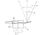
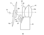
- FIG. 1 is a top view schematically showing a schematic configuration of the vehicle headlamp according to the first embodiment.
- FIG. 2 is a side view schematically showing a schematic configuration of the vehicle headlamp according to the first embodiment.
- illustration of some components such as a lamp body, a cover, and an extension, which are components of a vehicle headlamp, is omitted.
- the vehicle headlamp 10 includes an optical unit 12.
- the optical unit 12 includes a light source 14 and a rotating reflector 16 that rotates about the rotation axis R while reflecting light emitted from the light source 14.
- the rotary reflector 16 is arranged so that the rotation axis R of the rotary reflector intersects the horizontal plane H.
- the horizontal plane H is not only physically defined as a plane that intersects with the earth's gravity at right angles, but for example, an optical axis and a central axis of a projection lens (a straight line passing through the center of the projection lens) described later. And a plane parallel to the reference plane P on which the vehicle headlamp 10 is placed.
- a plane including the optical axes of the left and right vehicle headlamps may be a horizontal plane H.
- the case where the rotation axis R intersects the horizontal plane H includes a case where a line extending the rotation axis R intersects the horizontal plane H.
- the light source 14 has four light emitting elements 14a arranged in a line along the vehicle width direction W.
- a semiconductor light emitting element such as an LED, an EL element, or an LD element is used.
- the light emitting element 14 a is mounted on one element mounting substrate 15.
- the element mounting substrate 15 is fixed to the surface of the heat sink 17.
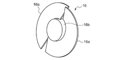
- FIG. 3 is a side view schematically showing the configuration of the rotary reflector according to the first embodiment.
- FIG. 4 is a top view schematically showing the configuration of the rotary reflector according to the first embodiment.
- the rotating reflector 16 is rotated in one direction around the rotation axis R by a driving source such as a motor.
- the rotating reflector 16 is provided with a blade 16a as a reflecting surface so as to form a desired light distribution pattern by scanning the light of each light source reflected while rotating. That is, the rotating reflector 16 emits visible light from the light emitting unit as an irradiation beam by the rotation operation, and forms a desired light distribution pattern by scanning the irradiation beam.
- the rotating reflector 16 is provided with two blades 16a having the same shape and functioning as a reflecting surface around the cylindrical rotating portion 16b.
- the rotation axis R of the rotary reflector 16 is inclined with respect to the horizontal plane H.
- the rotation axis R is provided so as to intersect the scanning plane S of the light (irradiation beam) of each light source that scans in the left-right direction by rotation.
- the scanning plane can be regarded as a fan-shaped plane formed by, for example, continuously connecting the light trajectories of each light source that is scanning light.
- This scanning plane S may be regarded as the horizontal plane H described above.
- the shape of the blade 16a of the rotary reflector 16 is twisted so that the angle formed by the optical axis Ax and the reflecting surface changes as it goes in the circumferential direction around the rotation axis R. As a result, as shown in FIG. 4, scanning using the light from the light source 14 becomes possible.
- the optical unit 12 can arrange the light source 14 below the rotation axis R of the rotary reflector 16 as shown in FIG.
- the light source 14 can be disposed above the rotational axis R of the rotary reflector 16 by turning the optical unit 12 upside down.
- the optical unit 12 also includes a projection lens 18 that projects the light emitted from the light source 14 and reflected by the rotary reflector 16 in the light irradiation direction (front F) of the optical unit 12.
- the light source 14 is disposed between the rotary reflector 16 and the projection lens 18 in the longitudinal direction of the vehicle (the direction along the optical axis Ax) and below the optical path L of light reflected by the rotary reflector 16 (or the rotary reflector 16). (Below the rotation axis). Thereby, the length of the optical unit 12 in the vehicle front-rear direction can be suppressed.
- the optical unit 12 includes a condensing lens 20 as a primary optical system (optical member) that changes the optical path of the light emitted from the light source 14 and directs it toward the blade 16a of the rotary reflector 16. Prepare.
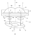
- FIG. 5A is a schematic diagram for explaining a light source image in a state in which the blade 16a of the rotary reflector 16 is rotated by 20 ° with respect to the reference position
- FIG. 5B is a diagram illustrating the blade 16a of the rotary reflector 16 as a reference. It is a schematic diagram for demonstrating the light source image of the state rotated 160 degrees with respect to the position.
- the secondary light source (light source virtual image) 19 of the light source 14 is on the opposite side of the light source 14 with the blade 16a interposed therebetween. Then, light is emitted from the secondary light source 19 and is reversely projected to form a pattern P1 including a light source image in front. Thereafter, as shown in FIG. 5B, the blade 16a of the rotary reflector 16 rotates to a position of 160 ° with respect to the reference position. The secondary light source (light source virtual image) 19 of the light source 14 at this position is as shown in FIG. Then, light is emitted from the secondary light source 19 and is reversely projected to form a pattern P1 including a light source image in front.
- the rotary reflector 16 has a plurality of blades 16a that function as reflective surfaces.
- the rotating reflector 16 is provided with a reflecting surface so that light from the light source reflected while rotating forms a light distribution pattern.
- FIG. 6 is a top view showing a schematic configuration of the vehicle headlamp according to the second embodiment.
- the side view which shows schematic structure of the vehicle headlamp which concerns on 2nd Embodiment is as substantially the same as FIG. 2, illustration is abbreviate
- the vehicle headlamp 30 includes an optical unit 32.
- the optical unit 32 includes a first light source 34 including four light emitting elements 34a and a second light source 36 including three light emitting elements 36a.
- the rotating reflector 16 reflects the light emitted from the first light source 34 in the region R1 on the right side of the rotating reflector, and reflects the light emitted from the second light source 36 in the region R2 on the left side of the rotating reflector 16. Thereby, the light emitted from the two light sources can be reflected by the single rotating reflector 16.
- the optical unit 32 further includes a common element mounting substrate 38 on which the first light source 34 and the second light source 36 are mounted. Thereby, the number of substrates can be reduced and the number of manufacturing steps can be reduced.
- the element mounting substrate 38 is fixed to the surface of the heat sink 39.
- the optical unit 32 has a projection lens 40.
- the projection lens 40 receives the first projection unit 40a on which the light emitted from the first light source 34 and reflected by the rotary reflector 16 enters, and the light emitted from the second light source 36 and reflected by the rotary reflector 16 enters.
- a second projection unit 40b a second projection unit 40b.
- the projection lens 40 is composed of one component, and the first projection unit 40a and the second projection unit 40b are integrally provided. Thereby, the number of lenses can be reduced. Further, one light distribution pattern obtained by combining a plurality of light distribution patterns can be formed by one optical unit.
- the optical unit 32 is a collection as a primary optical system (optical member) that changes the optical path of the light emitted from the first light source 34 and directs it to the region R1 on the right side of the rotary reflector 16.
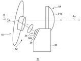
- FIG. 7 is a top view schematically showing a schematic configuration of the vehicle headlamp according to the third embodiment.
- FIG. 8 is a side view schematically showing a schematic configuration of the vehicle headlamp according to the third embodiment. Note that the same components as those in the second embodiment are denoted by the same reference numerals, and description thereof is omitted as appropriate.
- the vehicle headlamp 50 includes an optical unit 52.
- the optical unit 52 has a projection lens 54.
- the first projection unit 54a of the projection lens 54 has a rear focal length L1 (principal point) that is longer than the rear focal length L2 (distance between the principal point H ′ and the rear focal point F ′) of the second projection unit 54b. H and the distance between the rear focal point F).
- the rotation reflector 16 is inclined such that the rotation axis R of the rotation reflector is directed toward the first projection unit 54a with respect to the longitudinal direction of the vehicle (the direction along the optical axis Ax).
- the light emitted from the first projection unit 54a is more easily collected than the light emitted from the second projection unit 54b.
- the light emitted from the second projection unit 54b is more easily diffused than the light emitted from the first projection unit 54a.
- the light that has passed through the first projection unit 54a has a relatively narrow scanning area, so that the luminous intensity is increased.
- the light that has passed through the second projection unit 54b has a relatively large scanning area, and therefore the light intensity is reduced.
- the light distribution pattern formed by the light that has passed through the first projection unit 54a is suitable for a high beam light distribution pattern, for example, because the light intensity is high although the irradiation range is narrow.
- the light distribution pattern formed by the light that has passed through the second projection unit 54b is suitable for a low beam light distribution pattern, for example, because the irradiation range is wide although the luminous intensity is low.
- FIG. 9 is a top view schematically showing a schematic configuration of the vehicle headlamp according to the fourth embodiment.
- FIG. 10 is a side view schematically showing a schematic configuration of the vehicle headlamp according to the fourth embodiment.
- symbol is attached
- the vehicle headlamp 60 includes an optical unit 62.
- the optical unit 62 includes a projection lens 46 having two convex lens portions on the incident side and one convex lens portion on the exit side.
- a light shielding portion 64 is provided on the incident surface 46 c side of the projection lens 46.
- the light shielding unit 64 prevents the light emitted from the first light source 34 and reflected by the rotary reflector 16 from entering the second projection unit 46 b, and is emitted from the second light source 36 and reflected by the rotary reflector 16. Is arranged so as to prevent the incident light from entering the first projection unit 46a.
- the light shielding portion 64 is a plate-like member, and is a surface including the boundary 46d between the first projection portion 46a and the second projection portion 46b of the projection lens 46, and is disposed behind the boundary 46d.
- the second light source 36 is turned off, it is possible to suppress the light emitted from the first light source 34 from passing through the second projection unit 46b as stray light and generating glare.
- the 1st light source 34 is light-extinguished, it can suppress that the light radiate
- the angle ⁇ (see FIG. 2) formed by the rotation axis R of the rotary reflector 16 and the horizontal plane H (see FIG. 2) is, for example, in the range of 1 to 45 °, preferably in the range of 3 to 30 °, more preferably in the range of 5 to 20 °. is there.
- the diameter of the rotating reflector 16 is, for example, in the range of 30 to 100 mm, preferably in the range of 40 to 80 mm, and more preferably in the range of 50 to 70 mm.
- the width of the projection lens (in the vehicle width direction) is, for example, in the range of 50 to 120 mm, preferably in the range of 60 to 100 mm, and more preferably in the range of 70 to 90 mm.
- the height of the projection lens (vehicle height direction) is, for example, 20 to 60 mm, preferably 25 to 50 mm, and more preferably 25 to 35 mm.
- the incident angle ⁇ (see FIG. 2) at which the light emitted from the light source enters the blade 16a of the rotating reflector is less than 45 °, preferably 30 ° or less, more preferably 20 ° or less. Thereby, the incident efficiency to the projection lens of the light beam reflected by the rotating reflector is improved.
- the present invention has been described with reference to the above-described embodiments.
- the present invention is not limited to the above-described embodiments, and the configurations of the embodiments are appropriately combined or replaced. Those are also included in the present invention. Further, it is possible to appropriately change the combination and processing order in each embodiment based on the knowledge of those skilled in the art and to add various modifications such as various design changes to each embodiment. Embodiments to which is added can also be included in the scope of the present invention.
- vehicle headlamps 12 optical units, 14 light sources, 14a light emitting elements, 15 element mounting substrates, 16 rotating reflectors, 16a blades, 16b rotating parts, 18 projection lenses, 30 vehicle headlamps, 32 optical units, 34 1st light source, 34a light emitting element, 36 2nd light source, 36a light emitting element, 38 element mounting substrate, 40 projection lens, 40a 1st projection part, 40b 2nd projection part, 40c incident surface, 64 light shielding Department.
- the present invention can be used for a vehicular lamp.
Abstract
Description
図1は、第1の実施の形態に係る車両用前照灯の概略構成を模式的に示す上面図である。図2は、第1の実施の形態に係る車両用前照灯の概略構成を模式的に示す側面図である。なお、以下の各図では、車両用前照灯の構成であるランプボディ、カバー、エクステンション等の一部の部品の図示を省略している。 [First Embodiment]
FIG. 1 is a top view schematically showing a schematic configuration of the vehicle headlamp according to the first embodiment. FIG. 2 is a side view schematically showing a schematic configuration of the vehicle headlamp according to the first embodiment. In the following drawings, illustration of some components such as a lamp body, a cover, and an extension, which are components of a vehicle headlamp, is omitted.
図6は、第2の実施の形態に係る車両用前照灯の概略構成を示す上面図である。なお、第2の実施の形態に係る車両用前照灯の概略構成を示す側面図は、図2とほぼ同じであるため、図示を省略する。 [Second Embodiment]
FIG. 6 is a top view showing a schematic configuration of the vehicle headlamp according to the second embodiment. In addition, since the side view which shows schematic structure of the vehicle headlamp which concerns on 2nd Embodiment is as substantially the same as FIG. 2, illustration is abbreviate | omitted.
図7は、第3の実施の形態に係る車両用前照灯の概略構成を模式的に示す上面図である。図8は、第3の実施の形態に係る車両用前照灯の概略構成を模式的に示す側面図である。なお、第2の実施の形態と同様の構成については同じ符号を付して説明を適宜省略する。 [Third Embodiment]
FIG. 7 is a top view schematically showing a schematic configuration of the vehicle headlamp according to the third embodiment. FIG. 8 is a side view schematically showing a schematic configuration of the vehicle headlamp according to the third embodiment. Note that the same components as those in the second embodiment are denoted by the same reference numerals, and description thereof is omitted as appropriate.
図9は、第4の実施の形態に係る車両用前照灯の概略構成を模式的に示す上面図である。図10は、第4の実施の形態に係る車両用前照灯の概略構成を模式的に示す側面図である。なお、上述の各実施の形態と同様の構成については同じ符号を付して説明を適宜省略する。 [Fourth Embodiment]
FIG. 9 is a top view schematically showing a schematic configuration of the vehicle headlamp according to the fourth embodiment. FIG. 10 is a side view schematically showing a schematic configuration of the vehicle headlamp according to the fourth embodiment. In addition, about the structure similar to each above-mentioned embodiment, the same code | symbol is attached | subjected and description is abbreviate | omitted suitably.
次に、光学ユニットの各構成の諸元の範囲について例示する。回転リフレクタ16の回転軸Rと水平面Hとの成す角α(図2参照)は、例えば、1~45°の範囲、好ましくは3~30°の範囲、より好ましくは5~20°の範囲である。回転リフレクタ16の直径は、例えば、30~100mmの範囲、好ましくは40~80mmの範囲、より好ましくは、50~70mmの範囲である。 (Modification)
Next, the range of specifications of each component of the optical unit will be exemplified. The angle α (see FIG. 2) formed by the rotation axis R of the
Claims (9)
- 車両用灯具に用いられる光学ユニットであって、
前記光学ユニットは、
光源と、
前記光源から出射された光を反射しながら回転軸を中心に回転する回転リフレクタと、を備え、
前記回転リフレクタは、該回転リフレクタの回転軸が水平面と交差するように配置されていることを特徴とする光学ユニット。 An optical unit used in a vehicle lamp,
The optical unit is
A light source;
A rotating reflector that rotates about a rotation axis while reflecting light emitted from the light source, and
The optical unit, wherein the rotary reflector is arranged so that a rotation axis of the rotary reflector intersects a horizontal plane. - 前記光源から出射し、前記回転リフレクタで反射された光を光学ユニットの光照射方向に投影する投影レンズを更に備え、
前記光源は、車両の前後方向において前記回転リフレクタと前記投影レンズとの間、かつ、前記回転リフレクタの回転軸よりも下方に配置されていることを特徴とする請求項1に記載の光学ユニット。 A projection lens that projects the light emitted from the light source and reflected by the rotating reflector in the light irradiation direction of the optical unit;
2. The optical unit according to claim 1, wherein the light source is disposed between the rotary reflector and the projection lens in a front-rear direction of the vehicle and below a rotation axis of the rotary reflector. - 前記光源は、一つ以上の第1の発光素子を含む第1の光源と、一つ以上の第2の発光素子を含む第2の光源と、を有し、
前記回転リフレクタは、前記第1の光源から出射した光を該回転リフレクタの右側または左側の一方の領域で反射し、前記第2の光源から出射した光を該回転リフレクタの右側または左側の他方の領域で反射することを特徴とする請求項2に記載の光学ユニット。 The light source includes a first light source including one or more first light emitting elements, and a second light source including one or more second light emitting elements,
The rotating reflector reflects light emitted from the first light source at one of the right and left sides of the rotating reflector, and reflects light emitted from the second light source to the other of the right and left sides of the rotating reflector. The optical unit according to claim 2, wherein the optical unit reflects in a region. - 前記第1の光源および前記第2の光源を搭載する基板を更に備えることを特徴とする請求項3に記載の光学ユニット。 The optical unit according to claim 3, further comprising a substrate on which the first light source and the second light source are mounted.
- 前記投影レンズは、前記第1の光源から出射し前記回転リフレクタで反射された光が入射する第1の投影部と、前記第2の光源から出射し前記回転リフレクタで反射された光が入射する第2の投影部と、を有することを特徴とする請求項3または4に記載の光学ユニット。 The projection lens includes a first projection unit on which light emitted from the first light source and reflected by the rotary reflector enters, and light emitted from the second light source and reflected by the rotary reflector enters. The optical unit according to claim 3, further comprising a second projection unit.
- 前記光源は、一つ以上の第1の発光素子を含む第1の光源と、一つ以上の第2の発光素子を含む第2の光源と、を有し、
前記回転リフレクタは、前記第1の光源から出射した光を該回転リフレクタの右側または左側の一方の領域で反射し、前記第2の光源から出射した光を該回転リフレクタの右側または左側の他方の領域で反射することを特徴とする請求項1に記載の光学ユニット。 The light source includes a first light source including one or more first light emitting elements, and a second light source including one or more second light emitting elements,
The rotating reflector reflects light emitted from the first light source at one of the right and left sides of the rotating reflector, and reflects light emitted from the second light source to the other of the right and left sides of the rotating reflector. The optical unit according to claim 1, wherein the optical unit reflects in a region. - 前記投影レンズの入射面側に遮光部が設けられており、
前記遮光部は、前記第1の光源から出射し前記回転リフレクタで反射された光が前記第2の投影部に入射することを妨げると共に、前記第2の光源から出射し前記回転リフレクタで反射された光が前記第1の投影部に入射することを妨げるように配置されていることを特徴とする請求項5に記載の光学ユニット。 A light-shielding portion is provided on the incident surface side of the projection lens;
The light-shielding unit prevents light emitted from the first light source and reflected by the rotary reflector from entering the second projection unit, and is emitted from the second light source and reflected by the rotary reflector. The optical unit according to claim 5, wherein the optical unit is disposed so as to prevent incident light from entering the first projection unit. - 前記第1の投影部は、前記第2の投影部の後側焦点距離L2よりも長い後側焦点距離L1を有し、
前記回転リフレクタは、該回転リフレクタの回転軸が車両の前後方向に対して前記第1の投影部に向かって傾いていることを特徴とする請求項5または7に記載の光学ユニット。 The first projection unit has a rear focal length L1 that is longer than the rear focal length L2 of the second projection unit;
8. The optical unit according to claim 5, wherein the rotary reflector is configured such that a rotation axis of the rotary reflector is inclined toward the first projection unit with respect to a front-rear direction of the vehicle. - 前記回転リフレクタは、
回転部と、
前記回転部の周囲に設けられた、反射面として機能する複数のブレードと、を有し、
回転しながら反射した光源の光が配光パターンを形成するよう反射面が設けられていることを特徴とする請求項1乃至8のいずれか1項に記載の光学ユニット。 The rotating reflector is
A rotating part;
A plurality of blades functioning as reflective surfaces provided around the rotating unit;
9. The optical unit according to claim 1, wherein a reflection surface is provided so that light of the light source reflected while rotating forms a light distribution pattern.
Priority Applications (4)
| Application Number | Priority Date | Filing Date | Title |
|---|---|---|---|
| CN201880031684.8A CN110621930A (en) | 2017-05-26 | 2018-05-08 | Optical unit |
| EP18805800.2A EP3633264B1 (en) | 2017-05-26 | 2018-05-08 | Optical unit |
| JP2019519545A JP7009465B2 (en) | 2017-05-26 | 2018-05-08 | Optical unit |
| US16/689,153 US11353188B2 (en) | 2017-05-26 | 2019-11-20 | Optical unit |
Applications Claiming Priority (2)
| Application Number | Priority Date | Filing Date | Title |
|---|---|---|---|
| JP2017104920 | 2017-05-26 | ||
| JP2017-104920 | 2017-05-26 |
Related Child Applications (1)
| Application Number | Title | Priority Date | Filing Date |
|---|---|---|---|
| US16/689,153 Continuation US11353188B2 (en) | 2017-05-26 | 2019-11-20 | Optical unit |
Publications (1)
| Publication Number | Publication Date |
|---|---|
| WO2018216456A1 true WO2018216456A1 (en) | 2018-11-29 |
Family
ID=64395654
Family Applications (1)
| Application Number | Title | Priority Date | Filing Date |
|---|---|---|---|
| PCT/JP2018/017711 WO2018216456A1 (en) | 2017-05-26 | 2018-05-08 | Optical unit |
Country Status (5)
| Country | Link |
|---|---|
| US (1) | US11353188B2 (en) |
| EP (1) | EP3633264B1 (en) |
| JP (1) | JP7009465B2 (en) |
| CN (1) | CN110621930A (en) |
| WO (1) | WO2018216456A1 (en) |
Cited By (1)
| Publication number | Priority date | Publication date | Assignee | Title |
|---|---|---|---|---|
| WO2022210913A1 (en) * | 2021-03-30 | 2022-10-06 | 株式会社小糸製作所 | Lamp unit |
Citations (5)
| Publication number | Priority date | Publication date | Assignee | Title |
|---|---|---|---|---|
| WO2011129105A1 (en) | 2010-04-13 | 2011-10-20 | 株式会社小糸製作所 | Optical unit, vehicle monitor, and obstruction detector |
| WO2015122304A1 (en) * | 2014-02-13 | 2015-08-20 | 株式会社小糸製作所 | Optical unit and vehicular lighting |
| JP2016075722A (en) * | 2014-10-02 | 2016-05-12 | 大日本印刷株式会社 | Illumination device, optical module and projection device |
| WO2016204139A1 (en) * | 2015-06-16 | 2016-12-22 | 三菱電機株式会社 | Headlight device and lighting device |
| JP2017037806A (en) * | 2015-08-11 | 2017-02-16 | 株式会社小糸製作所 | Road surface drawing lighting fixture unit |
Family Cites Families (8)
| Publication number | Priority date | Publication date | Assignee | Title |
|---|---|---|---|---|
| JP5702216B2 (en) * | 2011-04-22 | 2015-04-15 | 株式会社小糸製作所 | Optical unit |
| JP5698065B2 (en) * | 2011-04-22 | 2015-04-08 | 株式会社小糸製作所 | Obstacle detection device |
| JP6176988B2 (en) | 2013-04-22 | 2017-08-09 | 株式会社小糸製作所 | Vehicle lighting |
| JP6162497B2 (en) * | 2013-06-21 | 2017-07-12 | 株式会社小糸製作所 | Lamp unit and vehicle lamp |
| JP6264709B2 (en) * | 2013-12-25 | 2018-01-24 | スタンレー電気株式会社 | Vehicle lighting |
| JP6274891B2 (en) * | 2014-02-03 | 2018-02-07 | 株式会社小糸製作所 | Vehicle lighting |
| JP6455710B2 (en) * | 2015-01-22 | 2019-01-23 | スタンレー電気株式会社 | Vehicle lighting |
| CN105465715A (en) * | 2015-12-23 | 2016-04-06 | 江西省绿野汽车照明有限公司 | Head lamp for high and low-beam light car |
-
2018
- 2018-05-08 JP JP2019519545A patent/JP7009465B2/en active Active
- 2018-05-08 EP EP18805800.2A patent/EP3633264B1/en active Active
- 2018-05-08 WO PCT/JP2018/017711 patent/WO2018216456A1/en active Application Filing
- 2018-05-08 CN CN201880031684.8A patent/CN110621930A/en active Pending
-
2019
- 2019-11-20 US US16/689,153 patent/US11353188B2/en active Active
Patent Citations (5)
| Publication number | Priority date | Publication date | Assignee | Title |
|---|---|---|---|---|
| WO2011129105A1 (en) | 2010-04-13 | 2011-10-20 | 株式会社小糸製作所 | Optical unit, vehicle monitor, and obstruction detector |
| WO2015122304A1 (en) * | 2014-02-13 | 2015-08-20 | 株式会社小糸製作所 | Optical unit and vehicular lighting |
| JP2016075722A (en) * | 2014-10-02 | 2016-05-12 | 大日本印刷株式会社 | Illumination device, optical module and projection device |
| WO2016204139A1 (en) * | 2015-06-16 | 2016-12-22 | 三菱電機株式会社 | Headlight device and lighting device |
| JP2017037806A (en) * | 2015-08-11 | 2017-02-16 | 株式会社小糸製作所 | Road surface drawing lighting fixture unit |
Non-Patent Citations (1)
| Title |
|---|
| See also references of EP3633264A4 |
Cited By (1)
| Publication number | Priority date | Publication date | Assignee | Title |
|---|---|---|---|---|
| WO2022210913A1 (en) * | 2021-03-30 | 2022-10-06 | 株式会社小糸製作所 | Lamp unit |
Also Published As
| Publication number | Publication date |
|---|---|
| US11353188B2 (en) | 2022-06-07 |
| CN110621930A (en) | 2019-12-27 |
| EP3633264B1 (en) | 2023-01-18 |
| JP7009465B2 (en) | 2022-02-10 |
| EP3633264A4 (en) | 2021-02-17 |
| JPWO2018216456A1 (en) | 2020-03-26 |
| US20200080702A1 (en) | 2020-03-12 |
| EP3633264A1 (en) | 2020-04-08 |
Similar Documents
| Publication | Publication Date | Title |
|---|---|---|
| CN108375029B (en) | Optical unit | |
| US20050162857A1 (en) | Lamp unit for vehicle and illumination lamp for vehicle | |
| JP6691806B2 (en) | Vehicle lighting | |
| JP6271181B2 (en) | Vehicle lighting | |
| JP5666882B2 (en) | High beam lamp unit | |
| JP6690960B2 (en) | Vehicle lighting | |
| WO2015122304A1 (en) | Optical unit and vehicular lighting | |
| WO2020137636A1 (en) | Optical unit | |
| JP2016110760A (en) | Lighting fixture unit | |
| JP6935185B2 (en) | Vehicle headlights | |
| JP6556530B2 (en) | Vehicle lighting | |
| JP7009097B2 (en) | Optical unit | |
| JP5763475B2 (en) | Lighting fixtures for vehicles | |
| JP5381351B2 (en) | Vehicle lighting | |
| JP7001487B2 (en) | Vehicle lighting | |
| WO2018216456A1 (en) | Optical unit | |
| CN111076138B (en) | Vehicle lamp and rotating reflector | |
| JP2007324001A (en) | Lamp for vehicle | |
| JP2017188332A (en) | Vehicular lighting fixture | |
| JP6985807B2 (en) | Optical unit | |
| JP2019021543A (en) | Vehicular lighting fixture | |
| JP7125473B2 (en) | lighting unit | |
| CN109708068B (en) | Vehicle lamp unit and vehicle lamp | |
| WO2023095530A1 (en) | Optical unit | |
| JP6872417B2 (en) | Optical unit |
Legal Events
| Date | Code | Title | Description |
|---|---|---|---|
| 121 | Ep: the epo has been informed by wipo that ep was designated in this application |
Ref document number: 18805800 Country of ref document: EP Kind code of ref document: A1 |
|
| ENP | Entry into the national phase |
Ref document number: 2019519545 Country of ref document: JP Kind code of ref document: A |
|
| NENP | Non-entry into the national phase |
Ref country code: DE |
|
| WWE | Wipo information: entry into national phase |
Ref document number: 2018805800 Country of ref document: EP |
|
| ENP | Entry into the national phase |
Ref document number: 2018805800 Country of ref document: EP Effective date: 20200102 |