WO2018216347A1 - Evaluating device, evaluating method, and evaluating program - Google Patents
Evaluating device, evaluating method, and evaluating program Download PDFInfo
- Publication number
- WO2018216347A1 WO2018216347A1 PCT/JP2018/012230 JP2018012230W WO2018216347A1 WO 2018216347 A1 WO2018216347 A1 WO 2018216347A1 JP 2018012230 W JP2018012230 W JP 2018012230W WO 2018216347 A1 WO2018216347 A1 WO 2018216347A1
- Authority
- WO
- WIPO (PCT)
- Prior art keywords
- data
- display
- evaluation
- area
- subject
- Prior art date
Links
Images


Classifications
-
- G—PHYSICS
- G16—INFORMATION AND COMMUNICATION TECHNOLOGY [ICT] SPECIALLY ADAPTED FOR SPECIFIC APPLICATION FIELDS
- G16H—HEALTHCARE INFORMATICS, i.e. INFORMATION AND COMMUNICATION TECHNOLOGY [ICT] SPECIALLY ADAPTED FOR THE HANDLING OR PROCESSING OF MEDICAL OR HEALTHCARE DATA
- G16H50/00—ICT specially adapted for medical diagnosis, medical simulation or medical data mining; ICT specially adapted for detecting, monitoring or modelling epidemics or pandemics
- G16H50/20—ICT specially adapted for medical diagnosis, medical simulation or medical data mining; ICT specially adapted for detecting, monitoring or modelling epidemics or pandemics for computer-aided diagnosis, e.g. based on medical expert systems
-
- A—HUMAN NECESSITIES
- A61—MEDICAL OR VETERINARY SCIENCE; HYGIENE
- A61B—DIAGNOSIS; SURGERY; IDENTIFICATION
- A61B10/00—Other methods or instruments for diagnosis, e.g. instruments for taking a cell sample, for biopsy, for vaccination diagnosis; Sex determination; Ovulation-period determination; Throat striking implements
-
- A—HUMAN NECESSITIES
- A61—MEDICAL OR VETERINARY SCIENCE; HYGIENE
- A61B—DIAGNOSIS; SURGERY; IDENTIFICATION
- A61B3/00—Apparatus for testing the eyes; Instruments for examining the eyes
- A61B3/10—Objective types, i.e. instruments for examining the eyes independent of the patients' perceptions or reactions
- A61B3/113—Objective types, i.e. instruments for examining the eyes independent of the patients' perceptions or reactions for determining or recording eye movement
-
- A—HUMAN NECESSITIES
- A61—MEDICAL OR VETERINARY SCIENCE; HYGIENE
- A61B—DIAGNOSIS; SURGERY; IDENTIFICATION
- A61B5/00—Measuring for diagnostic purposes; Identification of persons
- A61B5/103—Detecting, measuring or recording devices for testing the shape, pattern, colour, size or movement of the body or parts thereof, for diagnostic purposes
- A61B5/11—Measuring movement of the entire body or parts thereof, e.g. head or hand tremor, mobility of a limb
- A61B5/1126—Measuring movement of the entire body or parts thereof, e.g. head or hand tremor, mobility of a limb using a particular sensing technique
- A61B5/1128—Measuring movement of the entire body or parts thereof, e.g. head or hand tremor, mobility of a limb using a particular sensing technique using image analysis
-
- A—HUMAN NECESSITIES
- A61—MEDICAL OR VETERINARY SCIENCE; HYGIENE
- A61B—DIAGNOSIS; SURGERY; IDENTIFICATION
- A61B5/00—Measuring for diagnostic purposes; Identification of persons
- A61B5/16—Devices for psychotechnics; Testing reaction times ; Devices for evaluating the psychological state
- A61B5/163—Devices for psychotechnics; Testing reaction times ; Devices for evaluating the psychological state by tracking eye movement, gaze, or pupil change
-
- A—HUMAN NECESSITIES
- A61—MEDICAL OR VETERINARY SCIENCE; HYGIENE
- A61B—DIAGNOSIS; SURGERY; IDENTIFICATION
- A61B5/00—Measuring for diagnostic purposes; Identification of persons
- A61B5/40—Detecting, measuring or recording for evaluating the nervous system
- A61B5/4029—Detecting, measuring or recording for evaluating the nervous system for evaluating the peripheral nervous systems
- A61B5/4041—Evaluating nerves condition
-
- G—PHYSICS
- G09—EDUCATION; CRYPTOGRAPHY; DISPLAY; ADVERTISING; SEALS
- G09B—EDUCATIONAL OR DEMONSTRATION APPLIANCES; APPLIANCES FOR TEACHING, OR COMMUNICATING WITH, THE BLIND, DEAF OR MUTE; MODELS; PLANETARIA; GLOBES; MAPS; DIAGRAMS
- G09B19/00—Teaching not covered by other main groups of this subclass
-
- G—PHYSICS
- G16—INFORMATION AND COMMUNICATION TECHNOLOGY [ICT] SPECIALLY ADAPTED FOR SPECIFIC APPLICATION FIELDS
- G16H—HEALTHCARE INFORMATICS, i.e. INFORMATION AND COMMUNICATION TECHNOLOGY [ICT] SPECIALLY ADAPTED FOR THE HANDLING OR PROCESSING OF MEDICAL OR HEALTHCARE DATA
- G16H30/00—ICT specially adapted for the handling or processing of medical images
- G16H30/40—ICT specially adapted for the handling or processing of medical images for processing medical images, e.g. editing
-
- A—HUMAN NECESSITIES
- A61—MEDICAL OR VETERINARY SCIENCE; HYGIENE
- A61B—DIAGNOSIS; SURGERY; IDENTIFICATION
- A61B3/00—Apparatus for testing the eyes; Instruments for examining the eyes
- A61B3/0016—Operational features thereof
- A61B3/0025—Operational features thereof characterised by electronic signal processing, e.g. eye models
-
- A—HUMAN NECESSITIES
- A61—MEDICAL OR VETERINARY SCIENCE; HYGIENE
- A61B—DIAGNOSIS; SURGERY; IDENTIFICATION
- A61B3/00—Apparatus for testing the eyes; Instruments for examining the eyes
- A61B3/10—Objective types, i.e. instruments for examining the eyes independent of the patients' perceptions or reactions
- A61B3/11—Objective types, i.e. instruments for examining the eyes independent of the patients' perceptions or reactions for measuring interpupillary distance or diameter of pupils
- A61B3/111—Objective types, i.e. instruments for examining the eyes independent of the patients' perceptions or reactions for measuring interpupillary distance or diameter of pupils for measuring interpupillary distance
Definitions
- the present invention relates to an evaluation apparatus, an evaluation method, and an evaluation program.
- the corneal reflection method is known as one of the gaze detection techniques.
- the subject is irradiated with infrared light emitted from a light source
- the subject's eyeball irradiated with infrared light is photographed with a camera
- the pupil of the pupil against the corneal reflection image which is a reflection image of the light source on the corneal surface, is captured.
- the position is detected and the subject's line of sight is detected.
- Patent Document 1 describes a technique for examining brain function by detecting eye movement.
- the present invention has been made in view of the above, and an object of the present invention is to provide an evaluation apparatus, an evaluation method, and an evaluation program capable of performing highly accurate evaluation of a subject.
- An evaluation apparatus includes an image data acquisition unit that acquires image data of an eyeball of a subject, a gazing point detection unit that detects position data of the gazing point of the subject based on the image data, and a plurality of targets
- a display control unit that performs a display operation for displaying an object on a display screen, a non-display operation for hiding the object at a predetermined timing after the display operation is started, and a display control unit configured to display the object on the display screen.
- the gazing point exists in the corresponding area in a non-display period in which the non-display operation is performed based on an area setting unit that sets a plurality of corresponding areas corresponding to each and the position data of the gazing point
- the evaluation method includes obtaining image data of a subject's eyeball, detecting position data of the subject's gaze point based on the image data, and displaying a plurality of objects on a display screen.
- the evaluation program includes a process for acquiring image data of a subject's eyeball, a process for detecting position data of the gaze point of the subject based on the image data, and displaying a plurality of objects on a display screen.
- a display operation to be performed, a non-display operation to hide the object at a predetermined timing after the display operation is started, and a plurality of corresponding regions corresponding to each of the objects on the display screen A process for determining whether or not the gazing point exists in the corresponding area in a non-display period in which the non-display operation is performed, and determination data based on the position data of the gazing point
- a process for obtaining each region data indicating the corresponding region in which the gazing point is detected in the non-display period among the corresponding regions To execute a process of obtaining the evaluation data of the subject, to a computer.
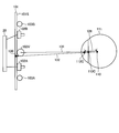
- FIG. 1 is a perspective view schematically showing an example of a visual line detection device according to the first embodiment.
- FIG. 2 is a diagram schematically illustrating a positional relationship among the display device, the stereo camera device, the illumination device, and the eyeball of the subject according to the present embodiment.
- FIG. 3 is a diagram illustrating an example of a hardware configuration of the visual line detection device according to the present embodiment.
- FIG. 4 is a functional block diagram illustrating an example of a visual line detection device according to the present embodiment.
- FIG. 5 is a schematic diagram for explaining the calculation method of the position data of the corneal curvature center according to the present embodiment.
- FIG. 6 is a schematic diagram for explaining the calculation method of the position data of the corneal curvature center according to the present embodiment.
- FIG. 5 is a schematic diagram for explaining the calculation method of the position data of the corneal curvature center according to the present embodiment.
- FIG. 7 is a flowchart illustrating an example of a gaze detection method according to the present embodiment.
- FIG. 8 is a schematic diagram for explaining an example of calibration processing according to the present embodiment.
- FIG. 9 is a flowchart showing an example of the calibration process according to the present embodiment.
- FIG. 10 is a schematic diagram for explaining an example of a gazing point detection process according to the present embodiment.
- FIG. 11 is a flowchart illustrating an example of a gazing point detection process according to the present embodiment.
- FIG. 12 is a diagram illustrating an example of an image displayed on the display device by the display control unit according to the present embodiment.
- FIG. 13 is a diagram illustrating an example of the movement of the gaze point of the subject.
- FIG. 14 is a diagram illustrating an example of an image displayed on the display device by the display control unit according to the present embodiment.
- FIG. 15 is a diagram illustrating an example of an image displayed on the display device by the display control unit according to the present embodiment.
- FIG. 16 is a diagram illustrating an example of an image displayed on the display device by the display control unit according to the present embodiment.
- FIG. 17 is a diagram illustrating an example of an image displayed on the display device by the display control unit according to the present embodiment.
- FIG. 18 is a diagram illustrating an example of an image displayed on the display device by the display control unit according to the present embodiment.
- FIG. 19 is a diagram illustrating an example of an image displayed on the display device by the display control unit according to the present embodiment.
- FIG. 15 is a diagram illustrating an example of an image displayed on the display device by the display control unit according to the present embodiment.
- FIG. 16 is a diagram illustrating an example of an image displayed on the display device by the display control unit according to the present embodiment.
- FIG. 20 is a diagram illustrating an example of an image displayed on the display device by the display control unit according to the present embodiment.
- FIG. 21 is a time chart showing the time at which each video is displayed.
- FIG. 22 is a flowchart illustrating an example of the evaluation method according to the present embodiment.
- FIG. 23 is a flowchart illustrating an example of an evaluation method according to the second embodiment.
- the direction parallel to the first axis of the predetermined surface is the X-axis direction
- the direction parallel to the second axis of the predetermined surface orthogonal to the first axis is the Y-axis direction
- a direction parallel to the third axis is taken as a Z-axis direction.
- the predetermined plane includes an XY plane.
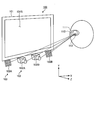
- FIG. 1 is a perspective view schematically showing an example of a visual line detection device 100 according to the present embodiment.
- the line-of-sight detection device 100 is used as an evaluation device that evaluates the subject of interest.
- the line-of-sight detection device 100 includes a display device 101, a stereo camera device 102, and an illumination device 103.
- the display device 101 includes a flat panel display such as a liquid crystal display (LCD) or an organic EL display (OLED).
- the display device 101 functions as a display unit.
- the display screen 101S of the display device 101 is substantially parallel to the XY plane.
- the X-axis direction is the left-right direction of the display screen 101S
- the Y-axis direction is the up-down direction of the display screen 101S
- the Z-axis direction is the depth direction orthogonal to the display screen 101S.
- the stereo camera device 102 includes a first camera 102A and a second camera 102B.
- the stereo camera device 102 is disposed below the display screen 101S of the display device 101.
- the first camera 102A and the second camera 102B are arranged in the X-axis direction.
- the first camera 102A is arranged in the ⁇ X direction with respect to the second camera 102B.
- Each of the first camera 102A and the second camera 102B includes an infrared camera, and includes, for example, an optical system that can transmit near-infrared light having a wavelength of 850 [nm], and an imaging device that can receive the near-infrared light. .
- the illumination device 103 includes a first light source 103A and a second light source 103B.
- the illumination device 103 is arranged below the display screen 101S of the display device 101.
- the first light source 103A and the second light source 103B are arranged in the X-axis direction.
- the first light source 103A is arranged in the ⁇ X direction with respect to the first camera 102A.
- the second light source 103B is arranged in the + X direction with respect to the second camera 102B.
- Each of the first light source 103A and the second light source 103B includes an LED (light emitting diode) light source, and can emit, for example, near-infrared light having a wavelength of 850 [nm]. Note that the first light source 103A and the second light source 103B may be disposed between the first camera 102A and the second camera 102B.
- FIG. 2 is a diagram schematically showing a positional relationship among the display device 101, the stereo camera device 102, the illumination device 103, and the eyeball 111 of the subject according to the present embodiment.
- the illumination device 103 emits near-infrared light as detection light to illuminate the eyeball 111 of the subject.
- the stereo camera device 102 captures the eyeball 111 with the second camera 102B when the detection light emitted from the first light source 103A is applied to the eyeball 111, and the detection light emitted from the second light source 103B is applied to the eyeball 111.
- the eyeball 111 is photographed by the first camera 102A.
- a frame synchronization signal is output from at least one of the first camera 102A and the second camera 102B.
- the first light source 103A and the second light source 103B emit detection light based on the frame synchronization signal.
- the first camera 102A acquires image data of the eyeball 111 when the detection light emitted from the second light source 103B is irradiated to the eyeball 111.
- the second camera 102B acquires image data of the eyeball 111 when the detection light emitted from the first light source 103A is irradiated on the eyeball 111.
- the eyeball 111 When the eyeball 111 is irradiated with detection light, a part of the detection light is reflected by the pupil 112, and light from the pupil 112 enters the stereo camera device 102.
- a cornea reflection image 113 that is a virtual image of the cornea is formed on the eyeball 111, and light from the cornea reflection image 113 enters the stereo camera device 102.
- the intensity of light incident on the stereo camera device 102 from the pupil 112 is reduced, and the cornea The intensity of light incident on the stereo camera device 102 from the reflected image 113 is increased. That is, the image of the pupil 112 acquired by the stereo camera device 102 has low brightness, and the image of the cornea reflection image 113 has high brightness.
- the stereo camera device 102 can detect the position of the pupil 112 and the position of the cornea reflection image 113 based on the luminance of the acquired image.
- FIG. 3 is a diagram illustrating an example of a hardware configuration of the visual line detection device 100 according to the present embodiment.
- the line-of-sight detection device 100 includes a display device 101, a stereo camera device 102, a lighting device 103, a computer system 20, an input / output interface device 30, a drive circuit 40, and an output device 50.
- the input device 60 and the audio output device 70 are provided.
- the computer system 20 includes an arithmetic processing device 20A and a storage device 20B.
- the computer system 20, the drive circuit 40, the output device 50, the input device 60, and the audio output device 70 perform data communication via the input / output interface device 30.
- the arithmetic processing unit 20A includes a microprocessor such as a CPU (central processing unit).
- the storage device 20B includes a memory or storage such as a ROM (read only memory) and a RAM (random access memory).
- the arithmetic processing device 20A performs arithmetic processing according to the computer program 20C stored in the storage device 20B.
- the drive circuit 40 generates a drive signal and outputs it to the display device 101, the stereo camera device 102, and the illumination device 103. Further, the drive circuit 40 supplies the image data of the eyeball 111 acquired by the stereo camera device 102 to the computer system 20 via the input / output interface device 30.
- the output device 50 includes a display device such as a flat panel display.
- the output device 50 may include a printing device.
- the input device 60 generates input data when operated.
- the input device 60 includes a keyboard or mouse for a computer system.
- the input device 60 may include a touch sensor provided on the display screen of the output device 50 that is a display device.
- the audio output device 70 includes a speaker and outputs, for example, audio for prompting the subject to pay attention.
- the display device 101 and the computer system 20 are separate devices. Note that the display device 101 and the computer system 20 may be integrated.
- the line-of-sight detection device 100 includes a tablet personal computer
- the computer system 20, the input / output interface device 30, the drive circuit 40, and the display device 101 may be mounted on the tablet personal computer.
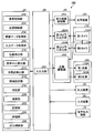
- FIG. 4 is a functional block diagram showing an example of the visual line detection device 100 according to the present embodiment.
- the input / output interface device 30 includes an input / output unit 302.
- the drive circuit 40 generates a drive signal for driving the display device 101 and outputs the drive signal to the display device 101, and generates a drive signal for driving the first camera 102A to generate the first camera.
- a first camera input / output unit 404A that outputs to the second camera 102B
- a second camera input / output unit 404B that generates a drive signal for driving the second camera 102B and outputs it to the second camera 102B, the first light source 103A and the second light source 103A.
- a light source drive unit 406 that generates a drive signal for driving the two light sources 103B and outputs the drive signals to the first light source 103A and the second light source 103B.
- the first camera input / output unit 404A supplies the image data of the eyeball 111 acquired by the first camera 102A to the computer system 20 via the input / output unit 302.
- the second camera input / output unit 404B supplies the image data of the eyeball 111 acquired by the second camera 102B to the computer system 20 via the input / output unit 302.
- the computer system 20 controls the line-of-sight detection device 100.
- the computer system 20 includes a display control unit 202, a light source control unit 204, an image data acquisition unit 206, an input data acquisition unit 208, a position detection unit 210, a curvature center calculation unit 212, and a gaze point detection unit 214.
- the functions of the computer system 20 are exhibited by the arithmetic processing device 20A and the storage device 20B.
- the display control unit 202 repeatedly performs a display operation for displaying a plurality of objects on the display screen 101S and a non-display operation for hiding the objects at a predetermined timing after the display operation is started.
- a period in which a plurality of objects are displayed by the display operation is defined as a display period, and a period in which the plurality of objects are not displayed by the non-display operation is defined as a non-display period.
- the display control unit 202 displays, for example, a video to be shown to the subject on the display screen 101S of the display device 101. This video includes a scene where a plurality of objects are displayed and a scene where the plurality of objects are not displayed.
- the display control unit 202 performs a display operation for displaying a plurality of objects on the display screen 101S and a non-display operation for hiding the plurality of objects by reproducing the video.
- video contains the scene which displays the range area
- this video includes a scene where character information or the like for instructing the subject is displayed.
- the light source control unit 204 controls the operation state of the first light source 103A and the second light source 103B by controlling the light source driving unit 406.
- the light source control unit 204 controls the first light source 103A and the second light source 103B so that the first light source 103A and the second light source 103B emit detection light at different timings.
- the image data acquisition unit 206 acquires the image data of the eyeball 111 of the subject acquired by the stereo camera device 102 including the first camera 102A and the second camera 102B from the stereo camera device 102 via the input / output unit 302.
- the input data acquisition unit 208 acquires input data generated by operating the input device 60 from the input device 60 via the input / output unit 302.
- the position detection unit 210 detects the position data of the pupil center based on the image data of the eyeball 111 acquired by the image data acquisition unit 206. Further, the position detection unit 210 detects position data of the corneal reflection center based on the image data of the eyeball 111 acquired by the image data acquisition unit 206.
- the pupil center is the center of the pupil 112.
- the cornea reflection center is the center of the cornea reflection image 113.
- the position detection unit 210 detects the position data of the pupil center and the position data of the corneal reflection center for the left and right eyeballs 111 of the subject.
- the curvature center calculation unit 212 calculates position data of the corneal curvature center of the eyeball 111 based on the image data of the eyeball 111 acquired by the image data acquisition unit 206.
- the gaze point detection unit 214 detects the position data of the gaze point of the subject based on the image data of the eyeball 111 acquired by the image data acquisition unit 206.
- the position data of the gazing point refers to position data of the intersection point between the subject's line-of-sight vector defined by the three-dimensional global coordinate system and the display screen 101S of the display device 101.
- the gazing point detection unit 214 detects the eye gaze vectors of the left and right eyeballs 111 of the subject based on the pupil center position data and the corneal curvature center position data acquired from the image data of the eyeball 111. After the gaze vector is detected, the gaze point detection unit 214 detects position data of the gaze point indicating the intersection of the gaze vector and the display screen 101S.
- the area setting unit 216 sets a corresponding area corresponding to each of a plurality of objects on the display screen 101S of the display device 101.
- the area setting unit 216 sets, as a specific area, a corresponding area corresponding to an object to be examined by a subject among a plurality of objects.
- the determination unit 218 determines whether or not the gazing point exists in the plurality of corresponding areas during the non-display period in which the non-display operation is performed based on the position data of the gazing point, and outputs the determination data.
- the determination unit 218 determines whether or not the gazing point exists in the corresponding area, for example, at regular intervals.
- the fixed time can be, for example, the period of the frame synchronization signal output from the first camera 102A and the second camera 102B (for example, every 50 [msec]).
- the calculation unit 220 Based on the determination data of the determination unit 218, the calculation unit 220 obtains area data indicating a corresponding area in which a gazing point is detected during a non-display period among a plurality of corresponding areas. In addition, based on the determination data of the determination unit 218, the calculation unit 220 calculates existence time data indicating the existence time during which the gazing point is present in a plurality of corresponding regions during the non-display period. In addition, based on the determination data of the determination unit 218, the calculation unit 220 calculates arrival time data indicating the arrival time from the start time of the non-display operation until the gazing point first reaches the specific area.
- the arithmetic unit 220 includes a management timer that manages the playback time of the video and a detection timer that detects an elapsed time after the video is displayed on the display screen 101S. Based on the detection result of the detection timer, the arithmetic unit 220 can detect which of the plurality of periods in the time chart (see periods T1 to T13 in FIG. 21) is the image displayed on the display screen 101S. It is. In addition, the calculation unit 220 counts the number of times of determination that it is determined that a gazing point exists for each corresponding region. The calculation unit 220 includes a counter that counts the number of determinations for each corresponding region. In addition, the calculation unit 220 includes a counter that counts arrival time data indicating an arrival time from the start time of the non-display operation until the gazing point first reaches the specific area.
- the evaluation unit 224 obtains the evaluation data of the subject based at least on the area data.
- the evaluation data is data indicating how much the subject stores the positions of the plurality of objects displayed on the display screen 101S in the display operation.
- the evaluation unit 224 can obtain evaluation data based on the area data and the existence time data.
- the evaluation unit 224 can also obtain evaluation data based on the area data, the existence time data, and the arrival time data. In this case, for example, the evaluation data may be obtained by weighting the existence time data rather than the arrival time data.
- the storage unit 222 stores the area data, existence time data, arrival time data, and evaluation data.
- storage part 222 is a display operation
- the output control unit 226 outputs data to at least one of the display device 101, the output device 50, and the audio output device 70.
- the output control unit 226 causes the display device 101 or the output device 50 to display the area data and time data calculated by the calculation unit 220. Further, the output control unit 226 causes the display device 101 or the output device 50 to display position data of the gazing point of the left and right eyeballs 111 of the subject. Further, the output control unit 226 displays the evaluation data output from the evaluation unit 224 on the display device 101 or the output device 50.
- the curvature center calculation unit 212 calculates position data of the corneal curvature center of the eyeball 111 based on the image data of the eyeball 111.
- FIG. 5 and 6 are schematic diagrams for explaining a method for calculating the position data of the corneal curvature center 110 according to the present embodiment.
- FIG. 5 shows an example in which the eyeball 111 is illuminated by one light source 103C.
- FIG. 6 shows an example in which the eyeball 111 is illuminated by the first light source 103A and the second light source 103B.
- the light source 103C is disposed between the first camera 102A and the second camera 102B.
- Pupil center 112 ⁇ / b> C is the center of pupil 112.
- the cornea reflection center 113 ⁇ / b> C is the center of the cornea reflection image 113.
- the pupil center 112C indicates the pupil center when the eyeball 111 is illuminated by one light source 103C.
- the corneal reflection center 113C indicates the corneal reflection center when the eyeball 111 is illuminated by one light source 103C.
- the corneal reflection center 113C exists on a straight line connecting the light source 103C and the corneal curvature center 110.
- the corneal reflection center 113C is positioned at the midpoint between the corneal surface and the corneal curvature center 110.
- the corneal curvature radius 109 is the distance between the corneal surface and the corneal curvature center 110.
- the position data of the corneal reflection center 113C is detected by the stereo camera device 102.
- the corneal curvature center 110 exists on a straight line connecting the light source 103C and the corneal reflection center 113C.
- the curvature center calculation unit 212 calculates, as position data of the corneal curvature center 110, position data that has a predetermined distance from the corneal reflection center 113C on the straight line.
- the predetermined value is a value determined in advance from, for example, a general radius of curvature of the cornea, and is stored in the storage unit 222.
- the first camera 102A and the second light source 103B, and the second camera 102B and the first light source 103A are symmetrical with respect to a straight line passing through an intermediate position between the first camera 102A and the second camera 102B. It is arranged at the position. It can be considered that the virtual light source 103V exists at an intermediate position between the first camera 102A and the second camera 102B.
- the corneal reflection center 121 indicates the corneal reflection center in an image obtained by photographing the eyeball 111 with the second camera 102B.
- a corneal reflection center 122 indicates a corneal reflection center in an image obtained by photographing the eyeball 111 with the first camera 102A.
- a corneal reflection center 124 indicates a corneal reflection center corresponding to the virtual light source 103V.
- the position data of the cornea reflection center 124 is calculated based on the position data of the cornea reflection center 121 and the position data of the cornea reflection center 122 acquired by the stereo camera device 102.
- the stereo camera device 102 detects position data of the corneal reflection center 121 and position data of the corneal reflection center 122 in the three-dimensional local coordinate system defined by the stereo camera device 102.
- camera calibration is performed in advance by a stereo calibration method, and conversion parameters for converting the three-dimensional local coordinate system of the stereo camera device 102 into a three-dimensional global coordinate system are calculated.
- the conversion parameter is stored in the storage unit 222.
- the curvature center calculation unit 212 converts the position data of the corneal reflection center 121 and the position data of the corneal reflection center 122 acquired by the stereo camera device 102 into position data in the three-dimensional global coordinate system using the conversion parameters.
- the curvature center calculation unit 212 calculates position data of the corneal reflection center 124 in the three-dimensional global coordinate system based on the position data of the corneal reflection center 121 and the position data of the corneal reflection center 122 defined in the three-dimensional global coordinate system. To do.
- the corneal curvature center 110 exists on a straight line 123 connecting the virtual light source 103V and the corneal reflection center 124.
- the curvature center calculation unit 212 calculates position data on the straight line 123 where the distance from the corneal reflection center 124 is a predetermined value as position data of the corneal curvature center 110.
- the predetermined value is a value determined in advance from, for example, a general radius of curvature of the cornea, and is stored in the storage unit 222.
- the corneal curvature center 110 is calculated by the same method as that used when there is one light source.
- the corneal curvature radius 109 is the distance between the corneal surface and the corneal curvature center 110. Accordingly, the corneal curvature radius 109 is calculated by calculating the position data of the corneal surface and the position data of the corneal curvature center 110.
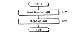
- FIG. 7 is a flowchart illustrating an example of a gaze detection method according to the present embodiment.
- calibration processing including calculation processing of position data of the corneal curvature center 110 and calculation processing of distance data between the pupil center 112C and the corneal curvature center 110, and gaze point detection processing (step S200). ) Is implemented.
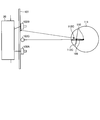
- FIG. 8 is a schematic diagram for explaining an example of calibration processing according to the present embodiment.
- the calibration process includes calculating position data of the corneal curvature center 110 and calculating a distance 126 between the pupil center 112C and the corneal curvature center 110.
- the target position 130 for making the subject gaze is set.
- the target position 130 is defined in a three-dimensional global coordinate system.
- the target position 130 is set to the center position of the display screen 101S of the display device 101, for example.
- the target position 130 may be set to the end position of the display screen 101S.
- the display control unit 202 displays the target image at the set target position 130. This makes it easier for the subject to gaze at the target position 130.
- the straight line 131 is a straight line connecting the virtual light source 103V and the corneal reflection center 113C.
- a straight line 132 is a straight line connecting the target position 130 and the pupil center 112C.
- the corneal curvature center 110 is an intersection of the straight line 131 and the straight line 132.
- the curvature center calculation unit 212 is based on the position data of the virtual light source 103V, the position data of the target position 130, the position data of the pupil center 112C, and the position data of the corneal reflection center 113C, and the position data of the corneal curvature center 110. Can be calculated.
- FIG. 9 is a flowchart showing an example of the calibration process (step S100) according to the present embodiment.
- the output control unit 226 displays the target image on the display screen 101S of the display device 101 (step S101).
- the subject can watch the target position 130 by watching the target image.
- the light source control unit 204 controls the light source driving unit 406 to emit detection light from one of the first light source 103A and the second light source 103B (step S102).
- Stereo camera apparatus 102 photographs the eyeball of the subject with the camera having the longer distance from the light source that emitted the detection light among first camera 102A and second camera 102B (step S103).
- the light source control unit 204 controls the light source driving unit 406 to emit detection light from the other light source of the first light source 103A and the second light source 103B (step S104).
- Stereo camera apparatus 102 photographs the eyeball of the subject with the camera having the longer distance from the light source that emitted the detection light among first camera 102A and second camera 102B (step S105).
- the pupil 112 is detected by the stereo camera device 102 as a dark portion, and the cornea reflection image 113 is detected by the stereo camera device 102 as a bright portion. That is, the image of the pupil 112 acquired by the stereo camera device 102 has low brightness, and the image of the cornea reflection image 113 has high brightness.
- the position detection unit 210 can detect the position data of the pupil 112 and the position data of the cornea reflection image 113 based on the luminance of the acquired image. Further, the position detection unit 210 calculates the position data of the pupil center 112 ⁇ / b> C based on the image data of the pupil 112. Further, the position detection unit 210 calculates position data of the corneal reflection center 113C based on the image data of the corneal reflection image 113 (step S106).
- the position data detected by the stereo camera device 102 is position data defined by a three-dimensional local coordinate system.
- the position detection unit 210 uses the conversion parameter stored in the storage unit 222 to perform coordinate conversion on the position data of the pupil center 112C and the position data of the corneal reflection center 113C detected by the stereo camera device 102 to obtain a third order.
- the position data of the pupil center 112C and the position data of the corneal reflection center 113C defined by the original global coordinate system are calculated (step S107).
- the curvature center calculation unit 212 calculates a straight line 131 connecting the corneal reflection center 113C defined by the global coordinate system and the virtual light source 103V (step S108).
- the curvature center calculation unit 212 calculates a straight line 132 connecting the target position 130 defined on the display screen 101S of the display device 101 and the pupil center 112C (step S109).
- the curvature center calculation unit 212 obtains an intersection between the straight line 131 calculated in step S108 and the straight line 132 calculated in step S109, and sets this intersection as the corneal curvature center 110 (step S110).
- the curvature center calculation unit 212 calculates the distance 126 between the pupil center 112C and the corneal curvature center 110, and stores it in the storage unit 222 (step S111). The stored distance is used to calculate the corneal curvature center 110 in the gazing point detection process in step S200.
- the gazing point detection process is performed after the calibration process.
- the gaze point detection unit 214 calculates the gaze vector of the subject and the position data of the gaze point based on the image data of the eyeball 111.
- FIG. 10 is a schematic diagram for explaining an example of a gazing point detection process according to the present embodiment.
- the gazing point detection process corrects the position of the corneal curvature center 110 using the distance 126 between the pupil center 112C and the corneal curvature center 110 obtained in the calibration process (step S100), and the corrected corneal curvature center. Including calculating a point of gaze using 110 position data.
- a gazing point 165 indicates a gazing point obtained from the corneal curvature center calculated using a general curvature radius value.
- the gazing point 166 indicates a gazing point obtained from the corneal curvature center calculated using the distance 126 obtained in the calibration process.
- the pupil center 112C indicates the pupil center calculated in the calibration process
- the corneal reflection center 113C indicates the corneal reflection center calculated in the calibration process.
- the straight line 173 is a straight line connecting the virtual light source 103V and the corneal reflection center 113C.
- the corneal curvature center 110 is the position of the corneal curvature center calculated from a general curvature radius value.
- the distance 126 is the distance between the pupil center 112C and the corneal curvature center 110 calculated by the calibration process.
- the corneal curvature center 110H indicates the position of the corrected corneal curvature center obtained by correcting the corneal curvature center 110 using the distance 126.
- the corneal curvature center 110H is obtained because the corneal curvature center 110 exists on the straight line 173 and the distance between the pupil center 112C and the corneal curvature center 110 is the distance 126.
- the line of sight 177 calculated when a general radius of curvature value is used is corrected to the line of sight 178.
- the gazing point on the display screen 101S of the display device 101 is corrected from the gazing point 165 to the gazing point 166.
- FIG. 11 is a flowchart illustrating an example of a gazing point detection process (step S200) according to the present embodiment. Note that the processing from step S201 to step S207 shown in FIG. 11 is the same as the processing from step S102 to step S108 shown in FIG.
- the curvature center calculation unit 212 calculates the position on the straight line 173 calculated in step S207 and the distance from the pupil center 112C equal to the distance 126 obtained by the calibration process as the corneal curvature center 110H (step S208).
- the gaze point detection unit 214 calculates a line-of-sight vector connecting the pupil center 112C and the corneal curvature center 110H (step S209).
- the line-of-sight vector indicates the line-of-sight direction that the subject is looking at.
- the gaze point detection unit 214 calculates the position data of the intersection between the line-of-sight vector and the display screen 101S of the display device 101 (step S210).
- the position data of the intersection of the line-of-sight vector and the display screen 101S of the display device 101 is the position data of the subject's point of interest on the display screen 101S defined by the three-dimensional global coordinate system.
- the gaze point detection unit 214 converts gaze point position data defined in the three-dimensional global coordinate system into position data on the display screen 101S of the display device 101 defined in the two-dimensional coordinate system (step S211). Thereby, the position data of the gazing point on the display screen 101S of the display device 101 that the subject looks at is calculated.
- the line-of-sight detection device 100 is used, for example, in an evaluation device that evaluates a subject of interest.
- the visual line detection device 100 may be referred to as an evaluation device 100 as appropriate.
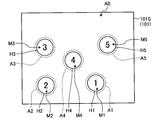
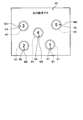
- FIG. 12 is a diagram illustrating an example of an image displayed on the display device 101 by the display control unit 202.
- the display control unit 202 displays, for example, five objects M1 to M5 on the display screen 101S of the display device 101.
- the display control unit 202 displays the objects M1 to M5, for example, on the display screen 101S in a state of being separated from each other.
- the objects M1 to M5 are images showing numbers, for example.
- the object M1 indicates “1”, the object M2 indicates “2”, the object M3 indicates “3”, the object M4 indicates “4”, and the object M5 indicates “5”. Yes.
- images showing numbers are shown as examples of the objects M1 to M5, but the present invention is not limited to this.
- images showing alphabets such as “A”, “B”, and “C”
- images showing hiragana such as “A”, “I”, “U”, “A”, “I”, “U”, etc.
- Other types of images may be used as long as they can be distinguished from each other, such as an image showing a katakana and an image showing fruits such as “apple”, “mandarin orange”, and “banana”.
- the area setting unit 216 sets the corresponding areas A1 to A5 on the display screen 101S.
- the area setting unit 216 sets the corresponding areas A1 to A5 in the areas corresponding to the objects M1 to M5, respectively.
- the region setting unit 216 sets the corresponding regions A1 to A5, for example, in a circular shape and equal dimensions, and sets the regions surrounding the objects M1 to M5.
- the corresponding regions A1 to A5 do not have to have the same shape and dimensions, and the shapes and dimensions may be different from each other.
- the corresponding regions A1 to A5 are not limited to a circular shape, and may be a polygon such as a triangle, a quadrangle, or a star, or may be another shape such as an ellipse.
- the corresponding areas A1 to A5 may have shapes along the outlines of the objects M1 to M5, respectively.
- the region setting unit 216 may set the corresponding regions A1 to A5 to portions including only a part of the objects M1 to M5, respectively.
- the display control unit 202 displays the range areas H1 to H5 on the display screen 101S of the display device 101.
- the range areas H1 to H5 are areas indicating the ranges of the corresponding areas A1 to A5.
- the range regions H1 to H5 may have the same shape as the corresponding regions A1 to A5, that is, similar shapes of the corresponding regions A1 to A5, but are not limited thereto.
- the range areas H1 to H5 are set to the ranges included in the corresponding areas A1 to A5, but are not limited thereto, and may be set outside the corresponding areas A1 to A5.
- the range areas H1 to H5 may not be displayed.
- the display control unit 202 displays an instruction to the subject in the instruction area A0 on the upper side of the display screen 101S.
- the instruction area A0 is used when instructing the subject to store the types and positions of the objects M1 to M5, or when the subject looks at a specific area that is a predetermined corresponding area among the corresponding areas A1 to A5.
- the contents of the instruction are displayed.
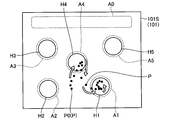
- FIG. 13 is a diagram illustrating an example of the movement of the subject's gaze point, and is a diagram illustrating an example of the gaze point displayed on the display device 101 by the output control unit 226.
- FIG. 13 shows a gazing point when the corresponding areas A1 and A4 in FIG. 12 are viewed.
- the output control unit 226 causes the display device 101 to display the plot point P indicating the position data of the subject's gaze point.
- the position data of the gazing point is detected, for example, at a period of the frame synchronization signal output from the first camera 102A and the second camera 102B (for example, every 50 [msec]).
- the first camera 102A and the second camera 102B capture images in synchronization. Therefore, the area where the plot points P are dense in the display screen 101S indicates that the subject is gazing. Moreover, it shows that the time when the subject is gazing at the region is longer as the region has a larger number of plot points P.
- FIG. 13 shows a case where the objects M1 to M5 are not displayed and the range areas H1 to H5 are displayed.
- the gazing point P first moves from the initial position P0 to the corresponding area A4 and the range area H4 (upward in FIG. 13) and enters the corresponding area A4 and the range area H4. After that, the gazing point moves inside the corresponding area A4 and the range area H4, and then comes out of the corresponding area A4 and the range area H4, toward the corresponding area A1 and the range area H1 (lower right side in FIG. 13). It moves and enters the corresponding area A1 and the range area H1.
- FIG. 13 shows a case where the objects M1 to M5 are not displayed and the range areas H1 to H5 are displayed.
- the gazing point P first moves from the initial position P0 to the corresponding area A4 and the range area H4 (upward in FIG. 13) and enters the corresponding area A4 and the range area H4. After that, the gazing point moves inside the corresponding
- the gaze point P moves the subject's line of sight. Accordingly, the corresponding area A4 and the corresponding area A1 are entered.
- cranial nerve disease and disability affect memory.
- the types and positions of the objects M1 to M5 displayed on the display screen 101S can be stored in a short period of time.
- the type and position of the objects M1 to M5 displayed on the display screen 101S cannot be memorized in a short period of time, or they are immediately forgotten even if memorized. There is.
- the subject stores the types and positions of the objects M1 to M5 in a state where the objects M1 to M5 are displayed on the display screen 101S. Thereafter, the subject is instructed not to display the objects M1 to M5 on the display screen 101S so that the viewpoint is set to one position of the objects M1 to M5.
- the subject can be evaluated by detecting which corresponding region of the corresponding regions A1 to A5 corresponding to the objects M1 to M5 is first gazeed or can be gazeed for a long time. Is possible.
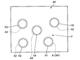
- FIG. 14 to 20 are diagrams illustrating an example of an image displayed on the display screen 101S by the display control unit 202 according to the present embodiment.
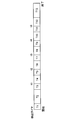
- FIG. 21 is a time chart showing the time at which each video is displayed.
- the instruction in the instruction area A0 is deleted from the display screen 101S. Accordingly, the objects M1 to M5 and the range areas H1 to H5 are displayed on the display screen 101S for a predetermined time (period T2 in FIG. 21) (display operation).
- the period T2 is a display period in which the display operation is performed. Note that the objects M1 to M5 are also displayed in the above-described period T1, and may be included in the display period. In the period T2, the remaining time may be displayed in the instruction area A0.
- the display of the objects M1 to M5 is erased from the display screen 101S. Accordingly, the display screen 101S does not display the objects M1 to M5, and the range areas H1 to H5 and the instruction “please look at the position of“ 1 ”” for a predetermined period (period T3 in FIG. 21). It is displayed on the display screen 101S.
- the instruction in the instruction area A0 is deleted from the display screen 101S. Accordingly, the range areas H1 to H5 are displayed on the display screen 101S for a predetermined period (period T4 in FIG. 21) without displaying the objects M1 to M5 (non-display operation).
- the period T4 is a non-display period during which a non-display operation is performed.
- the start time of the period T4 is the start time t1 of the non-display period (see FIG. 21). Note that the objects M1 to M5 are not displayed in the period T3, and may be included in the non-display period.
- the start time of the period T3 becomes the start time t1 of the non-display period.
- the output control unit 226 may cause the display screen 101S to display the plot point P indicating the position data of the subject's gaze point.
- the area setting unit 216 sets the corresponding area A1 corresponding to the object M1 (number “1”) as the specific area AP in the period T3 and the period T4.
- an instruction “please look at the position of“ 2 ”” is displayed on the display screen 101S. Accordingly, the range areas H1 to H5 and the instruction “please look at the position of“ 2 ”” are displayed for a predetermined time (period T5 in FIG. 21) in a state where the objects M1 to M5 are not displayed on the display screen 101S. Is displayed.
- the instruction in the instruction area A0 is deleted from the display screen 101S. Accordingly, the range areas H1 to H5 are displayed on the display screen 101S for a predetermined period (period T6 in FIG.
- the period T6 is a non-display period during which a non-display operation is performed.
- the start time of the period T6 is the start time t2 of the non-display period (see FIG. 21).
- the output control unit 226 may display the plot point P indicating the position data of the subject's gaze point on the display screen 101S.
- the area setting unit 216 sets the corresponding area A2 corresponding to the object M2 (number “2”) as the specific area AP in the period T5 and the period T6.
- the range M1 to H5 and the position of “3” are displayed on the display screen 101S in a state where the objects M1 to M5 are not displayed.
- the instruction “please stare” is displayed for a predetermined time (period T7 in FIG. 21).
- the indication in the indication area A0 is deleted from the display screen 101S, and the range areas H1 to H5 are displayed for a predetermined period (the period in FIG. 21) in a state where the objects M1 to M5 are not displayed on the display screen 101S.
- T8 Displayed (non-display operation).
- the area setting unit 216 sets the corresponding area A3 corresponding to the object M3 (number “3”) as the specific area AP in the period T7 and the period T8.
- the display screen 101S displays the range areas H1 to H5 and the instruction “please look at the position of“ 4 ”” in a state where the objects M1 to M5 are not displayed (see FIG. 21 periods T9) are displayed.
- the indication in the indication area A0 is erased from the display screen 101S, and the range areas H1 to H5 remain in the predetermined period (the period shown in FIG. 21) while the objects M1 to M5 are not displayed on the display screen 101S. T10) Displayed (non-display operation).
- the area setting unit 216 sets the corresponding area A4 corresponding to the object M4 (number “4”) as the specific area AP in the period T9 and the period T10.
- the display area 101S displays the range areas H1 to H5 and the instruction “please look at the position of“ 5 ”” in a state where the objects M1 to M5 are not displayed (see FIG. 21 periods T11) are displayed.
- the indication in the indication area A0 is deleted from the display screen 101S, and the range areas H1 to H5 are displayed for a predetermined period (the period shown in FIG. 21) while the objects M1 to M5 are not displayed on the display screen 101S.
- the area setting unit 216 sets the corresponding area A5 corresponding to the object M5 (number “5”) as the specific area AP in the period T11 and the period T12.
- the above-mentioned periods T8, T10, T12 are non-display periods in which the non-display operation is performed.
- the start times of the periods T8, T10, and T12 are the start times t3, t4, and t5 of the non-display period (see FIG. 21).
- the objects M1 to M5 are not displayed in the periods T7, T9, and T11, and may be included in the non-display period.
- the start times of the periods T7, T9, and T11 are the start times t3, t4, and t5 of the non-display period.
- the output control unit 226 may cause the display screen 101S to display the plot points P indicating the position data of the gaze point of the subject.
- the objects M1 to M5 are displayed on the display screen 101S, and an instruction such as “original number” is displayed in the instruction area A0 (FIG. 21).
- Period T13 After the period T13 has elapsed, the video playback ends. In the period T13, a message indicating that the video has ended may be displayed on the display screen 101S.
- the viewpoint can be adjusted to the correct position based on the memory.
- the subject is a cranial nerve illness / disabled person, if the user is instructed to look at one of the objects M1 to M5, the line of sight may not be aligned with the correct position.
- the determination unit 218 determines whether or not the gazing point exists in the plurality of corresponding areas A1 to A5, and outputs determination data. .
- the calculation unit 220 calculates the existence times when the plot points P indicating the gazing point exist in the corresponding areas A1 to A5 based on the determination data in the periods T4, T6, T8, T10, and T12 that are non-display periods, respectively. The indicated time data is calculated.
- the existence time includes, for example, a first existence time in which the gazing point exists in the specific area AP among the plurality of corresponding areas A1 to A5, and a second in which the gazing point exists in a corresponding area different from the specific area AP.
- the existence time data includes first existence time data indicating the first existence time and second existence time data indicating the second existence time.
- the first existence time (first existence time data) and the second existence time (second existence time data) are the sum of values obtained in the periods T4, T6, T8, T10, and T12, respectively. can do.
- the presence time data can be, for example, the number of times that the determination unit 218 determines that a gazing point exists within the non-display period for the corresponding areas A1 to A5. That is, the existence time data can be the number of plot points P detected in each of the corresponding areas A1 to A5 within the non-display period.
- the calculation unit 220 can calculate the existence time data using the count result of the counter provided in the determination unit 218.
- the evaluation unit 224 when the evaluation unit 224 obtains evaluation data based on the area data, the existence time data, and the arrival time data, for example, it can be performed as follows.
- the counter provided in the calculation unit 220 counts the first existence time data, the second existence time data, and the arrival time data.
- a counter counts based on a measurement flag.
- the measurement flag is set to a value of “0” or “1” by the calculation unit 220.
- the counter does not count arrival time data.
- the counter counts arrival time data.
- the counter value of the first existence time data is CNTA
- the counter value of the second existence time data is CNTB
- the counter value of the arrival time data is CNTC.
- the counter value CNTA and the counter value CNTB are values obtained by adding up the periods T4, T6, T8, T10, and T12.
- the counter value CNTC is a value counted every period T4, T6, T8, T10, and T12.
- the evaluation value for obtaining the evaluation data can be obtained as follows.
- the evaluation value can be obtained by determining the length of time that the subject's gazing point has been in the specific area AP.
- the time for gazing at the specific area AP becomes longer.
- the value of the counter value CNTA increases as the gazing point existing time in the specific area AP is longer. Therefore, the evaluation value can be obtained by determining whether the value of the counter value CNTA, which is the first existence time data, is equal to or greater than a predetermined value.
- the value of the counter value CNTA when the value of the counter value CNTA is equal to or greater than a predetermined value, it can be evaluated that there is a low possibility that the subject has a cranial nerve disease / disability. Further, when the value of the counter value CNTA is less than the predetermined value, it can be evaluated that the possibility that the subject is a cranial nerve disease / person with a disability is high.
- the predetermined value for example, an average value of the counter value CNTA of a subject who is not a person with cranial nerve disease / disability, or a value set based on the average value can be used. Further, as the predetermined value, for example, the lowest value of the counter value CNTA of a subject who is not a person with cranial nerve disease / disability may be used. In this case, a predetermined value may be set in advance for each age and sex, and a value corresponding to the age and sex of the subject may be used.
- the evaluation value can be obtained by the following equation (1).
- ANS1 CNTA / (CNTA + CNTB) (1)
- the value of CNTA / (CNTA + CNTB) indicates the ratio of the counter value CNTA to the sum of the counter value CNTA and the counter value CNTB. That is, the ratio of the 1st existence time when a test subject's gaze point exists in specific area AP is shown.
- ANS1 is referred to as a specific area gaze rate.
- the value of the specific area gazing rate ANS1 increases as the counter value CNTA increases. That is, the value of the specific area gaze rate ANS1 becomes a larger value as the first existence time is longer in the period T4 which is the non-display period.
- the value of the specific area gazing rate ANS1 is 1 which is the maximum value when the counter value CNTB is 0, that is, when the second existence time is 0.
- an evaluation value can be obtained by determining whether or not the specific area gazing rate ANS1 is equal to or greater than a predetermined value. For example, when the value of the specific area gaze rate ANS1 is equal to or greater than a predetermined value, it can be evaluated that the possibility that the subject has a cranial nerve disease / person with a disability is low. Moreover, when the value of the specific area gaze rate ANS1 is less than a predetermined value, it can be evaluated that the possibility that the subject is a person with a cranial nerve disease or a disability is high.
- the predetermined value for example, an average value of the specific area gazing rate ANS1 of a subject who is not a person with cranial nerve disease or a disorder, or a value set based on the average value can be used. Further, as the predetermined value, for example, the minimum value of the specific area gazing rate ANS1 of a subject who is not a person with cranial nerve disease / disability may be used. In this case, a predetermined value may be set in advance for each age and sex, and a value corresponding to the age and sex of the subject may be used.
- the evaluation value can be obtained by determining the arrival time until the subject's gazing point first reaches the specific area AP from the start time t1 of the non-display period.
- the time until the viewpoint reaches the specific area AP for the first time is shortened.
- the evaluation value can be obtained by determining whether the value of the counter value CNTC, which is arrival time data, is equal to or less than a predetermined value.
- the counter value CNTC when the counter value CNTC is equal to or greater than a predetermined value, it can be evaluated that the possibility that the subject has a cranial nerve disease / disability is low. Further, when the counter value CNTC is less than the predetermined value, it can be evaluated that there is a high possibility that the subject has a cranial nerve disease / disability.
- the evaluation value can be obtained by the following equation (2).
- the value ANS2 is a value obtained by subtracting the counter value CNTC, that is, the arrival time from the reference value K3.
- ANS2 is expressed as an arrival time evaluation value.
- K3 for example, an average value of a counter value CNTC of a subject who is not a person with cranial nerve disease or a disorder, or a value set based on the average value can be used.
- the constant K3 for example, the lowest value of the counter value CNTC of a subject who is not a person with cranial nerve disease / disability may be used.
- the constant K3 may be set in advance for each age and sex, and a value corresponding to the age and sex of the subject may be used.
- the constants K1 and K2 are constants for weighting.
- K1> K2 in the above equation (2) it is possible to obtain an evaluation value ANS that weights the influence of the specific area gaze rate ANS1 rather than the influence of the arrival time evaluation value ANS2.
- K1 ⁇ K2 in the above equation (2) an evaluation value ANS that weights the influence of the arrival time evaluation value ANS2 rather than the influence of the specific area gaze rate ANS1 can be obtained.
- the counter value CNTC may be set to a predetermined upper limit value.
- evaluation value ANS represented by the above formula (2) is longer as the value is larger, and the time until the subject's gazing point is present in the specific area AP is longer and the time until it reaches the specific area AP is shorter. Moreover, it can be evaluated that the evaluation value ANS is smaller as the value is smaller, the time during which the subject's gazing point exists in the specific area AP is shorter and the time until the subject reaches the specific area AP is longer. Therefore, evaluation data can be obtained by determining whether or not the evaluation value ANS is equal to or greater than a predetermined value.
- the evaluation value ANS when the evaluation value ANS is greater than or equal to a predetermined value, it can be evaluated that the test subject is unlikely to have a cranial nerve disease / disability. Further, when the evaluation value ANS is less than the predetermined value, it can be evaluated that there is a high possibility that the subject has a cranial nerve disease / disability.
- the output control unit 226, for example, according to the evaluation data, for example, “the subject is considered unlikely to have a cranial nerve disease / disability”
- Data character data such as “the subject is likely to have a cranial nerve disease / disability”, and the like can be output to the output device 50.
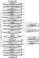
- FIG. 22 is a flowchart illustrating an example of the evaluation method according to the present embodiment.
- the display control unit 202 starts video playback (step S301).
- the images shown in FIGS. 14 to 20 are sequentially displayed on the display screen 101S.
- the arithmetic unit 220 also manages a video playback time, a detection timer that detects which category the video currently being played belongs to the period T1 to the period T13 in the time chart shown in FIG. Are reset to start measurement (step S302). Also, the determination unit 218 resets the counter values CNTA, CNTB, and CNTC to 0 and starts measurement (step S303). In addition, the arithmetic unit 220 sets the value of the measurement flag of the counter value CNTC to 0 (step S304).
- the gaze point detection unit 214 shows the video of the subject on the display screen 101S of the display device 101 at a predetermined sampling period (for example, 50 [msec]) in a state where the video displayed on the display device 101 is shown to the subject.
- Position data is detected (step S305).
- the calculation unit 220 detects which period of video from the periods T1 to T13 is displayed on the display screen 101S based on the detection result of the detection timer (step S306). S307).
- the area setting unit 216 sets a specific area AP from the plurality of corresponding areas A1 to A5 based on the detection result of the calculation unit 220 (step S308). For example, when the images of the periods T3 and T4 are displayed on the display screen 101S, the area setting unit 216 sets the corresponding area A1 as the specific area AP. When the images of the periods T5 and T6 are displayed on the display screen 101S, the area setting unit 216 sets the corresponding area A2 as the specific area AP.
- the area setting unit 216 sets the corresponding area A3 as the specific area AP.
- the area setting unit 216 sets the corresponding area A4 as the specific area AP.
- the area setting unit 216 sets the corresponding area A5 as the specific area AP.
- the arithmetic unit 220 determines whether or not the non-display operation start times t1, t2, t3, t4, and t5 have been reached based on the detection result of the management timer (step S309). ). If the calculation unit 220 determines that the start time t1, t2, t3, t4, t5 of the non-display operation has been reached (Yes in step S309), the calculation unit 220 resets the counter value CNTC of the arrival time data and measures the arrival time data. The value of the flag is set to “1” (step S310).
- the arithmetic unit 220 determines the arrival time data It is determined whether or not the value of the measurement flag is “1” (step S311).
- the calculation unit 220 determines that the value of the measurement flag of the arrival time data is “1” (Yes in step S311), the calculation unit 220 sets the counter value CNTC of the arrival time data to +1 (step S312).
- the calculation unit 220 determines that the value of the measurement flag of the arrival time data is not “1” (No in Step S311) or when the process of Step S312 is performed, the calculation unit 220 is displayed on the display screen 101S. It is determined whether or not the video is one of periods T4, T6, T8, T10, and T12 (step S313).
- the determination unit 218 specifies the gazing point. It is determined whether or not it exists in the area AP (step S314).
- the calculation unit 220 sets the counter value CNTA of the first existence time data to +1, and sets the measurement flag of the arrival time data. The value is set to “0” (step S315).
- the calculation unit 220 sets the counter value CNTB of the second existence time data to +1 (Step S316). .
- step S315 or step S316 when it is determined that the video displayed on the display screen 101S is not any of the periods T4, T6, T8, T10, and T12 (No in step S313). ), Or when position data detection fails in step S306 (No in step S306), it is determined whether or not the time at which video reproduction is completed has been reached based on the detection result of the management timer (step S317). ). When it is determined by the arithmetic unit 220 that the time for completing the video reproduction has not been reached (No in step S317), the processing from step S305 onward is repeated.
- the display control unit 202 stops the reproduction of the video (step S318).
- the evaluation unit 224 calculates an evaluation value ANS based on the area data, the existence time data, and the arrival time data obtained from the above processing result (Step S319), and sets the evaluation value ANS. Based on the evaluation data. Thereafter, the output control unit 226 outputs the evaluation data obtained by the evaluation unit 224 (step S320).
- the evaluation apparatus 100 includes the image data acquisition unit 206 that acquires the image data of the eyeball of the subject, and the gazing point detection that detects the position data of the subject's gazing point based on the image data.
- Unit 214 a display operation for displaying a plurality of objects M1 to M5 on display screen 101S, and objects M1 to M5 at predetermined timing (time t1, t2, t3, t4, t5) after the display operation is started.
- a display control unit 202 that performs a non-display operation, a region setting unit 216 that sets a plurality of corresponding regions A1 to A5 corresponding to each of the objects M1 to M5 on the display screen 101S, and a gaze point Whether or not the gazing point exists in the corresponding areas A1 to A5 during the non-display period (periods T4, T6, T8, T10, T12) in which the non-display operation is performed is determined based on the position data.
- a determination unit 218 that determines and outputs determination data, and a calculation unit that respectively obtains region data indicating the corresponding regions A1 to A5 in which the gazing point is detected during the non-display period among the corresponding regions A1 to A5 based on the determination data 220, an evaluation unit 224 that calculates the evaluation data of the subject based on the area data, and an output control unit 226 that outputs the evaluation data.
- the evaluation apparatus 100 can evaluate the memory ability of the subject based on the movement of the subject's line of sight during the non-display period. Thereby, the evaluation apparatus 100 can perform a test subject's evaluation with high precision.
- the calculation unit 220 calculates existence time data based on the existence time during which the gazing point was present in the corresponding areas A1 to A5 during the non-display period based on the determination data, and the evaluation The unit 224 obtains evaluation data based on the area data and the existence time data. Therefore, since the kind of data used when calculating
- the existence time data indicates the first existence time in which the gazing point exists in the specific area AP that is the predetermined corresponding area among the corresponding areas A1 to A5 during the non-display period.
- 1 existence time data and second existence time data indicating the second existence time in the corresponding areas A1 to A5 where the gazing point is different from the specific area AP in the non-display period.
- the display control unit 202 repeatedly performs the display operation and the non-display operation a plurality of times, and the calculation unit 220 adds the periods T4, T6, T8, T10, and T12. First existence time data and second existence time data are calculated. Thereby, in the case where the non-display operation is performed a plurality of times, the memory ability of the subject can be comprehensively evaluated.
- the calculation unit 220 calculates arrival time data from the start time of the non-display operation until the gazing point first reaches the specific area AP based on the determination data,
- the evaluation unit 224 obtains evaluation data based on the area data, the existence time data, and the arrival time data.
- the display control unit 202 causes the display screen 101S to display the range areas H1 to H5 indicating the ranges of the corresponding areas A1 to A5 in the non-display operation.
- the subject can easily adjust the line of sight to the corresponding areas A1 to A5.
- the counter value CNTA indicating the first existence time (first existence time data) and the counter value CNTB indicating the second existence time (second existence time data) are respectively the periods T4, T6, T8, and T10.
- the present invention is not limited to this.
- the counter value indicating the first existence time (first existence time data) and the counter value indicating the second existence time (second existence time data) are independent for each of the periods T4, T6, T8, T10, and T12. Will be described.
- the counter provided in the calculation unit 220 counts the first existence time data, the second existence time data, and the arrival time data.
- the counter value of the first existence time data in the period T4 is CNTA1
- the counter value of the second existence time data is CNTB1.
- the counter value of the first existence time data in the period T6 is set as CNTA2
- the counter value of the second existence time data is set as CNTB2.
- the counter value of the first existence time data in the period T8 is CNTA3, and the counter value of the second existence time data is CNTB3.
- the counter value of the first existence time data in the period T10 is CNTA4, and the counter value of the second existence time data is CNTB4.
- the counter value of the first existence time data in the period T12 is set as CNTA5, and the counter value of the second existence time data is set as CNTB5.
- an evaluation value for obtaining evaluation data can be obtained for each of the periods T4, T6, T8, T10, and T12.
- the evaluation value is obtained by determining the length of time that the subject's gazing point has been in the specific area AP
- the evaluation value is determined by determining whether or not the values of the counter values CNTA1 to CNTA5 are greater than or equal to a predetermined value. Can be sought. For example, when the values of the counter values CNTA1 to CNTA5 are equal to or greater than a predetermined value, it is determined that the subject is watching the specific area AP, and the correctness evaluation value in each period is set as a correct answer value (for example, +1).
- the correctness evaluation value in each period is an incorrect answer value (for example, 0) And And And an evaluation value is calculated
- the evaluation value can be obtained by the following equations (3) to (7).
- the specific area gaze rates ANS11 to ANS15 are obtained for each of the periods T4, T6, T8, T10, and T12. If the values of the specific area gazing rates ANS11 to ANS15 are equal to or greater than a predetermined value, it is determined that the subject is gazing at the specific area AP, and the correctness evaluation value in each period is set to a correct value (for example, +1). . If the values of the specific area gazing rates ANS11 to ANS15 are less than the predetermined value, it is determined that the subject has not observed the specific area AP, and the correctness evaluation value in each period is an incorrect answer value (for example, 0). And And And an evaluation value is calculated
- the evaluation value can be obtained by the following formulas (8) to (12).
- ANS01 ANS11 ⁇ K11 + ANS2 ⁇ K21 (8)
- ANS02 ANS12 ⁇ K12 + ANS2 ⁇ K22 (9)
- ANS03 ANS13 ⁇ K13 + ANS2 ⁇ K23 (10)
- ANS04 ANS14 ⁇ K14 + ANS2 ⁇ K24 (11)
- the period evaluation values ANS01 to ANS05 are obtained for each of the periods T4, T6, T8, T10, and T12. If the period evaluation values ANS01 to ANS05 are equal to or larger than the predetermined value, it is determined that the subject is watching the specific area AP, and the correct / incorrect evaluation value in each period is set as a correct answer value (for example, +1). If the period evaluation values ANS01 to ANS05 are less than the predetermined value, it is determined that the subject has not watched the specific area AP, and the correctness evaluation value in each period is set as an incorrect answer value (for example, 0). And an evaluation value is calculated
- FIG. 23 is a flowchart illustrating an example of an evaluation method according to the second embodiment.
- the display control unit 202 starts video playback (step S401).
- the images shown in FIGS. 14 to 20 are sequentially displayed on the display screen 101S.
- each process from step S402 to step S414 is the same as each process from step S302 to step S314 of the first embodiment.
- the arithmetic unit 220 counters the first existence time data corresponding to the periods T4, T6, T8, T10, and T12. Values CNTA1 to CNTA5 are set (step S415). Then, the arithmetic unit 220 sets the set counter value (any one of CNTA1 to CNTA5) to +1, and sets the value of the measurement flag of arrival time data to “0” (step S416).
- the calculation unit 220 has a second existence time corresponding to the periods T4, T6, T8, T10, and T12.
- Data counter values CNTB1 to CNTB5 are set (step S417), and the set counter value (any one of CNTB1 to CNTB5) is set to +1 (step S418).
- step S416 or step S4108 When the processing unit 220 performs the process of step S416 or step S418, or determines that the video displayed on the display screen 101S is not any of the periods T4, T6, T8, T10, and T12 (in step S413). No), or when position data detection fails in step S406 (No in step S406), it is determined whether or not the time at which video reproduction is completed has been reached based on the detection result of the management timer (step S406). S419). When it is determined by the arithmetic unit 220 that the time at which video reproduction is complete has not been reached (No in step S419), the processing from step S405 onward is repeated.
- the display control unit 202 stops the reproduction of the video (step S420).
- the evaluation unit 224 calculates an evaluation value ANS based on the area data, the existence time data, and the arrival time data obtained from the above processing result (Step S421), and sets the evaluation value ANS. Based on the evaluation data. Thereafter, the output control unit 226 outputs the evaluation data obtained by the evaluation unit 224 (step S422).
- the first existence time (first existence time data) and the second existence time (second existence time data) are independent for each of the periods T4, T6, T8, T10, and T12. To calculate. Thereby, since there are many kinds and details of data used when obtaining evaluation data, it is possible to evaluate the memory ability of the subject with higher accuracy.
- the technical scope of the present invention is not limited to the above-described embodiment, and appropriate modifications can be made without departing from the spirit of the present invention.
- the evaluation apparatus 100 is used as an evaluation apparatus for evaluating the possibility of being a cranial nerve illness / disability is described as an example, but the present invention is not limited to this.
- the evaluation apparatus 100 may be used as an evaluation apparatus that evaluates the memory ability of a subject who is not a cranial nerve illness / disability person.
- A0 designated area, A1-A5 ... corresponding area, AP ... specific area, H1-H5 ... range area, M1-M5 ... target, P ... plot point, 165,166 ... gaze point, P0 ... initial position, T1- T13 ... period, ANS ... evaluation value, ANS1, ANS11 to ANS15 ... specific area gaze rate, ANS2 ... arrival time evaluation value, CNTA, CNTB, CNTC, CNTA1 to CNTA5, CNTB1 to CNTB5 ... counter value, ANS01 to ANS05 ... period evaluation Value
- Computer system 20A Arithmetic processing device 20B ... Storage device 20C ... Computer program 30 ...
- cornea reflection center 123, 131, 132, 173 ... straight line, 126 ... Distance, 130 ... Target position, 177,178 ... Gaze, 202 ... Display control unit, 204 ... Light source control unit, 206 ... Image data acquisition unit, 208 ... Input data acquisition unit, 210 ... Position detection unit, 212 ... Center of curvature Calculation unit, 214 ... gazing point detection unit, 216 ... region setting unit, 218 ... determination unit, 220 ... calculation unit, 222 ... storage unit, 224 ... evaluation unit 226 ... output control unit, 302 ... output unit, 402 ... display device drive unit, 404A ... first camera output unit, 404B ... second camera output unit, 406 ... light source driver.
Abstract
This evaluating device is provided with: an image data acquiring unit which acquires image data relating to an eyeball of a subject; a point of gaze detecting unit which detects position data relating to a point of gaze of the subject; a display control unit which performs a display operation causing a plurality of objects to be displayed on a display screen, and a hide operation causing the objects to be hidden with a prescribed timing after the display operation; a region setting unit which sets a plurality of corresponding regions of the display screen, corresponding to each object; a determining unit which, on the basis of the point of gaze position data, determines whether or not the point of gaze is present in each corresponding region during a hide period in which the hide operation is being performed; a calculating unit which, on the basis of determination data, obtains the region data indicating each corresponding region, from among the corresponding regions, in which the point of gaze has been detected during the hide period; and an evaluating unit which obtains evaluation data of the subject on the basis of the region data.
Description
本発明は、評価装置、評価方法、及び評価プログラムに関する。
The present invention relates to an evaluation apparatus, an evaluation method, and an evaluation program.
視線検出技術の一つとして角膜反射法が知られている。角膜反射法は、光源から射出された赤外光を被験者に照射し、赤外光が照射された被験者の眼球をカメラで撮影し、角膜表面における光源の反射像である角膜反射像に対する瞳孔の位置を検出して、被験者の視線を検出する。
The corneal reflection method is known as one of the gaze detection techniques. In the corneal reflection method, the subject is irradiated with infrared light emitted from a light source, the subject's eyeball irradiated with infrared light is photographed with a camera, and the pupil of the pupil against the corneal reflection image, which is a reflection image of the light source on the corneal surface, is captured. The position is detected and the subject's line of sight is detected.
このような被験者の視線を検出した結果を用いて、各種評価が行われている。例えば、特許文献1には、眼球運動を検出することにより、脳機能を検査する技術が記載されている。
Various evaluations are performed using the result of detecting the gaze of the subject. For example, Patent Document 1 describes a technique for examining brain function by detecting eye movement.
近年、認知症等の脳神経疾病・障がい者が増加傾向にあるといわれている。また、このような脳神経疾病・障がいを早期に発見し、症状の重さを定量的に評価することが求められている。例えば、脳神経疾病・障がいの症状は、記憶力に影響することが知られている。このため、被験者の記憶力を計測することにより、被験者を高精度に評価することが求められている。
In recent years, it is said that the number of people with cranial nerve diseases / disabilities such as dementia is increasing. Moreover, it is required to detect such cranial nerve diseases / disabilities at an early stage and quantitatively evaluate the severity of symptoms. For example, it is known that symptoms of cranial nerve diseases and disabilities affect memory ability. For this reason, it is calculated | required to measure a test subject with high precision by measuring a test subject's memory.
本発明は、上記に鑑みてなされたものであり、被験者の評価を高精度に行うことが可能な評価装置、評価方法、及び評価プログラムを提供することを目的とする。
The present invention has been made in view of the above, and an object of the present invention is to provide an evaluation apparatus, an evaluation method, and an evaluation program capable of performing highly accurate evaluation of a subject.
本発明に係る評価装置は、被験者の眼球の画像データを取得する画像データ取得部と、前記画像データに基づいて、前記被験者の注視点の位置データを検出する注視点検出部と、複数の対象物を表示画面に表示させる表示動作と、前記表示動作を開始した後に所定のタイミングで前記対象物を非表示とする非表示動作と、を行う表示制御部と、前記表示画面において前記対象物のそれぞれに対応した複数の対応領域を設定する領域設定部と、前記注視点の位置データに基づいて、前記非表示動作が行われる非表示期間に前記注視点が前記対応領域に存在するか否かをそれぞれ判定する判定部と、判定データに基づいて、前記対応領域のうち前記非表示期間に前記注視点が検出された前記対応領域を示す領域データをそれぞれ求める演算部と、前記領域データに基づいて、前記被験者の評価データを求める評価部と、を備える。
An evaluation apparatus according to the present invention includes an image data acquisition unit that acquires image data of an eyeball of a subject, a gazing point detection unit that detects position data of the gazing point of the subject based on the image data, and a plurality of targets A display control unit that performs a display operation for displaying an object on a display screen, a non-display operation for hiding the object at a predetermined timing after the display operation is started, and a display control unit configured to display the object on the display screen. Whether or not the gazing point exists in the corresponding area in a non-display period in which the non-display operation is performed based on an area setting unit that sets a plurality of corresponding areas corresponding to each and the position data of the gazing point A determination unit for determining each of the region, and a calculation unit for obtaining region data indicating the corresponding region in which the gazing point is detected in the non-display period among the corresponding region based on the determination data, On the basis of the area data, and a evaluation unit for obtaining the evaluation data of the subject.
本発明に係る評価方法は、被験者の眼球の画像データを取得することと、前記画像データに基づいて、前記被験者の注視点の位置データを検出することと、複数の対象物を表示画面に表示させる表示動作と、前記表示動作を開始した後に所定のタイミングで前記対象物を非表示とする非表示動作と、を行うことと、前記表示画面において前記対象物のそれぞれに対応した複数の対応領域を設定することと、前記注視点の位置データに基づいて、前記非表示動作が行われる非表示期間に前記注視点が前記対応領域に存在するか否かをそれぞれ判定することと、判定データに基づいて、前記対応領域のうち前記非表示期間に前記注視点が検出された前記対応領域を示す領域データをそれぞれ求めることと、前記領域データに基づいて、前記被験者の評価データを求めることとを含む。
The evaluation method according to the present invention includes obtaining image data of a subject's eyeball, detecting position data of the subject's gaze point based on the image data, and displaying a plurality of objects on a display screen. A display operation to be performed, and a non-display operation for hiding the object at a predetermined timing after the display operation is started, and a plurality of corresponding regions corresponding to each of the objects on the display screen And determining whether or not the gazing point is present in the corresponding area during a non-display period in which the non-display operation is performed based on the position data of the gazing point, Based on each of the corresponding regions, the region data indicating the corresponding region in which the gazing point is detected during the non-display period, and the test based on the region data. And determining an evaluation of the data.
本発明に係る評価プログラムは、被験者の眼球の画像データを取得する処理と、前記画像データに基づいて、前記被験者の注視点の位置データを検出する処理と、複数の対象物を表示画面に表示させる表示動作と、前記表示動作を開始した後に所定のタイミングで前記対象物を非表示とする非表示動作と、を行う処理と、前記表示画面において前記対象物のそれぞれに対応した複数の対応領域を設定する処理と、前記注視点の位置データに基づいて、前記非表示動作が行われる非表示期間に前記注視点が前記対応領域に存在するか否かをそれぞれ判定する処理と、判定データに基づいて、前記対応領域のうち前記非表示期間に前記注視点が検出された前記対応領域を示す領域データをそれぞれ求める処理と、前記領域データに基づいて、前記被験者の評価データを求める処理と、をコンピュータに実行させる。
The evaluation program according to the present invention includes a process for acquiring image data of a subject's eyeball, a process for detecting position data of the gaze point of the subject based on the image data, and displaying a plurality of objects on a display screen. A display operation to be performed, a non-display operation to hide the object at a predetermined timing after the display operation is started, and a plurality of corresponding regions corresponding to each of the objects on the display screen A process for determining whether or not the gazing point exists in the corresponding area in a non-display period in which the non-display operation is performed, and determination data based on the position data of the gazing point Based on the region data, a process for obtaining each region data indicating the corresponding region in which the gazing point is detected in the non-display period among the corresponding regions, To execute a process of obtaining the evaluation data of the subject, to a computer.
本発明によれば、被験者の視線検出結果を用いた評価を高精度に行うことが可能となる。
According to the present invention, it is possible to perform the evaluation using the subject's gaze detection result with high accuracy.
以下、本発明に係る実施形態について図面を参照しながら説明するが、本発明はこれに限定されない。以下で説明する実施形態の構成要素は、適宜組み合わせることができる。また、一部の構成要素を用いない場合もある。
Hereinafter, embodiments according to the present invention will be described with reference to the drawings, but the present invention is not limited thereto. The components of the embodiments described below can be combined as appropriate. Some components may not be used.
以下の説明においては、三次元グローバル座標系を設定して各部の位置関係について説明する。所定面の第1軸と平行な方向をX軸方向とし、第1軸と直交する所定面の第2軸と平行な方向をY軸方向とし、第1軸及び第2軸のそれぞれと直交する第3軸と平行な方向をZ軸方向とする。所定面はXY平面を含む。
In the following explanation, a three-dimensional global coordinate system is set and the positional relationship of each part is explained. The direction parallel to the first axis of the predetermined surface is the X-axis direction, the direction parallel to the second axis of the predetermined surface orthogonal to the first axis is the Y-axis direction, and is orthogonal to each of the first axis and the second axis. A direction parallel to the third axis is taken as a Z-axis direction. The predetermined plane includes an XY plane.
<第1実施形態>
第1実施形態について説明する。図1は、本実施形態に係る視線検出装置100の一例を模式的に示す斜視図である。本実施形態において、視線検出装置100は、被験者の関心対象を評価する評価装置として用いられる。 <First Embodiment>
A first embodiment will be described. FIG. 1 is a perspective view schematically showing an example of a visualline detection device 100 according to the present embodiment. In the present embodiment, the line-of-sight detection device 100 is used as an evaluation device that evaluates the subject of interest.
第1実施形態について説明する。図1は、本実施形態に係る視線検出装置100の一例を模式的に示す斜視図である。本実施形態において、視線検出装置100は、被験者の関心対象を評価する評価装置として用いられる。 <First Embodiment>
A first embodiment will be described. FIG. 1 is a perspective view schematically showing an example of a visual
図1に示すように、視線検出装置100は、表示装置101と、ステレオカメラ装置102と、照明装置103とを備える。
As shown in FIG. 1, the line-of-sight detection device 100 includes a display device 101, a stereo camera device 102, and an illumination device 103.
表示装置101は、液晶ディスプレイ(liquid crystal display:LCD)又は有機ELディスプレイ(organic electroluminescence display:OLED)のようなフラットパネルディスプレイを含む。表示装置101は、表示部として機能する。
The display device 101 includes a flat panel display such as a liquid crystal display (LCD) or an organic EL display (OLED). The display device 101 functions as a display unit.
本実施形態において、表示装置101の表示画面101Sは、XY平面と実質的に平行である。X軸方向は表示画面101Sの左右方向であり、Y軸方向は表示画面101Sの上下方向であり、Z軸方向は表示画面101Sと直交する奥行方向である。
In the present embodiment, the display screen 101S of the display device 101 is substantially parallel to the XY plane. The X-axis direction is the left-right direction of the display screen 101S, the Y-axis direction is the up-down direction of the display screen 101S, and the Z-axis direction is the depth direction orthogonal to the display screen 101S.
ステレオカメラ装置102は、第1カメラ102A及び第2カメラ102Bを有する。ステレオカメラ装置102は、表示装置101の表示画面101Sよりも下方に配置される。第1カメラ102Aと第2カメラ102BとはX軸方向に配置される。第1カメラ102Aは、第2カメラ102Bよりも-X方向に配置される。第1カメラ102A及び第2カメラ102Bはそれぞれ、赤外線カメラを含み、例えば波長850[nm]の近赤外光を透過可能な光学系と、その近赤外光を受光可能な撮像素子とを有する。
The stereo camera device 102 includes a first camera 102A and a second camera 102B. The stereo camera device 102 is disposed below the display screen 101S of the display device 101. The first camera 102A and the second camera 102B are arranged in the X-axis direction. The first camera 102A is arranged in the −X direction with respect to the second camera 102B. Each of the first camera 102A and the second camera 102B includes an infrared camera, and includes, for example, an optical system that can transmit near-infrared light having a wavelength of 850 [nm], and an imaging device that can receive the near-infrared light. .
照明装置103は、第1光源103A及び第2光源103Bを有する。照明装置103は、表示装置101の表示画面101Sよりも下方に配置される。第1光源103Aと第2光源103BとはX軸方向に配置される。第1光源103Aは、第1カメラ102Aよりも-X方向に配置される。第2光源103Bは、第2カメラ102Bよりも+X方向に配置される。第1光源103A及び第2光源103Bはそれぞれ、LED(light emitting diode)光源を含み、例えば波長850[nm]の近赤外光を射出可能である。なお、第1光源103A及び第2光源103Bは、第1カメラ102Aと第2カメラ102Bとの間に配置されてもよい。
The illumination device 103 includes a first light source 103A and a second light source 103B. The illumination device 103 is arranged below the display screen 101S of the display device 101. The first light source 103A and the second light source 103B are arranged in the X-axis direction. The first light source 103A is arranged in the −X direction with respect to the first camera 102A. The second light source 103B is arranged in the + X direction with respect to the second camera 102B. Each of the first light source 103A and the second light source 103B includes an LED (light emitting diode) light source, and can emit, for example, near-infrared light having a wavelength of 850 [nm]. Note that the first light source 103A and the second light source 103B may be disposed between the first camera 102A and the second camera 102B.
図2は、本実施形態に係る表示装置101とステレオカメラ装置102と照明装置103と被験者の眼球111との位置関係を模式的に示す図である。
FIG. 2 is a diagram schematically showing a positional relationship among the display device 101, the stereo camera device 102, the illumination device 103, and the eyeball 111 of the subject according to the present embodiment.
照明装置103は、検出光である近赤外光を射出して、被験者の眼球111を照明する。ステレオカメラ装置102は、第1光源103Aから射出された検出光が眼球111に照射されたときに第2カメラ102Bで眼球111を撮影し、第2光源103Bから射出された検出光が眼球111に照射されたときに第1カメラ102Aで眼球111を撮影する。
The illumination device 103 emits near-infrared light as detection light to illuminate the eyeball 111 of the subject. The stereo camera device 102 captures the eyeball 111 with the second camera 102B when the detection light emitted from the first light source 103A is applied to the eyeball 111, and the detection light emitted from the second light source 103B is applied to the eyeball 111. When irradiated, the eyeball 111 is photographed by the first camera 102A.
第1カメラ102A及び第2カメラ102Bの少なくとも一方からフレーム同期信号が出力される。第1光源103A及び第2光源103Bは、フレーム同期信号に基づいて検出光を射出する。第1カメラ102Aは、第2光源103Bから射出された検出光が眼球111に照射されたときに、眼球111の画像データを取得する。第2カメラ102Bは、第1光源103Aから射出された検出光が眼球111に照射されたときに、眼球111の画像データを取得する。
A frame synchronization signal is output from at least one of the first camera 102A and the second camera 102B. The first light source 103A and the second light source 103B emit detection light based on the frame synchronization signal. The first camera 102A acquires image data of the eyeball 111 when the detection light emitted from the second light source 103B is irradiated to the eyeball 111. The second camera 102B acquires image data of the eyeball 111 when the detection light emitted from the first light source 103A is irradiated on the eyeball 111.
眼球111に検出光が照射されると、その検出光の一部は瞳孔112で反射し、その瞳孔112からの光がステレオカメラ装置102に入射する。また、眼球111に検出光が照射されると、角膜の虚像である角膜反射像113が眼球111に形成され、その角膜反射像113からの光がステレオカメラ装置102に入射する。
When the eyeball 111 is irradiated with detection light, a part of the detection light is reflected by the pupil 112, and light from the pupil 112 enters the stereo camera device 102. When the eyeball 111 is irradiated with detection light, a cornea reflection image 113 that is a virtual image of the cornea is formed on the eyeball 111, and light from the cornea reflection image 113 enters the stereo camera device 102.
第1カメラ102A及び第2カメラ102Bと第1光源103A及び第2光源103Bとの相対位置が適切に設定されることにより、瞳孔112からステレオカメラ装置102に入射する光の強度は低くなり、角膜反射像113からステレオカメラ装置102に入射する光の強度は高くなる。すなわち、ステレオカメラ装置102で取得される瞳孔112の画像は低輝度となり、角膜反射像113の画像は高輝度となる。ステレオカメラ装置102は、取得される画像の輝度に基づいて、瞳孔112の位置及び角膜反射像113の位置を検出することができる。
By appropriately setting the relative positions of the first camera 102A and the second camera 102B and the first light source 103A and the second light source 103B, the intensity of light incident on the stereo camera device 102 from the pupil 112 is reduced, and the cornea The intensity of light incident on the stereo camera device 102 from the reflected image 113 is increased. That is, the image of the pupil 112 acquired by the stereo camera device 102 has low brightness, and the image of the cornea reflection image 113 has high brightness. The stereo camera device 102 can detect the position of the pupil 112 and the position of the cornea reflection image 113 based on the luminance of the acquired image.
図3は、本実施形態に係る視線検出装置100のハードウェア構成の一例を示す図である。図3に示すように、視線検出装置100は、表示装置101と、ステレオカメラ装置102と、照明装置103と、コンピュータシステム20と、入出力インターフェース装置30と、駆動回路40と、出力装置50と、入力装置60と、音声出力装置70とを備える。コンピュータシステム20は、演算処理装置20A及び記憶装置20Bを含む。
FIG. 3 is a diagram illustrating an example of a hardware configuration of the visual line detection device 100 according to the present embodiment. As shown in FIG. 3, the line-of-sight detection device 100 includes a display device 101, a stereo camera device 102, a lighting device 103, a computer system 20, an input / output interface device 30, a drive circuit 40, and an output device 50. The input device 60 and the audio output device 70 are provided. The computer system 20 includes an arithmetic processing device 20A and a storage device 20B.
コンピュータシステム20と、駆動回路40と、出力装置50と、入力装置60と、音声出力装置70とは、入出力インターフェース装置30を介してデータ通信する。
The computer system 20, the drive circuit 40, the output device 50, the input device 60, and the audio output device 70 perform data communication via the input / output interface device 30.
演算処理装置20Aは、CPU(central processing unit)のようなマイクロプロセッサを含む。記憶装置20Bは、ROM(read only memory)及びRAM(random access memory)のようなメモリ又はストレージを含む。演算処理装置20Aは、記憶装置20Bに記憶されているコンピュータプログラム20Cに従って演算処理を実施する。
The arithmetic processing unit 20A includes a microprocessor such as a CPU (central processing unit). The storage device 20B includes a memory or storage such as a ROM (read only memory) and a RAM (random access memory). The arithmetic processing device 20A performs arithmetic processing according to the computer program 20C stored in the storage device 20B.
駆動回路40は、駆動信号を生成して、表示装置101、ステレオカメラ装置102、及び照明装置103に出力する。また、駆動回路40は、ステレオカメラ装置102で取得された眼球111の画像データを、入出力インターフェース装置30を介してコンピュータシステム20に供給する。
The drive circuit 40 generates a drive signal and outputs it to the display device 101, the stereo camera device 102, and the illumination device 103. Further, the drive circuit 40 supplies the image data of the eyeball 111 acquired by the stereo camera device 102 to the computer system 20 via the input / output interface device 30.
出力装置50は、フラットパネルディスプレイのような表示装置を含む。なお、出力装置50は、印刷装置を含んでもよい。入力装置60は、操作されることにより入力データを生成する。入力装置60は、コンピュータシステム用のキーボード又はマウスを含む。なお、入力装置60が表示装置である出力装置50の表示画面に設けられたタッチセンサを含んでもよい。音声出力装置70は、スピーカを含み、例えば被験者に注意を促すための音声を出力する。
The output device 50 includes a display device such as a flat panel display. The output device 50 may include a printing device. The input device 60 generates input data when operated. The input device 60 includes a keyboard or mouse for a computer system. The input device 60 may include a touch sensor provided on the display screen of the output device 50 that is a display device. The audio output device 70 includes a speaker and outputs, for example, audio for prompting the subject to pay attention.
本実施形態においては、表示装置101とコンピュータシステム20とは別々の装置である。なお、表示装置101とコンピュータシステム20とが一体でもよい。例えば視線検出装置100がタブレット型パーソナルコンピュータを含む場合、そのタブレット型パーソナルコンピュータに、コンピュータシステム20、入出力インターフェース装置30、駆動回路40、及び表示装置101が搭載されてもよい。
In the present embodiment, the display device 101 and the computer system 20 are separate devices. Note that the display device 101 and the computer system 20 may be integrated. For example, when the line-of-sight detection device 100 includes a tablet personal computer, the computer system 20, the input / output interface device 30, the drive circuit 40, and the display device 101 may be mounted on the tablet personal computer.
図4は、本実施形態に係る視線検出装置100の一例を示す機能ブロック図である。図4に示すように、入出力インターフェース装置30は、入出力部302を有する。駆動回路40は、表示装置101を駆動するための駆動信号を生成して表示装置101に出力する表示装置駆動部402と、第1カメラ102Aを駆動するための駆動信号を生成して第1カメラ102Aに出力する第1カメラ入出力部404Aと、第2カメラ102Bを駆動するための駆動信号を生成して第2カメラ102Bに出力する第2カメラ入出力部404Bと、第1光源103A及び第2光源103Bを駆動するための駆動信号を生成して第1光源103A及び第2光源103Bに出力する光源駆動部406とを有する。また、第1カメラ入出力部404Aは、第1カメラ102Aで取得された眼球111の画像データを、入出力部302を介してコンピュータシステム20に供給する。第2カメラ入出力部404Bは、第2カメラ102Bで取得された眼球111の画像データを、入出力部302を介してコンピュータシステム20に供給する。
FIG. 4 is a functional block diagram showing an example of the visual line detection device 100 according to the present embodiment. As shown in FIG. 4, the input / output interface device 30 includes an input / output unit 302. The drive circuit 40 generates a drive signal for driving the display device 101 and outputs the drive signal to the display device 101, and generates a drive signal for driving the first camera 102A to generate the first camera. A first camera input / output unit 404A that outputs to the second camera 102B, a second camera input / output unit 404B that generates a drive signal for driving the second camera 102B and outputs it to the second camera 102B, the first light source 103A and the second light source 103A. A light source drive unit 406 that generates a drive signal for driving the two light sources 103B and outputs the drive signals to the first light source 103A and the second light source 103B. In addition, the first camera input / output unit 404A supplies the image data of the eyeball 111 acquired by the first camera 102A to the computer system 20 via the input / output unit 302. The second camera input / output unit 404B supplies the image data of the eyeball 111 acquired by the second camera 102B to the computer system 20 via the input / output unit 302.
コンピュータシステム20は、視線検出装置100を制御する。コンピュータシステム20は、表示制御部202と、光源制御部204と、画像データ取得部206と、入力データ取得部208と、位置検出部210と、曲率中心算出部212と、注視点検出部214と、領域設定部216と、判定部218と、演算部220と、記憶部222と、評価部224と、出力制御部226とを有する。コンピュータシステム20の機能は、演算処理装置20A及び記憶装置20Bによって発揮される。
The computer system 20 controls the line-of-sight detection device 100. The computer system 20 includes a display control unit 202, a light source control unit 204, an image data acquisition unit 206, an input data acquisition unit 208, a position detection unit 210, a curvature center calculation unit 212, and a gaze point detection unit 214. A region setting unit 216, a determination unit 218, a calculation unit 220, a storage unit 222, an evaluation unit 224, and an output control unit 226. The functions of the computer system 20 are exhibited by the arithmetic processing device 20A and the storage device 20B.
表示制御部202は、複数の対象物を表示画面101Sに表示させる表示動作と、表示動作を開始した後に所定のタイミングで対象物を非表示とする非表示動作と、を繰り返し行う。表示動作により複数の対象物が表示されている期間を表示期間とし、非表示動作により複数の対象物が非表示となっている期間を非表示期間とする。表示制御部202は、例えば被験者に見せるための映像を表示装置101の表示画面101Sに表示させる。この映像には、複数の対象物を表示させる場面と、複数の対象物を非表示とする場面とを含む。したがって、表示制御部202は、映像を再生させることにより、表示画面101Sに複数の対象物を表示させる表示動作と、複数の対象物を非表示とする非表示動作とを行うようになっている。なお、この映像は、複数の対象物に対応する対応領域の範囲を示す範囲領域を表示する場面を含む。また、この映像は、被験者に対して指示を行うための文字情報等を表示する場面を含む。
The display control unit 202 repeatedly performs a display operation for displaying a plurality of objects on the display screen 101S and a non-display operation for hiding the objects at a predetermined timing after the display operation is started. A period in which a plurality of objects are displayed by the display operation is defined as a display period, and a period in which the plurality of objects are not displayed by the non-display operation is defined as a non-display period. The display control unit 202 displays, for example, a video to be shown to the subject on the display screen 101S of the display device 101. This video includes a scene where a plurality of objects are displayed and a scene where the plurality of objects are not displayed. Therefore, the display control unit 202 performs a display operation for displaying a plurality of objects on the display screen 101S and a non-display operation for hiding the plurality of objects by reproducing the video. . In addition, this image | video contains the scene which displays the range area | region which shows the range of the corresponding area | region corresponding to a some target object. In addition, this video includes a scene where character information or the like for instructing the subject is displayed.
光源制御部204は、光源駆動部406を制御して、第1光源103A及び第2光源103Bの作動状態を制御する。光源制御部204は、第1光源103Aと第2光源103Bとが異なるタイミングで検出光を射出するように第1光源103A及び第2光源103Bを制御する。
The light source control unit 204 controls the operation state of the first light source 103A and the second light source 103B by controlling the light source driving unit 406. The light source control unit 204 controls the first light source 103A and the second light source 103B so that the first light source 103A and the second light source 103B emit detection light at different timings.
画像データ取得部206は、第1カメラ102A及び第2カメラ102Bを含むステレオカメラ装置102によって取得された被験者の眼球111の画像データを、入出力部302を介してステレオカメラ装置102から取得する。
The image data acquisition unit 206 acquires the image data of the eyeball 111 of the subject acquired by the stereo camera device 102 including the first camera 102A and the second camera 102B from the stereo camera device 102 via the input / output unit 302.
入力データ取得部208は、入力装置60が操作されることにより生成された入力データを、入出力部302を介して入力装置60から取得する。
The input data acquisition unit 208 acquires input data generated by operating the input device 60 from the input device 60 via the input / output unit 302.
位置検出部210は、画像データ取得部206で取得された眼球111の画像データに基づいて、瞳孔中心の位置データを検出する。また、位置検出部210は、画像データ取得部206で取得された眼球111の画像データに基づいて、角膜反射中心の位置データを検出する。瞳孔中心は、瞳孔112の中心である。角膜反射中心は、角膜反射像113の中心である。位置検出部210は、被験者の左右それぞれの眼球111について、瞳孔中心の位置データ及び角膜反射中心の位置データを検出する。
The position detection unit 210 detects the position data of the pupil center based on the image data of the eyeball 111 acquired by the image data acquisition unit 206. Further, the position detection unit 210 detects position data of the corneal reflection center based on the image data of the eyeball 111 acquired by the image data acquisition unit 206. The pupil center is the center of the pupil 112. The cornea reflection center is the center of the cornea reflection image 113. The position detection unit 210 detects the position data of the pupil center and the position data of the corneal reflection center for the left and right eyeballs 111 of the subject.
曲率中心算出部212は、画像データ取得部206で取得された眼球111の画像データに基づいて、眼球111の角膜曲率中心の位置データを算出する。
The curvature center calculation unit 212 calculates position data of the corneal curvature center of the eyeball 111 based on the image data of the eyeball 111 acquired by the image data acquisition unit 206.
注視点検出部214は、画像データ取得部206で取得された眼球111の画像データに基づいて、被験者の注視点の位置データを検出する。本実施形態において、注視点の位置データとは、三次元グローバル座標系で規定される被験者の視線ベクトルと表示装置101の表示画面101Sとの交点の位置データをいう。注視点検出部214は、眼球111の画像データから取得された瞳孔中心の位置データ及び角膜曲率中心の位置データに基づいて、被験者の左右それぞれの眼球111の視線ベクトルを検出する。視線ベクトルが検出された後、注視点検出部214は、視線ベクトルと表示画面101Sとの交点を示す注視点の位置データを検出する。
The gaze point detection unit 214 detects the position data of the gaze point of the subject based on the image data of the eyeball 111 acquired by the image data acquisition unit 206. In the present embodiment, the position data of the gazing point refers to position data of the intersection point between the subject's line-of-sight vector defined by the three-dimensional global coordinate system and the display screen 101S of the display device 101. The gazing point detection unit 214 detects the eye gaze vectors of the left and right eyeballs 111 of the subject based on the pupil center position data and the corneal curvature center position data acquired from the image data of the eyeball 111. After the gaze vector is detected, the gaze point detection unit 214 detects position data of the gaze point indicating the intersection of the gaze vector and the display screen 101S.
領域設定部216は、表示装置101の表示画面101Sにおいて複数の対象物のそれぞれに対応した対応領域を設定する。領域設定部216は、複数の対象物のうち被験者に見つめさせる対象物に対応した対応領域を、特定領域として設定する。
The area setting unit 216 sets a corresponding area corresponding to each of a plurality of objects on the display screen 101S of the display device 101. The area setting unit 216 sets, as a specific area, a corresponding area corresponding to an object to be examined by a subject among a plurality of objects.
判定部218は、注視点の位置データに基づいて、非表示動作が行われる非表示期間に注視点が複数の対応領域に存在するか否かをそれぞれ判定し、判定データを出力する。判定部218は、例えば一定時間毎に注視点が対応領域に存在するか否かをそれぞれ判定する。一定時間としては、例えば第1カメラ102A及び第2カメラ102Bから出力されるフレーム同期信号の周期(例えば50[msec]毎)とすることができる。
The determination unit 218 determines whether or not the gazing point exists in the plurality of corresponding areas during the non-display period in which the non-display operation is performed based on the position data of the gazing point, and outputs the determination data. The determination unit 218 determines whether or not the gazing point exists in the corresponding area, for example, at regular intervals. The fixed time can be, for example, the period of the frame synchronization signal output from the first camera 102A and the second camera 102B (for example, every 50 [msec]).
演算部220は、判定部218の判定データに基づいて、複数の対応領域のうち非表示期間に注視点が検出された対応領域を示す領域データを求める。また、演算部220は、判定部218の判定データに基づいて、非表示期間に注視点が複数の対応領域に存在した存在時間を示す存在時間データを算出する。また、演算部220は、判定部218の判定データに基づいて、非表示動作の開始時刻から注視点が特定領域に最初に到達するまでの到達時間を示す到達時間データを算出する。
Based on the determination data of the determination unit 218, the calculation unit 220 obtains area data indicating a corresponding area in which a gazing point is detected during a non-display period among a plurality of corresponding areas. In addition, based on the determination data of the determination unit 218, the calculation unit 220 calculates existence time data indicating the existence time during which the gazing point is present in a plurality of corresponding regions during the non-display period. In addition, based on the determination data of the determination unit 218, the calculation unit 220 calculates arrival time data indicating the arrival time from the start time of the non-display operation until the gazing point first reaches the specific area.
なお、演算部220は、映像の再生時間を管理する管理タイマと、表示画面101Sに映像が表示されてからの経過時間を検出する検出タイマを有する。演算部220は、検出タイマの検出結果に基づいて、表示画面101Sに表示される映像がタイムチャートにおける複数の期間(図21の期間T1~T13参照)のうちいずれの期間の映像かを検出可能である。また、演算部220は、各対応領域について注視点が存在すると判定された判定回数をカウントする。演算部220は、各対応領域について判定回数をカウントするカウンタを有する。また、演算部220は、非表示動作の開始時刻から注視点が特定領域に最初に到達するまでの到達時間を示す到達時間データをカウントするカウンタを有する。
Note that the arithmetic unit 220 includes a management timer that manages the playback time of the video and a detection timer that detects an elapsed time after the video is displayed on the display screen 101S. Based on the detection result of the detection timer, the arithmetic unit 220 can detect which of the plurality of periods in the time chart (see periods T1 to T13 in FIG. 21) is the image displayed on the display screen 101S. It is. In addition, the calculation unit 220 counts the number of times of determination that it is determined that a gazing point exists for each corresponding region. The calculation unit 220 includes a counter that counts the number of determinations for each corresponding region. In addition, the calculation unit 220 includes a counter that counts arrival time data indicating an arrival time from the start time of the non-display operation until the gazing point first reaches the specific area.
評価部224は、少なくとも領域データに基づいて、被験者の評価データを求める。評価データは、表示動作において表示画面101Sに表示される複数の対象物の位置について被験者がどの程度記憶しているかを示すデータである。なお、評価部224は、領域データと存在時間データとに基づいて評価データを求めることが可能である。また、評価部224は、領域データと、存在時間データと、到達時間データとに基づいて評価データを求めることも可能である。この場合、例えば到達時間データよりも存在時間データに重みをつけて評価データを求めてもよい。
The evaluation unit 224 obtains the evaluation data of the subject based at least on the area data. The evaluation data is data indicating how much the subject stores the positions of the plurality of objects displayed on the display screen 101S in the display operation. Note that the evaluation unit 224 can obtain evaluation data based on the area data and the existence time data. The evaluation unit 224 can also obtain evaluation data based on the area data, the existence time data, and the arrival time data. In this case, for example, the evaluation data may be obtained by weighting the existence time data rather than the arrival time data.
記憶部222は、上記の領域データ、存在時間データ、到達時間データ、評価データを記憶する。また、記憶部222は、被験者の眼球の画像データを取得する処理と、画像データに基づいて、被験者の注視点の位置データを検出する処理と、複数の対象物を表示画面に表示させる表示動作と、表示動作を開始した後に所定のタイミングで対象物を非表示とする非表示動作と、を行う処理と、表示画面において対象物のそれぞれに対応した複数の対応領域を設定する処理と、注視点の位置データに基づいて、非表示動作が行われる非表示期間に注視点が対応領域に存在するか否かをそれぞれ判定し、判定データを出力する処理と、判定データに基づいて、対応領域のうち非表示期間に注視点が検出された対応領域を示す領域データをそれぞれ求める処理と、領域データに基づいて、被験者の評価データを求める処理と、評価データを出力する処理とをコンピュータに実行させる評価プログラムを記憶する。
The storage unit 222 stores the area data, existence time data, arrival time data, and evaluation data. Moreover, the memory | storage part 222 is a display operation | movement which displays the process which acquires the image data of a test subject's eyeball, the process which detects the position data of a test subject's gaze point based on image data, and a several target object And a process of performing a non-display operation of hiding the object at a predetermined timing after the display operation is started, a process of setting a plurality of corresponding areas corresponding to each of the objects on the display screen, Based on the position data of the viewpoint, it is determined whether or not the gazing point exists in the corresponding area during the non-display period in which the non-display operation is performed, and the process of outputting the determination data and the corresponding area based on the determination data Processing for obtaining region data indicating the corresponding region in which the gazing point is detected during the non-display period, processing for obtaining the evaluation data of the subject based on the region data, and outputting the evaluation data Storing an evaluation program for executing a processing on a computer.
出力制御部226は、表示装置101、出力装置50、及び音声出力装置70の少なくとも一つにデータを出力する。本実施形態において、出力制御部226は、演算部220で算出された領域データ及び時間データを表示装置101又は出力装置50に表示させる。また、出力制御部226は、被験者の左右それぞれの眼球111の注視点の位置データを表示装置101又は出力装置50に表示させる。また、出力制御部226は、評価部224から出力された評価データを表示装置101又は出力装置50に表示させる。
The output control unit 226 outputs data to at least one of the display device 101, the output device 50, and the audio output device 70. In the present embodiment, the output control unit 226 causes the display device 101 or the output device 50 to display the area data and time data calculated by the calculation unit 220. Further, the output control unit 226 causes the display device 101 or the output device 50 to display position data of the gazing point of the left and right eyeballs 111 of the subject. Further, the output control unit 226 displays the evaluation data output from the evaluation unit 224 on the display device 101 or the output device 50.
次に、本実施形態に係る曲率中心算出部212の処理の概要について説明する。曲率中心算出部212は、眼球111の画像データに基づいて、眼球111の角膜曲率中心の位置データを算出する。
Next, an outline of processing of the curvature center calculation unit 212 according to the present embodiment will be described. The curvature center calculation unit 212 calculates position data of the corneal curvature center of the eyeball 111 based on the image data of the eyeball 111.
図5及び図6は、本実施形態に係る角膜曲率中心110の位置データの算出方法を説明するための模式図である。図5は、1つの光源103Cで眼球111が照明される例を示す。図6は、第1光源103A及び第2光源103Bで眼球111が照明される例を示す。
5 and 6 are schematic diagrams for explaining a method for calculating the position data of the corneal curvature center 110 according to the present embodiment. FIG. 5 shows an example in which the eyeball 111 is illuminated by one light source 103C. FIG. 6 shows an example in which the eyeball 111 is illuminated by the first light source 103A and the second light source 103B.
まず、図5に示す例について説明する。光源103Cは、第1カメラ102Aと第2カメラ102Bとの間に配置される。瞳孔中心112Cは、瞳孔112の中心である。角膜反射中心113Cは、角膜反射像113の中心である。図5において、瞳孔中心112Cは、眼球111が1つの光源103Cで照明されたときの瞳孔中心を示す。角膜反射中心113Cは、眼球111が1つの光源103Cで照明されたときの角膜反射中心を示す。
First, the example shown in FIG. 5 will be described. The light source 103C is disposed between the first camera 102A and the second camera 102B. Pupil center 112 </ b> C is the center of pupil 112. The cornea reflection center 113 </ b> C is the center of the cornea reflection image 113. In FIG. 5, the pupil center 112C indicates the pupil center when the eyeball 111 is illuminated by one light source 103C. The corneal reflection center 113C indicates the corneal reflection center when the eyeball 111 is illuminated by one light source 103C.
角膜反射中心113Cは、光源103Cと角膜曲率中心110とを結ぶ直線上に存在する。角膜反射中心113Cは、角膜表面と角膜曲率中心110との中間点に位置付けられる。角膜曲率半径109は、角膜表面と角膜曲率中心110との距離である。
The corneal reflection center 113C exists on a straight line connecting the light source 103C and the corneal curvature center 110. The corneal reflection center 113C is positioned at the midpoint between the corneal surface and the corneal curvature center 110. The corneal curvature radius 109 is the distance between the corneal surface and the corneal curvature center 110.
角膜反射中心113Cの位置データは、ステレオカメラ装置102によって検出される。角膜曲率中心110は、光源103Cと角膜反射中心113Cとを結ぶ直線上に存在する。曲率中心算出部212は、その直線上において角膜反射中心113Cからの距離が所定値となる位置データを、角膜曲率中心110の位置データとして算出する。所定値は、一般的な角膜の曲率半径値などから事前に定められた値であり、記憶部222に記憶されている。
The position data of the corneal reflection center 113C is detected by the stereo camera device 102. The corneal curvature center 110 exists on a straight line connecting the light source 103C and the corneal reflection center 113C. The curvature center calculation unit 212 calculates, as position data of the corneal curvature center 110, position data that has a predetermined distance from the corneal reflection center 113C on the straight line. The predetermined value is a value determined in advance from, for example, a general radius of curvature of the cornea, and is stored in the storage unit 222.
次に、図6に示す例について説明する。本実施形態においては、第1カメラ102A及び第2光源103Bと、第2カメラ102B及び第1光源103Aとは、第1カメラ102Aと第2カメラ102Bとの中間位置を通る直線に対して左右対称の位置に配置される。第1カメラ102Aと第2カメラ102Bとの中間位置に仮想光源103Vが存在するとみなすことができる。
Next, the example shown in FIG. 6 will be described. In the present embodiment, the first camera 102A and the second light source 103B, and the second camera 102B and the first light source 103A are symmetrical with respect to a straight line passing through an intermediate position between the first camera 102A and the second camera 102B. It is arranged at the position. It can be considered that the virtual light source 103V exists at an intermediate position between the first camera 102A and the second camera 102B.
角膜反射中心121は、第2カメラ102Bで眼球111を撮影した画像における角膜反射中心を示す。角膜反射中心122は、第1カメラ102Aで眼球111を撮影した画像における角膜反射中心を示す。角膜反射中心124は、仮想光源103Vに対応する角膜反射中心を示す。
The corneal reflection center 121 indicates the corneal reflection center in an image obtained by photographing the eyeball 111 with the second camera 102B. A corneal reflection center 122 indicates a corneal reflection center in an image obtained by photographing the eyeball 111 with the first camera 102A. A corneal reflection center 124 indicates a corneal reflection center corresponding to the virtual light source 103V.
角膜反射中心124の位置データは、ステレオカメラ装置102で取得された角膜反射中心121の位置データ及び角膜反射中心122の位置データに基づいて算出される。ステレオカメラ装置102は、ステレオカメラ装置102に規定される三次元ローカル座標系において角膜反射中心121の位置データ及び角膜反射中心122の位置データを検出する。ステレオカメラ装置102について、事前にステレオ較正法によるカメラ較正が実施され、ステレオカメラ装置102の三次元ローカル座標系を三次元グローバル座標系に変換する変換パラメータが算出される。その変換パラメータは、記憶部222に記憶されている。
The position data of the cornea reflection center 124 is calculated based on the position data of the cornea reflection center 121 and the position data of the cornea reflection center 122 acquired by the stereo camera device 102. The stereo camera device 102 detects position data of the corneal reflection center 121 and position data of the corneal reflection center 122 in the three-dimensional local coordinate system defined by the stereo camera device 102. For the stereo camera device 102, camera calibration is performed in advance by a stereo calibration method, and conversion parameters for converting the three-dimensional local coordinate system of the stereo camera device 102 into a three-dimensional global coordinate system are calculated. The conversion parameter is stored in the storage unit 222.
曲率中心算出部212は、ステレオカメラ装置102で取得された角膜反射中心121の位置データ及び角膜反射中心122の位置データを、変換パラメータを使って、三次元グローバル座標系における位置データに変換する。曲率中心算出部212は、三次元グローバル座標系で規定される角膜反射中心121の位置データ及び角膜反射中心122の位置データに基づいて、三次元グローバル座標系における角膜反射中心124の位置データを算出する。
The curvature center calculation unit 212 converts the position data of the corneal reflection center 121 and the position data of the corneal reflection center 122 acquired by the stereo camera device 102 into position data in the three-dimensional global coordinate system using the conversion parameters. The curvature center calculation unit 212 calculates position data of the corneal reflection center 124 in the three-dimensional global coordinate system based on the position data of the corneal reflection center 121 and the position data of the corneal reflection center 122 defined in the three-dimensional global coordinate system. To do.
角膜曲率中心110は、仮想光源103Vと角膜反射中心124とを結ぶ直線123上に存在する。曲率中心算出部212は、直線123上において角膜反射中心124からの距離が所定値となる位置データを、角膜曲率中心110の位置データとして算出する。所定値は、一般的な角膜の曲率半径値などから事前に定められた値であり、記憶部222に記憶されている。
The corneal curvature center 110 exists on a straight line 123 connecting the virtual light source 103V and the corneal reflection center 124. The curvature center calculation unit 212 calculates position data on the straight line 123 where the distance from the corneal reflection center 124 is a predetermined value as position data of the corneal curvature center 110. The predetermined value is a value determined in advance from, for example, a general radius of curvature of the cornea, and is stored in the storage unit 222.
このように、光源が2つある場合でも、光源が1つである場合の方法と同様の方法で、角膜曲率中心110が算出される。
Thus, even when there are two light sources, the corneal curvature center 110 is calculated by the same method as that used when there is one light source.
角膜曲率半径109は、角膜表面と角膜曲率中心110との距離である。したがって、角膜表面の位置データ及び角膜曲率中心110の位置データが算出されることにより、角膜曲率半径109が算出される。
The corneal curvature radius 109 is the distance between the corneal surface and the corneal curvature center 110. Accordingly, the corneal curvature radius 109 is calculated by calculating the position data of the corneal surface and the position data of the corneal curvature center 110.
[視線検出方法]
次に、本実施形態に係る視線検出方法の一例について説明する。図7は、本実施形態に係る視線検出方法の一例を示すフローチャートである。本実施形態においては、角膜曲率中心110の位置データの算出処理及び瞳孔中心112Cと角膜曲率中心110との距離データの算出処理を含むキャリブレーション処理(ステップS100)と、注視点検出処理(ステップS200)が実施される。 [Gaze detection method]
Next, an example of a line-of-sight detection method according to this embodiment will be described. FIG. 7 is a flowchart illustrating an example of a gaze detection method according to the present embodiment. In the present embodiment, calibration processing (step S100) including calculation processing of position data of thecorneal curvature center 110 and calculation processing of distance data between the pupil center 112C and the corneal curvature center 110, and gaze point detection processing (step S200). ) Is implemented.
次に、本実施形態に係る視線検出方法の一例について説明する。図7は、本実施形態に係る視線検出方法の一例を示すフローチャートである。本実施形態においては、角膜曲率中心110の位置データの算出処理及び瞳孔中心112Cと角膜曲率中心110との距離データの算出処理を含むキャリブレーション処理(ステップS100)と、注視点検出処理(ステップS200)が実施される。 [Gaze detection method]
Next, an example of a line-of-sight detection method according to this embodiment will be described. FIG. 7 is a flowchart illustrating an example of a gaze detection method according to the present embodiment. In the present embodiment, calibration processing (step S100) including calculation processing of position data of the
(キャリブレーション処理)
キャリブレーション処理(ステップS100)について説明する。図8は、本実施形態に係るキャリブレーション処理の一例を説明するための模式図である。キャリブレーション処理は、角膜曲率中心110の位置データを算出すること、及び瞳孔中心112Cと角膜曲率中心110との距離126を算出することを含む。 (Calibration process)
The calibration process (step S100) will be described. FIG. 8 is a schematic diagram for explaining an example of calibration processing according to the present embodiment. The calibration process includes calculating position data of thecorneal curvature center 110 and calculating a distance 126 between the pupil center 112C and the corneal curvature center 110.
キャリブレーション処理(ステップS100)について説明する。図8は、本実施形態に係るキャリブレーション処理の一例を説明するための模式図である。キャリブレーション処理は、角膜曲率中心110の位置データを算出すること、及び瞳孔中心112Cと角膜曲率中心110との距離126を算出することを含む。 (Calibration process)
The calibration process (step S100) will be described. FIG. 8 is a schematic diagram for explaining an example of calibration processing according to the present embodiment. The calibration process includes calculating position data of the
被験者に注視させるための目標位置130が設定される。目標位置130は、三次元グローバル座標系において規定される。本実施形態において、目標位置130は、例えば表示装置101の表示画面101Sの中央位置に設定される。なお、目標位置130は、表示画面101Sの端部位置に設定されてもよい。
The target position 130 for making the subject gaze is set. The target position 130 is defined in a three-dimensional global coordinate system. In the present embodiment, the target position 130 is set to the center position of the display screen 101S of the display device 101, for example. The target position 130 may be set to the end position of the display screen 101S.
表示制御部202は、設定された目標位置130に目標画像を表示させる。これにより、被験者は、目標位置130を注視し易くなる。
The display control unit 202 displays the target image at the set target position 130. This makes it easier for the subject to gaze at the target position 130.
直線131は、仮想光源103Vと角膜反射中心113Cとを結ぶ直線である。直線132は、目標位置130と瞳孔中心112Cとを結ぶ直線である。角膜曲率中心110は、直線131と直線132との交点である。曲率中心算出部212は、仮想光源103Vの位置データと、目標位置130の位置データと、瞳孔中心112Cの位置データと、角膜反射中心113Cの位置データとに基づいて、角膜曲率中心110の位置データを算出することができる。
The straight line 131 is a straight line connecting the virtual light source 103V and the corneal reflection center 113C. A straight line 132 is a straight line connecting the target position 130 and the pupil center 112C. The corneal curvature center 110 is an intersection of the straight line 131 and the straight line 132. The curvature center calculation unit 212 is based on the position data of the virtual light source 103V, the position data of the target position 130, the position data of the pupil center 112C, and the position data of the corneal reflection center 113C, and the position data of the corneal curvature center 110. Can be calculated.
図9は、本実施形態に係るキャリブレーション処理(ステップS100)の一例を示すフローチャートである。出力制御部226は、表示装置101の表示画面101Sに目標画像を表示させる(ステップS101)。被験者は、目標画像を注視することにより、目標位置130を注視することができる。
FIG. 9 is a flowchart showing an example of the calibration process (step S100) according to the present embodiment. The output control unit 226 displays the target image on the display screen 101S of the display device 101 (step S101). The subject can watch the target position 130 by watching the target image.
次に、光源制御部204は、光源駆動部406を制御して、第1光源103A及び第2光源103Bのうち一方の光源から検出光を射出させる(ステップS102)。ステレオカメラ装置102は、第1カメラ102A及び第2カメラ102Bのうち検出光を射出した光源からの距離が長い方のカメラで被験者の眼球を撮影する(ステップS103)。
Next, the light source control unit 204 controls the light source driving unit 406 to emit detection light from one of the first light source 103A and the second light source 103B (step S102). Stereo camera apparatus 102 photographs the eyeball of the subject with the camera having the longer distance from the light source that emitted the detection light among first camera 102A and second camera 102B (step S103).
次に、光源制御部204は、光源駆動部406を制御して、第1光源103A及び第2光源103Bのうち他方の光源から検出光を射出させる(ステップS104)。ステレオカメラ装置102は、第1カメラ102A及び第2カメラ102Bのうち検出光を射出した光源からの距離が長い方のカメラで被験者の眼球を撮影する(ステップS105)。
Next, the light source control unit 204 controls the light source driving unit 406 to emit detection light from the other light source of the first light source 103A and the second light source 103B (step S104). Stereo camera apparatus 102 photographs the eyeball of the subject with the camera having the longer distance from the light source that emitted the detection light among first camera 102A and second camera 102B (step S105).
瞳孔112は、暗い部分としてステレオカメラ装置102に検出され、角膜反射像113は、明るい部分としてステレオカメラ装置102に検出される。すなわち、ステレオカメラ装置102で取得される瞳孔112の画像は低輝度となり、角膜反射像113の画像は高輝度となる。位置検出部210は、取得される画像の輝度に基づいて、瞳孔112の位置データ及び角膜反射像113の位置データを検出することができる。また、位置検出部210は、瞳孔112の画像データに基づいて、瞳孔中心112Cの位置データを算出する。また、位置検出部210は、角膜反射像113の画像データに基づいて、角膜反射中心113Cの位置データを算出する(ステップS106)。
The pupil 112 is detected by the stereo camera device 102 as a dark portion, and the cornea reflection image 113 is detected by the stereo camera device 102 as a bright portion. That is, the image of the pupil 112 acquired by the stereo camera device 102 has low brightness, and the image of the cornea reflection image 113 has high brightness. The position detection unit 210 can detect the position data of the pupil 112 and the position data of the cornea reflection image 113 based on the luminance of the acquired image. Further, the position detection unit 210 calculates the position data of the pupil center 112 </ b> C based on the image data of the pupil 112. Further, the position detection unit 210 calculates position data of the corneal reflection center 113C based on the image data of the corneal reflection image 113 (step S106).
ステレオカメラ装置102によって検出された位置データは、3次元のローカル座標系で規定される位置データである。位置検出部210は、記憶部222に記憶されている変換パラメータを使用して、ステレオカメラ装置102で検出された瞳孔中心112Cの位置データ及び角膜反射中心113Cの位置データを座標変換して、三次元グローバル座標系で規定される瞳孔中心112Cの位置データ及び角膜反射中心113Cの位置データを算出する(ステップS107)。
The position data detected by the stereo camera device 102 is position data defined by a three-dimensional local coordinate system. The position detection unit 210 uses the conversion parameter stored in the storage unit 222 to perform coordinate conversion on the position data of the pupil center 112C and the position data of the corneal reflection center 113C detected by the stereo camera device 102 to obtain a third order. The position data of the pupil center 112C and the position data of the corneal reflection center 113C defined by the original global coordinate system are calculated (step S107).
曲率中心算出部212は、グローバル座標系で規定される角膜反射中心113Cと仮想光源103Vとを結ぶ直線131を算出する(ステップS108)。
The curvature center calculation unit 212 calculates a straight line 131 connecting the corneal reflection center 113C defined by the global coordinate system and the virtual light source 103V (step S108).
次に、曲率中心算出部212は、表示装置101の表示画面101Sに規定される目標位置130と瞳孔中心112Cとを結ぶ直線132を算出する(ステップS109)。曲率中心算出部212は、ステップS108で算出した直線131とステップS109で算出した直線132との交点を求め、この交点を角膜曲率中心110とする(ステップS110)。
Next, the curvature center calculation unit 212 calculates a straight line 132 connecting the target position 130 defined on the display screen 101S of the display device 101 and the pupil center 112C (step S109). The curvature center calculation unit 212 obtains an intersection between the straight line 131 calculated in step S108 and the straight line 132 calculated in step S109, and sets this intersection as the corneal curvature center 110 (step S110).
曲率中心算出部212は、瞳孔中心112Cと角膜曲率中心110との距離126を算出して、記憶部222に記憶する(ステップS111)。記憶された距離は、ステップS200の注視点検出処理において、角膜曲率中心110を算出するために使用される。
The curvature center calculation unit 212 calculates the distance 126 between the pupil center 112C and the corneal curvature center 110, and stores it in the storage unit 222 (step S111). The stored distance is used to calculate the corneal curvature center 110 in the gazing point detection process in step S200.
(注視点検出処理)
次に、注視点検出処理(ステップS200)について説明する。注視点検出処理は、キャリブレーション処理の後に実施される。注視点検出部214は、眼球111の画像データに基づいて、被験者の視線ベクトル及び注視点の位置データを算出する。 (Gaze point detection process)
Next, the gazing point detection process (step S200) will be described. The gazing point detection process is performed after the calibration process. The gazepoint detection unit 214 calculates the gaze vector of the subject and the position data of the gaze point based on the image data of the eyeball 111.
次に、注視点検出処理(ステップS200)について説明する。注視点検出処理は、キャリブレーション処理の後に実施される。注視点検出部214は、眼球111の画像データに基づいて、被験者の視線ベクトル及び注視点の位置データを算出する。 (Gaze point detection process)
Next, the gazing point detection process (step S200) will be described. The gazing point detection process is performed after the calibration process. The gaze
図10は、本実施形態に係る注視点検出処理の一例を説明するための模式図である。注視点検出処理は、キャリブレーション処理(ステップS100)で求めた瞳孔中心112Cと角膜曲率中心110との距離126を用いて、角膜曲率中心110の位置を補正すること、及び補正された角膜曲率中心110の位置データを使って注視点を算出することを含む。
FIG. 10 is a schematic diagram for explaining an example of a gazing point detection process according to the present embodiment. The gazing point detection process corrects the position of the corneal curvature center 110 using the distance 126 between the pupil center 112C and the corneal curvature center 110 obtained in the calibration process (step S100), and the corrected corneal curvature center. Including calculating a point of gaze using 110 position data.
図10において、注視点165は、一般的な曲率半径値を用いて算出された角膜曲率中心から求めた注視点を示す。注視点166は、キャリブレーション処理で求められた距離126を用いて算出された角膜曲率中心から求めた注視点を示す。
In FIG. 10, a gazing point 165 indicates a gazing point obtained from the corneal curvature center calculated using a general curvature radius value. The gazing point 166 indicates a gazing point obtained from the corneal curvature center calculated using the distance 126 obtained in the calibration process.
瞳孔中心112Cは、キャリブレーション処理において算出された瞳孔中心を示し、角膜反射中心113Cは、キャリブレーション処理において算出された角膜反射中心を示す。
The pupil center 112C indicates the pupil center calculated in the calibration process, and the corneal reflection center 113C indicates the corneal reflection center calculated in the calibration process.
直線173は、仮想光源103Vと角膜反射中心113Cとを結ぶ直線である。角膜曲率中心110は、一般的な曲率半径値から算出した角膜曲率中心の位置である。
The straight line 173 is a straight line connecting the virtual light source 103V and the corneal reflection center 113C. The corneal curvature center 110 is the position of the corneal curvature center calculated from a general curvature radius value.
距離126は、キャリブレーション処理により算出した瞳孔中心112Cと角膜曲率中心110との距離である。
The distance 126 is the distance between the pupil center 112C and the corneal curvature center 110 calculated by the calibration process.
角膜曲率中心110Hは、距離126を用いて角膜曲率中心110を補正した補正後の角膜曲率中心の位置を示す。
The corneal curvature center 110H indicates the position of the corrected corneal curvature center obtained by correcting the corneal curvature center 110 using the distance 126.
角膜曲率中心110Hは、角膜曲率中心110が直線173上に存在すること、及び瞳孔中心112Cと角膜曲率中心110との距離が距離126であることから求められる。これにより、一般的な曲率半径値を用いる場合に算出される視線177は、視線178に補正される。また、表示装置101の表示画面101S上の注視点は、注視点165から注視点166に補正される。
The corneal curvature center 110H is obtained because the corneal curvature center 110 exists on the straight line 173 and the distance between the pupil center 112C and the corneal curvature center 110 is the distance 126. Thus, the line of sight 177 calculated when a general radius of curvature value is used is corrected to the line of sight 178. Further, the gazing point on the display screen 101S of the display device 101 is corrected from the gazing point 165 to the gazing point 166.
図11は、本実施形態に係る注視点検出処理(ステップS200)の一例を示すフローチャートである。なお、図11に示すステップS201からステップS207までの処理は、図9に示したステップS102からステップS108までの処理と同様であるため説明を省略する。
FIG. 11 is a flowchart illustrating an example of a gazing point detection process (step S200) according to the present embodiment. Note that the processing from step S201 to step S207 shown in FIG. 11 is the same as the processing from step S102 to step S108 shown in FIG.
曲率中心算出部212は、ステップS207で算出した直線173上であって、瞳孔中心112Cからの距離がキャリブレーション処理によって求めた距離126と等しい位置を角膜曲率中心110Hとして算出する(ステップS208)。
The curvature center calculation unit 212 calculates the position on the straight line 173 calculated in step S207 and the distance from the pupil center 112C equal to the distance 126 obtained by the calibration process as the corneal curvature center 110H (step S208).
注視点検出部214は、瞳孔中心112Cと角膜曲率中心110Hとを結ぶ視線ベクトルを算出する(ステップS209)。視線ベクトルは、被験者が見ている視線方向を示す。注視点検出部214は、視線ベクトルと表示装置101の表示画面101Sとの交点の位置データを算出する(ステップS210)。視線ベクトルと表示装置101の表示画面101Sとの交点の位置データが、三次元グローバル座標系で規定される表示画面101Sにおける被験者の注視点の位置データである。
The gaze point detection unit 214 calculates a line-of-sight vector connecting the pupil center 112C and the corneal curvature center 110H (step S209). The line-of-sight vector indicates the line-of-sight direction that the subject is looking at. The gaze point detection unit 214 calculates the position data of the intersection between the line-of-sight vector and the display screen 101S of the display device 101 (step S210). The position data of the intersection of the line-of-sight vector and the display screen 101S of the display device 101 is the position data of the subject's point of interest on the display screen 101S defined by the three-dimensional global coordinate system.
注視点検出部214は、三次元グローバル座標系で規定される注視点の位置データを、2次元座標系で規定される表示装置101の表示画面101Sにおける位置データに変換する(ステップS211)。これにより、被験者が見つめる表示装置101の表示画面101S上の注視点の位置データが算出される。
The gaze point detection unit 214 converts gaze point position data defined in the three-dimensional global coordinate system into position data on the display screen 101S of the display device 101 defined in the two-dimensional coordinate system (step S211). Thereby, the position data of the gazing point on the display screen 101S of the display device 101 that the subject looks at is calculated.
次に、本実施形態に係る評価方法について説明する。本実施形態において、視線検出装置100は、例えば被験者の関心対象を評価する評価装置に使用される。以下の説明においては、視線検出装置100を適宜、評価装置100、と称する場合がある。
Next, the evaluation method according to this embodiment will be described. In the present embodiment, the line-of-sight detection device 100 is used, for example, in an evaluation device that evaluates a subject of interest. In the following description, the visual line detection device 100 may be referred to as an evaluation device 100 as appropriate.
図12は、表示制御部202が表示装置101に表示させる映像の一例を示す図である。図12に示すように、表示制御部202は、表示装置101の表示画面101Sに、例えば5つの対象物M1~M5を表示する。表示制御部202は、対象物M1~M5を、例えば表示画面101Sに互いに離れた状態で表示する。
FIG. 12 is a diagram illustrating an example of an image displayed on the display device 101 by the display control unit 202. As shown in FIG. 12, the display control unit 202 displays, for example, five objects M1 to M5 on the display screen 101S of the display device 101. The display control unit 202 displays the objects M1 to M5, for example, on the display screen 101S in a state of being separated from each other.
対象物M1~M5は、例えば数字を示す画像である。対象物M1は「1」を示し、対象物M2は「2」を示し、対象物M3は「3」を示し、対象物M4は「4」を示し、対象物M5は「5」を示している。図12では、対象物M1~M5として数字を示す画像を例に挙げて示しているが、これに限定されるものではない。このような対象物として、例えば「A」「B」「C」等のアルファベットを示す画像、「あ」「い」「う」等のひらがなを示す画像、「ア」「イ」「ウ」等のカタカナを示す画像、「りんご」「みかん」「バナナ」等の果物を示す画像等、互いに識別可能であれば他の種類の画像であってもよい。
The objects M1 to M5 are images showing numbers, for example. The object M1 indicates “1”, the object M2 indicates “2”, the object M3 indicates “3”, the object M4 indicates “4”, and the object M5 indicates “5”. Yes. In FIG. 12, images showing numbers are shown as examples of the objects M1 to M5, but the present invention is not limited to this. As such objects, for example, images showing alphabets such as “A”, “B”, and “C”, images showing hiragana such as “A”, “I”, “U”, “A”, “I”, “U”, etc. Other types of images may be used as long as they can be distinguished from each other, such as an image showing a katakana and an image showing fruits such as “apple”, “mandarin orange”, and “banana”.
また、領域設定部216は、表示画面101Sに対応領域A1~A5を設定する。領域設定部216は、対象物M1~M5に対応する領域にそれぞれ対応領域A1~A5を設定する。図12に示す例において、領域設定部216は、対応領域A1~A5を、例えばそれぞれ円形状で等しい寸法に設定し、対象物M1~M5を囲う部分に設定する。
The area setting unit 216 sets the corresponding areas A1 to A5 on the display screen 101S. The area setting unit 216 sets the corresponding areas A1 to A5 in the areas corresponding to the objects M1 to M5, respectively. In the example shown in FIG. 12, the region setting unit 216 sets the corresponding regions A1 to A5, for example, in a circular shape and equal dimensions, and sets the regions surrounding the objects M1 to M5.
なお、対応領域A1~A5は、同一の形状及び寸法である必要はなく、形状及び寸法が互いに異なってもよい。また、対応領域A1~A5は、形状が円形状に限定されるものではなく、三角形、四角形、星形等の多角形であってもよいし、楕円形等の他の形状であってもよい。例えば、対応領域A1~A5は、それぞれ対象物M1~M5の輪郭に沿った形状であってもよい。また、領域設定部216は、対応領域A1~A5を、それぞれ対象物M1~M5の一部のみを含む部分に設定してもよい。
Note that the corresponding regions A1 to A5 do not have to have the same shape and dimensions, and the shapes and dimensions may be different from each other. The corresponding regions A1 to A5 are not limited to a circular shape, and may be a polygon such as a triangle, a quadrangle, or a star, or may be another shape such as an ellipse. . For example, the corresponding areas A1 to A5 may have shapes along the outlines of the objects M1 to M5, respectively. Further, the region setting unit 216 may set the corresponding regions A1 to A5 to portions including only a part of the objects M1 to M5, respectively.
なお、本実施形態において、表示制御部202は、表示装置101の表示画面101Sに、範囲領域H1~H5を表示する。範囲領域H1~H5は、各対応領域A1~A5の範囲を示す領域である。範囲領域H1~H5が表示画面101Sに表示されることにより、被験者が対応領域A1~A5の範囲を把握しやすくなる。範囲領域H1~H5は、例えば対応領域A1~A5と同一形状、すなわち対応領域A1~A5の相似形とすることができるが、これに限定されない。範囲領域H1~H5は、例えば対応領域A1~A5に含まれる範囲に設定されるが、これに限定されず、対応領域A1~A5の領域の外側に設定されてもよい。また、範囲領域H1~H5は、表示させなくてもよい。
In this embodiment, the display control unit 202 displays the range areas H1 to H5 on the display screen 101S of the display device 101. The range areas H1 to H5 are areas indicating the ranges of the corresponding areas A1 to A5. By displaying the range areas H1 to H5 on the display screen 101S, the subject can easily grasp the range of the corresponding areas A1 to A5. For example, the range regions H1 to H5 may have the same shape as the corresponding regions A1 to A5, that is, similar shapes of the corresponding regions A1 to A5, but are not limited thereto. For example, the range areas H1 to H5 are set to the ranges included in the corresponding areas A1 to A5, but are not limited thereto, and may be set outside the corresponding areas A1 to A5. The range areas H1 to H5 may not be displayed.
また、表示制御部202は、表示画面101Sの上辺側の指示領域A0に被験者への指示を表示させる。指示領域A0は、被験者に対象物M1~M5の種類及び位置を記憶させるように指示する場合や、被験者に対応領域A1~A5のうち所定の対応領域である特定領域を見つめる、つまり特定領域に視点を合わせるように指示する場合等に、それぞれ指示の内容を表示させる。
In addition, the display control unit 202 displays an instruction to the subject in the instruction area A0 on the upper side of the display screen 101S. The instruction area A0 is used when instructing the subject to store the types and positions of the objects M1 to M5, or when the subject looks at a specific area that is a predetermined corresponding area among the corresponding areas A1 to A5. When instructing to adjust the viewpoint, the contents of the instruction are displayed.
図13は、被験者の注視点の動きの一例を示す図であって、出力制御部226により表示装置101に表示される注視点の一例を示す図である。図13では、図12の対応領域A1、A4を見た場合の注視点を示している。出力制御部226は、被験者の注視点の位置データを示すプロット点Pを表示装置101に表示させる。注視点の位置データの検出は、例えば第1カメラ102A及び第2カメラ102Bから出力されるフレーム同期信号の周期で(例えば50[msec]毎に)実施される。第1カメラ102A及び第2カメラ102Bは、同期して撮像する。したがって、表示画面101Sのうちプロット点Pが密集している領域ほど、被験者が注視していることを示す。また、プロット点Pの数が多い領域ほど、被験者がその領域を注視している時間が長いことを示す。
FIG. 13 is a diagram illustrating an example of the movement of the subject's gaze point, and is a diagram illustrating an example of the gaze point displayed on the display device 101 by the output control unit 226. FIG. 13 shows a gazing point when the corresponding areas A1 and A4 in FIG. 12 are viewed. The output control unit 226 causes the display device 101 to display the plot point P indicating the position data of the subject's gaze point. The position data of the gazing point is detected, for example, at a period of the frame synchronization signal output from the first camera 102A and the second camera 102B (for example, every 50 [msec]). The first camera 102A and the second camera 102B capture images in synchronization. Therefore, the area where the plot points P are dense in the display screen 101S indicates that the subject is gazing. Moreover, it shows that the time when the subject is gazing at the region is longer as the region has a larger number of plot points P.
図13では、対象物M1~M5が表示されず、範囲領域H1~H5が表示される場合を示している。この場合、注視点Pは、まず初期位置P0から対応領域A4及び範囲領域H4側(図13の上方向)に移動し、当該対応領域A4及び範囲領域H4に入っている。その後、注視点は、対応領域A4及び範囲領域H4の内部を移動した後、対応領域A4及び範囲領域H4の外側に出て、対応領域A1及び範囲領域H1側(図13の右下側)に移動し、当該対応領域A1及び範囲領域H1に入っている。図13の例では、被験者が表示画面101Sに表示された複数の範囲領域H1~H5のうち範囲領域H4から範囲領域H1に視線を移す動作を行った結果、注視点Pが被験者の視線の移動に伴って対応領域A4と対応領域A1とに入ったことを示している。
FIG. 13 shows a case where the objects M1 to M5 are not displayed and the range areas H1 to H5 are displayed. In this case, the gazing point P first moves from the initial position P0 to the corresponding area A4 and the range area H4 (upward in FIG. 13) and enters the corresponding area A4 and the range area H4. After that, the gazing point moves inside the corresponding area A4 and the range area H4, and then comes out of the corresponding area A4 and the range area H4, toward the corresponding area A1 and the range area H1 (lower right side in FIG. 13). It moves and enters the corresponding area A1 and the range area H1. In the example of FIG. 13, as a result of the subject moving his / her line of sight from the range region H4 to the range region H1 among the plurality of range regions H1 to H5 displayed on the display screen 101S, the gaze point P moves the subject's line of sight. Accordingly, the corresponding area A4 and the corresponding area A1 are entered.
脳神経疾病・障がいの症状は、記憶力に影響することが知られている。被験者が脳神経疾病・障がい者ではない場合、表示画面101Sに表示される対象物M1~M5の種類及び位置を短期間で記憶することができる。一方、被験者が脳神経疾病・障がい者である場合、表示画面101Sに表示される対象物M1~M5の種類及び位置を短期間で記憶することができない場合、または記憶しても直ぐに忘れてしまう場合がある。
It is known that symptoms of cranial nerve disease and disability affect memory. When the subject is not a person with cranial nerve disease / disability, the types and positions of the objects M1 to M5 displayed on the display screen 101S can be stored in a short period of time. On the other hand, when the subject is a person with a cranial nerve disease or a disability, the type and position of the objects M1 to M5 displayed on the display screen 101S cannot be memorized in a short period of time, or they are immediately forgotten even if memorized. There is.
このため、例えば以下の手順を行うことにより、被験者を評価することが可能である。まず、表示画面101Sに対象物M1~M5を表示させた状態で被験者に対象物M1~M5の種類及び位置を記憶させる。その後、表示画面101Sに対象物M1~M5を表示させない状態として被験者に対象物M1~M5のうち1つの位置に視点を合わせるように指示する。この場合に、被験者が対象物M1~M5に対応する対応領域A1~A5のうちどの対応領域を最初に注視するか、または長時間しっかり注視できるかを検出することにより、被験者を評価することが可能である。
For this reason, for example, it is possible to evaluate a subject by performing the following procedure. First, the subject stores the types and positions of the objects M1 to M5 in a state where the objects M1 to M5 are displayed on the display screen 101S. Thereafter, the subject is instructed not to display the objects M1 to M5 on the display screen 101S so that the viewpoint is set to one position of the objects M1 to M5. In this case, the subject can be evaluated by detecting which corresponding region of the corresponding regions A1 to A5 corresponding to the objects M1 to M5 is first gazeed or can be gazeed for a long time. Is possible.
図14から図20は、本実施形態に係る表示制御部202が表示画面101Sに表示させる映像の一例を示す図である。図21は、各映像が表示される時刻を示すタイムチャートである。表示制御部202により映像が再生された場合、まず、図14に示すように、表示画面101Sには、対象物M1~M5及び範囲領域H1~H5と、指示領域A0の「数字の位置を覚えて下さい」という指示とが、所定期間(図21の期間T1)表示される。
14 to 20 are diagrams illustrating an example of an image displayed on the display screen 101S by the display control unit 202 according to the present embodiment. FIG. 21 is a time chart showing the time at which each video is displayed. When the video is reproduced by the display control unit 202, first, as shown in FIG. 14, on the display screen 101S, the objects M1 to M5, the range areas H1 to H5, and the “numeral position of the indication area A0 are memorized. Is displayed for a predetermined period (period T1 in FIG. 21).
期間T1が経過した後、図15に示すように、表示画面101Sから指示領域A0の指示が消去される。したがって、表示画面101Sには、対象物M1~M5及び範囲領域H1~H5が所定時間(図21の期間T2)表示される(表示動作)。期間T2は、表示動作が行われる表示期間である。なお、上記の期間T1においても、対象物M1~M5が表示されるため、表示期間に含めてもよい。なお、期間T2においては、指示領域A0に残り時間を表示してもよい。
After the period T1 has elapsed, as shown in FIG. 15, the instruction in the instruction area A0 is deleted from the display screen 101S. Accordingly, the objects M1 to M5 and the range areas H1 to H5 are displayed on the display screen 101S for a predetermined time (period T2 in FIG. 21) (display operation). The period T2 is a display period in which the display operation is performed. Note that the objects M1 to M5 are also displayed in the above-described period T1, and may be included in the display period. In the period T2, the remaining time may be displayed in the instruction area A0.
期間T2が経過した後、図16に示すように、対象物M1~M5の表示が表示画面101Sから消去される。したがって、表示画面101Sには、対象物M1~M5が表示されない状態で、範囲領域H1~H5と、「『1』の位置を見つめて下さい」という指示とが所定期間(図21の期間T3)表示画面101Sに表示される。
After the period T2 has elapsed, as shown in FIG. 16, the display of the objects M1 to M5 is erased from the display screen 101S. Accordingly, the display screen 101S does not display the objects M1 to M5, and the range areas H1 to H5 and the instruction “please look at the position of“ 1 ”” for a predetermined period (period T3 in FIG. 21). It is displayed on the display screen 101S.
期間T3が経過した後、図17に示すように、表示画面101Sから指示領域A0の指示が消去される。したがって、表示画面101Sには、対象物M1~M5が表示されない状態で、範囲領域H1~H5が所定期間(図21の期間T4)表示される(非表示動作)。期間T4は、非表示動作が行われる非表示期間である。期間T4の開始時刻は、非表示期間の開始時刻t1となる(図21参照)。なお、上記の期間T3においても、対象物M1~M5が表示されない状態となるため、非表示期間に含めてもよい。この場合、期間T3の開始時刻が非表示期間の開始時刻t1となる。期間T3及び期間T4において、出力制御部226は、被験者の注視点の位置データを示すプロット点Pを表示画面101Sに表示させてもよい。なお、表示画面101Sには表示されないが、領域設定部216は、期間T3及び期間T4において、対象物M1(数字『1』)に対応する対応領域A1を特定領域APとして設定する。
After the period T3 has elapsed, as shown in FIG. 17, the instruction in the instruction area A0 is deleted from the display screen 101S. Accordingly, the range areas H1 to H5 are displayed on the display screen 101S for a predetermined period (period T4 in FIG. 21) without displaying the objects M1 to M5 (non-display operation). The period T4 is a non-display period during which a non-display operation is performed. The start time of the period T4 is the start time t1 of the non-display period (see FIG. 21). Note that the objects M1 to M5 are not displayed in the period T3, and may be included in the non-display period. In this case, the start time of the period T3 becomes the start time t1 of the non-display period. In the period T3 and the period T4, the output control unit 226 may cause the display screen 101S to display the plot point P indicating the position data of the subject's gaze point. Although not displayed on the display screen 101S, the area setting unit 216 sets the corresponding area A1 corresponding to the object M1 (number “1”) as the specific area AP in the period T3 and the period T4.
期間T4が経過した後、図18に示すように、表示画面101Sに「『2』の位置を見つめて下さい」という指示が表示される。したがって、表示画面101Sには、対象物M1~M5が表示されない状態で、範囲領域H1~H5と、「『2』の位置を見つめて下さい」という指示とが所定時間(図21の期間T5)表示される。期間T5が経過した後、図19に示すように、表示画面101Sから指示領域A0の指示が消去される。したがって、表示画面101Sには、対象物M1~M5が表示されない状態で、範囲領域H1~H5が所定期間(図21の期間T6)表示される(非表示動作)。期間T6は、非表示動作が行われる非表示期間である。期間T6の開始時刻は、非表示期間の開始時刻t2となる(図21参照)。なお、上記の期間T5においても、対象物M1~M5が表示されない状態となるため、非表示期間に含めてもよい。この場合、期間T5の開始時刻が非表示期間の開始時刻t2となる。期間T6において、出力制御部226は、被験者の注視点の位置データを示すプロット点Pを表示画面101Sに表示させてもよい。なお、表示画面101Sには表示されないが、領域設定部216は、期間T5及び期間T6において、対象物M2(数字『2』)に対応する対応領域A2を特定領域APとして設定する。
After the period T4 elapses, as shown in FIG. 18, an instruction “please look at the position of“ 2 ”” is displayed on the display screen 101S. Accordingly, the range areas H1 to H5 and the instruction “please look at the position of“ 2 ”” are displayed for a predetermined time (period T5 in FIG. 21) in a state where the objects M1 to M5 are not displayed on the display screen 101S. Is displayed. After the period T5 has elapsed, as shown in FIG. 19, the instruction in the instruction area A0 is deleted from the display screen 101S. Accordingly, the range areas H1 to H5 are displayed on the display screen 101S for a predetermined period (period T6 in FIG. 21) without displaying the objects M1 to M5 (non-display operation). The period T6 is a non-display period during which a non-display operation is performed. The start time of the period T6 is the start time t2 of the non-display period (see FIG. 21). Note that the objects M1 to M5 are not displayed in the period T5, and may be included in the non-display period. In this case, the start time of the period T5 becomes the start time t2 of the non-display period. In the period T6, the output control unit 226 may display the plot point P indicating the position data of the subject's gaze point on the display screen 101S. Although not displayed on the display screen 101S, the area setting unit 216 sets the corresponding area A2 corresponding to the object M2 (number “2”) as the specific area AP in the period T5 and the period T6.
以降、表示画面101Sの図示を省略するが、期間T6が経過した後、表示画面101Sには、対象物M1~M5が表示されない状態で、範囲領域H1~H5と、「『3』の位置を見つめて下さい」という指示とが所定時間(図21の期間T7)表示される。期間T7が経過した後、表示画面101Sから指示領域A0の指示が消去され、表示画面101Sには、対象物M1~M5が表示されない状態で、範囲領域H1~H5が所定期間(図21の期間T8)表示される(非表示動作)。なお、表示画面101Sには表示されないが、領域設定部216は、期間T7及び期間T8において、対象物M3(数字『3』)に対応する対応領域A3を特定領域APとして設定する。
Hereinafter, although the illustration of the display screen 101S is omitted, after the period T6 has passed, the range M1 to H5 and the position of “3” are displayed on the display screen 101S in a state where the objects M1 to M5 are not displayed. The instruction “please stare” is displayed for a predetermined time (period T7 in FIG. 21). After the period T7 has elapsed, the indication in the indication area A0 is deleted from the display screen 101S, and the range areas H1 to H5 are displayed for a predetermined period (the period in FIG. 21) in a state where the objects M1 to M5 are not displayed on the display screen 101S. T8) Displayed (non-display operation). Although not displayed on the display screen 101S, the area setting unit 216 sets the corresponding area A3 corresponding to the object M3 (number “3”) as the specific area AP in the period T7 and the period T8.
期間T8が経過した後、表示画面101Sには、対象物M1~M5が表示されない状態で、範囲領域H1~H5と、「『4』の位置を見つめて下さい」という指示とが所定時間(図21の期間T9)表示される。期間T9が経過した後、表示画面101Sから指示領域A0の指示が消去され、表示画面101Sには、対象物M1~M5が表示されない状態で、範囲領域H1~H5が所定期間(図21の期間T10)表示される(非表示動作)。なお、表示画面101Sには表示されないが、領域設定部216は、期間T9及び期間T10において、対象物M4(数字『4』)に対応する対応領域A4を特定領域APとして設定する。
After the period T8 has passed, the display screen 101S displays the range areas H1 to H5 and the instruction “please look at the position of“ 4 ”” in a state where the objects M1 to M5 are not displayed (see FIG. 21 periods T9) are displayed. After the period T9 has elapsed, the indication in the indication area A0 is erased from the display screen 101S, and the range areas H1 to H5 remain in the predetermined period (the period shown in FIG. 21) while the objects M1 to M5 are not displayed on the display screen 101S. T10) Displayed (non-display operation). Although not displayed on the display screen 101S, the area setting unit 216 sets the corresponding area A4 corresponding to the object M4 (number “4”) as the specific area AP in the period T9 and the period T10.
期間T10が経過した後、表示画面101Sには、対象物M1~M5が表示されない状態で、範囲領域H1~H5と、「『5』の位置を見つめて下さい」という指示とが所定時間(図21の期間T11)表示される。期間T11が経過した後、表示画面101Sから指示領域A0の指示が消去され、表示画面101Sには、対象物M1~M5が表示されない状態で、範囲領域H1~H5が所定期間(図21の期間T12)表示される(非表示動作)。なお、表示画面101Sには表示されないが、領域設定部216は、期間T11及び期間T12において、対象物M5(数字『5』)に対応する対応領域A5を特定領域APとして設定する。
After the period T10 elapses, the display area 101S displays the range areas H1 to H5 and the instruction “please look at the position of“ 5 ”” in a state where the objects M1 to M5 are not displayed (see FIG. 21 periods T11) are displayed. After the period T11 has elapsed, the indication in the indication area A0 is deleted from the display screen 101S, and the range areas H1 to H5 are displayed for a predetermined period (the period shown in FIG. 21) while the objects M1 to M5 are not displayed on the display screen 101S. T12) Displayed (non-display operation). Although not displayed on the display screen 101S, the area setting unit 216 sets the corresponding area A5 corresponding to the object M5 (number “5”) as the specific area AP in the period T11 and the period T12.
上記の各期間T8、T10、T12は、非表示動作が行われる非表示期間である。期間T8、T10、T12の開始時刻は、非表示期間の開始時刻t3、t4、t5となる(図21参照)。なお、上記の期間T7、T9、T11においても、対象物M1~M5が表示されない状態となるため、非表示期間に含めてもよい。この場合、期間T7、T9、T11の開始時刻が非表示期間の開始時刻t3、t4、t5となる。期間T8、T10、T12において、出力制御部226は、被験者の注視点の位置データを示すプロット点Pを表示画面101Sに表示させてもよい。
The above-mentioned periods T8, T10, T12 are non-display periods in which the non-display operation is performed. The start times of the periods T8, T10, and T12 are the start times t3, t4, and t5 of the non-display period (see FIG. 21). Note that the objects M1 to M5 are not displayed in the periods T7, T9, and T11, and may be included in the non-display period. In this case, the start times of the periods T7, T9, and T11 are the start times t3, t4, and t5 of the non-display period. In the periods T8, T10, and T12, the output control unit 226 may cause the display screen 101S to display the plot points P indicating the position data of the gaze point of the subject.
期間T12が経過した後、図20に示すように、表示画面101Sには、対象物M1~M5が表示され、「元の数字です」等の指示が指示領域A0に表示される(図21の期間T13)。期間T13が経過した後、映像の再生が終了する。なお、期間T13においては、映像が終了した旨が表示画面101Sに表示されてもよい。
After the period T12 has elapsed, as shown in FIG. 20, the objects M1 to M5 are displayed on the display screen 101S, and an instruction such as “original number” is displayed in the instruction area A0 (FIG. 21). Period T13). After the period T13 has elapsed, the video playback ends. In the period T13, a message indicating that the video has ended may be displayed on the display screen 101S.
被験者が脳神経疾病・障がい者ではない場合、対象物M1~M5のうち1つの位置を見つめるように指示された場合、記憶に基づいて正解の位置に視点を合わせることができる。一方、被験者が脳神経疾病・障がい者である場合、対象物M1~M5のうち1つの位置を見つめるように指示された場合、正解の位置に視線を合わせることができない場合がある。
If the subject is not a person with a cranial nerve illness or a disability, and if the subject is instructed to look at one of the objects M1 to M5, the viewpoint can be adjusted to the correct position based on the memory. On the other hand, when the subject is a cranial nerve illness / disabled person, if the user is instructed to look at one of the objects M1 to M5, the line of sight may not be aligned with the correct position.
上記の非表示期間である期間T4、T6、T8、T10、T12において、判定部218は、注視点が複数の対応領域A1~A5に存在するか否かをそれぞれ判定し、判定データを出力する。また、演算部220は、非表示期間である期間T4、T6、T8、T10、T12において、判定データに基づいて、注視点を示すプロット点Pが対応領域A1~A5に存在した存在時間をそれぞれ示す存在時間データを算出する。本実施形態において、存在時間は、例えば複数の対応領域A1~A5のうち特定領域APに注視点が存在する第1存在時間と、特定領域APとは異なる対応領域に注視点が存在する第2存在時間とを含む。したがって、存在時間データは、第1存在時間を示す第1存在時間データと、第2存在時間を示す第2存在時間データとを含む。なお、本実施形態において、第1存在時間(第1存在時間データ)及び第2存在時間(第2存在時間データ)は、それぞれ期間T4、T6、T8、T10、T12において求められる値の合計とすることができる。
In the periods T4, T6, T8, T10, and T12 that are the non-display periods, the determination unit 218 determines whether or not the gazing point exists in the plurality of corresponding areas A1 to A5, and outputs determination data. . In addition, the calculation unit 220 calculates the existence times when the plot points P indicating the gazing point exist in the corresponding areas A1 to A5 based on the determination data in the periods T4, T6, T8, T10, and T12 that are non-display periods, respectively. The indicated time data is calculated. In the present embodiment, the existence time includes, for example, a first existence time in which the gazing point exists in the specific area AP among the plurality of corresponding areas A1 to A5, and a second in which the gazing point exists in a corresponding area different from the specific area AP. Including time of existence. Therefore, the existence time data includes first existence time data indicating the first existence time and second existence time data indicating the second existence time. In the present embodiment, the first existence time (first existence time data) and the second existence time (second existence time data) are the sum of values obtained in the periods T4, T6, T8, T10, and T12, respectively. can do.
また、本実施形態において、判定部218において注視点が存在すると判定された回数が多い対応領域ほど、その対応領域に注視点が存在した存在時間が長いと推定することができる。したがって、本実施形態において、存在時間データは、例えば対応領域A1~A5について非表示期間内に判定部218で注視点が存在すると判定された回数とすることができる。つまり、存在時間データは、非表示期間内に対応領域A1~A5のそれぞれにおいて検出されるプロット点Pの数とすることができる。演算部220は、判定部218に設けられるカウンタのカウント結果を用いて存在時間データを算出可能である。
Further, in the present embodiment, it can be estimated that the corresponding region in which the gazing point is determined to be present by the determination unit 218 has a longer existence time in which the gazing point exists in the corresponding region. Therefore, in the present embodiment, the presence time data can be, for example, the number of times that the determination unit 218 determines that a gazing point exists within the non-display period for the corresponding areas A1 to A5. That is, the existence time data can be the number of plot points P detected in each of the corresponding areas A1 to A5 within the non-display period. The calculation unit 220 can calculate the existence time data using the count result of the counter provided in the determination unit 218.
本実施形態において、評価部224は、領域データ、存在時間データ及び到達時間データに基づいて評価データを求める場合、例えば、以下のように行うことができる。
In the present embodiment, when the evaluation unit 224 obtains evaluation data based on the area data, the existence time data, and the arrival time data, for example, it can be performed as follows.
まず、各期間T4、T6、T8、T10、T12において、演算部220に設けられるカウンタは、第1存在時間データと、第2存在時間データと、到達時間データとをカウントする。なお、到達時間データをカウントする場合、カウンタは、計測フラグに基づいてカウントを行う。計測フラグは、演算部220により「0」又は「1」のいずれかの値に設定される。計測フラグの値が「0」である場合、カウンタは、到達時間データをカウントしない。計測フラグの値が「1」である場合、カウンタは、到達時間データをカウントする。ここで、第1存在時間データのカウンタ値をCNTAとし、第2存在時間データのカウンタ値をCNTBとし、到達時間データのカウンタ値をCNTCとする。なお、本実施形態では、カウンタ値CNTA及びカウンタ値CNTBは、期間T4、T6、T8、T10、T12を通算した値である。また、カウンタ値CNTCは、期間T4、T6、T8、T10、T12ごとにカウントされる値である。
First, in each period T4, T6, T8, T10, and T12, the counter provided in the calculation unit 220 counts the first existence time data, the second existence time data, and the arrival time data. In addition, when counting arrival time data, a counter counts based on a measurement flag. The measurement flag is set to a value of “0” or “1” by the calculation unit 220. When the value of the measurement flag is “0”, the counter does not count arrival time data. When the value of the measurement flag is “1”, the counter counts arrival time data. Here, the counter value of the first existence time data is CNTA, the counter value of the second existence time data is CNTB, and the counter value of the arrival time data is CNTC. In the present embodiment, the counter value CNTA and the counter value CNTB are values obtained by adding up the periods T4, T6, T8, T10, and T12. The counter value CNTC is a value counted every period T4, T6, T8, T10, and T12.
この場合、評価データを求めるための評価値は、以下のように求めることができる。例えば、被験者の注視点が特定領域APに存在した時間の長さを判断することにより、評価値を求めることができる。被験者が対象物M1の位置を記憶している場合、特定領域APを注視する時間が長くなる。特定領域APに存在する注視点の存在時間が長いほど、カウンタ値CNTAの値が大きくなる。このため、第1存在時間データであるカウンタ値CNTAの値が所定値以上か否かを判断することで評価値を求めることができる。例えばカウンタ値CNTAの値が所定値以上である場合、被験者が脳神経疾病・障がい者である可能性は低いと評価することができる。また、カウンタ値CNTAの値が所定値未満である場合、被験者が脳神経疾病・障がい者である可能性は高いと評価することができる。
In this case, the evaluation value for obtaining the evaluation data can be obtained as follows. For example, the evaluation value can be obtained by determining the length of time that the subject's gazing point has been in the specific area AP. When the subject memorizes the position of the object M1, the time for gazing at the specific area AP becomes longer. The value of the counter value CNTA increases as the gazing point existing time in the specific area AP is longer. Therefore, the evaluation value can be obtained by determining whether the value of the counter value CNTA, which is the first existence time data, is equal to or greater than a predetermined value. For example, when the value of the counter value CNTA is equal to or greater than a predetermined value, it can be evaluated that there is a low possibility that the subject has a cranial nerve disease / disability. Further, when the value of the counter value CNTA is less than the predetermined value, it can be evaluated that the possibility that the subject is a cranial nerve disease / person with a disability is high.
なお、所定値としては、例えば脳神経疾病・障がい者ではない被験者のカウンタ値CNTAの平均値、又は当該平均値に基づいて設定される値等を用いることができる。また、所定値として、例えば脳神経疾病・障がい者ではない被験者のカウンタ値CNTAの最低値を用いてもよい。この場合、予め所定値を年齢及び性別ごとに設定しておき、被験者の年齢及び性別に応じた値を用いるようにしてもよい。
As the predetermined value, for example, an average value of the counter value CNTA of a subject who is not a person with cranial nerve disease / disability, or a value set based on the average value can be used. Further, as the predetermined value, for example, the lowest value of the counter value CNTA of a subject who is not a person with cranial nerve disease / disability may be used. In this case, a predetermined value may be set in advance for each age and sex, and a value corresponding to the age and sex of the subject may be used.
また、例えば、以下の式(1)により評価値を求めることができる。
Also, for example, the evaluation value can be obtained by the following equation (1).
ANS1=CNTA/(CNTA+CNTB) ・・・(1)
ANS1 = CNTA / (CNTA + CNTB) (1)
上記のANS1において、CNTA/(CNTA+CNTB)の値は、カウンタ値CNTAとカウンタ値CNTBとの和に対する、カウンタ値CNTAの割合を示している。つまり、被験者の注視点が特定領域APに存在する第1存在時間の比率を示している。以下、ANS1を特定領域注視率と表記する。
In the above ANS1, the value of CNTA / (CNTA + CNTB) indicates the ratio of the counter value CNTA to the sum of the counter value CNTA and the counter value CNTB. That is, the ratio of the 1st existence time when a test subject's gaze point exists in specific area AP is shown. Hereinafter, ANS1 is referred to as a specific area gaze rate.
特定領域注視率ANS1の値は、カウンタ値CNTAが大きいほど大きい値となる。つまり、特定領域注視率ANS1の値は、非表示期間である期間T4のうち、第1存在時間が長いほど大きい値となる。また、特定領域注視率ANS1の値は、カウンタ値CNTBが0である場合、つまり第2存在時間が0である場合に、最大値である1となる。
The value of the specific area gazing rate ANS1 increases as the counter value CNTA increases. That is, the value of the specific area gaze rate ANS1 becomes a larger value as the first existence time is longer in the period T4 which is the non-display period. In addition, the value of the specific area gazing rate ANS1 is 1 which is the maximum value when the counter value CNTB is 0, that is, when the second existence time is 0.
この場合、特定領域注視率ANS1が所定値以上か否かを判断することで評価値を求めることができる。例えば、特定領域注視率ANS1の値が所定値以上である場合、被験者が脳神経疾病・障がい者である可能性は低いと評価することができる。また、特定領域注視率ANS1の値が所定値未満である場合、被験者が脳神経疾病・障がい者である可能性は高いと評価することができる。
In this case, an evaluation value can be obtained by determining whether or not the specific area gazing rate ANS1 is equal to or greater than a predetermined value. For example, when the value of the specific area gaze rate ANS1 is equal to or greater than a predetermined value, it can be evaluated that the possibility that the subject has a cranial nerve disease / person with a disability is low. Moreover, when the value of the specific area gaze rate ANS1 is less than a predetermined value, it can be evaluated that the possibility that the subject is a person with a cranial nerve disease or a disability is high.
なお、所定値としては、例えば脳神経疾病・障がい者ではない被験者の特定領域注視率ANS1の平均値、又は当該平均値に基づいて設定される値等を用いることができる。また、所定値として、例えば脳神経疾病・障がい者ではない被験者の特定領域注視率ANS1の最低値を用いてもよい。この場合、予め所定値を年齢及び性別ごとに設定しておき、被験者の年齢及び性別に応じた値を用いるようにしてもよい。
In addition, as the predetermined value, for example, an average value of the specific area gazing rate ANS1 of a subject who is not a person with cranial nerve disease or a disorder, or a value set based on the average value can be used. Further, as the predetermined value, for example, the minimum value of the specific area gazing rate ANS1 of a subject who is not a person with cranial nerve disease / disability may be used. In this case, a predetermined value may be set in advance for each age and sex, and a value corresponding to the age and sex of the subject may be used.
また、例えば、被験者の注視点が非表示期間の開始時刻t1から最初に特定領域APに到達するまでの到達時間を判断することにより、評価値を求めることができる。被験者が対象物M1の位置を記憶している場合、特定領域APに最初に視点が到達するまでの時間が短くなる。特定領域APに到達した到達時間が短いほど、カウンタ値CNTCの値が小さくなる。このため、例えば到達時間データであるカウンタ値CNTCの値が所定値以下か否かを判断することで評価値を求めることができる。例えば、カウンタ値CNTCが所定値以上である場合、被験者が脳神経疾病・障がい者である可能性は低いと評価することができる。また、カウンタ値CNTCが所定値未満である場合、被験者が脳神経疾病・障がい者である可能性は高いと評価することができる。
Also, for example, the evaluation value can be obtained by determining the arrival time until the subject's gazing point first reaches the specific area AP from the start time t1 of the non-display period. When the subject stores the position of the target object M1, the time until the viewpoint reaches the specific area AP for the first time is shortened. The shorter the arrival time at which the specific area AP is reached, the smaller the counter value CNTC. For this reason, for example, the evaluation value can be obtained by determining whether the value of the counter value CNTC, which is arrival time data, is equal to or less than a predetermined value. For example, when the counter value CNTC is equal to or greater than a predetermined value, it can be evaluated that the possibility that the subject has a cranial nerve disease / disability is low. Further, when the counter value CNTC is less than the predetermined value, it can be evaluated that there is a high possibility that the subject has a cranial nerve disease / disability.
また、例えば、以下の式(2)により評価値を求めることができる。
Also, for example, the evaluation value can be obtained by the following equation (2).
ANS=ANS1×K1+ANS2×K2 ・・・(2)
(ただし、ASN2=K3-CNTC) ANS = ANS1 × K1 + ANS2 × K2 (2)
(However, ASN2 = K3-CNTC)
(ただし、ASN2=K3-CNTC) ANS = ANS1 × K1 + ANS2 × K2 (2)
(However, ASN2 = K3-CNTC)
上記の式(2)において、値ANS2は、基準値となるK3からカウンタ値CNTC、つまり到達時間を引いた値である。以下、ANS2を到達時間評価値と表記する。定数K3としては、例えば脳神経疾病・障がい者ではない被験者のカウンタ値CNTCの平均値、又は当該平均値に基づいて設定される値等を用いることができる。また、定数K3として、例えば脳神経疾病・障がい者ではない被験者のカウンタ値CNTCの最低値を用いてもよい。この場合、予め定数K3を年齢及び性別ごとに設定しておき、被験者の年齢及び性別に応じた値を用いるようにしてもよい。
In the above formula (2), the value ANS2 is a value obtained by subtracting the counter value CNTC, that is, the arrival time from the reference value K3. Hereinafter, ANS2 is expressed as an arrival time evaluation value. As the constant K3, for example, an average value of a counter value CNTC of a subject who is not a person with cranial nerve disease or a disorder, or a value set based on the average value can be used. Further, as the constant K3, for example, the lowest value of the counter value CNTC of a subject who is not a person with cranial nerve disease / disability may be used. In this case, the constant K3 may be set in advance for each age and sex, and a value corresponding to the age and sex of the subject may be used.
定数K1、K2は、重みづけのための定数である。上記式(2)においてK1>K2とした場合、到達時間評価値ANS2の影響よりも、特定領域注視率ANS1の影響に重みをつけた評価値ANSを求めることができる。また、上記式(2)においてK1<K2とした場合、特定領域注視率ANS1の影響よりも、到達時間評価値ANS2の影響に重みをつけた評価値ANSを求めることができる。
The constants K1 and K2 are constants for weighting. When K1> K2 in the above equation (2), it is possible to obtain an evaluation value ANS that weights the influence of the specific area gaze rate ANS1 rather than the influence of the arrival time evaluation value ANS2. When K1 <K2 in the above equation (2), an evaluation value ANS that weights the influence of the arrival time evaluation value ANS2 rather than the influence of the specific area gaze rate ANS1 can be obtained.
なお、非表示期間が終了した時点で注視点が特定領域APに到達しない場合、カウンタ値CNTCが他の値に比べて大きな値になる。このため、非表示期間が終了した時点で注視点が特定領域APに到達しない場合にはカウンタ値CNTCが所定の上限値となるように設定してもよい。
Note that if the gazing point does not reach the specific area AP when the non-display period ends, the counter value CNTC becomes a larger value than other values. For this reason, when the gazing point does not reach the specific area AP at the end of the non-display period, the counter value CNTC may be set to a predetermined upper limit value.
上記式(2)で示される評価値ANSは、値が大きいほど、被験者の注視点が特定領域APに存在した時間が長く、特定領域APに到達するまでの時間が短いと評価することができる。また、評価値ANSは、値が小さいほど、被験者の注視点が特定領域APに存在した時間が短く、特定領域APに到達するまでの時間が長いと評価することができる。このため、評価値ANSが所定値以上か否かを判断することで評価データを求めることができる。例えば評価値ANSが所定値以上である場合、被験者が脳神経疾病・障がい者である可能性は低いと評価することができる。また、評価値ANSが所定値未満である場合、被験者が脳神経疾病・障がい者である可能性は高いと評価することができる。
It can be evaluated that the evaluation value ANS represented by the above formula (2) is longer as the value is larger, and the time until the subject's gazing point is present in the specific area AP is longer and the time until it reaches the specific area AP is shorter. . Moreover, it can be evaluated that the evaluation value ANS is smaller as the value is smaller, the time during which the subject's gazing point exists in the specific area AP is shorter and the time until the subject reaches the specific area AP is longer. Therefore, evaluation data can be obtained by determining whether or not the evaluation value ANS is equal to or greater than a predetermined value. For example, when the evaluation value ANS is greater than or equal to a predetermined value, it can be evaluated that the test subject is unlikely to have a cranial nerve disease / disability. Further, when the evaluation value ANS is less than the predetermined value, it can be evaluated that there is a high possibility that the subject has a cranial nerve disease / disability.
本実施形態において、出力制御部226は、評価部224が評価データを出力した場合、評価データに応じて、例えば「被験者は脳神経疾病・障がい者である可能性が低いと思われます」の文字データや、「被験者は脳神経疾病・障がい者である可能性が高いと思われます」の文字データ等を出力装置50に出力させることができる。
In this embodiment, when the evaluation unit 224 outputs the evaluation data, the output control unit 226, for example, according to the evaluation data, for example, “the subject is considered unlikely to have a cranial nerve disease / disability” Data, character data such as “the subject is likely to have a cranial nerve disease / disability”, and the like can be output to the output device 50.
次に、本実施形態に係る評価方法の一例について、図22を参照しながら説明する。図22は、本実施形態に係る評価方法の一例を示すフローチャートである。本実施形態においては、表示制御部202は、映像の再生を開始させる(ステップS301)。表示画面101Sには、図14から図20に示す映像が順に表示される。
Next, an example of the evaluation method according to this embodiment will be described with reference to FIG. FIG. 22 is a flowchart illustrating an example of the evaluation method according to the present embodiment. In the present embodiment, the display control unit 202 starts video playback (step S301). The images shown in FIGS. 14 to 20 are sequentially displayed on the display screen 101S.
また、演算部220は、映像の再生時間を管理する管理タイマと、図21に示すタイムチャートにおける期間T1~期間T13のうち現在再生されている映像がどの区分に属するかを検出する検出タイマとをリセットして、それぞれ計測を開始させる(ステップS302)。また、判定部218は、カウンタ値CNTA、CNTB、CNTCをそれぞれ0にリセットして計測を開始させる(ステップS303)。また、演算部220は、カウンタ値CNTCの計測フラグの値を0に設定する(ステップS304)。
The arithmetic unit 220 also manages a video playback time, a detection timer that detects which category the video currently being played belongs to the period T1 to the period T13 in the time chart shown in FIG. Are reset to start measurement (step S302). Also, the determination unit 218 resets the counter values CNTA, CNTB, and CNTC to 0 and starts measurement (step S303). In addition, the arithmetic unit 220 sets the value of the measurement flag of the counter value CNTC to 0 (step S304).
注視点検出部214は、表示装置101に表示された映像を被験者に見せた状態で、規定のサンプリング周期(例えば50[msec])毎に、表示装置101の表示画面101Sにおける被験者の注視点の位置データを検出する(ステップS305)。
The gaze point detection unit 214 shows the video of the subject on the display screen 101S of the display device 101 at a predetermined sampling period (for example, 50 [msec]) in a state where the video displayed on the display device 101 is shown to the subject. Position data is detected (step S305).
位置データが検出された場合(ステップS306のNo)、演算部220は、検出タイマの検出結果により、期間T1~T13のうちどの期間の映像が表示画面101Sに表示されているかを検出する(ステップS307)。領域設定部216は、演算部220の検出結果に基づいて、複数の対応領域A1~A5から特定領域APを設定する(ステップS308)。例えば、期間T3、T4の映像が表示画面101Sに表示されている場合、領域設定部216は、対応領域A1を特定領域APに設定する。期間T5、T6の映像が表示画面101Sに表示されている場合、領域設定部216は、対応領域A2を特定領域APに設定する。期間T7、T8の映像が表示画面101Sに表示されている場合、領域設定部216は、対応領域A3を特定領域APに設定する。期間T9、T10の映像が表示画面101Sに表示されている場合、領域設定部216は、対応領域A4を特定領域APに設定する。期間T11、T12の映像が表示画面101Sに表示されている場合、領域設定部216は、対応領域A5を特定領域APに設定する。
When position data is detected (No in step S306), the calculation unit 220 detects which period of video from the periods T1 to T13 is displayed on the display screen 101S based on the detection result of the detection timer (step S306). S307). The area setting unit 216 sets a specific area AP from the plurality of corresponding areas A1 to A5 based on the detection result of the calculation unit 220 (step S308). For example, when the images of the periods T3 and T4 are displayed on the display screen 101S, the area setting unit 216 sets the corresponding area A1 as the specific area AP. When the images of the periods T5 and T6 are displayed on the display screen 101S, the area setting unit 216 sets the corresponding area A2 as the specific area AP. When the images of the periods T7 and T8 are displayed on the display screen 101S, the area setting unit 216 sets the corresponding area A3 as the specific area AP. When the images of the periods T9 and T10 are displayed on the display screen 101S, the area setting unit 216 sets the corresponding area A4 as the specific area AP. When the images of the periods T11 and T12 are displayed on the display screen 101S, the area setting unit 216 sets the corresponding area A5 as the specific area AP.
特定領域APが設定された後、演算部220は、管理タイマの検出結果に基づいて、非表示動作の開始時刻t1、t2、t3、t4、t5に到達したか否かを判断する(ステップS309)。演算部220は、非表示動作の開始時刻t1、t2、t3、t4、t5に到達したと判断した場合(ステップS309のYes)、到達時間データのカウンタ値CNTCをリセットし、到達時間データの計測フラグの値を「1」に設定する(ステップS310)。
After the specific area AP is set, the arithmetic unit 220 determines whether or not the non-display operation start times t1, t2, t3, t4, and t5 have been reached based on the detection result of the management timer (step S309). ). If the calculation unit 220 determines that the start time t1, t2, t3, t4, t5 of the non-display operation has been reached (Yes in step S309), the calculation unit 220 resets the counter value CNTC of the arrival time data and measures the arrival time data. The value of the flag is set to “1” (step S310).
演算部220は、非表示動作の開始時刻t1、t2、t3、t4、t5に到達していないと判断した場合(ステップS309のNo)、又はステップS310の処理を行った場合、到達時間データの計測フラグの値が「1」であるか否かを判断する(ステップS311)。演算部220は、到達時間データの計測フラグの値が「1」であると判断した場合(ステップS311のYes)、到達時間データのカウンタ値CNTCを+1とする(ステップS312)。
When it is determined that the start time t1, t2, t3, t4, t5 of the non-display operation has not been reached (No in Step S309), or when the processing of Step S310 is performed, the arithmetic unit 220 determines the arrival time data It is determined whether or not the value of the measurement flag is “1” (step S311). When the calculation unit 220 determines that the value of the measurement flag of the arrival time data is “1” (Yes in step S311), the calculation unit 220 sets the counter value CNTC of the arrival time data to +1 (step S312).
また、演算部220は、到達時間データの計測フラグの値が「1」ではないと判断した場合(ステップS311のNo)、又はステップS312の処理を行った場合、表示画面101Sに表示されている映像が期間T4、T6、T8、T10、T12のいずれかであるか否かを判断する(ステップS313)。
In addition, when the calculation unit 220 determines that the value of the measurement flag of the arrival time data is not “1” (No in Step S311) or when the process of Step S312 is performed, the calculation unit 220 is displayed on the display screen 101S. It is determined whether or not the video is one of periods T4, T6, T8, T10, and T12 (step S313).
演算部220により表示画面101Sに表示されている映像が期間T4、T6、T8、T10、T12のいずれかであると判断された場合(ステップS313のYes)、判定部218は、注視点が特定領域AP内に存在するか否かを判定する(ステップS314)。演算部220は、判定部218により注視点が特定領域AP内に存在すると判定された場合(ステップS314のYes)、第1存在時間データのカウンタ値CNTAを+1とし、到達時間データの計測フラグの値を「0」にする(ステップS315)。また、演算部220は、判定部218により注視点が特定領域AP内に存在しないと判定された場合(ステップS314のNo)、第2存在時間データのカウンタ値CNTBを+1とする(ステップS316)。
When the arithmetic unit 220 determines that the video displayed on the display screen 101S is one of the periods T4, T6, T8, T10, and T12 (Yes in step S313), the determination unit 218 specifies the gazing point. It is determined whether or not it exists in the area AP (step S314). When the determination unit 218 determines that the gazing point exists within the specific area AP (Yes in step S314), the calculation unit 220 sets the counter value CNTA of the first existence time data to +1, and sets the measurement flag of the arrival time data. The value is set to “0” (step S315). In addition, when the determination unit 218 determines that the gazing point does not exist within the specific area AP (No in Step S314), the calculation unit 220 sets the counter value CNTB of the second existence time data to +1 (Step S316). .
演算部220は、ステップS315若しくはステップS316の処理を行った場合、表示画面101Sに表示されている映像が期間T4、T6、T8、T10、T12のいずれでもないと判断した場合(ステップS313のNo)、又はステップS306において位置データの検出に失敗した場合(ステップS306のNo)に、管理タイマの検出結果に基づいて、映像の再生が完了する時刻に到達したか否かを判断する(ステップS317)。演算部220により映像の再生が完了する時刻に到達していないと判断された場合(ステップS317のNo)、上記のステップS305以降の処理を繰り返し行う。
When the processing unit 220 performs the process of step S315 or step S316, when it is determined that the video displayed on the display screen 101S is not any of the periods T4, T6, T8, T10, and T12 (No in step S313). ), Or when position data detection fails in step S306 (No in step S306), it is determined whether or not the time at which video reproduction is completed has been reached based on the detection result of the management timer (step S317). ). When it is determined by the arithmetic unit 220 that the time for completing the video reproduction has not been reached (No in step S317), the processing from step S305 onward is repeated.
演算部220により映像の再生が完了する時刻に到達したと判断された場合(ステップS317のYes)、表示制御部202は、映像の再生を停止させる(ステップS318)。映像の再生が停止された後、評価部224は、上記の処理結果から得られる領域データ、存在時間データ及び到達時間データに基づいて、評価値ANSを算出し(ステップS319)、評価値ANSに基づいて評価データを求める。その後、出力制御部226は、評価部224で求められた評価データを出力する(ステップS320)。
When it is determined by the arithmetic unit 220 that the time for completing the reproduction of the video has been reached (Yes in step S317), the display control unit 202 stops the reproduction of the video (step S318). After the reproduction of the video is stopped, the evaluation unit 224 calculates an evaluation value ANS based on the area data, the existence time data, and the arrival time data obtained from the above processing result (Step S319), and sets the evaluation value ANS. Based on the evaluation data. Thereafter, the output control unit 226 outputs the evaluation data obtained by the evaluation unit 224 (step S320).
以上のように、本実施形態に係る評価装置100は、被験者の眼球の画像データを取得する画像データ取得部206と、画像データに基づいて、被験者の注視点の位置データを検出する注視点検出部214と、複数の対象物M1~M5を表示画面101Sに表示させる表示動作と、表示動作を開始した後に所定のタイミング(時刻t1、t2、t3、t4、t5)で対象物M1~M5を非表示とする非表示動作と、を行う表示制御部202と、表示画面101Sにおいて対象物M1~M5のそれぞれに対応した複数の対応領域A1~A5を設定する領域設定部216と、注視点の位置データに基づいて、非表示動作が行われる非表示期間(期間T4、T6、T8、T10、T12)に注視点が対応領域A1~A5に存在するか否かをそれぞれ判定し、判定データを出力する判定部218と、判定データに基づいて、対応領域A1~A5のうち非表示期間に注視点が検出された対応領域A1~A5を示す領域データをそれぞれ求める演算部220と、領域データに基づいて、被験者の評価データを求める評価部224と、評価データを出力する出力制御部226とを備える。
As described above, the evaluation apparatus 100 according to the present embodiment includes the image data acquisition unit 206 that acquires the image data of the eyeball of the subject, and the gazing point detection that detects the position data of the subject's gazing point based on the image data. Unit 214, a display operation for displaying a plurality of objects M1 to M5 on display screen 101S, and objects M1 to M5 at predetermined timing (time t1, t2, t3, t4, t5) after the display operation is started. A display control unit 202 that performs a non-display operation, a region setting unit 216 that sets a plurality of corresponding regions A1 to A5 corresponding to each of the objects M1 to M5 on the display screen 101S, and a gaze point Whether or not the gazing point exists in the corresponding areas A1 to A5 during the non-display period (periods T4, T6, T8, T10, T12) in which the non-display operation is performed is determined based on the position data. A determination unit 218 that determines and outputs determination data, and a calculation unit that respectively obtains region data indicating the corresponding regions A1 to A5 in which the gazing point is detected during the non-display period among the corresponding regions A1 to A5 based on the determination data 220, an evaluation unit 224 that calculates the evaluation data of the subject based on the area data, and an output control unit 226 that outputs the evaluation data.
この構成により、非表示期間に被験者の注視点が検出された対応領域A1~A5を示す領域データが求められ、領域データに基づいて被験者の評価データを求められる。このため、評価装置100は、非表示期間における被験者の視線の動きにより、被験者の記憶力を評価することができる。これにより、評価装置100は、被験者の評価を高精度に行うことが可能となる。
With this configuration, area data indicating the corresponding areas A1 to A5 in which the subject's gazing point is detected in the non-display period is obtained, and the evaluation data of the subject is obtained based on the area data. For this reason, the evaluation apparatus 100 can evaluate the memory ability of the subject based on the movement of the subject's line of sight during the non-display period. Thereby, the evaluation apparatus 100 can perform a test subject's evaluation with high precision.
また、本実施形態に係る評価装置100において、演算部220は、判定データに基づいて、非表示期間に注視点が対応領域A1~A5に存在した存在時間に基づく存在時間データを算出し、評価部224は、領域データと存在時間データとに基づいて評価データを求める。これにより、評価データを求める際に用いるデータの種類が多くなるため、被験者の記憶力をより高精度に評価することができる。
Further, in the evaluation apparatus 100 according to the present embodiment, the calculation unit 220 calculates existence time data based on the existence time during which the gazing point was present in the corresponding areas A1 to A5 during the non-display period based on the determination data, and the evaluation The unit 224 obtains evaluation data based on the area data and the existence time data. Thereby, since the kind of data used when calculating | requiring evaluation data increases, a test subject's memory can be evaluated more accurately.
また、本実施形態に係る評価装置100において、存在時間データは、非表示期間に注視点が対応領域A1~A5のうち所定の対応領域である特定領域APに存在した第1存在時間を示す第1存在時間データと、非表示期間に注視点が特定領域APとは異なる対応領域A1~A5に存在した第2存在時間を示す第2存在時間データと、を含む。これにより、評価データを求める際に用いるデータの種類が多くかつ詳細になるため、被験者の記憶力をより高精度に評価することができる。
In the evaluation apparatus 100 according to the present embodiment, the existence time data indicates the first existence time in which the gazing point exists in the specific area AP that is the predetermined corresponding area among the corresponding areas A1 to A5 during the non-display period. 1 existence time data and second existence time data indicating the second existence time in the corresponding areas A1 to A5 where the gazing point is different from the specific area AP in the non-display period. Thereby, since there are many kinds and details of data used when obtaining evaluation data, it is possible to evaluate the memory ability of the subject with higher accuracy.
また、本実施形態に係る評価装置100において、表示制御部202は、表示動作と非表示動作を繰り返して複数回行い、演算部220は、期間T4、T6、T8、T10、T12を通算した第1存在時間データ及び第2存在時間データを算出する。これにより、非表示動作を複数回行う場合において、被験者の記憶力を総合的に評価することができる。
In the evaluation apparatus 100 according to the present embodiment, the display control unit 202 repeatedly performs the display operation and the non-display operation a plurality of times, and the calculation unit 220 adds the periods T4, T6, T8, T10, and T12. First existence time data and second existence time data are calculated. Thereby, in the case where the non-display operation is performed a plurality of times, the memory ability of the subject can be comprehensively evaluated.
また、本実施形態に係る評価装置100において、演算部220は、判定データに基づいて、非表示動作の開始時刻から注視点が特定領域APに最初に到達するまでの到達時間データを算出し、評価部224は、領域データと、存在時間データと、到達時間データとに基づいて評価データを求める。これにより、評価データを求める際に用いるデータの種類が更に多くなるため、被験者の記憶力をより高精度に評価することができる。
Further, in the evaluation apparatus 100 according to the present embodiment, the calculation unit 220 calculates arrival time data from the start time of the non-display operation until the gazing point first reaches the specific area AP based on the determination data, The evaluation unit 224 obtains evaluation data based on the area data, the existence time data, and the arrival time data. Thereby, since the kind of data used when calculating | requiring evaluation data increases further, a test subject's memory can be evaluated more accurately.
また、本実施形態に係る評価装置100において、表示制御部202は、非表示動作において、それぞれの対応領域A1~A5の範囲を示す範囲領域H1~H5を表示画面101Sに表示させる。これにより、被験者が対応領域A1~A5に視線を合わせやすくすることができる。
In the evaluation apparatus 100 according to the present embodiment, the display control unit 202 causes the display screen 101S to display the range areas H1 to H5 indicating the ranges of the corresponding areas A1 to A5 in the non-display operation. As a result, the subject can easily adjust the line of sight to the corresponding areas A1 to A5.
<第2実施形態>
第2実施形態について説明する。以下の説明において上述の実施形態と同一又は同等の構成要素については同一の符号を付し、その説明を簡略又は省略する。第1実施形態において、第1存在時間(第1存在時間データ)を示すカウンタ値CNTA及び第2存在時間(第2存在時間データ)を示すカウンタ値CNTBが、それぞれ期間T4、T6、T8、T10、T12における通算の値であるとして説明したが、これに限定されない。本実施形態では、期間T4、T6、T8、T10、T12ごとに第1存在時間(第1存在時間データ)を示すカウンタ値及び第2存在時間(第2存在時間データ)を示すカウンタ値を独立して算出する場合を説明する。 Second Embodiment
A second embodiment will be described. In the following description, the same or equivalent components as those of the above-described embodiment are denoted by the same reference numerals, and the description thereof is simplified or omitted. In the first embodiment, the counter value CNTA indicating the first existence time (first existence time data) and the counter value CNTB indicating the second existence time (second existence time data) are respectively the periods T4, T6, T8, and T10. However, the present invention is not limited to this. In the present embodiment, the counter value indicating the first existence time (first existence time data) and the counter value indicating the second existence time (second existence time data) are independent for each of the periods T4, T6, T8, T10, and T12. Will be described.
期間T4、T6、T8、T10、T12において、演算部220に設けられるカウンタは、第1存在時間データと、第2存在時間データと、到達時間データとをそれぞれカウントする。例えば、期間T4における第1存在時間データのカウンタ値をCNTA1とし、第2存在時間データのカウンタ値をCNTB1とする。また、期間T6における第1存在時間データのカウンタ値をCNTA2とし、第2存在時間データのカウンタ値をCNTB2とする。また、期間T8における第1存在時間データのカウンタ値をCNTA3とし、第2存在時間データのカウンタ値をCNTB3とする。また、期間T10における第1存在時間データのカウンタ値をCNTA4とし、第2存在時間データのカウンタ値をCNTB4とする。また、期間T12における第1存在時間データのカウンタ値をCNTA5とし、第2存在時間データのカウンタ値をCNTB5とする。
In the periods T4, T6, T8, T10, and T12, the counter provided in the calculation unit 220 counts the first existence time data, the second existence time data, and the arrival time data. For example, the counter value of the first existence time data in the period T4 is CNTA1, and the counter value of the second existence time data is CNTB1. In addition, the counter value of the first existence time data in the period T6 is set as CNTA2, and the counter value of the second existence time data is set as CNTB2. In addition, the counter value of the first existence time data in the period T8 is CNTA3, and the counter value of the second existence time data is CNTB3. In addition, the counter value of the first existence time data in the period T10 is CNTA4, and the counter value of the second existence time data is CNTB4. In addition, the counter value of the first existence time data in the period T12 is set as CNTA5, and the counter value of the second existence time data is set as CNTB5.
本実施形態において、評価データを求めるための評価値は、期間T4、T6、T8、T10、T12ごとに求めることができる。
In this embodiment, an evaluation value for obtaining evaluation data can be obtained for each of the periods T4, T6, T8, T10, and T12.
例えば、被験者の注視点が特定領域APに存在した時間の長さを判断することで評価値を求める場合、カウンタ値CNTA1~CNTA5の値が所定値以上か否かを判断することで評価値を求めることができる。例えば、カウンタ値CNTA1~CNTA5の値が所定値以上である場合には、被験者が特定領域APを注視していたと判断し、各期間における正否評価値を正解値(例えば、+1)とする。また、また、カウンタ値CNTA1~CNTA5の値が所定値未満である場合には、被験者が特定領域APを注視していなかったと判断し、各期間における正否評価値を不正解値(例えば、0)とする。そして、各期間の正否評価値の合計(0、1、2、3、4又は5)の値に基づいて評価値を求める。
For example, when the evaluation value is obtained by determining the length of time that the subject's gazing point has been in the specific area AP, the evaluation value is determined by determining whether or not the values of the counter values CNTA1 to CNTA5 are greater than or equal to a predetermined value. Can be sought. For example, when the values of the counter values CNTA1 to CNTA5 are equal to or greater than a predetermined value, it is determined that the subject is watching the specific area AP, and the correctness evaluation value in each period is set as a correct answer value (for example, +1). Further, when the values of the counter values CNTA1 to CNTA5 are less than the predetermined value, it is determined that the subject has not watched the specific area AP, and the correctness evaluation value in each period is an incorrect answer value (for example, 0) And And an evaluation value is calculated | required based on the value of the sum total (0, 1, 2, 3, 4 or 5) of the correctness evaluation value of each period.
また、例えば、以下の式(3)~(7)により評価値を求めることができる。
Also, for example, the evaluation value can be obtained by the following equations (3) to (7).
ANS11=CNTA1/(CNTA1+CNTB1) ・・・(3)
ANS12=CNTA2/(CNTA2+CNTB2) ・・・(4)
ANS13=CNTA3/(CNTA3+CNTB3) ・・・(5)
ANS14=CNTA4/(CNTA4+CNTB4) ・・・(6)
ANS15=CNTA5/(CNTA5+CNTB5) ・・・(7) ANS11 = CNTA1 / (CNTA1 + CNTB1) (3)
ANS12 = CNTA2 / (CNTA2 + CNTB2) (4)
ANS13 = CNTA3 / (CNTA3 + CNTB3) (5)
ANS14 = CNTA4 / (CNTA4 + CNTB4) (6)
ANS15 = CNTA5 / (CNTA5 + CNTB5) (7)
上記の式(3)~(7)では、期間T4、T6、T8、T10、T12ごとに特定領域注視率ANS11~ANS15を求める。そして、特定領域注視率ANS11~ANS15の値が所定値以上である場合には、被験者が特定領域APを注視していたと判断し、各期間における正否評価値を正解値(例えば、+1)とする。また、特定領域注視率ANS11~ANS15の値が所定値未満である場合には、被験者が特定領域APを注視していなかったと判断し、各期間における正否評価値を不正解値(例えば、0)とする。そして、各期間の正否評価値の合計(0、1、2、3、4又は5)の値に基づいて評価値を求める。
In the above formulas (3) to (7), the specific area gaze rates ANS11 to ANS15 are obtained for each of the periods T4, T6, T8, T10, and T12. If the values of the specific area gazing rates ANS11 to ANS15 are equal to or greater than a predetermined value, it is determined that the subject is gazing at the specific area AP, and the correctness evaluation value in each period is set to a correct value (for example, +1). . If the values of the specific area gazing rates ANS11 to ANS15 are less than the predetermined value, it is determined that the subject has not observed the specific area AP, and the correctness evaluation value in each period is an incorrect answer value (for example, 0). And And an evaluation value is calculated | required based on the value of the sum total (0, 1, 2, 3, 4 or 5) of the correctness evaluation value of each period.
また、例えば、以下の式(8)~(12)により評価値を求めることができる。
Further, for example, the evaluation value can be obtained by the following formulas (8) to (12).
ANS01=ANS11×K11+ANS2×K21 ・・・(8)
ANS02=ANS12×K12+ANS2×K22 ・・・(9)
ANS03=ANS13×K13+ANS2×K23 ・・・(10)
ANS04=ANS14×K14+ANS2×K24 ・・・(11)
ANS05=ANS15×K15+ANS2×K25 ・・・(12)
(ただし、ASN2=K3-CNTC) ANS01 = ANS11 × K11 + ANS2 × K21 (8)
ANS02 = ANS12 × K12 + ANS2 × K22 (9)
ANS03 = ANS13 × K13 + ANS2 × K23 (10)
ANS04 = ANS14 × K14 + ANS2 × K24 (11)
ANS05 = ANS15 × K15 + ANS2 × K25 (12)
(However, ASN2 = K3-CNTC)
上記の式(8)~(12)では、期間T4、T6、T8、T10、T12ごとに期間評価値ANS01~ANS05を求める。そして、期間評価値ANS01~ANS05が所定値以上である場合には、被験者が特定領域APを注視していたと判断し、各期間における正否評価値を正解値(例えば、+1)とする。また、期間評価値ANS01~ANS05が所定値未満である場合には、被験者が特定領域APを注視していなかったと判断し、各期間における正否評価値を不正解値(例えば、0)とする。そして、各期間の正否評価値の合計(0、1、2、3、4又は5)の値に基づいて評価値を求める。また、定数K11~K15、K21~K25は、重みづけのための定数である。
In the above formulas (8) to (12), the period evaluation values ANS01 to ANS05 are obtained for each of the periods T4, T6, T8, T10, and T12. If the period evaluation values ANS01 to ANS05 are equal to or larger than the predetermined value, it is determined that the subject is watching the specific area AP, and the correct / incorrect evaluation value in each period is set as a correct answer value (for example, +1). If the period evaluation values ANS01 to ANS05 are less than the predetermined value, it is determined that the subject has not watched the specific area AP, and the correctness evaluation value in each period is set as an incorrect answer value (for example, 0). And an evaluation value is calculated | required based on the value of the sum total (0, 1, 2, 3, 4 or 5) of the correctness evaluation value of each period. Constants K11 to K15 and K21 to K25 are constants for weighting.
次に、第2実施形態に係る評価方法の一例について、図23を参照しながら説明する。図23は、第2実施形態に係る評価方法の一例を示すフローチャートである。本実施形態においては、表示制御部202は、映像の再生を開始させる(ステップS401)。表示画面101Sには、図14から図20に示す映像が順に表示される。以下、ステップS402からステップS414までの各処理は、第1実施形態のステップS302からステップS314までの各処理と同様である。
Next, an example of the evaluation method according to the second embodiment will be described with reference to FIG. FIG. 23 is a flowchart illustrating an example of an evaluation method according to the second embodiment. In the present embodiment, the display control unit 202 starts video playback (step S401). The images shown in FIGS. 14 to 20 are sequentially displayed on the display screen 101S. Hereinafter, each process from step S402 to step S414 is the same as each process from step S302 to step S314 of the first embodiment.
演算部220は、判定部218により注視点が特定領域AP内に存在すると判定された場合(ステップS414のYes)、期間T4、T6、T8、T10、T12に対応する第1存在時間データのカウンタ値CNTA1~CNTA5を設定する(ステップS415)。そして、演算部220は、設定したカウンタ値(CNTA1~CNTA5のいずれか1つ)を+1とし、到達時間データの計測フラグの値を「0」にする(ステップS416)。また、演算部220は、判定部218により注視点が特定領域AP内に存在しないと判定された場合(ステップS414のNo)、期間T4、T6、T8、T10、T12に対応する第2存在時間データのカウンタ値CNTB1~CNTB5を設定し(ステップS417)、設定したカウンタ値(CNTB1~CNTB5のいずれか1つ)を+1とする(ステップS418)。
When the determination unit 218 determines that the gazing point is present in the specific area AP (Yes in step S414), the arithmetic unit 220 counters the first existence time data corresponding to the periods T4, T6, T8, T10, and T12. Values CNTA1 to CNTA5 are set (step S415). Then, the arithmetic unit 220 sets the set counter value (any one of CNTA1 to CNTA5) to +1, and sets the value of the measurement flag of arrival time data to “0” (step S416). In addition, when the determination unit 218 determines that the gazing point does not exist in the specific area AP (No in step S414), the calculation unit 220 has a second existence time corresponding to the periods T4, T6, T8, T10, and T12. Data counter values CNTB1 to CNTB5 are set (step S417), and the set counter value (any one of CNTB1 to CNTB5) is set to +1 (step S418).
演算部220は、ステップS416若しくはステップS418の処理を行った場合、又は表示画面101Sに表示されている映像が期間T4、T6、T8、T10、T12のいずれでもないと判断した場合(ステップS413のNo)、又はステップS406において位置データの検出に失敗した場合(ステップS406のNo)に、管理タイマの検出結果に基づいて、映像の再生が完了する時刻に到達したか否かを判断する(ステップS419)。演算部220により映像の再生が完了する時刻に到達していないと判断された場合(ステップS419のNo)、上記のステップS405以降の処理を繰り返し行う。
When the processing unit 220 performs the process of step S416 or step S418, or determines that the video displayed on the display screen 101S is not any of the periods T4, T6, T8, T10, and T12 (in step S413). No), or when position data detection fails in step S406 (No in step S406), it is determined whether or not the time at which video reproduction is completed has been reached based on the detection result of the management timer (step S406). S419). When it is determined by the arithmetic unit 220 that the time at which video reproduction is complete has not been reached (No in step S419), the processing from step S405 onward is repeated.
演算部220により映像の再生が完了する時刻に到達したと判断された場合(ステップS419のYes)、表示制御部202は、映像の再生を停止させる(ステップS420)。映像の再生が停止された後、評価部224は、上記の処理結果から得られる領域データ、存在時間データ及び到達時間データに基づいて、評価値ANSを算出し(ステップS421)、評価値ANSに基づいて評価データを求める。その後、出力制御部226は、評価部224で求められた評価データを出力する(ステップS422)。
When it is determined by the arithmetic unit 220 that the time for completing the reproduction of the video has been reached (Yes in step S419), the display control unit 202 stops the reproduction of the video (step S420). After the reproduction of the video is stopped, the evaluation unit 224 calculates an evaluation value ANS based on the area data, the existence time data, and the arrival time data obtained from the above processing result (Step S421), and sets the evaluation value ANS. Based on the evaluation data. Thereafter, the output control unit 226 outputs the evaluation data obtained by the evaluation unit 224 (step S422).
以上のように、本実施形態によれば、期間T4、T6、T8、T10、T12ごとに第1存在時間(第1存在時間データ)及び第2存在時間(第2存在時間データ)を独立して算出する。これにより、評価データを求める際に用いるデータの種類が多くかつ詳細になるため、被験者の記憶力をより高精度に評価することができる。
As described above, according to the present embodiment, the first existence time (first existence time data) and the second existence time (second existence time data) are independent for each of the periods T4, T6, T8, T10, and T12. To calculate. Thereby, since there are many kinds and details of data used when obtaining evaluation data, it is possible to evaluate the memory ability of the subject with higher accuracy.
本発明の技術範囲は上記実施形態に限定されるものではなく、本発明の趣旨を逸脱しない範囲で適宜変更を加えることができる。例えば、上記各実施形態では、評価装置100を、脳神経疾病・障がい者である可能性を評価する評価装置として用いる場合を例に挙げて説明したが、これに限定されない。例えば、評価装置100は、脳神経疾病・障がい者ではない被験者の記憶力を評価する評価装置として用いてもよい。
The technical scope of the present invention is not limited to the above-described embodiment, and appropriate modifications can be made without departing from the spirit of the present invention. For example, in each of the above-described embodiments, the case where the evaluation apparatus 100 is used as an evaluation apparatus for evaluating the possibility of being a cranial nerve illness / disability is described as an example, but the present invention is not limited to this. For example, the evaluation apparatus 100 may be used as an evaluation apparatus that evaluates the memory ability of a subject who is not a cranial nerve illness / disability person.
A0…指示領域、A1~A5…対応領域、AP…特定領域、H1~H5…範囲領域、M1~M5…対象物、P…プロット点、165,166…注視点、P0…初期位置、T1~T13…期間、ANS…評価値、ANS1,ANS11~ANS15…特定領域注視率、ANS2…到達時間評価値、CNTA,CNTB,CNTC,CNTA1~CNTA5,CNTB1~CNTB5…カウンタ値、ANS01~ANS05…期間評価値、20…コンピュータシステム、20A…演算処理装置、20B…記憶装置、20C…コンピュータプログラム、30…入出力インターフェース装置、40…駆動回路、50…出力装置、60…入力装置、70…音声出力装置、100…視線検出装置,評価装置、101…表示装置、101S…表示画面、102…ステレオカメラ装置、102A…第1カメラ、102B…第2カメラ、103…照明装置、103A…第1光源、103B…第2光源、103C…光源、103V…仮想光源、109…角膜曲率半径、110,110H…角膜曲率中心、111…眼球、112…瞳孔、112C…瞳孔中心、113…角膜反射像、113C,121,122,124…角膜反射中心、123,131,132,173…直線、126…距離、130…目標位置、177,178…視線、202…表示制御部、204…光源制御部、206…画像データ取得部、208…入力データ取得部、210…位置検出部、212…曲率中心算出部、214…注視点検出部、216…領域設定部、218…判定部、220…演算部、222…記憶部、224…評価部、226…出力制御部、302…入出力部、402…表示装置駆動部、404A…第1カメラ入出力部、404B…第2カメラ入出力部、406…光源駆動部。
A0: designated area, A1-A5 ... corresponding area, AP ... specific area, H1-H5 ... range area, M1-M5 ... target, P ... plot point, 165,166 ... gaze point, P0 ... initial position, T1- T13 ... period, ANS ... evaluation value, ANS1, ANS11 to ANS15 ... specific area gaze rate, ANS2 ... arrival time evaluation value, CNTA, CNTB, CNTC, CNTA1 to CNTA5, CNTB1 to CNTB5 ... counter value, ANS01 to ANS05 ... period evaluation Value 20: Computer system 20A: Arithmetic processing device 20B ... Storage device 20C ... Computer program 30 ... Input / output interface device 40 ... Drive circuit 50 ... Output device 60 ... Input device 70 ... Audio output device , 100 ... gaze detection device, evaluation device, 101 ... display device, 101S ... display screen, 1 2 ... Stereo camera device, 102A ... First camera, 102B ... Second camera, 103 ... Illumination device, 103A ... First light source, 103B ... Second light source, 103C ... Light source, 103V ... Virtual light source, 109 ... Corneal radius of curvature, 110, 110H ... corneal curvature center, 111 ... eyeball, 112 ... pupil, 112C ... pupil center, 113 ... cornea reflection image, 113C, 121, 122, 124 ... cornea reflection center, 123, 131, 132, 173 ... straight line, 126 ... Distance, 130 ... Target position, 177,178 ... Gaze, 202 ... Display control unit, 204 ... Light source control unit, 206 ... Image data acquisition unit, 208 ... Input data acquisition unit, 210 ... Position detection unit, 212 ... Center of curvature Calculation unit, 214 ... gazing point detection unit, 216 ... region setting unit, 218 ... determination unit, 220 ... calculation unit, 222 ... storage unit, 224 ... evaluation unit 226 ... output control unit, 302 ... output unit, 402 ... display device drive unit, 404A ... first camera output unit, 404B ... second camera output unit, 406 ... light source driver.
Claims (9)
- 被験者の眼球の画像データを取得する画像データ取得部と、
前記画像データに基づいて、前記被験者の注視点の位置データを検出する注視点検出部と、
複数の対象物を表示画面に表示させる表示動作と、前記表示動作を開始した後に所定のタイミングで前記対象物を非表示とする非表示動作と、を行う表示制御部と、
前記表示画面において前記対象物のそれぞれに対応した複数の対応領域を設定する領域設定部と、
前記注視点の位置データに基づいて、前記非表示動作が行われる非表示期間に前記注視点が前記対応領域に存在するか否かをそれぞれ判定する判定部と、
判定データに基づいて、前記対応領域のうち前記非表示期間に前記注視点が検出された前記対応領域を示す領域データをそれぞれ求める演算部と、
前記領域データに基づいて、前記被験者の評価データを求める評価部と、
を備える評価装置。 An image data acquisition unit for acquiring image data of the eyeball of the subject;
Based on the image data, a gaze point detection unit that detects position data of the gaze point of the subject,
A display control unit that performs a display operation of displaying a plurality of objects on a display screen, and a non-display operation of hiding the object at a predetermined timing after the display operation is started;
An area setting unit for setting a plurality of corresponding areas corresponding to each of the objects on the display screen;
A determination unit that determines whether or not the gazing point exists in the corresponding region in a non-display period in which the non-display operation is performed based on the position data of the gazing point;
Based on the determination data, a calculation unit for respectively obtaining area data indicating the corresponding area in which the gazing point is detected in the non-display period among the corresponding areas;
Based on the area data, an evaluation unit for obtaining evaluation data of the subject,
An evaluation apparatus comprising: - 前記演算部は、前記判定データに基づいて、前記非表示期間に前記注視点が前記対応領域に存在した存在時間に基づく存在時間データを算出し、
前記評価部は、前記領域データと前記存在時間データとに基づいて前記評価データを求める
請求項1に記載の評価装置。 The calculation unit calculates, based on the determination data, existence time data based on an existence time in which the gazing point is present in the corresponding area in the non-display period,
The evaluation apparatus according to claim 1, wherein the evaluation unit obtains the evaluation data based on the area data and the existence time data. - 前記存在時間データは、前記非表示期間に前記注視点が前記対応領域のうち所定の前記対応領域である特定領域に存在した第1存在時間を示す第1存在時間データと、前記非表示期間に前記注視点が前記特定領域とは異なる前記対応領域に存在した第2存在時間を示す第2存在時間データと、を含む
請求項2に記載の評価装置。 The existence time data includes first existence time data indicating a first existence time in which the gazing point is present in a specific area corresponding to the predetermined area of the corresponding area in the non-display period, and in the non-display period. The evaluation apparatus according to claim 2, further comprising: second existence time data indicating a second existence time in which the gazing point exists in the corresponding area different from the specific area. - 前記表示制御部は、前記表示動作と前記非表示動作を繰り返して複数回行い、
前記演算部は、前記非表示動作の前記非表示期間を通算した前記第1存在時間データ及び前記第2存在時間データを算出する
請求項3に記載の評価装置。 The display control unit repeatedly performs the display operation and the non-display operation a plurality of times,
The evaluation apparatus according to claim 3, wherein the calculation unit calculates the first existence time data and the second existence time data obtained by adding up the non-display periods of the non-display operation. - 前記表示制御部は、前記表示動作と前記非表示動作を繰り返して複数回行い、
前記演算部は、前記非表示動作の前記非表示期間ごとに前記第1存在時間データ及び前記第2存在時間データを算出する
請求項3に記載の評価装置。 The display control unit repeatedly performs the display operation and the non-display operation a plurality of times,
The evaluation apparatus according to claim 3, wherein the calculation unit calculates the first existence time data and the second existence time data for each non-display period of the non-display operation. - 前記演算部は、前記判定データに基づいて、前記非表示動作の開始時刻から前記注視点が前記特定領域に最初に到達するまでの到達時間データを算出し、
前記評価部は、前記領域データと、前記存在時間データと、前記到達時間データとに基づいて前記評価データを求める
請求項2から請求項5のいずれか一項に記載の評価装置。 The calculation unit calculates arrival time data from the start time of the non-display operation until the gazing point first reaches the specific area based on the determination data,
The evaluation device according to any one of claims 2 to 5, wherein the evaluation unit obtains the evaluation data based on the area data, the existence time data, and the arrival time data. - 前記表示制御部は、前記非表示動作において、それぞれの前記対応領域の範囲を示す範囲領域を前記表示画面に表示させる
請求項1から請求項6のいずれか一項に記載の評価装置。 The evaluation apparatus according to any one of claims 1 to 6, wherein the display control unit displays a range area indicating a range of the corresponding area on the display screen in the non-display operation. - 被験者の眼球の画像データを取得することと、
前記画像データに基づいて、前記被験者の注視点の位置データを検出することと、
複数の対象物を表示画面に表示させる表示動作と、前記表示動作を開始した後に所定のタイミングで前記対象物を非表示とする非表示動作と、を行うことと、
前記表示画面において前記対象物のそれぞれに対応した複数の対応領域を設定することと、
前記注視点の位置データに基づいて、前記非表示動作が行われる非表示期間に前記注視点が前記対応領域に存在するか否かをそれぞれ判定することと、
判定データに基づいて、前記対応領域のうち前記非表示期間に前記注視点が検出された前記対応領域を示す領域データをそれぞれ求めることと、
前記領域データに基づいて、前記被験者の評価データを求めることと、
を含む評価方法。 Obtaining image data of the subject's eyeball;
Detecting position data of the gaze point of the subject based on the image data;
Performing a display operation for displaying a plurality of objects on a display screen, and a non-display operation for hiding the objects at a predetermined timing after the display operation is started;
Setting a plurality of corresponding areas corresponding to each of the objects on the display screen;
Determining whether or not the gazing point exists in the corresponding region in a non-display period in which the non-display operation is performed based on the position data of the gazing point,
Obtaining area data indicating the corresponding area in which the gazing point is detected in the non-display period among the corresponding areas based on determination data;
Obtaining evaluation data of the subject based on the area data;
Evaluation method including - 被験者の眼球の画像データを取得する処理と、
前記画像データに基づいて、前記被験者の注視点の位置データを検出する処理と、
複数の対象物を表示画面に表示させる表示動作と、前記表示動作を開始した後に所定のタイミングで前記対象物を非表示とする非表示動作と、を行う処理と、
前記表示画面において前記対象物のそれぞれに対応した複数の対応領域を設定する処理と、
前記注視点の位置データに基づいて、前記非表示動作が行われる非表示期間に前記注視点が前記対応領域に存在するか否かをそれぞれ判定する処理と、
判定データに基づいて、前記対応領域のうち前記非表示期間に前記注視点が検出された前記対応領域を示す領域データをそれぞれ求める処理と、
前記領域データに基づいて、前記被験者の評価データを求める処理と、
をコンピュータに実行させる評価プログラム。 Processing to acquire image data of the eyeball of the subject;
Based on the image data, processing for detecting position data of the subject's gaze point;
A process of performing a display operation of displaying a plurality of objects on a display screen and a non-display operation of hiding the object at a predetermined timing after the display operation is started;
A process of setting a plurality of corresponding areas corresponding to each of the objects on the display screen;
A process for determining whether or not the gazing point is present in the corresponding area in a non-display period in which the non-display operation is performed based on the position data of the gazing point;
Based on determination data, a process for obtaining area data indicating the corresponding area in which the gazing point is detected during the non-display period among the corresponding areas;
Processing for obtaining evaluation data of the subject based on the area data;
An evaluation program that causes a computer to execute.
Priority Applications (2)
| Application Number | Priority Date | Filing Date | Title |
|---|---|---|---|
| EP18805965.3A EP3613334A4 (en) | 2017-05-22 | 2018-03-26 | Evaluating device, evaluating method, and evaluating program |
| US16/674,009 US20200069230A1 (en) | 2017-05-22 | 2019-11-05 | Evaluation device, evaluation method, and evaluation program |
Applications Claiming Priority (2)
| Application Number | Priority Date | Filing Date | Title |
|---|---|---|---|
| JP2017-100871 | 2017-05-22 | ||
| JP2017100871A JP6737234B2 (en) | 2017-05-22 | 2017-05-22 | Evaluation device, evaluation method, and evaluation program |
Related Child Applications (1)
| Application Number | Title | Priority Date | Filing Date |
|---|---|---|---|
| US16/674,009 Continuation US20200069230A1 (en) | 2017-05-22 | 2019-11-05 | Evaluation device, evaluation method, and evaluation program |
Publications (1)
| Publication Number | Publication Date |
|---|---|
| WO2018216347A1 true WO2018216347A1 (en) | 2018-11-29 |
Family
ID=64396663
Family Applications (1)
| Application Number | Title | Priority Date | Filing Date |
|---|---|---|---|
| PCT/JP2018/012230 WO2018216347A1 (en) | 2017-05-22 | 2018-03-26 | Evaluating device, evaluating method, and evaluating program |
Country Status (4)
| Country | Link |
|---|---|
| US (1) | US20200069230A1 (en) |
| EP (1) | EP3613334A4 (en) |
| JP (1) | JP6737234B2 (en) |
| WO (1) | WO2018216347A1 (en) |
Cited By (8)
| Publication number | Priority date | Publication date | Assignee | Title |
|---|---|---|---|---|
| WO2020031471A1 (en) * | 2018-08-08 | 2020-02-13 | 株式会社Jvcケンウッド | Assessment device, assessment method, and assessment program |
| WO2020166153A1 (en) * | 2019-02-12 | 2020-08-20 | 株式会社Jvcケンウッド | Assessment device, assessment method, and assessment program |
| JP2020151359A (en) * | 2019-03-22 | 2020-09-24 | 株式会社Jvcケンウッド | Evaluation device, evaluation method and evaluation program |
| JP2020151045A (en) * | 2019-03-18 | 2020-09-24 | オムロンヘルスケア株式会社 | Biological information acquisition device and biological information acquisition method |
| WO2020256097A1 (en) * | 2019-06-19 | 2020-12-24 | 株式会社Jvcケンウッド | Evaluation device, evaluation method, and evaluation program |
| CN113194839A (en) * | 2018-12-14 | 2021-07-30 | Jvc建伍株式会社 | Evaluation device, evaluation method, and evaluation program |
| JP2022000212A (en) * | 2018-12-28 | 2022-01-04 | 株式会社Jvcケンウッド | Evaluation device, evaluation method, and evaluation program |
| EP3884874A4 (en) * | 2018-12-28 | 2022-01-12 | JVCKenwood Corporation | Evaluation device, evaluation method, and evaluation program |
Families Citing this family (6)
| Publication number | Priority date | Publication date | Assignee | Title |
|---|---|---|---|---|
| JP6883242B2 (en) * | 2017-07-28 | 2021-06-09 | 株式会社Jvcケンウッド | Evaluation device, evaluation method, and evaluation program |
| JP7167737B2 (en) * | 2018-03-26 | 2022-11-09 | 株式会社Jvcケンウッド | Evaluation device, evaluation method, and evaluation program |
| JP6988787B2 (en) * | 2018-12-28 | 2022-01-05 | 株式会社Jvcケンウッド | Display device, display method, and program |
| JP7255203B2 (en) * | 2019-01-29 | 2023-04-11 | 株式会社Jvcケンウッド | Evaluation device, method of operating evaluation device, and evaluation program |
| JP7215246B2 (en) * | 2019-03-08 | 2023-01-31 | 株式会社Jvcケンウッド | Display device, display method, and display program |
| JP7363377B2 (en) | 2019-10-31 | 2023-10-18 | 株式会社Jvcケンウッド | Driving support device, driving support method, and driving support program |
Citations (3)
| Publication number | Priority date | Publication date | Assignee | Title |
|---|---|---|---|---|
| JP2003038443A (en) | 2001-07-31 | 2003-02-12 | Matsushita Electric Works Ltd | Brain function examination method and device therefor, brain function examination system, brain function examination service method and program and device for it |
| JP2014068937A (en) * | 2012-09-28 | 2014-04-21 | Jvc Kenwood Corp | Diagnosis support apparatus and diagnosis support method |
| JP2015144635A (en) * | 2014-01-31 | 2015-08-13 | 株式会社Jvcケンウッド | detection device and detection method |
Family Cites Families (4)
| Publication number | Priority date | Publication date | Assignee | Title |
|---|---|---|---|---|
| JP5926210B2 (en) * | 2012-03-21 | 2016-05-25 | 国立大学法人浜松医科大学 | Autism diagnosis support system and autism diagnosis support apparatus |
| JP5983135B2 (en) * | 2012-07-23 | 2016-08-31 | 株式会社Jvcケンウッド | Diagnosis support apparatus and diagnosis support method |
| EP2991541A4 (en) * | 2013-03-13 | 2016-12-14 | Henry M Jackson Found Advancement Military Medicine Inc | Enhanced neuropsychological assessment with eye tracking |
| US20170188930A1 (en) * | 2014-09-10 | 2017-07-06 | Oregon Health & Science University | Animation-based autism spectrum disorder assessment |
-
2017
- 2017-05-22 JP JP2017100871A patent/JP6737234B2/en active Active
-
2018
- 2018-03-26 EP EP18805965.3A patent/EP3613334A4/en active Pending
- 2018-03-26 WO PCT/JP2018/012230 patent/WO2018216347A1/en unknown
-
2019
- 2019-11-05 US US16/674,009 patent/US20200069230A1/en not_active Abandoned
Patent Citations (3)
| Publication number | Priority date | Publication date | Assignee | Title |
|---|---|---|---|---|
| JP2003038443A (en) | 2001-07-31 | 2003-02-12 | Matsushita Electric Works Ltd | Brain function examination method and device therefor, brain function examination system, brain function examination service method and program and device for it |
| JP2014068937A (en) * | 2012-09-28 | 2014-04-21 | Jvc Kenwood Corp | Diagnosis support apparatus and diagnosis support method |
| JP2015144635A (en) * | 2014-01-31 | 2015-08-13 | 株式会社Jvcケンウッド | detection device and detection method |
Non-Patent Citations (1)
| Title |
|---|
| See also references of EP3613334A4 * |
Cited By (22)
| Publication number | Priority date | Publication date | Assignee | Title |
|---|---|---|---|---|
| WO2020031471A1 (en) * | 2018-08-08 | 2020-02-13 | 株式会社Jvcケンウッド | Assessment device, assessment method, and assessment program |
| CN113194839A (en) * | 2018-12-14 | 2021-07-30 | Jvc建伍株式会社 | Evaluation device, evaluation method, and evaluation program |
| EP3878373A4 (en) * | 2018-12-14 | 2022-01-05 | JVCKenwood Corporation | Evaluation device, evaluation method, and evaluation program |
| JP2022000212A (en) * | 2018-12-28 | 2022-01-04 | 株式会社Jvcケンウッド | Evaluation device, evaluation method, and evaluation program |
| JP7239856B2 (en) | 2018-12-28 | 2023-03-15 | 株式会社Jvcケンウッド | Evaluation device, evaluation method, and evaluation program |
| EP3884874A4 (en) * | 2018-12-28 | 2022-01-12 | JVCKenwood Corporation | Evaluation device, evaluation method, and evaluation program |
| EP3884873A4 (en) * | 2018-12-28 | 2022-01-12 | JVCKenwood Corporation | Evaluation device, evaluation method, and evaluation program |
| WO2020166153A1 (en) * | 2019-02-12 | 2020-08-20 | 株式会社Jvcケンウッド | Assessment device, assessment method, and assessment program |
| JP2020127687A (en) * | 2019-02-12 | 2020-08-27 | 株式会社Jvcケンウッド | Evaluation device, evaluation method, and evaluation program |
| JP7107242B2 (en) | 2019-02-12 | 2022-07-27 | 株式会社Jvcケンウッド | Evaluation device, evaluation method, and evaluation program |
| WO2020189430A1 (en) * | 2019-03-18 | 2020-09-24 | オムロンヘルスケア株式会社 | Biological information acquisition device and biological information acquisition method |
| CN113507892A (en) * | 2019-03-18 | 2021-10-15 | 欧姆龙健康医疗事业株式会社 | Biological information acquisition device and biological information acquisition method |
| JP2020151045A (en) * | 2019-03-18 | 2020-09-24 | オムロンヘルスケア株式会社 | Biological information acquisition device and biological information acquisition method |
| JP7272027B2 (en) | 2019-03-18 | 2023-05-12 | オムロンヘルスケア株式会社 | Biometric information acquisition device and biometric information acquisition method |
| EP3928713A4 (en) * | 2019-03-22 | 2022-04-06 | JVCKenwood Corporation | Evaluation device, evaluation method, and evaluation program |
| JP7092082B2 (en) | 2019-03-22 | 2022-06-28 | 株式会社Jvcケンウッド | Evaluation device, evaluation method, and evaluation program |
| JP2020151359A (en) * | 2019-03-22 | 2020-09-24 | 株式会社Jvcケンウッド | Evaluation device, evaluation method and evaluation program |
| JP2020203014A (en) * | 2019-06-19 | 2020-12-24 | 株式会社Jvcケンウッド | Evaluation device, evaluation method, and evaluation program |
| WO2020256097A1 (en) * | 2019-06-19 | 2020-12-24 | 株式会社Jvcケンウッド | Evaluation device, evaluation method, and evaluation program |
| US20220087583A1 (en) * | 2019-06-19 | 2022-03-24 | Jvckenwood Corporation | Evaluation device, evaluation method, and evaluation program |
| JP7172870B2 (en) | 2019-06-19 | 2022-11-16 | 株式会社Jvcケンウッド | Evaluation device, evaluation method, and evaluation program |
| JP7435694B2 (en) | 2019-06-19 | 2024-02-21 | 株式会社Jvcケンウッド | Evaluation device, evaluation method, and evaluation program |
Also Published As
| Publication number | Publication date |
|---|---|
| JP2018192195A (en) | 2018-12-06 |
| EP3613334A4 (en) | 2020-04-29 |
| EP3613334A1 (en) | 2020-02-26 |
| JP6737234B2 (en) | 2020-08-05 |
| US20200069230A1 (en) | 2020-03-05 |
Similar Documents
| Publication | Publication Date | Title |
|---|---|---|
| WO2018216347A1 (en) | Evaluating device, evaluating method, and evaluating program | |
| JP6736920B2 (en) | Diagnosis support device and diagnosis support method | |
| JP6848526B2 (en) | Evaluation device, evaluation method, and evaluation program | |
| JP7167737B2 (en) | Evaluation device, evaluation method, and evaluation program | |
| JP6747172B2 (en) | Diagnosis support device, diagnosis support method, and computer program | |
| JP7067502B2 (en) | Evaluation device, evaluation method, and evaluation program | |
| US11266307B2 (en) | Evaluation device, evaluation method, and non-transitory storage medium | |
| EP3928713A1 (en) | Evaluation device, evaluation method, and evaluation program | |
| JP6883242B2 (en) | Evaluation device, evaluation method, and evaluation program | |
| US20210290130A1 (en) | Evaluation device, evaluation method, and non-transitory storage medium | |
| WO2020031471A1 (en) | Assessment device, assessment method, and assessment program | |
| WO2020044691A1 (en) | Evaluation device, evaluation method, and evaluation program | |
| WO2019188152A1 (en) | Assessment device, assessment method and assessment program | |
| WO2020026574A1 (en) | Device, method, and program for detecting line of sight | |
| JP7057483B2 (en) | Evaluation device, evaluation method, and evaluation program | |
| EP3583887B1 (en) | Line-of-sight detection device, line-of-sight detection method, and line-of-sight detection program | |
| JP7074221B2 (en) | Evaluation device, evaluation method, and evaluation program | |
| JP7247690B2 (en) | Evaluation device, evaluation method, and evaluation program | |
| JP6849110B2 (en) | Training support device and training support method | |
| JP7027958B2 (en) | Evaluation device, evaluation method, and evaluation program | |
| WO2019181272A1 (en) | Evaluation device, evaluation method, and evaluation program |
Legal Events
| Date | Code | Title | Description |
|---|---|---|---|
| 121 | Ep: the epo has been informed by wipo that ep was designated in this application |
Ref document number: 18805965 Country of ref document: EP Kind code of ref document: A1 |
|
| NENP | Non-entry into the national phase |
Ref country code: DE |
|
| ENP | Entry into the national phase |
Ref document number: 2018805965 Country of ref document: EP Effective date: 20191121 |