JP7057483B2 - Evaluation device, evaluation method, and evaluation program - Google Patents
Evaluation device, evaluation method, and evaluation program Download PDFInfo
- Publication number
- JP7057483B2 JP7057483B2 JP2018233988A JP2018233988A JP7057483B2 JP 7057483 B2 JP7057483 B2 JP 7057483B2 JP 2018233988 A JP2018233988 A JP 2018233988A JP 2018233988 A JP2018233988 A JP 2018233988A JP 7057483 B2 JP7057483 B2 JP 7057483B2
- Authority
- JP
- Japan
- Prior art keywords
- evaluation
- determination
- image
- area
- unit
- Prior art date
- Legal status (The legal status is an assumption and is not a legal conclusion. Google has not performed a legal analysis and makes no representation as to the accuracy of the status listed.)
- Active
Links
Images


Classifications
-
- A—HUMAN NECESSITIES
- A61—MEDICAL OR VETERINARY SCIENCE; HYGIENE
- A61B—DIAGNOSIS; SURGERY; IDENTIFICATION
- A61B3/00—Apparatus for testing the eyes; Instruments for examining the eyes
- A61B3/10—Objective types, i.e. instruments for examining the eyes independent of the patients' perceptions or reactions
- A61B3/107—Objective types, i.e. instruments for examining the eyes independent of the patients' perceptions or reactions for determining the shape or measuring the curvature of the cornea
-
- A—HUMAN NECESSITIES
- A61—MEDICAL OR VETERINARY SCIENCE; HYGIENE
- A61B—DIAGNOSIS; SURGERY; IDENTIFICATION
- A61B5/00—Measuring for diagnostic purposes; Identification of persons
- A61B5/16—Devices for psychotechnics; Testing reaction times ; Devices for evaluating the psychological state
- A61B5/168—Evaluating attention deficit, hyperactivity
-
- A—HUMAN NECESSITIES
- A61—MEDICAL OR VETERINARY SCIENCE; HYGIENE
- A61B—DIAGNOSIS; SURGERY; IDENTIFICATION
- A61B3/00—Apparatus for testing the eyes; Instruments for examining the eyes
- A61B3/0016—Operational features thereof
- A61B3/0041—Operational features thereof characterised by display arrangements
- A61B3/0058—Operational features thereof characterised by display arrangements for multiple images
-
- A—HUMAN NECESSITIES
- A61—MEDICAL OR VETERINARY SCIENCE; HYGIENE
- A61B—DIAGNOSIS; SURGERY; IDENTIFICATION
- A61B3/00—Apparatus for testing the eyes; Instruments for examining the eyes
- A61B3/10—Objective types, i.e. instruments for examining the eyes independent of the patients' perceptions or reactions
- A61B3/113—Objective types, i.e. instruments for examining the eyes independent of the patients' perceptions or reactions for determining or recording eye movement
-
- A—HUMAN NECESSITIES
- A61—MEDICAL OR VETERINARY SCIENCE; HYGIENE
- A61B—DIAGNOSIS; SURGERY; IDENTIFICATION
- A61B5/00—Measuring for diagnostic purposes; Identification of persons
- A61B5/16—Devices for psychotechnics; Testing reaction times ; Devices for evaluating the psychological state
- A61B5/163—Devices for psychotechnics; Testing reaction times ; Devices for evaluating the psychological state by tracking eye movement, gaze, or pupil change
-
- A—HUMAN NECESSITIES
- A61—MEDICAL OR VETERINARY SCIENCE; HYGIENE
- A61B—DIAGNOSIS; SURGERY; IDENTIFICATION
- A61B5/00—Measuring for diagnostic purposes; Identification of persons
- A61B5/74—Details of notification to user or communication with user or patient ; user input means
- A61B5/742—Details of notification to user or communication with user or patient ; user input means using visual displays
Landscapes
- Health & Medical Sciences (AREA)
- Life Sciences & Earth Sciences (AREA)
- Engineering & Computer Science (AREA)
- Surgery (AREA)
- General Health & Medical Sciences (AREA)
- Animal Behavior & Ethology (AREA)
- Heart & Thoracic Surgery (AREA)
- Molecular Biology (AREA)
- Medical Informatics (AREA)
- Physics & Mathematics (AREA)
- Public Health (AREA)
- Biophysics (AREA)
- Veterinary Medicine (AREA)
- Biomedical Technology (AREA)
- Pathology (AREA)
- Developmental Disabilities (AREA)
- Social Psychology (AREA)
- Psychology (AREA)
- Psychiatry (AREA)
- Hospice & Palliative Care (AREA)
- Educational Technology (AREA)
- Child & Adolescent Psychology (AREA)
- Ophthalmology & Optometry (AREA)
- Human Computer Interaction (AREA)
- Eye Examination Apparatus (AREA)
Description
本発明は、評価装置、評価方法、及び評価プログラムに関する。 The present invention relates to an evaluation device, an evaluation method, and an evaluation program.
近年、発達障がい者が増加傾向にあると言われている。発達障がいは、早期に発見し療育を開始することで症状を軽減し、社会に適応できる効果が高くなることがわかっている。被験者が相対する人の目を見ている時間と他所を見ている比率の差から被験者は自閉症の特徴を有するかを判断する診断支援用装置に関する技術が知られている(例えば、特許文献1参照)。 In recent years, it is said that the number of people with developmental disorders is increasing. It is known that developmental disorders can be detected at an early stage and treatment can be started to reduce the symptoms and increase the effect of adapting to society. A technique related to a diagnostic support device for determining whether a subject has a characteristic of autism from the difference between the time when the subject is looking at the other person's eyes and the ratio of looking elsewhere is known (for example, a patent). See Document 1).
自閉スペクトラム症(ASD:Autism Spectrum Disorder)であると診断された被験者は、他者の存在への無関心、人より物への興味の強さ、特定の物への興味(こだわり)が一般的な傾向である。これらの傾向を適切に検出することによって、発達障がいの可能性が高いか低いかの評価を高精度に行うことが求められていた。 Subjects diagnosed with Autism Spectrum Disorder (ASD) are generally indifferent to the existence of others, more interested in things than others, and interested in specific things (stickiness). It is a tendency. By appropriately detecting these tendencies, it has been required to evaluate whether the possibility of developmental disorders is high or low with high accuracy.
本発明は、上記に鑑みてなされたものであり、発達障がいの可能性が高いか低いかの評価を高精度に行うことが可能な評価装置、評価方法、及び評価プログラムを提供することを目的とする。 The present invention has been made in view of the above, and an object of the present invention is to provide an evaluation device, an evaluation method, and an evaluation program capable of highly accurate evaluation of whether or not a developmental disorder is likely to occur. And.
本発明に係る評価装置は、画像を表示する表示部と、前記表示部を観察する被験者の注視点の位置データを検出する注視点検出部と、前記表示部において、判定領域を設定する領域設定部と、前記注視点の位置データに基づいて、前記注視点が前記判定領域の内部に存在するか否かをそれぞれ判定する判定部と、前記判定部の判定結果に基づいて、所定時間に前記注視点が存在する前記判定領域の総数を算出する演算部と、前記演算部が算出した前記注視点が存在する前記判定領域の総数に基づいて、前記被験者の評価データを求める評価部とを備える。 The evaluation device according to the present invention has a display unit for displaying an image, a gaze point detection unit for detecting position data of the gaze point of a subject observing the display unit, and an area setting for setting a determination area in the display unit. Based on the position data of the gaze point and the gaze point, a determination unit for determining whether or not the gaze point exists inside the determination area, and a determination unit for determining whether or not the gaze point exists inside the determination area, and a determination result of the determination unit, said at a predetermined time. It includes a calculation unit that calculates the total number of the determination areas in which the gazing point exists, and an evaluation unit that obtains evaluation data of the subject based on the total number of the determination areas in which the gazing point exists calculated by the calculation unit. ..
本発明に係る評価方法は、表示部に画像を表示する表示ステップと、前記表示部を観察する被験者の注視点の位置データを検出する注視点検出ステップと、前記表示部において、判定領域を設定する領域設定ステップと、前記注視点の位置データに基づいて、前記注視点が前記判定領域の内部に存在するか否かをそれぞれ判定する判定ステップと、前記判定ステップにおける判定結果に基づいて、所定時間に前記注視点が存在する前記判定領域の総数を算出する演算ステップと、前記演算ステップによって算出された前記注視点が存在する前記判定領域の総数に基づいて、前記被験者の評価データを求める評価ステップとを含む。 In the evaluation method according to the present invention, a display step of displaying an image on the display unit, a gaze point detection step of detecting position data of the gaze point of a subject observing the display unit, and a determination area are set in the display unit. A predetermined area setting step, a determination step for determining whether or not the gazing point exists inside the determination area, and a determination result in the determination step, respectively, based on the position data of the gazing point. Evaluation for obtaining evaluation data of the subject based on the calculation step for calculating the total number of the determination areas in which the gazing point exists in time and the total number of the determination areas in which the gazing point exists calculated by the calculation step. Including steps.
本発明に係る評価プログラムは、表示部に画像を表示する表示ステップと、前記表示部を観察する被験者の注視点の位置データを検出する注視点検出ステップと、前記表示部において、判定領域を設定する領域設定ステップと、前記注視点の位置データに基づいて、前記注視点が前記判定領域の内部に存在するか否かをそれぞれ判定する判定ステップと、前記判定ステップにおける判定結果に基づいて、所定時間に前記注視点が存在する前記判定領域の総数を算出する演算ステップと、前記演算ステップによって算出された前記注視点が存在する前記判定領域の総数に基づいて、前記被験者の評価データを求める評価ステップとをコンピュータに実行させる。 The evaluation program according to the present invention sets a display step of displaying an image on the display unit, a gaze point detection step of detecting position data of the gaze point of a subject observing the display unit, and a determination area in the display unit. A predetermined area setting step, a determination step for determining whether or not the gazing point exists inside the determination area, and a determination result in the determination step, respectively, based on the position data of the gazing point. Evaluation for obtaining evaluation data of the subject based on the calculation step for calculating the total number of the determination areas in which the gazing point exists in time and the total number of the determination areas in which the gazing point exists calculated by the calculation step. Have the computer perform the steps and.
本発明によれば、発達障がいの可能性が高いか低いかの評価を高精度に行うことが可能な評価装置、評価方法、及び評価プログラムを提供することができる。 INDUSTRIAL APPLICABILITY According to the present invention, it is possible to provide an evaluation device, an evaluation method, and an evaluation program capable of highly accurately evaluating whether or not a developmental disorder is likely to be developed.
以下、本発明に係る評価装置、評価方法、及び評価プログラムの実施形態を図面に基づいて説明する。なお、この実施形態によりこの発明が限定されるものではない。また、下記実施形態における構成要素には、当業者が置換可能かつ容易なもの、あるいは実質的に同一のものが含まれる。 Hereinafter, an evaluation device, an evaluation method, and an embodiment of an evaluation program according to the present invention will be described with reference to the drawings. The present invention is not limited to this embodiment. In addition, the components in the following embodiments include those that can be easily replaced by those skilled in the art, or those that are substantially the same.
以下の説明においては、三次元グローバル座標系を設定して各部の位置関係について説明する。所定面の第1軸と平行な方向をX軸方向とし、第1軸と直交する所定面の第2軸と平行な方向をY軸方向とし、第1軸及び第2軸のそれぞれと直交する第3軸と平行な方向をZ軸方向とする。所定面はXY平面を含む。 In the following description, a three-dimensional global coordinate system will be set and the positional relationship of each part will be described. The direction parallel to the first axis of the predetermined surface is the X-axis direction, the direction parallel to the second axis of the predetermined surface orthogonal to the first axis is the Y-axis direction, and the directions are orthogonal to each of the first axis and the second axis. The direction parallel to the third axis is the Z-axis direction. The predetermined plane includes an XY plane.
[視線検出装置]
図1は、第1実施形態に係る視線検出装置100の一例を模式的に示す斜視図である。視線検出装置100は、発達障がいの可能性が高いか低いかの評価を行う評価装置として用いられる。図1に示すように、視線検出装置100は、表示装置101と、ステレオカメラ装置102と、照明装置103とを備える。
[Gaze detection device]
FIG. 1 is a perspective view schematically showing an example of the line-of-
表示装置101は、液晶ディスプレイ(liquid crystal display:LCD)または有機ELディスプレイ(organic electroluminescence display:OLED)のようなフラットパネルディスプレイを含む。本実施形態において、表示装置101は、表示部101Sを有する。表示部101Sは、画像を表示する。本実施形態において、表示部101Sは、例えば被験者の視機能を評価するための指標を表示する。表示部101Sは、XY平面と実質的に平行である。X軸方向は表示部101Sの左右方向であり、Y軸方向は表示部101Sの上下方向であり、Z軸方向は表示部101Sと直交する奥行方向である。
The
ステレオカメラ装置102は、第1カメラ102A及び第2カメラ102Bを有する。ステレオカメラ装置102は、表示装置101の表示部101Sよりも下方に配置される。第1カメラ102Aと第2カメラ102BとはX軸方向に配置される。第1カメラ102Aは、第2カメラ102Bよりも-X方向に配置される。第1カメラ102A及び第2カメラ102Bはそれぞれ、赤外線カメラを含み、例えば波長850[nm]の近赤外光を透過可能な光学系と、その近赤外光を受光可能な撮像素子とを有する。
The
照明装置103は、第1光源103A及び第2光源103Bを有する。照明装置103は、表示装置101の表示部101Sよりも下方に配置される。第1光源103Aと第2光源103BとはX軸方向に配置される。第1光源103Aは、第1カメラ102Aよりも-X方向に配置される。第2光源103Bは、第2カメラ102Bよりも+X方向に配置される。第1光源103A及び第2光源103Bはそれぞれ、LED(light emitting diode)光源を含み、例えば波長850[nm]の近赤外光を射出可能である。なお、第1光源103A及び第2光源103Bは、第1カメラ102Aと第2カメラ102Bとの間に配置されてもよい。
The
照明装置103は、検出光である近赤外光を射出して、被験者の眼球111を照明する。ステレオカメラ装置102は、第1光源103Aから射出された検出光が眼球111に照射されたときに第2カメラ102Bで眼球111の一部(以下、これを含めて「眼球」とする)を撮影し、第2光源103Bから射出された検出光が眼球111に照射されたときに第1カメラ102Aで眼球111を撮影する。
The
第1カメラ102A及び第2カメラ102Bの少なくとも一方からフレーム同期信号が出力される。第1光源103A及び第2光源103Bは、フレーム同期信号に基づいて検出光を射出する。第1カメラ102Aは、第2光源103Bから射出された検出光が眼球111に照射されたときに、眼球111の画像データを撮影する。第2カメラ102Bは、第1光源103Aから射出された検出光が眼球111に照射されたときに、眼球111の画像データを撮影する。
A frame synchronization signal is output from at least one of the
眼球111に検出光が照射されると、その検出光の一部は瞳孔112で反射し、その瞳孔112からの光がステレオカメラ装置102に入射する。また、眼球111に検出光が照射されると、角膜の虚像である角膜反射像113が眼球111に形成され、その角膜反射像113からの光がステレオカメラ装置102に入射する。
When the
第1カメラ102A及び第2カメラ102Bと第1光源103A及び第2光源103Bとの相対位置が適切に設定されることにより、瞳孔112からステレオカメラ装置102に入射する光の強度は低くなり、角膜反射像113からステレオカメラ装置102に入射する光の強度は高くなる。すなわち、ステレオカメラ装置102で撮影される瞳孔112の画像は低輝度となり、角膜反射像113の画像は高輝度となる。ステレオカメラ装置102は、撮影される画像の輝度に基づいて、瞳孔112の位置及び角膜反射像113の位置を検出することができる。
By appropriately setting the relative positions of the
図2は、本実施形態に係る視線検出装置100のハードウェア構成の一例を示す図である。図2に示すように、視線検出装置100は、表示装置101と、ステレオカメラ装置102と、照明装置103と、コンピュータシステム20と、入出力インターフェース装置30と、駆動回路40と、出力装置50と、入力装置60とを備える。
FIG. 2 is a diagram showing an example of the hardware configuration of the line-of-
コンピュータシステム20と、駆動回路40と、出力装置50と、入力装置60とは、入出力インターフェース装置30を介してデータ通信する。コンピュータシステム20は、演算処理装置20A及び記憶装置20Bを含む。演算処理装置20Aは、CPU(central processing unit)のようなマイクロプロセッサを含む。記憶装置20Bは、ROM(read only memory)及びRAM(random access memory)のようなメモリまたはストレージを含む。演算処理装置20Aは、記憶装置20Bに記憶されているコンピュータプログラム20Cに従って演算処理を実施する。
The
駆動回路40は、駆動信号を生成して、表示装置101、ステレオカメラ装置102、及び照明装置103に出力する。また、駆動回路40は、ステレオカメラ装置102で撮影された眼球111の画像データを、入出力インターフェース装置30を介してコンピュータシステム20に供給する。
The
出力装置50は、フラットパネルディスプレイのような表示装置を含む。なお、出力装置50は、印刷装置を含んでもよい。入力装置60は、操作されることにより入力データを生成する。入力装置60は、コンピュータシステム用のキーボードまたはマウスを含む。なお、入力装置60が表示装置である出力装置50の表示部に設けられたタッチセンサを含んでもよい。
The
本実施形態においては、表示装置101とコンピュータシステム20とは別々の装置である。なお、表示装置101とコンピュータシステム20とが一体でもよい。例えば視線検出装置100がタブレット型パーソナルコンピュータを含む場合、そのタブレット型パーソナルコンピュータに、コンピュータシステム20、入出力インターフェース装置30、駆動回路40、及び表示装置101が搭載されてもよい。
In the present embodiment, the
図3は、本実施形態に係る視線検出装置100の一例を示す機能ブロック図である。図3に示すように、入出力インターフェース装置30は、入出力部302を有する。
FIG. 3 is a functional block diagram showing an example of the line-of-
駆動回路40は、表示装置101を駆動するための駆動信号を生成して表示装置101に出力する表示装置駆動部402と、第1カメラ102Aを駆動するための駆動信号を生成して第1カメラ102Aに出力する第1カメラ入出力部404Aと、第2カメラ102Bを駆動するための駆動信号を生成して第2カメラ102Bに出力する第2カメラ入出力部404Bと、第1光源103A及び第2光源103Bを駆動するための駆動信号を生成して第1光源103A及び第2光源103Bに出力する光源駆動部406とを有する。また、第1カメラ入出力部404Aは、第1カメラ102Aで撮影された眼球111の画像データを、入出力部302を介してコンピュータシステム20に供給する。第2カメラ入出力部404Bは、第2カメラ102Bで撮影された眼球111の画像データを、入出力部302を介してコンピュータシステム20に供給する。
The
コンピュータシステム20は、視線検出装置100を制御する。コンピュータシステム20は、表示制御部202と、光源制御部204と、画像データ取得部206と、入力データ取得部208と、位置検出部210と、曲率中心算出部212と、注視点検出部214と、領域設定部216と、判定部218と、演算部220と、記憶部222と、評価部224と、出力制御部226とを有する。コンピュータシステム20の機能は、演算処理装置20A及び記憶装置20Bによって発揮される。
The
表示制御部202は、表示装置駆動部402を制御して、被験者に視認させる評価用画像を表示装置101の表示部101Sに表示させる。評価用画像は、静止画と動画とを含む。評価用画像は、例えば複数用意される。表示制御部202は、当該複数の評価用画像を表示装置101に順次表示する。また、表示制御部202は、表示部101S上において所望の位置に注視点Pを位置させるためのアイキャッチ映像を表示装置101に表示させてもよい。
The
光源制御部204は、光源駆動部406を制御して、第1光源103A及び第2光源103Bの作動状態を制御する。光源制御部204は、第1光源103Aと第2光源103Bとが異なるタイミングで検出光を射出するように第1光源103A及び第2光源103Bを制御する。
The light
画像データ取得部206は、第1カメラ102A及び第2カメラ102Bを含むステレオカメラ装置102によって撮影された被験者の眼球111の画像データを、入出力部302を介してステレオカメラ装置102から取得する。
The image
入力データ取得部208は、入力装置60が操作されることにより生成された入力データを、入出力部302を介して入力装置60から取得する。
The input
位置検出部210は、画像データ取得部206で取得された眼球111の画像データに基づいて、瞳孔中心の位置データを検出する。また、位置検出部210は、画像データ取得部206で取得された眼球111の画像データに基づいて、角膜反射中心の位置データを検出する。瞳孔中心は、瞳孔112の中心である。角膜反射中心は、角膜反射像113の中心である。位置検出部210は、被験者の左右それぞれの眼球111について、瞳孔中心の位置データ及び角膜反射中心の位置データを検出する。
The
曲率中心算出部212は、画像データ取得部206で取得された眼球111の画像データに基づいて、眼球111の角膜曲率中心の位置データを算出する。
The curvature
注視点検出部214は、画像データ取得部206で取得された眼球111の画像データに基づいて、被験者の注視点Pの位置データを検出する。本実施形態において、注視点Pの位置データとは、三次元グローバル座標系で規定される被験者の視線ベクトルと表示装置101の表示部101Sとの交点の位置データをいう。注視点検出部214は、眼球111の画像データから取得された瞳孔中心の位置データ及び角膜曲率中心の位置データに基づいて、被験者の左右それぞれの眼球111の視線ベクトルを検出する。視線ベクトルが検出された後、注視点検出部214は、視線ベクトルと表示部101Sとの交点を示す注視点Pの位置データを検出する。
The gaze
領域設定部216は、表示装置101の表示部101Sに表示された評価用画像に対応した判定領域を設定する。領域設定部216は、評価用画像に含まれる人物、物体、模様などに判定領域を設定する。本実施形態では、領域設定部216は、表示部101Sにおいて評価用画像の少なくとも一部に判定領域を設定する。判定領域は、複数設定されることが好ましい。領域設定部216は、表示部101Sにおいて自然画と幾何学画像とが表示される場合、例えば、自然画が表示された領域の少なくとも一部と、幾何学画像が表示された領域の少なくとも一部とにそれぞれ判定領域を設定してもよい。判定領域は、評価用映像に含まれる物体に対して設定されることが好ましい。判定領域は、自然画に対して設定される場合、例えば、人物または人物の顔といった物体毎に設定することが好ましい。判定領域は、表示部101Sには表示されない。判定領域の形状は、例えば、矩形、円形、楕円形、多角形などであってもよく、限定されない。複数の判定領域の大きさは、異なってもよい。複数の判定領域は、重なって設定されてもよい。判定領域は、ASDの可能性が高い被験者と、ASDの可能性が低い被験者とで注視するか否かの傾向に差異が出る、評価用画像中の領域に設定されることが好ましい。
The
判定部218は、注視点Pの位置データに基づいて、注視点Pが判定領域に存在するか否かをそれぞれ判定し、判定データを出力する。例えば、判定部218は、注視点Pが判定領域に存在すると判定する場合、当該判定領域の判定値を「1」とし、存在しないと判定する場合、当該判定領域の判定値を「0」とした判定データを出力する。判定部218は、注視点Pが判定領域に存在すると判定する場合、判定領域を注視した時間および注視した回数によらず、判定値を「1」とする。判定部218は、注視した時間が長くても短くても判定値を「1」とする。判定部218は、注視点Pが判定領域とその他の領域とを往復して、複数回、判定領域に存在すると判定する場合でも、判定値を「1」とする。判定部218は、例えば一定時間毎に注視点Pが判定領域に存在するか否かを判定する。一定時間としては、例えば第1カメラ102A及び第2カメラ102Bから出力されるフレーム同期信号の周期(例えば20[msec]毎)とすることができる。
The
演算部220は、判定部218の判定データに基づいて、所定時間に注視点Pが存在する判定領域の総数を算出する。言い換えると、演算部220は、所定時間に評価用画像中の判定領域を被験者がいくつ見たかを算出する。演算部220は、各判定領域の判定値を積算して、注視点Pが存在する判定領域の総数を算出する。
The
演算部220は、映像の再生時間を管理する管理タイマと、表示部101Sに映像が表示されてからの経過時間を検出する検出タイマを有する。
The
評価部224は、演算部220が算出した注視点Pが存在する判定領域の総数に基づいて、被験者の評価データを求める。評価データは、表示動作において表示部101Sに表示される判定領域を被験者が注視した数を評価するデータである。評価データは、例えば、判定領域を注視した時間および注視した回数に関わらず、注視した判定領域の数を評価する。評価部224は、注視点Pが存在する判定領域毎に重みをつけて評価データを求めてもよい。評価部224は、さらに評価データが所定のしきい値以上であるか否かを判断し、評価の判定を行う。
The
記憶部222は、上記の判定データ、及び評価データを記憶する。また、記憶部222は、画像を表示する処理と、表示部を観察する被験者の注視点Pの位置を検出する処理と、表示部において、判定領域を設定する処理と、注視点Pの位置データに基づいて、注視点Pが判定領域に存在するか否かをそれぞれ判定し、判定データを出力する処理と、判定データに基づいて、被験者の評価データを求める処理と、評価データを出力する処理とをコンピュータに実行させる評価プログラムを記憶する。
The
出力制御部226は、表示装置101及び出力装置50の少なくとも一方にデータを出力する。
The
次に、本実施形態に係る曲率中心算出部212の処理の概要について説明する。曲率中心算出部212は、眼球111の画像データに基づいて、眼球111の角膜曲率中心の位置データを算出する。図4及び図5は、本実施形態に係る角膜曲率中心110の位置データの算出方法を説明するための模式図である。図4は、1つの光源103Cで眼球111が照明される例を示す。図5は、第1光源103A及び第2光源103Bで眼球111が照明される例を示す。
Next, an outline of the processing of the curvature
まず、図4に示す例について説明する。光源103Cは、第1カメラ102Aと第2カメラ102Bとの間に配置される。瞳孔中心112Cは、瞳孔112の中心である。角膜反射中心113Cは、角膜反射像113の中心である。図4において、瞳孔中心112Cは、眼球111が1つの光源103Cで照明されたときの瞳孔中心を示す。角膜反射中心113Cは、眼球111が1つの光源103Cで照明されたときの角膜反射中心を示す。角膜反射中心113Cは、光源103Cと角膜曲率中心110とを結ぶ直線上に存在する。角膜反射中心113Cは、角膜表面と角膜曲率中心110との中間点に位置付けられる。角膜曲率半径109は、角膜表面と角膜曲率中心110との距離である。角膜反射中心113Cの位置データは、ステレオカメラ装置102によって検出される。角膜曲率中心110は、光源103Cと角膜反射中心113Cとを結ぶ直線上に存在する。曲率中心算出部212は、その直線上において角膜反射中心113Cからの距離が所定値となる位置データを、角膜曲率中心110の位置データとして算出する。所定値は、一般的な角膜の曲率半径値などから事前に定められた値であり、記憶部222に記憶されている。
First, an example shown in FIG. 4 will be described. The
次に、図5に示す例について説明する。本実施形態においては、第1カメラ102A及び第2光源103Bと、第2カメラ102B及び第1光源103Aとは、第1カメラ102Aと第2カメラ102Bとの中間位置を通る直線に対して左右対称の位置に配置される。第1カメラ102Aと第2カメラ102Bとの中間位置に仮想光源103Vが存在するとみなすことができる。角膜反射中心121は、第2カメラ102Bで眼球111を撮影した画像における角膜反射中心を示す。角膜反射中心122は、第1カメラ102Aで眼球111を撮影した画像における角膜反射中心を示す。角膜反射中心124は、仮想光源103Vに対応する角膜反射中心を示す。角膜反射中心124の位置データは、ステレオカメラ装置102で撮影された角膜反射中心121の位置データ及び角膜反射中心122の位置データに基づいて算出される。ステレオカメラ装置102は、ステレオカメラ装置102に規定される三次元ローカル座標系において角膜反射中心121の位置データ及び角膜反射中心122の位置データを検出する。ステレオカメラ装置102について、事前にステレオ較正法によるカメラ較正が実施され、ステレオカメラ装置102の三次元ローカル座標系を三次元グローバル座標系に変換する変換パラメータが算出される。その変換パラメータは、記憶部222に記憶されている。曲率中心算出部212は、ステレオカメラ装置102で撮影された角膜反射中心121の位置データ及び角膜反射中心122の位置データを、変換パラメータを使って、三次元グローバル座標系における位置データに変換する。曲率中心算出部212は、三次元グローバル座標系で規定される角膜反射中心121の位置データ及び角膜反射中心122の位置データに基づいて、三次元グローバル座標系における角膜反射中心124の位置データを算出する。角膜曲率中心110は、仮想光源103Vと角膜反射中心124とを結ぶ直線123上に存在する。曲率中心算出部212は、直線123上において角膜反射中心124からの距離が所定値となる位置データを、角膜曲率中心110の位置データとして算出する。所定値は、一般的な角膜の曲率半径値などから事前に定められた値であり、記憶部222に記憶されている。
Next, an example shown in FIG. 5 will be described. In the present embodiment, the
このように、光源が2つある場合でも、光源が1つである場合の方法と同様の方法で、角膜曲率中心110が算出される。
In this way, even when there are two light sources, the
角膜曲率半径109は、角膜表面と角膜曲率中心110との距離である。したがって、角膜表面の位置データ及び角膜曲率中心110の位置データが算出されることにより、角膜曲率半径109が算出される。
The
次に、本実施形態に係る視線検出方法の一例について説明する。図6は、本実施形態に係るキャリブレーション処理の一例を説明するための模式図である。キャリブレーション処理では、被験者に注視させるため、目標位置130が設定される。目標位置130は、三次元グローバル座標系において規定される。本実施形態において、目標位置130は、例えば表示装置101の表示部101Sの中央位置に設定される。なお、目標位置130は、表示部101Sの端部位置に設定されてもよい。出力制御部226は、設定された目標位置130に目標画像を表示する。直線131は、仮想光源103Vと角膜反射中心113Cとを結ぶ直線である。直線132は、目標位置130と瞳孔中心112Cとを結ぶ直線である。角膜曲率中心110は、直線131と直線132との交点である。曲率中心算出部212は、仮想光源103Vの位置データと、目標位置130の位置データと、瞳孔中心112Cの位置データと、角膜反射中心113Cの位置データとに基づいて、角膜曲率中心110の位置データを算出することができる。
Next, an example of the line-of-sight detection method according to the present embodiment will be described. FIG. 6 is a schematic diagram for explaining an example of the calibration process according to the present embodiment. In the calibration process, the
次に、注視点検出部214の注視点検出処理について説明する。注視点検出処理は、キャリブレーション処理の後に実施される。注視点検出部214は、眼球111の画像データに基づいて、被験者の視線ベクトル及び注視点Pの位置データを算出する。図7は、本実施形態に係る注視点検出処理の一例を説明するための模式図である。図7において、注視点165は、一般的な曲率半径値を用いて算出された角膜曲率中心から求めた注視点Pを示す。注視点166は、キャリブレーション処理で求められた距離126を用いて算出された角膜曲率中心から求めた注視点Pを示す。瞳孔中心112Cは、キャリブレーション処理において算出された瞳孔中心を示し、角膜反射中心113Cは、キャリブレーション処理において算出された角膜反射中心を示す。直線173は、仮想光源103Vと角膜反射中心113Cとを結ぶ直線である。角膜曲率中心110は、一般的な曲率半径値から算出した角膜曲率中心の位置である。距離126は、キャリブレーション処理により算出した瞳孔中心112Cと角膜曲率中心110との距離である。角膜曲率中心110Hは、距離126を用いて角膜曲率中心110を補正した補正後の角膜曲率中心の位置を示す。角膜曲率中心110Hは、角膜曲率中心110が直線173上に存在すること、及び瞳孔中心112Cと角膜曲率中心110との距離が距離126であることから求められる。これにより、一般的な曲率半径値を用いる場合に算出される視線177は、視線178に補正される。また、表示装置101の表示部101S上の注視点Pは、注視点165から注視点166に補正される。
Next, the gaze point detection process of the gaze
[評価方法]
次に、本実施形態に係る評価方法について説明する。本実施形態に係る評価方法では、上記の視線検出装置100を用いることにより、被験者の視機能として、発達障がいを評価する。
[Evaluation methods]
Next, the evaluation method according to this embodiment will be described. In the evaluation method according to the present embodiment, the developmental disorder is evaluated as the visual function of the subject by using the above-mentioned line-of-
表示制御部202は、評価用画像を表示部101Sに表示する。表示制御部202は、評価用画像を表示する前に、アイキャッチ映像を表示部101Sに表示して、表示部101S上において所望の位置に被験者の注視点Pを位置させてもよい。
The
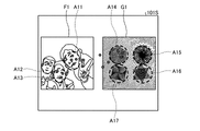
まず、図8ないし図11を用いて、評価用画像の例について説明する。図8は、評価用画像の一例を示す図である。図9は、図8の評価用画像に設定された判定領域の一例を示す図である。図10は、評価用画像の他の例を示す図である。図11は、図10の評価用画像に設定された判定領域の一例を示す図である。 First, an example of an evaluation image will be described with reference to FIGS. 8 to 11. FIG. 8 is a diagram showing an example of an evaluation image. FIG. 9 is a diagram showing an example of a determination area set in the evaluation image of FIG. FIG. 10 is a diagram showing another example of the evaluation image. FIG. 11 is a diagram showing an example of a determination area set in the evaluation image of FIG. 10.
ここで示す評価用画像は、自然画と幾何学画像とを含む。発達障がい者は、自然画よりも幾何学画像の映像を好むためである。また、ASDであると診断された被験者は、他者の存在への無関心、人より物への興味の強さ、特定の物への興味(こだわり)が一般的な傾向とされるためである。自然画は、幾何学画像以外の、自然物または自然物を連想させるような画像であればよい。例えば、人物、動物、植物、及び自然の景観などをカメラで撮像した画像(静止画、動画)を自然画として用いてもよい。また、人物及び動物などを模したキャラクタの画像(静止画、動画)を自然画として用いてもよい。 The evaluation image shown here includes a natural image and a geometric image. This is because people with developmental disabilities prefer geometric images to natural images. In addition, subjects diagnosed with ASD generally tend to be indifferent to the existence of others, more interested in things than people, and interested in specific things (stickiness). .. The natural image may be an image other than a geometric image that is reminiscent of a natural object or a natural object. For example, an image (still image, moving image) obtained by a camera of a person, an animal, a plant, a natural landscape, or the like may be used as a natural image. Further, an image (still image, moving image) of a character imitating a person, an animal, or the like may be used as a natural image.
図8に示す評価用画像は、左側に自然画F1である人物映像を表示し、右側に幾何学画像G1を表示している。ここでは、自然画F1と幾何学画像G1との色彩、輝度、動きなどを近いように設計されている。 In the evaluation image shown in FIG. 8, a person image which is a natural image F1 is displayed on the left side, and a geometric image G1 is displayed on the right side. Here, the colors, luminance, movements, etc. of the natural image F1 and the geometric image G1 are designed to be close to each other.
また、図9に示すように、評価のため、評価用画像には、人物の顔付近に円形状の判定領域A11、判定領域A12及び判定領域A13を設定し、幾何学模様部分に円形状の判定領域A14、判定領域A15、判定領域A16及び判定領域A17を設定している。判定領域A11、判定領域A12、判定領域A13、判定領域A14、判定領域A15、判定領域A16及び判定領域A17は、表示部101Sには表示されない。これらの判定領域を注視したかを示す判定値を積算した、評価データである評価値を求めることにより、被験者が定型発達に近いか、発達障がいの可能性が高いか低いかを評価する。
Further, as shown in FIG. 9, for evaluation, a circular determination area A11, a determination area A12, and a determination area A13 are set in the vicinity of the face of a person, and the geometric pattern portion has a circular shape. The determination area A14, the determination area A15, the determination area A16, and the determination area A17 are set. The determination area A11, the determination area A12, the determination area A13, the determination area A14, the determination area A15, the determination area A16, and the determination area A17 are not displayed on the
図10に示す評価用画像は、図8に対して、右側に自然画F2を表示し、左側に幾何学画像G2を表示している。図11に示すように、人物の顔付近に円形状の判定領域A22及び判定領域A23を設定し、幾何学模様部分に円形状の判定領域A21を設定している。これは、このような評価用画像を見せる場合、被験者の癖で右から見始める場合や、左をより多く見る場合などがあり、この影響を軽減するために左右配置の異なった映像を同数制作し、これを見せる方法(カウンターバランス)がある。しかしながら、この影響を完全に取ることは困難である。 In the evaluation image shown in FIG. 10, the natural image F2 is displayed on the right side and the geometric image G2 is displayed on the left side with respect to FIG. 8. As shown in FIG. 11, a circular shape determination area A22 and a determination area A23 are set near the face of a person, and a circular shape determination area A21 is set in the geometric pattern portion. This is because when showing such an evaluation image, there are cases where the subject starts to look from the right due to his habit, or when he looks at the left more, and in order to mitigate this effect, the same number of images with different left and right arrangements are produced. However, there is a way to show this (counterbalance). However, it is difficult to completely take this effect.
通常、複数の自然画と幾何学画像との組み合わせであるパターンなど複数の評価用画像を被験者に見せて、総合的に発達障がいの可能性が高いか低いかを評価する。これは、偶然性を排除するためと、たまたま好みに近い映像が出て、発達障がいの特性と異なる見方をしてしまう場合の影響を軽減するためである。そこで、例えば、評価用画像を図8→図10というように視聴してもらう。 Usually, a plurality of evaluation images such as a pattern, which is a combination of a plurality of natural images and geometric images, are shown to the subject to comprehensively evaluate whether the possibility of developmental disorder is high or low. This is to eliminate chances and to reduce the effects of accidentally producing images that are close to one's taste and giving a different perspective to the characteristics of developmental disorders. Therefore, for example, the evaluation image is viewed as shown in FIG. 8 → FIG.
上記のような評価用画像を被験者に視認させると、被験者が発達障がい者である場合、人物映像よりも幾何学画像に対して興味を示す傾向にある。また、被験者が発達障がい者である場合、特定の物への興味を示す傾向がある。この場合、注視点Pが幾何学画像に移動し、幾何学画像を人物映像よりも注視する傾向にある。一方、被験者が発達障がい者ではない場合、特定の物への興味を示す傾向がないため、特定の画像を強い興味を示す傾向は見られない。この場合、注視点Pは画像中を多く移動して、多くの領域を注視する傾向にある。 When the subject is made to visually recognize the evaluation image as described above, when the subject is a person with a developmental disorder, he / she tends to be more interested in the geometric image than the human image. Also, if the subject is a developmentally disabled person, they tend to show an interest in a particular object. In this case, the gazing point P moves to the geometric image and tends to gaze at the geometric image rather than the portrait image. On the other hand, when the subject is not a person with a developmental disorder, there is no tendency to show a strong interest in a specific image because there is no tendency to show an interest in a specific object. In this case, the gazing point P tends to move a lot in the image and gaze at a lot of areas.
このため、例えば以下の手順を行うことにより、被験者を評価することが可能である。本実施形態では、表示部101Sに評価画像を提示しながら、同時に被験者の注視点Pを測定し、評価画像中に設定された判定領域に対する注視判定を行う。被験者の注視点Pが判定領域に入った場合、その被験者は該当の注視対象を見たと判断し、複数の評価用画像に対して被験者が見た判定領域の総数を評価値とする。ASD被験者は上記の理由によって相対的に評価値が低くなる傾向があるため、精度良くASDの診断支援を行うことが可能である。
Therefore, it is possible to evaluate the subject, for example, by performing the following procedure. In the present embodiment, while presenting the evaluation image to the
判定部218は、注視点Pが判定領域に入った場合、判定領域の判定値を「1」とする。演算部220は、注視点Pが存在する判定領域の積算した総数を算出する。
When the gazing point P enters the determination area, the
本実施形態において、評価部224は、例えば、複数の画像における判定領域毎の判定値を積算することで、評価の判定を行うことが可能である。評価部224は、評価値が大きいほど、被験者の関心度は特定の物への興味を示す傾向はないと評価を判定することが可能である。また、この場合、被験者が発達障がい者である可能性は低いと評価することが可能である。評価部224は、評価値が小さいほど、被験者の関心度は幾何学画像の方が高い、または、特定の物への興味を示す傾向がある、と評価を判定することが可能である。また、この場合、被験者が発達障がい者である可能性は高いと評価を判定することが可能である。
In the present embodiment, the
ここで、図8に示す評価用画像の判定領域毎の判定値を、X[判定領域]と表す。例えば、判定領域A11の判定値は、X[A11]と表し、判定領域A14の判定値は、X[A14]と表す。なお、注視点Pが一度も内部に存在しなかった判定領域の判定値は「0」、注視点Pが内部に存在した判定領域の判定値は「1」である。 Here, the determination value for each determination area of the evaluation image shown in FIG. 8 is represented by X [determination area]. For example, the determination value of the determination area A11 is expressed as X [A11], and the determination value of the determination area A14 is expressed as X [A14]. The determination value of the determination area in which the gazing point P has never existed inside is "0", and the determination value of the determination area in which the gazing point P has existed inside is "1".
この場合、図8に示す評価用画像に対する評価値ANS1は、各判定領域の判定値を積算し、
ANS1=X[A11]+X[A12]+X[A13]+X[A14]+X[A15]+X[A16]+X[A17]
と表される。
In this case, the evaluation value ANS1 for the evaluation image shown in FIG. 8 is obtained by integrating the judgment values of each judgment area.
ANS1 = X [A11] + X [A12] + X [A13] + X [A14] + X [A15] + X [A16] + X [A17]
It is expressed as.
図10に示す評価用画像に対する評価値ANS2は、各判定領域の判定値を積算し、
ANS2=X[A21]+X[A22]+X[A23]
と表される。
The evaluation value ANS2 for the evaluation image shown in FIG. 10 is obtained by integrating the judgment values of each judgment area.
ANS2 = X [A21] + X [A22] + X [A23]
It is expressed as.
これらより、図8に示す評価用画像に対する評価値ANS1と図10に示す評価用画像に対する評価値ANS2とを積算して、被験者の評価値ANSは、例えば、
ANS=ANS1+ANS2
と表される。
From these, the evaluation value ANS1 for the evaluation image shown in FIG. 8 and the evaluation value ANS2 for the evaluation image shown in FIG. 10 are integrated, and the evaluation value ANS of the subject is, for example,
ANS = ANS1 + ANS2
It is expressed as.
図12、図14を用いて、被験者Aの評価値ANSについて説明する。図12は、図8の評価用画像に対する注視点の一例を示す図である。図14は、図10の評価用画像に対する注視点の一例を示す図である。 The evaluation value ANS of the subject A will be described with reference to FIGS. 12 and 14. FIG. 12 is a diagram showing an example of a gazing point for the evaluation image of FIG. FIG. 14 is a diagram showing an example of a gazing point with respect to the evaluation image of FIG.
被験者Aの図8に示す評価用画像に対する評価値ANS1は、
ANS1=1+0+1+1+0+0+0=3
と算出される。
The evaluation value ANS1 for the evaluation image shown in FIG. 8 of the subject A is
ANS1 = 1 + 0 + 1 + 1 + 0 + 0 + 0 = 3
Is calculated.
被験者Aの図10に示す評価用画像に対する評価値ANS2は、
ANS2=1+0+1=2
と算出される。
The evaluation value ANS2 for the evaluation image shown in FIG. 10 of the subject A is
ANS2 = 1 + 0 + 1 = 2
Is calculated.
これらより、被験者Aの評価値ANSは、
ANS=3+2=5
と算出される。
From these, the evaluation value ANS of subject A is
ANS = 3 + 2 = 5
Is calculated.
例えば、ASDの可能性が高いか否かを判断するしきい値を「7」とすると、被験者Aの評価値ANSはしきい値以上ではないので、「ASDの可能性が高い」と判断する。 For example, if the threshold value for determining whether or not the possibility of ASD is high is "7", the evaluation value ANS of subject A is not equal to or higher than the threshold value, and therefore it is determined that "the possibility of ASD is high". ..
図13、図15を用いて、被験者Bの評価値ANSについて説明する。図13は、図8の評価用画像に対する注視点の他の例を示す図である。図15は、図10の評価用画像に対する注視点の他の例を示す図である。 The evaluation value ANS of the subject B will be described with reference to FIGS. 13 and 15. FIG. 13 is a diagram showing another example of the gazing point for the evaluation image of FIG. FIG. 15 is a diagram showing another example of the gazing point for the evaluation image of FIG.
被験者Bの図8に示す評価用画像に対する評価値ANS1は、
ANS1=1+1+1+1+1+1+0=6
と算出される。
The evaluation value ANS1 for the evaluation image shown in FIG. 8 of the subject B is
ANS1 = 1 + 1 + 1 + 1 + 1 + 1 + 0 = 6
Is calculated.
被験者Bの図10に示す評価用画像に対する評価値ANS2は、
ANS2=1+1+1=3
と算出される。
The evaluation value ANS2 for the evaluation image shown in FIG. 10 of the subject B is
ANS2 = 1 + 1 + 1 = 3
Is calculated.
これらより、被験者Bの評価値ANSは、
ANS=6+3=9
と算出される。
From these, the evaluation value ANS of subject B is
ANS = 6 + 3 = 9
Is calculated.
例えば、ASDの可能性が高いか否かを判断するしきい値を「7」とすると、被験者Bの評価値ANSはしきい値以上であるので、「ASDの可能性が低い」と判断する。 For example, if the threshold value for determining whether or not the possibility of ASD is high is "7", the evaluation value ANS of subject B is equal to or higher than the threshold value, and therefore it is determined that "the possibility of ASD is low". ..
また、評価値は、判定領域毎の判定値に重み付けをして算出してもよい。 Further, the evaluation value may be calculated by weighting the judgment value for each judgment area.
重み付けの第一の方法は、同一画像内の判定領域毎に重み付けを行う方法である。例えば、自然画に設定された判定領域に対して重み付けを行う。この場合、評価値ANS1、評価値ANS2は、以下のように表される。なお、Kは、重みづけのための係数である。係数Kは、適宜設定することができる。
ANS1=X[A11]・K+X[A12]・K+X[A13]・K+X[A14]+X[A15]+X[A16]+X[A17]
ANS2=X[A21]+X[A22]・K+X[A23]・K
The first method of weighting is a method of weighting each determination area in the same image. For example, weighting is performed on the determination area set in the natural image. In this case, the evaluation value ANS1 and the evaluation value ANS2 are expressed as follows. In addition, K is a coefficient for weighting. The coefficient K can be set as appropriate.
ANS1 = X [A11], K + X [A12], K + X [A13], K + X [A14] + X [A15] + X [A16] + X [A17]
ANS2 = X [A21] + X [A22] ・ K + X [A23] ・ K
ここで、係数Kを「2」とした場合、被験者Aの評価値は、以下のように算出される。
ANS1=2+0+2+1+0+0+0=5
ANS2=1+0+2=3
ANS=8
Here, when the coefficient K is set to "2", the evaluation value of the subject A is calculated as follows.
ANS1 = 2 + 0 + 2 + 1 + 0 + 0 + 0 = 5
ANS2 = 1 + 0 + 2 = 3
ANS = 8
重み付けを行う、言い換えると、重要視する判定領域の選定方法は、既知の臨床的な知見によるもの、または、計測結果から診断感度が高くなるように選択する方法などが考えられる。また、係数Kの値は判定領域毎に異なる値を設定することもできる。 Weighting, in other words, a method of selecting an important determination region may be based on known clinical knowledge, or may be selected so that the diagnostic sensitivity is high based on the measurement results. Further, the value of the coefficient K may be set to a different value for each determination area.
重み付けの第二の方法は、評価用画像毎に重み付けを行う方法である。例えば、図10に示す評価用画像に対して重み付けを行う。この場合、評価値ANS1、評価値ANS2は、以下のように表される。
ANS1=X[A11]+X[A12]+X[A13]+X[A14]+X[A15]+X[A16]+X[A17]
ANS2=(X[A21]+X[A22]+X[A23])・K
The second method of weighting is a method of weighting each evaluation image. For example, weighting is performed on the evaluation image shown in FIG. In this case, the evaluation value ANS1 and the evaluation value ANS2 are expressed as follows.
ANS1 = X [A11] + X [A12] + X [A13] + X [A14] + X [A15] + X [A16] + X [A17]
ANS2 = (X [A21] + X [A22] + X [A23]) · K
ここで、係数Kを「2」とした場合、被験者Aの評価値は、以下のように算出される。
ANS1=3
ANS2=4
ANS=7
Here, when the coefficient K is set to "2", the evaluation value of the subject A is calculated as follows.
ANS1 = 3
ANS2 = 4
ANS = 7
重み付けを行う、言い換えると、重要視する評価用画像の選定方法は、既知の臨床的な知見によるもの、または、計測結果から診断感度が高くなるように選択する方法などが考えられる。また、係数Kの値は評価用画像毎に異なる値を設定することもできる。 The method of selecting the evaluation image to be weighted, in other words, to be emphasized, may be based on known clinical knowledge, or may be selected from the measurement results so that the diagnostic sensitivity is high. Further, the value of the coefficient K can be set to a different value for each evaluation image.
図16、図17を用いて、評価用画像の他の例について説明する。図16は、評価用画像の他の例を示す図である。図17は、図16の評価用画像に設定された判定領域の一例を示す図である。評価用画像は、自然画と幾何学画像とを含むものに限定されない。評価用画像は、複数の物体を含む1つの自然画であってもよい。 16 and 17 will be used to describe other examples of the evaluation image. FIG. 16 is a diagram showing another example of the evaluation image. FIG. 17 is a diagram showing an example of a determination area set in the evaluation image of FIG. The evaluation image is not limited to those including a natural image and a geometric image. The evaluation image may be one natural image including a plurality of objects.
図16に示す評価用画像は、複数の物体を含む自然画F3である。自然画F3には、例えば、自動車、自動車の運転手、信号機、点灯中の青信号、看板、看板に書かれた文字、歩行者、動物、横断歩道などが含まれる。 The evaluation image shown in FIG. 16 is a natural image F3 including a plurality of objects. The natural picture F3 includes, for example, a car, a driver of a car, a traffic light, a green light in light, a signboard, characters written on the signboard, a pedestrian, an animal, a pedestrian crossing, and the like.
また、図17に示すように、評価のため、評価用画像には、自動車に判定領域A31、自動車の運転者に判定領域A32、信号機に判定領域A33、点灯中の青信号に判定領域A34、看板に判定領域A35、看板に書かれた文字に判定領域A36、歩行者に判定領域A37、動物に判定領域A38、及び、横断歩道に判定領域A39を設定している。また、判定領域A31の中に判定領域A32を設定し、判定領域A33の中に判定領域A34を設定し、判定領域A35の中に判定領域A36を設定している。この場合、内側の判定領域A32、判定領域A34、及び、判定領域A36の内部に注視点Pが存在すると判定する場合、外側の判定領域A31、判定領域A33、及び、判定領域A35の内部にも注視点Pが存在するとして判定する。 Further, as shown in FIG. 17, for evaluation, the evaluation image includes a determination area A31 for an automobile, a determination area A32 for an automobile driver, a determination area A33 for a traffic light, a determination area A34 for a lit green light, and a signboard. The determination area A35, the determination area A36 for the characters written on the signboard, the determination area A37 for the pedestrian, the determination area A38 for the animal, and the determination area A39 for the pedestrian crossing are set. Further, the determination area A32 is set in the determination area A31, the determination area A34 is set in the determination area A33, and the determination area A36 is set in the determination area A35. In this case, when it is determined that the gazing point P exists inside the inner determination area A32, the determination area A34, and the determination area A36, the outside determination area A31, the determination area A33, and the inside of the determination area A35 are also determined. It is determined that the gazing point P exists.
評価部224は、評価データである評価値ANSが所定のしきい値以上か否かを判断して、評価の判定を行う。例えば評価値ANSがしきい値以上である場合、被験者がASDである可能性は低いと評価を判定することができる。また、評価値ANSが所定のしきい値以上ではない場合、被験者がASDである可能性は高いと評価を判定することができる。
The
本実施形態において、出力制御部226は、評価部224が評価結果を出力した場合、評価結果に応じて、例えば「被験者は発達障がい者である可能性が低いと思われます」の文字データや、「被験者は発達障がい者である可能性が高いと思われます」の文字データ等を出力装置50に出力させる。
In the present embodiment, when the
次に、本実施形態に係る評価方法の一例について、図18を参照しながら説明する。図18は、本実施形態に係る評価方法の一例を示すフローチャートである。 Next, an example of the evaluation method according to the present embodiment will be described with reference to FIG. FIG. 18 is a flowchart showing an example of the evaluation method according to the present embodiment.
注視点検出部214は、注視点検出を開始させる(ステップS101)。そして、ステップS102に進む。
The gazing
表示制御部202は、表示部101Sに1枚目の評価用画像を表示させる(ステップS102)。本実施形態では、表示制御部202は、表示部101Sに図8に示す評価用画像を表示させる。そして、ステップS103に進む。
The
演算部220は、1枚目の評価用画像に設定された判定領域の判定値を「0」にする(ステップS103)。本実施形態では、演算部220は、1枚目の評価用画像に設定された判定領域A11ないし判定領域A17の判定値を「0」にする。そして、ステップS104に進む。
The
注視点検出部214は、被験者の評価用画像における注視点Pを取得する(ステップS104)。より詳しくは、注視点検出部214は、表示装置101に表示された1枚目の評価用画像を被験者に見せた状態で、規定のサンプリング周期(例えば20[msec])毎に、表示装置101の表示部101Sにおける被験者の注視点Pの位置データを検出する。そして、ステップS105に進む。
The gazing
判定部218は、注視点Pの座標が判定領域A11ないし判定領域A17の内部に存在するかを判定する(ステップS105)。より詳しくは、判定部218は、サンプリング周期(例えば20[msec])毎に、注視点検出部214が検出した位置データに基づいて注視点Pが存在する判定領域を判定する。
The
注視点Pが判定領域A11ないし判定領域A17の内部に存在すると判定された場合(ステップS105でYes)、判定部218は、注視点Pが存在すると判定された判定領域の判定値を「1」に変更する(ステップS106)。そして、ステップS107に進む。
When it is determined that the gazing point P exists inside the determination area A11 to the determination area A17 (Yes in step S105), the
注視点Pが判定領域A11ないし判定領域A17の内部に存在しないと判定された場合(ステップS105でNo)、ステップS107に進む。 If it is determined that the gazing point P does not exist inside the determination area A11 or the determination area A17 (No in step S105), the process proceeds to step S107.
演算部220は、検出タイマの検出結果に基づいて、1枚目の評価用映像の再生が完了する時刻に到達したか否かを判断する(ステップS107)。本実施形態では、1枚目の評価用映像の再生開始から3[sec]が経過すると、1枚目の評価用映像の再生が完了する時刻に到達したと判断する。演算部220により1枚目の評価用映像の再生が完了する時刻に到達したと判断された場合(ステップS107のYes)、ステップS108に進む。本実施形態では、1枚目の評価用映像の再生開始から3[sec]が経過していないと、1枚目の評価用映像の再生が完了する時刻に到達していないと判断する。演算部220により1枚目の評価用映像の再生が完了する時刻に到達していないと判断された場合(ステップS107のNo)、上記のステップS104以降の処理を繰り返し行う。
Based on the detection result of the detection timer, the
演算部220により1枚目の評価用映像の再生が完了する時刻に到達したと判断された場合(ステップS107のYes)、表示制御部202は、表示部101Sに2枚目の評価用画像を表示させる(ステップS108)。本実施形態では、表示制御部202は、表示部101Sに図10に示す評価用画像を表示させる。そして、ステップS109に進む。
When it is determined by the
演算部220は、2枚目の評価用画像に設定された判定領域の判定値を「0」にする(ステップS109)。本実施形態では、演算部220は、2枚目の評価用画像に設定された判定領域A21ないし判定領域A23の判定値を「0」にする。そして、ステップS110に進む。
The
注視点検出部214は、被験者の評価用画像における注視点Pを取得する(ステップS110)。より詳しくは、注視点検出部214は、表示装置101に表示された2枚目の評価用画像を被験者に見せた状態で、規定のサンプリング周期(例えば20[msec])毎に、表示装置101の表示部101Sにおける被験者の注視点Pの位置データを検出する。そして、ステップS111に進む。
The gazing
判定部218は、注視点Pの座標が判定領域A21ないし判定領域A23の内部に存在するかを判定する(ステップS111)。より詳しくは、判定部218は、サンプリング周期(例えば20[msec])毎に、注視点検出部214が検出した位置データに基づいて注視点Pが存在する判定領域を判定する。
The
注視点Pが判定領域A21ないし判定領域A23の内部に存在すると判定された場合(ステップS111でYes)、判定部218は、注視点Pが存在する判定領域の判定値を「1」に変更する(ステップS112)。そして、ステップS113に進む。
When it is determined that the gazing point P exists inside the determination area A21 or the determination area A23 (Yes in step S111), the
注視点Pが判定領域A21ないし判定領域A23の内部に存在しないと判定された場合(ステップS111でNo)、ステップS113に進む。 If it is determined that the gazing point P does not exist inside the determination area A21 or the determination area A23 (No in step S111), the process proceeds to step S113.
演算部220は、検出タイマの検出結果に基づいて、2枚目の評価用映像の再生が完了する時刻に到達したか否かを判断する(ステップS113)。本実施形態では、2枚目の評価用映像の再生開始から3[sec]が経過すると、2枚目の評価用映像の再生が完了する時刻に到達したと判断する。演算部220により2枚目の評価用映像の再生が完了する時刻に到達したと判断された場合(ステップS113のYes)、ステップS114に進む。本実施形態では、2枚目の評価用映像の再生開始から3[sec]が経過していないと、2枚目の評価用映像の再生が完了する時刻に到達していないと判断する。演算部220により2枚目の評価用映像の再生が完了する時刻に到達していないと判断された場合(ステップS113のNo)、上記のステップS110以降の処理を繰り返し行う。
Based on the detection result of the detection timer, the
評価部224は、注視点Pが存在する判定領域の総数に基づいて、被験者の評価値を算出する(ステップS114)。演算部220は、1枚目の評価用画像に対する判定値を積算して評価値ANS1を算出する。また、演算部220は、2枚目の評価用画像に対する判定値を積算して評価値ANS2を算出する。評価部224は、1枚目の評価用画像に対する評価値ANS1と、2枚目の評価用画像に対する評価値ANS2とを積算して、被験者の評価値ANSを算出する。そして、ステップS115に進む。
The
評価部224は、算出した評価値ANSがしきい値以上であるか否かを判断する(ステップS115)。本実施形態では、評価部224は、評価値ANSがしきい値「7」以上であるか否かを判断する。
The
評価部224は、算出した評価値ANSがしきい値以上ではないと判断する場合(ステップS115でNo)、被験者は「ASDの可能性が高い」と評価を判定する(ステップS116)。その後、出力制御部226は、評価部224で判定した評価結果を出力して、処理を終了する。
When the
評価部224は、算出した評価値ANSがしきい値以上であると判断する場合(ステップS115でYes)、被験者は「ASDの可能性が低い」と評価を判定する(ステップS117)。その後、出力制御部226は、評価部224で判定した評価結果を出力して、処理を終了する。
When the
以上のように、本実施形態に係る評価装置は、画像を表示する表示部101Sと、表示部101Sを観察する被験者の注視点Pの位置を検出する注視点検出部214と、表示部101Sにおいて、判定領域を設定する領域設定部216と、注視点Pの位置データに基づいて、注視点Pが判定領域の内部に存在するか否かをそれぞれ判定する判定部218と、判定部218の判定結果に基づいて、注視点Pが存在する判定領域の総数を算出する演算部220と、演算部220が算出した注視点Pが存在する判定領域の総数に基づいて、被験者の評価データを求める評価部224とを備える。
As described above, in the evaluation device according to the present embodiment, the
また、本実施形態に係る評価方法は、表示部101Sに画像を表示する表示ステップと、表示部101Sを観察する被験者の注視点Pの位置を検出する注視点検出ステップと、表示部101Sにおいて、判定領域を設定する領域設定ステップと、注視点Pの位置データに基づいて、注視点Pが判定領域の内部に存在するか否かをそれぞれ判定する判定ステップと、判定ステップにおける判定結果に基づいて、注視点Pが存在する判定領域の総数を算出する演算ステップと、演算ステップによって算出された注視点Pが存在する判定領域の総数に基づいて、被験者の評価データを求める評価ステップとを含む。
Further, the evaluation method according to the present embodiment includes a display step of displaying an image on the
また、本実施形態に係る評価プログラムは、表示部101Sに画像を表示する表示ステップと、表示部101Sを観察する被験者の注視点Pの位置を検出する注視点検出ステップと、表示部101Sにおいて、判定領域を設定する領域設定ステップと、注視点Pの位置データに基づいて、注視点Pが判定領域の内部に存在するか否かをそれぞれ判定する判定ステップと、判定ステップにおける判定結果に基づいて、注視点Pが存在する判定領域の総数を算出する演算ステップと、演算ステップによって算出された注視点Pが存在する判定領域の総数に基づいて、被験者の評価データを求める評価ステップとをコンピュータに実行させる。
Further, the evaluation program according to the present embodiment includes a display step of displaying an image on the
本実施形態によれば、注視点Pが存在する判定領域の総数に基づいて、言い換えると、評価用画像中の判定領域をいくつ見たかによって、被験者の評価データを求めることができる。本実施形態は、被験者のASDの診断支援を簡単かつ高精度に行うことができる。 According to the present embodiment, the evaluation data of the subject can be obtained based on the total number of determination regions in which the gazing point P exists, in other words, depending on how many determination regions are viewed in the evaluation image. This embodiment can easily and accurately support the diagnosis of ASD of a subject.
本実施形態では、領域設定部216は、画像に含まれる人物、物体、模様などに判定領域を複数設定する。ASDの被験者は、特定の物への強い興味を示す傾向があるので、複数の判定領域のうちいずれかをより注視する可能性が高い。このように、本実施形態によれば、高精度の評価データを効率的に得ることができる。
In the present embodiment, the
本実施形態では、評価部224は、注視点Pが存在する判定領域毎に重みをつけて評価データを求める。これにより、既知の臨床的な知見によるもの、または、計測結果から診断感度が高くなるように選択する方法などを使用して、各データに適切に優先順位をつけることができる。本実施形態によれば、より高精度の評価データを得ることができる。
In the present embodiment, the
本実施形態では、評価部224は、評価データが所定のしきい値以上であるか否かを判断することによって、評価の判定を行う。本実施形態によれば、より高精度の評価データを容易に得ることができる。
In the present embodiment, the
本発明の技術範囲は上記実施形態に限定されるものではなく、本発明の趣旨を逸脱しない範囲で適宜変更を加えることができる。例えば、上記各実施形態では、視線検出装置100を、ASDである可能性を評価する評価装置として用いる場合を例に挙げて説明したが、これに限定されない。例えば、視線検出装置100を、注意欠陥・多動性障がい(ADHD:Attention-deficit hyperactivity disorder)であるか可能性を評価する評価装置にも適用可能である。
The technical scope of the present invention is not limited to the above-described embodiment, and changes can be made as appropriate without departing from the spirit of the present invention. For example, in each of the above embodiments, the case where the line-of-
A11~A17…判定領域、A21~A23…判定領域、P…注視点、ANS…評価値、20…コンピュータシステム、100…視線検出装置、101…表示装置、101S…表示部、102…ステレオカメラ装置、103…照明装置、202…表示制御部、214…注視点検出部、216…領域設定部、218…判定部、220…演算部、222…記憶部、224…評価部、226…出力制御部 A11 to A17 ... Judgment area, A21 to A23 ... Judgment area, P ... Gaze point, ANS ... Evaluation value, 20 ... Computer system, 100 ... Line of sight detection device, 101 ... Display device, 101S ... Display unit, 102 ... Stereo camera device , 103 ... Lighting device, 202 ... Display control unit, 214 ... Gaze point detection unit, 216 ... Area setting unit, 218 ... Judgment unit, 220 ... Calculation unit, 222 ... Storage unit, 224 ... Evaluation unit, 226 ... Output control unit
Claims (8)
前記表示部を観察する被験者の注視点の位置データを検出する注視点検出部と、
前記表示部における前記評価用画像に対応する位置に判定領域を設定する領域設定部と、
前記注視点の位置データに基づいて、前記注視点が前記判定領域の内部に存在するか否かをそれぞれ判定する判定部と、
前記判定部の判定結果に基づいて、所定時間に前記注視点が存在する前記判定領域の数を算出する演算部と、
前記演算部が算出した前記注視点が存在する前記判定領域の数に基づいて、前記被験者が発達障がい者である可能性を評価する評価データを求める評価部と、
を備え、
前記領域設定部は、ASD(Autism Spectrum Disorder)の可能性が高い被験者と、ASDの可能性が低い被験者とで注視するか否かの傾向に差異が出る領域の少なくとも一部に判定領域を設定する、
評価装置。 A display unit that displays an image for evaluation and
A gaze point detection unit that detects the position data of the gaze point of the subject observing the display unit, and
An area setting unit that sets a determination area at a position corresponding to the evaluation image on the display unit, and
Based on the position data of the gazing point, a determination unit for determining whether or not the gazing point exists inside the determination area, and a determination unit.
A calculation unit that calculates the number of the determination regions in which the gazing point exists at a predetermined time based on the determination result of the determination unit.
An evaluation unit that obtains evaluation data for evaluating the possibility that the subject is a person with a developmental disorder based on the number of determination regions in which the gazing point exists calculated by the calculation unit.
Equipped with
The area setting unit sets a determination area in at least a part of an area where there is a difference in the tendency of whether or not to gaze between a subject having a high possibility of ASD (Autism Spectrum Disorder) and a subject having a low possibility of ASD. do,
Evaluation device.
請求項1に記載の評価装置。 The evaluation unit obtains the evaluation data of the subject based on the calculation formula that the value of the evaluation data increases as the number of the determination regions in which the gazing point exists, which is calculated by the calculation unit, increases. The higher the value of, the less likely the subject is to have a developmental disability.
The evaluation device according to claim 1.
請求項1または2に記載の評価装置。 The evaluation unit further determines whether or not the value of the evaluation data is equal to or higher than a predetermined threshold value, and determines the evaluation.
The evaluation device according to claim 1 or 2.
前記表示部を観察する被験者の注視点の位置データを検出する注視点検出部と、
前記表示部における前記評価用画像に対応する位置に判定領域を設定する領域設定部と、
前記注視点の位置データに基づいて、前記注視点が前記判定領域の内部に存在するか否かをそれぞれ判定する判定部と、
前記判定部の判定結果に基づいて、所定時間に前記注視点が存在する前記判定領域の数を算出する演算部と、
前記演算部が算出した前記注視点が存在する前記判定領域の数に基づいて、前記被験者が発達障がい者である可能性を評価する評価データを求める評価部と、
を備え、
前記評価用画像は、自然画と幾何学画像とを含み、
前記領域設定部は、前記自然画が表示された領域の少なくとも一部と、前記幾何学画像が表示された領域の少なくとも一部とにそれぞれ判定領域を設定し、
前記評価部は、前記自然画に設定された評価領域の方が前記幾何学画像に設定された評価領域よりも判定値が高くなるように前記判定値の重み付けを行い、前記判定値を積算することにより前記評価データを算出する評価装置。 A display unit that displays an image for evaluation and
A gaze point detection unit that detects the position data of the gaze point of the subject observing the display unit, and
An area setting unit that sets a determination area at a position corresponding to the evaluation image on the display unit, and
Based on the position data of the gazing point, a determination unit for determining whether or not the gazing point exists inside the determination area, and a determination unit.
A calculation unit that calculates the number of the determination regions in which the gazing point exists at a predetermined time based on the determination result of the determination unit.
An evaluation unit that obtains evaluation data for evaluating the possibility that the subject is a person with a developmental disorder based on the number of determination regions in which the gazing point exists calculated by the calculation unit.
Equipped with
The evaluation image includes a natural image and a geometric image.
The area setting unit sets determination areas in at least a part of the area where the natural image is displayed and at least a part of the area where the geometric image is displayed.
The evaluation unit weights the judgment values so that the evaluation area set in the natural image has a higher judgment value than the evaluation area set in the geometric image, and integrates the judgment values. An evaluation device that calculates the evaluation data.
表示部に評価用画像を表示する表示ステップと、
前記表示部を観察する前記被験者の注視点の位置データを検出する注視点検出ステップと、
前記表示部におけるASD(Autism Spectrum Disorder)の可能性が高い被験者と、ASDの可能性が低い被験者とで注視するか否かの傾向に差異が出る領域の少なくとも一部に判定領域を設定する領域設定ステップと、
前記注視点の位置データに基づいて、前記注視点が前記判定領域の内部に存在するか否かをそれぞれ判定し、判定データを出力する判定ステップと、
前記判定ステップにおける判定結果である前記判定データに基づいて、所定時間に前記注視点が存在する前記判定領域の数を算出する演算ステップと、
前記演算ステップによって算出された前記注視点が存在する前記判定領域の数に基づいて、前記被験者が発達障がい者である可能性を評価する評価データを求める評価ステップと、
を含む評価方法。 It is an evaluation method performed by an evaluation device that evaluates the possibility that a subject is a person with a developmental disorder.
A display step that displays an evaluation image on the display unit,
A gaze point detection step for detecting the position data of the gaze point of the subject who observes the display unit, and
An area in which a determination area is set in at least a part of an area in the display unit where there is a difference in the tendency of whether or not to gaze between a subject having a high possibility of ASD (Autism Spectrum Disorder) and a subject having a low possibility of ASD. Setting steps and
A determination step of determining whether or not the gazing point exists inside the determination area based on the position data of the gazing point and outputting the determination data .
A calculation step for calculating the number of the determination regions in which the gazing point exists at a predetermined time based on the determination data which is the determination result in the determination step.
An evaluation step for obtaining evaluation data for evaluating the possibility that the subject is a person with a developmental disorder based on the number of determination regions in which the gazing point exists, which is calculated by the calculation step.
Evaluation method including.
前記表示部を観察する被験者の注視点の位置データを検出する注視点検出ステップと、
前記表示部におけるASD(Autism Spectrum Disorder)の可能性が高い被験者と、ASDの可能性が低い被験者とで注視するか否かの傾向に差異が出る領域の少なくとも一部に判定領域を設定する領域設定ステップと、
前記注視点の位置データに基づいて、前記注視点が前記判定領域の内部に存在するか否かをそれぞれ判定し、判定データを出力する判定ステップと、
前記判定ステップにおける判定結果である前記判定データに基づいて、所定時間に前記注視点が存在する前記判定領域の数を算出する演算ステップと、
前記演算ステップによって算出された前記注視点が存在する前記判定領域の数に基づいて、前記被験者が発達障がい者である可能性を評価する評価データを求める評価ステップと、
をコンピュータに実行させる評価プログラム。 A display step that displays an evaluation image on the display unit,
A gaze point detection step for detecting the position data of the gaze point of the subject observing the display unit, and
An area in which a determination area is set in at least a part of an area in the display unit where there is a difference in the tendency of whether or not to gaze between a subject having a high possibility of ASD (Autism Spectrum Disorder) and a subject having a low possibility of ASD. Setting steps and
A determination step of determining whether or not the gazing point exists inside the determination area based on the position data of the gazing point and outputting the determination data .
A calculation step for calculating the number of the determination regions in which the gazing point exists at a predetermined time based on the determination data which is the determination result in the determination step.
An evaluation step for obtaining evaluation data for evaluating the possibility that the subject is a person with a developmental disorder based on the number of determination regions in which the gazing point exists, which is calculated by the calculation step.
An evaluation program that lets a computer run.
表示部に評価用画像を表示する表示ステップと、A display step that displays an evaluation image on the display unit,
前記表示部を観察する前記被験者の注視点の位置データを検出する注視点検出ステップと、 A gaze point detection step for detecting the position data of the gaze point of the subject who observes the display unit, and
前記表示部における前記評価用画像に対応する位置に判定領域を設定する領域設定ステップと、 An area setting step for setting a determination area at a position corresponding to the evaluation image on the display unit, and
前記注視点の位置データに基づいて、前記注視点が前記判定領域の内部に存在するか否かをそれぞれ判定し、判定データを出力する判定ステップと、 A determination step of determining whether or not the gazing point exists inside the determination area based on the position data of the gazing point and outputting the determination data.
前記判定ステップの判定結果である前記判定データに基づいて、所定時間に前記注視点が存在する前記判定領域の数を算出する演算ステップと、 A calculation step for calculating the number of the determination regions in which the gazing point exists at a predetermined time based on the determination data which is the determination result of the determination step.
前記演算ステップが算出した前記注視点が存在する前記判定領域の数に基づいて、前記被験者が発達障がい者である可能性を評価する評価データを求める評価ステップと、 An evaluation step for obtaining evaluation data for evaluating the possibility that the subject is a person with a developmental disorder based on the number of determination regions in which the gazing point is present calculated by the calculation step.
を含み、 Including
前記評価用画像は、自然画と幾何学画像とを含み、 The evaluation image includes a natural image and a geometric image.
前記領域設定ステップは、前記自然画が表示された領域の少なくとも一部と、前記幾何学画像が表示された領域の少なくとも一部とにそれぞれ判定領域を設定し、 In the area setting step, a determination area is set in at least a part of the area where the natural image is displayed and at least a part of the area where the geometric image is displayed.
前記評価ステップは、前記自然画に設定された評価領域の方が前記幾何学画像に設定された評価領域よりも判定値が高くなるように前記判定値の重み付けを行い、前記判定値を積算することにより前記評価データを算出する評価方法。 In the evaluation step, the judgment value is weighted so that the evaluation area set in the natural image has a higher judgment value than the evaluation area set in the geometric image, and the judgment value is integrated. An evaluation method for calculating the evaluation data.
前記表示部を観察する被験者の注視点の位置データを検出する注視点検出ステップと、 A gaze point detection step for detecting the position data of the gaze point of the subject observing the display unit, and
前記表示部における前記評価用画像に対応する位置に判定領域を設定する領域設定ステップと、 An area setting step for setting a determination area at a position corresponding to the evaluation image on the display unit, and
前記注視点の位置データに基づいて、前記注視点が前記判定領域の内部に存在するか否かをそれぞれ判定し、判定データを出力する判定ステップと、 A determination step of determining whether or not the gazing point exists inside the determination area based on the position data of the gazing point and outputting the determination data.
前記判定ステップの判定結果である前記判定データに基づいて、所定時間に前記注視点が存在する前記判定領域の数を算出する演算ステップと、 A calculation step for calculating the number of the determination regions in which the gazing point exists at a predetermined time based on the determination data which is the determination result of the determination step.
前記演算ステップが算出した前記注視点が存在する前記判定領域の数に基づいて、前記被験者が発達障がい者である可能性を評価する評価データを求める評価ステップと、 An evaluation step for obtaining evaluation data for evaluating the possibility that the subject is a person with a developmental disorder based on the number of determination regions in which the gazing point exists calculated by the calculation step.
を行い、 And
前記評価用画像は、自然画と幾何学画像とを含み、 The evaluation image includes a natural image and a geometric image.
前記領域設定ステップは、前記自然画が表示された領域の少なくとも一部と、前記幾何学画像が表示された領域の少なくとも一部とにそれぞれ判定領域を設定し、 In the area setting step, a determination area is set in at least a part of the area where the natural image is displayed and at least a part of the area where the geometric image is displayed.
前記評価ステップは、前記自然画に設定された評価領域の方が前記幾何学画像に設定された評価領域よりも判定値が高くなるように前記判定値の重み付けを行い、前記判定値を積算することにより前記評価データを算出することをコンピュータに実行させる評価プログラム。 In the evaluation step, the judgment values are weighted so that the evaluation area set in the natural image has a higher judgment value than the evaluation area set in the geometric image, and the judgment values are integrated. An evaluation program that causes a computer to execute the calculation of the evaluation data.
Priority Applications (5)
| Application Number | Priority Date | Filing Date | Title |
|---|---|---|---|
| JP2018233988A JP7057483B2 (en) | 2018-12-14 | 2018-12-14 | Evaluation device, evaluation method, and evaluation program |
| EP19894584.2A EP3878373B1 (en) | 2018-12-14 | 2019-12-06 | Evaluation device, evaluation method, and evaluation program |
| PCT/JP2019/047899 WO2020121975A1 (en) | 2018-12-14 | 2019-12-06 | Evaluation device, evaluation method, and evaluation program |
| CN201980082608.4A CN113194839A (en) | 2018-12-14 | 2019-12-06 | Evaluation device, evaluation method, and evaluation program |
| US17/341,441 US20210290133A1 (en) | 2018-12-14 | 2021-06-08 | Evaluation device, evaluation method, and non-transitory storage medium |
Applications Claiming Priority (1)
| Application Number | Priority Date | Filing Date | Title |
|---|---|---|---|
| JP2018233988A JP7057483B2 (en) | 2018-12-14 | 2018-12-14 | Evaluation device, evaluation method, and evaluation program |
Publications (3)
| Publication Number | Publication Date |
|---|---|
| JP2020092924A JP2020092924A (en) | 2020-06-18 |
| JP2020092924A5 JP2020092924A5 (en) | 2021-08-26 |
| JP7057483B2 true JP7057483B2 (en) | 2022-04-20 |
Family
ID=71076883
Family Applications (1)
| Application Number | Title | Priority Date | Filing Date |
|---|---|---|---|
| JP2018233988A Active JP7057483B2 (en) | 2018-12-14 | 2018-12-14 | Evaluation device, evaluation method, and evaluation program |
Country Status (5)
| Country | Link |
|---|---|
| US (1) | US20210290133A1 (en) |
| EP (1) | EP3878373B1 (en) |
| JP (1) | JP7057483B2 (en) |
| CN (1) | CN113194839A (en) |
| WO (1) | WO2020121975A1 (en) |
Families Citing this family (1)
| Publication number | Priority date | Publication date | Assignee | Title |
|---|---|---|---|---|
| JP2021192164A (en) * | 2020-06-05 | 2021-12-16 | 株式会社Jvcケンウッド | Line-of-sight detection device, line-of-sight detection method, and line-of-sight detection program |
Citations (2)
| Publication number | Priority date | Publication date | Assignee | Title |
|---|---|---|---|---|
| WO2016052646A1 (en) | 2014-09-30 | 2016-04-07 | 国立大学法人浜松医科大学 | Inattention measurement device, system, and method |
| JP2017099513A (en) | 2015-11-30 | 2017-06-08 | 株式会社Jvcケンウッド | Diagnosis support apparatus and diagnosis support method |
Family Cites Families (8)
| Publication number | Priority date | Publication date | Assignee | Title |
|---|---|---|---|---|
| US8371693B2 (en) | 2010-03-30 | 2013-02-12 | National University Corporation Shizuoka University | Autism diagnosis support apparatus |
| JP5926210B2 (en) * | 2012-03-21 | 2016-05-25 | 国立大学法人浜松医科大学 | Autism diagnosis support system and autism diagnosis support apparatus |
| JP5971066B2 (en) * | 2012-09-28 | 2016-08-17 | 株式会社Jvcケンウッド | Diagnosis support apparatus and method of operating diagnosis support apparatus |
| JP5949404B2 (en) * | 2012-09-28 | 2016-07-06 | 株式会社Jvcケンウッド | Diagnosis support apparatus and diagnosis support method |
| JP6217445B2 (en) * | 2013-03-07 | 2017-10-25 | 株式会社Jvcケンウッド | Diagnosis support apparatus and diagnosis support method |
| EP3015075B1 (en) * | 2013-06-28 | 2018-12-19 | JVC Kenwood Corporation | Diagnosis assistance device and diagnosis assistance method |
| JP6848526B2 (en) * | 2017-02-28 | 2021-03-24 | 株式会社Jvcケンウッド | Evaluation device, evaluation method, and evaluation program |
| JP6737234B2 (en) * | 2017-05-22 | 2020-08-05 | 株式会社Jvcケンウッド | Evaluation device, evaluation method, and evaluation program |
-
2018
- 2018-12-14 JP JP2018233988A patent/JP7057483B2/en active Active
-
2019
- 2019-12-06 EP EP19894584.2A patent/EP3878373B1/en active Active
- 2019-12-06 WO PCT/JP2019/047899 patent/WO2020121975A1/en active Search and Examination
- 2019-12-06 CN CN201980082608.4A patent/CN113194839A/en active Pending
-
2021
- 2021-06-08 US US17/341,441 patent/US20210290133A1/en active Pending
Patent Citations (2)
| Publication number | Priority date | Publication date | Assignee | Title |
|---|---|---|---|---|
| WO2016052646A1 (en) | 2014-09-30 | 2016-04-07 | 国立大学法人浜松医科大学 | Inattention measurement device, system, and method |
| JP2017099513A (en) | 2015-11-30 | 2017-06-08 | 株式会社Jvcケンウッド | Diagnosis support apparatus and diagnosis support method |
Also Published As
| Publication number | Publication date |
|---|---|
| CN113194839A (en) | 2021-07-30 |
| JP2020092924A (en) | 2020-06-18 |
| EP3878373B1 (en) | 2023-09-20 |
| EP3878373A4 (en) | 2022-01-05 |
| US20210290133A1 (en) | 2021-09-23 |
| WO2020121975A1 (en) | 2020-06-18 |
| EP3878373A1 (en) | 2021-09-15 |
Similar Documents
| Publication | Publication Date | Title |
|---|---|---|
| JP6848526B2 (en) | Evaluation device, evaluation method, and evaluation program | |
| WO2020137028A1 (en) | Display device, display method, and program | |
| JP6747172B2 (en) | Diagnosis support device, diagnosis support method, and computer program | |
| JP6245093B2 (en) | Diagnosis support apparatus and diagnosis support method | |
| EP3928713B1 (en) | Evaluation device, evaluation method, and evaluation program | |
| JP7057483B2 (en) | Evaluation device, evaluation method, and evaluation program | |
| JP6996343B2 (en) | Evaluation device, evaluation method, and evaluation program | |
| WO2021246012A1 (en) | Device, method, and program for detecting line of sight | |
| JP2022000212A (en) | Evaluation device, evaluation method, and evaluation program | |
| JP7043889B2 (en) | Visual function detection device, visual function detection method and program | |
| JP7047676B2 (en) | Evaluation device, evaluation method, and evaluation program | |
| JP6766646B2 (en) | Visual function test device, visual function test method, and computer program | |
| JP6950582B2 (en) | Visual function detection device, visual function detection method and program | |
| JP7043890B2 (en) | Visual function detection device, visual function detection method and program | |
| EP3970624B1 (en) | Evaluation device, evaluation method, and evaluation program | |
| JP7074221B2 (en) | Evaluation device, evaluation method, and evaluation program | |
| WO2023181494A1 (en) | Evaluation device, evaluation method, and evaluation program | |
| JP7247690B2 (en) | Evaluation device, evaluation method, and evaluation program | |
| JP7027958B2 (en) | Evaluation device, evaluation method, and evaluation program | |
| JP7172787B2 (en) | Evaluation device, evaluation method, and evaluation program | |
| US11653831B2 (en) | Visual performance examination device, visual performance examination method, and computer program | |
| WO2021010122A1 (en) | Evaluation device, evaluation method, and evaluation program | |
| WO2019181272A1 (en) | Evaluation device, evaluation method, and evaluation program | |
| JP2018108166A (en) | Visual function test apparatus, visual function test method, and computer program |
Legal Events
| Date | Code | Title | Description |
|---|---|---|---|
| A521 | Request for written amendment filed |
Free format text: JAPANESE INTERMEDIATE CODE: A523 Effective date: 20191126 |
|
| A711 | Notification of change in applicant |
Free format text: JAPANESE INTERMEDIATE CODE: A711 Effective date: 20191126 |
|
| A521 | Request for written amendment filed |
Free format text: JAPANESE INTERMEDIATE CODE: A821 Effective date: 20191126 |
|
| A621 | Written request for application examination |
Free format text: JAPANESE INTERMEDIATE CODE: A621 Effective date: 20201225 |
|
| A521 | Request for written amendment filed |
Free format text: JAPANESE INTERMEDIATE CODE: A523 Effective date: 20210713 |
|
| A131 | Notification of reasons for refusal |
Free format text: JAPANESE INTERMEDIATE CODE: A131 Effective date: 20211005 |
|
| A521 | Request for written amendment filed |
Free format text: JAPANESE INTERMEDIATE CODE: A523 Effective date: 20211117 |
|
| TRDD | Decision of grant or rejection written | ||
| A01 | Written decision to grant a patent or to grant a registration (utility model) |
Free format text: JAPANESE INTERMEDIATE CODE: A01 Effective date: 20220222 |
|
| A61 | First payment of annual fees (during grant procedure) |
Free format text: JAPANESE INTERMEDIATE CODE: A61 Effective date: 20220318 |
|
| R150 | Certificate of patent or registration of utility model |
Ref document number: 7057483 Country of ref document: JP Free format text: JAPANESE INTERMEDIATE CODE: R150 |