JP6950582B2 - Visual function detection device, visual function detection method and program - Google Patents

Visual function detection device, visual function detection method and program Download PDF

Info

Publication number
JP6950582B2
JP6950582B2 JP2018036570A JP2018036570A JP6950582B2 JP 6950582 B2 JP6950582 B2 JP 6950582B2 JP 2018036570 A JP2018036570 A JP 2018036570A JP 2018036570 A JP2018036570 A JP 2018036570A JP 6950582 B2 JP6950582 B2 JP 6950582B2
Authority
JP
Japan
Prior art keywords
image
visual function
judgment
display
gazing point
Prior art date
Legal status (The legal status is an assumption and is not a legal conclusion. Google has not performed a legal analysis and makes no representation as to the accuracy of the status listed.)
Active
Application number
JP2018036570A
Other languages
Japanese (ja)
Other versions
JP2019150250A (en
JP2019150250A5 (en
Inventor
美玖 小村田
美玖 小村田
修二 箱嶋
修二 箱嶋
Current Assignee (The listed assignees may be inaccurate. Google has not performed a legal analysis and makes no representation or warranty as to the accuracy of the list.)
JVCKenwood Corp
Original Assignee
JVCKenwood Corp
Priority date (The priority date is an assumption and is not a legal conclusion. Google has not performed a legal analysis and makes no representation as to the accuracy of the date listed.)
Filing date
Publication date
Application filed by JVCKenwood Corp filed Critical JVCKenwood Corp
Priority to JP2018036570A priority Critical patent/JP6950582B2/en
Priority to EP19761585.9A priority patent/EP3744229B1/en
Priority to PCT/JP2019/005155 priority patent/WO2019167626A1/en
Publication of JP2019150250A publication Critical patent/JP2019150250A/en
Priority to US16/997,988 priority patent/US11883102B2/en
Publication of JP2019150250A5 publication Critical patent/JP2019150250A5/ja
Application granted granted Critical
Publication of JP6950582B2 publication Critical patent/JP6950582B2/en
Active legal-status Critical Current
Anticipated expiration legal-status Critical

Links

Images

Classifications

    • AHUMAN NECESSITIES
    • A61MEDICAL OR VETERINARY SCIENCE; HYGIENE
    • A61BDIAGNOSIS; SURGERY; IDENTIFICATION
    • A61B3/00Apparatus for testing the eyes; Instruments for examining the eyes
    • A61B3/02Subjective types, i.e. testing apparatus requiring the active assistance of the patient
    • AHUMAN NECESSITIES
    • A61MEDICAL OR VETERINARY SCIENCE; HYGIENE
    • A61BDIAGNOSIS; SURGERY; IDENTIFICATION
    • A61B3/00Apparatus for testing the eyes; Instruments for examining the eyes
    • A61B3/0016Operational features thereof
    • A61B3/0041Operational features thereof characterised by display arrangements
    • AHUMAN NECESSITIES
    • A61MEDICAL OR VETERINARY SCIENCE; HYGIENE
    • A61BDIAGNOSIS; SURGERY; IDENTIFICATION
    • A61B3/00Apparatus for testing the eyes; Instruments for examining the eyes
    • A61B3/10Objective types, i.e. instruments for examining the eyes independent of the patients' perceptions or reactions
    • A61B3/113Objective types, i.e. instruments for examining the eyes independent of the patients' perceptions or reactions for determining or recording eye movement
    • GPHYSICS
    • G06COMPUTING; CALCULATING OR COUNTING
    • G06FELECTRIC DIGITAL DATA PROCESSING
    • G06F3/00Input arrangements for transferring data to be processed into a form capable of being handled by the computer; Output arrangements for transferring data from processing unit to output unit, e.g. interface arrangements
    • G06F3/01Input arrangements or combined input and output arrangements for interaction between user and computer
    • G06F3/011Arrangements for interaction with the human body, e.g. for user immersion in virtual reality
    • G06F3/013Eye tracking input arrangements
    • GPHYSICS
    • G06COMPUTING; CALCULATING OR COUNTING
    • G06FELECTRIC DIGITAL DATA PROCESSING
    • G06F3/00Input arrangements for transferring data to be processed into a form capable of being handled by the computer; Output arrangements for transferring data from processing unit to output unit, e.g. interface arrangements
    • G06F3/01Input arrangements or combined input and output arrangements for interaction between user and computer
    • G06F3/017Gesture based interaction, e.g. based on a set of recognized hand gestures

Description

本発明は、視機能検出装置、視機能検出方法及びプログラムに関する。 The present invention relates to a visual function detecting device, a visual function detecting method and a program.

従来、視力検査には、ランドルト環を用いた方法がある。例えば特許文献1には、画面にランドルト環を表示させて、視力検査を用いる方法が開示されている。また、例えば特許文献2には、縞模様の画像を画面に表示させて、被験者がその画像を見ているかを検査者が判断することで、視力検査を行う方法も開示されている。 Conventionally, there is a method using a Randold ring for a visual acuity test. For example, Patent Document 1 discloses a method of displaying a Randold ring on a screen and using a visual acuity test. Further, for example, Patent Document 2 also discloses a method of performing a visual acuity test by displaying a striped image on a screen and determining whether the subject is viewing the image.

特開2007−143665号公報JP-A-2007-143665 特許第4683280号公報Japanese Patent No. 4683280

しかし、特許文献1のようにランドルト環を表示させる方法では、被験者が見え方を自己申告する必要があるため、例えば乳幼児など、被験者によっては、適切な検査ができないおそれがある。また、特許文献2のように被験者が画像を見ているかを判断する場合、実際に被験者が画像を見ているかについて、客観的な判定が困難である。従って、被験者の視機能を適切に検査することができる技術が求められている。 However, in the method of displaying the Randold ring as in Patent Document 1, since the subject needs to self-declare the appearance, there is a possibility that an appropriate examination cannot be performed depending on the subject such as an infant. Further, when it is determined whether or not the subject is viewing the image as in Patent Document 2, it is difficult to objectively determine whether or not the subject is actually viewing the image. Therefore, there is a need for a technique capable of appropriately inspecting the visual function of a subject.

本発明は、上記課題を鑑み、被験者の視機能を適切に検査することができる視機能検出装置、視機能検出方法及びプログラムを提供することを目的とする。 In view of the above problems, an object of the present invention is to provide a visual function detecting device, a visual function detecting method, and a program capable of appropriately inspecting the visual function of a subject.

本発明の一態様にかかる視機能検出装置は、表示部の表示画面上の表示領域に判断用画像を表示させ、前記判断用画像を、前記表示領域内で移動させる表示制御部と、前記表示画面を観察する被験者の注視点の位置を検出する注視点検出部と、前記判断用画像の移動方向と前記注視点の移動方向との関係情報を検出する関係検出部と、前記関係情報に基づき、前記被験者の視機能を検出する視機能検出部と、を有する。 The visual function detection device according to one aspect of the present invention has a display control unit that displays a judgment image in a display area on the display screen of the display unit and moves the judgment image within the display area, and the display. Based on the gaze point detection unit that detects the position of the gaze point of the subject observing the screen, the relationship detection unit that detects the relationship information between the moving direction of the judgment image and the moving direction of the gaze point, and the relationship information. , A visual function detecting unit for detecting the visual function of the subject.

本発明の一態様にかかる視機能検出装置は、表示部の表示画面上の表示領域に判断用画像を表示させ、前記判断用画像を、前記表示領域内で移動させる表示制御部と、前記表示画面を観察する被験者の眼球の動きを検出する検出部と、前記判断用画像の移動方向と前記眼球の動く方向との関係情報を検出する関係検出部と、前記関係情報に基づき、前記被験者の視機能を検出する視機能検出部と、を有する。 The visual function detection device according to one aspect of the present invention has a display control unit that displays a judgment image in a display area on the display screen of the display unit and moves the judgment image within the display area, and the display. A detection unit that detects the movement of the eyeball of the subject observing the screen, a relationship detection unit that detects the relationship information between the moving direction of the judgment image and the moving direction of the eyeball, and the subject based on the relationship information. It has a visual function detecting unit for detecting visual functions.

本発明の一態様にかかる視機能検出方法は、表示部の表示画面上の表示領域に判断用画像を表示させ、前記判断用画像を、前記表示領域内で移動させる表示制御ステップと、前記表示画面を観察する被験者の注視点の位置を検出する注視点検出ステップと、前記判断用画像の移動方向と前記注視点の移動方向との関係情報を検出する関係情報検出ステップと、前記関係情報に基づき、前記被験者の視機能を検出する視機能検出ステップと、を有する。 The visual function detection method according to one aspect of the present invention includes a display control step of displaying a judgment image in a display area on a display screen of a display unit and moving the judgment image within the display area, and the display. The gaze point detection step for detecting the position of the gaze point of the subject observing the screen, the relationship information detection step for detecting the relationship information between the movement direction of the judgment image and the movement direction of the gaze point, and the relationship information Based on this, it has a visual function detection step for detecting the visual function of the subject.

本発明の一態様にかかる視機能検出方法は、表示部の表示画面上の表示領域に判断用画像を表示させ、前記判断用画像を、前記表示領域内で移動させる表示制御ステップと、前記表示画面を観察する被験者の眼球の動きを検出する検出ステップと、前記判断用画像の移動方向と前記眼球の動く方向との関係情報を検出する関係情報検出ステップと、前記関係情報に基づき、前記被験者の視機能を検出する視機能検出ステップと、を有する。 The visual function detection method according to one aspect of the present invention includes a display control step of displaying a judgment image in a display area on a display screen of a display unit and moving the judgment image within the display area, and the display. The subject is based on the detection step of detecting the movement of the eyeball of the subject observing the screen, the relational information detection step of detecting the relational information between the moving direction of the judgment image and the moving direction of the eyeball, and the relational information. It has a visual function detection step for detecting the visual function of the above.

本発明の一態様にかかるプログラムは、表示部の表示画面上の表示領域に判断用画像を表示させ、前記判断用画像を、前記表示領域内で移動させる表示制御ステップと、前記表示画面を観察する被験者の注視点の位置を検出する注視点検出ステップと、前記判断用画像の移動方向と前記注視点の移動方向との関係情報を検出する関係情報検出ステップと、前記関係情報に基づき、前記被験者の視機能を検出する視機能検出ステップと、をコンピュータに実行させる。 The program according to one aspect of the present invention displays a judgment image in a display area on the display screen of the display unit, and observes the display control step of moving the judgment image within the display area and the display screen. Based on the gaze point detection step that detects the position of the gaze point of the subject, the relationship information detection step that detects the relationship information between the movement direction of the determination image and the movement direction of the gaze point, and the relationship information. Have the computer perform a visual function detection step of detecting the visual function of the subject.

本発明の一態様にかかるプログラムは、表示部の表示画面上の表示領域に判断用画像を表示させ、前記判断用画像を、前記表示領域内で移動させる表示制御ステップと、前記表示画面を観察する被験者の眼球の動きを検出する検出ステップと、前記判断用画像の移動方向と前記眼球の動く方向との関係情報を検出する関係情報検出ステップと、前記関係情報に基づき、前記被験者の視機能を検出する視機能検出ステップと、をコンピュータに実行させる。 The program according to one aspect of the present invention displays a judgment image in a display area on the display screen of the display unit, and observes the display control step of moving the judgment image within the display area and the display screen. The visual function of the subject based on the detection step of detecting the movement of the eyeball of the subject, the relational information detection step of detecting the relational information between the moving direction of the judgment image and the moving direction of the eyeball, and the relational information. Let the computer perform the visual function detection step to detect.

本発明によれば、被験者の視機能を適切に検査することができる。 According to the present invention, the visual function of a subject can be appropriately examined.

図1は、本実施形態に係る視機能検出装置の一例を模式的に示す斜視図である。FIG. 1 is a perspective view schematically showing an example of a visual function detection device according to the present embodiment. 図2は、本実施形態に係る視機能検出装置のハードウェア構成の一例を示す図である。FIG. 2 is a diagram showing an example of the hardware configuration of the visual function detection device according to the present embodiment. 図3は、本実施形態に係る視機能検出装置の一例を示す機能ブロック図である。FIG. 3 is a functional block diagram showing an example of the visual function detecting device according to the present embodiment. 図4は、本実施形態に係る角膜曲率中心の位置データの算出方法を説明するための模式図である。FIG. 4 is a schematic diagram for explaining a method of calculating the position data of the center of curvature of the cornea according to the present embodiment. 図5は、本実施形態に係る角膜曲率中心の位置データの算出方法を説明するための模式図である。FIG. 5 is a schematic diagram for explaining a method of calculating the position data of the center of curvature of the cornea according to the present embodiment. 図6は、本実施形態に係るキャリブレーション処理の一例を説明するための模式図である。FIG. 6 is a schematic diagram for explaining an example of the calibration process according to the present embodiment. 図7は、本実施形態に係る注視点検出処理の一例を説明するための模式図である。FIG. 7 is a schematic diagram for explaining an example of the gaze point detection process according to the present embodiment. 図8は、本実施形態に係る判断用画像を示す図である。FIG. 8 is a diagram showing a determination image according to the present embodiment. 図9は、判断用画像が移動する様子を示す図である。FIG. 9 is a diagram showing how the judgment image moves. 図10は、異なるパターンの判断用画像を説明した図である。FIG. 10 is a diagram illustrating images for determining different patterns. 図11は、異なるパターンの判断用画像を説明した図である。FIG. 11 is a diagram illustrating images for determining different patterns. 図12は、異なるパターンの判断用画像を説明した図である。FIG. 12 is a diagram illustrating images for determining different patterns. 図13は、視機能を検出するフローを説明するフローチャートである。FIG. 13 is a flowchart illustrating a flow for detecting the visual function. 図14は、注視点の位置の例を説明する図である。FIG. 14 is a diagram illustrating an example of the position of the gazing point. 図15は、注視点の位置の例を説明する図である。FIG. 15 is a diagram illustrating an example of the position of the gazing point. 図16は、時間ごとの注視点の座標の変動の一例を示すグラフである。FIG. 16 is a graph showing an example of fluctuations in the coordinates of the gazing point over time. 図17は、時間ごとの注視点の座標の変動の一例を示すグラフである。FIG. 17 is a graph showing an example of fluctuations in the coordinates of the gazing point over time. 図18は、視機能を段階的に検出する方法を示すフローチャートである。FIG. 18 is a flowchart showing a method of detecting the visual function step by step. 図19は、コントラストが異なる判断用画像の例を示す図である。FIG. 19 is a diagram showing an example of judgment images having different contrasts. 図20は、コントラストが異なる判断用画像の例を示す図である。FIG. 20 is a diagram showing an example of judgment images having different contrasts. 図21は、判断用画像の他の例を示す図である。FIG. 21 is a diagram showing another example of the judgment image. 図22は、判断用画像の他の例を示す図である。FIG. 22 is a diagram showing another example of the judgment image. 図23は、判断用画像の他の例を示す図である。FIG. 23 is a diagram showing another example of the judgment image.

以下、本発明に係る視機能検出装置、視機能検出方法及びプログラムの実施形態を図面に基づいて説明する。なお、この実施形態によりこの発明が限定されるものではない。また、下記実施形態における構成要素には、当業者が置換可能かつ容易なもの、あるいは実質的に同一のものが含まれる。 Hereinafter, embodiments of a visual function detecting device, a visual function detecting method, and a program according to the present invention will be described with reference to the drawings. The present invention is not limited to this embodiment. In addition, the components in the following embodiments include those that can be easily replaced by those skilled in the art, or those that are substantially the same.

以下の説明においては、三次元グローバル座標系を設定して各部の位置関係について説明する。所定面の第1軸と平行な方向をX軸方向とし、第1軸と直交する所定面の第2軸と平行な方向をY軸方向とし、第1軸及び第2軸のそれぞれと直交する第3軸と平行な方向をZ軸方向とする。所定面はXY平面を含む。 In the following description, a three-dimensional global coordinate system is set and the positional relationship of each part is described. The direction parallel to the first axis of the predetermined surface is the X-axis direction, the direction parallel to the second axis of the predetermined surface orthogonal to the first axis is the Y-axis direction, and orthogonal to each of the first axis and the second axis. The direction parallel to the third axis is defined as the Z-axis direction. The predetermined plane includes an XY plane.

(視機能検出装置)
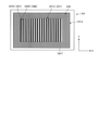
図1は、本実施形態に係る視機能検出装置の一例を模式的に示す斜視図である。視機能検出装置100は、被験者Hを評価する評価装置としても用いられる。図1に示すように、視機能検出装置100は、表示装置101と、ステレオカメラ装置102と、照明装置103とを備える。
(Visual function detection device)
FIG. 1 is a perspective view schematically showing an example of a visual function detection device according to the present embodiment. The visual function detection device 100 is also used as an evaluation device for evaluating the subject H. As shown in FIG. 1, the visual function detection device 100 includes a display device 101, a stereo camera device 102, and a lighting device 103.

表示部としての表示装置101は、液晶ディスプレイ(liquid crystal display:LCD)又は有機ELディスプレイ(organic electroluminescence display:OLED)のようなフラットパネルディスプレイを含む。本実施形態において、表示装置101は、表示画面101Sを有する。表示画面101Sは、画像を表示する。表示画面101Sは、XY平面と実質的に平行である。X軸方向は表示画面101Sの左右方向であり、Y軸方向は表示画面101Sの上下方向であり、Z軸方向は表示画面101Sと直交する奥行方向である。 The display device 101 as a display unit includes a flat panel display such as a liquid crystal display (LCD) or an organic electroluminescence display (OLED). In the present embodiment, the display device 101 has a display screen 101S. The display screen 101S displays an image. The display screen 101S is substantially parallel to the XY plane. The X-axis direction is the left-right direction of the display screen 101S, the Y-axis direction is the vertical direction of the display screen 101S, and the Z-axis direction is the depth direction orthogonal to the display screen 101S.

ステレオカメラ装置102は、第1カメラ102A及び第2カメラ102Bを有する。ステレオカメラ装置102は、表示装置101の表示画面101Sよりも下方に配置される。第1カメラ102Aと第2カメラ102BとはX軸方向に配置される。第1カメラ102Aは、第2カメラ102Bよりも−X方向に配置される。第1カメラ102A及び第2カメラ102Bはそれぞれ、赤外線カメラを含み、例えば波長850[nm]の近赤外光を透過可能な光学系と、その近赤外光を受光可能な撮像素子とを有する。 The stereo camera device 102 has a first camera 102A and a second camera 102B. The stereo camera device 102 is arranged below the display screen 101S of the display device 101. The first camera 102A and the second camera 102B are arranged in the X-axis direction. The first camera 102A is arranged in the −X direction with respect to the second camera 102B. Each of the first camera 102A and the second camera 102B includes an infrared camera, and has, for example, an optical system capable of transmitting near-infrared light having a wavelength of 850 [nm] and an imaging element capable of receiving the near-infrared light. ..

照明装置103は、第1光源103A及び第2光源103Bを有する。照明装置103は、表示装置101の表示画面101Sよりも下方に配置される。第1光源103Aと第2光源103BとはX軸方向に配置される。第1光源103Aは、第1カメラ102Aよりも−X方向に配置される。第2光源103Bは、第2カメラ102Bよりも+X方向に配置される。第1光源103A及び第2光源103Bはそれぞれ、LED(light emitting diode)光源を含み、例えば波長850[nm]の近赤外光を射出可能である。なお、第1光源103A及び第2光源103Bは、第1カメラ102Aと第2カメラ102Bとの間に配置されてもよい。 The lighting device 103 has a first light source 103A and a second light source 103B. The lighting device 103 is arranged below the display screen 101S of the display device 101. The first light source 103A and the second light source 103B are arranged in the X-axis direction. The first light source 103A is arranged in the −X direction with respect to the first camera 102A. The second light source 103B is arranged in the + X direction with respect to the second camera 102B. The first light source 103A and the second light source 103B each include an LED (light emitting diode) light source, and can emit near-infrared light having a wavelength of, for example, 850 [nm]. The first light source 103A and the second light source 103B may be arranged between the first camera 102A and the second camera 102B.

照明装置103は、検出光である近赤外光を射出して、被験者Hの眼球111を照明する。ステレオカメラ装置102は、第1光源103Aから射出された検出光が眼球111に照射されたときに第2カメラ102Bで眼球111を撮影し、第2光源103Bから射出された検出光が眼球111に照射されたときに第1カメラ102Aで眼球111を撮影する。 The illuminating device 103 emits near-infrared light, which is the detection light, to illuminate the eyeball 111 of the subject H. The stereo camera device 102 photographs the eyeball 111 with the second camera 102B when the detection light emitted from the first light source 103A irradiates the eyeball 111, and the detection light emitted from the second light source 103B is emitted to the eyeball 111. When irradiated, the eyeball 111 is photographed by the first camera 102A.

第1カメラ102A及び第2カメラ102Bの少なくとも一方からフレーム同期信号が出力される。第1光源103A及び第2光源103Bは、フレーム同期信号に基づいて検出光を射出する。第1カメラ102Aは、第2光源103Bから射出された検出光が眼球111に照射されたときに、眼球111の画像データを取得する。第2カメラ102Bは、第1光源103Aから射出された検出光が眼球111に照射されたときに、眼球111の画像データを取得する。 A frame synchronization signal is output from at least one of the first camera 102A and the second camera 102B. The first light source 103A and the second light source 103B emit detection light based on the frame synchronization signal. The first camera 102A acquires the image data of the eyeball 111 when the detection light emitted from the second light source 103B irradiates the eyeball 111. The second camera 102B acquires the image data of the eyeball 111 when the detection light emitted from the first light source 103A irradiates the eyeball 111.

眼球111に検出光が照射されると、その検出光の一部は瞳孔112で反射し、その瞳孔112からの光がステレオカメラ装置102に入射する。また、眼球111に検出光が照射されると、角膜の虚像である角膜反射像113が眼球111に形成され、その角膜反射像113からの光がステレオカメラ装置102に入射する。 When the eyeball 111 is irradiated with the detection light, a part of the detection light is reflected by the pupil 112, and the light from the pupil 112 is incident on the stereo camera device 102. When the eyeball 111 is irradiated with the detection light, a corneal reflex image 113, which is a virtual image of the cornea, is formed on the eyeball 111, and the light from the corneal reflex image 113 is incident on the stereo camera device 102.

第1カメラ102A及び第2カメラ102Bと第1光源103A及び第2光源103Bとの相対位置が適切に設定されることにより、瞳孔112からステレオカメラ装置102に入射する光の強度は低くなり、角膜反射像113からステレオカメラ装置102に入射する光の強度は高くなる。すなわち、ステレオカメラ装置102で取得される瞳孔112の画像は低輝度となり、角膜反射像113の画像は高輝度となる。ステレオカメラ装置102は、取得される画像の輝度に基づいて、瞳孔112の位置及び角膜反射像113の位置を検出することができる。 By appropriately setting the relative positions of the first camera 102A and the second camera 102B and the first light source 103A and the second light source 103B, the intensity of the light incident on the stereo camera device 102 from the pupil 112 becomes low, and the corneal membrane The intensity of the light incident on the stereo camera device 102 from the reflected image 113 is increased. That is, the image of the pupil 112 acquired by the stereo camera device 102 has low brightness, and the image of the corneal reflex image 113 has high brightness. The stereo camera device 102 can detect the position of the pupil 112 and the position of the corneal reflex image 113 based on the brightness of the acquired image.

図2は、本実施形態に係る視機能検出装置100のハードウェア構成の一例を示す図である。図2に示すように、視機能検出装置100は、表示装置101と、ステレオカメラ装置102と、照明装置103と、コンピュータシステム20と、入出力インターフェース装置30と、駆動回路40と、出力装置50と、入力装置60とを備える。 FIG. 2 is a diagram showing an example of the hardware configuration of the visual function detection device 100 according to the present embodiment. As shown in FIG. 2, the visual function detection device 100 includes a display device 101, a stereo camera device 102, a lighting device 103, a computer system 20, an input / output interface device 30, a drive circuit 40, and an output device 50. And an input device 60.

コンピュータシステム20と、駆動回路40と、出力装置50と、入力装置60とは、入出力インターフェース装置30を介してデータ通信する。コンピュータシステム20は、演算処理装置20A及び記憶装置20Bを含む。演算処理装置20Aは、CPU(central processing unit)のようなマイクロプロセッサを含む。記憶装置20Bは、ROM(read only memory)及びRAM(random access memory)のようなメモリ又はストレージを含む。演算処理装置20Aは、記憶装置20Bに記憶されているコンピュータプログラム20Cに従って演算処理を実施する。演算処理装置20Aは、記憶装置20Bに記憶されているコンピュータプログラム20Cを実行して視線検出処理を実行するため、本実施形態に係る視線検出装置であるともいえる。 The computer system 20, the drive circuit 40, the output device 50, and the input device 60 communicate data via the input / output interface device 30. The computer system 20 includes an arithmetic processing unit 20A and a storage device 20B. The arithmetic processing device 20A includes a microprocessor such as a CPU (central processing unit). The storage device 20B includes a memory or storage such as a ROM (read only memory) and a RAM (random access memory). The arithmetic processing unit 20A performs arithmetic processing according to the computer program 20C stored in the storage device 20B. Since the arithmetic processing unit 20A executes the computer program 20C stored in the storage device 20B to execute the line-of-sight detection process, it can be said to be the line-of-sight detection device according to the present embodiment.

駆動回路40は、駆動信号を生成して、表示装置101、ステレオカメラ装置102、及び照明装置103に出力する。また、駆動回路40は、ステレオカメラ装置102で取得された眼球111の画像データを、入出力インターフェース装置30を介してコンピュータシステム20に供給する。 The drive circuit 40 generates a drive signal and outputs it to the display device 101, the stereo camera device 102, and the lighting device 103. Further, the drive circuit 40 supplies the image data of the eyeball 111 acquired by the stereo camera device 102 to the computer system 20 via the input / output interface device 30.

出力装置50は、フラットパネルディスプレイのような表示装置を含む。なお、出力装置50は、印刷装置を含んでもよい。入力装置60は、操作されることにより入力データを生成する。入力装置60は、コンピュータシステム用のキーボード又はマウスを含む。なお、入力装置60が表示装置である出力装置50の表示画面に設けられたタッチセンサを含んでもよい。 The output device 50 includes a display device such as a flat panel display. The output device 50 may include a printing device. The input device 60 generates input data by being operated. The input device 60 includes a keyboard or mouse for a computer system. The input device 60 may include a touch sensor provided on the display screen of the output device 50, which is a display device.

本実施形態においては、表示装置101とコンピュータシステム20とは別々の装置である。なお、表示装置101とコンピュータシステム20とが一体でもよい。例えば視機能検出装置100がタブレット型パーソナルコンピュータを含む場合、そのタブレット型パーソナルコンピュータに、コンピュータシステム20、入出力インターフェース装置30、駆動回路40、及び表示装置101が搭載されてもよい。 In the present embodiment, the display device 101 and the computer system 20 are separate devices. The display device 101 and the computer system 20 may be integrated. For example, when the visual function detection device 100 includes a tablet-type personal computer, the tablet-type personal computer may be equipped with a computer system 20, an input / output interface device 30, a drive circuit 40, and a display device 101.

図3は、本実施形態に係る視機能検出装置100の一例を示す機能ブロック図である。図3に示すように、入出力インターフェース装置30は、入出力部302を有する。駆動回路40は、表示装置101を駆動するための駆動信号を生成して表示装置101に出力する表示装置駆動部402と、第1カメラ102Aを駆動するための駆動信号を生成して第1カメラ102Aに出力する第1カメラ入出力部404Aと、第2カメラ102Bを駆動するための駆動信号を生成して第2カメラ102Bに出力する第2カメラ入出力部404Bと、第1光源103A及び第2光源103Bを駆動するための駆動信号を生成して第1光源103A及び第2光源103Bに出力する光源駆動部406とを有する。また、第1カメラ入出力部404Aは、第1カメラ102Aで取得された眼球111の画像データを、入出力部302を介してコンピュータシステム20に供給する。第2カメラ入出力部404Bは、第2カメラ102Bで取得された眼球111の画像データを、入出力部302を介してコンピュータシステム20に供給する。 FIG. 3 is a functional block diagram showing an example of the visual function detecting device 100 according to the present embodiment. As shown in FIG. 3, the input / output interface device 30 has an input / output unit 302. The drive circuit 40 generates a display device drive unit 402 that generates a drive signal for driving the display device 101 and outputs the drive signal to the display device 101, and a first camera that generates a drive signal for driving the first camera 102A. The first camera input / output unit 404A that outputs to 102A, the second camera input / output unit 404B that generates a drive signal for driving the second camera 102B and outputs it to the second camera 102B, the first light source 103A, and the first light source 103A. It has a light source driving unit 406 that generates a drive signal for driving the two light source 103B and outputs the drive signal to the first light source 103A and the second light source 103B. Further, the first camera input / output unit 404A supplies the image data of the eyeball 111 acquired by the first camera 102A to the computer system 20 via the input / output unit 302. The second camera input / output unit 404B supplies the image data of the eyeball 111 acquired by the second camera 102B to the computer system 20 via the input / output unit 302.

コンピュータシステム20は、視機能検出装置100を制御する。コンピュータシステム20は、光源制御部204と、画像データ取得部206と、入力データ取得部208と、位置検出部210と、曲率中心算出部212と、注視点検出部214と、表示制御部216と、関係検出部218と、視機能検出部220と、記憶部222とを有する。コンピュータシステム20の機能は、演算処理装置20A及び記憶装置20Bによって発揮される。 The computer system 20 controls the visual function detection device 100. The computer system 20 includes a light source control unit 204, an image data acquisition unit 206, an input data acquisition unit 208, a position detection unit 210, a curvature center calculation unit 212, a gazing point detection unit 214, and a display control unit 216. , The relationship detection unit 218, the visual function detection unit 220, and the storage unit 222. The functions of the computer system 20 are exhibited by the arithmetic processing unit 20A and the storage device 20B.

光源制御部204は、光源駆動部406を制御して、第1光源103A及び第2光源103Bの作動状態を制御する。光源制御部204は、第1光源103Aと第2光源103Bとが異なるタイミングで検出光を射出するように第1光源103A及び第2光源103Bを制御する。 The light source control unit 204 controls the light source drive unit 406 to control the operating states of the first light source 103A and the second light source 103B. The light source control unit 204 controls the first light source 103A and the second light source 103B so that the first light source 103A and the second light source 103B emit the detected light at different timings.

画像データ取得部206は、第1カメラ102A及び第2カメラ102Bを含むステレオカメラ装置102によって取得された被験者の眼球111の画像データを、入出力部302を介してステレオカメラ装置102から取得する。 The image data acquisition unit 206 acquires image data of the subject's eyeball 111 acquired by the stereo camera device 102 including the first camera 102A and the second camera 102B from the stereo camera device 102 via the input / output unit 302.

入力データ取得部208は、入力装置60が操作されることにより生成された入力データを、入出力部302を介して入力装置60から取得する。 The input data acquisition unit 208 acquires the input data generated by operating the input device 60 from the input device 60 via the input / output unit 302.

位置検出部210は、画像データ取得部206で取得された眼球111の画像データに基づいて、瞳孔中心の位置データを検出する。また、位置検出部210は、画像データ取得部206で取得された眼球111の画像データに基づいて、角膜反射中心の位置データを検出する。瞳孔中心は、瞳孔112の中心である。角膜反射中心は、角膜反射像113の中心である。位置検出部210は、被験者の左右それぞれの眼球111について、瞳孔中心の位置データ及び角膜反射中心の位置データを検出する。 The position detection unit 210 detects the position data at the center of the pupil based on the image data of the eyeball 111 acquired by the image data acquisition unit 206. Further, the position detection unit 210 detects the position data of the corneal reflex center based on the image data of the eyeball 111 acquired by the image data acquisition unit 206. The center of the pupil is the center of the pupil 112. The corneal reflex center is the center of the corneal reflex image 113. The position detection unit 210 detects the position data of the center of the pupil and the position data of the center of the corneal reflex for each of the left and right eyeballs 111 of the subject.

曲率中心算出部212は、画像データ取得部206で取得された眼球111の画像データに基づいて、眼球111の角膜曲率中心の位置データを算出する。 The curvature center calculation unit 212 calculates the position data of the corneal curvature center of the eyeball 111 based on the image data of the eyeball 111 acquired by the image data acquisition unit 206.

注視点検出部214は、画像データ取得部206で取得された眼球111の画像データに基づいて、被験者の注視点の位置データを検出する。本実施形態において、注視点の位置データとは、三次元グローバル座標系で規定される被験者の視線ベクトルと表示装置101の表示画面101Sとの交点の位置データをいう。注視点検出部214は、眼球111の画像データから取得された瞳孔中心の位置データ及び角膜曲率中心の位置データに基づいて、被験者の左右それぞれの眼球111の視線ベクトルを検出する。視線ベクトルが検出された後、注視点検出部214は、視線ベクトルと表示画面101Sとの交点を示す注視点の位置データを検出する。 The gazing point detection unit 214 detects the position data of the gazing point of the subject based on the image data of the eyeball 111 acquired by the image data acquisition unit 206. In the present embodiment, the gazing point position data refers to the position data of the intersection of the subject's line-of-sight vector defined by the three-dimensional global coordinate system and the display screen 101S of the display device 101. The gazing point detection unit 214 detects the line-of-sight vectors of the left and right eyeballs 111 of the subject based on the position data of the center of the pupil and the position data of the center of curvature of the cornea acquired from the image data of the eyeballs 111. After the line-of-sight vector is detected, the gaze point detection unit 214 detects the position data of the gaze point indicating the intersection of the line-of-sight vector and the display screen 101S.

表示制御部216は、表示装置101及び出力装置50の少なくとも1つにデータを出力する。本実施形態において、表示制御部216は、表示装置101に判断用画像231を表示させるためのデータを表示装置101に出力して、表示装置101の表示画面101S上に、判断用画像231を表示させる。表示制御部216が表示させる判断用画像231については、後述する。また、表示制御部216は、被験者Hの左右それぞれの眼球111の注視点の位置を表示画面101S又は出力装置50に表示させてもよい。 The display control unit 216 outputs data to at least one of the display device 101 and the output device 50. In the present embodiment, the display control unit 216 outputs data for displaying the judgment image 231 on the display device 101 to the display device 101, and displays the judgment image 231 on the display screen 101S of the display device 101. Let me. The determination image 231 displayed by the display control unit 216 will be described later. Further, the display control unit 216 may display the positions of the gazing points of the left and right eyeballs 111 of the subject H on the display screen 101S or the output device 50.

関係検出部218は、表示画面101S上の判断用画像231の動く方向と、注視点検出部214が検出した注視点の動く方向との関係を示す情報である関係情報を検出する。関係情報の検出方法については後述する。 The relationship detection unit 218 detects the relationship information, which is information indicating the relationship between the moving direction of the judgment image 231 on the display screen 101S and the moving direction of the gazing point detected by the gazing point detecting unit 214. The method of detecting the related information will be described later.

視機能検出部220は、関係検出部218が検出した関係情報に基づき、被験者Hの視機能を検出する。視機能検出部220は、関係情報に基づき、判断用画像231が被験者Hに見えているかを判定するための基準となる情報を導出することで、視機能を検出する。すなわち、ここで視機能を検出するというのは、判断用画像231が視認可能であるかという判定の基準となる情報を導出することであるといえる。また、視機能検出部220は、判断用画像231が被験者Hに見えているかの判定に基づき、被験者の視力を判定するための基準となる情報を導出してもよいし、例えば白内障であるかを判定するための基準となる情報を導出してもよい。 The visual function detection unit 220 detects the visual function of the subject H based on the relationship information detected by the relationship detection unit 218. The visual function detection unit 220 detects the visual function by deriving information that serves as a reference for determining whether the determination image 231 is visible to the subject H based on the related information. That is, it can be said that detecting the visual function here means deriving information that serves as a reference for determining whether the determination image 231 is visible. Further, the visual function detection unit 220 may derive information as a reference for determining the visual acuity of the subject based on the determination of whether the determination image 231 is visible to the subject H, and may, for example, be a cataract. Information that serves as a reference for determining the above may be derived.

記憶部222は、画像データ取得部206が取得した被験者Hの眼球111の画像データ、注視点検出部214が検出した注視点の位置データ、表示画面101Sに表示させる画像(例えば判断用画像231)の画像データ、関係検出部218が検出した関係情報、及び視機能検出部220による視機能の検出結果のデータなどを記憶する。 The storage unit 222 includes image data of the eyeball 111 of the subject H acquired by the image data acquisition unit 206, position data of the gazing point detected by the gazing point detecting unit 214, and an image to be displayed on the display screen 101S (for example, a determination image 231). The image data of the above, the relationship information detected by the relationship detection unit 218, the data of the detection result of the visual function by the visual function detection unit 220, and the like are stored.

記憶部222は、表示画面101Sに画像を表示させる処理と、表示画面101Sを観察する被験者Hの注視点の位置を検出する処理と、判断用画像231の動く方向と注視点の動く方向との関係情報を検出する処理と、情報に基づき視機能を検出する処理とをコンピュータに実行させるプログラムを記憶する。 The storage unit 222 includes a process of displaying an image on the display screen 101S, a process of detecting the position of the gazing point of the subject H observing the display screen 101S, and a moving direction of the determination image 231 and a moving direction of the gazing point. A program that causes a computer to execute a process of detecting related information and a process of detecting a visual function based on the information is stored.

次に、本実施形態に係る曲率中心算出部212の処理の概要について説明する。曲率中心算出部212は、眼球111の画像データに基づいて、眼球111の角膜曲率中心の位置データを算出する。図4及び図5は、本実施形態に係る角膜曲率中心110の位置データの算出方法を説明するための模式図である。図4は、1つの光源103Cで眼球111が照明される例を示す。図5は、第1光源103A及び第2光源103Bで眼球111が照明される例を示す。 Next, an outline of the processing of the curvature center calculation unit 212 according to the present embodiment will be described. The curvature center calculation unit 212 calculates the position data of the corneal curvature center of the eyeball 111 based on the image data of the eyeball 111. 4 and 5 are schematic views for explaining a method of calculating the position data of the corneal curvature center 110 according to the present embodiment. FIG. 4 shows an example in which the eyeball 111 is illuminated by one light source 103C. FIG. 5 shows an example in which the eyeball 111 is illuminated by the first light source 103A and the second light source 103B.

まず、図4に示す例について説明する。光源103Cは、第1カメラ102Aと第2カメラ102Bとの間に配置される。瞳孔中心112Cは、瞳孔112の中心である。角膜反射中心113Cは、角膜反射像113の中心である。図4において、瞳孔中心112Cは、眼球111が1つの光源103Cで照明されたときの瞳孔中心を示す。角膜反射中心113Cは、眼球111が1つの光源103Cで照明されたときの角膜反射中心を示す。角膜反射中心113Cは、光源103Cと角膜曲率中心110とを結ぶ直線上に存在する。角膜反射中心113Cは、角膜表面と角膜曲率中心110との中間点に位置付けられる。角膜曲率半径109は、角膜表面と角膜曲率中心110との距離である。角膜反射中心113Cの位置データは、ステレオカメラ装置102によって検出される。角膜曲率中心110は、光源103Cと角膜反射中心113Cとを結ぶ直線上に存在する。曲率中心算出部212は、その直線上において角膜反射中心113Cからの距離が所定値となる位置データを、角膜曲率中心110の位置データとして算出する。所定値は、一般的な角膜の曲率半径値などから事前に定められた値であり、記憶部222に記憶されている。 First, an example shown in FIG. 4 will be described. The light source 103C is arranged between the first camera 102A and the second camera 102B. The pupil center 112C is the center of the pupil 112. The corneal reflex center 113C is the center of the corneal reflex image 113. In FIG. 4, the pupil center 112C indicates the pupil center when the eyeball 111 is illuminated by one light source 103C. The corneal reflex center 113C indicates the corneal reflex center when the eyeball 111 is illuminated by one light source 103C. The corneal reflex center 113C exists on a straight line connecting the light source 103C and the corneal curvature center 110. The corneal reflex center 113C is positioned at the midpoint between the corneal surface and the corneal curvature center 110. The radius of curvature of the cornea 109 is the distance between the surface of the cornea and the center of curvature of the cornea 110. The position data of the corneal reflex center 113C is detected by the stereo camera device 102. The corneal curvature center 110 exists on a straight line connecting the light source 103C and the corneal reflection center 113C. The curvature center calculation unit 212 calculates the position data in which the distance from the corneal reflection center 113C is a predetermined value on the straight line as the position data of the corneal curvature center 110. The predetermined value is a value predetermined from a general radius of curvature value of the cornea and the like, and is stored in the storage unit 222.

次に、図5に示す例について説明する。本実施形態においては、第1カメラ102A及び第2光源103Bと、第2カメラ102B及び第1光源103Aとは、第1カメラ102Aと第2カメラ102Bとの中間位置を通る直線に対して左右対称の位置に配置される。第1カメラ102Aと第2カメラ102Bとの中間位置に仮想光源103Vが存在するとみなすことができる。角膜反射中心121は、第2カメラ102Bで眼球111を撮影した画像における角膜反射中心を示す。角膜反射中心122は、第1カメラ102Aで眼球111を撮影した画像における角膜反射中心を示す。角膜反射中心124は、仮想光源103Vに対応する角膜反射中心を示す。角膜反射中心124の位置データは、ステレオカメラ装置102で取得された角膜反射中心121の位置データ及び角膜反射中心122の位置データに基づいて算出される。ステレオカメラ装置102は、ステレオカメラ装置102に規定される三次元ローカル座標系において角膜反射中心121の位置データ及び角膜反射中心122の位置データを検出する。ステレオカメラ装置102について、事前にステレオ較正法によるカメラ較正が実施され、ステレオカメラ装置102の三次元ローカル座標系を三次元グローバル座標系に変換する変換パラメータが算出される。その変換パラメータは、記憶部222に記憶されている。曲率中心算出部212は、ステレオカメラ装置102で取得された角膜反射中心121の位置データ及び角膜反射中心122の位置データを、変換パラメータを使って、三次元グローバル座標系における位置データに変換する。曲率中心算出部212は、三次元グローバル座標系で規定される角膜反射中心121の位置データ及び角膜反射中心122の位置データに基づいて、三次元グローバル座標系における角膜反射中心124の位置データを算出する。角膜曲率中心110は、仮想光源103Vと角膜反射中心124とを結ぶ直線123上に存在する。曲率中心算出部212は、直線123上において角膜反射中心124からの距離が所定値となる位置データを、角膜曲率中心110の位置データとして算出する。所定値は、一般的な角膜の曲率半径値などから事前に定められた値であり、記憶部222に記憶されている。 Next, an example shown in FIG. 5 will be described. In the present embodiment, the first camera 102A and the second light source 103B and the second camera 102B and the first light source 103A are symmetrical with respect to a straight line passing through an intermediate position between the first camera 102A and the second camera 102B. Is placed at the position of. It can be considered that the virtual light source 103V exists at an intermediate position between the first camera 102A and the second camera 102B. The corneal reflex center 121 indicates the corneal reflex center in the image of the eyeball 111 taken by the second camera 102B. The corneal reflex center 122 indicates the corneal reflex center in the image of the eyeball 111 taken by the first camera 102A. The corneal reflex center 124 indicates a corneal reflex center corresponding to the virtual light source 103V. The position data of the corneal reflex center 124 is calculated based on the position data of the corneal reflex center 121 and the position data of the corneal reflex center 122 acquired by the stereo camera device 102. The stereo camera device 102 detects the position data of the corneal reflex center 121 and the position data of the corneal reflex center 122 in the three-dimensional local coordinate system defined by the stereo camera device 102. The stereo camera device 102 is calibrated in advance by a stereo calibration method, and conversion parameters for converting the three-dimensional local coordinate system of the stereo camera device 102 into a three-dimensional global coordinate system are calculated. The conversion parameter is stored in the storage unit 222. The curvature center calculation unit 212 converts the position data of the corneal reflex center 121 and the position data of the corneal reflex center 122 acquired by the stereo camera device 102 into position data in the three-dimensional global coordinate system using conversion parameters. The curvature center calculation unit 212 calculates the position data of the corneal reflex center 124 in the three-dimensional global coordinate system based on the position data of the corneal reflex center 121 and the position data of the corneal reflex center 122 defined in the three-dimensional global coordinate system. do. The corneal curvature center 110 exists on a straight line 123 connecting the virtual light source 103V and the corneal reflection center 124. The curvature center calculation unit 212 calculates the position data at which the distance from the corneal reflection center 124 is a predetermined value on the straight line 123 as the position data of the corneal curvature center 110. The predetermined value is a value predetermined from a general radius of curvature value of the cornea and the like, and is stored in the storage unit 222.

このように、光源が2つある場合でも、光源が1つである場合の方法と同様の方法で、角膜曲率中心110が算出される。 In this way, even when there are two light sources, the corneal curvature center 110 is calculated by the same method as when there is one light source.

角膜曲率半径109は、角膜表面と角膜曲率中心110との距離である。したがって、角膜表面の位置データ及び角膜曲率中心110の位置データが算出されることにより、角膜曲率半径109が算出される。 The radius of curvature of the cornea 109 is the distance between the surface of the cornea and the center of curvature of the cornea 110. Therefore, the corneal radius of curvature 109 is calculated by calculating the position data of the corneal surface and the position data of the corneal curvature center 110.

次に、本実施形態に係る視線検出方法の一例について説明する。図6は、本実施形態に係るキャリブレーション処理の一例を説明するための模式図である。キャリブレーション処理では、被験者に注視させるため、目標位置130が設定される。目標位置130は、三次元グローバル座標系において規定される。本実施形態において、目標位置130は、例えば表示装置101の表示画面101Sの中央位置に設定される。なお、目標位置130は、表示画面101Sの端部位置に設定されてもよい。出力制御部226は、設定された目標位置130に目標画像を表示させる。直線131は、仮想光源103Vと角膜反射中心113Cとを結ぶ直線である。直線132は、目標位置130と瞳孔中心112Cとを結ぶ直線である。角膜曲率中心110は、直線131と直線132との交点である。曲率中心算出部212は、仮想光源103Vの位置データと、目標位置130の位置データと、瞳孔中心112Cの位置データと、角膜反射中心113Cの位置データとに基づいて、角膜曲率中心110の位置データを算出することができる。 Next, an example of the line-of-sight detection method according to the present embodiment will be described. FIG. 6 is a schematic diagram for explaining an example of the calibration process according to the present embodiment. In the calibration process, the target position 130 is set so that the subject can gaze. The target position 130 is defined in the three-dimensional global coordinate system. In the present embodiment, the target position 130 is set, for example, at the center position of the display screen 101S of the display device 101. The target position 130 may be set at the end position of the display screen 101S. The output control unit 226 displays the target image at the set target position 130. The straight line 131 is a straight line connecting the virtual light source 103V and the corneal reflection center 113C. The straight line 132 is a straight line connecting the target position 130 and the pupil center 112C. The center of curvature 110 of the cornea is the intersection of the straight line 131 and the straight line 132. The curvature center calculation unit 212 is based on the position data of the virtual light source 103V, the position data of the target position 130, the position data of the pupil center 112C, and the position data of the corneal reflection center 113C, and the position data of the corneal curvature center 110. Can be calculated.

次に、注視点検出処理について説明する。注視点検出処理は、キャリブレーション処理の後に実施される。注視点検出部214は、眼111の画像データに基づいて、被験者の視線ベクトル及び注視点の位置データを算出する。図7は、本実施形態に係る注視点検出処理の一例を説明するための模式図である。図7において、注視点165は、一般的な曲率半径値を用いて算出された角膜曲率中心から求めた注視点を示す。注視点166は、キャリブレーション処理で求められた距離126を用いて算出された角膜曲率中心から求めた注視点を示す。瞳孔中心112Cは、キャリブレーション処理において算出された瞳孔中心を示し、角膜反射中心113Cは、キャリブレーション処理において算出された角膜反射中心を示す。直線173は、仮想光源103Vと角膜反射中心113Cとを結ぶ直線である。角膜曲率中心110は、一般的な曲率半径値から算出した角膜曲率中心の位置である。距離126は、キャリブレーション処理により算出した瞳孔中心112Cと角膜曲率中心110との距離である。角膜曲率中心110Hは、距離126を用いて角膜曲率中心110を補正した補正後の角膜曲率中心の位置を示す。角膜曲率中心110Hは、角膜曲率中心110が直線173上に存在すること、及び瞳孔中心112Cと角膜曲率中心110との距離が距離126であることから求められる。これにより、一般的な曲率半径値を用いる場合に算出される視線177は、視線178に補正される。また、表示装置101の表示画面101S上の注視点は、注視点165から注視点166に補正される。 Next, the gazing point detection process will be described. The gazing point detection process is performed after the calibration process. The gaze point detection unit 214 calculates the gaze vector of the subject and the position data of the gaze point based on the image data of the eye 111. FIG. 7 is a schematic diagram for explaining an example of the gaze point detection process according to the present embodiment. In FIG. 7, the gazing point 165 indicates a gazing point obtained from the center of curvature of the cornea calculated using a general radius of curvature value. The gazing point 166 indicates a gazing point obtained from the center of curvature of the cornea calculated using the distance 126 obtained in the calibration process. The pupil center 112C indicates the pupil center calculated in the calibration process, and the corneal reflex center 113C indicates the corneal reflex center calculated in the calibration process. The straight line 173 is a straight line connecting the virtual light source 103V and the corneal reflection center 113C. The corneal curvature center 110 is the position of the corneal curvature center calculated from a general radius of curvature value. The distance 126 is the distance between the pupil center 112C and the corneal curvature center 110 calculated by the calibration process. The corneal curvature center 110H indicates the position of the corrected corneal curvature center after the corneal curvature center 110 is corrected using the distance 126. The corneal curvature center 110H is obtained because the corneal curvature center 110 exists on the straight line 173 and the distance between the pupil center 112C and the corneal curvature center 110 is 126. As a result, the line-of-sight 177 calculated when a general radius of curvature value is used is corrected to the line-of-sight 178. Further, the gazing point on the display screen 101S of the display device 101 is corrected from the gazing point 165 to the gazing point 166.

(視機能検出方法)
次に、本実施形態に係る視機能検出方法について説明する。図8は、本実施形態に係る判断用画像を示す図である。表示制御部216は、視機能検出を行う際、表示装置101に画像230を表示させるためのデータを表示装置101に出力して、表示装置101の表示画面101S上に、画像230を表示させる。図8に示すように、画像230は、判断用画像231と、背景用画像232とを含む。すなわち、表示制御部216は、表示装置101に判断用画像231を表示させるためのデータと、背景用画像232を表示させるためのデータとを出力して、表示装置101の表示画面101S上に、判断用画像231と背景用画像232とを表示させるといえる。なお、画像230は、表示画面101Sの全域を占める画像であるが、表示画面101Sの一部を占める画像であってもよい。
(Visual function detection method)
Next, the visual function detection method according to the present embodiment will be described. FIG. 8 is a diagram showing a determination image according to the present embodiment. When the visual function detection is performed, the display control unit 216 outputs data for displaying the image 230 on the display device 101 to the display device 101, and displays the image 230 on the display screen 101S of the display device 101. As shown in FIG. 8, the image 230 includes a judgment image 231 and a background image 232. That is, the display control unit 216 outputs data for displaying the judgment image 231 on the display device 101 and data for displaying the background image 232 on the display screen 101S of the display device 101. It can be said that the judgment image 231 and the background image 232 are displayed. Although the image 230 is an image that occupies the entire area of the display screen 101S, it may be an image that occupies a part of the display screen 101S.

図8に示すように、判断用画像231は、画像230が表示される領域(ここでは表示画面101S)内の表示領域101T内に表示される。すなわち、判断用画像231は、表示画面101Sの表示領域101Tの、全域を占めるように表示される。本実施形態では、表示領域101Tは、表示画面101Sの一部の領域である。ただし、表示領域101Tは、表示画面101Sの全域を占めるものであってもよい。この場合、画像230は、背景用画像232を有さず判断用画像231のみを有することとなる。 As shown in FIG. 8, the determination image 231 is displayed in the display area 101T in the area where the image 230 is displayed (here, the display screen 101S). That is, the determination image 231 is displayed so as to occupy the entire display area 101T of the display screen 101S. In the present embodiment, the display area 101T is a part of the display screen 101S. However, the display area 101T may occupy the entire area of the display screen 101S. In this case, the image 230 does not have the background image 232 but has only the judgment image 231.

判断用画像231は、表示画面101Sの1倍以下の大きさであることが好ましい。このようにすることで、被検査者Hは、判断用画像231を適切に視認することができる。 The size of the judgment image 231 is preferably 1 times or less the size of the display screen 101S. By doing so, the inspected person H can appropriately visually recognize the judgment image 231.

判断用画像231は、模様を表示する画像である。具体的には、判断用画像231は、第1画像241と第2画像242とを有する。言い換えれば、表示領域101Tは、第1画像241が表示される第1領域と、第2画像242が表示される第1領域とに区分されている。従って、第1画像241とは、第1画像241が表示される第1領域と言い換えることができ、第2画像242とは、第2画像242が表示される第2領域であると言い換えることができる。第1画像241と第2画像242とは、互いに輝度が異なる画像である。本実施形態において、第1画像241は、第2画像242よりも輝度が低い画像である。また、本実施形態の例では、第1画像241と第2画像242とは、無彩色の画像である。従って、第1画像241は、第2画像242よりも黒成分が強く、第2画像242は、第1画像241よりも白成分が強い。ただし、第1画像241と第2画像242とは、互いに輝度が異なる画像であれば、彩色の画像であってもよい。 The judgment image 231 is an image for displaying a pattern. Specifically, the determination image 231 has a first image 241 and a second image 242. In other words, the display area 101T is divided into a first area in which the first image 241 is displayed and a first area in which the second image 242 is displayed. Therefore, the first image 241 can be rephrased as the first region in which the first image 241 is displayed, and the second image 242 can be rephrased as the second region in which the second image 242 is displayed. can. The first image 241 and the second image 242 are images having different brightnesses from each other. In the present embodiment, the first image 241 is an image having a lower brightness than the second image 242. Further, in the example of the present embodiment, the first image 241 and the second image 242 are achromatic images. Therefore, the first image 241 has a stronger black component than the second image 242, and the second image 242 has a stronger white component than the first image 241. However, the first image 241 and the second image 242 may be colored images as long as they have different brightness.

図8に示すように、本実施形態においては、判断用画像231は、第1画像241と第2画像242とを複数含み、第1画像241と第2画像242とが、交互にストライプ状に配列している。すなわち、第1画像241と第2画像242とは、Y軸方向に沿った長さが、表示領域101TのY軸方向に沿った長さと同じであり、Y軸方向に沿って、表示領域101Tの上端から下端まで延在する。そして、第1画像241と第2画像242とは、X軸方向に沿った長さ(幅)が、表示領域101TのX軸方向に沿った長さより短くなっている。第1画像241と第2画像242とは、表示領域101T内で、X軸方向に沿って交互に並んでいる。なお、本実施形態では、表示領域101TのX軸方向に沿った端面から離れている第1画像241同士は、面積が等しい。同様に、表示領域101TのX軸方向に沿った端面から離れている第2画像242同士も、面積が等しい。そして、表示領域101TのX軸方向に沿った端面から離れている第1画像241と第2画像242とも、面積が等しい。また、第1画像241の数と第2画像242の数も同じである。ただし、第1画像241同士の面積及び形状は互いに異なってもよいし、第2画像242同士の面積及び形状も、互いに異なってよい。そして、第1画像241の数と第2画像242の数とも、異なっていてよい。 As shown in FIG. 8, in the present embodiment, the determination image 231 includes a plurality of the first image 241 and the second image 242, and the first image 241 and the second image 242 are alternately striped. It is arranged. That is, the length of the first image 241 and the second image 242 along the Y-axis direction is the same as the length of the display area 101T along the Y-axis direction, and the display area 101T is along the Y-axis direction. Extends from the top to the bottom of. The length (width) of the first image 241 and the second image 242 along the X-axis direction is shorter than the length of the display area 101T along the X-axis direction. The first image 241 and the second image 242 are alternately arranged in the display area 101T along the X-axis direction. In the present embodiment, the areas of the first images 241 separated from the end faces of the display area 101T along the X-axis direction are the same. Similarly, the areas of the second images 242 that are separated from the end faces of the display area 101T along the X-axis direction are the same. The areas of the first image 241 and the second image 242, which are separated from the end faces of the display area 101T along the X-axis direction, are the same. Further, the number of the first image 241 and the number of the second image 242 are also the same. However, the areas and shapes of the first images 241 may be different from each other, and the areas and shapes of the second images 242 may also be different from each other. The number of the first image 241 and the number of the second image 242 may also be different.

図8に示すように、背景用画像232は、画像230が表示される領域(ここでは表示画面101S)内において、判断用画像231が表示される表示領域101T以外の領域に表示される画像である。すなわち、背景用画像232は、表示領域101T(判断用画像231)の周囲を囲うように表示される画像である。背景用画像232は、画像230が表示される領域のうち、表示領域101T以外の領域の全域を占めるように表示される。ただし、背景用画像232は、表示領域101Tの周囲を囲うものであれば、表示領域101T以外の領域の一部を占めるものであってもよい。 As shown in FIG. 8, the background image 232 is an image displayed in an area other than the display area 101T in which the judgment image 231 is displayed in the area where the image 230 is displayed (here, the display screen 101S). be. That is, the background image 232 is an image displayed so as to surround the display area 101T (judgment image 231). The background image 232 is displayed so as to occupy the entire area other than the display area 101T in the area where the image 230 is displayed. However, the background image 232 may occupy a part of the area other than the display area 101T as long as it surrounds the display area 101T.

また、判断用画像231は、模様がない一様な画像である。本実施形態において、背景用画像232は、全域において輝度が一定の画像であり、さらに言えば、判断用画像231と同じ彩色、すなわち無彩色の画像である。従って、背景用画像232は、第1画像241よりも、輝度が大きく、白色成分が高い。そして、背景用画像232は、第2画像242よりも、輝度が小さく、黒色成分が高い。 Further, the judgment image 231 is a uniform image without a pattern. In the present embodiment, the background image 232 is an image having a constant brightness over the entire area, and more specifically, is an image having the same color as the judgment image 231, that is, an achromatic image. Therefore, the background image 232 has a higher brightness and a higher white component than the first image 241. The background image 232 has a lower brightness and a higher black component than the second image 242.

図9は、判断用画像が移動する様子を示す図である。表示制御部216は、表示領域101T内で、判断用画像231を、X軸方向に移動させる。表示制御部216は、表示領域101Tの位置を固定させたまま、表示領域101T内で、判断用画像231をX軸方向に動かす。すなわち、判断用画像231は、表示領域101T内で表示される動画像であるといえる。判断用画像231を動かす方向は、X軸方向に限られず任意であり、予め定めた一方向である所定方向であればよい。この所定方向は、本実施形態のように、第1画像241と第2画像242とが並ぶ方向であることが好ましいが、それに限られない。また、表示制御部231は、また、判断用画像231を動かす方向を、所定方向に限られずに、任意の方向に動かしてよい。すなわち、表示制御部231は、判断用画像231を、表示領域101Tで動かすものであればよい。また、表示制御部216は、判断用画像231を動かす方向を、途中で切り替えないことが好ましい。また、表示制御部216は、表示領域101Tの位置を動かしてもよい。 FIG. 9 is a diagram showing how the judgment image moves. The display control unit 216 moves the determination image 231 in the X-axis direction within the display area 101T. The display control unit 216 moves the determination image 231 in the X-axis direction within the display area 101T while fixing the position of the display area 101T. That is, it can be said that the determination image 231 is a moving image displayed in the display area 101T. The direction in which the determination image 231 is moved is not limited to the X-axis direction, and may be any predetermined direction, which is a predetermined direction. This predetermined direction is preferably, but is not limited to, the direction in which the first image 241 and the second image 242 are arranged side by side as in the present embodiment. Further, the display control unit 231 may move the determination image 231 in any direction without being limited to a predetermined direction. That is, the display control unit 231 may move the determination image 231 in the display area 101T. Further, it is preferable that the display control unit 216 does not switch the direction in which the determination image 231 is moved in the middle. Further, the display control unit 216 may move the position of the display area 101T.

より詳しくは、表示制御部216は、判断用画像231、すなわち第1画像241と第2画像242とを、X軸方向に沿ってスクロールさせる。言い換えれば、表示制御部216は、複数の判断用画像231を予め準備する。それらの判断用画像231は、第1画像241と第2画像242との表示位置が、X軸方向に沿って互いにずれた画像(例えば図9の状態S1からS4の画像)である。そして、表示制御部216は、フレーム毎に、これらの判断用画像231を順番に表示する。これにより、判断用画像231は、第1画像241と第2画像242とをX軸方向に沿ってスクロールされた動画像となるように視認される。この場合、第1画像241と第2画像242とは、時間経過に伴い、表示領域101T内をX軸方向に移動し、表示領域101TのX軸方向側の端部に到達したら徐々に面積が小さくなり、表示領域101Tから消える。そして、X軸方向と反対側の端部からは、第1画像241と第2画像242が順次現れ、所定面積に達したら、X軸方向に移動する。 More specifically, the display control unit 216 scrolls the determination image 231, that is, the first image 241 and the second image 242 along the X-axis direction. In other words, the display control unit 216 prepares a plurality of determination images 231 in advance. The determination image 231 is an image in which the display positions of the first image 241 and the second image 242 are deviated from each other along the X-axis direction (for example, the images of the states S1 to S4 in FIG. 9). Then, the display control unit 216 displays these determination images 231 in order for each frame. As a result, the determination image 231 is visually recognized as a moving image in which the first image 241 and the second image 242 are scrolled along the X-axis direction. In this case, the first image 241 and the second image 242 move in the display area 101T in the X-axis direction with the passage of time, and when they reach the end of the display area 101T on the X-axis direction, the area gradually increases. It becomes smaller and disappears from the display area 101T. Then, the first image 241 and the second image 242 appear in sequence from the end opposite to the X-axis direction, and when the predetermined area is reached, the first image 241 and the second image 242 move in the X-axis direction.

さらに詳しく説明すると、図9に示すように、複数の第2画像242のうちの1つである第2画像242Sについて着目する。第2画像242Sは、時間経過と共に、表示領域101T内をX軸方向に移動し、第2画像242SのX軸方向の端部(図9の例では右側の端部)に到達する(図9の状態S1)。その後、第2画像242Sは、X軸方向の端部で面積が徐々に小さくなり(図9の状態S2)、さらに時間が経過すると、表示領域101Tから消える(図9の状態S3)。そして、その第2画像242の移動中、表示領域101TのX軸方向と反対側の端部(図9の例では左側の端部)では、別の第2画像242Tが、X軸方向側に徐々に面積を大きくしながら現れ(状態S2)、規定の面積に達したら(状態S3)、その面積のまま表示領域101T内をX軸方向に移動する(状態S4)。第1画像241も、第2画像242S、242Tと同様に移動する。判断用画像231は、この状態S4に達したら、状態S1に戻り、同じ動きを繰り返す。すなわち、表示制御部216が判断用画像231をX軸方向に移動させている間中、判断用画像231は、このような動きを繰り返す。 More specifically, as shown in FIG. 9, attention is paid to the second image 242S, which is one of the plurality of second images 242. The second image 242S moves in the display area 101T in the X-axis direction with the passage of time, and reaches the end of the second image 242S in the X-axis direction (the right end in the example of FIG. 9) (FIG. 9). State S1). After that, the area of the second image 242S gradually decreases at the end in the X-axis direction (state S2 in FIG. 9), and disappears from the display area 101T after a further lapse of time (state S3 in FIG. 9). Then, while the second image 242 is moving, another second image 242T is moved to the X-axis direction side at the end portion of the display area 101T opposite to the X-axis direction (the left end portion in the example of FIG. 9). It appears while gradually increasing the area (state S2), and when it reaches the specified area (state S3), it moves in the display area 101T in the X-axis direction with the area as it is (state S4). The first image 241 also moves in the same manner as the second image 242S and 242T. When the determination image 231 reaches this state S4, it returns to the state S1 and repeats the same movement. That is, while the display control unit 216 moves the determination image 231 in the X-axis direction, the determination image 231 repeats such a movement.

表示制御部216は、予め定めた速度で、フレーム毎に、判断用画像231を移動させる。移動速度は、100ピクセル/秒以上400ピクセル/秒以下程度であるが、それに限られず任意に設定可能である。 The display control unit 216 moves the determination image 231 for each frame at a predetermined speed. The moving speed is about 100 pixels / sec or more and 400 pixels / sec or less, but is not limited to this and can be set arbitrarily.

図10から図12は、異なるパターンの判断用画像を説明した図である。表示制御部216は、視機能検出検査のために、例えば図10から図12に示すように、異なるパターンの判断用画像231を表示する場合がある。表示制御部216は、いずれかのパターンの判断用画像231を選択して、選択したパターンの判断用画像231を、上記のように動かす。 10 to 12 are diagrams illustrating images for determining different patterns. The display control unit 216 may display different patterns of determination images 231 for visual function detection inspection, for example, as shown in FIGS. 10 to 12. The display control unit 216 selects the judgment image 231 of any pattern, and moves the judgment image 231 of the selected pattern as described above.

図10に示す判断用画像231Aと、図11に示す判断用画像231Bと、図12に示す判断用画像231Cとは、第1画像241及び第2画像242の大きさ(面積)が、互いに異なり、第1画像241及び第2画像242の数も、互いに異なる。すなわち、判断用画像231A、231B、231Cは、第1画像241及び第2画像242の粗密分布が互いに異なる。一方、判断用画像231Aと判断用画像231Bと判断用画像231Cとは、全体の大きさ、すなわち表示領域101Tの大きさが、互いに等しいが、大きさが互いに異なってもよい。 The judgment image 231A shown in FIG. 10, the judgment image 231B shown in FIG. 11, and the judgment image 231C shown in FIG. 12 have different sizes (areas) of the first image 241 and the second image 242. , The numbers of the first image 241 and the second image 242 are also different from each other. That is, the judgment images 231A, 231B, and 231C have different density distributions of the first image 241 and the second image 242. On the other hand, the judgment image 231A, the judgment image 231B, and the judgment image 231C have the same overall size, that is, the size of the display area 101T, but the sizes may be different from each other.

図10から図12の例では、判断用画像231Bの第1画像241B及び第2画像242Bは、判断用画像231Aの第1画像241A及び第2画像242Aよりも、面積が小さい。さらに言えば、第1画像241Bと第2画像242Bとの方向Xに沿った長さは、第1画像241Aと第2画像242Aとの方向Xに沿った長さよりも短い。また、判断用画像231Bは、第1画像241B及び第2画像242Bの数が、判断用画像231Aの第1画像241A及び第2画像242Aよりも多い。そして、判断用画像231Cの第1画像241C及び第2画像242Cは、判断用画像231Bの第1画像241B及び第2画像242Bよりも、面積が小さい。さらに言えば、第1画像241Cと第2画像242Cとの方向Xに沿った長さは、第1画像241Bと第2画像242Bとの方向Xに沿った長さよりも短い。また、判断用画像231Cは、第1画像241C及び第2画像242Cの数が、判断用画像231Bの第1画像241B及び第2画像242Bよりも多い。 In the example of FIGS. 10 to 12, the first image 241B and the second image 242B of the judgment image 231B have a smaller area than the first image 241A and the second image 242A of the judgment image 231A. Furthermore, the length of the first image 241B and the second image 242B along the direction X is shorter than the length of the first image 241A and the second image 242A along the direction X. Further, in the judgment image 231B, the number of the first image 241B and the second image 242B is larger than that of the first image 241A and the second image 242A of the judgment image 231A. The first image 241C and the second image 242C of the judgment image 231C have a smaller area than the first image 241B and the second image 242B of the judgment image 231B. Furthermore, the length of the first image 241C and the second image 242C along the direction X is shorter than the length of the first image 241B and the second image 242B along the direction X. Further, in the judgment image 231C, the number of the first image 241C and the second image 242C is larger than that of the first image 241B and the second image 242B of the judgment image 231B.

図11に示す判断用画像231Bは、第1画像241と第2画像242とが、図10に示す判断用画像231Aより小さいため、判断用画像231Aよりも、被験者に視認され難い。同様に、図11に示す判断用画像231Cは、判断用画像231Bよりも、被験者に視認され難い。従って、表示制御部216は、このように異なるパターンの判断用画像231を表示させることで、被験者Hの視機能の度合い(例えば視力など)を、段階的に検出することができる。 In the judgment image 231B shown in FIG. 11, since the first image 241 and the second image 242 are smaller than the judgment image 231A shown in FIG. 10, they are less likely to be visually recognized by the subject than the judgment image 231A. Similarly, the judgment image 231C shown in FIG. 11 is less likely to be visually recognized by the subject than the judgment image 231B. Therefore, the display control unit 216 can detect the degree of visual acuity (for example, visual acuity) of the subject H step by step by displaying the judgment images 231 having different patterns in this way.

表示制御部216は、視機能検出を行う際、このようにして、表示装置101の表示画面101Sに判断用画像231と背景用画像232とを表示させる。被験者Hは、視機能検出の際、表示画面101Sを観察しており、注視点検出部214は、その時の被験者Hの注視点166を検出する。関係検出部218は、表示画面101S上の判断用画像231の移動方向と、注視点検出部214が検出した注視点の移動方向との関係を示す関係情報を検出し、視機能検出部220は、その関係情報に基づき、被験者Hの視機能を検出する。以下、視機能を検出するフローについて、説明する。 When the visual function is detected, the display control unit 216 causes the display screen 101S of the display device 101 to display the judgment image 231 and the background image 232 in this way. The subject H is observing the display screen 101S at the time of detecting the visual function, and the gazing point detection unit 214 detects the gazing point 166 of the subject H at that time. The relationship detection unit 218 detects the relationship information indicating the relationship between the moving direction of the judgment image 231 on the display screen 101S and the moving direction of the gazing point detected by the gazing point detecting unit 214, and the visual function detecting unit 220 detects the relationship information. , The visual function of subject H is detected based on the related information. Hereinafter, the flow for detecting the visual function will be described.

図13は、視機能を検出するフローを説明するフローチャートである。図14は、注視点の位置の例を説明する図である。図13に示すように、視機能検出を行う場合、注視点検出部214は、上述した注視点検出処理を実行して(ステップS10)、表示画面101Sの前に位置する被験者Hの注視点166の位置を検出する。被験者の眼球111の画像データは、画像データ取得部206の撮像により、所定時間毎に取得される。従って、注視点検出部214は、所定時間毎に、注視点166の位置を検出する。この所定時間は、例えば1/60秒程度であるため、注視点166は、1秒間に60回程度検出される。ただし、この所定時間の長さは任意である。注視点検出部214は、後述する判断用画像231が表示される期間中、注視点166の位置検出を続ける。 FIG. 13 is a flowchart illustrating a flow for detecting the visual function. FIG. 14 is a diagram illustrating an example of the position of the gazing point. As shown in FIG. 13, when performing visual function detection, the gaze point detection unit 214 executes the gaze point detection process described above (step S10), and the gaze point 166 of the subject H located in front of the display screen 101S. Detect the position of. The image data of the subject's eyeball 111 is acquired at predetermined time intervals by imaging by the image data acquisition unit 206. Therefore, the gazing point detection unit 214 detects the position of the gazing point 166 at predetermined time intervals. Since this predetermined time is, for example, about 1/60 second, the gazing point 166 is detected about 60 times per second. However, the length of this predetermined time is arbitrary. The gazing point detection unit 214 continues to detect the position of the gazing point 166 during the period when the determination image 231 described later is displayed.

そして、視機能検出装置100は、表示制御部216により、表示領域101Tに判断用画像231を表示させ、判断用画像231を、表示領域101T内でスクロール(移動)させる(ステップS12)。すなわち、表示制御部216は、表示領域101T内でスクロールさせつつ、判断用画像231を表示させ続ける。そして、視機能検出装置100は、検出時間と算出結果とをリセットして(ステップS14)、注視点166の位置検出結果を取得する(ステップS16)。検出時間とは、予め定められた時間であり、判断用画像231を表示して注視点検出を行う期間である。検出時間は、例えば20秒程度であるが、時間は任意である。視機能検出装置100は、検出時間をリセットして判断用画像231の表示と注視点検出とを開始させ、開始させたタイミングからの時間のカウントを始める。算出結果とは、後述する合計移動距離などの算出結果である。すなわち、算出結果をリセットするとは、積算していた合計移動距離の値をゼロとすることであり、視機能検出装置100は、このタイミングから合計移動距離の算出を開始する。また、視機能検出装置100は、注視点検出部214により、表示領域101Tに判断用画像231が表示されている間、注視点166の位置検出を行っており、注視点166の検出毎に、注視点166の位置検出結果を取得する。 Then, the visual function detection device 100 causes the display control unit 216 to display the judgment image 231 in the display area 101T, and scrolls (moves) the judgment image 231 within the display area 101T (step S12). That is, the display control unit 216 keeps displaying the determination image 231 while scrolling within the display area 101T. Then, the visual function detection device 100 resets the detection time and the calculation result (step S14), and acquires the position detection result of the gazing point 166 (step S16). The detection time is a predetermined time, which is a period during which the determination image 231 is displayed and the gazing point is detected. The detection time is, for example, about 20 seconds, but the time is arbitrary. The visual function detection device 100 resets the detection time, starts the display of the judgment image 231 and the gaze point detection, and starts counting the time from the start timing. The calculation result is a calculation result such as a total travel distance, which will be described later. That is, resetting the calculation result means setting the accumulated total travel distance value to zero, and the visual function detection device 100 starts calculating the total travel distance from this timing. Further, the visual function detection device 100 detects the position of the gazing point 166 while the determination image 231 is displayed in the display area 101T by the gazing point detecting unit 214, and each time the gazing point 166 is detected, the visual function detecting device 100 detects the position of the gazing point 166. The position detection result of the gazing point 166 is acquired.

注視点166の位置検出結果を取得したら、視機能検出装置100は、関係検出部218により、注視点166の移動距離を算出する(ステップS18)。図14は、注視点の移動を説明するための図である。以下では、注視点166Bの移動距離を算出することを例に説明する。図14の注視点166Aは、注視点166Bの直前に検出された注視点である。関係検出部218は、注視点166Bの位置検出結果、すなわち注視点166Bの座標を取得したら、注視点166Bと注視点166Aとの間の距離を、移動距離として算出する。より詳しくは、関係検出部218は、X軸方向に沿った注視点166Bと注視点166Aとの間の距離である距離Xと、Y軸方向に沿った注視点166Bと注視点166Aとの間の距離である距離Yとを算出する。このように、関係検出部218は、検出された注視点166と、その直前に検出された注視点166との間の長さを移動距離として、距離Xと距離Yとを算出する。なお、距離Xは、注視点166Bと注視点166Aとの間の距離の、判断用画像231の移動方向に沿ったベクトル成分であり、距離Yは、注視点166Bと注視点166Aとの間の距離の、判断用画像231の移動方向に直交する方向のベクトル成分であるといえる。ただし、ここで算出する距離Xは、必ずしもX軸方向に限られず、任意の方向であってよい。すなわち、距離Xは、注視点166Bと注視点166Aとの間の距離(検出毎の注視点の移動距離)の、任意の方向(第1の方向)に沿ったベクトル成分であり、距離Yは、注視点166Bと注視点166Aとの間の距離の、その任意の方向(第1の方向)に直交する方向に沿ったベクトル成分であればよい。 After acquiring the position detection result of the gazing point 166, the visual function detecting device 100 calculates the moving distance of the gazing point 166 by the relationship detection unit 218 (step S18). FIG. 14 is a diagram for explaining the movement of the gazing point. In the following, the calculation of the moving distance of the gazing point 166B will be described as an example. The gazing point 166A in FIG. 14 is a gazing point detected immediately before the gazing point 166B. After acquiring the position detection result of the gazing point 166B, that is, the coordinates of the gazing point 166B, the relationship detection unit 218 calculates the distance between the gazing point 166B and the gazing point 166A as a moving distance. More specifically, the relationship detection unit 218 determines the distance X, which is the distance between the gazing point 166B and the gazing point 166A along the X-axis direction, and the gazing point 166B and the gazing point 166A along the Y-axis direction. The distance Y, which is the distance of, is calculated. In this way, the relationship detection unit 218 calculates the distance X and the distance Y with the length between the detected gazing point 166 and the gazing point 166 detected immediately before the detected gazing point 166 as the moving distance. The distance X is a vector component of the distance between the gazing point 166B and the gazing point 166A along the moving direction of the judgment image 231, and the distance Y is between the gazing point 166B and the gazing point 166A. It can be said that it is a vector component of the distance in the direction orthogonal to the moving direction of the judgment image 231. However, the distance X calculated here is not necessarily limited to the X-axis direction, and may be any direction. That is, the distance X is a vector component of the distance between the gazing point 166B and the gazing point 166A (moving distance of the gazing point for each detection) along an arbitrary direction (first direction), and the distance Y is. , The vector component of the distance between the gazing point 166B and the gazing point 166A along the direction orthogonal to the arbitrary direction (first direction) may be used.

注視点166の移動距離を算出した後、視機能検出装置100は、関係検出部218により、注視点166の合計移動距離を算出する(ステップS20)。関係検出部218は、今までに算出した移動距離の全てを合計して、合計移動距離を算出する。従って、関係検出部218は、直前のタイミングで算出した合計移動距離に、今回のタイミングで検出した移動距離を加えて、合計移動距離を算出する。具関係検出部218は、この合計移動距離を、関係情報として検出する。具体的には、関係検出部218は、以下の式(1)、(2)により、X軸方向についての合計移動距離と、Y軸方向についての合計移動距離とを算出する。 After calculating the moving distance of the gazing point 166, the visual function detection device 100 calculates the total moving distance of the gazing point 166 by the relationship detection unit 218 (step S20). The relationship detection unit 218 totals all the travel distances calculated so far to calculate the total travel distance. Therefore, the relationship detection unit 218 calculates the total movement distance by adding the movement distance detected at the current timing to the total movement distance calculated at the immediately preceding timing. The tool relationship detection unit 218 detects this total travel distance as relationship information. Specifically, the relationship detection unit 218 calculates the total movement distance in the X-axis direction and the total movement distance in the Y-axis direction by the following equations (1) and (2).

SUM=XSUM(−1)+X ・・・(1)
SUM=YSUM(−1)+Y ・・・(2)
X SUM = X SUM (-1) + X ... (1)
Y SUM = Y SUM (-1) + Y ... (2)

ここで、XSUMは、X軸方向についての合計移動距離であり、XSUM(−1)は、前回のタイミングで算出された合計移動距離である。また、YSUMは、Y軸方向についての合計移動距離であり、YSUM(−1)は、前回のタイミングで算出された合計移動距離である。 Here, X SUM is the total movement distance in the X-axis direction, and X SUM (-1) is the total movement distance calculated at the previous timing. Further, Y SUM is the total movement distance in the Y-axis direction, and Y SUM (-1) is the total movement distance calculated at the previous timing.

合計移動距離を算出したら、視機能検出装置100は、検出時間が経過したかを判断し(ステップS22)、検出時間が経過していない場合(ステップS22;No)、ステップS16に戻り、その後の処理を繰り返す。すなわち、視機能検出装置100は、次のタイミングで検出された注視点166の位置情報を取得して、合計移動距離を更新する。視機能検出装置100は、検出時間が経過するまで、合計移動距離の更新を繰り返す。 After calculating the total movement distance, the visual function detection device 100 determines whether the detection time has elapsed (step S22), and if the detection time has not elapsed (step S22; No), returns to step S16, and thereafter. Repeat the process. That is, the visual function detection device 100 acquires the position information of the gazing point 166 detected at the next timing and updates the total movement distance. The visual function detection device 100 repeats updating the total movement distance until the detection time elapses.

視機能検出装置100は、検出時間が経過した場合(ステップS22;Yes)、視機能検出部220により、差分移動距離を算出し(ステップS24)、差分移動距離が閾値より大きいかを判断する(ステップS26)。視機能検出部220は、X軸方向についての合計移動距離XSUMとY軸方向についての合計移動距離YSUMとの差分を、差分移動距離として算出し、この差分移動距離に基づき、検査基準を満たすかの判断を行う。より詳しくは、視機能検出部220は、合計移動距離XSUMから合計移動距離YSUMを差し引いた値を、差分移動距離として算出する。視機能検出部220は、差分移動距離が、予め定めた閾値より大きいかを判断し、閾値より大きい場合(ステップS26;Yes)、被験者Hの視機能が、検査基準を満たしていると判断する(ステップS28)。一方、視機能検出部220は、差分移動距離が閾値より大きくない場合(ステップS26;No)、すなわち閾値以下である場合、被験者Hの視機能が、検査基準を満たしていないと判断する(ステップS29)。このステップS28又はS29により、本処理は終了する。視機能検出部220は、この検査基準を満たしているか否かという判断結果を、視機能を検出するための基準となる情報として導出し、例えば記憶部222に記憶させる。 When the detection time has elapsed (step S22; Yes), the visual function detection device 100 calculates the differential movement distance by the visual function detection unit 220 (step S24), and determines whether the differential movement distance is larger than the threshold value (step S22). Step S26). The visual function detection unit 220 calculates the difference between the total movement distance X SUM in the X-axis direction and the total movement distance Y SUM in the Y-axis direction as the difference movement distance, and sets an inspection standard based on this difference movement distance. Make a decision as to whether or not to meet. More specifically, the visual function detection unit 220 calculates a value obtained by subtracting the total movement distance Y SUM from the total movement distance X SUM as the difference movement distance. The visual function detection unit 220 determines whether the differential movement distance is larger than a predetermined threshold value, and if it is larger than the threshold value (step S26; Yes), determines that the visual function of the subject H satisfies the inspection standard. (Step S28). On the other hand, the visual function detection unit 220 determines that the visual function of the subject H does not satisfy the inspection criteria when the differential movement distance is not larger than the threshold value (step S26; No), that is, when it is equal to or less than the threshold value (step S26; No). S29). This process ends in step S28 or S29. The visual function detection unit 220 derives a determination result as to whether or not the inspection standard is satisfied as reference information for detecting the visual function, and stores it in, for example, a storage unit 222.

図15は、注視点の位置の例を説明する図である。図14は、被験者Hが判断用画像231を視認できている場合の例であり、図15は、被験者Hが判断用画像231を視認できていない場合の例である。判断用画像231は、表示領域101T内で、所定方向(ここではX軸方向)に移動する動画像である。従って、この判断用画像231は、OKN(Optokinetic Nystagmus 視覚運動性眼振)ドラムのような機能を発揮して、被験者Hが視認できている場合には、被験者Hの注意を引きつつ、被験者Hの眼球111を、判断用画像231の移動方向(ここではX軸方向)に沿って往復運動させる。従って、被験者Hが判断用画像231を視認できている場合、注視点166は、図14のように、判断用画像231の動きに対応して、X軸方向に沿って往復するような軌跡となる。一方、被験者Hが判断用画像231を視認できていない場合、注視点166は、図15のように、判断用画像231の動きに対応せず、X軸方向に沿って往復するような軌跡とならない傾向にある。 FIG. 15 is a diagram illustrating an example of the position of the gazing point. FIG. 14 is an example in which the subject H can visually recognize the judgment image 231, and FIG. 15 is an example in the case where the subject H cannot visually recognize the judgment image 231. The determination image 231 is a moving image that moves in a predetermined direction (here, the X-axis direction) within the display area 101T. Therefore, this judgment image 231 exerts a function like an OKN (Optokinetic Nystagmus) drum, and when the subject H can be visually recognized, the subject H is attracting the attention of the subject H. The eyeball 111 is reciprocated along the moving direction (here, the X-axis direction) of the judgment image 231. Therefore, when the subject H can visually recognize the judgment image 231, the gazing point 166 has a locus that reciprocates along the X-axis direction in response to the movement of the judgment image 231 as shown in FIG. Become. On the other hand, when the subject H cannot visually recognize the judgment image 231, the gazing point 166 does not correspond to the movement of the judgment image 231 as shown in FIG. 15, and has a locus that reciprocates along the X-axis direction. It tends not to be.

図16及び図17は、時間ごとの注視点の座標の変動の一例を示すグラフである。図16は、被験者Hが判断用画像231を視認できている場合の、注視点166のX軸方向の座標の変化の例を示しており、図17は、被験者Hが判断用画像231を視認できている場合の、注視点166のY軸方向の座標の変化の例を示している。判断用画像231を視認できている場合、注視点166は、図16及び図17のように座標が変化する傾向にある。本実施形態に係る視機能検出部220は、合計移動距離XSUMから合計移動距離YSUMを差し引いて差分移動距離を算出して、その差分移動距離に基づき判断を行うことで、被験者Hの注視点166が図16及び図17のような傾向になっているかを、適切に検出する。従って、この視機能検出装置100によると、被験者の視機能を適切に検査することができる。 16 and 17 are graphs showing an example of fluctuations in the coordinates of the gazing point over time. FIG. 16 shows an example of a change in the coordinates of the gazing point 166 in the X-axis direction when the subject H can visually recognize the judgment image 231. FIG. 17 shows an example in which the subject H visually recognizes the judgment image 231. An example of the change in the coordinates of the gazing point 166 in the Y-axis direction is shown. When the judgment image 231 can be visually recognized, the coordinates of the gazing point 166 tend to change as shown in FIGS. 16 and 17. According vision detection unit 220 in this embodiment, by calculating the difference distance traveled by subtracting the total movement distance Y SUM from total movement distance X SUM, by performing the determination on the basis of the difference travel distance, the subject H Notes It is appropriately detected whether the viewpoint 166 has a tendency as shown in FIGS. 16 and 17. Therefore, according to the visual function detecting device 100, the visual function of the subject can be appropriately inspected.

本実施形態では、注視点166の位置情報の取得毎に、合計移動距離を更新して算出している。ただし、関係検出部218は、検出期間の経過後に、まとめて合計移動距離を算出してもよい。 In the present embodiment, the total movement distance is updated and calculated each time the position information of the gazing point 166 is acquired. However, the relationship detection unit 218 may collectively calculate the total travel distance after the detection period has elapsed.

また、視機能検出部220による判断は、差分移動距離に基づくものに限られない。例えば、以下の方法での判断も可能である。すなわち、関係検出部218は、ステップS16で注視点166の位置検出結果を取得したら、その都度位置検出結果を配列に代入する。すなわち、関係検出部218は、注視点166の注視点166の位置情報をタイミング毎に記憶しておく。そして、関係検出部218は、検出時間が経過したら、注視点166のX軸方向における移動平均値と、Y軸方向における移動平均値とを算出する。移動平均値とは、あるデータを、そのデータの直近のデータと平均した値である。本実施形態では、あるタイミングの注視点166の座標値を、そのタイミングの直近(例えば直前のタイミングと直後のタイミング)の注視点166の座標値と合計し、合計した注視点166数で除することで、移動平均を算出する。すなわち、関係検出部218は、注視点166のX軸方向の座標と、その注視点166の直近のタイミングで検出された注視点166のX軸方向の座標とを合計し、合計した注視点166の数で除することで、X軸方向の移動平均値を算出する。また、関係検出部218は、注視点166のY軸方向の座標と、その注視点166の直近のタイミングで検出された注視点166のY軸方向の座標とを合計し、合計した注視点166の数で除することで、Y軸方向の移動平均値を算出する。関係検出部218は、全ての注視点166について、X軸方向の移動平均値とY軸方向の移動平均値とを算出する。 Further, the determination by the visual function detection unit 220 is not limited to the one based on the differential movement distance. For example, the following method can be used for judgment. That is, the relationship detection unit 218 substitutes the position detection result into the array each time the position detection result of the gazing point 166 is acquired in step S16. That is, the relationship detection unit 218 stores the position information of the gazing point 166 of the gazing point 166 for each timing. Then, when the detection time elapses, the relationship detection unit 218 calculates the moving average value of the gazing point 166 in the X-axis direction and the moving average value in the Y-axis direction. The moving average value is a value obtained by averaging a certain data with the latest data of the data. In the present embodiment, the coordinate values of the gazing point 166 at a certain timing are summed with the coordinate values of the gazing point 166 closest to the timing (for example, the timing immediately before and the timing immediately after), and divided by the total number of gazing points 166. By doing so, the moving average is calculated. That is, the relationship detection unit 218 sums the coordinates of the gazing point 166 in the X-axis direction and the coordinates of the gazing point 166 detected at the latest timing of the gazing point 166 in the X-axis direction, and totals the gazing point 166. The moving average value in the X-axis direction is calculated by dividing by the number of. Further, the relationship detection unit 218 sums the coordinates of the gazing point 166 in the Y-axis direction and the coordinates of the gazing point 166 in the Y-axis direction detected at the latest timing of the gazing point 166, and totals the gazing point 166. The moving average value in the Y-axis direction is calculated by dividing by the number of. The relationship detection unit 218 calculates the moving average value in the X-axis direction and the moving average value in the Y-axis direction for all the gazing points 166.

そして、関係検出部218は、注視点166毎のX軸方向の移動平均値と、Y軸方向の移動平均値を時系列で並べ、移動方向が反転した回数を抽出する。移動方向が反転するとは、時間経過に伴い座標がプラス側に移動していたのに対し、その次のタイミングでマイナス側に移動する場合と、時間経過に伴い座標がマイナス側に移動していたのに対し、その次のタイミングでプラス側に移動する場合とがある。関係検出部218は、X軸方向において移動方向が反転した回数と、Y軸方向に沿って移動方向が反転した回数とを、関係情報として検出する。 Then, the relationship detection unit 218 arranges the moving average value in the X-axis direction and the moving average value in the Y-axis direction for each gazing point 166 in chronological order, and extracts the number of times the moving direction is reversed. When the movement direction is reversed, the coordinates have moved to the plus side with the passage of time, but the coordinates have moved to the minus side with the passage of time and the case of moving to the minus side at the next timing. On the other hand, it may move to the plus side at the next timing. The relationship detection unit 218 detects the number of times the movement direction is reversed in the X-axis direction and the number of times the movement direction is reversed along the Y-axis direction as relationship information.

視機能検出部220は、X軸方向についての移動方向が反転した回数とY軸方向についての移動方向が反転した回数との差分を、差分回数として算出し、この差分回数に基づき、検査基準を満たすかの判断を行う。より詳しくは、視機能検出部220は、X軸方向についての移動方向が反転した回数からY軸方向についての移動方向が反転した回数を差し引いた値を、差分回数として算出する。視機能検出部220は、差分移動距離が、予め定めた閾値より大きいかを判断し、閾値より大きい場合、検査基準を満たしていると判断し、閾値以下である場合、検査基準を満たしていないと判断する。 The visual function detection unit 220 calculates the difference between the number of times the movement direction is reversed in the X-axis direction and the number of times the movement direction is reversed in the Y-axis direction as the number of differences, and sets an inspection reference based on the number of differences. Make a decision as to whether or not to meet. More specifically, the visual function detection unit 220 calculates a value obtained by subtracting the number of times the movement direction in the Y-axis direction is reversed from the number of times the movement direction in the X-axis direction is reversed as the difference number of times. The visual function detection unit 220 determines whether the differential movement distance is larger than a predetermined threshold value, determines that the inspection standard is satisfied if it is larger than the threshold value, and does not satisfy the inspection standard if it is less than or equal to the threshold value. Judge.

このように、移動平均値に基づき判断を行うと、眼球111の微細な移動(固視微動)を、ローパスフィルタとしての移動平均値で除去することができ、適切な判断を行うことができる。ただし、視機能検出部220による判断は、差分移動距離や移動平均値に基づくものに限られない。視機能検出部220は、注視点166の移動方向のうちの、判断用画像231の移動方向に沿ったベクトル成分と、移動方向に直交する方向に沿ったベクトル成分とに基づき、被験者Hの視機能を検出すればよい。すなわち、視機能検出部220は、判断用画像231の移動方向に沿ったベクトル成分が、移動方向に直交する方向に沿ったベクトル成分より大きくなる度合いが高いと、被験者Hが判断用画像231を見えている可能性が高いとの判断結果を導出する。ただし、視機能検出部220は、注視点166の移動方向と、判断用画像231の移動方向とに基づき判断結果を導出するものであれば、他の方法で判断結果を導出してもよい。 When the judgment is made based on the moving average value in this way, the fine movement of the eyeball 111 (fixed vision fine movement) can be removed by the moving average value as a low-pass filter, and an appropriate judgment can be made. However, the determination by the visual function detection unit 220 is not limited to the one based on the differential moving distance and the moving average value. The visual function detection unit 220 sees the subject H based on the vector component along the moving direction of the judgment image 231 and the vector component along the direction orthogonal to the moving direction in the moving direction of the gazing point 166. All you have to do is detect the function. That is, in the visual function detection unit 220, when the vector component along the moving direction of the judgment image 231 is larger than the vector component along the direction orthogonal to the moving direction, the subject H determines the judgment image 231. Derive the judgment result that there is a high possibility that it is visible. However, the visual function detection unit 220 may derive the determination result by another method as long as it derives the determination result based on the moving direction of the gazing point 166 and the moving direction of the determination image 231.

また、視機能検出装置100は、異なるパターンの判断用画像231を表示させることで、被験者Hの視機能の度合いを、段階的に検出する。以下、その方法について説明する。図18は、視機能を段階的に検出する方法を示すフローチャートである。図18は、被験者の視力を検出する場合の一例を示すフローチャートである。図18に示すように、視機能検出装置100は、最初に、第1判断用画像で検査を行う(ステップS30)。第1判断用画像とは、複数のパターンの判断用画像231のうち、第1画像241及び第2画像242の面積が大きい画像であり、本実施形態の例では、図10に示す判断用画像231Aである。視機能検出装置100は、ステップS30において、この第1判断用画像(判断用画像231A)を用いて、図13に示す検査を実行する。すなわち、この場合、視機能検出装置100は、第1判断用画像(判断用画像231A)を表示させることで、検査基準を満たすかを判断する。 Further, the visual function detecting device 100 detects the degree of visual function of the subject H step by step by displaying different patterns of judgment images 231. The method will be described below. FIG. 18 is a flowchart showing a method of detecting the visual function step by step. FIG. 18 is a flowchart showing an example of the case where the visual acuity of the subject is detected. As shown in FIG. 18, the visual function detection device 100 first inspects the first determination image (step S30). The first judgment image is an image having a large area of the first image 241 and the second image 242 among the plurality of patterns of judgment images 231. In the example of the present embodiment, the judgment image shown in FIG. 10 is used. It is 231A. In step S30, the visual function detection device 100 executes the inspection shown in FIG. 13 using the first determination image (judgment image 231A). That is, in this case, the visual function detection device 100 determines whether or not the inspection criteria are satisfied by displaying the first determination image (judgment image 231A).

第1判断用画像での検査で検査基準を満たさないと判断された場合(ステップS32;No)、視機能検出装置100は、被験者Hの視力が、第1視力値より低いと判断して(ステップS33)、本処理を終了する。第1視力値とは、第1判断用画像の検査基準を満たすと判断された場合の視力であり、例えば、0.3である。ただし、第1視力値の値は、第1判断用画像の形状、すなわち第1画像241と第2画像242との大きさによって定められるものである。 When it is determined that the inspection criteria are not satisfied by the inspection using the first judgment image (step S32; No), the visual acuity detection device 100 determines that the visual acuity of the subject H is lower than the first visual acuity value (step S32; No). Step S33), this process is terminated. The first visual acuity value is the visual acuity when it is determined that the inspection criteria of the first judgment image is satisfied, and is, for example, 0.3. However, the value of the first visual acuity value is determined by the shape of the first judgment image, that is, the size of the first image 241 and the second image 242.

第1判断用画像での検査で検査基準を満たすと判断された場合(ステップS32;Yes)、視機能検出装置100は、第2判断用画像で検査を行う(ステップS34)。第2判断用画像は、第1判断用画像よりも、第1画像241及び第2画像242の面積が小さい画像であり、本実施形態の例では、図11に示す判断用画像231Bである。視機能検出装置100は、ステップS34において、この第2判断用画像(判断用画像231B)を用いて、図13に示す検査を実行し、検査基準を満たすかを判断する。 When it is determined that the inspection criteria are satisfied by the inspection using the first determination image (step S32; Yes), the visual function detection device 100 performs the inspection using the second determination image (step S34). The second judgment image is an image in which the areas of the first image 241 and the second image 242 are smaller than those of the first judgment image, and in the example of the present embodiment, it is the judgment image 231B shown in FIG. In step S34, the visual function detection device 100 executes the inspection shown in FIG. 13 using the second determination image (judgment image 231B) to determine whether or not the inspection criteria are satisfied.

第2判断用画像での検査で検査基準を満たさないと判断された場合(ステップS36;No)、視機能検出装置100は、被験者Hの視力が、第1視力値であると判断して(ステップS37)、本処理を終了する。第2判断用画像での検査で検査基準を満たすと判断された場合(ステップS36;Yes)、視機能検出装置100は、第3判断用画像で検査を行う(ステップS38)。第3判断用画像は、第2判断用画像よりも、第1画像241及び第2画像242の面積が小さい画像であり、本実施形態の例では、図12に示す判断用画像231Cである。視機能検出装置100は、ステップS38において、この第3判断用画像(判断用画像231C)を用いて、図13に示す検査を実行し、検査基準を満たすかを判断する。 When it is determined that the inspection criteria are not satisfied by the inspection using the second judgment image (step S36; No), the visual acuity detection device 100 determines that the visual acuity of the subject H is the first visual acuity value (step S36; No). Step S37), this process is terminated. When it is determined that the inspection criteria are satisfied by the inspection using the second determination image (step S36; Yes), the visual function detection device 100 performs the inspection using the third determination image (step S38). The third judgment image is an image in which the areas of the first image 241 and the second image 242 are smaller than those of the second judgment image, and in the example of the present embodiment, it is the judgment image 231C shown in FIG. In step S38, the visual function detection device 100 executes the inspection shown in FIG. 13 using the third determination image (judgment image 231C) to determine whether or not the inspection criteria are satisfied.

第3判断用画像での検査で検査基準を満たさないと判断された場合(ステップS40;No)、視機能検出装置100は、被験者Hの視力が、第2視力値であると判断して(ステップS41)、本処理を終了する。第2視力値とは、第2判断用画像の検査基準を満たすと判断された場合の視力であり、第1視力値より高い値である。第2視力値は、例えば、0.5である。ただし、第2視力値の値は、第2判断用画像の形状、すなわち第1画像241と第2画像242との大きさによって定められるものである。 When it is determined that the inspection criteria are not satisfied by the inspection using the third judgment image (step S40; No), the visual acuity detection device 100 determines that the visual acuity of the subject H is the second visual acuity value (step S40; No). Step S41), this process is terminated. The second visual acuity value is the visual acuity when it is determined that the inspection criteria of the second judgment image is satisfied, and is a value higher than the first visual acuity value. The second visual acuity value is, for example, 0.5. However, the value of the second visual acuity value is determined by the shape of the second judgment image, that is, the size of the first image 241 and the second image 242.

第3判断用画像での検査で検査基準を満たすと判断された場合(ステップS40;Yes)、視機能検出装置100は、被験者Hの視力が、第3視力値であると判断して(ステップS42)、本処理を終了する。第3視力値とは、第3判断用画像の検査基準を満たすと判断された場合の視力であり、第2視力値より高い値である。第3視力値は、例えば、1.0である。ただし、第3視力値の値は、第3判断用画像の形状、すなわち第1画像241と第2画像242との大きさによって定められるものである。視機能検出部220は、このように判断した視力値(第1視力値、第2視力値、第3視力値)と判断した情報を、視機能としての視力を検出するための基準となる情報として導出し、例えば記憶部222に記憶させる。 When it is determined that the inspection criteria are satisfied by the inspection using the third judgment image (step S40; Yes), the visual acuity detection device 100 determines that the visual acuity of the subject H is the third visual acuity value (step S40; Yes). S42), this process is terminated. The third visual acuity value is the visual acuity when it is determined that the inspection criteria of the third judgment image is satisfied, and is a value higher than the second visual acuity value. The third visual acuity value is, for example, 1.0. However, the value of the third visual acuity value is determined by the shape of the third determination image, that is, the size of the first image 241 and the second image 242. The visual acuity detection unit 220 uses the information determined as the visual acuity values (first visual acuity value, second visual acuity value, third visual acuity value) determined in this way as reference information for detecting the visual acuity as a visual acuity function. It is derived as, for example, stored in the storage unit 222.

また、視機能検出装置100は、図18の例では、1つの判断用画像231での検査が終了したら、判断用画像231の表示を停止させて、次の判断用画像231での検査を開始している。ただし、視機能検出装置100は、複数の判断用画像231での検査を、連続的に行ってもよい。この場合、視機能検出装置100は、図13のステップS22での検出時間が経過したら、ステップS12に戻り、次のフレームから別の判断用画像231を表示させて、同様に表示領域101T内でスクロールさせながらの検査を行ってもよい。例えば、視機能検出装置100は、判断用画像231Aを検出時間の間表示したら、次のフレームから、例えば判断用画像231Bに切り替えて同様の検査を続けてもよい。このように連続的に検査を行うことで、検査時間を短縮することができる。さらに、視機能検出装置100は、判断用画像231Bを検出時間の間表示した後、次のフレームから、例えば判断用画像231Aに切り替えることも可能であり、ある視力の画像が見えなかった場合に、それよりも低視力用の画像での検査に戻ることもできる。 Further, in the example of FIG. 18, when the inspection on one judgment image 231 is completed, the visual function detection device 100 stops the display of the judgment image 231 and starts the inspection on the next judgment image 231. doing. However, the visual function detection device 100 may continuously perform inspections on the plurality of judgment images 231. In this case, the visual function detection device 100 returns to step S12 after the detection time in step S22 of FIG. 13 elapses, displays another judgment image 231 from the next frame, and similarly in the display area 101T. The inspection may be performed while scrolling. For example, the visual function detection device 100 may switch to, for example, the judgment image 231B from the next frame after displaying the judgment image 231A during the detection time, and continue the same inspection. By performing the inspection continuously in this way, the inspection time can be shortened. Further, the visual acuity detection device 100 can display the judgment image 231B for the detection time and then switch to, for example, the judgment image 231A from the next frame, when an image of a certain visual acuity cannot be seen. It is also possible to return to the examination with images for lower vision.

また、図18の例では、第3判断用画像の検査結果を満たした場合に、視力値を判断して処理を終了していたが、より高い検査基準となる判断用画像231がある場合、処理を続けてもよい。より高い検査基準となる判断用画像231としては、第3判断用画像より第1画像241と第2画像242との大きさが小さい画像が挙げられる。ただし、より高い検査基準となる判断用画像231としては、第3判断用画像よりコントラストが小さい判断用画像231であってもよい。 Further, in the example of FIG. 18, when the inspection result of the third judgment image is satisfied, the visual acuity value is judged and the processing is completed, but when there is a judgment image 231 which is a higher inspection standard, there is a case. The process may be continued. Examples of the judgment image 231 that serves as a higher inspection standard include images in which the first image 241 and the second image 242 are smaller in size than the third judgment image. However, the judgment image 231 that serves as a higher inspection standard may be the judgment image 231 having a smaller contrast than the third judgment image.

図19と図20とは、コントラストが異なる判断用画像の例を示す図である。ここでのコントラストとは、判断用画像231内の最大輝度と最小輝度との輝度の違いの度合いである。最大輝度と最小輝度との輝度の違いの度合いが大きいほど、コントラストが大きくなり、最大輝度と最小輝度との輝度の違いの度合いが小さいほど、コントラストが小さくなる。例えば、コントラストは、判断用画像231内の画素のうち輝度が最大となる画素の輝度、すなわち最大輝度を、判断用画像231内の画素のうち輝度が最小となる画素の輝度、すなわち最小輝度で除した値である。 19 and 20 are diagrams showing examples of judgment images having different contrasts. The contrast here is the degree of difference in brightness between the maximum brightness and the minimum brightness in the judgment image 231. The greater the degree of difference in brightness between the maximum brightness and the minimum brightness, the greater the contrast, and the smaller the degree of difference in brightness between the maximum brightness and the minimum brightness, the smaller the contrast. For example, the contrast is the brightness of the pixel having the maximum brightness among the pixels in the judgment image 231, that is, the maximum brightness, and the brightness of the pixel in the judgment image 231 having the minimum brightness, that is, the minimum brightness. It is the value divided.

図19に示す判断用画像231Dと、図20に示す判断用画像231Eとは、第1画像241と第2画像242との大きさが等しい。ただし、図20に示す判断用画像231Eは、図19に示す判断用画像231Dよりも、コントラストが小さい。すなわち、判断用画像231Eは、判断用画像231Dよりも、最大輝度と最小輝度との輝度の違いの度合いが小さい。従って、判断用画像231Eは、判断用画像231Dよりも、被験者Hに視認され難い。なお、本実施形態では、第2画像242が最大輝度となり、第1画像241が最小輝度となる。コントラストが小さくなれば、第1画像241と第2画像242との輝度差が小さくなるため、被験者は、視認し難くなる。 The judgment image 231D shown in FIG. 19 and the judgment image 231E shown in FIG. 20 have the same size of the first image 241 and the second image 242. However, the judgment image 231E shown in FIG. 20 has a smaller contrast than the judgment image 231D shown in FIG. That is, the judgment image 231E has a smaller degree of difference in brightness between the maximum brightness and the minimum brightness than the judgment image 231D. Therefore, the judgment image 231E is less likely to be visually recognized by the subject H than the judgment image 231D. In the present embodiment, the second image 242 has the maximum brightness and the first image 241 has the minimum brightness. When the contrast becomes small, the difference in brightness between the first image 241 and the second image 242 becomes small, so that it becomes difficult for the subject to visually recognize.

このように、判断用画像231のコントラストを異ならせることによっても、段階的な検査を行うことができる。視機能検出装置100は、第1画像241と第2画像242との大きさが異なる判断用画像231のみを用いて検査を行ってもよいし、コントラストが異なる判断用画像231のみを用いて検査を行ってもよいし、それらの両方を用いたり、組み合わせたりしてもよい。 In this way, the stepwise inspection can also be performed by making the contrast of the judgment image 231 different. The visual function detection device 100 may perform the inspection using only the judgment image 231 having different sizes of the first image 241 and the second image 242, or may perform the inspection using only the judgment image 231 having different contrasts. Or both of them may be used or combined.

以上説明したように、本実施形態に係る視機能検出装置100は、表示制御部216と、注視点検出部214と、関係検出部218と、視機能検出部220と、を有する。表示制御部216は、表示部(表示装置101)の表示画面101S上の表示領域101Tに判断用画像231を表示させ、判断用画像231を、表示領域101T内で移動させる。注視点検出部214は、表示画面101Sを観察する被験者Hの注視点の表示画面101S上の位置を検出する。関係検出部218は、判断用画像231の移動方向と注視点166の移動方向との関係情報を検出する。視機能検出部220は、関係情報に基づき、被験者Hの視機能を検出する。この視機能検出装置100は、被験者Hの注意を引く判断用画像231を表示することで、その判断用画像231が視認できている場合は、被験者Hの視線を判断用画像231に誘導する。さらに、視機能検出装置100は、判断用画像231が表示領域101T内で動くように、判断用画像231を表示している。従って、その判断用画像231が視認できている場合、被験者Hの視線は、判断用画像231の移動方向に沿う方向により大きく動く。この視機能検出装置100は、その被験者の視線を注視点として検出し、その注視点の移動方向に基づき、被験者Hが判断用画像231を視認できているか判断して、被験者Hの視機能を検出している。従って、この視機能検出装置100によると、視認できているかの自己申告が不要となり、注視点を適切に検出でき、注視点に基づき、被験者Hが判断用画像231を視認できているかを適切に判断できる。従って、この視機能検出装置100によると、被験者Hの視機能を適切に検査することができる。 As described above, the visual function detection device 100 according to the present embodiment includes a display control unit 216, a gazing point detection unit 214, a relationship detection unit 218, and a visual function detection unit 220. The display control unit 216 causes the judgment image 231 to be displayed on the display area 101T on the display screen 101S of the display unit (display device 101), and moves the judgment image 231 within the display area 101T. The gazing point detection unit 214 detects the position of the subject H observing the display screen 101S on the gazing point display screen 101S. The relationship detection unit 218 detects the relationship information between the moving direction of the judgment image 231 and the moving direction of the gazing point 166. The visual function detection unit 220 detects the visual function of the subject H based on the related information. The visual function detection device 100 displays the judgment image 231 that attracts the attention of the subject H, and guides the line of sight of the subject H to the judgment image 231 if the judgment image 231 is visible. Further, the visual function detection device 100 displays the judgment image 231 so that the judgment image 231 moves within the display area 101T. Therefore, when the judgment image 231 is visible, the line of sight of the subject H moves more in the direction along the moving direction of the judgment image 231. The visual function detection device 100 detects the line of sight of the subject as a gazing point, determines whether the subject H can visually recognize the judgment image 231 based on the moving direction of the gazing point, and determines the visual function of the subject H. It is being detected. Therefore, according to the visual function detecting device 100, it is not necessary to self-report whether or not the visual function can be visually recognized, the gazing point can be appropriately detected, and based on the gazing point, it can be appropriately determined whether the subject H can visually recognize the judgment image 231. I can judge. Therefore, according to the visual function detecting device 100, the visual function of the subject H can be appropriately inspected.

なお、本実施形態では、注視点166の移動方向に基づき、視機能の検出を行っていた。ただし、視機能検出装置100は、注視点166を検出することなく、被験者Hの眼球111の動く方向に基づき、視機能を検出してもよい。すなわち、視機能検出装置100は、表示制御部216と、表示画面101Sを観察する被験者Hの眼球111の動きを検出する検出部と、判断用画像231の移動方向と眼球111の動く方向との関係情報を検出する関係検出部218と、関係情報に基づき被験者Hの視機能を検出する視機能検出部220と、を有していてもよい。被験者Hは、判断用画像231が視認できている場合、眼球111を、判断用画像231の移動方向に沿う方向により大きく動く。従って、眼球111が、移動方向に直交する方向よりも、移動方向により大きく、又はより多数動いていれば、視機能検出部220は、注視点166の検出時と同様に、断用画像231が視認できているとの判断の基準となる情報を導出することができる。なお、検出部は、眼球111の動きを、画像データ取得部206が取得した眼球111の画像データに基づき検出する。検出部は、例えば、位置検出部210であってよい。この場合、関係検出部218は、位置検出部210が検出した瞳孔中心の位置データを用いて、注視点166と同様の方法で、関係情報を検出することができる。また、検出部は、眼球111の画像データに基づき眼球111の動きを検出可能な構成であれば、位置検出部210に限られない。 In this embodiment, the visual function is detected based on the moving direction of the gazing point 166. However, the visual function detecting device 100 may detect the visual function based on the moving direction of the eyeball 111 of the subject H without detecting the gazing point 166. That is, the visual function detection device 100 includes a display control unit 216, a detection unit that detects the movement of the eyeball 111 of the subject H observing the display screen 101S, and a moving direction of the determination image 231 and a moving direction of the eyeball 111. It may have a relationship detection unit 218 for detecting the relationship information and a visual function detection unit 220 for detecting the visual function of the subject H based on the relationship information. When the judgment image 231 can be visually recognized, the subject H moves the eyeball 111 more in the direction along the moving direction of the judgment image 231. Therefore, if the eyeball 111 is moving larger or more in the moving direction than in the direction orthogonal to the moving direction, the visual function detection unit 220 will display the dismissal image 231 as in the case of detecting the gazing point 166. It is possible to derive information that serves as a reference for determining that the image is visible. The detection unit detects the movement of the eyeball 111 based on the image data of the eyeball 111 acquired by the image data acquisition unit 206. The detection unit may be, for example, the position detection unit 210. In this case, the relationship detection unit 218 can detect the relationship information in the same manner as the gazing point 166 by using the position data of the center of the pupil detected by the position detection unit 210. Further, the detection unit is not limited to the position detection unit 210 as long as the movement of the eyeball 111 can be detected based on the image data of the eyeball 111.

また、表示制御部216は、判断用画像231を表示領域101Tの全域に表示させ、判断用画像231は、互いに輝度の異なる第1画像241と第2画像242とを有する。この視機能検出装置100は、判断用画像231を表示領域101Tの全域に表示させた上で、輝度の異なる第1画像241と第2画像242とを判断用画像231として表示することで、被験者Hが視認できている場合には適切に視線を誘導して、視機能を適切に検査することができる。 Further, the display control unit 216 displays the determination image 231 over the entire display area 101T, and the determination image 231 has a first image 241 and a second image 242 having different brightnesses from each other. The visual function detection device 100 displays the judgment image 231 in the entire display area 101T, and then displays the first image 241 and the second image 242 having different brightness as the judgment image 231. When H is visible, the line of sight can be appropriately guided and the visual function can be appropriately inspected.

また、表示制御部216は、第1画像241と第2画像242とを、表示領域101T内で、所定方向にスクロールさせる。この視機能検出装置100は、第1画像241と第2画像242とをスクロールさせることで、被験者Hが視認できている場合には適切に視線を誘導して、視機能を適切に検査することができる。 Further, the display control unit 216 scrolls the first image 241 and the second image 242 in a predetermined direction within the display area 101T. The visual function detection device 100 scrolls the first image 241 and the second image 242 to appropriately guide the line of sight when the subject H is visible, and appropriately inspect the visual function. Can be done.

また、表示制御部216は、表示領域101T内に複数の第1画像241と複数の第2画像242とを表示させる。表示制御部216は、第1画像241及び第2画像241を、表示領域101Tの所定方向(本実施形態ではX軸方向)と反対側の端部において、徐々に面積が大きくなるように表示させ、第1画像241及び第2画像241が所定の面積に達したら、所定方向に移動させる。この視機能検出装置100は、第1画像241と第2画像242とをこのようにスクロールさせることで、被験者Hが視認できている場合には適切に視線を誘導して、視機能を適切に検査することができる。 Further, the display control unit 216 displays a plurality of first images 241 and a plurality of second images 242 in the display area 101T. The display control unit 216 displays the first image 241 and the second image 241 at the end portion of the display area 101T on the opposite side of the predetermined direction (X-axis direction in the present embodiment) so that the area gradually increases. When the first image 241 and the second image 241 reach a predetermined area, they are moved in a predetermined direction. By scrolling the first image 241 and the second image 242 in this way, the visual function detecting device 100 appropriately guides the line of sight when the subject H is visible, and appropriately guides the visual function. Can be inspected.

また、表示制御部216は、第1画像241及び第2画像242が表示領域101Tの所定方向(本実施形態ではX軸方向)の端部まで移動したら、第1画像241及び第2画像242の面積を徐々に小さくさせた後、所定方向の端部での第1画像241及び第2画像242の表示を終了させる。この視機能検出装置100は、第1画像241と第2画像242とをこのようにスクロールさせることで、被験者Hが視認できている場合には適切に視線を誘導して、視機能を適切に検査することができる。 Further, when the first image 241 and the second image 242 move to the end of the display area 101T in the predetermined direction (X-axis direction in the present embodiment), the display control unit 216 displays the first image 241 and the second image 242. After gradually reducing the area, the display of the first image 241 and the second image 242 at the end portion in the predetermined direction is terminated. By scrolling the first image 241 and the second image 242 in this way, the visual function detecting device 100 appropriately guides the line of sight when the subject H is visible, and appropriately guides the visual function. Can be inspected.

また、表示制御部216は、表示領域101T内に、複数の第1画像241と複数の第2画像242とを表示し、第1画像241及び第2画像242の大きさが互いに異なる複数種類の判断用画像231を異なるタイミングで表示させる。視機能検出部220は、複数種類の判断用画像231毎の関係情報に基づき、被験者Hの視機能を検出する。この視機能検出装置100は、複数種類の判断用画像231毎に検査を行うことで、視機能を段階的に評価することができる。 Further, the display control unit 216 displays a plurality of first images 241 and a plurality of second images 242 in the display area 101T, and a plurality of types having different sizes of the first image 241 and the second image 242. The judgment image 231 is displayed at different timings. The visual function detection unit 220 detects the visual function of the subject H based on the relationship information for each of a plurality of types of judgment images 231. The visual function detecting device 100 can evaluate the visual function step by step by inspecting each of a plurality of types of judgment images 231.

表示制御部216は、互いにコントラストが異なる複数種類の判断用画像231を、異なるタイミングで表示させ、視機能検出部220は、複数種類の判断用画像231毎の関係情報に基づき、被験者Hの視機能を検出する。この視機能検出装置100は、コントラストが異なる判断用画像231毎に検査を行うため、視機能を段階的に評価することができる。 The display control unit 216 displays a plurality of types of judgment images 231 having different contrasts at different timings, and the visual function detection unit 220 displays the visual examination of the subject H based on the relationship information of each of the plurality of types of judgment images 231. Detect function. Since the visual function detecting device 100 inspects each of the judgment images 231 having different contrasts, the visual function can be evaluated stepwise.

視機能検出部220は、注視点166の移動方向のうちの、任意の第1の方向に沿ったベクトル成分と、第1の方向に直交する方向に沿ったベクトル成分とに基づき、被験者Hの視機能を検出する。この視機能検出部220は、注視点166の移動方向を、判断用画像231の移動方向に沿ったベクトル成分と、移動方向に直交する方向に沿ったベクトル成分とに分解して評価を行う。従って、視機能検出装置100は、判断用画像231の移動方向に沿った注視点166の動きを適切に検出することにより、視機能を適切に評価することができる。 The visual function detection unit 220 of the subject H is based on a vector component along an arbitrary first direction and a vector component along a direction orthogonal to the first direction in the moving direction of the gazing point 166. Detect visual function. The visual function detection unit 220 decomposes the moving direction of the gazing point 166 into a vector component along the moving direction of the judgment image 231 and a vector component along the direction orthogonal to the moving direction for evaluation. Therefore, the visual function detecting device 100 can appropriately evaluate the visual function by appropriately detecting the movement of the gazing point 166 along the moving direction of the judgment image 231.

図21から図23は、判断用画像の他の例を示す図である。本実施形態の判断用画像231は、第1画像241と第2画像242とが、X軸方向に沿って交互に並ぶストライプ形状であったが、判断用画像231の表示はそれに限られない。例えば、図21判断用画像231aに示すように、第1画像241aと第2画像242aとが、Y軸方向に沿って交互に並ぶストライプ形状であってもよい。この場合、判断用画像231の移動方向は、Y軸方向であることが好ましい。視機能検出装置100は、判断用画像231と判断用画像231aとを切り替えて検査を行うことで、X軸方向の動きへの反応と、Y軸方向の動きへの反応との、両方を検出することができる。また、判断用画像231の移動方向は、X軸方向及びY軸方向に限られず、例えば、X軸方向及びY軸方向の両方に交差する方向、すなわち斜め方向であってもよい。 21 to 23 are diagrams showing other examples of the judgment image. The judgment image 231 of the present embodiment has a striped shape in which the first image 241 and the second image 242 are alternately arranged along the X-axis direction, but the display of the judgment image 231 is not limited to this. For example, as shown in FIG. 21 determination image 231a, the first image 241a and the second image 242a may have a striped shape in which the first image 241a and the second image 242a are alternately arranged along the Y-axis direction. In this case, the moving direction of the judgment image 231 is preferably the Y-axis direction. The visual function detection device 100 detects both the reaction to the movement in the X-axis direction and the reaction to the movement in the Y-axis direction by switching between the judgment image 231 and the judgment image 231a and performing the inspection. can do. Further, the moving direction of the judgment image 231 is not limited to the X-axis direction and the Y-axis direction, and may be, for example, a direction that intersects both the X-axis direction and the Y-axis direction, that is, an oblique direction.

また、図22の判断用画像231bに示すように、第1画像241bと第2画像242bとが、X軸方向及びY軸方向に沿って交互に並ぶ市松模様であってもよい。また、図23の判断用画像231cに示すように、第1画像241cと第2画像242cとが、互いに輝度や形状が異なる画像であってもよい。なお、図23の例では、第1画像241cと第2画像242cとが果物であったが、それに限られない。 Further, as shown in the judgment image 231b of FIG. 22, the first image 241b and the second image 242b may have a checkered pattern in which the first image 241b and the second image 242b are alternately arranged along the X-axis direction and the Y-axis direction. Further, as shown in the judgment image 231c of FIG. 23, the first image 241c and the second image 242c may be images having different brightness and shapes from each other. In the example of FIG. 23, the first image 241c and the second image 242c were fruits, but the present invention is not limited thereto.

以上、本発明の実施形態を説明したが、これら実施形態の内容により実施形態が限定されるものではない。また、前述した構成要素には、当業者が容易に想定できるもの、実質的に同一のもの、いわゆる均等の範囲のものが含まれる。さらに、前述した構成要素は適宜組み合わせることが可能である。さらに、前述した実施形態の要旨を逸脱しない範囲で構成要素の種々の省略、置換又は変更を行うことができる。 Although the embodiments of the present invention have been described above, the embodiments are not limited by the contents of these embodiments. In addition, the above-mentioned components include those that can be easily assumed by those skilled in the art, those that are substantially the same, that is, those in a so-called equal range. Furthermore, the components described above can be combined as appropriate. Further, various omissions, replacements or changes of the components can be made without departing from the gist of the above-described embodiment.

20…コンピュータシステム,制御部、20A…演算処理装置、20B…記憶装置、20C…コンピュータプログラム、30…入出力インターフェース装置、40…駆動回路、50…出力装置、60…入力装置、100…視機能検出装置、101…表示装置、101S…表示画面、101T…表示領域、102…ステレオカメラ装置、102A…第1カメラ、102B…第2カメラ、103…照明装置、103A…第1光源、103B…第2光源、103C…光源、103V…仮想光源、109…角膜曲率半径、110,110H…角膜曲率中心、111…眼球,眼、112…瞳孔、112C…瞳孔中心、113…角膜反射像、113C,121,122,124…角膜反射中心、123,131,132,173…直線、126…距離、130…目標位置、166…注視点、177,178…視線、204…光源制御部、206…画像データ取得部、208…入力データ取得部、210…位置検出部、212…曲率中心算出部、214…注視点検出部、216…表示制御部、218…関係検出部、220…視機能検出部、222…記憶部、231…判断用画像、232…背景用画像、241…第1画像、242…第2画像。 20 ... computer system, control unit, 20A ... arithmetic processing device, 20B ... storage device, 20C ... computer program, 30 ... input / output interface device, 40 ... drive circuit, 50 ... output device, 60 ... input device, 100 ... visual function Detection device, 101 ... Display device, 101S ... Display screen, 101T ... Display area, 102 ... Stereo camera device, 102A ... First camera, 102B ... Second camera, 103 ... Lighting device, 103A ... First light source, 103B ... First 2 light sources, 103C ... light source, 103V ... virtual light source, 109 ... corneal curvature radius, 110, 110H ... corneal curvature center, 111 ... eyeball, eye, 112 ... pupil, 112C ... pupil center, 113 ... corneal reflection image, 113C, 121 , 122, 124 ... Corneal reflection center, 123, 131, 132, 173 ... Straight line, 126 ... Distance, 130 ... Target position, 166 ... Gaze point, 177, 178 ... Line of sight, 204 ... Light source control unit, 206 ... Image data acquisition Unit, 208 ... Input data acquisition unit, 210 ... Position detection unit, 212 ... Curvature center calculation unit, 214 ... Gaze point detection unit, 216 ... Display control unit, 218 ... Relationship detection unit, 220 ... Visual function detection unit, 222 ... Storage unit, 231 ... Judgment image, 232 ... Background image, 241 ... First image, 242 ... Second image.

Claims (10)

表示部の表示画面上の表示領域に判断用画像を表示させ、前記判断用画像を、前記表示領域内で移動させる表示制御部と、
前記表示画面を観察する被験者の注視点の位置を検出する注視点検出部と、
前記判断用画像の移動方向に沿った第1の方向における前記注視点の移動と、前記第1の方向に対し直交する方向である第2の方向における前記注視点の移動との、関係情報を検出する関係検出部と、
前記関係情報に基づき、前記被験者の視機能を検出する視機能検出部と、
を有する、視機能検出装置。
A display control unit that displays a judgment image in a display area on the display screen of the display unit and moves the judgment image within the display area.
A gaze point detection unit that detects the position of the gaze point of the subject observing the display screen, and
Information on the relationship between the movement of the gazing point in the first direction along the moving direction of the determination image and the movement of the gazing point in the second direction orthogonal to the first direction. Relationship detection unit to detect and
A visual function detection unit that detects the visual function of the subject based on the relevant information, and
A visual function detection device having.
表示部の表示画面上の表示領域に判断用画像を表示させ、前記判断用画像を、前記表示領域内で移動させる表示制御部と、
前記表示画面を観察する被験者の眼球の動きを検出する検出部と、
前記判断用画像の移動方向に沿った第1の方向における前記眼球の動きと、前記第1の方向に対し直交する方向である第2の方向における前記眼球の動きとの、関係情報を検出する関係検出部と、
前記関係情報に基づき、前記被験者の視機能を検出する視機能検出部と、
を有する、視機能検出装置。
A display control unit that displays a judgment image in a display area on the display screen of the display unit and moves the judgment image within the display area.
A detection unit that detects the movement of the eyeball of the subject observing the display screen, and
Detects relationship information between the movement of the eyeball in the first direction along the moving direction of the judgment image and the movement of the eyeball in the second direction orthogonal to the first direction. Relationship detector and
A visual function detection unit that detects the visual function of the subject based on the relevant information, and
A visual function detection device having.
前記視機能検出部は、前記注視点の、前記第1の方向の合計移動距離と、前記第2の方向の合計移動距離とに基づき、前記被験者の視機能を検出することを特徴とする、請求項1に記載の視機能検出装置。 The visual function detecting unit detects the visual function of the subject based on the total moving distance in the first direction and the total moving distance in the second direction of the gazing point . The visual function detection device according to claim 1. 前記視機能検出部は、前記注視点の、前記第1の方向における移動方向が反転した回数と、前記第2の方向における移動方向が反転した回数とに基づき、前記被験者の視機能を検出することを特徴とする、請求項に記載の視機能検出装置。 The visual function detecting unit detects the visual function of the subject based on the number of times the moving direction of the gazing point is reversed in the first direction and the number of times the moving direction is reversed in the second direction. The visual function detecting device according to claim 1 , wherein the visual function detecting device is characterized in that. 前記視機能検出部は、前記第1の方向における前記眼球の移動の大きさと、前記第2の方向における前記眼球の移動の大きさとに基づき、前記被験者の視機能を検出することを特徴とする、請求項に記載の視機能検出装置。 The visual function detecting unit detects the visual function of the subject based on the magnitude of the movement of the eyeball in the first direction and the magnitude of the movement of the eyeball in the second direction. , The visual function detection device according to claim 2. 前記視機能検出部は、前記第1の方向における前記眼球の移動の回数と、前記第2の方向における前記眼球の移動の回数とに基づき、前記被験者の視機能を検出することを特徴とする、請求項に記載の視機能検出装置。 The visual function detecting unit detects the visual function of the subject based on the number of movements of the eyeball in the first direction and the number of movements of the eyeball in the second direction. , The visual function detection device according to claim 2. 表示部の表示画面上の表示領域に判断用画像を表示させ、前記判断用画像を、前記表示領域内で移動させる表示制御ステップと、
前記表示画面を観察する被験者の注視点の位置を検出する注視点検出ステップと、
前記判断用画像の移動方向に沿った第1の方向における前記注視点の移動と、前記第1の方向に対し直交する方向である第2の方向における前記注視点の移動との、関係情報を検出する関係情報検出ステップと、
前記関係情報に基づき、前記被験者の視機能を検出する視機能検出ステップと、
を有する、視機能検出方法。
A display control step of displaying a judgment image in a display area on the display screen of the display unit and moving the judgment image within the display area.
A gaze point detection step for detecting the position of the gaze point of the subject observing the display screen, and
Information on the relationship between the movement of the gazing point in the first direction along the moving direction of the determination image and the movement of the gazing point in the second direction orthogonal to the first direction. Relationship information detection step to be detected and
A visual function detection step for detecting the visual function of the subject based on the relevant information, and
A method for detecting visual function.
表示部の表示画面上の表示領域に判断用画像を表示させ、前記判断用画像を、前記表示領域内で移動させる表示制御ステップと、
前記表示画面を観察する被験者の眼球の動きを検出する検出ステップと、
前記判断用画像の移動方向に沿った第1の方向における前記眼球の動きと、前記第1の方向に対し直交する方向である第2の方向における前記眼球の動きとの、関係情報を検出する関係情報検出ステップと、
前記関係情報に基づき、前記被験者の視機能を検出する視機能検出ステップと、
を有する、視機能検出方法。
A display control step of displaying a judgment image in a display area on the display screen of the display unit and moving the judgment image within the display area.
A detection step for detecting the movement of the eyeball of the subject observing the display screen, and
Detects relationship information between the movement of the eyeball in the first direction along the moving direction of the judgment image and the movement of the eyeball in the second direction orthogonal to the first direction. Relationship information detection step and
A visual function detection step for detecting the visual function of the subject based on the relevant information, and
A method for detecting visual function.
表示部の表示画面上の表示領域に判断用画像を表示させ、前記判断用画像を、前記表示領域内で移動させる表示制御ステップと、
前記表示画面を観察する被験者の注視点の位置を検出する注視点検出ステップと、
前記判断用画像の移動方向に沿った第1の方向における前記注視点の移動と、前記第1の方向に対し直交する方向である第2の方向における前記注視点の移動との、関係情報を検出する関係情報検出ステップと、
前記関係情報に基づき、前記被験者の視機能を検出する視機能検出ステップと、
をコンピュータに実行させる、プログラム。
A display control step of displaying a judgment image in a display area on the display screen of the display unit and moving the judgment image within the display area.
A gaze point detection step for detecting the position of the gaze point of the subject observing the display screen, and
Information on the relationship between the movement of the gazing point in the first direction along the moving direction of the determination image and the movement of the gazing point in the second direction orthogonal to the first direction. Relationship information detection step to be detected and
A visual function detection step for detecting the visual function of the subject based on the relevant information, and
A program that lets your computer run.
表示部の表示画面上の表示領域に判断用画像を表示させ、前記判断用画像を、前記表示領域内で移動させる表示制御ステップと、
前記表示画面を観察する被験者の眼球の動きを検出する検出ステップと、
前記判断用画像の移動方向に沿った第1の方向における前記眼球の動きと、前記第1の方向に対し直交する方向である第2の方向における前記眼球の動きとの、関係情報を検出する関係情報検出ステップと、
前記関係情報に基づき、前記被験者の視機能を検出する視機能検出ステップと、
をコンピュータに実行させる、プログラム。
A display control step of displaying a judgment image in a display area on the display screen of the display unit and moving the judgment image within the display area.
A detection step for detecting the movement of the eyeball of the subject observing the display screen, and
Detects relationship information between the movement of the eyeball in the first direction along the moving direction of the judgment image and the movement of the eyeball in the second direction orthogonal to the first direction. Relationship information detection step and
A visual function detection step for detecting the visual function of the subject based on the relevant information, and
A program that lets your computer run.
JP2018036570A 2018-03-01 2018-03-01 Visual function detection device, visual function detection method and program Active JP6950582B2 (en)

Priority Applications (4)

Application Number Priority Date Filing Date Title
JP2018036570A JP6950582B2 (en) 2018-03-01 2018-03-01 Visual function detection device, visual function detection method and program
EP19761585.9A EP3744229B1 (en) 2018-03-01 2019-02-13 Visual function detection device, visual function detection method, and program
PCT/JP2019/005155 WO2019167626A1 (en) 2018-03-01 2019-02-13 Visual function detection device, visual function detection method, and program
US16/997,988 US11883102B2 (en) 2018-03-01 2020-08-20 Visual function detection apparatus, method of detecting visual function, and program

Applications Claiming Priority (1)

Application Number Priority Date Filing Date Title
JP2018036570A JP6950582B2 (en) 2018-03-01 2018-03-01 Visual function detection device, visual function detection method and program

Publications (3)

Publication Number Publication Date
JP2019150250A JP2019150250A (en) 2019-09-12
JP2019150250A5 JP2019150250A5 (en) 2021-07-26
JP6950582B2 true JP6950582B2 (en) 2021-10-13

Family

ID=67805251

Family Applications (1)

Application Number Title Priority Date Filing Date
JP2018036570A Active JP6950582B2 (en) 2018-03-01 2018-03-01 Visual function detection device, visual function detection method and program

Country Status (4)

Country Link
US (1) US11883102B2 (en)
EP (1) EP3744229B1 (en)
JP (1) JP6950582B2 (en)
WO (1) WO2019167626A1 (en)

Families Citing this family (1)

* Cited by examiner, † Cited by third party
Publication number Priority date Publication date Assignee Title
US11789259B2 (en) * 2020-12-28 2023-10-17 Passion Light Inc. Vision inspection and correction method, together with the system apparatus thereof

Family Cites Families (11)

* Cited by examiner, † Cited by third party
Publication number Priority date Publication date Assignee Title
JPH11225964A (en) * 1998-02-16 1999-08-24 Canon Inc Ophthalmology test device
JP4683280B2 (en) 2005-07-29 2011-05-18 株式会社ニデック Vision test device
JP2007143665A (en) 2005-11-24 2007-06-14 Funai Electric Co Ltd Television device with visual acuity test function, and video display device
CN101489467B (en) * 2006-07-14 2011-05-04 松下电器产业株式会社 Visual axis direction detection device and visual line direction detection method
US9179833B2 (en) * 2013-02-28 2015-11-10 Carl Zeiss Meditec, Inc. Systems and methods for improved ease and accuracy of gaze tracking
WO2016132804A1 (en) * 2015-02-17 2016-08-25 ローム株式会社 Visual acuity examination device and visual acuity examination system
JP6553418B2 (en) * 2015-06-12 2019-07-31 パナソニック インテレクチュアル プロパティ コーポレーション オブ アメリカPanasonic Intellectual Property Corporation of America Display control method, display control device and control program
AU2017305321B2 (en) * 2016-08-02 2022-12-22 New York University Methods and kits for assessing neurological function and localizing neurological lesions
JP6782483B2 (en) * 2016-08-04 2020-11-11 国立大学法人岩手大学 Visual function test system
JP7070003B2 (en) * 2018-04-13 2022-05-18 京セラドキュメントソリューションズ株式会社 Display device and image forming device
KR20200075328A (en) * 2018-12-18 2020-06-26 현대자동차주식회사 Method and apparatus for providing driiving information of vehicle, recording medium

Also Published As

Publication number Publication date
US20200375454A1 (en) 2020-12-03
EP3744229B1 (en) 2022-06-01
US11883102B2 (en) 2024-01-30
EP3744229A1 (en) 2020-12-02
EP3744229A4 (en) 2021-03-17
JP2019150250A (en) 2019-09-12
WO2019167626A1 (en) 2019-09-06

Similar Documents

Publication Publication Date Title
US20210303066A1 (en) Display device, display method, and computer-readable storage medium
US11957411B2 (en) Visual function detection apparatus, method of detecting visual function, and program
JP6950582B2 (en) Visual function detection device, visual function detection method and program
JP6996343B2 (en) Evaluation device, evaluation method, and evaluation program
JP7043889B2 (en) Visual function detection device, visual function detection method and program
JP7043890B2 (en) Visual function detection device, visual function detection method and program
JP6958507B2 (en) Line-of-sight detection device, line-of-sight detection method and line-of-sight detection program
JP7057483B2 (en) Evaluation device, evaluation method, and evaluation program
JP6766646B2 (en) Visual function test device, visual function test method, and computer program
JP7027958B2 (en) Evaluation device, evaluation method, and evaluation program
WO2021246012A1 (en) Device, method, and program for detecting line of sight
JP2020142015A (en) Display device, display method and display program
US11653831B2 (en) Visual performance examination device, visual performance examination method, and computer program
WO2022044395A1 (en) Sight line detection device, sight line detection method, and sight line detection program
WO2019181272A1 (en) Evaluation device, evaluation method, and evaluation program
JP2023019690A (en) Visual line detection device, visual line detection method, and visual line detection program
JP2020103855A (en) Evaluation device, evaluation method, and evaluation program
JP2018108166A (en) Visual function test apparatus, visual function test method, and computer program

Legal Events

Date Code Title Description
A621 Written request for application examination

Free format text: JAPANESE INTERMEDIATE CODE: A621

Effective date: 20200831

A521 Request for written amendment filed

Free format text: JAPANESE INTERMEDIATE CODE: A523

Effective date: 20210513

TRDD Decision of grant or rejection written
A01 Written decision to grant a patent or to grant a registration (utility model)

Free format text: JAPANESE INTERMEDIATE CODE: A01

Effective date: 20210824

A61 First payment of annual fees (during grant procedure)

Free format text: JAPANESE INTERMEDIATE CODE: A61

Effective date: 20210906

R150 Certificate of patent or registration of utility model

Ref document number: 6950582

Country of ref document: JP

Free format text: JAPANESE INTERMEDIATE CODE: R150