WO2018211749A1 - ストレージコントローラ、ストレージシステム、ストレージコントローラの制御方法およびプログラム - Google Patents
ストレージコントローラ、ストレージシステム、ストレージコントローラの制御方法およびプログラム Download PDFInfo
- Publication number
- WO2018211749A1 WO2018211749A1 PCT/JP2018/003768 JP2018003768W WO2018211749A1 WO 2018211749 A1 WO2018211749 A1 WO 2018211749A1 JP 2018003768 W JP2018003768 W JP 2018003768W WO 2018211749 A1 WO2018211749 A1 WO 2018211749A1
- Authority
- WO
- WIPO (PCT)
- Prior art keywords
- storage
- cache
- data
- operation mode
- access
- Prior art date
- Legal status (The legal status is an assumption and is not a legal conclusion. Google has not performed a legal analysis and makes no representation as to the accuracy of the status listed.)
- Ceased
Links
Images





Classifications
-
- G—PHYSICS
- G06—COMPUTING OR CALCULATING; COUNTING
- G06F—ELECTRIC DIGITAL DATA PROCESSING
- G06F12/00—Accessing, addressing or allocating within memory systems or architectures
- G06F12/02—Addressing or allocation; Relocation
- G06F12/08—Addressing or allocation; Relocation in hierarchically structured memory systems, e.g. virtual memory systems
- G06F12/0802—Addressing of a memory level in which the access to the desired data or data block requires associative addressing means, e.g. caches
- G06F12/0888—Addressing of a memory level in which the access to the desired data or data block requires associative addressing means, e.g. caches using selective caching, e.g. bypass
-
- G—PHYSICS
- G06—COMPUTING OR CALCULATING; COUNTING
- G06F—ELECTRIC DIGITAL DATA PROCESSING
- G06F11/00—Error detection; Error correction; Monitoring
- G06F11/30—Monitoring
- G06F11/34—Recording or statistical evaluation of computer activity, e.g. of down time, of input/output operation ; Recording or statistical evaluation of user activity, e.g. usability assessment
- G06F11/3409—Recording or statistical evaluation of computer activity, e.g. of down time, of input/output operation ; Recording or statistical evaluation of user activity, e.g. usability assessment for performance assessment
-
- G—PHYSICS
- G06—COMPUTING OR CALCULATING; COUNTING
- G06F—ELECTRIC DIGITAL DATA PROCESSING
- G06F11/00—Error detection; Error correction; Monitoring
- G06F11/30—Monitoring
- G06F11/34—Recording or statistical evaluation of computer activity, e.g. of down time, of input/output operation ; Recording or statistical evaluation of user activity, e.g. usability assessment
- G06F11/3466—Performance evaluation by tracing or monitoring
- G06F11/3485—Performance evaluation by tracing or monitoring for I/O devices
-
- G—PHYSICS
- G06—COMPUTING OR CALCULATING; COUNTING
- G06F—ELECTRIC DIGITAL DATA PROCESSING
- G06F12/00—Accessing, addressing or allocating within memory systems or architectures
- G06F12/02—Addressing or allocation; Relocation
- G06F12/08—Addressing or allocation; Relocation in hierarchically structured memory systems, e.g. virtual memory systems
- G06F12/0802—Addressing of a memory level in which the access to the desired data or data block requires associative addressing means, e.g. caches
- G06F12/0804—Addressing of a memory level in which the access to the desired data or data block requires associative addressing means, e.g. caches with main memory updating
-
- G—PHYSICS
- G06—COMPUTING OR CALCULATING; COUNTING
- G06F—ELECTRIC DIGITAL DATA PROCESSING
- G06F12/00—Accessing, addressing or allocating within memory systems or architectures
- G06F12/02—Addressing or allocation; Relocation
- G06F12/08—Addressing or allocation; Relocation in hierarchically structured memory systems, e.g. virtual memory systems
- G06F12/0802—Addressing of a memory level in which the access to the desired data or data block requires associative addressing means, e.g. caches
- G06F12/0866—Addressing of a memory level in which the access to the desired data or data block requires associative addressing means, e.g. caches for peripheral storage systems, e.g. disk cache
- G06F12/0868—Data transfer between cache memory and other subsystems, e.g. storage devices or host systems
-
- G—PHYSICS
- G06—COMPUTING OR CALCULATING; COUNTING
- G06F—ELECTRIC DIGITAL DATA PROCESSING
- G06F13/00—Interconnection of, or transfer of information or other signals between, memories, input/output devices or central processing units
- G06F13/10—Program control for peripheral devices
-
- G—PHYSICS
- G06—COMPUTING OR CALCULATING; COUNTING
- G06F—ELECTRIC DIGITAL DATA PROCESSING
- G06F3/00—Input arrangements for transferring data to be processed into a form capable of being handled by the computer; Output arrangements for transferring data from processing unit to output unit, e.g. interface arrangements
- G06F3/06—Digital input from, or digital output to, record carriers, e.g. RAID, emulated record carriers or networked record carriers
-
- G—PHYSICS
- G06—COMPUTING OR CALCULATING; COUNTING
- G06F—ELECTRIC DIGITAL DATA PROCESSING
- G06F12/00—Accessing, addressing or allocating within memory systems or architectures
- G06F12/02—Addressing or allocation; Relocation
- G06F12/08—Addressing or allocation; Relocation in hierarchically structured memory systems, e.g. virtual memory systems
- G06F12/12—Replacement control
- G06F12/121—Replacement control using replacement algorithms
- G06F12/126—Replacement control using replacement algorithms with special data handling, e.g. priority of data or instructions, handling errors or pinning
-
- G—PHYSICS
- G06—COMPUTING OR CALCULATING; COUNTING
- G06F—ELECTRIC DIGITAL DATA PROCESSING
- G06F2201/00—Indexing scheme relating to error detection, to error correction, and to monitoring
- G06F2201/81—Threshold
-
- G—PHYSICS
- G06—COMPUTING OR CALCULATING; COUNTING
- G06F—ELECTRIC DIGITAL DATA PROCESSING
- G06F2201/00—Indexing scheme relating to error detection, to error correction, and to monitoring
- G06F2201/88—Monitoring involving counting
-
- G—PHYSICS
- G06—COMPUTING OR CALCULATING; COUNTING
- G06F—ELECTRIC DIGITAL DATA PROCESSING
- G06F2201/00—Indexing scheme relating to error detection, to error correction, and to monitoring
- G06F2201/885—Monitoring specific for caches
-
- G—PHYSICS
- G06—COMPUTING OR CALCULATING; COUNTING
- G06F—ELECTRIC DIGITAL DATA PROCESSING
- G06F2212/00—Indexing scheme relating to accessing, addressing or allocation within memory systems or architectures
- G06F2212/10—Providing a specific technical effect
- G06F2212/1016—Performance improvement
- G06F2212/1021—Hit rate improvement
-
- G—PHYSICS
- G06—COMPUTING OR CALCULATING; COUNTING
- G06F—ELECTRIC DIGITAL DATA PROCESSING
- G06F2212/00—Indexing scheme relating to accessing, addressing or allocation within memory systems or architectures
- G06F2212/22—Employing cache memory using specific memory technology
- G06F2212/224—Disk storage
-
- G—PHYSICS
- G06—COMPUTING OR CALCULATING; COUNTING
- G06F—ELECTRIC DIGITAL DATA PROCESSING
- G06F2212/00—Indexing scheme relating to accessing, addressing or allocation within memory systems or architectures
- G06F2212/31—Providing disk cache in a specific location of a storage system
- G06F2212/313—In storage device
-
- G—PHYSICS
- G06—COMPUTING OR CALCULATING; COUNTING
- G06F—ELECTRIC DIGITAL DATA PROCESSING
- G06F2212/00—Indexing scheme relating to accessing, addressing or allocation within memory systems or architectures
- G06F2212/50—Control mechanisms for virtual memory, cache or TLB
- G06F2212/502—Control mechanisms for virtual memory, cache or TLB using adaptive policy
-
- G—PHYSICS
- G06—COMPUTING OR CALCULATING; COUNTING
- G06F—ELECTRIC DIGITAL DATA PROCESSING
- G06F2212/00—Indexing scheme relating to accessing, addressing or allocation within memory systems or architectures
- G06F2212/60—Details of cache memory
- G06F2212/608—Details relating to cache mapping
Definitions
- This technology relates to storage systems. More specifically, the present invention relates to a storage system using a plurality of storages with different response speeds, a storage controller, a processing method therefor, and a program for causing a computer to execute the method.
- a storage device used as a storage device of a computer system has a slow response speed. Therefore, a method of improving the operational performance of the storage device by using a volatile or non-volatile storage device with a high response speed as a cache is proposed.
- Has been In a storage device having such a cache, a volatile memory is mainly used as a cache, and a flash storage using a NAND memory or an HDD using a magnetic disk is used as a main storage device.
- the difference in response speed between the cache and the storage device is large, and increasing the access ratio (cache hit rate) to the cache leads to an improvement in the performance of the storage device. Therefore, a method for increasing the cache hit rate has been proposed.
- This technology has been created in view of such a situation, and aims to suppress cache data eviction processing and improve the throughput of the entire system.
- the present technology has been made to solve the above-described problems, and the first aspect of the present technology is that the response speed of the first storage and the data of the first storage is faster than that of the first storage.
- An access request unit that requests access to the second storage in which the unit is stored, and when access to data that is not stored in the second storage occurs from the first storage to the second storage
- a storage controller including an operation management unit that manages whether to transfer data based on the usage status of the second storage, a storage system including the storage controller, a control method of the storage controller, and a program thereof It is. This brings about the effect of managing whether or not data should be transferred from the first storage to the second storage based on the usage status of the second storage.
- the operation management unit may determine the usage status of the second storage according to a hit rate indicating a ratio in which data to be accessed is stored in the second storage. Also good. This brings about the effect of managing whether data should be transferred from the first storage to the second storage based on the hit rate.
- the operation management unit sets the cache operation mode when the hit rate is low with reference to a predetermined threshold, and sets the parallel operation mode when the hit rate is high.
- the request unit requests data transfer from the first storage to the second storage in the cache operation mode when an access to data not stored in the second storage occurs, and performs the parallel operation In the mode, data transfer from the first storage to the second storage may not be requested. This brings about the effect of managing whether or not data should be transferred from the first storage to the second storage according to the operation mode based on the hit rate.
- the first aspect may further include an access monitoring unit that monitors access in the second storage to obtain the throughput of the second storage, and the access request unit is provided in the second storage.
- an access monitoring unit that monitors access in the second storage to obtain the throughput of the second storage
- the access request unit is provided in the second storage.
- data with low access frequency is selected as the write-back candidate data, and when the throughput of the second storage becomes lower than a predetermined value, the write-back candidate data is read from the second storage. It may be requested to write back to the first storage. As a result, when the throughput is lowered, the second storage is written back to the first storage.
- the operation management unit sets the cache operation mode when the hit rate is low with reference to the first threshold, and sets a second threshold higher than the first threshold.
- the cache organizing mode is set, and when it is between the first threshold and the second threshold, the parallel operation mode is set.
- the cache operation mode data transfer from the first storage to the second storage is requested in the cache operation mode, and in the parallel operation mode or the cache organization mode, Data transfer from the first storage to the second storage may not be requested. This brings about the effect of managing whether or not data should be transferred from the first storage to the second storage according to the operation mode based on the hit rate.
- the access request unit requests the write-back candidate data to be written back from the second storage to the first storage in the cache organization mode or the cache operation mode.
- the write-back candidate data may not be requested to be written back.
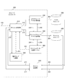
- FIG. 3 is a diagram illustrating a configuration example of a storage controller 200 according to the first embodiment of the present technology.
- FIG. It is a figure showing an example of composition of cache data management table 250 in an embodiment of this art.
- 3 is a flowchart illustrating an example of a processing procedure for an access request in a cache operation mode according to the first embodiment of the present technology.
- 3 is a flowchart illustrating an example of a processing procedure for an access request in a parallel operation mode according to the first embodiment of the present technology.
- FIG. 3 is a flowchart illustrating an example of a processing procedure for state control in an operation mode according to the first embodiment of the present technology. It is a figure showing an example of composition of storage controller 200 in a 2nd embodiment of this art. It is a figure showing an example of relation between an operation mode in a 2nd embodiment of this art, and a cache hit rate. It is a figure showing an example of transition of an operation mode in a 2nd embodiment of this art. 12 is a flowchart illustrating an example of a processing procedure for state control in an operation mode according to the second embodiment of the present technology. It is a flowchart which shows the example of a process sequence of the prior
- First embodiment example of suppressing cache access accompanying a miss hit when the hit rate increases
- Second Embodiment Example in which cache write-back processing is issued at any time when throughput decreases
- FIG. 1 is a diagram illustrating an example of an overall configuration of an information processing system according to an embodiment of the present technology.
- This information processing system includes a host computer 100, a storage controller 200, a master storage 300, and a cache storage 400.
- the storage controller 200, master storage 300, and cache storage 400 constitute a storage system.
- the host computer 100 issues a command for requesting data read processing or write processing to the storage system.
- the host computer 100 has a function of transmitting a command for instructing the operation of the storage controller 200 and an address indicating an operation target of the command to the storage controller 200 through the signal line 102.
- the host computer 100 has a function of transmitting and receiving data to and from the storage controller via a signal line (not shown).
- the storage controller 200 communicates with the host computer 100 to receive a command and requests the master storage 300 or the cache storage 400 to perform read processing or write processing.
- the storage controller 200 transmits a request for instructing the operation of the master storage 300 and an address indicating an operation target of the request to the master storage 300 via the signal line 203. Further, the storage controller 200 transmits a request for instructing the operation of the cache storage 400 and an address indicating an operation target of the request to the cache storage 400 through the signal line 204. Further, the storage controller 200 performs data transmission / reception with the master storage 300 or the cache storage 400 through a signal line (not shown).
- the master storage 300 is a storage that stores all data as a storage system.
- the master storage 300 is a storage device that has a larger capacity and a slower response speed than the cache storage 400.
- the master storage 300 reads or writes data according to a request received from the storage controller 200 via the signal line 203.
- the master storage 300 is an example of the first storage described in the claims.
- the cache storage 400 is storage that holds frequently accessed data.
- the cache storage 400 is a storage device having a smaller capacity and a faster response speed than the master storage 300, and operates as a cache of the master storage 300. That is, a part of the data of the master storage 300 is stored in the cache storage 400.
- the cache storage 400 reads or writes data according to a request received from the storage controller 200 via the signal line 204.
- the cache storage 400 is an example of a second storage described in the claims.
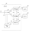
- FIG. 2 is a diagram illustrating a configuration example of the storage controller 200 according to the first embodiment of the present technology.
- the storage controller 200 includes a cache determination unit 210, a master storage access request unit 230, a cache storage access request unit 240, a cache data management table 250, and an operation mode management unit 260.
- the cache determination unit 210 determines whether or not data to be accessed is held in the cache storage 400 with respect to a command that requests read processing and write processing of data issued to the storage system.
- the cache determination unit 210 determines whether or not the data to be accessed is held in the cache storage 400 by referring to the cache data management table 250. This determination result is supplied to the operation mode management unit 260 via the signal line 216.
- the cache determination unit 210 determines which of the master storage 300 and the cache storage 400 should be accessed according to the operation mode managed by the operation mode management unit 260. Thereby, the cache determination unit 210 instructs the master storage access request unit 230 to access via the signal line 213 when accessing the master storage 300. On the other hand, when accessing the cache storage 400, the cache storage access request unit 240 is instructed to access via the signal line 214.
- the cache data management table 250 is a table for managing an area held in the cache storage 400. Since the cache storage 400 holds only frequently accessed data of the storage system data, it is necessary to manage which area is held and the access frequency. Therefore, an area held in the cache storage 400 is managed in the cache data management table 250. Information managed in the cache data management table 250 is supplied to the cache determination unit 210 and the cache storage access request unit 240 through signal lines 251 and 254. The specific contents of information managed in the cache data management table 250 will be described later.
- the operation mode management unit 260 manages the operation mode of the storage system.
- the operation mode defines how the master storage 300 and the cache storage 400 operate as a storage system.
- the first embodiment includes a parallel operation mode in which the master storage 300 and the cache storage 400 operate in parallel, and a cache operation mode in which the cache storage 400 performs an original operation of the cache.
- the operation mode managed by the operation mode management unit 260 is supplied to the cache determination unit 210 via the signal line 261.
- the master storage access request unit 230 makes an access request to the master storage 300 via the signal line 203 in accordance with an instruction from the cache determination unit 210.
- the cache storage access request unit 240 makes an access request to the cache storage 400 via the signal line 204 in accordance with an instruction from the cache determination unit 210.
- the cache storage 400 Since the cache storage 400 holds only frequently accessed data among the data in the storage system, the data moves between the master storage 300 and the cache storage 400 as time passes.
- a cache registration request is issued from the master storage 300 to the cache storage 400 via the signal line 234.
- a write back request is issued from the cache storage 400 to the master storage 300 via the signal line 243.
- the state of the cache storage 400 is appropriately supplied to the cache data management table 250 via the signal line 245.
- the cache determination unit 210, the master storage access request unit 230, and the cache storage access request unit 240 are an example of an access request unit described in the claims.
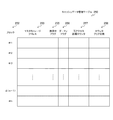
- FIG. 3 is a diagram illustrating a configuration example of the cache data management table 250 according to the embodiment of the present technology.
- the cache data management table 250 is managed for each block 252 and holds a master storage address 253, a busy flag 255, a dirty flag 256, a reaccess distance counter 257, and a counter clear count 258.
- the block 252 is a management unit of the cache storage 400.
- the cache storage 400 is divided into a plurality of areas, and each area is managed as a block. In this example, it is assumed that a maximum of n blocks can be secured in the cache storage 400.
- the master storage address 253 holds the address in the master storage 300 corresponding to the block of the cache storage 400. Thereby, the correspondence between the master storage 300 and the cache storage 400 is shown.
- the in-use flag 255 is a flag indicating whether or not the corresponding block of the cache storage 400 is in use. If the in-use flag 255 indicates “in use”, the block is valid. If the in-use flag 255 indicates “not in use”, the block is invalid.
- the dirty flag 256 is a flag indicating whether or not the corresponding block of the cache storage 400 matches the contents of the master storage 300 indicated by the master storage address 253. If the dirty flag 256 indicates “clean”, the contents of the corresponding block are in agreement, and if “dirty” is indicated, the contents of the corresponding block are not in agreement.
- the dirty flag 256 is set to “clean”. Thereafter, when data is written only to the cache storage 400, the dirty flag 256 is set to “dirty”.
- the dirty flag 256 indicates “dirty”, the data in the cache storage 400 is the latest. Therefore, in this case, it is necessary to read from the cache storage 400 at the time of reading, and it is necessary to write back data from the cache storage 400 to the master storage 300 when a block on the cache storage 400 is evicted.
- the re-access distance counter 257 is a counter that counts the total number of access requests from the previous access in the area. That is, the re-access distance counter 257 is incremented every time any area is accessed, and is cleared when the area is accessed. Therefore, the re-access distance counter 257 indicates an interval from the previous access.
- the counter clear count 258 is a counter that counts the number of times the re-access distance counter 257 is cleared. That is, the counter clear count 258 indicates the access frequency of the area.
- the cache determination unit 210 controls to replace the blocks held in the cache storage 400 so that the cache storage 400 holds only frequently accessed data among the data in the storage system. At this time, when determining which block is to be evicted from the cache storage 400, the reaccess distance counter 257 and the counter clear count 258 are referred to, and the eviction target is determined according to an LRU (Least Recently Used) algorithm or the like.
- LRU east Recently Used
- the cache determination unit 210 refers to the master storage address 253, confirms whether an address corresponding to the access request exists in the cache data management table 250, and performs cache hit determination.
- a cache hit occurs, that is, when data is stored in the cache storage 400, after the access request to the cache storage 400 is completed, the dirty flag 256 is set to “dirty” in the case of a write processing request.
- the re-access distance counter 257 is cleared and the counter clear count 258 is added.
- the operation mode is the cache operation mode
- the unused area is searched with reference to the in-use flag 255, and the use of the unused area is started.
- the usage frequency is calculated based on the reaccess distance counter 257 and the counter clear count 258, and the area with the lowest usage frequency is determined. Then, the cached data in the least frequently used area is written back to the master storage 300 and used as a cache area for a new request.
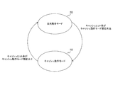
- FIG. 4 is a diagram illustrating a transition example of the operation mode according to the first embodiment of the present technology.
- two modes of a cache operation mode 10 and a parallel operation mode 20 are assumed as operation modes.
- the cache operation mode 10 is a mode in which the cache storage 400 performs an original operation of the cache.
- a new block is secured on the cache storage 400 when a cache miss occurs.
- the existing block is evicted to the master storage 300.
- the dirty flag 256 of the block indicates “dirty”
- the data of the block is written back to the master storage 300. Therefore, there is a possibility of affecting the throughput of the storage system for the data transfer.
- the parallel operation mode 20 is a mode in which the master storage 300 and the cache storage 400 operate in parallel.
- this parallel operation mode 20 since the master storage 300 is accessed when a cache miss occurs, the data in the cache storage 400 is not replaced. Therefore, although there is a possibility that the hit rate will decrease in the future, it is possible to suppress a decrease in throughput due to data replacement.
- the operation mode management unit 260 changes the operation mode from the cache operation mode 10 to the parallel operation mode 20.
- the operation mode management unit 260 changes the operation mode from the parallel operation mode 20 to the cache operation mode 10.
- the cache hit rate can be calculated as follows.
- the operation mode management unit 260 calculates the cache hit rate according to the information obtained from the cache determination unit 210 via the signal line 216. That is, the cache determination unit 210 determines whether or not the access is to the cache registered area in response to the read processing and write processing access requests issued to the storage system. Further, the cache determination unit 210 identifies the request type and the data transfer size, which are the configuration information of the access request. The operation mode management unit 260 calculates the cache hit rate using these pieces of information.
- the cache operation mode threshold value can be set as follows. Performance information exists in each storage device included in the storage system. The performance information includes the response speed for a specific size access request, the number of requests that can process a specific size access request per second (IOPS), and the throughput that indicates the data size that can be transferred per second that can be calculated from the IOPS. It is. A cache hit rate is calculated based on the performance information.
- the maximum throughput ST Storage system Throughput
- MT the maximum throughput (Master storage Throughput) of the master storage 300
- CT the maximum throughput (Cache storage Throughput) of the cache storage 400.
- ST MT + CT This is because each storage can operate independently when parallel operation is performed.
- ThCR 0.9CT / (0.9CT + MT)
- the calculation is based on the throughput, but it is also possible to calculate the target cache hit rate using the number of access requests (IOPS) that can be processed per second in the same manner as described above.
- IOPS access requests
- FIG. 5 is a flowchart illustrating an example of a processing procedure for an access request in the cache operation mode according to the first embodiment of the present technology.
- the cache determination unit 210 determines whether the data to be accessed is held in the cache storage 400 (step S911).
- the determination result and the metadata such as the data size and type of the access request are collected by the operation mode management unit 260 and used for calculation of the cache hit rate and control of the operation mode.
- a cache storage access request is generated from the cache area registration information managed in the cache data management table 250 and the access request configuration information (step S931). Then, the cache storage access request unit 240 accesses the cache storage 400 (step S932).
- a cache unused area is searched in the cache data management table 250 in order to allocate a cache area to the cache storage 400 in response to the access request (step S921).
- cache data eviction processing is performed in order to allocate an area of low usage frequency to the new area (step S923).
- the cache data eviction process data reading from the cache storage 400 and data writing to the master storage 300 are performed.
- the access process of the eviction process is completed, the information managed in the cache data management table 250 is reset and the use of the area is started. If an unused area exists (step S922: No), the unused area is used.
- step S924 If the access request is a read request (step S924: Yes), a read request for the master storage 300 is generated (step S925). Then, the master storage access request unit 230 performs read access to the master storage 300 (step S926).
- a write request for the cache storage 400 is generated (step S927). Then, the cache storage access request unit 240 performs write access to the cache storage 400 (step S928).
- the cache data management table 250 is updated as necessary (step S933). For example, as described above, the re-access distance counter 257 and the counter clear count 258 are updated. Thereafter, a response process to the access request is performed (step S934).
- FIG. 6 is a flowchart illustrating an example of a processing procedure for an access request in the parallel operation mode according to the first embodiment of the present technology.
- the cache determination unit 210 determines whether data to be accessed is held in the cache storage 400 (step S811).
- the determination result and the metadata such as the data size and type of the access request are collected by the operation mode management unit 260 and used for calculation of the cache hit rate and control of the operation mode.
- a cache storage access request is generated from the cache area registration information managed in the cache data management table 250 and the access request configuration information (step S831). Then, the cache storage access request unit 240 accesses the cache storage 400 (step S832).
- step S812 In the case of a cache miss hit (step S812: No), an access request for the master storage 300 is generated (step S821). Then, the master storage access request unit 230 performs read or write access to the master storage 300 (step S822).
- the cache data management table 250 is updated as necessary (step S833). For example, as described above, the re-access distance counter 257 and the counter clear count 258 are updated. Thereafter, response processing to the access request is performed (step S834).
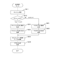
- FIG. 7 is a flowchart illustrating an example of a processing procedure for state control in the operation mode according to the first embodiment of the present technology.
- the operation mode management unit 260 calculates a cache hit rate based on the information from the cache determination unit 210 (step S711). As a result, when the cache hit rate changes so far and crosses the cache operation mode threshold value (step S712: Yes), the operation mode is changed as follows.
- step S713 cache operation mode threshold or higher
- the operation mode management unit 260 changes the operation mode to the parallel operation mode (step S722).
- step S713 less than the cache operation mode threshold
- the operation mode management unit 260 transitions the operation mode to the cache operation mode (step S721).
- the response speed of the master storage 300 is 20 ⁇ s (microseconds)
- the number of access requests (IOPS) that can be processed in 1 second (1 s) is 50,000
- the response speed of the cache storage 400 is 2 ⁇ s
- the IOPS is 500. , 000.
- the processing time for one access request when a mishit occurs is 22 ⁇ s for reading from the cache storage 400, writing to the master storage 300, and writing to the cache storage 400.
- it is necessary to further read from the master storage 300 which requires a processing time of 42 ⁇ s.
- the cache hit rate is 90.9% according to the following equation. 500,000 / 550,000 ⁇ 90.9%
- the performance as a storage system can be improved by using different operation modes according to the cache hit rate.
- Second Embodiment> In the first embodiment described above, when the cache hit rate becomes higher than a certain range, access requests to the master storage 300 do not occur so much, and the idle time during which no processing occurs for the master storage 300 increases. May end up. That is, the storage system is not in a sufficient performance state. Therefore, in the second embodiment, in a state where the throughput is lowered, a process of writing back cache data that is used less frequently is executed. As a result, the load of the write-back process in the cache operation mode is reduced, and the performance of the storage system is further improved.
- FIG. 8 is a diagram illustrating a configuration example of the storage controller 200 according to the second embodiment of the present technology.
- the storage controller 200 in the second embodiment differs from the first embodiment in that it further includes an access monitoring unit 270, and the other configurations are the same.
- the access monitoring unit 270 monitors each access request in the storage system and monitors performance for the access request.
- the access monitoring unit 270 receives the processing status in the master storage 300 via the signal line 302. Further, the access monitoring unit 270 receives the processing status in the cache storage 400 via the signal line 402.
- the access monitoring unit 270 also receives access request configuration information for the master storage 300 and the cache storage 400 via the signal line 217. As a result, the access monitoring unit 270 can acquire throughput information of processing in the master storage 300 and the cache storage 400.
- the access monitoring unit 270 supplies the throughput information acquired in this way to the cache determination unit 210 via the signal line 271.
- the cache determination unit 210 determines whether or not cache data write-back processing is possible based on the throughput information.
- FIG. 9 is a diagram illustrating a relationship example between the operation mode and the cache hit rate according to the second embodiment of the present technology.
- the target cache hit rate is calculated from the performance information of the master storage 300 and the cache storage 400 as in the first embodiment described above.
- a cache operation mode threshold and a cache organization mode threshold are determined from the target cache hit rate.
- the cache operation mode threshold is smaller than the target cache hit rate, and the cache organization mode threshold is larger than the target cache hit rate.
- the operation mode management unit 260 changes the operation mode from the parallel operation mode 20 to the cache organization mode 30.
- the operation mode management unit 260 changes the operation mode from the cache organization mode 30 to the parallel operation mode 20.
- the operation mode management unit 260 changes the operation mode from the parallel operation mode 20 to the cache operation mode 10.
- the processing procedure for the access request in the cache reduction mode is the same as that in the parallel operation mode in the first embodiment described above. That is, in the cache organization mode, as in the parallel operation mode, the cache hit rate is equal to or higher than the cache operation mode threshold value, so that the data in the cache storage 400 is not replaced even in the cache organization mode. Therefore, detailed description of the processing procedure for the access request in the cache reduction mode is also omitted.
- the operation mode management unit 260 calculates a cache hit rate based on the information from the cache determination unit 210 (step S711). As a result, when the cache hit rate changes so far and crosses the cache operation mode threshold value (step S712: Yes), the operation mode is changed as follows.
- step S713 When the cache hit rate is less than the cache operation mode threshold (step S713: less than the cache operation mode threshold), the operation mode management unit 260 transitions the operation mode to the cache operation mode (step S721).
- the operation mode management unit 260 changes the operation mode to the parallel operation mode (step S722). ).
- step S714 cache organization mode threshold or higher
- the operation mode management unit 260 changes the operation mode to the cache organization mode (step S723).
- FIG. 12 is a flowchart illustrating an example of a processing procedure of the preceding writing back processing according to the second embodiment of the present technology.
- the cache data that is used less frequently is written back in a state where the throughput is low.
- This preceding write-back process is executed in parallel with the process for other access requests.
- the following processing is performed with the operation mode transitioning to the cache organization mode or the cache operation mode as a trigger. Therefore, it is assumed that the preceding write-back processing is executed in the cache organizing mode or the cache operation mode, and is not executed in the parallel operation mode. However, this is merely an example, and the preceding writing back processing may be executed even in the parallel operation mode. Even in this case, the performance of the entire storage system can be ensured by proceeding with processing after confirming the throughput.
- whether or not the advance writing back process is possible is determined by paying attention to the throughput of the cache storage 400. That is, in this example, the throughput of the master storage 300 is not monitored. The reason is that, in the cache organization mode, since the cache hit rate is high, the ratio of accessing the cache storage 400 is high, and the access to the master storage 300 is considered to be small. Further, in the cache operation mode, it is considered that access to the cache storage 400 occurs for cache registration at the time of a cache miss, and access to the master storage 300 is reduced. As described above, in this example, attention is paid to the throughput of the cache storage 400, but the influence on the storage system may be further reduced by checking the throughput of the master storage 300 together.
- the access monitoring unit 270 acquires the throughput information and supplies it to the cache determination unit 210 (step S611). If the throughput of the cache storage 400 is greater than or equal to the write-back process threshold (step S612: greater than or equal to the write-back process threshold), the cache determination unit 210 does not execute the preceding write-back process.
- the cache determination unit 210 searches the write-back candidate block with reference to the cache data management table 250 (Ste S613). At this time, the reaccess distance counter 257 and the counter clear count 258 are referred to, and a block having a low use frequency is searched. For this search, a data structure (for example, a list structure) for holding a write-back candidate block in advance may be provided. If no write-back candidate block is found (step S614: No), the preceding write-back process is not executed.
- step S614 If a write-back candidate block is found (step S614: Yes), the data written in the write-back candidate block is read from the cache storage 400 and written back to the master storage 300 (step S615). At this time, the write-back process is performed on the block in which the dirty flag 256 is in the “dirty” state. After the write-back process is performed, the dirty flag 256 is in a “clean” state. As a result, when a miss-hit occurs, data writing back becomes unnecessary, and the block can be reused simply by resetting the in-use flag 255 to “unused”.
- the write-back process at the time of a miss hit is performed by executing the cache data write-back process with low usage frequency in a state where the throughput is low. And the performance of the entire system can be improved.
- the cache hit rate is 95% for 500,000 accesses
- the access to the cache storage 400 is 475,000 times and the access to the master storage 300 is 25,000 times.
- there is a margin in each band and by performing the eviction processing in the band where the margin is available, processing is performed without affecting the command from the host computer 100 and causing no performance degradation. Is possible.
- the processing procedure described in the above embodiment may be regarded as a method having a series of these procedures, and a program for causing a computer to execute these series of procedures or a recording medium storing the program. You may catch it.
- a recording medium for example, a CD (Compact Disc), an MD (MiniDisc), a DVD (Digital Versatile Disc), a memory card, a Blu-ray disc (Blu-ray (registered trademark) Disc), or the like can be used.
- this technique can also take the following structures.
- an access request unit that requests access to the first storage and the second storage that has a faster response speed than the first storage and stores a part of the data of the first storage; Whether or not data should be transferred from the first storage to the second storage when access to data not stored in the second storage occurs is managed based on the usage status of the second storage
- a storage controller comprising an operation management unit.
- the operation management unit determines a usage status of the second storage according to a hit rate indicating a ratio at which data to be accessed is stored in the second storage. .
- the operation management unit sets the cache operation mode when the hit rate is low based on a predetermined threshold, and sets the parallel operation mode when the hit rate is high,
- the access request unit requests data transfer from the first storage to the second storage in the cache operation mode when an access to data not stored in the second storage occurs, and
- the operation management unit sets the cache operation mode when the hit rate is low based on the first threshold, and sets the cache operation mode when the hit rate is high based on the second threshold higher than the first threshold.
- the access request unit requests data transfer from the first storage to the second storage in the cache operation mode when an access to data not stored in the second storage occurs, and The storage controller according to (4), wherein data transfer from the first storage to the second storage is not requested in the parallel operation mode or the cache reduction mode.
- the access request unit requests the write-back candidate data to be written back from the second storage to the first storage in the cache organization mode or the cache operation mode, and in the parallel operation mode.
- the storage controller according to (5), wherein the write-back candidate data is not requested to be written back.
- the first storage A second storage having a faster response speed than the first storage and storing a part of the data of the first storage;
- An access request unit that requests access to the first and second storages; Whether or not data should be transferred from the first storage to the second storage when access to data not stored in the second storage occurs is managed based on the usage status of the second storage
- a storage system comprising an operation management unit.
- (8) a procedure in which the access request unit requests access to the first storage and the second storage having a faster response speed than the first storage and storing a part of the data of the first storage; , Whether the operation management unit should transfer data from the first storage to the second storage when access to data that is not stored in the second storage occurs occurs.
- a storage controller control method comprising: (9) a procedure for requesting access to the first storage and the second storage having a faster response speed than the first storage and storing a part of the data of the first storage; Whether or not data should be transferred from the first storage to the second storage when access to data not stored in the second storage occurs is managed based on the usage status of the second storage A program that causes a computer to execute procedures.
Landscapes
- Engineering & Computer Science (AREA)
- Theoretical Computer Science (AREA)
- General Engineering & Computer Science (AREA)
- Physics & Mathematics (AREA)
- General Physics & Mathematics (AREA)
- Computer Hardware Design (AREA)
- Quality & Reliability (AREA)
- Human Computer Interaction (AREA)
- Memory System Of A Hierarchy Structure (AREA)
Abstract
キャッシュデータの追出し処理を抑制して、システム全体としてのスループットを向上させる。 ストレージコントローラは、アクセス要求部と動作管理部とを備える。アクセス要求部は、第1のストレージおよび第1のストレージより応答速度が速く第1のストレージのデータの一部が格納される第2のストレージに対して、アクセスを要求する。動作管理部は、第2のストレージに格納されないデータへのアクセスが発生した際に、第1のストレージから第2のストレージにデータを転送すべきか否かを、第2のストレージの利用状況に基づいて管理する。
Description
本技術は、ストレージシステムに関する。詳しくは、応答速度が異なる複数のストレージを利用したストレージシステム、ストレージコントローラ、および、これらにおける処理方法ならびに当該方法をコンピュータに実行させるプログラムに関する。
コンピュータシステムの記憶装置として使われるストレージデバイスは、応答速度が遅いため、応答速度が速い揮発性または不揮発性の記憶装置をキャッシュとして利用して、ストレージデバイスの動作上の性能を向上させる方法が提案されている。このようなキャッシュを持つストレージデバイスでは、主に揮発性のメモリがキャッシュとして使われ、NANDメモリを利用したフラッシュストレージや磁気ディスクを利用したHDDが主となる記憶装置として使われている。このようなストレージデバイスでは、キャッシュと記憶装置との応答速度の差が大きく、キャッシュに対するアクセス比率(キャッシュヒット率)を上げることがストレージデバイスの性能向上につながる。そのため、このキャッシュヒット率を上げる手法が提案されている。例えば、ホストが小さいフットプリントを持つ場合には全てのデータをキャッシュに格納し、大きいフットプリントを持つ場合には最初の部分をキャッシュに格納して残りをディスクに格納するシステムが提案されている(例えば、特許文献1参照。)。
読出し要求または書込み要求のアクセス領域のランダム性が強い場合や、頻繁にアクセスする領域が短期間で変わるような場合、キャッシュヒット率を高く保つためには、キャッシュデータの追出し処理が必要となる。この追出し処理による帯域占有により、ストレージシステムとしての性能が低下してしまうという問題がある。
本技術はこのような状況に鑑みて生み出されたものであり、キャッシュデータの追出し処理を抑制して、システム全体としてのスループットを向上させることを目的とする。
本技術は、上述の問題点を解消するためになされたものであり、その第1の側面は、第1のストレージおよび上記第1のストレージより応答速度が速く上記第1のストレージのデータの一部が格納される第2のストレージに対してアクセスを要求するアクセス要求部と、上記第2のストレージに格納されないデータへのアクセスが発生した際に上記第1のストレージから上記第2のストレージにデータを転送すべきか否かを上記第2のストレージの利用状況に基づいて管理する動作管理部とを具備するストレージコントローラ、そのストレージコントローラを備えるストレージシステム、そのストレージコントローラの制御方法、および、そのプログラムである。これにより、第2のストレージの利用状況に基づいて第1のストレージから上記第2のストレージにデータを転送すべきか否かを管理するという作用をもたらす。
また、この第1の側面において、上記動作管理部は、アクセス対象のデータが上記第2のストレージに格納されていた比率を示すヒット率に従って上記第2のストレージの利用状況を判断するようにしてもよい。これにより、ヒット率に基づいて第1のストレージから上記第2のストレージにデータを転送すべきか否かを管理するという作用をもたらす。
また、この第1の側面において、上記動作管理部は、上記ヒット率が所定の閾値を基準として低い場合にはキャッシュ動作モードに設定し、高い場合には並列動作モードに設定して、上記アクセス要求部は、上記第2のストレージに格納されないデータへのアクセスが発生した際に、上記キャッシュ動作モードにおいては上記第1のストレージから上記第2のストレージへのデータ転送を要求し、上記並列動作モードにおいては上記第1のストレージから上記第2のストレージへのデータ転送を要求しないようにしてもよい。これにより、ヒット率を基準とした動作モードに応じて、第1のストレージから上記第2のストレージにデータを転送すべきか否かを管理するという作用をもたらす。
また、この第1の側面において、上記第2のストレージにおけるアクセスを監視して上記第2のストレージのスループットを取得するアクセス監視部をさらに具備し、上記アクセス要求部は、上記第2のストレージに格納されるデータのうちアクセス頻度の低いデータを書戻し候補データとして選択し、上記第2のストレージのスループットが所定の値よりも低くなった際に上記書戻し候補データを上記第2のストレージから上記第1のストレージに書き戻すよう要求するようにしてもよい。これにより、スループットが低くなった際に、第2のストレージから第1のストレージに書戻しを行うという作用をもたらす。
また、この第1の側面において、上記動作管理部は、上記ヒット率が第1の閾値を基準として低い場合にはキャッシュ動作モードに設定し、上記第1の閾値よりも高い第2の閾値を基準として高い場合にはキャッシュ整理モードに設定し、上記第1の閾値と上記第2の閾値の間である場合には並列動作モードに設定して、上記アクセス要求部は、上記第2のストレージに格納されないデータへのアクセスが発生した際に、上記キャッシュ動作モードにおいては上記第1のストレージから上記第2のストレージへのデータ転送を要求し、上記並列動作モードまたは上記キャッシュ整理モードにおいては上記第1のストレージから上記第2のストレージへのデータ転送を要求しないようにしてもよい。これにより、ヒット率を基準とした動作モードに応じて、第1のストレージから上記第2のストレージにデータを転送すべきか否かを管理するという作用をもたらす。
また、この第1の側面において、上記アクセス要求部は、上記キャッシュ整理モードまたは上記キャッシュ動作モードにおいては上記書戻し候補データを上記第2のストレージから上記第1のストレージに書き戻すよう要求し、上記並列動作モードにおいては上記書戻し候補データの書戻しを要求しないようにしてもよい。これにより、ヒット率を基準とした動作モードに応じて、第2のストレージから第1のストレージに書戻しを行うという作用をもたらす。
本技術によれば、キャッシュデータの追出し処理を抑制して、システム全体としてのスループットを向上させることができるという優れた効果を奏し得る。なお、ここに記載された効果は必ずしも限定されるものではなく、本開示中に記載されたいずれかの効果であってもよい。
以下、本技術を実施するための形態(以下、実施の形態と称する)について説明する。説明は以下の順序により行う。
1.第1の実施の形態(ヒット率上昇時に、ミスヒットに伴うキャッシュアクセスを抑制する例)
2.第2の実施の形態(スループット低下時に、キャッシュ書戻し処理を随時発行する例)
1.第1の実施の形態(ヒット率上昇時に、ミスヒットに伴うキャッシュアクセスを抑制する例)
2.第2の実施の形態(スループット低下時に、キャッシュ書戻し処理を随時発行する例)
<1.第1の実施の形態>
[情報処理システムの構成]
図1は、本技術の実施の形態における情報処理システムの全体構成の一例を示す図である。この情報処理システムは、ホストコンピュータ100と、ストレージコントローラ200と、マスタストレージ300と、キャッシュストレージ400とから構成される。ストレージコントローラ200、マスタストレージ300およびキャッシュストレージ400は、ストレージシステムを構成する。
[情報処理システムの構成]
図1は、本技術の実施の形態における情報処理システムの全体構成の一例を示す図である。この情報処理システムは、ホストコンピュータ100と、ストレージコントローラ200と、マスタストレージ300と、キャッシュストレージ400とから構成される。ストレージコントローラ200、マスタストレージ300およびキャッシュストレージ400は、ストレージシステムを構成する。
ホストコンピュータ100は、ストレージシステムに対してデータのリード処理やライト処理等を要求するコマンドを発行するものである。このホストコンピュータ100は、信号線102により、ストレージコントローラ200の動作を指示するコマンドとそのコマンドの操作対象を示すアドレスとをストレージコントローラ200に送信する機能を有する。また、このホストコンピュータ100は、図示しない信号線により、ストレージコントローラと間のデータ送受信を行う機能を有する。
ストレージコントローラ200は、ホストコンピュータ100と通信してコマンドを受信し、マスタストレージ300またはキャッシュストレージ400に対してリード処理またはライト処理を要求するものである。このストレージコントローラ200は、信号線203により、マスタストレージ300の動作を指示するリクエストとそのリクエストの操作対象を示すアドレスとをマスタストレージ300に送信する。また、このストレージコントローラ200は、信号線204により、キャッシュストレージ400の動作を指示するリクエストとそのリクエストの操作対象を示すアドレスとをキャッシュストレージ400に送信する。また、このストレージコントローラ200は、図示しない信号線により、マスタストレージ300またはキャッシュストレージ400とのデータ送受信を行う。
マスタストレージ300は、ストレージシステムとしての全てのデータを記憶するストレージである。このマスタストレージ300は、キャッシュストレージ400より大容量かつ応答速度が遅い記憶装置である。このマスタストレージ300は、ストレージコントローラ200から信号線203を介して受けたリクエストに従ってデータの読出しまたは書込みを行う。なお、マスタストレージ300は、特許請求の範囲に記載の第1のストレージの一例である。
キャッシュストレージ400は、アクセス頻度の高いデータを保持するストレージである。このキャッシュストレージ400は、マスタストレージ300より小容量かつ応答速度が速い記憶装置であり、マスタストレージ300のキャッシュとして動作する。すなわち、このキャッシュストレージ400には、マスタストレージ300のデータの一部が格納される。このキャッシュストレージ400は、ストレージコントローラ200から信号線204を介して受けたリクエストに従ってデータの読出しまたは書込みを行う。なお、キャッシュストレージ400は、特許請求の範囲に記載の第2のストレージの一例である。
[ストレージコントローラの構成]
図2は、本技術の第1の実施の形態におけるストレージコントローラ200の構成例を示す図である。このストレージコントローラ200は、キャッシュ判定部210と、マスタストレージアクセス要求部230と、キャッシュストレージアクセス要求部240と、キャッシュデータ管理テーブル250と、動作モード管理部260とを備える。
図2は、本技術の第1の実施の形態におけるストレージコントローラ200の構成例を示す図である。このストレージコントローラ200は、キャッシュ判定部210と、マスタストレージアクセス要求部230と、キャッシュストレージアクセス要求部240と、キャッシュデータ管理テーブル250と、動作モード管理部260とを備える。
キャッシュ判定部210は、ストレージシステムに対して発行されたデータのリード処理およびライト処理を要求するコマンドについて、アクセス対象となるデータがキャッシュストレージ400に保持されているか否かを判定するものである。このキャッシュ判定部210は、キャッシュデータ管理テーブル250を参照することにより、アクセス対象となるデータがキャッシュストレージ400に保持されているか否かを判定する。この判定結果は、信号線216を介して動作モード管理部260に供給される。
また、このキャッシュ判定部210は、動作モード管理部260によって管理される動作モードに応じて、マスタストレージ300またはキャッシュストレージ400の何れにアクセスすべきかを判定する。これにより、このキャッシュ判定部210は、マスタストレージ300にアクセスする場合には信号線213を介してマスタストレージアクセス要求部230にアクセスを指示する。一方、キャッシュストレージ400にアクセスする場合には信号線214を介してキャッシュストレージアクセス要求部240にアクセスを指示する。
キャッシュデータ管理テーブル250は、キャッシュストレージ400に保持されている領域を管理するテーブルである。キャッシュストレージ400はストレージシステムのデータのうちアクセス頻度の高いデータのみを保持するため、何れの領域が保持されているか、および、そのアクセス頻度を管理する必要がある。そのため、このキャッシュデータ管理テーブル250においてキャッシュストレージ400に保持されている領域が管理される。このキャッシュデータ管理テーブル250において管理される情報は、信号線251および254によって、キャッシュ判定部210およびキャッシュストレージアクセス要求部240に供給される。なお、このキャッシュデータ管理テーブル250において管理される情報の具体的内容については後述する。
動作モード管理部260は、ストレージシステムの動作モードを管理するものである。動作モードは、ストレージシステムとしてマスタストレージ300およびキャッシュストレージ400がそれぞれどのように動作するかを定めるものである。第1の実施の形態においては、後述するように、マスタストレージ300およびキャッシュストレージ400が並列に動作を行う並列動作モードと、キャッシュストレージ400がキャッシュ本来の動作を行うキャッシュ動作モードとを備える。この動作モード管理部260によって管理される動作モードは、信号線261を介してキャッシュ判定部210に供給される。
マスタストレージアクセス要求部230は、キャッシュ判定部210からの指示に従って、信号線203を介してマスタストレージ300にアクセス要求を行うものである。キャッシュストレージアクセス要求部240は、キャッシュ判定部210からの指示に従って、信号線204を介してキャッシュストレージ400にアクセス要求を行うものである。
キャッシュストレージ400はストレージシステムのデータのうちアクセス頻度の高いデータのみを保持するため、時間の経過に伴いマスタストレージ300とキャッシュストレージ400との間でデータの移動が生じる。キャッシュストレージ400に領域が確保される際には、信号線234を介してマスタストレージ300からキャッシュストレージ400にキャッシュ登録要求が発行される。その後、キャッシュストレージ400の内容をマスタストレージ300に書き戻す際には、信号線243を介してキャッシュストレージ400からマスタストレージ300に書戻し要求が発行される。また、キャッシュストレージ400の状態は、信号線245を介して、適宜、キャッシュデータ管理テーブル250に供給される。
なお、キャッシュ判定部210、マスタストレージアクセス要求部230およびキャッシュストレージアクセス要求部240は、特許請求の範囲に記載のアクセス要求部の一例である。
図3は、本技術の実施の形態におけるキャッシュデータ管理テーブル250の構成例を示す図である。このキャッシュデータ管理テーブル250は、ブロック252毎に管理されており、マスタストレージアドレス253と、使用中フラグ255と、ダーティフラグ256と、再アクセス距離カウンタ257と、カウンタクリア回数258とを保持する。ブロック252は、キャッシュストレージ400の管理単位であり、キャッシュストレージ400を複数の領域に分割して、その各領域をブロックとして管理する。この例では、最大n個のブロックがキャッシュストレージ400に確保可能であることを想定している。
マスタストレージアドレス253は、キャッシュストレージ400のブロックに対応するマスタストレージ300内のアドレスを保持するものである。これにより、マスタストレージ300とキャッシュストレージ400との対応関係が示される。
使用中フラグ255は、キャッシュストレージ400の対応ブロックが使用中であるか否かを示すフラグである。使用中フラグ255が「使用中」を示していればそのブロックは有効であり、「未使用」を示していればそのブロックは無効である。
ダーティフラグ256は、キャッシュストレージ400の対応ブロックが、マスタストレージアドレス253によって示されるマスタストレージ300の内容と一致しているか否かを示すフラグである。ダーティフラグ256が「クリーン」を示していれば対応ブロックの内容は一致している状態であり、「ダーティ」を示していれば対応ブロックの内容は一致していない状態である。あるブロックがマスタストレージ300からキャッシュストレージ400に最初に登録されたときには、ダーティフラグ256は「クリーン」に設定される。その後、キャッシュストレージ400にのみデータを書き込んだ際に、ダーティフラグ256は「ダーティ」に設定される。ダーティフラグ256が「ダーティ」を示す場合には、キャッシュストレージ400のデータが最新であることになる。したがって、この場合、読出しの際にはキャッシュストレージ400から読み出す必要があり、また、キャッシュストレージ400上のブロックを追い出す際にはキャッシュストレージ400からマスタストレージ300にデータの書戻しが必要になる。
再アクセス距離カウンタ257は、その領域の前回のアクセスからの、全体のアクセス要求数を計数するカウンタである。すなわち、この再アクセス距離カウンタ257は、何れかの領域がアクセスされるたびに加算され、その領域にアクセスが発生するとクリアされる。したがって、この再アクセス距離カウンタ257は、前回のアクセスからの間隔を示す。
カウンタクリア回数258は、再アクセス距離カウンタ257がクリアされた回数を計数するカウンタである。すなわち、このカウンタクリア回数258は、その領域のアクセス頻度を示す。
キャッシュストレージ400とマスタストレージ300のブロックの割当ては、ダイレクトマッピング、セットアソシエイティブ、フルアソシエイティブなどの方法がある。例えば、2wayのセットアソシエイティブ方式の場合は、ブロック#1とブロック#2をセットにして領域の割当て管理が行われる。
キャッシュストレージ400はストレージシステムのデータのうちアクセス頻度の高いデータのみを保持するように、キャッシュ判定部210はキャッシュストレージ400に保持されるブロックを入れ替える制御を行う。その際、キャッシュストレージ400から何れのブロックを追い出すかを判断する際に、再アクセス距離カウンタ257およびカウンタクリア回数258が参照され、LRU(Least Recently Used)アルゴリズム等に従って、追出し対象が決定される。
キャッシュ判定部210は、マスタストレージアドレス253を参照して、アクセス要求に該当するアドレスがキャッシュデータ管理テーブル250に存在するか否かを確認し、キャッシュヒット判定を行う。キャッシュヒットした場合、すなわち、キャッシュストレージ400にデータが格納されていた場合、キャッシュストレージ400へのアクセス要求が完了した後、ライト処理要求の場合はダーティフラグ256を「ダーティ」に設定する。また、リード処理およびライト処理の何れの場合にも、再アクセス距離カウンタ257のクリアと、カウンタクリア回数258の加算を行う。
一方、キャッシュミスヒットの場合、動作モードがキャッシュ動作モードであれば、使用中フラグ255を参照して未使用領域を探索し、未使用領域の利用を開始する。未使用領域が存在しない場合は、再アクセス距離カウンタ257およびカウンタクリア回数258に基づいて利用頻度を算出し、利用頻度が一番低い領域を判定する。そして、その利用頻度が一番低い領域のキャッシュ済みデータをマスタストレージ300に書き戻し、新たな要求に対するキャッシュ領域として利用する。
[動作モード]
図4は、本技術の第1の実施の形態における動作モードの遷移例を示す図である。この第1の実施の形態では、動作モードとして、キャッシュ動作モード10および並列動作モード20の2つのモードを想定する。
図4は、本技術の第1の実施の形態における動作モードの遷移例を示す図である。この第1の実施の形態では、動作モードとして、キャッシュ動作モード10および並列動作モード20の2つのモードを想定する。
キャッシュ動作モード10は、キャッシュストレージ400がキャッシュ本来の動作を行うモードである。このキャッシュ動作モード10では、キャッシュミスヒット時にはキャッシュストレージ400上にブロックが新たに確保される。その際、キャッシュストレージ400上に未使用ブロックがない場合には、既存のブロックがマスタストレージ300に追い出される。このとき、そのブロックのダーティフラグ256が「ダーティ」を示していれば、そのブロックのデータはマスタストレージ300に書き戻される。そのため、そのデータ転送のためにストレージシステムとしてのスループットに影響を与える可能性がある。
並列動作モード20は、マスタストレージ300およびキャッシュストレージ400が並列に動作を行うモードである。この並列動作モード20では、キャッシュミスヒット時にはマスタストレージ300にアクセスが行われるため、キャッシュストレージ400のデータの入替えは生じない。したがって、将来的にヒット率が低下するおそれはあるが、データ入替えに伴うスループットの低下を抑制することができる。
キャッシュ動作モード10において動作が行われている間にキャッシュヒット率がキャッシュ動作モード閾値以上になると、動作モード管理部260は動作モードをキャッシュ動作モード10から並列動作モード20に遷移させる。一方、並列動作モード20において動作が行われている間にキャッシュヒット率がキャッシュ動作モード閾値未満になると、動作モード管理部260は動作モードを並列動作モード20からキャッシュ動作モード10に遷移させる。
[キャッシュヒット率]
キャッシュヒット率は、以下のように計算することができる。動作モード管理部260は、キャッシュ判定部210から信号線216を介して得られる情報に従って、キャッシュヒット率を計算する。すなわち、ストレージシステムに対して発行されたリード処理およびライト処理のアクセス要求に対して、キャッシュ判定部210においてキャッシュ登録済み領域へのアクセスか否かが判定される。また、キャッシュ判定部210において、アクセス要求の構成情報である要求の種類やデータ転送サイズが判明する。動作モード管理部260は、これらの情報を用いてキャッシュヒット率を計算する。
キャッシュヒット率は、以下のように計算することができる。動作モード管理部260は、キャッシュ判定部210から信号線216を介して得られる情報に従って、キャッシュヒット率を計算する。すなわち、ストレージシステムに対して発行されたリード処理およびライト処理のアクセス要求に対して、キャッシュ判定部210においてキャッシュ登録済み領域へのアクセスか否かが判定される。また、キャッシュ判定部210において、アクセス要求の構成情報である要求の種類やデータ転送サイズが判明する。動作モード管理部260は、これらの情報を用いてキャッシュヒット率を計算する。
[キャッシュ動作モード閾値]
キャッシュ動作モード閾値は、以下のように設定することができる。ストレージシステムが有する各ストレージデバイスには、性能情報が存在する。性能情報には、特定サイズのアクセス要求に対する応答速度、特定サイズのアクセス要求を1秒間に処理できる要求数(IOPS)、IOPSから算出可能な1秒間に転送可能なデータサイズを示すスループットなどが含まれる。これら性能情報に基づいてキャッシュヒット率が算出される。
キャッシュ動作モード閾値は、以下のように設定することができる。ストレージシステムが有する各ストレージデバイスには、性能情報が存在する。性能情報には、特定サイズのアクセス要求に対する応答速度、特定サイズのアクセス要求を1秒間に処理できる要求数(IOPS)、IOPSから算出可能な1秒間に転送可能なデータサイズを示すスループットなどが含まれる。これら性能情報に基づいてキャッシュヒット率が算出される。
例えば、ストレージシステムの最大スループットST(Storage system Throughput)は次式により計算される。ただし、MTはマスタストレージ300の最大スループット(Master storage Throughput)、CTはキャッシュストレージ400の最大スループット(Cache storage Throughput) である。
ST=MT+CT
これは、並列動作をさせた場合に、各ストレージが独立して動作可能なためである。
ST=MT+CT
これは、並列動作をさせた場合に、各ストレージが独立して動作可能なためである。
このときのキャッシュストレージ400へのアクセス要求の割合は次式によって求められ、これが目標のキャッシュヒット率TCR(Target Cache Ratio)となる。
TCR=CT/ST
TCR=CT/ST
キャッシュストレージ400のスループットが最大スループットの90%を超えた場合に、並列動作に遷移すると想定した場合、この時点の最大スループットからキャッシュ動作モード閾値ThCR(Threshold Cache Ratio)を次式により求める。
ThCR=0.9CT/(0.9CT+MT)
ThCR=0.9CT/(0.9CT+MT)
ここではスループットを基準として計算したが、1秒間に処理が可能なアクセス要求数(IOPS)を用いて、上述と同様に目標のキャッシュヒット率を計算することも可能である。各スループットを、各IOPSに置き換えることにより、同様の式でキャッシュ動作モード閾値を求めることが可能である。
[動作]
図5は、本技術の第1の実施の形態のキャッシュ動作モードにおけるアクセス要求に対する処理手順例を示す流れ図である。
図5は、本技術の第1の実施の形態のキャッシュ動作モードにおけるアクセス要求に対する処理手順例を示す流れ図である。
ホストコンピュータ100からストレージシステムに対してコマンドが発行されると、キャッシュ判定部210は、アクセス対象となるデータがキャッシュストレージ400に保持されているか否かを判定する(ステップS911)。この判定結果およびアクセス要求のデータサイズや種類などのメタデータは、動作モード管理部260によって収集され、キャッシュヒット率の計算や動作モードの制御に用いられる。
キャッシュヒットの場合(ステップS912:Yes)、キャッシュデータ管理テーブル250において管理されるキャッシュ領域の登録情報とアクセス要求の構成情報からキャッシュストレージアクセス要求が生成される(ステップS931)。そして、キャッシュストレージアクセス要求部240は、キャッシュストレージ400に対してアクセスを行う(ステップS932)。
キャッシュミスヒットの場合(ステップS912:No)、アクセス要求に対してキャッシュストレージ400にキャッシュ領域を割り当てるため、キャッシュデータ管理テーブル250においてキャッシュ未使用領域の探索を行う(ステップS921)。このとき、未使用領域が存在しない場合(ステップS922:Yes)、使用領域の中で利用頻度が低い領域を新しい領域に割り当てるために、キャッシュデータの追出し処理を行う(ステップS923)。キャッシュデータの追出し処理には、キャッシュストレージ400からのデータの読出しとマスタストレージ300へのデータの書込みが行われる。追出し処理のアクセス処理が完了すると、キャッシュデータ管理テーブル250において管理されている情報をリセットし、その領域の使用を開始する。なお、未使用領域が存在する場合には(ステップS922:No)、その未使用領域が使用される。
アクセス要求が読出し要求である場合(ステップS924:Yes)、マスタストレージ300に対する読出し要求が生成される(ステップS925)。そして、マスタストレージアクセス要求部230は、マスタストレージ300に対して読出しのアクセスを行う(ステップS926)。
アクセス要求が読出し要求または書込み要求の何れの場合であっても、キャッシュストレージ400に対する書込み要求が生成される(ステップS927)。そして、キャッシュストレージアクセス要求部240は、キャッシュストレージ400に対して書込みのアクセスを行う(ステップS928)。
キャッシュヒットまたはミスヒットの何れの場合であっても、キャッシュデータ管理テーブル250が必要に応じて更新される(ステップS933)。例えば、上述のように、再アクセス距離カウンタ257およびカウンタクリア回数258が更新される。その後、アクセス要求に対する応答処理が行われる(ステップS934)。
図6は、本技術の第1の実施の形態の並列動作モードにおけるアクセス要求に対する処理手順例を示す流れ図である。
ホストコンピュータ100からストレージシステムに対してコマンドが発行されると、キャッシュ判定部210は、アクセス対象となるデータがキャッシュストレージ400に保持されているか否かを判定する(ステップS811)。この判定結果およびアクセス要求のデータサイズや種類などのメタデータは、動作モード管理部260によって収集され、キャッシュヒット率の計算や動作モードの制御に用いられる。
キャッシュヒットの場合(ステップS812:Yes)、キャッシュデータ管理テーブル250において管理されるキャッシュ領域の登録情報とアクセス要求の構成情報からキャッシュストレージアクセス要求が生成される(ステップS831)。そして、キャッシュストレージアクセス要求部240は、キャッシュストレージ400に対してアクセスを行う(ステップS832)。
キャッシュミスヒットの場合(ステップS812:No)、マスタストレージ300に対するアクセス要求が生成される(ステップS821)。そして、マスタストレージアクセス要求部230は、マスタストレージ300に対して読出しまたは書込みのアクセスを行う(ステップS822)。
キャッシュヒットまたはミスヒットの何れの場合であっても、キャッシュデータ管理テーブル250が必要に応じて更新される(ステップS833)。例えば、上述のように、再アクセス距離カウンタ257およびカウンタクリア回数258が更新される。その後、アクセス要求に対する応答処理が行われる(ステップS834)。
図7は、本技術の第1の実施の形態における動作モードの状態制御の処理手順例を示す流れ図である。
動作モード管理部260は、キャッシュ判定部210からの情報に基づいてキャッシュヒット率を計算する(ステップS711)。その結果、それまでのキャッシュヒット率から変化し、キャッシュ動作モード閾値を跨いだ場合(ステップS712:Yes)、以下のように動作モードを遷移させる。
キャッシュヒット率がキャッシュ動作モード閾値以上になった場合(ステップS713:キャッシュ動作モード閾値以上)、動作モード管理部260は動作モードを並列動作モードに遷移させる(ステップS722)。一方、キャッシュヒット率がキャッシュ動作モード閾値未満になった場合(ステップS713:キャッシュ動作モード閾値未満)、動作モード管理部260は動作モードをキャッシュ動作モードに遷移させる(ステップS721)。
このように、本技術の第1の実施の形態によれば、マスタストレージ300とキャッシュストレージ400を並列に動作させるモードを追加することにより、キャッシュデータの入れ替えに伴う性能低下を回避することができる。
例えば、マスタストレージ300の応答速度が20μs(マイクロ秒)で、1秒(1s)間に処理可能なアクセス要求数(IOPS)が50,000、キャッシュストレージ400の応答速度が2μsで、IOPSが500,000であると想定する。ミスヒットが発生した場合の1回のアクセス要求に対する処理時間は、書込み要求の場合、キャッシュストレージ400からの読出し、マスタストレージ300への書込み、キャッシュストレージ400への書込みを実行するため22μsとなる。読出し要求の場合は、さらにマスタストレージ300からの読出しを実行する必要があり、42μsの処理時間を要してしまう。
キャッシュヒット率が90%の場合、10%のアクセス要求に対しては上述の処理を行う必要があるため、最大のIOPSは次式により求められる。
1s/(0.9×2μs+0.1×22μs)=250,000
1s/(0.9×2μs+0.1×22μs)=250,000
一方、マスタストレージ300とキャッシュストレージ400とをそれぞれ並列動作させる場合は、それぞれのアクセス要求は影響を受けることなく処理が可能であるため、最大のIOPSは次式により求められる。
500,000+50,000=550,000
また、この場合のキャッシュヒット率は次式により90.9%となる。
500,000/550,000≒90.9%
500,000+50,000=550,000
また、この場合のキャッシュヒット率は次式により90.9%となる。
500,000/550,000≒90.9%
このように、キャッシュヒット率がある程度高い状態においては、ほぼ同じキャッシュヒット率であっても、並列動作モードにおいてストレージシステムの性能を倍にすることが可能であることがわかる。したがって、本技術の第1の実施の形態のように、キャッシュヒット率に応じて動作モードを使い分けることにより、ストレージシステムとしての性能を向上させることができる。
<2.第2の実施の形態>
上述の第1の実施の形態では、キャッシュヒット率がある範囲を超えて高くなると、マスタストレージ300へのアクセス要求はあまり発生しなくなり、マスタストレージ300に対して処理が発生しないアイドル時間が増えてしまうことがある。すなわち、ストレージシステムとしては性能を十分に出せていない状態になる。そこで、この第2の実施の形態では、スループットが低下している状態において、利用頻度が低いキャッシュデータを書き戻す処理を実行する。これにより、キャッシュ動作モード時の書戻し処理の負荷を減らして、ストレージシステムとしてのさらなる性能向上を図る。
上述の第1の実施の形態では、キャッシュヒット率がある範囲を超えて高くなると、マスタストレージ300へのアクセス要求はあまり発生しなくなり、マスタストレージ300に対して処理が発生しないアイドル時間が増えてしまうことがある。すなわち、ストレージシステムとしては性能を十分に出せていない状態になる。そこで、この第2の実施の形態では、スループットが低下している状態において、利用頻度が低いキャッシュデータを書き戻す処理を実行する。これにより、キャッシュ動作モード時の書戻し処理の負荷を減らして、ストレージシステムとしてのさらなる性能向上を図る。
この第2の実施の形態における情報処理システムの全体構成は上述の第1の実施の形態と同様であるため、詳細な説明は省略する。
[ストレージコントローラの構成]
図8は、本技術の第2の実施の形態におけるストレージコントローラ200の構成例を示す図である。この第2の実施の形態におけるストレージコントローラ200は、第1の実施の形態と比べて、アクセス監視部270をさらに備える点において異なり、他の構成については同様である。
図8は、本技術の第2の実施の形態におけるストレージコントローラ200の構成例を示す図である。この第2の実施の形態におけるストレージコントローラ200は、第1の実施の形態と比べて、アクセス監視部270をさらに備える点において異なり、他の構成については同様である。
アクセス監視部270は、ストレージシステム内の各アクセス要求を監視し、アクセス要求に対する性能を監視するものである。このアクセス監視部270は、マスタストレージ300における処理状況を、信号線302を介して受け取る。また、このアクセス監視部270は、キャッシュストレージ400における処理状況を、信号線402を介して受け取る。また、このアクセス監視部270は、マスタストレージ300およびキャッシュストレージ400に対するアクセス要求の構成情報を、信号線217を介して受け取る。これにより、アクセス監視部270は、マスタストレージ300およびキャッシュストレージ400における処理のスループット情報を取得することができる。
アクセス監視部270は、このようにして取得したスループット情報を、信号線271を介してキャッシュ判定部210に供給する。キャッシュ判定部210は、このスループット情報に基づいてキャッシュデータの書戻し処理の可否を判断する。
[動作モード]
図9は、本技術の第2の実施の形態における動作モードとキャッシュヒット率との関係例を示す図である。
図9は、本技術の第2の実施の形態における動作モードとキャッシュヒット率との関係例を示す図である。
この第2の実施の形態では、上述の第1の実施の形態と同様に、動作モードとしてキャッシュ動作モードおよび並列動作モードを想定する。そして、この第2の実施の形態では、キャッシュ整理モードをさらに想定する。このキャッシュ整理モードは、並列動作モードのようにキャッシュストレージ400のデータの入れ替えを行わない一方で、スループット低下時にはキャッシュデータの書戻し処理を行うモードである。すなわち、キャッシュヒット率が高くなり、キャッシュストレージ400のデータの入れ替えが発生しない状況下で、スループットが低下した場合にはキャッシュデータの書戻し処理だけは予め実行することを意図したものである。
この第2の実施の形態では、上述の第1の実施の形態と同様に、マスタストレージ300およびキャッシュストレージ400の性能情報から、目標キャッシュヒット率を算出する。この目標キャッシュヒット率からキャッシュ動作モード閾値とキャッシュ整理モード閾値を決定する。キャッシュ動作モード閾値は目標キャッシュヒット率より小さく、キャッシュ整理モード閾値は目標キャッシュヒット率より大きくなる。
図10は、本技術の第2の実施の形態における動作モードの遷移例を示す図である。上述のように、この第2の実施の形態では、動作モードとして、キャッシュ動作モード10、並列動作モード20およびキャッシュ整理モード30の3つのモードを想定する。
キャッシュ動作モード10において動作が行われている間にキャッシュヒット率がキャッシュ動作モード閾値以上になると、動作モード管理部260は動作モードをキャッシュ動作モード10から並列動作モード20に遷移させる。
並列動作モード20において動作が行われている間にキャッシュヒット率がキャッシュ整理モード閾値以上になると、動作モード管理部260は動作モードを並列動作モード20からキャッシュ整理モード30に遷移させる。
キャッシュ整理モード30において動作が行われている間にキャッシュヒット率がキャッシュ整理モード閾値未満になると、動作モード管理部260は動作モードをキャッシュ整理モード30から並列動作モード20に遷移させる。
並列動作モード20において動作が行われている間にキャッシュヒット率がキャッシュ動作モード閾値未満になると、動作モード管理部260は動作モードを並列動作モード20からキャッシュ動作モード10に遷移させる。
[動作]
本技術の第2の実施の形態において、キャッシュ動作モードおよび並列動作モードにおけるアクセス要求に対する処理手順は、上述の第1の実施の形態と同様であるため、詳細な説明を省略する。
本技術の第2の実施の形態において、キャッシュ動作モードおよび並列動作モードにおけるアクセス要求に対する処理手順は、上述の第1の実施の形態と同様であるため、詳細な説明を省略する。
また、キャッシュ整理モードにおけるアクセス要求に対する処理手順は、上述の第1の実施の形態における並列動作モードと同様である。すなわち、キャッシュ整理モードは、並列動作モードと同様に、キャッシュヒット率がキャッシュ動作モード閾値以上の状態であるため、キャッシュ整理モードにおいてもキャッシュストレージ400のデータの入替えは行われない。したがって、キャッシュ整理モードにおけるアクセス要求に対する処理手順についても、詳細な説明を省略する。
図11は、本技術の第2の実施の形態における動作モードの状態制御の処理手順例を示す流れ図である。
動作モード管理部260は、キャッシュ判定部210からの情報に基づいてキャッシュヒット率を計算する(ステップS711)。その結果、それまでのキャッシュヒット率から変化し、キャッシュ動作モード閾値を跨いだ場合(ステップS712:Yes)、以下のように動作モードを遷移させる。
キャッシュヒット率がキャッシュ動作モード閾値未満になった場合(ステップS713:キャッシュ動作モード閾値未満)、動作モード管理部260は動作モードをキャッシュ動作モードに遷移させる(ステップS721)。
キャッシュヒット率がキャッシュ動作モード閾値以上、かつ、キャッシュ整理モード閾値未満になった場合(ステップS714:キャッシュ整理モード閾値未満)、動作モード管理部260は動作モードを並列動作モードに遷移させる(ステップS722)。
キャッシュヒット率がキャッシュ整理モード閾値以上になった場合(ステップS714:キャッシュ整理モード閾値以上)、動作モード管理部260は動作モードをキャッシュ整理モードに遷移させる(ステップS723)。
図12は、本技術の第2の実施の形態における先行書戻し処理の処理手順例を示す流れ図である。この第2の実施の形態では、上述のように、スループットが低下している状態において、利用頻度が低いキャッシュデータを書き戻す処理を実行する。この先行書戻し処理は、他のアクセス要求に対する処理とは独立して並行に実行される。
この例では、動作モードがキャッシュ整理モードまたはキャッシュ動作モードに遷移したことをトリガーとして、以下の処理が行われる。したがって、この先行書戻し処理は、キャッシュ整理モードまたはキャッシュ動作モードにおいて実行され、並列動作モードにおいては実行されないことを想定している。ただし、これは一例であり、並列動作モードにおいてもこの先行書戻し処理を実行するようにしてもよい。その場合であっても、スループットを確認した上で処理を進めることにより、ストレージシステム全体としての性能は担保することができる。
また、以下の例では、キャッシュストレージ400のスループットに着目して先行書戻し処理の可否を決定する。すなわち、この例ではマスタストレージ300のスループットの監視は行われない。その理由は、キャッシュ整理モードにある場合には、キャッシュヒット率が高いことから、キャッシュストレージ400にアクセスする割合が高く、マスタストレージ300へのアクセスは少ないと考えられるからである。また、キャッシュ動作モードにある場合には、キャッシュミスヒット時にキャッシュ登録のためにキャッシュストレージ400にアクセスが発生し、マスタストレージ300へのアクセスは少なくなると考えられるからである。このように、この例ではキャッシュストレージ400のスループットに着目するが、マスタストレージ300のスループットを併せて確認することにより、ストレージシステムに対する影響をより少なくするようにしてもよい。
アクセス監視部270がスループット情報を取得して、キャッシュ判定部210に供給する(ステップS611)。キャッシュ判定部210は、キャッシュストレージ400のスループットが書戻し処理閾値以上である場合には(ステップS612:書戻し処理閾値以上)、先行書戻し処理は実行されない。
キャッシュストレージ400のスループットが書戻し処理閾値未満である場合には(ステップS612:書戻し処理閾値未満)、キャッシュ判定部210はキャッシュデータ管理テーブル250を参照して、書戻し候補ブロックを探索する(ステップS613)。このとき、再アクセス距離カウンタ257およびカウンタクリア回数258が参照され、利用頻度が低いブロックが探索される。なお、この探索のために、予め書戻し候補ブロックを保持しておくためのデータ構造(例えば、リスト構造)を設けてもよい。書戻し候補ブロックが見つからなかった場合には(ステップS614:No)、先行書戻し処理は実行されない。
書戻し候補ブロックが見つかった場合には(ステップS614:Yes)、書戻し候補ブロックに書き込まれているデータをキャッシュストレージ400から読み出して、マスタストレージ300に書き戻す(ステップS615)。このとき、書戻し処理が行われるのは、ダーティフラグ256が「ダーティ」状態にあるブロックである。書戻し処理が行われた後に、ダーティフラグ256は「クリーン」状態になる。これにより、その後、ミスヒットが生じた際にデータの書戻しが不要となり、使用中フラグ255を「未使用」にリセットするだけでそのブロックは再利用が可能となる。
これらの処理手順は、動作モードがキャッシュ整理モードまたはキャッシュ動作モードである場合に繰り返し実行される。すなわち、動作モードが並列動作モードになると(ステップS616:Yes)、この先行書戻し処理は終了する。
このように、本技術の第2の実施の形態によれば、スループットが低下している状態において、利用頻度が低いキャッシュデータの書戻し処理を実行しておくことにより、ミスヒット時の書戻しを不要とし、システム全体の性能を向上させることができる。
例えば、500,000回のアクセスに対して95%のキャッシュヒット率だった場合、キャッシュストレージ400へのアクセスが475,000回、マスタストレージ300へのアクセスが25,000回となる。これにより、それぞれにおいて帯域に余裕ができるため、この余裕が出来た帯域で追出し処理を実施することにより、ホストコンピュータ100からのコマンドに影響を与えることなく、性能低下を引き起こさずに処理を行うことが可能となる。
なお、上述の実施の形態は本技術を具現化するための一例を示したものであり、実施の形態における事項と、特許請求の範囲における発明特定事項とはそれぞれ対応関係を有する。同様に、特許請求の範囲における発明特定事項と、これと同一名称を付した本技術の実施の形態における事項とはそれぞれ対応関係を有する。ただし、本技術は実施の形態に限定されるものではなく、その要旨を逸脱しない範囲において実施の形態に種々の変形を施すことにより具現化することができる。
また、上述の実施の形態において説明した処理手順は、これら一連の手順を有する方法として捉えてもよく、また、これら一連の手順をコンピュータに実行させるためのプログラム乃至そのプログラムを記憶する記録媒体として捉えてもよい。この記録媒体として、例えば、CD(Compact Disc)、MD(MiniDisc)、DVD(Digital Versatile Disc)、メモリカード、ブルーレイディスク(Blu-ray(登録商標)Disc)等を用いることができる。
なお、本明細書に記載された効果はあくまで例示であって、限定されるものではなく、また、他の効果があってもよい。
なお、本技術は以下のような構成もとることができる。
(1)第1のストレージおよび前記第1のストレージより応答速度が速く前記第1のストレージのデータの一部が格納される第2のストレージに対してアクセスを要求するアクセス要求部と、
前記第2のストレージに格納されないデータへのアクセスが発生した際に前記第1のストレージから前記第2のストレージにデータを転送すべきか否かを前記第2のストレージの利用状況に基づいて管理する動作管理部と
を具備するストレージコントローラ。
(2)前記動作管理部は、アクセス対象のデータが前記第2のストレージに格納されていた比率を示すヒット率に従って前記第2のストレージの利用状況を判断する
前記(1)に記載のストレージコントローラ。
(3)前記動作管理部は、前記ヒット率が所定の閾値を基準として低い場合にはキャッシュ動作モードに設定し、高い場合には並列動作モードに設定して、
前記アクセス要求部は、前記第2のストレージに格納されないデータへのアクセスが発生した際に、前記キャッシュ動作モードにおいては前記第1のストレージから前記第2のストレージへのデータ転送を要求し、前記並列動作モードにおいては前記第1のストレージから前記第2のストレージへのデータ転送を要求しない
前記(2)に記載のストレージコントローラ。
(4)前記第2のストレージにおけるアクセスを監視して前記第2のストレージのスループットを取得するアクセス監視部をさらに具備し、
前記アクセス要求部は、前記第2のストレージに格納されるデータのうちアクセス頻度の低いデータを書戻し候補データとして選択し、前記第2のストレージのスループットが所定の値よりも低くなった際に前記書戻し候補データを前記第2のストレージから前記第1のストレージに書き戻すよう要求する
前記(1)から(3)のいずれかに記載のストレージコントローラ。
(5)前記動作管理部は、前記ヒット率が第1の閾値を基準として低い場合にはキャッシュ動作モードに設定し、前記第1の閾値よりも高い第2の閾値を基準として高い場合にはキャッシュ整理モードに設定し、前記第1の閾値と前記第2の閾値の間である場合には並列動作モードに設定して、
前記アクセス要求部は、前記第2のストレージに格納されないデータへのアクセスが発生した際に、前記キャッシュ動作モードにおいては前記第1のストレージから前記第2のストレージへのデータ転送を要求し、前記並列動作モードまたは前記キャッシュ整理モードにおいては前記第1のストレージから前記第2のストレージへのデータ転送を要求しない
前記(4)に記載のストレージコントローラ。
(6)前記アクセス要求部は、前記キャッシュ整理モードまたは前記キャッシュ動作モードにおいては前記書戻し候補データを前記第2のストレージから前記第1のストレージに書き戻すよう要求し、前記並列動作モードにおいては前記書戻し候補データの書戻しを要求しない
前記(5)に記載のストレージコントローラ。
(7)第1のストレージと、
前記第1のストレージより応答速度が速く前記第1のストレージのデータの一部が格納される第2のストレージと、
前記第1および第2のストレージに対してアクセスを要求するアクセス要求部と、
前記第2のストレージに格納されないデータへのアクセスが発生した際に前記第1のストレージから前記第2のストレージにデータを転送すべきか否かを前記第2のストレージの利用状況に基づいて管理する動作管理部と
を具備するストレージシステム。
(8)アクセス要求部が、第1のストレージおよび前記第1のストレージより応答速度が速く前記第1のストレージのデータの一部が格納される第2のストレージに対してアクセスを要求する手順と、
動作管理部が、前記第2のストレージに格納されないデータへのアクセスが発生した際に前記第1のストレージから前記第2のストレージにデータを転送すべきか否かを前記第2のストレージの利用状況に基づいて管理する手順と
を具備するストレージコントローラの制御方法。
(9)第1のストレージおよび前記第1のストレージより応答速度が速く前記第1のストレージのデータの一部が格納される第2のストレージに対してアクセスを要求する手順と、
前記第2のストレージに格納されないデータへのアクセスが発生した際に前記第1のストレージから前記第2のストレージにデータを転送すべきか否かを前記第2のストレージの利用状況に基づいて管理する手順と
をコンピュータに実行させるためのプログラム。
(1)第1のストレージおよび前記第1のストレージより応答速度が速く前記第1のストレージのデータの一部が格納される第2のストレージに対してアクセスを要求するアクセス要求部と、
前記第2のストレージに格納されないデータへのアクセスが発生した際に前記第1のストレージから前記第2のストレージにデータを転送すべきか否かを前記第2のストレージの利用状況に基づいて管理する動作管理部と
を具備するストレージコントローラ。
(2)前記動作管理部は、アクセス対象のデータが前記第2のストレージに格納されていた比率を示すヒット率に従って前記第2のストレージの利用状況を判断する
前記(1)に記載のストレージコントローラ。
(3)前記動作管理部は、前記ヒット率が所定の閾値を基準として低い場合にはキャッシュ動作モードに設定し、高い場合には並列動作モードに設定して、
前記アクセス要求部は、前記第2のストレージに格納されないデータへのアクセスが発生した際に、前記キャッシュ動作モードにおいては前記第1のストレージから前記第2のストレージへのデータ転送を要求し、前記並列動作モードにおいては前記第1のストレージから前記第2のストレージへのデータ転送を要求しない
前記(2)に記載のストレージコントローラ。
(4)前記第2のストレージにおけるアクセスを監視して前記第2のストレージのスループットを取得するアクセス監視部をさらに具備し、
前記アクセス要求部は、前記第2のストレージに格納されるデータのうちアクセス頻度の低いデータを書戻し候補データとして選択し、前記第2のストレージのスループットが所定の値よりも低くなった際に前記書戻し候補データを前記第2のストレージから前記第1のストレージに書き戻すよう要求する
前記(1)から(3)のいずれかに記載のストレージコントローラ。
(5)前記動作管理部は、前記ヒット率が第1の閾値を基準として低い場合にはキャッシュ動作モードに設定し、前記第1の閾値よりも高い第2の閾値を基準として高い場合にはキャッシュ整理モードに設定し、前記第1の閾値と前記第2の閾値の間である場合には並列動作モードに設定して、
前記アクセス要求部は、前記第2のストレージに格納されないデータへのアクセスが発生した際に、前記キャッシュ動作モードにおいては前記第1のストレージから前記第2のストレージへのデータ転送を要求し、前記並列動作モードまたは前記キャッシュ整理モードにおいては前記第1のストレージから前記第2のストレージへのデータ転送を要求しない
前記(4)に記載のストレージコントローラ。
(6)前記アクセス要求部は、前記キャッシュ整理モードまたは前記キャッシュ動作モードにおいては前記書戻し候補データを前記第2のストレージから前記第1のストレージに書き戻すよう要求し、前記並列動作モードにおいては前記書戻し候補データの書戻しを要求しない
前記(5)に記載のストレージコントローラ。
(7)第1のストレージと、
前記第1のストレージより応答速度が速く前記第1のストレージのデータの一部が格納される第2のストレージと、
前記第1および第2のストレージに対してアクセスを要求するアクセス要求部と、
前記第2のストレージに格納されないデータへのアクセスが発生した際に前記第1のストレージから前記第2のストレージにデータを転送すべきか否かを前記第2のストレージの利用状況に基づいて管理する動作管理部と
を具備するストレージシステム。
(8)アクセス要求部が、第1のストレージおよび前記第1のストレージより応答速度が速く前記第1のストレージのデータの一部が格納される第2のストレージに対してアクセスを要求する手順と、
動作管理部が、前記第2のストレージに格納されないデータへのアクセスが発生した際に前記第1のストレージから前記第2のストレージにデータを転送すべきか否かを前記第2のストレージの利用状況に基づいて管理する手順と
を具備するストレージコントローラの制御方法。
(9)第1のストレージおよび前記第1のストレージより応答速度が速く前記第1のストレージのデータの一部が格納される第2のストレージに対してアクセスを要求する手順と、
前記第2のストレージに格納されないデータへのアクセスが発生した際に前記第1のストレージから前記第2のストレージにデータを転送すべきか否かを前記第2のストレージの利用状況に基づいて管理する手順と
をコンピュータに実行させるためのプログラム。
100 ホストコンピュータ
200 ストレージコントローラ
210 キャッシュ判定部
230 マスタストレージアクセス要求部
240 キャッシュストレージアクセス要求部
250 キャッシュデータ管理テーブル
260 動作モード管理部
270 アクセス監視部
300 マスタストレージ
400 キャッシュストレージ
200 ストレージコントローラ
210 キャッシュ判定部
230 マスタストレージアクセス要求部
240 キャッシュストレージアクセス要求部
250 キャッシュデータ管理テーブル
260 動作モード管理部
270 アクセス監視部
300 マスタストレージ
400 キャッシュストレージ
Claims (9)
- 第1のストレージおよび前記第1のストレージより応答速度が速く前記第1のストレージのデータの一部が格納される第2のストレージに対してアクセスを要求するアクセス要求部と、
前記第2のストレージに格納されないデータへのアクセスが発生した際に前記第1のストレージから前記第2のストレージにデータを転送すべきか否かを前記第2のストレージの利用状況に基づいて管理する動作管理部と
を具備するストレージコントローラ。 - 前記動作管理部は、アクセス対象のデータが前記第2のストレージに格納されていた比率を示すヒット率に従って前記第2のストレージの利用状況を判断する
請求項1記載のストレージコントローラ。 - 前記動作管理部は、前記ヒット率が所定の閾値を基準として低い場合にはキャッシュ動作モードに設定し、高い場合には並列動作モードに設定して、
前記アクセス要求部は、前記第2のストレージに格納されないデータへのアクセスが発生した際に、前記キャッシュ動作モードにおいては前記第1のストレージから前記第2のストレージへのデータ転送を要求し、前記並列動作モードにおいては前記第1のストレージから前記第2のストレージへのデータ転送を要求しない
請求項2記載のストレージコントローラ。 - 前記第2のストレージにおけるアクセスを監視して前記第2のストレージのスループットを取得するアクセス監視部をさらに具備し、
前記アクセス要求部は、前記第2のストレージに格納されるデータのうちアクセス頻度の低いデータを書戻し候補データとして選択し、前記第2のストレージのスループットが所定の値よりも低くなった際に前記書戻し候補データを前記第2のストレージから前記第1のストレージに書き戻すよう要求する
請求項1記載のストレージコントローラ。 - 前記動作管理部は、前記ヒット率が第1の閾値を基準として低い場合にはキャッシュ動作モードに設定し、前記第1の閾値よりも高い第2の閾値を基準として高い場合にはキャッシュ整理モードに設定し、前記第1の閾値と前記第2の閾値の間である場合には並列動作モードに設定して、
前記アクセス要求部は、前記第2のストレージに格納されないデータへのアクセスが発生した際に、前記キャッシュ動作モードにおいては前記第1のストレージから前記第2のストレージへのデータ転送を要求し、前記並列動作モードまたは前記キャッシュ整理モードにおいては前記第1のストレージから前記第2のストレージへのデータ転送を要求しない
請求項4記載のストレージコントローラ。 - 前記アクセス要求部は、前記キャッシュ整理モードまたは前記キャッシュ動作モードにおいては前記書戻し候補データを前記第2のストレージから前記第1のストレージに書き戻すよう要求し、前記並列動作モードにおいては前記書戻し候補データの書戻しを要求しない
請求項5記載のストレージコントローラ。 - 第1のストレージと、
前記第1のストレージより応答速度が速く前記第1のストレージのデータの一部が格納される第2のストレージと、
前記第1および第2のストレージに対してアクセスを要求するアクセス要求部と、
前記第2のストレージに格納されないデータへのアクセスが発生した際に前記第1のストレージから前記第2のストレージにデータを転送すべきか否かを前記第2のストレージの利用状況に基づいて管理する動作管理部と
を具備するストレージシステム。 - アクセス要求部が、第1のストレージおよび前記第1のストレージより応答速度が速く前記第1のストレージのデータの一部が格納される第2のストレージに対してアクセスを要求する手順と、
動作管理部が、前記第2のストレージに格納されないデータへのアクセスが発生した際に前記第1のストレージから前記第2のストレージにデータを転送すべきか否かを前記第2のストレージの利用状況に基づいて管理する手順と
を具備するストレージコントローラの制御方法。 - 第1のストレージおよび前記第1のストレージより応答速度が速く前記第1のストレージのデータの一部が格納される第2のストレージに対してアクセスを要求する手順と、
前記第2のストレージに格納されないデータへのアクセスが発生した際に前記第1のストレージから前記第2のストレージにデータを転送すべきか否かを前記第2のストレージの利用状況に基づいて管理する手順と
をコンピュータに実行させるためのプログラム。
Priority Applications (2)
| Application Number | Priority Date | Filing Date | Title |
|---|---|---|---|
| US16/611,532 US11023381B2 (en) | 2017-05-16 | 2018-02-05 | System and method for a hit-based ratio write cache operation mode in a storage controller |
| JP2019519058A JP7011655B2 (ja) | 2017-05-16 | 2018-02-05 | ストレージコントローラ、ストレージシステム、ストレージコントローラの制御方法およびプログラム |
Applications Claiming Priority (2)
| Application Number | Priority Date | Filing Date | Title |
|---|---|---|---|
| JP2017-097260 | 2017-05-16 | ||
| JP2017097260 | 2017-05-16 |
Publications (1)
| Publication Number | Publication Date |
|---|---|
| WO2018211749A1 true WO2018211749A1 (ja) | 2018-11-22 |
Family
ID=64273709
Family Applications (1)
| Application Number | Title | Priority Date | Filing Date |
|---|---|---|---|
| PCT/JP2018/003768 Ceased WO2018211749A1 (ja) | 2017-05-16 | 2018-02-05 | ストレージコントローラ、ストレージシステム、ストレージコントローラの制御方法およびプログラム |
Country Status (3)
| Country | Link |
|---|---|
| US (1) | US11023381B2 (ja) |
| JP (1) | JP7011655B2 (ja) |
| WO (1) | WO2018211749A1 (ja) |
Cited By (3)
| Publication number | Priority date | Publication date | Assignee | Title |
|---|---|---|---|---|
| US20200194095A1 (en) * | 2018-12-14 | 2020-06-18 | Super Micro Computer Inc. | Test method for transmit port of storage devices of system host |
| CN114600091A (zh) * | 2019-10-14 | 2022-06-07 | 超威半导体公司 | 基于重用距离的高速缓存管理 |
| US12210458B2 (en) | 2022-03-17 | 2025-01-28 | Kioxia Corporation | Information processing system and memory system |
Families Citing this family (2)
| Publication number | Priority date | Publication date | Assignee | Title |
|---|---|---|---|---|
| CN110401553B (zh) * | 2018-04-25 | 2022-06-03 | 阿里巴巴集团控股有限公司 | 服务器配置的方法和装置 |
| KR20210128073A (ko) * | 2020-04-16 | 2021-10-26 | 에스케이하이닉스 주식회사 | 메모리 시스템 |
Citations (4)
| Publication number | Priority date | Publication date | Assignee | Title |
|---|---|---|---|---|
| JP2000122926A (ja) * | 1998-10-14 | 2000-04-28 | Nec Corp | キャッシュ記憶装置およびキャッシュ記憶方法 |
| JP2001051901A (ja) * | 1999-08-05 | 2001-02-23 | Toshiba Corp | キャッシュ記憶装置 |
| US20110258391A1 (en) * | 2007-12-06 | 2011-10-20 | Fusion-Io, Inc. | Apparatus, system, and method for destaging cached data |
| JP2013077161A (ja) * | 2011-09-30 | 2013-04-25 | Toshiba Corp | 情報処理装置、ハイブリッド記憶装置、およびキャッシュ方法 |
Family Cites Families (2)
| Publication number | Priority date | Publication date | Assignee | Title |
|---|---|---|---|---|
| US6516380B2 (en) * | 2001-02-05 | 2003-02-04 | International Business Machines Corporation | System and method for a log-based non-volatile write cache in a storage controller |
| US20150277764A1 (en) | 2014-03-28 | 2015-10-01 | Kabushiki Kaisha Toshiba | Multi-mode nand-caching policy for hybrid-hdd |
-
2018
- 2018-02-05 US US16/611,532 patent/US11023381B2/en not_active Expired - Fee Related
- 2018-02-05 JP JP2019519058A patent/JP7011655B2/ja not_active Expired - Fee Related
- 2018-02-05 WO PCT/JP2018/003768 patent/WO2018211749A1/ja not_active Ceased
Patent Citations (4)
| Publication number | Priority date | Publication date | Assignee | Title |
|---|---|---|---|---|
| JP2000122926A (ja) * | 1998-10-14 | 2000-04-28 | Nec Corp | キャッシュ記憶装置およびキャッシュ記憶方法 |
| JP2001051901A (ja) * | 1999-08-05 | 2001-02-23 | Toshiba Corp | キャッシュ記憶装置 |
| US20110258391A1 (en) * | 2007-12-06 | 2011-10-20 | Fusion-Io, Inc. | Apparatus, system, and method for destaging cached data |
| JP2013077161A (ja) * | 2011-09-30 | 2013-04-25 | Toshiba Corp | 情報処理装置、ハイブリッド記憶装置、およびキャッシュ方法 |
Cited By (6)
| Publication number | Priority date | Publication date | Assignee | Title |
|---|---|---|---|---|
| US20200194095A1 (en) * | 2018-12-14 | 2020-06-18 | Super Micro Computer Inc. | Test method for transmit port of storage devices of system host |
| CN114600091A (zh) * | 2019-10-14 | 2022-06-07 | 超威半导体公司 | 基于重用距离的高速缓存管理 |
| JP2022552124A (ja) * | 2019-10-14 | 2022-12-15 | アドバンスト・マイクロ・ディバイシズ・インコーポレイテッド | 再利用期間に基づくキャッシュ管理 |
| JP7696337B2 (ja) | 2019-10-14 | 2025-06-20 | アドバンスト・マイクロ・ディバイシズ・インコーポレイテッド | 再利用期間に基づくキャッシュ管理 |
| CN114600091B (zh) * | 2019-10-14 | 2025-08-19 | 超威半导体公司 | 基于重用距离的高速缓存管理 |
| US12210458B2 (en) | 2022-03-17 | 2025-01-28 | Kioxia Corporation | Information processing system and memory system |
Also Published As
| Publication number | Publication date |
|---|---|
| JPWO2018211749A1 (ja) | 2020-04-23 |
| US20200117601A1 (en) | 2020-04-16 |
| JP7011655B2 (ja) | 2022-01-26 |
| US11023381B2 (en) | 2021-06-01 |
Similar Documents
| Publication | Publication Date | Title |
|---|---|---|
| US9529724B2 (en) | Layered architecture for hybrid controller | |
| US10126964B2 (en) | Hardware based map acceleration using forward and reverse cache tables | |
| US8745334B2 (en) | Sectored cache replacement algorithm for reducing memory writebacks | |
| US8886882B2 (en) | Method and apparatus of storage tier and cache management | |
| JP7011655B2 (ja) | ストレージコントローラ、ストレージシステム、ストレージコントローラの制御方法およびプログラム | |
| JP5943363B2 (ja) | キャッシュを有するストレージ・システムにおけるデータのキャッシングを決定するプログラム、システム、および方法 | |
| JP5434738B2 (ja) | ディスク装置 | |
| US9280478B2 (en) | Cache rebuilds based on tracking data for cache entries | |
| US9772948B2 (en) | Determining a criterion for movement of data from a primary cache to a secondary cache | |
| US9390020B2 (en) | Hybrid memory with associative cache | |
| US8572325B2 (en) | Dynamic adjustment of read/write ratio of a disk cache | |
| US9639481B2 (en) | Systems and methods to manage cache data storage in working memory of computing system | |
| US20180107593A1 (en) | Information processing system, storage control apparatus, storage control method, and storage control program | |
| US20140115235A1 (en) | Cache control apparatus and cache control method | |
| CN107003937A (zh) | 针对大型工作数据集的缓存优化技术 | |
| JP6630449B2 (ja) | 他のキャッシュでのエントリの可用性に基づくキャッシュエントリの置換 | |
| US10635581B2 (en) | Hybrid drive garbage collection | |
| JP5541361B2 (ja) | 記憶装置、解放優先順位決定方法およびプログラム | |
| WO2015186243A1 (ja) | ストレージ装置 | |
| CN109478164B (zh) | 用于存储用于高速缓存条目传输的高速缓存位置信息的系统和方法 | |
| KR101456370B1 (ko) | 스토리지 관리 방법 및 장치 | |
| WO2018008676A1 (ja) | 情報処理システム、キャッシュ容量配分方法、記憶制御装置、記憶制御方法、及び記録媒体 | |
| US9268700B2 (en) | Cache control device, cache control method, and program thereof | |
| WO2020021791A1 (ja) | 記憶制御装置、記憶装置および情報処理システム | |
| US9454488B2 (en) | Systems and methods to manage cache data storage |
Legal Events
| Date | Code | Title | Description |
|---|---|---|---|
| 121 | Ep: the epo has been informed by wipo that ep was designated in this application |
Ref document number: 18801382 Country of ref document: EP Kind code of ref document: A1 |
|
| ENP | Entry into the national phase |
Ref document number: 2019519058 Country of ref document: JP Kind code of ref document: A |
|
| NENP | Non-entry into the national phase |
Ref country code: DE |
|
| 122 | Ep: pct application non-entry in european phase |
Ref document number: 18801382 Country of ref document: EP Kind code of ref document: A1 |