WO2018210194A1 - Foldable mobile terminal - Google Patents
Foldable mobile terminal Download PDFInfo
- Publication number
- WO2018210194A1 WO2018210194A1 PCT/CN2018/086582 CN2018086582W WO2018210194A1 WO 2018210194 A1 WO2018210194 A1 WO 2018210194A1 CN 2018086582 W CN2018086582 W CN 2018086582W WO 2018210194 A1 WO2018210194 A1 WO 2018210194A1
- Authority
- WO
- WIPO (PCT)
- Prior art keywords
- housing
- mobile terminal
- rotating shaft
- sliding plate
- foldable mobile
- Prior art date
Links
Images


Classifications
-
- G—PHYSICS
- G06—COMPUTING; CALCULATING OR COUNTING
- G06F—ELECTRIC DIGITAL DATA PROCESSING
- G06F1/00—Details not covered by groups G06F3/00 - G06F13/00 and G06F21/00
- G06F1/16—Constructional details or arrangements
- G06F1/1613—Constructional details or arrangements for portable computers
- G06F1/1615—Constructional details or arrangements for portable computers with several enclosures having relative motions, each enclosure supporting at least one I/O or computing function
- G06F1/1616—Constructional details or arrangements for portable computers with several enclosures having relative motions, each enclosure supporting at least one I/O or computing function with folding flat displays, e.g. laptop computers or notebooks having a clamshell configuration, with body parts pivoting to an open position around an axis parallel to the plane they define in closed position
-
- G—PHYSICS
- G06—COMPUTING; CALCULATING OR COUNTING
- G06F—ELECTRIC DIGITAL DATA PROCESSING
- G06F1/00—Details not covered by groups G06F3/00 - G06F13/00 and G06F21/00
- G06F1/16—Constructional details or arrangements
- G06F1/1613—Constructional details or arrangements for portable computers
- G06F1/1633—Constructional details or arrangements of portable computers not specific to the type of enclosures covered by groups G06F1/1615 - G06F1/1626
- G06F1/1637—Details related to the display arrangement, including those related to the mounting of the display in the housing
- G06F1/1641—Details related to the display arrangement, including those related to the mounting of the display in the housing the display being formed by a plurality of foldable display components
-
- G—PHYSICS
- G06—COMPUTING; CALCULATING OR COUNTING
- G06F—ELECTRIC DIGITAL DATA PROCESSING
- G06F1/00—Details not covered by groups G06F3/00 - G06F13/00 and G06F21/00
- G06F1/16—Constructional details or arrangements
- G06F1/1613—Constructional details or arrangements for portable computers
- G06F1/1633—Constructional details or arrangements of portable computers not specific to the type of enclosures covered by groups G06F1/1615 - G06F1/1626
- G06F1/1637—Details related to the display arrangement, including those related to the mounting of the display in the housing
- G06F1/1652—Details related to the display arrangement, including those related to the mounting of the display in the housing the display being flexible, e.g. mimicking a sheet of paper, or rollable
-
- G—PHYSICS
- G06—COMPUTING; CALCULATING OR COUNTING
- G06F—ELECTRIC DIGITAL DATA PROCESSING
- G06F1/00—Details not covered by groups G06F3/00 - G06F13/00 and G06F21/00
- G06F1/16—Constructional details or arrangements
- G06F1/1613—Constructional details or arrangements for portable computers
- G06F1/1633—Constructional details or arrangements of portable computers not specific to the type of enclosures covered by groups G06F1/1615 - G06F1/1626
- G06F1/1656—Details related to functional adaptations of the enclosure, e.g. to provide protection against EMI, shock, water, or to host detachable peripherals like a mouse or removable expansions units like PCMCIA cards, or to provide access to internal components for maintenance or to removable storage supports like CDs or DVDs, or to mechanically mount accessories
- G06F1/166—Details related to functional adaptations of the enclosure, e.g. to provide protection against EMI, shock, water, or to host detachable peripherals like a mouse or removable expansions units like PCMCIA cards, or to provide access to internal components for maintenance or to removable storage supports like CDs or DVDs, or to mechanically mount accessories related to integrated arrangements for adjusting the position of the main body with respect to the supporting surface, e.g. legs for adjusting the tilt angle
-
- G—PHYSICS
- G06—COMPUTING; CALCULATING OR COUNTING
- G06F—ELECTRIC DIGITAL DATA PROCESSING
- G06F1/00—Details not covered by groups G06F3/00 - G06F13/00 and G06F21/00
- G06F1/16—Constructional details or arrangements
- G06F1/1613—Constructional details or arrangements for portable computers
- G06F1/1633—Constructional details or arrangements of portable computers not specific to the type of enclosures covered by groups G06F1/1615 - G06F1/1626
- G06F1/1675—Miscellaneous details related to the relative movement between the different enclosures or enclosure parts
- G06F1/1681—Details related solely to hinges
-
- G—PHYSICS
- G09—EDUCATION; CRYPTOGRAPHY; DISPLAY; ADVERTISING; SEALS
- G09F—DISPLAYING; ADVERTISING; SIGNS; LABELS OR NAME-PLATES; SEALS
- G09F9/00—Indicating arrangements for variable information in which the information is built-up on a support by selection or combination of individual elements
- G09F9/30—Indicating arrangements for variable information in which the information is built-up on a support by selection or combination of individual elements in which the desired character or characters are formed by combining individual elements
- G09F9/301—Indicating arrangements for variable information in which the information is built-up on a support by selection or combination of individual elements in which the desired character or characters are formed by combining individual elements flexible foldable or roll-able electronic displays, e.g. thin LCD, OLED
-
- H—ELECTRICITY
- H04—ELECTRIC COMMUNICATION TECHNIQUE
- H04M—TELEPHONIC COMMUNICATION
- H04M1/00—Substation equipment, e.g. for use by subscribers
- H04M1/02—Constructional features of telephone sets
- H04M1/0202—Portable telephone sets, e.g. cordless phones, mobile phones or bar type handsets
- H04M1/0206—Portable telephones comprising a plurality of mechanically joined movable body parts, e.g. hinged housings
- H04M1/0208—Portable telephones comprising a plurality of mechanically joined movable body parts, e.g. hinged housings characterized by the relative motions of the body parts
- H04M1/0214—Foldable telephones, i.e. with body parts pivoting to an open position around an axis parallel to the plane they define in closed position
- H04M1/0216—Foldable in one direction, i.e. using a one degree of freedom hinge
- H04M1/022—The hinge comprising two parallel pivoting axes
-
- H—ELECTRICITY
- H04—ELECTRIC COMMUNICATION TECHNIQUE
- H04M—TELEPHONIC COMMUNICATION
- H04M1/00—Substation equipment, e.g. for use by subscribers
- H04M1/02—Constructional features of telephone sets
- H04M1/0202—Portable telephone sets, e.g. cordless phones, mobile phones or bar type handsets
- H04M1/026—Details of the structure or mounting of specific components
- H04M1/0266—Details of the structure or mounting of specific components for a display module assembly
- H04M1/0268—Details of the structure or mounting of specific components for a display module assembly including a flexible display panel
Definitions
- the present invention relates to the field of electronic device technologies, and in particular, to a foldable mobile terminal.
- the flexible display has bendable performance, which makes it possible to switch between folded and unfolded smart mobile terminals equipped with flexible displays, such as smartphones.
- the side facing the user and the side facing away from the user are equal in length.
- the folded state there is a difference between the two sides of the original length due to the thickness of the mobile terminal itself, which requires folding.
- the mobile terminal needs to adapt to changes in the length difference between the two sides in different states.
- One technical problem addressed by the present invention is how to adapt the foldable mobile terminal to dimensional changes of the opposite sides due to its own thickness in different states.
- a foldable mobile terminal comprising:
- a housing assembly including a first housing and a second housing, the flexible display screen being disposed on the first housing and the second housing;
- a folding mechanism comprising a first rotating component coupled to the first housing and a second rotating component coupled to the second housing, the first rotating assembly including a first sliding plate, a first rotating shaft and a first link,
- the first sliding plate is at least partially received in the first housing and is slidable and contractable relative to the first housing, the first rotating shaft is disposed on the first sliding plate, and the first end of the first connecting rod is slidably hinged on the first rotating shaft
- the second end is rotatably coupled to the first housing;
- the second rotating assembly includes a second sliding plate, a second rotating shaft and a second connecting rod, and the second sliding plate is at least partially received in the second housing and is opposite
- the second housing is slidably telescoped, the second rotating shaft is disposed on the second sliding plate, the first end of the second connecting rod is slidably hinged on the second rotating shaft, and the second end is rotatably coupled to the second housing.
- One technical effect of one embodiment of the present invention is that the folding mechanism can absorb the dimensional difference variations of the opposite sides produced by the foldable mobile terminal during folding and unfolding, and the foldable mobile terminal has appearance integrity.
- FIG. 1 is a schematic perspective structural view of a foldable mobile terminal in an unfolded state according to an embodiment of the present invention.
- FIG. 2 is an exploded perspective view of the foldable mobile terminal shown in FIG. 1.
- FIG. 3 is an exploded perspective view of another angle of the foldable mobile terminal shown in FIG. 1.
- FIG. 4 is a schematic perspective structural view of a folding mechanism in a foldable mobile terminal in an unfolded state according to an embodiment of the present invention.
- Figure 5 is a front elevational view of the folding mechanism of Figure 4.
- Figure 6 is a perspective view showing the structure of the folding mechanism shown in Figure 4 after removing a part of the structure.
- Figure 7 is an exploded perspective view of the folding mechanism of Figure 4.
- Figure 8 is a further exploded perspective view of a portion of the structure of Figure 7.
- Figure 9 is an exploded perspective view of another perspective of the structure of Figure 7.
- FIG. 10 is a schematic perspective structural view of a foldable mobile terminal after removing a flexible display screen according to an embodiment of the present invention.
- Figure 11 is a partial front elevational view of the structure of Figure 10.
- Figure 12 is a cross-sectional view of the line A-A of Figure 11.
- Figure 13 is a cross-sectional view of the structure shown in Figure 10, and the viewing angle is a rear view.
- Figure 14 is a schematic view of the structure of Figure 11 after removing some of the components of the folding mechanism.
- Figure 15 is a rear elevational view of Figure 14.
- Figure 16 is a schematic view showing the structure of the elastic piece in the folding mechanism.
- Figure 17 is a schematic view showing the structure of a decorative block.
- Figure 18 is a schematic view showing the structure of another view of the decorative block.
- FIG. 19 is a schematic perspective structural view of a foldable mobile terminal in a folded state according to an embodiment of the present invention.
- FIG. 20 is a schematic perspective structural view of the foldable mobile terminal shown in FIG. 19 after the flexible display screen is removed.
- Figure 21 is a perspective view showing the folding mechanism of Figure 4 in a folded state.
- Figure 22 is a front elevational view of the folding mechanism of Figure 21;
- FIG. 23 is a cross-sectional view showing a portion of a foldable mobile terminal in an unfolded state according to an embodiment of the present invention.
- FIG. 24 is a cross-sectional view showing a portion of a foldable mobile terminal in a semi-expanded state (or a half-folded state) according to an embodiment of the present invention.
- FIG. 25 is a cross-sectional view showing a foldable mobile terminal in a folded state according to an embodiment of the present invention.
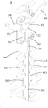
- a foldable mobile terminal includes a flexible display screen 10, a folding mechanism 20, and a casing assembly 30.
- the casing assembly 30 includes a first casing 31 and a second casing 32, wherein the folding mechanism 20 is coupled between the first casing 31 and the second casing 32, and the flexible display screen 10 is disposed at the first casing 31 and the second casing On the housing 32.
- the foldable mobile terminal shown in FIG. 1 is in an unfolded state, and the first housing 31 and the second housing 32 are symmetrical with respect to the folding mechanism 20. As shown in FIG.
- the flexible display screen 10 is outside the mobile terminal.
- the extension length of the shell assembly 30 toward one side of the flexible display screen 10 (the dimension in the X-axis direction in FIG. 1) and the extension length on the side facing away from the flexible display screen 10 (Fig. 1 has the same dimension in the X-axis direction, and as shown in FIG. 19, the shell assembly 30 has its own thickness (the dimension in the Y-axis direction in FIG. 1), and in the folded state, the shell assembly 30 faces the flexible display screen 10.
- the extension length of the side is greater than the extension length of the side facing away from the flexible display screen 10.
- the first housing 31 includes a first front case 311 and a first rear case 312 that are coupled to each other
- the second case 32 includes a second front case 321 and a second rear case 322 that are coupled to each other.
- the combination can be screw lock, bonding, welding, and the like.
- the flexible display screen 10 is disposed on the first front case 311 and the second front case 321 .
- the display area of the flexible display screen 10 may be rectangular or rounded rectangular in the unfolded state.
- the first front case 311 and the first rear case 312 have a certain spacing in the Y-axis direction.
- the second front case 321 and the second rear case 322 also have a certain spacing in the Y-axis direction.
- the spacing provides a space for placing components such as a power module, a communication module, and the like, and also provides a space required for the folding mechanism 20 to slide and contract with respect to the first housing 31 and the second housing 32.
- the first housing 31 and the second housing 32 also have a certain interval in the X-axis direction, and the folding mechanism 20 is disposed in the space between the first housing 31 and the second housing 32 in the X-axis direction. And at least part of the structure of the folding mechanism 20 is received in the first housing 31 and the second housing 32.
- the distance between the first housing 31 and the second housing 32 in the X-axis direction may change during the rotation of the first housing 31 and the second housing 32 about the folding mechanism 20, and thus the first housing 31.
- the folding mechanism 20 is retracted into the first housing 31 and the second housing 32 to varying degrees. 4 and 5, the folding mechanism 20 includes a first rotating assembly 50 and a second rotating assembly 60.
- the first rotating component 50 is coupled to the first housing 31.
- the first rotating component 50 is at least partially received in the first housing 31 and slidably expands and contracts relative to the first housing 31.
- the second rotating component 60 and the second housing The second rotating component 60 is at least partially received in the second housing 32 and is slidable and contractable relative to the second housing 32.
- the first rotating component 50 is slidably extended relative to the first housing 31 and the second rotating component 60.
- the first housing 31 and the second housing 32 are adapted to accommodate the difference in length generated when switching between the unfolded state and the folded state with respect to the sliding expansion and contraction of the second housing 32.
- first rotating assembly 50 and the second rotating assembly 60 are identical in structure, and the first rotating assembly 50 and the second rotating assembly 60 are along a central axis between the first rotating assembly 50 and the second rotating assembly 60.
- II (Fig. 5) is symmetrically distributed, and the symmetric opening and closing of the first housing 31 and the second housing 32 along the central axis II can be achieved by the symmetrical arrangement of the first rotating assembly 50 and the second rotating assembly 60.
- the first rotating assembly 50 includes a first sliding plate 51, a first rotating shaft 53, and a first link 54.
- the first rotating shaft 53 is disposed on the first sliding plate 51.
- the first end 541 of the first connecting rod 54 is slidably hinged on the first rotating shaft 53, and the second end 542 of the first connecting rod 54 is first and second.
- the housing 31 is rotatably coupled.
- the first sliding plate 51 is at least partially received in the first casing 31 and can slide and contract relative to the first casing 31.
- the first sliding plate 51 and the first rotating shaft 53 slide and contract together with respect to the first housing 31, and the second end 542 of the first connecting rod 54 is opposite.
- the first housing 31 is rotated, and the first end 541 of the first link 54 slides on the first rotating shaft 53 while rotating relative to the first rotating shaft 53.
- the extent of accommodation in the first housing 31 by the first slide 51 varies to accommodate the difference in length produced during the symmetric opening and closing of the first housing 31 and the second housing 32.
- the first sliding plate 51 is provided with two first rotating shafts 53 and two first connecting rods 54, and is vertically symmetrical with respect to the intermediate position in the Z-axis direction of the first sliding plate 51.
- the number of the first rotating shaft 53 and the first connecting rod 54 may be one or more, and the different number of the first rotating shaft 53 and the first connecting rod 54 may implement the first sliding plate 51 relative to the first The sliding movement of a casing 31 is performed.
- the second rotating assembly 60 includes a second sliding plate 61, a second rotating shaft 63, and a second connecting rod 64.
- the second rotating shaft 63 is disposed on the second sliding plate 61.
- the first end 641 of the second connecting rod 64 is slidably hinged on the second rotating shaft 63, and the second end 642 and the second end of the second connecting rod 64 are second and second.
- the housing 32 is rotatably coupled.
- the second sliding plate 61 is at least partially received in the second casing 32 and can slide and contract relative to the second casing 32.
- the second sliding plate 61 and the second rotating shaft 63 slide and contract together with respect to the second housing 32, and the second end 642 of the second connecting rod 64 is opposite.
- the second housing 32 is rotated, and the first end 641 of the second link 64 slides on the second rotating shaft 63 while rotating relative to the second rotating shaft 63.
- the degree of change in the second housing 32 by the second slider 61 is varied to accommodate the difference in length produced during the symmetric opening and closing of the first housing 31 and the second housing 32.
- the second slide plate 61 is provided with two second rotating shafts 63 and two second connecting rods 64, and is vertically symmetric with respect to the intermediate position in the Z-axis direction of the second sliding plate 61.
- the number of the second rotating shaft 63 and the second connecting rod 64 may be one or more, and the different number of the second rotating shaft 63 and the second connecting rod 64 may implement the second sliding plate 61 relative to the first The sliding and contracting of the two housings 32.
- the folding mechanism 20 further includes a linkage 22 connecting the first rotating shaft 53 and the second rotating shaft 63.
- the linking member 22 is provided with a first through hole 221 and a second through hole. 222, the first rotating shaft 53 is disposed in the first through hole 221, and the second rotating shaft 63 is disposed in the second through hole 222.
- the linkage 22 is interlocked with the first end 541 of the first link 54 and the first end 641 of the second link 64, that is, by the connection of the linkage 22, the first end 541 of the first link 54 is on the first shaft 53
- the upper slide can drive the sliding of the first end 641 of the second link 64 on the second shaft 63, and vice versa.
- the linkage 22 synchronizes the movement of the first link 54 slidably hinged on the first shaft 53 with the second link 64 slidably hinged on the second shaft 63, that is, the first slider 51 is opposite to the first housing
- the sliding expansion and contraction of the body 31 and the sliding expansion and contraction of the second sliding plate 61 with respect to the second housing 32 are better to achieve symmetrical opening and closing of the first housing 31 and the second housing 32.
- the link member 22 may be made of a metal material or a plastic material.
- the function of the linkage 22 can be implemented by other components, such as an element that achieves sliding articulation of the first link 54 and the first shaft 53 and a sliding of the second link 64 and the second shaft 63.
- the hinged elements are integrally provided, and the first link 54 that is slidably hinged on the first shaft 53 and the second link 64 that is slidably hinged on the second shaft 63 can also be slid by the integrally provided slidable hinged element. Motion synchronization.
- the first rotating component 50 further includes a first slider 52 , and the sliding of the first link 54 and the first rotating shaft 53 is realized by the first sliding block 52 . Hinged.
- the first slider 52 is slidably sleeved on the first rotating shaft 53 , and the first end 541 of the first connecting rod 54 is rotatably connected to the first sliding block 52 .
- the first slider 52 includes two sleeves 521 and a connecting arm 522 connected between the sleeves 521.
- the first rotating shaft 53 passes through the sleeve 521 of the first slider 52, A slider 52 can slide on the first rotating shaft 53 or can rotate relative to the first rotating shaft 53.
- the first end 541 of the first link 54 is rotatably coupled to the connecting arm 522 of the first slider 52.
- a first positioning hole 523 is disposed on the connecting arm 522 of the first slider 52.
- the first end 541 of the first connecting rod 54 is provided with a first positioning post 543, and the first positioning post 543 is inserted in the first A positioning hole 523 is included.
- the second rotating assembly 60 further includes a second slider 62 through which the sliding engagement of the second link 64 and the second rotating shaft 63 is achieved.
- the second slider 62 is slidably sleeved on the second rotating shaft 63, and the first end 641 of the second connecting rod 64 is rotatably connected with the second sliding block 62.
- the second slider 62 includes two sleeves 621 and a connecting arm 622 connected between the sleeves 621.
- the second rotating shaft 63 passes through the sleeve 621 of the second slider 62.
- the two sliders 62 can slide on the second rotating shaft 63 or can rotate relative to the second rotating shaft 63.
- the first end 641 of the second link 64 is rotatably coupled to the connecting arm 622 of the second slider 62.
- a second positioning hole 623 is disposed on the connecting arm 622 of the second slider 62.
- the first end 641 of the second connecting rod 64 is provided with a second positioning post 643, and the second positioning post 643 is inserted in the Two positioning holes 623.
- the linkage 22 includes a first arm portion 223 that defines the first through hole 221 and a second arm portion 224 that defines the second through hole 222.
- the first arm portion 223 is disposed at the first Between the two sleeves 521 of the slider 52, the second arm portion 224 is disposed between the two sleeves 621 of the second slider 62, and the first rotating shaft 53 is disposed in the first through hole 221, The second rotating shaft 63 is disposed in the second through hole 222.
- the link member 22 serves as a connection medium for the first slider 52 and the second slider 62 so that the sliding of the first slider 52 on the first rotating shaft 53 and the sliding of the second slider 62 in the second rotating shaft 63 can be synchronized.
- the first rotating component 50 further includes a first bracket 56, and the first rotating shaft 53 is disposed at the first through the first bracket 56.
- the first bracket 56 can be fixed on the first sliding plate 51 by screwing.
- the first rotating shaft 53 is disposed on the first bracket 56
- the first sliding block 52 is disposed between the first bracket 56 and the first sliding plate 51 .
- the rotation connection of the second end 542 of the first link 54 with the first housing 31 may be implemented by the second end 542 of the first link 54 being rotatably connected with the first front case 311, or the first link
- the second end 542 of the 54 is rotatably coupled to the first rear housing 312, or the second end 542 of the first connecting rod 54 is simultaneously rotatably coupled to the first front housing 311 and the first rear housing 312.
- the first front housing 311 is provided with a first connecting hole 313
- the second end 542 of the first connecting rod 54 is provided with a first connecting post. 544.
- the first connecting post 544 is inserted in the first connecting hole 313. Further, as shown in FIG.
- the first rotating assembly 50 further includes a first pressing piece 55, and the first pressing piece 55 is connected to the first front case 311, and the first pressing piece 55 is further connected. Limiting the first link 54 causes the first link 54 to be located between the first pressing piece 55 and the first front case 311.
- the second rotating component 60 further includes a second bracket 66, and the second rotating shaft 63 is disposed in the second by the second bracket 66. Skateboard 61. Further, the second bracket 66 can be fixed on the second sliding plate 61 by screwing. The second rotating shaft 63 is disposed on the second bracket 66, and the second slider 62 is disposed between the second bracket 66 and the second sliding plate 61.
- the second bracket 66 By providing the second bracket 66, the relative movement between the first end 641 of the second slider 62 and the second link 64 and the second rotating shaft 63 can be restricted to the second bracket 66 and the second sliding plate 61. In the space, the first end 641 of the second link 64 is prevented from being disengaged from the second slider 62.
- the rotation connection of the second end 642 of the second link 64 and the second housing 32 may be implemented by the second end 642 of the second link 64 being rotatably connected with the second front case 321 or the second link
- the second end 642 of the 64 is rotatably coupled to the second rear case 322, or the second end 642 of the second link 64 is simultaneously rotatably coupled to the second front case 321 and the second rear case 322.
- the second front housing 321 is provided with a second connecting hole 323
- the second end 642 of the second connecting rod 64 is provided with a second connecting post.
- the second connecting post 644 is inserted into the second connecting hole 323.
- the second rotating assembly 60 further includes a second pressing piece 65.
- the second pressing piece 65 is coupled to the second front case 321 and the second pressing piece 65 is connected.
- the second link 64 is limited to position the second link 64 between the second tab 65 and the second front case 321.
- the folding mechanism 20 further includes a boss 24 disposed at both ends of the first rotating shaft 53 and the second rotating shaft 63.
- the sleeve 24 secures the first shaft 53 to the first bracket 56 while also securing the second shaft 63 to the second bracket 66.
- the number of the first bracket 56 and the second bracket 66 is the same as the number of the first rotating shaft 53 and the second rotating shaft 63.
- the number of the first bracket 56 and the second bracket 66 are two, and each of the first brackets 56 is disposed at a corresponding end of the first sliding plate 51 along the Z-axis direction, and each of the second brackets 66 is disposed. At the corresponding end of the second slide plate 61 in the Z-axis direction.
- the folding mechanism 20 further includes a support strip 26 disposed between the first rotating assembly 50 and the second rotating assembly 60.
- a support strip 26 is used to support the flexible display screen 10.
- the support bar 26 may have a certain extension length in the Z-axis direction to be disposed between the slits of the first slider 51 and the second slider 61.
- the support strips 26 may also extend between the slots of the first bracket 56 and the second bracket 66.
- the support bar 26 can support the flexible display screen 10 together with the first slide plate 51, the second slide plate 61, the first bracket 56, the second bracket 66, the first front case 311, and the second front case 321 .
- the connecting member 22 is provided with a receiving groove 226 , and at least a portion of the supporting strip 26 is received in the receiving groove 226 .
- the linkage 22 includes a connecting portion 225 that connects the first arm portion 223 and the second arm portion 224, and the receiving groove 226 is disposed on the connecting portion 225.
- the sleeve 24 is also provided with a receiving groove 241 , and at least part of the structure of the supporting strip 26 is received in the receiving groove 241 .
- the connection of the support bar 26 to the sleeve 24 and/or the linkage 22 can be achieved by welding or the like.
- the top surface 261 of the support strip 26 faces the flexible display screen 10 and is curved.
- the foldable mobile terminal is in the half-folded state shown in FIG. 24 or the folded state shown in FIG. 25, since the support bar 26 has a curved surface, the folding process of the first housing 31 and the second housing 32 can be avoided.
- the curvature of the middle contour is abruptly changed to better support the flexible display screen 10.
- the first rotating component 50 further includes a first elastic piece 57 disposed on the first sliding plate 51, and the first elastic piece 57 is in the first connection.
- the two extreme positions of the sliding direction of the first end 541 of the rod 54 are respectively set to the first engagement positions 571.
- the first elastic piece 57 is fixed to the first sliding plate 51 by the first bracket 56, and the first elastic piece 57 is disposed in the first bracket 56.
- the two first engaging positions 571 of the first elastic piece 57 correspond to both ends of the sliding path of the first end 541 of the first link 54 on the first rotating shaft 53.
- a certain degree of interference is formed between the first engagement position 571 and the first end 541 of the first link 54 such that the first engagement position 571 forms a certain clamping force on the first end 541 of the first link 54.
- the position of the first link 54 is prevented from being arbitrarily changed, so that the position of the first slider 51 relative to the first housing 31 can be stabilized, that is, the foldable mobile terminal can be stably maintained in the folded state or the unfolded state.
- the first positioning post 543 on the first end 541 of the first link 54 extends through opposite sides of the first end 541, wherein one end of the first positioning post 543 and the first slider The first positioning hole 523 on the 52 is engaged, and the other end of the first positioning post 543 is inserted in the first engaging position 571 of the first elastic piece 57.
- the first engaging position 571 sandwiches the first positioning post 543 to form a certain clamping force to the first link 54.
- a first damping position 572 is disposed between the two first engaging positions 571 of the first elastic piece 57, wherein the first end 541 of the first connecting rod 54 is replaced by the first engaging position 571.
- the resistance becomes larger as it slides toward the first damping position 572.
- the resistance becomes larger by the clamping force exerted by the first damping position 572 on the first positioning post 543 being greater than the clamping force applied to the first positioning post 543 by the first engagement position 571.
- the first elastic piece 57 may be a waist circular shape that is open at one end and closed at one end.
- Two first engagement positions 571 are formed at two ends of the first elastic piece 57, and a first damping position 572 is formed in the middle of the first elastic piece 57.
- the gap in the first damping position 572 for the first positioning post 543 is smaller than the gap in the first engaging position 571 for the first positioning post 543 to pass through, and thus leads from the first engaging position 571 to the first damping position.
- the resistance of the first link 54 is increased.
- the first shrapnel 57 can also be in a closed loop.
- the first elastic piece 57 may be in two separate strip shapes, and the two separated strip spring pieces may be fixed at the first end by the first bracket 56 or other components (or other forms).
- different resistances are provided at different positions of the sliding path of the first link 54 along the first rotating shaft 53.
- the first bracket 56 is provided with a first receiving cavity 560 , and the first elastic piece 57 is received in the first receiving cavity 560 .
- the first sliding plate 51 closes the first receiving cavity 560, so that the first elastic piece 57 is fixed in the first receiving cavity 560.
- the first receiving cavity 560 includes two first positioning cavities 561 corresponding to the first engaging positions 571 of the first elastic piece 57, and a first releasing cavity 562 located between the two first positioning cavities 561.
- the space in the first release cavity 562 is larger than the space of the first positioning cavity 561.
- the second rotating assembly 60 further includes a second elastic piece 67 disposed on the second sliding plate 61, and the second elastic piece 67 is in the sliding direction of the first end 641 of the second connecting rod 64.
- the second engagement position 671 is set at each extreme position.
- the second elastic piece 67 is fixed to the second slide plate 61 by the second bracket 66, and the second elastic piece 67 is disposed in the second bracket 66.
- the two second engaging positions 671 of the second elastic piece 67 correspond to both ends of the sliding path of the first end 641 of the second link 64 on the second rotating shaft 63.
- a certain degree of interference is formed between the second engagement position 671 and the first end 641 of the second link 64 such that the second engagement position 671 forms a certain clamping force on the first end 641 of the second link 64.
- the position of the second link 64 is prevented from being arbitrarily changed, so that the position of the second slider 61 relative to the second housing 32 can be stabilized, that is, the foldable mobile terminal can be stably maintained in the folded state or the unfolded state.
- the second positioning post 643 on the first end 641 of the second link 64 extends through opposite sides of the first end 641, wherein one end of the second positioning post 643 and the second slider The second positioning hole 623 on the 62 is engaged, and the other end of the second positioning post 643 is inserted in the second engagement position 671 of the second elastic piece 67.
- the second engaging position 671 sandwiches the second positioning post 643 to form a certain clamping force to the second link 64.
- FIG. 5 shows the folding mechanism 20 in an unfolded state
- the second positioning post 643 formed on the first end 641 of the second link 64 is disposed in one of the first In the second engagement position 671
- FIG. 22 shows the folding mechanism 20 in a folded state
- the second positioning post 643 formed on the first end 641 of the second link 64 is passed through the other second engagement position 671.
- a second damping position 672 is disposed between the two second engaging positions 671 of the second elastic piece 67, wherein the first end 641 of the second connecting rod 64 is replaced by the second engaging position 671.
- the resistance becomes large.
- the increase in resistance can be achieved by the clamping force applied by the second damping position 672 to the second positioning post 643 being greater than the clamping force applied by the second clamping position 671 to the second positioning post 643.
- the second elastic piece 67 may have a waist shape that is open at one end and closed at one end.
- Two second engagement positions 671 are formed at two ends of the second elastic piece 67, and a second damping position 672 is formed at the middle of the second elastic piece 67.
- the gap in the second damping position 672 for the second positioning post 643 is smaller than the gap in the second clamping position 671 for the second positioning post 643 to pass through, so that the second clamping position 671 leads to the second damping position.
- the resistance of the second link 64 is increased.
- the second elastic piece 67 may also have a closed loop shape. Further, in some embodiments, the second elastic piece 67 may be in two separate strip shapes, and the two separated strip spring pieces may be fixed at the second end by the second bracket 66 or other components (or other forms). On the slider 61, different resistances are provided at different positions of the sliding path of the second link 64 along the second rotating shaft 63.
- the second bracket 66 is provided with a second receiving cavity 660 , and the second elastic piece 67 is received in the second receiving cavity 660 .
- the second sliding plate 61 closes the second receiving cavity 660, so that the second elastic piece 67 is fixed in the second receiving cavity 660.
- the second receiving cavity 660 includes two second positioning cavities 661 corresponding to the second engaging positions 671 of the second elastic piece 67, and a second releasing cavity 662 located between the two second positioning cavities 661.
- the space in the second release cavity 662 is larger than the space of the second positioning cavity 661.
- the foldable mobile terminal further includes a connecting piece 70 and two pressing blocks 71.
- the connecting piece 70 spans the first rotating component 50 and the second rotation.
- the assembly 60 and the two ends of the connecting piece 70 are respectively slidably coupled to the first housing 31 and the second housing 32 via a pressing block 71.
- the difference in length difference generated during the rotation of the first housing 31 and the second housing 32 is slid by the first rotation assembly 50 and the second rotation assembly 60 in the folding mechanism 20 relative to the first housing 31 and the second housing 32, respectively.
- the expansion and contraction are absorbed, so that the appearance of the foldable mobile terminal during folding and unfolding is uniform and complete, and by providing the connecting piece 70, the first housing 31 and the second housing 32 can be prevented from being excessively stretched, thereby avoiding the flexible display screen 10. Being stretched causes damage.
- the first end 701 of the connecting piece 70 is provided with a first elongated hole 703, and the second end 702 of the connecting piece 70 is provided with a second elongated hole 704, and the pressing block 71 passes through the first
- the elongated hole 703 is fixedly coupled to the first housing 31, and the other of the pressing blocks 71 is fixedly coupled to the second housing 32 through the second elongated hole 704.
- the connecting piece 70 is relatively pressed along the extending direction of the first and second elongated holes 703, 704.
- the block 71 moves, that is, moves relative to the first and second housings 31, 32.
- the outer ends of the first and second elongated holes 703 of the connecting piece 70 that is, the ends away from the first rotating component 50 and the second rotating component 60, respectively. Abutting the first housing 31 and the second housing 32, the first housing 31 and the second housing 32 cannot continue to be relatively far apart, and the first and second housings 31, 32 are prevented from being excessively stretched.
- the connecting piece 70 can be relatively slid relative to the first and second housings 31 and 32 to The length of the first and second housings 32 is adapted to accommodate the folding process.
- the connecting piece 70 includes two connecting portions 705 at the first end 701 and the second end 702, and a supporting portion 706 connected between the two connecting portions 705 for connecting with the pressing block 71.
- the support portion 706 is used to support the flexible display screen 10.
- the pressing block 71 may be a fastener such as a screw. After the first and second elongated holes 703 and 704 are passed through, the connecting piece 70 is connected to the first housing 31 and the second housing 32.
- the pressing block 71 has a square block shape, is pressed against the first end 701 and the second end 702 of the connecting piece 70, and then passes through the pressing block 71 and the first and second elongated shapes by means of another fastener. The holes 703, 704 are locked to the first and second housings 31, 32.
- a first mating position 314 is formed on the first front case 311, and the pressing block 71 slidably connects the first end 701 of the connecting piece 70 at the first mating position 314 of the first front case 311.
- a second mating position 324 is formed on the second front housing 321 , and the other pressing block 71 slidably connects the second end 702 of the connecting piece 70 to the second mating position 324 of the second front housing 321 .
- the support portion 706 forms a bend with the intersection of the two connecting portions 705.
- the first mating position 314 and the second mating position 324 are each formed with a recess to match the bend on the tab 70, and also to accommodate the corresponding press block 71.
- the connecting piece 70 is provided with mutually spaced through holes 700.
- the perforations 700 are disposed on the support portion 706.
- the perforations 700 make the tab 70 easier to bend, allowing the tab 70 to better conform to the first rotating assembly 50 and the second rotating assembly 60, avoiding connections.
- the sheet 70 produces wrinkles that affect the support effect on the flexible display screen 10.
- the support portion 706 is further provided with a fixing structure 707 connected to the support bar 26.
- the fixing structure 707 may be a soldering hole. After the connecting piece 70 spans the supporting strip 26, it may be fixedly connected to the supporting strip 26 by welding.
- connecting pieces 70 there are two connecting pieces 70. It can be understood that the number of connecting pieces 70 in other embodiments can be increased or decreased as needed.
- the foldable mobile terminal further includes a decorative block 72 located at two ends of the folding mechanism 20 in the Z-axis direction, and located in the first housing 31 and the second At the gap between the housings 32, the end structure for shielding the folding mechanism 20 prevents the appearance from affecting the appearance.
- the first front housing 311 is provided with a first connecting position 315
- the second front housing 321 is provided with a second connecting position 325
- the decorative block 72 and the first front housing 311 are respectively provided.
- a connection position 315 and a second connection position 325 of the second front case 321 form a connection and are located at both ends of the first slide plate 51 and the second slide plate 61 in the Z-axis direction.
- the decorative block 72 is generally flat toward one side surface of the flexible display screen 10 to facilitate mounting the flexible display screen 10.
- a side surface of the decorative block 72 facing away from the flexible display screen 10 forms a connection structure with the first front case 311 and the second front case 321 , such as a stud 721 .
- a plurality of ribs 722 are also formed on a side surface of the decorative block 72 facing away from the flexible display screen 10.
- a first gap 316 is provided on the first housing 31.
- the first notch 316 is disposed on a side of the first front case 311 adjacent to the first rotating assembly 50.
- the first slider 51 is provided with a first latch 511 corresponding to the first notch 316 of the first housing 31.
- the first slider 51 includes a first substrate 510 formed on the first substrate 510.
- the first substrate 510 is located between the first front case 311 and the first rear case 312 and is slidable and contractible between the first front case 311 and the first rear case 312.
- the first latch 511 is in the same plane as the first front housing 311, which plane is parallel to the plane defined by the XZ axis.
- the first latching teeth 511 are in the same plane as the first front housing 311 for supporting the flexible display screen 10 in common.
- a corresponding first notch is also formed between two adjacent first latching teeth 511 on the first sliding plate 51, and a corresponding one is formed between two adjacent first notches 316 on the first front casing 311.
- the first latch 511 on the first slider 51 corresponds to the first notch 316 on the first front case 311, and the first notch on the first slide 51 corresponds to the first latch on the first front case 311.
- a second gap 326 is formed on the second housing 32.
- the second notch 326 is disposed on a side of the second front case 321 adjacent to the second rotating assembly 60.
- the second slider 61 is provided with a second latch 611 corresponding to the second notch 326 of the second housing 32.
- the second slider 61 includes a second substrate 610, and the second tab 611 is formed on the second substrate 610.
- the second substrate 610 is located between the second front case 321 and the second rear case 322 and is slidable and contractible between the second front case 321 and the second rear case 322.
- the second latching teeth 611 are in the same plane as the second front housing 321 which is parallel to the plane defined by the XZ axis for collectively supporting the flexible display screen 10.
- a corresponding second notch is also formed between two adjacent second latching teeth 611 on the second sliding plate 61, and correspondingly formed between two adjacent second notches 326 on the second front casing 321 a second card tooth.
- the second latch 611 on the second slide 61 corresponds to the second notch 326 on the second front case 321
- the second notch on the second slide 61 corresponds to the second latch on the second front case 321 .
- the first latching teeth 511 on the first sliding plate 51 are connected to each other at one end away from the first housing 31 to form a first supporting beam 513, and the second sliding plate 61 is second.
- the ends of the latching teeth 611 away from the second housing 32 are interconnected to form a second support beam 613, which is at least partially placed on the first support beam 513 and the second support beam 613.
- the foldable mobile terminal further includes a first roller 58 and a first spring 59, and the first roller 58 and the first spring 59 are disposed in the first rotating assembly 50 and the first housing 31.
- a first groove 514 is disposed on the first rotating component 50. When the first rotating component 50 slides and contracts relative to the first housing 31, the first roller 58 can enter or disengage the first groove 514.
- the foldable mobile terminal is made to have a feeling of folding in place.
- the first roller 58 and the first spring 59 can be disposed between the first slider 51 and the first rear housing 312. In still other embodiments, the first roller 58 and the first spring 59 may be disposed between the first slider 51 and the first front case 311.
- the first groove 514 is formed on a sidewall of the first latch 511 of the first slider 51 , and the first recess 514 faces the first substrate. Adjacent to a first latch 511 on the 510.
- the first notch 316 is recessed away from the corresponding first latch 511 to form a first cavity 317, and the first roller 58 and the first spring 59 are received in the Inside the first cavity 317.
- the first spring 59 abuts the first roller 58 to at least partially expose the first roller 58 to the first cavity 317, thereby causing the first roller 58 to elastically resist the sidewall of the first latch 511.
- the extending length of the first latching teeth 511 forming the first recess 514 toward the first housing 31 is greater than the extending length of the other first latching teeth 511 toward the first housing 31.
- the first roller 58 and the first spring 59 include at least two groups, and opposite sidewalls of the first latch 511 form a first match with the first roller 58. Groove 514.
- the first notch 316 is also recessed from the corresponding first latch 511 to form two first cavities 317, each of the first cavities 317 is for accommodating a set of first rollers 58 and A spring 59.
- the two extreme positions on the sidewall of the first latch 511 corresponding to the first slide 51 form two first recesses 514.
- one of the extreme positions is located at the end of the first latch 511 near the first housing 31, and the other extreme position is located at the junction of the first latch 511 and the first cross member 513.
- the first rollers 58 respectively enter the first recesses 514 at the two extreme positions, thereby creating a feeling of being deployed into position or folded into place.
- the foldable mobile terminal further includes a second roller 68 and a second spring 69 disposed between the second rotating assembly 60 and the second housing 32, the second rotation A second recess 614 is disposed on the assembly 60.
- the second roller 68 can enter or disengage the second recess 614 such that the foldable mobile terminal has an unfolded The feeling of experience in place.
- the second roller 68 and the second spring 69 can be disposed between the second slider 61 and the second rear housing 322.
- the second roller 68 and the second spring 69 may be disposed between the second slider 61 and the second front case 321.
- the second groove 614 is formed on one sidewall of the second latch 611 of the second slide 61 , and the second recess 614 faces the second substrate. Adjacent to a second latch 611 on 610.
- the second notch 326 is recessed away from the corresponding second latching tooth 611 to form a second cavity 327, and the second roller 68 and the second spring 69 are received in the Inside the second cavity 327.
- the second spring 69 abuts against the second roller 68 to at least partially expose the second roller 68 to the second cavity 327, thereby causing the second roller 68 to elastically resist the sidewall of the second latch 611.
- extension length of the second latching teeth 611 forming the second recess 614 toward the second housing 32 is greater than the extension length of the other second latching teeth 611 toward the second housing 32.
- the second roller 68 and the second spring 69 comprise at least two groups, and the opposite side walls of the second latch 611 form a second matching with the second roller 68. Groove 614.
- the second notch 326 is also recessed away from the corresponding second latch 611 to form two second cavities 327, each of the second cavities 327 is for accommodating a set of second rollers 68 and Two springs 69.
- the two extreme positions on the sidewall of the second latch 611 corresponding to the second sled 61 form two second recesses 614.
- one of the extreme positions is located at the end of the second latch 611 near the second housing 32, and the other extreme position is located at the junction of the second latch 611 and the second cross member 613.
- the second rollers 68 respectively enter the second recesses 614 in the two extreme positions, thereby creating a feeling of being deployed into position or folded into place.
Abstract
A foldable mobile terminal, comprising: a flexible display screen (10); a first housing (31) and a second housing (32), the flexible display screen being provided on the first housing and the second housing; and a folding mechanism (20) comprising a first rotating assembly (50) connected to the first housing and a second rotating assembly (60) connected to the second housing. The first and second rotating assemblies both comprise sliding plates (51, 61), rotating shafts (53, 63), and connecting rods (54, 64). The sliding plates are at least partially received in the housings, and can extend or retract with respect to the housings in a sliding manner. First ends of the connecting rods are slidably and hingedly connected to the rotating shafts, and second ends are rotatably connected to the housings.
Description
本发明涉及电子设备技术领域,特别是涉及一种可折叠移动终端。The present invention relates to the field of electronic device technologies, and in particular, to a foldable mobile terminal.
柔性显示屏具有可弯折的性能,这就使得搭载柔性显示屏的智能移动终端,例如智能手机,在折叠和展开状态之间实现切换成为可能。移动终端在展开状态时面向用户的一侧和背向用户的一侧长度相等,然而在折叠状态时,却因移动终端本身的厚度导致原来长度相等的两侧存在差值,这就要求可折叠移动终端需要适应不同状态时两侧的长度差异变化。The flexible display has bendable performance, which makes it possible to switch between folded and unfolded smart mobile terminals equipped with flexible displays, such as smartphones. When the mobile terminal is in the unfolded state, the side facing the user and the side facing away from the user are equal in length. However, in the folded state, there is a difference between the two sides of the original length due to the thickness of the mobile terminal itself, which requires folding. The mobile terminal needs to adapt to changes in the length difference between the two sides in different states.
发明内容Summary of the invention
本发明解决的一个技术问题是如何使可折叠移动终端适应于不同状态下因自身厚度而产生的相对两个侧面的尺寸变化。One technical problem addressed by the present invention is how to adapt the foldable mobile terminal to dimensional changes of the opposite sides due to its own thickness in different states.
一种可折叠移动终端,包括:A foldable mobile terminal comprising:
柔性显示屏;Flexible display
壳组件,包括第一壳体和第二壳体,所述柔性显示屏设置在第一壳体和第二壳体上;及a housing assembly including a first housing and a second housing, the flexible display screen being disposed on the first housing and the second housing;
折叠机构,包括与第一壳体连接的第一转动组件和与第二壳体连接的第二转动组件,所述第一转动组件包括第一滑板、第一转轴和第一连杆,所述第一滑板至少部分的收容在第一壳体内并可相对第一壳体滑动伸缩,所述第一转轴设置在第一滑板上,所述第一连杆的第一端滑动铰接在第一转轴上,第二端与第一壳体转动连接;所述第二转动组件包括第二滑板、第二转轴和第二连杆,所述第二滑板至少部分的收容在第二壳体内并可相对第二壳体滑动伸缩,所述第二转轴设置在第二滑板上,所述第二连杆的第一端滑动铰接在第二转轴上,第二端与第二壳体转动连接。a folding mechanism comprising a first rotating component coupled to the first housing and a second rotating component coupled to the second housing, the first rotating assembly including a first sliding plate, a first rotating shaft and a first link, The first sliding plate is at least partially received in the first housing and is slidable and contractable relative to the first housing, the first rotating shaft is disposed on the first sliding plate, and the first end of the first connecting rod is slidably hinged on the first rotating shaft The second end is rotatably coupled to the first housing; the second rotating assembly includes a second sliding plate, a second rotating shaft and a second connecting rod, and the second sliding plate is at least partially received in the second housing and is opposite The second housing is slidably telescoped, the second rotating shaft is disposed on the second sliding plate, the first end of the second connecting rod is slidably hinged on the second rotating shaft, and the second end is rotatably coupled to the second housing.
本发明的一个实施例的一个技术效果是通过折叠机构可吸收可折叠移动终端在折叠和展开过程中产生的相对两个侧面的尺寸差异变化,并且可折叠移动终端具有外观完整性。One technical effect of one embodiment of the present invention is that the folding mechanism can absorb the dimensional difference variations of the opposite sides produced by the foldable mobile terminal during folding and unfolding, and the foldable mobile terminal has appearance integrity.
图1为本发明一个实施例提供的可折叠移动终端处于展开状态的立体结构示意图。FIG. 1 is a schematic perspective structural view of a foldable mobile terminal in an unfolded state according to an embodiment of the present invention.
图2为图1所示可折叠移动终端的分解示意图。2 is an exploded perspective view of the foldable mobile terminal shown in FIG. 1.
图3为图1所示可折叠移动终端的另一角度的分解示意图。3 is an exploded perspective view of another angle of the foldable mobile terminal shown in FIG. 1.
图4为本发明一个实施例提供的可折叠移动终端内的折叠机构处于展开状态的立体结构示意图。FIG. 4 is a schematic perspective structural view of a folding mechanism in a foldable mobile terminal in an unfolded state according to an embodiment of the present invention.
图5为图4所示折叠机构的主视示意图。Figure 5 is a front elevational view of the folding mechanism of Figure 4.
图6为图4所示折叠机构去除部分结构后的立体结构示意图。Figure 6 is a perspective view showing the structure of the folding mechanism shown in Figure 4 after removing a part of the structure.
图7为图4所示折叠机构的分解示意图。Figure 7 is an exploded perspective view of the folding mechanism of Figure 4.
图8为图7中部分结构的进一步分解示意图。Figure 8 is a further exploded perspective view of a portion of the structure of Figure 7.
图9为图7中部分结构的另一视角的分解示意图。Figure 9 is an exploded perspective view of another perspective of the structure of Figure 7.
图10为本发明一个实施例提供的可折叠移动终端去除柔性显示屏后的立体结构示意图。FIG. 10 is a schematic perspective structural view of a foldable mobile terminal after removing a flexible display screen according to an embodiment of the present invention.
图11为图10所示结构的部分主视示意图。Figure 11 is a partial front elevational view of the structure of Figure 10.
图12为图11中线A-A的剖视示意图。Figure 12 is a cross-sectional view of the line A-A of Figure 11.
图13为图10所示结构的剖视示意图,且视角为后视。Figure 13 is a cross-sectional view of the structure shown in Figure 10, and the viewing angle is a rear view.
图14为图11所示结构去除折叠机构中的部分元件后的示意图。Figure 14 is a schematic view of the structure of Figure 11 after removing some of the components of the folding mechanism.
图15为图14的后视图。Figure 15 is a rear elevational view of Figure 14.
图16为折叠机构中的弹片的结构示意图。Figure 16 is a schematic view showing the structure of the elastic piece in the folding mechanism.
图17为装饰块的结构示意图。Figure 17 is a schematic view showing the structure of a decorative block.
图18为装饰块的另一视角的结构示意图。Figure 18 is a schematic view showing the structure of another view of the decorative block.
图19为本发明一个实施例提供的可折叠移动终端处于折叠状态的立体结构示意图。FIG. 19 is a schematic perspective structural view of a foldable mobile terminal in a folded state according to an embodiment of the present invention.
图20为图19所示可折叠移动终端去除柔性显示屏后的立体结构示意图。FIG. 20 is a schematic perspective structural view of the foldable mobile terminal shown in FIG. 19 after the flexible display screen is removed.
图21为图4所示折叠机构处于折叠状态的立体结构示意图。Figure 21 is a perspective view showing the folding mechanism of Figure 4 in a folded state.
图22为图21所示折叠机构的主视示意图。Figure 22 is a front elevational view of the folding mechanism of Figure 21;
图23为本发明一实施例提供的可折叠移动终端处于展开状态的部分结构剖视示意图。FIG. 23 is a cross-sectional view showing a portion of a foldable mobile terminal in an unfolded state according to an embodiment of the present invention.
图24为本发明一实施例提供的可折叠移动终端处于半展开状态(或半折叠状态)的部分结构剖视示意图。图25为本发明一实施例提供的可折叠移动终端处于折叠状态的剖视示意图。24 is a cross-sectional view showing a portion of a foldable mobile terminal in a semi-expanded state (or a half-folded state) according to an embodiment of the present invention. FIG. 25 is a cross-sectional view showing a foldable mobile terminal in a folded state according to an embodiment of the present invention.
如图1、图2、图3和图4中所示,本发明一实施例提供的可折叠移动终端包括柔性显示屏10、折叠机构20和壳组件30。壳组件30包括第一壳体31和第二壳体32,其中折叠机构20连接在第一壳体31与第二壳体32之间,柔性显示屏10设置在第一壳体31与第二壳体32上。图1所示可折叠移动终端处于展开状态,第一壳体31、第二壳体32相对折叠机构20对称。如图19所示,当第一壳体31、第二壳体32相对折叠机构20转动处于完全折叠状态时,柔性显示屏10在移动终端的外侧。如图1所示,在展开状态时,壳组件30朝向柔性显示屏10的一侧的延伸长度(图1中X轴方向的尺度)与背向柔性显示屏10的一侧的延伸长度(图1中X轴方向的尺度)相同,而如图19所示,壳组件30因自身存在厚度(图1中Y轴方向的尺度),在折叠状态时,壳组件30朝向柔性显示屏10的一侧的延伸长度大于背向柔性显示屏10的一侧的延伸长度,通过设置折叠机构20可使第一壳体31与第二壳体32适应在展开状态和折叠状态之间切换时所产生的长度差异。As shown in FIG. 1, FIG. 2, FIG. 3 and FIG. 4, a foldable mobile terminal according to an embodiment of the present invention includes a flexible display screen 10, a folding mechanism 20, and a casing assembly 30. The casing assembly 30 includes a first casing 31 and a second casing 32, wherein the folding mechanism 20 is coupled between the first casing 31 and the second casing 32, and the flexible display screen 10 is disposed at the first casing 31 and the second casing On the housing 32. The foldable mobile terminal shown in FIG. 1 is in an unfolded state, and the first housing 31 and the second housing 32 are symmetrical with respect to the folding mechanism 20. As shown in FIG. 19, when the first housing 31 and the second housing 32 are rotated in a fully folded state with respect to the folding mechanism 20, the flexible display screen 10 is outside the mobile terminal. As shown in FIG. 1, in the unfolded state, the extension length of the shell assembly 30 toward one side of the flexible display screen 10 (the dimension in the X-axis direction in FIG. 1) and the extension length on the side facing away from the flexible display screen 10 (Fig. 1 has the same dimension in the X-axis direction, and as shown in FIG. 19, the shell assembly 30 has its own thickness (the dimension in the Y-axis direction in FIG. 1), and in the folded state, the shell assembly 30 faces the flexible display screen 10. The extension length of the side is greater than the extension length of the side facing away from the flexible display screen 10. By providing the folding mechanism 20, the first housing 31 and the second housing 32 can be adapted to be switched between the unfolded state and the folded state. Length difference.
所述第一壳体31包括互相结合的第一前壳311和第一后壳312,所述第二壳体32包括互相结合的第二前壳321和第二后壳322。结合的方式可以为螺锁、粘接、焊接等。所述柔性显示屏10设置在第一前壳311和第二前壳321上。所述柔性显示屏10的显示区域在展开状态下可以是呈矩形状或圆角矩形状。第一前壳311和第一后壳312之间在Y轴方向上具有一定的间距,同样,第二前壳321和第二后壳322之间在Y轴方向上也具有一定的间距,此间距提供放置电源模组、通信模组等零部件的空间,同时还提供折叠机构20相对第一壳体31、第二壳体32滑动伸缩所需的空间。The first housing 31 includes a first front case 311 and a first rear case 312 that are coupled to each other, and the second case 32 includes a second front case 321 and a second rear case 322 that are coupled to each other. The combination can be screw lock, bonding, welding, and the like. The flexible display screen 10 is disposed on the first front case 311 and the second front case 321 . The display area of the flexible display screen 10 may be rectangular or rounded rectangular in the unfolded state. The first front case 311 and the first rear case 312 have a certain spacing in the Y-axis direction. Similarly, the second front case 321 and the second rear case 322 also have a certain spacing in the Y-axis direction. The spacing provides a space for placing components such as a power module, a communication module, and the like, and also provides a space required for the folding mechanism 20 to slide and contract with respect to the first housing 31 and the second housing 32.
第一壳体31和第二壳体32之间在X轴方向上也具有一定间距,折叠机构20设置在第一壳体31和第二壳体32之间于X轴方向上的间距内,且折叠机构20的至少部分结构容置在第一壳体31和第二壳体32内。第一壳体31和第二壳体32之间于X轴方向上的间距在第一壳体31、第二壳体32绕折叠机构20转动的过程中会发生变化,因而在第一壳体31、第二壳体32绕折叠机构20转动的过程中,折叠机构20不同程度的缩进第一壳体31和第二壳体32内。同时参考图4和图5,折叠机构20包括第一转动组件50和第二转动组件60。第一转动组件50与第一壳体31连接,第一转动组件50至少部分的收容在第一壳体31内并可相对第一壳体31滑动伸缩,第二转动组件60与第二壳体32连接,第二转动组件60至少部分的收容在第二壳体32内并可相对第二壳体32滑动伸缩,通过第一转动组件50相对第一壳体31滑动伸缩和第二转动组件60相对第二壳体32滑动伸缩,可使第一壳体31与第二壳体32适应在展开状态和折叠状态之间切换时所产生的长度差异。The first housing 31 and the second housing 32 also have a certain interval in the X-axis direction, and the folding mechanism 20 is disposed in the space between the first housing 31 and the second housing 32 in the X-axis direction. And at least part of the structure of the folding mechanism 20 is received in the first housing 31 and the second housing 32. The distance between the first housing 31 and the second housing 32 in the X-axis direction may change during the rotation of the first housing 31 and the second housing 32 about the folding mechanism 20, and thus the first housing 31. During the rotation of the second housing 32 about the folding mechanism 20, the folding mechanism 20 is retracted into the first housing 31 and the second housing 32 to varying degrees. 4 and 5, the folding mechanism 20 includes a first rotating assembly 50 and a second rotating assembly 60. The first rotating component 50 is coupled to the first housing 31. The first rotating component 50 is at least partially received in the first housing 31 and slidably expands and contracts relative to the first housing 31. The second rotating component 60 and the second housing The second rotating component 60 is at least partially received in the second housing 32 and is slidable and contractable relative to the second housing 32. The first rotating component 50 is slidably extended relative to the first housing 31 and the second rotating component 60. The first housing 31 and the second housing 32 are adapted to accommodate the difference in length generated when switching between the unfolded state and the folded state with respect to the sliding expansion and contraction of the second housing 32.
一实施例中,第一转动组件50和第二转动组件60的结构相同,且第一转动组件50和第二转动组件60沿着第一转动组件50和第二转动组件60之间的中轴线I-I(图5)呈对称分布,通过第一转动组件50和第二转动组件60的对称设置,可实现第一壳体31和第二壳体32沿着中轴线I-I的对称开合。In one embodiment, the first rotating assembly 50 and the second rotating assembly 60 are identical in structure, and the first rotating assembly 50 and the second rotating assembly 60 are along a central axis between the first rotating assembly 50 and the second rotating assembly 60. II (Fig. 5) is symmetrically distributed, and the symmetric opening and closing of the first housing 31 and the second housing 32 along the central axis II can be achieved by the symmetrical arrangement of the first rotating assembly 50 and the second rotating assembly 60.
同时参考图4、图5、图6和图7,所述第一转动组件50包括第一滑板51、第一转轴53和第一连杆54。所述第一转轴53设置在第一滑板51上,所述第一连杆54的第一端541滑动铰接在第一转轴53上,所述第一连杆54的第二端542与第一壳体31转动连接。所述第一滑板51至少部分的收容在第一壳体31内并可相对第一壳体31滑动伸缩。第一壳体31和第二壳体32对称开合的过程中,所述第一滑板51和第一转轴53一起相对第一壳体31滑动伸缩,第一连杆54的第二端542相对第一壳体31转动,第一连杆54的第一端541在第一转轴53上滑动,同时相对第一转轴53转动。通过第一滑板51收容在第一壳体31内的程度变化,以适应第一壳体31和第二壳体32对称开合的过程中所产生的长度差异。Referring to FIGS. 4, 5, 6, and 7, the first rotating assembly 50 includes a first sliding plate 51, a first rotating shaft 53, and a first link 54. The first rotating shaft 53 is disposed on the first sliding plate 51. The first end 541 of the first connecting rod 54 is slidably hinged on the first rotating shaft 53, and the second end 542 of the first connecting rod 54 is first and second. The housing 31 is rotatably coupled. The first sliding plate 51 is at least partially received in the first casing 31 and can slide and contract relative to the first casing 31. During the symmetrical opening and closing of the first housing 31 and the second housing 32, the first sliding plate 51 and the first rotating shaft 53 slide and contract together with respect to the first housing 31, and the second end 542 of the first connecting rod 54 is opposite. The first housing 31 is rotated, and the first end 541 of the first link 54 slides on the first rotating shaft 53 while rotating relative to the first rotating shaft 53. The extent of accommodation in the first housing 31 by the first slide 51 varies to accommodate the difference in length produced during the symmetric opening and closing of the first housing 31 and the second housing 32.
图2和图3所示的实施例中,第一滑板51上设置两个第一转轴53和两个第一连杆54,并关于第一滑板 51的Z轴方向上的中间位置呈上下对称设置。在其他的一些实施例中,第一转轴53和第一连杆54的数量可以为一个或更多个,不同数量的第一转轴53和第一连杆54均可实现第一滑板51相对第一壳体31的滑动伸缩。In the embodiment shown in FIG. 2 and FIG. 3, the first sliding plate 51 is provided with two first rotating shafts 53 and two first connecting rods 54, and is vertically symmetrical with respect to the intermediate position in the Z-axis direction of the first sliding plate 51. Settings. In some other embodiments, the number of the first rotating shaft 53 and the first connecting rod 54 may be one or more, and the different number of the first rotating shaft 53 and the first connecting rod 54 may implement the first sliding plate 51 relative to the first The sliding movement of a casing 31 is performed.
同时参考图4、图5、图6和图7,所述第二转动组件60包括第二滑板61、第二转轴63和第二连杆64。所述第二转轴63设置在第二滑板61上,所述第二连杆64的第一端641滑动铰接在第二转轴63上,所述第二连杆64的第二端642与第二壳体32转动连接。所述第二滑板61至少部分的收容在第二壳体32内并可相对第二壳体32滑动伸缩。第一壳体31和第二壳体32对称开合的过程中,所述第二滑板61和第二转轴63一起相对第二壳体32滑动伸缩,第二连杆64的第二端642相对第二壳体32转动,第二连杆64的第一端641在第二转轴63上滑动,同时相对第二转轴63转动。通过第二滑板61收容在第二壳体32内的程度变化,以适应第一壳体31和第二壳体32对称开合的过程中所产生的长度差异。Referring to FIGS. 4, 5, 6, and 7, the second rotating assembly 60 includes a second sliding plate 61, a second rotating shaft 63, and a second connecting rod 64. The second rotating shaft 63 is disposed on the second sliding plate 61. The first end 641 of the second connecting rod 64 is slidably hinged on the second rotating shaft 63, and the second end 642 and the second end of the second connecting rod 64 are second and second. The housing 32 is rotatably coupled. The second sliding plate 61 is at least partially received in the second casing 32 and can slide and contract relative to the second casing 32. During the symmetrical opening and closing of the first housing 31 and the second housing 32, the second sliding plate 61 and the second rotating shaft 63 slide and contract together with respect to the second housing 32, and the second end 642 of the second connecting rod 64 is opposite. The second housing 32 is rotated, and the first end 641 of the second link 64 slides on the second rotating shaft 63 while rotating relative to the second rotating shaft 63. The degree of change in the second housing 32 by the second slider 61 is varied to accommodate the difference in length produced during the symmetric opening and closing of the first housing 31 and the second housing 32.
图2和图3所示的实施例中,第二滑板61上设置两个第二转轴63和两个第二连杆64,并关于第二滑板61的Z轴方向上的中间位置呈上下对称设置。在其他的一些实施例中,第二转轴63和第二连杆64的数量可以为一个或更多个,不同数量的第二转轴63和第二连杆64均可实现第二滑板61相对第二壳体32的滑动伸缩。In the embodiment shown in FIG. 2 and FIG. 3, the second slide plate 61 is provided with two second rotating shafts 63 and two second connecting rods 64, and is vertically symmetric with respect to the intermediate position in the Z-axis direction of the second sliding plate 61. Settings. In some other embodiments, the number of the second rotating shaft 63 and the second connecting rod 64 may be one or more, and the different number of the second rotating shaft 63 and the second connecting rod 64 may implement the second sliding plate 61 relative to the first The sliding and contracting of the two housings 32.
同时参考图8和图9,一实施例中,所述折叠机构20还包括连接第一转轴53和第二转轴63的联动件22,所述联动件22上设置第一穿孔221和第二穿孔222,所述第一转轴53穿设在第一穿孔221中,所述第二转轴63穿设在第二穿孔222中。联动件22与第一连杆54的第一端541和第二连杆64的第一端641联动,即借助联动件22的连接,第一连杆54的第一端541在第一转轴53上的滑动可带动第二连杆64的第一端641在第二转轴63上的滑动,反之亦然。Referring to FIG. 8 and FIG. 9 together, in an embodiment, the folding mechanism 20 further includes a linkage 22 connecting the first rotating shaft 53 and the second rotating shaft 63. The linking member 22 is provided with a first through hole 221 and a second through hole. 222, the first rotating shaft 53 is disposed in the first through hole 221, and the second rotating shaft 63 is disposed in the second through hole 222. The linkage 22 is interlocked with the first end 541 of the first link 54 and the first end 641 of the second link 64, that is, by the connection of the linkage 22, the first end 541 of the first link 54 is on the first shaft 53 The upper slide can drive the sliding of the first end 641 of the second link 64 on the second shaft 63, and vice versa.
联动件22可使滑动铰接在第一转轴53上的第一连杆54和滑动铰接在第二转轴63上的第二连杆64的运动同步,也即可使第一滑板51相对第一壳体31的滑动伸缩和第二滑板61相对第二壳体32的滑动伸缩同步,更好的实现第一壳体31和第二壳体32的对称开合。联动件22可以是由金属材料制成,也可以是由塑料材料制成。The linkage 22 synchronizes the movement of the first link 54 slidably hinged on the first shaft 53 with the second link 64 slidably hinged on the second shaft 63, that is, the first slider 51 is opposite to the first housing The sliding expansion and contraction of the body 31 and the sliding expansion and contraction of the second sliding plate 61 with respect to the second housing 32 are better to achieve symmetrical opening and closing of the first housing 31 and the second housing 32. The link member 22 may be made of a metal material or a plastic material.
在其他的实施例中,联动件22的功能可以通过其他构件予以实现,例如实现第一连杆54和第一转轴53的滑动铰接的元件和实现第二连杆64和第二转轴63的滑动铰接的元件两者一体设置,通过一体设置的实现滑动铰接的元件也可使滑动铰接在第一转轴53上的第一连杆54和滑动铰接在第二转轴63上的第二连杆64的运动同步。In other embodiments, the function of the linkage 22 can be implemented by other components, such as an element that achieves sliding articulation of the first link 54 and the first shaft 53 and a sliding of the second link 64 and the second shaft 63. The hinged elements are integrally provided, and the first link 54 that is slidably hinged on the first shaft 53 and the second link 64 that is slidably hinged on the second shaft 63 can also be slid by the integrally provided slidable hinged element. Motion synchronization.
同时参考图7、图8和图9,一实施例中,所述第一转动组件50还包括第一滑块52,通过第一滑块52实现第一连杆54和第一转轴53的滑动铰接。所述第一滑块52滑动套设在第一转轴53上,所述第一连杆54的第一端541与第一滑块52转动连接。Referring to FIG. 7 , FIG. 8 and FIG. 9 , in an embodiment, the first rotating component 50 further includes a first slider 52 , and the sliding of the first link 54 and the first rotating shaft 53 is realized by the first sliding block 52 . Hinged. The first slider 52 is slidably sleeved on the first rotating shaft 53 , and the first end 541 of the first connecting rod 54 is rotatably connected to the first sliding block 52 .
一实施例中,所述第一滑块52包括两个套筒521和连接在套筒521之间的连接臂522,所述第一转轴53穿设第一滑块52的套筒521,第一滑块52既可以在第一转轴53上滑动,也可以相对第一转轴53转动。所述第一连杆54的第一端541与第一滑块52的连接臂522转动连接。进一步地,所述第一滑块52的连接臂522上设置第一定位孔523,所述第一连杆54的第一端541设置第一定位柱543,第一定位柱543插设在第一定位孔523中。In one embodiment, the first slider 52 includes two sleeves 521 and a connecting arm 522 connected between the sleeves 521. The first rotating shaft 53 passes through the sleeve 521 of the first slider 52, A slider 52 can slide on the first rotating shaft 53 or can rotate relative to the first rotating shaft 53. The first end 541 of the first link 54 is rotatably coupled to the connecting arm 522 of the first slider 52. Further, a first positioning hole 523 is disposed on the connecting arm 522 of the first slider 52. The first end 541 of the first connecting rod 54 is provided with a first positioning post 543, and the first positioning post 543 is inserted in the first A positioning hole 523 is included.
所述第二转动组件60还包括第二滑块62,通过第二滑块62实现第二连杆64和第二转轴63的滑动铰接。所述第二滑块62滑动套设在第二转轴63上,所述第二连杆64的第一端641与第二滑块62转动连接。The second rotating assembly 60 further includes a second slider 62 through which the sliding engagement of the second link 64 and the second rotating shaft 63 is achieved. The second slider 62 is slidably sleeved on the second rotating shaft 63, and the first end 641 of the second connecting rod 64 is rotatably connected with the second sliding block 62.
一实施例中,所述第二滑块62包括两个套筒621和连接在套筒621之间的连接臂622,所述第二转轴63穿设第二滑块62的套筒621,第二滑块62既可以在第二转轴63上滑动,也可以相对第二转轴63转动。所述第二连杆64的第一端641与第二滑块62的连接臂622转动连接。进一步地,所述第二滑块62的连接臂622上设置第二定位孔623,所述第二连杆64的第一端641设置第二定位柱643,第二定位柱643插设在第二定位孔623中。In one embodiment, the second slider 62 includes two sleeves 621 and a connecting arm 622 connected between the sleeves 621. The second rotating shaft 63 passes through the sleeve 621 of the second slider 62. The two sliders 62 can slide on the second rotating shaft 63 or can rotate relative to the second rotating shaft 63. The first end 641 of the second link 64 is rotatably coupled to the connecting arm 622 of the second slider 62. Further, a second positioning hole 623 is disposed on the connecting arm 622 of the second slider 62. The first end 641 of the second connecting rod 64 is provided with a second positioning post 643, and the second positioning post 643 is inserted in the Two positioning holes 623.
一实施例中,所述联动件22包括设置所述第一穿孔221的第一臂部223和设置所述第二穿孔222的第二臂部224,所述第一臂部223设置在第一滑块52的两个套筒521之间,所述第二臂部224设置在第二滑块62的两个套筒621之间,所述第一转轴53穿设在第一穿孔221中,所述第二转轴63穿设在第二穿孔222中。联动件22作为第一滑块52和第二滑块62的连接媒介,使第一滑块52在第一转轴53上的滑动和第 二滑块62在第二转轴63中的滑动可以同步。In one embodiment, the linkage 22 includes a first arm portion 223 that defines the first through hole 221 and a second arm portion 224 that defines the second through hole 222. The first arm portion 223 is disposed at the first Between the two sleeves 521 of the slider 52, the second arm portion 224 is disposed between the two sleeves 621 of the second slider 62, and the first rotating shaft 53 is disposed in the first through hole 221, The second rotating shaft 63 is disposed in the second through hole 222. The link member 22 serves as a connection medium for the first slider 52 and the second slider 62 so that the sliding of the first slider 52 on the first rotating shaft 53 and the sliding of the second slider 62 in the second rotating shaft 63 can be synchronized.
如图4、图5、图6和图7中所示,一实施例中,所述第一转动组件50还包括第一支架56,所述第一转轴53通过第一支架56设置在第一滑板51上。进一步地,所述第一支架56可通过螺丝锁固的方式固定在第一滑板51上。所述第一转轴53穿设在第一支架56上,所述第一滑块52设置在第一支架56和第一滑板51之间。通过设置第一支架56,可使第一滑块52、第一连杆54的第一端541以及第一转轴53之间的相对运动限制在第一支架56和第一滑板51所夹设的空间内,防止第一连杆54的第一端541与第一滑块52脱离。As shown in FIG. 4, FIG. 5, FIG. 6, and FIG. 7, in an embodiment, the first rotating component 50 further includes a first bracket 56, and the first rotating shaft 53 is disposed at the first through the first bracket 56. On the skateboard 51. Further, the first bracket 56 can be fixed on the first sliding plate 51 by screwing. The first rotating shaft 53 is disposed on the first bracket 56 , and the first sliding block 52 is disposed between the first bracket 56 and the first sliding plate 51 . By providing the first bracket 56, the relative movement between the first slider 52, the first end 541 of the first link 54 and the first rotating shaft 53 can be restricted to the first bracket 56 and the first sliding plate 51. In the space, the first end 541 of the first link 54 is prevented from being disengaged from the first slider 52.
所述第一连杆54的第二端542与第一壳体31的转动连接的实现方式可以是第一连杆54的第二端542与第一前壳311转动连接,或者第一连杆54的第二端542与第一后壳312转动连接,或者第一连杆54的第二端542同时与第一前壳311、第一后壳312转动连接。一实施例中,如图8、图9和图11中所示,所述第一前壳311上设置第一连接孔313,所述第一连杆54的第二端542设置第一连接柱544,第一连接柱544插设在第一连接孔313中。进一步地,如图13和图15中所示,所述第一转动组件50还包括第一压片55,所述第一压片55与第一前壳311连接,所述第一压片55限位所述第一连杆54使所述第一连杆54位于第一压片55和第一前壳311之间。The rotation connection of the second end 542 of the first link 54 with the first housing 31 may be implemented by the second end 542 of the first link 54 being rotatably connected with the first front case 311, or the first link The second end 542 of the 54 is rotatably coupled to the first rear housing 312, or the second end 542 of the first connecting rod 54 is simultaneously rotatably coupled to the first front housing 311 and the first rear housing 312. In an embodiment, as shown in FIG. 8 , FIG. 9 and FIG. 11 , the first front housing 311 is provided with a first connecting hole 313 , and the second end 542 of the first connecting rod 54 is provided with a first connecting post. 544. The first connecting post 544 is inserted in the first connecting hole 313. Further, as shown in FIG. 13 and FIG. 15, the first rotating assembly 50 further includes a first pressing piece 55, and the first pressing piece 55 is connected to the first front case 311, and the first pressing piece 55 is further connected. Limiting the first link 54 causes the first link 54 to be located between the first pressing piece 55 and the first front case 311.
如图4、图5、图6和图7中所示,一实施例中,所述第二转动组件60还包括第二支架66,所述第二转轴63通过第二支架66设置在第二滑板61上。进一步地,所述第二支架66可通过螺丝锁固的方式固定在第二滑板61上。所述第二转轴63穿设在第二支架66上,所述第二滑块62设置在第二支架66和第二滑板61之间。通过设置第二支架66,可使第二滑块62、第二连杆64的第一端641以及第二转轴63之间的相对运动限制在第二支架66和第二滑板61所夹设的空间内,防止第二连杆64的第一端641与第二滑块62脱离。As shown in FIG. 4, FIG. 5, FIG. 6, and FIG. 7, in an embodiment, the second rotating component 60 further includes a second bracket 66, and the second rotating shaft 63 is disposed in the second by the second bracket 66. Skateboard 61. Further, the second bracket 66 can be fixed on the second sliding plate 61 by screwing. The second rotating shaft 63 is disposed on the second bracket 66, and the second slider 62 is disposed between the second bracket 66 and the second sliding plate 61. By providing the second bracket 66, the relative movement between the first end 641 of the second slider 62 and the second link 64 and the second rotating shaft 63 can be restricted to the second bracket 66 and the second sliding plate 61. In the space, the first end 641 of the second link 64 is prevented from being disengaged from the second slider 62.
所述第二连杆64的第二端642与第二壳体32的转动连接的实现方式可以是第二连杆64的第二端642与第二前壳321转动连接,或者第二连杆64的第二端642与第二后壳322转动连接,或者第二连杆64的第二端642同时与第二前壳321、第二后壳322转动连接。一实施例中,如图8、图9和图11中所示,所述第二前壳321上设置第二连接孔323,所述第二连杆64的第二端642设置第二连接柱644,第二连接柱644插设在第二连接孔323中。进一步地,如图13和图15中所示,所述第二转动组件60还包括第二压片65,所述第二压片65与第二前壳321连接,所述第二压片65限位所述第二连杆64使所述第二连杆64位于第二压片65和第二前壳321之间。The rotation connection of the second end 642 of the second link 64 and the second housing 32 may be implemented by the second end 642 of the second link 64 being rotatably connected with the second front case 321 or the second link The second end 642 of the 64 is rotatably coupled to the second rear case 322, or the second end 642 of the second link 64 is simultaneously rotatably coupled to the second front case 321 and the second rear case 322. In an embodiment, as shown in FIG. 8 , FIG. 9 and FIG. 11 , the second front housing 321 is provided with a second connecting hole 323 , and the second end 642 of the second connecting rod 64 is provided with a second connecting post. The second connecting post 644 is inserted into the second connecting hole 323. Further, as shown in FIG. 13 and FIG. 15, the second rotating assembly 60 further includes a second pressing piece 65. The second pressing piece 65 is coupled to the second front case 321 and the second pressing piece 65 is connected. The second link 64 is limited to position the second link 64 between the second tab 65 and the second front case 321.
如图8和图9中所示,所述折叠机构20还包括设置在第一转轴53和第二转轴63两端的轴套24。轴套24将第一转轴53固定在第一支架56上,同时也将第二转轴63固定在第二支架66上。第一支架56、第二支架66的数量与第一转轴53、第二转轴63的数量相同。在一实施例中,第一支架56、第二支架66的数量均为两个,每一第一支架56设置在第一滑板51的沿Z轴方向的相应一端,每一第二支架66设置在第二滑板61的沿Z轴方向的相应一端。As shown in FIGS. 8 and 9, the folding mechanism 20 further includes a boss 24 disposed at both ends of the first rotating shaft 53 and the second rotating shaft 63. The sleeve 24 secures the first shaft 53 to the first bracket 56 while also securing the second shaft 63 to the second bracket 66. The number of the first bracket 56 and the second bracket 66 is the same as the number of the first rotating shaft 53 and the second rotating shaft 63. In one embodiment, the number of the first bracket 56 and the second bracket 66 are two, and each of the first brackets 56 is disposed at a corresponding end of the first sliding plate 51 along the Z-axis direction, and each of the second brackets 66 is disposed. At the corresponding end of the second slide plate 61 in the Z-axis direction.
在一实施例中,如图4和图7中所示,所述折叠机构20还包括支撑条26,支撑条26设置在第一转动组件50和第二转动组件60之间。支撑条26用于支撑柔性显示屏10。支撑条26可在Z轴方向上具有一定的延伸长度,以设置在第一滑板51与第二滑板61的缝隙之间。在设置有第一支架56和第二支架66的实施例中,支撑条26还可延伸设置到第一支架56和第二支架66的缝隙之间。所述支撑条26可与第一滑板51、第二滑板61、第一支架56、第二支架66、第一前壳311、第二前壳321一起支撑所述柔性显示屏10。In an embodiment, as shown in FIGS. 4 and 7, the folding mechanism 20 further includes a support strip 26 disposed between the first rotating assembly 50 and the second rotating assembly 60. A support strip 26 is used to support the flexible display screen 10. The support bar 26 may have a certain extension length in the Z-axis direction to be disposed between the slits of the first slider 51 and the second slider 61. In embodiments in which the first bracket 56 and the second bracket 66 are provided, the support strips 26 may also extend between the slots of the first bracket 56 and the second bracket 66. The support bar 26 can support the flexible display screen 10 together with the first slide plate 51, the second slide plate 61, the first bracket 56, the second bracket 66, the first front case 311, and the second front case 321 .
如图8和图9中所示,所述联动件22上设置收容槽226,所述支撑条26的至少部分结构容置在所述收容槽226内。在一实施例中所述联动件22包括连接第一臂部223和第二臂部224的连接部225,所述收容槽226设置在连接部225上。As shown in FIG. 8 and FIG. 9 , the connecting member 22 is provided with a receiving groove 226 , and at least a portion of the supporting strip 26 is received in the receiving groove 226 . In an embodiment, the linkage 22 includes a connecting portion 225 that connects the first arm portion 223 and the second arm portion 224, and the receiving groove 226 is disposed on the connecting portion 225.
如图8和图9中所示,另一实施例中,所述轴套24上也设置收容槽241,所述支撑条26的至少部分结构容置在所述收容槽241内。所述支撑条26与轴套24及/或联动件22的连接可以采用焊接等方式实现。As shown in FIG. 8 and FIG. 9 , in the other embodiment, the sleeve 24 is also provided with a receiving groove 241 , and at least part of the structure of the supporting strip 26 is received in the receiving groove 241 . The connection of the support bar 26 to the sleeve 24 and/or the linkage 22 can be achieved by welding or the like.
如图20、图23、图24和图25中所示,所述支撑条26的顶面261朝向所述柔性显示屏10且为弧面。当所述可折叠移动终端处于图24所示的半折叠状态或图25所示的折叠状态时,由于支撑条26具有弧面,可以避免第一壳体31和第二壳体32在折叠过程中轮廓曲率产生突变,从而更好的对柔性显示屏10进行支撑。As shown in Figures 20, 23, 24 and 25, the top surface 261 of the support strip 26 faces the flexible display screen 10 and is curved. When the foldable mobile terminal is in the half-folded state shown in FIG. 24 or the folded state shown in FIG. 25, since the support bar 26 has a curved surface, the folding process of the first housing 31 and the second housing 32 can be avoided. The curvature of the middle contour is abruptly changed to better support the flexible display screen 10.
如图7、图8和图9中所示,一实施例中,所述第一转动组件50还包括设置在第一滑板51上的第一弹片57,所述第一弹片57在第一连杆54的第一端541的滑动方向的两个极限位置分别设置第一卡合位571。在具有第一支架56的实施例中,第一弹片57通过第一支架56固定在第一滑板51上,第一弹片57设置在第一支架56内。As shown in FIG. 7, FIG. 8, and FIG. 9, in an embodiment, the first rotating component 50 further includes a first elastic piece 57 disposed on the first sliding plate 51, and the first elastic piece 57 is in the first connection. The two extreme positions of the sliding direction of the first end 541 of the rod 54 are respectively set to the first engagement positions 571. In the embodiment having the first bracket 56, the first elastic piece 57 is fixed to the first sliding plate 51 by the first bracket 56, and the first elastic piece 57 is disposed in the first bracket 56.
第一弹片57的两个第一卡合位571对应第一连杆54的第一端541在第一转轴53上的滑动路径的两个末端。第一卡合位571与第一连杆54的第一端541之间形成一定程度的干涉,使得第一卡合位571在第一连杆54的第一端541上形成一定的夹紧力,防止第一连杆54的位置随意变化,因而可使第一滑板51相对第一壳体31的位置稳定,也即能使可折叠移动终端较为稳定地保持在折叠状态或展开状态。The two first engaging positions 571 of the first elastic piece 57 correspond to both ends of the sliding path of the first end 541 of the first link 54 on the first rotating shaft 53. A certain degree of interference is formed between the first engagement position 571 and the first end 541 of the first link 54 such that the first engagement position 571 forms a certain clamping force on the first end 541 of the first link 54. The position of the first link 54 is prevented from being arbitrarily changed, so that the position of the first slider 51 relative to the first housing 31 can be stabilized, that is, the foldable mobile terminal can be stably maintained in the folded state or the unfolded state.
在一实施例中,所述第一连杆54的第一端541上的第一定位柱543延伸穿过第一端541的相对两侧,其中第一定位柱543的一端与第一滑块52上的第一定位孔523配合,而第一定位柱543的另一端则穿设在第一弹片57的第一卡合位571中。第一卡合位571夹置第一定位柱543以对第一连杆54形成一定的夹紧力。In an embodiment, the first positioning post 543 on the first end 541 of the first link 54 extends through opposite sides of the first end 541, wherein one end of the first positioning post 543 and the first slider The first positioning hole 523 on the 52 is engaged, and the other end of the first positioning post 543 is inserted in the first engaging position 571 of the first elastic piece 57. The first engaging position 571 sandwiches the first positioning post 543 to form a certain clamping force to the first link 54.
在一实施例中,所述第一弹片57的两个所述第一卡合位571之间设置第一阻尼位572,其中第一连杆54的第一端541由第一卡合位571向第一阻尼位572滑动时阻力变大。阻力变大可由第一阻尼位572施加给第一定位柱543的夹紧力比第一卡合位571施加给第一定位柱543的夹紧力更大来实现。例如,第一弹片57可呈一端开口、一端封闭的腰圆形,两个第一卡合位571形成在第一弹片57的两端,第一阻尼位572形成在第一弹片57的中部,第一阻尼位572内供第一定位柱543穿设的间隙小于第一卡合位571内供第一定位柱543穿设的间隙,因而在由第一卡合位571通往第一阻尼位572的过程中,第一连杆54受到的阻力变大。通过如此设置第一弹片57,在转动可折叠移动终端的第一壳体31和第二壳体32时,更加具有阻尼感。In an embodiment, a first damping position 572 is disposed between the two first engaging positions 571 of the first elastic piece 57, wherein the first end 541 of the first connecting rod 54 is replaced by the first engaging position 571. The resistance becomes larger as it slides toward the first damping position 572. The resistance becomes larger by the clamping force exerted by the first damping position 572 on the first positioning post 543 being greater than the clamping force applied to the first positioning post 543 by the first engagement position 571. For example, the first elastic piece 57 may be a waist circular shape that is open at one end and closed at one end. Two first engagement positions 571 are formed at two ends of the first elastic piece 57, and a first damping position 572 is formed in the middle of the first elastic piece 57. The gap in the first damping position 572 for the first positioning post 543 is smaller than the gap in the first engaging position 571 for the first positioning post 543 to pass through, and thus leads from the first engaging position 571 to the first damping position. During the process of 572, the resistance of the first link 54 is increased. By thus arranging the first elastic piece 57, it is more damped when the first housing 31 and the second housing 32 of the foldable mobile terminal are rotated.
在另外的一些实施例中,第一弹片57还可呈封闭环形。进一步地,还有一些实施例中,第一弹片57可呈两个分离的条形,两个分离的条形弹片两端可通过第一支架56或其他元件(或其他形式)固定在第一滑板51上,以在第一连杆54沿着第一转轴53的滑动路径的不同位置提供不同阻力。In still other embodiments, the first shrapnel 57 can also be in a closed loop. Further, in some embodiments, the first elastic piece 57 may be in two separate strip shapes, and the two separated strip spring pieces may be fixed at the first end by the first bracket 56 or other components (or other forms). On the slider 51, different resistances are provided at different positions of the sliding path of the first link 54 along the first rotating shaft 53.
如图9中所示,所述第一支架56内设第一收容腔560,所述第一弹片57容置在第一收容腔560内。第一支架56固定在第一滑板51上后,第一滑板51封闭所述第一收容腔560,使第一弹片57被固定在第一收容腔560内。As shown in FIG. 9 , the first bracket 56 is provided with a first receiving cavity 560 , and the first elastic piece 57 is received in the first receiving cavity 560 . After the first bracket 56 is fixed on the first sliding plate 51, the first sliding plate 51 closes the first receiving cavity 560, so that the first elastic piece 57 is fixed in the first receiving cavity 560.
进一步地,所述第一收容腔560包括对应第一弹片57的第一卡合位571的两个第一定位腔561,以及位于两个第一定位腔561之间的第一释放腔562。第一释放腔562内的空间大于第一定位腔561的空间,第一卡合位571放置在第一定位腔561中后,第一卡合位571被固定不能移动。位于两个第一卡合位571之间的第一阻尼位572对应放置在第一释放腔562内,第一释放腔562具有可使第一阻尼位572发生弹性变形的空间。Further, the first receiving cavity 560 includes two first positioning cavities 561 corresponding to the first engaging positions 571 of the first elastic piece 57, and a first releasing cavity 562 located between the two first positioning cavities 561. The space in the first release cavity 562 is larger than the space of the first positioning cavity 561. After the first engagement position 571 is placed in the first positioning cavity 561, the first engagement position 571 is fixed and cannot move. The first damping point 572 located between the two first engaging positions 571 is correspondingly placed in the first releasing chamber 562, and the first releasing chamber 562 has a space in which the first damping position 572 can be elastically deformed.
一实施例中,所述第二转动组件60还包括设置在第二滑板61上的第二弹片67,所述第二弹片67在第二连杆64的第一端641的滑动方向的两个极限位置分别设置第二卡合位671。在具有第二支架66的实施例中,第二弹片67通过第二支架66固定在第二滑板61上,第二弹片67设置在第二支架66内。In one embodiment, the second rotating assembly 60 further includes a second elastic piece 67 disposed on the second sliding plate 61, and the second elastic piece 67 is in the sliding direction of the first end 641 of the second connecting rod 64. The second engagement position 671 is set at each extreme position. In the embodiment having the second bracket 66, the second elastic piece 67 is fixed to the second slide plate 61 by the second bracket 66, and the second elastic piece 67 is disposed in the second bracket 66.
第二弹片67的两个第二卡合位671对应第二连杆64的第一端641在第二转轴63上的滑动路径的两个末端。第二卡合位671与第二连杆64的第一端641之间形成一定程度的干涉,使得第二卡合位671在第二连杆64的第一端641上形成一定的夹紧力,防止第二连杆64的位置随意变化,因而可使第二滑板61相对第二壳体32的位置稳定,也即能使可折叠移动终端较为稳定地保持在折叠状态或展开状态。The two second engaging positions 671 of the second elastic piece 67 correspond to both ends of the sliding path of the first end 641 of the second link 64 on the second rotating shaft 63. A certain degree of interference is formed between the second engagement position 671 and the first end 641 of the second link 64 such that the second engagement position 671 forms a certain clamping force on the first end 641 of the second link 64. The position of the second link 64 is prevented from being arbitrarily changed, so that the position of the second slider 61 relative to the second housing 32 can be stabilized, that is, the foldable mobile terminal can be stably maintained in the folded state or the unfolded state.
在一实施例中,所述第二连杆64的第一端641上的第二定位柱643延伸穿过第一端641的相对两侧,其中第二定位柱643的一端与第二滑块62上的第二定位孔623配合,而第二定位柱643的另一端则穿设在第二弹片67的第二卡合位671中。第二卡合位671夹置第二定位柱643以对第二连杆64形成一定的夹紧力。In an embodiment, the second positioning post 643 on the first end 641 of the second link 64 extends through opposite sides of the first end 641, wherein one end of the second positioning post 643 and the second slider The second positioning hole 623 on the 62 is engaged, and the other end of the second positioning post 643 is inserted in the second engagement position 671 of the second elastic piece 67. The second engaging position 671 sandwiches the second positioning post 643 to form a certain clamping force to the second link 64.
同时参考图4、图5和图21、图22,其中图5示出折叠机构20处于展开状态,第二连杆64的第一端641上形成的第二定位柱643穿设在其中一个第二卡合位671中,图22示出折叠机构20处于折叠状态,第二连杆64的第一端641上形成的第二定位柱643穿设在另一个第二卡合位671中。4, FIG. 5 and FIG. 21, FIG. 22, wherein FIG. 5 shows the folding mechanism 20 in an unfolded state, and the second positioning post 643 formed on the first end 641 of the second link 64 is disposed in one of the first In the second engagement position 671, FIG. 22 shows the folding mechanism 20 in a folded state, and the second positioning post 643 formed on the first end 641 of the second link 64 is passed through the other second engagement position 671.
在一实施例中,所述第二弹片67的两个所述第二卡合位671之间设置第二阻尼位672,其中第二连杆64 的第一端641由第二卡合位671向第二阻尼位672滑动时阻力变大。阻力变大可由第二阻尼位672施加给第二定位柱643的夹紧力比第二卡合位671施加给第二定位柱643的夹紧力更大来实现。例如,第二弹片67可呈一端开口、一端封闭的腰圆形,两个第二卡合位671形成在第二弹片67的两端,第二阻尼位672形成在第二弹片67的中部,第二阻尼位672内供第二定位柱643穿设的间隙小于第二卡合位671内供第二定位柱643穿设的间隙,因而在由第二卡合位671通往第二阻尼位672的过程中,第二连杆64受到的阻力变大。通过如此设置第二弹片67,在转动可折叠移动终端的第一壳体31和第二壳体32时,更加具有阻尼感。In an embodiment, a second damping position 672 is disposed between the two second engaging positions 671 of the second elastic piece 67, wherein the first end 641 of the second connecting rod 64 is replaced by the second engaging position 671. When sliding toward the second damping position 672, the resistance becomes large. The increase in resistance can be achieved by the clamping force applied by the second damping position 672 to the second positioning post 643 being greater than the clamping force applied by the second clamping position 671 to the second positioning post 643. For example, the second elastic piece 67 may have a waist shape that is open at one end and closed at one end. Two second engagement positions 671 are formed at two ends of the second elastic piece 67, and a second damping position 672 is formed at the middle of the second elastic piece 67. The gap in the second damping position 672 for the second positioning post 643 is smaller than the gap in the second clamping position 671 for the second positioning post 643 to pass through, so that the second clamping position 671 leads to the second damping position. During the process of 672, the resistance of the second link 64 is increased. By thus arranging the second elastic piece 67, it is more damped when the first housing 31 and the second housing 32 of the foldable mobile terminal are rotated.
在另外的一些实施例中,第二弹片67还可呈封闭环形。进一步地,还有一些实施例中,第二弹片67可呈两个分离的条形,两个分离的条形弹片两端可通过第二支架66或其他元件(或其他形式)固定在第二滑板61上,以在第二连杆64沿着第二转轴63的滑动路径的不同位置提供不同阻力。In still other embodiments, the second elastic piece 67 may also have a closed loop shape. Further, in some embodiments, the second elastic piece 67 may be in two separate strip shapes, and the two separated strip spring pieces may be fixed at the second end by the second bracket 66 or other components (or other forms). On the slider 61, different resistances are provided at different positions of the sliding path of the second link 64 along the second rotating shaft 63.
如图9中所示,所述第二支架66内设第二收容腔660,所述第二弹片67容置在第二收容腔660内。第二支架66固定在第二滑板61上后,第二滑板61封闭所述第二收容腔660,使第二弹片67被固定在第二收容腔660内。As shown in FIG. 9 , the second bracket 66 is provided with a second receiving cavity 660 , and the second elastic piece 67 is received in the second receiving cavity 660 . After the second bracket 66 is fixed on the second sliding plate 61, the second sliding plate 61 closes the second receiving cavity 660, so that the second elastic piece 67 is fixed in the second receiving cavity 660.
进一步地,所述第二收容腔660包括对应第二弹片67的第二卡合位671的两个第二定位腔661,以及位于两个第二定位腔661之间的第二释放腔662。第二释放腔662内的空间大于第二定位腔661的空间,第二卡合位671放置在第二定位腔661中后,第二卡合位671被固定不能移动。位于两个第二卡合位671之间的第二阻尼位672对应放置在第二释放腔662内,第二释放腔662具有可使第二阻尼位672发生弹性变形的空间。Further, the second receiving cavity 660 includes two second positioning cavities 661 corresponding to the second engaging positions 671 of the second elastic piece 67, and a second releasing cavity 662 located between the two second positioning cavities 661. The space in the second release cavity 662 is larger than the space of the second positioning cavity 661. After the second engagement position 671 is placed in the second positioning cavity 661, the second engagement position 671 is fixed and cannot move. A second damping level 672 located between the two second engaging positions 671 is correspondingly placed within the second release chamber 662, and the second release chamber 662 has a space for elastically deforming the second damping position 672.
同时参考图10、图11和图12,一实施例中,所述可折叠移动终端还包括连接片70和两个压块71,所述连接片70横跨第一转动组件50和第二转动组件60,且连接片70的两端分别通过一压块71相对滑动连接在第一壳体31和第二壳体32上。第一壳体31和第二壳体32转动过程中产生的长度差异变化由折叠机构20中的第一转动组件50和第二转动组件60分别相对第一壳体31和第二壳体32滑动伸缩进行吸收,从而使可折叠移动终端折叠和展开过程中外观一致、完整,而通过设置连接片70,可防止第一壳体31、第二壳体32被过度拉伸,避免柔性显示屏10被拉伸导致损坏。Referring to FIG. 10, FIG. 11, and FIG. 12, in an embodiment, the foldable mobile terminal further includes a connecting piece 70 and two pressing blocks 71. The connecting piece 70 spans the first rotating component 50 and the second rotation. The assembly 60 and the two ends of the connecting piece 70 are respectively slidably coupled to the first housing 31 and the second housing 32 via a pressing block 71. The difference in length difference generated during the rotation of the first housing 31 and the second housing 32 is slid by the first rotation assembly 50 and the second rotation assembly 60 in the folding mechanism 20 relative to the first housing 31 and the second housing 32, respectively. The expansion and contraction are absorbed, so that the appearance of the foldable mobile terminal during folding and unfolding is uniform and complete, and by providing the connecting piece 70, the first housing 31 and the second housing 32 can be prevented from being excessively stretched, thereby avoiding the flexible display screen 10. Being stretched causes damage.
同时参考图16,所述连接片70的第一端701设有第一长形孔703,连接片70的第二端702设有第二长形孔704,所述压块71穿过第一长形孔703与第一壳体31固定连接,另一个所述压块71穿过第二长形孔704与第二壳体32固定连接。第一转动组件50相对第一壳体31伸缩及第二转动组件60相对第二壳体32伸缩时,所述连接片70沿着第一、第二长形孔703、704的延伸方向相对压块71移动,也即相对第一、第二壳体31、32移动。如图12中所示,当可折叠移动终端处于展开状态时,连接片70的第一、第二长形孔703的外端,即分别远离第一转动组件50、第二转动组件60的一端,与第一壳体31、第二壳体32抵接,使第一壳体31、第二壳体32不能继续相对远离,防止第一、第二壳体31、32被过度拉伸。折叠过程中,由于第一、第二长形孔703相对第一、第二壳体31、32具有滑动空间,可以使连接片70相对第一、第二壳体31、32产生相对滑动,以适应折叠过程中第一、第二壳体32的长度变化。Referring to FIG. 16, the first end 701 of the connecting piece 70 is provided with a first elongated hole 703, and the second end 702 of the connecting piece 70 is provided with a second elongated hole 704, and the pressing block 71 passes through the first The elongated hole 703 is fixedly coupled to the first housing 31, and the other of the pressing blocks 71 is fixedly coupled to the second housing 32 through the second elongated hole 704. When the first rotating component 50 is extended and contracted relative to the first housing 31 and the second rotating component 60 is extended and contracted relative to the second housing 32, the connecting piece 70 is relatively pressed along the extending direction of the first and second elongated holes 703, 704. The block 71 moves, that is, moves relative to the first and second housings 31, 32. As shown in FIG. 12, when the foldable mobile terminal is in the unfolded state, the outer ends of the first and second elongated holes 703 of the connecting piece 70, that is, the ends away from the first rotating component 50 and the second rotating component 60, respectively. Abutting the first housing 31 and the second housing 32, the first housing 31 and the second housing 32 cannot continue to be relatively far apart, and the first and second housings 31, 32 are prevented from being excessively stretched. During the folding process, since the first and second elongated holes 703 have sliding space with respect to the first and second housings 31 and 32, the connecting piece 70 can be relatively slid relative to the first and second housings 31 and 32 to The length of the first and second housings 32 is adapted to accommodate the folding process.
所述连接片70包括位于第一端701和第二端702的两个连接部705,以及连接在两个连接部705之间的支撑部706,所述连接部705用于与压块71连接,所述支撑部706用于支撑柔性显示屏10。The connecting piece 70 includes two connecting portions 705 at the first end 701 and the second end 702, and a supporting portion 706 connected between the two connecting portions 705 for connecting with the pressing block 71. The support portion 706 is used to support the flexible display screen 10.
压块71可以为螺丝等紧固件,穿设第一、第二长形孔703、704后将连接片70连接在第一壳体31和第二壳体32上。一实施例中,压块71呈方形块状,压置在连接片70的第一端701和第二端702,再借助另外的紧固件穿设压块71及第一、第二长形孔703、704,并锁固在第一、第二壳体31、32上。例如,在第一前壳311上形成第一配合位314,压块71将连接片70的第一端701滑动连接在第一前壳311的第一配合位314处。相应的,在第二前壳321上形成第二配合位324,另一压块71将连接片70的第二端702滑动连接在第二前壳321的第二配合位324处。The pressing block 71 may be a fastener such as a screw. After the first and second elongated holes 703 and 704 are passed through, the connecting piece 70 is connected to the first housing 31 and the second housing 32. In one embodiment, the pressing block 71 has a square block shape, is pressed against the first end 701 and the second end 702 of the connecting piece 70, and then passes through the pressing block 71 and the first and second elongated shapes by means of another fastener. The holes 703, 704 are locked to the first and second housings 31, 32. For example, a first mating position 314 is formed on the first front case 311, and the pressing block 71 slidably connects the first end 701 of the connecting piece 70 at the first mating position 314 of the first front case 311. Correspondingly, a second mating position 324 is formed on the second front housing 321 , and the other pressing block 71 slidably connects the second end 702 of the connecting piece 70 to the second mating position 324 of the second front housing 321 .
在一些实施例中,所述支撑部706与两个连接部705的交接处形成弯折。如图12中所示,第一配合位314和第二配合位324处均形成凹陷,以与连接片70上的弯折匹配,同时也用于容置相应的压块71。In some embodiments, the support portion 706 forms a bend with the intersection of the two connecting portions 705. As shown in FIG. 12, the first mating position 314 and the second mating position 324 are each formed with a recess to match the bend on the tab 70, and also to accommodate the corresponding press block 71.
所述连接片70上设置互相间隔的穿孔700。在一些实施例中,穿孔700设置在支撑部706上,这些穿孔700使得连接片70更易于弯折,使连接片70更好的贴合第一转动组件50和第二转动组件60,避免连接片70产生折皱而影响对柔性显示屏10的支撑效果。The connecting piece 70 is provided with mutually spaced through holes 700. In some embodiments, the perforations 700 are disposed on the support portion 706. The perforations 700 make the tab 70 easier to bend, allowing the tab 70 to better conform to the first rotating assembly 50 and the second rotating assembly 60, avoiding connections. The sheet 70 produces wrinkles that affect the support effect on the flexible display screen 10.
一些实施例中,所述支撑部706上还设置与所述支撑条26连接的固定结构707。固定结构707可以是焊位孔,连接片70跨越支撑条26后,可以通过焊接的方式与支撑条26固定连接。In some embodiments, the support portion 706 is further provided with a fixing structure 707 connected to the support bar 26. The fixing structure 707 may be a soldering hole. After the connecting piece 70 spans the supporting strip 26, it may be fixedly connected to the supporting strip 26 by welding.
一实施例中,连接片70为两个,可以理解其他实施例中连接片70的数量可以根据需要相应增减。In one embodiment, there are two connecting pieces 70. It can be understood that the number of connecting pieces 70 in other embodiments can be increased or decreased as needed.
参考图10、图11,一实施例中,所述可折叠移动终端还包括装饰块72,装饰块72位于折叠机构20的Z轴方向上的两端,且位于第一壳体31和第二壳体32之间的间隙处,用于遮挡折叠机构20的端部结构避免外露影响外观。Referring to FIG. 10 and FIG. 11, in an embodiment, the foldable mobile terminal further includes a decorative block 72 located at two ends of the folding mechanism 20 in the Z-axis direction, and located in the first housing 31 and the second At the gap between the housings 32, the end structure for shielding the folding mechanism 20 prevents the appearance from affecting the appearance.
同时参考图11、图13、图14,第一前壳311上设有第一连接位315,第二前壳321上设有第二连接位325,装饰块72与第一前壳311的第一连接位315、第二前壳321的第二连接位325形成连接,并位于第一滑板51和第二滑板61的Z轴方向上的两端。Referring to FIG. 11 , FIG. 13 and FIG. 14 , the first front housing 311 is provided with a first connecting position 315 , the second front housing 321 is provided with a second connecting position 325 , and the decorative block 72 and the first front housing 311 are respectively provided. A connection position 315 and a second connection position 325 of the second front case 321 form a connection and are located at both ends of the first slide plate 51 and the second slide plate 61 in the Z-axis direction.
同时参考图17和图18,所述装饰块72朝向柔性显示屏10的一侧表面大致平整以利于搭载柔性显示屏10。所述装饰块72背向柔性显示屏10的一侧表面形成与第一前壳311、第二前壳321的连接结构,例如凸柱721。所述装饰块72背向柔性显示屏10的一侧表面上还形成多个棱条722。可折叠移动终端呈展开状态时,所述装饰块72处于自然展开状态,相邻两棱条722之间的间距,沿着远离柔性显示屏10的方向逐渐增加。当装饰块72弯折后,即可折叠移动终端处于折叠状态时,相邻棱条722之间互相贴合。Referring also to FIGS. 17 and 18, the decorative block 72 is generally flat toward one side surface of the flexible display screen 10 to facilitate mounting the flexible display screen 10. A side surface of the decorative block 72 facing away from the flexible display screen 10 forms a connection structure with the first front case 311 and the second front case 321 , such as a stud 721 . A plurality of ribs 722 are also formed on a side surface of the decorative block 72 facing away from the flexible display screen 10. When the foldable mobile terminal is in the unfolded state, the decorative block 72 is in a naturally unfolded state, and the spacing between adjacent ribs 722 gradually increases in a direction away from the flexible display screen 10. When the decorative block 72 is bent, the foldable mobile terminal is in a folded state, and the adjacent ribs 722 are fitted to each other.
如图10和图11中所示,所述第一壳体31上设置间隔的第一缺口316。一实施例中,如图14和图15中所示,所述第一缺口316设置在第一前壳311上邻近第一转动组件50的一侧。所述第一滑板51上设置与第一壳体31的第一缺口316对应的第一卡齿511。所述可折叠移动终端在折叠和展开状态之间切换时,所述第一滑板51不同程度的收容在第一壳体31内。通过在第一壳体31和第一滑板51上设置对应的卡齿和缺口,可使第一壳体31及第一滑板51之间形成的空缺面积减少,从而更为稳固地支撑柔性显示屏10,避免柔性显示屏10局部受力变形导致功能损毁。As shown in FIGS. 10 and 11, a first gap 316 is provided on the first housing 31. In one embodiment, as shown in FIGS. 14 and 15, the first notch 316 is disposed on a side of the first front case 311 adjacent to the first rotating assembly 50. The first slider 51 is provided with a first latch 511 corresponding to the first notch 316 of the first housing 31. When the foldable mobile terminal is switched between the folded and unfolded states, the first slide 51 is accommodated in the first housing 31 to a different extent. By providing corresponding teeth and notches on the first casing 31 and the first sliding plate 51, the vacant area formed between the first casing 31 and the first sliding plate 51 can be reduced, thereby supporting the flexible display more stably. 10. Avoid partial damage of the flexible display screen 10 to cause functional damage.
在一实施例中,如图4和图6中所示,所述第一滑板51包括第一基板510,所述第一卡齿511形成在第一基板510上。所述第一基板510位于第一前壳311和第一后壳312之间,并可在第一前壳311和第一后壳312之间滑动伸缩。第一卡齿511与第一前壳311位于同一平面内,该平面平行于XZ轴所定义的平面。第一卡齿511与第一前壳311位于同一平面内用于共同支撑柔性显示屏10。In an embodiment, as shown in FIGS. 4 and 6, the first slider 51 includes a first substrate 510 formed on the first substrate 510. The first substrate 510 is located between the first front case 311 and the first rear case 312 and is slidable and contractible between the first front case 311 and the first rear case 312. The first latch 511 is in the same plane as the first front housing 311, which plane is parallel to the plane defined by the XZ axis. The first latching teeth 511 are in the same plane as the first front housing 311 for supporting the flexible display screen 10 in common.
可以理解,第一滑板51上的相邻两个第一卡齿511之间也形成相应的第一缺口,而第一前壳311上的相邻两个第一缺口316之间也形成相应的一第一卡齿。第一滑板51上的第一卡齿511与第一前壳311上的第一缺口316对应,第一滑板51上的第一缺口与第一前壳311上的第一卡齿对应。It can be understood that a corresponding first notch is also formed between two adjacent first latching teeth 511 on the first sliding plate 51, and a corresponding one is formed between two adjacent first notches 316 on the first front casing 311. A first card tooth. The first latch 511 on the first slider 51 corresponds to the first notch 316 on the first front case 311, and the first notch on the first slide 51 corresponds to the first latch on the first front case 311.
所述第二壳体32上设置间隔的第二缺口326。一实施例中,如图14和图15中所示,所述第二缺口326设置在第二前壳321上邻近第二转动组件60的一侧。所述第二滑板61上设置与第二壳体32的第二缺口326对应的第二卡齿611。所述可折叠移动终端在折叠和展开状态之间切换时,所述第二滑板61不同程度的收容在第二壳体32内。通过在第二壳体32和第二滑板61上设置对应的卡齿和缺口,可使第二壳体32及第二滑板61之间形成的空缺面积减少,从而更为稳固地支撑柔性显示屏10,避免柔性显示屏10局部受力变形导致功能损毁。A second gap 326 is formed on the second housing 32. In one embodiment, as shown in FIGS. 14 and 15, the second notch 326 is disposed on a side of the second front case 321 adjacent to the second rotating assembly 60. The second slider 61 is provided with a second latch 611 corresponding to the second notch 326 of the second housing 32. When the foldable mobile terminal is switched between the folded and unfolded states, the second slide 61 is accommodated in the second housing 32 to varying degrees. By providing corresponding teeth and notches on the second casing 32 and the second sliding plate 61, the vacant area formed between the second casing 32 and the second sliding plate 61 can be reduced, thereby supporting the flexible display more stably. 10. Avoid partial damage of the flexible display screen 10 to cause functional damage.
在一实施例中,如图4和图6中所示,所述第二滑板61包括第二基板610,所述第二卡齿611形成在第二基板610上。所述第二基板610位于第二前壳321和第二后壳322之间,并可在第二前壳321和第二后壳322之间滑动伸缩。第二卡齿611与第二前壳321位于同一平面内,该平面平行于XZ轴所定义的平面,用于共同支撑柔性显示屏10。In an embodiment, as shown in FIGS. 4 and 6, the second slider 61 includes a second substrate 610, and the second tab 611 is formed on the second substrate 610. The second substrate 610 is located between the second front case 321 and the second rear case 322 and is slidable and contractible between the second front case 321 and the second rear case 322. The second latching teeth 611 are in the same plane as the second front housing 321 which is parallel to the plane defined by the XZ axis for collectively supporting the flexible display screen 10.
可以理解,第二滑板61上的相邻两个第二卡齿611之间也形成相应的第二缺口,而第二前壳321上的相邻两个第二缺口326之间也形成相应的一第二卡齿。第二滑板61上的第二卡齿611与第二前壳321上的第二缺口326对应,第二滑板61上的第二缺口与第二前壳321上的第二卡齿对应。It can be understood that a corresponding second notch is also formed between two adjacent second latching teeth 611 on the second sliding plate 61, and correspondingly formed between two adjacent second notches 326 on the second front casing 321 a second card tooth. The second latch 611 on the second slide 61 corresponds to the second notch 326 on the second front case 321 , and the second notch on the second slide 61 corresponds to the second latch on the second front case 321 .
如图4中所示,所述第一滑板51上的第一卡齿511和第二滑板61上的第二卡齿611之间具有间隙512,所述支撑条26至少部分填充在所述间隙512内。As shown in FIG. 4, there is a gap 512 between the first latch 511 on the first slider 51 and the second latch 611 on the second slider 61, and the support strip 26 is at least partially filled in the gap. Within 512.
如图4和图6中所示,所述第一滑板51上的第一卡齿511远离第一壳体31的一端互相连接形成第一支撑梁513,所述第二滑板61上的第二卡齿611远离第二壳体32的一端互相连接形成第二支撑梁613,所述支撑条26至少部分放置在第一支撑梁513和第二支撑梁613上。As shown in FIG. 4 and FIG. 6, the first latching teeth 511 on the first sliding plate 51 are connected to each other at one end away from the first housing 31 to form a first supporting beam 513, and the second sliding plate 61 is second. The ends of the latching teeth 611 away from the second housing 32 are interconnected to form a second support beam 613, which is at least partially placed on the first support beam 513 and the second support beam 613.
如图13中所示,所述可折叠移动终端还包括第一滚柱58和第一弹簧59,第一滚柱58和第一弹簧59设置 在第一转动组件50和第一壳体31之间,所述第一转动组件50上设置第一凹槽514,当第一转动组件50相对第一壳体31滑动伸缩时,第一滚柱58可进入或脱离所述第一凹槽514,使得可折叠移动终端具有折叠到位的顿感体验。As shown in FIG. 13, the foldable mobile terminal further includes a first roller 58 and a first spring 59, and the first roller 58 and the first spring 59 are disposed in the first rotating assembly 50 and the first housing 31. A first groove 514 is disposed on the first rotating component 50. When the first rotating component 50 slides and contracts relative to the first housing 31, the first roller 58 can enter or disengage the first groove 514. The foldable mobile terminal is made to have a feeling of folding in place.
在一些实施例中,第一滚柱58和第一弹簧59可设置在第一滑板51与第一后壳312之间。在另外一些实施例中,第一滚柱58和第一弹簧59可设置在第一滑板51与第一前壳311之间。如图4和图13所示的实施例中,所述第一凹槽514形成在第一滑板51的第一卡齿511的一侧壁上,且所述第一凹槽514朝向第一基板510上的相邻一第一卡齿511。In some embodiments, the first roller 58 and the first spring 59 can be disposed between the first slider 51 and the first rear housing 312. In still other embodiments, the first roller 58 and the first spring 59 may be disposed between the first slider 51 and the first front case 311. In the embodiment shown in FIG. 4 and FIG. 13 , the first groove 514 is formed on a sidewall of the first latch 511 of the first slider 51 , and the first recess 514 faces the first substrate. Adjacent to a first latch 511 on the 510.
如图13和图15中所示,所述第一缺口316远离对应的第一卡齿511内凹形成第一腔体317,所述第一滚柱58和第一弹簧59容置在所述第一腔体317内。第一弹簧59抵顶第一滚柱58使第一滚柱58至少部分露出第一腔体317,从而使第一滚柱58与第一卡齿511的侧壁形成弹性抵持。As shown in FIG. 13 and FIG. 15, the first notch 316 is recessed away from the corresponding first latch 511 to form a first cavity 317, and the first roller 58 and the first spring 59 are received in the Inside the first cavity 317. The first spring 59 abuts the first roller 58 to at least partially expose the first roller 58 to the first cavity 317, thereby causing the first roller 58 to elastically resist the sidewall of the first latch 511.
进一步地,形成所述第一凹槽514的所述第一卡齿511朝向第一壳体31的延伸长度大于其他第一卡齿511朝向第一壳体31的延伸长度。Further, the extending length of the first latching teeth 511 forming the first recess 514 toward the first housing 31 is greater than the extending length of the other first latching teeth 511 toward the first housing 31.
在一些实施例中,所述第一滚柱58和第一弹簧59包括至少两组,所述第一卡齿511的相对两个侧壁均形成与所述第一滚柱58匹配的第一凹槽514。相应的,所述第一缺口316内也远离对应的第一卡齿511内凹形成两个第一腔体317,每一第一腔体317用于容置一组第一滚柱58和第一弹簧59。In some embodiments, the first roller 58 and the first spring 59 include at least two groups, and opposite sidewalls of the first latch 511 form a first match with the first roller 58. Groove 514. Correspondingly, the first notch 316 is also recessed from the corresponding first latch 511 to form two first cavities 317, each of the first cavities 317 is for accommodating a set of first rollers 58 and A spring 59.
在一些实施例中,所述第一卡齿511的所述侧壁上对应第一滑板51的两个极限位置形成两个第一凹槽514。例如其中一个极限位置位于第一卡齿511的靠近第一壳体31的端部,另一个极限位置位于第一卡齿511与第一横梁513的交界处。可折叠移动终端处于折叠状态和展开状态时,第一滚柱58分别进入位于两个极限位置的第一凹槽514内,从而产生展开到位或折叠到位的顿感。In some embodiments, the two extreme positions on the sidewall of the first latch 511 corresponding to the first slide 51 form two first recesses 514. For example, one of the extreme positions is located at the end of the first latch 511 near the first housing 31, and the other extreme position is located at the junction of the first latch 511 and the first cross member 513. When the foldable mobile terminal is in the folded and unfolded state, the first rollers 58 respectively enter the first recesses 514 at the two extreme positions, thereby creating a feeling of being deployed into position or folded into place.
所述可折叠移动终端还包括第二滚柱68和第二弹簧69,第二滚柱68和第二弹簧69设置在第二转动组件60和第二壳体32之间,所述第二转动组件60上设置第二凹槽614,当第二转动组件60相对第二壳体32滑动伸缩时,第二滚柱68可进入或脱离所述第二凹槽614,使得可折叠移动终端具有展开到位的顿感体验。在一些实施例中,第二滚柱68和第二弹簧69可设置在第二滑板61与第二后壳322之间。在另外一些实施例中,第二滚柱68和第二弹簧69可设置在第二滑板61与第二前壳321之间。如图4和图13所示的实施例中,所述第二凹槽614形成在第二滑板61的第二卡齿611的一侧壁上,且所述第二凹槽614朝向第二基板610上的相邻一第二卡齿611。The foldable mobile terminal further includes a second roller 68 and a second spring 69 disposed between the second rotating assembly 60 and the second housing 32, the second rotation A second recess 614 is disposed on the assembly 60. When the second rotating assembly 60 is slidably extended relative to the second housing 32, the second roller 68 can enter or disengage the second recess 614 such that the foldable mobile terminal has an unfolded The feeling of experience in place. In some embodiments, the second roller 68 and the second spring 69 can be disposed between the second slider 61 and the second rear housing 322. In still other embodiments, the second roller 68 and the second spring 69 may be disposed between the second slider 61 and the second front case 321. In the embodiment shown in FIG. 4 and FIG. 13 , the second groove 614 is formed on one sidewall of the second latch 611 of the second slide 61 , and the second recess 614 faces the second substrate. Adjacent to a second latch 611 on 610.
如图13和图15中所示,所述第二缺口326远离对应的第二卡齿611内凹形成第二腔体327,所述第二滚柱68和第二弹簧69容置在所述第二腔体327内。第二弹簧69抵顶第二滚柱68使第二滚柱68至少部分露出第二腔体327,从而使第二滚柱68与第二卡齿611的侧壁形成弹性抵持。As shown in FIG. 13 and FIG. 15, the second notch 326 is recessed away from the corresponding second latching tooth 611 to form a second cavity 327, and the second roller 68 and the second spring 69 are received in the Inside the second cavity 327. The second spring 69 abuts against the second roller 68 to at least partially expose the second roller 68 to the second cavity 327, thereby causing the second roller 68 to elastically resist the sidewall of the second latch 611.
进一步地,形成所述第二凹槽614的所述第二卡齿611朝向第二壳体32的延伸长度大于其他第二卡齿611朝向第二壳体32的延伸长度。Further, the extension length of the second latching teeth 611 forming the second recess 614 toward the second housing 32 is greater than the extension length of the other second latching teeth 611 toward the second housing 32.
在一些实施例中,所述第二滚柱68和第二弹簧69包括至少两组,所述第二卡齿611的相对两个侧壁均形成与所述第二滚柱68匹配的第二凹槽614。相应的,所述第二缺口326内也远离对应的第二卡齿611内凹形成两个第二腔体327,每一第二腔体327用于容置一组第二滚柱68和第二弹簧69。In some embodiments, the second roller 68 and the second spring 69 comprise at least two groups, and the opposite side walls of the second latch 611 form a second matching with the second roller 68. Groove 614. Correspondingly, the second notch 326 is also recessed away from the corresponding second latch 611 to form two second cavities 327, each of the second cavities 327 is for accommodating a set of second rollers 68 and Two springs 69.
在一些实施例中,所述第二卡齿611的所述侧壁上对应第二滑板61的两个极限位置形成两个第二凹槽614。例如其中一个极限位置位于第二卡齿611的靠近第二壳体32的端部,另一个极限位置位于第二卡齿611与第二横梁613的交界处。可折叠移动终端处于折叠状态和展开状态时,第二滚柱68分别进入位于两个极限位置的第二凹槽614内,从而产生展开到位或折叠到位的顿感。In some embodiments, the two extreme positions on the sidewall of the second latch 611 corresponding to the second sled 61 form two second recesses 614. For example, one of the extreme positions is located at the end of the second latch 611 near the second housing 32, and the other extreme position is located at the junction of the second latch 611 and the second cross member 613. When the foldable mobile terminal is in the folded and unfolded state, the second rollers 68 respectively enter the second recesses 614 in the two extreme positions, thereby creating a feeling of being deployed into position or folded into place.
以上所述实施例的各技术特征可以进行任意的组合,为使描述简洁,未对上述实施例中的各个技术特征所有可能的组合都进行描述,然而,只要这些技术特征的组合不存在矛盾,都应当认为是本说明书记载的范围。The technical features of the above-described embodiments may be arbitrarily combined. For the sake of brevity of description, all possible combinations of the technical features in the above embodiments are not described. However, as long as there is no contradiction between the combinations of these technical features, All should be considered as the scope of this manual.
以上所述实施例仅表达了本发明的几种实施方式,其描述较为具体和详细,但并不能因此而理解为对发明专利范围的限制。应当指出的是,对于本领域的普通技术人员来说,在不脱离本发明构思的前提下,还可以做出若干变形和改进,这些都属于本发明的保护范围。因此,本发明专利的保护范围应以所附权利要求为准。The above-described embodiments are merely illustrative of several embodiments of the present invention, and the description thereof is more specific and detailed, but is not to be construed as limiting the scope of the invention. It should be noted that a number of variations and modifications may be made by those skilled in the art without departing from the spirit and scope of the invention. Therefore, the scope of the invention should be determined by the appended claims.
Claims (14)
- 一种可折叠移动终端,其特征在于,包括:A foldable mobile terminal, comprising:柔性显示屏;Flexible display壳组件,包括第一壳体和第二壳体,所述柔性显示屏设置在第一壳体和第二壳体上;及a housing assembly including a first housing and a second housing, the flexible display screen being disposed on the first housing and the second housing;折叠机构,包括与第一壳体连接的第一转动组件和与第二壳体连接的第二转动组件,所述第一转动组件包括第一滑板、第一转轴和第一连杆,所述第一滑板至少部分的收容在第一壳体内并可相对第一壳体滑动伸缩,所述第一转轴设置在第一滑板上,所述第一连杆的第一端滑动铰接在第一转轴上,第二端与第一壳体转动连接;所述第二转动组件包括第二滑板、第二转轴和第二连杆,所述第二滑板至少部分的收容在第二壳体内并可相对第二壳体滑动伸缩,所述第二转轴设置在第二滑板上,所述第二连杆的第一端滑动铰接在第二转轴上,第二端与第二壳体转动连接。a folding mechanism comprising a first rotating component coupled to the first housing and a second rotating component coupled to the second housing, the first rotating assembly including a first sliding plate, a first rotating shaft and a first link, The first sliding plate is at least partially received in the first housing and is slidable and contractable relative to the first housing, the first rotating shaft is disposed on the first sliding plate, and the first end of the first connecting rod is slidably hinged on the first rotating shaft The second end is rotatably coupled to the first housing; the second rotating assembly includes a second sliding plate, a second rotating shaft and a second connecting rod, and the second sliding plate is at least partially received in the second housing and is opposite The second housing is slidably telescoped, the second rotating shaft is disposed on the second sliding plate, the first end of the second connecting rod is slidably hinged on the second rotating shaft, and the second end is rotatably coupled to the second housing.
- 根据权利要求1所述的可折叠移动终端,其特征在于,所述折叠机构还包括连接第一转轴和第二转轴的联动件,所述联动件上设置第一穿孔和第二穿孔,所述第一转轴穿设在第一穿孔中,所述第二转轴穿设在第二穿孔中。The foldable mobile terminal according to claim 1, wherein the folding mechanism further comprises a link connecting the first rotating shaft and the second rotating shaft, wherein the linking member is provided with a first through hole and a second through hole, The first rotating shaft is disposed in the first through hole, and the second rotating shaft is disposed in the second through hole.
- 根据权利要求1所述的可折叠移动终端,其特征在于,还包括第一滚柱和第一弹簧,所述第一滑板上设置第一凹槽,所述第一弹簧和第一滚柱抵接在第一壳体与第一滑板上,第一滑板相对第一壳体伸缩时,第一滚柱可进入或脱离所述第一凹槽。The foldable mobile terminal according to claim 1, further comprising a first roller and a first spring, wherein the first sliding plate is provided with a first groove, and the first spring and the first roller abut Connected to the first housing and the first sliding plate, the first roller can enter or disengage the first groove when the first sliding plate is extended and contracted relative to the first housing.
- 根据权利要求1所述的可折叠移动终端,其特征在于,还包括第二滚柱和第二弹簧,所述第二滑板上设置第二凹槽,所述第二弹簧和第二滚柱抵接在第二壳体与第二滑板上,第二滑板相对第二壳体伸缩时,第二滚柱可进入或脱离所述第二凹槽。The foldable mobile terminal according to claim 1, further comprising a second roller and a second spring, wherein the second slider is provided with a second groove, and the second spring and the second roller are Connected to the second housing and the second sliding plate, the second roller can enter or disengage the second groove when the second sliding plate is extended and contracted relative to the second housing.
- 根据权利要求1所述的可折叠移动终端,其特征在于,所述第一转动组件还包括第一滑块,所述第一滑块滑动套设在第一转轴上,所述第一连杆的第一端与第一滑块转动连接;所述第二转动组件还包括第二滑块,所述第二滑块滑动套设在第二转轴上,所述第二连杆的第一端与第二滑块转动连接。The foldable mobile terminal of claim 1 , wherein the first rotating component further comprises a first slider, the first slider slidingly sleeved on the first rotating shaft, the first connecting rod The first end is rotatably coupled to the first slider; the second rotating assembly further includes a second slider, the second slider is slidably sleeved on the second rotating shaft, and the first end of the second connecting rod Rotating connection with the second slider.
- 根据权利要求5所述的可折叠移动终端,其特征在于,所述第一转动组件还包括与第一滑板连接的第一支架,所述第一转轴设置在第一支架上,第一滑块位于第一支架与第一滑板之间;所述第二转动组件还包括与第二滑板连接的第二支架,所述第二转轴设置在第二支架上,第二滑块位于第二支架与第二滑板之间。The foldable mobile terminal according to claim 5, wherein the first rotating component further comprises a first bracket connected to the first sliding plate, the first rotating shaft is disposed on the first bracket, and the first slider Located between the first bracket and the first sliding plate; the second rotating component further includes a second bracket connected to the second sliding plate, the second rotating shaft is disposed on the second bracket, and the second sliding block is located on the second bracket Between the second skateboards.
- 根据权利要求6所述的可折叠移动终端,其特征在于,所述第一转动组件还包括设置在第一支架内的第一弹片,第一弹片对应所述第一滑块的两个极限位置分别设置第一卡合位;所述第二转动组件还包括设置在第二支架内的第二弹片,第二弹片对应所述第二滑块的两个极限位置分别设置第二卡合位。The foldable mobile terminal according to claim 6, wherein the first rotating component further comprises a first elastic piece disposed in the first bracket, and the first elastic piece corresponds to two extreme positions of the first sliding block. The first engaging position is respectively set; the second rotating component further includes a second elastic piece disposed in the second bracket, and the second elastic piece respectively sets a second engaging position corresponding to the two extreme positions of the second sliding block.
- 根据权利要求1所述的可折叠移动终端,其特征在于,所述第一壳体包括相互结合的第一前壳和第一后壳,所述第二壳体包括相互结合的第二前壳和第二后壳,所述柔性显示屏设置在第一前壳和第二前壳上。The foldable mobile terminal of claim 1, wherein the first housing comprises a first front case and a first rear case joined to each other, and the second case comprises a second front case joined to each other And a second rear case, the flexible display screen is disposed on the first front case and the second front case.
- 根据权利要求8所述的可折叠移动终端,其特征在于,所述第一前壳和第一滑板上设置分别对应的第一卡齿和第一缺口。The foldable mobile terminal according to claim 8, wherein the first front case and the first slide plate are respectively provided with corresponding first latches and first notches.
- 根据权利要求8所述的可折叠移动终端,其特征在于,所述第二前壳和第二滑板上设置分别对应的第二卡齿和第二缺口。The foldable mobile terminal according to claim 8, wherein the second front cover and the second slide are respectively provided with corresponding second and second notches.
- 根据权利要求8所述的可折叠移动终端,其特征在于,还包括连接片和两个压块,所述连接片横跨第一滑板和第二滑板,且连接片的两端分别通过一压块相对滑动连接在第一前壳和第二前壳上,其中压块与连接片的相对位置在第一壳体、第二壳体折叠过程中发生改变。The foldable mobile terminal according to claim 8, further comprising a connecting piece and two pressing blocks, the connecting piece spanning the first sliding plate and the second sliding plate, and the two ends of the connecting piece respectively pass a pressure The blocks are slidably coupled to the first front case and the second front case, wherein the relative positions of the press block and the connecting piece are changed during folding of the first housing and the second housing.
- 根据权利要求8所述的可折叠移动终端,其特征在于,还包括装饰块,所述装饰块连接第一前壳和第二前壳,并位于第一滑板和第二滑板的两端。A foldable mobile terminal according to claim 8, further comprising a decorative block connecting the first front case and the second front case and located at both ends of the first slide and the second slide.
- 根据权利要求1所述的可折叠移动终端,其特征在于,还包括支撑条,所述支撑条设置在第一滑板与第二滑板之间的缝隙内,用于与第一滑板、第二滑板一起支撑所述柔性显示屏。The foldable mobile terminal according to claim 1, further comprising a support bar disposed in a gap between the first slide plate and the second slide plate for use with the first slide plate and the second slide plate The flexible display screen is supported together.
- 根据权利要求13所述的可折叠移动终端,其特征在于,所述支撑条的顶面朝向所述柔性显示屏且为弧面。The foldable mobile terminal of claim 13 wherein the top surface of the support strip faces the flexible display screen and is curved.
Priority Applications (2)
| Application Number | Priority Date | Filing Date | Title |
|---|---|---|---|
| EP18803145.4A EP3627805A4 (en) | 2017-05-17 | 2018-05-11 | Foldable mobile terminal |
| US16/685,245 US11073868B2 (en) | 2017-05-17 | 2019-11-15 | Foldable mobile terminal, foldable mechanism for foldable mobile terminal, and foldable unit for foldable mobile terminal |
Applications Claiming Priority (4)
| Application Number | Priority Date | Filing Date | Title |
|---|---|---|---|
| CN201720552264.7U CN206993161U (en) | 2017-05-17 | 2017-05-17 | Foldable mobile terminal |
| CN201710349824.3A CN108965503B (en) | 2017-05-17 | Foldable mobile terminal | |
| CN201720552264.7 | 2017-05-17 | ||
| CN201710349824.3 | 2017-05-17 |
Related Child Applications (1)
| Application Number | Title | Priority Date | Filing Date |
|---|---|---|---|
| US16/685,245 Continuation US11073868B2 (en) | 2017-05-17 | 2019-11-15 | Foldable mobile terminal, foldable mechanism for foldable mobile terminal, and foldable unit for foldable mobile terminal |
Publications (1)
| Publication Number | Publication Date |
|---|---|
| WO2018210194A1 true WO2018210194A1 (en) | 2018-11-22 |
Family
ID=64273352
Family Applications (1)
| Application Number | Title | Priority Date | Filing Date |
|---|---|---|---|
| PCT/CN2018/086582 WO2018210194A1 (en) | 2017-05-17 | 2018-05-11 | Foldable mobile terminal |
Country Status (3)
| Country | Link |
|---|---|
| US (1) | US11073868B2 (en) |
| EP (1) | EP3627805A4 (en) |
| WO (1) | WO2018210194A1 (en) |
Cited By (4)
| Publication number | Priority date | Publication date | Assignee | Title |
|---|---|---|---|---|
| CN109830185A (en) * | 2019-02-22 | 2019-05-31 | 华为技术有限公司 | A kind of foldable assembly, Folding display terminal |
| CN110992839A (en) * | 2020-01-06 | 2020-04-10 | 京东方科技集团股份有限公司 | Display device |
| CN111043149A (en) * | 2019-12-20 | 2020-04-21 | 深圳市长盈精密技术股份有限公司 | Folding hinge and folding display device |
| CN112333308A (en) * | 2020-11-03 | 2021-02-05 | Oppo广东移动通信有限公司 | Folding device, folding machine shell and mobile terminal |
Families Citing this family (8)
| Publication number | Priority date | Publication date | Assignee | Title |
|---|---|---|---|---|
| CN207975120U (en) * | 2018-01-16 | 2018-10-16 | 杭州安费诺飞凤通信部品有限公司 | A kind of hinge and hinge means of outer flexible screen mobile terminal |
| CN112087540B (en) * | 2019-06-14 | 2021-10-22 | 北京小米移动软件有限公司 | Folding device, display screen module and mobile terminal |
| CN111147630B (en) * | 2019-12-20 | 2021-04-09 | 华为技术有限公司 | Folding screen device |
| US11435785B2 (en) * | 2020-04-22 | 2022-09-06 | Eum, Inc. | Foldable display device |
| CN113851040B (en) * | 2020-06-28 | 2022-11-15 | Oppo广东移动通信有限公司 | Electronic device |
| EP3958092A1 (en) * | 2020-08-21 | 2022-02-23 | Samsung Display Co., Ltd. | Display device |
| CN113593416B (en) * | 2021-08-04 | 2023-02-24 | 武汉华星光电半导体显示技术有限公司 | Folding display device |
| CN116939069A (en) * | 2022-03-31 | 2023-10-24 | 荣耀终端有限公司 | Foldable mechanism and foldable terminal |
Citations (5)
| Publication number | Priority date | Publication date | Assignee | Title |
|---|---|---|---|---|
| CN103914273A (en) * | 2014-03-25 | 2014-07-09 | 京东方科技集团股份有限公司 | Display device |
| CN104898784A (en) * | 2015-06-16 | 2015-09-09 | 京东方科技集团股份有限公司 | Display device |
| CN106559531A (en) * | 2017-01-26 | 2017-04-05 | 广东欧珀移动通信有限公司 | Housing unit, display device and mobile terminal |
| CN106603773A (en) * | 2017-01-26 | 2017-04-26 | 广东欧珀移动通信有限公司 | Display device and mobile terminal |
| CN206993161U (en) * | 2017-05-17 | 2018-02-09 | 广东欧珀移动通信有限公司 | Foldable mobile terminal |
Family Cites Families (70)
| Publication number | Priority date | Publication date | Assignee | Title |
|---|---|---|---|---|
| US5075926A (en) * | 1990-05-12 | 1991-12-31 | Samsung Electronics Co., Ltd. | Handle for electronic equipment |
| US20100043174A1 (en) | 2006-12-18 | 2010-02-25 | Nokia Corporation | Hinge construction |
| KR101400284B1 (en) | 2007-04-16 | 2014-05-30 | 삼성전자주식회사 | Foldable multi-display apparatus |
| TWI347160B (en) | 2008-09-22 | 2011-08-11 | Htc Corp | Handheld electronic device |
| KR101292974B1 (en) | 2010-06-30 | 2013-08-02 | 주식회사 팬택 | Mobile Communication Terminal With Flexible Display |
| KR101148397B1 (en) | 2010-08-17 | 2012-05-23 | 주식회사 팬택 | Mobile Device |
| US8982542B2 (en) | 2010-11-17 | 2015-03-17 | Microsoft Technology Licensing, Llc | Hinge mechanism for mobile electronic device |
| US8928552B2 (en) * | 2010-12-01 | 2015-01-06 | Sony Corporation | Personal digital assistant, and display control method and display control program thereof |
| US20120154999A1 (en) * | 2010-12-15 | 2012-06-21 | Samsung Electronics Co., Ltd. | Electronic apparatus |
| US8804324B2 (en) | 2011-06-03 | 2014-08-12 | Microsoft Corporation | Flexible display overcenter assembly |
| US8787016B2 (en) | 2011-07-06 | 2014-07-22 | Apple Inc. | Flexible display devices |
| EP3826278A1 (en) | 2011-07-11 | 2021-05-26 | Samsung Electronics Co., Ltd. | Flexible display with guided plates to support the display in the open position |
| US8971032B2 (en) | 2012-11-02 | 2015-03-03 | Blackberry Limited | Support for a flexible display |
| TWM453753U (en) | 2012-12-21 | 2013-05-21 | First Dome Corp | Multi-section type rotating shaft structure |
| KR101452871B1 (en) * | 2013-01-11 | 2014-10-22 | (주) 프렉코 | Foldable Flexible Display Device |
| US9294597B2 (en) | 2013-01-25 | 2016-03-22 | Futurewei Technologies, Inc. | Apparatuses and methods for a flexible display on a mobile device |
| JP6094237B2 (en) * | 2013-02-01 | 2017-03-15 | 富士通株式会社 | IT equipment tilt mechanism |
| TWI643056B (en) | 2013-07-22 | 2018-12-01 | 日商半導體能源研究所股份有限公司 | Light-emitting device |
| KR101663728B1 (en) | 2013-08-26 | 2016-10-07 | 삼성전자주식회사 | foldable electronic device having flexible display |
| KR101547640B1 (en) | 2013-09-16 | 2015-08-27 | (주) 프렉코 | Foldable flexible display device with guide device |
| KR101875855B1 (en) | 2014-02-17 | 2018-07-06 | 삼성전자주식회사 | Hinge apparatus and foldable display apparatus having the same |
| US9910458B2 (en) * | 2014-04-24 | 2018-03-06 | Sharp Kabushiki Kaisha | Flexible display device with stoppable hinge |
| KR102202228B1 (en) | 2014-06-11 | 2021-01-13 | 삼성전자 주식회사 | Electronic device comprising a flexible display |
| TWI493517B (en) | 2014-06-18 | 2015-07-21 | Au Optronics Corp | Foldable display device |
| KR102226694B1 (en) | 2014-09-01 | 2021-03-11 | 엘지디스플레이 주식회사 | Foldable display apparatus |
| KR102209514B1 (en) | 2014-09-05 | 2021-01-29 | 엘지전자 주식회사 | Mobile terminal |
| KR102319835B1 (en) | 2014-09-22 | 2021-11-01 | 엘지디스플레이 주식회사 | Foldable display apparatus |
| US9477269B2 (en) | 2014-09-23 | 2016-10-25 | Dell Products, Lp | Book-style sliding pivot hinge |
| KR102233119B1 (en) | 2014-09-23 | 2021-03-30 | 삼성디스플레이 주식회사 | Display device |
| US9910465B2 (en) | 2014-11-11 | 2018-03-06 | Microsoft Technology Licensing, Llc | Covered radius hinge |
| KR102322377B1 (en) * | 2014-12-31 | 2021-11-05 | 엘지디스플레이 주식회사 | Foldable display apparatus |
| KR102471237B1 (en) | 2015-01-21 | 2022-11-28 | 삼성디스플레이 주식회사 | Folderable display device |
| CN104836865B (en) | 2015-04-01 | 2017-05-17 | 京东方科技集团股份有限公司 | Foldable display device |
| KR102353760B1 (en) | 2015-04-01 | 2022-01-20 | 삼성디스플레이 주식회사 | Foldable display device |
| KR102163739B1 (en) | 2015-06-08 | 2020-10-12 | 삼성전자주식회사 | Foldable device |
| US10365691B2 (en) | 2015-04-09 | 2019-07-30 | Samsung Electronics Co., Ltd. | Foldable device |
| US10310551B2 (en) * | 2015-04-09 | 2019-06-04 | Samsung Electronics Co., Ltd. | Foldable device |
| CN104851365B (en) | 2015-05-28 | 2017-07-04 | 京东方科技集团股份有限公司 | Folding display device |
| US9857832B2 (en) | 2015-06-23 | 2018-01-02 | Samsung Electronics Co., Ltd. | Foldable electronic apparatus having display panel with variable curvature |
| WO2017003415A1 (en) | 2015-06-27 | 2017-01-05 | Intel Corporation | Flexible display structure |
| KR102385232B1 (en) | 2015-06-30 | 2022-04-12 | 삼성디스플레이 주식회사 | Foldable display apparatus |
| CN106371499A (en) | 2015-07-21 | 2017-02-01 | 联想(北京)有限公司 | Connecting device and electronic equipment |
| US10539978B2 (en) * | 2015-09-08 | 2020-01-21 | Lg Electronics Inc. | Mobile terminal and control method therof |
| CN205281987U (en) | 2015-12-24 | 2016-06-01 | 联想(北京)有限公司 | Flexible device and electronic equipment |
| CN205451695U (en) | 2015-12-25 | 2016-08-10 | 联想(北京)有限公司 | Flexible device and electronic equipment |
| CN105872136B (en) | 2016-03-14 | 2018-03-27 | 广东欧珀移动通信有限公司 | Fold mechanism and mobile terminal |
| CN105812509B (en) | 2016-03-31 | 2018-06-29 | 广东欧珀移动通信有限公司 | Fold mechanism and mobile terminal |
| CN206100081U (en) | 2016-06-07 | 2017-04-12 | 杭州安费诺飞凤通信部品有限公司 | Flexible screen mobile terminal's hinge, hinge means and flexible screen mobile terminal |
| CN205847346U (en) * | 2016-06-07 | 2016-12-28 | 杭州安费诺飞凤通信部品有限公司 | The hinge of a kind of flexible screen mobile terminal, hinge means and flexible screen mobile terminal |
| US10364598B2 (en) * | 2016-09-02 | 2019-07-30 | Microsoft Technology Licensing, Llc | Hinged device |
| KR102636648B1 (en) | 2016-09-13 | 2024-02-15 | 삼성전자주식회사 | Flexible Display Electronic device |
| KR102595230B1 (en) | 2016-10-13 | 2023-10-30 | 삼성전자주식회사 | Foldable electronic device including flexible display |
| CN108071907B (en) * | 2016-11-17 | 2021-02-09 | 中兴通讯股份有限公司 | Supporting mechanism and mobile terminal |
| US10641318B2 (en) | 2016-12-09 | 2020-05-05 | Microsoft Technology Licensing, Llc | Hinged device |
| CN106601130B (en) | 2016-12-12 | 2019-03-05 | 上海天马微电子有限公司 | A kind of folding type flexible display device |
| US10452097B2 (en) | 2017-01-26 | 2019-10-22 | Guangdong Oppo Mobile Telecommunications Corp., Ltd. | Electronic device |
| US10268245B2 (en) | 2017-01-26 | 2019-04-23 | Guangdong Oppo Mobile Telecommunications Corp., Ltd. | Housing assembly and electronic device |
| CN207283607U (en) | 2017-01-26 | 2018-04-27 | 广东欧珀移动通信有限公司 | Packaging part, housing unit, display device and mobile terminal |
| US9848502B1 (en) | 2017-03-24 | 2017-12-19 | Shin Zu Shing Co., Ltd. | Hinge assembly and foldable display device using the same |
| CN207010740U (en) | 2017-05-17 | 2018-02-13 | 广东欧珀移动通信有限公司 | Foldable mobile terminal |
| CN207010742U (en) | 2017-05-17 | 2018-02-13 | 广东欧珀移动通信有限公司 | Foldable mobile terminal |
| CN207010739U (en) | 2017-05-17 | 2018-02-13 | 广东欧珀移动通信有限公司 | Fold mechanism, fold mechanism component and Foldable mobile terminal |
| CN207010741U (en) | 2017-05-17 | 2018-02-13 | 广东欧珀移动通信有限公司 | Foldable mobile terminal |
| CN207022053U (en) | 2017-05-17 | 2018-02-16 | 广东欧珀移动通信有限公司 | Foldable mobile terminal |
| US10296044B2 (en) | 2017-06-08 | 2019-05-21 | Microsoft Technology Licensing, Llc | Hinged device |
| US10344510B2 (en) | 2017-06-16 | 2019-07-09 | Microsoft Technology Licensing, Llc | Hinged device |
| CN207321314U (en) | 2017-08-08 | 2018-05-04 | 广东欧珀移动通信有限公司 | Foldable mobile terminal |
| CN207117712U (en) | 2017-09-06 | 2018-03-16 | 广东欧珀移动通信有限公司 | Foldable mobile terminal |
| CN207117710U (en) | 2017-09-06 | 2018-03-16 | 广东欧珀移动通信有限公司 | Foldable mobile terminal |
| KR102085236B1 (en) | 2018-05-28 | 2020-03-05 | (주) 프렉코 | Foldable Display Device |
-
2018
- 2018-05-11 EP EP18803145.4A patent/EP3627805A4/en active Pending
- 2018-05-11 WO PCT/CN2018/086582 patent/WO2018210194A1/en unknown
-
2019
- 2019-11-15 US US16/685,245 patent/US11073868B2/en active Active
Patent Citations (5)
| Publication number | Priority date | Publication date | Assignee | Title |
|---|---|---|---|---|
| CN103914273A (en) * | 2014-03-25 | 2014-07-09 | 京东方科技集团股份有限公司 | Display device |
| CN104898784A (en) * | 2015-06-16 | 2015-09-09 | 京东方科技集团股份有限公司 | Display device |
| CN106559531A (en) * | 2017-01-26 | 2017-04-05 | 广东欧珀移动通信有限公司 | Housing unit, display device and mobile terminal |
| CN106603773A (en) * | 2017-01-26 | 2017-04-26 | 广东欧珀移动通信有限公司 | Display device and mobile terminal |
| CN206993161U (en) * | 2017-05-17 | 2018-02-09 | 广东欧珀移动通信有限公司 | Foldable mobile terminal |
Non-Patent Citations (1)
| Title |
|---|
| See also references of EP3627805A4 * |
Cited By (5)
| Publication number | Priority date | Publication date | Assignee | Title |
|---|---|---|---|---|
| CN109830185A (en) * | 2019-02-22 | 2019-05-31 | 华为技术有限公司 | A kind of foldable assembly, Folding display terminal |
| CN111043149A (en) * | 2019-12-20 | 2020-04-21 | 深圳市长盈精密技术股份有限公司 | Folding hinge and folding display device |
| CN110992839A (en) * | 2020-01-06 | 2020-04-10 | 京东方科技集团股份有限公司 | Display device |
| CN110992839B (en) * | 2020-01-06 | 2022-01-11 | 京东方科技集团股份有限公司 | Display device |
| CN112333308A (en) * | 2020-11-03 | 2021-02-05 | Oppo广东移动通信有限公司 | Folding device, folding machine shell and mobile terminal |
Also Published As
| Publication number | Publication date |
|---|---|
| EP3627805A1 (en) | 2020-03-25 |
| US11073868B2 (en) | 2021-07-27 |
| EP3627805A4 (en) | 2020-05-27 |
| US20200081494A1 (en) | 2020-03-12 |
Similar Documents
| Publication | Publication Date | Title |
|---|---|---|
| WO2018210188A1 (en) | Foldable mobile terminal | |
| WO2018210194A1 (en) | Foldable mobile terminal | |
| WO2018210196A1 (en) | Foldable mobile terminal | |
| WO2018210187A1 (en) | Folding mechanism, folding mechanism assembly, and foldable mobile terminal | |
| WO2018210191A1 (en) | Foldable mobile terminal | |
| WO2018210182A1 (en) | Foldable mobile terminal | |
| TWI693500B (en) | A hinge module for a foldable type device | |
| CN108965500A (en) | Fold mechanism, fold mechanism component and Foldable mobile terminal | |
| KR101441081B1 (en) | Flexible display device hav ing a handheld mobile devices | |
| CN207321314U (en) | Foldable mobile terminal | |
| CN111837089B (en) | Hinge assembly of folding electronic device | |
| KR20180076271A (en) | Hinge Device in both Infolding and Outfolding Way with Round Holding Stand | |
| CN207010740U (en) | Foldable mobile terminal | |
| CN108965502B (en) | Foldable mobile terminal | |
| CN108965506B (en) | Foldable mobile terminal | |
| CN108965503B (en) | Foldable mobile terminal | |
| CN113719523A (en) | Hinge mechanism, folding device and electronic equipment | |
| CN206962890U (en) | Foldable mobile terminal | |
| TWM632162U (en) | Pivot apparatus with virtual axle for accommodating flexible display panel after bending | |
| CN108965503A (en) | Foldable mobile terminal | |
| CN108965506A (en) | Foldable mobile terminal | |
| KR101376609B1 (en) | Mobile terminal having integrated hinge member |
Legal Events
| Date | Code | Title | Description |
|---|---|---|---|
| 121 | Ep: the epo has been informed by wipo that ep was designated in this application |
Ref document number: 18803145 Country of ref document: EP Kind code of ref document: A1 |
|
| NENP | Non-entry into the national phase |
Ref country code: DE |
|
| ENP | Entry into the national phase |
Ref document number: 2018803145 Country of ref document: EP Effective date: 20191216 |