WO2018207476A1 - 画像処理装置、監視カメラ、監視システム、プログラムおよび画像処理方法 - Google Patents
画像処理装置、監視カメラ、監視システム、プログラムおよび画像処理方法 Download PDFInfo
- Publication number
- WO2018207476A1 WO2018207476A1 PCT/JP2018/011790 JP2018011790W WO2018207476A1 WO 2018207476 A1 WO2018207476 A1 WO 2018207476A1 JP 2018011790 W JP2018011790 W JP 2018011790W WO 2018207476 A1 WO2018207476 A1 WO 2018207476A1
- Authority
- WO
- WIPO (PCT)
- Prior art keywords
- monitoring
- image processing
- area
- attention
- image
- Prior art date
- Legal status (The legal status is an assumption and is not a legal conclusion. Google has not performed a legal analysis and makes no representation as to the accuracy of the status listed.)
- Ceased
Links
Images






Classifications
-
- G—PHYSICS
- G08—SIGNALLING
- G08B—SIGNALLING SYSTEMS, e.g. PERSONAL CALLING SYSTEMS; ORDER TELEGRAPHS; ALARM SYSTEMS
- G08B13/00—Burglar, theft or intruder alarms
- G08B13/18—Actuation by interference with heat, light, or radiation of shorter wavelength; Actuation by intruding sources of heat, light, or radiation of shorter wavelength
- G08B13/189—Actuation by interference with heat, light, or radiation of shorter wavelength; Actuation by intruding sources of heat, light, or radiation of shorter wavelength using passive radiation detection systems
- G08B13/194—Actuation by interference with heat, light, or radiation of shorter wavelength; Actuation by intruding sources of heat, light, or radiation of shorter wavelength using passive radiation detection systems using image scanning and comparing systems
- G08B13/196—Actuation by interference with heat, light, or radiation of shorter wavelength; Actuation by intruding sources of heat, light, or radiation of shorter wavelength using passive radiation detection systems using image scanning and comparing systems using television cameras
-
- G—PHYSICS
- G08—SIGNALLING
- G08B—SIGNALLING SYSTEMS, e.g. PERSONAL CALLING SYSTEMS; ORDER TELEGRAPHS; ALARM SYSTEMS
- G08B25/00—Alarm systems in which the location of the alarm condition is signalled to a central station, e.g. fire or police telegraphic systems
-
- G—PHYSICS
- G08—SIGNALLING
- G08B—SIGNALLING SYSTEMS, e.g. PERSONAL CALLING SYSTEMS; ORDER TELEGRAPHS; ALARM SYSTEMS
- G08B25/00—Alarm systems in which the location of the alarm condition is signalled to a central station, e.g. fire or police telegraphic systems
- G08B25/01—Alarm systems in which the location of the alarm condition is signalled to a central station, e.g. fire or police telegraphic systems characterised by the transmission medium
- G08B25/04—Alarm systems in which the location of the alarm condition is signalled to a central station, e.g. fire or police telegraphic systems characterised by the transmission medium using a single signalling line, e.g. in a closed loop
-
- H—ELECTRICITY
- H04—ELECTRIC COMMUNICATION TECHNIQUE
- H04N—PICTORIAL COMMUNICATION, e.g. TELEVISION
- H04N23/00—Cameras or camera modules comprising electronic image sensors; Control thereof
- H04N23/60—Control of cameras or camera modules
-
- H—ELECTRICITY
- H04—ELECTRIC COMMUNICATION TECHNIQUE
- H04N—PICTORIAL COMMUNICATION, e.g. TELEVISION
- H04N7/00—Television systems
- H04N7/18—Closed-circuit television [CCTV] systems, i.e. systems in which the video signal is not broadcast
Definitions
- the present invention relates to an image processing apparatus, a monitoring camera, a monitoring system, a program, and an image processing method.
- Patent Document 1 discloses a monitoring system having a monitoring camera and a flow line analyzer.
- the flow line analyzer includes a flow line measuring means for measuring a flow line to be monitored, a visible area measuring means for measuring a visible area, and an overlap detection for detecting a temporal and spatial overlap between the flow line and the visible area.
- a flow line extracting means for extracting a flow line of a section having a temporal and spatial overlap.
- the configuration of the monitoring system is more complicated and expensive than monitoring with a single monitoring camera.
- the flow line analyzer disclosed in Patent Document 1 is for a suspicious person or the like that exists outside the visible region of the monitor wearing the wearable camera, that is, outside the shootable range of the wearable camera. The flow line analysis cannot be performed. Therefore, the monitoring accuracy is deteriorated particularly when a suspicious person or the like is outside the visible area of the monitoring person.
- One aspect of the present invention has been made in view of the above-described problems, and an object thereof is to improve monitoring accuracy while reducing calculation costs and reducing costs with a simple configuration.
- an image processing apparatus is an image processing apparatus that processes a recorded image recorded by a surveillance camera, and is set in a first area in the recorded image.
- a monitoring target detection unit that detects whether or not there is a monitoring target in the attention monitoring area, and monitoring image processing that performs monitoring image processing for monitoring the monitoring target with respect to an image in the attention monitoring area And when the monitoring target detection unit detects the presence of the monitoring target, the monitoring image processing execution unit executes the monitoring image processing.
- an image processing method for processing a recorded image recorded by a surveillance camera, wherein the image processing method is applied to a first area in the recorded image.
- a monitoring target detection step for detecting whether or not a monitoring target exists in the set target monitoring area, and a monitoring image for performing monitoring image processing for monitoring the monitoring target for the image in the target monitoring area
- the monitoring image processing is executed in the monitoring image processing execution step.
- the present invention by limiting the area in the recorded image on which the monitoring image processing is performed to the attention monitoring area, it is possible to improve the monitoring accuracy while reducing the calculation cost and reducing the cost with a simple configuration. be able to.
- FIG. 1 It is a block diagram which shows an example of a functional structure of the monitoring system which concerns on Embodiment 1, 2, 3 and 4 of this invention. It is a block diagram which shows an example of a functional structure of the surveillance camera which concerns on Embodiment 1, 2, 3 and 4 of this invention.
- (A) is the schematic which shows the example of a setting of the attention monitoring area
- (B) is the schematic which shows the example of a setting of the attention monitoring area
- Embodiment 1 Hereinafter, embodiments of the present invention will be described in detail with reference to FIGS. Note that in each of the following embodiments, a case where the image processing apparatus according to one aspect of the present invention is built in a surveillance camera will be described as an example.
- the image processing apparatus does not necessarily have to be built in the surveillance camera.
- the image processing apparatus according to one embodiment of the present invention is incorporated in an external information processing apparatus, and information related to a recorded image recorded by the monitoring camera is transmitted and received between the information processing apparatus and the monitoring camera, thereby monitoring Image processing may be performed.
- FIG. 1 is a block diagram illustrating an example of a functional configuration of the monitoring system 100.
- FIG. 2 is a block diagram illustrating an example of a functional configuration of the monitoring camera 1.
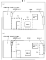
- FIG. 3A is a schematic diagram illustrating an example of setting the attention monitoring area in the daytime.
- FIG. 3B is a schematic diagram illustrating a setting example of the attention monitoring area at night.
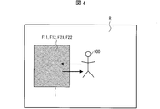
- FIG. 4 is a schematic diagram illustrating the relationship between the operation of the suspicious person 900 and the attention monitoring area.
- the monitoring system 100 records the state in the monitoring area 800 (see FIG. 3 and the like) with the monitoring camera 1 for a certain period of time or for a certain period of time, and stores and analyzes the recorded image R (see FIG. 4) and the like. 900 (monitoring target: see FIG. 4) is detected.
- a store floor where merchandise sales are performed is set as the monitoring area 800.
- the monitoring target of the monitoring system 100 is the suspicious person 900.
- a specific animal may be the monitoring target.
- the monitoring area 800 for example, a store in a mountainous area where food is sold is assumed.
- the monitoring system 100 includes a monitoring camera 1, a wireless LAN 101, a monitoring server 102, and an external storage device 103.
- the monitoring camera 1 transmits information related to each of the recorded recording image R and the attention monitoring area image I (see FIG. 4: details will be described later) to the monitoring server 102 and the external storage device 103 via the wireless LAN 101.
- the monitoring server 102 performs various processes requested by a monitor (not shown) using information related to each of the recorded image R and the focused monitoring area image I. For example, when it is determined that the suspicious person 900 is detected from the information related to the attention monitoring area image I, the monitoring server 102 transmits information related to suspicious person detection to a security company or the like.
- the external storage device 103 stores information relating to each of the recorded image R and the attention monitoring area image I. In addition, the stored information is transmitted to the monitoring camera 1 or the like in response to a call from the monitoring camera 1 or the like.
- NAS Network Attached Storage
- HDR Hard Disk Recorder
- the surveillance camera 1 includes a photographing unit 5, a wireless unit 6, a first power supply unit 7a, a second power supply unit 7b, a first memory 8a, a second memory 8b, and a control unit 9.
- the control unit 9 includes a first image processing device 10a (image processing device) and a second image processing device 10b (image processing device).
- the photographing unit 5 includes a lens, an image sensor, and the like, and records a state in the monitoring area 800 to generate a recorded image R.
- the wireless unit 6 is a wireless LAN circuit, and various information is transmitted and received between the monitoring camera 1 and the monitoring server 102 / external storage device 103 via the wireless unit 6.
- the first power supply unit 7a supplies power to the first image processing apparatus 10a
- the second power supply unit 7b supplies power to the second image processing apparatus 10b
- the first memory 8a is an operation memory for the first image processing apparatus 10a to perform various processes
- the second memory 8b is an operation memory for the second image processing apparatus 10b to perform various processes.
- the first and second memories 8a and 8b store various information handled by the monitoring camera 1.
- the control unit 9 controls each unit of the monitoring camera 1 in an integrated manner.
- the control unit 9 is built in the monitoring camera 1, but the control unit 9 is an external device (not shown) attached to the monitoring camera 1 or a network server used via the wireless unit 6. There may be.
- Both the first and second image processing apparatuses 10a and 10b are constituted by a CPU, for example.
- the first image processing apparatus 10 a includes a setting switching unit 11 and a monitoring target detection unit 12 that performs recording processing of the entire monitoring area 800 and image processing of the recorded image R recorded by the imaging unit 5 of the monitoring camera 1.
- the second image processing device 10 b is a device that mainly performs monitoring image processing (details will be described later), and includes a monitoring image processing execution unit 13.
- the recording process of the entire monitoring area 800 and the image process of the recorded image R by the first image processing apparatus 10a are each performed at a normal resolution. However, when the monitoring camera 1 operates in the low power consumption mode, each of these processes is performed with a low resolution.
- initial monitoring areas are initially set in the first area F11 and the first area F12 in the recorded image R. Is done.
- the first area F11 is a recorded image portion that includes a cash register installation location in the recorded image R
- the first region F12 is a recorded image portion that includes a display location of expensive products in the recorded image R.
- the attention monitoring area is a recorded image portion in the recorded image R that can be arbitrarily set by the monitor as a processing target of monitoring image processing (details will be described later) by the monitoring image processing execution unit 13.
- the attention monitoring area may be initially set to an arbitrary part in the recorded image R, and the size of the attention monitoring area can be changed as appropriate. This initial setting may be performed in advance before the operation of the monitoring camera 1 or may be performed during the operation of the monitoring camera 1.
- the store that is the monitoring area 800 is open during the daytime, and many people enter and exit at the store entrances and entrances for employees, so certain people at these locations are behaving suspiciously. It is difficult to discover. Therefore, it is difficult to detect the suspicious person 900 even if these points are intensively monitored in the daytime.
- the initial setting of the attention monitoring area described above is merely an example, and is not limited to this case.
- the attention monitoring area may be initially set in two recorded image portions other than the first areas F11 and F12 in the recorded image R. Further, for example, the attention monitoring area may be initially set in one recorded image portion in the recorded image R.
- the number and manner of the attention monitoring areas that are initially set may be varied according to the characteristics of the location that becomes the monitoring area 800.
- the setting switching unit 11 shown in FIG. 2 determines whether each of the two switching conditions (first condition) is satisfied. When it is determined that one of the switching conditions is satisfied, the setting switching unit 11 changes the target monitoring area in the recorded image R from the first area F11 / F12 to the second area F21 / F22 different from the first area F11 / F12. (See (b) of FIG. 3). On the other hand, when the setting switching unit 11 determines that the other of the switching conditions is satisfied, the setting switching unit 11 returns the attention monitoring area from the second area F21 / F22 to the first area F11 / F12 (see FIG. 3A).
- the switching condition When the switching condition is satisfied, it is necessary to switch the attention monitoring area in the recorded image R.
- the first specific time when switching from daytime to nighttime is one of the switching conditions. In the present embodiment, 18:30 is set as the first specific time.
- the second specific time that is switched from night to day is the other switching condition. In the present embodiment, 9:30 is set as the second specific time.
- the setting of these specific times may be input by a monitor from an operation input unit (not shown) of the monitoring camera 1 or may be stored in advance in the first memory 8a.
- the second area F21 is a recorded image portion including an employee entrance in the recorded image R
- the second area F22 is a store in the recorded image R.
- This is a recorded image portion including the entrance / exit.
- the setting switching unit 11 calls the information from the first memory 8a.
- the attention monitoring areas set in the first areas F11 and F12 are switched to the second areas F21 and F22.
- the reason why the switching condition is set to such a specific time is that the store in the monitoring area 800 has different numbers of people coming and going and the characteristics of people coming and going depending on the time zone. It is. That is, many people enter and leave the store during the daytime, but since the number of people entering and exiting at night is reduced, it is possible to observe each person entering and leaving the store in more detail. In addition, since the ratio of employees to all people entering and leaving the store at night increases, those who enter the store at night other than employees are relatively suspicious about 900 compared to daytime. The possibility increases.
- the nighttime monitoring area 800 in the nighttime, focus on these locations so that the watched monitoring area includes recorded images near the store entrance and the entrance for employees. If monitored, there is a high possibility that the suspicious person 900 can be detected earlier. Therefore, 18:30, which can be said that the time zone has become nighttime, is set as one of the switching conditions, and when it reaches 18:30, the attention monitoring area is switched to the second area F21 / F22 for nighttime, and the suspicious person 900 Can be detected earlier. Note that the above-described switching of the attention monitoring area to the second areas F21 and F22 is merely an example, and is not limited to this case.
- the monitoring target detection unit 12 illustrated in FIG. 2 determines whether or not there is a suspicious person 900 in the attention monitoring area that is initially set in the first areas F11 and F12 before the setting switching section 11 switches the attention monitoring area. Is detected (see FIG. 3A). Further, the monitoring target detection unit 12 detects whether or not there is a suspicious person 900 in the attention monitoring area switched to the second area F21 / F22 after the setting monitoring part 11 switches the attention monitoring area. (See FIG. 3B).
- the suspicious person 900 (specifically, at least a part of the body of the suspicious person 900) is monitored. This refers to the case where the monitoring target detection unit 12 recognizes that the image is displayed in the area (the first area F11 / F12 or the second area F21 / F22) (see the arrow on the upper side in the drawing).
- the case where the monitoring target detection unit 12 no longer detects the presence of the suspicious person 900 indicates a case where the monitoring target detection unit 12 recognizes that the suspicious person 900 is no longer displayed in the attention monitoring area (in the drawing). (See the arrow at the bottom of the page.)
- the monitoring operation of the attention monitoring area switched to the second area F21 / F22 by the monitoring target detection section 12 is performed from the setting switching section 11 from the first area F11 / F12 to the second area F21 / F22. It is started by receiving information indicating that the switch has been made.
- the monitoring image processing execution unit 13 executes monitoring image processing for monitoring the suspicious person 900 for the attention monitoring area image I when the monitoring target detection unit 12 detects the presence of the suspicious person 900 in the attention monitoring area. To do.
- the execution of the monitoring image processing by the monitoring image processing execution unit 13 is started by receiving information indicating that the presence of the suspicious person 900 is detected from the monitoring target detection unit 12.
- the attention monitoring area image I refers to a recorded image of an area where the presence of the suspicious person 900 is detected in the attention monitoring area (see FIG. 4). Further, as an example of the monitoring image processing, there is a process of cutting out only an area in which the presence of the suspicious person 900 is detected in the attention monitoring area, recording at a high resolution, and generating a high resolution attention monitoring area image I. be able to. Further, for example, a process of performing image analysis of the attention monitoring area image I and recognizing a face projected in the image I can be mentioned.
- the monitoring image processing execution unit 13 calls a suspicious person database stored in the monitoring server 102 or an external information processing apparatus, and the image of the suspicious person database and the attention monitoring area image I The process which collates with the face projected on.
- a process for determining that the person projected in the image I is the suspicious person 900 is given as an example. Can do.
- the attention monitoring area is recorded at a low resolution, and after the monitoring target detection unit 12 detects the presence of the suspicious person 900 in the attention monitoring area, As an example, a process in which an area where the presence of the suspicious person 900 is detected is recorded with an increased resolution and the attention monitoring area image I is generated can be given as an example.
- the monitoring image processing execution unit 13 continues or stops the execution of the monitoring image processing according to the detection result relating to the presence or absence of the suspicious person 900 by the monitoring target detection unit 12. Specifically, the monitoring image processing execution unit 13 starts executing the monitoring image processing when the monitoring target detection unit 12 detects the presence of the suspicious person 900 in the attention monitoring area, and detects the presence of the suspicious person 900. The monitoring image processing is continued while the image is being processed. On the other hand, when the monitoring target detection unit 12 no longer detects the presence of the suspicious person 900, the monitoring image processing execution unit 13 stops the execution of the monitoring image processing.
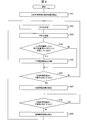
- FIG. 5 is a flowchart showing an example of the image processing method.
- step S101 the monitoring image processing execution unit 13 starts recording processing of the attention monitoring area that is initially set in the first areas F11 and F12 in the recorded image R, and S102. Proceed to
- the setting switching unit 11 confirms the time in S102, and determines in S103 whether the confirmed time satisfies one of the switching conditions (has reached 18:30).
- NO hereinafter abbreviated as “N”
- the monitoring target detection unit 12 determines whether or not there is a suspicious person 900 in the attention monitoring area that is initially set in the first areas F11 and F12. Is detected (S105: monitoring target detection step).
- the setting switching unit 11 changes the attention monitoring area in the recorded image R from the first area F11 / F12 to the second area F21 in S104. Switch to F22 and proceed to S105.
- the monitoring target detection unit 12 detects whether or not there is a suspicious person 900 in the attention monitoring area switched to the second areas F21 and F22.
- the monitoring image processing execution unit 13 starts executing the monitoring image processing on the attention monitoring area image I in the attention monitoring area where the presence of the suspicious person 900 is detected, and the process proceeds to S107. Proceed (S106: monitoring image processing execution step). On the other hand, if it is determined as N in S105, the monitoring image processing execution unit 13 continues the recording process of the attention monitoring area switched to the second areas F21 and F22. Further, the setting switching unit 11 executes the process of S102 again.
- the monitoring target detection unit 12 detects again whether or not there is a suspicious person 900 in the attention monitoring area (monitoring target detection step).
- the monitoring image processing by the monitoring image processing execution unit 13 continues and the monitoring target detection unit 12 executes the processing of S107 again.
- the monitoring image processing execution unit 13 stops the execution of the monitoring image processing in S108, and returns to S102.
- the setting switching unit 11 confirms the time in S102, and determines whether or not the confirmed time satisfies the other switching condition (9:30) in S103.
- the monitoring target detection unit 12 detects whether or not there is a suspicious person 900 in the attention monitoring area that has been switched to the second areas F21 and F22 in S105.
- the setting switching unit 11 returns the attention monitoring area in the recorded image R from the second area F21 / F22 to the first area F11 / F12 in S104, and proceeds to S105.
- the monitoring target detection unit 12 detects whether or not there is a suspicious person 900 in the attention monitoring area set again in the first areas F11 and F12.
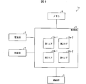
- FIG. 6 is a block diagram illustrating a functional configuration of a modified example of the monitoring camera 1.
- the image processing apparatus includes four CPUs, ie, a first core 10a-1, a second core 10a-2, a third core 10b-1, and a fourth core 10b-2. It may be comprised.
- the surveillance camera may incorporate an image processing device including the four CPUs, like the surveillance camera 1a.
- the monitoring camera 1a includes a power supply unit 7 instead of the first and second power supply units 7a and 7b, and a memory 8 instead of the first and second memories 8a and 8b.
- the first core 10a-1 and the second core 10a-2 perform the same processing as the first image processing apparatus 10a. Further, the third core 10b-1 and the fourth core 10b-2 perform the same processing as that of the second image processing apparatus 10b.
- the division of processing roles between the first core 10a-1 and the second core 10a-2 and the division of processing roles between the third core 10b-1 and the fourth core 10b-2 are arbitrarily set. Also good. Further, the number of cores constituted by the CPU may be arbitrarily changed.
- the first image processing device 10a including the setting switching unit 11 and the monitoring target detection unit 12 and the second image processing device 10b including the monitoring image processing execution unit 13 are separated.
- the setting switching unit 11, the monitoring target detection unit 12, and the monitoring image processing execution unit 13 may be provided in one image processing apparatus.
- the first and second image processing apparatuses 10a and 10b are built in the monitoring camera 1, but the present invention is not limited to this case.
- the first and second image processing apparatuses 10a and 10b may be built in the monitoring server 102, or may be built in an information processing apparatus separate from the monitoring server 102 and the external storage device 103. Also good.
- the first and second image processing apparatuses 10a and 10b may each be a single unit.
- the first and second image processing apparatuses 10a and 10b and the monitoring camera are wirelessly connected via the wireless LAN 101 or the like.
- the monitoring system according to one embodiment of the present invention only needs to include at least an image processing apparatus and a monitoring camera connected (wired / wireless) to the image processing apparatus.
- FIG. 1 is a block diagram illustrating an example of a functional configuration of the monitoring system 200.
- FIG. 2 is a block diagram illustrating an example of a functional configuration of the monitoring camera 2.
- FIG. 7 is a schematic diagram illustrating an example of setting the attention monitoring area in the daytime.
- a monitoring system 200 shown in FIG. 1 includes a monitoring camera 2 instead of the monitoring camera 1.
- Other configurations and functions of the monitoring system 200 are the same as those of the monitoring system 100.
- the surveillance camera 2 shown in FIG. 2 includes a first image processing device 20a instead of the first image processing device 10a.
- Other configurations and functions of the monitoring camera 2 are the same as those of the monitoring camera 1.
- the setting switching unit 11 determines that one of the first determination criteria (one of a plurality of determination criteria) is satisfied, the first image processing device 20a illustrated in FIG. The region is switched from the first region F11 / F12 to the second region F21 / F22.
- the setting switching unit 11 of the first image processing device 20a determines that one of the second determination criteria (one of a plurality of determination criteria) is satisfied, the attention monitoring area in the recorded image R is set to the first monitoring region. The area is switched from the first area F11 to the second areas F21 and F22. The operation when it is determined that the other of the first and second setting switching conditions is satisfied is the same as that of the setting switching unit 11 of the first image processing apparatus 10a.
- the focus monitoring area in the recorded image R needs to be switched.
- the first specific time when switching from daytime to nighttime in summer is one of the first determination criteria. In the present embodiment, 19:00 is set as the first specific time.
- the second specific time that switches from night to day is the other of the first determination criteria. In the present embodiment, 9:00 is set as the second specific time.
- the third specific time when switching from daytime to nighttime in a season other than summer is one of the second determination criteria.
- 18:00 is set as the third specific time.
- the fourth specific time that switches from night to day in the season other than summer is the other of the second determination criteria.
- 10:00 is set as the fourth specific time.
- Whether the season is summer or whether the season is other than summer is determined by date.
- the date ranges from June 1 to September 30 as the summer season, and the period from October 1 to May 31 as the season other than the summer season.
- the attention monitoring area is initially set in the first area F11 and the first area F13 in the recorded image R.
- the first area F11 is a recorded image portion including the location where the cash register is set in the recorded image R
- the first area F13 is a seasonal product (a product that sells well in summer) in the recorded image R. This is a recorded image portion including the display part.
- the attention monitoring area is initially set in the first area F11 in the recorded image R.
- a recorded image portion that includes a display location of a seasonal product (a product that sells well in summer) in the recorded image R is displayed. Exclude from the first region.
- a recorded image portion including a display location of other products in the recorded image R may be set as the first area.
- a recorded image portion including a display location of seasonal products (products that are often sold in winter) in the recorded image R may be set as the first region.
- the second area F21 is a recorded image portion including an employee entrance / exit in the recorded image R
- the second area F22 includes a store entrance / exit in the recorded image R. This is a recorded image portion (see FIG. 3B).
- FIG. 8 is a flowchart showing an example of the image processing method.
- the monitoring image processing execution unit 13 is initially set in the first area F11 / F13 in the recorded image R (when the season is summer) or the first area F11 in the recorded image R (when the season is other than summer). Recording processing of the set attention monitoring area is started, and the process proceeds to S202.
- the setting switching unit 11 confirms the date in S202, confirms the time in S203, and proceeds to S204.
- the setting switching unit 11 satisfies one of the first determination criteria or one of the second determination criteria based on the confirmed date / time (whether it is 19:00 in summer, Alternatively, it is determined whether or not it is 18:00 in a season other than summer).
- the monitoring target detection unit 12 detects whether or not there is a suspicious person 900 in the first area F11 / F13 or the attention monitoring area initially set in the first area F11 ( S206: Monitoring target detection step).
- the setting switching unit 11 changes the attention monitoring area in the recorded image R from the first areas F11 and F13 in S205. The area is switched to the two areas F21 and F22, and the process proceeds to S206.
- the setting switching unit 11 changes the attention monitoring area in the recorded image R from the first area F11 to the second area in S205. Switch to F21 / F22 and proceed to S206.
- the monitoring object detection unit 12 detects whether or not there is a suspicious person 900 in the attention monitoring area switched to the second area F21 / F22 (S206: monitoring object detection step).
- the setting switching unit 11 confirms the date in S202, confirms the time in S203, and proceeds to S204.
- the setting switching unit 11 satisfies either the other of the first determination criteria or the other of the second determination criteria based on the confirmed date and time (whether it is 9:00 in the summer, Alternatively, it is determined whether or not it is 10:00 in a season other than summer). If it is determined as N in S204, the monitoring target detection unit 12 detects whether or not there is a suspicious person 900 in the attention monitoring area switched to the second area F21 / F22 in S206.
- the setting switching unit 11 changes the attention monitoring area in the recorded image R from the second areas F21 and F22 to the first in S205. It returns to 1 area
- the setting switching unit 11 changes the attention monitoring area in the recorded image R from the second areas F21 and F22 in S205. Returning to the one area F11, the process proceeds to S206.
- the monitoring target detection unit 12 detects whether or not there is a suspicious person 900 in the attention monitoring area set again in the first area F11 / F13 or the first area F11.
- the processes of S207 to S209 are the same as described above, and the processes of S202 to S209 are continuously executed until the monitoring of the monitoring area 800 by the monitoring system 200 is completed.
- FIG. 1 is a block diagram illustrating an example of a functional configuration of the monitoring system 300.
- FIG. 2 is a block diagram illustrating an example of a functional configuration of the monitoring camera 3.
- the surveillance camera 3 shown in FIG. 2 includes a first image processing device 30a instead of the first image processing devices 10a and 20a. Other configurations and functions of the monitoring camera 3 are the same as those of the monitoring cameras 1 and 2.
- the setting switching unit 11 determines whether or not the switching determination stop condition (second condition) is satisfied.
- the setting switching unit 11 of the first image processing apparatus 30a sets the attention monitoring areas initially set in the first areas F11 and F12 as the second areas F21 and F22 (third areas). ) (See FIG. 3).
- the operation when it is determined that the switching determination stop condition is not satisfied is the same as that of the setting switching unit 11 of the first image processing apparatuses 10a and 20a.
- the setting switching unit 11 of the first image processing apparatus 30a stops the switching condition satisfaction determination.
- the switching determination stop condition is that it is not a store working day.
- a holiday and a regular holiday are set as a case where the store is not a working day. Whether or not it is an operating day of the store is determined by the date and day of the week.
- the condition for canceling the switching judgment is that the store is not in operation, because if the store is not in operation, there is no customer access throughout the day, and the situation of the store approximates that of the night on the operation day. This is because the attention monitoring area is fixed to the second areas F21 and F22 in accordance with the actual situation of the store.
- the above-described fixation of the attention monitoring area to the second areas F21 and F22 is merely an example, and is not limited to this case.
- the attention monitoring area that is initially set in the first areas F11 and F12 may be fixed to the first areas F11 and F12 as they are.
- the attention monitoring area may be fixed to a specific area (third area) different from the first areas F11 and F12 and the second areas F21 and F22.
- the monitoring target detection unit 12 detects whether or not there is a suspicious person 900 in the attention monitoring area fixed to the second areas F21 and F22.
- FIG. 9 is a flowchart illustrating an example of the image processing method.
- the monitoring image processing execution unit 13 starts recording processing of the attention monitoring area that is initially set in the first areas F11 and F12 in the recording image R, and proceeds to S302.
- the setting switching unit 11 confirms the date in S302, confirms the day of the week in S303, and proceeds to S304.
- the setting switching unit 11 determines whether the switching determination stop condition is satisfied (whether it is a working day of the store). If it is determined that the answer is N in S304, the setting switching unit 11 checks the time in S305 and proceeds to S306.
- the setting switching unit 11 determines whether the confirmed time satisfies one of the switching conditions (has reached 18:30).
- the monitoring target detection unit 12 detects whether or not there is a suspicious person 900 in the attention monitoring area that is initially set in the first areas F11 and F12 (S309: monitoring target detection step). ).
- the setting switching unit 11 switches the attention monitoring area in the recorded image R from the first area F11 / F12 to the second area F21 / F22 in S307, and proceeds to S309.
- the monitoring target detection unit 12 detects whether or not there is a suspicious person 900 in the attention monitoring area switched to the second area F21 / F22.
- the setting switching unit 11 fixes the attention monitoring area to the second areas F21 and F22 in S308, and proceeds to S309.
- the monitoring target detection unit 12 detects whether or not there is a suspicious person 900 in the attention monitoring area fixed to the second areas F21 and F22.
- the process After executing the process of S312, the process returns to S302. Since each process of S302 to S305 and S308 is as described above, a description thereof will be omitted.
- the setting switching unit 11 determines whether or not the confirmed time satisfies the other switching condition (has reached 9:30). If it is determined as N in S306, the monitoring target detection unit 12 detects whether or not there is a suspicious person 900 in the attention monitoring area that has been switched to the second areas F21 and F22 in S309.
- the setting switching unit 11 returns the attention monitoring area in the recorded image R from the second area F21 / F22 to the first area F11 / F12 in S307, and proceeds to S309.
- the monitoring target detection unit 12 detects whether or not there is a suspicious person 900 in the attention monitoring area set again in the first areas F11 and F12.
- the processes of S310 to S312 are the same as described above, and the processes of S302 to S312 are continuously executed until the monitoring of the monitoring area 800 by the monitoring system 300 is completed.
- FIG. 1 is a block diagram illustrating an example of a functional configuration of the monitoring system 400.
- FIG. 2 is a block diagram illustrating an example of a functional configuration of the monitoring camera 4.
- the surveillance camera 4 shown in FIG. 2 includes a first image processing device 40a instead of the first image processing devices 10a, 20a, and 30a.
- Other configurations and functions of the monitoring camera 4 are the same as those of the monitoring cameras 1, 2, and 3.
- the first image processing apparatus 40a illustrated in FIG. 2 determines whether the setting cancellation condition (third condition) is satisfied after the setting switching unit 11 switches the attention monitoring area from the first area to the second area. When it is determined that the setting cancellation condition is satisfied, the setting of the attention monitoring area is canceled. The operation when it is determined that the setting cancellation condition is not satisfied is the same as that of the setting switching unit 11 of the first image processing apparatus 10a / 20a / 30a.
- the setting cancellation condition is a condition for canceling the setting of the attention monitoring area switched to the second area in the recorded image.
- various setting cancellation conditions can be set.
- various regions (recorded image portions) in the recorded image can be set as the second region in accordance with the type of place serving as the monitoring area.
- the monitoring area is a store displaying rain gear supplies
- the switching condition is that the rain has started
- the setting cancellation condition is that the rain has stopped
- the monitoring area is a store displaying a new product
- the recorded image portion including the display location of the new product in the recorded image is set as the second area.
- the switching condition is immediately after a new product arrives, and the setting cancellation condition is that the new product is sold out.
- the monitoring area is a ticket gate of a station
- the switching condition is that the user has purchased a ticket at the automatic ticket vending machine
- the setting cancellation condition is that the user has passed the automatic ticket gate.
- the monitoring area is a platform of a station
- the monitoring area is a parking lot
- the recorded image portion including the entrance of the parking lot in the recorded image is the second area.
- the switching condition is that the user has taken the parking ticket
- the setting cancellation condition is that the user's car has left the parking lot entrance.
- the switching condition is that the user has completed payment with the parking fee adjustment machine
- the setting cancellation condition is that the user's car has left the parking lot exit.
- the event that is the content of the switching condition and the event that is the content of the setting cancellation condition are collectively referred to as a “switching element”.
- the setting switching unit 11 receives the information related to the “switching element” from an external communication device or the like via the wireless LAN 101.
- FIG. 10 is a flowchart illustrating an example of the image processing method.
- the monitoring image processing execution unit 13 starts recording processing of the attention monitoring area that is initially set in the first area in the recorded image, and the process proceeds to S402.
- the setting switching unit 11 confirms the switching element, and the process proceeds to S403.
- the setting switching unit 11 determines whether the switching condition is satisfied based on the confirmed switching element.
- the monitoring target detection unit 12 detects whether or not there is a suspicious person 900 in the attention monitoring area that is initially set in the first area (S405: monitoring target detection step).
- the setting switching unit 11 switches the attention monitoring area in the recorded image from the first area to the second area in S404, and proceeds to S405.
- the monitoring target detection unit 12 detects whether or not there is a suspicious person 900 in the attention monitoring area switched to the second area.
- the setting switching unit 11 confirms the switching element in S402, and determines whether or not the setting cancellation condition is satisfied based on the confirmed switching element in S403. If it is determined as N in S403, the monitoring target detection unit 12 detects whether or not there is a suspicious person 900 in the attention monitoring area that has been switched to the second area in S405.
- the first power supply unit 7a and the second power supply unit 7b, and the first memory 8a and the second memory 8b are installed separately. However, they may be configured to be used as one power supply unit 7 or one memory 8 as shown in FIG.
- control blocks (particularly the monitoring target detection unit 12 and the monitoring image processing execution unit 13) of the first image processing devices 10a to 40a and the second image processing device 10b are logic circuits (IC chips) or the like formed in an integrated circuit (IC chip) or the like. Hardware) or software using a CPU (Central Processing Unit).
- the first image processing apparatuses 10a to 40a and the second image processing apparatus 10b are a CPU that executes instructions of a program that is software that realizes each function, and the program and various data are computers (or CPUs).
- a ROM (Read Only Memory) or a storage device (referred to as “recording medium”) recorded in a readable manner, a RAM (Random Access Memory) for developing the program, and the like are provided.
- the objective of this invention is achieved when a computer (or CPU) reads the said program from the said recording medium and runs it.
- a “non-temporary tangible medium” such as a tape, a disk, a card, a semiconductor memory, a programmable logic circuit, or the like can be used.
- the program may be supplied to the computer via an arbitrary transmission medium (such as a communication network or a broadcast wave) that can transmit the program.
- an arbitrary transmission medium such as a communication network or a broadcast wave
- one embodiment of the present invention can also be realized in the form of a data signal embedded in a carrier wave, in which the program is embodied by electronic transmission.
- the image processing apparatuses (first image processing apparatuses 10a, 20a, 30a, and 40a, second image processing apparatus 10b) according to the first aspect of the present invention are recorded images recorded by the monitoring cameras (1, 2, 3, 4).
- (R) is an image processing apparatus, and whether or not there is a monitoring target (suspicious person 900) in the attention monitoring area set in the first area (F11, F12, F13) in the recorded image.
- a monitoring image processing execution unit (13) for performing monitoring image processing for monitoring the monitoring target with respect to an image in the attention monitoring region (attention monitoring region image I).
- the monitoring image processing execution unit executes the monitoring image processing.
- the monitoring target detection unit detects whether or not there is a monitoring target in the target monitoring area set in the recorded image recorded by the monitoring camera.
- the monitoring image processing execution unit executes monitoring image processing when the monitoring target detection unit detects the presence of the monitoring target.
- the image processing apparatus is switched to the high power consumption mode only while the monitoring target exists in the target monitoring area, and the image in the area is displayed.
- Monitoring image processing can be continued with high resolution. Moreover, this process can be performed by one monitoring camera.
- the operation of the monitoring target in the entire monitoring area can be recorded and processed, it is possible to grasp where the monitoring target has entered and where it has escaped. Therefore, it is possible to improve the monitoring accuracy while suppressing the calculation cost and reducing the cost.
- the image processing apparatus is the image processing apparatus according to aspect 1, in which the monitoring image processing execution unit detects the presence of the monitoring object after the monitoring image processing execution unit starts executing the monitoring image processing. When there is no more, the execution of the monitoring image processing may be stopped.
- the monitoring image processing execution unit stops execution of the monitoring image processing when the monitoring target detection unit no longer detects the presence of the monitoring target after the start of execution of the monitoring image processing. Therefore, for example, when there is no longer a monitoring target, the image processing apparatus can be switched to the low power consumption mode to perform recording / image processing of the entire monitoring area with low resolution. Therefore, it is possible to further reduce the calculation cost and reduce the cost while improving the monitoring accuracy.
- the image processing apparatus determines whether or not the first condition that requires switching of the attention monitoring area in the recorded image is satisfied in the aspect 1 or 2, and the first A setting switching unit that switches the attention monitoring area in the recorded image from the first area to the second area (F21, F22) different from the first area (F11, F12) when it is determined that the condition is satisfied.
- (11) may be further provided, and the monitoring target detection unit may detect whether or not the monitoring target exists in the target monitoring area set in the second area.
- the image processing apparatus further includes a setting switching unit that switches the attention monitoring region from the first region to the second region when it is determined that the first condition is satisfied. ing.
- the monitoring target detection unit detects whether or not a monitoring target exists in the attention monitoring area set in the second area.
- the attention monitoring area set before the situation change is changed to another area (second area) in the recorded image. ) Can be re-applied to respond appropriately to this situation change. Therefore, it is possible to further improve the monitoring accuracy while suppressing calculation costs and reducing costs.
- the first condition includes a plurality of determination criteria
- the setting switching unit includes a plurality of the determination criteria.
- the setting switching unit switches the attention monitoring region from the first region to the second region when it is determined that any one of the plurality of determination criteria is satisfied.
- the setting switching unit satisfies a second condition for canceling the satisfaction determination of the first condition. If it is determined whether or not the second condition is satisfied, the attention monitoring area is fixed to either the first area or a third area (F21, F22) different from the first area, The monitoring target detection unit may detect whether or not the monitoring target exists in the attention monitoring area fixed to either the first area or the third area.
- the setting monitoring unit fixes the attention monitoring region to either the first region or the third region. Further, the monitoring target detection unit detects whether or not a monitoring target exists in the target monitoring region fixed to either the first region or the third region by the setting switching unit.
- the monitoring target area is changed to a specific area ( The first region or the third region can be fixed. Therefore, wasteful switching of the monitoring target area can be prevented, and the calculation cost can be further suppressed and the cost can be reduced while improving the monitoring accuracy.
- the setting switching unit may be configured such that the setting region is the first region to the second region of the attention monitoring region. After switching to, it is determined whether or not the third condition for canceling the setting of the attention monitoring area in the recorded image is satisfied, and when it is determined that the third condition is satisfied, the attention monitoring You may cancel the setting of the area.
- the setting switching unit cancels the setting of the attention monitoring area switched to the second area when it is determined that the third condition is satisfied. Accordingly, by appropriately setting the content of the third condition, after the attention monitoring area is switched to the second area, the setting of the second area is continued while the attention monitoring area needs to be monitored. If you do not need to monitor the area, you can cancel the setting. Therefore, it is possible to prevent unnecessary monitoring of the monitoring target area, and it is possible to further reduce calculation cost and reduce costs while improving monitoring accuracy.
- the surveillance camera (1, 2, 3, 4) according to aspect 7 of the present invention is an image processing apparatus according to any one of aspects 1 to 6 (first image processing apparatuses 10a, 20a, 30a, 40a, second image).
- a processing device 10b) is provided. According to the above configuration, it is possible to realize a monitoring camera capable of improving the monitoring accuracy while suppressing calculation costs and reducing costs.
- a monitoring system (100, 200, 300, 400) according to aspect 8 of the present invention includes a monitoring camera connected to the image processing apparatus according to any one of aspects 1 to 6. According to the above configuration, it is possible to realize a monitoring system capable of improving the monitoring accuracy while suppressing calculation costs and reducing costs.
- An image processing method is an image processing method for processing a recorded image recorded by a surveillance camera, and the attention set in the first region (F11, F12, F13) in the recorded image.
- a monitoring object detection step (S105, S107, S206, S208, S309, S311, S405, S407) for detecting whether or not a monitoring object exists in the monitoring area, and the image in the attention monitoring area
- a monitoring image processing execution step (S106, S207, S310, S406) for performing monitoring image processing for monitoring the target, and when the presence of the monitoring target is detected in the monitoring target detection step, In the monitoring image processing execution step, the monitoring image processing is executed.
- the image processing apparatus may be realized by a computer.
- the image processing apparatus is operated on each computer by causing the computer to operate as each unit (software element) included in the image processing apparatus.
- the program of the image processing apparatus to be realized in this way and a computer-readable recording medium on which the program is recorded also fall within the scope of the present invention.
Landscapes
- Physics & Mathematics (AREA)
- General Physics & Mathematics (AREA)
- Business, Economics & Management (AREA)
- Emergency Management (AREA)
- Engineering & Computer Science (AREA)
- Multimedia (AREA)
- Signal Processing (AREA)
- Closed-Circuit Television Systems (AREA)
- Alarm Systems (AREA)
- Studio Devices (AREA)
Abstract
簡易な構成で計算コストの抑制・費用削減を図りつつ、監視精度を向上させる。注目監視領域内に監視対象(900)が存在するか否かを検知する監視対象検知部(12)と、注目監視領域内の画像(I)について監視画像処理を行う監視画像処理実行部(13)と、を備え、監視対象検知部(12)が監視対象(900)の存在を検知した場合に、監視画像処理実行部(13)は、監視画像処理を実行する。
Description
本発明は、画像処理装置、監視カメラ、監視システム、プログラムおよび画像処理方法に関する。
近年、不審者検知などの防犯・治安維持を目的とする監視カメラ、監視システム等について、計算コストを抑制しつつ監視精度を向上させるための研究開発が活発に行われている。例えば、特許文献1には、監視カメラと動線分析装置とを有する監視システム等が開示されている。動線分析装置は、監視対象の動線を計測する動線計測手段と、可視領域を計測する可視領域計測手段と、動線と可視領域との時間的・空間的な重なりを検出する重なり検出手段と、時間的・空間的な重なりを有する区間の動線を抽出する動線抽出手段と、を有する。
しかしながら、特許文献1に開示された監視システムは、監視カメラを設置するだけでなく監視者が装着型カメラを装着しなければならず、少なくとも2台のカメラが必要となる。それゆえ、1台の監視カメラで監視するよりも監視システムの構成が複雑になり、かつ高コストとなってしまう。また、特許文献1に開示された動線分析装置は、装着型カメラを装着している監視者の可視領域の外、すなわち装着型カメラの撮影可能範囲の外に存在する不審者等については、その動線分析を行うことができない。それゆえ、特に不審者等が監視者の可視領域の外に存在する場合の監視精度が低下してしまう。
本発明の一態様は、上記の各問題点に鑑みてなされたものであり、その目的は、簡易な構成で計算コストの抑制・費用削減を図りつつ、監視精度を向上させることにある。
上記の課題を解決するために、本発明の一態様に係る画像処理装置は、監視カメラによって録画された録画画像を処理する画像処理装置であって、前記録画画像内の第1領域に設定された注目監視領域内に、監視対象が存在するか否かを検知する監視対象検知部と、前記注目監視領域内の画像について、前記監視対象を監視するための監視画像処理を行う監視画像処理実行部と、を備え、前記監視対象検知部が前記監視対象の存在を検知した場合に、前記監視画像処理実行部は、前記監視画像処理を実行する。
また、上記の課題を解決するために、本発明の一態様に係る画像処理方法は、監視カメラによって録画された録画画像を処理する画像処理方法であって、前記録画画像内の第1領域に設定された注目監視領域内に、監視対象が存在するか否かを検知する監視対象検知ステップと、前記注目監視領域内の画像について、前記監視対象を監視するための監視画像処理を行う監視画像処理実行ステップと、を含み、前記監視対象検知ステップにて前記監視対象の存在が検知された場合に、前記監視画像処理実行ステップでは、前記監視画像処理を実行する。
本発明の一態様によれば、監視画像処理が行われる録画画像内の領域を注目監視領域に限定することで、簡易な構成で計算コストの抑制・費用削減を図りつつ、監視精度を向上させることができる。
〔実施形態1〕
以下、本発明の実施の形態について、図1~図6を参照しながら詳細に説明する。なお、本実施形態以下の各実施形態においては、本発明の一態様に係る画像処理装置が監視カメラに内蔵されている場合を例に挙げて説明する。
以下、本発明の実施の形態について、図1~図6を参照しながら詳細に説明する。なお、本実施形態以下の各実施形態においては、本発明の一態様に係る画像処理装置が監視カメラに内蔵されている場合を例に挙げて説明する。
但し、本発明の一態様に係る画像処理装置は、監視カメラに内蔵されている必要は必ずしもない。例えば、本発明の一態様に係る画像処理装置が外部の情報処理装置に内蔵され、監視カメラによって録画された録画画像に係る情報を情報処理装置と監視カメラとの間で送受信することにより、監視画像処理を行ってもよい。
<監視システムおよび監視カメラの機能的構成>
まず、図1~図4を参照して、監視システム100および監視カメラ1の機能的構成について説明する。図1は、監視システム100の機能的構成の一例を示すブロック図である。図2は、監視カメラ1の機能的構成の一例を示すブロック図である。図3の(a)は、昼間における注目監視領域の設定例を示す概略図である。図3の(b)は、夜間における注目監視領域の設定例を示す概略図である。図4は、不審者900の動作と注目監視領域との関係を示す概略図である。
まず、図1~図4を参照して、監視システム100および監視カメラ1の機能的構成について説明する。図1は、監視システム100の機能的構成の一例を示すブロック図である。図2は、監視カメラ1の機能的構成の一例を示すブロック図である。図3の(a)は、昼間における注目監視領域の設定例を示す概略図である。図3の(b)は、夜間における注目監視領域の設定例を示す概略図である。図4は、不審者900の動作と注目監視領域との関係を示す概略図である。
監視システム100は、監視カメラ1によって監視エリア800(図3等参照)内の様子を一定時間、あるいは一定期間録画し、録画画像R(図4参照)の保存・画像解析等を行って不審者900(監視対象:図4参照)を検知する。本実施形態以下の各実施形態(実施形態4以外)では、監視エリア800として商品販売が行われている店舗のフロアが設定されているものとする。
なお、監視システム100の導入が可能な監視エリア800としては、上述のような店舗のフロアの他にも、様々な建物・施設内のスペースが対象となる。また、本実施形態以下の各実施形態では監視システム100の監視対象を不審者900としているが、例えば特定の動物を監視対象としてもよい。この場合、監視エリア800としては、例えば食物を販売する山間部の商店などが想定される。
監視システム100は、図1に示すように、監視カメラ1、無線LAN101、監視サーバ102および外部記憶装置103を備えている。監視カメラ1は、録画した録画画像Rおよび注目監視領域画像I(図4参照:詳細は後述)のそれぞれに係る情報を、無線LAN101を介して監視サーバ102および外部記憶装置103に送信する。また、監視サーバ102は、録画画像Rおよび注目監視領域画像Iのそれぞれに係る情報を用いて、監視者(不図示)の要求する各種処理を行う。例えば、監視サーバ102は、注目監視領域画像Iに係る情報から不審者900が検知されたことが判明した場合、警備会社等に不審者検知に係る情報を送信する。外部記憶装置103は、録画画像Rおよび注目監視領域画像Iのそれぞれに係る情報を記憶する。また、監視カメラ1等からの呼び出しに応じて記憶している情報を監視カメラ1等に送信する。外部記憶装置103としては、例えばNAS(Network Attached Storage;ネットワーク接続ストレージ)、HDR(HardDisk Recorder;ハードディスクレコーダ)などが想定される。
図2に示すように、監視カメラ1は、撮影部5、無線部6、第1電源部7a、第2電源部7b、第1メモリ8a、第2メモリ8bおよび制御部9を備えている。また、制御部9は、第1画像処理装置10a(画像処理装置)および第2画像処理装置10b(画像処理装置)を備えている。撮影部5は、レンズや撮像素子等で構成されており、監視エリア800内の様子を録画して録画画像Rを生成する。無線部6は無線LAN回路であり、無線部6を介して、監視カメラ1と監視サーバ102・外部記憶装置103との間で各種情報の送受信が行なわれる。
第1電源部7aは第1画像処理装置10aに電力を供給し、第2電源部7bは第2画像処理装置10bに電力を供給する。第1メモリ8aは、第1画像処理装置10aが各種処理を行うための動作メモリであり、第2メモリ8bは、第2画像処理装置10bが各種処理を行うための動作メモリである。また、第1・第2メモリ8a・8bともに、監視カメラ1にて扱われる各種情報を記憶する。
制御部9は、監視カメラ1の各部を統括して制御する。なお、図2では制御部9は監視カメラ1に内蔵されているが、制御部9は監視カメラ1に外付けされた外部装置(不図示)や、無線部6を介して利用するネットワークサーバであってもよい。
第1・第2画像処理装置10a・10bともに、例えばCPUで構成されている。第1画像処理装置10aは、監視エリア800全体の録画処理や、監視カメラ1の撮影部5によって録画された録画画像Rの画像処理を行い、設定切替部11および監視対象検知部12を備えている。第2画像処理装置10bは、主として監視画像処理(詳細は後述)を行う装置であり、監視画像処理実行部13を備えている。
第1画像処理装置10aによる監視エリア800全体の録画処理、および録画画像Rの画像処理は、それぞれ通常解像度で行われる。但し、監視カメラ1が低消費電力モードで作動する場合には、これらの各処理は低解像度で行われる。
ここで、本実施形態では、図3の(a)に示すように、監視エリア800を昼間に監視する場合、録画画像R内における第1領域F11および第1領域F12に注目監視領域が初期設定される。第1領域F11は、録画画像R内のレジの設置箇所が含まれる録画画像部分であり、第1領域F12は、録画画像R内の高額商品の陳列箇所が含まれる録画画像部分である。
また、注目監視領域は、監視画像処理実行部13による監視画像処理(詳細は後述)の処理対象として監視者が任意に初期設定できる、録画画像R内の録画画像部分である。具体的には、注目監視領域は録画画像R内の任意の部分に初期設定してよいし、注目監視領域の大きさも適宜変更することができる。この初期設定は、監視カメラ1の作動前に予め行っておいてもよいし、監視カメラ1の作動中に行ってもよい。
監視エリア800である店舗は、昼間は営業時間内であり、店の出入口や従業員用の出入口では多くの人が出入りすることから、これらの箇所での特定の人物が不審な挙動をしていたとしても発見が困難である。それゆえ、昼間にこれらの箇所を重点的に監視しても、不審者900を検知することは困難である。
一方、現金が存在するレジの周辺や、店舗の被害がより深刻になる高額商品の陳列箇所付近については、昼間であっても高額商品の持ち去りや現金・高額商品の強奪等が発生する危険性がある。また、持ち去り等が発生した場合に、現場およびその周辺にいる従業員の安全を確保する必要がある。そこで、監視エリア800を昼間に監視する場合は、録画画像R内における第1領域F11・F12のそれぞれに、注目監視領域を初期設定する。
なお、上述の注目監視領域の初期設定はあくまで一例であり、この場合に限定されるものではない。例えば、録画画像R内における第1領域F11・F12以外の2つの録画画像部分に注目監視領域を初期設定してもよい。また例えば、録画画像R内の1つの録画画像部分に注目監視領域を初期設定してもよい。さらには、監視エリア800となる場所の特徴に応じて、初期設定される注目監視領域の個数・態様を異ならせてもよい。
図2に示す設定切替部11は、2つの切替条件(第1条件)のそれぞれについて、当該各条件が充足されたか否かを判定する。切替条件の一方が充足されたと判定した場合、設定切替部11は、録画画像R内における注目監視領域を、第1領域F11・F12から当該第1領域F11・F12と異なる第2領域F21・F22に切替える(図3の(b)参照)。一方、設定切替部11は、切替条件の他方が充足されたと判定した場合、注目監視領域を第2領域F21・F22から第1領域F11・F12に戻す(図3の(a)参照)。
切替条件が充足されることにより、録画画像R内における注目監視領域の切替が必要となる。切替条件としては様々な条件が想定されるものの、本実施形態では、昼間から夜間に切替わる第1の特定の時刻が切替条件の一方となる。第1の特定の時刻として、本実施形態では18時30分が設定されている。また、夜間から昼間に切替わる第2の特定の時刻が切替条件の他方となる。第2の特定の時刻として、本実施形態では9時30分が設定されている。これらの特定の時刻の設定は、監視カメラ1の操作入力部(不図示)から監視者が入力してもよいし、第1メモリ8aに予め記憶させておいてもよい。
また、図3の(b)に示すように、第2領域F21は、録画画像R内の従業員用の出入口が含まれる録画画像部分であり、第2領域F22は、録画画像R内の店の出入口が含まれる録画画像部分である。例えば、第1メモリ8aに第2領域F21・F22に係る情報を予め記憶させておき、設定切替条件が充足されたと判定した場合、設定切替部11は第1メモリ8aから上記情報を呼び出すことで、第1領域F11・F12に設定された注目監視領域を第2領域F21・F22に切替える。
切替条件をこのような特定の時刻(9時30分、18時30分)としたのは、監視エリア800である店舗は、時間帯によって人の出入りの数や出入りする人の特徴が異なるからである。すなわち、昼間は一般客を含めて多くの人が店舗を出入りするが、夜間は人の出入りの数が少なくなるため、店舗を出入りする一人一人の様子をより詳細に観察することができる。また、夜間は、店舗を出入りする全ての人に対する従業員の割合が大きくなることから、従業員以外で夜間に入店する人については、昼間と比べて相対的に不審者900が紛れ込んでいる可能性が高くなる。
このような昼間・夜間の監視エリア800の特徴を考慮すると、夜間においては、注目監視領域に店の出入口や従業員用の出入口付近の録画画像が含まれるようにしてこれらの箇所を重点的に監視しておけば、不審者900をより早期に検知できる可能性が高くなる。そこで、時間帯が夜間になったといえる18時30分を切替条件の一方として設定し、18時30分になったら注目監視領域を夜間用の第2領域F21・F22に切替えて、不審者900をより早期に検知できるようにしている。なお、上述の注目監視領域の第2領域F21・F22への切替はあくまで一例であり、この場合に限定されるものではない。
図2に示す監視対象検知部12は、設定切替部11による注目監視領域の切替前においては、第1領域F11・F12に初期設定された注目監視領域内に不審者900が存在するか否かを検知する(図3の(a)参照)。また、監視対象検知部12は、設定切替部11による注目監視領域の切替後においては、第2領域F21・F22に切替えられた注目監視領域内に不審者900が存在するか否かを検知する(図3の(b)参照)。
ここで、監視対象検知部12が不審者900の存在を検知する場合とは、図4に示すように、不審者900(具体的には、少なくとも不審者900の身体の一部)が注目監視領域(第1領域F11・F12または第2領域F21・F22)に映し出されたことを監視対象検知部12が認識する場合を指す(図中の紙面向かって上側の矢印参照)。一方、監視対象検知部12が不審者900の存在を検知しなくなる場合とは、不審者900が注目監視領域に映し出されなくなったことを監視対象検知部12が認識する場合を指す(図中の紙面向かって下側の矢印参照)。
また、監視対象検知部12による、第2領域F21・F22に切替えられた注目監視領域の検知動作は、設定切替部11から、注目監視領域を第1領域F11・F12から第2領域F21・F22に切替えた旨の情報を受信することによって開始される。
監視画像処理実行部13は、監視対象検知部12が注目監視領域内で不審者900の存在を検知した場合に、注目監視領域画像Iについて、不審者900を監視するための監視画像処理を実行する。ここで、監視画像処理実行部13による監視画像処理の実行は、監視対象検知部12から不審者900の存在を検知した旨の情報を受信することによって開始される。
ここで、注目監視領域画像Iとは、注目監視領域内における、不審者900の存在が検知された領域の録画画像を指す(図4参照)。また、監視画像処理の例としては、注目監視領域内における、不審者900の存在が検知された領域だけを切り出して高解像度で録画し、高解像度の注目監視領域画像Iを生成する処理を挙げることができる。また例えば、注目監視領域画像Iの画像解析を行い、当該画像I内に映し出された顔を認識する処理を挙げることができる。
また監視画像処理としては、例えば、監視画像処理実行部13が監視サーバ102または外部の情報処理装置等に格納されている不審者データベースを呼び出し、当該不審者データベースの画像と注目監視領域画像I内に映し出された顔とを照合する処理を挙げることができる。そして、不審者データベースの画像と注目監視領域画像I内に映し出された顔とが一致した場合に、当該画像I内に映し出された人を不審者900であると判定する処理も例として挙げることができる。
さらには、監視対象検知部12が不審者900の存在を検知するまでは注目監視領域を低解像度で録画し、監視対象検知部12が注目監視領域内において不審者900の存在を検知した後は、当該不審者900の存在が検知された領域について解像度を上げて録画し、注目監視領域画像Iを生成する処理も例として挙げることができる。
また、監視画像処理実行部13は、監視対象検知部12による不審者900の存否に係る検知結果に応じて、監視画像処理の実行を継続または停止する。具体的には、監視画像処理実行部13は、監視対象検知部12が注目監視領域内において不審者900の存在を検知した時点で監視画像処理の実行を開始し、不審者900の存在が検知されている間は監視画像処理の実行を継続する。一方、監視対象検知部12が不審者900の存在を検知しなくなった時点で、監視画像処理実行部13は監視画像処理の実行を停止する。
<第1画像処理装置および第2画像処理装置による画像処理方法>
次に、図5を参照して、第1画像処理装置10aおよび第2画像処理装置10bによる画像処理方法について説明する。図5は、前記画像処理方法の一例を示すフローチャートである。
次に、図5を参照して、第1画像処理装置10aおよび第2画像処理装置10bによる画像処理方法について説明する。図5は、前記画像処理方法の一例を示すフローチャートである。
まず、監視カメラ1が監視エリア800全体の録画処理を開始することにより、図5に示すフローチャートの処理が開始される(START)。ステップS101(以下、「ステップ」を省略する)では、監視画像処理実行部13が、録画画像R内の第1領域F11・F12に初期設定された注目監視領域の録画処理を開始して、S102に進む。
次に、設定切替部11が、S102では時刻を確認し、S103では確認した時刻が切替条件の一方を充足しているか(18時30分になったか)否かを判定する。S103でNO(以下、「N」と略記する)と判定した場合、監視対象検知部12は、第1領域F11・F12に初期設定された注目監視領域内に不審者900が存在するか否かを検知する(S105:監視対象検知ステップ)。
一方、S103でYES(以下、「Y」と略記する)と判定した場合、設定切替部11は、S104で、録画画像R内における注目監視領域を、第1領域F11・F12から第2領域F21・F22に切替えて、S105に進む。S105では、監視対象検知部12が、第2領域F21・F22に切替えられた注目監視領域内に不審者900が存在するか否かを検知する。
S105でYと判定した場合、監視画像処理実行部13は、不審者900の存在が検知された方の注目監視領域における注目監視領域画像Iについて、監視画像処理の実行を開始して、S107に進む(S106:監視画像処理実行ステップ)。一方、S105でNと判定した場合、監視画像処理実行部13は、第2領域F21・F22に切替えられた注目監視領域の録画処理を継続する。また、設定切替部11は、再びS102の処理を実行する。
次に、S107では、監視対象検知部12が、注目監視領域内に不審者900が存在するか否かを再び検知する(監視対象検知ステップ)。S107でYと判定した場合、監視画像処理実行部13による監視画像処理の実行が継続するとともに、監視対象検知部12が再びS107の処理を実行する。
一方、S107でNと判定した場合、監視画像処理実行部13は、S108で監視画像処理の実行を停止して、S102に戻る。設定切替部11は、S102では時刻を確認し、S103では確認した時刻が切替条件の他方を充足しているか(9時30分になったか)否かを判定する。S103でNと判定した場合、監視対象検知部12は、S105で、第2領域F21・F22に切替えられたままの注目監視領域内に不審者900が存在するか否かを検知する。
一方、S103でYと判定した場合、設定切替部11は、S104で、録画画像R内における注目監視領域を、第2領域F21・F22から第1領域F11・F12に戻して、S105に進む。次に、S105では、監視対象検知部12が、第1領域F11・F12に再び設定された注目監視領域内に不審者900が存在するか否かを検知する。
S106~S108の各処理は上記と同様であり、監視システム100による監視エリア800の監視が終了するまで、S102~S108の各処理を継続して実行する。
<変形例>
本発明の一態様に係る監視カメラ、画像処理装置および監視システムとしては、上述の監視カメラ1、第1・第2画像処理装置10a・10bおよび監視システム100のみならず複数の変形例が想定されるものであり、この点について、図6を用いて説明する。図6は、監視カメラ1の変形例の機能的構成を示すブロック図である。
本発明の一態様に係る監視カメラ、画像処理装置および監視システムとしては、上述の監視カメラ1、第1・第2画像処理装置10a・10bおよび監視システム100のみならず複数の変形例が想定されるものであり、この点について、図6を用いて説明する。図6は、監視カメラ1の変形例の機能的構成を示すブロック図である。
図6に示すように、本発明の一態様に係る画像処理装置は、第1コア10a-1、第2コア10a-2、第3コア10b-1および第4コア10b-2の4つのCPUで構成されていてもよい。また、本発明の一態様に係る監視カメラは、監視カメラ1aのように、上記4つのCPUで構成される画像処理装置を内蔵していてもよい。この場合、監視カメラ1aは、第1・第2電源部7a・7bに代えて電源部7を、第1・第2メモリ8a・8bに代えてメモリ8を、それぞれ備えている。
第1コア10a-1と第2コア10a-2とで、第1画像処理装置10aと同様の処理を行う。また、第3コア10b-1と第4コア10b-2とで、第2画像処理装置10bと同様の処理を行う。
なお、第1コア10a-1と第2コア10a-2との処理の役割分担、および第3コア10b-1と第4コア10b-2との処理の役割分担は、それぞれ任意に設定してもよい。また、CPUで構成されるコアの個数も任意に変更してよい。
また、本実施形態では、設定切替部11および監視対象検知部12を備えた第1画像処理装置10aと、監視画像処理実行部13を備えた第2画像処理装置10bとが別体になっているが、この場合に限定されない。図示しないものの、設定切替部11と監視対象検知部12と監視画像処理実行部13とが、1つの画像処理装置に備えられていてもよい。
さらに、本実施形態では第1・第2画像処理装置10a・10bが監視カメラ1に内蔵されているが、この場合に限定されない。例えば、図示しないものの、第1・第2画像処理装置10a・10bが監視サーバ102に内蔵されていてもよいし、監視サーバ102および外部記憶装置103と別体の情報処理装置に内蔵されていてもよい。あるいは、第1・第2画像処理装置10a・10bがそれぞれ単体となっていてもよい。
これらの場合、第1・第2画像処理装置10a・10bと監視カメラとは、無線LAN101等を介して無線接続される。換言すれば、本発明の一態様に係る監視システムは、少なくとも、画像処理装置および当該画像処理装置に接続(有線/無線)された監視カメラを備えていればよい。
〔実施形態2〕
本発明の他の実施形態について、図1、図2、図7および図8に基づいて説明すれば、以下のとおりである。なお、説明の便宜上、前記実施形態にて説明した部材と同じ機能を有する部材については、同じ符号を付記し、その説明を省略する。
本発明の他の実施形態について、図1、図2、図7および図8に基づいて説明すれば、以下のとおりである。なお、説明の便宜上、前記実施形態にて説明した部材と同じ機能を有する部材については、同じ符号を付記し、その説明を省略する。
<監視システムおよび監視カメラの機能的構成>
まず、図1、図2および図7を参照して、監視システム200および監視カメラ2の機能的構成について説明する。図1は、監視システム200の機能的構成の一例を示すブロック図である。図2は、監視カメラ2の機能的構成の一例を示すブロック図である。図7は、昼間における注目監視領域の設定例を示す概略図である。
まず、図1、図2および図7を参照して、監視システム200および監視カメラ2の機能的構成について説明する。図1は、監視システム200の機能的構成の一例を示すブロック図である。図2は、監視カメラ2の機能的構成の一例を示すブロック図である。図7は、昼間における注目監視領域の設定例を示す概略図である。
図1に示す監視システム200は、監視カメラ1に代えて監視カメラ2を備えている。監視システム200のその他の構成および機能については、監視システム100と同様である。図2に示す監視カメラ2は、第1画像処理装置10aに代えて、第1画像処理装置20aを備えている。監視カメラ2のその他の構成および機能については、監視カメラ1と同様である。
図2に示す第1画像処理装置20aは、設定切替部11が、第1判定基準(複数の判定基準のうちのいずれか)の一方が充足されたと判定した場合、録画画像R内における注目監視領域を、第1領域F11・F12から第2領域F21・F22に切替える。
また、第1画像処理装置20aの設定切替部11は、第2判定基準(複数の判定基準のうちのいずれか)一方が充足されたと判定した場合、録画画像R内における注目監視領域を、第1領域F11から第2領域F21・F22に切替える。なお、第1・第2設定切替条件の他方が充足されたと判定した場合の動作については、第1画像処理装置10aの設定切替部11と同様である。
第1・第2判定基準のいずれかが充足されることによって、録画画像R内における注目監視領域の切替が必要となる。本実施形態では、夏季において昼間から夜間に切替わる第1の特定の時刻が第1判定基準の一方となる。第1の特定の時刻として、本実施形態では19時00分が設定されている。また、夏季において夜間から昼間に切替わる第2の特定の時刻が第1判定基準の他方となる。第2の特定の時刻として、本実施形態では9時00分が設定されている。
また、本実施形態では、夏季以外の季節において昼間から夜間に切替わる第3の特定の時刻が第2判定基準の一方となる。第3の特定の時刻として、本実施形態では18時00分が設定されている。また、夏季以外の季節において夜間から昼間に切替わる第4の特定の時刻が第2判定基準の他方となる。第4の特定の時刻として、本実施形態では10時00分が設定されている。
季節が夏季なのか、あるいは季節が夏季以外なのかについては日付で判断する。本実施形態では、日付が6月1日から9月30日の間を夏季とし、10月1日から5月31日までの間を夏季以外の季節とする。
図7に示すように、季節が夏季の場合、録画画像R内における第1領域F11および第1領域F13に注目監視領域が初期設定される。第1領域F11は、実施形態1と同様に録画画像R内のレジの設置箇所が含まれる録画画像部分であり、第1領域F13は、録画画像R内の季節商品(夏によく売れる商品)の陳列箇所が含まれる録画画像部分である。
一方、季節が夏季以外の場合、録画画像R内における第1領域F11に注目監視領域が初期設定される。この場合、季節商品(夏によく売れる商品)の持ち去り等が発生する可能性は低いことから、録画画像R内の季節商品(夏によく売れる商品)の陳列箇所が含まれる録画画像部分を第1領域から除外する。
なお、季節が夏季以外の場合には、第1領域F11の他、録画画像R内におけるその他の商品の陳列箇所が含まれる録画画像部分を第1領域としてもよい。また、季節が冬季の場合には、第1領域F13に代えて、録画画像R内の季節商品(冬によく売れる商品)の陳列箇所が含まれる録画画像部分を第1領域としてもよい。
また、実施形態1と同様、第2領域F21は、録画画像R内の従業員用の出入口が含まれる録画画像部分であり、第2領域F22は、録画画像R内の店の出入口が含まれる録画画像部分である(図3の(b)参照)。
<第1画像処理装置および第2画像処理装置による画像処理方法>
次に、図8を参照して、第1画像処理装置20aおよび第2画像処理装置10bによる画像処理方法について説明する。図8は、前記画像処理方法の一例を示すフローチャートである。
次に、図8を参照して、第1画像処理装置20aおよび第2画像処理装置10bによる画像処理方法について説明する。図8は、前記画像処理方法の一例を示すフローチャートである。
まず、監視カメラ2が監視エリア800全体の録画処理を開始することにより、図8に示すフローチャートの処理が開始される(START)。S201では、監視画像処理実行部13が、録画画像R内の第1領域F11・F13(季節が夏季の場合)、または録画画像R内の第1領域F11(季節が夏季以外の場合)に初期設定された注目監視領域の録画処理を開始して、S202に進む。
次に、設定切替部11が、S202では日付を確認し、S203では時刻を確認して、S204に進む。S204では、設定切替部11が、確認した日付・時刻に基づいて、第1判定基準の一方または第2判定基準の一方のいずれかを充足しているか(夏季で19時00分になったか、あるいは夏季以外の季節で18時00分になったか)否かを判定する。S204でNと判定した場合、監視対象検知部12は、第1領域F11・F13、または第1領域F11に初期設定された注目監視領域内に不審者900が存在するか否かを検知する(S206:監視対象検知ステップ)。
一方、S204で第1判定基準の一方を充足したと判定(Yと判定)した場合、設定切替部11は、S205で、録画画像R内における注目監視領域を、第1領域F11・F13から第2領域F21・F22に切替えて、S206に進む。あるいは、S204で第2判定基準の一方を充足したと判定(Yと判定)した場合、設定切替部11は、S205で、録画画像R内における注目監視領域を、第1領域F11から第2領域F21・F22に切替えて、S206に進む。
次に、S206では、監視対象検知部12が、第2領域F21・F22に切替えられた注目監視領域内に不審者900が存在するか否かを検知する(S206:監視対象検知ステップ)。
S206でYと判定した場合のS207~S209の各処理については、図5に示すフローチャートのS106~S108の各処理と同様であるため、その説明を省略する。また、S206でNと判定した場合以降の各処理についても、図5に示すフローチャートと同様であるため、その説明を省略する。
S209の処理実行後は、S202に戻る。設定切替部11は、S202では日付を確認し、S203では時刻を確認して、S204に進む。S204では、設定切替部11が、確認した日付・時刻に基づいて、第1判定基準の他方または第2判定基準の他方のいずれかを充足しているか(夏季で9時00分になったか、あるいは夏季以外の季節で10時00分になったか)否かを判定する。S204でNと判定した場合、監視対象検知部12は、S206で、第2領域F21・F22に切替えられた注目監視領域内に不審者900が存在するか否かを検知する。
一方、S204で第1判定基準の他方を充足したと判定(Yと判定)した場合、設定切替部11は、S205で、録画画像R内における注目監視領域を、第2領域F21・F22から第1領域F11・F13に戻して、S206に進む。あるいは、S204で第2判定基準の他方を充足したと判定(Yと判定)した場合、設定切替部11は、S205で、録画画像R内における注目監視領域を、第2領域F21・F22から第1領域F11に戻して、S206に進む。
次に、S206では、監視対象検知部12が、第1領域F11・F13、または第1領域F11に再び設定された注目監視領域内に不審者900が存在するか否かを検知する。S207~S209の各処理は上記と同様であり、監視システム200による監視エリア800の監視が終了するまで、S202~S209の各処理を継続して実行する。
〔実施形態3〕
本発明の他の実施形態について、図1、図2および図9に基づいて説明すれば、以下のとおりである。なお、説明の便宜上、前記実施形態にて説明した部材と同じ機能を有する部材については、同じ符号を付記し、その説明を省略する。
本発明の他の実施形態について、図1、図2および図9に基づいて説明すれば、以下のとおりである。なお、説明の便宜上、前記実施形態にて説明した部材と同じ機能を有する部材については、同じ符号を付記し、その説明を省略する。
<監視システムおよび監視カメラの機能的構成>
まず、図1および図2を参照して、監視システム300および監視カメラ3の機能的構成について説明する。図1は、監視システム300の機能的構成の一例を示すブロック図である。図2は、監視カメラ3の機能的構成の一例を示すブロック図である。
まず、図1および図2を参照して、監視システム300および監視カメラ3の機能的構成について説明する。図1は、監視システム300の機能的構成の一例を示すブロック図である。図2は、監視カメラ3の機能的構成の一例を示すブロック図である。
図1に示す監視システム300は、監視カメラ1・2に代えて監視カメラ3を備えている。監視システム300のその他の構成および機能については、監視システム100・200と同様である。図2に示す監視カメラ3は、第1画像処理装置10a・20aに代えて、第1画像処理装置30aを備えている。監視カメラ3のその他の構成および機能については、監視カメラ1・2と同様である。
図2に示す第1画像処理装置30aは、設定切替部11が、切替判定中止条件(第2条件)が充足されたか否かを判定する。切替判定中止条件が充足されたと判定した場合、第1画像処理装置30aの設定切替部11は、第1領域F11・F12に初期設定された注目監視領域を第2領域F21・F22(第3領域)に固定する(図3参照)。切替判定中止条件が充足されていないと判定した場合の動作については、第1画像処理装置10a・20aの設定切替部11と同様である。
切替判定中止条件が充足されることによって、第1画像処理装置30aの設定切替部11は、切替条件の充足判定を中止する。本実施形態では、店舗の稼働日でないことが切替判定中止条件となる。店舗の稼働日でない場合として、本実施形態では祝日および定休日(月曜日)が設定されている。店舗の稼働日か否かは、日付および曜日で判断する。
このように店舗の稼働日でないことを切替判定中止条件としたのは、店舗の稼働日でない場合は終日に亘って客の出入りがなく、店舗の状況が稼働日の夜間の状況に近似していることから、注目監視領域を第2領域F21・F22に固定するのが店舗の実態に即しているからである。
なお、上述の注目監視領域の第2領域F21・F22への固定はあくまで一例であり、この場合に限定されない。切替判定中止条件の内容に応じて、第1領域F11・F12に初期設定された注目監視領域をそのまま第1領域F11・F12に固定してもよい。または、第1領域F11・F12および第2領域F21・F22と異なる特定の領域(第3領域)に注目監視領域を固定してもよい。
監視対象検知部12は、第2領域F21・F22に固定された注目監視領域内に、不審者900が存在するか否かを検知する。
<第1画像処理装置および第2画像処理装置による画像処理方法>
次に、図9を参照して、第1画像処理装置30aおよび第2画像処理装置10bによる画像処理方法について説明する。図9は、前記画像処理方法の一例を示すフローチャートである。
次に、図9を参照して、第1画像処理装置30aおよび第2画像処理装置10bによる画像処理方法について説明する。図9は、前記画像処理方法の一例を示すフローチャートである。
まず、監視カメラ3が監視エリア800全体の録画処理を開始することにより、図9に示すフローチャートの処理が開始される(START)。S301では、監視画像処理実行部13が、録画画像R内の第1領域F11・F12に初期設定された注目監視領域の録画処理を開始して、S302に進む。
次に、設定切替部11が、S302では日付を確認し、S303では曜日を確認して、S304に進む。S304では、設定切替部11が、確認した日付・曜日に基づいて、切替判定中止条件を充足しているか(店舗の稼働日でないか)否かを判定する。S304でNと判定した場合、設定切替部11は、S305で時刻を確認して、S306に進む。
S306では、設定切替部11は、確認した時刻が切替条件の一方を充足しているか(18時30分になったか)否かを判定する。S306でNと判定した場合、監視対象検知部12は、第1領域F11・F12に初期設定された注目監視領域内に不審者900が存在するか否かを検知する(S309:監視対象検知ステップ)。
一方、S306でYと判定した場合、設定切替部11は、S307で、録画画像R内における注目監視領域を、第1領域F11・F12から第2領域F21・F22に切替えて、S309に進む。S309では、監視対象検知部12は、第2領域F21・F22に切替えられた注目監視領域内に不審者900が存在するか否かを検知する。
また、S304でYと判定した場合、設定切替部11は、S308で注目監視領域を第2領域F21・F22に固定して、S309に進む。S309では、監視対象検知部12は、第2領域F21・F22に固定された注目監視領域内に不審者900が存在するか否かを検知する。
S309でYと判定した場合のS310~S312の各処理については、図5に示すフローチャートのS106~S108の各処理と同様であるため、その説明を省略する。また、S309でNと判定した場合以降の各処理についても、図5に示すフローチャートと同様であるため、その説明を省略する。
S312の処理実行後は、S302に戻る。S302~S305、およびS308の各処理については上述のとおりであるため、その説明を省略する。S306では、設定切替部11は、確認した時刻が切替条件の他方を充足しているか(9時30分になったか)否かを判定する。S306でNと判定した場合、監視対象検知部12は、S309で、第2領域F21・F22に切替えられたままの注目監視領域内に不審者900が存在するか否かを検知する。
一方、S306でYと判定した場合、設定切替部11は、S307で、録画画像R内における注目監視領域を、第2領域F21・F22から第1領域F11・F12に戻して、S309に進む。次に、S309では、監視対象検知部12が、第1領域F11・F12に再び設定された注目監視領域内に不審者900が存在するか否かを検知する。S310~S312の各処理は上記と同様であり、監視システム300による監視エリア800の監視が終了するまで、S302~S312の各処理を継続して実行する。
〔実施形態4〕
本発明の他の実施形態について、図1、図2および図10に基づいて説明すれば、以下のとおりである。なお、説明の便宜上、前記実施形態にて説明した部材と同じ機能を有する部材については、同じ符号を付記し、その説明を省略する。
本発明の他の実施形態について、図1、図2および図10に基づいて説明すれば、以下のとおりである。なお、説明の便宜上、前記実施形態にて説明した部材と同じ機能を有する部材については、同じ符号を付記し、その説明を省略する。
<監視システムおよび監視カメラの機能的構成>
まず、図1および図2を参照して、監視システム400および監視カメラ4の機能的構成について説明する。図1は、監視システム400の機能的構成の一例を示すブロック図である。図2は、監視カメラ4の機能的構成の一例を示すブロック図である。
まず、図1および図2を参照して、監視システム400および監視カメラ4の機能的構成について説明する。図1は、監視システム400の機能的構成の一例を示すブロック図である。図2は、監視カメラ4の機能的構成の一例を示すブロック図である。
図1に示す監視システム400は、監視カメラ1・2・3に代えて監視カメラ4を備えている。監視システム400のその他の構成および機能については、監視システム100・200・300と同様である。図2に示す監視カメラ4は、第1画像処理装置10a・20a・30aに代えて、第1画像処理装置40aを備えている。監視カメラ4のその他の構成および機能については、監視カメラ1・2・3と同様である。
図2に示す第1画像処理装置40aは、設定切替部11が、注目監視領域の第1領域から第2領域への切替後、設定解除条件(第3条件)が充足されたか否かを判定し、設定解除条件が充足されたと判定した場合に、注目監視領域の設定を解除する。設定解除条件が充足されていないと判定した場合の動作については、第1画像処理装置10a・20a・30aの設定切替部11と同様である。
設定解除条件は、録画画像内の第2領域に切替えられた注目監視領域の設定を解除するための条件である。監視システム400が監視エリアとしてどの場所を監視するかによって、様々な内容の設定解除条件を設定することができる。また、監視エリアとなる場所の種類に応じて、録画画像内の様々な領域(録画画像部分)を第2領域として設定することができる。
例えば、監視エリアが雨具用品を陳列している店舗であれば、録画画像内の雨具用品の陳列箇所が含まれる録画画像部分を第2領域に設定することが考えられる。この場合、雨が降り始めたことを切替条件とし、雨が止んだことを設定解除条件とすれば、雨具用品を持ち出ししようとする不審者900(図4参照)を効率良く検知することができる。
また例えば、監視エリアが新商品を陳列している店舗であれば、録画画像内の新商品の陳列箇所が含まれる録画画像部分を第2領域に設定することが考えられる。この場合、新商品が入荷した直後を切替条件とし、新商品が売り切れたことを設定解除条件とすることが考えられる。
また例えば、監視エリアが駅の改札口であれば、録画画像内の自動改札機が含まれる録画画像部分を第2領域に設定することが考えられる。この場合、利用者が自動券売機で切符を購入したことを切替条件とし、当該利用者が自動改札機を通過したことを設定解除条件とすることが考えられる。さらに、監視エリアが駅のホームであれば、録画画像内の電車のドアが含まれる録画画像部分を第2領域に設定することが考えられる。この場合、電車が到着したことを切替条件とし、電車が出発したことを設定解除条件とすることが考えられる。
また例えば、監視エリアが駐車場であれば、録画画像内の駐車場の入口が含まれる録画画像部分を第2領域に設定することが考えられる。この場合、利用者が駐車券を取ったことを切替条件とし、当該利用者の車が駐車場の入口を出発したことを設定解除条件とすることが考えられる。あるいは、録画画像内の駐車場の出口が含まれる録画画像部分を第2領域に設定することが考えられる。この場合、利用者が駐車代精算機で支払いを完了したことを切替条件とし、当該利用者の車が駐車場の出口を出発したことを設定解除条件とすることが考えられる。
なお、上記の各例において、切替条件の内容となる事象および設定解除条件の内容となる事象を、総じて「切替要素」とする。この「切替要素」に係る情報は、例えば、設定切替部11が外部の通信装置等から無線LAN101を介して受信する。
<第1画像処理装置および第2画像処理装置による画像処理方法>
次に、図10を参照して、第1画像処理装置40aおよび第2画像処理装置10bによる画像処理方法について説明する。図10は、前記画像処理方法の一例を示すフローチャートである。
次に、図10を参照して、第1画像処理装置40aおよび第2画像処理装置10bによる画像処理方法について説明する。図10は、前記画像処理方法の一例を示すフローチャートである。
まず、監視カメラ4が監視エリア全体の録画処理を開始することにより、図10に示すフローチャートの処理が開始される(START)。S401では、監視画像処理実行部13が、録画画像内の第1領域に初期設定された注目監視領域の録画処理を開始して、S402に進む。
S402では、設定切替部11が切替要素を確認して、S403に進む。S403では、設定切替部11が、確認した切替要素に基づいて切替条件を充足しているか否かを判定する。S403でNと判定した場合、監視対象検知部12は、第1領域に初期設定された注目監視領域内に不審者900が存在するか否かを検知する(S405:監視対象検知ステップ)。
一方、S403でYと判定した場合、設定切替部11は、S404で、録画画像内における注目監視領域を第1領域から第2領域に切替えて、S405に進む。S405では、監視対象検知部12が、第2領域に切替えられれた注目監視領域内に不審者900が存在するか否かを検知する。
S405でYと判定した場合のS406~S408の各処理については、図5に示すフローチャートのS106~S108の各処理と同様であるため、その説明を省略する。また、S405でNと判定した場合以降の各処理についても、図5に示すフローチャートと同様であるため、その説明を省略する。
S408の処理実行後は、S402に戻る。設定切替部11は、S402では切替要素を確認し、S403では確認した切替要素に基づいて設定解除条件を充足しているか否かを判定する。S403でNと判定した場合、監視対象検知部12は、S405で、第2領域に切替えられたままの注目監視領域内に不審者900が存在するか否かを検知する。
S406~S408の各処理は上記と同様であり、監視システム400による監視エリア800の監視が終了するまで、S402~S408の各処理を継続して実行する。一方、S403でYと判定した場合、設定切替部11は、S404で、録画画像内における注目監視領域の設定を解除する。
なお、図2に示す実施形態1~4の各監視カメラ1~4においては、第1電源部7aと第2電源部7b、第1メモリ8aと第2メモリ8bとをそれぞれ別々に設置しているが、これらを図6に示すような一つの電源部7、あるいは一つのメモリ8として兼用するように構成してもよい。
〔ソフトウェアによる実現例〕
第1画像処理装置10a~40a、および第2画像処理装置10bの制御ブロック(特に監視対象検知部12および監視画像処理実行部13)は、集積回路(ICチップ)等に形成された論理回路(ハードウェア)によって実現してもよいし、CPU(Central Processing Unit)を用いてソフトウェアによって実現してもよい。
第1画像処理装置10a~40a、および第2画像処理装置10bの制御ブロック(特に監視対象検知部12および監視画像処理実行部13)は、集積回路(ICチップ)等に形成された論理回路(ハードウェア)によって実現してもよいし、CPU(Central Processing Unit)を用いてソフトウェアによって実現してもよい。
後者の場合、第1画像処理装置10a~40a、および第2画像処理装置10bは、各機能を実現するソフトウェアであるプログラムの命令を実行するCPU、上記プログラムおよび各種データがコンピュータ(またはCPU)で読み取り可能に記録されたROM(Read Only Memory)または記憶装置(これらを「記録媒体」と称する)、上記プログラムを展開するRAM(Random Access Memory)などを備えている。そして、コンピュータ(またはCPU)が上記プログラムを上記記録媒体から読み取って実行することにより、本発明の目的が達成される。上記記録媒体としては、「一時的でない有形の媒体」、例えば、テープ、ディスク、カード、半導体メモリ、プログラマブルな論理回路などを用いることができる。また、上記プログラムは、該プログラムを伝送可能な任意の伝送媒体(通信ネットワークや放送波等)を介して上記コンピュータに供給されてもよい。なお、本発明の一態様は、上記プログラムが電子的な伝送によって具現化された、搬送波に埋め込まれたデータ信号の形態でも実現され得る。
〔まとめ〕
本発明の態様1に係る画像処理装置(第1画像処理装置10a・20a・30a・40a、第2画像処理装置10b)は、監視カメラ(1、2、3、4)によって録画された録画画像(R)を処理する画像処理装置であって、前記録画画像内の第1領域(F11、F12、F13)に設定された注目監視領域内に、監視対象(不審者900)が存在するか否かを検知する監視対象検知部(12)と、前記注目監視領域内の画像(注目監視領域画像I)について、前記監視対象を監視するための監視画像処理を行う監視画像処理実行部(13)と、を備え、前記監視対象検知部が前記監視対象の存在を検知した場合に、前記監視画像処理実行部は、前記監視画像処理を実行する。
本発明の態様1に係る画像処理装置(第1画像処理装置10a・20a・30a・40a、第2画像処理装置10b)は、監視カメラ(1、2、3、4)によって録画された録画画像(R)を処理する画像処理装置であって、前記録画画像内の第1領域(F11、F12、F13)に設定された注目監視領域内に、監視対象(不審者900)が存在するか否かを検知する監視対象検知部(12)と、前記注目監視領域内の画像(注目監視領域画像I)について、前記監視対象を監視するための監視画像処理を行う監視画像処理実行部(13)と、を備え、前記監視対象検知部が前記監視対象の存在を検知した場合に、前記監視画像処理実行部は、前記監視画像処理を実行する。
上記構成によれば、監視対象検知部は、監視カメラによって録画された録画画像内に設定された注目監視領域内に、監視対象が存在するか否かを検知する。また、監視画像処理実行部は、監視対象検知部が監視対象の存在を検知した場合に監視画像処理を実行する。
したがって、例えば、監視カメラの録画対象を監視エリア全体に設定することで、注目監視領域内に監視対象が存在している間のみ画像処理装置を高消費電力モードに切替えて、当該領域内の画像について高解像度で監視画像処理を継続することができる。また、この処理を1台の監視カメラで行うことができる。
さらには、監視エリア全体における監視対象の動作も録画・画像処理できることから、監視対象がどこから侵入し、どこから逃げたのかについても把握することができる。それゆえ、計算コストの抑制・費用削減を図りつつ、監視精度を向上させることができる。
本発明の態様2に係る画像処理装置は、上記態様1において、前記監視画像処理実行部は、前記監視画像処理の実行を開始した後、前記監視対象検知部が前記監視対象の存在を検知しなくなった場合に、前記監視画像処理の実行を停止してもよい。
上記構成によれば、監視画像処理実行部は、監視画像処理の実行開始後に監視対象検知部が監視対象の存在を検知しなくなった場合、監視画像処理の実行を停止する。したがって、例えば、監視対象が存在しなくなったら画像処理装置を低消費電力モードに切替えて、低解像度で監視エリア全体の録画・画像処理を行うことができる。それゆえ、監視精度を向上させつつ、さらなる計算コストの抑制・費用削減を図ることができる。
本発明の態様3に係る画像処理装置は、上記態様1または2において、前記録画画像内における前記注目監視領域の切替が必要となる第1条件が充足されたか否かを判定し、前記第1条件が充足されたと判定した場合に、前記録画画像内における前記注目監視領域を、前記第1領域から前記第1領域(F11、F12)と異なる第2領域(F21、F22)に切替える設定切替部(11)を、さらに備え、前記監視対象検知部は、前記第2領域に設定された前記注目監視領域内に、前記監視対象が存在するか否かを検知してもよい。
上記構成によれば、本発明の一態様に係る画像処理装置は、第1条件が充足されたと判定した場合に、注目監視領域を第1領域から第2領域に切替える設定切替部を、さらに備えている。また、監視対象検知部は、第2領域に設定された注目監視領域内に監視対象が存在するか否かを検知する。
したがって、例えば、監視エリア内外の状況変化に応じて監視対象が出没しそうな監視エリア内の箇所も変化する場合、状況変化前に設定した注目監視領域を録画画像内の別の領域(第2領域)に設定し直して、この状況変化に適切に対応することができる。それゆえ、計算コストの抑制・費用削減を図りつつ、監視精度をさらに向上させることができる。
本発明の態様4に係る画像処理装置(第1画像処理装置20a)は、上記態様3において、前記第1条件は、判定基準を複数含み、前記設定切替部は、複数の前記判定基準のうちのいずれかが充足されたと判定した場合に、前記録画画像内における前記注目監視領域を、前記第1領域(F11、F13)から前記第2領域に切替えてもよい。
例えば、監視エリアが店舗等の商業施設であれば、季節によって客が出入りする主要な時間帯が異なる。このように、監視エリア内外の状況変化によっては、注目監視領域の切替が必要となる条件を変更した方が好ましい場合がある。その点上記構成によれば、設定切替部は、複数の判定基準のうちのいずれかが充足されたと判定した場合に、注目監視領域を第1領域から第2領域に切替える。
したがって、監視エリア内外の状況変化に対応した判定基準を複数設定することで、監視エリア内外の状況が様々な形で変化した場合でも、注目監視領域の切替を適切に行うことができる。それゆえ、計算コストの抑制・費用削減を図りつつ、監視精度をさらに向上させることができる。
本発明の態様5に係る画像処理装置(第1画像処理装置30a)は、上記態様3において、前記設定切替部は、前記第1条件の充足判定を中止するための第2条件が充足されたか否かを判定し、前記第2条件が充足されたと判定した場合に、前記注目監視領域を前記第1領域または前記第1領域と異なる第3領域(F21、F22)のいずれかに固定し、前記監視対象検知部は、前記第1領域または前記第3領域のいずれかに固定された前記注目監視領域内に、前記監視対象が存在するか否かを検知してもよい。
上記構成によれば、設定切替部は、第2条件が充足されたと判定した場合に、注目監視領域を第1領域または第3領域のいずれかに固定する。また、監視対象検知部は、設定切替部によって第1領域または第3領域のいずれかに固定された注目監視領域内に、監視対象が存在するか否かを検知する。
したがって、監視エリア内外の状況変化によって録画画像内における注目監視領域を第1領域から第2領域に切替える必要がなくなった場合には、当該状況変化後に監視対象領域を録画画像内の特定の領域(第1領域または第3領域)に固定しておくことができる。それゆえ、監視対象領域の無駄な切替を防止でき、監視精度を向上させつつ、さらなる計算コストの抑制・費用削減を図ることができる。
本発明の態様6に係る画像処理装置(第1画像処理装置40a)は、上記態様3から5のいずれかにおいて、前記設定切替部は、前記注目監視領域の前記第1領域から前記第2領域への切替後、前記録画画像内における前記注目監視領域の設定を解除するための第3条件が充足されたか否かを判定し、前記第3条件が充足されたと判定した場合に、前記注目監視領域の設定を解除してもよい。
上記構成によれば、設定切替部は、第3条件が充足されたと判定した場合に、第2領域に切替えられた注目監視領域の設定を解除する。したがって、第3条件の内容を適宜設定することで、注目監視領域が第2領域に切替えられた後、注目監視領域の監視が必要な間は当該第2領域への設定を継続し、注目監視領域の監視が必要なくなったら設定を解除することができる。それゆえ、監視対象領域の無駄な監視を防止でき、監視精度を向上させつつ、さらなる計算コストの抑制・費用削減を図ることができる。
本発明の態様7に係る監視カメラ(1、2、3、4)は、上記態様1から6のいずれかに係る画像処理装置(第1画像処理装置10a・20a・30a・40a、第2画像処理装置10b)を備えている。上記構成によれば、計算コストの抑制・費用削減を図りつつ、監視精度を向上させることができる監視カメラを実現することができる。
本発明の態様8に係る監視システム(100、200、300、400)は、上記態様1から6のいずれかに係る画像処理装置に接続された監視カメラを備えている。上記構成によれば、計算コストの抑制・費用削減を図りつつ、監視精度を向上させることができる監視システムを実現することができる。
本発明の態様9に係る画像処理方法は、監視カメラによって録画された録画画像を処理する画像処理方法であって、前記録画画像内の第1領域(F11、F12、F13)に設定された注目監視領域内に、監視対象が存在するか否かを検知する監視対象検知ステップ(S105、S107、S206、S208、S309、S311、S405、S407)と、前記注目監視領域内の画像について、前記監視対象を監視するための監視画像処理を行う監視画像処理実行ステップ(S106、S207、S310、S406)と、を含み、前記監視対象検知ステップにて前記監視対象の存在が検知された場合に、前記監視画像処理実行ステップでは、前記監視画像処理を実行する。
上記構成によれば、計算コストの抑制・費用削減を図りつつ、監視精度を向上させることができる画像処理方法を実現することができる。
本発明の各態様に係る画像処理装置は、コンピュータによって実現してもよく、この場合には、コンピュータを上記画像処理装置が備える各部(ソフトウェア要素)として動作させることにより上記画像処理装置をコンピュータにて実現させる画像処理装置のプログラム、およびそれを記録したコンピュータ読み取り可能な記録媒体も、本発明の範疇に入る。
〔付記事項〕
本発明は上述した各実施形態に限定されるものではなく、請求項に示した範囲で種々の変更が可能であり、異なる実施形態にそれぞれ開示された技術的手段を適宜組み合わせて得られる実施形態についても本発明の技術的範囲に含まれる。さらに、各実施形態にそれぞれ開示された技術的手段を組み合わせることにより、新しい技術的特徴を形成することができる。
本発明は上述した各実施形態に限定されるものではなく、請求項に示した範囲で種々の変更が可能であり、異なる実施形態にそれぞれ開示された技術的手段を適宜組み合わせて得られる実施形態についても本発明の技術的範囲に含まれる。さらに、各実施形態にそれぞれ開示された技術的手段を組み合わせることにより、新しい技術的特徴を形成することができる。
1、1a、2、3、4 監視カメラ
10a、20a、30a、40a 第1画像処理装置(画像処理装置)
10b 第2画像処理装置(画像処理装置)
11 設定切替部
12 監視対象検知部
13 監視画像処理実行部
100、200、300、400 監視システム
900 不審者(監視対象)
F11、F12、F13 第1領域
F21、F22 第2領域
I 注目監視領域画像(注目監視領域内の画像)
R 録画画像
10a、20a、30a、40a 第1画像処理装置(画像処理装置)
10b 第2画像処理装置(画像処理装置)
11 設定切替部
12 監視対象検知部
13 監視画像処理実行部
100、200、300、400 監視システム
900 不審者(監視対象)
F11、F12、F13 第1領域
F21、F22 第2領域
I 注目監視領域画像(注目監視領域内の画像)
R 録画画像
Claims (10)
- 監視カメラによって録画された録画画像を処理する画像処理装置であって、
前記録画画像内の第1領域に設定された注目監視領域内に、監視対象が存在するか否かを検知する監視対象検知部と、
前記注目監視領域内の画像について、前記監視対象を監視するための監視画像処理を行う監視画像処理実行部と、を備え、
前記監視対象検知部が前記監視対象の存在を検知した場合に、前記監視画像処理実行部は、前記監視画像処理を実行することを特徴とする画像処理装置。 - 前記監視画像処理実行部は、前記監視画像処理の実行を開始した後、前記監視対象検知部が前記監視対象の存在を検知しなくなった場合に、前記監視画像処理の実行を停止することを特徴とする請求項1に記載の画像処理装置。
- 前記録画画像内における前記注目監視領域の切替が必要となる第1条件が充足されたか否かを判定し、前記第1条件が充足されたと判定した場合に、前記録画画像内における前記注目監視領域を、前記第1領域から前記第1領域と異なる第2領域に切替える設定切替部を、さらに備え、
前記監視対象検知部は、前記第2領域に設定された前記注目監視領域内に、前記監視対象が存在するか否かを検知することを特徴とする請求項1または2に記載の画像処理装置。 - 前記第1条件は、判定基準を複数含み、
前記設定切替部は、複数の前記判定基準のうちのいずれかが充足されたと判定した場合に、前記録画画像内における前記注目監視領域を、前記第1領域から前記第2領域に切替えることを特徴とする請求項3に記載の画像処理装置。 - 前記設定切替部は、前記第1条件の充足判定を中止するための第2条件が充足されたか否かを判定し、前記第2条件が充足されたと判定した場合に、前記注目監視領域を前記第1領域または前記第1領域と異なる第3領域のいずれかに固定し、
前記監視対象検知部は、前記第1領域または前記第3領域のいずれかに固定された前記注目監視領域内に、前記監視対象が存在するか否かを検知することを特徴とする請求項3に記載の画像処理装置。 - 前記設定切替部は、前記注目監視領域の前記第1領域から前記第2領域への切替後、前記録画画像内における前記注目監視領域の設定を解除するための第3条件が充足されたか否かを判定し、前記第3条件が充足されたと判定した場合に、前記注目監視領域の設定を解除することを特徴とする請求項3から5のいずれか1項に記載の画像処理装置。
- 請求項1から6までのいずれか1項に記載の画像処理装置を備えていることを特徴とする監視カメラ。
- 請求項1から6までのいずれか1項に記載の画像処理装置に接続された監視カメラを備えていることを特徴とする監視システム。
- 請求項1に記載の画像処理装置としてコンピュータを機能させるためのプログラムであって、前記監視対象検知部および前記監視画像処理実行部としてコンピュータを機能させるためのプログラム。
- 監視カメラによって録画された録画画像を処理する画像処理方法であって、前記録画画像内の第1領域に設定された注目監視領域内に、監視対象が存在するか否かを検知する監視対象検知ステップと、
前記注目監視領域内の画像について、前記監視対象を監視するための監視画像処理を行う監視画像処理実行ステップと、を含み、
前記監視対象検知ステップにて前記監視対象の存在が検知された場合に、前記監視画像処理実行ステップでは、前記監視画像処理を実行することを特徴とする画像処理方法。
Priority Applications (1)
| Application Number | Priority Date | Filing Date | Title |
|---|---|---|---|
| JP2019517481A JPWO2018207476A1 (ja) | 2017-05-11 | 2018-03-23 | 画像処理装置、監視カメラ、監視システム、プログラムおよび画像処理方法 |
Applications Claiming Priority (2)
| Application Number | Priority Date | Filing Date | Title |
|---|---|---|---|
| JP2017094940 | 2017-05-11 | ||
| JP2017-094940 | 2017-05-11 |
Publications (1)
| Publication Number | Publication Date |
|---|---|
| WO2018207476A1 true WO2018207476A1 (ja) | 2018-11-15 |
Family
ID=64102770
Family Applications (1)
| Application Number | Title | Priority Date | Filing Date |
|---|---|---|---|
| PCT/JP2018/011790 Ceased WO2018207476A1 (ja) | 2017-05-11 | 2018-03-23 | 画像処理装置、監視カメラ、監視システム、プログラムおよび画像処理方法 |
Country Status (2)
| Country | Link |
|---|---|
| JP (1) | JPWO2018207476A1 (ja) |
| WO (1) | WO2018207476A1 (ja) |
Cited By (2)
| Publication number | Priority date | Publication date | Assignee | Title |
|---|---|---|---|---|
| JPWO2021064511A1 (ja) * | 2019-10-04 | 2021-04-08 | ||
| CN113728326A (zh) * | 2021-06-24 | 2021-11-30 | 商汤国际私人有限公司 | 游戏监控 |
Citations (2)
| Publication number | Priority date | Publication date | Assignee | Title |
|---|---|---|---|---|
| JP2004289581A (ja) * | 2003-03-24 | 2004-10-14 | Minolta Co Ltd | 監視システム |
| WO2016013298A1 (ja) * | 2014-07-25 | 2016-01-28 | 日本電気株式会社 | 画像処理装置、監視システム、画像処理方法、及びプログラム |
-
2018
- 2018-03-23 WO PCT/JP2018/011790 patent/WO2018207476A1/ja not_active Ceased
- 2018-03-23 JP JP2019517481A patent/JPWO2018207476A1/ja active Pending
Patent Citations (2)
| Publication number | Priority date | Publication date | Assignee | Title |
|---|---|---|---|---|
| JP2004289581A (ja) * | 2003-03-24 | 2004-10-14 | Minolta Co Ltd | 監視システム |
| WO2016013298A1 (ja) * | 2014-07-25 | 2016-01-28 | 日本電気株式会社 | 画像処理装置、監視システム、画像処理方法、及びプログラム |
Cited By (3)
| Publication number | Priority date | Publication date | Assignee | Title |
|---|---|---|---|---|
| JPWO2021064511A1 (ja) * | 2019-10-04 | 2021-04-08 | ||
| JP7582957B2 (ja) | 2019-10-04 | 2024-11-13 | 株式会社半導体エネルギー研究所 | 半導体装置および判定システム |
| CN113728326A (zh) * | 2021-06-24 | 2021-11-30 | 商汤国际私人有限公司 | 游戏监控 |
Also Published As
| Publication number | Publication date |
|---|---|
| JPWO2018207476A1 (ja) | 2020-02-27 |
Similar Documents
| Publication | Publication Date | Title |
|---|---|---|
| US12430769B2 (en) | Announce apparatus and method for support-needing user | |
| US9449482B2 (en) | Method and apparatus for activating and deactivating video cameras in a security system | |
| JP7459916B2 (ja) | 物体追跡方法、物体追跡装置、及びプログラム | |
| JP4445310B2 (ja) | セキュリティシステム | |
| US10171553B2 (en) | Method for monitoring and controlling an access control system | |
| US12223789B2 (en) | Store management apparatus, store management method, and non-transitory computer-readable storage medium | |
| JP2015130155A (ja) | 防犯システム | |
| US20260011177A1 (en) | Store management system, store management method, computer program and recording medium | |
| JP6600344B2 (ja) | 車両制御装置、車両制御方法、及び、車両制御装置の制御プログラム | |
| JP7140223B2 (ja) | 決済処理装置、方法およびプログラム | |
| JP7021652B2 (ja) | かご内監視装置 | |
| US20200380833A1 (en) | Person monitoring system and person monitoring method | |
| JPWO2020178926A1 (ja) | 置去り物検知装置および置去り物検知方法 | |
| WO2018207476A1 (ja) | 画像処理装置、監視カメラ、監視システム、プログラムおよび画像処理方法 | |
| WO2019176222A1 (ja) | 異常検知システム、異常検知方法および異常検知プログラム | |
| JP5977932B2 (ja) | カゴ内状態監視装置、カゴ内状態監視方法およびプログラム | |
| US20120147182A1 (en) | Method to monitor an area | |
| JP6908181B2 (ja) | 監視システム | |
| JP2016102346A (ja) | 機械式駐車装置の画像記憶装置、機械式駐車装置、及び機械式駐車装置の画像記憶方法 | |
| JPWO2020066444A1 (ja) | 顧客情報登録装置 | |
| JP7127284B2 (ja) | 監視端末装置、監視システムおよび監視表示制御プログラム | |
| US20220343743A1 (en) | Display control apparatus, display control method, and program | |
| JP7200493B2 (ja) | 監視システム | |
| JP7729455B2 (ja) | 監視システム、監視装置、監視方法、およびプログラム | |
| JP2013211669A (ja) | 水門監視支援システム |
Legal Events
| Date | Code | Title | Description |
|---|---|---|---|
| 121 | Ep: the epo has been informed by wipo that ep was designated in this application |
Ref document number: 18798271 Country of ref document: EP Kind code of ref document: A1 |
|
| ENP | Entry into the national phase |
Ref document number: 2019517481 Country of ref document: JP Kind code of ref document: A |
|
| NENP | Non-entry into the national phase |
Ref country code: DE |
|
| 122 | Ep: pct application non-entry in european phase |
Ref document number: 18798271 Country of ref document: EP Kind code of ref document: A1 |